


Languages
Pages
Legal


Department of Engineering and Computer Science, ECS
California State University, Sacramento – CSUS
CPE 190 & 191/EEE 193A & 193B Senior Design
Project: Icarus Authors: Anh Nguyen, Matthew Gorospe, Nolram Ansay, Rohit
Pandit

i
Table of Contents
Executive Summary .................................................................................................................................................................... 1
I. Introduction ........................................................................................................................................................................ 2
II. Societal Problem ................................................................................................................................................................ 3
A. Blindness and its Effects................................................................................................................................................ 3
1) Definition of Blindness ............................................................................................................................................. 3
2) CSU System .............................................................................................................................................................. 4
3) Available Technology ............................................................................................................................................... 5
B. Understanding our Societal Problem ............................................................................................................................. 5
1) Existing Solutions .................................................................................................................................................... 5
III. Design Idea and the Feature Set ......................................................................................................................................... 8
A. Design Idea .................................................................................................................................................................... 8
1) Mobile Application ................................................................................................................................................... 8
2) Dijkstra’s Algorithm ................................................................................................................................................. 9
3) Surveying and expedition of the CSUS Campus ....................................................................................................... 9
4) Software and Computer Programming .................................................................................................................... 10
5) Electronic Hardware................................................................................................................................................ 10
B. Feature Set ................................................................................................................................................................... 10
IV. Funding ............................................................................................................................................................................ 11
V. Project Schedule and Milestones ..................................................................................................................................... 12
A. Project Schedule .......................................................................................................................................................... 12
1) Assistive Guidance .................................................................................................................................................. 12
2) Visually Impaired Assistive Guidance .................................................................................................................... 12
3) Common Database .................................................................................................................................................. 12
4) Region Beacon Awareness ...................................................................................................................................... 13
B. Milestones ................................................................................................................................................................... 13
1) Assistive Guidance .................................................................................................................................................. 13
2) Visually Impaired Assistive Guidance .................................................................................................................... 13
3) Common Database .................................................................................................................................................. 14
4) Region Beacon Awareness ...................................................................................................................................... 14
VI. Project Work Breakdown Structure (WBS) and Schedule ............................................................................................. 14
A. Breakdown Structure ................................................................................................................................................... 14
1) Region Beacon Awareness 1.1 ................................................................................................................................ 15
2) Visually Impaired Assistive Guidance 2.1 .............................................................................................................. 15
3) Assistive Guidance 2.2 ............................................................................................................................................ 16
4) Common Database 3.1 ............................................................................................................................................ 17
B. Schedule ...................................................................................................................................................................... 17
VII. Risk Assessment and Mitigation ...................................................................................................................................... 20
A. Risk Matrix .................................................................................................................................................................. 20
B. Mobile Application ...................................................................................................................................................... 20
1) Application Crash ................................................................................................................................................... 20
2) Communication ....................................................................................................................................................... 21
C. Wearable Device ......................................................................................................................................................... 21
D. Server .......................................................................................................................................................................... 22

ii
1) Interference ............................................................................................................................................................. 22
2) Communication ....................................................................................................................................................... 23
3) Stolen Beacon ......................................................................................................................................................... 23
E. Miscellaneous .............................................................................................................................................................. 23
1) Device Compatibility .............................................................................................................................................. 23
2) Lacking of Communication between Group ........................................................................................................... 23
3) Financial Burden ..................................................................................................................................................... 23
VIII. Hardware .......................................................................................................................................................................... 23
A. Portable Device ........................................................................................................................................................... 23
B. Software....................................................................................................................................................................... 26
1) Mobile Application ................................................................................................................................................. 26
A. Xcode .......................................................................................................................................................................... 26
B. Application Design ...................................................................................................................................................... 27
C. Routing Algorithm....................................................................................................................................................... 29
1) Server ...................................................................................................................................................................... 29
IX. Market Review ................................................................................................................................................................. 30
A. Target Market .............................................................................................................................................................. 30
B. Similar Products .......................................................................................................................................................... 31
1) Wayfindr ................................................................................................................................................................. 31
2) Talking Signs .......................................................................................................................................................... 31
3) Indoo.rs ................................................................................................................................................................... 31
4) Projections ............................................................................................................................................................... 32
X. Future Improvements and Implementation ...................................................................................................................... 32
A. Database migration ...................................................................................................................................................... 32
B. Management on the Beacons ....................................................................................................................................... 32
C. Suitable Replacement for Battery ................................................................................................................................ 32
D. Modifying the Hardware Case ..................................................................................................................................... 32
E. Reducing Power for Portable Device .......................................................................................................................... 33
F. Espeak Function .......................................................................................................................................................... 33
XI. Conclusion ....................................................................................................................................................................... 33
XII. References ........................................................................................................................................................................ 34
Glossary .................................................................................................................................................................................... 35
Appendix A. User Manual ...................................................................................................................................................... A-1
A. Mobile Application .................................................................................................................................................... A-1
1) Downloading the Application ............................................................................................................................... A-1
2) Running the Application ....................................................................................................................................... A-1
3) Audio ..................................................................................................................................................................... A-1
4) Settings .................................................................................................................................................................. A-1
B. Hardware Device ....................................................................................................................................................... A-1
1) Putting on the Hardware Device ........................................................................................................................... A-1
2) Running the Hardware Device .............................................................................................................................. A-1
3) Audio ..................................................................................................................................................................... A-1
4) Settings .................................................................................................................................................................. A-1
Appendix B. Hardware .......................................................................................................................................................... B-1

iii
C. Portable Device ......................................................................................................................................................... B-1
1) Project Tuning ...................................................................................................................................................... B-2
2) Final Test Results .................................................................................................................................................. B-2
D. Beacons ..................................................................................................................................................................... B-6
1) Features/Components ............................................................................................................................................ B-6
2) Implemented Solutions .......................................................................................................................................... B-6
3) Testing Results ...................................................................................................................................................... B-6
4) Integration with other Features ............................................................................................................................. B-7
Appendix C. Software ............................................................................................................................................................ C-1
E. Mobile Application .................................................................................................................................................... C-1
1) Features/Components ............................................................................................................................................ C-1
2) Implemented Solution ........................................................................................................................................... C-1
3) Testing Results ...................................................................................................................................................... C-2
4) Integration with other features .............................................................................................................................. C-6
Appendix D. Mechanical drawings and support documentation ............................................................................................ D-1
Appendix E. Vendor Contacts ................................................................................................................................................ E-1
Appendix F. Resumes ............................................................................................................................................................. F-1

iv
List of Figures
Fig. 1. Number of enrolled students in the CSU system [1]. ...................................................................................................... 4 Fig. 2. Top of the line braille printer [4]. .................................................................................................................................... 5 Fig. 3. White cane [5]. ................................................................................................................................................................ 5 Fig. 4. RFID [7]. ......................................................................................................................................................................... 6 Fig. 5. Estimote beacons [8]. ...................................................................................................................................................... 6 Fig. 6. NOPPA [10]. ................................................................................................................................................................... 7 Fig. 7. Number of participants in the experiment with data pertaining to them [9]. ................................................................... 7 Fig. 8. Map of the London subway station with beacon locations [11]. ..................................................................................... 8 Fig. 9. Implementation of Dijstra's Algorithm [12]. ................................................................................................................... 9 Fig. 10. PiTFT Plus 2.8" Screen [23]. ....................................................................................................................................... 24 Fig. 11. Raspberry Pi 2 Model B [21]....................................................................................................................................... 24 Fig. 12. Wearable Device Flowchart [24]. ................................................................................................................................ 25 Fig. 13. Our team using Xcode to program our mobile application [25]. ................................................................................. 26 Fig. 14. Flowchart for our mobile application [26]. ................................................................................................................. 27 Fig. 15. Block diagram of the mobile application [27]. ............................................................................................................ 28 Fig. 16. Pseudocode for the Dijkstra’s Algorithm [28]............................................................................................................. 29 Fig. 17. Digram showing how the server works with the application [29]. .............................................................................. 29 Fig. 18. Shows the population estimate of people who are visually impaired [31]. ................................................................. 30 Fig. 19. Shows the prevalence rate of blindness in adults [32]. ................................................................................................ 30 Fig. 20. Overall number of guests that attended Disney World Magic Kingdom from 2009 to2014 [35]. .............................. 31 Fig. 21. Wearable Device Flowchart [40]. .............................................................................................................................. B-1 Fig. 22. Preliminary Physical Design of Portable Device [41]. .............................................................................................. B-2 Fig. 23. Long interval scan at 30 m [42]. ................................................................................................................................ B-3 Fig. 24. Long interval scan at 50 m [43]. ................................................................................................................................ B-3 Fig. 25. Lomg interval scan at 70 m [44]. ............................................................................................................................... B-4 Fig. 26. Short interval scan at 40 m [45]. ............................................................................................................................... B-4 Fig. 27. Short interval scan at 50 m [46]. ............................................................................................................................... B-5 Fig. 28. Short interval scans at 70 m [47]. .............................................................................................................................. B-5 Fig. 29. Estimote Beacons [48]. .............................................................................................................................................. B-6 Fig. 30. Different types of iBeacon beacons [49]. .................................................................................................................. B-6 Fig. 31. Left: iPhone that uses the application for incoming students. Right: Hardware used for visually impaired students
[51]. ........................................................................................................................................................................................ C-1 Fig. 32. Line graph of Mobile Application for 30 m [53]. ...................................................................................................... C-4 Fig. 33. Line graph of Mobile Application for 50 m [54]. ...................................................................................................... C-4 Fig. 34. Line graph of Mobile Application for 70 m [55]. ...................................................................................................... C-5

v
List of Tables
Table I The “punch list” for the feature set.............................................................................................................................. 11 Table II The list of components and cost need for the project .................................................................................................. 12 Table III The level breakdown of the design ............................................................................................................................ 15 Table IV Total Hours between group members ........................................................................................................................ 18 Table V Anh's Feature Set Hours ............................................................................................................................................. 18 Table VI Rohit's Feature Set Hours .......................................................................................................................................... 18 Table VII Nolram's Feature Set Hours ..................................................................................................................................... 19 Table VIII Matthew's Feature Set Hours .................................................................................................................................. 19 Table IX The Risk Matrix of our Project .................................................................................................................................. 20 Table X Level of Likelihood and Probability ........................................................................................................................... 20 Table XI Level of impact towards our project .......................................................................................................................... 20 Table XII Table of beacon testing results ............................................................................................................................... B-7 Table XIII Tested values for the Mobile Application ............................................................................................................. C-3
> CPE 190/EEE 193A Senior Design Project CSUS <
1
EXECUTIVE SUMMARY
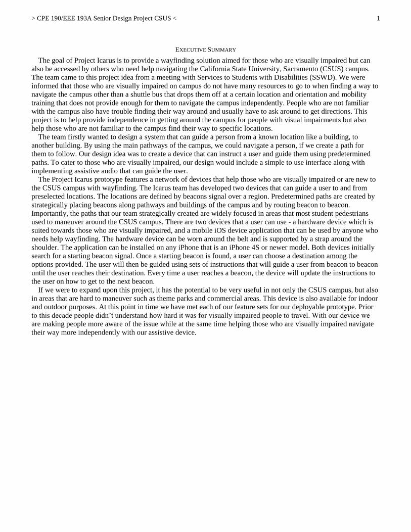
The goal of Project Icarus is to provide a wayfinding solution aimed for those who are visually impaired but can
also be accessed by others who need help navigating the California State University, Sacramento (CSUS) campus.
The team came to this project idea from a meeting with Services to Students with Disabilities (SSWD). We were
informed that those who are visually impaired on campus do not have many resources to go to when finding a way to
navigate the campus other than a shuttle bus that drops them off at a certain location and orientation and mobility
training that does not provide enough for them to navigate the campus independently. People who are not familiar
with the campus also have trouble finding their way around and usually have to ask around to get directions. This
project is to help provide independence in getting around the campus for people with visual impairments but also
help those who are not familiar to the campus find their way to specific locations. The team firstly wanted to design a system that can guide a person from a known location like a building, to
another building. By using the main pathways of the campus, we could navigate a person, if we create a path for
them to follow. Our design idea was to create a device that can instruct a user and guide them using predetermined
paths. To cater to those who are visually impaired, our design would include a simple to use interface along with
implementing assistive audio that can guide the user. The Project Icarus prototype features a network of devices that help those who are visually impaired or are new to
the CSUS campus with wayfinding. The Icarus team has developed two devices that can guide a user to and from
preselected locations. The locations are defined by beacons signal over a region. Predetermined paths are created by
strategically placing beacons along pathways and buildings of the campus and by routing beacon to beacon.
Importantly, the paths that our team strategically created are widely focused in areas that most student pedestrians
used to maneuver around the CSUS campus. There are two devices that a user can use - a hardware device which is
suited towards those who are visually impaired, and a mobile iOS device application that can be used by anyone who
needs help wayfinding. The hardware device can be worn around the belt and is supported by a strap around the
shoulder. The application can be installed on any iPhone that is an iPhone 4S or newer model. Both devices initially
search for a starting beacon signal. Once a starting beacon is found, a user can choose a destination among the
options provided. The user will then be guided using sets of instructions that will guide a user from beacon to beacon
until the user reaches their destination. Every time a user reaches a beacon, the device will update the instructions to
the user on how to get to the next beacon.
If we were to expand upon this project, it has the potential to be very useful in not only the CSUS campus, but also
in areas that are hard to maneuver such as theme parks and commercial areas. This device is also available for indoor
and outdoor purposes. At this point in time we have met each of our feature sets for our deployable prototype. Prior
to this decade people didn’t understand how hard it was for visually impaired people to travel. With our device we
are making people more aware of the issue while at the same time helping those who are visually impaired navigate
their way more independently with our assistive device.

> CPE 190/EEE 193A Senior Design Project CSUS <
2
CPE 190/EEE 193A Senior Design Project: Icarus End of Prototype Documentation
Anh Nguyen
ECS – Computer
Engineering
California State
University, Sacramento
Sacramento, United
States of America
Matthew Gorospe
ECS – Electrical and
Electronics Engineering
California State
University, Sacramento
Sacramento, United
States of America
Nolram Ansay
ECS – Computer
Engineering
California State
University, Sacramento
Sacramento, United
States of America
Rohit Pandit
ECS – Computer
Engineering
California State
University, Sacramento
Sacramento, United
States of America
Abstract— For our project, our societal problem is to create a series
of devices that will allow the assistance of visually impaired or incoming
students to traverse through the California State University, Sacramento
(CSUS) campus independently. The project’s objective is to guide the
user from a starting position to their destination using a set path while
utilizing iBeacon technology and network communication. With our
engineering skill sets, we plan to contribute into solving this societal
problem by utilizing electronic hardware and software technology. In
our design, we settled on a solution where we can accommodate both the
visually impaired and non-disabled students. In assisting the visually
impaired, we designed a portable device that has the ability to guide a
visually impaired user using a Raspberry Pi microcomputer. With its
ARM Cortex-A7 Quad Core processor, we are able to access the
Raspberry Pi’s high end features and enable it to accomplish the task of
guiding a user to their destination using Bluetooth Low Energy (BLE)
and preset paths. The path consists of Estimote beacons - which have
embedded iBeacon technology - that output BLE signals that can range
from 1.5 to 70 meters (m). Each beacon used is stored in a database that
contains all relevant information regarding the beacons. With the
information on the beacons, the portable device will have the ability to
create a path that leads from the user's starting position to their
destination while it outputs instructive audio to the user as they traverse
through the CSUS campus. In assisting the non-disabled students, we
decided to incorporate a mobile application that will cater to users who
have an iPhone device. Working with the Swift programming language,
we devised a user interface that performs the same functionalities as the
portable device with the exception that it is leaning more towards
students who are not familiar with the CSUS campus. At this stage of
the senior design project, we are at the phase where the product is ready
to be deployable. We achieved our objective for this project and were
successful at guiding a user from their starting position to their
destination on the CSUS campus. We wanted to promote awareness of
assistive technology and we believe that our project has succeeded in
achieving that awareness. We do not want to replace the existing tools
that are used today by disabled individuals; our goal is to contribute in
assisting people who lack support in the assistive technology area.
Overall, our project has met our expectations and is ready to provide the
needed support that the visually impaired are lacking.
Keywords—Apple, Blindness, Computer Engineering, Database,
Dijkstra’s Algorithm, Electrical and Electronics Engineering,
Estimote, iBeacon, IEEE Journal, Java, Market Review, Mobile
Application, Parse, Programming, Python, Raspberry Pi, Server,
Swift, Wayfinding.
I. INTRODUCTION
Wayfinding is a problem that every person faces in their life,
but is more challenging for those who are blind or visually
impaired. In a meeting with Melissa Repa, the Co-Director of
Services to Students with Disabilities (SSWD), it was revealed
to the Icarus team that there are not many resources available for
the visually impaired to help them navigate campus besides
some limited transportation services and orientation and
mobility training that does not fully prepare them. The goal of
Project Icarus is to provide a wayfinding solution aimed for
those who are visually impaired but can also be accessed by
others who need help navigating the CSUS campus. The Icarus
team designed a solution that allows a way for people to be
guided around campus by using easy to follow instructions that
will take users from building to building.
To do this, we design a hardware device, using a Raspberry Pi
2 Model B, to guide the user to their destination the CSUS
campus. The role of the hardware device is to guide the user,
using Bluetooth, to their destination by following a set path.
With the Raspberry Pi 2’s 900 megahertz (MHz) ARM Cortex
A7 Quad Core processor and 1 gigabyte (GB) RAM, we were
able to utilize its high end functionality to make wayfinding
possible. On top of the Raspberry Pi 2, we incorporated into the
design Bluetooth central role functionality that allows the
Raspberry Pi to be the recipient for signal receiving. The
hardware is utilizing Bluetooth 4.0 that operates under 2.4
gigahertz (GHz) frequency at an unlicensed industrial, scientific,
and medical (ISM) band. Essentially, the hardware is receiving
BLE signals that are being emitted from the beacons we are
utilizing. We are using Estimote beacons that contain iBeacon
technology invented by Apple which outputs BLE signals.
Contained in the BLE signals are identifier values - Universally
Unique Identifier (UUID), major, and minor values - that allow
the Raspberry Pi 2 the capability to differentiate beacons from
one another. With the identifier values that the hardware
receives from the beacons, they will be use to guide the user
from beacon to beacon until they reached their destination. The
way the hardware will be able to identify the beacon is by
accessing our third party backend database to retrieve
information on the beacons. We are using a database server,
Parse, which allows us to manage and modify data with its
unique features. Parse has effective tutorials and documentation

> CPE 190/EEE 193A Senior Design Project CSUS <
3
that can make developing a database easier for those with no
experience in database management.
Essentially, we also have a mobile application that performs
the same functionality similar to the hardware device, but the
solution leans towards students with no familiarity of the CSUS
campus. We developed an iOS application that will only work
on iPhone devices that have Bluetooth capabilities, which is the
4S model and above, and Operating System (OS) that operates
at version 8.0 and above. To develop this application, we are
using an object oriented programming language, Swift, to
program the logic that will operate with the database and
Estimote beacons. Since Apple developed iBeacon technology,
iOS has access to application program interfaces (APIs) that
allow easier access to programmable libraries for iBeacon
technology. Parse also has tutorial that allow easy setup for an
iOS mobile application, making developing the application
easier for programmers.
Throughout our senior design process, we wanted to make
sure that our product meets our expectations and operates the
way it should. During the process, we needed to understand our
problem at a technical level and how we should devise a
solution while using engineering. Once we developed a strategy
to solve our societal problem, our team diligently started to
apply our engineering concepts to design our project. This
involved developing a design idea, feature set, work breakdown
structure, risk assessment, device test plan, and other concepts.
The process was a definite struggle, but a worthwhile one. There
were many things that we wanted to consider for our project, but
the implementation of the system to the whole campus was not
feasible due to the budget of the team and available time for the
project. The prototype was still able to demonstrate the design
idea and also meet the feature set that the team devised. Testing
revealed that response time of the device to the beacon signals
can take time and may need further research to get more
accurate beacon regions. Further implementation of this system
to the campus may need a way to maintain beacons manage
system failures. This project promotes and gives awareness for
the need of assistive technology and displays the power of new
technology which can be used to provide accessibility and
convenience for those with disabilities.
II. SOCIETAL PROBLEM
Project Icarus is primarily focusing on assisting students with
visual impairment. Based on what our team knows, statistically
there is a sizable amount of people who have a certain disability.
According to the California State University (CSU) official
website [1], CSUS enrolled about 30,000 students during the Fall
semester in 2014. Within the 30,000 students, about 600 of the
students have a disability. Overall, only 25 students have visual
impairment. Even though the number seems insignificant, 25
students who are visually impaired is a very impacting value. With
the tools that are available to the visually impaired, it is still
difficult for the person to perform daily tasks without the help of
others. According to Melissa Repa, the Co-Director of SSWD,
CSUS has the highest number of disabled students in the CSU
system, which includes visually impaired people. Knowing that
CSUS enrolls many disabled students, this brought great concern
that worried us. One of the problems that many students are having
difficulties with is traversing the CSUS campus. With roughly over
30,000 students that are enrolled, students with disabilities have
greater difficulty navigating through the campus. Usually, when
the visually impaired students are given a tour, they are usually
given one tour of the campus. In a way, we believe that it would be
very difficult for the student to get a visual of the campus without
some form of tool or method to help them remember the campus
layout. Our project can provide assistance to the visually impaired
and offer another assistive tool for them to use.
A. Blindness and its Effects
1) Definition of Blindness
Blindness has a very broad definition. Strictly speaking,
blindness is defined as the state of being totally sightless in both
eyes [2]. Blindness is usually a term that leans toward visual
impairment or low vision, which means that even with eyeglasses,
contact lenses, or surgery, a person still, does not have the ability
to see well. Around the world, between 300 million to 400 million
are visually impaired from various causes [2]. From the 300
million to 400 million people, 50 million people are completely
blind, meaning they cannot see light in both eyes. Lastly, 80% of
blindness occurs in people 50 years or older. According to the International Classification of Diseases, there
are four levels of visual functions [3]:
1) normal vision 2) moderate visual impairment 3) severe visual impairment 4) Blindness
When grouping moderate visual impairment, it is then consider
low vision. Low vision taken together with blindness
represents all visual impairment [3].
> CPE 190/EEE 193A Senior Design Project CSUS <
4
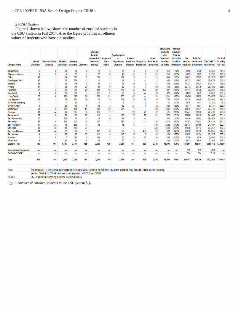
2) CSU System
Figure 1 shown below, shows the number of enrolled students in
the CSU system in Fall 2014. Also the figure provides enrollment
values of students who have a disability.
Fig. 1. Number of enrolled students in the CSU system [1].

> CPE 190/EEE 193A Senior Design Project CSUS <
5
As it has already been stated, there were 29,349 students that
enrolled for the Fall 2014 semester. Out of the 29,349 students,
679 students have a certain disability. Finally, only 25 students
from the 679 students were visually limited or impaired. As we
were told by SSWD, CSUS has enrolled roughly over 30,000
students in the 2015-2016 academic year. With the large increase
of student enrollment at CSUS, there is a slight chance that a
handful of the students that enrolled in that academic year will
have a disability and it can be a visual disability. Seeing that CSUS
has a large amount of disabled students in the CSU system, this is
impacting to the college campus itself because CSUS only has
much to offer in terms of assistive tools to the students with
disabilities. Without these assistive tools, this hinders and limits
the student’s college experience.
3) Available Technology
During the preliminary stages of our team’s designing stage, we
had to make observations of the available technology. Two items
that showed up on most of the assistive sources that we looked into
were braille printers and GPS systems [4].
Individuals that have severe loss of sight rely on hearing and
feeling as a way of understanding their surroundings. The braille
printer allows for a convenient method of producing readable text
for the visually impaired. Unfortunately, this product has a high
cost. The braille printer shown in Figure 2 shows a high end braille
printer with a cost as high as forty five hundred dollars. Other popular components are systems that utilize Global
Positioning System (GPS), which essentially relay regional
information to the user, notifying them of their general location.
However, GPS is very inaccurate for short distances, and can cause
harm to the visually impaired. For instance, a GPS routing system
can tell a visually impaired person that there is a road 10 feet (ft)
away when in actuality the road is only 5 ft. As far as available technology, one of the common tools that
visually impaired individuals utilize is the walking cane. The cane
allows the person to feel the ground in their frontal area as they
walk.
There's a diverse amount of resources available for visually
impaired individuals ranging from certain programs or even
software. There are various softwares that are capable of
interpreting symbols. Many places have utilized this type of
software to allow text to speech. Colleges generally have
departments that are in charge of ensuring that students with
disabilities such as visual impairment are accommodated properly.
B. Understanding our Societal Problem
Over the course of the design project, our team was able to
broaden our understanding of the societal issue to which our design
pertains to. At this point of our project, we now have a better
perception of the societal problem and how to accomplish the
engineering solution to the problem. The solution that our team has
designed, so far, is not a perfect solution to the societal problem,
but it is another alternative for the visually impaired person to
assist themselves and abolish their dependency on other people.
There were steps taken to arrive where our team is currently and
this directed us into understanding exactly how the problem affects
visually impaired people and how we plan to assist them.
1) Existing Solutions
As we were designing our project, we researched several
existing solutions that are available to aid a visually impaired
person. With these existing solutions, this helped us understand the
experiences of a visually impaired person and how our team can
design a solution that can accommodate their needs. Looking into
current works that are in progress we hope to broaden our insight
to the problem that we are addressing.
a) RFID Tags
The European Union’s Institute for the Protection and Security
of the Citizen (IPSC) in Ispra, Italy designed a solution where they,
“embedded 1260 RFID transponders into the sidewalks of Laveno
Mombello, in the north of Italy, and linked them together in a
network called SESAMONET” [6]. They are utilizing radio-
frequency identification (RFID) tags [6], which are used wirelessly
with electromagnetic fields that transfer data on attached objects.
In their solution, the user will have an antenna that will activate
the RFID chip as the user passes over it, relaying its unique tag
number to a smartphone. The phone will contain a database of
navigational information that will map the tag numbers location.
With that, the user will receive specific information about the
position and surroundings through a Bluetooth headset.
b) Wayfindr
Wayfindr is another solution to assist visually impaired people
to travel independently. They used “off the shelf” products that
utilize BLE signals. They used Estimote beacons that uses iBeacon
technology that transmit BLE signals [8].
Fig. 3. Top of the line braille printer [4].
Fig. 2. White cane [5].

> CPE 190/EEE 193A Senior Design Project CSUS <
6
Placing the beacons in a predetermined path, the visually impaired
person is able to help navigate themselves to these beacons,
eventually leading to their destination.
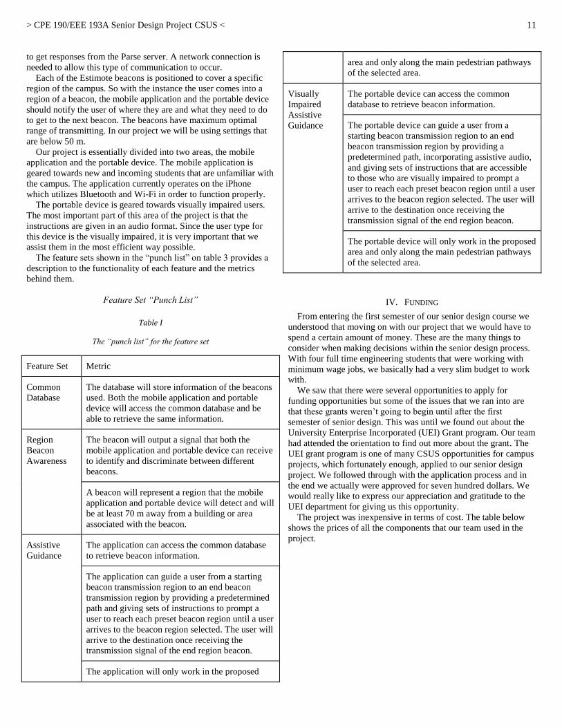
c) Our Approach to the Design
As we approached our design, our team needed a clearer idea of
how a visually impaired person operates when they are alone. In
our research, we found that people have performed numerous tests
to understand how a visually impaired person operates under
certain conditions. Figure 4 shows the participants who were
involved in the experiment and describes the tools they were using,
the city they are in, and what caused their condition. The goal of
this test is to understand the experience that the visually impaired
person has to endure as they act independently. The experiment
also analyzed several navigation strategies that a visually impaired
person uses as they face unexpected obstacles. When reading this
document, we realized that the visually impaired person needs to
have some form of visual representation or picture of the area that
they are traveling. In our design idea, we believe that we need to
be able to give a good understanding of the CSUS campus layout.
Once the person has the understanding of the layout, the visually
impaired person can navigate themselves without assistance. This
involves us searching for paths that may cause problems for the
person when they travel alone through the campus. This will be an
effective way to assist the person because we will be dictating to
them obstacles that may hinder their navigation to their destination.
This way, they can feel at ease when they traverse the campus
knowing that they have something guiding them along the way. A
similar implementation, we want to incorporate that was utilized in
Wayfindr is to have predetermined spots that the user can go to
using “signals” as their guide to navigate the campus. This will, in
turn, reduce the chances of getting lost, knowing that the way
points will guide them to the correct location.
Fig. 4. RFID [7].
Fig. 5. Estimote beacons [8].
> CPE 190/EEE 193A Senior Design Project CSUS <
7
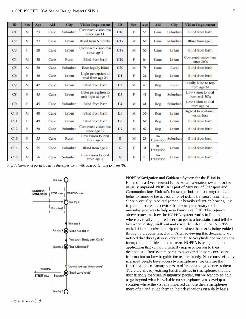
NOPPA:Navigation and Guidance System for the Blind in
Finland is a 3 year project for personal navigation system for the
visually impaired. NOPPA is part of Ministry of Transport and
Communications Finland’s Passenger information program that
helps to improve the accessibility of public transport information.
Since a visually impaired person is heavily reliant on hearing, it is
important to create a device that is complementary to their
everyday practices to help ease their travel [10]. The Figure 7
above represents how the NOPPA system works in Finland to
where a visually impaired user can get to a bus station and tell the
bus when to stop, walk out and reach their destination. NOPPA
called this the “unbroken trip chain” since the user is being guided
through a predetermined path. After reviewing this document, we
noticed that this system is very similar to Wayfindr and we want to
incorporate their idea into our own. NOPPA is using a mobile
application that can aid a visually impaired person to their
destination. Their system contains a server that stores necessary
information on how to guide the user correctly. Since most visually
impaired people have access to smartphones, we can use the
functionalities of smartphones to offer assistive guidance to them.
There are already existing functionalities in smartphones that are
user friendly for visually impaired people, but we want to be able
to go beyond what is available on smartphones and develop a
solution where the visually impaired can use their smartphones
more often and guide them to their destinations on a daily basis.
Fig. 7. Number of participants in the experiment with data pertaining to them [9].
Fig. 6. NOPPA [10].

> CPE 190/EEE 193A Senior Design Project CSUS <
8
III. DESIGN IDEA AND THE FEATURE SET
A. Design Idea
In our research, there were existing products that help guide
visually impaired people to their destinations. But, the one that
captured our attention was the Wayfindr [11], a beacon device
created by engineers in London, who are involved with the Royal
London Society for Blind (RLSB) that guides people accurately to
their destinations by speaking to the user.
How the Wayfindr works is that it has several beacons placed in
certain locations, which in their case is the London subway station
in Figure 8. Each beacon is different than the other when it comes
to giving directions. Meaning, each beacon will have a certain way
of reaching that beacon.
For example, taking the stairs or walking a few feet to the next
beacon. The beacons are used to tell the user that they have
reached the designated beacon and are getting closer to the
destination. Wayfindr uses a mobile application that guides the
user through the beacons. The user will have an audio device
connected to the mobile application so that they can hear their
current location and direct themselves to the next location. The
mobile application will then tell the user through the audio device
which beacon to go to. Once the user reaches their pinpointed
beacon, the beacon will then sound off, notifying the user that
he/she reached their first destination. The user will continue to
navigate through a series of beacons until the user reaches their
final destination.
By observing this knowledgeable approach, we want to design a
solution that is very similar to this. We want to use numerous
beacons that will guide the students on campus to his/her chosen
location. Like Wayfindr, each beacon will have a specified way to
getting to the beacon depending where the beacons are placed. To
figure out where to place the beacons, we would need to survey the
CSUS campus to find possible locations to place our beacons. In
our design, the iBeacon will communicate with both the mobile
application and hardware device, which will direct the user to the
beacons and lead the user to his/her destination. The devices will
continue to direct the user to each beacon until the user reaches
their destination. Additionally to our project, we want to be able to
find the shortest path possible to the chosen destination by the user.
One way to approach this problem is to measure the distances to
every possible location on campus. Once we figure out the
distances in each location, we will implement a computer
programming algorithm that will calculate the shortest and fastest
distance to each destination. This is efficient to our design because
there are dozens of possible routes that a disabled or non-disabled
student can take to get to their destination. This routing algorithm
primarily focuses on finding the fastest and shortest path, which is
perfect for what we want to implement in our design. This will
save time for the person that is navigating through unfamiliar
territory. Just like Wayfindr, we will use an audio device or output
to speak to the user. We will incorporate sounds that will alert the
user that he/she is either getting closer to the pinpointed beacon or
has reached the beacon. The sounds from the audio device will
help the disabled student know that he/she reached their chosen
destination.
In large, the approached idea is well-organized and effective.
The ideas that have been brought to mind are very efficient and
easy for students to travel around campus. The solution we thought
of fit our qualifications and these ideas apply to our design. There
are other possible designs, but we will implement what we have
and if possible, add the other solutions we have discovered that
may help with our design.
1) Mobile Application
In this design, we want to implement a mobile application that
will allow the user to communicate with the beacons. There were
many solutions that can be implemented into our application, but
our main focus is to keep it simple enough where the person can
use it without complications. The application will be programmed
in the iOS platform for users who have an iPhone mobile device.
The application will be programmed in an iOS programming
language familiar to our group, which is Swift. Another iOS
programming language, Objective-C, can be implemented in our
design as well if the situation arises. Mainly, our application will
be using the Swift programming language because of its simplicity
and familiarity. Overall, the application can be used by either
disabled or non-disabled students.
The way the mobile application will work is that it will ask or
prompt the user for a location to go to. The user will have a list of
locations where the user can choose from. Once the user has
chosen their destination, the application will analyze and choose a
path that will be the fastest and shortest route to the user’s desired
location using a routing algorithm. The routing algorithm data will
be stored in a server where the mobile application will have access
to and be able to manipulate the data. With the routing algorithm,
the application will get the routing data and navigate through the
necessary beacons that the algorithm calculated. Once the user
starts making his/her way to the destination, the mobile application
will notify the user if he/she reached the pinpointed beacon that
leads to the chosen location. The way that the user will know if
he/she reached a beacon is through an alert sound or some sort of
audio output. When the user finally reaches the beacon, an audio
output will notify the user of its current location. The mobile
application will continue to guide the user through each pinpointed
beacon until the user reaches the desired location.
In our application, we are integrating many possible features that
will mainly tailor to non-disabled students. In the application,
Fig. 8. Map of the London subway station with beacon locations [11].

> CPE 190/EEE 193A Senior Design Project CSUS <
9
instead of having a map of the CSUS campus, it will have a list of
all the buildings on campus for the user to choose from. This will
make it easier for a visually impaired student to use because they
have no knowledge of the map, making it difficult for the blind
student to use the application. By making it a list than a map, the
user can pick from the list of buildings on campus and the
application will find the quickest route to the chosen location. But,
the most crucial part of the mobile application is the routing
algorithm. This is how the user will actually get the routing
information to the location. The routing algorithm will have to
calculate the shortest and fastest path out of all the possible paths
that can be made to get to the chosen location. The efficient aspect
of the routing algorithm is that there are many short and fast paths
that can lead the user to his/her chosen location, but essentially it
will pick the best one. However, there are certain constraints that
make implementing the algorithm very difficult. One of the
challenging aspects of the routing algorithm is actually
programming the algorithm. There are many possible locations to
consider when programming the algorithm. So, there is a large
room for error and it can make programming the application very
difficult to do. Another problem that can arise in the application is
if the data is not received correctly from the database. Even with
careful testing, something can still go wrong when it is actually
implemented. If it obtains incorrect information from the server,
the user will get incorrect directions to the beacons and the user
will not get to the destination accurately and it would waste time,
which defeats the purpose of the application. The least probable
cause would be if the application crashed. If the application were
to crash for any reason, we would have to find the malfunction in
the program and figure out a solution.
There are many other solutions and ideas that can be applied to
the mobile application, but the ideas mentioned are what will
constitute the design of the application. The ideas targeted the
main points of what our application should be doing for the user.
Throughout the programming process, there will be a possibility
that other ideas will be employed into our design, but again, our
application will be as simple as possible for the user to use. The
goal for the application, overall, should be able to direct the user to
the beacons and destination in a fast and safe manner.
2) Dijkstra’s Algorithm
Created by Edgar W. Dijkstra, Dijkstra Algorithm is a routing
algorithm that calculates and formulates the shortest path from one
position to all possible positions [12]. There are many routing
algorithms that can be used in our design, but Dijkstra’s Algorithm
is simple and easy to implement because the concept is familiar in
our group and we understand how to apply it. It is one of the most
popular algorithms that are used today as a basis of learning and
implementation. And as a short routing algorithm, this will
calculate the shortest route possible out of all the possible routes
that are available on the CSUS campus, which is one of the goals
that our design should achieve. So, we will use this particular
algorithm for this mobile application because it is guaranteed a
shorter and faster path.
As it is already mentioned, the algorithm will generate a short
path to a destination of any choosing. Wherever the user’s starting
and end point is, the algorithm will create a path in a short and
timely manner. In Figure 9, it demonstrates the implementation of
Dijkstra’s Algorithm and possible routes.
How the algorithm works is it develops the shortest path by
generating the shortest path tree (SPT). The SPT will contain two
sets, one set that contains vertices in the SPT and the other set will
have vertices not in the SPT. In every step of the algorithm, it will
find a vertex in the set with no vertices and has the minimum
distance from the starting point, which is referred to as the source.
In detail [12], this is how the algorithm is actually performed:
1) Creates a set that keeps track of the vertices in SPT, whose
minimum distance from the source is calculated and
finalized. From the initial start, the set is empty.
2) Assigns a distance value to all vertices in the input graph.
Initialize all distance values to infinity. The reason the value
is initialized to infinity is because it is easy to cope in
situations where the problem is not feasible [13]. Meaning,
there is no path from one spot to another. So, if there is no
direct link from one spot to another, then it is equal to
infinity. Then we assign a value 0 to the source so that it
signifies the starting point.
3) While the set does not include all vertices
A) Pick a vertex which is not in the set that has the minimum
distance value.
B) Include the vertex in the set
C) Update the distance value of all adjacent vertices. To
update the distance values, the algorithm would iterate
through all the adjacent vertices. For every adjacent
vertex, it would have to do a mathematical calculation to
find the value with the least distance from the source and
update the set.
Generally, this is the most crucial and important part of our
design. The goal, again, is to find the shortest and fastest path to
the user’s destination without the user having to think of a possible
route. This algorithm should handle majority of the work and
hopefully direct the user to the destination correctly. Since our
group is dealing with possible routes on the CSUS campus, it will
be a challenge to program this algorithm. But, this algorithm, by
far, is the most efficient way of finding a path without difficulty.
3) Surveying and expedition of the CSUS Campus
Our project will require a survey of the campus of where we can
place our beacons and what areas we want to landmark for those
using our device. This will essentially determine the paths for the
visually impaired person. We need to find paths that are possible
for the visually impaired person to navigate through. As we survey
for possible spots on the CSUS campus, we want to make sure that
the path is manageable by the visually impaired person and he/she
will be able to follow the path. We are not going to choose paths
Fig. 9. Implementation of Dijstra's Algorithm [12].

> CPE 190/EEE 193A Senior Design Project CSUS <
10
that will lead them unnecessary territory like grass or rock filled
grounds. It will mainly be clear paths that will lead to their
destination as simple as possible.
4) Software and Computer Programming
a) Xcode
Xcode will be the primary software compiler for creating the
mobile application for our device [14]. This application will
contain a list of the campus buildings for those who want to use the
device for help in navigating the campus. The application’s main
purpose will be to aid the non-visually impaired and will feature
audio output that will play when passing a beacon. Xcode is an
Integrated Development Environment (IDE) made by Apple and is
used to create applications for Apple products using iOS or OS X
such as the iTouch, iPhone, Macbook, or iPad. This program also
features a suite of software development tools that can be used in
the application [15]. One of the tools included is the interface
builder, which allows the user to map out the application being
made. This feature allows the user to keep track of what the
application interface will look like if a person downloads the
application and uses it. Xcode is currently on version 7.0 and
supports many different programming languages such as C, C++,
Java, Objective-C, and Swift.
b) Swift iOS Programming Language
Swift is an object-oriented programming language created by
Apple and is used for platforms such as iOS, OS X, and watchOS
[15]. Swift will be primarily used in our project to create an
application to be used on the iPhone device. If there is a need, we
can also incorporate Objective-C iOS programming language into
our application. Both languages can be used in coherence with
each other even though they have different syntaxes. The
programming language syntax and style has influences from C and
Objective-C. Swift also has a new iteration called Swift 2.0, which
further improves the Swift programming language [15]. Again,
Swift is going to be the main programming language we use when
utilizing Xcode because of its simplicity for beginner
programmers.
5) Electronic Hardware
a) Python Programming Language
Python is an interpreted, object-oriented, high-level programming
language with dynamic syntaxes. With its high-level implementation and
dynamic syntaxes, it makes it powerful for Rapid Application
Development, as well as for use as a scripting language to connect existing
components together [16]. Python is a programming language that is easy
to learn and understand and it will be our primary tool in programming the
logic in our hardware because we utilize extra hardware in our design that
needs a script for it to make it functional. This is something our team
learned as we design our project, but Python is an effective and
powerful programming language to use in our project.
b) Bluetooth
Bluetooth is a way for devices to communicate wirelessly. It
operates at the range of 2.4 to 2.485 gigahertz (GHz) in the
industrial, scientific, and medical (ISM) band and used to
exchange data over short distances. Bluetooth was invented in
1994 by Ericsson. This technology runs on low power and is very
secure. Devices with Bluetooth functionality can connect to each other
by "pairing” as long as the devices are in proximity. The devices
create an ad hoc network, which users can enter and leave. Each
device can also connect to seven other devices in the network and
connect to several networks at one time. [17] Bluetooth has
adaptive frequency hopping capability that reduces interference
with other devices using the same spectrum by adjusting the
frequency of the signal in the range of the band at 1 MHz intervals.
The operational range of Bluetooth depends on the class of the
radio used on the device. The most common class is Class 2 that
has a range of 10 m and use about 2.5 milliwatt (mW). This shows
the low power consumption of Bluetooth technology.
c) Hardware
We have several choices for what we want to use as part of our
hardware section. We will primarily be working with the
Raspberry Pi 2 Model B, which has 1 GB of RAM and an ARM
Cortex A7 900 MHz CPU. How we will be implementing is by
using multiple adapters to actually enable Bluetooth scanning and
an internet connection to the database server. We will then need to
figure out a program to run through the Raspberry Pi to make this
all mesh together. That means we will need to find specific
libraries that actually enable Bluetooth scanning on the Raspberry
Pi such as "PyblueZ." We will also need to configure the
Raspberry pi to actually connect to the network, since our project
requires that the device be connected to the internet in order to
access data from the server. We will be utilizing the ASUS
Bluetooth adapter and the Edimax Wi-Fi adapter. There are
multiple programming languages that we could implement into the
hardware, but we will most likely be choosing Python since it will
be much easier to integrate than using C language. One of the unique aspects of our project is that we will have
digital landmarks. By using iBeacon technology, we will have the
Raspberry Pi recognize the signal and be able to differentiate
between regions of the campus and also be able to assist anyone
who is trying to navigate the campus. We will be using Estimote
beacons that utilize iBeacon technology for the Raspberry Pi to
recognize. The iBeacons that we have seen on the market have a
range of 40 to 70 m approximately [18]. With that constraint we
now have an idea of how many we might need when we survey the
campus. All the beacons will act as a network that will give the
Raspberry Pi an idea of which region they are in [19].
B. Feature Set
Obviously, the project’s goal is to guide a visually impaired or
non-disabled student to their destination without any form of
assistance. In our feature set, it includes aspects that will help
design our project:
1) Common Database
2) Region Beacon Awareness
3) Assistive Guidance
4) Visually Impaired Assistive Guidance
Each feature has a specific concentration that will play a part in
solving our societal problem. At the same time, they are broken
down to further levels to explore their functionality and
responsibilities that will be involved in designing each level.
The common data base is a very important section of our
project. We are using a third party backend, Parse, which provides
free data storage and management services. We will be storing
important beacon data within the server. The portable device
utilizes REST API which is a programming protocol that allows us
> CPE 190/EEE 193A Senior Design Project CSUS <
11
to get responses from the Parse server. A network connection is
needed to allow this type of communication to occur.
Each of the Estimote beacons is positioned to cover a specific
region of the campus. So with the instance the user comes into a
region of a beacon, the mobile application and the portable device
should notify the user of where they are and what they need to do
to get to the next beacon. The beacons have maximum optimal
range of transmitting. In our project we will be using settings that
are below 50 m.
Our project is essentially divided into two areas, the mobile
application and the portable device. The mobile application is
geared towards new and incoming students that are unfamiliar with
the campus. The application currently operates on the iPhone
which utilizes Bluetooth and Wi-Fi in order to function properly.
The portable device is geared towards visually impaired users.
The most important part of this area of the project is that the
instructions are given in an audio format. Since the user type for
this device is the visually impaired, it is very important that we
assist them in the most efficient way possible.
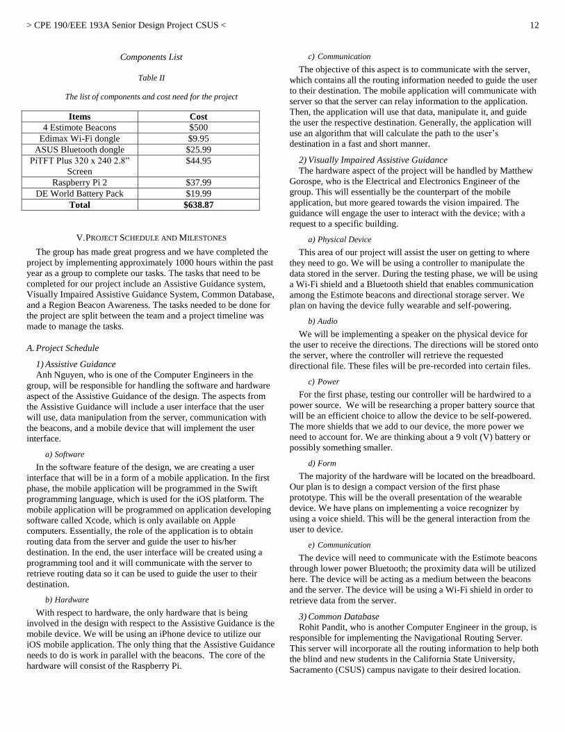
The feature sets shown in the “punch list” on table 3 provides a
description to the functionality of each feature and the metrics
behind them.
Feature Set “Punch List”
Table I
The “punch list” for the feature set
Feature Set Metric
Common
Database
The database will store information of the beacons
used. Both the mobile application and portable
device will access the common database and be
able to retrieve the same information.
Region
Beacon
Awareness
The beacon will output a signal that both the
mobile application and portable device can receive
to identify and discriminate between different
beacons.
A beacon will represent a region that the mobile
application and portable device will detect and will
be at least 70 m away from a building or area
associated with the beacon.
Assistive
Guidance
The application can access the common database
to retrieve beacon information.
The application can guide a user from a starting
beacon transmission region to an end beacon
transmission region by providing a predetermined
path and giving sets of instructions to prompt a
user to reach each preset beacon region until a user
arrives to the beacon region selected. The user will
arrive to the destination once receiving the
transmission signal of the end region beacon.
The application will only work in the proposed
area and only along the main pedestrian pathways
of the selected area.
Visually
Impaired
Assistive
Guidance
The portable device can access the common
database to retrieve beacon information.
The portable device can guide a user from a
starting beacon transmission region to an end
beacon transmission region by providing a
predetermined path, incorporating assistive audio,
and giving sets of instructions that are accessible
to those who are visually impaired to prompt a
user to reach each preset beacon region until a user
arrives to the beacon region selected. The user will
arrive to the destination once receiving the
transmission signal of the end region beacon.
The portable device will only work in the proposed
area and only along the main pedestrian pathways
of the selected area.
IV. FUNDING
From entering the first semester of our senior design course we
understood that moving on with our project that we would have to
spend a certain amount of money. These are the many things to
consider when making decisions within the senior design process.
With four full time engineering students that were working with
minimum wage jobs, we basically had a very slim budget to work
with.
We saw that there were several opportunities to apply for
funding opportunities but some of the issues that we ran into are
that these grants weren’t going to begin until after the first
semester of senior design. This was until we found out about the
University Enterprise Incorporated (UEI) Grant program. Our team
had attended the orientation to find out more about the grant. The
UEI grant program is one of many CSUS opportunities for campus
projects, which fortunately enough, applied to our senior design
project. We followed through with the application process and in
the end we actually were approved for seven hundred dollars. We
would really like to express our appreciation and gratitude to the
UEI department for giving us this opportunity.
The project was inexpensive in terms of cost. The table below
shows the prices of all the components that our team used in the
project.
> CPE 190/EEE 193A Senior Design Project CSUS <
12
Components List
Table II
The list of components and cost need for the project
Items Cost
4 Estimote Beacons $500
Edimax Wi-Fi dongle $9.95
ASUS Bluetooth dongle $25.99
PiTFT Plus 320 x 240 2.8”
Screen
$44.95
Raspberry Pi 2 $37.99
DE World Battery Pack $19.99
Total $638.87
V. PROJECT SCHEDULE AND MILESTONES
The group has made great progress and we have completed the
project by implementing approximately 1000 hours within the past
year as a group to complete our tasks. The tasks that need to be
completed for our project include an Assistive Guidance system,
Visually Impaired Assistive Guidance System, Common Database,
and a Region Beacon Awareness. The tasks needed to be done for
the project are split between the team and a project timeline was
made to manage the tasks.
A. Project Schedule
1) Assistive Guidance
Anh Nguyen, who is one of the Computer Engineers in the
group, will be responsible for handling the software and hardware
aspect of the Assistive Guidance of the design. The aspects from
the Assistive Guidance will include a user interface that the user
will use, data manipulation from the server, communication with
the beacons, and a mobile device that will implement the user
interface.
a) Software
In the software feature of the design, we are creating a user
interface that will be in a form of a mobile application. In the first
phase, the mobile application will be programmed in the Swift
programming language, which is used for the iOS platform. The
mobile application will be programmed on application developing
software called Xcode, which is only available on Apple
computers. Essentially, the role of the application is to obtain
routing data from the server and guide the user to his/her
destination. In the end, the user interface will be created using a
programming tool and it will communicate with the server to
retrieve routing data so it can be used to guide the user to their
destination.
b) Hardware
With respect to hardware, the only hardware that is being
involved in the design with respect to the Assistive Guidance is the
mobile device. We will be using an iPhone device to utilize our
iOS mobile application. The only thing that the Assistive Guidance
needs to do is work in parallel with the beacons. The core of the
hardware will consist of the Raspberry Pi.
c) Communication
The objective of this aspect is to communicate with the server,
which contains all the routing information needed to guide the user
to their destination. The mobile application will communicate with
server so that the server can relay information to the application.
Then, the application will use that data, manipulate it, and guide
the user the respective destination. Generally, the application will
use an algorithm that will calculate the path to the user’s
destination in a fast and short manner.
2) Visually Impaired Assistive Guidance
The hardware aspect of the project will be handled by Matthew
Gorospe, who is the Electrical and Electronics Engineer of the
group. This will essentially be the counterpart of the mobile
application, but more geared towards the vision impaired. The
guidance will engage the user to interact with the device; with a
request to a specific building.
a) Physical Device
This area of our project will assist the user on getting to where
they need to go. We will be using a controller to manipulate the
data stored in the server. During the testing phase, we will be using
a Wi-Fi shield and a Bluetooth shield that enables communication
among the Estimote beacons and directional storage server. We
plan on having the device fully wearable and self-powering.
b) Audio
We will be implementing a speaker on the physical device for
the user to receive the directions. The directions will be stored onto
the server, where the controller will retrieve the requested
directional file. These files will be pre-recorded into certain files.
c) Power
For the first phase, testing our controller will be hardwired to a
power source. We will be researching a proper battery source that
will be an efficient choice to allow the device to be self-powered.
The more shields that we add to our device, the more power we
need to account for. We are thinking about a 9 volt (V) battery or
possibly something smaller.
d) Form
The majority of the hardware will be located on the breadboard.
Our plan is to design a compact version of the first phase
prototype. This will be the overall presentation of the wearable
device. We have plans on implementing a voice recognizer by
using a voice shield. This will be the general interaction from the
user to device.
e) Communication
The device will need to communicate with the Estimote beacons
through lower power Bluetooth; the proximity data will be utilized
here. The device will be acting as a medium between the beacons
and the server. The device will be using a Wi-Fi shield in order to
retrieve data from the server.
3) Common Database
Rohit Pandit, who is another Computer Engineer in the group, is
responsible for implementing the Navigational Routing Server.
This server will incorporate all the routing information to help both
the blind and new students in the California State University,
Sacramento (CSUS) campus navigate to their desired location.
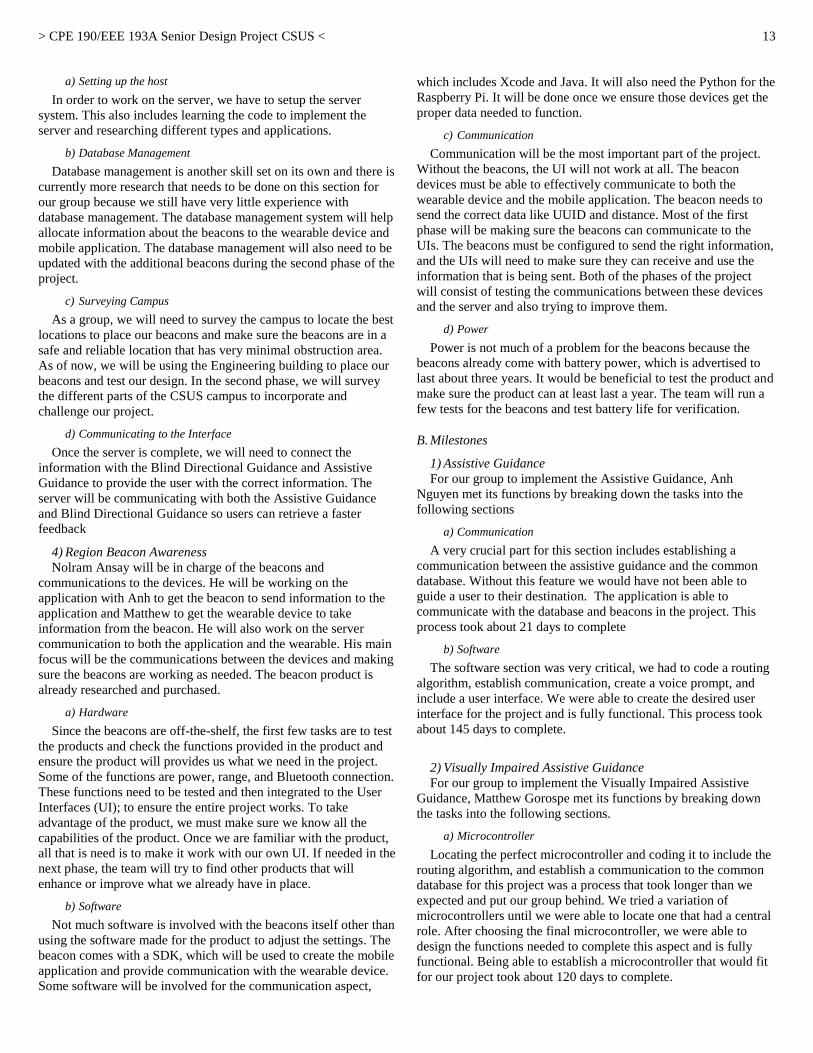
> CPE 190/EEE 193A Senior Design Project CSUS <
13
a) Setting up the host
In order to work on the server, we have to setup the server
system. This also includes learning the code to implement the
server and researching different types and applications.
b) Database Management
Database management is another skill set on its own and there is
currently more research that needs to be done on this section for
our group because we still have very little experience with
database management. The database management system will help
allocate information about the beacons to the wearable device and
mobile application. The database management will also need to be
updated with the additional beacons during the second phase of the
project.
c) Surveying Campus
As a group, we will need to survey the campus to locate the best
locations to place our beacons and make sure the beacons are in a
safe and reliable location that has very minimal obstruction area.
As of now, we will be using the Engineering building to place our
beacons and test our design. In the second phase, we will survey
the different parts of the CSUS campus to incorporate and
challenge our project.
d) Communicating to the Interface
Once the server is complete, we will need to connect the
information with the Blind Directional Guidance and Assistive
Guidance to provide the user with the correct information. The
server will be communicating with both the Assistive Guidance
and Blind Directional Guidance so users can retrieve a faster
feedback
4) Region Beacon Awareness
Nolram Ansay will be in charge of the beacons and
communications to the devices. He will be working on the
application with Anh to get the beacon to send information to the
application and Matthew to get the wearable device to take
information from the beacon. He will also work on the server
communication to both the application and the wearable. His main
focus will be the communications between the devices and making
sure the beacons are working as needed. The beacon product is
already researched and purchased.
a) Hardware
Since the beacons are off-the-shelf, the first few tasks are to test
the products and check the functions provided in the product and
ensure the product will provides us what we need in the project.
Some of the functions are power, range, and Bluetooth connection.
These functions need to be tested and then integrated to the User
Interfaces (UI); to ensure the entire project works. To take
advantage of the product, we must make sure we know all the
capabilities of the product. Once we are familiar with the product,
all that is need is to make it work with our own UI. If needed in the
next phase, the team will try to find other products that will
enhance or improve what we already have in place.
b) Software
Not much software is involved with the beacons itself other than
using the software made for the product to adjust the settings. The
beacon comes with a SDK, which will be used to create the mobile
application and provide communication with the wearable device.
Some software will be involved for the communication aspect,
which includes Xcode and Java. It will also need the Python for the
Raspberry Pi. It will be done once we ensure those devices get the
proper data needed to function.
c) Communication
Communication will be the most important part of the project.
Without the beacons, the UI will not work at all. The beacon
devices must be able to effectively communicate to both the
wearable device and the mobile application. The beacon needs to
send the correct data like UUID and distance. Most of the first
phase will be making sure the beacons can communicate to the
UIs. The beacons must be configured to send the right information,
and the UIs will need to make sure they can receive and use the
information that is being sent. Both of the phases of the project
will consist of testing the communications between these devices
and the server and also trying to improve them.
d) Power
Power is not much of a problem for the beacons because the
beacons already come with battery power, which is advertised to
last about three years. It would be beneficial to test the product and
make sure the product can at least last a year. The team will run a
few tests for the beacons and test battery life for verification.
B. Milestones
1) Assistive Guidance
For our group to implement the Assistive Guidance, Anh
Nguyen met its functions by breaking down the tasks into the
following sections
a) Communication
A very crucial part for this section includes establishing a
communication between the assistive guidance and the common
database. Without this feature we would have not been able to
guide a user to their destination. The application is able to
communicate with the database and beacons in the project. This
process took about 21 days to complete
b) Software
The software section was very critical, we had to code a routing
algorithm, establish communication, create a voice prompt, and
include a user interface. We were able to create the desired user
interface for the project and is fully functional. This process took
about 145 days to complete.
2) Visually Impaired Assistive Guidance
For our group to implement the Visually Impaired Assistive
Guidance, Matthew Gorospe met its functions by breaking down
the tasks into the following sections.
a) Microcontroller
Locating the perfect microcontroller and coding it to include the
routing algorithm, and establish a communication to the common
database for this project was a process that took longer than we
expected and put our group behind. We tried a variation of
microcontrollers until we were able to locate one that had a central
role. After choosing the final microcontroller, we were able to
design the functions needed to complete this aspect and is fully
functional. Being able to establish a microcontroller that would fit
for our project took about 120 days to complete.

> CPE 190/EEE 193A Senior Design Project CSUS <
14
b) Communication
The communication process was another section that helps our
visually impaired assistive guidance and our common database to
communicate. Without this feature we would have not been able to
guide a user to their destination. The hardware has access to the
server and is able to retrieve information from the database. This
process took about 11 days to complete.
c) Power
A key point that we wanted for our visually impaired assistive
guidance was for it to be portable. In order to achieve this we had
to find a portable power source. We wanted the power source to
last approximately 8 hours. To accomplish this we tested 3
different batteries that were easily accessible to us. In the end, we
were able to find a suitable battery pack that meets the required 8
hour school day. Testing the 3 different power supplies took about
17 days.
d) Form
Setting up how a user will be able to carry the visually impaired
assistive guidance was important because we wanted the user to
feel comfortable and be able to easily hold the device, especially
since they needed 1 hand free at all times. Overall, we were able to
build a casing that is portable and easy enough to carry around.
Building the form to make the device portable took about 21 days.
e) Audio
The audio system is a process that was worked on last since this
was a feature that was important. We wanted to make sure that the
voice was efficient and clear enough for the user to understand as
they traverse the campus. So, we were able to provide voice audio
on the hardware and is able to provide and clear and
understandable instructions to the user. This process will help the
user listen to where to go. This process took about 20 days to
complete.
3) Common Database
For our group to implement the Common Database, Rohit
Pandit met its functions by breaking down the tasks into the
following sections
a) Setting up Host
For our visually impaired assistive guidance and assistive
guidance devices to help navigate a user we had to implement a
server which contained a database. We were able to set up a server
by creating a user account for our server and having access to the
data. Setting up the host took approximately 1 day.
b) Database Management
Now that the Server was setup we had to input the information
we wanted to store in it. The information that was stored includes
the beacon name, a UUID, Major and Minor values, as well as the
adjacent edges for each beacon representing how far the other
beacons are from the current beacons location. Overall, we wanted
to be able to manage our data and with the features of the Parse
server, we are able to modify and manage our data. Setting up the
database took approximately 44 days.
c) Communicate to User Interface
Now that the information was placed in the common database
we were able to transfer this information to the visually impaired
assistive guidance and assistive guidance devices. We verified this
by outputting the response of the server of both devices to a
computer terminal. This process took approximately 32 days to set
up on both devices.
4) Region Beacon Awareness
For our group to implement the Region Beacon Awareness,
Nolram Ansay met its functions by breaking down the tasks into
the following sections
a) Purchasing beacons
For our region beacon awareness we needed a device that was
based as a peripheral hub, something that could transmit
information. Essentially, we decided on the Estimote beacons
because the device was able to provide the necessary functions
needed for the project. Researching and purchasing this device
took approximately 30 days
b) Hardware
Now that we purchased the beacons we had to test the beacons
functionality, and make sure that it was able to get picked up by
our visually impaired assistive guidance and assistive guidance
devices. We were successfully able to transmit a signal from the
beacon so that it can be received from both devices. This was
accomplished by using the Estimote application to control the
settings on the beacons. This process took about 30 days
c) Software
After the devices were able to pick up the beacons we had to test
how reactive the beacon was and know what range to set the
beacons at. When we performed the necessary tests on the beacons,
we were able to find the values needed to configure the
transmission region values for the beacons so that both the
application and hardware can receive the signal. Configuring this
on the beacons took approximately 21 days
d) Power
Once we were able to set a range of knowing when to pick up a
beacon, we had to test what the most optimal power settings were.
The beacons have different ranges between 1.5 m to 70 m, the
higher the range the more power it is consuming. Keeping the
beacon at 70m they will last for approximately 3-4 years. So
keeping it at a lower range not only increases its power, but also
increases its accuracy and lifespan.
VI. PROJECT WORK BREAKDOWN STRUCTURE (WBS) AND
SCHEDULE
Associated with our project is a feature set that will aid us in
solving our societal problem. Mainly, our Work Breakdown
Structure (WBS) breaks down our feature set to different levels
that will accommodate our engineering solution and the team’s
skill set. The WBS focused on the most important aspect of the
project, which is assisting the visually impaired and non-disabled
students navigate through the CSUS campus through electrical and
computer engineering. Much of the focus of the WBS is pertaining
to the hardware and software aspects of the project, but every
feature in our project plays a role in forwarding our design.
A. Breakdown Structure
In table 4, it shows the overall breakdown structure of our
design for the project. The features mentioned on the table
primarily focus on the hardware and software aspects of the

> CPE 190/EEE 193A Senior Design Project CSUS <
15
project. As mentioned, these features are broken down further to
their sub-levels so that our team can explore how to approach the
design in hardware and software.
Work Breakdown Structure
Table III
The level breakdown of the design
Level 1 Level 2 Level 3
Network 1 1.1 Region
Beacon
Awareness
1.1.1 Hardware 1.1.2 Software 1.1.3
Communication
User Interface
2 2.1 Visually
Impaired
Assistive
Guidance
2.1.1 Microcontroller
2.1.2 Bluetooth 2.1.2 Power 2.1.3 Audio 2.1.4 Form 2.1.5
Communication
2.2 Assistive
Guidance 2.2.1 Hardware 2.2.2 Software 2.2.3
Communication f2.2.4 Calculate
Shortest Path
Data and
Information
Handler 3
3.1 Common
Database 3.1.1 Setting up Host 3.1.2
Communication to
User Interface (UI)
1) Region Beacon Awareness 1.1
This is the overall plan to break down the tasks for our design.
Each level plays a role in our project and they will be further
explored as we continue through our first phase of our design.
These will also, eventually, be improved on as we reach our
second phase of our project.
The overall purpose of the beacons placed around the CSUS
campus is to communicate data and information to the mobile
application and wearable device. The wearable device will act as a
medium within our network. Data from the beacon will be sent to
the microcontroller to be handled. The microcontroller will then
call the directions, which are stored in the database to assist the
user.
a) Hardware 1.1.1
The beacons will be implemented by using an off-the-shelf
product that will be able to send data in a range of 40 to 70 m,
which is also approximately 131 to 230 ft. The data and
information needed from the beacon includes the presence of a
beacon, the range of the beacon, and data that will differentiate one
beacon from all the other beacons. We will implement numerous
amounts of these beacons throughout the CSUS campus in specific
locations that will incorporate several buildings at one point. We
will strategically position the beacons to designated zones of the
CSUS campus that will allow the beacon to transmit data to the
application or wearable device with the least amount of
interference and the appropriate range. We will also be taking into
account for trees and proper elevated areas. Some of the things we
will consider when purchasing a beacon will be the following:
Communication type – Bluetooth.
Reliability in sending data, range, and size.
Much of the hardware research has been done, so our objective is
to decide where we need to place the beacons so that they can
operate correctly with the wearable device and mobile application.
b) Software 1.1.2
As far as software is concerned, the only thing needed for the
beacon in terms of software would be to program the beacon for
certain specifications such as range and ID used to differentiate the
other beacons. Since we will be using some type of product for the
beacon, we will be utilizing software that is compatible with it.
The beacon only needs to send information, so there will not be
any computer programming for receiving any data. The mobile
application and wearable device will be performing majority of the
work
c) Communication 1.1.5
Communication by the device depends on what off-the-shelf
product we will be using. The option we are planning on going is
through Estimote beacon with Bluetooth communication. This
allows for a decent range in “walking ranges” of 40 to 70 m. This
is good for our implementation in which we will be using several
devices in certain proximity from each other and are also ranged
long enough for a user to get from one general location to another;
for example, going from the center of the library quad to the front
entrance of the student store on the CSUS campus. Communication
will mostly be measured and tested using the mobile application
and wearable device, but we will still need to make sure the
locations of the beacons are in proper ranges of the user and that
the signal is not being interfered by environmental or outside
sources. Communication will be an ongoing concern through the
project and we will take the needed measures to make sure that
communication is operational in our project.
2) Visually Impaired Assistive Guidance 2.1
The wearable device is geared towards students that have vision
impairments. Multiple forms of communication will be occurring
for the user and the wearable device. The user can request
directions from the wearable device and the wearable device has to
simultaneously relay information from the beacons to the main
server. There will be a great deal of data being moved as the user
makes their way from one beacon to another. The wearable device
will be compact; small enough to embed with the user’s backpack.
The targeted battery life expectancy is to be one school day.
a) Microcontroller 2.1.1
This will be the primary handler of information for the wearable
device. This component will guide the visually impaired user
through the CSUS campus. The microcontroller will have a fast
response to the user’s request. This component is located in the
middle of the network, which means that there will be
communication between the beacons as well as direct
communication with the server.
> CPE 190/EEE 193A Senior Design Project CSUS <
16
b) Bluetooth 2.1.2
Data will be transferred in between the beacons and the
controller through low strength Bluetooth signal. The proximity
data, RSSI, is the distance between the user and the pinpointed
beacon. This feature is primarily used through the beacons, which
allow the controller to detect zone locations.
c) Power 2.1.3
The controller and the beacons will have their own separate
power supply. We plan on providing the user with a charge that
will last a full school day. We want the device to be lightweight,
portable, and long lasting. In terms of testing, we will be trying out
variations of AA and 9 volt (V) batteries. We also have the option
of using bigger battery packs from vendors such as Anker. The
beacons have no issue with power since they use low power
Bluetooth signals. Also during testing we will have the beacons on
their lowest power setting, they will generally last about 2-4 years.
There are many factors to include that affect the battery life such as
that the wearable device has to maintain a strong connection to the
beacons in order for the device to function properly. All in all, that
will require a large sum of power to incorporate the strong
connection to the beacons. Also, there has to be enough battery
power for the Wi-Fi and Bluetooth dongle to operate properly, in
order for the controller to communicate with the server. This
feature will require a thorough design process since the user will
be walking with a battery attached to the controller. In our design,
we need to come up with a battery type, which will then give us an
idea of how we can position the battery to the controller.
d) Audio 2.1.5
The audio files will be stored on to the server where they will be
called upon request from the controller for the user to receive. The
wearable device will have either a speaker or headphones to output
the audio files to. The Raspberry Pi microcomputer is equipped
with a text to speech feature that our group will utilize in the
device.
e) Form 2.1.6
The overall size of the device should be light and compact or
condensed. The controller, attached dongles, and battery should be
small enough to fit into the user’s backpack comfortably while also
being portable. For the first phase of our design, we will be
encasing the controller with its attachments. Once we reach our
second stage of our design, the device will consist of a form much
more optimal than the previous phase.
f) Communication 2.1.7
Multiple devices will be communicating with one another. The
beacons will be using Bluetooth signals to send proximity data to
the controller. The controller will incorporate a Wi-Fi shield that
will allow direct communication to the main server. Data transfer
is essential within the network, since the data ensures that the user
receives the right directions to the beacons. This topic consists of
hardware and software performance.
3) Assistive Guidance 2.2
The intended target group for this specific feature is for non-
disabled. The mobile application should be fairly easy to utilize
and user friendly for all students. The overall role for the mobile
application is to allow users to conveniently navigate through the
CSUS campus without assistance of another person. The objective
of the application is to reduce the confusion among incoming or
transfer students who are unfamiliar with the CSUS campus. The
application will allow the user to designate their destinations with
the shortest route.
a) Hardware 2.2.1
In the hardware aspects of the mobile application, there are two
types of mobile devices that can be utilized by the user. The user
will be utilizing an iOS application on an iPhone device. If the user
has a different mobile device that is not running an iOS platform,
the user will not be able to use our mobile application feature.
b) Software 2.2.2
The majority of the design for the mobile application will be
heavily based on software. The software in the mobile application
will perform a majority of the work to guide the user around the
CSUS campus. When operating the mobile application, the user
will be prompted to select a location on the CSUS campus to go to.
Behind the scenes, the application will be receiving routing
information or data from a server - hosted cloud server - that will
contain beacon information. Based on the information received, the
application will use that information and guide the user to a series
of beacons until the user has reached their final destination. Above
all, the goal of the mobile application, in terms of software, should
be able to receive the correct routing information or data so the
user is guided correctly to the beacons while at the same time,
being safe and fast.
In this part of the mobile application design, this is the most
crucial part to address because this is where the application will
actually be performing all the necessary functions to navigate the
user through the CSUS campus. We will need to consider for many
outcomes that are involved in this feature. Most importantly, we
need to make sure that the data or information the application is
receiving from the server is correct and accurate. If for some
instance the data is incorrect, we cannot assume that it was a
programming error in the application or the server is not sending
back correct information. So, there will be a large amount of
debugging and error fixing involved in the software feature.
Another thing to consider is the communication between the server
and beacon. The application needs to be able to establish a
connection between the two so that the application can receive
routing data or information to guide the user to his/her chosen
destination. If the application fails to communicate, then the
mobile application cannot do its part in directing the user to the
destination on the CSUS campus.
c) Communication 2.2.3
The mobile application will need to be able to communicate to
the server and beacons so that the user can get to the destination in
a timely manner. When the mobile application communicates with
the server, the application will retrieve the routing information and
use it to navigate the user through the CSUS campus. The beacon
will be set up to know when the user is heading to a beacon based
on the routing information. Mainly, the role of the application,
with respect to communication, is to establish efficient
communication between the server and the beacon so the
application can direct the user correctly.
The work involved with the communication aspect is dependent
on the software. The communication feature is part of the software
and it functions through that aspect. When the communication is

> CPE 190/EEE 193A Senior Design Project CSUS <
17
established between the application, server, and beacon it should
be relaying the correct information to each other.
d) Calculate Shortest Path 2.2.4
The application will also be performing the shortest path
algorithm to create a path from the starting point to the destination.
This path will be used throughout the process of the navigating
until the user decides to go to a different location.
The algorithm that our group will be using to create the path
from the starting point to the destination is Dijkstra’s Algorithm.
Essentially, the algorithm will calculate the shortest path to all the
nodes in a graph. With our application, we will not only route to
one destination, but to all destinations, this is efficient because the
user will not have to worry about finding the path to one
destination. Having the mobile application calculate multiple paths
gives the project more reliability.
4) Common Database 3.1
The main role of the server is to store information about the
beacon; specifically their UUID, major value, minor value, and
distances from other beacons. When the user goes into the
application on their mobile device or uses the wearable device, the
server will be communicating information with the user. The user
will be prompted by the mobile application or wearable device on
where they would like to go. Once the application is able to get the
request of the user, the data is used with respect to the server so
that it can relay information back to the application so that it can
guide the user to their destination. Mainly, the server will act as a
database for the application and the wearable device.
a) Setting up the host 3.1.1
For this project we will be hosting our server using a cloud
backend. The cloud server is a more desirable alternative in
guiding the user to their destination because there is no work
involved in setting up a cloud server and it is easy to manage. To
setup the server we only need to setup an account with the cloud
server and setup the database. Our team will be utilizing a free
cloud backend called Parse. Parse is an easy cloud server to use
and the manufacturer has excellent user guides and tutorials that
can help new user in operating their own Parse server. The reason
we need a database is because we have multiple beacons on
campus and is inefficient to store all the beacons on the mobile
application or wearable device. Having the cloud backend will
save our team time in programming and fixing programming
errors.
b) Communication to User Interface (UI) 3.1.2
As the last feature for our database, we will need our database to
communicate with the mobile application and the wearable device
as user interfaces. In order to communicate to these devices, the
application or wearable device needs to be connected to the
network. The only way for the mobile application and wearable
can access the server is through an Internet connection. Without
the network, there is no way for the application and wearable
device to get the routing information needed for creating the path.
B. Schedule
The table below shows the total amount of hours each team
member contributed into designing the project. We split the time
with accordance to each semester then adding the sum from both
semesters for each team member to yield their total amount of
hours for the whole year. Essentially, each team member
contributed about 250 to 300 hours of work into the project for the
whole year and was able to successfully finish their feature set in
the appropriate needed time. For both semesters, the total amount
of hours from the whole team was about 1100 hours as it is seen in
Table IV.

> CPE 190/EEE 193A Senior Design Project CSUS <
18
Task Hours
Table IV
Total Hours between group members
Team Hours
Team Members Fall
2015
Hours
Spring
2016
Hours
Total Hours
Rohit Pandit 117.8 91.5 269.3
Anh Nguyen 149 161 310
Nolram Ansay 181 118 299
Matthew Gorospe 119 109 228
Total 626.8 479.5 1106.3
In Table V, it shows the total amount of hours that Anh provided
for the mobile application aspect of the project. The time he
provided covers both the Fall and Spring Semester.
Feature Set Hours
Table V
Anh's Feature Set Hours
Assistive Guidance
Fall 2015
Hours
Spring 2016
Hours Total Hours
Communication 168 0 168
Software 240 232 472
Total 408 232 640
Table VI shows the total amount of hours that Rohit contributed
for the database aspect of the project. Both the Fall and Spring
semester are included in his time contribution for the project.
Feature Set Hours
Table VI
Rohit's Feature Set Hours
Common Database
Fall 2015
Hours
Spring 2016
Hours Total Hours
Setting up Host 8 0 8
Database Management 352 80 432
Communication to
User Interface 56 0 56
Total 416 80 496

> CPE 190/EEE 193A Senior Design Project CSUS <
19
With respect to Nolram’s contribution to the project, Table VII
shows the total amount of hours he committed to the beacon
hardware. The total amount of hours from the Fall and Spring
semesters are included.
Feature Set Hours
Table VII
Nolram's Feature Set Hours
In terms of the hardware aspect of the project, Table VIII shows
the amount of hours Matthew contributed to the project. It includes
the time he spent on the hardware from the Fall and Spring
semesters.
Feature Set Hours
Table VIII
Matthew's Feature Set Hours
Region Beacon Awareness
Fall 2015
Hours
Spring 2016
Hours Total Hours
Purchase Beacons 136 48 184
Hardware 120 96 216
Software 40 48 88
Communication 216 0 216
Power 0 32 32
Total 512 224 736
Visually Impaired Assistive Guidance
Fall 2015
Hours
Spring 2016
Hours Total Hours
Microcontroller 960 0 960
Audio 0 240 240
Power 0 160 160
Form 0 160 160
Communication 88 0 88
Total 1048 560 1608

> CPE 190/EEE 193A Senior Design Project CSUS <
20
VII. RISK ASSESSMENT AND MITIGATION
Mainly, the team thought about the risks involved in our project
and how we will be trying to negate those issues. It is imperative
that we think about the risk involved and understand how each risk
plays a role in possibly delaying our project. Even if the problems
are small or large in scale, we cannot underestimate how those
risks will cause our team problems during our design phase.
Problems can most likely occur during the implementation of our
design. The team needs to assess each feature set and examine the
risk behind them and see if there is a way to possibly negate those
issues. The goal is to see that there will be problems in each design and
to figure out a strategy on how to handle those problems. The
solution to handle those problems will either be simple or out of
our control, but the thing to take from this is that our team will
know ahead of time that problems will arise and are prepared to
handle that problem.
A. Risk Matrix
Referring to Table V, there are three different colors referring to
the probability –Table VI– of each risk and its impact – Table VII
– on our project. Starting on the left hand side, “Crash/Software
Update”, it is in the upper left hand corner because this issue is
more likely to happen to our group but will not cause our group
much issue whereas at its counter opposite on the upper right hand
side you will see “Communication” as a high probability risk in
which our devices cannot connect to each other. This can cause a
major concern for our group. This one factor can jeopardize our
project. Security is towards the lower end of the table because
CSUS has a great security system, which gives it a lower
probability and a lower impact on our project because we can
always encrypt the code as well as add extra precaution.
Likelihood and Probability
Table X
Level of Likelihood and Probability
Level Likelihood Probability
Green Not Likely .1
Yellow Likely .5
Red Near Certainty .9
Impact
Table XI
Level of impact towards our project
Level Impact
Green Minimum or No Impact
Yellow Limited Impact
Red Will Jeopardize Project
B. Mobile Application
The overall role of the mobile application is to guide the user to
their destination on the CSUS campus through a user interface.
The application will provide calculated routes that will navigate
the user to their destination in a timely manner. In this aspect of the
design, there are certain risks that may hinder the operation and
functionality of the application. However, there are mitigations that
will counteract and resolve the risks involved.
1) Application Crash
One thing that can occur when utilizing the application is if it
crashes. In computer terms, any form of software application that
crashes during execution means that the application stops
functioning properly. Crashes are likely to occur in the application,
but it is something that cannot be ignored. There are many ways to
cause a crash in a program. However, a significant example of an
application not functioning properly is if there was a software
update. A software update can provide improvement to the
software or disrupt a certain part of the application. Usually, an
update is applied if there is a bug fix or problem in an application
and patches, from the update, are there to resolve them. However,
the updates can affect parts of the application that do not need to
be fixed. In our case, if an update were to occur, possibly a line of
code in our application can work differently or the same depending
on the update. Most of the time, the update should not change how
the code is operated. The update usually improves certain aspects
of program. One thing about software updates is that it can do
much harm then it does well. In general, it is a rarity that an
application crash will occur from an update.
Another way for the application to crash is through a
programming bug. A programming bug is a code error in the
program. A programming bug can be viewed in two ways. Bugs
can be easy or difficult to handle. Obviously, if it is an easy bug to
see and fix - misspelling, missing a semicolon, then the bug will be
handled in an easy fashion without having to examine the problem
deeply. Now, if the bug was difficult and not obvious to the
programmer, then the programming bug will be handled differently
Risk Matrix
Table IX
The Risk Matrix of our Project

> CPE 190/EEE 193A Senior Design Project CSUS <
21
depending on the problem. For instance, if the program compiles
and executes correctly and while using the application it suddenly
stops working, it would be difficult to find the problem because the
source code compiled correctly and there are no source of error
from the compiler. The compiler may not have found an error in
the code, but the program itself must have had a problem,
internally, in the system where the compiler could not detect it.
The overall idea that the program will crash because of a bug is
more likely to happen. As additional code is being added to the
program, chances are that it will most likely crash if the program is
not written correctly.
Lastly, a problem that can cause the mobile application to crash
is the routing algorithm. This aspect was already discussed
previously, but this problem is more towards the algorithm itself.
What can likely happen in the algorithm is it can obtain incorrect
data to calculate the routing path. If the algorithm acquires the
wrong data, then the user will be utilizing incorrect routes to
navigate the CSUS campus. The algorithm, in terms of bugs, is no
different from any other program. If the bug is easy to correct, then
there will not be any problems in dealing with the problem.
Otherwise, there will be time spent in finding the solution to the
bug.
Although application crashes are likely to happen, there are
mitigations that will help resolve the application crashes. In terms
of the software update, the only way to tackle this problem is to
research the update that has been applied. The manufacturer who
created the update will post a description of what is being fixed
and improved on. Again, depending on what was being fixed or
patched, the code will either be affected or not. After discovering
the changes to the program, there may be changes needed if the
program was affected.
To approach the programming bug, this involves debugging and
testing. Debugging is a way for the programmers to probe each line
of code and see what exactly is being performed in the application.
The debugging process can vary depending on the difficulty of the
problem. It can either be a short or long process. Typically, a way
to approach the programming bug using a debugger is to run the
code first and see where the problem lies in the application. After
seeing the problem, the debugger will go line by line and see
exactly where the problem is in the code. This is a more direct
approach to solving the problem. Another way to go about this
problem is going onto the Internet and researching the problem.
Chances are that people who had this problem will most like post
the problem online and people can refer to it if they also have that
specific problem. That is the more current way of approaching
problems, but it is more of a last resort if the problem is difficult to
resolve. Either way, these mitigations will give you the results
needed to fix the problem.
2) Communication
Communication is the most influential aspect of the mobile
application. The application needs to communicate with the server
and beacon so that it can function properly. The server will store
all the routing data and information needed by the application so
that it can calculate the path and guide the user to their destination
as accurately as possible. The beacon is also essential to the
application because the information on the beacon dictates how the
application will handle the data and information. Without the
established communication from the server and beacon, then the
project will not function correctly. One thing that can go wrong is
if the server were to malfunction. Meaning, the server crashed
during execution. Since the design will involve a third party server
- someone has designed this server, there are two ways that the
server can crash. Either the whole server itself goes down or we
have no control over it or if the data handling between the server,
beacon, and application causes an error during execution. One of
these can likely disrupt the communication, but the most likely of
the two is the data handling between the server, beacon, and
application. If the entire server were to go down, there would be
much involved to stop the server from functioning and providing
service.
If any of the two scenarios were to occur, there is a way to
mitigate the situation. If the entire server is down, we would have
no control over that. The only way to solve that problem is to
contact the manufacturer and alert them that their server is not
functioning and they need to resolve that issue. This can cause a
delay on our application if the user wants to use it. And we cannot
determine how long the server will be down for because it is not
within our control. Now, if there was an error in data handling,
then that is something we can check upon. Usually, if there is a
problem that involves data handling error, the user would report
the issue to us by issuing a requested error report. Once they sent
an error request, the error will be described to us and we can
handle the problem depending on the error. And just like it was
mentioned previously, the problem can be easy or difficult. To
reemphasize, since communication is the basis of our project; that
is if communication does not function between our hardware and
software in our design, then the project will not work.
C. Wearable Device
The primary functions of the portable device are to let the user
know where they are, give directions, and be able to connect to the
network of devices. There are numerous risk scenarios that arise in
this area. One of the topics that are related to risk is the amount of
functions that we are planning to include in this area. Our group is
currently looking into more functions to our project. Although
adding more functions to the project would be great, it would also
add more risk as well.
The Estimote beacons, which use Bluetooth 4.0 have some of the
best reviews and have reliability. A lot of the applications that are
used with the Estimote beacons are usually through a mobile
application. We are planning on having a mobile application and
an actual physical device. Even with beacons we run the risk of
compatibility with the shields that we purchased. We will have to
use alternate methods of making sure this project works properly if
some of the risks happen. There are several alternate ways of going
about this project if the beacons do not work out. We could always
revisit using the concept of GPS. Although we are not at the stage
of specific campus guiding, the GPS would not be a bad
alternative. We would have to survey the area and set locational
zones to let the microcontroller know when to notify the user of
where they are. We lose a few meters of accuracy when using
GPS, but it would get the job done in our case.
One of the risks that we really need to look into is the power
distribution. We will be using multiple shields that require a
certain amount of voltage to operate. We have seen in our previous
courses of how certain devices have trouble operating properly
when they do not have enough power being received. In order to
prevent this from being a problem, we need to determine how
> CPE 190/EEE 193A Senior Design Project CSUS <
22
much our wearable device needs. That means looking into the
required data sheets of each shield. This will give us insight on
how we should approach this type of problem once we are in the
second phase. This also brings up another issue of the topic of size.
The battery size could determine the dimensions of the overall
presentation of our device. Our team would have to discuss the
tradeoffs with the decisions that we have to face. We could either
make it a large device that could have long battery life or we could
have a compact device with short battery life. These are issues that
we have to take account for; this could also have an effect on how
the user perceives our device. The trend in the world of technology
is that everything is getting faster and smaller.
Wi-Fi also plays a big part in our project. This will enable our
wearable device to access the server and request for the directions.
If we don't have that connection, then the user will not be able to
receive directions. To prevent this from occurring, we will have to
notify the user that they are operating in a weak connection region.
This function operates to warn the user that they are moving away
from the campus. The device is solely supposed to operate in the
campus only. The beacons will primarily be used for directional
guidance. Also, since the user in visually impaired, it will also be a
good way of notifying that they are leaving the campus ground.
D. Server
The server is a crucial part for the wearable device and mobile
application because it will be holding valuable information to help
the visually impaired students get around campus. The server will
be holding information such as the beacons' identifications,
beacons' names, and distances between each beacon.
As described in the Application Crash section, any form of
software application that crashes during execution means that the
application stops functioning properly. When referring to a crash,
our group needs to know if it is a software update crash or if there
is an error in any part of our routing algorithm or any other code.
If we have an issue with the software updates, we might not
notice it right away due to an automatic update that occurs. To
solve for this, we will need to look at the manufacturer’s site and
see if we have the most up to date application and check what
changes were made from the last update. At this point, we can
either choose to downgrade our application to the older version or
fix the new issues that were caused by the update. Upgrading the
software is going to be the most likely route, because whenever
there is a software update, it is normally due to good reasons such
as security, and software bugs.
A risk that is more likely to happen and our group will be
spending most of its time will be in the coding stages. Most of our
project is based on software for the first part. Whenever a code is
being written, it is almost never going to compile on the first time.
This can be due to a semicolon or a misspelling, which is often the
case. We will be writing large amounts of code when we need to
keep track of what sections work and build up our code. There are
times that the code compiles one-hundred percent, but the output is
not correct so we need to go back and check by visualizing what is
happening within our code. To minimize our time and efforts, we
will need to use a debugging system.
Another important risk issue includes the setup of the server and
database. If the server was not setup properly, we can have issues
connecting it to our wearable device. Luckily, this is not as big as a
problem as it seems to be because we can always go into the
settings and change things around. This does take some research
and time, deviates us from our scheduled tasks and slowing our
group’s progress.
If a student has their Bluetooth on, they will be able to detect our
beacons. Having so many students being able to locate our beacons
causes a security threat. Our group still thinks security is a medium
factor due to the high security CSUS offers here on campus. Some
examples of how secure the campus's network is when our group
tries downloading software onto our Raspberry device, and we are
unable to due to authentication issues. However, we can still run
into issues with students trying to hack our beacons. There have
been issues with beacons being hacked, so our group knows it is
possible. In order to counter this, we will need to possibly write a
section of our code letting the operator know something out of the
ordinary is not right. This will help our system to become more
secure, and possibly one step ahead of the attacker. Another
implementation to keep our beacons secure is to add a login and
password so the administrator is the only person who can get into
certain features of the beacon. An alternative mitigation can also
include encrypting our code so if a hacker does penetrate our
system it will take them some time to actually de-encrypt our
code.
Communication is a high issue for not only the server, but for the
project as a whole. If the wearable device loses communication
with the server, it is due to a Wi-Fi issue, which will be very
common due to the campus’s Wi-Fi. To resolve this, we might
need to send the mac address of our devices to IRT to enable a
stronger connection between the wearable device and the server. If
this does not work, we will need to have our server communicate
to the wearable device using a Raspberry Pi, which has more
security options. If the wearable device is not able to communicate
to the server, then this can cause problems for the visually
impaired. This may make the visually impaired user to get lost
because they strayed off the course. This can also cause the
visually impaired user to get injured.
Beacon
The beacon is an essential part of the project which also means
that it can have a great amount of risk. We rely on the beacon for
data that will be sent to the application and the wearable device.
Without this information, the whole project will not work and can
cause trouble to whoever is using the device. The beacon device is
an off-the-shelf device that is already built, but it still comes with a
few risks.
1) Interference
Interference is the biggest probability risk that the beacon has.
The beacon communicates through Bluetooth technology, and
more specifically, Bluetooth Smart/BLE. This Bluetooth protocol
focuses on sending low energy signals. Bluetooth signals can be
blocked or absorbed by walls, objects, people, and other signals
operating in the same band as Bluetooth such as Wi-Fi and
cordless phones. The beacons used will be placed on different
buildings and different areas on campus. Interference will be an
issue depending on the reliability of each device being used to pick
up the data from the beacon and the signal coming from the beacon
as well. Since the beacons are placed all throughout campus, there
will be many people walking around which can affect the signals
sent. There are also walls, buildings and other objects like trees
that can cause the same problem. Interference can vary from
beacon to beacon, so testing will be essential in where the beacons

> CPE 190/EEE 193A Senior Design Project CSUS <
23
are places. The plan is to place the beacons high; about 10 ft or
more. If interference becomes a problem, the mitigation for this
will be to reposition the beacons higher and or at a different
location or to add more beacons in the area in order to add more
access points to the same data for our other devices that need that
data. Although interference is very likely, it doesn’t seem to be a
big problem at the moment.
2) Communication
Communication is a medium probability risk that the project
may run into. Communication differs from interference in the way
that we may not be able to get the data from the beacon at all
instead of the data being only sometimes accessible. If the data is
unable to be accessed by the devices the project is implementing,
then the whole project will not work and an alternative method will
need to be implemented. The mobile applications being developed
must be able to pick up and interpret the Bluetooth Smart signal
coming from the beacon. The beacon that the team currently
possesses is compatible with the platforms of the mobile
applications. That signal should be able to be attained by the
applications. If not, then a new device/technology must be used or
created as the beacon. On the other hand, the beacon is not
certified to be compatible with the wearable device currently
planned to be designed. There is a risk that it will not work or it
may not be fully compatible. If the beacon does not work for the
wearable device, a new device/technology will have to be
implemented in addition to the current beacons.
3) Stolen Beacon
Another problem which has a low probability especially for the
laboratory prototype is if the beacon gets stolen. Since the beacon
is sending specific data related to the location of the beacon, a
beacon that is stolen from that location will cause a location point
to be without data. The beacons are planned to be placed in public
areas that are populated with an abundance of people. The beacons
will however be places high and out of reach. Stealing can still be a
problem for those who are curious or really want to take the
beacon. If it becomes an issue, the beacons must be secured by
adding a security camera or by creating some type of lockable case
enclosure. Another mitigation technique would be to create another
device to watch that beacon and notify the project system that the
beacon is missing so that it can be replaced immediately. The
beacons cannot be easily be hidden because of the risk of adding
interference.
E. Miscellaneous
In our design, there are many unforeseen risks that we might not
take into account. Even if these miscellaneous risks are not greatly
considered, we still believe that these issues need to be addressed
and mitigated. We want to focus more on the most impacting
miscellaneous risks that may possibly hinder our design.
1) Device Compatibility
As it has already been emphasized, communication is a huge
aspect and we need compatible parts that will be able to
communicate with other hardware in our design. What can happen
during our design is that we may purchase incompatible parts. For
example, a Bluetooth shield that acts as a peripheral device when
we want the shield to be a central role device. Meaning, we want a
Bluetooth shield that receives BLE signals from other devices and
not transmit them.
Our only option of mitigation to this problem is to return the
purchased part and order the correct one. Although this is the
fastest and simplest solution, time will be taken away from us in
our project. Time is very limited in our design and we cannot
afford to lose time. However, the only way to speed up the
shipping process is to pay extra. So, to avoid this situation, we
would have to be confident and make sure that the parts we need
for the project is correct and does what we expect it to do.
2) Lacking of Communication between Group
Communication between the team is a low probability risk and a
medium impact to the project. The group relies on each other to be
cooperative, helpful, and on the same page. Lack of
communication can mean a few different things, but they all
involve risk. One definition can mean that the group cannot
communicate to each other through calling, texting, or other
means. If at any time a team member has no way to communicate
to the other team members and has valuable information that they
have to relay, the project suffers due to that lack of
communication. There is not much mitigation for this as if there
really is no way for the team to communicate, and then the project
may suffer. The odds are very low since we are in the 21st century
and they are many ways to communicate in this age. Another way
to interpret the lack of communication is if a team member is
uncooperative and not doing their part of the project. They can
cause frustrations within the group and cause another team
member to have to pick up more tasks. This, in effect, will cause
the project to suffer all because a team member was not
responsible for letting the team know important information or not
doing their part. The mitigation for this would be to kick the toxic
member out of the group or make sure that each team member
understands what they are responsible for.
3) Financial Burden
Financial burden is a big risk for our project since we do require
multiple items for the wearable device. Our estimated cost for this
project is close to $1000.00. Our group will need to learn to spend
wisely on personal items for this project until we are confident that
we will be receiving funding. To ease our financial burden, we
applied for a grant fund known as the ASI Campus Grant Program.
This program is “particularly interested in projects that advance
discovery and understanding while promoting teaching, research,
and campus engagement”. For this grant fund, our group followed
the criteria required to enter this grant fund, which included a list
of items required for our project, explanation of our project, and
expected timeline. Our group will not know if and how much
funding we will receive until mid-December. We will not be given
the cash up front, but we will need to pay for each item as a team.
We will receive a reimbursement towards the end of our project
after we have written another report stating what items were
purchased.
VIII. HARDWARE
A. Portable Device
The base of the hardware section of our project consists of the
Raspberry Pi. It is fully capable of performing the necessary
functions required to produce a workable prototype. The
Raspberry Pi can be programmed through various programming
languages such as C and Java. For our project we will actually be

> CPE 190/EEE 193A Senior Design Project CSUS <
24
using Python. Fortunately every member on our team has
Raspberry Pi’s; unfortunately we only have one Raspberry Pi 2,
Model B’s. Using the Raspberry Pi 2, Model B provides us with a
faster processor and multiple cores as well as more USB ports
providing us with enough ports to connect our devices for
debugging and normal operations such as communicating with the
server and beacons.
The model we are primarily working with is the Raspberry Pi 2,
Model B. This model is actually faster and more powerful than the
previous model. The Raspberry Pi 2, Model B consists of a
900MHz quad-core ARM Cortex-A7 CPU with 1GB of RAM, like
the Pi 1, Model B+, the Raspberry Pi 2 consists of 4 USB ports, 40
GPIO pins, full HDMI port, combined 3.5mm audio jack and
composite video, camera interface (CSI), display interface (DSI)
Micro SD card slot, and a videoCore IV 3D graphics core [20].
Since the Raspberry Pi 2, Model B has an ARMv7 processor; it
can run the full range of ARM GNU/Linux distributions, including
Snappy Ubuntu Core, as well as Microsoft Windows 10. The
Raspberry Pi 2 has an identical form factor to the previous (Pi 1)
Model B+ and has complete compatibility with Raspberry Pi
1[20].
What’s nice about this model is that it has four USB ports,
which allow us to have a keyboard, mouse, and two other adapters.
The two subcomponents that we added to the Pi are the ASUS
Bluetooth adapter and the Edimax Wi-Fi adapter. The Raspberry
Pi actually requires some additional configuration to enable the
usage of these subcomponents. Th e user will need to stay
connected to the network in order to have access to the required
data for routing. Initializing the connection can be done two ways,
through the command line where we could actually change the
wireless login information.
The other subcomponent is the ASUS Bluetooth adapter. One
of the first steps for using the adapter is to make sure that the Pi
can actually recognize the module. Our group chose the ASUS
Bluetooth USB-BT400 adapter it uses Bluetooth Low Energy
technology.
The fourth subcomponent is the Edimax Wi-Fi adapter, our
group chose this specific Wi-Fi adapter because it was compatible
with the Raspberry Pi, is compatible with CSUS wireless
encryption, has a Green Power Saving mode so it does not waste a
lot of battery, has a transmission data rate of 150Mbps and is
portable[22].
The last component of the hardware device is the PiTFT Plus
2.8” screen, which outputs a video display of 320 x 240. The
purpose of the screen is to help make the hardware more user
friendly for the visually impaired users by incorporating user
interface functionality. With the four GPIO buttons included in the
device, we were able to utilize its extra functionalities in our user
interface.
The purpose of the Pi is to scan for Estimote beacons and be
able to guide the user to their destination. Figure 11 shows the
flow chart of how the portable device operates. We will need to
program this device to actually have it route the visually impaired
user.
Fig. 10. PiTFT Plus 2.8" Screen [23].
Fig. 11. Raspberry Pi 2 Model B [21].

> CPE 190/EEE 193A Senior Design Project CSUS <
25
Fig. 12. Wearable Device Flowchart [24].

> CPE 190/EEE 193A Senior Design Project CSUS <
26
B. Software
1) Mobile Application
The software that is being implemented into our project is the
most essential with respect to the application. Our project involves
a great deal of software that will work in parallel with the
hardware. Mainly, the software will be in the form of a mobile
application that will continue to communicate with the hardware,
which are the Estimote beacons placed around the CSUS campus.
Overall, the software should correspond to the objective of the
project, which is to guide disabled and non-disabled students
through the CSUS campus.
A. Xcode
To design the mobile application for the project, we used the
IDE – Xcode – to program our application. The application will be
developed on the iOS platform; specifically, we will be making the
application available on the iPhone. A large portion of the student
body at CSUS has an iOS device, which gave us the incentive to
start developing the application on the iOS platform. Xcode
supports two types of programming version, Swift and Objective-
C. Primarily, we will be using the Swift programming language
because it is a simple and effective language to learn and is easy to
understand. What makes Xcode a very reliable tool to use when
developing an application is that we can incorporate Objective-C
code with Swift. Meaning, you can use both languages in the same
programming file. Another aspect of Xcode is it has many features
to make programming the application much simpler. For example,
Xcode can create buttons, tables, and labels without actually
programming the logic to them. With all these useful features,
creating the iOS application will lessen the load need to design our
project.
Fig. 13. Our team using Xcode to program our mobile application [25].

> CPE 190/EEE 193A Senior Design Project CSUS <
27
B. Application Design
Our focus, when designing the application, is to target
non-disabled students that can utilize all the functionalities
on a cellular device. The role for the application is to guide
the non-disabled user to their destination as accurately as
possible. The application will be working in parallel with the
beacons and the server. The beacons will act as a guide to the
guide the user to their destination, while the server will
communicate with the application and relay information
about the beacons. The flowchart in Figure 14 shows the
overall layout of the application. To further demonstrate the
functionality of the application, Figure 15 below shows the
block diagram version of the layout of the application.
Fig. 14. Flowchart for our mobile application [26].

> CPE 190/EEE 193A Senior Design Project CSUS <
28
In the block diagram, there will be a starting window that will
welcome the user to the application and will proceed to the next
step when the user is ready. The next window of the application
will notify the user to enable their Bluetooth function if the user
has not done so. Our beacons utilizes Bluetooth Low Energy
(BLE) signal, which is another form of Bluetooth, but consume
less power. So, the application cannot be used if the Bluetooth
function is not on. After the user enables their Bluetooth, they will
need to search for the closest beacon in their area so that they can
have a starting position. Our team assumes, for now, that the user
is in the range of a beacon. When the user finds the closest beacon,
the application will use that beacon as their starting point. The
server will relay information about the beacon and send that to the
application so that the application can use it throughout the process
of guiding the user. Afterwards, the next window will prompt the
user to choose a destination to go to. Again, the server will send
back information regarding the destination the user chose. At this
point of the process, the application will devise the shortest path
from the starting point to the destination using a routing algorithm.
The algorithm will be communicating with the server in retrieving
the correct information to create the path for the user. Once the
path has been created for the user, the application will start guiding
the user to the destination using the beacons. The user will
continue to navigate through the beacons until the user has reached
their final destination. A series of windows will change depending
on what the application should be doing at that moment. For
instance, if it is looking for a beacon, a window will tell the user
that it needs to scan for a beacon before continuing further with the
navigating. Another example is if the user finds the correct beacon,
the application will notify the user using a different window.
Lastly, when the user reaches the destination, a window will
appear, saying that the user has reached their destination. It will
ask the user, again, to see if he/she wants to go to a new
destination. Essentially, that is the flow of how the application
should be functioning and our team will continue to improve on
the functionality of the application.
Fig. 15. Block diagram of the mobile application [27].
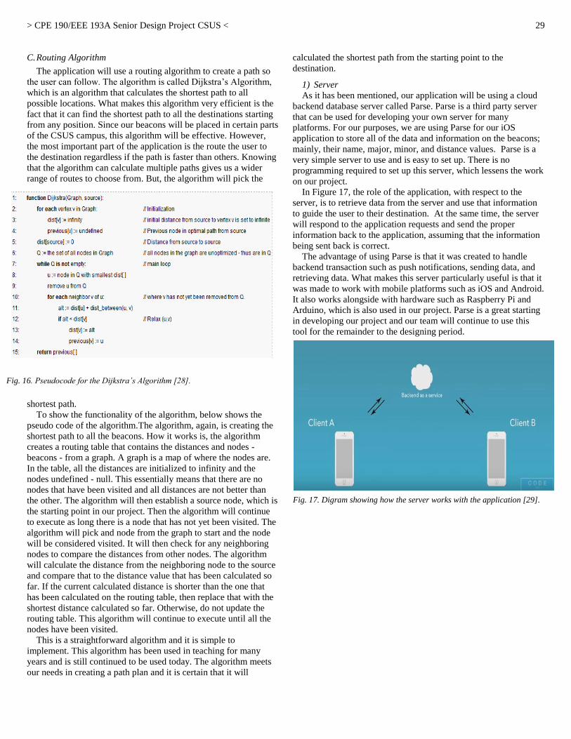
> CPE 190/EEE 193A Senior Design Project CSUS <
29
C. Routing Algorithm
The application will use a routing algorithm to create a path so
the user can follow. The algorithm is called Dijkstra’s Algorithm,
which is an algorithm that calculates the shortest path to all
possible locations. What makes this algorithm very efficient is the
fact that it can find the shortest path to all the destinations starting
from any position. Since our beacons will be placed in certain parts
of the CSUS campus, this algorithm will be effective. However,
the most important part of the application is the route the user to
the destination regardless if the path is faster than others. Knowing
that the algorithm can calculate multiple paths gives us a wider
range of routes to choose from. But, the algorithm will pick the
shortest path.
To show the functionality of the algorithm, below shows the
pseudo code of the algorithm.The algorithm, again, is creating the
shortest path to all the beacons. How it works is, the algorithm
creates a routing table that contains the distances and nodes -
beacons - from a graph. A graph is a map of where the nodes are.
In the table, all the distances are initialized to infinity and the
nodes undefined - null. This essentially means that there are no
nodes that have been visited and all distances are not better than
the other. The algorithm will then establish a source node, which is
the starting point in our project. Then the algorithm will continue
to execute as long there is a node that has not yet been visited. The
algorithm will pick and node from the graph to start and the node
will be considered visited. It will then check for any neighboring
nodes to compare the distances from other nodes. The algorithm
will calculate the distance from the neighboring node to the source
and compare that to the distance value that has been calculated so
far. If the current calculated distance is shorter than the one that
has been calculated on the routing table, then replace that with the
shortest distance calculated so far. Otherwise, do not update the
routing table. This algorithm will continue to execute until all the
nodes have been visited.
This is a straightforward algorithm and it is simple to
implement. This algorithm has been used in teaching for many
years and is still continued to be used today. The algorithm meets
our needs in creating a path plan and it is certain that it will
calculated the shortest path from the starting point to the
destination.
1) Server
As it has been mentioned, our application will be using a cloud
backend database server called Parse. Parse is a third party server
that can be used for developing your own server for many
platforms. For our purposes, we are using Parse for our iOS
application to store all of the data and information on the beacons;
mainly, their name, major, minor, and distance values. Parse is a
very simple server to use and is easy to set up. There is no
programming required to set up this server, which lessens the work
on our project.
In Figure 17, the role of the application, with respect to the
server, is to retrieve data from the server and use that information
to guide the user to their destination. At the same time, the server
will respond to the application requests and send the proper
information back to the application, assuming that the information
being sent back is correct.
The advantage of using Parse is that it was created to handle
backend transaction such as push notifications, sending data, and
retrieving data. What makes this server particularly useful is that it
was made to work with mobile platforms such as iOS and Android.
It also works alongside with hardware such as Raspberry Pi and
Arduino, which is also used in our project. Parse is a great starting
in developing our project and our team will continue to use this
tool for the remainder to the designing period.
Fig. 16. Pseudocode for the Dijkstra’s Algorithm [28].
Fig. 17. Digram showing how the server works with the application [29].

> CPE 190/EEE 193A Senior Design Project CSUS <
30
IX. MARKET REVIEW
Our team evaluated the success our project would have in the
market. The first thing we considered was the target market and the
consumers of our product. Our product would be marketed as a
business to business product and would be aimed at providing
accessibility to colleges. We can also incorporate other places to
our market that would need accessibility for those who are visually
impaired. The team then expanded on the idea to widen our target
market by not just including those who have a disability, but to all
people who have a hard time navigating in different areas. This
allows for a bigger market and a broader range that our product can
be used.
After analyzing the target market, we also looked at other
factors that would impact the success of our product in the market.
One of those factors is competition and similar products. There are
currently a few similar products in our target market, but not very
many. The similar products that we have found were mostly aimed
at providing assistance to those who are disabled. Since we have
broadened our market, we can use this as leverage to give more
people interested in our product. With this market analysis, we can
project how our product will act in the market and see if there is
any potential in selling our product.
Our team now has a clearer idea of how assistive technology is
progressing in the technological market. While observing the
market, we saw the effectiveness of similar products and how it
coincides with the current market for assistive technology. This, in
turn, gave us a different view on how cost effective and reliable
our product can be to possible consumers. From reviewing the
applicable markets, our team has a better understanding of how
economic viability plays a role in developing products. Seeing how
assistive technology is still progressing, our product can contribute
into promoting the awareness of assistive technology. As of now,
the market is lacking a way of implementing a reliable solution
that can provide the convenience desired by an individual. From
observing the trend in this particular market we can see that there
are signs of growth and the opportunity to encourage future
development of dependable technology.
A. Target Market
The markets we are targeting are businesses and organizations
who want to provide accessibility or convenience to an area with
many points of interest. However, our initial target market has
always been to focus on those who are visually impaired at CSUS,
especially since our university contains the most visually impaired
students out of all the CSU campuses in California. Overall, our
market is narrowed down specifically to college campuses who
lack assistive technology. Accessibility, in particular, has a very
wide range of support and services that require specific attention,
especially in the field of marketing. However, our engineering
solution will be directed towards assistive technology that will
provide support for the visually impaired. From what our team has
gathered through research, commercialization of assistive
technology is uncommon and rare, but the impact that assistive
technology can provide for the market is tremendous. Assistive
Technology Partners (ATP) explained that the United States
market for assistive technologies is projected to grow from $39.5
billion in 2010 to $55 billion in 2016 [30]. Considering how
limited the marketing is for this type of technology, this will
simplify the workload needed to reach out to businesses and
organizations that provide assistance to the visually impaired and
have a growing market.
With the growth of the population, it has the potential to fuel the
market in assistive technology because one in five people are
expected to be 65 or older in 2035 [30]. Studies from the Federal
Interagency Forum on Aging Related Statistics estimate in 2008
that 17% of the age 65 or older populations have vision
impairments [31]. This essentially means that aging adults are
more likely to succumb to the prevalence of vision loss due to
aging.
Centers for Disease Control and Prevention (CDC) states that
only half of the estimated 61 million adults in the United States are
classified as being at high risk for serious vision loss [32]. In
addition, the World Health Organization estimated that in 2010,
285 million people are affected by visual impairment [32]. The fact
is that visually impairment continues to be a problem in the
population and is constantly increasing, giving us the notion that a
market for assistive technology has the potential to rapidly grow.
Initially our team had intended on primarily focusing on the
visually impaired and blind individual. After reaching out to local
businesses and schools such as Arden Fair Mall, Regal Cinemas
Natomas, Sacramento International Airport, Cosumnes River
College, CSUS, and Raley’s Supermarket, we were able to become
more familiar with the services that are available for visually
impaired and blind individuals. We noticed that these businesses
Fig. 19. Shows the prevalence rate of blindness in adults [32].
Fig. 18. Shows the population estimate of people who are visually impaired
[31].
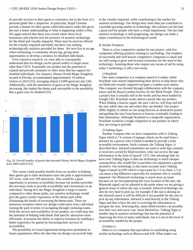
> CPE 190/EEE 193A Senior Design Project CSUS <
31
do provide services to their guest or customers, but in the form of a
personal guide like a chaperone. In particular, Regal Cinemas
provide a feature for their guests called descriptive audio that gives
the user a better understanding of what is happening within a film.
We again noticed that there was a trend where these local
businesses and schools lack the presence of assistive technology
for the blind and visually impaired. There may be services offered
for the visually impaired and blind, but there was nothing
technologically assistive provided for them. We now live in an age
where technology is constantly advancing, giving more
opportunities to develop a solution for disabled individuals. Over extensive research, we were able to conceptually
understand that our design can be spread widely to larger areas
other than CSUS. Essentially our product has the potential to
expand and provide assistance to other areas that has support for
disabled individuals. For instance, Disney World Magic Kingdom,
located in Florida, accommodated approximately 19 million
visitors in 2014 [33], averaging almost 53,000 guest per day [34].
Additionally, with the attendance of guess at the Magic Kingdom
increasing, this makes the theme park susceptible to the possibility
that a guest may be disabled [35].
This venue could possibly benefit from our product in helping
their guests get to their destination since the park is approximately
107 acres, with over 100 attractions. This would be a great
opportunity to promote accessibility because our product provides
the necessary tools to provide accessibility and convenience to an
individual. Seeing how the Magic Kingdom is large in stature
compared to other theme parks, our assistive technology would
give the guest a better experience of the theme park while
eliminating the hassle of traversing the theme park. There are
numerous scenarios where our design could assist every individual
visiting the park in terms of navigating through confusing routes.
With the service and availability of our product, we could step into
the potential of helping individuals find specific attractions more
efficiently. It presents the ability to improve business by enabling a
better experience for guests by increasing their services of
accessibility. The possibility of visual impairment being more prominent in
future populations offers the idea that our design can provide help
to the visually impaired, while contributing to the market for
assistive technology. Our design does more than just contribute to
a possible growing market in technology; this solution can become
a great tool for people who have a visual impairment. The fact that
assistive technology is still progressing, our design can make a
major contribution in the technological world.
B. Similar Products
There is a low competitive market for our project, with few
companies offering products relating to wayfinding. The numbers
of successful and well known competitive companies is small and
are still trying to grow and increase awareness for the need of this
technology. Assisting those who require any means of aid by using
today’s technology is still a new trend.
1) Wayfindr
One main competitor is a company based in London called
Wayfindr who started implementing their device to help those who
are blind and visually impaired navigate a London train station.
This company was formed through collaboration with the company
ustwo and the Royal London Society for the Blind People. This is
a project that is actually still in the works and has been funded by
Google [36]. Wayfindr works almost exactly like our product.
When finding a beacon signal, the user’s device will beep and tell
the user where they are and where they are headed. Our project
differ slightly in which we are using beacons as destination points
and guiding the user from beacon to beacon, eventually leading to
their destination. Although Wayfindr is a nonprofit organization,
Wayfindr would be a tough competitor to our product in which
they are trying to provide.
2) Talking Signs
Another company that we have competition with is Talking
Signs which is “A system of signage which can be read from a
distance by a person who is blind is needed to provide a truly
accessible environment. Such a system, the Talking Signs: is
described here. Infrared transmitters are used to send sign contents
to receivers carried by blind travelers, who can receive the sign
information in the form of speech” [37]. One advantage that we
have over Talking Signs is that our technology is much cheaper
causing those who would like to purchase our equipment a greater
incentive. Our technology is also more accurate since Talking
Signs is based on GPS which is inaccurate by 2-3 m, these 2-3 m
can mean a big difference especially for someone who is visually
impaired. Our Bluetooth technology is much more accurate
because we are not pinpointing the exact location of the user, the
Bluetooth signal can be adjusted to the point where we are giving a
general sense of where the user is located. Infrared technology can
also be very hard to pick up, for example if the sun is shining on
the infrared source it will be difficult if not possible for the user to
pick up any information. Infrared is used heavily in the Talking
Signs and that is how the user is receiving the information to
navigate the user. Knowing this, many blind travelers can possibly
lose their way and worst case, harm themselves. Talking Signs is
another step in assistive technology that has the potential of
improving the lives of many individuals, but it is not at the level of
accessibility needed by the people.
3) Indoo.rs
Indoo.rs is a company that specializes in wayfinding using
similar technology such as iBeacon and iOS. What makes our
Fig. 20. Overall number of guests that attended Disney World Magic Kingdom
from 2009 to2014 [35].
> CPE 190/EEE 193A Senior Design Project CSUS <
32
product different from Indoo.rs is that they only centralize their
product to work indoors to where our product can be used both
indoors and outdoors. Our product is more effective at a
geographical level because we are using our technology to guide
people outdoors, where possible routes are unpredictable compared
to being indoors. What makes them greatly competitive is they are
achieving the same functionality as our design and using the same
technology. However, Indoo.rs is currently selling their product for
a standard package at $499 per month while their professional
package is priced at $999 per month [38]. The prices for the
product are at reasonable ranges, but our product can provide more
service to the consumer. Again, our product can function indoors
and outdoors, giving the consumer their money’s worth. Having
this extra service gives us a strong leverage on Indoo.rs because we
are targeting a wider problem. We want to further increase a
person’s independency outside the public. Indoo.rs is heading in
the right direction with assistive wayfinding, but our product is
furthering its development and steadily improving assistive
technology.
4) Projections
At the moment, we are implementing our project using only a
few devices. The first device is a Raspberry Pi which includes a
Wi-Fi dongle, a Bluetooth 4.0 dongle, and a 2.8” touchscreen. Our
second device is an iPhone. The last device includes the beacons
that we are placing around the campus. Theoretically, if we were to
market the product, the pricing would be the cost of how many
components the consumer would like to purchase for their
business. The pricing would be broken down as follows: the cost of
the portable devices, the cost of the software for the iPhone, and
the cost of the beacons which will depend on how much area they
would like to cover with the beacons. Additional fees can be for
installation of the product and maintenance of product. Our
portable device would be cheap to make, especially while using the
Raspberry Pi. The only thing needed for the application is the cost
of the application development kit which makes the app a very low
cost product. The cost of the beacons will depend on our team
producing the beacons or buying them from another vendor like
Estimote which can range from $15 to $40 a beacon. This makes
our product very cost effective and has great potential for making
profit. Taking into account the number of schools, theme parks,
shopping centers, and other places our project can be used, shows
that there is a big market for our product. If there is an increase of
the need for accessibility and convenience for these places, then
our product could trend and become a feature that all businesses
will want. In a sense, our product would act like an alarm company
in terms of selling components and providing a service. At the
moment, our project is implemented on iOS devices. According to
Statista, there was “44.53 million iPhone users in the United
States” in 2012 [39]. This would allow our product to be accessible
to a big population. By providing new technology that will provide accessibility and
convenience to different places, the project can become successful
and become a standard to have in providing customers this type of
service. This will benefit those who are visually impaired and
make finding places easier for people. Promoting the concept of
providing accessibility to these different places and placing
importance on accessibility can make this a priority for businesses,
which will place us in the forefront of this market.
X. FUTURE IMPROVEMENTS AND IMPLEMENTATION
Throughout the senior design period, we were able to achieve
the goal guiding a user from on building to another using our
engineering skill sets. However, since time was a major factor in
our project, we were limited in incorporating features that could
benefit our project. Hopefully, a future group can further improve
upon our design and make it more efficient for future users.
A. Database migration
During our second phase of our design, we were notified by
Parse that they will no longer be continuing their services and will
migrate to a different database backend. If this project were to be
further improved upon, the server will need to migrate to a
different server or find an alternative third party backend to store
all the beacon information. Another solution to this issue is to
develop a new server that incorporates the same functionalities as
the Parse server. However, by using a different server, you will
have to use different source code to access the new database. The
method of accessing the database is the same, but the code to
actually access the database will be different depending on the
server one will utilize.
B. Management on the Beacons
As of right now, the Estimote beacons are using a CR2477 battery
to power the device. With appropriate enough settings, the beacon
can last up to 4 to 5 years. Unfortunately as of now, we have no
way of determining the battery life of the beacon without
approaching the beacon with the Estimote application to verify the
battery life. If this project continues to be further improved upon, a
group can develop a management system that can determine the
battery life of a beacon. This system will give the person, who is
maintaining and managing the beacons, an easier time and it would
lessen the hassle of having to approach each beacon to check the
battery life. We would also like to be able to make sure our
beacons functioning correctly and manage the beacons in different
situations like extreme weather that may affect the beacons.
Seeing if the beacons are working correctly and not tampered with
is valuable information the project may need to be fully
implemented in a campus. An alternative way of improving beacon
management would be to design and implement our own beacons
and developing a platform that will manage the system of beacons.
C. Suitable Replacement for Battery
As is was already mentioned, the Estimote beacons are using a
CR2477 battery that powers the device for up to 4 to 5 years
depending on the power distribution settings. A future group can
develop an efficient solution where they can replace the CR2477
battery in the beacons. One solution that can replace the CR2477
battery is solar power. During the day, the beacons can be power
using solar power when the beacons are actually being used while
at night the beacons will no longer be powered on to be used. As
long power is being saved on the beacons, any solution to battery
power will greatly benefit the project.
D. Modifying the Hardware Case
We have a case enclosure that encase all of our hardware for the
visually impaired – Raspberry Pi 2, battery pack, and touch screen.
Currently, our devise is portable, but our case can be further

> CPE 190/EEE 193A Senior Design Project CSUS <
33
reduced, make it lighter and more portable. What a feature team
can do to improve on the case is to make the dimensions small
enough where the hardware can still fit and be portable. Also, the
case is much heavier than it should be, therefore adding more
weight for the user utilizing our hardware. If possible, making the
case lighter would be a plus for future implementation.
E. Reducing Power for Portable Device
The battery for our hardware device lasts approximately 7
to 8 hours which is plenty of time for a user to use the
device. The problem is that the device would have to be
charged every day that a person uses it. An area of
improvement would be to increase the battery life. To reduce
the amount of battery consumption, we can further tweak the
Raspberry Pi that we are using for the hardware device and
make sure it is only using the resources it needs. We can also
invest in a better battery pack that has more milliamp hour
(mAh).
F. Espeak Function
While creating the audio functionality for the portable
device, the team wanted to use at text-to-speech function that
will allow users to easily understand the instruction prompts.
The library we decided to use is Espeak which allowed us to
use text to speech in our python code.
The Espeak library works, but is not as appeasing to the
person using it. While talking to Gene Lozano, Jr., a
Disability Management Counselor at SSWD, he suggested
out speech functionalities to sound as human as possible and
that a female voice is preferred because it is easier to
understand and listen to. The Espeak function in the portable
device could sound better and easier for the user, however
this is a function that even Google, Apple, and Microsoft are
still trying to improve on. There are not very many open
source text-to-speech options available for our hardware and
some take more time to incorporate to our device. Ways that
we can improve on our speech output would be to create our
own .wav audio files to output our speech which will be as
natural as we can get to the human voice or we can invest
more time in searching for other text-to-speech options
available. This would provide users a better experience.
XI. CONCLUSION
Conclusively, we were able to complete our senior design
project and achieve the goal of assisting the visually impaired
navigate through the CSUS campus. With the available technology
that we are currently exposed to, we were able to make this project
possible. We were able to design a portable device that allows a
visually impaired student to navigate through the campus
independently using the hardware device and features that we
designed. Along with the hardware device, we designed an iOS
application that will also accommodate the new and incoming
students that have no familiarity of the CSUS campus layout. With
the functionality of the Estimote beacons and Parse server, we
were able to use their functionality, in unison with both the mobile
application and portable device, to guide the user through a series
of beacons through preset instructions to their desired destination.
With the Raspberry Pi 2’s processing power, we were able to
access its powerful features and we were able to enable Bluetooth
communication between the Raspberry Pi and Estimote beacons,
while at the same time communicating with the database using
RESTful API. Similarly, the iOS application is able to
communicate with the Estimote beacons using existing API
libraries designed for iBeacon technology, making developing the
application easier. At the same time, the Parse tutorial and
documentation allowed us to make communication possible
between the iOS application and the database. In our senior design process, we needed to continuously modify
and improve our project where it can be efficiently used without
complications. When going through the senior design process, we
were able to understand our project at a more technical and
thoughtful level. We designed our project on the basis of the
engineering concepts that we learned in our college career. We
applied concepts such as creating a design idea, feature set, work
breakdown structure, risk assessment, device test plan, and other
concepts to develop the project in an organized way. We made
sure, through rigorous testing, that our project is successful at
guiding a student from one place to another. We were able to
verify that our hardware can guide the user to their destination
using Bluetooth signals from the beacons, which has a set of
instructions particular to the beacon. With the addition of audio
output, we were able to orally tell the user where to go versus
reading a set of instructions on the hardware. We were able to use
the Estimote beacons to our advantage by configuring the settings
to accommodate a certain area of the CSUS campus to help further
guide the user from one beacon another. The database made
wayfinding possible with its feature to store informational data on
the beacons, making it possible to differentiate beacons from one
another. For new and incoming students, the mobile application
will perform the same functionality as the portable device, but
there will be readable text and audio output for them to read and
listen to as they walk to their destination. Through the engineering
concepts we developed during the senior design process, we were
able to finalize our project and make our project deployable for
future users. It was a great milestone from when we were actually able to
guide the user with our two platform devices while implementing
and utilizing Bluetooth and WiFi. Although we accomplished our
goal in assisting the user with our senior design project, we
pondered on how we can take this project to the next level. That's
why there's a lot to to consider when moving forward with a senior
design project. One of the main things we wanted to keep in mind
is how can we improve upon our project with the limited time that
we have in our course. From keeping in close contact with the
SSWD we had the opportunity to obtain a good understanding on
who we were trying to help. In order to really achieve our goal, we
implemented various testing to really obtain viable data to really
back up our final product. It was really nice how we were able to
apply the concepts that we learned within our program such as the
routing algorithm and responding to the common database. Within
our effort of actually making an impact with our target users, our
device definitely has the potential to make a difference. After
actually producing a deployable prototype, we saw how we could
expand upon this project such as how it could be applied to places
such as theme parks and museums. We are hoping during our final
> CPE 190/EEE 193A Senior Design Project CSUS <
34
presentation in late May of 2016 that students and faculty will have
the opportunity to see how our project promotes accessibility and
convenience to a wide range of students and how new technology
can be applied to further create more assistive technology needed
in our world.
XII. REFERENCES
[1] Calstate.edu, "Services to Students with Disabilities | Student Academic Support | CSU", 2016. [Online]. Available:
http://www.calstate.edu/sas/disabilities.shtml. [Accessed: 30- Jan-
2016]. [2] F. Andrew A. Dahl, "Blindness: Get Facts About Causes of Vision
Loss", MedicineNet, 2016. [Online]. Available:
http://www.medicinenet.com/blindness/article.htm. [Accessed: 30- Jan- 2016].
[3] Who.int, "WHO | Visual impairment and blindness", 2016. [Online].
Available: http://www.who.int/mediacentre/factsheets/fs282/en/. [Accessed: 30- Jan- 2016].
[4] Afb.org, "Technology Resources for People with Vision Loss -
American Foundation for the Blind", 2016. [Online]. Available: http://www.afb.org/info/living-with-vision-loss/using-technology/12.
[Accessed: 30- Jan- 2016].
[5] Nfb.org, "Free Cane Program | National Federation of the Blind", 2016. [Online]. Available: https://nfb.org/free-cane-program. [Accessed: 30-
Jan- 2016].
[6] M. Peck, "RFID Tags Guide the Blind", Spectrum.ieee.org, 2016. [Online]. Available: http://spectrum.ieee.org/biomedical/devices/rfid-
tags-guide-the-blind. [Accessed: 30- Jan- 2016].
[7] Csols.com, 2016. [Online]. Available: http://www.csols.com/wordpress/wp-
content/uploads/2012/12/14757828_s.jpg. [Accessed: 30- Jan- 2016].
[8] Ustwo.com, 2014. [Online]. Available: https://ustwo.com/blog/designing-wayfindr/. [Accessed: 30- Jan- 2016].
[9] 2016. [Online]. Available:
http://delivery.acm.org/10.1145/2670000/2661380/p217-williams.pdf?ip=130.86.97.26&id=2661380&acc=ACTIVE%20SERVI
CE&key=F26C2ADAC1542D74%2EF8B29279A7E50DFA%2E4D470
2B0C3E38B35%2E4D4702B0C3E38B35&CFID=578768480&CFTOKEN=93729307&__acm__=1454038780_80e6ee41a12192f4e4957ca391
d3244f. [Accessed: 30- Jan- 2016].
[10] 2016. [Online]. Available: http://www.eltis.org/sites/eltis/files/case-studies/documents/fin-noppa_1.pdf. [Accessed: 30- Jan- 2016].
[11] 2015. [Online]. Available: https://ustwo.com/blog/validating-wayfindr/.
[Accessed: 19-Sep-2015]. [12] 2015. [Online]. Available: http://www.ms.unimelb.edu.au/~moshe/620-
261/dijkstra/dijkstra.html. [Accessed: 19-Sep-2015].
[13] 2015. [Online]. Available: https://ustwo.com/blog/validating-wayfindr/. [Accessed: 19-Sep-2015].
[14] 2015. [Online]. Available: http://www.geeksforgeeks.org/greedy-algorithms-set-6-dijkstras-shortest-path-algorithm/. [Accessed: 19-Sep-
2015].
[15] 2015. [Online]. Available: http://www.geeksforgeeks.org/greedy-algorithms-set-6-dijkstras-shortest-path-algorithm/. [Accessed: 19-Sep-
2015].
[16] Developer.apple.com, 'The Swift Programming Language (Swift 2): About Swift', 2015. [Online]. Available:
https://developer.apple.com/library/prerelease/ios/documentation/Swift/
Conceptual/Swift_Programming_Language/index.html. [Accessed: 19- Sep- 2015].
[17] Python.org, "Welcome to Python.org", 2016. [Online]. Available:
https://www.python.org/doc/essays/blurb/. [Accessed: 31- Jan- 2016].Available: Rlsb.org.uk, "Wayfindr | RLSB", 2016. [Online].
Available: http://www.rlsb.org.uk/tech-hub/wayfindr. [Accessed: 25-
Feb- 2016]. [18] Bluetooth.com, 'Fast Facts | Bluetooth Technology Website', 2015.
[Online]. Available: http://www.bluetooth.com/Pages/Fast-Facts.aspx.
[Accessed: 19- Sep- 2015]. [19] Bing.com, 2015. [Online]. Available:
http://www.bing.com/th?id=JN.IZR8LSGhaid2bt6bfosVOQ&pid=15.1
&P=0&w=300&h=300. [Accessed: 19- Sep- 2015].
[20] Raspberry Pi, 'Raspberry Pi 2 Model B', 2015. [Online]. Available:
https://www.raspberrypi.org/products/raspberry-pi-2-model-b/.
[Accessed: 28- Nov- 2015]. [21] "raspberry pi 2 - Google Search", Google.com, 2016. [Online].
Available:
https://www.google.com/search?q=raspberry+pi+2&source=lnms&tbm=isch&sa=X&ved=0ahUKEwjEppHvq7jMAhUPyGMKHT50AUkQ_AU
ICigE&biw=1440&bih=730&dpr=1#imgrc=gGwJrS6MxEpiBM%3A.
[Accessed: 01- May- 2016].Edimax.com, 'EDIMAX Technology - Official Website - N150 - N150 Wi-Fi Nano USB Adapter, Ideal for
Raspberry Pi', 2015. [Online]. Available:
http://www.edimax.com/edimax/merchandise/merchandise_detail/data/edimax/global/wireless_adapters_n150/ew-7811un. [Accessed: 28- Nov-
2015].
[22] Edimax.com, 'EDIMAX Technology - Official Website - N150 - N150 Wi-Fi Nano USB Adapter, Ideal for Raspberry Pi', 2015. [Online].
Available:
http://www.edimax.com/edimax/merchandise/merchandise_detail/data/edimax/global/wireless_adapters_n150/ew-7811un. [Accessed: 28- Nov-
2015].
[23] A. Industries, "PiTFT Plus 320x240 2.8 TFT + Capacitive Touchscreen - Assembled [Pi 2, Model A+ / B+] ID: 2423 - $44.95 : Adafruit
Industries, Unique & fun DIY electronics and kits", Adafruit.com, 2016.
[Online]. Available: https://www.adafruit.com/products/2423. [Accessed: 02- May- 2016].
[24] Team Icarus. Charts and Diagrams. 2015.
[25] Team Icarus. Pictures. 2015. [26] Team Icarus. Charts and Diagrams. 2015.
[27] Team Icarus. Charts and Diagrams. 2015.
[28] H. Thomas Grossmann (Overall), "Dijkstra Algorithm: Short terms and Pseudocode", Gitta.info, 2016. [Online]. Available:
http://www.gitta.info/Accessibiliti/en/html/Dijkstra_learningObject1.ht
ml. [Accessed: 04- May- 2016]. [29] "CodeWithChris", YouTube, 2016. [Online]. Available:
https://www.youtube.com/user/CodeWithChris. [Accessed: 04- May-
2016]. [30] C. Casey, "Assistive technologies market growing rapidly - CU Denver
Today", CU Denver Today, 2012. [Online]. Available:
http://cudenvertoday.org/assistive-technologies-market-growing-at-
rapid-rate/. [Accessed: 25- Feb- 2016].
[31] Cdc.gov, "National Data | Data & Statistics | VHI | CDC", 2016.
[Online]. Available: http://www.cdc.gov/visionhealth/data/national.htm. [Accessed: 22- Feb- 2016].
[32] C. Katia Hetter, "World's top 25 amusement parks", CNN, 2016.
[Online]. Available: http://www.cnn.com/2015/06/03/travel/feat-most-popular-theme-parks-world-2014/. [Accessed: 23- Feb- 2016].
[33] C. Katia Hetter, "World's top 25 amusement parks", CNN, 2016.
[Online]. Available: http://www.cnn.com/2015/06/03/travel/feat-most-popular-theme-parks-world-2014/. [Accessed: 23- Feb- 2016].
[34] P. Reikofski, "How Many People Go To Disney World Every Day?", Temporary Tourist, 2015. [Online]. Available:
http://temporarytourist.com/how-many-people-go-to-disney-world-
every-day/. [Accessed: 25- Feb- 2016]. [35] Statista, "Magic Kingdom Walt Disney World Florida attendance 2009-
2014 | Statistic", 2016. [Online]. Available:
http://www.statista.com/statistics/232966/attendance-at-the-walt-disney-world-magic-kingdom-theme-park/. [Accessed: 25- Feb- 2016].
[36] Rlsb.org.uk, "Wayfindr | RLSB", 2016. [Online]. Available:
http://www.rlsb.org.uk/tech-hub/wayfindr. [Accessed: 25- Feb- 2016]. [37] J. Brabyn, W. Crandall and W. Gerrey, "Talking signs: a remote
signage, solution for the blind, visually impaired and reading disabled",
Proceedings of the 15th Annual International Conference of the IEEE Engineering in Medicine and Biology Society.
[38] Indoo.rs, "indoo.rs pricing", 2016. [Online]. Available:
http://indoo.rs/pricing/. [Accessed: 25- Feb- 2016]. [39] Statista, "Number of iPhone users in the US 2012-2015 | Statistic", 2016.
[Online]. Available: http://www.statista.com/statistics/232790/forecast-
of-apple-users-in-the-us/. [Accessed: 25- Feb- 2016]. [40] Team Icarus. Charts and Diagrams. 2016.
[41] Team Icarus. Pictures. 2016.
[42] Team Icarus. Charts and Diagrams. 2016. [43] Team Icarus. Charts and Diagrams. 2016.
[44] Team Icarus. Charts and Diagrams. 2016.
[45] Team Icarus. Charts and Diagrams. 2016. [46] Team Icarus. Charts and Diagrams. 2016.

> CPE 190/EEE 193A Senior Design Project CSUS <
35
[47] Team Icarus. Charts and Diagrams. 2016.
[48] Sketchappsources.com, 2016. [Online]. Available:
http://www.sketchappsources.com/resources/source-image/estimote-ibeacons-devinmancuso.png. [Accessed: 26- Mar- 2016].
[49] "The Hitchhikers Guide to iBeacon Hardware: A Comprehensive Report
by Aislelabs (2015) - Aislelabs", Aislelabs, 2016. [Online]. Available: http://www.aislelabs.com/reports/beacon-guide/. [Accessed: 26- Mar-
2016].
[50] "The Hitchhikers Guide to iBeacon Hardware: A Comprehensive Report by Aislelabs (2015) - Aislelabs", Aislelabs, 2016. [Online]. Available:
http://www.aislelabs.com/reports/beacon-guide/. [Accessed: 26- Mar-
2016]. [51] Team Icarus. Pictures. 2016
[52] Team Icarus. Pictures. 2016.
[53] Team Icarus. Charts and Diagrams. 2016 [54] Team Icarus. Charts and Diagrams. 2016.
[55] Team Icarus. Charts and Diagrams. 2016.
GLOSSARY
1) Android – Is a mobile operating system (OS) based on
the Linux kernel and currently developed by Google.
2) Bluetooth – Is a wireless technology standard for
exchanging data over short distances (using short-
wavelength Ultra High Frequency (UHF) radio waves in
the Industrial, Scientific, and Medical (ISM) band from
2.4 to 2.485 GHz).
3) Braille – a tactile writing system used by people who are
blind and low vision.
4) Braille Embosser - Is an impact printer that renders text
as tactile braille cells.
5) C – Is a general-purpose, imperative computer
programming language, supporting structured
programming, lexical variable scope and recursion, while
a static type system prevents many unintended operations.
6) Cloud – A database that typically runs on a cloud
computing platform.
7) Computer bug – An error, flaw, failure, or fault in a
computer program or system that causes it to produce an
incorrect or unexpected result, or to behave in unintended
ways.
8) Computer crash – When a computer program, such as a
software application or an operating system, stops
functioning properly.
9) Database – Is an organized collection of data. It is the
collection of schemes, tables, queries, reports, views, and
other objects
10) Debugging – The process of finding and resolving bugs
or defects that prevent correct operation of computer
software or a system.
11) Dijkstra’s Algorithm – Created by Edsger W. Dijkstra, it
is an algorithm for find the shortest paths between nodes
in a graph.
12) Disease Control and Prevention – Is the leading national
public health institute of the United States.
13) Estimote – Small wireless sensors that can be attached to
any location or object. They broadcast tiny radio signals,
which a smartphone can receive and interpret, unlocking
micro-location and contextual awareness.
14) Global Positioning System (GPS) – Is a space-based
navigation system that provides location and time
information in all weather conditions, anywhere on or
near the Earth where there is an unobstructed line of sight
to four or more GPS satellites.
15) iBeacon – Is a protocol standardized by Apple and
introduced at the Apply Worldwide Developers
Conference in 2013. They use Bluetooth low energy
proximity sensing to transmit a Universally Unique
Identifier (UUID) picked up by a compatible application
or operating system (OS).
16) Integrated Development Environment (IDE) – Is a
software application that provides comprehensive
facilities to computer programmers for software
development.
17) iOS – Is a mobile operating system created and developed
by Apple and distributed exclusively for Apple hardware.
18) Host – A server dedicated to hosting a service or services
for users.
19) Java – Is a general-purpose computer programming
language that is concurrent, class-based, object-oriented,
and specifically designed to have as few implementation
dependencies as possible.
20) Nodes – A basic unit used in computer science. Nodes are
devices or data points on a larger network. Devices such
as a personal computer, cell phone, or printer are nodes.
When defining nodes on the internet, a node is anything
that has an IP address. Nodes are individual parts of a
larger data structure, such as linked lists and tree data
structures. Nodes contain data and also may link to other
nodes. Links between nodes are often implemented by
pointers.
21) Objective-C – Is a general-purpose object-oriented
programming language that adds Smalltalk-style
messaging to the C Programming Language.
22) Received Signal Strength Indicator – Is a measurement
of the power present in a received radio signal.
23) Server – is both a running instance of some software that
is capable of accepting requests from clients, and the
computer that executes such software.
24) Swift – Is a multi-paradigm, compiled programming
language created by Apple for iOS, OS X, and watchOS
development.
25) User Interface (UI) – Is everything designed into an
information device with which a human being may
interact -including display screen, keyboard, mouse, light
pen, the appearance of a desktop, illuminated characters,
help messages - and how an application program or a
Web site invites interaction and responds to it.
26) WiFi - Is a local area wireless computer networking
technology that allows electronic devices to a network,
mainly using the 2.4 gigahertz (GHz) ultra-high frequency
(UHF) and 5 GHz super high frequency (SHF) industrial,
scientific, and medical (ISM) radio bands.
27) Xcode – A program compiler developed by Apple that
allows programmers to create computer or mobile based
application.

> CPE 190/EEE 193A Senior Design Project CSUS <
A-1
APPENDIX A. USER MANUAL
Project Icarus offers two different devices for users. The mobile application offers wayfinding help for anyone who needs it while the
hardware device is suited towards those who are visually impaired and need more detailed guidance.
A. Mobile Application
1) Downloading the Application
The application is still in development phase and not yet on the market. To get the application, the user must contact Team Icarus for
more information. The application will have to be installed to an iOS device using Xcode. The program compiles the application and then
installs it straight into the device.
2) Running the Application
Once the application is installed on the device, the user may now run it. Upon entering the application, the user will be greeted with a
starting screen prompting the user to use the app from a button. The user will need to enable a Wi-Fi connection or mobile internet
connection and enable Bluetooth capabilities on their mobile phones. Once the application has an internet connection and has Bluetooth
on, the user can begin searching for beacons by pressing the continue button. The mobile application will then begin to search for a
starting beacon. Once a starting beacon is found, the user will be prompted to choose a destination among the predetermined paths
available. The application will then guide the user to their destination by listing sets of instructions on how to get from each beacon to the
next beacon. When each beacon is reached the application will update with new instructions to get to the next beacon. The user will be
notified that they have reached their destination once they receive the destination beacon signal.
3) Audio
Audio assisted instructions are automatically incorporated with the application. The audio instructions follow exactly what is stated
on the screen and are not needed, but add convenience.
4) Settings
There are currently no settings for the application at the moment.
B. Hardware Device
1) Putting on the Hardware Device
The deployable prototype for the hardware device currently features a belt/strap design. The user must first adjust the belt to their
preference and move the hardware device harness to the side of the non-dominant hand. Then the user can then continue to attach the
shoulder strap to secure the belt around the body. Once the belt is secured, the hardware device can be attached to the hardware harness.
2) Running the Hardware Device
The hardware device must first be powered by attaching the power cable from the battery to the hardware device. The device will then
boot up with the on screen application. Once the application is booted on the device, the user may now use it. Upon entering the
application, the user will be greeted with a starting screen prompting the user to continue by pressing a button. A WiFi connection will be
needed to run the application. The hardware device will then begin to search for a starting beacon. Once a starting beacon is found, the
user will be prompted to choose a destination among the predetermined paths available. The application will then guide the user to their
destination by listing sets of instructions on how to get from each beacon to the next beacon. When each beacon is reached the application
will update with new instructions to get to the next beacon. The user will be notified that they have reached their destination once they
receive the destination beacon signal.
3) Audio
Audio assisted instructions are automatically incorporated with the application. The audio instructions follow exactly what is stated on
the screen.
4) Settings
There are currently no settings for the application at the moment.

> CPE 190/EEE 193A Senior Design Project CSUS <
B-1
APPENDIX B. HARDWARE
C. Portable Device
Once we’ve established the necessary components required to work
the first phase of the senior design, it is important to now look forward
for the work required for the next semester. Our team not only plans on
improving on the prototype but we also plan on adding to the
project. During the spring semester we plan on actually testing
primarily on the outside rather than in the hallways of Riverside. This
will ensure that our project operates correctly in the desired
environment.
One of the areas that we will be looking into is voice
recognition. This was a plan that our group discussed that should be a
feature for the hardware for the visually impaired. We plan on having
buttons most likely for on and off mode. But the general form of user
communication to the device is through voice.
Since we will be testing outside we thought it would be great idea to
begin data collecting in the second semester. The data that we plan on
collecting is how the device behaves in certain areas of the campus; we
also wanted to observe how the Raspberry Pi operates with students
walking around. One of the things that we want to account for is line of
sight and interference. We want to catch these issues early on and that
way we can mitigate the problem and ensure that the user gets to their
desired destination. We can track the signal strength values and from
these values we can observe how the signals are being received from
the Estimote beacons to the Bluetooth adapter of the Raspberry Pi. We
will also have to test the Raspberry Pi’s Wi-Fi capability outside
ensuring that we will be able to get internet access outside the
buildings.
During data testing, we also have the opportunity to implement one
of our countermeasures for the user, which is to notify them that they
are leaving the range of which they require them to have access to the
network. This will require us grabbing data from the WiFi adapter that
we are using to access the data from the Parse server. We saw that there
is a way to grab characteristic data from the Edimax adapter. The
notification should let the user know that they are leaving the region of
normal operation. Our device requires a network connection to operate
properly. Without the connection, they have no routing directions. We
may also place excess beacons around the boundary that a user should
not be going to and if the beacon is found, then there will be a
notification to let the user know that they are leaving the operating area.
This topic actually goes into the next issue of having another
countermeasure. Although we want to be expecting the best case
scenario, this is not the case when testing. We still want to enable the
user to have routing information if there is no network communication.
We will be looking on giving the Raspberry Pi additional memory that
way it can carry backup routing data. The way this would work is if the
Raspberry Pi reaches several attempts to connect to the network, then it
will switch to “backup mode” where it will begin to access data from the backup routing data. This was actually part of our mitigation
concepts that was introduced during our risk assessment section. Having this feature enables a safe and efficient device provided for the
user.
The Raspberry Pi that we are currently working with is encased in a plastic case that is fairly compact. During the next semester we
will be looking on designing on how we will make the device wearable. We will be considering areas such as where the primary
component will be placed with respect to the user. We were planning on having the device placed in the front area of the user. A possible
implementation is connecting the wearable to the user through a strap. We will be considering size of the component.
When testing the Raspberry Pi we normally have it plugged through a mini USB cable to the wall. The user will need to be mobile, so
we will be looking at what kind of external power supply that the Raspberry Pi can use. We do not want the battery pack to be too big, but
we also want to provide long lasting service.
Fig. 21. Wearable Device Flowchart [40].
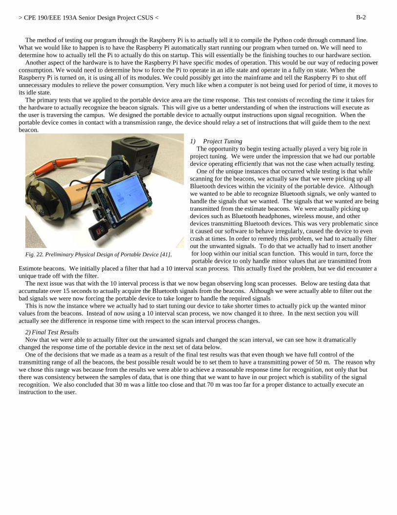
> CPE 190/EEE 193A Senior Design Project CSUS <
B-2
The method of testing our program through the Raspberry Pi is to actually tell it to compile the Python code through command line.
What we would like to happen is to have the Raspberry Pi automatically start running our program when turned on. We will need to
determine how to actually tell the Pi to actually do this on startup. This will essentially be the finishing touches to our hardware section.
Another aspect of the hardware is to have the Raspberry Pi have specific modes of operation. This would be our way of reducing power
consumption. We would need to determine how to force the Pi to operate in an idle state and operate in a fully on state. When the
Raspberry Pi is turned on, it is using all of its modules. We could possibly get into the mainframe and tell the Raspberry Pi to shut off
unnecessary modules to relieve the power consumption. Very much like when a computer is not being used for period of time, it moves to
its idle state.
The primary tests that we applied to the portable device area are the time response. This test consists of recording the time it takes for
the hardware to actually recognize the beacon signals. This will give us a better understanding of when the instructions will execute as
the user is traversing the campus. We designed the portable device to actually output instructions upon signal recognition. When the
portable device comes in contact with a transmission range, the device should relay a set of instructions that will guide them to the next
beacon.
1) Project Tuning
The opportunity to begin testing actually played a very big role in
project tuning. We were under the impression that we had our portable
device operating efficiently that was not the case when actually testing.
One of the unique instances that occurred while testing is that while
scanning for the beacons, we actually saw that we were picking up all
Bluetooth devices within the vicinity of the portable device. Although
we wanted to be able to recognize Bluetooth signals, we only wanted to
handle the signals that we wanted. The signals that we wanted are being
transmitted from the estimate beacons. We were actually picking up
devices such as Bluetooth headphones, wireless mouse, and other
devices transmitting Bluetooth devices. This was very problematic since
it caused our software to behave irregularly, caused the device to even
crash at times. In order to remedy this problem, we had to actually filter
out the unwanted signals. To do that we actually had to insert another
for loop within our initial scan function. This would in turn, force the
portable device to only handle minor values that are transmitted from
Estimote beacons. We initially placed a filter that had a 10 interval scan process. This actually fixed the problem, but we did encounter a
unique trade off with the filter.
The next issue was that with the 10 interval process is that we now began observing long scan processes. Below are testing data that
accumulate over 15 seconds to actually acquire the Bluetooth signals from the beacons. Although we were actually able to filter out the
bad signals we were now forcing the portable device to take longer to handle the required signals
This is now the instance where we actually had to start tuning our device to take shorter times to actually pick up the wanted minor
values from the beacons. Instead of now using a 10 interval scan process, we now changed it to three. In the next section you will
actually see the difference in response time with respect to the scan interval process changes.
2) Final Test Results
Now that we were able to actually filter out the unwanted signals and changed the scan interval, we can see how it dramatically
changed the response time of the portable device in the next set of data below. One of the decisions that we made as a team as a result of the final test results was that even though we have full control of the
transmitting range of all the beacons, the best possible result would be to set them to have a transmitting power of 50 m. The reason why
we chose this range was because from the results we were able to achieve a reasonable response time for recognition, not only that but
there was consistency between the samples of data, that is one thing that we want to have in our project which is stability of the signal
recognition. We also concluded that 30 m was a little too close and that 70 m was too far for a proper distance to actually execute an
instruction to the user.
Fig. 22. Preliminary Physical Design of Portable Device [41].

> CPE 190/EEE 193A Senior Design Project CSUS <
B-3
Figure 23 shows the long intervals of the hardware device at 30 m, which shows the amount of samples taken with respect to time.
In Figure 24, the line graph represents the same response times recorded in Figure 23, but at a different region of 50 m.
Fig. 23. Long interval scan at 30 m [42].
Fig. 24. Long interval scan at 50 m [43].

> CPE 190/EEE 193A Senior Design Project CSUS <
B-4
Similarly to Figure 23 and 24, it displays the response times at different intervals, but at 70 m.
In Figure 26, the line graph represents the same 30 m response time, but the difference is that the intervals are shorter with respect to time.
Fig. 25. Lomg interval scan at 70 m [44].
Fig. 26. Short interval scan at 40 m [45].
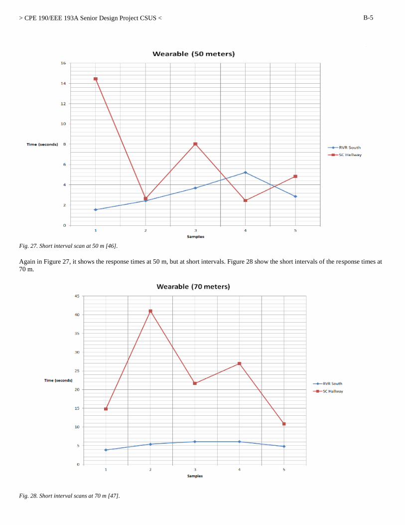
> CPE 190/EEE 193A Senior Design Project CSUS <
B-5
Again in Figure 27, it shows the response times at 50 m, but at short intervals. Figure 28 show the short intervals of the response times at
70 m.
Fig. 27. Short interval scan at 50 m [46].
Fig. 28. Short interval scans at 70 m [47].

> CPE 190/EEE 193A Senior Design Project CSUS <
B-6
D. Beacons
The beacon fulfills the regional beacon awareness feature of the project which allows us to associate a beacon with a certain area.
Beacons emit a BLE signal that advertises data. This data consists of a UUID, major and minor value, and RSSI. This data can be used to
differentiate the beacons and help determine what area a user is in depending on where we have selectively placed the beacon. Our mobile
application and hardware device scans for specific “starting beacons”. Once they are found, a user can select a “destination beacon” and
will then be guided to each beacon along the path to their destination with predetermined instructions. When a user gets to each beacon,
the user will be notified and will be guided to the next beacon until they reach their destination. Without the beacons, our devices have no way of knowing where a user is and cannot guide a user as they navigate place to place. The
beacons are what essentially give a user interaction to the environment with the device and allows for a type of real time guidance.
1) Features/Components
The purpose of the region beacon awareness feature is to allow the devices we will be implementing a way to have spatial intelligence.
To provide the feature, we used iBeacon technology which both the
mobile application and hardware device can detect. iBeacon technology
uses BLE also known as Bluetooth Smart to transmit data. The Bluetooth
signal uses low power and transmits at a different frequency than regular
Bluetooth. iBeacon is made by Apple and they have libraries already made
in order to develop applications for iOS using this technology. The
hardware device we are implementing uses a Raspberry Pi along with a
Wi-Fi and Bluetooth 4.0 dongle. The Raspberry Pi is able to pick up BLE
signals including the beacons we are using. The beacons serve as a specific landmark for a region. Both the
hardware device and the mobile application function in a similar way,
but differ in the way they output information to the user – one is intended to be used by those with visual impairments while the other can
be used by anyone. When a device finds a “starting beacon” by detecting the BLE signal from a beacon we have configured to be a
“starting beacon”, the user will be able to select a “destination beacon” and be guided to that beacon. Guidance is accomplished by
guiding a user to several other beacons along a predetermined path and instructions that the device gives a user. The device will be
searching for each beacon along the path and will further instruct a user once each beacon is reached until a user reaches their destination.
Both the hardware device and mobile application make decisions based on the user input and the beacon signals they detect.
2) Implemented Solutions
The solution for creating the region beacon awareness was to
use the iBeacon technology. There were several types of beacons
available in the market, but the beacon the team decided on were
the Estimote beacons. Beacons can be built by using hardware
such as a Raspberry Pi and a Bluetooth dongle, but the project
requires many of these beacons and the team does not have enough
time to build all the beacons. There are also many other beacons to
purchase, but the Estimote was the best fit for the project in terms
of battery life, range, durability, and functionality.
Estimote beacons are made by Estimote and use iBeacon
technology to emit BLE signal advertisements. Each signal carries
out data that include UUID, major and minor value (additional
identifier values), and RSSI. This data can be configured
according to our needs to define a region. The Estimote beacon
also has settings that can change the interval of advertisements, the
range of the signal, and turn on and off other features of the
beacon. Estimote beacons are small in size and have an adhesive
backing that is designed so that they can be placed on walls or
objects. Each beacon is weather proof and benefits us since we
will be placing the beacons outside.
3) Testing Results
The role of the beacons is to output a signal that both the mobile
application and portable device can receive to identify and
discriminate between the beacons. The beacon will represent a region that the mobile application and portable device will detect.
To test this feature, we wanted to test the accuracy of the range settings the beacon had and how fast our devices can detect the beacon
signal. We first set a beacon outside and had markers for 30 m away, 50 m away, and 70 m away from the beacon. We would then set the
beacon range to 30m, 50m, and 70m. We would then be around 10m to 15m away from the marker that corresponds with the settings we
Fig. 29. Estimote Beacons [48].
Fig. 30. Different types of iBeacon beacons [49].
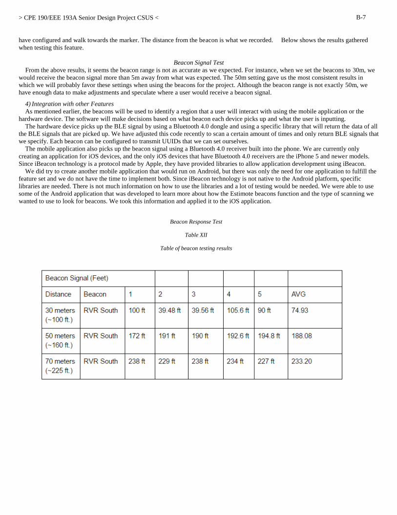
> CPE 190/EEE 193A Senior Design Project CSUS <
B-7
have configured and walk towards the marker. The distance from the beacon is what we recorded. Below shows the results gathered
when testing this feature.
Beacon Signal Test
From the above results, it seems the beacon range is not as accurate as we expected. For instance, when we set the beacons to 30m, we
would receive the beacon signal more than 5m away from what was expected. The 50m setting gave us the most consistent results in
which we will probably favor these settings when using the beacons for the project. Although the beacon range is not exactly 50m, we
have enough data to make adjustments and speculate where a user would receive a beacon signal.
4) Integration with other Features
As mentioned earlier, the beacons will be used to identify a region that a user will interact with using the mobile application or the
hardware device. The software will make decisions based on what beacon each device picks up and what the user is inputting. The hardware device picks up the BLE signal by using a Bluetooth 4.0 dongle and using a specific library that will return the data of all
the BLE signals that are picked up. We have adjusted this code recently to scan a certain amount of times and only return BLE signals that
we specify. Each beacon can be configured to transmit UUIDs that we can set ourselves. The mobile application also picks up the beacon signal using a Bluetooth 4.0 receiver built into the phone. We are currently only
creating an application for iOS devices, and the only iOS devices that have Bluetooth 4.0 receivers are the iPhone 5 and newer models.
Since iBeacon technology is a protocol made by Apple, they have provided libraries to allow application development using iBeacon. We did try to create another mobile application that would run on Android, but there was only the need for one application to fulfill the
feature set and we do not have the time to implement both. Since iBeacon technology is not native to the Android platform, specific
libraries are needed. There is not much information on how to use the libraries and a lot of testing would be needed. We were able to use
some of the Android application that was developed to learn more about how the Estimote beacons function and the type of scanning we
wanted to use to look for beacons. We took this information and applied it to the iOS application.
Beacon Response Test
Table XII
Table of beacon testing results
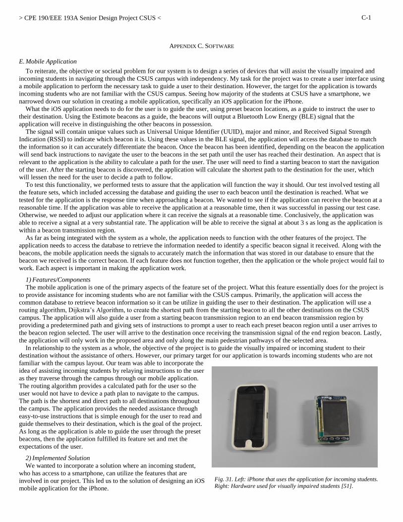
> CPE 190/EEE 193A Senior Design Project CSUS <
C-1
APPENDIX C. SOFTWARE
E. Mobile Application
To reiterate, the objective or societal problem for our system is to design a series of devices that will assist the visually impaired and
incoming students in navigating through the CSUS campus with independency. My task for the project was to create a user interface using
a mobile application to perform the necessary task to guide a user to their destination. However, the target for the application is towards
incoming students who are not familiar with the CSUS campus. Seeing how majority of the students at CSUS have a smartphone, we
narrowed down our solution in creating a mobile application, specifically an iOS application for the iPhone. What the iOS application needs to do for the user is to guide the user, using preset beacon locations, as a guide to instruct the user to
their destination. Using the Estimote beacons as a guide, the beacons will output a Bluetooth Low Energy (BLE) signal that the
application will receive in distinguishing the other beacons in possession. The signal will contain unique values such as Universal Unique Identifier (UUID), major and minor, and Received Signal Strength
Indication (RSSI) to indicate which beacon it is. Using these values in the BLE signal, the application will access the database to match
the information so it can accurately differentiate the beacon. Once the beacon has been identified, depending on the beacon the application
will send back instructions to navigate the user to the beacons in the set path until the user has reached their destination. An aspect that is
relevant to the application is the ability to calculate a path for the user. The user will need to find a starting beacon to start the navigation
of the user. After the starting beacon is discovered, the application will calculate the shortest path to the destination for the user, which
will lessen the need for the user to decide a path to follow.
To test this functionality, we performed tests to assure that the application will function the way it should. Our test involved testing all
the feature sets, which included accessing the database and guiding the user to each beacon until the destination is reached. What we
tested for the application is the response time when approaching a beacon. We wanted to see if the application can receive the beacon at a
reasonable time. If the application was able to receive the application at a reasonable time, then it was successful in passing our test case.
Otherwise, we needed to adjust our application where it can receive the signals at a reasonable time. Conclusively, the application was
able to receive a signal at a very substantial rate. The application will be able to receive the signal at about 3 s as long as the application is
within a beacon transmission region. As far as being integrated with the system as a whole, the application needs to function with the other features of the project. The
application needs to access the database to retrieve the information needed to identify a specific beacon signal it received. Along with the
beacons, the mobile application needs the signals to accurately match the information that was stored in our database to ensure that the
beacon we received is the correct beacon. If each feature does not function together, then the application or the whole project would fail to
work. Each aspect is important in making the application work.
1) Features/Components
The mobile application is one of the primary aspects of the feature set of the project. What this feature essentially does for the project is
to provide assistance for incoming students who are not familiar with the CSUS campus. Primarily, the application will access the
common database to retrieve beacon information so it can be utilize in guiding the user to their destination. The application will use a
routing algorithm, Dijkstra’s Algorithm, to create the shortest path from the starting beacon to all the other destinations on the CSUS
campus. The application will also guide a user from a starting beacon transmission region to an end beacon transmission region by
providing a predetermined path and giving sets of instructions to prompt a user to reach each preset beacon region until a user arrives to
the beacon region selected. The user will arrive to the destination once receiving the transmission signal of the end region beacon. Lastly,
the application will only work in the proposed area and only along the main pedestrian pathways of the selected area. In relationship to the system as a whole, the objective of the project is to guide the visually impaired or incoming student to their
destination without the assistance of others. However, our primary target for our application is towards incoming students who are not
familiar with the campus layout. Our team was able to incorporate the
idea of assisting incoming students by relaying instructions to the user
as they traverse through the campus through our mobile application.
The routing algorithm provides a calculated path for the user so the
user would not have to device a path plan to navigate to the campus.
The path is the shortest and direct path to all destinations throughout
the campus. The application provides the needed assistance through
easy-to-use instructions that is simple enough for the user to read and
guide themselves to their destination, which is the goal of the project.
As long as the application is able to guide the user through the preset
beacons, then the application fulfilled its feature set and met the
expectations of the user.
2) Implemented Solution
We wanted to incorporate a solution where an incoming student,
who has access to a smartphone, can utilize the features that are
involved in our project. This led us to the solution of designing an iOS
mobile application for the iPhone.
Fig. 31. Left: iPhone that uses the application for incoming students.
Right: Hardware used for visually impaired students [51].
> CPE 190/EEE 193A Senior Design Project CSUS <
C-2
Since our project utilizes iBeacon technology made by Apple, this was a simple solution to come by. Apple has developed APIs that
can work in parallel with iBeacon technology and iPhone. We are using Estimote beacons that outputs a BLE signal that has
distinguishing values that the iPhone can receive from the signal. The application will retrieve the UUID, major and minor, and RSSI
values. For our purposes for this project, we only need to use the minor value of the beacon signal to distinguish the difference between
other beacons. The beacons are covering a specific area of the CSUS campus and we only need the minor value to identify which beacon
the application received. The beacons are used to assist the user by relaying information to the application where the device will decode
the signal and send instruction sets to the user so he/she can use it to guide themselves through the campus. With this minor value, the
application will use that to match the minor value it received from the database and use that beacon information to give specific
instructions to reach that beacon. Overall, the application will access the database, use the minor value to find the beacon with matching
value, and relay the information back to the user so they can guide themselves to their destination.
3) Testing Results
After performing the needed testing for the mobile application, we achieved results that were helpful in improving our project. Through
various amounts of testing, our team was able to understand our project at a more technical level. We wanted to test our feature set and
reassure that our mobile application has met the requirements specified in our feature set “punch list”. The goal for testing the application
was to make sure that the application can fulfill its functionality as stated in the feature set “punch list” through our test methods to dictate
to us whether the application has passed or failed testing.
One of the most important tests that we performed on the application is the response time for the application. When we tested the
application response time this correlates to the other features of the application. By testing the application’s response time, we were able
to verify that it was able to access the database, receive transmission region signals from the beacons, and use the signal information to
guide the user to their destination. With this in mind, the goal of the test was to see how responsive the application is when receiving the
signal. As long as the mobile application can receive a beacon signal, it should be able to perform the other functionalities specified in the
feature set “punch list”. In respect to passing or failing, if the application responds to the signal at an appropriate time, then it would have
successfully passed the test. Otherwise, we will need to examine the problem and figure out why the application is slowly responsive to
the signal. To test the response time, we wanted to test the application when the beacon signal is at 30 m, 50 m, and 70 m. Below shows
the results of the response time of the mobile application.
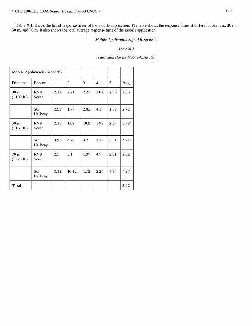
> CPE 190/EEE 193A Senior Design Project CSUS <
C-3
Table XIII shows the list of response times of the mobile application. The table shows the response times at different distances; 30 m,
50 m, and 70 m. It also shows the total average response time of the mobile application.
Mobile Application Signal Responses
Table XIII
Tested values for the Mobile Application
Mobile Application (Seconds)
Distance Beacon 1 2 3 4 5 Avg
30 m
(~100 ft.)
RVR
South
2.12 2.21 2.27 3.82 2.36 2.56
SC
Hallway
2.92 1.77 2.82 4.1 1.99 2.72
50 m
(~160 ft.)
RVR
South
2.15 1.02 10.9 1.92 2.67 3.73
SC
Hallway
3.98 4.79 4.2 3.23 5.01 4.24
70 m
(~225 ft.)
RVR
South
2.5 3.1 1.97 4.7 2.31 2.92
SC
Hallway
3.12 10.12 1.72 2.24 4.64 4.37
Total 3.42

> CPE 190/EEE 193A Senior Design Project CSUS <
C-4
Figure 32 shows the line graph representation of the response time of the mobile application at 30 m. The response time were taken at
samples with respect to time. In Figure 33, it shows a line graph similar to Figure 32, but with respect to 50 m.
Fig. 32. Line graph of Mobile Application for 30 m [53].
Fig. 33. Line graph of Mobile Application for 50 m [54].
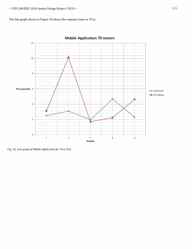
> CPE 190/EEE 193A Senior Design Project CSUS <
C-5
The line graph shown in Figure 34 shows the response times at 70 m.
Fig. 34. Line graph of Mobile Application for 70 m [55].

> CPE 190/EEE 193A Senior Design Project CSUS <
C-6
According to the test results, it is conclusive that the mobile application has a fast response time, which is beneficial when receiving
beacon signals as one walks through the CSUS campus. With the results gathered, it seems that the mobile application averages at a
response time of 3.42 s, which is relatively fast. At 50 m, our application had very consistent results of about 2 s or 4 s, which is the
consistency we wanted in our mobile application. What we noticed in our project is that sometimes our beacons would go to “sleep”.
Meaning, that our Estimote beacons goes to a powered down state where the signal is not being outputted from the beacon. This also
validates that the application was able to distinguish other beacons through the minor value it receives from the signal using the database
we created. With each beacon we had, the application was able to relay instructions to the user so that he/she can guide themselves to their
destination. As it can be seen, the mobile application has passed its testing plan and can be further improved upon until it is fully function
to be used by the user.
4) Integration with other features
When being integrated with the other features of the project, the mobile application functions along with the database and the beacons.
With respect to the database, the mobile application communicates with the database to receive information on a particular beacon.
Essentially, when a user approaches a beacon and receives a signal from it, the application will go to the database and will identify which
beacon the user has approached. Once the beacon was identified, the application will continue the rest of its functionality to guide the user
to their destination. In terms of the beacon, the application is using them as a guide for the user to direct themselves to the destination. The
application will receive the distinguishing information that the beacon signal outputs. With the information from the beacons, the
application will decode the information and use that to relay the proper instructions to the user depending on the beacon signal the
application has received. This functionality will occur for all beacons utilized in this project. Each beacon will have a specified
instructions set that application will be giving to the user as they guide themselves through the CSUS campus.

> CPE 190/EEE 193A Senior Design Project CSUS <
D-1
APPENDIX D. MECHANICAL DRAWINGS AND SUPPORT DOCUMENTATION
*There are not mechanical drawings and support documentation associated with this project.

> CPE 190/EEE 193A Senior Design Project CSUS <
E-1
APPENDIX E. VENDOR CONTACTS
Contacts: SSWD (Services to Students with Disabilities)
On behalf of Project Icarus from the College of Engineering and Computer Science we would like to express our appreciation to the
Services to Students with Disabilities (SSWD) for the input in helping us with our senior design project to help students with disabilities.
The department’s knowledge with working with disabled students assisted us in designing our project design. We would also like to
thank you for meeting with our group to help increase our awareness and understanding of how the CSUS visually impaired students get
around campus. If it wasn’t for the SSWD office we would not have been as successful as we were for this project. With their contribution
we hope to make an impact on the CSUS campus.
The generous support of individuals like you makes it possible for Senior Design Projects and other forms of organizations that require
funding to exist and to make California State University, Sacramento (CSUS) a great place to study and educate ourselves.
Contacts: UEI (University Enterprise Inc.)
On behalf of Project Icarus from the College of Engineering and Computer Science we would like to thank you for your
contribution of $700. Your financial support helps us continue in our mission and to assist those in our community. The generous support
of individuals like you makes it possible for Senior Design Projects and other forms of organizations that require funding to exist and to
make California State University, Sacramento (CSUS) a great place to study and educate ourselves.
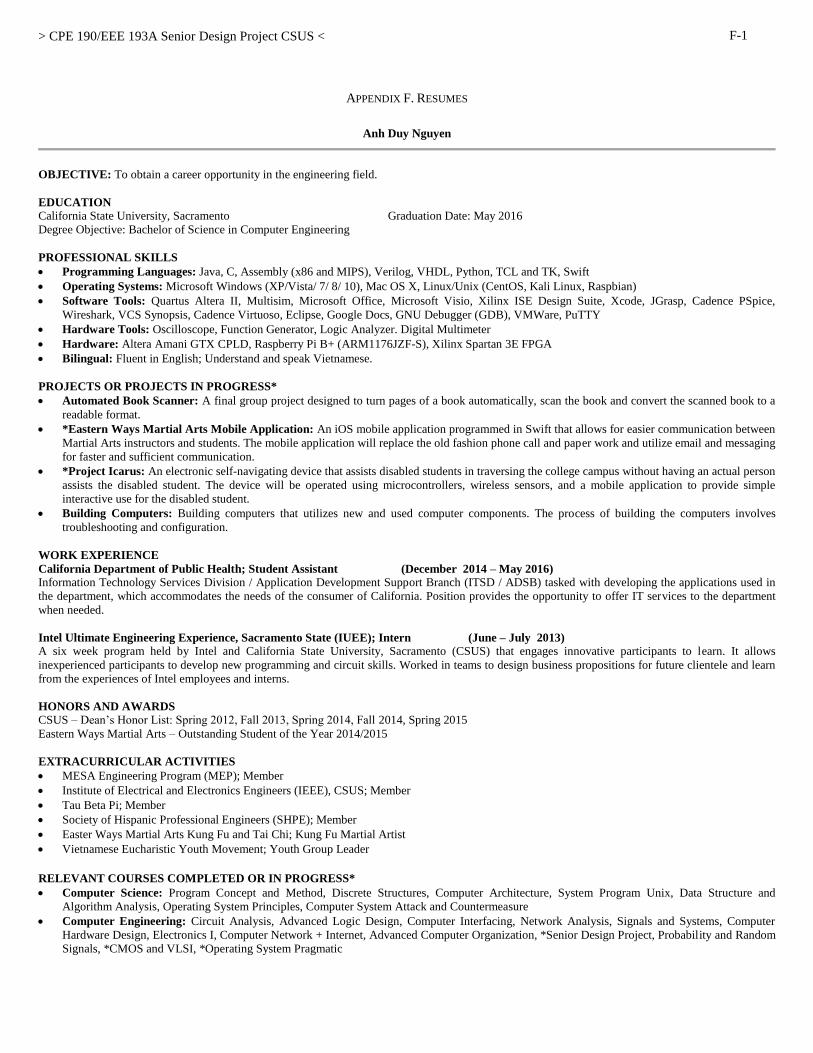
> CPE 190/EEE 193A Senior Design Project CSUS <
F-1
APPENDIX F. RESUMES
Anh Duy Nguyen
OBJECTIVE: To obtain a career opportunity in the engineering field.
EDUCATION
California State University, Sacramento Graduation Date: May 2016
Degree Objective: Bachelor of Science in Computer Engineering
PROFESSIONAL SKILLS
Programming Languages: Java, C, Assembly (x86 and MIPS), Verilog, VHDL, Python, TCL and TK, Swift
Operating Systems: Microsoft Windows (XP/Vista/ 7/ 8/ 10), Mac OS X, Linux/Unix (CentOS, Kali Linux, Raspbian)
Software Tools: Quartus Altera II, Multisim, Microsoft Office, Microsoft Visio, Xilinx ISE Design Suite, Xcode, JGrasp, Cadence PSpice,
Wireshark, VCS Synopsis, Cadence Virtuoso, Eclipse, Google Docs, GNU Debugger (GDB), VMWare, PuTTY
Hardware Tools: Oscilloscope, Function Generator, Logic Analyzer. Digital Multimeter
Hardware: Altera Amani GTX CPLD, Raspberry Pi B+ (ARM1176JZF-S), Xilinx Spartan 3E FPGA
Bilingual: Fluent in English; Understand and speak Vietnamese.
PROJECTS OR PROJECTS IN PROGRESS*
Automated Book Scanner: A final group project designed to turn pages of a book automatically, scan the book and convert the scanned book to a
readable format.
*Eastern Ways Martial Arts Mobile Application: An iOS mobile application programmed in Swift that allows for easier communication between
Martial Arts instructors and students. The mobile application will replace the old fashion phone call and paper work and utilize email and messaging
for faster and sufficient communication.
*Project Icarus: An electronic self-navigating device that assists disabled students in traversing the college campus without having an actual person
assists the disabled student. The device will be operated using microcontrollers, wireless sensors, and a mobile application to provide simple
interactive use for the disabled student.
Building Computers: Building computers that utilizes new and used computer components. The process of building the computers involves
troubleshooting and configuration.
WORK EXPERIENCE
California Department of Public Health; Student Assistant (December 2014 – May 2016)
Information Technology Services Division / Application Development Support Branch (ITSD / ADSB) tasked with developing the applications used in
the department, which accommodates the needs of the consumer of California. Position provides the opportunity to offer IT services to the department
when needed.
Intel Ultimate Engineering Experience, Sacramento State (IUEE); Intern (June – July 2013)
A six week program held by Intel and California State University, Sacramento (CSUS) that engages innovative participants to learn. It allows
inexperienced participants to develop new programming and circuit skills. Worked in teams to design business propositions for future clientele and learn
from the experiences of Intel employees and interns.
HONORS AND AWARDS
CSUS – Dean’s Honor List: Spring 2012, Fall 2013, Spring 2014, Fall 2014, Spring 2015
Eastern Ways Martial Arts – Outstanding Student of the Year 2014/2015
EXTRACURRICULAR ACTIVITIES
MESA Engineering Program (MEP); Member
Institute of Electrical and Electronics Engineers (IEEE), CSUS; Member
Tau Beta Pi; Member
Society of Hispanic Professional Engineers (SHPE); Member
Easter Ways Martial Arts Kung Fu and Tai Chi; Kung Fu Martial Artist
Vietnamese Eucharistic Youth Movement; Youth Group Leader
RELEVANT COURSES COMPLETED OR IN PROGRESS*
Computer Science: Program Concept and Method, Discrete Structures, Computer Architecture, System Program Unix, Data Structure and
Algorithm Analysis, Operating System Principles, Computer System Attack and Countermeasure
Computer Engineering: Circuit Analysis, Advanced Logic Design, Computer Interfacing, Network Analysis, Signals and Systems, Computer
Hardware Design, Electronics I, Computer Network + Internet, Advanced Computer Organization, *Senior Design Project, Probability and Random
Signals, *CMOS and VLSI, *Operating System Pragmatic

> CPE 190/EEE 193A Senior Design Project CSUS <
F-2
Rohit Pandit OBJECTIVE: A position in Computer Engineering.
EDUCATION: In progress: BS, Computer Engineering, CSU Sacramento; May 2016
RELATED COURSES: Operating System Pragmatic* Senior Design Project I Electronics I Unix System Management
Problem & Random Signal* Robotics Operating System Principles Network Analysis
Senior Design Project II* Computer Network + Internet Signals and Systems Advanced C++ Programming
Advanced Computer Organization Data Structures and Algorithm Dev. Advanced Logic Design Assembly Language
Computer Hardware Design CMOS and VLSI Computer Interfacing * In progress as of Spring 2016
KNOWLEDGE AND SKILLS Computer Languages: C/C++, Java, Verilog, VHDL, X86 Assembly, MIPS, Unix, Python, HTML/CSS, SQL, Latex
Hardware/Software: Skilled at troubleshooting and solving hardware and software problems. Able to learn and work with new
technologies easily. Skilled in setup, maintenance, documentation and training of hardware and software.
Computer Skills: MultiSim, VMWare, Pspice, Cadence18, Eclipse, Altera Quartus, Putty, FPGA, Synopsys, Matlab, SharePoint
Leadership/Management: Developed strong leadership skills while serving multiple officer positions for Competitive Robotics-
responsible for maintaining records and documentation; setting up events, procuring funds, materials, food, and space.
Coached recreational soccer teams in Sutter, CA from 2007 through 2009.
Languages: English; Intermediate language skills in Hindi, Punjabi, and Spanish
PROJECT EXPERIENCE: Senior Design: Project goal is to help students navigate the CSUS campus through a portable device. This portable device is
aimed for visually impaired and incoming students. Design will aim to reduce dependency for students that require individual
assistance.
Robotic Arm: Coded a robotic arm designed to scan and find Lincoln Logs on a given plane, pick up the logs in the middle, and
build a house in a prescribed location. The project required learning C++, running calculations on three-dimensional mid-
points, working with teams and delegating responsibilities, and improvising parts from other gadgets. The team of six
completed the project over the course of six months.
Datapath: With a 2 person team used a given set of instructions to build a datapath and wrote code-implementing solution as
quickly as possible. The project was broken into 2 phases: In phase one the team designed the datapath, and in phase two the
team coded each component of the datapath.
CMOS Design for Flash ADC & Dual-Slope ADC: Built a Flash ADC with a 2 person team. Learned Cadence software in
order to create the gate, layout, and schematic views.
TV Remote Controlled RC Car: Reverse engineered a radio controlled car with a team of 3. The project was designed to enable
the car via an original Comcast remote control.
Arena Mover Robot: Worked on the electrical, controls, sensors, and app to control a robot with a team of 5. This robot is
intended to help carry up to 800LBs for any and all CSUS clubs & affiliations.
DIY Microscope: Built a do-it-yourself microscope out of materials that were savaged around the house. This microscope is
intended for phones to view objects at a close range.
WORK EXPERIENCE:
Housing and Technology Services SA Housing and Residential Life, CSUS Feb 2014- Present
Responsible for trouble shooting hardware and software problems. Responsible for managing software network portals.
Entrusted with security and administration privileges. Set up a tracking system for completing tasks and keeping supervisors
informed.
Cashier & HW/SW Tech Sutter Mini Mart Jan 2007- Present
Intern – Housing and Technology Services Housing and Residential Life, CSUS May 2015-Aug 2015
Front Desk Student Assistant Housing and Residential Life, CSUS Nov 2013- Feb 2014
ACTIVITIES AND ACCOMPLISHMENTS: Chair for Engineering and Computer Science Exposition- Engineering Joint Council Present
Vice Chair- Hornet Pride Leadership Challenge Present
SpaceX-Hyperloop Pod Competition Present
Active Member of :MEP, SHPE, EOP, IEEE Present
Project Manager, Adviser, Event Coordinator, Treasurer, Secretary- Competitive Robotics Aug 2013-May 2015
Working 17 hours per week, while carrying 17 units, and being active in all the above organizations.

> CPE 190/EEE 193A Senior Design Project CSUS <
F-3
Nolram Ansay
OBJECTIVE: To gain experience relating to a career path in Computer Engineering.
EDUCATION:
CSU Sacramento B.S. Computer Engineering Graduation 05/2016
RELATED COURSES:Advanced Logic Design
Computer Interfacing
Systems Programming in Unix Programming Concepts & Methodology I & II
Operating System Principals
Computer Networks and Internets
Advanced Computer Organization
Computer Hardware Design
Network Analysis
Microcomputers & Assembly Lang.
Data Structure & Algorithm Analysis
Signals and Systems
Computer Software Engineering*
CMOS and VSLI*
Operating System Pragmatics*
*In Progress as of Spring 2016
HONORS: Tau Beta Pi Engineering Honor Society Member
Dean's Honor List
California Scholarship Federation
SKILLS:
Programming/Hardware Languages Java, Verilog, VHDL, C, x86 Assembly, UNIX Shell Scripting, Python
Hardware Xilinx XC3S500E FPGA, Amani GTX CPLD, Arduino Uno, Propeller Microcontroller, Raspberry Pi
Software Xilinx ISE, VMWare, Arduino, NI Multisim, PuTTY, Sony Vegas Pro, MiKTeX, jGRASP, MS Office
Tools Diligent Analog Discovery, Oscilloscope, Function Generator, Digital Multimeter, Logic Analyzer
Operating Systems Windows, Linux, Android
Strengths • Excellent at computer keyboarding and keypad typing
• Highly dependable at solving complex programming problems and analyzing computer logic
• Ability to learn new concepts quick and efficiently
• Can work in diverse teams and communicate well with others
• Strong organizational and time management skills (Full time student working part-time 4 days a week)
PROJECTS:
Project Icarus In the process of creating a network of devices that will allow those who are visually impaired or new to the CSUS school navigate campus
using either a mobile application or wearable hardware device. The project consists of a four-person team and utilizes iBeacon technology,
the Raspberry Pi, and both iOS and Android mobile applications. In charge of producing the Android mobile application that will allow
navigational aid for the students and managing the tests for the beacons.
FPGA Designs Created several project designs using a Spartan FPGA that include a binary multiplier which takes 2 four-digit binary number inputs and
displays results using LEDs, a traffic controller that utilizes state machines, and a module that controls a LCD screen. The projects applied
both Verilog and VHDL to accomplish various applications of hardware logic and electronic systems.
Book Scanner Built a project with members of a four-person team that consists of an Arduino and Raspberry Pi that turns a textbook's pages using servo
motors and takes a picture using a webcam. Provided the Raspberry Pi interaction with the Arduino using serial communication and created
user interface using an LCD screen and push buttons.
MIPS Processor Built a 16-bit MIPS processor that featured a five stage pipelined system that executes instructions such as load word, store word, rotate
left/right, and other common instruction. This system was designed from scratch and was implemented using Verilog and simulated on
Synopsys which demonstrated a basic MIPS processor.
Safe Rides Application Currently working on developing an application that will help the CSUS Safe Rides program. This will either be a web-based application or
mobile-based application. This is a group project for a computer software engineering class in which the focus is more on the software
development lifecycle rather than the implementation of the project.
WORK EXPERIENCE:
Manager/Team Lead
Cashier
Starbread Bakery, Sacramento, CA
Sizzler Restaurant, Sacramento, CA
08/14 – Present
05/14 – 08/14

> CPE 190/EEE 193A Senior Design Project CSUS <
F-4
Matthew Caesar Gorospe
OBJECTIVE: To obtain a challenging position in a high quality engineering environment where my resourceful experience and academic skills will add
value to organizational operations.
EDUCATION:
California State University, Sacramento
Degree Objective: Bachelor of Science in Electrical Engineering
Planned Graduation: Spring 2016
RELEVANT COURSES COMPLETED OR IN PROGRESS*:
Electrical Engineering Courses: Electronics I, Electronics II, Intro to Logic Design, Intro to Circuit Analysis, Applied Electromagnetics,
Electromagnetic Conversion, Advanced Logic Design, Introduction to Microprocessor, Network Analysis & LAb, Signals and Systems,
Computer Hardware Design, Electronics I, *Senior Design Project I and II, Modern Communication Systems, Digital and Wireless
Communications, Advanced Hardware Design, Probability and Random Signals, *CMOS and VLSI, *Physical Electronics
, Computation Methods and Application, Introduction to C Programming, *Digital Control Systems, Introduction to Feedback Systems
PROFESSIONAL SKILLS:
Programming languages: C, Verilog, VHDL, Python, Visual Basic
Operating Systems: Microsoft Windows (XP/Vista/ 7/ 8/ 10), Mac OSX, Linux/Unix
Software: Quartus, Multisim, Microsoft Office, Xilinx, LTspice, PSpice, Microsoft Visual Studio, Microsoft Visio, MATLAB, Cadence
Virtuoso, ADS (Advanced Design System)
Tools: Amani GTX CPLD, Oscilloscope, Diligent Analog Discovery, Arduino UNO, Spartan 3E FPGA, Raspberry Pi, Logic Analyzer, Intel
Edison
PROJECTS OR PROJECTS IN PROGRESS*:
Water temperature and level regulating system: Our team’s objective was to create a system that regulated water temperature and water
level by using microcontrollers and several other electrical components.
*Project Icarus: An electronic self-navigating device that assists disabled students in traversing the college campus without having an actual
person assists the disabled student. The device will be operated using microcontrollers, wireless sensors, and a mobile application to provide
simple interactive use for the disabled student.
Other class projects
o Antenna Patch
o Design Communication System through Simulink
o PLD project
o Research Paper on 3D Memory
o CPE 151
COMMUNICATION/ORGANIZATION:
Punctual, motivated, innovative, and reliable. Strong ability to quickly adjust and adapt to unexpected situations.
Remarkable communication skills through written reports and interactions with team members during lab and peers at the work place.
WORK EXPERIENCE:
Regal Cinemas Entertainment Group, October 11, 2010 – Still currently employed
Responsibilities include:
customer service
food preparation
ticket selling
auditorium cleaning
theatre checking
EXTRACURRICULAR ACTIVITIES
Institute of Electrical and Electronics Engineers (IEEE), CSUS; Member
Volunteer basketball coach at Natomas Charter Middle School 2009
Volunteer at Sacramento Public library 2009-2010
Top Related