


Languages
Pages
Legal


Copyright
by
Bharathwaj Sankaran
2014
The Thesis Committee for Bharathwaj Sankaran
Certifies that this is the approved version of the following thesis:
An investigation of factors impacting life-cycle application of Civil
Integrated Management (CIM)
APPROVED BY
SUPERVISING COMMITTEE:
William J. O’Brien
Fernanda L. Leite
Supervisor:

An investigation of factors impacting life-cycle application of Civil
Integrated Management (CIM)
by
Bharathwaj Sankaran, B.Tech
Thesis
Presented to the Faculty of the Graduate School of
The University of Texas at Austin
in Partial Fulfillment
of the Requirements
for the Degree of
Master of Science in Engineering
The University of Texas at Austin
December 2014

iv
Acknowledgements
I would like to express my sincere gratitude to Dr. William J. O’Brien for being
my advisor and it has been a privilege to work with him. I thank him for his valuable
insights and continuous support and motivation throughout this research. I would also
like to thank Dr. Fernanda Leite for reviewing my thesis and providing valuable inputs.
Special thanks to Joshua Johnson for his assistance in collecting the survey information
necessary for this work. I also wish to thank Cameron Schmeits, who has been extremely
helpful in providing timely assistance for resolving important issues related to this
research. My sincere thanks to Nabeel Khwaja for providing me this wonderful
opportunity to work with the Center for Transportation Research and helping me explore
this research area further.
Heartfelt thanks to my parents Mrs. and Mr. Sankaran, and my brother Prasanth
Sankaran who have been unwavering in their love and encouragement in helping me
realize the aspirations of my life. Finally, I would also like to express my deepest
appreciation to my best roommates – Mahesh Srinivasan and Vaidyanathan Sethuraman –
for their support and encouragement throughout my stay at Austin.
v
Abstract
An investigation of factors impacting life-cycle application of Civil
Integrated Management (CIM)
Bharathwaj Sankaran, M.S.E
The University of Texas at Austin, 2014
Supervisor: William J. O’Brien
Highway projects are delivered in a complex environment that involves
participation of diverse stakeholders with different objectives. Technological
advancements have provided better tools and techniques that if incorporated can lead to
effective project delivery complying with the multitude of objectives. Often the projects
are cost-driven, schedule-driven, or both. Presence of ongoing traffic poses an additional
challenge for the developers as it impacts the safety and comfort of both the commuters
and the construction workers. A wide variety of tools, techniques and work processes are
adopted across many projects depending on the project and agency requirements to make
the process of project management efficient across its life-cycle. Civil Integrated
Management (CIM) is a terminology that encompasses all such tools and technologies
that can facilitate the process of digital project delivery and asset management. This study
examines the current state of practice for CIM through surveys conducted at agency and
project level. The results of these surveys are summarized to provide an understanding of
the organizational and contractual issues related to CIM implementation and comprehend
the process of technologies implementation and associated performance benefits at the

vi
project-level. Significant factors impacting successful life-cycle CIM utilization are
elicited through the surveys and follow-up interviews and are investigated further under
four main categories – Technology Implementation Planning, Model-based workflow and
processes, design for construction automation and Information Management. Specific
examples have been provided for each of these factors to demonstrate their utility on
projects. The findings of this study will provide practitioners a list of key issues to be
considered for profitable and effective implementation of the CIM technologies across a
project’s life-cycle.
Keywords: Civil Integrated Management (CIM), digital project delivery and asset
management, technology Implementation Planning, model-based workflow. highway
projects

vii
Table of Contents
List of Tables ......................................................................................................... ix
List of Figures ..........................................................................................................x
Chapter 1 Introduction ...................................................................................1
Readers guide ..................................................................................................2
Chapter 2 Review of CIM technologies ........................................................4
3D/4D Modeling .............................................................................................5
Modern Surveying methods ............................................................................8
LiDAR....................................................................................................8
Aerial survey ........................................................................................10
Intelligent compaction ..................................................................................11
Automated Machine Guidance .....................................................................12
Utility engineering ........................................................................................13
Alternative contracting method and legal issues ..........................................15
Chapter 3 A review of CIM workflows .......................................................18
CIM workflows – state of practice at DOTs .................................................19
Research objective ........................................................................................23
Chapter 4 Research Methodology ...............................................................25
1. Objective and structure of the survey ..................................................25
2. Summary of survey results...................................................................27
Agency surveys ....................................................................................28
Project Surveys ....................................................................................29
Chapter 5 Analysis of life-cycle factors ......................................................31
1. Technology Implementation Planning .................................................31
Organization-level Planning ................................................................32
Project-level planning ..........................................................................34
2. Model-based workflow and processes .................................................38

viii
Factors impacting Level of Detail (LOD) ............................................40
LOD specifications development .........................................................43
Case studies for validation of LOD .....................................................46
Utilizing LOD recommendations in practice .......................................49
3. Designing for construction automation ................................................50
4. Data exchange tools and information management .............................54
Information Modeling and Geospatial data collaboration ...................56
Chapter 6 Discussion and Conclusion .........................................................58
Recommendation for future work .................................................................59
Appendices:............................................................................................................61
References ..............................................................................................................63

ix
List of Tables
Table 4-1 Topic-wise summary of questions in the agency and the project surveys27
Table 5-1A synopsis of requirements for CIM Technology Implementation Planning
...........................................................................................................35
Table 5-2 An example Technology-Function-Process Matrix for project life-cycle37
Table 5-3 Factors impacting LOD for modeling highway projects .......................40
Table 5-4 Guidelines for ascertaining LOD...........................................................43
Table 5-5 Guidance table for choosing the degree of information ........................45
Table 5-6 A representative modeling matrix for highway projects .......................50
Figure 5.5 Automation usability in highway projects ............................................51
Table 5-7 Existing standards to promote software interoperability and data exchange
...........................................................................................................55
Table A 1 A synopsis of CIM technologies classified by Project phases ..............61
Table A 2 A compilation of benefits and challenges of CIM technologies ...........62

x
List of Figures
Figure 2.1 Thematic representation of CIM (Adapted from FHWA, 2012a) ..........4
Figure 2.2 Rendered image of the proposed model of Mitchell Interchange (Parve,
2012) ...................................................................................................6
Figure 2.3 4D model for schedule phasing in Mitchell Interchange project (Parve,
2012) ...................................................................................................7
Figure 2.4 Comparison between different LiDAR technologies (Siebern, 2012) .10
Figure 2.5 Intelligent Compaction workflow (FHWA, 2013c) .............................12
Figure 2.6 Proposed 3D model with existing 3D model of utilities (Oldenburg, 2011)
...........................................................................................................14
Figure 3.1 CIM workflow for transportation projects (Parve, 2014) .....................19
Figure 3.2 Workflow - design and construction stage (Parve, 2012) ....................20
Figure 3.3 Proposed workflow of highway projects for CIM (Adapted from Singh,
2013) .................................................................................................22
Figure 4.1 Proposed Research approach ................................................................30
Figure 5.1 Organizational Productivity at CIM implementation (Autodesk, 2007)33
Figure 5.2 Pictorial representation of a 3-D DTM Surface model (Category 0) ...46
Figure 5.3 3D model showing lane closures and construction activities (Category 1)
...........................................................................................................47
Figure 5.4 (Left) Perspective of the 3-D model of the PGBT project, (Right) Utilities
modeled for clash detection process (Category ―2‖) ........................48

1
Chapter 1 Introduction
―Civil Integrated Management (CIM) is a term that recently has come to be
applied to a wide range of practices and tools entailing collection, organization, and
management of information in digital formats about a transportation infrastructure
project‖ (FHWA, 2012a, p.1). It encompasses the technologies and methods that facilitate
the transition from traditional ways of project delivery and facility management (e.g., 2D
drawings, specifications) to a more sophisticated digital project delivery and asset
management (e.g., modern surveying methods, model-based design, integrated design
and construction process and digital databases for asset management) (FHWA, 2012a).
The construction sector, all across the world, has recognized the need for undergoing a
paradigm shift to applying ways and technologies that can make digital project delivery a
reality for infrastructure projects. Moreover, the amount of data and information
generated during each phase has become so huge that it has become difficult to track and
manage with traditional methods of information and data sharing (O’Brien et al, 2012).
Designated as an initiative of Every Day Counts – 2 (EDC-2) program by FHWA,
CIM is primarily intended to focus on promoting successful and effective life-cycle
application of modern technologies such as advanced surveying methods, n-D model-
based design and construction, subsurface mapping of utilities, electronic document
approval, and increased use of precast and modular elements for construction. In
addition, it suggests evaluating alternative contracting methods (e.g., D-B, CM/GC,
Franchise contracting) and Alternative Technical Concepts (ATC) as they create a default
environment for team collaboration and integration of design and construction phases.
Also from a legal standpoint, it recommends having appropriate dispute resolution

2
clauses in place to solve potential issues that may arise due to the implementation of
digital approach for project delivery (FHWA, 2012).
Many owner agencies and project companies across the world have deployed
various technologies depending on their resource availability and project requirements.
However, no single project has reported to have implemented the full spectrum of CIM
technologies across its life-cycle. Yet, a structured survey of agencies practices and
projects that have demonstrated the values offered by deploying CIM tools on their work
processes, can help understand the level of utilization of information modeling and other
technological tools and investigate the factors contributing to successful life-cycle
implementation.
READERS GUIDE
This thesis is organized into five chapters. Chapter 2 provides an overview of
current elements and definitions of CIM as reported by FHWA and other state
transportation agencies. This includes description of various technologies used on
projects and agency-related tools that can assist in electronic data management across
project life-cycle. Legal and governance problems and available guidance for the usage
of digital intellectual property on transportation projects are also presented. Chapter 3
explores the existing literature on CIM workflows. Since CIM includes a wide variety of
emerging technologies, challenges with the existing specifications and guidance are
discussed. Emphasis is laid on understanding the impacted project work processes due to
technology implementation. It ends with problem statement of this study. Chapter 4
begins with reasoning the research methodology adopted to answer the problem
statement. It describes the data collection process and enumerates the pertinent data
sources. It illustrates the strategy adopted to structure the questionnaire for the two
3
surveys designed to investigate CIM implementation at agency and project level. It
discusses in brief the results and inferences from the surveys. A few follow-up interviews
were also conducted for the projects identified through surveys based on their success
with implementing various CIM tools at different phases. Critical factors concerning life-
cycle utilization of various technologies are then deduced for detailed investigation.
Chapter 5 discusses in detail the identified factors that can assist in life-cycle CIM
implementation. They are analyzed under four categories – Technology Implementation
Planning, Model-based workflow and processes, designing for construction automation,
and data management. Finally, Chapter 6 outlines the conclusions from the research and
provides recommendations for future research in the topic.

4
Chapter 2 Review of CIM technologies
In practice, CIM is a set of technologies and processes that improves
predictability of the project performance and lead to better outcomes at different stages of
the construction life-cycle - from conceptual planning, design and engineering,
procurement and construction, commissioning and operations and maintenance. There
exists a wide range of technologies and tools that can assist in achieving this objective
and many Departments of Transportation (DOTs) have been utilizing them during
depending on the requirements and constraints. A list of all the constituents of CIM are
identified from the literature and agencies’ publications and is presented in Figure 2-1
Figure 2.1 Thematic representation of CIM (Adapted from FHWA, 2012a)
Technological
n-D modeling
Modern Surveying methods
Intelligent Compaction
Automated Machine Guidance
Utility Engineerng
Digital Asset Management
Contractual
Alternative Project Delivery Methods (D-B, CM/GC)
Alternative Technical Concepts (Lane Rentals, Warranty Clauses)
Managerial
Information Management
Project Management
Quality Management
Policies and governance
Legal Issues surrounding application of model-based project delivery and digital
asset management
Building blocks of CIM
5
The constituents of CIM are briefly discussed next to provide a synthesis of the current
state of practices related to the respective tool.
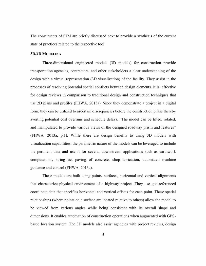
3D/4D MODELING
Three-dimensional engineered models (3D models) for construction provide
transportation agencies, contractors, and other stakeholders a clear understanding of the
design with a virtual representation (3D visualization) of the facility. They assist in the
processes of resolving potential spatial conflicts between design elements. It is effective
for design reviews in comparison to traditional design and construction techniques that
use 2D plans and profiles (FHWA, 2013a). Since they demonstrate a project in a digital
form, they can be utilized to ascertain discrepancies before the construction phase thereby
averting potential cost overruns and schedule delays. ―The model can be tilted, rotated,
and manipulated to provide various views of the designed roadway prism and features‖
(FHWA, 2013a, p.1). While there are design benefits to using 3D models with
visualization capabilities, the parametric nature of the models can be leveraged to include
the pertinent data and use it for several downstream applications such as earthwork
computations, string-less paving of concrete, shop-fabrication, automated machine
guidance and control (FHWA, 2013a).
These models are built using points, surfaces, horizontal and vertical alignments
that characterize physical environment of a highway project. They use geo-referenced
coordinate data that specifies horizontal and vertical offsets for each point. These spatial
relationships (where points on a surface are located relative to others) allow the model to
be viewed from various angles while being consistent with its overall shape and
dimensions. It enables automation of construction operations when augmented with GPS-
based location system. The 3D models also assist agencies with project reviews, design

6
reviews, and environmental compliance. According to FHWA (2013a, p.4), ―Models
provided pre-bid in a performance specification will allow contractor innovation and
reduce costs through application of data for machine guidance‖. Data from initial control
survey and Light Detection and Ranging (LiDAR) can also be incorporated into the
model to better model the existing conditions. Figure 2.2 shows a rendered image of the
3D model of Wisconsin DOT’s Mitchell Interchange project
Figure 2.2 Rendered image of the proposed model of Mitchell Interchange (Parve, 2012)
The incorporation of 4th
dimension to the model (schedule) allows the project
stakeholders to visualize the entire construction activities and their sequencing
virtually. Integrating project management processes with 4-D model enhances the clarity
in communication process and helps in better understanding of the design and

7
construction intent (CIC, 2010). O’Brien et al. (2012), Liapi (2003), Hartmann et al.
(2008) and several other researchers have validated with case studies the value offered by
3D and 4D computer-aided design (CAD) models for transportation projects towards
communication, technical design checking, construction planning, and work area
management. When modeled with a high level of detail, it can assist in identifying spatial
or temporal conflicts between different elements. Figure 2.3 demonstrates the usage of
4D construction phasing and scheduling on Wisconsin DOT’s Mitchell interchange
project.
Figure 2.3 4D model for schedule phasing in Mitchell Interchange project (Parve, 2012)

8
MODERN SURVEYING METHODS
Ever since the advent of sensing technologies, revolutionary changes have taken
place in surveying techniques and they have proved to be a major contributor to the
digital project delivery process. The modern surveying methods produce performance
improvements in many aspects (coverage, speed, cost, and data accuracy). Singh (2008)
categorizes modern surveying methods into two different types depending on their
mobility, coverage and type of usage.
Passive systems that include aerial photography and satellite imagery (aerial
survey).
Active systems include airborne LiDAR, and ground based stationary or mobile
3D laser scanning.
While the list can still be extended to include more, the most prominent methods are
discussed here. A complete list of surveying techniques is listed in the appendices (Table
A1).
LiDAR
LiDAR illuminates the target with a laser and performs distance calculations by
evaluating the time taken for the light to be reflected. It is used for scanning and
measurement in three different configurations: airborne, mobile and terrestrial. Airborne
LiDAR (Airborne laser scanning or ALS) involves mounting the equipment on a fixed-
wing aircraft or on a rotary-wing helicopter. For mobile LiDAR (mobile laser scanning, or
MLS), the scanning hardware is mounted on a moving ground vehicle. Terrestrial LiDAR
(Terrestrial laser scanning or static LiDAR) uses a ground scanning unit (Ellsworth,
2012).
A research conducted for Wisconsin DOT broadly summarized the application of
the three different types of LiDAR in the areas of surveying, highway design, corridor

9
development, incident management and critical infrastructure protection, traffic flow,
highway safety, rock cuts and geology (CTC & Associates LLC, 2010). Utah DOT has
leveraged the application of LiDAR for asset management (Ellsworth, 2012).
Static LiDAR scans the object’s geometry and facilitates solid object modeling. It
is generally used in mapping, reverse engineering structural analysis and testing and
performing as-built surveys of facilities (Singh, 2008). They are highly accurate, agile,
and cost effective and provide better resolutions on targets. Advancements in scanning
speed, accuracy and lowering of prices have made Mobile LiDAR a reliable and rapid
medium of data collection (Williams et al., 2013). Airborne LiDARs have very wide
coverage and commonly used in applications such as topography mapping, utility
transmission corridors, coastal erosion, flood risk mapping and watershed analysis.
However their accuracy is low and they are expensive. Figure 2.4 presents an objective
comparison between different categories of LiDAR based on their applications and key
characteristics. The point clouds collected through LiDAR can be used for extraction of
features through several post-processing tasks (Williams et al., 2013). This technology
also has the potential to be utilized throughout the entire project life-cycle. Williams
(2013) performed a holistic review of the current practices in LiDAR technologies and
documented application throughout various phases of a project from planning to asset
management.

10
Aerial survey
Aerial Surveys for transportation projects refers to the process of utilizing aerial
photography and other imagery for performing various engineering tasks. The processing
of such photographs for obtaining dimensional data for mapping, cadastral, design and
computation of earthwork and other construction quantities is achieved through
photogrammetry. FHWA (2011) classifies the procedure of aerial surveying into the
following important stages: Planning, reconnaissance survey of the area, reconnaissance
Figure 2.4 Comparison between different LiDAR technologies (Siebern, 2012)

11
survey of the route alternatives, preliminary survey of the selected route corridor, location
survey, survey during construction, and survey for collecting maintenance data.
Required Information can be obtained from available orthoimagery, that are being
collected by several governmental or private agencies (such as USGS National maps,
Google maps, Microsoft virtual earth, North Carolina DOT photogrammetry unit, Texas
Natural Resources Information System, Maine office of GIS and so on.).
INTELLIGENT COMPACTION
Compaction is one of the major operations among the pavement construction
processes that directly affect its long term performance. Intelligent Compaction (IC)
refers to the compaction of layers of pavements, such as ― soils, aggregate bases, or
asphalt pavement materials, using advanced vibratory rollers equipped with an integrated
measurement system, an onboard computer reporting system, accelerometers, GPS based
mapping, and optional feedback control‖ (FHWA, 2013c). The workflow associated with
a typical IC unit is showcased in Figure 2-5. The monitoring and control systems produce
unique color-coded images that facilitate identification of the equipment location, number
of passes and quality measurements. It is necessary in order to attain high quality and
uniformity of pavement materials, which in turn ensure long-term performance (FHWA,
2013c). The benefits are numerous in terms of optimized labor deployment and
construction time, reduced material variability, reduced compaction and maintenance
requirements, real-time monitoring of the process and control (Chang, 2011). Anderegg
& Kaufmann (2004) have experimented with IC and demonstrated that these dynamic
compactors, that create non-linear vibrations providing basis for continuous feedback
control systems, lead to reduced construction costs and greater reliability in the process.
Field investigations performed by Minnesota DOT have looked at the practical

12
considerations for Quality Assurance/ Quality Control (QA/QC) purposes while
integrating IC technologies with earthwork construction practices. Commonly reported
implementation challenges include relatively high equipment cost, high roller operating
skills and increased frequency of calibration and maintenance works.
Figure 2.5 Intelligent Compaction workflow (FHWA, 2013c)
AUTOMATED MACHINE GUIDANCE
Automated Machine Guidance (AMG) is often described as a downstream
application that takes information from 3D engineered models and augments them with
GPS-based location referencing for guiding the equipment during various paving
operations (FHWA 2013 b). It provides horizontal and vertical guidance in real time to
construction equipment operators. All the machines related to construction operations can
be equipped with this technology for performing grading or paving tasks in the field.
―The technology can increase productivity by up to 50 percent on some operations and
cut survey costs by as much as 75 percent‖ (FHWA, 2013b, p.1). Often cited advantages
of this technology as reported by FHWA (2013) include reduced construction costs,

13
reduced schedules, eco-friendly system (due to less fuel spent), increased quality of work
and increased safety.
However, this technology is not suitable for every project. A project should
possess major earthwork or paving operations, new alignments, a good Global
Navigation Satellite System (GNSS), and a 3-D Digital Terrain Model (DTM) surface for
to successfully utilize AMG (Caltrans 2009). Moreover other conditions such as lack of
training and lack of equipment for DOT construction management staff to perform
QA/QC checks also limit the use of AMG (FHWA, 2013b).
UTILITY ENGINEERING
Another major requirement of CIM as outlined by FHWA (2012) is mapping and
storing the utility data at appropriate quality levels in 3D (using technology such as RFID
subsurface mapping and Ground Penetration Radar, GPR), managing the risk associated
with the utility relocation design and coordination, and communication of utility data to
the concerned parties and stakeholders in transportation projects.
Given the complexity of this issue and widespread understanding and consensus
over its significance to success of any transportation project, FHWA and state DOTs have
been actively partnering and developing standards and guidelines to address this issue.
The American Society of Civil Engineers' (ASCE) Standard Guideline for the Collection
and Depiction of Existing Subsurface Utility Data was published and distributed in 2003.
Availability of 3D design models and utility information can help in resolving utility
conflicts during the pre-construction stage and avert schedule delays and cost overruns
(O’Brien et al. 2012). Figure 2.6 shows the 3D model of the proposed project along with
existing utilities in a Wisconsin DOT project.

14
Figure 2.6 Proposed 3D model with existing 3D model of utilities (Oldenburg, 2011)
In recent years, technologies such as RFID systems and GPR have become
popular. RFID technology makes use of electronic locators to tag and locate the utilities
and provide related information about the asset with reasonable level of accuracy. When
used in conjunction with system data maps, it can assist identifying ownership of any
particular utility among a group of assets (Norby, 2013).Another technology more
commonly being used for utility mapping is GPR. GPR uses high frequency
electromagnetic waves to locate the subsurface utilities. It utilizes differences in the
dielectric and conductivity properties of various components of the subsurface stratum to
evaluate the location of utilities (Jeong et al., 2003). Other technologies used to locate
utilities include Electromagnetic Imaging (EMI), Pipe and cable locators, and Three-
dimensional Radar tomography. Consistent with the objective of maintaining the utility
information in an efficient manner, Utility Conflict Matrix (UCM) is being implemented

15
across the country with different DOTs proposing their own structure of data storage
(Quiroga et al., 2012).
ALTERNATIVE CONTRACTING METHOD AND LEGAL ISSUES
Alternative contracting, in general, refers to the project delivery methods that can
assist in delivering projects in a more collaborative manner with the objective of making
the facility available to public faster while maintaining quality and cost-effectiveness.
FHWA (2012a) states that the following alternative methods are available for
consideration: Construction Manager / General Contractor (CM/GC), Design-Build (D-
B), Alternative Technical Concepts (ATC), Lane Rentals, and Warranty Clauses.
In the CM/GC contract, the process is broken down into two contracting phases.
In the first phase (also called design phase), the hired contractor works as a
consultant with designer and owner to identify risks, prepare cost estimates and
schedules. After completion of first phase, the contractor negotiates the price of
contract with the owner and upon reaching agreement the second phase
(construction phase) begins (FHWA, 2014a)
In the D-B contract, the owner identifies its needs and accepts proposals and
selects one D-B team for the entire project based on a best-value basis, to assume
the risk and responsibility for the design and construction of the facility (FHWA,
2014b).
The ATC process is commonly used with D-B delivery type, wherein the state
DOTs issue a Request for Proposals (RFP) with basic project configurations and
D-B teams submit ATCs based on their industry expertise. The DOTs review the
submissions and grant approval if the concept is acceptable. The D-B team can
then adopt this ATC in their technical and price proposal (FHWA, 2012b).

16
The Lane Rental technique tends to minimize the impact of a project on the
traveling public. A variant of cost-plus-time bidding, the allowable number of
days of closures and lane rental fees are determined during bidding stage of the
project and added to the standard bid to decide award of the contract. The
contractor will pay applicable lane rental fees (also called ―Lane Rental –
additional‖) if the allowable lane closures exceeds the contractually set duration.
Incentives may also be included in the stipulated contract price to encourage and
reward early completion. (Washington Department of Transportation, 2014)
Warranty clauses specify the desired performance characteristics of the elements
of a project over the stipulated warranty period and assign the responsibility for
repair or deficiencies. In Pavement Performance Contracts (PPC) and Design-
Build-Finance-Operate (DBFO) contracts, this period extends up to 35 years in
general. Projects with performance warranty clauses have proven to show
improved performance (FHWA, 2014c)
Although the alternative contracting methods have become more common,
executing projects through these strategies is not common across states and the approach
has not been uniform. Some states have done a few ―demonstration projects‖ and, as
such, have not yet decided to authorize widespread use. Other states have embraced these
methods and enacted legislatures (AIA, 2008).
The legal issues surrounding the ownership and maintenance of information
models have also not been clearly understood as there were no set guidelines (DeVries,
2012). Stakeholders need more clarity on liability of plan and survey data and how to
address the long-term liability of as-builts. Similar issues are also quite common in
building industry for which stakeholders utilize guidelines such as the standards laid out
by AIA regarding the legal issues surrounding BIM. National Cooperative Highway

17
Research Program’s (NCHRP) Legal Research Digest 58 team looked at the legal issues
surrounding the use of digital intellectual property in transportation projects. They
developed implementation guidelines to address the following issues: ownership issues of
an information model, applicability of copyright laws, protection of models and
collaborators, usage of disclaimers and Read-Only files, digital signatures,
interoperability issues, trade secrecy of technology used, and disclosure of model under
public information laws (Thomas, 2013).

18
Chapter 3 A review of CIM workflows
The literature review (Chapter 2) presented an insightful overview of the essential
building blocks of CIM with focus on various technologies, contract methods and legal
issues. The myriad of technologies, tools and management practices that is deployed on a
particular project depends on several factors such as resources availability, project
objectives and organizational constraints (O’Connor & Yang, 2004). There exist many
resources dealing with specifications, benefits and challenges of individual technologies
and processes tools. Moreover, many organizations had used these general guidelines and
developed their own specifications to suit their project characteristics (Ex: Washington
DOT’s Electronic Engineered Data guidelines).
CIM has been proposed as an agency-level initiative that can make the project
management process effective across the entire life-cycle. Moreover, FHWA has further
described CIM as the set of processes and objectives that leads to effective organization
and managed accessibility of data and information concerning the highway facility and
hence the focus should be beyond the successful promotion and application of
technologies (Ralls, 2013). Empirical evidence also suggests that technologies
application, by itself, doesn’t guarantee a direct positive impact on project performance
measures. It is the better integration of these technologies with the project work processes
and implementing the associated best practices that leads to good outcomes (Kang et al.,
2013). Thus, it is imperative to evaluate the process flow of these technologies on
projects.
Many of the lessons learned concerning CIM workflows and best practices are
being dispersed verbally or through concise presentations at relevant forums (such as
conferences). Recommendations concerning work flows and best practices for CIM (real
19
or ideal) were identified from the literature and state DOTs’ documents and are presented
next in this chapter
CIM WORKFLOWS – STATE OF PRACTICE AT DOTS
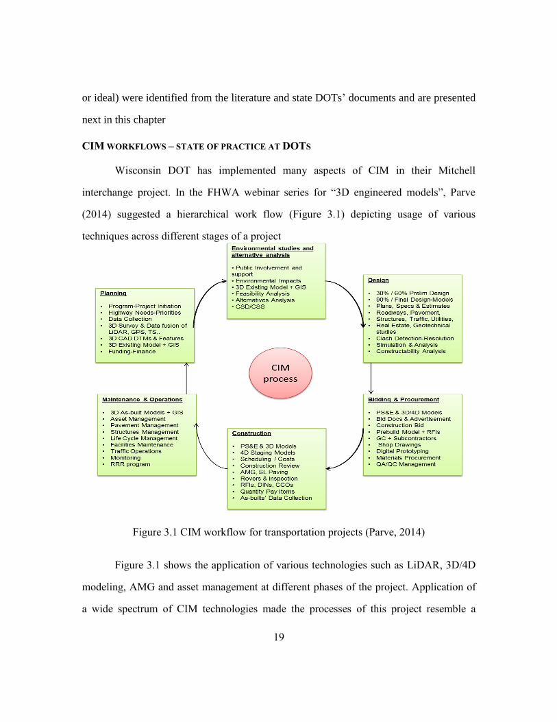
Wisconsin DOT has implemented many aspects of CIM in their Mitchell
interchange project. In the FHWA webinar series for ―3D engineered models‖, Parve
(2014) suggested a hierarchical work flow (Figure 3.1) depicting usage of various
techniques across different stages of a project
Figure 3.1 CIM workflow for transportation projects (Parve, 2014)
Figure 3.1 shows the application of various technologies such as LiDAR, 3D/4D
modeling, AMG and asset management at different phases of the project. Application of
a wide spectrum of CIM technologies made the processes of this project resemble a

20
typical digital workflow. Protocols and regulations were established during the early
stage of the project regarding the tools and processes to be followed throughout its life-
cycle. Technologies were chosen based on systematic assessment of project objectives,
scope, schedule, budget and team knowledge and experience. During the planning stage,
LiDAR technology was utilized for data collection. Control survey was performed to
establish high accuracy horizontal and vertical targets. The collected information was
then adjusted, classified and mapped to retrieve necessary features. Several information
modeling and visualization tools were also utilized in the design phase. The project
reported cost savings & cost avoidance in the form of reduced Requests for Information
(RFIs) and Design Issue Notices (DINs). An overview of workflow during design and
construction stage is shown in Figure 3.2.
Figure 3.2 Workflow - design and construction stage (Parve, 2012)

21
Figure 3.2 also shows different software and data exchange tools used in the
project. This system recommends collection of three major sources of data for the project
development – Roadways and structures, Utilities information and surface data. Advance
technologies such as digital photogrammetry, LiDAR surveys and field-checked Digital
Terrain Models (DTMs) were used for the data collection. The existing infrastructure and
proposed models were then modeled in 3D using different software tools (Autodesk Civil
3D, Revit, Microstation). LandXML was adopted as default data exchange format to
ensure software interoperability. 4D simulation and clash analysis were performed to
resolve spatial and temporal conflicts, leading to improved project performance in key
metrics. Eventually, this process ensured collaboration of stakeholders across multiple
disciplines and provided for design-construction coordination throughout the project.
Singh (2013) of Oregon DOT proposed a workflow encompassing key concepts
and components that will essentially form the major requirements of digital project
delivery in the future. It represents a pro-active data-centric approach and it may be used
to describe the data flow in the life-cycle management of highway projects. Driven by
technological advancements and an increased participation of agencies for digital
delivery of projects, the project development process may utilize most of the digitally
signed and archived asset data for surveying and engineering. This paradigm shift will be
facilitated and taken forward to 3D design based on virtual site and assist in construction
phase with machine automation and control processes. As-built surveys will be digitally
signed and stored in an asset management database, which will be maintained and
updated throughout its life-cycle. A pictorial representation of this workflow and
information exchange loop is shown in Figure 3.3.

22
Figure 3.3 Proposed workflow of highway projects for CIM (Adapted from Singh, 2013)
Guo et al., (2014) as part of their effort for NCHRP 20-68A, Scan 13-02 Advances
in Civil Integrated Management has evaluated the level of CIM adoption in Iowa and
Missouri DOTs based on the perceived usage levels of techniques such as 3D design and
LiDAR. Information was also captured regarding organizational structure and workflow
adoptions, development of specifications and guidelines and legal issues.
Anticipated to transition to a paperless construction delivery process by 2015,
Michigan DOT is at the forefront in implementing many of the CIM technologies related
to data management. Accordingly, the ―e-construction‖ initiative is purported to leverage
the potential of innovative technologies including the state-of-the-art surveying
techniques, n-D modeling based design and construction, partnering efforts, data storage
and archival, and use of secure and digitally encrypted electronic signatures. This pilot
effort is expected to benefits all stakeholders involved in the project delivery process
including design consultants, construction consultants, contractors, local agencies,
auditors and suppliers (Farr, 2013).

23
Analysis of issues pertaining to life-cycle utilization has been examined under
different contexts for BIM. Azhar (2011) acquired detailed cost data from ten projects to
perform a project level Return-On-Investment (ROI) analysis. The savings due to
adoption of information modeling were measured using “real” construction phase
“direct” collision detection cost avoidance and in some projects, notional savings were
computed using “planning” or “value analysis”. Examples of the significant issues to be
considered while integrating BIM with project execution processes are also available in
the literature (Eastman et al., 2008, Leite et al., 2011, Hartmann et al., 2012, Barlish &
Sullivan, 2012, Porwal & Hewage, 2013).
RESEARCH OBJECTIVE
The concepts and discussions presented thus far have covered the technologies,
and other building blocks of CIM. Practitioners and researchers are investigating the wide
spectrum of issues regarding any particular constituent of CIM. Since CIM is a recent
initiative and it also consists of some emerging practices specific to the requirements of
transportation projects, the common issues relevant to the system of CIM technologies
have not been investigated in detail. It will be beneficial to explore these issues that affect
life-cycle implementation of CIM for several project work processes at a system level.
This hypothesis gains significance if we consider technologies (such as 3-D modeling)
that can influence a variety of project tasks during various phases of a project.
Therefore, the objective of this research is to examine the deployment of CIM
technologies and understand the current state of practices at DOTs. Additionally, it is also
intended to elicit some of the major factors concerning life-cycle utilization of CIM and
study in detail their impacts on digital project delivery process. The focus is primarily on
the factors supporting implementation of the system of tools across a project rather than

24
any particular technology. It is anticipated that the lessons learned from analyzing these
factors would complement the knowledge in the existing literature and practical
execution guidelines for implementing CIM on projects.

25
Chapter 4 Research Methodology
As discussed in the Chapter 3, State transportation agencies and other project
stakeholders typically possess guidelines or have undertaken initiatives to formulate
guidelines for disparate building blocks of CIM. Some of the DOTs are in the transition
phase to incorporating the CIM technologies in their organization and projects. Since
CIM includes a wide variety of tools that also entail emerging technologies and practices,
no project or agency have systematically implemented CIM at its entirety. Practitioners
and researchers have been investigating issues concerning technologies on a case basis
but resources evaluating concurrent application of a system of technologies are limited.
Several factors play an important role in deciding to invest in the technologies to be used
in projects.
Consistent with these interpretations, it was decided to conduct surveys of
agencies’ practices and projects to comprehend the variety of tools actually being
deployed on the field. These surveys are aligned to capture the current state of practices
across agencies and understand the drivers and constraints encouraging the advancement
of these technologies on projects. The data collection strategy is discussed in this chapter.
A summary of the findings is also presented to explain the path leading to identification
of the critical life-cycle factors.
1. OBJECTIVE AND STRUCTURE OF THE SURVEY
The survey questionnaires were designed to understand the implementation of
CIM technologies through initiatives at agencies and deployment across their projects.
Two questionnaires were prepared to address this objective – agency survey and project
survey.

26
The agency survey is directed to comprehend the incorporation of CIM
technologies and availability of standards and guidelines at the organizational level.
Questions were also included to understand the impact on contract clauses and
specifications. Information regarding legal restrictions on a model-based project was also
examined through specific questions on usage of digital intellectual property. An
indication of utilization of various CIM tools on a typical project was also requested to
understand their integration with work processes ranging from Surveying to Operations
and Maintenance. Opinion-based queries regarding the perceived benefits and
implementation challenges were also added in the questionnaire. This survey saw 71
respondents from 40 state DOTs across the US and a few respondents from Canada and
the UK. The respondents were from different disciplines (survey, design, construction,
traffic management and so on) and area of work, contributing to diverse perspectives and
opinions. Availability of multiple responses from some agencies also helped in validating
the authenticity of the collected data.
The projects survey is attempted to understand the project characteristics that led
to deployment of specific technologies. Emphasis is given to document the support
offered by project execution plan for using CIM technologies. Specific questions were
also included to capture the extent of collaboration of stakeholders contractually or
officially in promoting CIM. Detailed investigations concerning integration of the
technologies with specific work processes were also captured through relevant queries. A
qualitative assessment of performance measures of the project was also collected to better
understand the improvements in the cost, schedule, safety, quality and avoidance of
change orders. Overall, 14 responses were received for this survey that included projects
of different size (budget) and complexity. A few follow up interviews are conducted on
some projects that reported high level of usage and good performance measures to

27
understand the benefits. A few projects that reported lower utilization level and/or lower
performance measurements are also chosen for follow-up interviews to better understand
the implementation constraints.
The categories of the questions at the agency and the project surveys are depicted
in Table 4.1.
Table 4-1 Topic-wise summary of questions in the agency and the project surveys
2. SUMMARY OF SURVEY RESULTS
The outcome of the surveys presented opportunities to investigate the recorded data both
though quantitative analysis (statistical techniques for interpreting the data and drawing
conclusions) and qualitative inferences (lessons learned, best practices and life-cycle
factors). The scope of the thesis is bounded to focus on performing qualitative summary
Agency Survey Project survey
Agencies’ orientation towards CIM in the
areas of typical technologies used in its
project, availability and usability of
specifications, support offered for
electronic data, organizational performance
objectives
Project-specific characteristics for CIM
such as including guidelines with Project
Execution Plan, understanding the drivers
leading to CIM implementation, Level of
integration with project work processes and
performance measures
Contracts and governance issues related to
usage of digital information on projects
Specific benefits and implementation
challenges encountered at the project-level
Lessons learned and best practices to understand elements that would promote effective
life-cycle utilization of CIM
28
and analyze in detail, the important elements that can streamline the process of life-cycle
implementation of CIM. A qualitative summary of the information is presented next
alongside with pertinent statistics wherever applicable.
Agency surveys
The responses of the survey were analyzed to understand the various dimensions
of issues involved while deploying CIM tools on projects. Different agencies and
contractors reported to possess varying levels of expertise in applying CIM technologies
on their projects. Factors such as workforce capabilities, performance objectives, funding
regulations and project characteristics primarily tend to dictate the utilization of any
particular tools by the agencies. 76% of the respondents surveyed have reported to be
using electronic information management systems (such as AASHTOWare Project) for
managing their resources across projects. Although not institutionalized by all the
agencies, 65% of them believe that adding clear contract provisions on technology
implementation and associated attributes would help channelize the efforts towards
effective deployment. Many agencies have incorporated 3-D modeling at varying levels
based on the project characteristics. However, in all the agencies surveyed, 2-D plan sets
continue to be governing contract documents in the order of priority over 3-D models. 4-
D and 5-D modeling had been predominantly used on those projects that had complicated
construction sequencing (such as major detours for bridges) to facilitate visualization and
communication among stakeholders. Many transportation agencies have invested in
collecting LiDAR information of the facilities being built and reported to have been
employing it for facility management (such as recording bridge clearances, inventory of
assets). Participants agreed that AMG using 3-D design and IC have proven benefits.
However, non-standardization of the associated design processes and initial investment
costs of these technologies has been cited as major reason for their lower utilization level.
29
Respondents also have varied perceptions on return on investments for these
technologies. They also cited the non-availability of a uniform methodology to guide the
investment decisions as the primary concern. However there was also consensus on the
point that such tools can always be subjective and specific to a particular project
environment. While some of the respondents realized CIM to be process oriented, some
still considered CIM as a finite set of technologies. Importance of standardizing
electronic deliverables and specifications to streamline the information exchange process
was also highlighted.
Project Surveys
The responses of this survey were in agreement with the inferences deduced from
the agencies surveys. Additionally, the respondents for this survey have described the
agencies stipulations and/or contractors’ participation were the primary drivers behind the
deployment of CIM on projects. Design and construction phases of the projects saw
maximum deployment of many CIM tools, whereas Operations and Maintenance
disciplines reported lower utilization level. It was also highlighted that incorporating all
the required guidelines, specifications and definitions in the Project Execution Plan is
vital for predictable and profitable utilization of CIM technologies. At the project-level,
respondents had varied perceptions over improvements in specific performance areas.
While some believed that the CIM technologies benefitted projects in terms of better cost
and schedule performance, others perceived the maximum advantages are in the areas of
safety and reduction in the number of RFIs (Request for Information). Interestingly, 70%
of the project surveyed had not performed an internal ROI analysis for the technologies
used on projects. However, many agencies have taken initiatives to study the
requirements of hardware and software that they utilize on projects and document the

30
investments being made to improve the processes. It had been planned to then assess
performance improvements through detailed cost-benefit analysis for CIM technologies
Information regarding phase-wise usage of different CIM technologies is
synthesized and presented in Table A1 in the appendix. The benefits and challenges as
reported by the survey participants are aggregated and presented in Table A2. Besides the
issues discussed above, majority of the respondents preferred to identify and understand
the major factors that, if implemented, can assist in system-wide implementation of
technologies across the project life-cycle. This task is accomplished by gathering
information from three different sources – points of consensus in the survey data,
suggestions from the follow-up interviews, and requirements as noted in the literature.
This research process is presented in Figure 4.1
Figure 4.1 Proposed Research approach
31
Chapter 5 Analysis of life-cycle factors
The surveys documented the application of one or more of CIM technologies
during different phases of the project life-cycle – namely surveying, design, and
construction and so on. This chapter presents a cross-case analysis assimilating the
lessons learned and evaluating in-depth the critical factors impacting successful life-cycle
CIM utilization. They are broadly categorized under the following sections:
1. Technology Implementation Planning
2. Model-Based workflow and processes
3. Designing for construction automation
4. Challenges and opportunities in data and information management
It has to be noted that understanding the myriad of issues surrounding
implementation of CIM across a project life-cycle would necessitate studies from several
outlooks (e.g., technological, organizational, contractual, legal). The aforementioned four
topics emerged as important factors based on the consensus from the agencies and project
surveys and are hence addressed in this research effort.
1. TECHNOLOGY IMPLEMENTATION PLANNING
There are clear evidences, both in the academic literature and the organizational
practices, that technology implementation positively impacts the project’s performance
through transforming the pertinent project work areas (Kang et al., 2013, O’Connor &
Yang, 2004). The necessity to adequately plan for CIM stems out of the fact that it
encompasses a system of technologies having potential applications throughout a
project’s life-cycle. Hence, planning for applying specific technologies needs to be given
due consideration both at the agency and project level.

32
Organization-level Planning
Organizational planning should consider issues such as strategic decisions that
need to be taken at executive level concerning CIM technologies. This would include
investigating and facilitating the investment requirements for the tools and their
associated infrastructure, staffing and training. Vision and mission statements specific to
CIM technologies formalized and incorporated at the business processes of the
organization would be beneficial so that the needs and goals become clearly defined. In
performing this task, different constraints facing the organization need to be considered
to make such objectives achievable and profitable. Typical constraints may be
technological (absence of software and hardware infrastructure, standardization and
guidelines), financial (budget deficits); contractual (barriers on stakeholder collaboration,
restrictions on project delivery methods) or legal (state or federal legislatures impacting
utilization of digital and intellectual properties) in nature. Another important issue to be
factored in is the inherent learning curve in the work process transformation (also called
Business Process Reengineering). From an organizational perspective, the productivity of
the impacted business processes may initially go down as the users get accustomed to the
new system. With time, productivity gains track and continue to grow until it saturates at
a point where the organization reaps the maximum benefits. This process is represented
in Figure 5.1.

33
Figure 5.1 Organizational Productivity at CIM implementation (Autodesk, 2007)
Wisconsin DOT’s Technology Implementation Plan is an example of planning at
organizational level for CIM. It contains the following main ingredients of an effective
planning: vision statement concerning integration of model-based workflows throughout
project life-cycle, associated eight initiatives that relate directly to the CIM technology
based methods; a strategic management plan for enabling the required transitions towards
achieving the vision. Each of the eight initiatives are further elaborated with associated
background information, current and future issues, short-term and long term goals to
address the ascertained issues (Vonderohe, 2013). Oregon DOT’s Engineering
Automation plan (Singh, 2009) and the UK Government’s BIM strategy report (BIM
Task Group, 2011) are a few other examples that enable transitioning to CIM based
workflow at organizational level.

34
Project-level planning
Adequate planning for technologies implementation in projects is quintessential
for realizing potential benefits while utilizing them. Developing a project-specific
implementation plan for CIM technologies, consistent with organizational objectives, will
help project participants understand their roles and responsibilities on the project. The
plan should also take into account the project characteristics – such as resource
availability, complexity, project objectives - while preparing an execution plan and
deciding to invest in any particular technologies. Although the facets of implementation
planning may be unique for each project, some of the generally applicable guidelines are
discussed further.
Integrating the plans and specifications of technologies with the overall project
execution plan is an important prerequisite for effective implementation of technologies.
This includes the following: clearly defining what software or technologies will be
utilized on the project, defining the ownership and management of the associated
information, the process design of the life-cycle workflow involved, and details
concerning archival and maintenance of the resulting deliverables. It is also important to
develop and follow project-specific standards and guidelines. Such guidance documents
should adapt to the needs of any project and at the same time provide standardized way of
communication among the team participants and other stakeholders. A typical example of
a project-level planning document is the Oregon DOT’’s ―3D Roadway design manual‖
that had set guidelines and recommendations for performing digital design of roadway
elements meant to be used by the contractors and the agency’s construction staff. They
had successfully integrated these specifications with project delivery processes on many
of their projects. Washington DOT and Connecticut DOT had developed detailed
specifications for Electronic Engineered Data (EED) for all their highway projects to be

35
used by all the stakeholders involved. Iowa DOT has documented the process of creating
LandXML files for machine guidance and control for construction on their projects.
Table 5.1 summarizes the idea of planning at organizational and project level.
Technology Implementation Planning for CIM
Organizational Project-level
Typical
contents
Vision statement for CIM
Identification of CIM technologies to be
promoted
Short-term and long-term mission
requirements for promotion
Critical organizational issues being
impacted or having impacts
Allocation of lead responsibilities
Definition and measurement strategies for
performance objectives
Strategies for involving pertinent
stakeholders including vendors
Integrating CIM technologies
with Project Execution Planning
Specifications and guidelines
development for CIM
technologies and deliverables
Workforce-training programs
Project-specific performance
measures for CIM
Examples Wisconsin DOT’s 3D Technology
Implementation Plan (Vonderohe, 2013)
BIS BIM Strategy Report (BIM Task
Group report, 2011)
BIM Execution Planning guide
for projects (CIC, 2010)
Oregon DOT’s 3D Roadway
Design Manual (ODOT, 2012)
Table 5-1A synopsis of requirements for CIM Technology Implementation Planning
36
It was opined in the interviews that a clear synthesis of applications of
technologies towards process improvements is mandatory as a project life-cycle, by itself,
is a combination of work processes from conception to operation and maintenance.
Although suggestions for the digital workflow exist in the literature (Singh, 2009, Parve,
2014), it is the holistic understanding of the objectives of technologies usage and impacts
on associated work processes (or departments) that has the potential to make such
workflows a reality. As an example, n-D modeling is a technology that can be used to
accomplish several tasks such as quantity take-offs, construction sequencing, clash
detection with utilities, visualization and public information. 3-D models have also been
used for the purpose of effective Traffic Management Planning (TMP) for highway
projects (Khwaja & Schmeits, 2014). They were also integrated with traffic simulation to
understand how the facility would operate (Wei & Jarboe, 2010). Such cross-functional
usage of this technology would mean reengineering several impacted departments - such
as surveying, design, construction, utility coordination, Traffic Management Planning
and Operations and Maintenance –to suit the 3-D model based workflow.
Understanding and documentation of this process for all CIM technologies is
termed as Technology-Function-Process (TFP) analysis. A schematic representation of
the TFP matrix is shown in Table 5.2. The green cells represent impacted work processes
because of the technology usage for a particular function and the white cells represent
minimal or lower usage level. This demarcation was based on the responses from the
interview excerpts, the surveys, and the literature review.

37
(Legend: P – Planning and Surveying; D – Design; C – Construction; U – Utilities; T –
Traffic planning; O&M – Operations and Maintenance)
The significance of the TFP matrix arises out of the construct that CIM is
essentially a system of technologies having potential to impact multiple disciplines and
their tasks. Besides being simple and intuitive, when expanded for all the CIM
technologies and associated functions, the matrix would help the agencies visualize and
articulate the usage of established and time-tested CIM tools against their associated
functions. Performance comparisons can then be made by the departments (such as
design) against level of utilization of a tool for a particular function. Processes or
functions requiring improvements can be clearly identified and necessary control
measures can be formulated and implemented. As an example, if an agency was using 3-
D modeling in general for many functions but one (say clash detection), the matrix will
help identify this issue and the agency can then develop focused implementation
measures to utilize the capabilities of 3-D modeling for clash detection. A well-developed
P D C U T O&M
3-D modeling QTO (5D)
Construction sequencing (4D)
Work zone Traffic Management
Visualization and Public Information
Clash detection
Digital asset management
Digital Signature Review and Approval
Change Management
AMG Excavating, Dozing, Grading
Paving operations (Asphalt, concrete)
IC Compacting operations
Project Work Processes/Departments
CIM Technology Functions
Table 5-2 An example Technology-Function-Process Matrix for project life-cycle
38
TFP matrix can also serve as a foundation towards development of a comprehensive
information flow or process flow model for integrating CIM with the project life-cycle.
The matrix has to be prepared with participation from Subject Matter Experts and
has to be regularly updated in order to sustain its utility. Agencies can further divide this
tool to two matrices – Baseline and Actual, with the baseline matrix representing all
possible TFP mapping and the actual matrix tracks the observed implementation level by
that agency. If necessary information becomes available, they can also be coded with
different colors to help communicate different levels and efficiencies of utilization.
2. MODEL-BASED WORKFLOW AND PROCESSES
Understanding the implementation challenges in a model-based workflow is
essential for successful CIM integration throughout the life-cycle of a project. Some of
the unique characteristics of transportation projects that makes a digital workflow
challenging are: widespread horizontal area, major earthwork operations and associated
uncertainties in precisely modeling the cut and fill volumes, and higher coordination with
external stakeholders for tasks such as Right of Way (ROW) acquisition, utility
coordination and public information (O’Brien et al., 2012).
A critical issue which often impacts the modeling process is ascertaining the level
of development (LOD) to be used for elements in the model. AIA defines Level of
Development for BIM as ―minimum dimensional, spatial, quantitative, qualitative, and
other data included in a Model element to support the authorized uses associated with
such LOD‖ (AIA, 2013a, p.2). It has determined specifications to be followed while
ascertaining LOD requirements of project elements. Also prescribed were instructions
regarding intended applications of the models corresponding to each LODs (AIA,
2013b).

39
The various 3-D models developed for highway projects can be grouped under the
three main categories – Surface models, Structure models and traffic models.
Surface models include the elements that are highly dependent on terrain (surface)
elevations for specifications concerning the design development. Roadway corridors,
curbs and gutter drainage systems typically fall under this category. Modeling these
elements follows the standard highway design process – hierarchically working through
Triangular Irregular Network (TIN) surface, alignments, offset alignments, profiles,
cross-sectional assemblies and corridors - that rely extensively on the surface-related data
for design and modeling. The 3-D surface models are widely being used for AMG during
construction. Hence, the surface models need to be designed for construction
specifications as they are directly used to perform various construction operations. The
general process followed here is conversion of the required 3-D design related
information – namely horizontal and vertical alignments for the project, proposed
surface, existing surface, control points, breaklines etc. - to the required file format ( Ex:
LandXML) to be used as an input for machine guidance on the field.
The Structure models include all the other structural elements of highway projects
such as bridges, underground utilities and retaining walls, among others. It has to be
noted that existing LOD guidelines for BIM can be applied to many of the entities present
in the structure models of highways. These categories of models are developed for
various applications such as design visualization, spatial and temporal conflicts
identification, constructability analysis and public information.
The traffic models consist of modeling the traffic control elements put in place to
coordinate the work zone (such as crash barriers, barrels, Variable Message Sign boards,
Intelligent Transpiration Systems and so on). Also some projects have utilized 3-D traffic
microsimulation and other advanced tools to visualize and analyze the impacts of

40
proposed work zone measures on traffic (such as travel time across work zone, queuing
delay, congestion, and safety assessment). Such models have also benefitted the public
information
Factors impacting Level of Detail (LOD)
. Before determining the specifications, it is important to understand the driving
factors that will play a role in determining the LOD for elements of highway projects.
Although there is no strict correspondence between these factors and a particular LOD, a
qualitative evaluation would be beneficial. These factors are broadly categorized into two
types – Supply-side constraints and demand-based requirements. Table 5.3 enumerates
the identified factors under the two categories.
Table 5-3 Factors impacting LOD for modeling highway projects
The factors are explained further with examples pertaining to highway projects.
These factors would often work in combination to determine the appropriate LOD. (The
acronyms mentioned in brackets are used in Table 5.5)
(1) Supply-side constraints
This includes the list of factors that impose restrictions on the LOD of the model
due to limiting constraints in the project development process. Thus the agencies should
work towards improving or resolving the supply-side constraints.
Supply-side constraints Demand-based requirements
Data availability Objective of modeling
IT infrastructure – Hardware and software Project’s current Timeline (phase)
Resources availability

41
Non-availability (or low quality) of information concerning project elements can
often reduce the apparent benefits in the modeling process. Creators/users of the model
will then have to deal with reduced LOD to account for uncertainty in the available input
information. Examining the factor of data availability early on in the modeling process
would help understand and propose the pertinent remedial measures to improve its
efficiency and resolve this constraint. As an example, in the transportation projects, one
of the most frequently reported challenges is accurately locating the underground utilities
for modeling them in 3-D. Recognizing this constraint would help make informed
decisions in resolving it during the modeling process (In this case, on whether to collect
more information on depth of the utilities or to refrain from modeling them).
Another supply-side issue that can impact the LOD in the modeling process is
availability of supporting IT infrastructure – hardware, software and other technological
tools. The agencies that have understood and invested in the software tools, computers
and associated information systems – either in-house or through outsourcing – will have
this constraint resolved.
Resource availability is a major constraint that affects the LOD of the model. This
includes constraints such as cost, staffing availability, time and effort required for
modeling. Availability of funding and skilled manpower can help in producing models
with higher LOD. Also, available time to create the model often dictates the LOD.
Khwaja and Schmeits (2014) reported that the timeframe available for creating the model
was an important factor impacting the LOD. Finally, the modeling effort needs to be
considered (number of elements and labor-hours required) while allocating resources for
creating the model (Leite et al., 2011).
(2) Demand requirements

42
It refers to the factors that are drivers (as opposed to constraints) to create the
models with the desired LOD.
Project’s current timeline (phase) plays an important role in the LOD evolution
process (Bedrick 2008). The information required for creating greater LOD models will
generally tend to evolve and become available as the project moves through subsequent
phases. As an example, detailed design information will be required for modeling
roadways and bridges. However the data remains unavailable until the project moves on
to the design stage. Similarly, utilities may not be required to be modeled until it can be
integrated with detailed design data to perform the required tasks such as 3-D model-
based clash detection.
The objective of the model (or its intended application on the project) is the
primary factor in determining the appropriate LOD. There exists a plethora of
applications for 3-D models. However, each application would require models with
different LOD. As an example, 3-D models specifically meant for contractor’s AMG will
require high LOD for surface elements (such as surfaces of lanes, curbs, gutters, datum
points, stakeout points for bridges, Retaining walls) in comparison to structure elements
(actual bridges, utilities) and traffic elements. Many agencies produce 3-D models that
fall under this category as they can be used for construction automation. On the other
hand, models developed for advanced visualization to be understood by diverse
stakeholders on the project will have to include greater LOD for surface, structure and
traffic elements. Many agencies have developed these kinds of models for executing
complex projects, where stakeholders’ communication and public participation is crucial
for the project’s success. Complex bridges, roundabouts and interchange projects
typically require creation of visualization model preferably with high LOD for all the
elements involved.

43
LOD specifications development
Tables 5.4 synthesizes the discussions on factors affecting LOD and provide
structured guidelines for ascertaining LOD based on the model objective. The ―model
category‖ is used to represent the increasing level of development from 0 to 3. It is an
index used to convey the holistic maturity of all the constituent models developed for the
project – namely surface, structure and traffic.
Model objective
Desired level of development
(LOD)
Model
Category
Surface
elements
Structure
elements
Traffic
elements
AMG in the field High Low-
Medium
Low 0
Public Information (PI)
and stakeholder
communication
Medium Medium Medium -
high
1
Design/Constructability
reviews, clash detection
Medium High Medium 2
Advanced visualization High High High 3
Table 5-4 Guidelines for ascertaining LOD
There were suggestions, both in the literature and from the data collected from
TxDOT, that the intended application of the model is the primary factor that often
determines its LOD in highway projects. Hence the specifications in Table 5.4 are
mapped to corresponding objectives of modeling. The three major divisions of LOD for
each categories of model – low, medium and high – were also determined based on the
model objectives and are explained further in Table 5.5. They represent increasing degree
of information for the respective constituent models (i.e. Surface, structure or traffic). In
Table 5.4, recommendations for some constituent models possess multiple propositions.
As an example, it is recommended here that models developed for PI purposes could
44
possess the elements of traffic models with medium to high LOD. Although it is desirable
to model the actual traffic conditions for PI, there may be constraints due to non-
availability of resources (data, time, and budget) that often limits the extent of traffic
modeling on projects. Presence of such constraints is the primary reason behind a range
of suggestions for LOD, rather than a single value.
BIMForum (2013) provided guidelines for ascertaining LOD for underground
utilities and site improvement measures. The specifications proposed herein can also be
used in conjunction with these existing LOD guidelines for the structure models. The
correspondence between the BIM LOD and specifications proposed here are as follows:
―low‖ category implies ―LOD 100‖, ―medium‖ represents ―LOD 200‖, and ―high‖ would
mean ‖LOD 300‖.

45
Element
type
Low Medium High
Surface Basic representation of
roadway elements
(lanes, curbs and other
assemblies) and basic
representation of non-
roadway surface
elements (Existing
Ground, Proposed
Ground, Digital Terrain
Models)
Approximate
representation of
roadway elements (
Lane with cross slopes,
curbs, and other cross
sectional elements) and
) approximate
representation of non-
roadway elements
Accurate
representation of
roadway and non-
roadway elements
with AMG quality;
Add visualization
components such as
raster imagery
Structures Basic geometry of
bridges, utilities,
retaining walls and other
structures.
(equivalent to LOD
100)
Approximate geometry
of bridges, utilities,
retaining walls and
other structures.
(equivalent to LOD
200)
Accurate geometry of
bridges, utilities,
retaining walls and
other structures
(equivalent to LOD
300)
Traffic Basic representation of
elements of TCPs and
basic/no 3-D traffic
simulation
Approximate
representation of
elements of TCPs and
basic 3-D traffic
simulation
Accurate
representation of
elements of TCPs and
representation of
expected traffic
conditions using
methods such as 3-D
traffic simulation
vetted with field
counts.
Others Nil Include information on
surrounding buildings,
any other ROW
elements
Include information on
buildings, any other
ROW elements.
Table 5-5 Guidance table for choosing the degree of information

46
Case studies for validation of LOD
The validity of these LOD classifications is illustrated in this section with
examples drawn from TxDOT projects.
Many agencies across the world had utilized 3-D DTM surface models and
machine control files that have been used on many of their highway projects specifically
for the purpose of AMG. These detailed surface models with limited details on structures
and traffic elements are designated under ―0‖ category. A schematic representation of this
category of model is shown in Figure 5.2. It typically consists of break lines, control
lines, datum points, terrain model of the proposed conditions such as corridors and
retaining walls.
Figure 5.2 Pictorial representation of a 3-D DTM Surface model (Category 0)

47
A category ―1‖ model should include reasonable information (―medium‖ LOD)
regarding the terrain and structures of the project. The public would be more interested in
understanding the work zone measures and lane configurations in place and hence it
should possess ―high‖ LOD for traffic elements. In the LBJ expressway project, that
involves reconstruction of 16.5 mile portion of Interstate-635 (I-635) and I-35 East, a
category ―1‖ 3-D model was developed and utilized to communicate the elements of
Traffic Control Plans (TCPs) to the public. The PI strategy with the 3-D model helped in
better visualization and communication of the construction activities, lane closures and
detour configurations A pictorial representation of the model developed for this project
is as shown in Figure 5.3.
Figure 5.3 3D model showing lane closures and construction activities (Category 1)
In an another instance, the President George Bush Turnpike (PGBT) project of
Dallas, Texas that involved construction of an interchange connecting I-30 and the PGBT
utilized 3-D and 4-D modeling to perform constructability reviews. The interchange,
ROW elements and the utilities were modeled in 3-D to facilitate the process of clash

48
detection between design entities. Availability of good quality data facilitated modeling
of utilities (storm and sanitary sewers) and drill shafts of the foundation to perform clash
detection in 3-D. This helped in identifying and resolving many spatial conflicts between
the design elements in the project, thereby avoiding the costly conflicts that could have
occurred during the construction phase (O’Brien et al., 2012). This model was developed
with high level of detail for surface and structure elements. The details included for
traffic elements are relatively less. Thus, these models can be classified under ―2‖
category. A thematic representation of this category of models is shown below in Figure
5.4.
Figure 5.4 (Left) Perspective of the 3-D model of the PGBT project, (Right) Utilities
modeled for clash detection process (Category ―2‖)
In another case, the Multnomah Oregon Sellwood Bridge involved demolition of
existing bridge and reconstructing a new one. Due to economic and business significance
of the route, the project team proposed a detour construction strategy that led to minimal
lane closures and traffic impacts. The process involved constructing a temporary detour
bridge (that included portion of the east approach of the older bridge) with access roads
49
alongside the proposed new structure. Traffic was rerouted into the detour bridge and the
required level of service is maintained until the new structure is constructed. The project
team resorted to the capabilities of 3-D modeling to inform the public about the bridge
move sequencing and alleviate their concerns on moving the bridges. Higher levels of
detail were also incorporated for structure elements with basic representation of traffic
and elements of traffic control plans. Thus these models fall under the category ―2‖.
Wisconsin DOT’s South East freeway projects (such as the Zoo Interchange) that
is under construction aims to produce advanced visualization to improve the project
delivery processes and enhance communication process among the project stakeholders.
Driven by the agency’s requirements, they are not only performing detailed modeling for
terrain and structures but are also utilizing traffic microsimulation tools (e.g., PTV
VISSIM tool) to model and assess the impact of proposed traffic control measures (Parve,
2012).. Thus, these models that possess high LOD for all the design entities fall under the
category ―3‖.
Utilizing LOD recommendations in practice
As noted by BIMForum (2013), it may be inappropriate to call a model as belonging to
―LOD __‖ at its entirety, since project models are bound to contain constituent elements
at varying levels of development. So, a systematic way of monitoring and reporting LOD
of different project elements is paramount for applying these recommendations in
practice. Parve (2014) used a Project Modeling Matrix to guide the LOD documentation
process on highway projects. Following these observations, a representative modeling
matrix was developed and shown in Table 5.6 based on the knowledge from existing
literature and incorporating additional improvements. The values in the matrix are
provided for demonstration purpose and they do not reflect actual observations on any
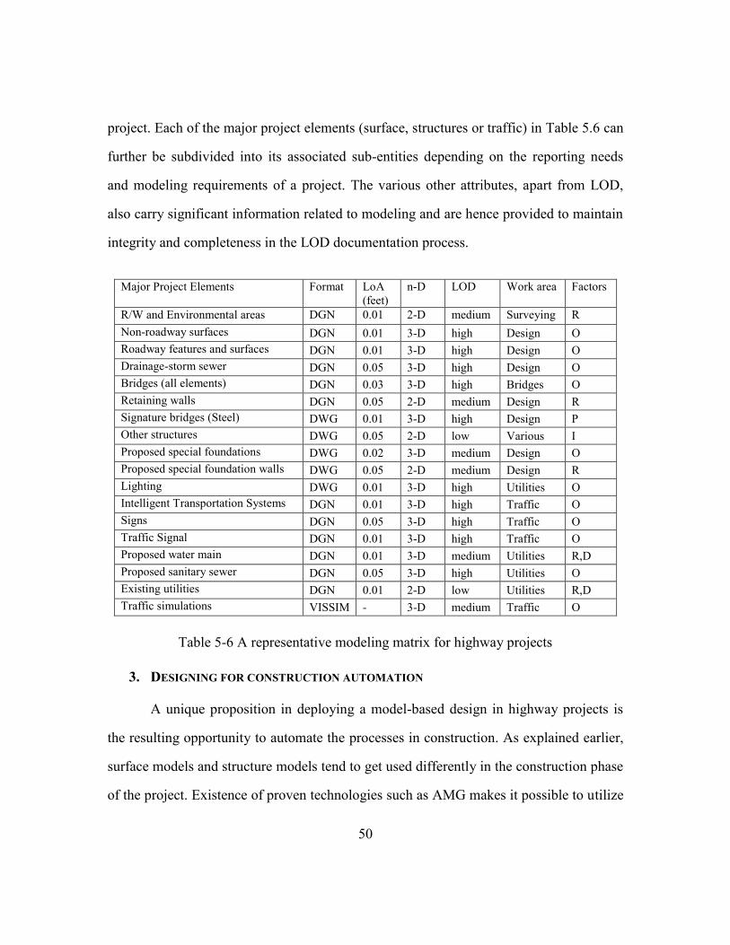
50
project. Each of the major project elements (surface, structures or traffic) in Table 5.6 can
further be subdivided into its associated sub-entities depending on the reporting needs
and modeling requirements of a project. The various other attributes, apart from LOD,
also carry significant information related to modeling and are hence provided to maintain
integrity and completeness in the LOD documentation process.
Major Project Elements Format LoA
(feet)
n-D LOD Work area Factors
R/W and Environmental areas DGN 0.01 2-D medium Surveying R
Non-roadway surfaces DGN 0.01 3-D high Design O
Roadway features and surfaces DGN 0.01 3-D high Design O
Drainage-storm sewer DGN 0.05 3-D high Design O
Bridges (all elements) DGN 0.03 3-D high Bridges O
Retaining walls DGN 0.05 2-D medium Design R
Signature bridges (Steel) DWG 0.01 3-D high Design P
Other structures DWG 0.05 2-D low Various I
Proposed special foundations DWG 0.02 3-D medium Design O
Proposed special foundation walls DWG 0.05 2-D medium Design R
Lighting DWG 0.01 3-D high Utilities O
Intelligent Transportation Systems DGN 0.01 3-D high Traffic O
Signs DGN 0.05 3-D high Traffic O
Traffic Signal DGN 0.01 3-D high Traffic O
Proposed water main DGN 0.01 3-D medium Utilities R,D
Proposed sanitary sewer DGN 0.05 3-D high Utilities O
Existing utilities DGN 0.01 2-D low Utilities R,D
Traffic simulations VISSIM - 3-D medium Traffic O
Table 5-6 A representative modeling matrix for highway projects
3. DESIGNING FOR CONSTRUCTION AUTOMATION
A unique proposition in deploying a model-based design in highway projects is
the resulting opportunity to automate the processes in construction. As explained earlier,
surface models and structure models tend to get used differently in the construction phase
of the project. Existence of proven technologies such as AMG makes it possible to utilize

51
the surface models to automate the downstream construction applications such as
excavating, grading, dozing, compacting and paving. Whereas, the structure models were
primarily used for design visualization, constructability reviews and other tasks that result
in better planning for construction. This difference is illustrated in Figure 5.5.
Figure 5.5 Automation usability in highway projects
The surveys also reported benefits and advantages of using this technology in
terms of improved productivity, safer jobsite, less re-work and accurate estimates of
earthwork operations. AMG also facilitates Construction Quality Control (CQC) and
inspection through Rover, a device that can be used to continuously perform QA/QC
checks comparing the model as against what is being built (McDaniel, 2014). Rovers can
also be used for performing quantity measurements. Higher initial cost of equipment and
its associated GPS components, lack of training and standards, and difficulty in

52
stakeholders buy-in (especially contractors) are some of the factors limiting usage of
AMG. Also, varying levels of expertise and expectations from the agencies (i.e. DOTs)
tend to produce different usage levels of 3-D models on projects. As an example, some of
the agencies provided the 3-D surface models for AMG during construction but had
placed an ―information only‖ clause transferring the liability and risk associated with
their usage for AMG to the contractor; In an another instance, an agency had not only
provided and mandated 3-D model for machine guidance but also given it higher priority
over 2-D plan sets in terms of contractually governing documents. A large portion of the
DOTs reported to be using AMG is primarily applying the technology for earthwork and
excavation related operations. Although machine XML files for finished surface elements
are provided to the contractor, non-availability of standardized guidelines for finished
surface elements and difficulties in contractors buy-in were reported to be the main
barriers hindering its widespread usage.
An important issue, as commonly agreed upon among all the survey participants,
for the AMG is the importance of designing the 3-D model with appropriate construction
specifications (deliverables and their formats). The general process followed here is
conversion of the required 3-D design related information – namely horizontal and
vertical alignments for the project, proposed surface (DTM), existing surface(DTM),
control points - to the appropriate file format for machine automation in the field.
Vonderohe et al. (2010) have developed specifications for design details and technical
specifications to be incorporated for effective AMG performance by the contractor.
Additionally, McDaniel (2014) has enlisted important process-oriented practices to be
followed while using AMG on projects. Emphasis has to be placed on the following
points: defining the ―model of record‖ for quantity verifications and QA/QC checks,
applicable usage of stakes for QA/QC, defining and following design tolerances for

53
various pavement elements, anticipated usage of stringless paving technology for
construction and associated technical specifications, ownership and calibration of rovers
for project purposes, and the list of files (with acceptable) formats to be provided to
contractor for implementing AMG in the field (McDaniel, 2014). For the agencies being
impacted due to high cost of rovers, FHWA (2014) have also provided recommendations
for the agencies’ staffs for doing QA/QC checks using contractor’s rovers. Vonderohe
(2013) mentioned the potential application areas of AMG for structures. They include
obtaining stakeout locations for control points of structural elements such as bridges and
retaining walls. However, not many projects have reported usage of machine control for
construction of major structural elements. Learning from these examples, it becomes
evident that agencies should develop standards for technological and process-oriented
issues regarding design for construction automation using AMG. Accordingly, the LOD
to be incorporated in surface models has to be given more significance.
An emerging technology that is enabling and complementing the usage of AMG
is equipment telematics. The telematics tool, when incorporated with construction
equipment such as excavators, dozers and graders can provide numerous benefits such as
improving machine utilization, real-time tracking of vehicles, reduce fuel consumption
and increase overall efficiency of the construction operation through an optimized fleet
management (Anderson, 2012). This web-based tool provides the ability to remotely
access the equipment data from office and also help upload the recent design files for
usage by the operators on the field. It also alerts the operators so that they always access
the latest version of the design information to perform their work. Higher initial cost, lack
of operators training, and non-availability of standards are some of the challenges facing
the widespread implementation of this technology.

54
4. DATA EXCHANGE TOOLS AND INFORMATION MANAGEMENT
While technology can provide us tools to facilitate the transition to digital project
delivery, equally important is having in place a robust and coherent information
management system (or standards) to organize and manage the information being
generated from various stakeholders throughout the project life-cycle. The broadening
technological capabilities of contemporary software packages assisted by increasing
computational capacity of computers have made it possible to model and analyze the
increasingly complex construction processes during the stages of project development.
These software tools possess the ability to accumulate and handle huge amounts of
information to the LOD desired. Data exchange between these tools is often mandated by
various stakeholders requesting same information for performing different tasks. A
proper information management system and exchange framework has a potential to allow
for greater collaboration between the stakeholders in a project and assist them in
performing their tasks in an efficient manner. Table 5.7 presents the options available for
consideration to state and federal transportation agencies towards standardization of
information and sharing of project related information among project participants and
facility managers.

55
Name Category of
tool
Description
TransXML Schema for
data
exchange
A NCHRP project (20-64) that resulted in development of
broadly accepted public domain XML schemas for
exchange of transportation data, and a framework for
development, validation, dissemination, and extension of
current and future schemas. It focused on four key business
areas (Ref: http://www.transxml.org/)
LandXML Schema for
data
exchange
An XML format for civil engineering design and survey
data to assist in data exchange between different software
applications and long-term data archival
(Ref: http://www.landxml.org/ )
CityGML Schema for
data
exchange
An Open Geospatial Consortium (OGC) standard for the
modelling and exchange of 3D city and landscape models
that is quickly being adopted on an international level.
(Ref: http://www.citygml.org/ ,
http://www.opengeospatial.org/standards/citygml )
Bentley
i-Model
Data
exchange
tool
It allows open exchange of infrastructure information and
enables project team members to share and interact with
complex project data and information, regardless of
different software platforms and location (office / field)
(Ref: http://www.bentley.com/en-US/Products/imodel/ )
Table 5-7 Existing standards to promote software interoperability and data exchange

56
Majority of the survey respondents reported to be using Bentley ProjectWise and/or
AASHTOware project to manage information pertaining to their projects. Some of the
agencies have also been using proprietary tools for data and files management on their
projects (such as an ALG file that belongs to Bentley Inrroads software or ProjectSolve
tool).
Information Modeling and Geospatial data collaboration
The issue of integrating GIS and information models has always been significant
since construction projects will benefit from such a context. Initiatives are underway
worldwide to formalize this process although literature doesn’t show a common agreed
framework. The objective of geospatial integration is challenging because of differences
in information standards, representation, utilization and exchange processes of the
constituent domains – namely CAD, urban planning and simulation, GIS based
visualizations and so on (Döllner & Hagedorn, 2007, p.1). Some of project phase /
activities that may benefit from integration as described by OGC(2011) include: initial
site planning through OGC standards based systems, including information about existing
and surrounding buildings through markup languages such as CityGML, performance of
detailed engineering studies and identifying conflicts by integrating BIM with
information of neighboring sites. One of the significant efforts to integrate information
and GIS has come from OGC Network (2011). They combined the capabilities of
CityGML and Industry Foundation Classes (IFC) for analyzing several details of
buildings in a geospatial context. This interoperability project also saw participation of
software giants such as Bentley.
Open standards for information exchange (such as IFC) for infrastructure
elements such as roads, bridges and tunnels are currently non-existent. However efforts

57
are being made to extend the IFC provisions to include representations for geometric and
semantic descriptions of the elements of infrastructure. Such an evolution will pave the
way for widespread implementation of 3-D design and geospatial integration.

58
Chapter 6 Discussion and Conclusion
The surveys performed at agency and project level helped in identifying the
important factors that could enable profitable implementation of CIM. It has to be noted
that the four factors discussed in this thesis do not make up the entire list of critical issues
for successful life-cycle implementation. Nevertheless, they were inferred from the
empirical data based on the consensus among the respondents and are hence applicable in
general to all transportation projects.
The recommendations proposed herein for technology implementation planning
clearly articulates the necessary components when preparing to implement a system of
technologies in a project (or throughout the agency) across its several work disciplines.
The need for the two levels of planning – organizational and project-level – was
emphasized in order to ensure predictability and reduce uncertainty in project
performance. Also, it will help improve the efficiency of the process of agency-wide
adoption of CIM technologies by ensuring greater transparency at the executive and the
project level.
The discussions on model-based workflow underlined the importance of
development of a TFP matrix that can provide valuable insights about understanding the
affected departments or areas due to CIM implementation. Processes requiring further
improvements can be clearly identified and appropriate control measures can be devised.
This simple, intuitive tool can serve as a basis towards formulation and validation of an
information flow model on digital projects. Formal recommendations for ascertaining and
documenting LOD on highway projects were also provided. The proposed methodology
for LOD seeks to address the most common problem in a model-based highway project
as reported by the survey respondents. It can also act as a standard language for
59
communication among project participants in the issues concerning model elements.
Practitioners can improve upon and/or customize the guidelines provided herein to
systematically incorporate them in contracts.
Designing for construction automation is considered a significant issue in the
highway industry. In this study, necessary data requirements and deliverables to perform
a 3-D design were illustrated. Existence of AMG technology for guiding various
pavement operations presents opportunities in terms of improving the productivity and
site safety. The discussions provided a clear understanding on the related factors such as
QA/QC checks using Rovers and contract clauses. Although this technology is currently
being used predominantly for earthwork operations, development of standards for
finished surfaces and contractors’ buy-in can promote its widespread application.
Executing projects through a model-based workflow will require robust data
exchange tools and information management systems to handle the large amount of data
generated. The discussion on this topic described the current challenges and available
solutions to make this process reliable and efficient. The concept of GIS and CIM
integration was investigated by outlining the current practices in this area and potential
advancements in the future.
RECOMMENDATION FOR FUTURE WORK
The current findings are expected to guide practitioners in understanding the
major issues that underlie the system of CIM technologies. The research process on the
chosen topic is ongoing. Detailed case studies are being performed on selected projects
and agency-related tools that have contributed towards successful CIM integration with
project delivery processes. This will enhance the current understanding on specific
benefits and challenges related to CIM applications and also validate and extend the list

60
of life-cycle issues. It will also help develop detailed information flow model for digital
project delivery and asset management.
Future research can focus upon evaluating the strategies and developing
implementation guidelines for CIM adapted to various project delivery methods.
Contracting strategies often regulate the mechanism and specifications under which
different stakeholders collaborate on a project. Hence, it can be an important life-cycle
factor that would contribute to understanding the CIM impacts on project work processes.
Quantitative assessment of performance benefits (or ROI) is another interesting research
area that can aid practitioners in making investment decisions for CIM. Although a
challenging task to quantify, a comprehensive and qualitative understanding of the
processes enhanced due to technologies’ implementation can complement the existing
knowledge in justifying important decisions. Formulation of maturity assessment models
for CIM can also be a significant focus area. It would assist agencies evaluate the current
level of CIM integration with their business processes and propose the path ahead for
improvement

61
Appendices:
CIM
Technological requirements
Planning & Surveying phase Design phase Procurement/Construction O&M Phase
1. Integrated survey -
LiDAR/APS/GPS/ALS/Robotic
Total stations/DL, 3D Laser
scanners,
2. Process: Data acquisition,
adjustment, classification,
mapping and viewing.
3. RFID/GPR Subsurface utility
marking, multi-sensor
platforms for utility locating –
integration with Utility
Relocation Document
Management Systems
(UREDMS), EMI, pipe and
cable locators, 3-D radar
tomography, UCM
4. Integration with design phase
1. Electronic document approval
system
2. Utility location and risk
management (continued from
surveying phase)
3. 3 - D engineered models
4. Model-based clash detection
process
5. 4- D simulation based construction
sequencing
6. 5 - D Cost estimating and
validation process
7. 6 - D specifications
8. Support for construction bid docs
9. Public information (visualization)
10. Traffic simulation and safety
analysis (VISSIM, Paramics)
11. Earthwork balancing and other
software applications
12. Support for integration with
construction phase
1. RFID/Barcodes for materials/data
tracking
2. 4-D simulation –schedule validation
3. Accelerated construction techniques
4. Precast/modular construction
5. AMG / AMC
6. Automated Plant Operations
7. String-less concrete paving technology
and equipment
8. Intelligent compaction
9. Online real time materials QC reporting
– GIS based CQM.
10. Real-time verification during
inspections – using handheld computers
11. Equipment Telematics
12. “Smart lube” Trucks
13. Public information (detours/closures)
through high-end visualization
14. Integrate with O&M
1. As-built documentation
2. Digital asset management
database – software or
web-based programs.
3. Electronic wage rate
verification
4. Public relations
Other requirements (common to all phases)
Contractual Legal
Alternative PDM such as D - B, CM/GC, CM at Risk, ATC, Lane rental,
warranty clauses.
• Dispute resolution clauses, digital signatures for engineering documents
• Liability of plans, survey data, as-built information, intellectual rights
Table A 1 A synopsis of CIM technologies classified by Project phases

62
Table 4.2: CIM – A compilation of Benefits and challenges
Benefits Challenges/concerns
1. Lower cost and duration of surveying
2. Clash detection (spatial/temporal), Visualization
3. Design-construction oversight collaboration
4. Digital modeling of existing & proposed
roadways/structures, utilities, surface information, digital
Facility Management database.
5. Reduction in RFIs , change orders - calculated as % ROI
6. 4D simulation based construction sequencing and conflicts
identification – constructability
7. Support for fabrication
8. Early contractor inputs for issue resolution
9. Reduction in rework at all phases of the project especially
during design and construction
10. Utilities relocation and risk mitigation
11. Faster response to change in scope of work
12. Ability to meet compressed schedules, constrained budgets
13. Enhanced coordination among trades
14. Enhanced construction productivity, site safety
15. Good support to construction and bid documents
16. Online real-time information regarding facility at all
phases of the project
1. Lack of standard applications or specifications for modern
surveying methods
2. Learning curve and initial adoption issues
3. Government regulations ( regarding contract methods)
4. High initial cost ( setup for software and hardware, training for
labor-force)
5. Perception among major stakeholders concerning
implementing BIM on smaller pilot projects
6. Legal and propriety issues surrounding digital project delivery
(Ownership of 3D model etc.)
7. Lack of internal understanding and organizational
requirements for digital delivery project requirement among
owners
8. Concerns regarding software interoperability – file formats
9. Evolution of understanding regarding legal and insurance risks
with CIM implementation
Table A 2 A compilation of benefits and challenges of CIM technologies

63
References
1. AIA. (2008). Design Build State Statute Compendium. The American Institute of
Architects (AIA). Retrieved from
http://www.aia.org/aiaucmp/groups/aia/documents/pdf/aias078886.pdf
2. AIA. (2013a). Building Information Modeling and Digital Data Exhibit. Retrieved
from http://www.aia.org/aiaucmp/groups/aia/documents/pdf/aiab099084.pdf
3. AIA. (2013b). Project Building Information Modeling Protocol Form. Retrieved
from http://www.aia.org/aiaucmp/groups/aia/documents/pdf/aiab099086.pdf
4. Anderegg, R., & Kaufmann, K. (2004). Intelligent Compaction with Vibratory
Rollers: Feedback Control Systems in Automatic Compaction and Compaction
Control. Transportation Research Record: Journal of the Transportation
Research Board, 1868, 124–134. doi:10.3141/1868-13
5. Anderson, R. (2012, June). Civil Integrated Management. Presented at the CIM
Training Expo, Florida. Retrieved from
http://www.dot.state.fl.us/structures/DesignExpo2012/CIMPresentations/CIM%2
0Presentation%20%20Jun%20%202012.pdf
6. Autodesk. (2007). BIM’s Return on Investment. Retrieved from
http://images.autodesk.com/emea_s_main/files/gb_revit_bim_roi_jan07.pdf
7. Azhar, S. (2011). Building information modeling (BIM): Trends, benefits, risks,
and challenges for the AEC industry. Leadership and Management in
Engineering, 11(3), 241–252.
8. Barlish, K., & Sullivan, K. (2012). How to measure the benefits of BIM—A case
study approach. Automation in Construction, 24, 149–159.
9. Bedrick, J. (2008). Organizing the Development of a Building Information Model.
Retrieved from http://www.aia.org/groups/aia/documents/pdf/aiab078868.pdf
10. BIMForum. (2013). LEVEL OF DEVELOPMENT SPECIFICATION. Retrieved
from http://bimforum.org/wp-content/uploads/2013/08/2013-LOD-
Specification.pdf

64
11. BIM Task Group. (2011). BIS BIM Strategy Report. UK. Retrieved from
http://www.bimtaskgroup.org/wp-content/uploads/2012/03/BIS-BIM-strategy-
Report.pdf
12. Chang, G. (2011). Accelerated Implementation of Intelligent Compaction
Technology for Embankment Subgrade Soils, Aggregate Base, and Asphalt
Pavement Materials (No. FHWA-IF-12-002). Federal Highway Administration
(FHWA). Retrieved from
http://www.fhwa.dot.gov/pavement/ic/pubs/hif12002.pdf
13. CIC. (2010). BIM Project Execution Planning Guide Version 2.0. The Computer
Integrated Construction (CIC), Pennsylvenia State University. Retrieved from
http://www.engr.psu.edu/bim/PxP
14. CTC & Associates LLC. (2010). LiDAR Applications for Transportation
Agencies. Wisconsin Department of Transportation (WisDOT). Retrieved from
http://wisdotresearch.wi.gov/wp-content/uploads/tsrlidarapplications1.pdf
15. DeVries, M. (2012, September). Civil Integrated Management - New
Technologies and Legal Risks. Retrieved from
http://www.stites.com/content/uploads/learning-
center/Devries_ARTBA_National_Sept_2012.pdf
16. Döllner, J., & Hagedorn, B. (2007). Integrating urban GIS, CAD, and BIM data
by servicebased virtual 3D city models. R. E. al.(Ed.), Urban and Regional Data
Management-Annual, 157–160.
17. Eastman, C. M., Teicholz, P., Sacks, R., Liston, K., & Handbook, B. I. M. (2008).
A Guide to Building Information Modeling for Owners, Managers, Architects,
Engineers, Contractors, and Fabricators. John Wiley and Sons, Hoboken, NJ.
18. Ellsworth, P. (2012). Utah DOT Leveraging LiDAR for Asset Management Leap.
Utah Department of Transportation (UDOT). Retrieved from
https://www.udot.utah.gov/public/ucon/uconowner.gf?n=8336606666333974
19. Farr, C. (2013, August 14). MDOT e-Construction. Presented at the 2013
AASHTO Subcommittee on Construction Annual Meeting. Retrieved from
http://construction.transportation.org/Documents/Meetings/e-Construction-Farr-
CT.pdf

65
20. FHWA. (2012a, April). CIVIL INTEGRATED MANAGEMENT (CIM).
Retrieved from http://www.efl.fhwa.dot.gov/files/technology/dv/CIM-Poster-
04.12.pdf
21. FHWA. (2012b, May 18). Alternative Technical Concepts. Retrieved September
18, 2014, from http://www.fhwa.dot.gov/everydaycounts/edctwo/2012/atc.cfm
22. FHWA. (2013a). 3D, 4D, and 5D ENGINEERED MODELS FOR
CONSTRUCTION. Federal Highway Administration (FHWA). Retrieved from
http://www.fhwa.dot.gov/construction/pubs/hif13048.pdf
23. FHWA. (2013b). Automated Machine Guidance with Use of 3D Models. Federal
Highway Administration (FHWA). Retrieved from
http://www.fhwa.dot.gov/construction/pubs/hif13054.pdf
24. FHWA. (2013c). Intelligent Compaction. Federal Highway Administration
(FHWA). Retrieved from
http://www.fhwa.dot.gov/construction/pubs/hif13051.pdf
25. FHWA. (2014a, April 2). Construction Manager General Contractor. Retrieved
September 18, 2014, from
https://www.fhwa.dot.gov/everydaycounts/edctwo/2012/cmgc.cfm
26. FHWA. (2014b, April 2). Design-Build. Retrieved September 18, 2014, from
http://www.fhwa.dot.gov/everydaycounts/edctwo/2012/designbuild.cfm
27. FHWA. (2014c, June 5). Background for Pavement Warranties - Pavement.
Retrieved September 18, 2014, from
http://www.fhwa.dot.gov/pavement/warranty/backgrnd.cfm
28. Guo, F., Turkan, Y., Jahren, C. T., & David Jeong, H. (2014). Civil Information
Modeling Adoption by Iowa and Missouri DOT. In 2014 International
Conference on Computing in Civil and Building Engineering. Retrieved from
http://ascelibrary.org/doi/abs/10.1061/9780784413616.058
29. Hartmann, T., Gao, J., & Fischer, M. (2008). Areas of Application for 3D and 4D
Models on Construction Projects. Journal of Construction Engineering and
Management, 134(10), 776–785. doi:10.1061/(ASCE)0733-
9364(2008)134:10(776)
66
30. Hartmann, T., Van Meerveld, H., Vossebeld, N., & Adriaanse, A. (2012).
Aligning building information model tools and construction management
methods. Automation in Construction, 22, 605–613.
31. Jeong, H. S., Arboleda, C. A., Abraham, D. M., Halpin, D. W., & Bernold, L. E.
(2003). Imaging and Locating Buried Utilities. Retrieved from
http://docs.lib.purdue.edu/jtrp/114/
32. Kang, Y., O’Brien, W. J., & Mulva, S. P. (2013). Value of IT: Indirect impact of
IT on construction project performance via Best Practices. Automation in
Construction, 35, 383–396. doi:10.1016/j.autcon.2013.05.011
33. Khwaja, N., & Schmeits, C. (2014). Improving the Transparency of Construction
Projects Through Visualization Technology. Transportation Research Record:
Journal of the Transportation Research Board, 2408, 34–43. doi:10.3141/2408-
05
34. Leite, F., Akcamete, A., Akinci, B., Atasoy, G., & Kiziltas, S. (2011). Analysis of
modeling effort and impact of different levels of detail in building information
models. Automation in Construction, 20(5), 601–609.
35. Liapi, K. . (2003). 4D visualization of highway construction projects. In Seventh
International Conference on Information Visualization, 2003. IV 2003.
Proceedings (pp. 639–644). doi:10.1109/IV.2003.1218054
36. McDaniel, R. (2014). Construction Inspection with Stakeless Technology.
Retrieved from http://www.efl.fhwa.dot.gov/files/technology/dv/2014-
Construction-Discipline-WinterTraining.pdf
37. Norby, D. (2013). Investments In Subsurface Utility Mapping Technology Means
Big Savings For Cities. Retrieved September 18, 2014, from
http://www.berntsen.com/Blog/entryid/23/subsurface-utility-mapping-technology-
means-big-savings-for-cities
38. O’Brien, W., Gau, P., Schmeits, C., Goyat, J., & Khwaja, N. (2012). Benefits of
Three- and Four-Dimensional Computer-Aided Design Model Applications for
Review of Constructability. Transportation Research Record: Journal of the
Transportation Research Board, 2268, 18–25. doi:10.3141/2268-03

67
39. O’Connor, J. T., & Yang, L.-R. (2004). Project performance versus use of
technologies at project and phase levels. Journal of Construction Engineering and
Management, 130(3), 322–329.
40. ODOT. (2012). Oregon DOT 3D Roadway design. Retrieved from
http://www.oregon.gov/odot/hwy/3drdm/Pages/index.aspx
41. OGC Network. (2011). OWS-4 CAD/GIS/BIM. Retrieved September 18, 2014,
from http://www.ogcnetwork.net/node/236
42. Oldenburg, R. (2011). 3D Modeling and 4D Simulation: Mitchell Interchange
Construction/Zoo Interchange Design, SE Freeways, Wisconsin. Autodesk
University. Retrieved from http://au.autodesk.com/au-online/classes-on-
demand/class-catalog/2011/autocad-civil-3d/3d-modeling-and-4d-simulation-
mitchell-interchange-constructionzoo-interchange-design-se-freeways-wisconsin
43. Parve, L. (2012, August 23). CIM-Civil Integrated Management: Best Practices
& Lessons Learned. Presented at the 3D Modeling, Wisconsin. Retrieved from
http://www.efl.fhwa.dot.gov/files/technology/3d-
modeling/Thursday_Meeting/Lance-Parve.pdf
44. Parve, L. (2014, April 2). Supporting 3D/4D Construction Applications in
Preconstruction. Presented at the FHWA 3D Engineered models webinar series.
Retrieved from http://www.fhwa.dot.gov/construction/3d/webinars/webinar04.pdf
45. Porwal, A., & Hewage, K. N. (2013). Building Information Modeling (BIM)
partnering framework for public construction projects. Automation in
Construction, 31, 204–214.
46. Quiroga, C., Kraus, E., Scott, P., Swafford, T., Meis, P., & Monday, G. (2012).
Identification of Utility Conflicts and Solutions. SHRP 2 Report, (S2-R15B-RW-
1). Retrieved from http://trid.trb.org/view.aspx?id=1222351
47. Ralls, M. L. (2013). Committee for Intelligent Construction Systems and
Technology: Program Review Letter Report. V/ashington, D.C: Transportation
Research Board. Retrieved from
http://onlinepubs.trb.org/onlinepubs/reports/ICST_Nov_2013.pdf
48. Singh, R. (2008). Engineering Automation: Key Concepts for a 25 Year Time
Horizon. Oregon Department of Transportation (ODOT), Highway Division.
68
49. Singh, R. (2013, September 13). LiDAR to Machine - Automated 3D
infrastructure Construction and Management. Presented at the ASCE
Construction Institute Summit, Dallas, Tx.
50. Thomas, L. W. (2013). Legal Issues Surrounding the Use of Digital Intellectual
Property on Design and Construction Projects. Retrieved from
http://trid.trb.org/view.aspx?id=1247085
51. Vonderohe, A. (2013). Wisconsin Department of Transportation 3D
Technologies Implementation Plan. University of Wisconsin – Madison:
Construction and Materials Support Center. Retrieved from
http://cmsc.engr.wisc.edu/WisDOT-3D-Technologies-Implementation-Plan-Final-
Plan-2013-July-1.pdf
52. Vonderohe, A., Zogg, J., Whited, G., & Brockman, K. (2010). Planning the
Implementation of Three-Dimensional Technologies for Design and Construction.
Transportation Research Record: Journal of the Transportation Research Board,
2183, 129–138. doi:10.3141/2183-14
53. Washington Departmant of Transportation. (2014). Lane Rental. Retrieved
September 18, 2014, from
http://www.wsdot.wa.gov/Projects/delivery/alternative/LaneRental.htm
54. Wei, T., & Jarboe, P. (2010). Integration of Traffic Simulation into Design
Visualization. Transportation Research Record: Journal of the Transportation
Research Board, 2165, 89–95. doi:10.3141/2165-10
55. Williams, K., Olsen, M. J., Roe, G. V., & Glennie, C. (2013). Synthesis of
Transportation Applications of Mobile LIDAR. Remote Sensing, 5(9), 4652–
4692.
Top Related