


Languages
Pages
Legal


We build a better future!
CONTENTS
General _ 04L 1 PanelWithdrawable System _ 07S 1 PanelWithdrawable Units _ 10Withdrawable System _ 14

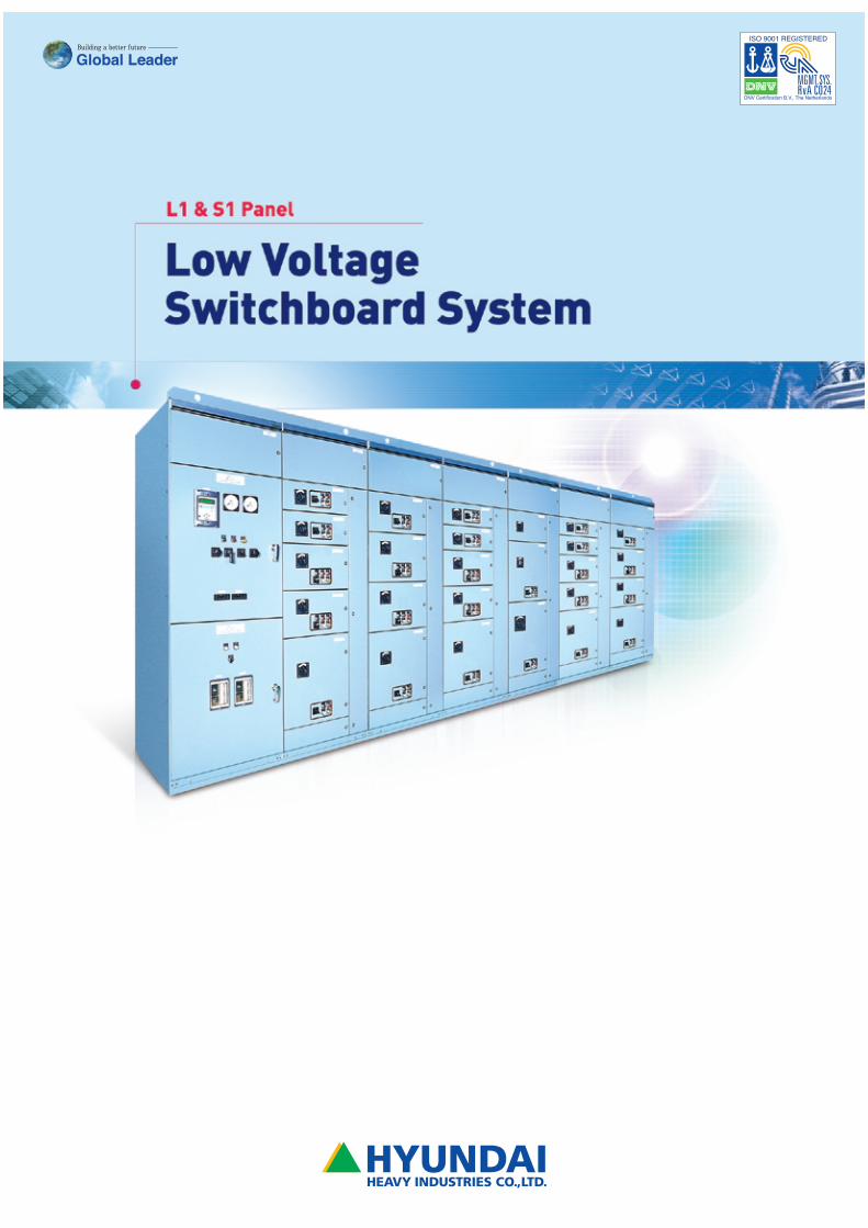
HYUNDAI’s low voltage motor control center H8PU series
with a withdrawable unit are of multi-tier, factory assembled
and for rated voltage of up to 660 V AC.
L1 Panel&
S1 Panel GeneralLo
w V
olta
ge S
witc
hboa
rd S
yste
m
04
Standard SpecificationsThe H8PU low voltage switchgear is in line with VDE
0660, Part 5/11.67 (covering FBAs with rated voltages of
up to 1000 V a.c. or 3000 V d.c.) and IEC publication
60439-1-2004.
Its creepage distances and clearances in air meet the
requirements of:
a) VDE 0110, class C insulation for 1000 V, 40 to 60 Hz
b) NEMA publication ICS2 - 322 for 600 V system voltage
c) CSA C22.2 No.14 - 1966 for 600 V system voltage
d) UL 508 table 18.2 for 600 V system voltage
e) BS 5486 : Part 1 : 1977 for 600 V system voltage
f) IEC 60439-1-2004, clause 8,2,5
1) active parts in the supporting structure insulated in accordance with VDE 0110, group C for 1000 V a.c., 40 to 60 Hz2) with outdoor enclosure, it is possible to provide IP54 degree of protection.
General Information
Rated voltage
Rated operational current
horizontal (main) busbars up to 4000 A
vertical dropper bars 650 A, 850 A
Withdrawable units with
contactor up to 250 A
contactors for reversing up to 250 A
contactors for star-delta-starting up to 240 A
contactors for pole-changing up to 110 A
load-break switch with HRC-fuses up to 400 A
withdrawable circuit breaker up to 4000 A
fixed mounted circuit breaker up to 4000 A
Short circuit strength
horizontal (main) busbars up to 83 kA
vertical dropper bars up to 65 kA
Degree of protection according to standard : IP40, IP50
IEC publ. 529. option : IP41, IP51, IP42, IP54 2)
Tropicalised paint finish, both inside and outside : Munsell no 7.5 BG 6/1.5, Ral 7032 (option)
Designed for Indoor installation, against a wall or freestanding
660 V, 40 to 60 Hz 1)
L1 Panel
Low
Vol
tage
Sw
itchb
oard
Sys
tem
05
Application- Incoming supply
- Outgoing feeder
- Bus coupler (bus section switching)
- Bus coupler (double bar system coupling)
Component RangeWithdrawable circuit breakers, HAT 06 to HAT 40
(or HiAN 06 to HiAN 32) hand operated or storage
type motor mechanism
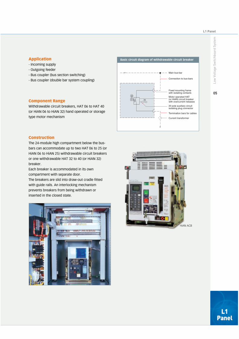
ConstructionThe 24-module high compartment below the bus-
bars can accommodate up to two HAT 06 to 25 (or
HiAN 06 to HiAN 25) withdrawable circuit breakers
or one withdrawable HAT 32 to 40 (or HiAN 32)
breaker.
Each breaker is accommodated in its own
compartment with separate door.
The breakers are slid into draw-out cradle fitted
with guide rails. An interlocking mechanism
prevents breakers from being withdrawn or
inserted in the closed state.
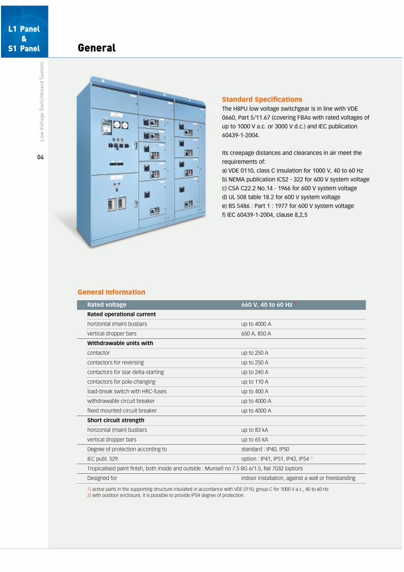
Basic circuit diagram of withdrawable circuit breaker
M
20
Main bus-bar
Connection to bus-bars
Fixed mounting framewith isolating contacts
Motor operated HAT(or HiAN) circuit breaker with overcurrent releases
20 pole auxiliary circuitisolating plug connector
Termination bars for cables
Current transformer
L1 Panel
HiAN ACB

General
Draw-out Cradle and WithdrawableCircuit BreakersThe draw-out mechanism permits to draw-out and
remove the breaker body from the draw-out cradle
and to put the breaker body back into the cradle.
Breakers with screwed positioning spindle can be
moved by turning of the draw-out handle from the
connected to the test position.
The auxiliary switch assembly mounted on the
draw-out cradle works in the CONN. and TEST
position.
Shutters (Protection against Touch)The fixed isolating contacts of withdrawable circuit
breakers can be blanked off by automatically
actuated shutters.
These cover any normally live parts, e.g.
connecting bars and fixed contacts, which would
be exposed when the breaker has been
withdrawn.
The top shutter and bottom shutter are
independent. Each shutter can be padlocked in the
closed position for safety during inspection and
maintenance.
The top shutter and bottom shutter can be opened
or closed independently by manual operation.
Maintenance can be done in the open position
(The mechanism is released automatically by
inserting the breaker).
The control circuit's disconnected contacts have
independent shutters for increased safety.
Control circuit safety shutter
Low
Vol
tage
Sw
itchb
oard
Sys
tem
06
L1 Panel
Automatically actuated shutters infront of upper and lower isolatingcontacts.

Withdrawable System
Test/Isolated PositionAfter releasing the interlock, the breaker can be moved from the normal in-service position to the test
position, either by hand or by means of a screwed positioning spindle. In this position in which the
breaker can be relocked, the power circuits are disconnected but the auxiliary circuits remain made.
The breaker can now be tested for correct operation. When the auxiliary circuit isolating plug
connector is also withdrawn, the breaker is said to be in the fully isolated position. In both cases, the
compartment doors can be closed.
1. CONNECTED Position 2. TEST Position
Both main and control circuits are connected fornormal service.
The main circuit is isolated and the control circuits areconnected. This position permits operation tests with theswitchboard panel door closed.
3. ISOLATED Position 4. REMOVED Position
Both main and control circuits are isolated. The switchboard panel door can be closed.
The breaker is completely out of the cradle forremoval.
L1 Panel
Low
Vol
tage
Sw
itchb
oard
Sys
tem
07
Withdrawable System
Cable ConnectionsL1-panels are designed for cable entry from
bottom. The cables are connected to termination
bars at the bottom of the panel, accessible either
from the front or the rear, depending upon the
panel design. Current transformers can be
accommodated on these connecting bars between
the breaker and the cable terminations.
Breaker Lifting and Transporting TruckLifting trucks are available to simplify the handling
of breakers when they are withdrawn from their
compartment. The platform of the truck can be
raised to any breaker mounting level.
ReleaseEvery standard withdrawable circuit breaker is fitted with multi-function protection relay. In addition to three
overcurrent protective functions, (long time-delay, short time-delay and instantaneous), a ground fault
protective function can be incorporated within one device.
Model available - Panel dimensions
Front View Side View Side View Side View Side View Side View
Front View Side View Side View Side View Side View Side View
"W" "D" "D" "D"
"W"
ACB Flush mounted ACB Surface mounted
ACB Flush mounted ACB Surface mounted
"D" "D" "D"
"D" "D"
"D" "D"
*23
60*
2360
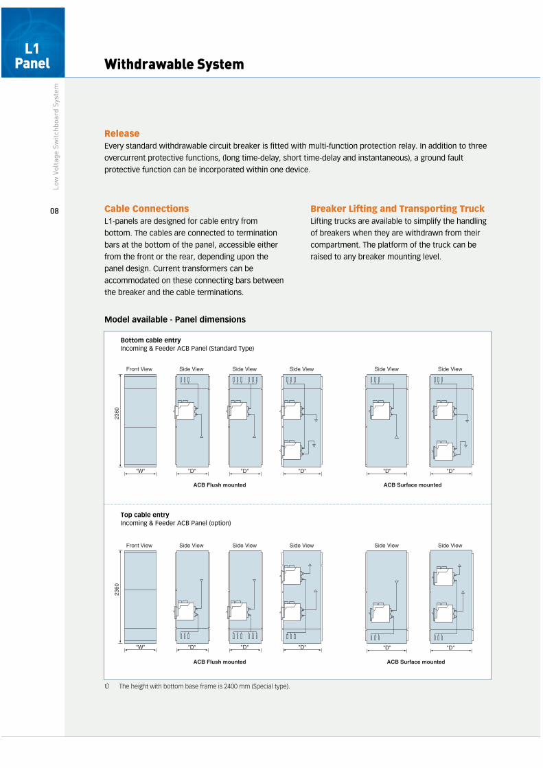
Bottom cable entryIncoming & Feeder ACB Panel (Standard Type)
Top cable entryIncoming & Feeder ACB Panel (option)
※*The height with bottom base frame is 2400 mm (Special type).
Low
Vol
tage
Sw
itchb
oard
Sys
tem
08
L1 Panel

Busbar data
ACB Frame
Panel depth(“D”)
HiAN 06~10HAT 06~10
HiAN 12HAT 12
HiAN 16HAT 16
HiAN 20HAT 20
HiAN 25HAT 25
HiAN 32HAT 32 HAT 40
Remark
800
1200
1600 (1500)**
●
●
●
●
●
●
●
●
●
●
●
●
-
●
●
-
●
●
-
●
●
1) Cable enterance : bottom2) ACB (Flush mounted)
ACB (Flush mounted)
ACB (Surface mounted)
ACB Frame
Panel wide(“W”)
HiAN 06~10HAT 06~10
HiAN 12HAT 12
HiAN 16HAT 16
HiAN 20HAT 20
HiAN 25HAT 25
HiAN 32HAT 32 HAT 40
Remark
800
1000
3 ph 3W3 ph 4W
-
3 ph 3W3 ph 4W
-
3 ph 3W3 ph 4W
-
3 ph 3W3 ph 4W
-
3 ph 3W
3 ph 4W
3 ph 3W
3 ph 4W
-
3 ph 3W3 ph 4W
※ - **Special type (Order made)- The 3 tier will be available for HAT 16 and below type.
Main busbars
Rated operatingcurrent (A)
800
1000
1200
1600
1900
2000
2500
3100
120
90
80
176
1502 x (20 x 10)
2 x (25 x 10)
2 x (40 x 10)
2 x (50 x 10)
2 x (60 x 10)
2 x (80 x 10)
2 x (100 x 10)
2 x (120 x 10)
12 x 4
Peak withstand current Cross-section(mm x mm)
Control circuitbusbars
Cross-section(mm x mm)Normal Standard (kA) Reinforced (kA)
L1 Panel
Low
Vol
tage
Sw
itchb
oard
Sys
tem
09
Withdrawable UnitsLo
w V
olta
ge S
witc
hboa
rd S
yste
m
10
Application- Motor feeder
- Incoming supply feeder for subdistribution boards
Component Range- D.O.L. contactor starter (normal start)
- D.O.L. contactor starter (heavy duty start)
- Reversing contactors
- Contactor-type star-delta starter
- Pole-changing starter
- Fused load-break switch / Moulded case circuit
breaker
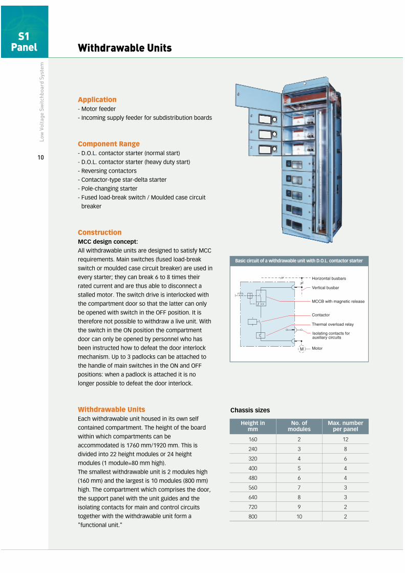
ConstructionMCC design concept:
All withdrawable units are designed to satisfy MCC
requirements. Main switches (fused load-break
switch or moulded case circuit breaker) are used in
every starter; they can break 6 to 8 times their
rated current and are thus able to disconnect a
stalled motor. The switch drive is interlocked with
the compartment door so that the latter can only
be opened with switch in the OFF position. It is
therefore not possible to withdraw a live unit. With
the switch in the ON position the compartment
door can only be opened by personnel who has
been instructed how to defeat the door interlock
mechanism. Up to 3 padlocks can be attached to
the handle of main switches in the ON and OFF
positions: when a padlock is attached it is no
longer possible to defeat the door interlock.
Withdrawable UnitsEach withdrawable unit housed in its own self
contained compartment. The height of the board
within which compartments can be
accommodated is 1760 mm/1920 mm. This is
divided into 22 height modules or 24 height
modules (1 module=80 mm high).
The smallest withdrawable unit is 2 modules high
(160 mm) and the largest is 10 modules (800 mm)
high. The compartment which comprises the door,
the support panel with the unit guides and the
isolating contacts for main and control circuits
together with the withdrawable unit form a
"functional unit."
Basic circuit of a withdrawable unit with D.O.L. contactor starter
Horizontal busbars
Vertical busbar
Contactor
Motor
MCCB with magnetic release
Thermal overload relay
Isolating contacts forauxiliary circuits
M
I
Chassis sizes
160
240
320
400
480
560
640
720
800
2
3
4
5
6
7
8
9
10
12
8
6
4
4
3
3
2
2
Height in mm
No. of modules
Max. number per panel
S1 Panel

S1 Panel
Low
Vol
tage
Sw
itchb
oard
Sys
tem
11
1. Each withdrawable unit is provided with its own
main switch. This is fitted with three isolating
contacts with plug on to the vertical bars of the
panel from which the unit's supply is derived.
2. Isolating contacts are also fitted to the
withdrawable units for the outgoing load
connections.
3. A set of 20 control circuit isolating contacts is
provided at the rear of the withdrawable unit;
these open automatically when the unit is
withdrawn. The terminations for the control
leads are of the screwless type.
4. With two swivelling levers, they are easy to
operate and are used to push the withdrawable
unit fully into the service position.
5. A hinged sub-panel is attached to the
withdrawable unit for control devices and
instruments. Complete access for maintenance
or setting purposes is thus provided to all
components with the compartment door open
and the subpanel swung out.
Vertical BusbarsPower is fed to the withdrawable units through the
isolating contacts of the main switch which plug
on to the vertical bars. "2" sizes of vertical bars are
available, rated 650 A, and 850 A respectively.
They are housed in an u-shaped duct and are
supported every 80 mm thus providing a peak fault
current rating of is = 130 kA.
Vertical bar sections : 60 X 6 mm, 60 X 8 mm
Protection against TouchingWhen the unit is withdrawn a shutter covers the
vertical bars. Inadvertent contact with the live bars
is thus prevented.
Interchangeability and ModificationsAll withdrawable units of the same size are
interchangeable irrespective of the equipment
which they contain. It is possible to change the
size of a compartment of an S1 panel while the
board is live; only simple tools are required.
Neither cutting nor drilling or welding are required,
all necessary holes and openings are already
provided. To change the size of a compartment it
is only necessary to exchange the compartment
door(❶), to move the horizontal support plate with
the chassis guides(❷), the fixed part of the 20-pole
control circuit isolating contacts(❸) into their new
positions, and to screw the fixed part of the load
isolating contacts(❹) into already existing holes.
1
5
2
❶
❷ ❸
❹
3
4
Withdrawable Units
Control SupplyFor control supply derived from a common transformer,
facilities are provided for the accommodation of up to 5
horizontal and up to 6 vertical control supply busbars.
Horizontal control supply bars are housed in a free space
below the busbars chamber.
The control supply is fed to the individual withdrawable
unit from up to 3 sets of vertical double pole control
busbars. They are fitted to the right-hand side of the
vertical bar duct(❶) and are connected to contacts in the
20-pole control circuit isolating plug(❷).
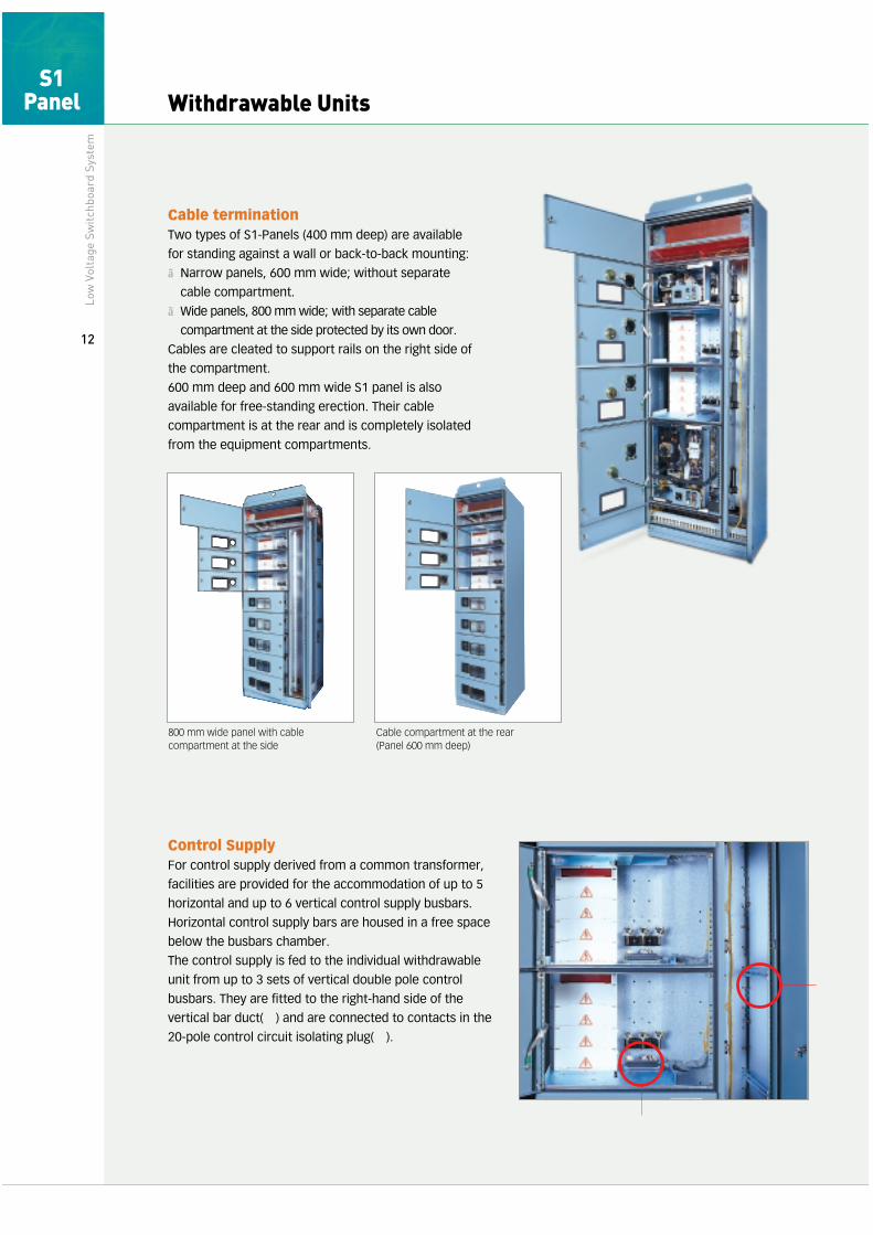
Cable terminationTwo types of S1-Panels (400 mm deep) are available
for standing against a wall or back-to-back mounting:
■Narrow panels, 600 mm wide; without separate
cable compartment.
■Wide panels, 800 mm wide; with separate cable
compartment at the side protected by its own door.
Cables are cleated to support rails on the right side of
the compartment.
600 mm deep and 600 mm wide S1 panel is also
available for free-standing erection. Their cable
compartment is at the rear and is completely isolated
from the equipment compartments.
800 mm wide panel with cablecompartment at the side
Cable compartment at the rear(Panel 600 mm deep)
Low
Vol
tage
Sw
itchb
oard
Sys
tem
12
S1 Panel
❷
❶

Test Situation and Isolating PositionTo test the operation of the equipment of any
withdrawable unit it is only necessary to open the
main switch. The withdrawable unit remains in its
operating position, all control circuit and supply
connections remaining made. (Test situation(❸))
By operating the swivel lever of the withdrawable
unit into position (❹) the unit will be moved to
isolated position. All connections to the
withdrawable unit are broken. When the unit is in
this position it is not possible to close the
compartment door.
Door lockEach door is fitted with one, two or three locks,
depending on its height. A standard double-bit key
for low voltage cubicles is used.
The special design of lock permits the door to
open slightly in the event of a pressure build-up
due to arcing but holds it firmly so that the
pressure can escape harmlessly.
BusbarsThe main busbars, which are made of copper, are
installed horizontally in the upper sub-section of
the compartment.
Each phase consists of two rectangular-section
conductors mounted side by side and on edge. In
all the section, the busbars are arranged at the
same the section front. This makes it possible to
combine sections of level and equidistant from
differing depths to form a switchboard with ready
aligned busbars and having a continuous front.
The busbars have supports of high quality
insulating material, which take the form of arc
barriers. This arrangement prevents an arc from
travelling from one busbar compartment into the
adjacent compartments.
Double-bit key
❶ Busbar supports (Moulded plastic)
❷ Main busbars
❸ Control circuit busbars
Arrangement of main busbars andcontrol circuit busbars.
❸
❹
S1 Panel
Low
Vol
tage
Sw
itchb
oard
Sys
tem
13
Withdrawable SystemLo
w V
olta
ge S
witc
hboa
rd S
yste
m
14
Standing against a narrow panel
•where space on site is limited
•front mounting is possible
•rear cabling access
•no separate cable compartment door
•re-cabling not possible whileboard is live
Standing against a wide panel
-
•front mounting is possible
•front cabling access
•separate cable compartmentdoor at the side
•re-cabling is possible with board live
Standing against a wall wide panel
-
•back-to-back mounting is possible
•front cabling access
•separate cable compartmentdoor at the side
•re-cabling is possible with board live
Front View Side View Front View Front View Front ViewSide View Side View Side View
Front View Side View Front View Front View Front ViewSide View Side View Side View
Rear conn. type Front only Back to back Back to back(Main bus : 4000 A)
Rear conn. type Front only Back to back Back to back(Main bus : 4000 A)
*23
60
*23
60*
2360
*23
60
*23
60*
2360
*23
60*
2360
600 600 800 800 800 800 800400
600 600 800 800 800 800 800400
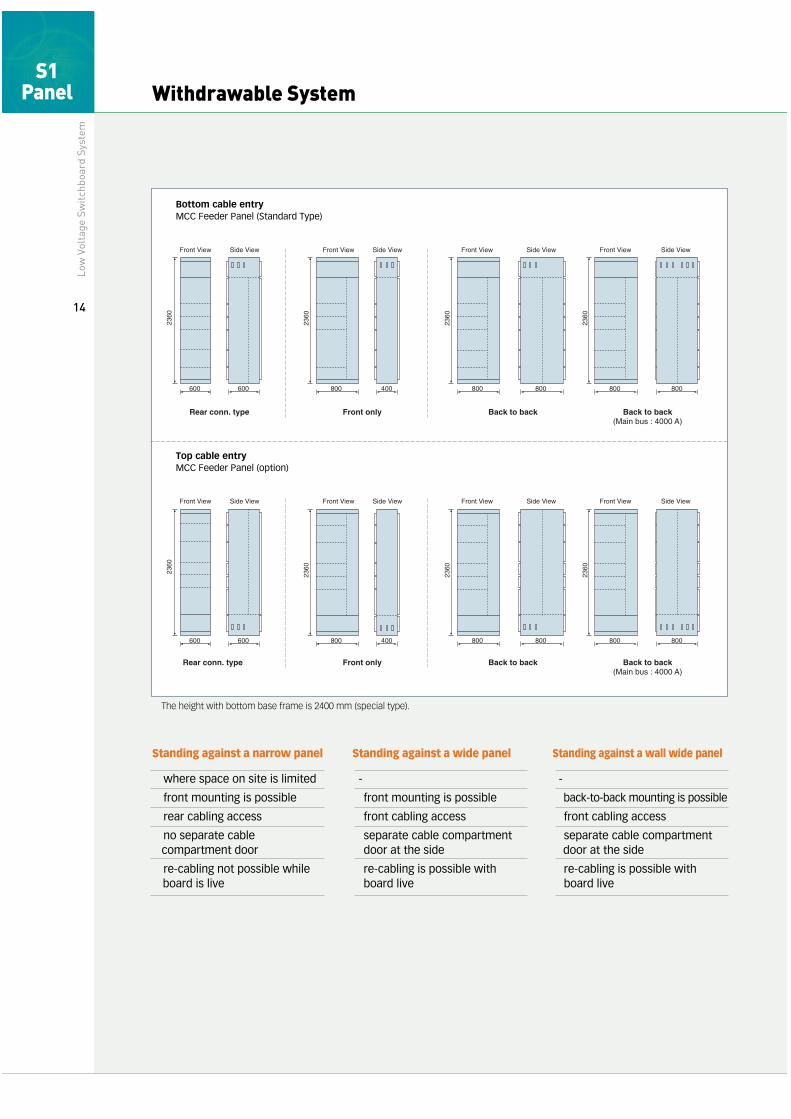
Bottom cable entryMCC Feeder Panel (Standard Type)
Top cable entryMCC Feeder Panel (option)
*The height with bottom base frame is 2400 mm (special type).
S1 Panel
Top Related