


Languages
Pages
Legal

Computer GraphicsModule Review
CO2409 Computer Graphics
Lecture ContentsLecture Contents
1. 2D Graphics & Geometry
2. 3D Geometry & Maths
3. Rendering Pipeline – Key Concepts
4. Programmable Pipeline / Shaders
5. Depth / Stencil Buffers & Shadows
6. Animation
Pixels & ColourPixels & Colour
• A computer display is made of a grid of small rectangular areas called pixels
• Pixel colour is usually specified as red, green and blue components:– Integers (0-255) or floats (0.0 to 1.0)
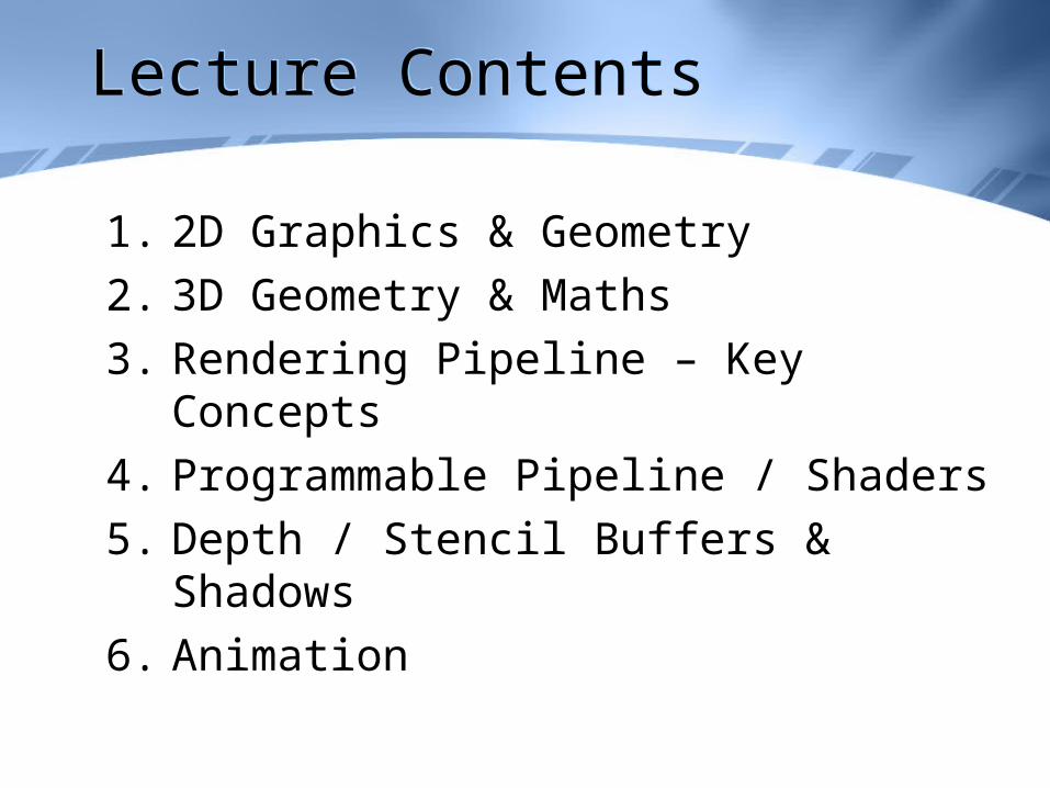
• The RGB ‘colour space’ is a cube• Another colour space is HLS
– Hue =colour from spectrum, Lightness = brightness of the colour Saturation = intensity of the colour
– Can be pictured as a double cone– More intuitive for artists
Bitmaps / Sprites / Alpha ChannelsBitmaps / Sprites / Alpha Channels
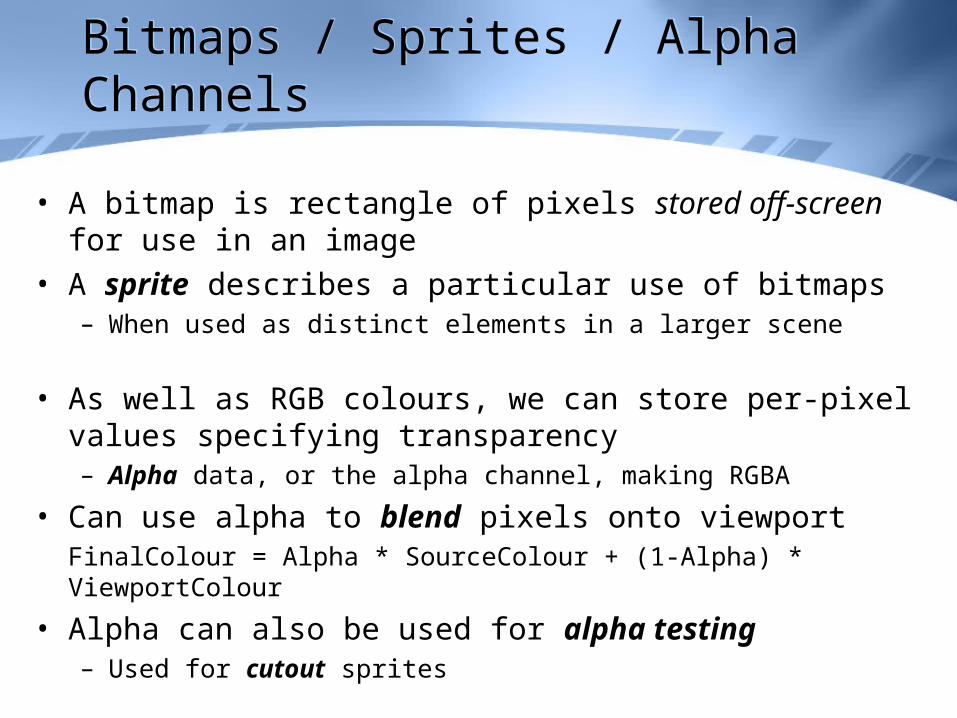
• A bitmap is rectangle of pixels stored off-screen for use in an image
• A sprite describes a particular use of bitmaps– When used as distinct elements in a larger scene
• As well as RGB colours, we can store per-pixel values specifying transparency– Alpha data, or the alpha channel, making RGBA
• Can use alpha to blend pixels onto viewportFinalColour = Alpha * SourceColour + (1-Alpha) * ViewportColour
• Alpha can also be used for alpha testing– Used for cutout sprites
Further BlendingFurther Blending
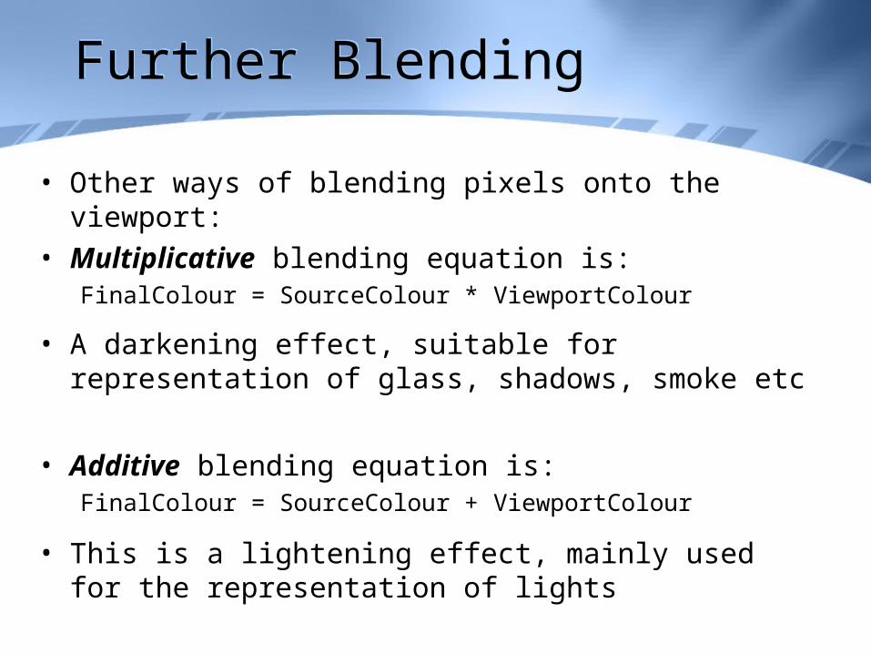
• Other ways of blending pixels onto the viewport: • Multiplicative blending equation is:
FinalColour = SourceColour * ViewportColour
• A darkening effect, suitable for representation of glass, shadows, smoke etc
• Additive blending equation is:FinalColour = SourceColour + ViewportColour
• This is a lightening effect, mainly used for the representation of lights
Basic Geometry DefinitionsBasic Geometry Definitions
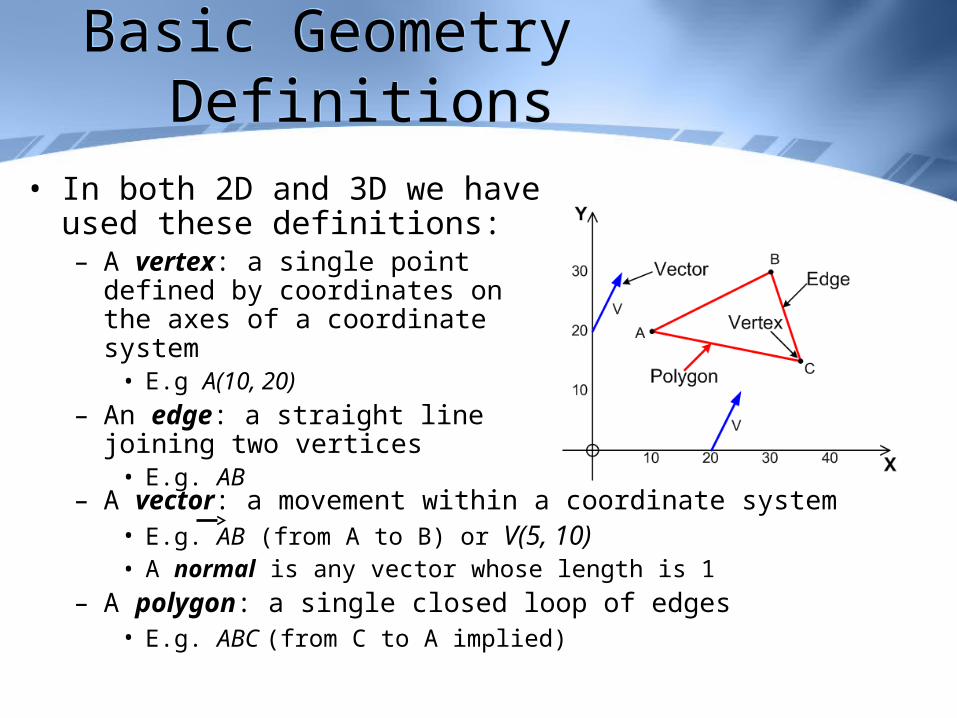
• In both 2D and 3D we have used these definitions:– A vertex: a single point defined by
coordinates on the axes of a coordinate system
• E.g A(10, 20)
– An edge: a straight line joining two vertices
• E.g. AB
– A vector: a movement within a coordinate system• E.g. AB (from A to B) or V(5, 10)• A normal is any vector whose length is 1
– A polygon: a single closed loop of edges • E.g. ABC (from C to A implied)
Coordinate SystemsCoordinate Systems
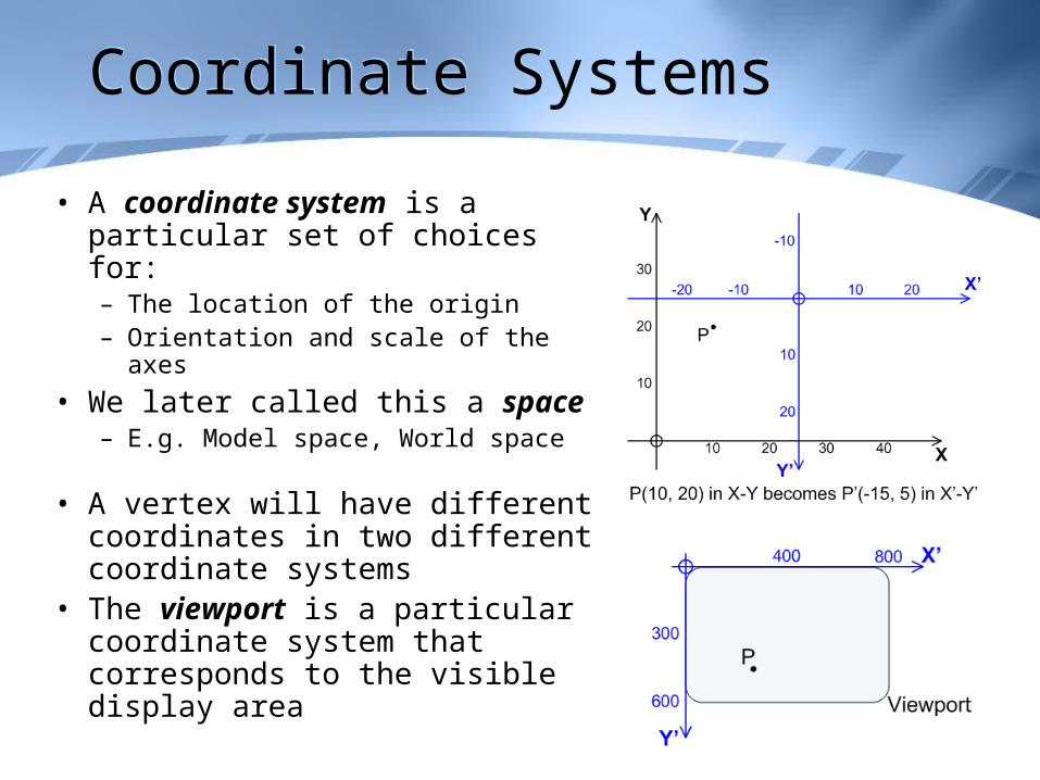
• A coordinate system is a particular set of choices for:– The location of the origin– Orientation and scale of the axes
• We later called this a space– E.g. Model space, World space
• A vertex will have different coordinates in two different coordinate systems
• The viewport is a particular coordinate system that corresponds to the visible display area
RenderingRendering
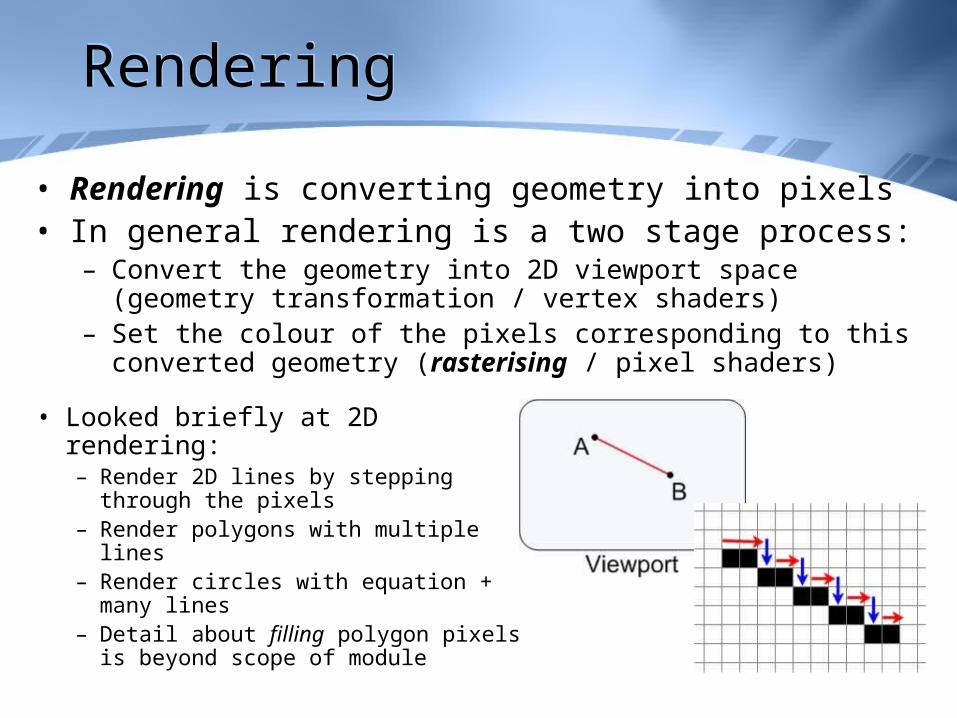
• Rendering is converting geometry into pixels• In general rendering is a two stage process:
– Convert the geometry into 2D viewport space (geometry transformation / vertex shaders)
– Set the colour of the pixels corresponding to this converted geometry (rasterising / pixel shaders)
• Looked briefly at 2D rendering:– Render 2D lines by stepping
through the pixels– Render polygons with multiple lines– Render circles with equation +
many lines– Detail about filling polygon pixels is
beyond scope of module
Maths/C++ for Graphics AppsMaths/C++ for Graphics Apps
• Be aware of numeric limitations in C++, e.g:– int limits can be exceeded– float / double have limited precision– Repeated calculations with float can build up errors– Other languages have similar limitations
• C++ automatically converts between numeric types, issuing warnings when it does– Don’t ignore, may not be what is required
• Several math functions used for graphics:– Max, min, remainders, modulus / absolute value, powers, cos, sin…– Know the library functions used
3D Geometry - Meshes / Normals3D Geometry - Meshes / Normals
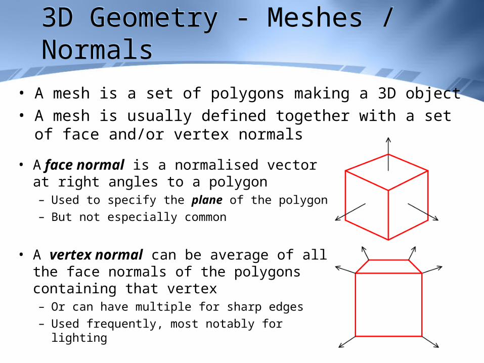
• A mesh is a set of polygons making a 3D object• A mesh is usually defined together with a set of face and/or
vertex normals
• A face normal is a normalised vector at right angles to a polygon– Used to specify the plane of the polygon– But not especially common
• A vertex normal can be average of all the face normals of the polygons containing that vertex – Or can have multiple for sharp edges– Used frequently, most notably for lighting
MatricesMatrices
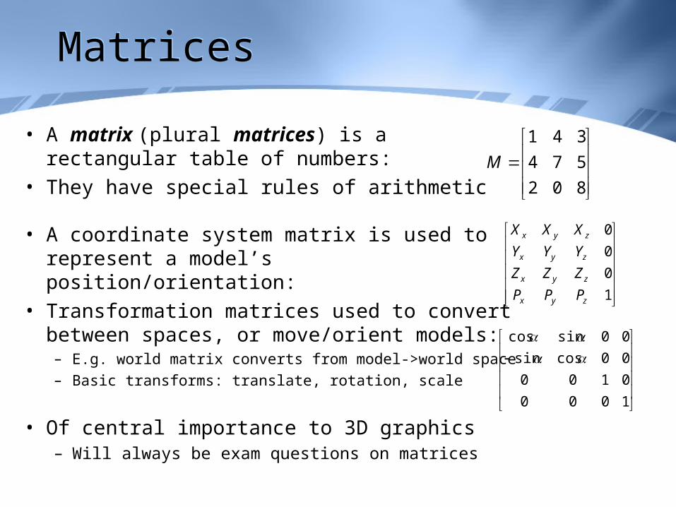
• A matrix (plural matrices) is a rectangular table of numbers:
• They have special rules of arithmetic
• A coordinate system matrix is used to represent a model’s position/orientation:
• Transformation matrices used to convert between spaces, or move/orient models: – E.g. world matrix converts from model->world space
– Basic transforms: translate, rotation, scale
• Of central importance to 3D graphics– Will always be exam questions on matrices
802
574
341
M
1
0
0
0
zyx
zyx
zyx
zyx
PPP
ZZZ
YYY
XXX
1000
0100
00cossin
00sincos
DirectX / Rendering PipelineDirectX / Rendering Pipeline
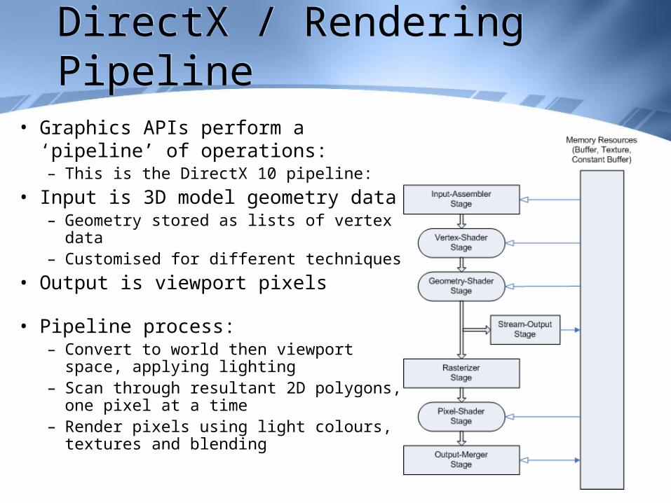
• Graphics APIs perform a ‘pipeline’ of operations:– This is the DirectX 10 pipeline:
• Input is 3D model geometry data– Geometry stored as lists of vertex data– Customised for different techniques
• Output is viewport pixels
• Pipeline process:– Convert to world then viewport space,
applying lighting– Scan through resultant 2D polygons,
one pixel at a time– Render pixels using light colours,
textures and blending
World MatrixWorld Matrix
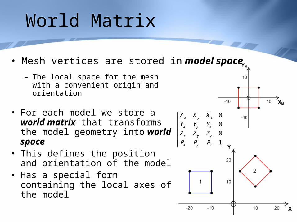
• Mesh vertices are stored in model space
– The local space for the mesh with a convenient origin and orientation
• For each model we store a world matrix that transforms the model geometry into world space
• This defines the position and orientation of the model
• Has a special form containing the local axes of the model
1
0
0
0
zyx
zyx
zyx
zyx
PPP
ZZZ
YYY
XXX
View MatrixView Matrix
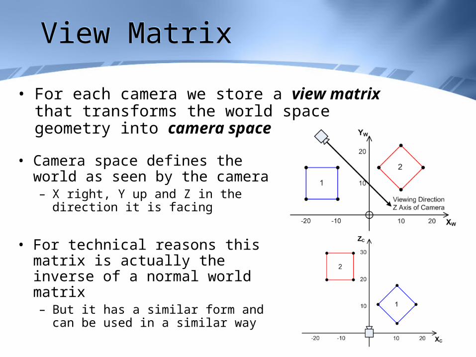
• For each camera we store a view matrix that transforms the world space geometry into camera space
• Camera space defines the world as seen by the camera– X right, Y up and Z in the direction it
is facing
• For technical reasons this matrix is actually the inverse of a normal world matrix– But it has a similar form and can be
used in a similar way
Projection MatrixProjection Matrix
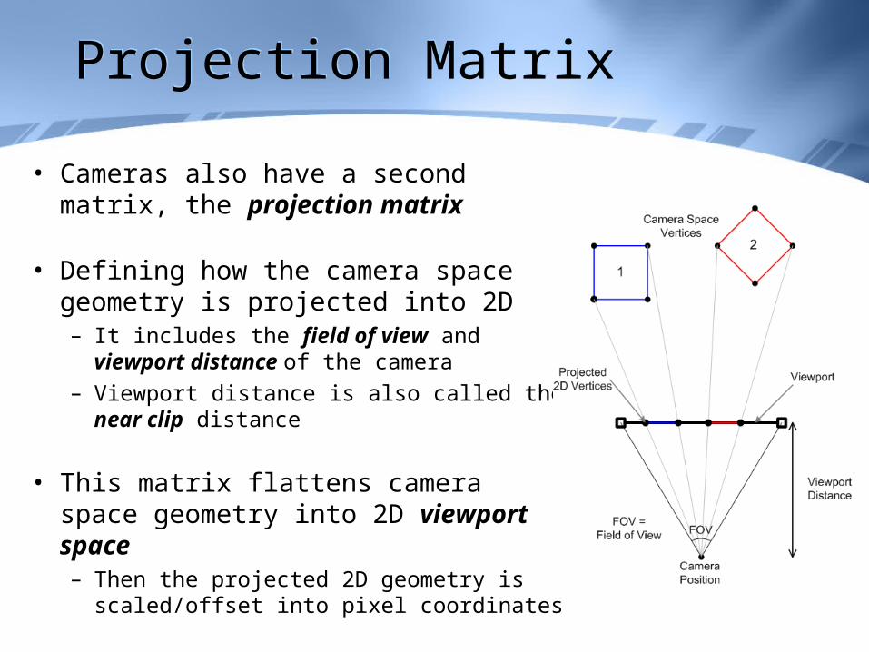
• Cameras also have a second matrix, the projection matrix
• Defining how the camera space geometry is projected into 2D– It includes the field of view and viewport
distance of the camera– Viewport distance is also called the near
clip distance
• This matrix flattens camera space geometry into 2D viewport space– Then the projected 2D geometry is
scaled/offset into pixel coordinates
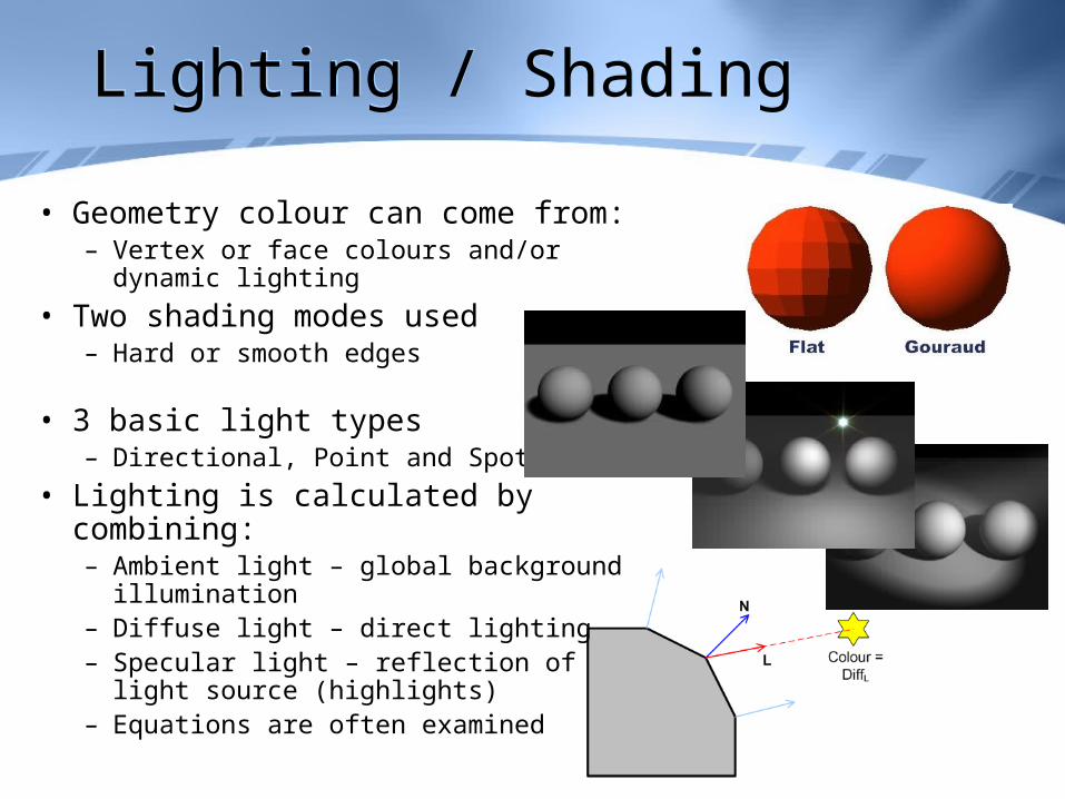
Lighting / ShadingLighting / Shading
• Geometry colour can come from:– Vertex or face colours and/or dynamic
lighting
• Two shading modes used– Hard or smooth edges
• 3 basic light types– Directional, Point and Spot
• Lighting is calculated by combining:– Ambient light – global background
illumination– Diffuse light – direct lighting– Specular light – reflection of light source
(highlights)– Equations are often examined
TexturesTextures
• A texture is a bitmap wrapped around a model• The wrapping is specified by assigning a texture
coordinate (UV) to each vertex in the geometry– This is texture mapping
• The UVs for the texture range from 0-1– UVs outside this range will be wrapped, mirrored, etc. depending on
the texture addressing mode
• Each pixel in the bitmap appears as a square on the geometry called a texel
• Textures and texels can be smoothed using texture filtering and mip-mapping
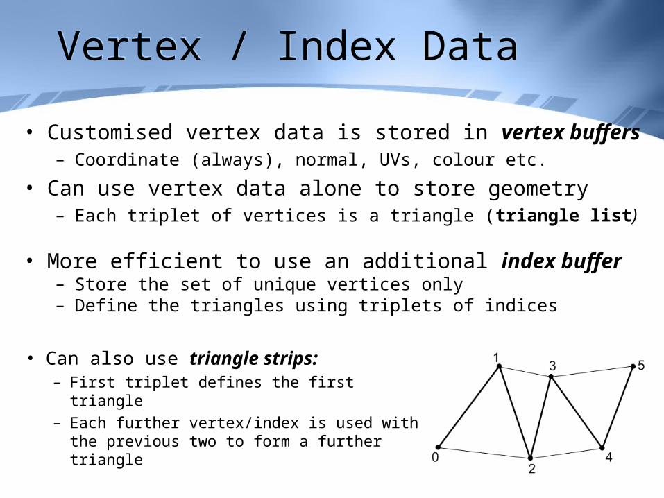
Vertex / Index DataVertex / Index Data
• Customised vertex data is stored in vertex buffers– Coordinate (always), normal, UVs, colour etc.
• Can use vertex data alone to store geometry– Each triplet of vertices is a triangle (triangle list)
• More efficient to use an additional index buffer– Store the set of unique vertices only– Define the triangles using triplets of indices
• Can also use triangle strips:– First triplet defines the first triangle– Each further vertex/index is used with the
previous two to form a further triangle
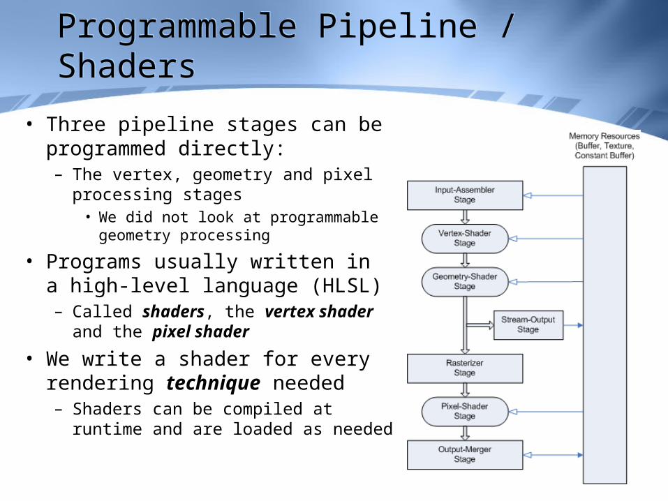
Programmable Pipeline / ShadersProgrammable Pipeline / Shaders
• Three pipeline stages can be programmed directly:– The vertex, geometry and pixel
processing stages• We did not look at programmable
geometry processing
• Programs usually written in a high-level language (HLSL)– Called shaders, the vertex shader
and the pixel shader
• We write a shader for every rendering technique needed– Shaders can be compiled at runtime
and are loaded as needed
Vertex ShadersVertex Shaders
• We define shaders in terms of:– Inputs - from previous stages
– Outputs - to later stages
• Shaders have a “typical ” usage, but are actually very flexible
• Vertex shaders operate on each vertex in the original 3D geometry. Their typical usage is to:– Transform and project the vertex into viewport space
– Perhaps apply animation or lighting to the vertex
• At a minimum, a vertex shader expects vertex coordinates as input, but may have other input too:– Normals, UVs, vertex colours, etc.
• A vertex shader must at the very least output a viewport position for the current vertex, although they often output much more
Pixel ShadersPixel Shaders
• Pixel Shaders operate on each pixel in the final 2D polygons. Their typical usage is to:– Sample (and filter) any textures applied to the polygon– Combine the texture colour with the existing polygon colour (from
lighting and/or geometry colours)
• Input for a pixel shader is usually the output from the vertex shader• After rasterization
• A pixel shader must at least output a final pixel colour to be drawn/blended with the viewport
A Random Image
Advanced ShadersAdvanced Shaders
• Advanced shaders can be used to implement high-quality lighting and rendering techniques
• A key technique is per-pixel lighting– Vertex lighting exhibits problems on large polygons
• Instead, have the vertex shader pass the vertex position and normal on to the pixel shader
• These are interpolated for the pixel shader, which the uses the normal lighting equations on them
• Have covered several other shader techniques:– Specular mapping, normal mapping, parallax mapping, cell shading
Graphics ArchitectureGraphics Architecture
• The basic graphics architecture for all modern PCs and game consoles is similar
• Comprised of a main system and a graphics unit– With one processor each (CPU & GPU)– Fast local RAM for each processor
• Interface between these two systems is often slow
• GPU is a dedicated graphics microprocessor– Much faster than a CPU for graphics related algorithms
• GPU runs at the same time as the CPU– These are concurrent systems
Depth Buffers – Z-BuffersDepth Buffers – Z-Buffers
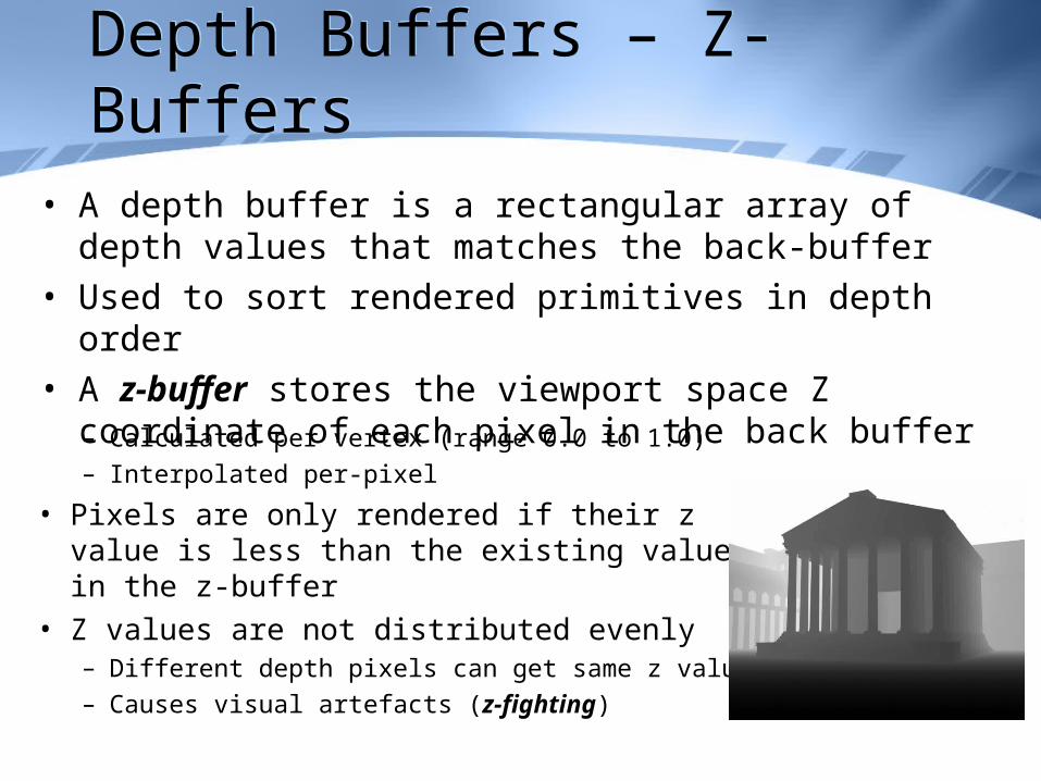
• A depth buffer is a rectangular array of depth values that matches the back-buffer
• Used to sort rendered primitives in depth order• A z-buffer stores the viewport space Z coordinate of each
pixel in the back buffer– Calculated per vertex (range 0.0 to 1.0)– Interpolated per-pixel
• Pixels are only rendered if their z value is less than the existing value in the z-buffer
• Z values are not distributed evenly– Different depth pixels can get same z value– Causes visual artefacts (z-fighting)
Stencil BuffersStencil Buffers
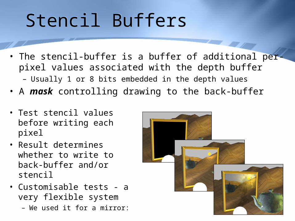
• Test stencil values before writing each pixel
• Result determines whether to write to back-buffer and/or stencil
• Customisable tests - a very flexible system– We used it for a mirror:
• The stencil-buffer is a buffer of additional per-pixel values associated with the depth buffer– Usually 1 or 8 bits embedded in the depth values
• A mask controlling drawing to the back-buffer
Rendering to TexturesRendering to Textures
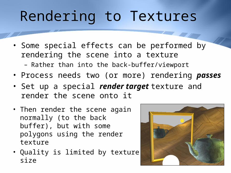
• Some special effects can be performed by rendering the scene into a texture– Rather than into the back-buffer/viewport
• Process needs two (or more) rendering passes • Set up a special render target texture and render the
scene onto it
• Then render the scene again normally (to the back buffer), but with some polygons using the render texture
• Quality is limited by texture size
Shadow TechniquesShadow Techniques
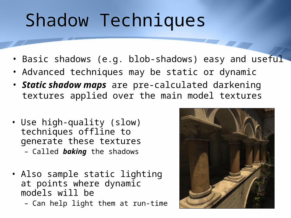
• Basic shadows (e.g. blob-shadows) easy and useful• Advanced techniques may be static or dynamic• Static shadow maps are pre-calculated darkening textures
applied over the main model textures
• Use high-quality (slow) techniques offline to generate these textures– Called baking the shadows
• Also sample static lighting at points where dynamic models will be– Can help light them at run-time
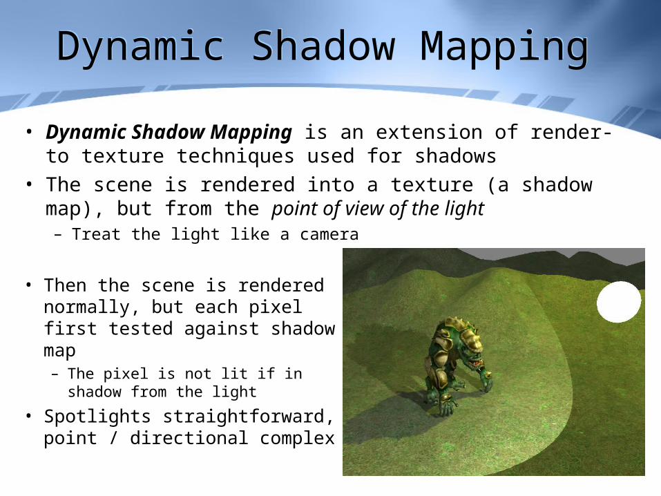
Dynamic Shadow MappingDynamic Shadow Mapping
• Dynamic Shadow Mapping is an extension of render-to texture techniques used for shadows
• The scene is rendered into a texture (a shadow map), but from the point of view of the light– Treat the light like a camera
• Then the scene is rendered normally, but each pixel first tested against shadow map– The pixel is not lit if in shadow
from the light
• Spotlights straightforward, point / directional complex

Rigid Body AnimationRigid Body Animation
• Rigid body animation concerns models made of several distinct parts– We assume that the parts form a hierarchy
• Each part in the hierarchy has a world matrix– Defining its position and orientation - just like a model
• Each part’s matrix is stored relative to its parent– And defines the joint with the parent
• This is called a Matrix or Transform Hierarchy
• Can be rendered using a recursive process• Or the parts can be stored in a depth-first list and
rendered using an iterative process and a stack
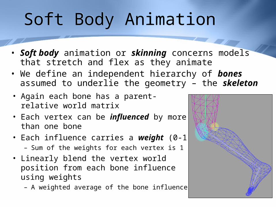
Soft Body AnimationSoft Body Animation
• Soft body animation or skinning concerns models that stretch and flex as they animate
• We define an independent hierarchy of bones assumed to underlie the geometry – the skeleton
• Again each bone has a parent-relative world matrix
• Each vertex can be influenced by more than one bone
• Each influence carries a weight (0-1)– Sum of the weights for each vertex is 1
• Linearly blend the vertex world position from each bone influence using weights– A weighted average of the bone influences
Top Related