


Languages
Pages
Legal

7RRJASI | Volume 2 | Issue 1 | January - March, 2018
Research & Reviews: Journal of Applied Science and Innovations
INTRODUCTIONCold formed light gauge steel products are manufactured by bending a flat steel sheet at room temperature in a way that
will withstand more load than the flat sheet itself. Cold-formed light gauge steel specimens are manufactured by cold rolling. Lightweight gauge steel angle sections and channel sections of a sections and specimens are generally made by folding a flat sheet. Thus, the original strip is converted into two different regions, one of which is corner portion and another region is of a flat portion. Due to the cold forming of the light angle sections and channel sections, the mechanical properties of the steel are modified. These angular sections are used for structural framing in transmission towers, railway wagons steel, beams and low-rise buildings.
LITERATURE SURVEY“Cold Formed light gauge Steel Plain Angle Compression Members” by G. Vani, P.Jayabalan, Jikhil Joseph[1] studied From I
was observed that the load capacity of the section decreases as the ratio b/t increases. For the same relation b/t that increases the length, the load capacity of the section decreases due to the slenderness effect.The analysis of cold formed light gauge steel of general load method analyzes were performed to obtain the load-displacement plot and the final loads. The final load capacity decreases with the increase in the b/t ratio, as well as the length.
“Cold-formed steel angles under axial compression” by G.M.B. Chodraui, Y. Shifferaw, M. Malite, B. W. Schafer[2] The aim of this paper is to examine the stability and strength of Concordically charged cold formed steel angles as determined by Experiment, and Fem model (ABAQUS CAE Version 6.14).
“Improved design rules for fixed cold formed terminations Steel columns subjected to torsional flexion” by Shanmuganathan, Gunalan, and Mahen Mahendran[3]. This paper has presented the details of a research on flexion and Bearing bending behavior of structural steel columns Fixed ends. The current design rules for the capabilities of members of steel columns Based on the same non-dimensional force curve for fixed and fixed end columns. This research has reviewed the accuracy of current design standards
Comparitive Study on Cold Formed Light Gauge Steel Angle Sections and Channel Sections of Compression Members
Deepla N* and Venkat R
Department of Civil engineering, V.R.Siddhartha Engineering College, Vijayawada, Andra pradesh
Research Article
Received date: 12/09/2017Accepted date: 07/01/2018Published date: 08/01/2018
*For Correspondence
Deepla N, Department of Civil engineering, M.Tech,V.R.Siddhartha Engineering College, Vijayawada, Andra pradesh.
E-mail: [email protected]
Keywords: Channel section; Steel, Cold formed light gauge
ABSTRACT
The comparative study on cold formed light gauge steel angle sections and channel sections of compression members using the finite element software by using ABAQUS CAE version 6.14 was used to model the angle & channel specimens. The present study focuses mainly on the investigation of inelastic behavior of a fixed end and the other end is pin-terminated cold-formed light-gauge steel angles and channel sections of compression members using the technique Modern.
For finite element analysis general purpose ABAQUS CAE Version 6.14 software has been used three different nominal section sizes are tested. The cold formed light gauge steel angle sections and channel sections of specimens should be studied for the same b/t ratio such as 25, 25 and 25. The length is varied and the thickness (2 mm) remains constant for angled sections and channel specimens. These specimens are analyzed for different lengths such as 400 mm, 500 mm, and 600 mm. For the same relation b/t that increases the length, the load capacity of the section decreases due to the slenderness effect. The length of a compression member increases then it reduces the load carrying capacity of a member.
8
Research & Reviews: Journal of Applied Science and Innovations
RRJASI | Volume 2 | Issue 2 | January - March, 2018
in AS/NZS 4600 and Specification of North America to determine the capacities of members of cold formed steel Columns using finite element detailed analysis results and an experimental study of Lipped channel columns [4,5].
MATERIAL PROPERTIESLight steel cold rolled steel, essentially hot rolled, which has an additional processing Cold formed light gauge steel is further
processed in the cold reduction mills, where the material is cooled to room temperature (Table 1).
Table 1. Light steel cold rolled steel, essentially hot rolled.
Mechanical properties Hot rolled Cold rolled Tensile strength 67000 Psi 85000 PsiYield strength 45000 Psi 70000 Psi
Brinnels hardness 137 167
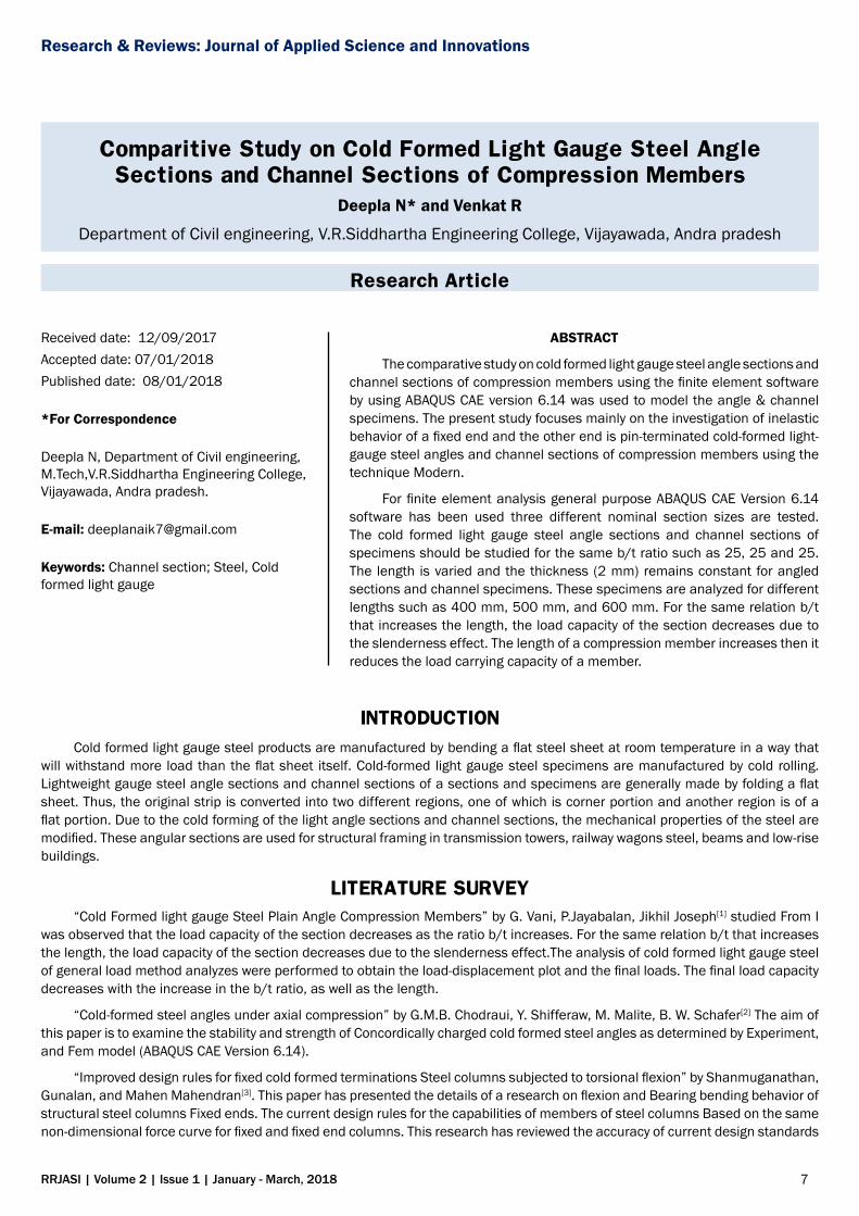
METHODOLOGYThe experimental study has been carried by considering the cold formed light gauge steel angle columns 50 × 50 × 2.0 mm
size [6]. IS 801-1975 provides the distance between the shear centre and centre of gravity of the respective angle and channel sections. Three different lengths are to be tested in hydraulic pressure by using loading frame [7].
To determine the comparative study on cold formed light gauge steel angle and channel specimens of a compression members the load should be applied at shear centre and taking eccentricity from shear centre up to centre of gravity, with varying the length of the columns such as 400 mm, 500 mm and 600 mm (Figure 1).
Figure 1. Angle sections of 400 mm, 500 mm and 600 mm lengths.
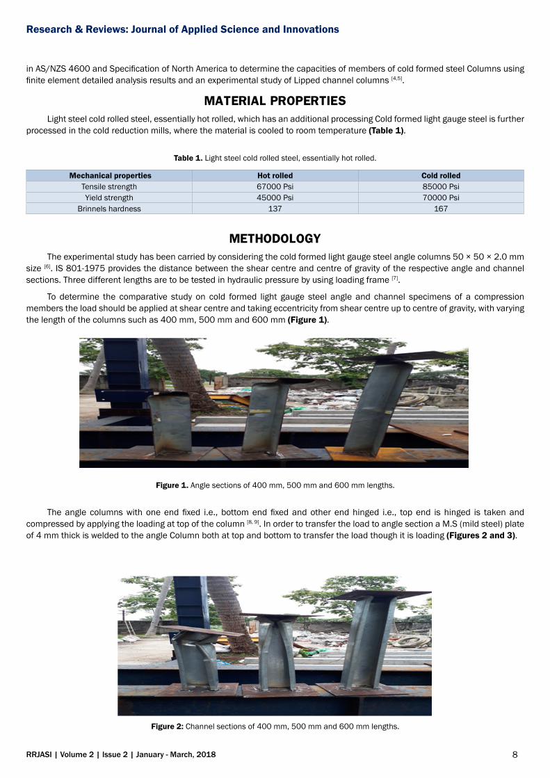
The angle columns with one end fixed i.e., bottom end fixed and other end hinged i.e., top end is hinged is taken and compressed by applying the loading at top of the column [8, 9]. In order to transfer the load to angle section a M.S (mild steel) plate of 4 mm thick is welded to the angle Column both at top and bottom to transfer the load though it is loading (Figures 2 and 3).
Figure 2: Channel sections of 400 mm, 500 mm and 600 mm lengths.
9
Research & Reviews: Journal of Applied Science and Innovations
RRJASI | Volume 2 | Issue 2 | January - March, 2018
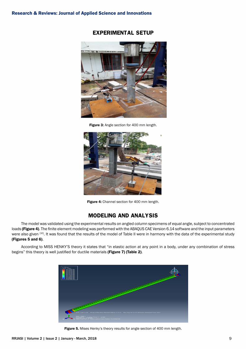
EXPERIMENTAL SETUP
Figure 3: Angle section for 400 mm length.
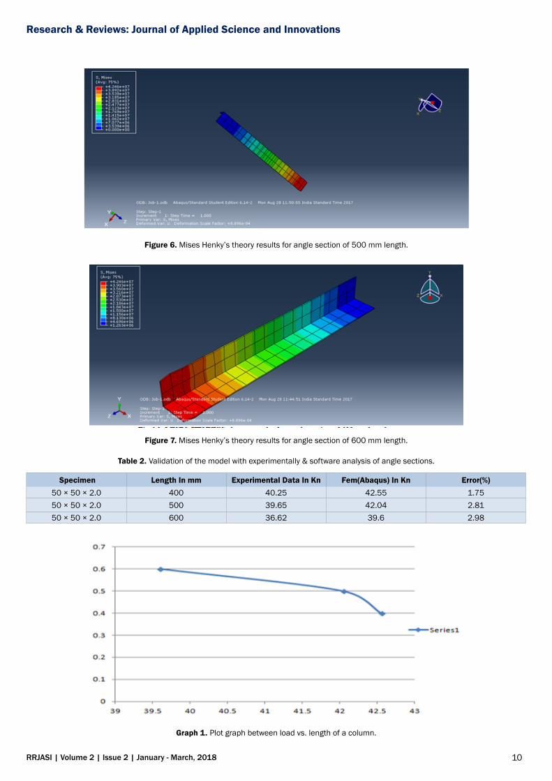
Figure 4: Channel section for 400 mm length.
MODELING AND ANALYSISThe model was validated using the experimental results on angled column specimens of equal angle, subject to concentrated
loads (Figure 4). The finite element modeling was performed with the ABAQUS CAE Version 6.14 software and the input parameters were also given [10]. It was found that the results of the model of Table II were in harmony with the data of the experimental study (Figures 5 and 6).
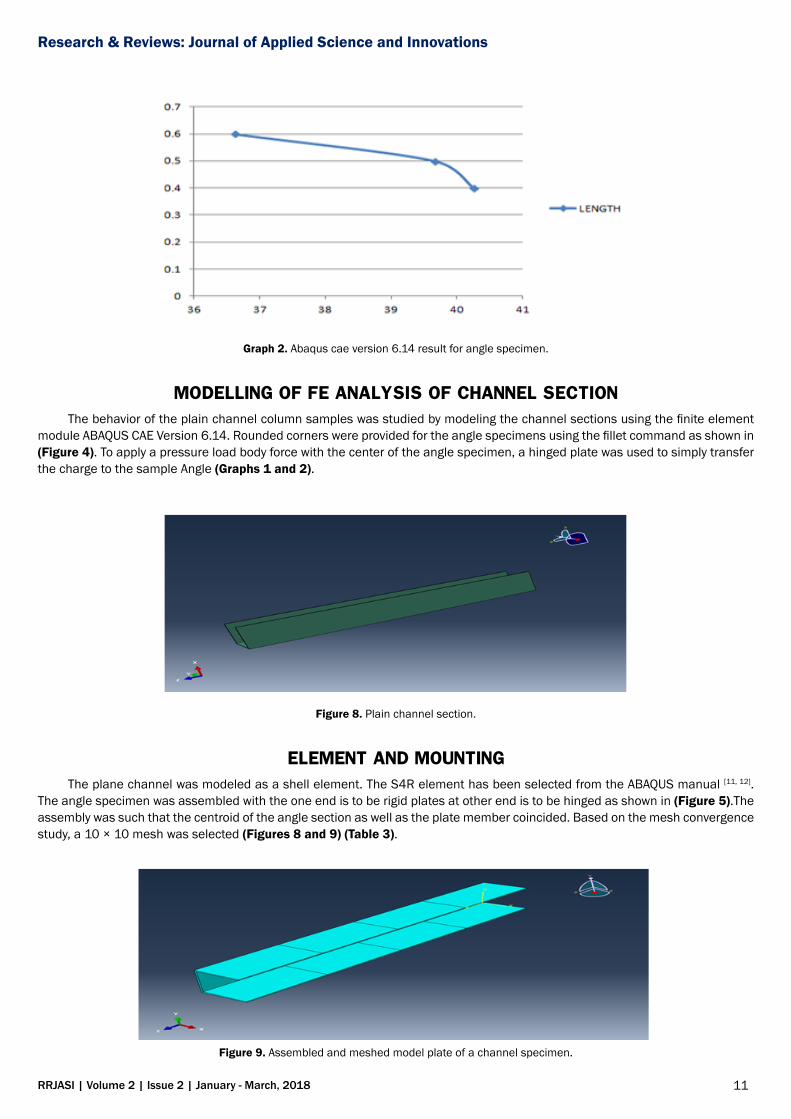
According to MISS HENKY’S theory it states that “in elastic action at any point in a body, under any combination of stress begins” this theory is well justified for ductile materials (Figure 7) (Table 2).
Figure 5. Mises Henky’s theory results for angle section of 400 mm length.
10
Research & Reviews: Journal of Applied Science and Innovations
RRJASI | Volume 2 | Issue 2 | January - March, 2018
Figure 6. Mises Henky’s theory results for angle section of 500 mm length.
Figure 7. Mises Henky’s theory results for angle section of 600 mm length.
Table 2. Validation of the model with experimentally & software analysis of angle sections.
Specimen Length In mm Experimental Data In Kn Fem(Abaqus) In Kn Error(%)50 × 50 × 2.0 400 40.25 42.55 1.7550 × 50 × 2.0 500 39.65 42.04 2.8150 × 50 × 2.0 600 36.62 39.6 2.98
Graph 1. Plot graph between load vs. length of a column.
11
Research & Reviews: Journal of Applied Science and Innovations
RRJASI | Volume 2 | Issue 2 | January - March, 2018
Graph 2. Abaqus cae version 6.14 result for angle specimen.
MODELLING OF FE ANALYSIS OF CHANNEL SECTIONThe behavior of the plain channel column samples was studied by modeling the channel sections using the finite element
module ABAQUS CAE Version 6.14. Rounded corners were provided for the angle specimens using the fillet command as shown in (Figure 4). To apply a pressure load body force with the center of the angle specimen, a hinged plate was used to simply transfer the charge to the sample Angle (Graphs 1 and 2).
Figure 8. Plain channel section.
ELEMENT AND MOUNTINGThe plane channel was modeled as a shell element. The S4R element has been selected from the ABAQUS manual [11, 12].
The angle specimen was assembled with the one end is to be rigid plates at other end is to be hinged as shown in (Figure 5).The assembly was such that the centroid of the angle section as well as the plate member coincided. Based on the mesh convergence study, a 10 × 10 mesh was selected (Figures 8 and 9) (Table 3).
Figure 9. Assembled and meshed model plate of a channel specimen.
12
Research & Reviews: Journal of Applied Science and Innovations
RRJASI | Volume 2 | Issue 2 | January - March, 2018
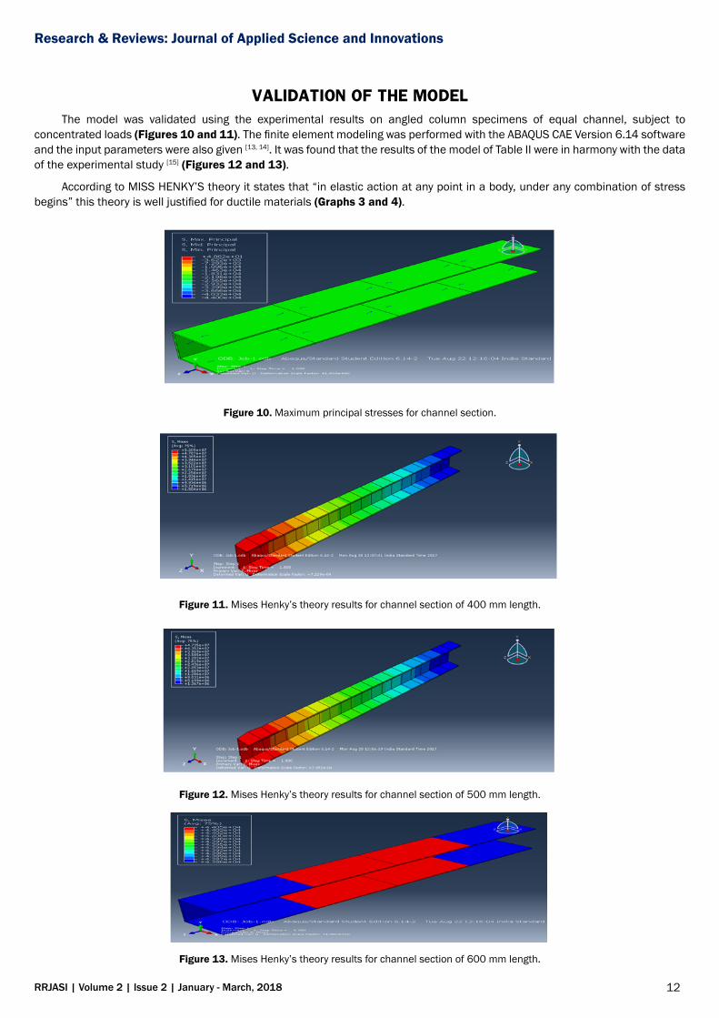
VALIDATION OF THE MODELThe model was validated using the experimental results on angled column specimens of equal channel, subject to
concentrated loads (Figures 10 and 11). The finite element modeling was performed with the ABAQUS CAE Version 6.14 software and the input parameters were also given [13, 14]. It was found that the results of the model of Table II were in harmony with the data of the experimental study [15] (Figures 12 and 13).
According to MISS HENKY’S theory it states that “in elastic action at any point in a body, under any combination of stress begins” this theory is well justified for ductile materials (Graphs 3 and 4).
Figure 10. Maximum principal stresses for channel section.
Figure 11. Mises Henky’s theory results for channel section of 400 mm length.
Figure 12. Mises Henky’s theory results for channel section of 500 mm length.
Figure 13. Mises Henky’s theory results for channel section of 600 mm length.
13
Research & Reviews: Journal of Applied Science and Innovations
RRJASI | Volume 2 | Issue 2 | January - March, 2018
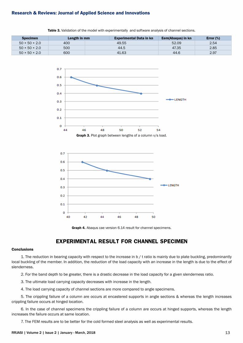
Table 3. Validation of the model with experimentally and software analysis of channel sections.
Specimen Length in mm Experimental Data in kn Eem(Abaqus) in kn Error (%)50 × 50 × 2.0 400 49.55 52.09 2.5450 × 50 × 2.0 500 44.5 47.35 2.8550 × 50 × 2.0 600 41.63 44.6 2.97
Graph 3. Plot graph between lengths of a column v/s load.
Graph 4. Abaqus cae version 6.14 result for channel specimens.
EXPERIMENTAL RESULT FOR CHANNEL SPECIMENConclusions
1. The reduction in bearing capacity with respect to the increase in b / t ratio is mainly due to plate buckling, predominantly local buckling of the member. In addition, the reduction of the load capacity with an increase in the length is due to the effect of slenderness.
2. For the band depth to be greater, there is a drastic decrease in the load capacity for a given slenderness ratio.
3. The ultimate load carrying capacity decreases with increase in the length.
4. The load carrying capacity of channel sections are more compared to angle specimens.
5. The crippling failure of a column are occurs at encastered supports in angle sections & whereas the length increases crippling failure occurs at hinged location.
6. In the case of channel specimens the crippling failure of a column are occurs at hinged supports, whereas the length increases the failure occurs at same location.
7. The FEM results are to be better for the cold formed steel analysis as well as experimental results.
14
Research & Reviews: Journal of Applied Science and Innovations
RRJASI | Volume 2 | Issue 2 | January - March, 2018
REFERENCES1. Alexander C. Principles of Structural Stability Theory. Prentice-Hall Inc. 1974.
2. Ben Y. Trials and design of cold-formed, fixed-angle steel columns. J Struct Engine. 2004;131:187-207.
3. Ben Y. Experimental investigation of concentrically loaded compression members in cold formed steel latex angle. J Struct Engine. 2005;131:1-10.
4. Ben Y. Research on cold-formed steel columns, thin-walled structures. 2008;46:731-740.
5. Design of uneven angle compression members made of cold formed steel.
6. Ben Y, Chen J. Column tests of angle sections with non-sy mm etrical cold formed steel lips, J Constru Stel resea. 2008.
7. Ben Y, Kim JR. Behavior of sy mm etrical columns isolated in cold. Thi Wall Structu. 1999;33:83-102.
8. Ben Y, Wing ML. Tests of cold-formed high strength stainless steel compression elements thin-walled structures. 2006;44:224-234
9. Schafer W, Li Zand, Moen CD. Computational modeling of cold formed steel, thin-walled structures Christopher. Jour Constru Stee Rese.2010;47:193-210.
10. Moen D, Takeru I, Schafer BW. Prediction of stresses and residual stresses in cold-formed steel elements, thin-walled structures. J Advan Scie Engin Res.2008;2:252-264.
11. Popovic GJ, Hancock, KJR Rasmussen. Compression tests on cold formed angles loaded parallel to one leg. J Struct Engine.2001.
12. Popov GJ, Hancock, Rasmussen KJR. 1999.Tests of axial compression of cold formed angles, J Struct Engine. 2010.
13. Ehab E, Ben Y. 2005 Behavior of Cold-formed Steel Plain Angle Columns. J Struct Engine.2005;131.
14. Stephen T, James MG. Elastic Stability Theory, 2nd Edtn, Tata McGraw-Hill. 2010.
15. The limited finite band method for thin-wall members with general boundary conditions. J Enginee Mech.
Top Related