


Languages
Pages
Legal

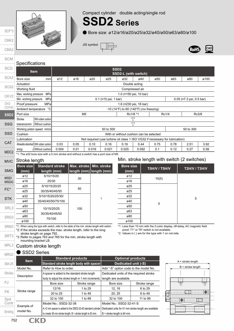
Compact cylinder double acting/single rod
SSD2 Series Bore size: ø12/ø16/ø20/ø25/ø32/ø40/ø50/ø63/ø80/ø100
JIS symbol
Specifications
*1: The ø32 bore size with a 5 mm stroke and without a switch has a port size of M5.
Item SSD2SSD2-L (with switch)
Bore size mm ø12 ø16 ø20 ø25 ø32 ø40 ø50 ø63 ø80 ø100Actuation Double actingWorking fluid Compressed airMax. working pressure MPa 1.0 (≈150 psi, 10 bar)Min. working pressure MPa 0.1 (≈15 psi, 1 bar) 0.05 (≈7.3 psi, 0.5 bar)Proof pressure MPa 1.6 (≈230 psi, 16 bar)Ambient temperature °C -10 (14°F) to 60 (140°F) (no freezing)Port size M5 Rc1/8 *1 Rc1/4 Rc3/8Stroke tolerance mm
With rubber cushion +2.00
Without cushion +1.00
Working piston speed mm/s 50 to 500 50 to 300Cushion With or without cushion can be selectedLubrication Not required (use turbine oil class 1 ISO VG32 if necessary for lubrication)Allowable absorbed energy J
With rubber cushion 0.03 0.05 0.10 0.16 0.16 0.44 0.75 0.78 2.51 3.92Without cushion 0.004 0.01 0.016 0.021 0.025 0.092 0.1 0.12 0.27 0.56
Custom stroke length SSD2 Series
ItemStandard products Optional products
Standard stroke length body with spacer Dedicated unit (-S)Model No. Refer to How to order. Add “-S” option code to the model No.
DescriptionA spacer is added to the standard stroke length body to adjust the stroke length in 1 mm increments.
Dedicated units of the required stroke length are available.
Stroke range
Bore size Stroke range Bore size Stroke range12/16 1 to 29 12, 16 6 to 29
20 to 25 1 to 49 20, 25 6 to 4932 to 100 1 to 99 32 to 100 11 to 99
Example of model No.
Model No.: SSD2-32-38A +2 mm spacer is added to the SSD2-32-40 standard cylinder to create 38 mm stroke length. B + stroke length is 63 mm.
Model No.: SSD2-32-41-SDedicated units for 41 mm stroke length are available.B + stroke length is 64 mm.
Stroke length
*1 : When using the type with switch, refer to the table of the min. stroke length with switch.*2 : If the stroke exceeds the max. stroke length, refer to the long
stroke length on page 792.*3 : Refer to pages 763 and 765 for the min. stroke length with
mounting bracket LB.
Bore size (mm)
Standard stroke length (mm)
Max. stroke length (mm)
Min. stroke length (mm)
ø12 5/10/15/2025/30
30
1
ø16ø20 5/10/15/20/25
30/35/40/45/5050
ø25ø32 5/10/15/20/25/30/
35/40/45/50/75/100
100
ø40ø50
10/15/20/2530/35/40/45/50
75/100
ø63ø80ø100
Min. stroke length with switch (2 switches)
*1 : Less than 10 mm with the 2-color display, off-delay, AC magnetic field proof, T1* or T8* switch is not available.
*2 : Values in ( ) are for the type with 1 on rod side.
Bore size (mm)
T0H/V / T5H/V T2H/V / T3H/V
ø1210(5)
5
ø16ø20
5
ø25ø32ø40ø50ø63ø80ø100
A + stroke length
B + stroke length
SCP*3
CMK2
CMA2
SCM
SCG
SCA2
SCS2
CKV2
CAV2/COVP/N2
SSD2
SSG
SSD
CAT
MDC2
MVC
SMG
MSD/MSDG
FC*
STK
SRL3
SRG3
SRM3
SRT3
MRL2
MRG2
SM‑25
ShkAbs
FJ
FK
SpdContr
Ending
752

SSD2 SeriesSpecifications
*1 : Refer to Ending Page 1 for detailed switch specifications and dimensions. *2 : Switches other than the above models, such as switches with connectors, are also available. Refer to Ending Page 1. *3 : The max. load current is 20 mA at 25°C. The current is lower than 20 mA if the operating ambient temperature around the switch is higher than 25˚C.
(5 to 10 mA at 60°C) *4 : Switch for AC magnetic field (T2YD/T2YDT) cannot be used in DC magnetic field. *5 : The F type switch uses a bend-resistant lead wire.
Switch specifications (T switch) 1-color/2-color display/for AC magnetic field proof
ItemProximity 2-wire Proximity 2-wire Proximity 3-wire Reed 2-wire Proximity 2-wire
T1H/T1VT2H/T2V/
T2JH/T2JVT2YH/T2YV
T2WH/T2WV
T3H/T3V
T3PH/T3PV
T3YH/T3YV
T3WH/T3WV
T0H/T0V T5H/T5V T8H/T8VT2YD(*4)T2YDT
Applications For programmable controller, relay, compact solenoid valve
Dedicated for programmable controller
For programmable controller, relay
For programmable controller, relay
For programmable controller, relay, IC circuit (no indicator lamp), serial connection
For programmable controller, relay
For programmable controller
Output method - NPN output PNP output NPN output NPN output -Pwr. supp. V. - 10 to 28 VDC -Load voltage 85 to 265 VAC 10 to 30 VDC 24 VDC ±10% 30 VDC or less 12/24 VDC 100/110 VAC 5/12/24 VDC 100/110 VAC 12/24 VDC 110 VAC 220 VAC 24 VDC ±10%Load current 5 to 100 mA 5 to 20 mA (*3) 100mA or less 50mA or less 5 to 50 mA 7 to 20 mA 50 mA or less 20 mA or less 5 to 50 mA 7 to 20 mA 7 to 10 mA 5 to 20 mA
Indicator lamp
LED(Lit when ON)
LED (Lit when ON)
Red/green LED
(Lit when ON)
Red/green LED
(Lit when ON)
LED (Lit when ON)
YellowLED
(Lit when ON)
Red/green LED
(Lit when ON)
Red/green LED
(Lit when ON)
LED(Lit when ON)
Without indicator lamp
LED(Lit when ON)
Red/green LED
(Lit when ON)
Leakage current ≤ 1 mA at 100 VAC, ≤ 2 mA at 200 VAC 1 mA or less 10 μA or less 0 mA 1 mA or less
Weight g
1 m:33
3 m:87
5 m:142
1 m:18
3 m:49
5 m:80
1 m:33
3 m:87
5 m:142
1 m:18
3 m:49
5 m:80
1 m:18
3 m:49
5 m:80
1 m:33
3 m:87
5 m:142
1 m:18
3 m:49
5 m:80
1 m:18 3 m:49 5 m:80
1 m:33
3 m:87
5 m:142
1 m:61
3 m:166
5 m:272
Stroke length (mm) 5 10 15 20 25 30 35 40 45 50 75 100Bore size (mm) No switch Switch No switch Switch No switch Switch No switch Switch No switch Switch No switch Switch No switch Switch No switch Switch No switch Switch No switch Switch No switch Switch No switch Switch
ø12 36 86 44 86 53 95 61 103 70 112 72 114 - - - - - - - - - - - -ø16 48 104 59 104 69 114 80 125 91 136 102 147 - - - - - - - - - - - -ø20 63 118 75 150 88 163 101 176 113 188 126 201 139 214 152 227 165 240 203 278 - - - -ø25 87 178 102 193 118 209 134 225 150 241 165 256 181 272 197 288 213 304 228 319 - - - -ø32 122 236 144 258 166 280 188 302 209 323 231 345 253 367 275 389 297 411 318 432 494 542 604 652ø40 183 326 210 353 236 379 263 406 290 433 316 459 342 485 369 512 395 538 472 565 646 695 776 825ø50 - - 341 535 383 577 425 619 467 661 510 704 552 746 594 788 636 830 678 872 1025 1082 1235 1292ø63 - - 507 786 562 841 617 896 672 951 727 1006 782 1061 838 1117 893 1172 948 1227 1438 1502 1713 1777ø80 - - 928 1341 1015 1428 1101 1514 1188 1601 1274 1687 1361 1774 1448 1861 1535 1948 1621 2034 2401 2467 2833 2899
ø100 - - 1433 2000 1547 2114 1660 2227 1774 2341 1888 2455 2002 2569 2115 2682 2229 2796 2343 2910 3406 3478 3973 4045
Cylinder weight table (the weight of the switches is when there are 2 cylinder switches.)
(Unit: N)
(Unit: g)
Switch specifications (F switch) 1-color/2-color display
ItemProximity 2-wire Proximity 3-wire Proximity 2-wire Proximity 3-wire
F2S F3S F2H/F2V F2YH/F2YV F3H/F3VF3PH/F3PV
(made to order)F3YH/F3YV
Applications Dedicated for programmable controller
For programmable controller, relay
Dedicated for programmable controller
For programmable controller, relay
Output method - NPN output - NPN output PNP output NPN outputPower supply voltage - 10 to 28 VDC - 10 to 28 VDC 4.5 to 28 VDC 10 to 28 VDCLoad voltage 10 to 30 VDC 30 VDC or less 10 to 30 VDC 24 VDC ±10% 30 VDC or lessLoad current 5 to 20 mA 50 mA or less 5 to 20 mA 50 mA or less
Indicator lamp LED(Lit when ON)
Yellow LED(Lit when ON)
Red/greenLED
(Lit when ON)
Yellow LED(Lit when ON)
Red/greenLED
(Lit when ON)Leakage current 1mA or less 10 μA or less 1 mA or less 10 μA or lessWeight g 1 m:10 3 m:29
Theoretical thrust tableBore size
(mm)Operating direction
Working pressure MPa0.05 0.1 0.15 0.2 0.3 0.4 0.5 0.6 0.7 0.8 0.9 1.0
ø12Push - 11.3 17.0 22.6 33.9 45.2 56.5 67.9 79.2 90.5 1.02×10² 1.13×10²
Pull - 8.48 12.7 17.0 25.4 33.9 42.4 50.9 59.4 67.9 76.3 84.8
ø16Push - 20.1 30.2 40.2 60.3 80.4 1.01×10² 1.21×10² 1.41×10² 1.61×10² 1.81×10² 2.01×10²
Pull - 15.1 22.6 30.2 45.2 60.3 75.4 90.5 1.06×10² 1.21×10² 1.36×10² 1.51×10²
ø20Push - 31.4 47.1 62.8 94.2 1.26×10² 1.57×10² 1.88×10² 2.20×10² 2.51×10² 2.83×10² 3.14×10²
Pull - 23.6 35.3 47.1 70.7 94.2 1.18×10² 1.41×10² 1.65×10² 1.88×10² 2.12×10² 2.36×10²
ø25Push - 49.1 73.6 98.2 1.47×10² 1.96×10² 2.45×10² 2.95×10² 3.44×10² 3.93×10² 4.42×10² 4.91×10²
Pull - 37.8 56.7 75.6 1.13×10² 1.51×10² 1.89×10² 2.27×10² 2.64×10² 3.02×10² 3.40×10² 3.78×10²
ø32Push - 80.4 1.21×10² 1.61×10² 2.41×10² 3.22×10² 4.02×10² 4.83×10² 5.63×10² 6.43×10² 7.24×10² 8.04×10²
Pull - 60.3 90.5 1.21×10² 1.81×10² 2.41×10² 3.02×10² 3.62×10² 4.22×10² 4.83×10² 5.43×10² 6.03×10²
ø40Push - 1.26×10² 1.88×10² 2.51×10² 3.77×10² 5.03×10² 6.28×10² 7.54×10² 8.80×10² 1.01×10³ 1.13×10³ 1.26×10³
Pull - 1.06×10² 1.58×10² 2.11×10² 3.17×10² 4.22×10² 5.28×10² 6.33×10² 7.39×10² 8.44×10² 9.50×10² 1.06×10³
ø50Push - 1.96×10² 2.95×10² 3.93×10² 5.89×10² 7.85×10² 9.82×10² 1.18×10³ 1.37×10³ 1.57×10³ 1.77×10³ 1.96×10³
Pull - 1.65×10² 2.47×10² 3.30×10² 4.95×10² 6.60×10² 8.25×10² 9.90×10² 1.15×10³ 1.32×10³ 1.48×10³ 1.65×10³
ø63Push 1.56×10² 3.12×10² 4.68×10² 6.23×10² 9.35×10² 1.25×10³ 1.56×10³ 1.87×10³ 2.18×10³ 2.49×10³ 2.81×10³ 3.12×10³
Pull 1.40×10² 2.80×10² 4.20×10² 5.61×10² 8.41×10² 1.12×10³ 1.40×10³ 1.68×10³ 1.96×10³ 2.24×10³ 2.52×10³ 2.80×10³
ø80Push 2.51×10² 5.03×10² 7.54×10² 1.01×10³ 1.51×10³ 2.01×10³ 2.51×10³ 3.02×10³ 3.52×10³ 4.02×10³ 4.52×10³ 5.03×10³
Pull 2.27×10² 4.54×10² 6.80×10² 9.07×10² 1.36×10³ 1.81×10³ 2.27×10³ 2.72×10³ 3.17×10³ 3.63×10³ 4.08×10³ 4.54×10³
ø100Push 3.93×10² 7.85×10² 1.18×10³ 1.57×10³ 2.36×10³ 3.14×10³ 3.93×10³ 4.71×10³ 5.50×10³ 6.28×10³ 7.07×10³ 7.85×10³
Pull 3.57×10² 7.15×10² 1.07×10³ 1.43×10³ 2.14×10³ 2.86×10³ 3.57×10³ 4.29×10³ 5.00×10³ 5.72×10³ 6.43×10³ 7.15×103
SCP*3
CMK2
CMA2
SCM
SCG
SCA2
SCS2
CKV2
CAV2/COVP/N2
SSD2
SSG
SSD
CAT
MDC2
MVC
SMG
MSD/MSDG
FC*
STK
SRL3
SRG3
SRM3
SRT3
MRL2
MRG2
SM‑25
ShkAbs
FJ
FK
SpdContr
Ending
753

SSD2 Series
Model No.A
Accessory *7
J
Option *4
H
Switch quantityG
*1*2*3*8*9
Switch model No.F
Bore sizeB
Stroke lengthE
CushionD
With switch (built-in magnet for switch)
12 LB IN5SSD2
12 R10 IN
Precautions for model No. selection*1 : The T2YD* switch cannot be mounted on the ø12 and ø16 bore sizes.*2 : The T8* switch cannot be mounted on the ø12 to ø32 bore sizes.*3 : The F type switch can only be mounted on the piping
port surface of bore sizes ø20 and ø25.*4 : Piston rod of ø12 to ø25 is stainless steel as standard.
C type snap ring is stainless steel instead of steel. The rod end male thread nut is stainless steel.*5 : The mounting bracket is included at shipment.*6 : The projection dimension of piston rod WF when LB or FA is
selected is different from that of the standard. Refer to the dimensions on pages 761, 763, 765 and 766. The number of the specified protruding dimension will be added at the end of the model No. printed on the metal plate on the body.
*7 : “I” and “Y” cannot be selected together.*8 : The F type switch with L type lead wire on ø20 models
cannot be selected on stroke lengths of 15 mm or under.*9 : Switches are shipped with the product. Contact CKD if
assembling before shipment is necessary.*10 : Refer to pages 750 and 751 for combinations of
variations/options.*11 : F type switch cannot be selected.
[Example of model No.]SSD2-L-12-10-T0H-R-N-LB-IModel: Compact cylinder, standardB Bore size : ø12 mmC Port thread : Rc threadD Cushion : No cushionE Stroke length : 10mmF Switch model No. : Reed switch T0H, lead wire length 1 mG Switch quantity : 1 on rod sideH Option : Rod end male threadI Mounting bracket : Axial footJ Accessory : Rod eye
How to orderWithout switch (without magnet for switch)
Code DescriptionModel No.SSD2 Double acting/single rod
SSD2-L Double acting/single rod/with switch
Bore size (mm)12 ø1216 ø1620 ø2025 ø2532 ø3240 ø4050 ø5063 ø6380 ø80
100 ø100
Port threadBlank Rc thread
NN NPT thread (ø32 and over) (made-to-order product)GN G thread (ø32 and over) (made-to-order product)
CushionBlank Without cushion
D With rubber cushion
Stroke length (mm)
Refer to the stroke length table on the following page.
* Lead wire lengthBlank 1 m (standard)
3 3 m (option)5 5 m (option) *11
Switch quantityR 1 on rod sideH 1 on head sideD 2
OptionBore size (mm) 12 16 20 25 32 40 50 63 80 100
Blank Rod end female thread N Rod end male thread P6 Copper and PTFE free specifications Supported as standard
M *4 Piston rod material (stainless steel) S Dedicated unit for custom stroke length
P4 Specifications for rechargeable battery
P40
Mounting bracketBlank Without mounting bracket
LB Axial footCB Clevis bracket (pin and snap ring included)FA Rod side flangeFB Head side flange
Accessory (available when rod end male thread “N” is selected)I Rod eyeY Rod clevis (pin and snap ring included)
B
A
D
I
J
H
G
E
C
SSD2-L T0H LB
Switch model No.Axial
lead wireRadial lead
wire Conta
ct Voltage Display Lead wire
Bore sizeAC DC 12 16 20 25 32 40 50 63 80 100
- F2S*
Pro
xim
ity
1-color display
2-wire - F3S* 3-wire
F2H* F2V* 2-wire F3H* F3V* 3-wire
F3PH* F3PV* 1 color display (PNP output) (custom) 3-wire F2YH* F2YV*
2-color display2-wire
F3YH* F3YV* 3-wire T0H* T0V*
Ree
d 1-color display2-wire
T5H* T5V* Without indicator lamp T8H* T8V* 1-color display T1H* T1V*
Pro
xim
ity
1-color display
2-wire
T2H* T2V* T3H* T3V*
3-wire
T3PH* T3PV* 1-color display (PNP output) T2WH* T2WV*
2-color display2-wire
T2YH* T2YV* T3WH* T3WV*
3-wire
T3YH* T3YV* T2YD* - 2-color display
for AC magnetic field 2-wire
T2YDT* - T2JH* T2JV* 1-color display off-delay 2-wire
F
I Mounting bracket *5*6
C Port thread
SCP*3
CMK2
CMA2
SCM
SCG
SCA2
SCS2
CKV2
CAV2/COVP/N2
SSD2
SSG
SSD
CAT
MDC2
MVC
SMG
MSD/MSDG
FC*
STK
SRL3
SRG3
SRM3
SRT3
MRL2
MRG2
SM‑25
ShkAbs
FJ
FK
SpdContr
Ending
754

Stroke length (mm)Applicable bore size
12 16 20 25 32 40 50 63 80 100
Sta
ndar
d st
roke
leng
th
5 10 15 20 25 30 35 40 45 50 75 100
Min. stroke length (mm) *1 1Max. stroke length (mm) 30 50 100Custom stroke length *2 In 1 mm increments
*1 : Less than 5 mm for 1-color display switch and less than 10 mm for the 2-color display, off-delay, AC magnetic field proof, T1* or T8* switch are not available.
Refer to page 752 for the min. stroke length with switch.*2 : The total length when using a custom stroke length is the same as that when using the next longer standard
stroke length.*3 : Refer to pages 763 and 765 for the min. stroke length with mounting bracket LB.
Bore size (mm)ø12 ø16 ø20 ø25 ø32 ø40 ø50
Mounting bracketFoot (LB) SSD2-LB-12 SSD2-LB-16 SSD2-LB-20 SSD2-LB-25 SSD2-LB-32 SSD2-LB-40 SSD2-LB-50Flange (FA/FB) SSD2-FA-12 SSD2-FA-16 SSD2-FA-20 SSD2-FA-25 SSD2-FA-32 SSD2-FA-40 SSD2-FA-50Clevis bracket (CB) SSD2-CB-12 SSD2-CB-16 SSD2-CB-20 SSD2-CB-25 SSD2-CB-32 SSD2-CB-40 SSD2-CB-50
Bore size (mm)ø63 ø80 ø100
Mounting bracketFoot (LB) SSD2-LB-63 SSD2-LB-80 SSD2-LB-100Flange (FA/FB) SSD2-FA-63 SSD2-FA-80 SSD2-FA-100Clevis bracket (CB) SSD2-CB-63 SSD2-CB-80 SSD2-CB-100
SSD2 SeriesHow to order
How to order switch
Switch model No. (Item F on page 754)
SW
*1: The foot mounting bracket is provided as 2 pcs./set.
[Stroke length table]
How to order mounting bracket
SSD2-…………- Design compatible with rechargeable battery manufacturing process
Specifications for rechargeable battery (catalog No. CC-1226A)
P4*
T0H
SCP*3
CMK2
CMA2
SCM
SCG
SCA2
SCS2
CKV2
CAV2/COVP/N2
SSD2
SSG
SSD
CAT
MDC2
MVC
SMG
MSD/MSDG
FC*
STK
SRL3
SRG3
SRM3
SRT3
MRL2
MRG2
SM‑25
ShkAbs
FJ
FK
SpdContr
Ending
755

Internal structure and parts list (ø12 to 50) (no cushion) SSD2-L-12 to 25 (double acting/with switch)
SSD2 Series
SSD2-L-32 to 50 (double acting/with switch)
SSD2-12 to 25 (double acting) SSD2-32 to 50 (double acting)
No. Part name Material Remarks No. Part name Material Remarks
1 Piston rod ø12 to ø25: Stainless steel ø32 to ø50: Steel
ø16 to ø50:Industrial chrome plating 7 Spacer Aluminum alloy ø12 to ø32: Chromate
2 C type snap ring Steel Zinc phosphate 8 Magnet Plastic
3 Rod metal Special aluminum Alumite 9 Piston Aluminum alloy Chromate
4 Rod metal gasket Nitrile rubber 10 Piston packing Nitrile rubber
5 Body Aluminum alloy Hard alumite11 Cover ø12 to ø25: Stainless steel
ø32 to ø50: Aluminum alloy ø32 to ø50: Alumite6 Rod packing Nitrile rubber
Bore size (mm) Kit No. Repair parts No.ø12 SSD2-12K
4 6 10
ø16 SSD2-16Kø20 SSD2-20Kø25 SSD2-25Kø32 SSD2-32Kø40 SSD2-40Kø50 SSD2-50K
Repair parts list
1 2 3 4 5 6 7 8 10 9 11 1 2 3 4 5 6 7 8 10 9 11
1 2 3 4 5 6 9 10 11 1 2 3 4 5 6 9 10 11
SCP*3
CMK2
CMA2
SCM
SCG
SCA2
SCS2
CKV2
CAV2/COVP/N2
SSD2
SSG
SSD
CAT
MDC2
MVC
SMG
MSD/MSDG
FC*
STK
SRL3
SRG3
SRM3
SRT3
MRL2
MRG2
SM‑25
ShkAbs
FJ
FK
SpdContr
Ending
756

SSD2 SeriesInternal structure and parts list
Internal structure and parts list (ø63 to 100) (no cushion) SSD2-L-63 to 100 (double acting/with switch)
SSD2-63 to 100 (double acting)
No. Part name Material Remarks No. Part name Material Remarks1 Piston rod Steel Industrial chrome plating 7 Spacer Aluminum alloy
2 C type snap ring Steel Zinc phosphate 8 Magnet Plastic
3 Rod metal Aluminum alloy Chromate 9 Piston Aluminum alloy Chromate
4 Rod metal gasket Nitrile rubber 10 Piston packing Nitrile rubber
5 Body Aluminum alloy Hard alumite 11 Cover Aluminum alloy Alumite
6 Rod packing Nitrile rubber 12 Bush Oiles drymet *1
Bore size (mm) Kit No. Repair parts No.ø63 SSD2-63K
4 6 10ø80 SSD2-80Kø100 SSD2-100K
Repair parts list
*1: Material is steel for copper and PTFE free specifications.
6 21 3 4 12 5 7 8 10 9 11
1 6 2 3 4 12 5 9 10 11
SCP*3
CMK2
CMA2
SCM
SCG
SCA2
SCS2
CKV2
CAV2/COVP/N2
SSD2
SSG
SSD
CAT
MDC2
MVC
SMG
MSD/MSDG
FC*
STK
SRL3
SRG3
SRM3
SRT3
MRL2
MRG2
SM‑25
ShkAbs
FJ
FK
SpdContr
Ending
757

SSD2 Series
Internal structure and parts list (ø12 to 50) (with rubber cushion) SSD2-L-12D to 32D (double acting/with switch) SSD2-L-40D to 50D (double acting/with switch)
SSD2-12D to 32D (double acting) SSD2-40D, 50D (double acting)
No. Part name Material Remarks No. Part name Material Remarks
1 Piston rod ø12 to ø25: Stainless steel ø32 to ø50: Steel
ø16 to ø50:Industrial chrome plating
8 Piston packing Nitrile rubber
9 Cushion rubber (H) Urethane rubber
2 C type snap ring Steel Zinc phosphate10 Cover ø12 to ø25: Stainless steel
ø32 to ø50: Aluminum alloy ø32 to ø50: Alumite3 Rod metal gasket Nitrile rubber
4 Rod packing Nitrile rubber 11 Spacer Aluminum alloy ø12 to ø32: Chromate
5 Rod metal Aluminum alloy Alumite 12 Magnet Plastic
6 Body Aluminum alloy Hard alumite 13 Piston Aluminum alloy Chromate
7 Cushion rubber (R) Urethane rubber
Bore size (mm) Kit No. Repair parts No.ø12 SSD2-12DK
3 4 7 8 9
ø16 SSD2-16DKø20 SSD2-20DKø25 SSD2-25DKø32 SSD2-32DKø40 SSD2-40DKø50 SSD2-50DK
Repair parts list
1 2 5 4 3 7 6 11 12 8 13 9 10
1 2 4 5 3 7 6 8 13 9 101 2 5 4 3 7 6 13 8 9 10
1 2 4 5 3 7 6 11 12 8 13 9 10
SCP*3
CMK2
CMA2
SCM
SCG
SCA2
SCS2
CKV2
CAV2/COVP/N2
SSD2
SSG
SSD
CAT
MDC2
MVC
SMG
MSD/MSDG
FC*
STK
SRL3
SRG3
SRM3
SRT3
MRL2
MRG2
SM‑25
ShkAbs
FJ
FK
SpdContr
Ending
758

SSD2 SeriesInternal structure and parts list
Internal structure and parts list (ø63 to 100) (with rubber cushion) SSD2-L-63D to 100D (double acting/with switch)
SSD2-63D to 100D (double acting)
No. Part name Material Remarks No. Part name Material Remarks1 Piston rod Steel Industrial chrome plating 8 Piston packing Nitrile rubber
2 C type snap ring Steel Zinc phosphate 9 Cushion rubber (H) Urethane rubber
3 Rod metal gasket Nitrile rubber 10 Cover Aluminum alloy Alumite
4 Rod packing Nitrile rubber 11 Spacer Aluminum alloy
5 Rod metal Aluminum alloy Chromate 12 Magnet Plastic
6 Body Aluminum alloy Hard alumite 13 Piston Aluminum alloy Chromate
7 Cushion rubber (R) Urethane rubber 14 Bush Oiles drymet
Bore size (mm) Kit No. Repair parts No.ø63 SSD2-63DK
3 4 7 8 9ø80 SSD2-80DKø100 SSD2-100DK
Repair parts list
1 4 2 5 3 7 6 11
14
8 13 9 10
1 4 2 5 3 7 6 8 13 9 10
14
12
SCP*3
CMK2
CMA2
SCM
SCG
SCA2
SCS2
CKV2
CAV2/COVP/N2
SSD2
SSG
SSD
CAT
MDC2
MVC
SMG
MSD/MSDG
FC*
STK
SRL3
SRG3
SRM3
SRT3
MRL2
MRG2
SM‑25
ShkAbs
FJ
FK
SpdContr
Ending
759

SSD2 Series
Dimensions SSD2-L-12 to 25 (with switch/TOH/V, T5H/V, T2H/V, T3H/V) Rod end male thread
Switch dimensions
Reed T0H/T0V,T5H/T5V *6
Proximity T2H/T2V,T3H/T3V *6
Proximity T2WH/T2WV,T3WH/T3WV *6
Proximity F2H/F2V, F3H/F3V,F2YH/F2YV, F3YH/F3YV
Proximity F2S/F3S
Bore size (mm) HD RD HD RD HD RD HD RD HD RDø12 1.5(0) 1.5(3) 1.5(0) 1.5(3) 3.5(2) 3.5(5)ø16 0 4 0 4.5 1 6ø20 3 7.5 3 7.5 5 9.5 7.5 12 6.5 11ø25 4 9.5 4 9.5 6 11.5 8.5 14 7.5 13
Codea’ c’ H kk’ M MM T wf
Bore size (mm)ø12 10.5 9 8 M5 5 6 3.2 3.5ø16 12 10 10 M6 6 8 3.6 3.5ø20 14 12 13 M8 8 10 5 4.5ø25 17.5 15 17 M10×1.25 10 12 6 5
Rod end male thread
*1 : To calculate A + stroke length or B + stroke length when using custom stroke length, apply the next longer standard stroke length (instead of the custom stroke length) to the stroke length value.
(Example) If the custom stroke length is 7 mm, apply the standard stroke length of 10 mm. · For ø16: A + stroke length = 35.5 B + stroke length = 32 When you have selected “S” (dedicated unit for custom stroke length), apply the custom stroke length of 7 mm. · For ø16: A + stroke length = 32.5 B + stroke length = 29*2 : HD and RD dimensions for 5 mm stroke length differ from these dimensions according to the setting.*3 : Refer to page 1044 for HD, RD and protruding dimensions of the 2-color display, off-delay, AC magnetic field proof, T1* and T8* switches.*4 : Dimensions in ( ) of FA are for the radial lead wire.*5 : For dimensions of individual accessories, refer to pages 1046 to 1049.*6 : Dimensions in ( ) of codes HD and RD are for the type with rubber cushion.*7 : Only F switch is available for the ø20 or ø25 piping port surface.
ø12/ø16
ø20/ø25
Code Common dimensions with switchBore size (mm) A *1 B *1 C D EE F FA *4 FB I J K KA KK M MM N WF
ø12 25.5 22 5.5 5.5 M5 25 13(16.5) 4.5 3.5 6.5 spot face depth 3.5 32 M4 depth 7 M3 depth 6 5 6 15.5 3.5ø16 25.5 22 5.5 5.5 M5 29 15(18.5) 4.5 3.5 6.5 spot face depth 3.5 38 M4 depth 7 M4 depth 8 6 8 20 3.5ø20 34 29.5 8 5.5 M5 36 18.5(22) 12.5 5.5 9 spot face depth 5.5 47 M6 depth 11 M5 depth 7 8 10 25.5 4.5ø25 37.5 32.5 11 6 M5 40 20.5(24) 13.5 5.5 9 spot face depth 5.5 51 M6 depth 11 M6 depth 12 10 12 28 5
a’c’
T
wf
øMM
kk’Width across flats M
Width across flats H
*4
8-JMounting hole
FA
øK
F N
MNF
FBFA
øMM
WF
KK
RD
C D
HD
2-EE
8-KAøI
A + stroke lengthB + stroke length
*4
8-JMounting
hole
FA
øK
M
NF
FB N F
øMM
WF
KK
RD
C D
HD
2-EE
8-KAøI
A + stroke length
B + stroke length
SCP*3
CMK2
CMA2
SCM
SCG
SCA2
SCS2
CKV2
CAV2/COVP/N2
SSD2
SSG
SSD
CAT
MDC2
MVC
SMG
MSD/MSDG
FC*
STK
SRL3
SRG3
SRM3
SRT3
MRL2
MRG2
SM‑25
ShkAbs
FJ
FK
SpdContr
Ending
760
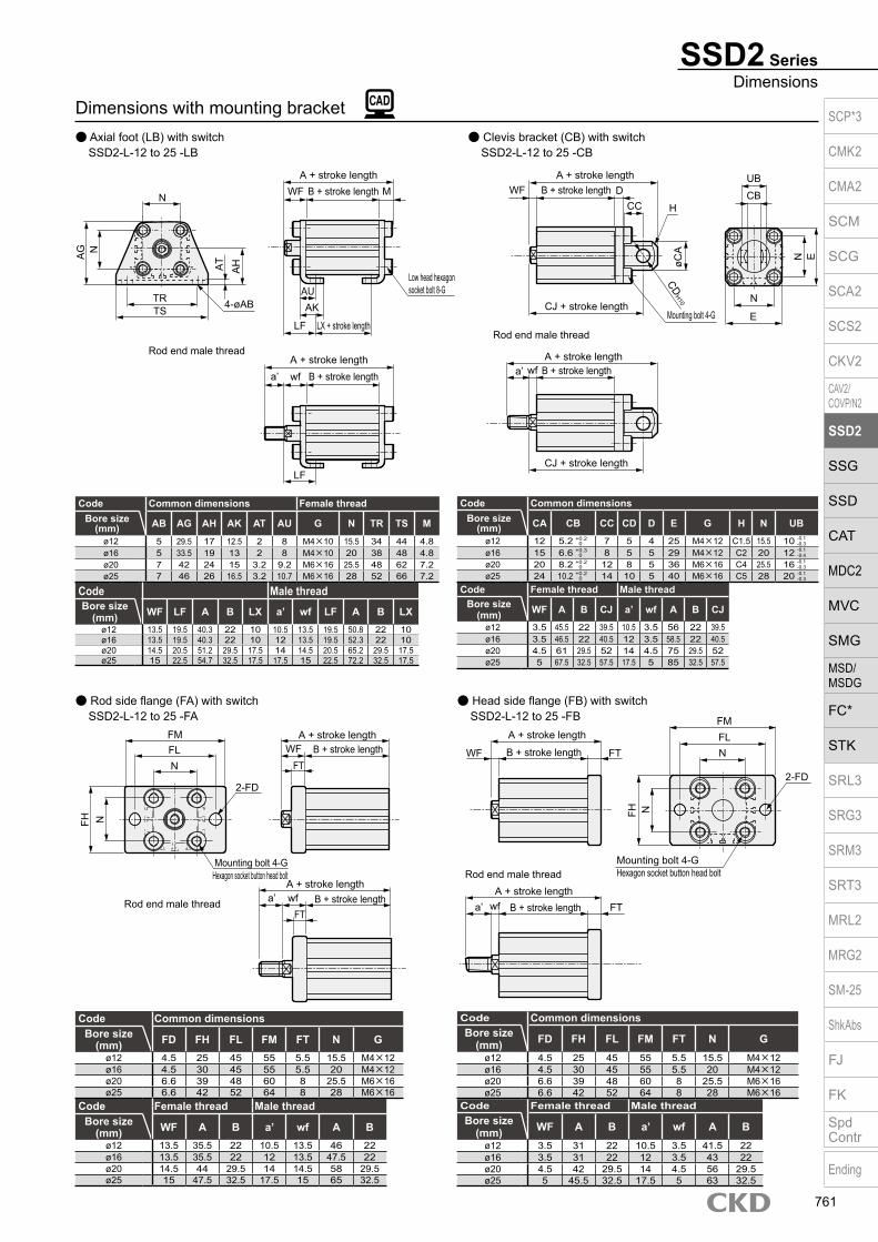
Dimensions with mounting bracket Axial foot (LB) with switch Clevis bracket (CB) with switch SSD2-L-12 to 25 -LB SSD2-L-12 to 25 -CB
SSD2 SeriesDimensions
Code Common dimensions Female threadBore size
(mm) AB AG AH AK AT AU G N TR TS M
ø12 5 29.5 17 12.5 2 8 M4×10 15.5 34 44 4.8ø16 5 33.5 19 13 2 8 M4×10 20 38 48 4.8ø20 7 42 24 15 3.2 9.2 M6×16 25.5 48 62 7.2ø25 7 46 26 16.5 3.2 10.7 M6×16 28 52 66 7.2
Code Female thread Male threadBore size
(mm) WF A B CJ a’ wf A B CJ
ø12 3.5 45.5 22 39.5 10.5 3.5 56 22 39.5ø16 3.5 46.5 22 40.5 12 3.5 58.5 22 40.5ø20 4.5 61 29.5 52 14 4.5 75 29.5 52ø25 5 67.5 32.5 57.5 17.5 5 85 32.5 57.5
Code Common dimensionsBore size
(mm) CA CB CC CD D E G H N UB
ø12 12 5.2 7 5 4 25 M4×12 C1.5 15.5 10ø16 15 6.6 8 5 5 29 M4×12 C2 20 12ø20 20 8.2 12 8 5 36 M6×16 C4 25.5 16ø25 24 10.2 14 10 5 40 M6×16 C5 28 20
+ 0.3 0
+ 0.2 0
+ 0.2 0
+ 0.2 0
-0.1-0.4
-0.1-0.3
-0.1-0.3
-0.1-0.3
Code Male threadBore size
(mm) WF LF A B LX a’ wf LF A B LXø12 13.5 19.5 40.3 22 10 10.5 13.5 19.5 50.8 22 10ø16 13.5 19.5 40.3 22 10 12 13.5 19.5 52.3 22 10ø20 14.5 20.5 51.2 29.5 17.5 14 14.5 20.5 65.2 29.5 17.5ø25 15 22.5 54.7 32.5 17.5 17.5 15 22.5 72.2 32.5 17.5
Rod side flange (FA) with switch SSD2-L-12 to 25 -FA
Head side flange (FB) with switch SSD2-L-12 to 25 -FB
Code Common dimensionsBore size
(mm) FD FH FL FM FT N Gø12 4.5 25 45 55 5.5 15.5 M4×12ø16 4.5 30 45 55 5.5 20 M4×12ø20 6.6 39 48 60 8 25.5 M6×16ø25 6.6 42 52 64 8 28 M6×16
Code Female thread Male threadBore size
(mm) WF A B a’ wf A Bø12 13.5 35.5 22 10.5 13.5 46 22ø16 13.5 35.5 22 12 13.5 47.5 22ø20 14.5 44 29.5 14 14.5 58 29.5ø25 15 47.5 32.5 17.5 15 65 32.5
Code Common dimensionsBore size
(mm) FD FH FL FM FT N Gø12 4.5 25 45 55 5.5 15.5 M4×12ø16 4.5 30 45 55 5.5 20 M4×12ø20 6.6 39 48 60 8 25.5 M6×16ø25 6.6 42 52 64 8 28 M6×16
Code Female thread Male threadBore size
(mm) WF A B a’ wf A Bø12 3.5 31 22 10.5 3.5 41.5 22ø16 3.5 31 22 12 3.5 43 22ø20 4.5 42 29.5 14 4.5 56 29.5ø25 5 45.5 32.5 17.5 5 63 32.5
N
AG N
TRTS
AT
AH
4-øAB
WFA + stroke length
B + stroke length M
AUAK
Low head hexagon socket bolt 8-G
LX + stroke lengthLF
A + stroke lengthB + stroke lengtha’ wf
LF
Rod end male thread
N
FM
FH
WF
Mounting bolt 4-GHexagon socket button head bolt
A + stroke lengthB + stroke lengtha’ wf FT
FL
Rod end male thread
A + stroke length
B + stroke length FT N
2-FD
N
WF
A + stroke lengthB + stroke lengtha’ wf
Rod end male thread
A + stroke lengthB + stroke length
H
CJ + stroke lengthMounting bolt 4-G
N
E
E
CBCC
UBD
øCA
CDH10
CJ + stroke length
A + stroke lengthB + stroke length
FM
NFH
N
2-FD
Mounting bolt 4-GHexagon socket button head bolt
Rod end male thread
FT
A + stroke lengthB + stroke length
FTa’ wf
WFFL
SCP*3
CMK2
CMA2
SCM
SCG
SCA2
SCS2
CKV2
CAV2/COVP/N2
SSD2
SSG
SSD
CAT
MDC2
MVC
SMG
MSD/MSDG
FC*
STK
SRL3
SRG3
SRM3
SRT3
MRL2
MRG2
SM‑25
ShkAbs
FJ
FK
SpdContr
Ending
761
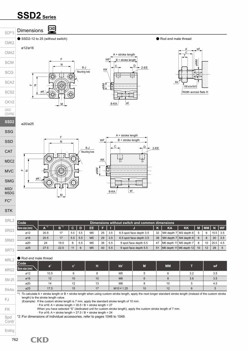
Dimensions SSD2-12 to 25 (without switch) Rod end male thread
Code Dimensions without switch and common dimensionsBore size (mm) A *1 B *1 C D EE F I J K KA KK M MM N WF
ø12 20.5 17 5.5 5.5 M5 25 3.5 6.5 spot face depth 3.5 32 M4 depth 7 M3 depth 6 5 6 15.5 3.5
ø16 20.5 17 5.5 5.5 M5 29 3.5 6.5 spot face depth 3.5 38 M4 depth 7 M4 depth 8 6 8 20 3.5
ø20 24 19.5 8 5.5 M5 36 5.5 9 spot face depth 5.5 47 M6 depth 11 M5 depth 7 8 10 25.5 4.5
ø25 27.5 22.5 11 6 M5 40 5.5 9 spot face depth 5.5 51 M6 depth 11 M6 depth 12 10 12 28 5
Codea’ c’ H kk’ M MM T wf
Bore size (mm)ø12 10.5 9 8 M5 5 6 3.2 3.5
ø16 12 10 10 M6 6 8 3.6 3.5
ø20 14 12 13 M8 8 10 5 4.5
ø25 17.5 15 17 M10×1.25 10 12 6 5
Rod end male thread
*1 : To calculate A + stroke length or B + stroke length when using custom stroke length, apply the next longer standard stroke length (instead of the custom stroke length) to the stroke length value.
(Example) If the custom stroke length is 7 mm, apply the standard stroke length of 10 mm. · For ø16: A + stroke length = 30.5 / B + stroke length = 27 When you have selected “S” (dedicated unit for custom stroke length), apply the custom stroke length of 7 mm. · For ø16: A + stroke length = 27.5 / B + stroke length = 24*2 : For dimensions of individual accessories, refer to pages 1046 to 1049.
ø12/ø16
ø20/ø25
SSD2 Series
a’c’
T
wf
øMM
kk’Width across flats M
Width across flats H
øMM
WF
KK
øI
C D
8-KA
2-EE
A + stroke length
B + stroke lengthF
8-JMounting hole
øK
F N
M
N
F
8-JMounting hole
F N
M
N
øK
øMM
WF
KK
øI
C D
8-KA
2-EE
A + stroke lengthB + stroke length
SCP*3
CMK2
CMA2
SCM
SCG
SCA2
SCS2
CKV2
CAV2/COVP/N2
SSD2
SSG
SSD
CAT
MDC2
MVC
SMG
MSD/MSDG
FC*
STK
SRL3
SRG3
SRM3
SRT3
MRL2
MRG2
SM‑25
ShkAbs
FJ
FK
SpdContr
Ending
762

Dimensions with mounting bracket Axial foot (LB) without switch Clevis bracket (CB) without switch SSD2-12 to 25 -LB SSD2-12 to 25 -CB
SSD2 SeriesDimensions
Code Common dimensions Female thread
Code Male thread
Bore size (mm) AB AG AH AK AT AU G N TR TS M
ø12 5 29.5 17 12.5 2 8 M4×10 15.5 34 44 4.8ø16 5 33.5 19 13 2 8 M4×10 20 38 48 4.8ø20 7 42 24 15 3.2 9.2 M6×16 25.5 48 62 7.2ø25 7 46 26 16.5 3.2 10.7 M6×16 28 52 66 7.2
Bore size (mm) WF LF A B LX a’ wf LF A B LX
ø12 13.5 19.5 35.3 17 5 10.5 13.5 19.5 45.8 17 5ø16 13.5 19.5 35.3 17 5 12 13.5 19.5 47.3 17 5ø20 14.5 20.5 41.2 19.5 7.5 14 14.5 20.5 55.2 19.5 7.5ø25 15 22.5 44.7 22.5 7.5 17.5 15 22.5 62.2 22.5 7.5
Code Common dimensionsBore size
(mm) CA CB CC CD D E G H N UB
ø12 12 5.2 7 5 4 25 M4×12 C1.5 15.5 10ø16 15 6.6 8 5 5 29 M4×12 C2 20 12ø20 20 8.2 12 8 5 36 M6×16 C4 25.5 16ø25 24 10.2 14 10 5 40 M6×16 C5 28 20
Code Female thread Male threadBore size
(mm) WF A B CJ a’ wf A B CJ
ø12 3.5 40.5 17 34.5 10.5 3.5 51 17 34.5ø16 3.5 41.5 17 35.5 12 3.5 53.5 17 35.5ø20 4.5 51 19.5 42 14 4.5 65 19.5 42ø25 5 57.5 22.5 47.5 17.5 5 75 22.5 47.5
+ 0.3 0
+ 0.2 0
+ 0.2 0
+ 0.2 0
-0.1-0.4
-0.1 -0.3
-0.1 -0.3
-0.1 -0.3
Rod side flange (FA) without switch SSD2-12 to 25 -FA
Head side flange (FB) without switch SSD2-12 to 25 -FB
Code Common dimensionsBore size
(mm) FD FH FL FM FT N G
ø12 4.5 25 45 55 5.5 15.5 M4×12ø16 4.5 30 45 55 5.5 20 M4×12ø20 6.6 39 48 60 8 25.5 M6×16ø25 6.6 42 52 64 8 28 M6×16
Code Female thread Male threadBore size
(mm) WF A B a’ wf A B
ø12 13.5 30.5 17 10.5 13.5 41 17ø16 13.5 30.5 17 12 13.5 42.5 17ø20 14.5 34 19.5 14 14.5 48 19.5ø25 15 37.5 22.5 17.5 15 55 22.5
Code Common dimensionsBore size
(mm) FD FH FL FM FT N G
ø12 4.5 25 45 55 5.5 15.5 M4×12ø16 4.5 30 45 55 5.5 20 M4×12ø20 6.6 39 48 60 8 25.5 M6×16ø25 6.6 42 52 64 8 28 M6×16
Code Female thread Male threadBore size
(mm) WF A B a’ wf A B
ø12 3.5 26 17 10.5 3.5 36.5 17ø16 3.5 26 17 12 3.5 38 17ø20 4.5 32 19.5 14 4.5 46 19.5ø25 5 35.5 22.5 17.5 5 53 22.5
Note: ø20: LB cannot be selected for 5 mm stroke length.
N
AG N
TRTS
AT
AH
4-øAB
WFA + stroke length
B + stroke length M
AUAK
Low head hexagon socket bolt 8-G
LX + stroke lengthLF
A + stroke lengthB + stroke lengtha’ wf
LF
Rod end male thread
N
FM
FH
WF
Mounting bolt 4-GHexagon socket button head bolt
A + stroke lengthB + stroke lengtha’ wf FT
FL
Rod end male thread
A + stroke length
B + stroke length FT N
2-FD
N
WF
A + stroke lengthB + stroke lengtha’ wf
Rod end male thread
A + stroke lengthB + stroke length
H
CJ + stroke lengthMounting bolt 4-G
N
E
E
CBCC
UBD
øCA
CDH10
CJ + stroke length
A + stroke lengthB + stroke length
FM
NFH
N
2-FD
Mounting bolt 4-GHexagon socket button head bolt
Rod end male thread
FT
A + stroke lengthB + stroke length
FTa’ wf
WFFL
SCP*3
CMK2
CMA2
SCM
SCG
SCA2
SCS2
CKV2
CAV2/COVP/N2
SSD2
SSG
SSD
CAT
MDC2
MVC
SMG
MSD/MSDG
FC*
STK
SRL3
SRG3
SRM3
SRT3
MRL2
MRG2
SM‑25
ShkAbs
FJ
FK
SpdContr
Ending
763

SSD2 Series
Dimensions SSD2-L-32 to 100 (with switch/TOH/V, T5H/V, T2H/V, T3H/V) Rod end male thread
Switch dimensions Reed T0H/T0V, T5H/T5V Proximity T2H/T2V, T3H/T3V Proximity T2WH/T2WV, T3WH/T3WVBore size (mm) HD *2 RD *2 HD *2 RD *2 HD RD
ø32 4 9.5 4 9.5 6 11.5ø40 7 12 7 12 8.5 13.5ø50 7.5 12.5 7.5 12.5 9 14ø63 12.5 13 12.5 13 14 14.5ø80 17.5 15.5 17.5 15.5 19 17
ø100 23 19.5 23 19.5 24.5 21
Codea’ c’ H kk’ M MM T wf
Bore size (mm)ø32 23.5 20.5 22 M14×1.5 14 16 8 5ø40 23.5 20.5 22 M14×1.5 14 16 8 5ø50 28.5 26 27 M18×1.5 17 20 11 5ø63 28.5 26 27 M18×1.5 17 20 11 5ø80 35.5 32.5 32 M22×1.5 22 25 13 8
ø100 35.5 32.5 41 M26×1.5 27 30 16 8
Rod end male thread
*1 : To calculate A + stroke length or B + stroke length when using custom stroke length, apply the next longer standard stroke length (instead of the custom stroke length) to the stroke length value.
(Example) If the custom stroke length is 7 mm, apply the standard stroke length of 10 mm. · For ø32: A + stroke length = 40 B + stroke length = 33 When you have selected “S” (dedicated unit for custom stroke length), apply the custom stroke length of 7 mm. · For ø32: A + stroke length = 37 B + stroke length = 30*2 : HD and RD dimensions for 5 mm stroke length differ from these dimensions according to the setting.*3 : Refer to page 1044 for HD, RD and protruding dimensions of the 2-color display, off-delay, AC magnetic field proof, T1* and T8* switches.*4 : Dimensions in ( ) of FA are for the radial lead wire.*5 : For dimensions of individual accessories, refer to pages 1046 to 1049.*6 : Dimensions in ( ) of codes A and B are for stroke lengths of more than 50 mm.*7 : The ø32 bore size with a 5 mm stroke and without a switch has a port size of M5.*8 : Dimensions in ( ) of codes C and D are when the value is for a 5 mm stroke without switch.
SSD2-32 to 100 (without switch)
Code Without switch Common dimensions with switchBore size (mm) A *1, *6 B *1, *6 A *1 B *1 C *8 D *8 EE F FA *4 FB G H I J K KA KK M MM N O WF
ø32 30(40) 23(33) 40 33 8(10) 8(5.5) Rc1/8 *7 45 23(26.5) 20.5 49.5 12.5 5.5 9 spot faceDepth 5.5 60 M6 depth 11 M8 depth 13 14 16 34 4.5 7
ø40 36.5(46.5) 29.5(39.5) 46.5 39.5 12(11.5) 8.5(8) Rc1/8 52 26.5(30) 27.5 57 15 5.5 9 spot faceDepth 5.5 69 M6 depth 11 M8 depth 13 14 16 40 5 7
ø50 38.5(48.5) 30.5(40.5) 48.5 40.5 10.5 10.5 Rc1/4 64 32.5(36) 28.5 71 18 6.9 11 spot faceDepth 6.5 86 M8 depth 13 M10 depth 15 17 20 50 7 8
ø63 44(54) 36(46) 54 46 13 11 Rc1/4 77 39(42.5) 28.5 84 23 8.7 14 spot faceDepth 9 103 M10 depth 25 M10 depth 15 17 20 60 7 8
ø80 53.5(63.5) 43.5(53.5) 63.5 53.5 16 13 Rc3/8 98 49.5(53) 28.5 104 31 10.5 17.5 spot faceDepth 11 132 M12 depth 28 M16 depth 21 22 25 77 6 10
ø100 65(75) 53(63) 75 63 23 15 Rc3/8 117 59(62.5) 28.5 123.5 38 10.5 17.5 spot faceDepth 11 156 M12 depth 28 M20 depth 27 27 30 94 6.5 12
a’c’
T
wf
øMM
kk’Width across flats M
Width across flats H
*4
øK
G N
M
N
0F FB
FA
F
H 8-JMounting hole
øMM
WF
KK
RD
C D
HD
2-EE
8-KAøI
A + stroke lengthB + stroke length
øK
øMM
WF
KK
C D 2-EE
8-KA øI
A + stroke lengthB + stroke length
G
M
N
0F N
F
H 8-JMounting hole
SCP*3
CMK2
CMA2
SCM
SCG
SCA2
SCS2
CKV2
CAV2/COVP/N2
SSD2
SSG
SSD
CAT
MDC2
MVC
SMG
MSD/MSDG
FC*
STK
SRL3
SRG3
SRM3
SRT3
MRL2
MRG2
SM‑25
ShkAbs
FJ
FK
SpdContr
Ending
764

Dimensions Axial foot (LB) SSD2-(L)-32 to 100 -LB
Code Common dimensions Female threadBore size
(mm) AB AD AE AG AH AK AT AU G N TR TS M WF LF Without switch With switchA B LX A B LX
ø32 7 18.5 13 57 30 17 3.2 11.2 M6×16 34 57 71 7.2 17 25 47.2(57.2) 23(33) 7(17) 57.2 33 17ø40 7 18 13 64 33 18.2 3.2 11.2 M6×16 40 64 78 7.2 17 25 53.7(63.7) 29.5(39.5) 13.5(23.5) 63.7 39.5 23.5ø50 9 22 14 78 39 22.7 3.2 14.7 M8×20 50 79 95 8.2 18 29.5 56.7(66.7) 30.5(40.5) 7.5(17.5) 66.7 40.5 17.5ø63 11 26 16 91.5 46 25.2 3.2 16.2 M10×25 60 95 113 9.2 18 31 63.2(73.2) 36(46) 10(20) 73.2 46 20ø80 13 31.5 20.5 114 59 30.5 4.5 19.5 M12×40 77 118 140 11.5 20 35 75(85) 43.5(53.5) 13.5(23.5) 85 53.5 23.5
ø100 13 35 24 136 71 35.5 6 23 M12×40 94 137 162 13 22 39 88(98) 53(63) 19(29) 98 63 29Code Male threadBore size
(mm) a’ wf LF Without switch With switchA B LX A B LX
ø32 23.5 15 23 68.7(78.7) 23(33) 7(17) 78.7 33 17ø40 23.5 15 23 75.2(85.2) 29.5(39.5) 13.5(23.5) 85.2 39.5 23.5ø50 28.5 15 26.5 82.2(92.2) 30.5(40.5) 7.5(17.5) 92.2 40.5 17.5ø63 28.5 15 28 88.7(98.7) 36(46) 10(20) 98.7 46 20ø80 35.5 18 33 108.5(118.5) 43.5(53.5) 13.5(23.5) 118.5 53.5 23.5
ø100 35.5 18 35 119.5(129.5) 53(63) 19(29) 129.5 63 29* Dimensions in ( ) are for stroke lengths of more than 50 mm.
* Dimensions in ( ) are for stroke lengths of more than 50 mm.
Clevis bracket (CB) SSD2-(L)-32 to 100 -CB
Code Common dimensions Female thread Male threadBore size
(mm) AC CB CC CD D E G MR N UB WFWithout switch With switch
a’ wfWithout switch With switch
A B CJ A B CJ A B CJ A B CJø32 4.5 18.2 14 10 5 45 M6×16 10 34 36 7 60(70) 23(33) 50 70 33 60 23.5 5 81.5(91.5) 23(33) 48 91.5 33 58ø40 5 18.2 14 10 6 52 M6×16 10 40 36 7 68.5(78.5) 29.5(39.5) 58.5 78.5 39.5 68.5 23.5 5 90(100) 29.5(39.5) 56.5 100 39.5 66.5ø50 6 22.2 20 14 7 64 M8×20 14 50 44 8 80.5(90.5) 30.5(40.5) 66.5 90.5 40.5 76.5 28.5 5 106(116) 30.5(40.5) 63.5 116 40.5 73.5ø63 7 22.2 20 14 8 77 M10×25 14 60 44 8 88(98) 36(46) 74 98 46 84 28.5 5 113.5(123.5) 36(46) 71 123.5 46 81ø80 9 28.2 27 18 10 98 M12×40 18 77 56 10 109.5(119.5) 43.5(53.5) 91.5 119.5 53.5 101.5 35.5 8 143(153) 43.5(53.5) 89.5 153 53.5 99.5
ø100 12 32.2 31 22 13 117 M12×40 22 94 64 12 132(142) 53(63) 110 142 63 120 35.5 8 163.5(173.5) 53(63) 106 173.5 63 116
SSD2 SeriesDimensions
Note: LB cannot be selected when B + stroke length is at or less than the stroke value below. ø80: 72 or less, ø: 69 or less
NTRTS
4-øAB
AT A
H
LF
A + stroke length
Rod end male thread
B + stroke lengtha’ wf
LX + stroke length
A + stroke lengthB + stroke length
Low head hexagon socket bolt 4-G
LF
WF
AUAK
M
N
A + stroke length
Rod end male thread
B + stroke lengtha’ wf
A + stroke lengthB + stroke lengthWF
CJ + stroke lengthCJ + stroke length
CBCC
UB
D
NE
E
CDH10
Mounting bolt 4-GAC
RMR
AD
AE
AG
-0.1 -0.3
+ 0.2 0
SCP*3
CMK2
CMA2
SCM
SCG
SCA2
SCS2
CKV2
CAV2/COVP/N2
SSD2
SSG
SSD
CAT
MDC2
MVC
SMG
MSD/MSDG
FC*
STK
SRL3
SRG3
SRM3
SRT3
MRL2
MRG2
SM‑25
ShkAbs
FJ
FK
SpdContr
Ending
765

Dimensions Rod side flange (FA)
SSD2-(L)-32 to 100 -FA
SSD2 Series
Code Common dimensions Female thread Male threadBore size
(mm) FC FD FH FL FM FT N G WFWithout switch With switch
a’ wfWithout switch With switch
A B A B A B A Bø32 34 5.5 48 56 65 8 34 M6×16 17 40(50) 23(33) 50 33 23.5 15 61.5(71.5) 23(33) 71.5 33
ø40 40 5.5 54 62 72 8 40 M6×16 17 46.5(56.5) 29.5(39.5) 56.5 39.5 23.5 15 68(78) 29.5(39.5) 78 39.5
ø50 50 6.6 67 76 89 9 50 M8×20 18 48.5(58.5) 30.5(40.5) 58.5 40.5 28.5 15 74(84) 30.5(40.5) 84 40.5
ø63 60 9 80 92 108 9 60 M10×25 18 54(64) 36(46) 64 46 28.5 15 79.5(89.5) 36(46) 89.5 46
ø80 77 11 99 116 134 11 77 M12×40 20 63.5(73.5) 43.5(53.5) 73.5 53.5 35.5 18 97(107) 43.5(53.5) 107 53.5
ø100 94 11 117 136 154 11 94 M12×40 22 75(85) 53(63) 85 63 35.5 18 106.5(116.5) 53(63) 116.5 63
Head side flange (FB) SSD2-(L)-32 to 100 -FB
Code Common dimensions Female thread Male thread
Bore size (mm) FC FD FH FL FM FT N G WF
Without switch With switcha’ wf
Without switch With switchA B A B A B A B
ø32 34 5.5 48 56 65 8 34 M6×16 7 38(48) 23(33) 48 33 23.5 5 59.5(69.5) 23(33) 69.5 33
ø40 40 5.5 54 62 72 8 40 M6×16 7 44.5(54.5) 29.5(39.5) 54.5 39.5 23.5 5 66(76) 29.5(39.5) 76 39.5
ø50 50 6.6 67 76 89 9 50 M8×20 8 47.5(57.5) 30.5(40.5) 57.5 40.5 28.5 5 73(83) 30.5(40.5) 83 40.5
ø63 60 9 80 92 108 9 60 M10×25 8 53(63) 36(46) 63 46 28.5 5 78.5(88.5) 36(46) 88.5 46
ø80 77 11 99 116 134 11 77 M12×40 10 64.5(74.5) 43.5(53.5) 74.5 53.5 35.5 8 98(108) 43.5(53.5) 108 53.5
ø100 94 11 117 136 154 11 94 M12×40 12 76(86) 53(63) 86 63 35.5 8 107.5(117.5) 53(63) 117.5 63
* Dimensions in ( ) are for stroke lengths of more than 50 mm.
* Dimensions in ( ) are for stroke lengths of more than 50 mm.
Rod end male thread
A + stroke lengthB + stroke length
A + stroke lengthB + stroke lengtha’ wf
FTFT
FH FC
FM
NFL
4-FD
Mounting bolt 4-Gø32 to ø63: Hexagon socket button head boltø80/ø100: Special bolt
WF
FH FC
A + stroke length
Rod end male thread
B + stroke lengtha’ wfA + stroke lengthB + stroke lengthWF FT4-FD
FLN
Mounting bolt 4-G
FM
FT
ø32 to ø63: Hexagon socket button head boltø80/ø100: Special bolt
SCP*3
CMK2
CMA2
SCM
SCG
SCA2
SCS2
CKV2
CAV2/COVP/N2
SSD2
SSG
SSD
CAT
MDC2
MVC
SMG
MSD/MSDG
FC*
STK
SRL3
SRG3
SRM3
SRT3
MRL2
MRG2
SM‑25
ShkAbs
FJ
FK
SpdContr
Ending
766

M E M OM E M OSCP*3
CMK2
CMA2
SCM
SCG
SCA2
SCS2
CKV2
CAV2/COVP/N2
SSD2
SSG
SSD
CAT
MDC2
MVC
SMG
MSD/MSDG
FC*
STK
SRL3
SRG3
SRM3
SRT3
MRL2
MRG2
SM‑25
ShkAbs
FJ
FK
SpdContr
Ending
767

Compact cylinder double acting/single rod (large bore size)
SSD2 Series Bore size: ø125/ø140/ø160/ø180/ø200
SpecificationsItem SSD2
SSD2-L (with switch)Bore size mm ø125 ø140 ø160 ø180 ø200Actuation Double actingWorking fluid Compressed airMax. working pressure MPa 1.0 (≈150 psi, 10 bar) 0.7 (≈100 psi, 7 bar)Min. working pressure MPa 0.05 (≈7.3 psi, 0.5 bar)Proof pressure MPa 1.6 (≈230 psi, 16 bar) 1.05 (≈150 psi, 10.5 bar)Ambient temperature °C -10 (14°F) to 60 (140°F) (no freezing)Port size Rc3/8 Rc1/2Stroke tolerance mm +2.0
0
Working piston speed mm/s 50 to 300 20 to 300Cushion With rubber cushion (standard)Lubrication Not required (use turbine oil class 1 ISO VG32 if necessary for lubrication)Allowable absorbed energy J
With rubber cushion 6.52 6.52 7.78 12.4Without cushion -
Stroke lengthBore size (mm) Standard stroke length (mm) Max. stroke length (mm) Min. stroke length (mm)
ø12510, 20, 30, 40, 5075, 100, 125, 150175, 200, 250, 300
300 1ø140ø160ø180ø200
*1: For the type with switch, refer to the table of switch mounting quantity and minimum stroke length.
Number of installed switches and min. stroke length (mm)
Note: Less than 10 mm with the 2-color display, off-delay, AC magnetic field proof, T1* or T8* switch is not available.
Switch quantity 1 2 3 4 5Switch model No.
T* T* T* T* T*Bore size (mm)
ø125 5 5 40 55 70ø140 5 5 40 55 70ø160 5 5 40 55 70ø180 5 5 40 55 70ø200 5 5 40 55 70
JIS symbol
SCP*3
CMK2
CMA2
SCM
SCG
SCA2
SCS2
CKV2
CAV2/COVP/N2
SSD2
SSG
SSD
CAT
MDC2
MVC
SMG
MSD/MSDG
FC*
STK
SRL3
SRG3
SRM3
SRT3
MRL2
MRG2
SM‑25
ShkAbs
FJ
FK
SpdContr
Ending
768

SSD2 (Large bore size) SeriesSpecifications
Stroke length (mm) 10 20 30 40 50 75 100Bore size (mm) No switch With switch No switch With switch No switch With switch No switch With switch No switch With switch No switch With switch No switch With switch
ø125 4.58 4.68 4.85 4.95 5.11 5.21 5.38 5.48 5.64 5.74 6.30 6.40 6.97 7.07ø140 6.36 6.47 6.66 6.77 6.97 7.08 7.27 7.38 7.58 7.69 8.34 8.45 9.10 9.21ø160 8.64 8.76 9.02 9.14 9.40 9.52 9.78 9.90 10.16 10.28 11.11 11.23 12.06 12.18ø180 12.98 13.06 13.38 13.46 13.78 13.86 14.18 14.26 14.58 14.66 15.59 15.67 16.59 16.67ø200 17.23 17.31 17.69 17.77 18.16 18.24 18.62 18.70 19.08 19.16 20.23 20.31 21.39 21.47
Cylinder weight table (the weight of the switches is when there are 2 cylinder switches.)
Switch specifications 1-color/2-color display/for AC magnetic field proof
*1 : Refer to Ending Page 1 for detailed switch specifications and dimensions. *2 : Switches other than the above models, such as switches with connectors, are also available. Refer to Ending Page 1. *3 : The max. load current is 20 mA at 25°C. The current is lower than 20 mA if the operating ambient temperature around the switch is higher than 25˚C.
(5 to 10 mA at 60°C) *4 : Switch for AC magnetic field (T2YD/T2YDT) cannot be used in DC magnetic field.
Stroke length (mm) 125 150 175 200 250 300Bore size (mm) No switch With switch No switch With switch No switch With switch No switch With switch No switch With switch No switch With switch
ø125 7.63 7.73 8.30 8.40 8.96 9.06 9.62 9.72 10.95 11.05 12.27 12.37ø140 9.86 9.97 10.63 10.74 11.39 11.50 12.15 12.26 13.68 13.79 15.20 15.31ø160 13.01 13.13 13.96 14.08 14.91 15.03 15.86 15.98 17.76 17.88 19.66 19.78ø180 17.59 17.67 18.59 18.67 19.60 19.68 20.60 20.68 22.60 22.68 24.61 24.69ø200 22.54 22.62 23.70 23.78 24.85 24.93 26.01 26.09 28.32 28.40 30.63 30.71
ItemProximity 2-wire Proximity 2-wire Proximity 3-wire Reed 2-wire Proximity 2-wire
T1H/T1VT2H/T2V/
T2JH/T2JVT2YH/T2YV
T2WH/ T2WV
T3H/T3VT3PH/T3PV
T3YH/T3YV
T3WH/ T3WV
T0H/T0V T5H/T5V T8H/T8VT2YD(*4)T2YDT
ApplicationsFor programmable
controller, relay, compact solenoid valve
Dedicated for programmable controller
For programmable controller, relay
For programmable controller, relay
For programmable controller, relay, IC circuit (no indicator
lamp), serial connection
For programmable controller, relay
For programmable
controllerOutput method - NPN output PNP output NPN output NPN output -Pwr. supp. V. - 10 to 28 VDC -Load voltage 85 to 265 VAC 10 to 30 VDC 24 VDC ±10% 30 VDC or less 12/24 VDC 100/110 VAC 5/12/24 VDC 100/110 VAC 12/24 VDC 110 VAC 220 VAC 24 VDC ±10%Load current 5 to 100 mA 5 to 20 mA (*3) 100 mA or less 50 mA or less 5 to 50 mA 7 to 20 mA 50 mA or less 20 mA or less 5 to 50 mA 7 to 20 mA 7 to 10 mA 5 to 20 mA
Indicator lamp
LED(Lit when
ON)
LED (Lit when ON)
Red/green LED (Lit
when ON)
Red/green LED (Lit
when ON)
LED (Lit when ON)
Yellow LED (Lit
when ON)
Red/green LED (Lit
when ON)
Red/green LED (Lit
when ON)
LED(Lit when ON)
Without indicator lamp
LED(Lit when ON)
Red/green LED
(Lit when ON)Leakage current
≤ 1 mA at 100 VAC, ≤ 2 mA at 200 VAC
1 mA or less 10 μA or less 0 mA1 mA or
less
Weight g1 m:333 m:875 m:142
1 m:183 m:495 m:80
1 m:333 m:875 m:142
1 m:183 m:495 m:80
1 m:183 m:495 m:80
1 m:333 m:875 m:142
1 m:183 m:495 m:80
1 m:18 3 m:49 5 m:801 m:333 m:875 m:142
1 m:613 m:1665 m:272
Bore size (mm)
Operating direction
Working pressure MPa0.1 0.15 0.2 0.3 0.4 0.5 0.6 0.7 0.8 0.9 1.0
ø125Push 1.23×10³ 1.84×10³ 2.45×10³ 3.68×10³ 4.91×10³ 6.14×10³ 7.36×10³ 8.59×10³ 9.82×10³ 1.10×10⁴ 1.23×10⁴
Pull 1.13×10³ 1.70×10³ 2.26×10³ 3.39×10³ 4.52×10³ 5.65×10³ 6.79×10³ 7.92×10³ 9.05×10³ 1.02×10⁴ 1.13×10⁴
ø140Push 1.54×10³ 2.31×10³ 3.08×10³ 4.62×10³ 6.16×10³ 7.70×10³ 9.24×10³ 1.08×10⁴ 1.23×10⁴ 1.39×10⁴ 1.54×10⁴
Pull 1.44×10³ 2.16×10³ 2.89×10³ 4.33×10³ 5.77×10³ 7.22×10³ 8.66×10³ 1.01×10⁴ 1.15×10⁴ 1.30×10⁴ 1.44×10⁴
ø160Push 2.01×10³ 3.02×10³ 4.02×10³ 6.03×10³ 8.04×10³ 1.01×10⁴ 1.21×10⁴ 1.41×10⁴ 1.61×10⁴ 1.81×10⁴ 2.01×10⁴
Pull 1.88×10³ 2.83×10³ 3.77×10³ 5.65×10³ 7.54×10³ 9.42×10³ 1.13×10⁴ 1.32×10⁴ 1.51×10⁴ 1.70×10⁴ 1.88×10⁴
ø180Push 2.54×10³ 3.82×10³ 5.09×10³ 7.63×10³ 1.02×10⁴ 1.27×10⁴ 1.53×10⁴ 1.78×10⁴ - - -Pull 2.39×10³ 3.58×10³ 4.77×10³ 7.16×10³ 9.54×10³ 1.19×10⁴ 1.43×10⁴ 1.67×10⁴ - - -
ø200Push 3.14×10³ 4.71×10³ 6.28×10³ 9.43×10³ 1.26×10⁴ 1.57×10⁴ 1.89×10⁴ 2.20×10⁴ - - -Pull 3.02×10³ 4.52×10³ 6.03×10³ 9.05×10³ 1.21×10⁴ 1.51×10⁴ 1.81×10⁴ 2.11×10⁴ - - -
Theoretical thrust table (Unit: N)
(Unit: kg)
SCP*3
CMK2
CMA2
SCM
SCG
SCA2
SCS2
CKV2
CAV2/COVP/N2
SSD2
SSG
SSD
CAT
MDC2
MVC
SMG
MSD/MSDG
FC*
STK
SRL3
SRG3
SRM3
SRT3
MRL2
MRG2
SM‑25
ShkAbs
FJ
FK
SpdContr
Ending
769

SSD2 (Large bore size) Series
G Option
How to orderWithout switch (without magnet for switch)
With switch (built-in magnet for switch)
NSSD2
Model No.A
Bore sizeB
125 50
F Switch quantity
E
D Stroke length
Port threadC
R N
Code DescriptionModel No.SSD2 Double acting/single rod
SSD2-L Double acting/single rod/with switch
Bore size (mm)125 ø125140 ø140160 ø160180 ø180200 ø200
Port threadBlank Rc thread
NN NPT thread (ø125 to ø160) (made-to-order product)GN G thread (ø125 to ø160) (made-to-order product)
Stroke length (mm)
Refer to the stroke length table on the following page.
* Lead wire lengthBlank 1 m (standard)
3 3 m (option)5 5 m (option)
Switch quantityR 1 on rod sideH 1 on head sideD 2
OptionBlank Rod end female thread
N Rod end male threadP4
Specifications for rechargeable batteryP40
Switch model No.Lead wire Lead wire
Cont
act
VoltageDisplay
Lead Straight L-shaped AC DC Line
TOH* T0V*
Ree
d 1-color display2-wireT5H* T5V* Without indicator lamp
T8H* T8V* 1-color displayT1H* T1V*
Pro
xim
ity
1-color display2-wire
T2H* T2V*
T3H* T3V* 3-wire
T3PH* T3PV* 1-color displayT2WH* T2WV*
2-color display2-wire
T2YH* T2YV*
T3WH* T3WV* 3-wire
T3YH* T3YV*
T2JH* T2JV* 1-color display off-delay 2-wireT2YD* - 2-color display
for AC magnetic field2-wire
T2YDT* -
A
B
C
F
G
D
E
Precautions for model No. selection*1: Switches are shipped with the product. Contact CKD
if assembling before shipment is necessary.
[Example of model No.]SSD2-L-125-50-T0H-R-NModel: Compact cylinder, standardB Bore size : 125 mmC Port thread : Rc threadD Stroke length : 50mmE Switch model No. : Reed T0H switch · Lead wire length 1 mF Switch quantity : 1 on rod sideG Option : Rod end male thread
200SSD2-L 100 T0H
Switch model No.*1
SCP*3
CMK2
CMA2
SCM
SCG
SCA2
SCS2
CKV2
CAV2/COVP/N2
SSD2
SSG
SSD
CAT
MDC2
MVC
SMG
MSD/MSDG
FC*
STK
SRL3
SRG3
SRM3
SRT3
MRL2
MRG2
SM‑25
ShkAbs
FJ
FK
SpdContr
Ending
770

SSD2 (Large bore size) SeriesHow to order
Stroke length (mm)Applicable bore size
ø125 ø140 ø160 ø180 ø200
Sta
ndar
d st
roke
leng
th
10 20 30 40 50 75
100 125 150 175 200 250 300
Min. stroke length (mm) *1 1Max. stroke length (mm) 300Custom stroke length *2 In 1 mm increments
[Stroke length table]
How to order switch
Switch model No. (Item F on page 770)
*1 : Less than 5 mm for 1-color display switch and less than 10 mm for the 2-color display, off-delay, AC magnetic field proof, T1* or T8* switch are not available.
Refer to page 768 for the number of installed switches and the min. stroke length.*2 : Total length dimension with custom stroke length is handled as custom stroke dedicated
length.
SW T0H
SCP*3
CMK2
CMA2
SCM
SCG
SCA2
SCS2
CKV2
CAV2/COVP/N2
SSD2
SSG
SSD
CAT
MDC2
MVC
SMG
MSD/MSDG
FC*
STK
SRL3
SRG3
SRM3
SRT3
MRL2
MRG2
SM‑25
ShkAbs
FJ
FK
SpdContr
Ending
771
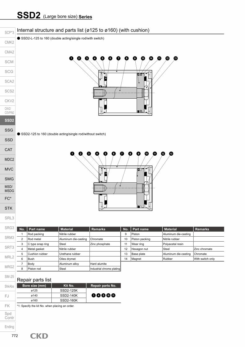
SSD2 (Large bore size) Series
Internal structure and parts list (ø125 to ø160) (with cushion) SSD2-L-125 to 160 (double acting/single rod/with switch)
SSD2-125 to 160 (double acting/single rod/without switch)
No. Part name Material Remarks No. Part name Material Remarks1 Rod packing Nitrile rubber 9 Piston Aluminum die-casting
2 Rod metal Aluminum die-casting Chromate 10 Piston packing Nitrile rubber
3 C type snap ring Steel Zinc phosphate 11 Wear ring Polyacetal resin
4 Metal gasket Nitrile rubber 12 Hexagon nut Steel Zinc chromate
5 Cushion rubber Urethane rubber 13 Base plate Aluminum die-casting Chromate
6 Bush Oiles drymet 14 Magnet Rubber With switch only
7 Body Aluminum alloy Hard alumite
8 Piston rod Steel Industrial chrome plating
Repair parts listBore size (mm) Kit No. Repair parts No.
ø125 SSD2-125K1 4 5 10 11ø140 SSD2-140K
ø160 SSD2-160K*1: Specify the kit No. when placing an order.
10 14 12 13111 2 43 7 8 95 6
10 12 13111 2 43 7 8 95 6
SCP*3
CMK2
CMA2
SCM
SCG
SCA2
SCS2
CKV2
CAV2/COVP/N2
SSD2
SSG
SSD
CAT
MDC2
MVC
SMG
MSD/MSDG
FC*
STK
SRL3
SRG3
SRM3
SRT3
MRL2
MRG2
SM‑25
ShkAbs
FJ
FK
SpdContr
Ending
772
SSD2 (Large bore size) SeriesInternal structure and parts list
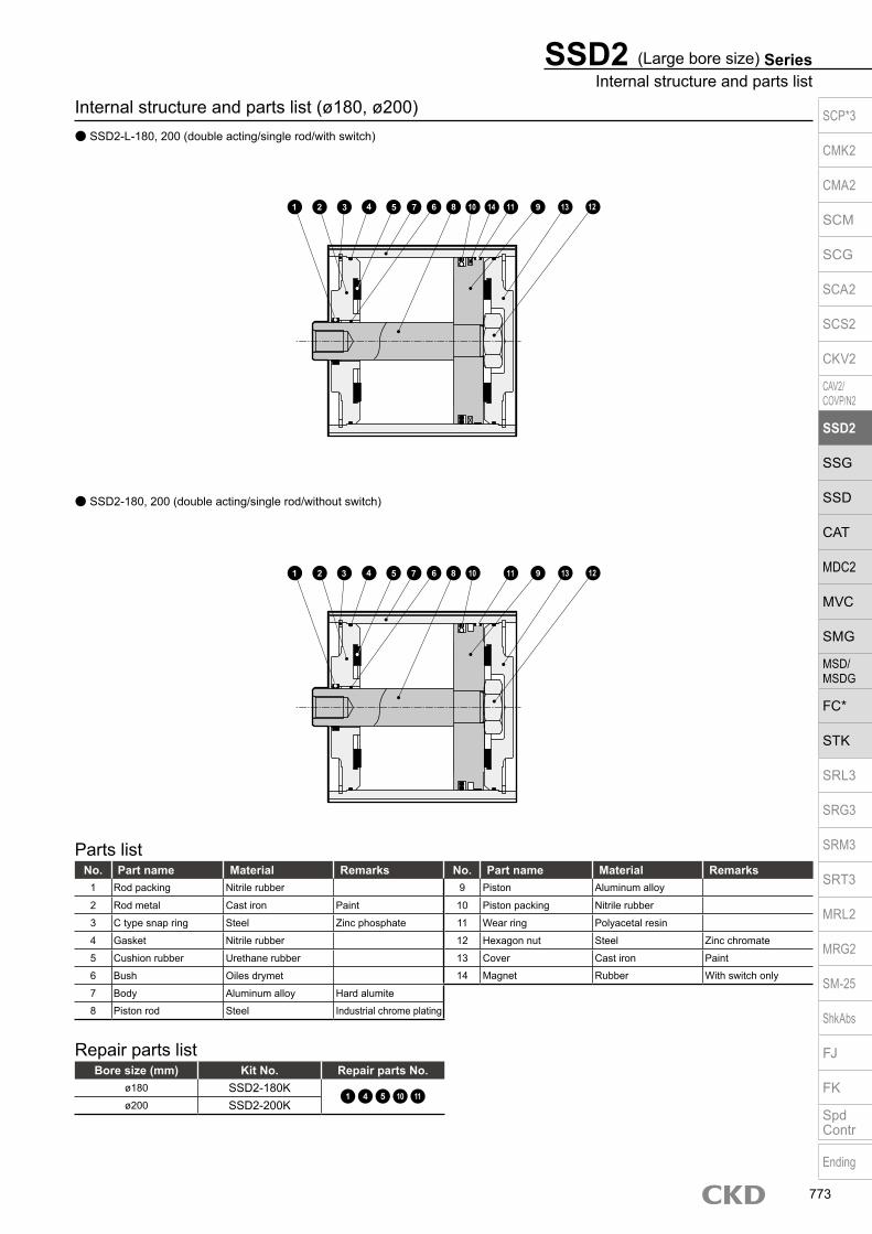
Internal structure and parts list (ø180, ø200) SSD2-L-180, 200 (double acting/single rod/with switch)
Repair parts listBore size (mm) Kit No. Repair parts No.
ø180 SSD2-180K1 4 5 10 11
ø200 SSD2-200K
Parts listNo. Part name Material Remarks No. Part name Material Remarks
1 Rod packing Nitrile rubber 9 Piston Aluminum alloy
2 Rod metal Cast iron Paint 10 Piston packing Nitrile rubber
3 C type snap ring Steel Zinc phosphate 11 Wear ring Polyacetal resin
4 Gasket Nitrile rubber 12 Hexagon nut Steel Zinc chromate
5 Cushion rubber Urethane rubber 13 Cover Cast iron Paint
6 Bush Oiles drymet 14 Magnet Rubber With switch only
7 Body Aluminum alloy Hard alumite
8 Piston rod Steel Industrial chrome plating
SSD2-180, 200 (double acting/single rod/without switch)
10 111 2 3 7 8 95 6 13 124
10 111 2 3 7 8 95 6 13 124 14
SCP*3
CMK2
CMA2
SCM
SCG
SCA2
SCS2
CKV2
CAV2/COVP/N2
SSD2
SSG
SSD
CAT
MDC2
MVC
SMG
MSD/MSDG
FC*
STK
SRL3
SRG3
SRM3
SRT3
MRL2
MRG2
SM‑25
ShkAbs
FJ
FK
SpdContr
Ending
773

Dimensions (ø125 to ø160) SSD2-(L)-125 to 160 (double acting/single rod) Rod end male thread
*1: Dimensions in ( ) of FA are for the radial lead wire.
Code T0H/V, T2H/V, T3H/V, T5/V T2YH/V, T3YH/V, T2JH/V T1H/V, T2YD T2WH/V, T3WH/V T8H/V
Bore size (mm) HD RD FA*1 FB HD RD FA
*1 FB HD RD FA*1 FB HD RD FA
*1 FB HD RD FA*1 FB
ø125 30 35 71.5(75) 44.5 28.5 33.5 77
(80) 48 28.5 33.5 82.5(85.5) 48 31.5 36.5 71.5
(75) 44.5 24 29 77(80) 48
ø140 31.5 33.5 79.5(83) 44.5 30 32 85
(88) 48 30 32 90.5(93.5) 48 33 35 79.5
(83) 44.5 25.5 27.5 85(88) 48
ø160 34 39 89.5(93) 48.5 32.5 37.5 95
(98) 52 32.5 37.5 100.5(103.5) 52 35.5 40.5 89.5
(93) 48.5 28 33 95(98) 52
Dimensions of rod end male threadCode
a’ c’ H kk’ M MM T wfBore size (mm)
ø125 45 42 46 M30×1.5 30 35 18 13
ø140 45 42 46 M30×1.5 30 35 18 13
ø160 50 47 55 M36×1.5 36 40 21 14
Code Common dimensions with switchBore size (mm) A B C D EE F I J K KA KK L M MM N WF
ø125 99 83 29 29 Rc3/8 142 12.5 20 spot face depth 13 190 M14 depth 25 M22 depth 30 72 30 35 114 16
ø140 99 83 27.5 27.5 Rc3/8 158 12.5 20 spot face depth 13 210 M14 depth 25 M22 depth 30 80 30 35 128 16
ø160 108 91 30 30 Rc3/8 178 14.7 23 spot face depth 15.2 238 M16 depth 28 M24 depth 33 90 36 40 144 17
SSD2 (Large bore size) Series
a b
HD
RDøMM
øI8-KAFAøK
b a
8-JMounting hole
FB
*1
a’
kk’
Width across flats H Width across flats M
øMM
wfc’
T
A + stroke lengthB + stroke length
KK
C DNF
L2-EE
M
F N
WF
SCP*3
CMK2
CMA2
SCM
SCG
SCA2
SCS2
CKV2
CAV2/COVP/N2
SSD2
SSG
SSD
CAT
MDC2
MVC
SMG
MSD/MSDG
FC*
STK
SRL3
SRG3
SRM3
SRT3
MRL2
MRG2
SM‑25
ShkAbs
FJ
FK
SpdContr
Ending
774

SSD2 (Large bore size) SeriesDimensions
Dimensions (ø180, ø200) SSD2-(L)-180, 200 (double acting/single rod) Rod end male thread
CodeA B C D F K L N
Bore size (mm)ø180 119 102 32.5 32.5 204 270 104 162
ø200 126 109 33.5 33.5 226 300 110 182
Code T0H/V, T2H/V, T3H/V, T5H/V T2YH/V, T3YH/V, T2JH/V T1H/V, T2YD T2WH/V, T3WH/V T8H/VBore size (mm) HD RD FA *1 HD RD FA *1 HD RD FA *1 HD RD FA *1 HD RD FA *1
ø180 39.5 43.5 99(102.5) 38.5 42.5 104.5
(107.5) 38.5 42.5 110(113) 41.5 45.5 99
(102.5) 33.5 37.5 104.5(107.5)
ø200 44.5 45.5 109.5(113) 43.5 44.5 115
(118) 43.5 44.5 120.5(123.5) 46.5 47.5 109.5
(113) 38.5 39.5 115(118)
*1: Dimensions in ( ) of FA are for the radial lead wire.*2: 2×4-M22 through hole for 20 mm or less stroke length.
504721
14
M36×1.5Width across flats 55
Width across flats 36
ø40
A + stroke length17
Ca b
D
M24 depth 33
B + stroke length
HD
RDø40
3
ø19.
5Plain washer (4)
2 x 4-M22 depth 38*2
8-ø31.5 spot face depth 26
FA36øK
F N
2-Rc1/2NF
Lb a
SCP*3
CMK2
CMA2
SCM
SCG
SCA2
SCS2
CKV2
CAV2/COVP/N2
SSD2
SSG
SSD
CAT
MDC2
MVC
SMG
MSD/MSDG
FC*
STK
SRL3
SRG3
SRM3
SRT3
MRL2
MRG2
SM‑25
ShkAbs
FJ
FK
SpdContr
Ending
775

Compact cylinder, double acting/single rod/high load
SSD2-K Series Bore size: ø12/ø16/ø20/ø25/ø32
ø40/ø50/ø63/ø80/ø100JIS symbol
SpecificationsItem
SSD2-K SSD2-KL (with switch)
Bore size mm ø12 ø16 ø20 ø25 ø32 ø40 ø50 ø63 ø80 ø100Actuation Double actingWorking fluid Compressed airMax. working pressure MPa 1.0 (≈150 psi, 10 bar)Min. working pressure MPa 0.1 (≈15 psi, 1 bar) 0.05 (≈7.3 psi, 0.5 bar)Proof pressure MPa 1.6 (≈230 psi, 16 bar)Ambient temperature °C -10 (14°F) to 60 (140°F) (no freezing)Port size M5 Rc1/8 Rc1/4 Rc3/8
Stroke tolerance mm+2.0
0Working piston speed mm/s 50 to 500 50 to 300Cushion Rubber cushionLubrication Not required (use turbine oil ISO VG32 if necessary for lubrication)Allowable absorbed energy J 0.04 0.09 0.16 0.16 0.40 0.63 0.98 1.56 2.51 3.92
Custom stroke length SSD2-K Series
ItemStandard products Optional products
Standard stroke length body with spacer Dedicated unit (-S)Model No. Refer to How to order. Add “-S” option code to the model No.
DescriptionA spacer is added to the standard stroke length body to adjust the stroke length in 1 mm increments.
Dedicated units of the required stroke length are available.
Stroke range
Bore size Stroke range Bore size Stroke range12/16 1 to 29 12, 16 6 to 29
20 to 25 1 to 49 20, 25 6 to 4932 to 100 1 to 99 32 to 100 11 to 99
Example of model No.
Model No.: SSD2-K-32-41A +4 mm spacer is added to the SSD2-K-32-45 standard cylinder to create 41 mm stroke length.B + stroke length is 88 mm.
Model No.: SSD2-K-32-41-SDedicated units for 41 mm stroke length are available.B + stroke length is 74mm.
Stroke length
*1 : When using the type with switch, refer to the table of the min. stroke length with switch.
*2 : Refer to page 789 for the min. stroke length with mounting bracket LB.
Bore size (mm)
Standard stroke length (mm)
Max. stroke length (mm)
Min. stroke length (mm)
ø12 5/10/15/2025/30
30
1
ø16ø20 5/10/15/20/25
30/35/40/45/5050
ø25ø32 5/10/15/20/25/30/
35/40/45/50/75/100
100
ø40ø50
10/15/20/2530/35/40/45/50
75/100
ø63ø80ø100
Min. stroke length with switch (1 or 2 switches)
*1: Less than 10 mm with the 2-color display, off-delay, AC magnetic field proof, T1* or T8* switch is not available.
*2: Values in ( ) are for the type with 1 on rod side.
Bore size (mm)
T0H/V / T5H/V T2H/V / T3H/V
ø1210(5)
5
ø16ø20
5
ø25ø32ø40ø50ø63ø80ø100
A + stroke length
B + stroke length
SCP*3
CMK2
CMA2
SCM
SCG
SCA2
SCS2
CKV2
CAV2/COVP/N2
SSD2
SSG
SSD
CAT
MDC2
MVC
SMG
MSD/MSDG
FC*
STK
SRL3
SRG3
SRM3
SRT3
MRL2
MRG2
SM‑25
ShkAbs
FJ
FK
SpdContr
Ending
776

SSD2-K SeriesSpecifications
Switch specifications (F switch) 1-color/2-color display
ItemProximity 2-wire Proximity 3-wire Proximity 2-wire Proximity 3-wire
F2S F3S F2H/F2VF2YH/F2YV
F3H/F3VF3PH/F3PV
(made to order)F3YH/F3YV
Applications Dedicated for programmable controller
For programmable controller, relay
Dedicated for programmable controller
For programmable controller, relay
Output method - NPN output - NPN output PNP output NPN output
Power supply voltage - 10 to 28 VDC - 10 to 28 VDC 4.5 to 28 VDC 10 to 28 VDC
Load voltage 10 to 30 VDC 30 VDC or less 10 to 30 VDC 24 VDC ±10% 30 VDC or less
Load current 5 to 20 mA 50 mA or less 5 to 20 mA 50 mA or less
Indicator lamp LED(Lit when ON)
Yellow LED(Lit when ON)
Red/greenLED
(Lit when ON)
Yellow LED(Lit when ON)
Red/greenLED
(Lit when ON)
Leakage current 1 mA or less 10 μA or less 1 mA or less 10 μA or less
Weight g 1 m:10 3 m:29
Bore size (mm)
Operating direction
Working pressure MPa0.05 0.1 0.15 0.2 0.3 0.4 0.5 0.6 0.7 0.8 0.9 1.0
ø12Push - 11.3 17.0 22.6 33.9 45.2 56.5 67.9 79.2 90.5 1.02×10² 1.13×10²
Pull - 8.48 12.7 17.0 25.4 33.9 42.4 50.9 59.4 67.9 76.3 84.8
ø16Push - 20.1 30.2 40.2 60.3 80.4 1.01×10² 1.21×10² 1.41×10² 1.61×10² 1.81×10² 2.01×10²
Pull - 15.1 22.6 30.2 45.2 60.3 75.4 90.5 1.06×10² 1.21×10² 1.36×10² 1.51×10²
ø20Push - 31.4 47.1 62.8 94.2 1.26×10² 1.57×10² 1.88×10² 2.20×10² 2.51×10² 2.83×10² 3.14×10²
Pull - 23.6 35.3 47.1 70.7 94.2 1.18×10² 1.41×10² 1.65×10² 1.88×10² 2.12×10² 2.36×10²
ø25Push - 49.1 73.6 98.2 1.47×10² 1.96×10² 2.45×10² 2.95×10² 3.44×10² 3.93×10² 4.42×10² 4.91×10²
Pull - 37.8 56.7 75.6 1.13×10² 1.51×10² 1.89×10² 2.27×10² 2.64×10² 3.02×10² 3.40×10² 3.78×10²
ø32Push - 80.4 1.21×10² 1.61×10² 2.41×10² 3.22×10² 4.02×10² 4.83×10² 5.63×10² 6.43×10² 7.24×10² 8.04×10²
Pull - 60.3 90.5 1.21×10² 1.81×10² 2.41×10² 3.02×10² 3.62×10² 4.22×10² 4.83×10² 5.43×10² 6.03×10²
ø40Push - 1.26×10² 1.88×10² 2.51×10² 3.77×10² 5.03×10² 6.28×10² 7.54×10² 8.80×10² 1.01×10³ 1.13×10³ 1.26×10³
Pull - 1.06×10² 1.58×10² 2.11×10² 3.17×10² 4.22×10² 5.28×10² 6.33×10² 7.39×10² 8.44×10² 9.50×10² 1.06×10³
ø50Push - 1.96×10² 2.95×10² 3.93×10² 5.89×10² 7.85×10² 9.82×10² 1.18×10³ 1.37×10³ 1.57×10³ 1.77×10³ 1.96×10³
Pull - 1.65×10² 2.47×10² 3.30×10² 4.95×10² 6.60×10² 8.25×10² 9.90×10² 1.15×10³ 1.32×10³ 1.48×10³ 1.65×10³
ø63Push 1.56×10² 3.12×10² 4.68×10² 6.23×10² 9.35×10² 1.25×10³ 1.56×10³ 1.87×10³ 2.18×10³ 2.49×10³ 2.81×10³ 3.12×10³
Pull 1.40×10² 2.80×10² 4.20×10² 5.61×10² 8.41×10² 1.12×10³ 1.40×10³ 1.68×10³ 1.96×10³ 2.24×10³ 2.52×10³ 2.80×10³
ø80Push 2.51×10² 5.03×10² 7.54×10² 1.01×10³ 1.51×10³ 2.01×10³ 2.51×10³ 3.02×10³ 3.52×10³ 4.02×10³ 4.52×10³ 5.03×10³
Pull 2.27×10² 4.54×10² 6.80×10² 9.07×10² 1.36×10³ 1.81×10³ 2.27×10³ 2.72×10³ 3.17×10³ 3.63×10³ 4.08×10³ 4.54×10³
ø100Push 3.93×10² 7.85×10² 1.18×10³ 1.57×10³ 2.36×10³ 3.14×10³ 3.93×10³ 4.71×10³ 5.50×10³ 6.28×10³ 7.07×10³ 7.85×10³
Pull 3.57×10² 7.15×10² 1.07×10³ 1.43×10³ 2.14×10³ 2.86×10³ 3.57×10³ 4.29×10³ 5.00×10³ 5.72×10³ 6.43×10³ 7.15×10³
Theoretical thrust table (Unit: N)
Switch specifications (T switch) 1-color/2-color display/for AC magnetic field proof
ItemProximity 2-wire Proximity 2-wire Proximity 3-wire Reed 2-wire Proximity 2-wire
T1H/T1VT2H/T2V/
T2JH/T2JVT2YH/T2YV
T2WH/ T2WV
T3H/T3VT3PH/T3PV
T3YH/T3YV
T3WH/ T3WV
T0H/T0V T5H/T5V T8H/T8VT2YD(*4)T2YDT
ApplicationsFor programmable
controller, relay, compact solenoid valve
Dedicated for programmable controller
For programmable controller, relay
For programmable controller, relay
For programmable controller, relay, IC circuit (no indicator lamp), serial connection
For programmable controller, relay
For programmable
controllerOutput method - NPN output PNP output NPN output NPN output -Pwr. supp. V. - 10 to 28 VDC -Load voltage 85 to 265 VAC 10 to 30 VDC 24 VDC ±10% 30 VDC or less 12/24 VDC 100/110 VAC 5/12/24 VDC 100/110 VAC 12/24 VDC 110 VAC 220 VAC 24 VDC ±10%Load current 5 to 100 mA 5 to 20 mA (*3) 100 mA or less 50 mA or less 5 to 50 mA 7 to 20 mA 50 mA or less 20 mA or less 5 to 50 mA 7 to 20 mA 7 to 10 mA 5 to 20 mA
Indicator lamp
LED(Lit when
ON)
LED (Lit when ON)
Red/green LED (Lit
when ON)
Red/green LED (Lit
when ON)
LED (Lit when ON)
Yellow LED (Lit
when ON)
Red/green LED (Lit
when ON)
Red/green LED (Lit
when ON)
LED(Lit when ON)
Without indicator lamp
LED(Lit when ON)
Red/green LED
(Lit when ON)Leakage current
≤ 1 mA at 100 VAC, ≤ 2 mA at 200 VAC
1 mA or less 10 μA or less 0 mA1 mA or
less
Weight g1 m:333 m:875 m:142
1 m:183 m:495 m:80
1 m:333 m:875 m:142
1 m:183 m:495 m:80
1 m:183 m:495 m:80
1 m:333 m:875 m:142
1 m:183 m:495 m:80
1 m:18 3 m:49 5 m:801 m:333 m:875 m:142
1 m:613 m:1665 m:272
*1: Refer to Ending Page 1 for detailed switch specifications and dimensions. *2: Switches other than the above models, such as switches with connectors, are also available. Refer to Ending Page 1. *3: The max. load current is 20 mA at 25°C. The current is lower than 20 mA if the operating ambient temperature around the switch is higher than 25˚C.
(5 to 10 mA at 60°C) *4: Switch for AC magnetic field (T2YD/T2YDT) cannot be used in DC magnetic field. *5: The F type switch uses a bend-resistant lead wire.
SCP*3
CMK2
CMA2
SCM
SCG
SCA2
SCS2
CKV2
CAV2/COVP/N2
SSD2
SSG
SSD
CAT
MDC2
MVC
SMG
MSD/MSDG
FC*
STK
SRL3
SRG3
SRM3
SRT3
MRL2
MRG2
SM‑25
ShkAbs
FJ
FK
SpdContr
Ending
777

SSD2-K Series
How to orderWithout switch (without magnet for switch)
With switch (built-in magnet for switch)
Bore sizeA
E
Option *4
F
Mounting bracket *5 *6
G
Accessory *7
H
SSD2-K 12
SSD2-KL
LB IN10
12 IR N
Switch quantity
B Port thread
C Stroke length
D Switch model No. *1*2*3*8*9
10
Precautions for model No. selection*1 : The T2YD* switch cannot be mounted on the ø12 and
ø16 bore sizes.*2 : The T8* switch cannot be mounted on ø12 and ø16.*3 : The F switch can only be mounted on the piping port
surface of bore sizes ø20 and ø25.*4 : Piston rod of ø12 to ø25 is stainless steel as standard.
C type snap ring is stainless steel instead of steel. The rod end male thread nut is stainless steel.
*5 : The mounting bracket is included at shipment.*6 : The projection dimension of piston rod WF
when LB or FA is selected is different from that of the standard. Refer to the dimensions on pages 783, 785, 787, 789 and 790. The number of the specified protruding dimension will be added at the end of the model No. printed on the metal plate on the body.
*7 : “I” and “Y” cannot be selected together.*8 : The F switch with L type lead wire on ø20 models
cannot be selected on stroke lengths 10 mm or under.*9 : Switches are shipped with the product. Contact CKD if
assembling before shipment is necessary.*10 : Refer to pages 750 and 751 for combinations of
variations/options.*11 : F type switch cannot be selected.
[Example of model No.]SSD2-KL-12-10-T0H-R-NModel: Compact cylinder, high loadA Bore size : ø12 mmB Port thread : Rc threadC Stroke length : 10mmD Switch model No. : Reed T0H switch · Lead wire 1 mE Switch quantity : 1 on rod sideF Option : Rod end male thread
Code DescriptionBore size (mm)
12 ø1216 ø1620 ø2025 ø2532 ø3240 ø4050 ø5063 ø6380 ø80
100 ø100
Port threadBlank Rc thread
NN NPT thread (ø32 and over) (made-to-order product)GN G thread (ø32 and over) (made-to-order product)
Stroke length (mm)Refer to the stroke length table on the following page.
* Lead wire lengthBlank 1 m (standard)
3 3 m (option)5 5 m (option) *11
Switch quantityR 1 on rod sideH 1 on head sideD 2
OptionBore size (ø) 12 16 20 25 32 40 50 63 80 100
Blank Rod end female thread
N Rod end male thread
M *4 Piston rod material (stainless steel)
P6 Copper and PTFE free Standard
S Dedicated unit for custom stroke length
P4 Specifications for rechargeable battery
P40
Mounting bracketBlank Without mounting bracket
LB Axial footCB Clevis bracket (pin and snap ring included)FA Rod side flangeFB Head side flange
Accessory (available when rod end male thread “N” is selected)I Rod eyeY Rod clevis (pin and snap ring included)
H
C
G
F
E
B
A
LBT0H
Switch model No.Lead wire Lead wire
Cont
act
VoltageDisplay
Lead wire
Bore sizeStraight L-shaped AC DC 12 16 20 25 32 40 50 63 80 100
- F2S*
Pro
xim
ity
1-color display
2-wire - F3S* 3-wire
F2H* F2V* 2-wire F3H* F3V* 3-wire
F3PH* F3PV* 1 color display (PNP output) (custom) 3-wire F2YH* F2YV*
2-color display2-wire
F3YH* F3YV* 3-wire T0H* T0V*
Ree
d 1-color display2-wire
T5H* T5V* Without indicator lamp T8H* T8V* 1-color display T1H* T1V*
Pro
xim
ity
1-color display2-wire
T2H* T2V* T3H* T3V*
3-wire
T3PH* T3PV* 1-color display (PNP output) T2WH* T2WV*
2-color display2-wire
T2YH* T2YV* T3WH* T3WV*
3-wire
T3YH* T3YV* T2YD* - 2-color display
AC magnetic field2-wire
T2YDT* - T2JH* T2JV* 1-color display off-delay 2-wire
D
SCP*3
CMK2
CMA2
SCM
SCG
SCA2
SCS2
CKV2
CAV2/COVP/N2
SSD2
SSG
SSD
CAT
MDC2
MVC
SMG
MSD/MSDG
FC*
STK
SRL3
SRG3
SRM3
SRT3
MRL2
MRG2
SM‑25
ShkAbs
FJ
FK
SpdContr
Ending
778

SSD2-K SeriesHow to order
[Stroke length table]
*1 : Less than 5 mm with 1-color display switch and less than 10 mm with the 2-color display, off-delay, AC magnetic field proof, T1* or T8* switch are not available.
Refer to page 776 for the min. stroke length with switch.*2 : The total length is the same as that of the next longer standard stroke
length.*3: Refer to page 789 for the min. stroke length with mounting
bracket LB.
Stroke length (mm)
Applicable bore size12 16 20 25 32 40 50 63 80 100
Sta
ndar
d st
roke
leng
th
5 10 15 20 25 30 35 40 45 50 75 100
How to order switch
Switch model No. (Item D on page 778)
SW
How to order mounting bracketBore size (mm)
ø12 ø16 ø20 ø25 ø32 ø40 ø50 ø63 ø80 ø100Mounting bracketFoot (LB) SSD2-LB-12 SSD2-LB-16 SSD2-LB-20 SSD2-LB-25 SSD2-LB-32 SSD2-LB-40 SSD2-LB-50 SSD2-LB-63 SSD2-LB-80 SSD2-LB-100Flange (FA/FB) SSD2-FA-12 SSD2-FA-16 SSD2-FA-20 SSD2-FA-25 SSD2-FA-32 SSD2-FA-40 SSD2-FA-50 SSD2-FA-63 SSD2-FA-80 SSD2-FA-100Clevis bracket (CB) SSD2-CB-12 SSD2-CB-16 SSD2-CB-20 SSD2-CB-25 SSD2-CB-32 SSD2-CB-40 SSD2-CB-50 SSD2-CB-63 SSD2-CB-80 SSD2-CB-100*1: The foot mounting bracket is provided as 2 pcs./set.
SSD2-K-………- Design compatible with rechargeable battery manufacturing process
Specifications for rechargeable battery (catalog No. CC-1226A)
P4*
T0H
Cylinder weight tableStroke length (mm) 5 10 15 20 25 30 35 40 45 50 75 100Bore size (mm) No switch Switch No switch Switch No switch Switch No switch Switch No switch Switch No switch Switch No switch Switch No switch Switch No switch Switch No switch Switch No switch Switch No switch Switch
ø12 44 86 53 95 61 103 70 112 78 121 87 129 - - - - - - - - - - - -ø16 59 104 69 114 80 125 91 136 102 147 113 158 - - - - - - - - - - - -ø20 75 150 88 163 101 176 113 188 126 201 138 213 151 226 163 238 176 251 188 263 - - - -ø25 102 193 118 209 134 225 150 241 165 256 182 273 198 289 214 305 230 321 246 337 - - - -ø32 167 281 188 302 209 323 231 345 253 367 275 389 297 411 318 432 340 454 361 475 534 583 642 690ø40 236 379 263 406 290 433 316 459 342 485 369 512 396 539 422 565 449 592 475 618 702 751 834 883ø50 - - 425 619 467 661 510 704 553 747 594 788 636 830 678 872 720 914 762 956 1109 1166 1319 1376ø63 - - 617 896 672 951 727 1006 782 1061 838 1117 893 1172 948 1227 1003 1282 1058 1337 1548 1612 1823 1887ø80 - - 1101 1514 1188 1601 1274 1687 1361 1774 1448 1861 1535 1948 1621 2034 1708 2121 1794 2207 2574 2640 3006 3072
ø100 - - 1660 2227 1774 2341 1888 2455 2002 2569 2115 2682 2229 2796 2343 2910 2457 3024 2571 3138 3636 3708 4206 4278
(the weight of the switches is when there are 2 cylinder switches.) (Unit: g)
SCP*3
CMK2
CMA2
SCM
SCG
SCA2
SCS2
CKV2
CAV2/COVP/N2
SSD2
SSG
SSD
CAT
MDC2
MVC
SMG
MSD/MSDG
FC*
STK
SRL3
SRG3
SRM3
SRT3
MRL2
MRG2
SM‑25
ShkAbs
FJ
FK
SpdContr
Ending
779

SSD2-K Series
Internal structure and parts list SSD2-KL-12 to 25 (double acting/single rod/with switch) SSD2-KL-32 (double acting/single rod high load/with switch)
SSD2-K-12 to 25 (double acting/single rod high load) SSD2-K-32 (double acting/single rod high load)
No. Part name Material Remarks No. Part name Material Remarks
1 Piston rodø12 to ø25: Stainless steel ø16 to ø32 9 Piston Aluminum alloy Chromate
ø32: Steel Industrial chrome plating 10 Piston packing Nitrile rubber
2 C type snap ring Steel Zinc phosphate11 Cover
ø12 to ø25: Stainless steelø32: Alumite
3 Rod metal Special aluminum Alumite (*2) ø32: Aluminum alloy
4 Rod metal gasket Nitrile rubber 12 Bush Oiles drymet ø20 to ø32 (*1)
5 Body Aluminum alloy Hard alumite 13 Cushion rubber (R) Urethane rubber
6 Rod packing Nitrile rubber 14 Cushion rubber (H) Urethane rubber
7 Spacer Aluminum alloy Chromate 15 Wear ring Polyacetal resin
8 Magnet Plastic
Repair parts listBore size (mm) Kit No. Repair parts No.
ø12 SSD2-K-12K
4 6 10
13 14 15
ø16 SSD2-K-16Kø20 SSD2-K-20Kø25 SSD2-K-25Kø32 SSD2-K-32K
*1: Material is steel for copper and PTFE free specifications.*2: Chromate-coated for ø32.
1 2 3 4 5 6
12 13 7 8 9 10 15 14 11
1 2 4 3 5 10
12 136 7 8 15 14
9 11
1 2 3 4 5
12 136 10 15 14 11
1 2 3 5 10
12 136 15 14
9 11
9
SCP*3
CMK2
CMA2
SCM
SCG
SCA2
SCS2
CKV2
CAV2/COVP/N2
SSD2
SSG
SSD
CAT
MDC2
MVC
SMG
MSD/MSDG
FC*
STK
SRL3
SRG3
SRM3
SRT3
MRL2
MRG2
SM‑25
ShkAbs
FJ
FK
SpdContr
Ending
780

SSD2-K SeriesInternal structure and parts list
Internal structure and parts list SSD2-KL-40 to 100 (double acting/single rod/with switch)
SSD2-K-40 to 100 (double acting/single rod high load)
No. Part name Material Remarks No. Part name Material Remarks1 Piston rod Steel Industrial chrome plating 9 Piston Aluminum alloy Chromate
2 C snap ring Steel Zinc phosphate 10 Piston packing Nitrile rubber
3 Rod metal Aluminum alloy Alumite (*2) 11 Cover Aluminum alloy Alumite
4 Rod metal gasket Nitrile rubber 12 Bush Oiles drymet *1
5 Body Aluminum alloy Hard alumite 13 Cushion rubber (R) Urethane rubber
6 Rod packing Nitrile rubber 14 Cushion rubber (H) Urethane rubber
7 Spacer Aluminum alloy 15 Wear ring Polyacetal resin
8 Magnet Plastic
Repair parts listBore size (mm) Kit No. Repair parts No.
ø40 SSD2-K-40K
4 6 10
13 14 15
ø50 SSD2-K-50Kø63 SSD2-K-63Kø80 SSD2-K-80K
ø100 SSD2-K-100K
*1: Material is steel for copper and PTFE free specifications.*2: Chromate-coated for ø40 and ø50.
1 2 43 5 10
1312
6 7 8 15 149
11
1 2 3 4 5
12
136 10 15 14 119
SCP*3
CMK2
CMA2
SCM
SCG
SCA2
SCS2
CKV2
CAV2/COVP/N2
SSD2
SSG
SSD
CAT
MDC2
MVC
SMG
MSD/MSDG
FC*
STK
SRL3
SRG3
SRM3
SRT3
MRL2
MRG2
SM‑25
ShkAbs
FJ
FK
SpdContr
Ending
781

SSD2-K Series
Rod end male thread
Code Common dimensions with switchBore size (mm) A *1 B *1 C D EE F FA *3 FB I J K KA KK M MM N WF
ø12 30.5 27 5.5 5.5 M5 25 13(16.5) 4.5 3.5 6.5 spot face depth 3.5 32 M4 depth 7 M3 depth 6 5 6 15.5 3.5ø16 30.5 27 5.5 5.5 M5 29 15(18.5) 4.5 3.5 6.5 spot face depth 3.5 38 M4 depth 7 M4 depth 8 6 8 20 3.5ø20 39 34.5 8 5.5 M5 36 18.5(22) 12.5 5.5 9 spot face depth 5.5 47 M6 depth 11 M5 depth 7 8 10 25.5 4.5ø25 42.5 37.5 11 6 M5 40 20.5(24) 13.5 5.5 9 spot face depth 5.5 51 M6 depth 11 M6 depth 12 10 12 28 5
*1 : To calculate A + stroke length or B + stroke length when using custom stroke length, apply the next longer standard stroke length (instead of the custom stroke length) to the stroke length value.
(Example) If the custom stroke length is 7 mm, apply the standard stroke length of 10 mm. · For ø16: A + stroke length = 40.5 B + stroke length = 37 When you have selected “S” (dedicated unit for custom stroke length), apply the custom stroke length of 7 mm. · For ø16: A + stroke length = 37.5 B + stroke length = 34*2 : Refer to page 1045 for HD and RD dimensions of the 2-color display, off-delay, AC magnetic field tolerant, T1* and T8* switches.*3 : Refer to page 1045 for protruding dimensions of the 2-color display, off-delay, AC magnetic field tolerant, T1* and T8* switches.*4 : Dimensions in ( ) of FA are for the radial lead wire.*5 : For dimensions of individual accessories, refer to pages 1046 to 1049.
Codea’ c’ H kk’ M MM T wf
Bore size (mm)ø12 10.5 9 8 M5 5 6 3.2 3.5
ø16 12 10 10 M6 6 8 3.6 3.5
ø20 14 12 13 M8 8 10 5 4.5
ø25 17.5 15 17 M10×1.25 10 12 6 5
Dimensions of rod end male thread part
Dimensions SSD2-KL-12 to 25 (with switch)
· Precautions regarding the switch mounting groove*1: Only F switch is available for the ø20 or ø25 piping port surface.
ø12/ø16
ø20/ø25
Switch dimensions Reed T0H/T0V,T5H/T5V
Proximity T2H/T2V,T3H/T3V
Proximity T2WH/T2WV,T3WH T3WV
Proximity F2H/F2V, F3H/F3V,F2YH/F2YV, F3YH/F3YV Proximity F2S/F3S
Bore size (mm) HD RD HD RD HD RD HD RD HD RDø12 4.5 3.5 4.5 3.5 6.5 5.5ø16 3 5 3 5 5 7ø20 6.5 9 6.5 9 8.5 11 11 13.5 10 12.5ø25 6 12.5 6 12.5 8 14.5 10.5 17 9.5 16
A + stroke lengthB + stroke lengthWF
C D2-EE
HDKK
RD
8-KA
øI
øMM
M
F N
øK
FB FA
N
F
8-JMounting hole
FA*4
M
F N
øK
FB
N
F
8-JMounting hole
FA*4
A + stroke length
B + stroke lengthWF
C D
2-EE
HDKK
RD
8-KA
øI
øMM
a'c'
T
wf
øMM
KK'Width across flats M
Width across flats H
SCP*3
CMK2
CMA2
SCM
SCG
SCA2
SCS2
CKV2
CAV2/COVP/N2
SSD2
SSG
SSD
CAT
MDC2
MVC
SMG
MSD/MSDG
FC*
STK
SRL3
SRG3
SRM3
SRT3
MRL2
MRG2
SM‑25
ShkAbs
FJ
FK
SpdContr
Ending
782

Dimensions with mounting bracket Axial foot (LB) with switch Clevis bracket (CB) with switch SSD2-KL-12 to 25 -LB SSD2-KL-12 to 25 -CB
Code Male threadBore size
(mm) WF LF A B LX a’ wf LF A B LXø12 13.5 19.5 45.3 27 15 10.5 13.5 19.5 55.8 27 15ø16 13.5 19.5 45.3 27 15 12 13.5 19.5 57.3 27 15ø20 14.5 20.5 56.2 34.5 22.5 14 14.5 20.5 70.2 34.5 22.5ø25 15 22.5 59.7 37.5 22.5 17.5 15 22.5 77.2 37.5 22.5
Code Common dimensionsBore size
(mm) CA CB CC CD D E G H N UB
ø12 12 5.2 7 5 4 25 M4×12 C1.5 15.5 10 -0.1 -0.3
ø16 15 6.6 8 5 5 29 M4×12 C2 20 12 -0.1 -0.4
ø20 20 8.2 12 8 5 36 M6×16 C4 25.5 16 -0.1 -0.3
ø25 24 10.2 14 10 5 40 M6×16 C5 28 20 -0.1 -0.3
Code Female thread Male threadBore size
(mm) WF A B CJ a’ wf A B CJ
ø12 3.5 50.5 27 44.5 10.5 3.5 61 27 44.5ø16 3.5 51.5 27 45.5 12 3.5 63.5 27 45.5ø20 4.5 66 34.5 57 14 4.5 80 34.5 57ø25 5 72.5 37.5 62.5 17.5 5 90 37.5 62.5
+ 0.3 0
+ 0.2 0
+ 0.2 0
+ 0.2 0
SSD2-K SeriesDouble acting/single rod/high load
Rod side flange (FA) with switch SSD2-KL-12 to 25 -FA
Head side flange (FB) with switch SSD2-KL-12 to 25 -FB
Code Common dimensionsBore size
(mm) FD FH FL FM FT N G
ø12 4.5 25 45 55 5.5 15.5 M4×12ø16 4.5 30 45 55 5.5 20 M4×12ø20 6.6 39 48 60 8 25.5 M6×16ø25 6.6 42 52 64 8 28 M6×16
Code Common dimensionsBore size
(mm) FD FH FL FM FT N G
ø12 4.5 25 45 55 5.5 15.5 M4×12ø16 4.5 30 45 55 5.5 20 M4×12ø20 6.6 39 48 60 8 25.5 M6×16ø25 6.6 42 52 64 8 28 M6×16
Code Female thread Male threadBore size
(mm) WF A B a’ wf A B
ø12 3.5 36 27 10.5 3.5 46.5 27ø16 3.5 36 27 12 3.5 48 27ø20 4.5 47 34.5 14 4.5 61 34.5ø25 5 50.5 37.5 17.5 5 68 37.5
Code Female thread Male threadBore size
(mm) WF A B a’ wf A B
ø12 13.5 40.5 27 10.5 13.5 51 27ø16 13.5 40.5 27 12 13.5 52.5 27ø20 14.5 49 34.5 14 14.5 63 34.5ø25 15 52.5 37.5 17.5 15 70 37.5
Code Common dimensions Female threadBore size
(mm) AB AG AH AK AT AU G N TR TS M
ø12 5 29.5 17 12.5 2 8 M4×10 15.5 34 44 4.8ø16 5 33.5 19 13 2 8 M4×10 20 38 48 4.8ø20 7 42 24 15 3.2 9.2 M6×16 25.5 48 62 7.2ø25 7 46 26 16.5 3.2 10.7 M6×16 28 52 66 7.2
N
AG N
TRTS
AT
AH
4-øAB
WFA + stroke length
B + stroke length M
AUAK
Low head hexagon socket bolt 8-G
LX + stroke lengthLF
A + stroke lengthB + stroke lengtha’ wf
LF
Rod end male thread
N
WF
A + stroke lengthB + stroke lengtha’ wf
Rod end male thread
A + stroke lengthB + stroke length
H
CJ + stroke lengthMounting bolt 4-G
N
E
E
CBCC
UBD
øCA
CDH10
CJ + stroke length
N
FM
FH
WF
Mounting bolt 4-GHexagon socket button head bolt
A + stroke lengthB + stroke lengtha’ wf FT
FL
Rod end male thread
A + stroke length
B + stroke length FT N
2-FD
A + stroke lengthB + stroke length
FM
NFH
N
2-FD
Mounting bolt 4-GHexagon socket button head bolt
Rod end male thread
FT
A + stroke lengthB + stroke length
FTa’ wf
WFFL
SCP*3
CMK2
CMA2
SCM
SCG
SCA2
SCS2
CKV2
CAV2/COVP/N2
SSD2
SSG
SSD
CAT
MDC2
MVC
SMG
MSD/MSDG
FC*
STK
SRL3
SRG3
SRM3
SRT3
MRL2
MRG2
SM‑25
ShkAbs
FJ
FK
SpdContr
Ending
783

Dimensions SSD2-K-12 to 25 (without switch) Rod end male thread
Code Dimensions without switch and common dimensionsBore size (mm) A *1 B *1 C D EE F I J K KA KK M MM N WF
ø12 25.5 22 5.5 5.5 M5 25 3.5 6.5 spot face depth 3.5 32 M4 depth 7 M3 depth 6 5 6 15.5 3.5
ø16 25.5 22 5.5 5.5 M5 29 3.5 6.5 spot face depth 3.5 38 M4 depth 7 M4 depth 8 6 8 20 3.5
ø20 29 24.5 8 5.5 M5 36 5.5 9 spot face depth 5.5 47 M6 depth 11 M5 depth 7 8 10 25.5 4.5
ø25 32.5 27.5 11 6 M5 40 5.5 9 spot face depth 5.5 51 M6 depth 11 M6 depth 12 10 12 28 5
*1 : To calculate A+ stroke length or B+ stroke length when using custom stroke length, apply the next longer standard stroke length (instead of the custom stroke length) to the stroke length value.
(Example) If the custom stroke length is 7 mm, apply the standard stroke length of 10 mm. · For ø16: A + stroke length = 35.5 B + stroke length = 32 When you have selected “S” (dedicated unit for custom stroke length), apply the custom stroke length of 7 mm. · For ø16: A + stroke length = 32.5 B + stroke length = 29*2 : For dimensions with accessories and of individual accessories, refer to pages 1046 to 1049.
Codea’ c’ H kk’ M MM T wf
Bore size (mm)ø12 10.5 9 8 M5 5 6 3.2 3.5
ø16 12 10 10 M6 6 8 3.6 3.5
ø20 14 12 13 M8 8 10 5 4.5
ø25 17.5 15 17 M10×1.25 10 12 6 5
Dimensions of rod end male thread part
ø12/ø16
ø20/ø25
SSD2-K Series
A + stroke length
B + stroke lengthWF
C D2-EEKK
8-KA øIøM
MM
F N
øK
N
F
8-JMounting hole
M
F N
øK
N
F
8-JMounting hole
A + stroke length
B + stroke lengthWF
C D
KK
8-KA øI
2-EE
a'c'
T
wf
øMM
KK'Width across flats M
Width across flats H
øMM
SCP*3
CMK2
CMA2
SCM
SCG
SCA2
SCS2
CKV2
CAV2/COVP/N2
SSD2
SSG
SSD
CAT
MDC2
MVC
SMG
MSD/MSDG
FC*
STK
SRL3
SRG3
SRM3
SRT3
MRL2
MRG2
SM‑25
ShkAbs
FJ
FK
SpdContr
Ending
784

SSD2-K SeriesDouble acting/single rod/high load
Dimensions with mounting bracket Axial foot (LB) without switch Clevis bracket (CB) without switch SSD2-K-12 to 25 -LB SSD2-K-12 to 25 -CB
Rod side flange (FA) without switch SSD2-K-12 to 25 -FA
Head side flange (FB) without switch SSD2-K-12 to 25 -FB
Code Common dimensionsBore size
(mm) CA CB CC CD D E G H N UB
ø12 12 5.2 7 5 4 25 M4×12 C1.5 15.5 10ø16 15 6.6 8 5 5 29 M4×12 C2 20 12ø20 20 8.2 12 8 5 36 M6×16 C4 25.5 16ø25 24 10.2 14 10 5 40 M6×16 C5 28 20
Code Female thread Male threadBore size
(mm) WF A B CJ a’ wf A B CJ
ø12 3.5 45.5 22 39.5 10.5 3.5 56 22 39.5ø16 3.5 46.5 22 40.5 12 3.5 58.5 22 40.5ø20 4.5 56 24.5 47 14 4.5 70 24.5 47ø25 5 62.5 27.5 52.5 17.5 5 80 27.5 52.5
Code Male threadBore size
(mm) WF LF A B LX a’ wf LF A B LX
ø12 13.5 19.5 40.3 22 10 10.5 13.5 19.5 50.8 22 10ø16 13.5 19.5 40.3 22 10 12 13.5 19.5 52.3 22 10ø20 14.5 20.5 46.2 24.5 12.5 14 14.5 20.5 60.2 24.5 12.5ø25 15 22.5 49.7 27.5 12.5 17.5 15 22.5 67.2 27.5 12.5
+ 0.3 0
+ 0.2 0
+ 0.2 0
+ 0.2 0
-0.1 -0.4
-0.1 -0.3
-0.1 -0.3
-0.1 -0.3
Code Common dimensionsBore size
(mm) FD FH FL FM FT N G
ø12 4.5 25 45 55 5.5 15.5 M4×12ø16 4.5 30 45 55 5.5 20 M4×12ø20 6.6 39 48 60 8 25.5 M6×16ø25 6.6 42 52 64 8 28 M6×16
Code Female thread Male threadBore size
(mm) WF A B a’ wf A B
ø12 3.5 31 22 10.5 3.5 41.5 22ø16 3.5 31 22 12 3.5 43 22ø20 4.5 37 24.5 14 4.5 51 24.5ø25 5 40.5 27.5 17.5 5 58 27.5
Code Female thread Male threadBore size
(mm) WF A B a’ wf A B
ø12 13.5 35.5 22 10.5 13.5 46 22ø16 13.5 35.5 22 12 13.5 47.5 22ø20 14.5 39 24.5 14 14.5 53 24.5ø25 15 42.5 27.5 17.5 15 60 27.5
Code Common dimensionsBore size
(mm) FD FH FL FM FT N G
ø12 4.5 25 45 55 5.5 15.5 M4×12ø16 4.5 30 45 55 5.5 20 M4×12ø20 6.6 39 48 60 8 25.5 M6×16ø25 6.6 42 52 64 8 28 M6×16
Code Common dimensions Female threadBore size
(mm) AB AG AH AK AT AU G N TR TS M
ø12 5 29.5 17 12.5 2 8 M4×10 15.5 34 44 4.8ø16 5 33.5 19 13 2 8 M4×10 20 38 48 4.8ø20 7 42 24 15 3.2 9.2 M6×16 25.5 48 62 7.2ø25 7 46 26 16.5 3.2 10.7 M6×16 28 52 66 7.2
N
AG N
TRTS
AT
AH
4-øAB
WFA + stroke length
B + stroke length M
AUAK
Low head hexagon socket bolt 8-G
LX + stroke lengthLF
A + stroke lengthB + stroke lengtha’ wf
LF
Rod end male thread
N
WF
A + stroke lengthB + stroke lengtha’ wf
Rod end male thread
A + stroke lengthB + stroke length
H
CJ + stroke lengthMounting bolt 4-G
N
E
E
CBCC
UBD
øCA
CDH10
CJ + stroke length
N
FM
FH
WF
Mounting bolt 4-G Hexagon socket button head bolt
A + stroke lengthB + stroke lengtha’ wf FT
FL
Rod end male thread
A + stroke length
B + stroke length FT N
2-FD
A + stroke lengthB + stroke length
FM
NFH
N
2-FD
Mounting bolt 4-GHexagon socket button head bolt
Rod end male thread
FT
A + stroke lengthB + stroke length
FTa’ wf
WFFL
SCP*3
CMK2
CMA2
SCM
SCG
SCA2
SCS2
CKV2
CAV2/COVP/N2
SSD2
SSG
SSD
CAT
MDC2
MVC
SMG
MSD/MSDG
FC*
STK
SRL3
SRG3
SRM3
SRT3
MRL2
MRG2
SM‑25
ShkAbs
FJ
FK
SpdContr
Ending
785

SSD2-K Series
Dimensions SSD2-KL-32 to 100 (with switch) Rod end male thread
Code Common dimensions with switchBore size (mm) A *1 B *1 C D EE F FA *5 FB G H I J K KA KK M MM N O WF
ø32 50 43 8 8 Rc1/8 45 23(26.5) 20.5 49.5 12.5 5.5 9 spot face depth 5.5 60 M6 depth 11 M8 depth 13 14 16 34 4.5 7
ø40 56.5 49.5 12 8.5 Rc1/8 52 26.5(30) 27.5 57 15 5.5 9 spot face depth 5.5 69 M6 depth 11 M8 depth 13 14 16 40 5 7
ø50 58.5 50.5 10.5 10.5 Rc1/4 64 32.5(36) 28.5 71 18 6.9 11 spot face depth 6.5 86 M8 depth 13 M10 depth 15 17 20 50 7 8
ø63 64 56 13 11 Rc1/4 77 39(42.5) 28.5 84 23 8.7 14 spot face depth 9 103 M10 depth 25 M10 depth 15 17 20 60 7 8
ø80 73.5 63.5 16 13 Rc3/8 98 49.5(53) 28.5 104 31 10.5 17.5 spot face depth 11 132 M12 depth 28 M16 depth 21 22 25 77 6 10
ø100 85 73 23 15 Rc3/8 117 59(62.5) 28.5 123.5 38 10.5 17.5 spot face depth 11 156 M12 depth 28 M20 depth 27 27 30 94 6.5 12
*1 : To calculate A + stroke length or B + stroke length when using custom stroke length, apply the next longer standard stroke length (instead of the custom stroke length) to the stroke length value.
(Example) If the custom stroke length is 7 mm, apply the standard stroke length of 10 mm. · For ø40: A + stroke length = 60 B + stroke length = 53 When you have selected “S” (dedicated unit for custom stroke length), apply the custom stroke length of 7 mm. · For ø40: A + stroke length = 57 B + stroke length = 50*2 : HD and RD dimensions for 5 mm stroke length differ from these dimensions according to the setting.*3 : Refer to page 1045 for HD and RD dimensions of the 2-color display, off-delay, AC magnetic field tolerant, T1* and T8* switches.*4 : Refer to page 1045 for protruding dimensions of the 2-color display, off-delay, AC magnetic field tolerant, T1* and T8* switches.*5 : Dimensions in ( ) of FA are for the radial lead wire.*6 : For dimensions with accessories and of individual accessories, refer to pages 1046 to 1049.
Dimensions of rod end male thread partCode
a’ c’ H kk’ M MM T wfBore size (mm)
ø32 23.5 20.5 22 M14×1.5 14 16 8 5
ø40 23.5 20.5 22 M14×1.5 14 16 8 5
ø50 28.5 26 27 M18×1.5 17 20 11 5
ø63 28.5 26 27 M18×1.5 17 20 11 5
ø80 35.5 32.5 32 M22×1.5 22 25 13 8
ø100 35.5 32.5 41 M26×1.5 27 30 16 8
Switch dimensions Reed T0H/T0V, T5H/T5V Proximity T2H/T2V, T3H/T3V Proximity T2WH/T2WV, T3WH/T3WVBore size (mm) HD RD HD RD HD RD
ø32 9 15 9 15 11 17
ø40 9.5 19.5 9.5 19.5 11 21
ø50 10 20 10 20 11.5 21.5
ø63 17.5 18 17.5 18 19 19.5
ø80 22 20.5 22.5 20.5 24 22
ø100 28 24.5 28 24.5 29.5 26
F
N
H
O
Mounting hole8-J
FG
øK
M
FA*5
FB N øMM
KK
WF
A + stroke length
B + stroke length
2-EE
HD
RD
ø18-KA
C D
a'c'
T
wf
øMM
KK'Width across flats M
Width across flats H
SCP*3
CMK2
CMA2
SCM
SCG
SCA2
SCS2
CKV2
CAV2/COVP/N2
SSD2
SSG
SSD
CAT
MDC2
MVC
SMG
MSD/MSDG
FC*
STK
SRL3
SRG3
SRM3
SRT3
MRL2
MRG2
SM‑25
ShkAbs
FJ
FK
SpdContr
Ending
786

Dimensions with mounting bracket Axial foot (LB) with switch Clevis bracket (CB) with switch SSD2-KL-32 to 100 -LB SSD2-KL-32 to 100 -CB
SSD2-K SeriesDouble acting/single rod/high load
Code Common dimensions Female threadBore size
(mm) AB AD AE AG AH AK AT AU G N TR TSø32 7 18.5 13 57 30 17 3.2 11.2 M6×16 34 57 71ø40 7 18 13 64 33 18.2 3.2 11.2 M6×16 40 64 78ø50 9 22 14 78 39 22.7 3.2 14.7 M8×20 50 79 95ø63 11 26 16 91.5 46 25.2 3.2 16.2 M10×25 60 95 113ø80 13 31.5 20.5 114 59 30.5 4.5 19.5 M12×40 77 118 140
ø100 13 35 24 136 71 35.5 6 23 M12×40 94 137 162Code Male thread
Bore size (mm) M WF LF A B LX a’ wf LF A B LX
ø32 7.2 17 25 67.2 43 27 23.5 15 23 88.7 43 27ø40 7.2 17 25 73.7 49.5 33.5 23.5 15 23 95.2 49.5 33.5ø50 8.2 18 29.5 76.7 50.5 27.5 28.5 15 26.5 102.2 50.5 27.5ø63 9.2 18 31 83.2 56 30 28.5 15 28 108.7 56 30ø80 11.5 20 35 95 63.5 33.5 35.5 18 33 128.5 63.5 33.5
ø100 13 22 39 108 73 39 35.5 18 35 139.5 73 39
Code Common dimensionsBore size
(mm) AC CB CC CD D E G MR N UB
ø32 4.5 18.2 14 10 5 45 M6×16 10 34 36ø40 5 18.2 14 10 6 52 M6×16 10 40 36ø50 6 22.2 20 14 7 64 M8×20 14 50 44ø63 7 22.2 20 14 8 77 M10×25 14 60 44ø80 9 28.2 27 18 10 98 M12×40 18 77 56
ø100 12 32.2 31 22 13 117 M12×40 22 94 64Code Female thread Male thread
Bore size (mm) WF A B CJ a’ wf A B CJ
ø32 7 80 43 70 23.5 5 101.5 43 68ø40 7 88.5 49.5 78.5 23.5 5 110 49.5 76.5ø50 8 100.5 50.5 86.5 28.5 5 126 50.5 83.5ø63 8 108 56 94 28.5 5 133.5 56 91ø80 10 129.5 63.5 111.5 35.5 8 163 63.5 109.5
ø100 12 152 73 130 35.5 8 183.5 73 126
* A pin and a snap ring are included.
Rod side flange (FA) SSD2-KL-32 to 100 -FA
Head side flange (FB) SSD2-KL-32 to 100 -FB
Code Female thread Male threadBore size
(mm) WF A B a’ wf A Bø32 17 60 43 23.5 15 81.5 43ø40 17 66.5 49.5 23.5 15 88 49.5ø50 18 68.5 50.5 28.5 15 94 50.5ø63 18 74 56 28.5 15 99.5 56ø80 20 83.5 63.5 35.5 18 117 63.5
ø100 22 95 73 35.5 18 126.5 73
Code Common dimensionsBore size
(mm) FC FD FH FL FM FT N Gø32 34 5.5 48 56 65 8 34 M6×16ø40 40 5.5 54 62 72 8 40 M6×16ø50 50 6.6 67 76 89 9 50 M8×20ø63 60 9 80 92 108 9 60 M10×25ø80 77 11 99 116 134 11 77 M12×40
ø100 94 11 117 136 154 11 94 M12×40Code Female thread Male thread
Bore size (mm) WF A B a’ wf A B
ø32 7 58 43 23.5 5 79.5 43ø40 7 64.5 49.5 23.5 5 86 49.5ø50 8 67.5 50.5 28.5 5 93 50.5ø63 8 73 56 28.5 5 98.5 56ø80 10 84.5 63.5 35.5 8 118 63.5
ø100 12 96 73 35.5 8 127.5 73
Code Common dimensionsBore size
(mm) FC FD FH FL FM FT N Gø32 34 5.5 48 56 65 8 34 M6×16ø40 40 5.5 54 62 72 8 40 M6×16ø50 50 6.6 67 76 89 9 50 M8×20ø63 60 9 80 92 108 9 60 M10×25ø80 77 11 99 116 134 11 77 M12×40ø100 94 11 117 136 154 11 94 M12×40
NTRTS
4-øAB
AD
AE AT A
H
LF
A + stroke lengthRod end male thread
B + stroke lengtha’ wf
LX + stroke length
A + stroke lengthB + stroke length
Low head hexagon socket bolt 4-G
LF
WF
AUAK
M
AG
N
A + stroke lengthRod end male thread
B + stroke lengtha’ wf
A + stroke lengthB + stroke lengthWF
CJ + stroke length
CJ + stroke length
CBCC
UBD
NE
E
CDH10
Mounting bolt 4-GAC
RMR
Rod end male thread
A + stroke lengthB + stroke length
A + stroke lengthB + stroke lengtha’ wfFT
FT
FH FC
FM
NFL
4-FD
Mounting bolt 4-Gø32 to ø63: Hexagon socket button head boltø80/ø100: Special bolt
WF
FH FC
A + stroke length
Rod end male thread
B + stroke lengtha’ wf
A + stroke lengthB + stroke lengthWF
FT
4-FDFLN
Mounting bolt 4-G
FM
FT
ø32 to ø63: Hexagon socket button head boltø80/ø100: Special bolt
+0.4+0.2
-0.1-0.3
SCP*3
CMK2
CMA2
SCM
SCG
SCA2
SCS2
CKV2
CAV2/COVP/N2
SSD2
SSG
SSD
CAT
MDC2
MVC
SMG
MSD/MSDG
FC*
STK
SRL3
SRG3
SRM3
SRT3
MRL2
MRG2
SM‑25
ShkAbs
FJ
FK
SpdContr
Ending
787

Dimensions SSD2-K-32 to 100 (without switch) Rod end male thread
Code Dimensions without switch and common dimensionsBore size (mm) A B C D EE F G H I J K KA KK
ø32 40(50) 33(43) 8 8 Rc1/8 45 49.5 12.5 5.5 9 spot face depth 5.5 60 M6 depth 11 M8 depth 13
ø40 46.5(56.5) 39.5(49.5) 12 8.5 Rc1/8 52 57 15 5.5 9 spot face depth 5.5 69 M6 depth 11 M8 depth 13
ø50 48.5(58.5) 40.5(50.5) 10.5 10.5 Rc1/4 64 71 18 6.9 11 spot face depth 6.5 86 M8 depth 13 M10 depth 15
ø63 54(64) 46(56) 13 11 Rc1/4 77 84 23 8.7 14 spot face depth 9 103 M10 depth 25 M10 depth 15
ø80 63.5(73.5) 53.5(63.5) 16 13 Rc3/8 98 104 31 10.5 17.5 spot face depth 11 132 M12 depth 28 M16 depth 21
ø100 75(85) 63(73) 23 15 Rc3/8 117 123.5 38 10.5 17.5 spot face depth 11 156 M12 depth 28 M20 depth 27
Code Dimensions without switch and common dimensionsBore size (mm) M MM N O WF
ø32 14 16 34 4.5 7
ø40 14 16 40 5 7
ø50 17 20 50 7 8
ø63 17 20 60 7 8
ø80 22 25 77 6 10
ø100 27 30 94 6.5 12
*1 : To calculate A + stroke length or B + stroke length when using custom stroke length, apply the next longer standard stroke length (instead of the custom stroke length) to the stroke length value.
(Example) If the custom stroke length is 7 mm, apply the standard stroke length of 10 mm. · For ø40: A + stroke length = 50 B + stroke length = 43 When you have selected “S” (dedicated unit for custom stroke length), apply the custom stroke length of 7 mm. · For ø40: A + stroke length = 47 B + stroke length = 40*2 : For dimensions of individual accessories, refer to pages 1046 to 1049.*3 : Dimensions in ( ) of codes A and B are for stroke lengths of more than 50 mm.
Dimensions of rod end male thread partCode
a’ c’ H kk’ M MM T wfBore size (mm)
ø32 23.5 20.5 22 M14×1.5 14 16 8 5
ø40 23.5 20.5 22 M14×1.5 14 16 8 5
ø50 28.5 26 27 M18×1.5 17 20 11 5
ø63 28.5 26 27 M18×1.5 17 20 11 5
ø80 35.5 32.5 32 M22×1.5 22 25 13 8
ø100 35.5 32.5 41 M26×1.5 27 30 16 8
*1, *3 *1, *3
SSD2-K Series
F
N
H
O Mounting hole8-J
FG
øK
M
N
øMM
KK
WF
A + stroke length
B + stroke length
2-EE
ø18-KA
C D
a'c'
T
wf
øMM
KK'Width across flats M
Width across flats H
SCP*3
CMK2
CMA2
SCM
SCG
SCA2
SCS2
CKV2
CAV2/COVP/N2
SSD2
SSG
SSD
CAT
MDC2
MVC
SMG
MSD/MSDG
FC*
STK
SRL3
SRG3
SRM3
SRT3
MRL2
MRG2
SM‑25
ShkAbs
FJ
FK
SpdContr
Ending
788

Code Common dimensions Female threadBore size (mm) AB AD AE AG AH AK AT AU G N TR TS M WF LF A B
ø32 7 18.5 13 57 30 17 3.2 11.2 M6×16 34 57 71 7.2 17 25 57.2(67.2) 33(43)
ø40 7 18 13 64 33 18.2 3.2 11.2 M6×16 40 64 78 7.2 17 25 63.7(73.7) 39.5(49.5)
ø50 9 22 14 78 39 22.7 3.2 14.7 M8×20 50 79 95 8.2 18 29.5 66.7(76.7) 40.5(50.5)
ø63 11 26 16 91.5 46 25.2 3.2 16.2 M10×25 60 95 113 9.2 18 31 73.2(83.2) 46(56)
ø80 13 31.5 20.5 114 59 30.5 4.5 19.5 M12×40 77 118 140 11.5 20 35 85(95) 53.5(63.5)
ø100 13 35 24 136 71 35.5 6 23 M12×40 94 137 162 13 22 39 98(108) 63(73)
Code Common dimensions Female thread Male threadBore size (mm) AC CB CC CD D E G MR N UB WF A B CJ a' wf A B CJ
ø32 4.5 18.2 14 10 5 45 M6×16 10 34 36 7 70(80) 33(43) 60 23.5 5 91.5(101.5) 33(43) 58
ø40 5 18.2 14 10 6 52 M6×16 10 40 36 7 78.5(88.5) 39.5(49.5) 68.5 23.5 5 100(110) 39.5(49.5) 66.5
ø50 6 22.2 20 14 7 64 M8×20 14 50 44 8 90.5(100.5) 40.5(50.5) 76.5 28.5 5 116(126) 40.5(50.5) 73.5
ø63 7 22.2 20 14 8 77 M10×25 14 60 44 8 98(108) 46(56) 84 28.5 5 123.5(133.5) 46(56) 81
ø80 9 28.2 27 18 10 98 M12×40 18 77 56 10 119.5(129.5) 53.5(63.5) 101.5 35.5 8 153(163) 53.5(63.5) 99.5
ø100 12 32.2 31 22 13 117 M12×40 22 94 64 12 142(152) 63(73) 120 35.5 8 173.5(183.5) 63(73) 116
Code Male threadBore size (mm) LX a’ wf LF A B LX
ø32 17(27) 23.5 15 23 78.7(88.7) 33(43) 17(27)
ø40 23.5(33.5) 23.5 15 23 85.2(95.2) 39.5(49.5) 23.5(33.5)
ø50 17.5(27.5) 28.5 15 26.5 92.2(102.2) 40.5(50.5) 17.5(27.5)
ø63 20(30) 28.5 15 28 98.7(108.7) 46(56) 20(30)
ø80 23.5(33.5) 35.5 18 33 118.5(128.5) 53.5(63.5) 23.5(33.5)
ø100 29(39) 35.5 18 35 129.5(139.5) 63(73) 29(39)
SSD2-K SeriesDouble acting/single rod/high load
Dimensions with mounting bracket Axial foot (LB) without switch
SSD2-K-32 to 100 -LB
*1 Dimensions in ( ) are for stroke lengths of more than 50 mm.*2 A pin and a snap ring are included.
* Dimensions in ( ) are for stroke lengths of more than 50 mm.
Clevis bracket (CB) without switchSSD2-K-32 to 100 -CB
Note: ø80: LB cannot be selected for 15 mm stroke length or less.
NTRTS
4-øAB
AD
AE AT A
H
LF
A + stroke length
Rod end male thread
B + stroke lengtha’ wf
LX + stroke length
A + stroke lengthB + stroke length
Low head hexagon socket bolt 4-G
LF
WF
AUAK
M
AG
N
A + stroke lengthRod end male thread
B + stroke lengtha’ wf
A + stroke lengthB + stroke lengthWF
CJ + stroke lengthCJ + stroke length
CBCC
UBD
NE
E
CDH10
Mounting bolt 4-GAC
RMR
+ 0.2 0
-0.1 -0.3
SCP*3
CMK2
CMA2
SCM
SCG
SCA2
SCS2
CKV2
CAV2/COVP/N2
SSD2
SSG
SSD
CAT
MDC2
MVC
SMG
MSD/MSDG
FC*
STK
SRL3
SRG3
SRM3
SRT3
MRL2
MRG2
SM‑25
ShkAbs
FJ
FK
SpdContr
Ending
789

Head side flange (FB) without switchSSD2-K-32 to 100 -FB
* Dimensions in ( ) are for stroke lengths of more than 50 mm.
Dimensions with mounting bracket Rod side flange (FA) without switch
SSD2-K-32 to 100 -FA
SSD2-K Series
Code Common dimensions Female thread Male threadBore size (mm) FC FD FH FL FM FT N G WF A B a’ wf A B
ø32 34 5.5 48 56 65 8 34 M6×16 17 50(60) 33(43) 23.5 15 71.5(81.59) 33(43)
ø40 40 5.5 54 62 72 8 40 M6×16 17 56.5(66.5) 39.5(49.5) 23.5 15 78(88) 39.5(49.5)
ø50 50 6.6 67 76 89 9 50 M8×20 18 58.5(68.5) 40.5(50.5) 28.5 15 84(94) 40.5(50.5)
ø63 60 9 80 92 108 9 60 M10×25 18 64(74) 46(56) 28.5 15 89.5(99.5) 46(56)
ø80 77 11 99 116 134 11 77 M12×40 20 73.5(83.5) 53.5(63.5) 35.5 18 107(117) 53.5(63.5)
ø100 94 11 117 136 154 11 94 M12×40 22 85(95) 63(73) 35.5 18 116.5(126.5) 63(73)
Code Common dimensions Female thread Male threadBore size (mm) FC FD FH FL FM FT N G WF A B a' wf A B
ø32 34 5.5 48 56 65 8 34 M6×16 7 48(58) 33(43) 23.5 5 69.5(79.5) 33(43)
ø40 40 5.5 54 62 72 8 40 M6×16 7 54.5(64.5) 39.5(49.5) 23.5 5 76(86) 39.5(49.5)
ø50 50 6.6 67 76 89 9 50 M8×20 8 57.5(67.5) 40.5(50.5) 28.5 5 83(93) 40.5(50.5)
ø63 60 9 80 92 108 9 60 M10×25 8 63(73) 46(56) 28.5 5 88.5(98.5) 46(56)
ø80 77 11 99 116 134 11 77 M12×40 10 74.5(84.5) 53.5(63.5) 35.5 8 108(118) 53.5(63.5)
ø100 94 11 117 136 154 11 94 M12×40 12 86(96) 63(73) 35.5 8 117.5(127.5) 63(73)
* Dimensions in ( ) are for stroke lengths of more than 50 mm.
Rod end male thread
A + stroke lengthB + stroke length
A + stroke lengthB + stroke lengtha’ wfFTFT
FH FC
FM
NFL
4-FD
Mounting bolt 4-Gø32 to ø63: Hexagon socket button head boltø80/ø100: Special bolt
WF
FH FC
A + stroke length
Rod end male thread
B + stroke lengtha’ wfA + stroke length
B + stroke lengthWF FT4-FDFLN
Mounting bolt 4-G
FM
FT
ø32 to ø63: Hexagon socket button head boltø80/ø100: Special bolt
SCP*3
CMK2
CMA2
SCM
SCG
SCA2
SCS2
CKV2
CAV2/COVP/N2
SSD2
SSG
SSD
CAT
MDC2
MVC
SMG
MSD/MSDG
FC*
STK
SRL3
SRG3
SRM3
SRT3
MRL2
MRG2
SM‑25
ShkAbs
FJ
FK
SpdContr
Ending
790

M E M OM E M OSCP*3
CMK2
CMA2
SCM
SCG
SCA2
SCS2
CKV2
CAV2/COVP/N2
SSD2
SSG
SSD
CAT
MDC2
MVC
SMG
MSD/MSDG
FC*
STK
SRL3
SRG3
SRM3
SRT3
MRL2
MRG2
SM‑25
ShkAbs
FJ
FK
SpdContr
Ending
791

Compact cylinder double acting/single rod/long stroke length
SSD2 Series (long stroke length)
Bore size: ø12/ø16/ø20/ø25/ø32ø40/ø50/ø63/ø80/ø100
JIS symbol
SpecificationsItem
SSD2SSD2-L (with switch)
Bore size mm ø12 ø16 ø20 ø25 ø32 ø40 ø50 ø63 ø80 ø100Actuation Double actingWorking fluid Compressed airMax. working pressure MPa 1.0 (≈150 psi, 10 bar)Min. working pressure MPa 0.1 (≈15 psi, 1 bar) 0.05 (≈7.3 psi, 0.5 bar)Proof pressure MPa 1.6 (≈230 psi, 16 bar)Ambient temperature °C -10 (14°F) to 60 (140°F) (no freezing)Port size M5 Rc1/8 Rc1/4 Rc3/8
Stroke tolerance mm+2.0
0Working piston speed mm/s 50 to 500 50 to 300Cushion Rubber cushionLubrication Not required (use turbine oil ISO VG32 if necessary for lubrication)Allowable absorbed energy J 0.04 0.09 0.16 0.16 0.40 0.63 0.98 1.56 2.51 3.92
Stroke length
Custom stroke length SSD2 Series
ItemStandard products
Standard stroke length body with spacerModel No. Refer to How to order.
DescriptionA spacer is added to the standard stroke length body to adjust the stroke length in 1 mm increments.
Stroke range
Bore size Stroke range12/16 31 to 99
20 51 to 19925 51 to 299
32 to 100 101 to 299
Example of model No.
Model No.: SSD2-32-121A +4 mm spacer is added to the SSD2-32-125 standard cylinder to create 121 mm stroke length.B + stroke length is 170.5mm.
Stroke lengthBore size (mm) Standard stroke length (mm) Max. stroke length (mm)
ø1235/40/45/50/75/100 100
ø16ø20 75/100/125/150/175/200 200ø25 75/100/125/150/175/200/250/300
300
ø32
125/150/175/200/250/300
ø40ø50ø63ø80ø100
A + stroke length
B + stroke length
SCP*3
CMK2
CMA2
SCM
SCG
SCA2
SCS2
CKV2
CAV2/COVP/N2
SSD2
SSG
SSD
CAT
MDC2
MVC
SMG
MSD/MSDG
FC*
STK
SRL3
SRG3
SRM3
SRT3
MRL2
MRG2
SM‑25
ShkAbs
FJ
FK
SpdContr
Ending
792

SSD2 (Long stroke length) SeriesSpecifications
Switch specifications (F switch) 1-color/2-color display
ItemProximity 2-wire Proximity 3-wire Proximity 2-wire Proximity 3-wire
F2S F3S F2H/F2V F2YH/F2YV F3H/F3VF3PH/F3PV
(made to order)F3YH/F3YV
Applications Dedicated for programmable controller
For programmable controller, relay
Dedicated for programmable controller For programmable controller, relay
Output method - NPN output - NPN output PNP output NPN outputPower supply voltage - 10 to 28 VDC - 10 to 28 VDC 4.5 to 28 VDC 10 to 28 VDCLoad voltage 10 to 30 VDC 30 VDC or less 10 to 30 VDC 24 VDC ±10% 30 VDC or lessLoad current 5 to 20 mA 50 mA or less 5 to 20 mA 50 mA or less
Indicator lamp LED(Lit when ON)
Yellow LED(Lit when ON)
Red/greenLED
(Lit when ON)
Yellow LED(Lit when ON)
Red/greenLED
(Lit when ON)Leakage current 1 mA or less 10 μA or less 1 mA or less 10 μA or lessWeight g 1 m:10 3 m:29
Switch specifications (T switch) 1-color/2-color display/for AC magnetic field proof
ItemProximity 2-wire Proximity 2-wire Proximity 3-wire Reed 2-wire Proximity 2-wire
T1H/T1VT2H/T2V/
T2JH/T2JVT2YH/T2YV
T2WH/ T2WV
T3H/T3VT3PH/T3PV
T3YH/T3YV
T3WH/ T3WV
T0H/T0V T5H/T5V T8H/T8VT2YD(*4)T2YDT
ApplicationsFor programmable
controller, relay, compact solenoid valve
Dedicated for programmable controller
For programmable controller, relay
For programmable controller, relay
For programmable controller, relay, IC circuit (no indicator lamp), serial connection
For programmable controller, relay
For programmable
controllerOutput method - NPN output PNP output NPN output NPN output -Pwr. supp. V. - 10 to 28 VDC -Load voltage 85 to 265 VAC 10 to 30 VDC 24 VDC ±10% 30 VDC or less 12/24 VDC 100/110 VAC 5/12/24 VDC 100/110 VAC 12/24 VDC 110 VAC 220 VAC 24 VDC ±10%Load current 5 to 100 mA 5 to 20 mA (*3) 100 mA or less 50 mA or less 5 to 50 mA 7 to 20 mA 50 mA or less 20 mA or less 5 to 50 mA 7 to 20 mA 7 to 10 mA 5 to 20 mA
Indicator lamp
LED(Lit when
ON)
LED (Lit when ON)
Red/green LED (Lit
when ON)
Red/green LED (Lit
when ON)
LED (Lit when ON)
Yellow LED (Lit
when ON)
Red/green LED (Lit
when ON)
Red/green LED (Lit
when ON)
LED(Lit when ON)
Without indicator lamp
LED(Lit when ON)
Red/green LED
(Lit when ON)Leakage current
≤ 1 mA at 100 VAC, ≤ 2 mA at 200 VAC
1 mA or less 10 μA or less 0 mA1 mA or
less
Weight g1 m:333 m:875 m:142
1 m:183 m:495 m:80
1 m:333 m:875 m:142
1 m:183 m:495 m:80
1 m:183 m:495 m:80
1 m:333 m:875 m:142
1 m:183 m:495 m:80
1 m:18 3 m:49 5 m:801 m:333 m:875 m:142
1 m:613 m:1665 m:272
*1 : Refer to Ending Page 1 for detailed switch specifications and dimensions. *2 : Switches other than the above models, such as switches with connectors, are also available. Refer to Ending Page 1. *3 : The max. load current is 20 mA at 25°C. The current is lower than 20 mA if the operating ambient temperature around the switch is higher than 25˚C.
(5 to 10 mA at 60°C) *4 : Switch for AC magnetic field (T2YD/T2YDT) cannot be used in DC magnetic field. *5 : The F type switch uses a bend-resistant lead wire.
Theoretical thrust table (Unit: N)
Bore size (mm)
Operating direction
Working pressure MPa0.05 0.1 0.15 0.2 0.3 0.4 0.5 0.6 0.7 0.8 0.9 1.0
ø12Push - 11.3 17.0 22.6 33.9 45.2 56.5 67.9 79.2 90.5 1.02×10² 1.13×10²
Pull - 8.48 12.7 17.0 25.4 33.9 42.4 50.9 59.4 67.9 76.3 84.8
ø16Push - 20.1 30.2 40.2 60.3 80.4 1.01×10² 1.21×10² 1.41×10² 1.61×10² 1.81×10² 2.01×10²
Pull - 15.1 22.6 30.2 45.2 60.3 75.4 90.5 1.06×10² 1.21×10² 1.36×10² 1.51×10²
ø20Push - 31.4 47.1 62.8 94.2 1.26×10² 1.57×10² 1.88×10² 2.20×10² 2.51×10² 2.83×10² 3.14×10²
Pull - 23.6 35.3 47.1 70.7 94.2 1.18×10² 1.41×10² 1.65×10² 1.88×10² 2.12×10² 2.36×10²
ø25Push - 49.1 73.6 98.2 1.47×10² 1.96×10² 2.45×10² 2.95×10² 3.44×10² 3.93×10² 4.42×10² 4.91×10²
Pull - 37.8 56.7 75.6 1.13×10² 1.51×10² 1.89×10² 2.27×10² 2.64×10² 3.02×10² 3.40×10² 3.78×10²
ø32Push - 80.4 1.21×10² 1.61×10² 2.41×10² 3.22×10² 4.02×10² 4.83×10² 5.63×10² 6.43×10² 7.24×10² 8.04×10²
Pull - 60.3 90.5 1.21×10² 1.81×10² 2.41×10² 3.02×10² 3.62×10² 4.22×10² 4.83×10² 5.43×10² 6.03×10²
ø40Push - 1.26×10² 1.88×10² 2.51×10² 3.77×10² 5.03×10² 6.28×10² 7.54×10² 8.80×10² 1.01×10³ 1.13×10³ 1.26×10³
Pull - 1.06×10² 1.58×10² 2.11×10² 3.17×10² 4.22×10² 5.28×10² 6.33×10² 7.39×10² 8.44×10² 9.50×10² 1.06×10³
ø50Push - 1.96×10² 2.95×10² 3.93×10² 5.89×10² 7.85×10² 9.82×10² 1.18×10³ 1.37×10³ 1.57×10³ 1.77×10³ 1.96×10³
Pull - 1.65×10² 2.47×10² 3.30×10² 4.95×10² 6.60×10² 8.25×10² 9.90×10² 1.15×10³ 1.32×10³ 1.48×10³ 1.65×10³
ø63Push 1.56×10² 3.12×10² 4.68×10² 6.23×10² 9.35×10² 1.25×10³ 1.56×10³ 1.87×10³ 2.18×10³ 2.49×10³ 2.81×10³ 3.12×10³
Pull 1.40×10² 2.80×10² 4.20×10² 5.61×10² 8.41×10² 1.12×10³ 1.40×10³ 1.68×10³ 1.96×10³ 2.24×10³ 2.52×10³ 2.80×10³
ø80Push 2.51×10² 5.03×10² 7.54×10² 1.01×10³ 1.51×10³ 2.01×10³ 2.51×10³ 3.02×10³ 3.52×10³ 4.02×10³ 4.52×10³ 5.03×10³
Pull 2.27×10² 4.54×10² 6.80×10² 9.07×10² 1.36×10³ 1.81×10³ 2.27×10³ 2.72×10³ 3.17×10³ 3.63×10³ 4.08×10³ 4.54×10³
ø100Push 3.93×10² 7.85×10² 1.18×10³ 1.57×10³ 2.36×10³ 3.14×10³ 3.93×10³ 4.71×10³ 5.50×10³ 6.28×10³ 7.07×10³ 7.85×10³
Pull 3.57×10² 7.15×10² 1.07×10³ 1.43×10³ 2.14×10³ 2.86×10³ 3.57×10³ 4.29×10³ 5.00×10³ 5.72×10³ 6.43×10³ 7.15×103
SCP*3
CMK2
CMA2
SCM
SCG
SCA2
SCS2
CKV2
CAV2/COVP/N2
SSD2
SSG
SSD
CAT
MDC2
MVC
SMG
MSD/MSDG
FC*
STK
SRL3
SRG3
SRM3
SRT3
MRL2
MRG2
SM‑25
ShkAbs
FJ
FK
SpdContr
Ending
793
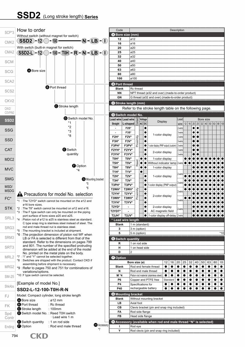
SSD2 (Long stroke length) Series
How to orderWithout switch (without magnet for switch)
With switch (built-in magnet for switch)
Bore sizeA
Stroke lengthC
Switch quantity
E
Option *4
F
Mounting bracket*5*6
G
Accessory *7
H
12
R N
IN100
12 100
D Switch model No. *1*2*3*8
Port threadB
I
Precautions for model No. selection*1 : The T2YD* switch cannot be mounted on the ø12 and
ø16 bore sizes.*2 : The T8* switch cannot be mounted on ø12 and ø16.*3 : The F type switch can only be mounted on the piping
port surface of bore sizes ø20 and ø25.*4 : Piston rod of ø12 to ø25 is stainless steel as standard.
C type snap ring is stainless steel instead of steel. The rod end male thread nut is stainless steel.
*5 : The mounting bracket is included at shipment.*6 : The projection dimension of piston rod WF when
LB or FA is selected is different from that of the standard. Refer to the dimensions on pages 799 and 801. The number of the specified protruding dimension will be added at the end of the model No. printed on the metal plate on the body.
*7 : “I” and “Y” cannot be selected together.*8 : Switches are shipped with the product. Contact CKD if
assembling before shipment is necessary.*9 : Refer to pages 750 and 751 for combinations of
variations/options.*10 : F type switch cannot be selected.
[Example of model No.]SSD2-L-12-100-T0H-R-NModel: Compact cylinder, long stroke lengthA Bore size : ø12 mmB Port thread : Rc threadC Stroke length : 100mmD Switch model No. : Reed T0H switch · Lead wire 1 mE Switch quantity : 1 on rod sideF Option : Rod end male thread
Code DescriptionBore size (mm)
12 ø1216 ø1620 ø2025 ø2532 ø3240 ø4050 ø5063 ø6380 ø80
100 ø100
Port threadBlank Rc thread
NN NPT thread (ø32 and over) (made-to-order product)GN G thread (ø32 and over) (made-to-order product)
Stroke length (mm)Refer to the stroke length table on the following page.
* Lead wire lengthBlank 1 m (standard)
3 3 m (option)5 5 m (option) *10
Switch quantityR 1 on rod sideH 1 on head sideD 2
OptionBore size (ø) 12 16 20 25 32 40 50 63 80 100
Blank Rod end female thread
N Rod end male thread
M *4 Piston rod material (stainless steel)
P6 Copper and PTFE free Standard
P4 Specifications for rechargeable battery
P40
Mounting bracketBlank Without mounting bracket
LB Axial footCB Clevis bracket (pin and snap ring included)FA Rod side flangeFB Head side flange
Accessory (available when rod end male thread “N” is selected)I Rod eyeY Rod clevis (pin and snap ring included)
H
C
G
F
E
B
A
Switch model No.Lead wire Lead wire
Conta
ct VoltageDisplay
Lead wire
Bore sizeStraight L-shaped AC DC 12 16 20 25 32 40 50 63 80 100
- F2S*
Pro
xim
ity
1-color display
2-wire
- F3S* 3-wire
F2H* F2V* 2-wire F3H* F3V* 3-wire
F3PH* F3PV* 1 color display (PNP output) (custom) 3-wire F2YH* F2YV*
2-color display2-wire
F3YH* F3YV* 3-wire T0H* T0V*
Ree
d 1-color display2-wire
T5H* T5V* Without indicator lamp T8H* T8V* 1-color display T1H* T1V*
Pro
xim
ity
1-color display2-wire
T2H* T2V* T3H* T3V*
3-wire
T3PH* T3PV* 1-color display (PNP output) T2WH* T2WV*
2-color display2-wire
T2YH* T2YV* T3WH* T3WV*
3-wire
T3YH* T3YV* T2YD* - 2-color display
AC magnetic field2-wire
T2YDT* - T2JH* T2JV* 1-color display off-delay 2-wire
D
SSD2
SSD2-L
LB
LBT0H
SCP*3
CMK2
CMA2
SCM
SCG
SCA2
SCS2
CKV2
CAV2/COVP/N2
SSD2
SSG
SSD
CAT
MDC2
MVC
SMG
MSD/MSDG
FC*
STK
SRL3
SRG3
SRM3
SRT3
MRL2
MRG2
SM‑25
ShkAbs
FJ
FK
SpdContr
Ending
794

SSD2 (Long stroke length) SeriesHow to order
[Stroke length table]
*1: The total length is the same as that of the next longer standard stroke length.
Stroke length (mm)
Applicable bore sizeø12 ø16 ø20 ø25 ø32 ø40 ø50 ø63 ø80 ø100
Sta
ndar
d st
roke
leng
th
35 40 45 50 75 100 125 150 175 200 250 300
Max. stroke length (mm) 100 200 300
Custom stroke length *1 In 1 mm increments
Cylinder weight tableStroke length (mm) 35 40 45 50 75 100 125 150 175 200 250 300Bore size (mm) No switch Switch No switch Switch No switch Switch No switch Switch No switch Switch No switch Switch No switch Switch No switch Switch No switch Switch No switch Switch No switch Switch No switch Switch
ø12 144 146 153 155 161 163 170 172 212 214 255 257 - - - - - - - - - - - -ø16 179 180 190 191 201 202 212 213 267 268 322 323 - - - - - - - - - - - -ø20 - - - - - - - - 321 326 383 388 446 451 508 513 571 576 633 638 - - - -ø25 - - - - - - - - 412 417 492 497 572 577 652 657 732 737 812 817 972 977 1132 1137ø32 - - - - - - - - - - - - 790 799 897 905 1003 1012 1111 1119 1326 1334 1541 1549ø40 - - - - - - - - - - - - 1000 1016 1133 1148 1265 1281 1398 1413 1663 1678 1928 1943ø50 - - - - - - - - - - - - 1553 1571 1779 1796 2004 2022 2217 2234 2642 2659 3067 3084ø63 - - - - - - - - - - - - 2138 2162 2413 2437 2688 2712 2963 2987 3512 3536 4062 4086ø80 - - - - - - - - - - - - 3478 3505 3911 3937 4343 4370 4776 4802 5640 5666 6505 6531
ø100 - - - - - - - - - - - - 4816 4848 5386 5418 5956 5988 6526 6558 7667 7699 8807 8839
How to order switch
Switch model No. (Item D on page 794)
(the weight of the switches is when there are 2 cylinder switches.)
How to order mounting bracketBore size (mm)
ø12 ø16 ø20 ø25 ø32 ø40 ø50 ø63 ø80 ø100Mounting bracketFoot (LB) SSD2-LB-12 SSD2-LB-16 SSD2-LB-20 SSD2-LB-25 SSD2-LB-32 SSD2-LB-40 SSD2-LB-50 SSD2-LB-63 SSD2-LB-80 SSD2-LB-100Flange (FA/FB) SSD2-FA-12 SSD2-FA-16 SSD2-FA-20 SSD2-FA-25 SSD2-FA-32 SSD2-FA-40 SSD2-FA-50 SSD2-FA-63 SSD2-FA-80 SSD2-FA-100Clevis bracket (CB) SSD2-CB-12 SSD2-CB-16 SSD2-CB-20 SSD2-CB-25 SSD2-CB-32 SSD2-CB-40 SSD2-CB-50 SSD2-CB-63 SSD2-CB-80 SSD2-CB-100*1: The foot mounting bracket is provided as 2 pcs./set.
SW T0H
(Unit: g)
SCP*3
CMK2
CMA2
SCM
SCG
SCA2
SCS2
CKV2
CAV2/COVP/N2
SSD2
SSG
SSD
CAT
MDC2
MVC
SMG
MSD/MSDG
FC*
STK
SRL3
SRG3
SRM3
SRT3
MRL2
MRG2
SM‑25
ShkAbs
FJ
FK
SpdContr
Ending
795

Internal structure and parts list
SSD2 (long stroke length) -L-12, 16 (double acting/single rod/with switch)
SSD2 (Long stroke length) Series
SSD2 (long stroke length) -12, 16 (double acting/single rod)
ø20: Over 100 to 200 mm stroke length ø25: Over 150 to 300 mm stroke length ø32 to ø50: Over 150 to 300 mm stroke length ø63 to ø100: Over 200 to 300 mm stroke length
SSD2 (long stroke length) -L-20 to 100 (double acting/single rod/with switch)
SSD2 (long stroke length) -20 to 100 (double acting/single rod) ø20: Over 100 to 200 mm stroke length
ø25: Over 150 to 300 mm stroke length ø32 to ø50: Over 150 to 300 mm stroke length ø63 to ø100: Over 200 to 300 mm stroke length
No. Part name Material Remarks No. Part name Material Remarks
1 Piston rod ø12 to 25: Stainless steel ø32 to 100: Steel
ø16 to 100Industrial chrome plating 9 Piston Aluminum alloy Chromate
2 C type snap ring Steel Zinc phosphate 10 Piston packing Nitrile rubber
3 Rod metal Special aluminum Chromate 11 Coverø12 to 25: Stainless steel ø32 to 100: Alumite
(*1)ø32 to 100: Aluminum alloy
4 Rod metal gasket Nitrile rubber 12 Bush Oiles drymet ø20 to 100 (*2)
5 Body Aluminum alloy Hard alumite 13 Cushion rubber (R) Urethane rubber
6 Rod packing Nitrile rubber 14 Cushion rubber (H) Urethane rubber
7 Spacer Aluminum alloy ø12 to ø32: Chromate 15 Wear ring Polyacetal resin
8 Magnet Plastic
*1: For ø20 with more than 100 mm stroke length and ø25 with more than 150 mm stroke length, the standard cover material is aluminum alloy with chromate coating noted in remarks.
*2: Material is steel for copper and PTFE free specifications.
Repair parts listSame as SSD2-K Series (double acting/high load). Refer to pages 780 and 781.
1 2 4 53 76 8
13
9
10 15 14 1112
1 2 4 53 76 9
13 10 15 14 11
12 13 10 15 14 11
1 2 4 53 76 8 9
1 2 4 53 76 9
12 13 10 15 14 11
1 2 4 53 76 9
12 13 10 15 14 11
13 10 15 14 11
1 2 4 53 6 7 8 9
SCP*3
CMK2
CMA2
SCM
SCG
SCA2
SCS2
CKV2
CAV2/COVP/N2
SSD2
SSG
SSD
CAT
MDC2
MVC
SMG
MSD/MSDG
FC*
STK
SRL3
SRG3
SRM3
SRT3
MRL2
MRG2
SM‑25
ShkAbs
FJ
FK
SpdContr
Ending
796

M E M OM E M OSCP*3
CMK2
CMA2
SCM
SCG
SCA2
SCS2
CKV2
CAV2/COVP/N2
SSD2
SSG
SSD
CAT
MDC2
MVC
SMG
MSD/MSDG
FC*
STK
SRL3
SRG3
SRM3
SRT3
MRL2
MRG2
SM‑25
ShkAbs
FJ
FK
SpdContr
Ending
797

Dimensions SSD2 (long stroke length) -(L)-12 to 25
* The dimensions are common for types with and without switches.ø12/ø16
ø20/ø25
Code Common dimensions with switchBore size (mm) A *1 B *1 C D *3 EE F FA *6 FB I J *2 K KA KK M MM N WF
ø12 45.5 32 5.5 5.5 M5 25 13(16.5) 4.5 3.5 6.5 spot face depth 3.5 32 M4 depth 7 M3 depth 6 5 6 15.5 13.5ø16 45.5 32 5.5 5.5 M5 29 15(18.5) 4.5 3.5 6.5 spot face depth 3.5 38 M4 depth 7 M4 depth 8 6 8 20 13.5ø20 55.5 41 8 5.5(8) M5 36 18.5(22) 12.5 5.5 9 spot face depth 5.5 47 M6 depth 11 M5 depth 7 8 10 25.5 14.5ø25 59 44 11 6(11) M5 40 20.5(24) 13.5 5.5 9 spot face depth 5.5 51 M6 depth 11 M6 depth 12 10 12 28 15
*1 : To calculate A + stroke length or B + stroke length when using custom stroke length, apply the next longer standard stroke length (instead of the custom stroke length) to the stroke length value.
(Example) If the custom stroke length is 70 mm, apply the standard stroke length 75 mm.*2 : No spot facing J for ø20 with more than 100 mm stroke length and ø25 with more than 150 mm stroke length.*3 : Values in ( ) are for ø20 with more than 100 mm stroke length and ø25 with more than 150 mm stroke length.*4 : Refer to page 1044 for HD and RD dimensions of the 2-color display, off-delay, AC magnetic field tolerant, T1* and T8* switches.*5 : Refer to page 1044 for protruding dimensions of the 2-color display, off-delay, AC magnetic field tolerant, T1* and T8* switches.*6 : Dimensions in ( ) of FA are for the radial lead wire.*7 : For dimensions of individual accessories, refer to pages 1046 to 1049.
Codea’ c’ H kk’ M MM T wf
Bore size (mm)ø12 10.5 9 8 M5 5 6 3.2 13.5
ø16 12 10 10 M6 6 8 3.6 13.5
ø20 14 12 13 M8 8 10 5 14.5
ø25 17.5 15 17 M10×1.25 10 12 6 15
Dimensions of rod end male thread part
· Precautions regarding the switch mounting groove*1: Only F switch is available for the ø20 or ø25 piping port surface.
Switch dimensions
Reed T0H/T0V,T5H/T5V *3
Proximity T2H/T2V,T3H/T3V *3
Proximity T2WH/T2WV,T3WH/T3WV *3
Proximity F2H/F2V, F3H/F3V,F2YH/F2YV, F3YH/F3YV *3
Proximity F2S/F3S
Bore size (mm) HD RD HD RD HD RD HD RD HD RDø12 8.5 5 8.5 5 10.5 6.5ø16 8.5 5 8.5 5 10.5 6.5ø20 6(12.5) 16(10) 6(12.5) 16(10) 7.5(14) 17.5(12) 10(16.5) 20(14.5) 9(15.5) 19(13.5)ø25 5.5(14) 19.5(12) 5.5(14) 19.5(12) 7(15.5) 21(14) 9.5(18) 23.5(16.5) 8.5(17) 22.5(15.5)
Rod end male thread
SSD2 (Long stroke length) Series
a’c’
T
wf
øMM
kk’Width across flats M
Width across flats H
*6
8-JMounting hole
FA
øK
F N
MNF
FB
FA
*6*28-J
Mounting hole
FA
øK
M
NF
FB N F
A + stroke lengthB + stroke lengthWF
øI
RD
øMM
KK
DC2-EE
HD
8-KA
A + stroke lengthB + stroke length
DC 2-EE
8-KARD
KK
øMM
øI
WF
HD
SCP*3
CMK2
CMA2
SCM
SCG
SCA2
SCS2
CKV2
CAV2/COVP/N2
SSD2
SSG
SSD
CAT
MDC2
MVC
SMG
MSD/MSDG
FC*
STK
SRL3
SRG3
SRM3
SRT3
MRL2
MRG2
SM‑25
ShkAbs
FJ
FK
SpdContr
Ending
798

Dimensions with mounting bracket Axial foot (LB) Clevis bracket (CB) SSD2-(L)-12 to 25 -LB SSD2-(L)-12 to 25 -CB
Rod side flange (FA) SSD2-(L)-12 to 25 -FA
Head side flange (FB) SSD2-(L)-12 to 25 -FB
SSD2 (Long stroke length) SeriesDimensions
Code Common dimensions Female threadBore size
(mm) AB AG AH AK AT AU G N TR TS M
ø12 5 29.5 17 12.5 2 8 M4×10 15.5 34 44 4.8ø16 5 33.5 19 13 2 8 M4×10 20 38 48 4.8ø20 7 42 24 15 3.2 9.2 M6×16 25.5 48 62 7.2ø25 7 46 26 16.5 3.2 10.7 M6×16 28 52 66 7.2
Code Common dimensionsBore size
(mm) FD FH FL FM FT N Gø12 4.5 25 45 55 5.5 15.5 M4×12ø16 4.5 30 45 55 5.5 20 M4×12ø20 6.6 39 48 60 8 25.5 M6×16ø25 6.6 42 52 64 8 28 M6×16
Code Common dimensionsBore size
(mm) FD FH FL FM FT N Gø12 4.5 25 45 55 5.5 15.5 M4×12ø16 4.5 30 45 55 5.5 20 M4×12ø20 6.6 39 48 60 8 25.5 M6×16ø25 6.6 42 52 64 8 28 M6×16
Code Female thread Male threadBore size
(mm) WF Without/with switch a’ wf Without/with switchA B A B
ø12 13.5 51 32 10.5 13.5 61.5 32ø16 13.5 51 32 12 13.5 63 32ø20 14.5 63.5 41 14 14.5 77.5 41ø25 15 67 44 17.5 15 84.5 44
Code Male threadBore size
(mm) WF LF Without/with switch a’ wf LF Without/with switchA B LX A B LX
ø12 13.5 19.5 50.3 32 20 10.5 13.5 19.5 60.8 32 20ø16 13.5 19.5 50.3 32 20 12 13.5 19.5 62.3 32 20ø20 14.5 20.5 62.7 41 29 14 14.5 20.5 76.7 41 29ø25 15 22.5 66.2 44 29 17.5 15 22.5 83.7 44 29
Code Female thread Male threadBore size
(mm) WF Without/with switch a’ wf Without/with switchA B A B
ø12 13.5 45.5 32 10.5 13.5 56 32ø16 13.5 45.5 32 12 13.5 57.5 32ø20 14.5 55.5 41 14 14.5 69.5 41ø25 15 59 44 17.5 15 76.5 44
Code Female thread Male threadBore size
(mm) WF Without/with switch a’ wf Without/with switchA B CJ A B CJ
ø12 13.5 65.5 32 59.5 10.5 13.5 76 32 59.5ø16 13.5 66.5 32 60.5 12 13.5 78.5 32 60.5ø20 14.5 82.5 41 73.5 14 14.5 96.5 41 73.5ø25 15 89 44 79 17.5 15 106.5 44 79
Code Common dimensionsBore size
(mm) CA CB CC CD D E G H N UB
ø12 12 5.2 7 5 4 25 M4×12 C1.5 15.5 10 -0.1 -0.3
ø16 15 6.6 8 5 5 29 M4×12 C2 20 12 -0.1 -0.4
ø20 20 8.2 12 8 5 36 M6×16 C4 25.5 16 -0.1 -0.3
ø25 24 10.2 14 10 5 40 M6×16 C5 28 20 -0.1 -0.3
+ 0.3 0
+ 0.2 0
+ 0.2 0
+ 0.2 0
N
AG N
TRTS
AT
AH
4-øAB
WFA + stroke length
B + stroke length M
AUAK
Low head hexagon socket bolt 8-G
LX + stroke lengthLF
A + stroke lengthB + stroke lengtha’ wf
LF
Rod end male thread
N
FM
FH
WF
Mounting bolt 4-GHexagon socket button head bolt
A + stroke lengthB + stroke lengtha’ wf FT
FL
Rod end male thread
A + stroke length
B + stroke length FT N
2-FD
N
WF
A + stroke lengthB + stroke lengtha’ wf
Rod end male thread
A + stroke lengthB + stroke length
H
CJ + stroke lengthMounting bolt 4-G
N
E
E
CBCC
UBD
øCA
CDH10
CJ + stroke length
A + stroke lengthB + stroke length
FM
NFH
N
2-FD
Mounting bolt 4-GHexagon socket button head bolt
Rod end male thread
FT
A + stroke lengthB + stroke length
FTa’ wf
WFFL
SCP*3
CMK2
CMA2
SCM
SCG
SCA2
SCS2
CKV2
CAV2/COVP/N2
SSD2
SSG
SSD
CAT
MDC2
MVC
SMG
MSD/MSDG
FC*
STK
SRL3
SRG3
SRM3
SRT3
MRL2
MRG2
SM‑25
ShkAbs
FJ
FK
SpdContr
Ending
799

SSD2 (Long stroke length) Series
Dimensions SSD2 (long stroke length) -(L)-32 to 100
* The dimensions are common for types with and without switches.
Code Common dimensions with switchBore size (mm) A *1 B *1 C D *3 EE F FA *6 FB G H I J K KA KK M MM N O P V WF
ø32 62.5 45.5 8 8 Rc1/8 45 23(26.5) 20.5 49.5 12.5 5.5 9 spot face depth 5.5 60 M6 depth 11 M8 depth 13 14 16 34 4.5 22 5 17
ø40 72 55 12 8.5(12) Rc1/8 52 26.5(30) 27.5 57 15 5.5 9 spot face depth 5.5 69 M6 depth 11 M8 depth 13 14 16 40 5 28 5 17
ø50 73.5 55.5 10.5 10.5 Rc1/4 64 32.5(36) 28.5 71 18 6.9 11 spot face depth 6.5 86 M8 depth 13 M10 depth 15 17 20 50 7 35 5 18
ø63 75 57 13 11(13) Rc1/4 77 39(42.5) 28.5 84 23 8.7 14 spot face depth 9 103 M10 depth 25 M10 depth 15 17 20 60 7 35 5 18
ø80 86 66 16 13(16) Rc3/8 98 49.5(53) 28.5 104 31 10.5 17.5 spot face depth 11 132 M12 depth 28 M16 depth 21 22 25 77 6 43 5 20
ø100 97.5 75.5 23 15(23) Rc3/8 117 59(62.5) 28.5 123.5 38 10.5 17.5 spot face depth 11 156 M12 depth 28 M20 depth 27 27 30 94 6.5 59 5 22
*1 : To calculate A + stroke length or B + stroke length when using custom stroke length, apply the next longer standard stroke length (instead of the custom stroke length) to the stroke length value. (Example) If the custom stroke length is 121 mm, apply the standard stroke length 125 mm.
*2 : No spot facing J for ø32 to ø50 with more than 150 mm stroke length and ø63 to ø100 with more than 200 mm stroke length.*3 : Values in ( ) are for ø32 to ø50 with more than 150 mm stroke length and ø63 to ø100 with more than 200 mm stroke length.*4 : Refer to page 1044 for HD and RD dimensions of the 2-color display, off-delay, AC magnetic field tolerant, T1* and T8* switches.*5 : Refer to page 1044 for protruding dimensions of the 2-color display, off-delay, AC magnetic field tolerant, T1* and T8* switches.*6 : Dimensions in ( ) of FA are for the radial lead wire.*7 : For dimensions of individual accessories, refer to pages 1046 to 1049.
Dimensions of rod end male thread partCode
a’ c’ H kk’ M MM T wfBore size (mm)
ø32 23.5 20.5 22 M14×1.5 14 16 8 15
ø40 23.5 20.5 22 M14×1.5 14 16 8 15
ø50 28.5 26 27 M18×1.5 17 20 11 15
ø63 28.5 26 27 M18×1.5 17 20 11 15
ø80 35.5 32.5 32 M22×1.5 22 25 13 18
ø100 35.5 32.5 41 M26×1.5 27 30 16 18
Switch dimensions Reed T0H/T0V, T5H/T5V *3 Proximity T2H/T2V, T3H/T3V *3 Proximity T2WH/T2WV, T3WH/T3WV *3Bore size (mm) HD RD HD RD HD RD
ø32 8.5(16) 18(10) 8.5(16) 18(10) 10(17.5) 19.5(12)
ø40 9.5(19) 26.5(16.5) 9.5(19) 26.5(16.5) 11(20.5) 28(18.5)
ø50 10(19) 26(17) 10(19) 26(17) 11.5(20.5) 27.5(19)
ø63 17.5(23) 20(14.5) 17.5(23) 20(14.5) 19(24.5) 21.5(16.5)
ø80 22.5(28) 24(18.5) 22.5(28) 24(18.5) 24(29.5) 25.5(20.5)
ø100 28(33.5) 28(22.5) 28(33.5) 28(22.5) 29.5(35) 29.5(24.5)
Rod end male thread
F
N
H *28-JMounting hole
O
G F FB N
FA*6
MøK
A + stroke length
B + stroke lengthWF
øI
RDøMM
KK
DC 2-EE
HD
8-KA
øP h
9
a’
c’
T
wf
øMMkk’ Width across
flats MWidth across flats H
øP h
9
V
V
SCP*3
CMK2
CMA2
SCM
SCG
SCA2
SCS2
CKV2
CAV2/COVP/N2
SSD2
SSG
SSD
CAT
MDC2
MVC
SMG
MSD/MSDG
FC*
STK
SRL3
SRG3
SRM3
SRT3
MRL2
MRG2
SM‑25
ShkAbs
FJ
FK
SpdContr
Ending
800

Dimensions with mounting bracket Axial foot (LB) Clevis bracket (CB) SSD2-(L)-32 to 100 -LB SSD2-(L)-32 to 100 -CB
Rod side flange (FA) SSD2-(L)-32 to 100 -FA
Head side flange (FB) SSD2-(L)-32 to 100 -FB
Code Common dimensions Female threadBore size
(mm) AB AD AE AG AH AK AT AU G N TR TSø32 7 18.5 13 57 30 17 3.2 11.2 M6×16 34 57 71ø40 7 18 13 64 33 18.2 3.2 11.2 M6×16 40 64 78ø50 9 22 14 78 39 22.7 3.2 14.7 M8×20 50 79 95ø63 11 26 16 91.5 46 25.2 3.2 16.2 M10×25 60 95 113ø80 13 31.5 20.5 114 59 30.5 4.5 19.5 M12×40 77 118 140
ø100 13 35 24 136 71 35.5 6 23 M12×40 94 137 162Code Male threadBore size
(mm) M WF LF Without/with switch a’ wf LF Without/with switchA B LX A B LX
ø32 7.2 17 25 69.7 45.5 29.5 23.5 15 23 91.2 45.5 29.5ø40 7.2 17 25 79.2 55 39 23.5 15 23 100.7 55 39ø50 8.2 18 29.5 81.7 55.5 32.5 28.5 15 26.5 107.2 55.5 32.5ø63 9.2 18 31 84.2 57 31 28.5 15 28 109.7 57 31ø80 11.5 20 35 97.5 66 36 35.5 18 33 131 66 36
ø100 13 22 39 110.5 75.5 41.5 35.5 18 35 142 75.5 41.5
Code Common dimensionsBore size
(mm) FC FD FH FL FM FT N Gø32 34 5.5 48 56 65 8 34 M6×16ø40 40 5.5 54 62 72 8 40 M6×16ø50 50 6.6 67 76 89 9 50 M8×20ø63 60 9 80 92 108 9 60 M10×25ø80 77 11 99 116 134 11 77 M12×40ø100 94 11 117 136 154 11 94 M12×40
Code Female thread Male threadBore size
(mm) WF Without/with switch a’ wf Without/with switchA B A B
ø32 17 62.5 45.5 23.5 15 84 45.5ø40 17 72 55 23.5 15 93.5 55ø50 18 73.5 55.5 28.5 15 99 55.5ø63 18 75 57 28.5 15 100.5 57ø80 20 86 66 35.5 18 119.5 66
ø100 22 97.5 75.5 35.5 18 129 75.5
SSD2 (Long stroke length) SeriesDimensions
Code Common dimensionsBore size
(mm) AC CB CC CD D E G MR N UB
ø32 4.5 18.2 14 10 5 45 M6×16 10 34 36ø40 5 18.2 14 10 6 52 M6×16 10 40 36ø50 6 22.2 20 14 7 64 M8×20 14 50 44ø63 7 22.2 20 14 8 77 M10×25 14 60 44ø80 9 28.2 27 18 10 98 M12×40 18 77 56
ø100 12 32.2 31 22 13 117 M12×40 22 94 64
Code Female thread Male threadBore size
(mm) WF Without/with switch a’ wf Without/with switchA B CJ A B CJ
ø32 17 92.5 45.5 82.5 23.5 15 114 45.5 80.5ø40 17 104 55 94 23.5 15 125.5 55 92ø50 18 115.5 55.5 101.5 28.5 15 141 55.5 98.5ø63 18 119 57 105 28.5 15 144.5 57 102ø80 20 142 66 124 35.5 18 175.5 66 122
ø100 22 164.5 75.5 142.5 35.5 18 196 75.5 138.5
Code Common dimensionsBore size
(mm) FC FD FH FL FM FT N Gø32 34 5.5 48 56 65 8 34 M6×16ø40 40 5.5 54 62 72 8 40 M6×16ø50 50 6.6 67 76 89 9 50 M8×20ø63 60 9 80 92 108 9 60 M10×25ø80 77 11 99 116 134 11 77 M12×40ø100 94 11 117 136 154 11 94 M12×40
Code Female thread Male threadBore size
(mm) WF Without/with switch a’ wf Without/with switchA B A B
ø32 17 70.5 45.5 23.5 15 92 45.5ø40 17 80 55 23.5 15 101.5 55ø50 18 82.5 55.5 28.5 15 108 55.5ø63 18 84 57 28.5 15 109.5 57ø80 20 97 66 35.5 18 130.5 66
ø100 22 108.5 75.5 35.5 18 140 75.5
NTRTS
4-øAB
AD
AE AT A
H
LF
A + stroke lengthRod end male thread
B + stroke lengtha’ wf
LX + stroke length
A + stroke lengthB + stroke length
Low head hexagon socket bolt 4-G
LF
WF
AUAK
M
AG
N
A + stroke lengthRod end male thread
B + stroke lengtha’ wf
A + stroke lengthB + stroke lengthWF
CJ + stroke length
CJ + stroke length
CC
UBD
NE
E
CDH10
Mounting bolt 4-GAC
RMR
Rod end male thread
A + stroke lengthB + stroke length
A + stroke lengthB + stroke lengtha’ wfFT
FT
FH FC
FM
NFL
4-FD
Mounting bolt 4-Gø32 to ø63: Hexagon socket button head boltø80/ø100: Special bolt
WF
FH FC
A + stroke length
Rod end male thread
B + stroke lengtha’ wf
A + stroke lengthB + stroke lengthWF
FT
4-FDFLN
Mounting bolt 4-G
FM
FT
ø32 to ø63: Hexagon socket button head boltø80/ø100: Special bolt
CB + 0.2 0
SCP*3
CMK2
CMA2
SCM
SCG
SCA2
SCS2
CKV2
CAV2/COVP/N2
SSD2
SSG
SSD
CAT
MDC2
MVC
SMG
MSD/MSDG
FC*
STK
SRL3
SRG3
SRM3
SRT3
MRL2
MRG2
SM‑25
ShkAbs
FJ
FK
SpdContr
Ending
801

Compact cylinder single acting/push
SSD2-X SeriesSingle acting/pull/with switch
SSD2-Y Series Bore size: ø12/ø16/ø20/ø25/ø32/ø40/ø50JIS symbol SSD2-X SSD2-Y
Specifications
*1: Do not leave the single acting cylinder pressurized for a long time. If it is left pressurized for long periods, the piston rod may not return due to spring load when the pressure is released. Use the double acting if the cylinder needs to be left pressurized for long periods.
*2: The ø32 bore size with a 5 mm stroke and without a switch has a port size of M5.
Item SSD2-X SSD2-YSSD2-XL (with switch) SSD2-YL (with switch)
Bore size mm ø12 ø16 ø20 ø25 ø32 ø40 ø50Actuation SSD2-X, XL: single acting/push, SSD2-Y, YL: single acting/pullWorking fluid Compressed airMax. working pressure MPa 1.0 (≈150 psi, 10 bar)Min. working pressure MPa 0.2 (≈29 psi, 2 bar) 0.17 (≈25 psi, 1.7 bar) 0.12 (≈17 psi, 1.2 bar)Proof pressure MPa 1.6 (≈230 psi, 16 bar)Ambient temperature °C -10 (14°F) to 60 (140°F) (no freezing)Port size M5 Rc1/8 *2 Rc1/4
Stroke tolerance mm+1.0
0Working piston speed mm/s 50 to 500Cushion NoneLubrication Not required (use turbine oil ISO VG32 if necessary for lubrication)Allowable absorbed energy J 0.004 0.01 0.016 0.021 0.025 0.092 0.1
Stroke length
*1 : When using the type with switch, refer to the table on the right.*2 : Refer to pages 811 and 817 for the min. stroke length with mounting
bracket LB.
Bore size (mm)
Standard stroke length (mm)
Max. stroke length (mm)
Min. stroke length (mm)
ø12
5, 10 10 5
ø16ø20ø25ø32ø40ø50 10, 20 20 10
Min. stroke length with switch (1 or 2 switches)
*1: Less than 10 mm with the 2-color display, off-delay, AC magnetic field proof, T1* or T8* switch is not available.
*2: 5 mm stroke length is available only for the type with 1 on rod side.
Bore size (mm)
T0H/V / T5H/V T2H/V / T3H/V
ø1210 *2
5
ø16ø20
5ø25ø32ø40ø50 10 10
SSD2-X/SSD2-Y spring loadBore size (mm) Stroke length (mm)
SSD2-X SSD2-YWhen stroke length = 0 At full stroke length operation When stroke length = 0 At full stroke length operation
12 5 4 14 3 1010 4 14 3 10
16 5 6 15 4 1910 6 15 4 19
20 5 6 15 5 2710 6 15 5 27
25 5 11 21 10 2910 11 21 10 29
32 5 23 30 20 2910 16 30 20 29
40 5 13 30 20 2910 21 39 20 29
50 10 30 50 24 8320 24 54 24 83
(Unit: N)
SCP*3
CMK2
CMA2
SCM
SCG
SCA2
SCS2
CKV2
CAV2/COVP/N2
SSD2
SSG
SSD
CAT
MDC2
MVC
SMG
MSD/MSDG
FC*
STK
SRL3
SRG3
SRM3
SRT3
MRL2
MRG2
SM‑25
ShkAbs
FJ
FK
SpdContr
Ending
802
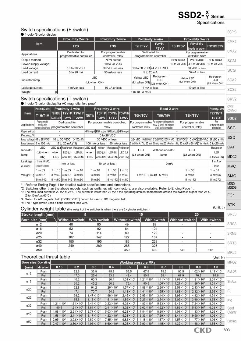
SSD2- SeriesSpecifications
XY
Switch specifications (F switch) 1-color/2-color display
Cylinder weight table (the weight of the switches is when there are 2 cylinder switches.)
Stroke length (mm) 5 10 20Bore size (mm) Without switch With switch Without switch With switch Without switch With switch
ø12 40 80 49 89 - -ø16 52 92 64 104 - -ø20 74 114 89 129 - -ø25 107 147 127 167 - -ø32 155 195 183 223 - -ø40 249 289 285 325 - -ø50 - - 459 499 572 612
(Unit: g)
ItemProximity 2-wire Proximity 3-wire Proximity 2-wire Proximity 3-wire
F2S F3S F2H/F2VF2YH/F2YV
F3H/F3VF3PH/F3PV
(made to order)F3YH/F3YV
Applications Dedicated for programmable controller
For programmable controller, relay
Dedicated for programmable controller
For programmable controller, relay
Output method - NPN output - NPN output PNP output NPN outputPower supply voltage - 10 to 28 VDC - 10 to 28 VDC 4.5 to 28 VDC 10 to 28 VDCLoad voltage 10 to 30 VDC 30 VDC or less 10 to 30 VDC 24 VDC ±10% 30 VDC or lessLoad current 5 to 20 mA 50 mA or less 5 to 20 mA 50 mA or less
Indicator lampLED
(Lit when ON)Yellow LED
(Lit when ON)
Red/greenLED
(Lit when ON)
Yellow LED(Lit when ON)
Red/greenLED
(Lit when ON)
Leakage current 1 mA or less 10 μA or less 1 mA or less 10 μA or lessWeight g 1 m:10 3 m:29
Switch specifications (T switch) 1-color/2-color display/for AC magnetic field proof
ItemProximity 2-wire Proximity 2-wire Proximity 3-wire Reed 2-wire Proximity 2-wire
T1H/T1VT2H/T2V/
T2JH/T2JVT2YH/T2YV
T2WH/ T2WV
T3H/T3VT3PH/T3PV
T3YH/T3YV
T3WH/ T3WV
T0H/T0V T5H/T5V T8H/T8VT2YD(*4)T2YDT
ApplicationsFor programmable
controller, relay, compact solenoid valve
Dedicated for programmable controller
For programmable controller, relay
For programmable controller, relay
For programmable controller, relay, IC circuit (no indicator
lamp), serial connection
For programmable controller, relay
For programmable
controllerOutput method - NPN output PNP output NPN output NPN output -Pwr. supp. V. - 10 to 28 VDC -Load voltage 85 to 265 VAC 10 to 30 VDC 24 VDC ±10% 30 VDC or less 12/24 VDC 100/110 VAC 5/12/24 VDC 100/110 VAC 12/24 VDC 110 VAC 220 VAC 24 VDC ±10%Load current 5 to 100 mA 5 to 20 mA (*3) 100 mA or less 50 mA or less 5 to 50 mA 7 to 20 mA 50 mA or less 20 mA or less 5 to 50 mA 7 to 20 mA 7 to 10 mA 5 to 20 mA
Indicator lamp
LED(Lit when
ON)
LED (Lit when ON)
Red/green LED (Lit
when ON)
Red/green LED (Lit
when ON)
LED (Lit when ON)
Yellow LED (Lit
when ON)
Red/green LED (Lit
when ON)
Red/green LED (Lit
when ON)
LED(Lit when ON)
Without indicator lamp
LED(Lit when ON)
Red/green LED
(Lit when ON)Leakage current
≤ 1 mA at 100 VAC, ≤ 2 mA at 200 VAC
1 mA or less 10 μA or less 0 mA1 mA or
less
Weight g1 m:333 m:875 m:142
1 m:183 m:495 m:80
1 m:333 m:875 m:142
1 m:183 m:495 m:80
1 m:183 m:495 m:80
1 m:333 m:875 m:142
1 m:183 m:495 m:80
1 m:18 3 m:49 5 m:801 m:333 m:875 m:142
1 m:613 m:1665 m:272
*1: Refer to Ending Page 1 for detailed switch specifications and dimensions. *2: Switches other than the above models, such as switches with connectors, are also available. Refer to Ending Page 1. *3: The max. load current is 20 mA at 25°C. The current is lower than 20 mA if the operating ambient temperature around the switch is higher than 25˚C.
(5 to 10 mA at 60°C) *4: Switch for AC magnetic field (T2YD/T2YDT) cannot be used in DC magnetic field. *5: The F type switch uses a bend-resistant lead wire.
Bore size (mm)
Operating direction
Working pressure MPa0.15 0.2 0.3 0.4 0.5 0.6 0.7 0.8 0.9 1.0
ø12Push - 22.6 33.9 45.2 56.5 67.9 79.2 90.5 1.02×10² 1.13×10²
Pull - 17.0 25.4 33.9 42.4 50.9 59.4 67.9 76.3 84.8
ø16Push - 40.2 60.3 80.4 1.01×10² 1.21×10² 1.41×10² 1.61×10² 1.81×10² 2.01×10²
Pull - 30.2 45.2 60.3 75.4 90.5 1.06×10² 1.21×10² 1.36×10² 1.51×10²
ø20Push - 62.8 94.2 1.26×10² 1.57×10² 1.88×10² 2.20×10² 2.51×10² 2.83×10² 3.14×10²
Pull - 47.1 70.7 94.2 1.18×10² 1.41×10² 1.65×10² 1.88×10² 2.12×10² 2.36×10²
ø25Push - 98.2 1.47×10² 1.96×10² 2.45×10² 2.95×10² 3.44×10² 3.93×10² 4.42×10² 4.91×10²
Pull - 75.6 1.13×10² 1.51×10² 1.89×10² 2.27×10² 2.64×10² 3.02×10² 3.40×10² 3.78×10²
ø32Push 1.21×10² 1.61×10² 2.41×10² 3.22×10² 4.02×10² 4.83×10² 5.63×10² 6.43×10² 7.24×10² 8.04×10²
Pull 90.5 1.21×10² 1.81×10² 2.41×10² 3.02×10² 3.62×10² 4.22×10² 4.83×10² 5.43×10² 6.03×10²
ø40Push 1.88×10² 2.51×10² 3.77×10² 5.03×10² 6.28×10² 7.54×10² 8.80×10² 1.01×10³ 1.13×10³ 1.26×10³
Pull 1.58×10² 2.11×10² 3.17×10² 4.22×10² 5.28×10² 6.33×10² 7.39×10² 8.44×10² 9.50×10² 1.06×10³
ø50Push 2.95×10² 3.93×10² 5.89×10² 7.85×10² 9.82×10² 1.18×10³ 1.37×10³ 1.57×10³ 1.77×10³ 1.96×10³
Pull 2.47×10² 3.30×10² 4.95×10² 6.60×10² 8.25×10² 9.90×10² 1.15×10³ 1.32×10³ 1.48×10³ 1.65×10³
Theoretical thrust table (Unit: N)
SCP*3
CMK2
CMA2
SCM
SCG
SCA2
SCS2
CKV2
CAV2/COVP/N2
SSD2
SSG
SSD
CAT
MDC2
MVC
SMG
MSD/MSDG
FC*
STK
SRL3
SRG3
SRM3
SRT3
MRL2
MRG2
SM‑25
ShkAbs
FJ
FK
SpdContr
Ending
803

Model No.A
How to orderWithout switch (without magnet for switch)
With switch (built-in magnet for switch)
SSD2- Series
N I5
Precautions for model No. selection*1 : The T2YD* switch cannot be mounted on the ø12 and
ø16 bore sizes.*2 : The T8* switch cannot be mounted on the ø12 to ø32
bore sizes.*3 : The F switch can only be mounted on the piping port
surface of bore sizes ø20 and ø25.*4 : Piston rod of ø12 to ø25 is stainless steel as standard.
C snap ring is stainless steel instead of steel. The rod end male thread nut is stainless steel.
*5 : The mounting bracket is included at shipment.*6 : The projection dimension of piston rod WF
when LB or FA is selected is different from that of the standard. Refer to the dimensions on pages 809, 811, 813, 815, 817 and 819. The number of the specified protruding dimension will be added at the end of the model No. printed on the metal plate on the body.
*7 : ”I” and “Y” cannot be selected together.*8 : The F switch with L lead wire cannot be selected on
ø20 models.*9 : Switches are shipped with the product. Contact CKD if
assembling before shipment is necessary.*10 : Refer to pages 750 and 751 for combinations of
variations/options.*11 : F type switch cannot be selected.*12 : Refer to pages 811 and 817 for the min. stroke
length with mounting bracket LB.
[Example of model No.]SSD2-XL-12-5-T0H-R-NModel: Compact cylinderA Model No. : Single acting pushB Bore size : ø12 mmC Port thread : Rc threadD Stroke length : 5 mmE Switch model No. : Reed T0H switch/ Lead wire length 1 mF Switch quantity : 1 on rod sideG Option : Rod end male thread
Switch quantityF
Accessory*7
I
Option *4G
XY
Mounting bracket *5*6
H
*1*2*3*8*9
Switch model No.E
Stroke lengthD
Port threadC
Bore sizeB
R N I
SSD2-X 12
12
LB
LBT0H10SSD2-XL
Code DescriptionModel No.
SSD2-X Single acting/pushSSD2-XL Single acting/push/with switch SSD2-Y Single acting/pull
SSD2-YL Single acting/pull/with switch
Bore size (mm)12 ø1216 ø1620 ø2025 ø2532 ø3240 ø4050 ø50
Port threadBlank Rc thread
NN NPT thread (ø32 and over) (made-to-order product)GN G thread (ø32 and over) (made-to-order product)
Stroke length (mm)Bore size (mm) ø12 ø16 ø20 ø25 ø32 ø40 ø50
5 5 10 10 20 20
* Lead wire lengthBlank 1 m (standard)
3 3 m (option)5 5 m (option) *11
Switch quantityR 1 on rod sideH 1 on head sideD 2
OptionBore size (mm) 12 16 20 25 32 40 50
Blank Rod end female thread N Rod end male thread P6 Copper and PTFE free specifications Supported as standard
M *4 Piston rod material (stainless steel) P4 Specifications for rechargeable battery
(Made to order)
P40
Mounting bracketBlank Without mounting bracket
LB Axial footCB Clevis bracket (pin and snap ring included)FA Rod side flangeFB Head side flange
Accessory (available when rod end male thread “N” is selected)I Rod eyeY Rod clevis (pin and snap ring included)
A
B
C
G
H
I
Switch model No.Lead wire Lead wire
Conta
ct VoltageDisplay
Lead wire
Bore sizeStraight L-shaped AC DC 12 16 20 25 32 40 50
- F2S*P
roxi
mity
1-color display
2-wire - F3S* 3-wire
F2H* F2V* 2-wire F3H* F3V* 3-wire
F3PH* F3PV* 1 color display (PNP output) (custom) 3-wire F2YH* F2YV*
2-color display2-wire
F3YH* F3YV* 3-wire T0H* T0V*
Ree
d 1-color display2-wire
T5H* T5V* Without indicator lamp T8H* T8V* 1-color display T1H* T1V*
Pro
xim
ity
1-color display
2-wire
T2H* T2V* T3H* T3V*
3-wire
T3PH* T3PV* 1-color display (PNP output) T2WH* T2WV*
2-color display2-wire
T2YH* T2YV* T3WH* T3WV*
3-wire
T3YH* T3YV* T2YD* - 2-color display
AC magnetic field 2-wire
T2YDT* - T2JH* T2JV* 1-color display off-delay 2-wire
F
D
E
SCP*3
CMK2
CMA2
SCM
SCG
SCA2
SCS2
CKV2
CAV2/COVP/N2
SSD2
SSG
SSD
CAT
MDC2
MVC
SMG
MSD/MSDG
FC*
STK
SRL3
SRG3
SRM3
SRT3
MRL2
MRG2
SM‑25
ShkAbs
FJ
FK
SpdContr
Ending
804
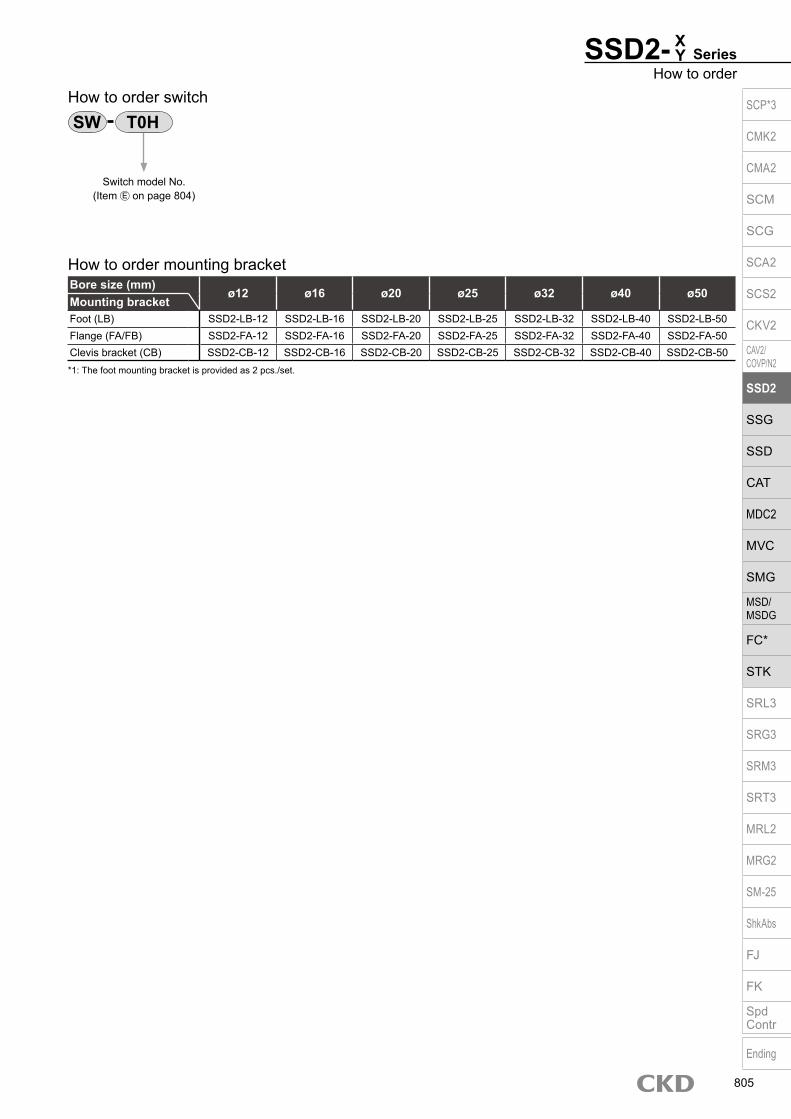
Bore size (mm)ø12 ø16 ø20 ø25 ø32 ø40 ø50
Mounting bracketFoot (LB) SSD2-LB-12 SSD2-LB-16 SSD2-LB-20 SSD2-LB-25 SSD2-LB-32 SSD2-LB-40 SSD2-LB-50Flange (FA/FB) SSD2-FA-12 SSD2-FA-16 SSD2-FA-20 SSD2-FA-25 SSD2-FA-32 SSD2-FA-40 SSD2-FA-50Clevis bracket (CB) SSD2-CB-12 SSD2-CB-16 SSD2-CB-20 SSD2-CB-25 SSD2-CB-32 SSD2-CB-40 SSD2-CB-50
How to order switch
Switch model No. (Item E on page 804)
*1: The foot mounting bracket is provided as 2 pcs./set.
How to order mounting bracket
SSD2- SeriesHow to order
XY
SW T0HSCP*3
CMK2
CMA2
SCM
SCG
SCA2
SCS2
CKV2
CAV2/COVP/N2
SSD2
SSG
SSD
CAT
MDC2
MVC
SMG
MSD/MSDG
FC*
STK
SRL3
SRG3
SRM3
SRT3
MRL2
MRG2
SM‑25
ShkAbs
FJ
FK
SpdContr
Ending
805

SSD2-X Series
Internal structure and parts list SSD2-XL-12 to 32 (single acting/push/with switch) SSD2-XL-40, 50 (single acting/push/with switch)
SSD2-X-12 to 32 (single acting/push) SSD2-X-40, 50 (single acting/push)
No. Part name Material Remarks No. Part name Material Remarks
1 Piston rod ø12 to ø25: Stainless steel ø32 to ø50: Steel
ø16 to ø50: Industrial chrome plating
7 Spacer Aluminum alloy Chromate
8 Magnet Plastic
2 C snap ring Steel Zinc phosphate 9 Piston Aluminum alloy Chromate
3 Rod metal Special aluminum Alumite 10 Piston packing Nitrile rubber
4 Plug Stainless steel11 Cover ø12 to ø25: Stainless steel
ø32 to ø50: Aluminum alloy ø32 to ø50: Alumite5 Body Aluminum alloy Hard alumite
6 Spring Piano wire Electrodeposition 12 Stainless steel wire mesh Stainless steel
Repair parts listBore size (mm) Kit No. Repair parts No.
ø12 SSD2-X-12K
10
ø16 SSD2-X-16Kø20 SSD2-X-20Kø25 SSD2-X-25Kø32 SSD2-X-32Kø40 SSD2-X-40Kø50 SSD2-X-50K
1 2 3 12 4 5 6 7 8 9 10 11
1 2 3 12 4 5 6 9 10 11
1 2 3 12 4 5 6 7 8 9 10 11
1 2 3 12 4 5 6 9 10 11
SCP*3
CMK2
CMA2
SCM
SCG
SCA2
SCS2
CKV2
CAV2/COVP/N2
SSD2
SSG
SSD
CAT
MDC2
MVC
SMG
MSD/MSDG
FC*
STK
SRL3
SRG3
SRM3
SRT3
MRL2
MRG2
SM‑25
ShkAbs
FJ
FK
SpdContr
Ending
806

SSD2-Y SeriesInternal structure and parts list
Internal structure and parts list SSD2-YL (single acting/pull/with switch)
SSD2-Y (single acting/pull)
No. Part name Material Remarks No. Part name Material Remarks
1 Piston Stainless steel8 Magnet Plastic
9 Rod packing Nitrile rubber
2 C snap ring Steel Zinc phosphate 10 Piston packing Nitrile rubber
3 Rod metal Special aluminum alloy Alumite11 Cover ø12 to ø25: Stainless steel
ø32 to ø50: Aluminum alloy ø32 to ø50: Alumite4 Plug Stainless steel
5 Body Aluminum alloy Hard alumite 12 Metal gasket Nitrile rubber
6 Spring Piano wire Electrodeposition 13 Round S type snap ring Steel Zinc phosphate
7 Spacer Aluminum alloy Chromate 14 Stainless steel wire mesh Stainless steel
Repair parts listBore size (mm) Kit No. Repair parts No.
ø12 SSD2-Y-12K
9 10 12
ø16 SSD2-Y-16Kø20 SSD2-Y-20Kø25 SSD2-Y-25Kø32 SSD2-Y-32Kø40 SSD2-Y-40Kø50 SSD2-Y-50K
1 2 3 9 12 13 5 7 8 10 4 14 6 11
1 2 3 9 12 5 10 4 6 14 11
SCP*3
CMK2
CMA2
SCM
SCG
SCA2
SCS2
CKV2
CAV2/COVP/N2
SSD2
SSG
SSD
CAT
MDC2
MVC
SMG
MSD/MSDG
FC*
STK
SRL3
SRG3
SRM3
SRT3
MRL2
MRG2
SM‑25
ShkAbs
FJ
FK
SpdContr
Ending
807

SSD2-X Series
Dimensions SSD2-XL-12 to 25 (with switch)
Codea’ c’ H kk’ M MM T wf
Bore size (mm)ø12 10.5 9 8 M5 5 6 3.2 3.5ø16 12 10 10 M6 6 8 3.6 3.5ø20 14 12 13 M8 8 10 5 4.5ø25 17.5 15 17 M10×1.25 10 12 6 5
Rod end male thread
Switch dimensions
Reed T0H/T0V,T5H/T5V
Proximity T2H/T2V,T3H/T3V
Proximity T2WH/T2WV,T3WH T3WV
Proximity F2H/F2V, F3H/F3V,F2YH/F2YV, F3YH/F3YV
Proximity F2S/F3S
Bore size (mm) HD RD HD RD HD RD HD RD HD RDø12 0 3 0 3 2 5ø16 0 4 0 4.5 1 6ø20 3 7.5 3 7.5 5 9.5 7.5 12 6.5 11ø25 4 9.5 4 9.5 6 11.5 8.5 14 7.5 13
*1 : Only F switch is available for the ø20 or ø25 piping port surface.*2 : HD and RD dimensions for 5 mm stroke length differ from these dimensions according to the setting.*3 : Refer to page 1044 for HD, RD and protruding dimensions of the 2-color display, off-delay, AC magnetic field proof, T1* and T8* switches.*4 : Dimensions in ( ) of FA are for the radial lead wire.*5 : For dimensions of individual accessories, refer to pages 1046 to 1049.
Code Common dimensions with switchBore size (mm) A B C D EE F FA *4 FB I J K KA KK M MM N WF
ø12
Stroke
length 5 30.5 27
5.5 5.5 M5 25 13(16.5) 4.5 3.5 6.5 spot face
depth 3.5 32 M4 depth 7
M3 depth 6 5 6 15.5 3.5
10 35.5 32
ø16
Stroke
length 5 30.5 27
5.5 5.5 M5 29 15(18.5) 4.5 3.5 6.5 spot face
depth 3.5 38 M4 depth 7
M4 depth 8 6 8 20 3.5
10 35.5 32
ø20
Stroke
length 5 39 34.5
8 5.5 M5 36 18.5(22) 12.5 5.5 9 spot face
depth 5.5 47 M6 depth 11
M5 depth 7 8 10 25.5 4.5
10 44 39.5
ø25
Stroke
length 5 42.5 37.5
11 6 M5 40 20.5(24) 13.5 5.5 9 spot face
depth 5.5 51 M6 depth 11
M6 depth 12 10 12 28 5
10 47.5 42.5
Rod end male thread
ø12/ø16
8-JMounting hole
F
N
F N
FB
FA
FB
FA
M
*4
øK
ABWF
Plug(With breathing hole)
KK
C D2-EE
øMM
øI 8-KA
ø20/ø25
8-JMounting hole
FN
F N FB
FAM *4øK
ABWF
Plug(With breathing hole)
KK
C DEE
øMM
øI 8-KA
HD
RD
a’c’
wf
T
kk’
øMM
Width across flats M
Width across flats H
HD
RD
SCP*3
CMK2
CMA2
SCM
SCG
SCA2
SCS2
CKV2
CAV2/COVP/N2
SSD2
SSG
SSD
CAT
MDC2
MVC
SMG
MSD/MSDG
FC*
STK
SRL3
SRG3
SRM3
SRT3
MRL2
MRG2
SM‑25
ShkAbs
FJ
FK
SpdContr
Ending
808
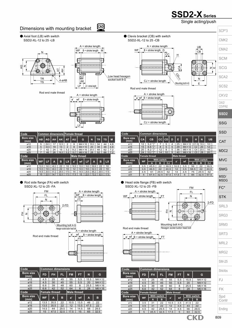
Dimensions with mounting bracket Axial foot (LB) with switch Clevis bracket (CB) with switch SSD2-XL-12 to 25 -LB SSD2-XL-12 to 25 -CB
Rod side flange (FA) with switch SSD2-XL-12 to 25 -FA
Head side flange (FB) with switch SSD2-XL-12 to 25 -FB
Code Common dimensionsBore size
(mm) FD FH FL FM FT N Gø12 4.5 25 45 55 5.5 15.5 M4×12ø16 4.5 30 45 55 5.5 20 M4×12ø20 6.6 39 48 60 8 25.5 M6×16ø25 6.6 42 52 64 8 28 M6×16
Code Female thread Male threadBore size
(mm) WF A B a’ wf A Bø12 13.5 35.5 22 10.5 13.5 46 22ø16 13.5 35.5 22 12 13.5 47.5 22ø20 14.5 44 29.5 14 14.5 58 29.5ø25 15 47.5 32.5 17.5 15 65 32.5
SSD2-X SeriesSingle acting/push
Code Common dimensions Female thread
Code Male threadBore size
(mm) WF LF A B LX a’ wf LF A B LXø12 13.5 19.5 40.3 22 10 10.5 13.5 19.5 50.8 22 10ø16 13.5 19.5 40.3 22 10 12 13.5 19.5 52.3 22 10ø20 14.5 20.5 51.2 29.5 17.5 14 14.5 20.5 65.2 29.5 17.5ø25 15 22.5 54.7 32.5 17.5 17.5 15 22.5 72.2 32.5 17.5
Bore size (mm) AB AG AH AK AT AU G N TR TS M
ø12 5 29.5 17 12.5 2 8 M4×10 15.5 34 44 4.8ø16 5 33.5 19 13 2 8 M4×10 20 38 48 4.8ø20 7 42 24 15 3.2 9.2 M6×16 25.5 48 62 7.2ø25 7 46 26 16.5 3.2 10.7 M6×16 28 52 66 7.2
Code Common dimensionsBore size
(mm) CA CB CC CD D E G H N UBø12 12 5.2 7 5 4 25 M4×12 C1.5 15.5 10ø16 15 6.6 8 5 5 29 M4×12 C2 20 12ø20 20 8.2 12 8 5 36 M6×16 C4 25.5 16ø25 24 10.2 14 10 5 40 M6×16 C5 28 20
+ 0.3 0
+ 0.2 0
+ 0.2 0
+ 0.2 0
-0.1 -0.4
-0.1 -0.3
-0.1 -0.3
-0.1 -0.3
Code Female thread Male thread
Bore size (mm) WF
With switcha’ wf
With switchA B CJ A B CJ
ø12 3.5 45.5 22 39.5 10.5 3.5 56 22 39.5ø16 3.5 46.5 22 40.5 12 3.5 58.5 22 40.5ø20 4.5 61 29.5 52 14 4.5 75 29.5 52ø25 5 67.5 32.5 57.5 17.5 5 85 32.5 57.5
Code Common dimensionsBore size
(mm) FD FH FL FM FT N Gø12 4.5 25 45 55 5.5 15.5 M4×12ø16 4.5 30 45 55 5.5 20 M4×12ø20 6.6 39 48 60 8 25.5 M6×16ø25 6.6 42 52 64 8 28 M6×16
Code Female thread Male threadBore size
(mm) WFWith switch
a’ wfWith switch
A B A Bø12 3.5 31 22 10.5 3.5 41.5 22ø16 3.5 31 22 12 3.5 43 22ø20 4.5 42 29.5 14 4.5 56 29.5ø25 5 45.5 32.5 17.5 5 63 32.5
N
AG N
TRTS
AT
AH
4-øAB
WFA + stroke length
B + stroke length M
AUAK
Low head hexagon socket bolt 8-G
LX + stroke lengthLF
A + stroke lengthB + stroke lengtha’ wf
LF
Rod end male thread
N
FM
FH
WF
Mounting bolt 4-G Hexagon socket button head bolt
A + stroke lengthB + stroke lengtha’ wf FT
FL
Rod end male thread
A + stroke length
B + stroke length FT N
2-FD
N
WF
A + stroke lengthB + stroke lengtha’ wf
Rod end male thread
A + stroke lengthB + stroke length
H
CJ + stroke lengthMounting bolt 4-G
N
E
E
CBCC
UBD
øCA
CDH10
CJ + stroke length
A + stroke lengthB + stroke length
FM
NFH
N
2-FD
Mounting bolt 4-GHexagon socket button head bolt
Rod end male thread
FT
A + stroke lengthB + stroke length
FTa’ wf
WFFL
SCP*3
CMK2
CMA2
SCM
SCG
SCA2
SCS2
CKV2
CAV2/COVP/N2
SSD2
SSG
SSD
CAT
MDC2
MVC
SMG
MSD/MSDG
FC*
STK
SRL3
SRG3
SRM3
SRT3
MRL2
MRG2
SM‑25
ShkAbs
FJ
FK
SpdContr
Ending
809
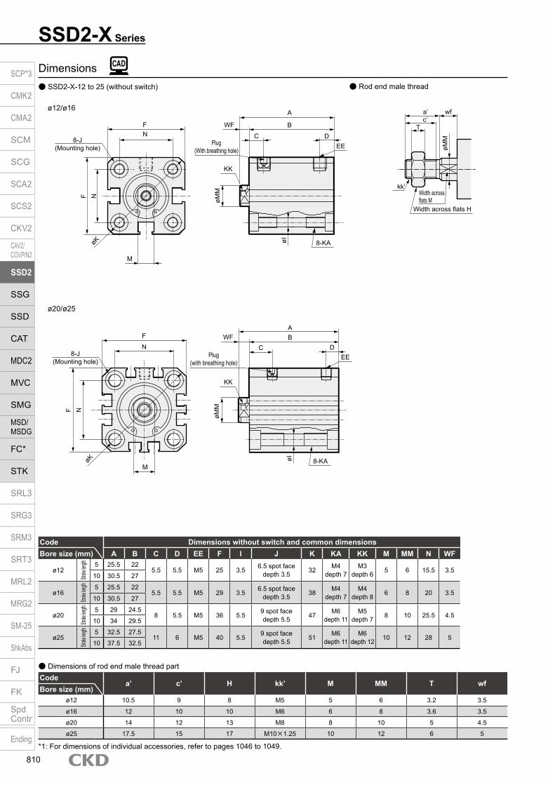
Dimensions SSD2-X-12 to 25 (without switch) Rod end male thread
Code Dimensions without switch and common dimensionsBore size (mm) A B C D EE F I J K KA KK M MM N WF
ø12
Stroke
length 5 25.5 22
5.5 5.5 M5 25 3.5 6.5 spot face depth 3.5 32 M4
depth 7M3
depth 6 5 6 15.5 3.510 30.5 27
ø16
Stroke
length 5 25.5 22
5.5 5.5 M5 29 3.5 6.5 spot face depth 3.5 38 M4
depth 7M4
depth 8 6 8 20 3.510 30.5 27
ø20
Stroke
length 5 29 24.5
8 5.5 M5 36 5.5 9 spot face depth 5.5 47 M6
depth 11M5
depth 7 8 10 25.5 4.510 34 29.5
ø25
Stroke
length 5 32.5 27.511 6 M5 40 5.5 9 spot face
depth 5.5 51 M6 depth 11
M6 depth 12 10 12 28 5
10 37.5 32.5
Codea’ c’ H kk’ M MM T wf
Bore size (mm)ø12 10.5 9 8 M5 5 6 3.2 3.5
ø16 12 10 10 M6 6 8 3.6 3.5
ø20 14 12 13 M8 8 10 5 4.5
ø25 17.5 15 17 M10×1.25 10 12 6 5
Dimensions of rod end male thread part
*1: For dimensions of individual accessories, refer to pages 1046 to 1049.
SSD2-X Series
a’c’
wf
T
kk’
øMM
Width across flats M
Width across flats H
8-J(Mounting hole)
FN
F N
M
øK
ø12/ø16A
BWF
Plug(With breathing hole)
KK
C DEE
øMM
øI 8-KA
ø20/ø25
F
N
F N
MøK
ABWF
Plug (with breathing hole)
KK
C DEE
øMM
øI 8-KA
8-J(Mounting hole)
SCP*3
CMK2
CMA2
SCM
SCG
SCA2
SCS2
CKV2
CAV2/COVP/N2
SSD2
SSG
SSD
CAT
MDC2
MVC
SMG
MSD/MSDG
FC*
STK
SRL3
SRG3
SRM3
SRT3
MRL2
MRG2
SM‑25
ShkAbs
FJ
FK
SpdContr
Ending
810

SSD2-X SeriesSingle acting/push
Dimensions with mounting bracket Axial foot (LB) without switch Clevis bracket (CB) without switch SSD2-X-12 to 25 -LB SSD2-X-12 to 25 -CB
Code Common dimensions Female thread
Code Male thread
Bore size (mm) AB AG AH AK AT AU G N TR TS M
ø12 5 29.5 17 12.5 2 8 M4×10 15.5 34 44 4.8ø16 5 33.5 19 13 2 8 M4×10 20 38 48 4.8ø20 7 42 24 15 3.2 9.2 M6×16 25.5 48 62 7.2ø25 7 46 26 16.5 3.2 10.7 M6×16 28 52 66 7.2
Bore size (mm) WF LF A B LX a’ wf LF A B LX
ø12 13.5 19.5 35.3 17 5 10.5 13.5 19.5 45.8 17 5ø16 13.5 19.5 35.3 17 5 12 13.5 19.5 47.3 17 5ø20 14.5 20.5 41.2 19.5 7.5 14 14.5 20.5 55.2 19.5 7.5ø25 15 22.5 44.7 22.5 7.5 17.5 15 22.5 62.2 22.5 7.5
Rod side flange (FA) without switch SSD2-X-12 to 25 -FA
Head side flange (FB) without switch SSD2-X-12 to 25 -FB
Code Common dimensionsBore size
(mm) FD FH FL FM FT N G
ø12 4.5 25 45 55 5.5 15.5 M4×12ø16 4.5 30 45 55 5.5 20 M4×12ø20 6.6 39 48 60 8 25.5 M6×16ø25 6.6 42 52 64 8 28 M6×16
Code Female thread Male threadBore size
(mm) WF A B a’ wf A B
ø12 13.5 30.5 17 10.5 13.5 41 17ø16 13.5 30.5 17 12 13.5 42.5 17ø20 14.5 34 19.5 14 14.5 48 19.5ø25 15 37.5 22.5 17.5 15 55 22.5
Code Common dimensionsBore size
(mm) CA CB CC CD D E G H N UB
ø12 12 5.2 7 5 4 25 M4×12 C1.5 15.5 10ø16 15 6.6 8 5 5 29 M4×12 C2 20 12ø20 20 8.2 12 8 5 36 M6×16 C4 25.5 16ø25 24 10.2 14 10 5 40 M6×16 C5 28 20
+ 0.3 0
+ 0.2 0
+ 0.2 0
+ 0.2 0
-0.1 -0.4
-0.1 -0.3
-0.1 -0.3
-0.1 -0.3
Code Female thread Male thread
Bore size (mm) WF
Without switcha’ wf
Without switchA B CJ A B CJ
ø12 3.5 40.5 17 34.5 10.5 3.5 51 17 34.5ø16 3.5 41.5 17 35.5 12 3.5 53.5 17 35.5ø20 4.5 51 19.5 42 14 4.5 65 19.5 42ø25 5 57.5 22.5 47.5 17.5 5 75 22.5 47.5
Code Common dimensionsBore size
(mm) FD FH FL FM FT N Gø12 4.5 25 45 55 5.5 15.5 M4×12ø16 4.5 30 45 55 5.5 20 M4×12ø20 6.6 39 48 60 8 25.5 M6×16ø25 6.6 42 52 64 8 28 M6×16
Code Female thread Male threadBore size
(mm) WF Without switch a’ wf Without switchA B A B
ø12 3.5 26 17 10.5 3.5 36.5 17ø16 3.5 26 17 12 3.5 38 17ø20 4.5 32 19.5 14 4.5 46 19.5ø25 5 35.5 22.5 17.5 5 53 22.5
Note: ø20: LB cannot be selected for 5 mm stroke length.
N
AG N
TRTS
AT
AH
4-øAB
WFA + stroke length
B + stroke length M
AUAK
Low head hexagon socket bolt 8-G
LX + stroke lengthLF
A + stroke lengthB + stroke lengtha’ wf
LF
Rod end male thread
N
FM
FH
WF
Mounting bolt 4-GHexagon socket button head bolt
A + stroke lengthB + stroke lengtha’ wf FT
FL
Rod end male thread
A + stroke length
B + stroke length FT N
2-FD
N
WF
A + stroke lengthB + stroke lengtha’ wf
Rod end male thread
A + stroke lengthB + stroke length
H
CJ + stroke lengthMounting bolt 4-G
N
E
E
CBCC
UBD
øCA
CDH10
CJ + stroke length
A + stroke lengthB + stroke length
FM
NFH
N
2-FD
Mounting bolt 4-GHexagon socket button head bolt
Rod end male thread
FT
A + stroke lengthB + stroke length
FTa’ wf
WFFL
SCP*3
CMK2
CMA2
SCM
SCG
SCA2
SCS2
CKV2
CAV2/COVP/N2
SSD2
SSG
SSD
CAT
MDC2
MVC
SMG
MSD/MSDG
FC*
STK
SRL3
SRG3
SRM3
SRT3
MRL2
MRG2
SM‑25
ShkAbs
FJ
FK
SpdContr
Ending
811
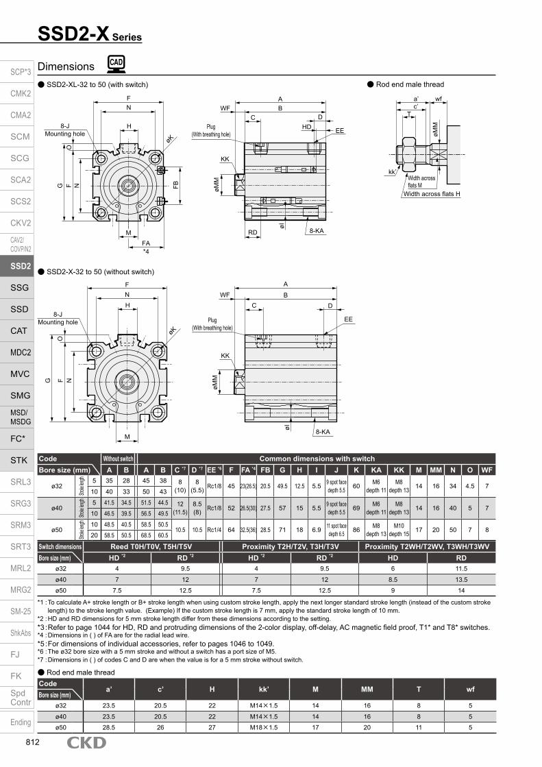
Dimensions SSD2-XL-32 to 50 (with switch)
SSD2-X-32 to 50 (without switch)
Rod end male thread
Switch dimensions Reed T0H/T0V, T5H/T5V Proximity T2H/T2V, T3H/T3V Proximity T2WH/T2WV, T3WH/T3WVBore size (mm) HD *2 RD *2 HD *2 RD *2 HD RD
ø32 4 9.5 4 9.5 6 11.5
ø40 7 12 7 12 8.5 13.5
ø50 7.5 12.5 7.5 12.5 9 14
Codea’ c’ H kk’ M MM T wf
Bore size (mm)ø32 23.5 20.5 22 M14×1.5 14 16 8 5
ø40 23.5 20.5 22 M14×1.5 14 16 8 5
ø50 28.5 26 27 M18×1.5 17 20 11 5
Rod end male thread
*1 : To calculate A+ stroke length or B+ stroke length when using custom stroke length, apply the next longer standard stroke length (instead of the custom stroke length) to the stroke length value. (Example) If the custom stroke length is 7 mm, apply the standard stroke length of 10 mm.
*2 : HD and RD dimensions for 5 mm stroke length differ from these dimensions according to the setting.*3 : Refer to page 1044 for HD, RD and protruding dimensions of the 2-color display, off-delay, AC magnetic field proof, T1* and T8* switches.*4 : Dimensions in ( ) of FA are for the radial lead wire.*5 : For dimensions of individual accessories, refer to pages 1046 to 1049.*6 : The ø32 bore size with a 5 mm stroke and without a switch has a port size of M5.*7 : Dimensions in ( ) of codes C and D are when the value is for a 5 mm stroke without switch.
Code Without switch Common dimensions with switchBore size (mm) A B A B C *7 D *7 EE *6 F FA *4 FB G H I J K KA KK M MM N O WF
ø32
Stroke
length 5 35 28 45 38 8
(10)8
(5.5) Rc1/8 45 23(26.5) 20.5 49.5 12.5 5.5 9 spot face depth 5.5 60 M6
depth 11M8
depth 13 14 16 34 4.5 710 40 33 50 43
ø40
Stroke
length 5 41.5 34.5 51.5 44.5 12
(11.5)8.5(8) Rc1/8 52 26.5(30) 27.5 57 15 5.5 9 spot face
depth 5.5 69 M6 depth 11
M8 depth 13 14 16 40 5 7
10 46.5 39.5 56.5 49.5
ø50
Stroke
length 10 48.5 40.5 58.5 50.5
10.5 10.5 Rc1/4 64 32.5(36) 28.5 71 18 6.9 11 spot face depth 6.5 86 M8
depth 13M10
depth 15 17 20 50 7 820 58.5 50.5 68.5 60.5
SSD2-X Series
a’c’
wf
T
kk’
øMM
Width across flats M
Width across flats H
8-JMounting hole
FN
GO
FB
FA*4
øK
H
F N
ABWF
Plug(With breathing hole)
HDC D
EE
øMM
øI
8-KA
KK
RDM
8-JMounting hole
FN
G
O
øK
H
F N
M
A
BWF
Plug(With breathing hole)
C D
EE
øMM
øI 8-KA
KK
SCP*3
CMK2
CMA2
SCM
SCG
SCA2
SCS2
CKV2
CAV2/COVP/N2
SSD2
SSG
SSD
CAT
MDC2
MVC
SMG
MSD/MSDG
FC*
STK
SRL3
SRG3
SRM3
SRT3
MRL2
MRG2
SM‑25
ShkAbs
FJ
FK
SpdContr
Ending
812

Dimensions with mounting bracket Axial foot (LB) Clevis bracket (CB) SSD2-X(L)-32 to 50 -LB SSD2-X(L)-32 to 50 -CB
Rod side flange (FA) SSD2-X(L)-32 to 50 -FA
Head side flange (FB) SSD2-X(L)-32 to 50 -FB
SSD2-X SeriesSingle acting/push
Code Common dimensions Female thread Bore size
(mm) AB AD AE AG AH AK AT AU G N TR
ø32 7 18.5 13 57 30 17 3.2 11.2 M6×16 34 57ø40 7 18 13 64 33 18.2 3.2 11.2 M6×16 40 64ø50 9 22 14 78 39 22.7 3.2 14.7 M8×20 50 79
CodeBore size
(mm) TS M WF LF Without switch With switchA B LX A B LX
ø32 71 7.2 17 25 47.2(57.2) 23(33) 7(17) 57.2 33 17ø40 78 7.2 17 25 53.7(63.7) 29.5(39.5) 13.5(23.5) 63.7 39.5 23.5ø50 95 8.2 18 29.5 56.7(66.7) 30.5(40.5) 7.5(17.5) 66.7 40.5 17.5
Code Female threadBore size
(mm) WF Without switch With switchA B CJ A B CJ
ø32 7 60 23 50 70 33 60ø40 7 68.5 29.5 58.5 78.5 39.5 68.5ø50 8 80.5 30.5 66.5 90.5 40.5 76.5
Code Male threadBore size
(mm) a’ wf Without switch With switchA B CJ A B CJ
ø32 23.5 5 81.5 23 48 91.5 33 58ø40 23.5 5 90 29.5 56.5 100 39.5 66.5ø50 28.5 5 106 30.5 63.5 116 40.5 73.5
Code Male threadBore size
(mm) a’ wf LF Without switch With switchA B LX A B LX
ø32 23.5 15 23 68.7(78.7) 23(33) 7(17) 78.7 33 17ø40 23.5 15 23 75.2(85.2) 29.5(39.5) 13.5(23.5) 85.2 39.5 23.5ø50 28.5 15 26.5 82.2(92.2) 30.5(40.5) 7.5(17.5) 92.2 40.5 17.5
* Dimensions in ( ) are for stroke lengths of more than 50 mm.
Code Common dimensions
Bore size (mm) FC FD FH FL FM FT N G
ø32 34 5.5 48 56 65 8 34 M6×16ø40 40 5.5 54 62 72 8 40 M6×16ø50 50 6.6 67 76 89 9 50 M8×20
Code Female thread
Bore size (mm) WF Without switch With switch
A B A Bø32 17 40(50) 23(33) 50 33ø40 17 46.5(56.5) 29.5(39.5) 56.5 39.5ø50 18 48.5(58.5) 30.5(40.5) 58.5 40.5
Code Male thread
Bore size (mm) a’ wf Without switch With switch
A B A Bø32 23.5 15 61.5(71.5) 23(33) 71.5 33ø40 23.5 15 68(78) 29.5(39.5) 78 39.5ø50 28.5 15 74(84) 30.5(40.5) 84 40.5
* Dimensions in ( ) are for stroke lengths of more than 50 mm.
Code Common dimensionsBore size
(mm) AC CB CC CD D E G MR N UB
ø32 4.5 18.2 14 10 5 45 M6×16 10 34 36ø40 5 18.2 14 10 6 52 M6×16 10 40 36ø50 6 22.2 20 14 7 64 M8×20 14 50 44
Code Common dimensionsBore size
(mm) FC FD FH FL FM FT N G
ø32 34 5.5 48 56 65 8 34 M6×16ø40 40 5.5 54 62 72 8 40 M6×16ø50 50 6.6 67 76 89 9 50 M8×20
Code Female threadBore size
(mm) WF Without switch With switchA B A B
ø32 7 38 23 48 33ø40 7 44.5 29.5 54.5 39.5ø50 8 47.5 30.5 57.5 40.5
Code Male threadBore size
(mm) a’ wf Without switch With switchA B A B
ø32 23.5 5 59.5 23 69.5 33ø40 23.5 5 66 29.5 76 39.5ø50 28.5 5 73 30.5 83 40.5
NTRTS
4-øAB
AD
AE AT A
H
LF
A + stroke lengthRod end male thread
B + stroke lengtha’ wf
LX + stroke length
A + stroke lengthB + stroke length
Low head hexagon socket bolt 4-G
LF
WF
AUAK
M
AG
N
A + stroke lengthRod end male thread
B + stroke lengtha’ wf
A + stroke lengthB + stroke lengthWF
CJ + stroke length
CJ + stroke length
CC
UBD
NE
E
CDH10
Mounting bolt 4-GAC
RMR
Rod end male thread
A + stroke lengthB + stroke length
A + stroke lengthB + stroke lengtha’ wfFT
FT
FH FC
FM
NFL
4-FD
Mounting bolt 4-Gø32 to ø63: Hexagon socket button head boltø80/ø100: Special bolt
WF
FH FC
A + stroke length
Rod end male thread
B + stroke lengtha’ wf
A + stroke lengthB + stroke lengthWF
FT
4-FDFLN
Mounting bolt 4-G
FM
FT
ø32 to ø63: Hexagon socket button head boltø80/ø100: Special bolt
CB + 0.2 0
SCP*3
CMK2
CMA2
SCM
SCG
SCA2
SCS2
CKV2
CAV2/COVP/N2
SSD2
SSG
SSD
CAT
MDC2
MVC
SMG
MSD/MSDG
FC*
STK
SRL3
SRG3
SRM3
SRT3
MRL2
MRG2
SM‑25
ShkAbs
FJ
FK
SpdContr
Ending
813

Dimensions SSD2-YL-12 to 25 (with switch) Rod end male thread
Codea’ c’ H kk’ M MM T wf
Bore size (mm)ø12 10.5 9 8 M5 5 6 3.2 3.5ø16 12 10 10 M6 6 8 3.6 3.5ø20 14 12 13 M8 8 10 5 4.5ø25 17.5 15 17 M10×1.25 10 12 6 5
Rod end male thread
Switch dimensions
Reed T0H/T0V,T5H/T5V
Proximity T2H/T2V,T3H/T3V
Proximity T2WH/T2WV,T3WH T3WV
Proximity F2H/F2V, F3H/F3V,F2YH/F2YV, F3YH/F3YV
Proximity F2S/F3S
Bore size (mm) HD RD HD RD HD RD HD RD HD RDø12 1.5 1.5 1.5 1.5 3.5 3.5ø16 0 4 0 4.5 1 6ø20 3 7.5 3 7.5 5 9.5 7.5 12 6.5 11ø25 4 9.5 4 9.5 6 11.5 8.5 14 7.5 13
*1 : Only F switch is available for the ø20 or ø25 piping port surface.*2 : HD and RD dimensions for 5 mm stroke length differ from these dimensions according to the setting.*3: Refer to page 1044 for HD, RD and protruding dimensions of the 2-color display, off-delay, AC magnetic field proof, T1* and T8* switches.*4 : Dimensions in ( ) of FA are for the radial lead wire.*5 : For dimensions of individual accessories, refer to pages 1046 to 1049.
Code Common dimensions with switchBore size (mm) A B C D EE F FA *4 FB I J K KA KK M MM N WF
ø12
Stroke
length 5 35.5 27
5.5 5.5 M5 25 13(16.5) 4.5 3.5 6.5 spot face depth 3.5 32 M4
Depth 7M3
Depth 6 5 6 15.5 3.510 45.5 32
ø16
Stroke
length 5 35.5 27
5.5 5.5 M5 29 15(18.5) 4.5 3.5 6.5 spot face depth 3.5 38 M4
Depth 7M4
Depth 8 6 8 20 3.510 45.5 32
ø20
Stroke
length 5 44 34.5
8 5.5 M5 36 18.5(22) 12.5 5.5 9 spot faceDepth 5.5 47 M6
Depth 11M5
Depth 7 8 10 25.5 4.510 54 39.5
ø25
Stroke
length 5 47.5 37.5
11 6 M5 40 20.5(24) 13.5 5.5 9 spot faceDepth 5.5 51 M6
Depth 11M6
Depth 12 10 12 28 510 57.5 42.5
SSD2-Y Series
ø12/ø16
ø20/ø25
8-J(Mounting hole)
FN
F N
MøK
ABWF + stroke length
(at PUSH)
KK
C DEE
øMM
øI 8-KAFB
FA*4
FBFA *4
Plug(With breathing hole)
a’c’
wf + stroke length
T
kk’
øMM
Width across flats M
Width across flats H
FN
F N
MøK
BWF + stroke length(at PUSH)
KK
CEE
øMM
øI 8-KA
FA*4
FB
Plug(With breathing hole)
A
DHD
RD
8-J(Mounting hole)
HD
RD
SCP*3
CMK2
CMA2
SCM
SCG
SCA2
SCS2
CKV2
CAV2/COVP/N2
SSD2
SSG
SSD
CAT
MDC2
MVC
SMG
MSD/MSDG
FC*
STK
SRL3
SRG3
SRM3
SRT3
MRL2
MRG2
SM‑25
ShkAbs
FJ
FK
SpdContr
Ending
814
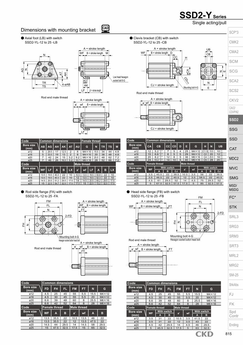
Dimensions with mounting bracket Axial foot (LB) with switch Clevis bracket (CB) with switch SSD2-YL-12 to 25 -LB SSD2-YL-12 to 25 -CB
Rod side flange (FA) with switch SSD2-YL-12 to 25 -FA
Head side flange (FB) with switch SSD2-YL-12 to 25 -FB
Code Common dimensionsBore size
(mm) FD FH FL FM FT N Gø12 4.5 25 45 55 5.5 15.5 M4×12ø16 4.5 30 45 55 5.5 20 M4×12ø20 6.6 39 48 60 8 25.5 M6×16ø25 6.6 42 52 64 8 28 M6×16
Code Female thread Male threadBore size
(mm) WF A B a’ wf A Bø12 13.5 35.5 22 10.5 13.5 46 22ø16 13.5 35.5 22 12 13.5 47.5 22ø20 14.5 44 29.5 14 14.5 58 29.5ø25 15 47.5 32.5 17.5 15 65 32.5
SSD2-Y SeriesSingle acting/pull
Code Common dimensions Female thread
Code Male threadBore size
(mm) WF LF A B LX a’ wf LF A B LXø12 13.5 19.5 40.3 22 10 10.5 13.5 19.5 50.8 22 10ø16 13.5 19.5 40.3 22 10 12 13.5 19.5 52.3 22 10ø20 14.5 20.5 51.2 29.5 17.5 14 14.5 20.5 65.2 29.5 17.5ø25 15 22.5 54.7 32.5 17.5 17.5 15 22.5 72.2 32.5 17.5
Bore size (mm) AB AG AH AK AT AU G N TR TS M
ø12 5 29.5 17 12.5 2 8 M4×10 15.5 34 44 4.8ø16 5 33.5 19 13 2 8 M4×10 20 38 48 4.8ø20 7 42 24 15 3.2 9.2 M6×16 25.5 48 62 7.2ø25 7 46 26 16.5 3.2 10.7 M6×16 28 52 66 7.2
Code Common dimensionsBore size
(mm) CA CB CC CD D E G H N UBø12 12 5.2 7 5 4 25 M4×12 C1.5 15.5 10ø16 15 6.6 8 5 5 29 M4×12 C2 20 12ø20 20 8.2 12 8 5 36 M6×16 C4 25.5 16ø25 24 10.2 14 10 5 40 M6×16 C5 28 20
+ 0.3 0
+ 0.2 0
+ 0.2 0
+ 0.2 0
-0.1 -0.4
-0.1 -0.3
-0.1 -0.3
-0.1 -0.3
Code Female thread Male thread
Bore size (mm) WF
With switcha’ wf
With switchA B CJ A B CJ
ø12 3.5 45.5 22 39.5 10.5 3.5 56 22 39.5ø16 3.5 46.5 22 40.5 12 3.5 58.5 22 40.5ø20 4.5 61 29.5 52 14 4.5 75 29.5 52ø25 5 67.5 32.5 57.5 17.5 5 85 32.5 57.5
Code Common dimensionsBore size
(mm) FD FH FL FM FT N Gø12 4.5 25 45 55 5.5 15.5 M4×12ø16 4.5 30 45 55 5.5 20 M4×12ø20 6.6 39 48 60 8 25.5 M6×16ø25 6.6 42 52 64 8 28 M6×16
Code Female thread Male threadBore size
(mm) WFWith switch
a’ wfWith switch
A B A Bø12 3.5 31 22 10.5 3.5 41.5 22ø16 3.5 31 22 12 3.5 43 22ø20 4.5 42 29.5 14 4.5 46 29.5ø25 5 45.5 32.5 17.5 5 63 32.5
N
AG N
TRTS
AT
AH
4-øAB
WFA + stroke length
B + stroke length M
AUAK
Low head hexagon socket bolt 8-G
LX + stroke lengthLF
A + stroke lengthB + stroke lengtha’ wf
LF
Rod end male thread
N
FM
FH
WF
Mounting bolt 4-GHexagon socket button head bolt
A + stroke lengthB + stroke lengtha’ wf FT
FL
Rod end male thread
A + stroke length
B + stroke length FT N
2-FD
N
WF
A + stroke lengthB + stroke lengtha’ wf
Rod end male thread
A + stroke lengthB + stroke length
H
CJ + stroke lengthMounting bolt 4-G
N
E
E
CBCC
UBD
øCA
CDH10
CJ + stroke length
A + stroke lengthB + stroke length
FM
NFH
N
2-FD
Mounting bolt 4-GHexagon socket button head bolt
Rod end male thread
FT
A + stroke lengthB + stroke length
FTa’ wf
WFFL
SCP*3
CMK2
CMA2
SCM
SCG
SCA2
SCS2
CKV2
CAV2/COVP/N2
SSD2
SSG
SSD
CAT
MDC2
MVC
SMG
MSD/MSDG
FC*
STK
SRL3
SRG3
SRM3
SRT3
MRL2
MRG2
SM‑25
ShkAbs
FJ
FK
SpdContr
Ending
815

Dimensions SSD2-Y-12 to 25 (without switch)
SSD2-Y Series
Code Without switchBore size (mm) A B C D EE F I J K KA KK M MM N WF
ø12
Stroke
length 5 30.5 22
5.5 5.5 M5 25 3.5 6.5 spot face depth 3.5 32 M4
depth 7M3
depth 6 5 6 15.53.5
10 40.5 27 3.5
ø16
Stroke
length 5 30.5 22
5.5 5.5 M5 29 3.5 6.5 spot face depth 3.5 38 M4
depth 7M4
depth 8 6 8 203.5
10 40.5 27 3.5
ø20
Stroke
length 5 34 24.5
8 5.5 M5 36 5.5 9 spot face depth 5.5 47 M6
depth 11M5
depth 7 8 10 25.54.5
10 44 29.5 4.5
ø25
Stroke
length 5 37.5 27.5
11 6 M5 40 5.5 9 spot face depth 5.5 51 M6
depth 11M6
depth 12 10 12 285
10 47.5 32.5 5
Codea’ c’ H kk’ M MM T wf
Bore size (mm)ø12 10.5 9 8 M5 5 6 3.2 3.5
ø16 12 10 10 M6 6 8 3.6 3.5
ø20 14 12 13 M8 8 10 5 4.5
ø25 17.5 15 17 M10×1.25 10 12 6 5
Dimensions of rod end male thread part
*1: For dimensions of individual accessories, refer to pages 1046 to 1049.
Rod end male thread
8-J(Mounting hole)
FN
F N
M
ø12/ø16
ABWF + stroke length
Plug(With breathing hole)KK
C DEE
øMM
øI 8-KA
ø20/ø25
FN
F N
MøK
AB
Plug(With breathing hole)K
C DEE
øMM
øI 8-KA
(at PUSH)
WF + stroke length(at PUSH)
a’c’
wf + stroke length
T
kk’
øMM
Width across flats M
Width across flats H
øK
8-J(Mounting hole)
SCP*3
CMK2
CMA2
SCM
SCG
SCA2
SCS2
CKV2
CAV2/COVP/N2
SSD2
SSG
SSD
CAT
MDC2
MVC
SMG
MSD/MSDG
FC*
STK
SRL3
SRG3
SRM3
SRT3
MRL2
MRG2
SM‑25
ShkAbs
FJ
FK
SpdContr
Ending
816

SSD2-Y SeriesSingle acting/pull
Dimensions with mounting bracket Axial foot (LB) without switch Clevis bracket (CB) without switch SSD2-Y-12 to 25 -LB SSD2-Y-12 to 25 -CB
Code Common dimensions Female thread
Code Male thread
Bore size (mm) AB AG AH AK AT AU G N TR TS M
ø12 5 29.5 17 12.5 2 8 M4×10 15.5 34 44 4.8ø16 5 33.5 19 13 2 8 M4×10 20 38 48 4.8ø20 7 42 24 15 3.2 9.2 M6×16 25.5 48 62 7.2ø25 7 46 26 16.5 3.2 10.7 M6×16 28 52 66 7.2
Bore size (mm) WF LF A B LX a’ wf LF A B LX
ø12 13.5 19.5 35.3 17 5 10.5 13.5 19.5 45.8 17 5ø16 13.5 19.5 35.3 17 5 12 13.5 19.5 47.3 17 5ø20 14.5 20.5 41.2 19.5 7.5 14 14.5 20.5 55.2 19.5 7.5ø25 15 22.5 44.7 22.5 7.5 17.5 15 22.5 62.2 22.5 7.5
Rod side flange (FA) without switch SSD2-Y-12 to 25 -FA
Head side flange (FB) without switch SSD2-Y-12 to 25 -FB
Code Common dimensionsBore size
(mm) FD FH FL FM FT N G
ø12 4.5 25 45 55 5.5 15.5 M4×12ø16 4.5 30 45 55 5.5 20 M4×12ø20 6.6 39 48 60 8 25.5 M6×16ø25 6.6 42 52 64 8 28 M6×16
Code Female thread Male threadBore size
(mm) WF A B a’ wf A B
ø12 13.5 30.5 17 10.5 13.5 41 17ø16 13.5 30.5 17 12 13.5 42.5 17ø20 14.5 34 19.5 14 14.5 48 19.5ø25 15 37.5 22.5 17.5 15 55 22.5
Code Common dimensionsBore size
(mm) CA CB CC CD D E G H N UB
ø12 12 5.2 7 5 4 25 M4×12 C1.5 15.5 10ø16 15 6.6 8 5 5 29 M4×12 C2 20 12ø20 20 8.2 12 8 5 36 M6×16 C4 25.5 16ø25 24 10.2 14 10 5 40 M6×16 C5 28 20
+ 0.3 0
+ 0.2 0
+ 0.2 0
+ 0.2 0
-0.1 -0.4
-0.1 -0.3
-0.1 -0.3
-0.1 -0.3
Code Female thread Male thread
Bore size (mm) WF
Without switcha’ wf
Without switchA B CJ A B CJ
ø12 3.5 40.5 17 34.5 10.5 3.5 51 17 34.5ø16 3.5 41.5 17 35.5 12 3.5 53.5 17 35.5ø20 4.5 51 19.5 42 14 4.5 65 19.5 42ø25 5 57.5 22.5 47.5 17.5 5 75 22.5 47.5
Code Common dimensionsBore size
(mm) FD FH FL FM FT N Gø12 4.5 25 45 55 5.5 15.5 M4×12ø16 4.5 30 45 55 5.5 20 M4×12ø20 6.6 39 48 60 8 25.5 M6×16ø25 6.6 42 52 64 8 28 M6×16
Code Female thread Male threadBore size
(mm) WF Without switch a’ wf Without switchA B A B
ø12 3.5 26 17 10.5 3.5 36.5 17ø16 3.5 26 17 12 3.5 38 17ø20 4.5 32 19.5 14 4.5 46 19.5ø25 5 35.5 22.5 17.5 5 53 22.5
Note: ø20: LB cannot be selected for 5 mm stroke length.
N
AG N
TRTS
AT
AH
4-øAB
WFA + stroke length
B + stroke length M
AUAK
Low head hexagon socket bolt 8-G
LX + stroke lengthLF
A + stroke lengthB + stroke lengtha’ wf
LF
Rod end male thread
N
FM
FH
WF
Mounting bolt 4-GHexagon socket button head bolt
A + stroke lengthB + stroke lengtha’ wf FT
FL
Rod end male thread
A + stroke length
B + stroke length FT N
2-FD
N
WF
A + stroke lengthB + stroke lengtha’ wf
Rod end male thread
A + stroke lengthB + stroke length
H
CJ + stroke lengthMounting bolt 4-G
N
E
E
CBCC
UBD
øCA
CDH10
CJ + stroke length
A + stroke lengthB + stroke length
FM
NFH
N
2-FD
Mounting bolt 4-GHexagon socket button head bolt
Rod end male thread
FT
A + stroke lengthB + stroke length
FTa’ wf
WFFL
SCP*3
CMK2
CMA2
SCM
SCG
SCA2
SCS2
CKV2
CAV2/COVP/N2
SSD2
SSG
SSD
CAT
MDC2
MVC
SMG
MSD/MSDG
FC*
STK
SRL3
SRG3
SRM3
SRT3
MRL2
MRG2
SM‑25
ShkAbs
FJ
FK
SpdContr
Ending
817

Dimensions SSD2-YL-32 to 50 (with switch) Rod end male thread
SSD2-Y-32 to 50 (without switch)
Codea’ c’ H kk’ M MM T wf
Bore size (mm)ø32 23.5 20.5 22 M14×1.5 14 16 8 5
ø40 23.5 20.5 22 M14×1.5 14 16 8 5
ø50 28.5 26 27 M18×1.5 17 20 11 5
Rod end male thread
Switch dimensions Reed T0H/T0V, T5H/T5V Proximity T2H/T2V, T3H/T3V Proximity T2WH/T2WV, T3WH/T3WVBore size (mm) HD *1 RD *1 HD *1 RD *1 HD RD
ø32 4 9.5 4 9.5 6 11.5
ø40 7 12 7 12 8.5 13.5
ø50 7.5 12.5 7.5 12.5 9 14
*1 : HD and RD dimensions for 5 mm stroke length differ from these dimensions according to the setting.*2 : Refer to page 1044 for HD, RD and protruding dimensions of the 2-color display, off-delay, AC magnetic field proof, T1* and T8* switches.*3 : Dimensions in ( ) of FA are for the radial lead wire.*4 : For dimensions of individual accessories, refer to pages 1046 to 1049.*5 : The ø32 bore size with a 5 mm stroke and without a switch has a port size of M5.*6 : Dimensions in ( ) of codes C and D are when the value is for a 5 mm stroke without switch.
Code Without switch Common dimensions with switchBore size (mm) A B A B C *6 D *6 EE *5 F FA *3 FB G H I J K KA KK M MM N O WF
ø32
Stroke
length 5 40 28 50 38 8
(10)8
(5.5) Rc1/8 45 23 (26.5) 20.5 49.5 12.5 5.5 9 spot face
depth 5.5 60 M6Depth 11
M8Depth 13 14 16 34 4.5 7
10 50 33 60 43
ø40
Stroke
length 5 46.5 34.5 56.5 44.5 12
(11.5)8.5(18) Rc1/8 52 26.5
(30) 27.5 57 15 5.5 9 spot face depth 5.5 69 M6
Depth 11M8
Depth 13 14 16 40 5 710 56.5 39.5 66.5 49.5
ø50
Stroke
length 10 58.5 40.5 68.5 50.5
10.5 10.5 Rc1/4 64 32.5 (36) 28.5 71 18 6.9 11 spot face
depth 6.5 86 M8Depth 13
M10Depth 15 17 20 50 7 8
20 78.5 50.5 88.5 60.5
SSD2-Y Series
8-J(Mounting hole)
FN
GO
FB
FA*4
øK
H
F N
M
8-J(Mounting hole)
FN
G
O
øK
H
F N
M
A
B
Plug (with breathing hole)
C D
EE
øMM
øI 8-KA
KK
ABWF + stroke length
(at PUSH)
KK
C D
EE
øMM
øI
8-KA
Plug(With breathing hole)
HD
RD
WF + stroke length(at PUSH)
a’c’
wf + stroke length
T
kk’
øMM
Width across flats M
Width across flats H
SCP*3
CMK2
CMA2
SCM
SCG
SCA2
SCS2
CKV2
CAV2/COVP/N2
SSD2
SSG
SSD
CAT
MDC2
MVC
SMG
MSD/MSDG
FC*
STK
SRL3
SRG3
SRM3
SRT3
MRL2
MRG2
SM‑25
ShkAbs
FJ
FK
SpdContr
Ending
818

Dimensions with mounting bracket Axial foot (LB) Clevis bracket (CB) SSD2-Y(L)-32 to 50 -LB SSD2-Y(L)-32 to 50 -CB
Rod side flange (FA) SSD2-Y(L)-32 to 50 -FA
Head side flange (FB) SSD2-Y(L)-32 to 50 -FB
SSD2-Y SeriesSingle acting/pull
Code Common dimensions Female threadBore size
(mm) AB AD AE AG AH AK AT AU G N TR
ø32 7 18.5 13 57 30 17 3.2 11.2 M6×16 34 57ø40 7 18 13 64 33 18.2 3.2 11.2 M6×16 40 64ø50 9 22 14 78 39 22.7 3.2 14.7 M8×20 50 79
CodeBore size
(mm) TS M WF LF Without switch With switchA B LX A B LX
ø32 71 7.2 17 25 47.2(57.2) 23(33) 7(17) 57.2 33 17ø40 78 7.2 17 25 53.7(63.7) 29.5(39.5) 13.5(23.5) 63.7 39.5 23.5ø50 95 8.2 18 29.5 56.7(66.7) 30.5(40.5) 7.5(17.5) 66.7 40.5 17.5
Code Male threadBore size
(mm) a’ wf LF Without switch With switchA B LX A B LX
ø32 23.5 15 23 68.7(78.7) 23(33) 7(17) 78.7 33 17ø40 23.5 15 23 75.2(85.2) 29.5(39.5) 13.5(23.5) 85.2 39.5 23.5ø50 28.5 15 26.5 82.2(92.2) 30.5(40.5) 7.5(17.5) 92.2 40.5 17.5
* Dimensions in ( ) are for stroke lengths of more than 50 mm.
Code Common dimensions
Bore size (mm) FC FD FH FL FM FT N G
ø32 34 5.5 48 56 65 8 34 M6×16ø40 40 5.5 54 62 72 8 40 M6×16ø50 50 6.6 67 76 89 9 50 M8×20
Code Female thread
Bore size (mm) WF Without switch With switch
A B A Bø32 17 40(50) 23(33) 50 33ø40 17 46.5(56.5) 29.5(39.5) 56.5 39.5ø50 18 48.5(58.5) 30.5(40.5) 58.5 40.5
Code Male thread
Bore size (mm) a’ wf Without switch With switch
A B A Bø32 23.5 15 61.5(71.5) 23(33) 71.5 33ø40 23.5 15 68(78) 29.5(39.5) 78 39.5ø50 28.5 15 74(84) 30.5(40.5) 84 40.5
* Dimensions in ( ) are for stroke lengths of more than 50 mm.
Code Female threadBore size
(mm) WF Without switch With switchA B CJ A B CJ
ø32 7 60 23 50 70 33 60ø40 7 68.5 29.5 58.5 78.5 39.5 68.5ø50 8 80.5 30.5 66.5 90.5 40.5 76.5
Code Male threadBore size
(mm) a’ wf Without switch With switchA B CJ A B CJ
ø32 23.5 5 81.5 23 48 91.5 33 58ø40 23.5 5 90 29.5 56.5 100 39.5 66.5ø50 28.5 5 106 30.5 63.5 116 40.5 73.5
Code Common dimensionsBore size
(mm) AC CB CC CD D E G MR N UBø32 4.5 18.2 14 10 5 45 M6×16 10 34 36ø40 5 18.2 14 10 6 52 M6×16 10 40 36ø50 6 22.2 20 14 7 64 M8×20 14 50 44
Code Common dimensionsBore size
(mm) FC FD FH FL FM FT N G
ø32 34 5.5 48 56 65 8 34 M6×16ø40 40 5.5 54 62 72 8 40 M6×16ø50 50 6.6 67 76 89 9 50 M8×20
Code Female threadBore size
(mm) WF Without switch With switchA B A B
ø32 7 38 23 48 33ø40 7 44.5 29.5 54.5 39.5ø50 8 47.5 30.5 57.5 40.5
Code Male threadBore size
(mm) a’ wf Without switch With switchA B A B
ø32 23.5 5 59.5 23 69.5 33ø40 23.5 5 66 29.5 76 39.5ø50 28.5 5 73 30.5 83 40.5
NTRTS
4-øAB
AD
AE AT A
H
LF
A + stroke lengthRod end male thread
B + stroke lengtha’ wf
LX + stroke length
A + stroke lengthB + stroke length
Low head hexagon socket bolt 4-G
LF
WF
AUAK
M
AG
N
A + stroke lengthRod end male thread
B + stroke lengtha’ wf
A + stroke lengthB + stroke lengthWF
CJ + stroke length
CJ + stroke length
CC
UBD
NE
E
CDH10
Mounting bolt 4-GAC
RMR
Rod end male thread
A + stroke lengthB + stroke length
A + stroke lengthB + stroke lengtha’ wfFT
FT
FH FC
FM
NFL
4-FD
Mounting bolt 4-Gø32 to ø63: Hexagon socket button head boltø80/ø100: Special bolt
WF
FH FC
A + stroke length
Rod end male thread
B + stroke lengtha’ wf
A + stroke lengthB + stroke lengthWF
FT
4-FDFLN
Mounting bolt 4-G
FM
FT
ø32 to ø63: Hexagon socket button head boltø80/ø100: Special bolt
CB + 0.2 0
SCP*3
CMK2
CMA2
SCM
SCG
SCA2
SCS2
CKV2
CAV2/COVP/N2
SSD2
SSG
SSD
CAT
MDC2
MVC
SMG
MSD/MSDG
FC*
STK
SRL3
SRG3
SRM3
SRT3
MRL2
MRG2
SM‑25
ShkAbs
FJ
FK
SpdContr
Ending
819

Compact cylinder double acting/heat resistant
SSD2-T1 Series Bore size: ø12/ø16/ø20/ø25/ø32/ø40/ø50/ø63/ø80/ø100
JIS symbol
Specifications
*1: The ø32 bore size with a 5 mm stroke has a port size of M5.
Item SSD2-T1Bore size mm ø12 ø16 ø20 ø25 ø32 ø40 ø50 ø63 ø80 ø100Actuation Double actingWorking fluid Compressed airMax. working pressure MPa 1.0 (≈150 psi, 10 bar)Min. working pressure MPa 0.1 (≈15 psi, 1 bar) 0.05 (≈7.3 psi, 0.5 bar)Proof pressure MPa 1.6 (≈230 psi, 16 bar)Ambient temperature °C 5 (41°F) to 150 (302°F)Port size M5 Rc1/8 *1 Rc1/4 Rc3/8Stroke tolerance mm +1.0
0
Working piston speed mm/s 50 to 500 50 to 300Cushion NoneLubrication Not availableAllowable absorbed energy J 0.004 0.01 0.016 0.021 0.025 0.092 0.1 0.12 0.27 0.56
*: Refer to pages 763 and 765 for the min. stroke length with mounting bracket LB.
Stroke lengthBore size (mm) Standard stroke length (mm) Max. stroke length (mm) Min. stroke length (mm)
ø12 5/10/15/2025/30
30
1
ø16ø20 5/10/15/20/25
30/35/40/45/5050
ø25ø32 5/10/15/20/25/30/
35/40/45/50/75/100
100
ø40ø50 10/15/20/25
30/35/40/45/5075/100
ø63ø80ø100
Custom stroke length SSD2-T1 Series
ItemStandard products
Standard stroke length body with spacerModel No. Refer to How to order.
DescriptionA spacer is added to the standard stroke length body to adjust the stroke length in 1 mm increments.
Stroke range
Bore size Stroke range12/16 1 to 29
20 to 25 1 to 4932 to 100 1 to 99
Example of model No.Model No.: SSD2-T32-38A +2 mm spacer is added to the SSD2-T32-40 standard cylinder to create 38 mm stroke length. B + stroke length is 63 mm.
Stroke length (mm)5 10 15 20 25 30 35 40 45 50 75 100
Bore size (mm)ø12 36 44 53 61 70 72 - - - - - -ø16 48 59 69 80 91 102 - - - - - -ø20 63 75 88 101 113 126 139 152 165 203 - -ø25 87 102 118 134 150 165 181 197 213 228 - -ø32 122 144 166 188 209 231 253 275 297 318 494 604ø40 183 210 236 263 290 316 342 369 395 472 646 776ø50 - 341 383 425 467 510 552 594 636 678 1025 1235ø63 - 507 562 617 672 727 782 838 893 948 1438 1713ø80 - 928 1015 1101 1188 1274 1361 1448 1535 1621 2401 2833
ø100 - 1433 1547 1660 1774 1888 2002 2115 2229 2343 3406 3973
Cylinder weight table (the weight of the switches is when there are 2 cylinder switches.) (Unit: g)
A + stroke length
B + stroke length
SCP*3
CMK2
CMA2
SCM
SCG
SCA2
SCS2
CKV2
CAV2/COVP/N2
SSD2
SSG
SSD
CAT
MDC2
MVC
SMG
MSD/MSDG
FC*
STK
SRL3
SRG3
SRM3
SRT3
MRL2
MRG2
SM‑25
ShkAbs
FJ
FK
SpdContr
Ending
820

Precautions for model No. selection*1 : Piston rod of ø12 to ø25 is stainless steel as standard.
C snap ring is stainless steel instead of steel. The rod end male thread nut is stainless steel.
*2 : The mounting bracket is included at shipment.*3 : The projection dimension of piston rod WF when
LB or FA is selected is different from that of the standard. Refer to the dimensions on pages 761, 763, 765 and 766. The number of the specified protruding dimension will be added at the end of the model No. printed on the metal plate on the body.
*4 : “I” and “Y” cannot be selected together.*5 : Refer to pages 750 and 751 for combinations of
variations/options.
[Example of model No.]SSD2-T1-12-5-NModel: Compact cylinder, heat resistantA Bore size : ø12 mmB Port thread : Rc threadC Stroke length : 5mmD Option : Rod end male thread
How to order
SSD2-T1 SeriesHow to order
AccessoryF*4
Mounting bracketE*2*3
Option *1D
Stroke lengthC
Port threadB
A Bore size
12 N5 I
Bore size (mm)ø12 ø16 ø20 ø25 ø32 ø40 ø50 ø63 ø80 ø100
Mounting bracketFoot (LB) SSD2-LB-12 SSD2-LB-16 SSD2-LB-20 SSD2-LB-25 SSD2-LB-32 SSD2-LB-40 SSD2-LB-50 SSD2-LB-63 SSD2-LB-80 SSD2-LB-100Flange (FA/FB) SSD2-FA-12 SSD2-FA-16 SSD2-FA-20 SSD2-FA-25 SSD2-FA-32 SSD2-FA-40 SSD2-FA-50 SSD2-FA-63 SSD2-FA-80 SSD2-FA-100Clevis bracket (CB) SSD2-CB-12 SSD2-CB-16 SSD2-CB-20 SSD2-CB-25 SSD2-CB-32 SSD2-CB-40 SSD2-CB-50 SSD2-CB-63 SSD2-CB-80 SSD2-CB-100*1: The foot mounting bracket is provided as 2 pcs./set.
How to order mounting bracket
Code DescriptionBore size (mm)
12 ø1216 ø1620 ø2025 ø2532 ø3240 ø4050 ø5063 ø6380 ø80100 ø100
Port threadBlank Rc thread
NN NPT thread (ø32 and over) (made-to-order product)GN G thread (ø32 and over) (made-to-order product)
Stroke length (mm)
Refer to the stroke length table below.
OptionBlank Rod end female thread
N Rod end male threadM Piston rod material (stainless steel)
Mounting bracketBlank Without mounting bracket
LB Axial footCB Clevis bracket (pin and snap ring included)FA Rod side flangeFB Head side flange
Accessory (available when rod end male thread “N” is selected)I Rod eyeY Rod clevis (pin and snap ring included)
A
B
C
D
F
E
SSD2-T1 LB
*1: The total length when using a custom stroke length is the same as that when using the next longer standard stroke length.
*2: Refer to pages 763 and 765 for the min. stroke length with mounting bracket LB.
[Stroke length table]Stroke length
(mm)Applicable bore size
ø12 ø16 ø20 ø25 ø32 ø40 ø50 ø63 ø80 ø100
Sta
ndar
d st
roke
leng
th
5 10 15 20 25 30 35 40 45 50 75 100
Min. stroke length (mm) 1Max. stroke length (mm) 30 50 100Custom stroke length *1 In 1 mm increments
SCP*3
CMK2
CMA2
SCM
SCG
SCA2
SCS2
CKV2
CAV2/COVP/N2
SSD2
SSG
SSD
CAT
MDC2
MVC
SMG
MSD/MSDG
FC*
STK
SRL3
SRG3
SRM3
SRT3
MRL2
MRG2
SM‑25
ShkAbs
FJ
FK
SpdContr
Ending
821

Internal structure and parts list SSD2-T1-12 to 25
SSD2-T1 Series
SSD2-T1-32 to 50
SSD2-T1-63 to 100
No. Part name Material Remarks7 Piston Aluminum alloy Chromate
8 Piston packing Fluoro rubber
9 Cover ø12 to ø25: Stainless steel ø32 to ø100: Aluminum alloy ø32 to ø100: Alumite
10 Bush Oiles drymet
No. Part name Material Remarks
1 Piston rod ø12 to ø25: Stainless steel ø32 to ø100: Steel
ø16 to ø100:Industrial chrome plating
2 C snap ring Steel Zinc phosphate
3 Rod metal ø12 to ø50: Special aluminumø63 to ø100: Aluminum alloy
ø12 to ø50: Alumite ø63 to ø100: Chromate
4 Rod metal gasket Fluoro rubber
5 Body Aluminum alloy Hard alumite
6 Rod packing Fluoro rubber
Bore size (mm) Kit No. Repair parts No.ø12 SSD2-T-12K
4 6 8
ø16 SSD2-T-16Kø20 SSD2-T-20Kø25 SSD2-T-25Kø32 SSD2-T-32Kø40 SSD2-T-40Kø50 SSD2-T-50Kø63 SSD2-T-63Kø80 SSD2-T-80K
ø100 SSD2-T-100K
Repair parts list
Dimensions
Same as double acting/single rod. Refer to pages 760 to 766.
1 2 3 4 5 6 7 8 9 1 2 3 4 5 6 7 8 9
1 6 2 3 4 10 5 7 8 9
SCP*3
CMK2
CMA2
SCM
SCG
SCA2
SCS2
CKV2
CAV2/COVP/N2
SSD2
SSG
SSD
CAT
MDC2
MVC
SMG
MSD/MSDG
FC*
STK
SRL3
SRG3
SRM3
SRT3
MRL2
MRG2
SM‑25
ShkAbs
FJ
FK
SpdContr
Ending
822

M E M OM E M OSCP*3
CMK2
CMA2
SCM
SCG
SCA2
SCS2
CKV2
CAV2/COVP/N2
SSD2
SSG
SSD
CAT
MDC2
MVC
SMG
MSD/MSDG
FC*
STK
SRL3
SRG3
SRM3
SRT3
MRL2
MRG2
SM‑25
ShkAbs
FJ
FK
SpdContr
Ending
823

Specifications
Stroke length
Note: The custom stroke length is available in 1 mm increments. (Less than 7 mm is not available.) However, the total length is the same as that of the next longer standard stroke length.
Bore size (mm)Standard stroke
length (mm)Max. stroke length
(mm)Min. stroke length (mm)With 1 switch With 2 switches
ø16 10/15/20/25/30 30 10 20ø20 15/20/25/30/
35/40/45/5050 15
25ø25
20ø32
15/20/25/30/35/40/45/50/70/100
100 15ø40ø50ø63
Compact cylinder double acting/with heat resistant cylinder switch
SSD2-T1L Series Bore size: ø16/ø20/ø25/ø32/ø40
ø50/ø63JIS symbol
*1: At an ambient temperature of 150°C, external leakage will occur gradually after approximately 500,000 uses.*2: Periodically apply additional heat-resistant grease.
Item SSD2-T1LBore size mm ø16 ø20 ø25 ø32 ø40 ø50 ø63Actuation Double actingWorking fluid Compressed airMax. working pressure MPa 1.0 (≈150 psi, 10 bar)Min. working pressure MPa 0.1 (≈15 psi, 1 bar) 0.05Proof pressure MPa 1.6 (≈230 psi, 16 bar)Ambient temperature °C 5 (41°F) to 150 (302°F) (*1)Port size M5 Rc1/8 Rc1/4Stroke tolerance mm +1.0
0
Working piston speed mm/s 50 to 500 50 to 300Cushion NoneLubrication (*2) -
Custom stroke length SSD2-T1L Series
ItemStandard products
Standard stroke length body with spacerModel No. Refer to How to order.Description A spacer is added to the standard stroke length body to adjust the stroke length in 1 mm increments.
Stroke range
Bore size Stroke range12/16 1 to 29
20 to 25 1 to 4932 to 63 1 to 99
Example of model No.Model No.: SSD2-T1L-32-38A +2 mm spacer is added to the SSD2-T1L-32-40 standard cylinder to create 38 mm stroke length.B + stroke length is 73 mm.
1 MPa ≈ 145.0 psi, 1 MPa = 10 bar
A + stroke length
B + stroke length
SCP*3
CMK2
CMA2
SCM
SCG
SCA2
SCS2
CKV2
CAV2/COVP/N2
SSD2
SSG
SSD
CAT
MDC2
MVC
SMG
MSD/MSDG
FC*
STK
SRL3
SRG3
SRM3
SRT3
MRL2
MRG2
SM‑25
ShkAbs
FJ
FK
SpdContr
Ending
824

Cylinder switch specifications
ItemReed 2-wireET0H, ET0V
Applications For relay, programmable controllerLoad voltage 12/24 VDC 110 VACLoad current 5 to 50 mA 7 to 20 mAInternal voltage drop 3.0 V or lessLeakage current 0mA
Indicator lampLED
(Lit when ON) (Note)
Lead wireHeat-resistant fluorine-insulated sheathed wire 1 m
(0.5SQ (100/0.08) annealed copper wire x 2C)Insulation resistance 100 MΩ and over with 500 VDC meggerWithstand voltage No failure after 1 minute of 1,000 VAC application.Max. shock resistance 294 m/s2
Ambient temperature -10 to 150°C
Degree of protection IEC standards IP67,JIS C0920 (water-tight)
Weight g 40Note: Indicator uses LED. Visibility will gradually decrease with continuous use under high temperatures. As the LED lamp circuit is separated from the switch output circuit, the switch output works normally even if the LED lamp goes out.
Stroke length (mm) 5 10 15 20 25 30 35 40 45 50 75 100Bore size (mm) No switch Switch No switch Switch No switch Switch No switch Switch No switch Switch No switch Switch No switch Switch No switch Switch No switch Switch No switch Switch No switch Switch No switch Switch
ø16 71 127 82 127 92 137 103 148 114 159 125 170 - - - - - - - - - - - -ø20 63 118 75 150 88 163 101 176 113 188 126 201 139 214 152 227 165 240 203 278 - - - -ø25 87 178 102 193 118 209 134 225 150 241 165 256 181 272 197 288 213 304 228 319 - - - -ø32 122 236 144 258 166 280 188 302 209 323 231 345 253 367 275 389 297 411 318 432 494 542 604 652ø40 183 326 210 353 236 379 263 406 290 433 316 459 342 485 369 512 395 538 472 565 646 695 776 825ø50 - - 341 535 383 577 425 619 467 661 510 704 552 746 594 788 636 830 678 872 1025 1082 1235 1292ø63 - - 507 786 562 841 617 896 672 951 727 1006 782 1061 838 1117 893 1172 948 1227 1438 1502 1713 1777
Cylinder weight table (the weight of the switches is when there are 2 cylinder switches.)
Bore size (mm)
Operating direction
Working pressure MPa0.05 0.1 0.15 0.2 0.3 0.4 0.5 0.6 0.7 0.8 0.9 1.0
ø16Push - 20.1 30.2 40.2 60.3 80.4 1.01×10² 1.21×10² 1.41×10² 1.61×10² 1.81×10² 2.01×10²
Pull - 15.1 22.6 30.2 45.2 60.3 75.4 90.5 1.06×10² 1.21×10² 1.36×10² 1.51×10²
ø20Push - 31.4 47.1 62.8 94.2 1.26×10² 1.57×10² 1.88×10² 2.20×10² 2.51×10² 2.83×10² 3.14×10²
Pull - 23.6 35.3 47.1 70.7 94.2 1.18×10² 1.41×10² 1.65×10² 1.88×10² 2.12×10² 2.36×10²
ø25Push - 49.1 73.6 98.2 1.47×10² 1.96×10² 2.45×10² 2.95×10² 3.44×10² 3.93×10² 4.42×10² 4.91×10²
Pull - 37.8 56.7 75.6 1.13×10² 1.51×10² 1.89×10² 2.27×10² 2.64×10² 3.02×10² 3.40×10² 3.78×10²
ø32Push - 80.4 1.21×10² 1.61×10² 2.41×10² 3.22×10² 4.02×10² 4.83×10² 5.63×10² 6.43×10² 7.24×10² 8.04×10²
Pull - 60.3 90.5 1.21×10² 1.81×10² 2.41×10² 3.02×10² 3.62×10² 4.22×10² 4.83×10² 5.43×10² 6.03×10²
ø40Push - 1.26×10² 1.88×10² 2.51×10² 3.77×10² 5.03×10² 6.28×10² 7.54×10² 8.80×10² 1.01×10³ 1.13×10³ 1.26×10³
Pull - 1.06×10² 1.58×10² 2.11×10² 3.17×10² 4.22×10² 5.28×10² 6.33×10² 7.39×10² 8.44×10² 9.50×10² 1.06×10³
ø50Push - 1.96×10² 2.95×10² 3.93×10² 5.89×10² 7.85×10² 9.82×10² 1.18×10³ 1.37×10³ 1.57×10³ 1.77×10³ 1.96×10³
Pull - 1.65×10² 2.47×10² 3.30×10² 4.95×10² 6.60×10² 8.25×10² 9.90×10² 1.15×10³ 1.32×10³ 1.48×10³ 1.65×10³
ø63Push 1.56×10² 3.12×10² 4.68×10² 6.23×10² 9.35×10² 1.25×10³ 1.56×10³ 1.87×10³ 2.18×10³ 2.49×10³ 2.81×10³ 3.12×10³
Pull 1.40×10² 2.80×10² 4.20×10² 5.61×10² 8.41×10² 1.12×10³ 1.40×10³ 1.68×10³ 1.96×10³ 2.24×10³ 2.52×10³ 2.80×10³
Theoretical thrust table (Unit: N)
(Unit: g)
SSD2-T1L SeriesSpecifications
SCP*3
CMK2
CMA2
SCM
SCG
SCA2
SCS2
CKV2
CAV2/COVP/N2
SSD2
SSG
SSD
CAT
MDC2
MVC
SMG
MSD/MSDG
FC*
STK
SRL3
SRG3
SRM3
SRT3
MRL2
MRG2
SM‑25
ShkAbs
FJ
FK
SpdContr
Ending
825

Mounting bracketG*2*3
Option *1F
A
How to order16
Switch quantityE
Switch model No.D
Stroke lengthC
Port threadB
Bore size
Double acting/heat resistantwith compact heat resistant switch
D N I10
*4AccessoryH
LB
SSD2-T1L Series
SSD2-T1L ET0H
Code DescriptionBore size (mm)
16 ø1620 ø2025 ø2532 ø3240 ø4050 ø5063 ø63
Port threadBlank Rc thread
NN NPT thread (ø32 and over) (made-to-order product)GN G thread (ø32 and over) (made-to-order product)
Stroke length (mm)
Refer to the stroke length table on the following page.
Switch model No.ET0H
Reed AC/DC 2-wireAxial lead wire
ET0V Radial lead wire
Switch quantityR 1 on rod sideH 1 on head sideD 2
OptionBlank Rod end female thread
N Rod end male threadM Piston rod material (stainless steel)
Mounting bracketBlank Without mounting bracket
LB Axial footCB Clevis bracket (pin and snap ring included)FA Rod side flangeFB Head side flange
Accessory (available when rod end male thread “N” is selected)I Rod eyeY Rod clevis (pin and snap ring included)
A
B
C
D
E
F
G
H
Precautions for model No. selection*1 : Piston rod of ø12 to ø25 is stainless steel as
standard. C snap ring is stainless steel instead of steel. The rod end male thread nut is stainless steel.
*2 : The mounting bracket is included at shipment.*3 : The projection dimension of piston rod WF
when LB or FA is selected is different from that of the standard. Refer to the dimensions on pages 830 and 831. The number of the specified protruding dimension will be added at the end of the model No. printed on the metal plate on the body.
*4 : “I” and “Y” cannot be selected together.*5 : Refer to pages 750 and 751 for combinations
of variations/options.*6 : Switches are shipped with the product.
Contact CKD if assembling before shipment is necessary.
[Example of model No.]SSD2-T1L-16-10-ET0H-D-NModel: Compact cylinder
with heat resistant cylinder switchA Bore size : ø16 mmB Port thread : Rc threadC Stroke length : 10mmD Switch model No. : Reed switch ET0H, lead
wire length 1 mE Switch quantity : 2 pcs. includedF Option : Rod end male thread
SCP*3
CMK2
CMA2
SCM
SCG
SCA2
SCS2
CKV2
CAV2/COVP/N2
SSD2
SSG
SSD
CAT
MDC2
MVC
SMG
MSD/MSDG
FC*
STK
SRL3
SRG3
SRM3
SRT3
MRL2
MRG2
SM‑25
ShkAbs
FJ
FK
SpdContr
Ending
826

Bore size (mm)ø16 ø20 ø25 ø32 ø40 ø50 ø63
Mounting bracketFoot (LB) SSD2-LB-16 SSD2-LB-20 SSD2-LB-25 SSD2-LB-32 SSD2-LB-40 SSD2-LB-50 SSD2-LB-63Flange (FA/FB) SSD2-FA-16 SSD2-FA-20 SSD2-FA-25 SSD2-FA-32 SSD2-FA-40 SSD2-FA-50 SSD2-FA-63Clevis bracket (CB) SSD2-CB-16 SSD2-CB-20 SSD2-CB-25 SSD2-CB-32 SSD2-CB-40 SSD2-CB-50 SSD2-CB-63*1: The foot mounting bracket is provided as 2 pcs./set.
How to order mounting bracket
How to order switch
Switch model No. (Item D on page 826)
Stroke length (mm)Applicable bore size
ø16 ø20 ø25 ø32 ø40 ø50 ø63
Sta
ndar
d st
roke
leng
th
10 15 20 25 30 35 40 45 50 70 100
Min. stroke length (mm) 10(20) 15(25) 15(20) 15(20)Max. stroke length (mm) 30 50 100Custom stroke length *2 In 1 mm increments
*1 : The value in ( ) is for types with two switches. Refer to page 824 for the min. stroke length with switch.
*2 : The total length is the same as that of the next longer standard stroke length.
[Stroke length table]SW ET0H
SSD2-T1L SeriesHow to order
SCP*3
CMK2
CMA2
SCM
SCG
SCA2
SCS2
CKV2
CAV2/COVP/N2
SSD2
SSG
SSD
CAT
MDC2
MVC
SMG
MSD/MSDG
FC*
STK
SRL3
SRG3
SRM3
SRT3
MRL2
MRG2
SM‑25
ShkAbs
FJ
FK
SpdContr
Ending
827

SSD2-T1L Series
Internal structure and parts list SSD2-T1L-16 to 25
SSD2-T1L-63
No. Part name Material Remarks No. Part name Material Remarks
1 Piston rod ø16 to ø25: Stainless steelø32 to ø63: Steel
Industrial chrome plating
7 Spacer Aluminum alloy ø32: Chromate
8 Magnet Special alloy
2 C snap ring Steel Zinc phosphate9 Piston ø16 to ø32: Aluminum alloy
ø40 to ø63: Stainless steel ø32: Chromate
3 Rod metal ø16 to ø50: Special aluminumø63: Aluminum alloy
ø16 to ø50: Alumiteø63: Chromate 10 Piston packing Fluoro rubber
4 Rod metal gasket Fluoro rubber11 Cover ø16 to ø25: Stainless steel
ø32 to ø63: Aluminum alloy ø32 to ø100: Alumite5 Body Aluminum alloy Hard alumite
6 Rod packing Fluoro rubber 12 Bush Oiles drymet
Bore size (mm) Kit No. Repair parts No.ø16 SSD2-T-16K
4 6 10
ø20 SSD2-T-20Kø25 SSD2-T-25Kø32 SSD2-T-32Kø40 SSD2-T-40Kø50 SSD2-T-50Kø63 SSD2-T-63K
Repair parts listFluorine grease is used.
SSD2-T1L-32 to 50
1 2 3 4 5 6 7 8 10 9 11
6 21 3 4 12 5 7 8 10 9 11
1 2 3 4 5 6 7 8 10 9 11
SCP*3
CMK2
CMA2
SCM
SCG
SCA2
SCS2
CKV2
CAV2/COVP/N2
SSD2
SSG
SSD
CAT
MDC2
MVC
SMG
MSD/MSDG
FC*
STK
SRL3
SRG3
SRM3
SRT3
MRL2
MRG2
SM‑25
ShkAbs
FJ
FK
SpdContr
Ending
828

Switch dimensions Reed ET0H/ET0VBore size (mm) HD RD
ø16 0.5 0
ø20 0 0
ø25 0 0.5
ø32 0.5 2
ø40 1.5 7
ø50 1.5 6
ø63 5.5 5.5
Codea’ c’ H kk’ M MM T wf
Bore size (mm)ø16 12 10 10 M6 6 8 3.6 3.5
ø20 14 12 13 M8 8 10 5 4.5
ø25 17.5 15 17 M10×1.25 10 12 6 5
ø32 23.5 20.5 22 M14×1.5 14 16 8 5
ø40 23.5 20.5 22 M14×1.5 14 16 8 5
ø50 28.5 26 27 M18×1.5 17 20 11 5
ø63 28.5 26 27 M18×1.5 17 20 11 5
Rod end male thread
*1 : To calculate A+ stroke length or B+ stroke length when using custom stroke length, apply the next longer standard stroke length (instead of the custom stroke length) to the stroke length value. (Example) If the custom stroke length is 7 mm, apply the standard stroke length of 10 mm.
*2 : For dimensions of individual accessories, refer to pages 1046 to 1049.
Code Common dimensions with switchBore size (mm) A *1 B *1 C D EE F FA FB G H I J K KA KK M MM N O WF
ø16 35.5 32 5.5 5.5 M5 29 21 8 - - 3.5 6.5 spot face depth 3.5 38 M4 depth 7 M4 depth 8 6 8 20 - 3.5
ø20 34 29.5 8 5.5 M5 36 24.5 16 - - 5.5 9 spot face depth 5.5 47 M6 depth 11 M5 depth 7 8 10 25.5 - 4.5
ø25 37.5 32.5 11 6 M5 40 26.5 17 - - 5.5 9 spot face depth 5.5 51 M6 depth 11 M6 depth 12 10 12 28 - 5
ø32 40 33 8 8 Rc1/8 45 29 24 49.5 12.5 5.5 9 spot face depth 5.5 60 M6 depth 11 M8 depth 13 14 16 34 4.5 7
ø40 46.5 39.5 12 8.5 Rc1/8 52 32.5 31 57 15 5.5 9 spot face depth 5.5 69 M6 depth 11 M8 depth 13 14 16 40 5 7
ø50 48.5 40.5 10.5 10.5 Rc1/4 64 38.5 32 71 18 6.9 11 spot face depth 6.5 86 M8 depth 13 M10 depth 15 17 20 50 7 8
ø63 54 46 13 11 Rc1/4 77 45 32 84 23 8.7 14 spot face depth 9 103 M10 depth 25 M10 depth 15 17 20 60 7 8
Dimensions SSD2-T1L-16 to 63
SSD2-T1L SeriesDouble acting/with heat resistant cylinder switch
Rod end male thread
· ø16 · ø20 to ø63
a’ wfc’T
kk’
Width across flats HWidth across flats M øM
M
HDD
A + stroke lengthB + stroke length
2-EECWF
øMM
øIRD
FB
FAMøK
G F NO
FNH 8-J
Mounting hole
8-KA
FN
F NøK
FAFBM
FBFA
KK
8-JMounting hole
SCP*3
CMK2
CMA2
SCM
SCG
SCA2
SCS2
CKV2
CAV2/COVP/N2
SSD2
SSG
SSD
CAT
MDC2
MVC
SMG
MSD/MSDG
FC*
STK
SRL3
SRG3
SRM3
SRT3
MRL2
MRG2
SM‑25
ShkAbs
FJ
FK
SpdContr
Ending
829

Dimensions with mounting bracket Axial foot (LB) with switch Clevis bracket (CB) with switch SSD2-T1L-16 to 25 -LB SSD2-T1L-16 to 25 -CB
Rod side flange (FA) with switch SSD2-T1L-16 to 25 -FA
Head side flange (FB) with switch SSD2-T1L-16 to 25 -FB
Code Common dimensionsBore size
(mm) FD FH FL FM FT N Gø16 4.5 30 45 55 5.5 20 M4×12ø20 6.6 39 48 60 8 25.5 M6×16ø25 6.6 42 52 64 8 28 M6×16
Code Female thread Male threadBore size
(mm) WF A B a’ wf A Bø16 13.5 45.5 32 12 13.5 57.5 32ø20 14.5 44 29.5 14 14.5 58 29.5ø25 15 47.5 32.5 17.5 15 65 32.5
Code Common dimensions Female thread
Code Male threadBore size
(mm) WF LF A B LX a’ wf LF A B LX
ø16 13.5 19.5 50.3 32 20 12 13.5 19.5 62.3 32 20ø20 14.5 20.5 51.2 29.5 17.5 14 14.5 20.5 65.2 29.5 17.5ø25 15 22.5 54.7 32.5 17.5 17.5 15 22.5 72.2 32.5 17.5
Bore size (mm) AB AG AH AK AT AU G N TR TS M
ø16 5 33.5 19 13 2 8 M4×10 20 38 48 4.8ø20 7 42 24 15 3.2 9.2 M6×16 25.5 48 62 7.2ø25 7 46 26 16.5 3.2 10.7 M6×16 28 52 66 7.2
SSD2-T1L Series
Code Common dimensionsBore size
(mm) CA CB CC CD D E G H N UBø16 15 6.6 8 5 5 29 M4×12 C2 20 12 -0.1
-0.4
ø20 20 8.2 12 8 5 36 M6×16 C4 25.5 16 -0.1-0.3
ø25 24 10.2 14 10 5 40 M6×16 C5 28 20 -0.1-0.3
+ 0.3 0
+ 0.2 0
+ 0.2 0
Code Female thread Male threadBore size
(mm) WF A B CJ a’ wf A B CJ
ø16 3.5 56.5 32 50.5 12 3.5 68.5 32 50.5ø20 4.5 61 29.5 52 14 4.5 75 29.5 52ø25 5 67.5 32.5 57.5 17.5 5 85 32.5 57.5
Code Common dimensionsBore size
(mm) FD FH FL FM FT N Gø16 4.5 30 45 55 5.5 20 M4×12ø20 6.6 39 48 60 8 25.5 M6×16ø25 6.6 42 52 64 8 28 M6×16
Code Female thread Male threadBore size
(mm) WF A B a’ wf A B
ø16 3.5 41 32 12 3.5 53 32ø20 4.5 42 29.5 14 4.5 56 29.5ø25 5 45.5 32.5 17.5 5 63 32.5
N
AG N
TRTS
AT
AH
4-øAB
WFA + stroke length
B + stroke length M
AUAK
Low head hexagon socket bolt 8-G
LX + stroke lengthLF
A + stroke lengthB + stroke lengtha’ wf
LF
Rod end male thread
N
FM
FH
WF
Mounting bolt 4-GHexagon socket button head bolt
A + stroke lengthB + stroke lengtha’ wf FT
FL
Rod end male thread
A + stroke length
B + stroke length FT N
2-FDN
WF
A + stroke lengthB + stroke lengtha’ wf
Rod end male thread
A + stroke lengthB + stroke length
H
CJ + stroke lengthMounting bolt 4-G
N
E
E
CBCC
UBD
øCA
CDH10
CJ + stroke length
A + stroke lengthB + stroke length
FM
NFH
N
2-FD
Mounting bolt 4-GHexagon socket button head bolt
Rod end male thread
FT
A + stroke lengthB + stroke length
FTa’ wf
WFFL
SCP*3
CMK2
CMA2
SCM
SCG
SCA2
SCS2
CKV2
CAV2/COVP/N2
SSD2
SSG
SSD
CAT
MDC2
MVC
SMG
MSD/MSDG
FC*
STK
SRL3
SRG3
SRM3
SRT3
MRL2
MRG2
SM‑25
ShkAbs
FJ
FK
SpdContr
Ending
830

Dimensions with mounting bracket Axial foot (LB) Clevis bracket (CB) SSD2-T1L -32 to 63 -LB SSD2-T1L -32 to 63 -CB
Rod side flange (FA) SSD2-T1L -32 to 50 -FA
Head side flange (FB) SSD2-T1L -32 to 50 -FB
Code Common dimensions Female threadBore size
(mm) AB AD AE AG AH AK AT AU G N TR TS
ø32 7 18.5 13 57 30 17 3.2 11.2 M6×16 34 57 71ø40 7 18 13 64 33 18.2 3.2 11.2 M6×16 40 64 78ø50 9 22 14 78 39 22.7 3.2 14.7 M8×20 50 79 95ø63 11 26 16 91.5 46 25.2 3.2 16.2 M10×25 60 95 113
* Dimensions in ( ) are for stroke lengths of more than 50 mm.
Code Common dimensionsBore size
(mm) FC FD FH FL FM FT N Gø32 34 5.5 48 56 65 8 34 M6×16ø40 40 5.5 54 62 72 8 40 M6×16ø50 50 6.6 67 76 89 9 50 M8×20ø63 60 9 80 92 108 9 60 M10×25
Code Female thread Male threadBore size
(mm) WF A B a’ wf A Bø32 17 50 33 23.5 15 71.5 33ø40 17 56.5 39.5 23.5 15 78 39.5ø50 18 58.5 40.5 28.5 15 84 40.5ø63 18 64 46 28.5 15 89.5 46
* Dimensions in ( ) are for stroke lengths of more than 50 mm.
SSD2-T1L SeriesDouble acting/with heat resistant cylinder switch
Code Female thread Male threadBore size
(mm) WF A B a’ wf A Bø32 7 48 33 23.5 5 69.5 33ø40 7 54.5 39.5 23.5 5 76 39.5ø50 8 57.5 40.5 28.5 5 83 40.5ø63 8 63 46 28.5 5 88.5 46
Code Male threadBore size
(mm) M WF LF A B LX a’ wf LF A B LX
ø32 7.2 17 25 57.2 33 17 23.5 15 23 78.7 33 17ø40 7.2 17 25 63.7 39.5 23.5 23.5 15 23 85.2 39.5 23.5ø50 8.2 18 29.5 66.7 40.5 17.5 28.5 15 26.5 92.2 40.5 17.5ø63 9.2 18 31 73.2 46 20 28.5 15 28 98.7 46 20
Code Common dimensionsBore size
(mm) AC CB CC CD D E G MR N UB
ø32 4.5 18.2 14 10 5 45 M6×16 10 34 36ø40 5 18.2 14 10 6 52 M6×16 10 40 36ø50 6 22.2 20 14 7 64 M8×20 14 50 44ø63 7 22.2 20 14 8 77 M10×25 14 60 44
Code Common dimensionsBore size
(mm) FC FD FH FL FM FT N Gø32 34 5.5 48 56 65 8 34 M6×16ø40 40 5.5 54 62 72 8 40 M6×16ø50 50 6.6 67 76 89 9 50 M8×20ø63 60 9 80 92 108 9 60 M10×25
Code Female thread Male threadBore size
(mm) WF A B CJ a’ wf A B CJ
ø32 7 70 33 60 23.5 5 91.5 33 58ø40 7 78.5 39.5 68.5 23.5 5 100 39.5 66.5ø50 8 90.5 40.5 76.5 28.5 5 116 40.5 73.5ø63 8 98 46 84 28.5 5 123.5 46 81
NTRTS
4-øAB
AD
AE AT A
H
LF
A + stroke lengthRod end male thread
B + stroke lengtha’ wf
LX + stroke length
A + stroke lengthB + stroke length
Low head hexagon socket bolt 4-G
LF
WF
AUAK
M
AG
N
A + stroke lengthRod end male thread
B + stroke lengtha’ wf
A + stroke lengthB + stroke lengthWF
CJ + stroke length
CJ + stroke length
CC
UBD
NE
E
CDH10
Mounting bolt 4-GAC
RMR
Rod end male thread
A + stroke lengthB + stroke length
A + stroke lengthB + stroke lengtha’ wfFT
FT
FH FC
FM
NFL
4-FD
Mounting bolt 4-Gø32 to ø63: Hexagon socket button head boltø80/ø100: Special bolt
WF
FH FC
A + stroke length
Rod end male thread
B + stroke lengtha’ wf
A + stroke lengthB + stroke lengthWF
FT
4-FDFLN
Mounting bolt 4-G
FM
FT
ø32 to ø63: Hexagon socket button head boltø80/ø100: Special bolt
CB + 0.2 0
SCP*3
CMK2
CMA2
SCM
SCG
SCA2
SCS2
CKV2
CAV2/COVP/N2
SSD2
SSG
SSD
CAT
MDC2
MVC
SMG
MSD/MSDG
FC*
STK
SRL3
SRG3
SRM3
SRT3
MRL2
MRG2
SM‑25
ShkAbs
FJ
FK
SpdContr
Ending
831

Compact cylinder high load/rubber-air cushioned
SSD2-K-*C Series Bore size: ø20/ø25/ø32/ø40/ø50/ø63/ø80/ø100
JIS symbol
When pulledAn airtight space is created in the area when the piston operates and the rubber-air cushion and cover makecontact. Air in the airtight area is further compressed, absorbing energy as the piston operates.At the end of the stroke, energy generated by compression distortion of the rubber cushion is also added.
SpecificationsItem SSD-K-*C
SSD-KL-*C (with switch)Bore size mm ø20 ø25 ø32 ø40 ø50 ø63 ø80 ø100Actuation Double actingWorking fluid Compressed airMax. working pressure MPa 1.0 (≈150 psi, 10 bar)Min. working pressure MPa 0.25 (≈36 psi, 2.5 bar) 0.2 (≈29 psi, 2 bar)Proof pressure MPa 1.6 (≈230 psi, 16 bar)Ambient temperature °C -10 (14°F) to 60 (140°F) (no freezing)Port size Rc1/8 Rc1/4 Rc3/8Stroke tolerance mm +2.0
0
Working piston speed mm/s 50 to 500 50 to 300Cushion Rubber-air cushionLubrication Not required (use turbine oil ISO VG32 if necessary for lubrication)Allowable absorbed energy J 0.16 0.16 0.40 0.63 0.98 1.56 2.51 3.92
Stroke lengthBore size
(mm)Standard stroke length
(mm)Max. stroke length
(mm)Min. stroke length
(mm)ø20 5/10/15/20/25/30/
35/40/45/5050
5ø25ø32 5/10/15/20/25/30/
35/40/45/50/75/100
100
ø40ø50
10/15/20/25/30/35/ 40/45/50/75/100
ø6310ø80
ø100*1 : The custom stroke length is available in 1 mm increments. However, the total length is the
same as that of the next longer standard stroke length.*2 : Refer to page 789 for the min. stroke length with mounting bracket LB.
Min. stroke length with switch (2 switches)
*1: Less than 10 mm with the 2-color display, off-delay, AC magnetic field proof, T1* or T8* switch is not available.
Bore size(mm)
T0H/V / T5H/V T2H/V / T3H/V
ø20
5
5ø25ø32ø40ø50ø63
10ø80ø100
Rubber-air cushion mechanism
Custom stroke length SSD2-K-*C Series
ItemStandard products
Standard stroke length body with spacerModel No. Refer to How to order.
DescriptionA spacer is added to the standard stroke length body to adjust the stroke length in 1 mm increments.
Stroke rangeBore size Stroke range20 to 25 1 to 49
32 to 100 1 to 99
Example of model No.Model No.: SSD2-K-32C-38A +2 mm spacer is added to the SSD2-K-32C-40 standard cylinder to create 38 mm stroke length. B + stroke length is 73 mm.
Rubber-air cushion
Cover
Rubber-air cushion
Cover
Cylinder with rubber cushionCylinder with rubber-air cushion
Data of the reduction of collision noise level (an example case)
Col
lisio
n no
ise le
vel (d
B(A)
)
Kinetic energy (J)0
40
50
60
70
80
0.5 1 1.5
Kinetic energy (J)0 0.5 1 1.5 20
10
20
Col
lisio
n ac
cele
ratio
n (G
)
Data of the reduction of collision acceleration level (an example case)
When V = 300mm/s
When V = 100mm/s
A + stroke lengthB + stroke length
SCP*3
CMK2
CMA2
SCM
SCG
SCA2
SCS2
CKV2
CAV2/COVP/N2
SSD2
SSG
SSD
CAT
MDC2
MVC
SMG
MSD/MSDG
FC*
STK
SRL3
SRG3
SRM3
SRT3
MRL2
MRG2
SM‑25
ShkAbs
FJ
FK
SpdContr
Ending
832

SSD2-K-*C SeriesSpecifications
Switch specifications (F switch) 1-color/2-color display
ItemProximity 2-wire Proximity 3-wire Proximity 2-wire Proximity 3-wire
F2S F3S F2H/F2V F2YH/F2YV F3H/F3V F3PH/F3PV
(made to order) F3YH/F3YV
Applications Dedicated for programmable controller
For programmable controller, relay
Dedicated for programmable controller
For programmable controller, relay
Output method - NPN output - NPN output PNP output NPN outputPower supply voltage - 10 to 28 VDC - 10 to 28 VDC 4.5 to 28 VDC 10 to 28 VDCLoad voltage 10 to 30 VDC 30 VDC or less 10 to 30 VDC 24 VDC ±10% 30 VDC or lessLoad current 5 to 20 mA 50 mA or less 5 to 20 mA 50 mA or less
Indicator lamp LED(Lit when ON)
Yellow LED(Lit when
ON)
Red/greenLED
(Lit when ON)
Yellow LED(Lit when ON)
Red/greenLED
(Lit when ON)Leakage current 1 mA or less 10 μA or less 1 mA or less 10 μA or lessWeight g 1 m:10 3 m:29
Switch specifications (T switch) 1-color/2-color display/for AC magnetic field proof
ItemProximity 2-wire Proximity 2-wire Proximity 3-wire Reed 2-wire Proximity 2-wire
T1H/T1V T2H/T2V/T2JH/T2JV
T2YH/T2YV
T2WH/ T2WV T3H/T3V T3PH/
T3PVT3YH/T3YV
T3WH/ T3WV T0H/T0V T5H/T5V T8H/T8V T2YD(*4)
T2YDT
ApplicationsFor programmable
controller, relay, compact solenoid valve
Dedicated for programmable controller
For programmable controller, relay
For programmable controller, relay
For programmable controller, relay, IC circuit (no indicator
lamp), serial connectionFor programmable
controller, relayFor
programmable controller
Output method - NPN output PNP output NPN output NPN output -Pwr. supp. V. - 10 to 28 VDC -Load voltage 85 to 265 VAC 10 to 30 VDC 24 VDC ±10% 30 VDC or less 12/24 VDC 100/110 VAC 5/12/24 VDC 100/110 VAC 12/24 VDC 110 VAC 220 VAC 24 VDC ±10%Load current 5 to 100 mA 5 to 20 mA (*3) 100 mA or less 50 mA or less 5 to 50 mA 7 to 20 mA 50 mA or less 20 mA or less 5 to 50 mA 7 to 20 mA 7 to 10 mA 5 to 20 mA
Indicator lamp
LED(Lit when
ON)
LED (Lit when ON)
Red/green LED (Lit
when ON)
Red/green LED (Lit
when ON)
LED (Lit when ON)
Yellow LED (Lit
when ON)
Red/green LED (Lit
when ON)
Red/green LED (Lit
when ON)
LED(Lit when ON)
Without indicator lamp
LED(Lit when ON)
Red/green LED
(Lit when ON)
Leakage current ≤ 1 mA at 100 VAC, ≤ 2 mA at 200 VAC 1 mA or less 10 μA or less 0 mA 1 mA or less
Weight g1 m:333 m:875 m:142
1 m:183 m:495 m:80
1 m:333 m:875 m:142
1 m:183 m:495 m:80
1 m:183 m:495 m:80
1 m:333 m:875 m:142
1 m:183 m:495 m:80
1 m:18 3 m:49 5 m:801 m:333 m:875 m:142
1 m:613 m:1665 m:272
*1 : Refer to Ending Page 1 for detailed switch specifications and dimensions. *2 : Switches other than the above models, such as switches with connectors, are also available. Refer to Ending Page 1. *3 : The max. load current is 20 mA at 25°C. The current is lower than 20 mA if the operating ambient temperature around the switch is higher than 25˚C.
(5 to 10 mA at 60°C) *4 : Switch for AC magnetic field (T2YD/T2YDT) cannot be used in DC magnetic field. *5 : The F type switch uses a bend-resistant lead wire.
Bore size (mm)
Operating direction
Working pressure MPa0.2 0.3 0.4 0.5 0.6 0.7 0.8 0.9 1.0
ø20Push - 94.2 1.26×10² 1.57×10² 1.88×10² 2.20×10² 2.51×10² 2.83×10² 3.14×10²
Pull - 70.7 94.2 1.18×10² 1.41×10² 1.65×10² 1.88×10² 2.12×10² 2.36×10²
ø25Push - 1.47×10² 1.96×10² 2.45×10² 2.95×10² 3.44×10² 3.93×10² 4.42×10² 4.91×10²
Pull - 1.13×10² 1.51×10² 1.89×10² 2.27×10² 2.64×10² 3.02×10² 3.40×10² 3.78×10²
ø32Push 1.61×10² 2.41×10² 3.22×10² 4.02×10² 4.83×10² 5.63×10² 6.43×10² 7.24×10² 8.04×10²
Pull 1.21×10² 1.81×10² 2.41×10² 3.02×10² 3.62×10² 4.22×10² 4.83×10² 5.43×10² 6.03×10²
ø40Push 2.51×10² 3.77×10² 5.03×10² 6.28×10² 7.54×10² 8.80×10² 1.01×10³ 1.13×10³ 1.26×10³
Pull 2.11×10² 3.17×10² 4.22×10² 5.28×10² 6.33×10² 7.39×10² 8.44×10² 9.50×10² 1.06×10³
ø50Push 3.93×10² 5.89×10² 7.85×10² 9.82×10² 1.18×10³ 1.37×10³ 1.57×10³ 1.77×10³ 1.96×10³
Pull 3.30×10² 4.95×10² 6.60×10² 8.25×10² 9.90×10² 1.15×10³ 1.32×10³ 1.48×10³ 1.65×10³
ø63Push 6.23×10² 9.35×10² 1.25×10³ 1.56×10³ 1.87×10³ 2.18×10³ 2.49×10³ 2.81×10³ 3.12×10³
Pull 5.61×10² 8.41×10² 1.12×10³ 1.40×10³ 1.68×10³ 1.96×10³ 2.24×10³ 2.52×10³ 2.80×10³
ø80Push 1.01×10³ 1.51×10³ 2.01×10³ 2.51×10³ 3.02×10³ 3.52×10³ 4.02×10³ 4.52×10³ 5.03×10³
Pull 9.07×10² 1.36×10³ 1.81×10³ 2.27×10³ 2.72×10³ 3.17×10³ 3.63×10³ 4.08×10³ 4.54×10³
ø100Push 1.57×10³ 2.36×10³ 3.14×10³ 3.93×10³ 4.71×10³ 5.50×10³ 6.28×10³ 7.07×10³ 7.85×10³
Pull 1.43×10³ 2.14×10³ 2.86×10³ 3.57×10³ 4.29×10³ 5.00×10³ 5.72×10³ 6.43×10³ 7.15×10³
Theoretical thrust table (Unit: N)
SCP*3
CMK2
CMA2
SCM
SCG
SCA2
SCS2
CKV2
CAV2/COVP/N2
SSD2
SSG
SSD
CAT
MDC2
MVC
SMG
MSD/MSDG
FC*
STK
SRL3
SRG3
SRM3
SRT3
MRL2
MRG2
SM‑25
ShkAbs
FJ
FK
SpdContr
Ending
833

SSD2-K-*C Series
Precautions for model No. selection*1 : Piston rod of ø20 and ø25 is stainless steel as
standard. C snap ring is stainless steel instead of steel. The rod end male thread nut is stainless steel.
*2 : The mounting bracket is included at shipment.*3 : The projection dimension of piston rod WF
when LB or FA is selected is different from that of the standard. Refer to the dimensions on pages 761, 763, 765 and 766. The number of the specified protruding dimension will be added at the end of the model No. printed on the metal plate on the body.
*4 : ”I” and “Y” cannot be selected together.*5 : Refer to pages 750 and 751 for combinations
of variations/options.*6 : Switches are shipped with the product. Contact CKD if
assembling before shipment is necessary.*7 : F type switch cannot be selected.
[Example of model No.]SSD2-KL-32C-10-T0H-R-NModel: Compact cylinder, rubber-air cushionedA Bore size : ø32 mmB Port thread : Rc threadC Stroke length : 10 mmD Switch model No. : Reed switch T0H, lead
wire length 1 mE Switch quantity : 1 on rod sideF Option : Rod end male thread
Accessory *4
H
F
How to orderWithout switch (without magnet for switch)
With switch (built-in magnet for switch)
40 10
Mounting bracket *2*3
G
Switch quantityE
*6Switch model No.D
INC
Stroke lengthC
Port threadB
R10 IN40
How to order switch
(Item D above)
Rubber-aircushioned
Bore sizeA
C
Option*1
SSD2-K
SSD2-KL
LB
LBT0H
SW T0H
Code DescriptionBore size (mm)
20 ø2025 ø2532 ø3240 ø4050 ø5063 ø6380 ø80100 ø100
Port threadBlank Rc thread
N NPT thread (ø32 and over) (made-to-order product)G G thread (ø32 and over) (made-to-order product)
Stroke length (mm)
Refer to the stroke length table on the following page.
* Lead wire lengthBlank 1 m (standard)
3 3 m (option)5 5 m (option) *7
Switch quantityR 1 on rod sideH 1 on head sideD 2
OptionBlank Rod end female thread
N Rod end male threadM Piston rod material (stainless steel)
Mounting bracketBlank Without mounting bracket
LB Axial footCB Clevis bracket (pin and snap ring included)FA Rod side flangeFB Head side flange
Accessory (available when rod end male thread “N” is selected)I Rod eyeY Rod clevis (pin and snap ring included)
A
B
C
F
G
H
E
Switch model No.Lead wire Lead wire
Conta
ct Voltage Display Lead wire
Bore sizeStraight L-shaped AC DC 20 25 32 40 50 63 80 100
- F2S*
Pro
xim
ity
1-color display
2-wire - F3S* 3-wire
F2H* F2V* 2-wire F3H* F3V* 3-wire
F3PH* F3PV* 1 color display (PNP output) (custom) 3-wire F2YH* F2YV*
2-color display2-wire
F3YH* F3YV* 3-wire T0H* T0V*
Ree
d 1-color display2-wire
T5H* T5V* Without indicator lamp T8H* T8V* 1-color display T1H* T1V*
Pro
xim
ity
1-color display
2-wire
T2H* T2V* T3H* T3V*
3-wire
T3PH* T3PV* 1-color display (PNP output) T2WH* T2WV*
2-color display2-wire
T2YH* T2YV* T3WH* T3WV*
3-wire
T3YH* T3YV* T2YD* - 2-color display
for AC magnetic field 2-wire
T2YDT* - T2JH* T2JV* 1-color display off-delay 2-wire
D
SCP*3
CMK2
CMA2
SCM
SCG
SCA2
SCS2
CKV2
CAV2/COVP/N2
SSD2
SSG
SSD
CAT
MDC2
MVC
SMG
MSD/MSDG
FC*
STK
SRL3
SRG3
SRM3
SRT3
MRL2
MRG2
SM‑25
ShkAbs
FJ
FK
SpdContr
Ending
834

SSD2-K-*C SeriesHow to order
Stroke length (mm)Applicable bore size
ø20 ø25 ø32 ø40 ø50 ø63 ø80 ø100
Sta
ndar
d st
roke
leng
th
5 10 15 20 25 30 35 40 45 50 75
100 Min. stroke length (mm) *1 5 10Max. stroke length (mm) 50 100Custom stroke length *2 In 1 mm increments
*1 : Less than 10 mm with the 2-color display, off-delay, AC magnetic field proof, T1* or T8* switch is not available. Refer to page 832 for the number of installed switches and the min. stroke length.
*2 : The total length when using a custom stroke length is the same as that when using the next longer standard stroke length.
*3 : Refer to page 789 for the min. stroke length with mounting bracket LB.
[Stroke length table]
Bore size (mm)ø20 ø25 ø32 ø40 ø50 ø63 ø80
Mounting bracketFoot (LB) SSD2-LB-20 SSD2-LB-25 SSD2-LB-32 SSD2-LB-40 SSD2-LB-50 SSD2-LB-63 SSD2-LB-80Flange (FA/FB) SSD2-FA-20 SSD2-FA-25 SSD2-FA-32 SSD2-FA-40 SSD2-FA-50 SSD2-FA-63 SSD2-FA-80Clevis bracket (CB) SSD2-CB-20 SSD2-CB-25 SSD2-CB-32 SSD2-CB-40 SSD2-CB-50 SSD2-CB-63 SSD2-CB-80
Bore size (mm)ø100
Mounting bracketFoot (LB) SSD2-LB-100Flange (FA/FB) SSD2-FA-100Clevis bracket (CB) SSD2-CB-100*1: The foot mounting bracket is provided as 2 pcs./set.
How to order mounting bracket
SCP*3
CMK2
CMA2
SCM
SCG
SCA2
SCS2
CKV2
CAV2/COVP/N2
SSD2
SSG
SSD
CAT
MDC2
MVC
SMG
MSD/MSDG
FC*
STK
SRL3
SRG3
SRM3
SRT3
MRL2
MRG2
SM‑25
ShkAbs
FJ
FK
SpdContr
Ending
835

SSD2-K-*C Series
Internal structure and parts list SSD2-KL-20C, 25C (double acting/single rod high load/rubber-air cushioned/with switch)
SSD2-K-32C to 100C (double acting/single rod high load/rubber-air cushioned)
SSD2-K-20C, 25C (double acting/single rod high load/rubber-air cushioned)
Repair parts listBore size (mm) Kit No. Repair parts No.
ø20 SSD2-K-20CK
4 6 10 13 14 15
ø25 SSD2-K-25CKø32 SSD2-K-32CKø40 SSD2-K-40CKø50 SSD2-K-50CKø63 SSD2-K-63CKø80 SSD2-K-80CK
ø100 SSD2-K-100CK
No. Part name Material Remarks No. Part name Material Remarks
1 Piston rod ø20 to ø25: Stainless steelø32 to ø100: steel
Industrial chrome plating
8 Magnet Plastic
9 Piston Aluminum alloy Chromate
2 C snap ring Steel Zinc phosphate 10 Piston packing Nitrile rubber
3 Rod metal ø20 to ø50: Special aluminumø63 to ø100: Aluminum alloy
ø20 to ø50: Alumiteø63 to ø100: Chromate 11 Cover ø20 to ø25: Stainless steel
ø32 to ø100: Aluminum alloy ø32 to ø100: Alumite
4 Rod metal gasket Nitrile rubber 12 Bush Oiles drymet
5 Body Aluminum alloy Hard alumite 13 Wear ring Polyacetal resin
6 Rod packing Nitrile rubber 14 Rubber air cushion (R) Special rubber
7 Spacer Aluminum alloy Chromate 15 Rubber air cushion (H) Special rubber
Dimensions
Same as SSD2-K Series (double acting/high load). Refer to pages 782 to 790.
SSD2-KL-32C to 100C (double acting/single rod high load/rubber-air cushioned/with switch)
621 3 4
12
5
7 10
11
14 8 9 13 15
1 2 3 4 6 5 11
15131091412
1 2 3 4 6 5 11
12 7 1014 8 9 13 15
1 2 3 4 6 5 11
15131091412
7
Over 50 st
SCP*3
CMK2
CMA2
SCM
SCG
SCA2
SCS2
CKV2
CAV2/COVP/N2
SSD2
SSG
SSD
CAT
MDC2
MVC
SMG
MSD/MSDG
FC*
STK
SRL3
SRG3
SRM3
SRT3
MRL2
MRG2
SM‑25
ShkAbs
FJ
FK
SpdContr
Ending
836

SSD2-K-*C SeriesTechnical data
Technical data
[Comparison of collision noise level]Standard rubber cushion :Rubber-air cushion :
Values are comparison samples obtained under the conditions below.As the values vary with base rigidity, etc., they are not guaranteed.
(Test conditions)Cylinder : SSD2Mounting direction of cylinder : Vertical with rod upwardCylinder supply pressure : 0.5 MPaMeasurement position of sound level meter : 1 m from sample
ø63 ø100ø80
ø32 ø50ø40
ø20 ø25
80
70
60
50
400.00 0.05 0.10 0.15
Kinetic energy J
Col
lisio
n no
ise
leve
l dB
(A)
Col
lisio
n no
ise
leve
l dB
(A)
80
70
60
50
400.00 0.05 0.10 0.15
Kinetic energy J
0.20 0.25
Col
lisio
n no
ise
leve
l dB
(A)
80
70
60
50
400 0.1 0.2 0.3
Kinetic energy J
90
0.4 0.5
Col
lisio
n no
ise
leve
l dB
(A)
80
70
60
50
400
90
0.2 0.80.4 0.6 1.0
Kinetic energy J
Col
lisio
n no
ise
leve
l dB
(A)
80
70
60
50
400
90
0.2 0.80.4 0.6 1.0
Kinetic energy J
Col
lisio
n no
ise
leve
l dB
(A) 80
70
60
50
400 0.5 1 1.5
Kinetic energy J
90
2
Col
lisio
n no
ise
leve
l dB
(A) 80
70
60
50
400 1 2
Kinetic energy J
90
3
Col
lisio
n no
ise
leve
l dB
(A) 80
70
60
50
400 1 2
Kinetic energy J
90
3 4 5
SCP*3
CMK2
CMA2
SCM
SCG
SCA2
SCS2
CKV2
CAV2/COVP/N2
SSD2
SSG
SSD
CAT
MDC2
MVC
SMG
MSD/MSDG
FC*
STK
SRL3
SRG3
SRM3
SRT3
MRL2
MRG2
SM‑25
ShkAbs
FJ
FK
SpdContr
Ending
837
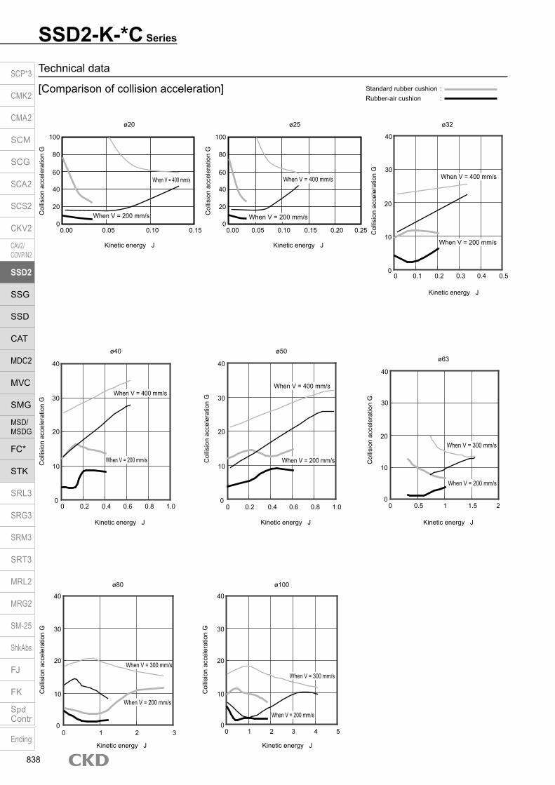
SSD2-K-*C Series
Technical data
[Comparison of collision acceleration] Standard rubber cushion :Rubber-air cushion :
ø63
ø100ø80
ø32
ø50ø40
ø25ø20
100
80
60
40
20
00.00 0.05 0.10 0.15
Kinetic energy J
Col
lisio
n ac
cele
ratio
n G
When V = 400 mm/s
When V = 200 mm/s
100
80
60
40
20
00.00 0.05 0.15 0.25
Kinetic energy J
Col
lisio
n ac
cele
ratio
n G
When V = 400 mm/s
When V = 200 mm/s
0.10 0.20 Col
lisio
n ac
cele
ratio
n G
40
20
30
0
10
0 0.1 0.2 0.3 0.4 0.5
Kinetic energy J
When V = 400 mm/s
When V = 200 mm/s
Col
lisio
n ac
cele
ratio
n G
40
20
30
0
10
0 0.5 1 1.5 2
Kinetic energy J
When V = 300 mm/s
When V = 200 mm/s
Col
lisio
n ac
cele
ratio
n G
40
20
30
0
10
0 0.2
Kinetic energy J
When V = 400 mm/s
When V = 200 mm/s
0.4 0.6 0.8 1.0
Col
lisio
n ac
cele
ratio
n G
40
20
30
0
10
0 0.2
Kinetic energy J
0.4 0.6 0.8 1.0
When V = 400 mm/s
When V = 200 mm/s
0 1
Kinetic energy J
2 3
Col
lisio
n ac
cele
ratio
n G
40
20
30
0
10
When V = 300 mm/s
When V = 200 mm/s
0 1
Kinetic energy J
2 3 4 5
When V = 300 mm/s
When V = 200 mm/s
Col
lisio
n ac
cele
ratio
n G
40
20
30
10
0
SCP*3
CMK2
CMA2
SCM
SCG
SCA2
SCS2
CKV2
CAV2/COVP/N2
SSD2
SSG
SSD
CAT
MDC2
MVC
SMG
MSD/MSDG
FC*
STK
SRL3
SRG3
SRM3
SRT3
MRL2
MRG2
SM‑25
ShkAbs
FJ
FK
SpdContr
Ending
838

[Allowable energy value]
SSD2-K-*C Series
Usable in the range below and to the left of the curve.Although it can also be used in the range marked with in the figure, we recommend use within the range marked with a solid line to maximize the noise reduction effect.
Col
lisio
n ac
cele
ratio
n G
Col
lisio
n ac
cele
ratio
n G
1000 200 300 400 500
Piston speed mm/s
0
10
20
30
40
50
60
Load
kg
ø50
ø40
ø32
1000 200 300 400 500
Piston speed mm/s
0
50
100
150
200
250
Load
kg
ø63
ø80
ø100
1000 200 300 400 500
Piston speed mm/s
0
3
6
9
12
15
Load
kg
ø25
ø20
SCP*3
CMK2
CMA2
SCM
SCG
SCA2
SCS2
CKV2
CAV2/COVP/N2
SSD2
SSG
SSD
CAT
MDC2
MVC
SMG
MSD/MSDG
FC*
STK
SRL3
SRG3
SRM3
SRT3
MRL2
MRG2
SM‑25
ShkAbs
FJ
FK
SpdContr
Ending
839
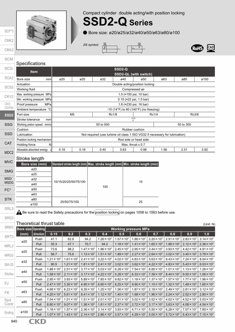
Compact cylinder double acting/with position locking
SSD2-Q Series Bore size: ø20/ø25/ø32/ø40/ø50/ø63/ø80/ø100
SpecificationsItem
SSD2-QSSD2-QL (with switch)
Bore size mm ø20 ø25 ø32 ø40 ø50 ø63 ø80 ø100Actuation Double acting/position lockingWorking fluid Compressed airMax. working pressure MPa 1.0 (≈150 psi, 10 bar)Min. working pressure MPa 0.15 (≈22 psi, 1.5 bar)Proof pressure MPa 1.6 (≈230 psi, 16 bar)Ambient temperature °C -10 (14°F) to 60 (140°F) (no freezing)Port size M5 Rc1/8 Rc1/4 Rc3/8Stroke tolerance mm +2.5
0
Working piston speed mm/s 50 to 500 50 to 300Cushion Rubber cushionLubrication Not required (use turbine oil class 1 ISO VG32 if necessary for lubrication)Position locking mechanism Rod side or head sideHolding force N Max. thrust x 0.7Allowable absorbed energy J 0.16 0.16 0.40 0.63 0.98 1.56 2.51 3.92
Stroke lengthBore size (mm) Standard stroke length (mm) Max. stroke length (mm) Min. stroke length (mm)
ø20
10/15/20/25/50/75/100100
10
ø25ø32ø40ø50ø63ø80
25/50/75/100 25ø100
Be sure to read the Safety precautions for the position locking on pages 1058 to 1063 before use.
JIS symbol
Bore size (mm)
Operating direction
Working pressure MPa0.15 0.2 0.3 0.4 0.5 0.6 0.7 0.8 0.9 1.0
ø20Push 47.1 62.8 94.2 1.26×10² 1.57×10² 1.88×10² 2.20×10² 2.51×10² 2.83×10² 3.14×10²
Pull 35.3 47.1 70.7 94.2 1.18×10² 1.41×10² 1.65×10² 1.88×10² 2.12×10² 2.36×10²
ø25Push 73.6 98.2 1.47×10² 1.96×10² 2.45×10² 2.95×10² 3.44×10² 3.93×10² 4.42×10² 4.91×10²
Pull 56.7 75.6 1.13×10² 1.51×10² 1.89×10² 2.27×10² 2.64×10² 3.02×10² 3.40×10² 3.78×10²
ø32Push 1.21×10² 1.61×10² 2.41×10² 3.22×10² 4.02×10² 4.83×10² 5.63×10² 6.43×10² 7.24×10² 8.04×10²
Pull 90.5 1.21×10² 1.81×10² 2.41×10² 3.02×10² 3.62×10² 4.22×10² 4.83×10² 5.43×10² 6.03×10²
ø40Push 1.88×10² 2.51×10² 3.77×10² 5.03×10² 6.28×10² 7.54×10² 8.80×10² 1.01×10³ 1.13×10³ 1.26×10³
Pull 1.58×10² 2.11×10² 3.17×10² 4.22×10² 5.28×10² 6.33×10² 7.39×10² 8.44×10² 9.50×10² 1.06×10³
ø50Push 2.95×10² 3.93×10² 5.89×10² 7.85×10² 9.82×10² 1.18×10³ 1.37×10³ 1.57×10³ 1.77×10³ 1.96×10³
Pull 2.47×10² 3.30×10² 4.95×10² 6.60×10² 8.25×10² 9.90×10² 1.15×10³ 1.32×10³ 1.48×10³ 1.65×10³
ø63Push 4.68×10² 6.23×10² 9.35×10² 1.25×10³ 1.56×10³ 1.87×10³ 2.18×10³ 2.49×10³ 2.81×10³ 3.12×10³
Pull 4.20×10² 5.61×10² 8.41×10² 1.12×10³ 1.40×10³ 1.68×10³ 1.96×10³ 2.24×10³ 2.52×10³ 2.80×10³
ø80Push 7.54×10² 1.01×10³ 1.51×10³ 2.01×10³ 2.51×10³ 3.02×10³ 3.52×10³ 4.02×10³ 4.52×10³ 5.03×10³
Pull 6.80×10² 9.07×10² 1.36×10³ 1.81×10³ 2.27×10³ 2.72×10³ 3.17×10³ 3.63×10³ 4.08×10³ 4.54×10³
ø100Push 1.18×10³ 1.57×10³ 2.36×10³ 3.14×10³ 3.93×10³ 4.71×10³ 5.50×10³ 6.28×10³ 7.07×10³ 7.85×10³
Pull 1.07×10³ 1.43×10³ 2.14×10³ 2.86×10³ 3.57×10³ 4.29×10³ 5.00×10³ 5.72×10³ 6.43×10³ 7.15×10³
Theoretical thrust table (Unit: N)
SCP*3
CMK2
CMA2
SCM
SCG
SCA2
SCS2
CKV2
CAV2/COVP/N2
SSD2
SSG
SSD
CAT
MDC2
MVC
SMG
MSD/MSDG
FC*
STK
SRL3
SRG3
SRM3
SRT3
MRL2
MRG2
SM‑25
ShkAbs
FJ
FK
SpdContr
Ending
840

SSD2-Q SeriesSpecifications
Switch specifications (F switch) 1-color/2-color display
ItemProximity 2-wire Proximity 3-wire Proximity 2-wire Proximity 3-wire
F2S F3S F2H/F2VF2YH/F2YV
F3H/F3V F3PH/F3PV (made to order) F3YH/F3YV
Applications Dedicated for programmable controller
For programmable controller, relay
Dedicated for programmable controller
For programmable controller, relay
Output method - NPN output - NPN output PNP output NPN output
Power supply voltage - 10 to 28 VDC - 10 to 28 VDC 4.5 to 28 VDC 10 to 28 VDC
Load voltage 10 to 30 VDC 30 VDC or less 10 to 30 VDC 24 VDC ±10% 30 VDC or lessLoad current 5 to 20 mA 50 mA or less 5 to 20 mA 50 mA or less
Indicator lamp LED(Lit when ON)
Yellow LED(Lit when ON)
Red/greenLED
(Lit when ON)
Yellow LED(Lit when ON)
Red/greenLED
(Lit when ON)Leakage current 1 mA or less 10 μA or less 1 mA or less 10 μA or lessWeight g 1 m:10 3 m:29
Switch specifications (T switch) 1-color/2-color display/for AC magnetic field proof
ItemProximity 2-wire Proximity 2-wire Proximity 3-wire Reed 2-wire Proximity 2-wire
T1H/T1VT2H/T2V/
T2JH/T2JVT2YH/T2YV
T2WH/ T2WV
T3H/T3VT3PH/T3PV
T3YH/T3YV
T3WH/ T3WV
T0H/T0V T5H/T5V T8H/T8VT2YD(*4)T2YDT
ApplicationsFor programmable
controller, relay, compact solenoid valve
Dedicated for programmable controller
For programmable controller, relay
For programmable controller, relay
For programmable controller, relay, IC circuit (no indicator
lamp), serial connection
For programmable controller, relay
For programmable
controllerOutput method - NPN output PNP output NPN output NPN output -Pwr. supp. V. - 10 to 28 VDC -Load voltage 85 to 265 VAC 10 to 30 VDC 24 VDC ±10% 30 VDC or less 12/24 VDC 100/110 VAC 5/12/24 VDC 100/110 VAC 12/24 VDC 110 VAC 220 VAC 24 VDC ±10%Load current 5 to 100 mA 5 to 20 mA (*3) 100 mA or less 50 mA or less 5 to 50 mA 7 to 20 mA 50 mA or less 20 mA or less 5 to 50 mA 7 to 20 mA 7 to 10 mA 5 to 20 mA
Indicator lamp
LED(Lit when
ON)
LED (Lit when ON)
Red/green LED (Lit
when ON)
Red/green LED (Lit
when ON)
LED (Lit when ON)
Yellow LED (Lit
when ON)
Red/green LED (Lit
when ON)
Red/green LED (Lit
when ON)
LED(Lit when ON)
Without indicator lamp
LED(Lit when ON)
Red/green LED
(Lit when ON)Leakage current
≤ 1 mA at 100 VAC, ≤ 2 mA at 200 VAC
1 mA or less 10 μA or less 0 mA1 mA or
less
Weight g1 m:333 m:875 m:142
1 m:183 m:495 m:80
1 m:333 m:875 m:142
1 m:183 m:495 m:80
1 m:183 m:495 m:80
1 m:333 m:875 m:142
1 m:183 m:495 m:80
1 m:18 3 m:49 5 m:801 m:333 m:875 m:142
1 m:613 m:1665 m:272
*1 : Refer to Ending Page 1 for detailed switch specifications and dimensions. *2 : Switches other than the above models, such as switches with connectors, are also available. Refer to Ending Page 1. *3 : The max. load current is 20 mA at 25°C. The current is lower than 20 mA if the operating ambient temperature around the switch is higher than 25˚C.
(5 to 10 mA at 60°C) *4 : Switch for AC magnetic field (T2YD/T2YDT) cannot be used in DC magnetic field. *5 : The F type switch uses a bend-resistant lead wire.
Cylinder weight table (the weight of the switches is when there are 2 cylinder switches.) With rod side position locking Stroke length (mm) 10 15 20 25 50 75 100Bore size (mm) No switch With switch No switch With switch No switch With switch No switch With switch No switch With switch No switch With switch No switch With switch
ø20 201 242 213 254 226 267 238 279 330 370 392 433 455 495ø25 274 315 290 331 306 347 322 363 439 480 519 560 599 640ø32 430 474 451 495 473 517 494 538 602 646 709 753 817 861ø40 632 681 658 708 685 734 711 761 844 893 976 1026 1109 1158ø50 1096 1147 1138 1189 1180 1231 1222 1273 1432 1483 1642 1693 1852 1903ø63 1609 1663 1664 1718 1719 1773 1774 1828 2049 2103 2324 2378 2599 2653ø80 - - - - - - 3822 3882 4255 4315 4904 4964 5336 5396
ø100 - - - - - - 5769 5835 6339 6405 7194 7260 7764 7830
With head side position locking Stroke length (mm) 10 15 20 25 50 75 100Bore size (mm) No switch With switch No switch With switch No switch With switch No switch With switch No switch With switch No switch With switch No switch With switch
ø20 217 258 230 270 242 283 255 295 330 370 392 433 455 495ø25 295 336 311 352 327 368 343 384 439 480 519 560 599 640ø32 462 506 484 528 505 549 527 571 634 678 742 786 849 893ø40 688 737 714 763 741 790 767 816 900 949 1032 1081 1165 1214ø50 1180 1231 1222 1273 1264 1315 1306 1357 1516 1567 1726 1777 1936 1987ø63 1675 1729 1730 1784 1785 1839 1840 1894 2115 2169 2390 2444 2665 2719ø80 - - - - - - 3952 4012 4385 4445 4904 4964 5336 5396
ø100 - - - - - - 5940 6006 6510 6576 7194 7260 7764 7830
(Unit: g)
(Unit: g)
SCP*3
CMK2
CMA2
SCM
SCG
SCA2
SCS2
CKV2
CAV2/COVP/N2
SSD2
SSG
SSD
CAT
MDC2
MVC
SMG
MSD/MSDG
FC*
STK
SRL3
SRG3
SRM3
SRT3
MRL2
MRG2
SM‑25
ShkAbs
FJ
FK
SpdContr
Ending
841

SSD2-Q Series
Bore sizeA
How to order Without switch (without magnet for switch)
With switch (built-in magnet for switch)
20 ILBR
Switch quantityF
*1*6
Switch model No.E
20 R ILB
10
Position locking mechanismD
Stroke lengthC
10 R
G Option*2
Port threadB
Accessory *5
I
Mounting bracket *3*4
H
Code DescriptionBore size (mm)
20 ø2025 ø2532 ø3240 ø4050 ø5063 ø6380 ø80
100 ø100
Port threadBlank Rc thread
NN NPT thread (ø32 and over) (made-to-order product)GN G thread (ø32 and over) (made-to-order product)
Stroke length (mm)
Refer to the stroke length table on the following page.
Position locking mechanismR With rod side position lockingH With head side position locking
* Lead wire lengthBlank 1 m (standard)
3 3 m (option)5 5 m (option) *8
Switch quantityR 1 on rod sideH 1 on head sideD 2
OptionBlank Rod end female thread
N Rod end male threadM0 Non-locking manual override (with release bolt)M1 Locking manual overrideP4 Specifications for rechargeable battery (made to order)P40
Mounting bracketBlank Without mounting bracket
LB Axial footCB Clevis bracket (pin and snap ring included)FA Rod side flangeFB Head side flange
Accessory (available when rod end male thread “N” is selected)I Rod eyeY Rod clevis (pin and snap ring included)
A
B
C
G
H
I
F
Switch model No.Lead wire Lead wire
Conta
ct Voltage Display Lead wire
Bore sizeStraight L-shaped AC DC 20 25 32 40 50 63 80 100
- F2S*
Pro
xim
ity
1-color display
2-wire - F3S* 3-wire
F2H* F2V* 2-wire F3H* F3V* 3-wire
F3PH* F3PV* 1 color display (PNP output) (custom) 3-wire F2YH* F2YV*
2-color display 2-wire F3YH* F3YV* 3-wire T0H* T0V*
Ree
d 1-color display2-wire
T5H* T5V* Without indicator lamp T8H* T8V* 1-color display T1H* T1V*
Pro
xim
ity
1-color display 2-wire
T2H* T2V* T3H* T3V*
3-wire
T3PH* T3PV* 1-color display (PNP output) T2WH* T2WV*
2-color display2-wire
T2YH* T2YV* T3WH* T3WV*
3-wire
T3YH* T3YV* T2YD* - 2-color display
for AC magnetic field 2-wire
T2YDT* - T2JH* T2JV* 1-color display off-delay 2-wire
D
E
Precautions for model No. selection*1 : The F switch can only be mounted on the piping port
surface of bore sizes ø20 and ø25.*2 : Only non-locking manual override unless “M0” or “M1”
of G option is selected. A release bolt is not included.*3 : The mounting bracket is included at shipment.*4 : The projection dimension of piston rod WF when LB
or FA is selected is different from that of the standard. Refer to the dimensions on pages 847, 848, 850 and 851. The number of the specified protruding dimension will be added at the end of the model No. printed on the metal plate on the body.
*5 : ”I” and “Y” cannot be selected together.*6 : Switches are shipped with the product. Contact CKD if
assembling before shipment is necessary.*7 : Refer to pages 750 and 751 for combinations of
variations/options.*8 : F type switch cannot be selected.
[Example of model No.]SSD2-QL-20-10-R-T0H-R-N-LB-IModel: Compact cylinder, position lockingA Bore size : ø20 mmB Port thread : Rc threadC Stroke length : 10mmD Position locking mechanism : With rod side position lockingE Switch model No. : Reed switch T0H, lead wire 1 mF Switch quantity : 1 on rod sideG Option : Rod end male threadH Mounting bracket : Axial footI Accessory : Rod eye
How to order switch
Switch model No. (Item E above)
SSD2-Q
SSD2-QL T0H
NMO
NMO
SW T0H
SCP*3
CMK2
CMA2
SCM
SCG
SCA2
SCS2
CKV2
CAV2/COVP/N2
SSD2
SSG
SSD
CAT
MDC2
MVC
SMG
MSD/MSDG
FC*
STK
SRL3
SRG3
SRM3
SRT3
MRL2
MRG2
SM‑25
ShkAbs
FJ
FK
SpdContr
Ending
842

SSD2-Q SeriesHow to order
Stroke length (mm)Applicable bore size
ø20 ø25 ø32 ø40 ø50 ø63 ø80 ø100
Sta
ndar
d st
roke
leng
th 10 15 20 25 50 75
100 Min. stroke length (mm) 10 25Max. stroke length (mm) 100
[Stroke length table]
Bore size (mm)ø20 ø25 ø32 ø40 ø50 ø63 ø80
Mounting bracketFoot (LB) SSD2-LB-20 SSD2-LB-25 SSD2-LB-32 SSD2-LB-40 SSD2-LB-50 SSD2-LB-63 SSD2-LB-80Flange (FA/FB) SSD2-FA-20 SSD2-FA-25 SSD2-FA-32 SSD2-FA-40 SSD2-FA-50 SSD2-FA-63 SSD2-FA-80Clevis bracket (CB) SSD2-CB-20 SSD2-CB-25 SSD2-CB-32 SSD2-CB-40 SSD2-CB-50 SSD2-CB-63 SSD2-CB-80
Bore size (mm)ø100
Mounting bracketFoot (LB) SSD2-LB-100Flange (FA/FB) SSD2-FA-100Clevis bracket (CB) SSD2-CB-100*1: The foot mounting bracket is provided as 2 pcs./set.
How to order mounting bracket
[Explanation of manual override] Non-locking manual override (option code: M0)
By screwing the hexagon socket head cap screw (M3 x 30) into the stopper piston and pulling the bolt with force of 20 N or more, the stopper piston moves and the lock is released. (Perform when horizontally installed with no load or when the opposite side port is pressurized) When you release the bolt, the stopper piston is returned to the original position and engaged in the groove, and the piston is locked.
By rotating the round nut leftward (counterclockwise), the stopper piston moves and the lock is released. Locking the round nut by rotating it to the right (clockwise) causes the stopper piston to return. When it fits into the lock groove, the piston is locked. Screw in the round nut fully, since the cylinder may be damaged if the stopper piston is not securely locked in the groove.
Locking manual override (option code: M1)
Hexagon socket head cap screw: M3 x 30
Spring
Stopper piston
Travel
distan
ce 3m
m23
.5
Round nut
Travel
distan
ce 2.5
to 3 m
mDim
ensio
nsRe
feren
ce
SCP*3
CMK2
CMA2
SCM
SCG
SCA2
SCS2
CKV2
CAV2/COVP/N2
SSD2
SSG
SSD
CAT
MDC2
MVC
SMG
MSD/MSDG
FC*
STK
SRL3
SRG3
SRM3
SRT3
MRL2
MRG2
SM‑25
ShkAbs
FJ
FK
SpdContr
Ending
843

SSD2-Q Series
Internal structure and parts list (ø20 to ø50) SSD2-QL-20 to 50-R
(double acting/single rod/with switch/rod side position locking)
SSD2-Q-20 to 50-R (double acting/single rod/rod side position locking)
SSD2-Q-20 to 50-H (double acting/single rod/head side position locking)
ø20, ø25: 50 stroke length and over ø20, ø25: 50 stroke length and over
Repair parts listBore size (mm) Kit No. Repair parts No.
ø20 SSD2-Q-20K3 4 7 10 15
17 18 21 24 25
ø25 SSD2-Q-25Kø32 SSD2-Q-32Kø40 SSD2-Q-40Kø50 SSD2-Q-50K
*1: 24 is included only with ø20 and ø25.
No. Part name Material Remarks No. Part name Material Remarks
1 Piston rod ø20 to ø25: Stainless steelø32 to ø50: Steel
Industrial chrome plating 16 Stopper piston Steel Nitriding
2 C snap ring Steel Zinc phosphate 17 Stopper packing Nitrile rubber3 Rod packing Nitrile rubber 18 O-ring Nitrile rubber4 Rod metal gasket Nitrile rubber
19 Stopper housingø20 to ø30, ø50: Aluminum alloy Alumite
5 Rod metal Special aluminum Alumite ø40: Alloy steel Chromate6 Rod cover Aluminum alloy Alumite 20 Stopper cover Aluminum alloy Chromate7 Cushion rubber (R) Urethane rubber 21 Cushion rubber Urethane rubber8 Spacer Aluminum alloy ø20 to ø32: Chromate 22 Coil spring Piano wire Electrodeposition9 Magnet Plastic 23 Hexagon socket head cap screw Steel
10 Piston packing Nitrile rubber 24 Wear ring Polyacetal resin (only for ø20 and ø25 with 50 mm stroke length and over)
11 Piston Aluminum alloy Chromate 25 Cushion rubber (H) Urethane rubber12 Spring pin Steel Black finish 26 Sleeve Steel Nitriding13 Body Aluminum alloy Hard alumite 27 Cover Aluminum alloy Chromate14 Head cover Aluminum alloy Chromate 28 Round nut Aluminum alloy15 O-ring Nitrile rubber 29 Hexagon socket head cap screw Steel
Parts list
SSD2-QL-20 to 50-H (double acting/single rod/with switch/head side position locking)
Locking manual override
1 2 43 76 9 1310
15
118
24
17 16 21 22 20 23 19 25 18 1 2 43 75 10 159 118 17 20 1622 21 23 19
1225 26 1413 18
29 28
27
1 2 43 76 1310
15
118
17 16 21 22 20 23 19 25 18
27 1225 26 1413 18
1 2 43 75 10 15118 17 22 1620 21 23 19
24
SCP*3
CMK2
CMA2
SCM
SCG
SCA2
SCS2
CKV2
CAV2/COVP/N2
SSD2
SSG
SSD
CAT
MDC2
MVC
SMG
MSD/MSDG
FC*
STK
SRL3
SRG3
SRM3
SRT3
MRL2
MRG2
SM‑25
ShkAbs
FJ
FK
SpdContr
Ending
844

Locking manual override
Internal structure and parts list (ø63 to ø100) SSD2-QL-63 to 100-R
(double acting/single rod/with switch/rod side position locking)
SSD2-Q SeriesInternal structure and parts list
SSD2-Q-63 to 100-R (double acting/single rod/rod side position locking)
SSD2-Q-63 to 100-H (double acting/single rod/head side position locking)
ø80, ø100: 75 stroke length and over ø80, ø100: 75 stroke length and over
Repair parts listBore size (mm) Kit No. Repair parts No.
ø63 SSD2-Q-63K 3 4 8 11 16
18 19 22 25 26ø80 SSD2-Q-80K
ø100 SSD2-Q-100K*1: 25 is included only with ø80 and ø100.
No. Part name Material Remarks No. Part name Material Remarks1 Piston rod Steel Industrial chrome plating 17 Stopper piston Steel Nitriding2 C snap ring Steel Zinc phosphate 18 Stopper packing Nitrile rubber3 Rod packing Nitrile rubber 19 O-ring Nitrile rubber4 Rod metal gasket Nitrile rubber
20 Stopper housingø80: Aluminum alloy Alumite
5 Rod metal Special aluminum Alumite ø63, ø100: Alloy steel Chromate6 Rod cover Aluminum alloy Alumite 21 Stopper cover Aluminum alloy Chromate7 Bush Oiles drymet 22 Cushion rubber Urethane rubber8 Cushion rubber (R) Urethane rubber 23 Coil spring Piano wire Electrodeposition9 Spacer Aluminum alloy 24 Hexagon socket head cap screw Steel
10 Magnet Plastic 25 Wear ring Polyacetal resin (only for ø80 and ø100 with 75 mm stroke length and over)
11 Piston packing Nitrile rubber 26 Cushion rubber (H) Urethane rubber12 Piston Aluminum alloy Chromate 27 Sleeve Steel Nitriding13 Spring pin Steel Black finish 28 Cover Aluminum alloy Chromate14 Body Aluminum alloy Hard alumite 29 Round nut Aluminum alloy15 Head cover Aluminum alloy Chromate 30 Hexagon socket head cap screw Steel16 O-ring Nitrile rubber
Parts list
SSD2-QL-63 to 100-H (double acting/single rod/with switch/head side position locking)
25
29 30
18 16 22 2117 23 24 20 19 26
1 3 42 76 129 118 1410 28
18 16 22 2117 23 24 20 19 26
1 3 42 76 129 118 14 28
1 3 52 84 2118 2316 1722 24 20
7 12119 2610 27 1914 15
1 3 52 84 2118 2316 1722 24 20
7 1112 269 27 1514 19
25
SCP*3
CMK2
CMA2
SCM
SCG
SCA2
SCS2
CKV2
CAV2/COVP/N2
SSD2
SSG
SSD
CAT
MDC2
MVC
SMG
MSD/MSDG
FC*
STK
SRL3
SRG3
SRM3
SRT3
MRL2
MRG2
SM‑25
ShkAbs
FJ
FK
SpdContr
Ending
845

SSD2-Q Series
Dimensions (ø20, ø25) SSD2-Q(L)-20 to 25-R
* The dimensions are common for types with and without switches. Rod end male thread
Precautions regarding the switch mounting groove*1: Only F switch is available for the ø20 or ø25 piping port surface.
Code Common dimensionsBore size (mm) EE F I J K KA KK M MM N WF *1 Q QC
ø20 M5 36 5.5 9 spot face depth 5.5 47 M6 depth 11 M5 depth 7 8 10 25.5 4.5(14.5) 28.5 40
ø25 M5 40 5.5 9 spot face depth 5.5 51 M6 depth 11 M6 depth 12 10 12 28 5(15) 29.5 41
Code With rod side position locking mechanism With head side position locking mechanismBore size (mm) A *1 B *1 C D R A *1 B *1 C D R
ø20 59(80.5) 54.5(66) 9.5 8 18.6 65.5(80.5) 61(66) 9.5 8 17.3
ø25 62.5(84) 57.5(69) 12 8.5 19.3 69(84) 64(69) 12 8.5 18.4
Codea’ c’ H kk’ M MM T wf *1
Bore size (mm)ø20 14 12 13 M8 8 10 5 4.5(14.5)
ø25 17.5 15 17 M10×1.25 10 12 6 5(15)
Rod end male thread
*1 : Dimensions in ( ) are for stroke lengths of more than 25 mm.*2 : Refer to pages 852 and 853 for switch mounting position.*3 : For dimensions of individual accessories, refer to pages 1046 to 1049.
SSD2-Q(L)-20 to 25-H* The dimensions are common for types with and without switches.
a’c’
T
wf
øMM
kk’Width across flats M
Width across flats H
8-JMounting hole
21
øK
F
Q
M
F
N
øMM
WF
KK
C D
2-EE
8-KA
øI
A + stroke lengthB + stroke length
ø10.5R
23
8-JMounting hole
21
øK
F
Q
M
F
N
øMM
WF
KK
C D
2-EE
8-KA øIA + stroke length
B + stroke length
ø10.5R
23
QC
(MA
X)
SCP*3
CMK2
CMA2
SCM
SCG
SCA2
SCS2
CKV2
CAV2/COVP/N2
SSD2
SSG
SSD
CAT
MDC2
MVC
SMG
MSD/MSDG
FC*
STK
SRL3
SRG3
SRM3
SRT3
MRL2
MRG2
SM‑25
ShkAbs
FJ
FK
SpdContr
Ending
846

Dimensions with mounting bracket Axial foot (LB) SSD2-Q(L)-20, 25 -LB
SSD2-Q SeriesDimensions
Code Common dimensions Female thread SSD2-Q-R (female thread)Bore size
(mm) AB AG AH AK AT AU G N TR TS M WF LF Without/with switchA B LX
ø20 7 42 24 15 3.2 9.2 M6×16 25.5 48 62 7.2 14.5 20.5 76.2(87.7) 54.5(66) 42.5(54)ø25 7 46 26 16.5 3.2 10.7 M6×16 28 52 66 7.2 15 22.5 79.7(91.2) 57.5(69) 42.5(54)
Code SSD2-Q-R (male thread) SSD2-Q-H (female thread)Bore size
(mm) a’ wf LF Without/with switch WF LF Without/with switchA B LX A B LX
ø20 14 14.5 20.5 90.2(101.7) 54.5(66) 42.5(54) 14.5 20.5 82.7(87.7) 61(66) 49(54)ø25 17.5 15 22.5 97.2(108.7) 57.5(69) 42.5(54) 15 22.5 86.2(91.2) 64(69) 49(54)
Code SSD2-Q-H (male thread)Bore size
(mm) a’ wf LF Without/with switchA B LX
ø20 14 14.5 20.5 96.7(101.7) 61(66) 49(54)ø25 17.5 15 22.5 103.7(108.7) 64(69) 49(54)
Clevis bracket (CB)SSD2-Q(L)-20, 25 -CB
Code Common dimensions SSD2-Q-R (female thread)
Bore size (mm) CA CB CC CD D E G H N UB WF A B CJ
ø20 20 8.2 + 0.2 0 12 8 5 36 M6×16 C4 25.5 16 -0.1
-0.3 4.5(14.5) 86(107.5) 54.5(66) 77(98.5)
ø25 24 10.2 + 0.2 0 14 10 5 40 M6×16 C5 28 20 -0.1
-0.3 5(15) 92.5(114) 57.5(69) 82.5(104)
Code SSD2-Q-R (male thread) SSD2-Q-H (female thread)
Bore size (mm) a’ wf A B CJ WF A B CJ
ø20 14 4.5(14.5) 100(121.5) 54.5(66) 77(98.5) 4.5(14.5) 92.5(107.5) 61(66) 83.5(98.5)
ø25 17.5 5(15) 110(131.5) 57.5(69) 82.5(104) 5(15) 99(114) 64(69) 89(104)
Code SSD2-Q-H (male thread)
Bore size (mm) a’ wf A B CJ
ø20 14 4.5(14.5) 106.5(121.5) 61(66) 83.5(98.5)
ø25 17.5 5(15) 116.5(131.5) 64(69) 89(104)
* Dimensions in ( ) are for ø20 and ø25 with more than 25 mm stroke length and ø80 and ø100 with more than 50 mm stroke length.
*1: Dimensions in ( ) are for more than 25 mm stroke length.
N
AG N
TRTS
AT
AH
4-øAB
WFA + stroke length
B + stroke length M
AUAK
Low head hexagon socket bolt 8-G
LX + stroke lengthLF
A + stroke lengthB + stroke lengtha’ wf
LF
Rod end male thread
N
WF A + stroke lengthB + stroke lengtha’ wf
Rod end male thread
A + stroke lengthB + stroke length
H
CJ + stroke lengthMounting bolt 4-G
N
E
E
CBCC
UBD
øCA
CDH10 CJ + stroke length
SCP*3
CMK2
CMA2
SCM
SCG
SCA2
SCS2
CKV2
CAV2/COVP/N2
SSD2
SSG
SSD
CAT
MDC2
MVC
SMG
MSD/MSDG
FC*
STK
SRL3
SRG3
SRM3
SRT3
MRL2
MRG2
SM‑25
ShkAbs
FJ
FK
SpdContr
Ending
847

Head side flange (FB) SSD2-Q(L)-20, 25 -FB
Code Common dimensions SSD2-Q-R (female thread) SSD2-Q-R (male thread)
Bore size (mm) FD FH FL FM FT N G WF
Without/with switcha’ wf
Without/with switchA B A B
ø20 6.6 39 48 60 8 25.5 M6×16 14.5 69(80.5) 54.5(66) 14 14.5 83(94.5) 54.5(66)
ø25 6.6 42 52 64 8 28 M6×16 15 72.5(84) 57.5(69) 17.5 15 90(101.5) 57.5(69)
Code Common dimensions SSD2-Q-R (female thread) SSD2-Q-R (male thread)
Bore size (mm) FD FH FL FM FT N G WF A B a’ wf A B
ø20 6.6 39 48 60 8 25.5 M6×16 4.5(14.5) 67(88.5) 54.5(66) 46 19.5(14.5) 71(92.5) 54.5(66)
ø25 6.6 42 52 64 8 28 M6×16 5(15) 70.5(92) 57.5(69) 53 22.5(15) 88(109.5) 57.5(69)
Code SSD2-Q-H (female thread) SSD2-Q-H (male thread)
Bore size (mm) WF
Without/with switcha’ wf
Without/with switchA B A B
ø20 14.5 75.5(80.5) 61(66) 14 14.5 89.5(94.5) 61(66)
ø25 15 79(84) 64(69) 17.5 15 96.5(101.5) 64(69)
Code SSD2-Q-H (female thread) SSD2-Q-H (male thread)
Bore size (mm) WF A B a’ wf A B
ø20 4.5(14.5) 73.5(88.5) 61(66) 46 19.5(14.5) 77.5(92.5) 61(66)
ø25 5(15) 77(92) 64(69) 53 22.5(15) 94.5(109.5) 64(69)
SSD2-Q Series
Dimensions with mounting bracket Rod side flange (FA) SSD2-Q(L)-20, 25 -FA
* Dimensions in ( ) are for ø20 and ø25 with more than 25 mm stroke length and ø80 and ø100 with more than 50 mm stroke length.
*1: Dimensions in ( ) are for more than 25 mm stroke length.
N
FM
FH
WF
Mounting bolt 4-GHexagon socket button head bolt
A + stroke lengthB + stroke lengtha’ wf FT
FL
Rod end male thread
A + stroke lengthB + stroke length FT N
2-FD
A + stroke lengthB + stroke length
FM
NFH
N
2-FD
Mounting bolt 4-GHexagon socket button head bolt
Rod end male thread
FT
A + stroke lengthB + stroke length
FTa’ wfWFFL
SCP*3
CMK2
CMA2
SCM
SCG
SCA2
SCS2
CKV2
CAV2/COVP/N2
SSD2
SSG
SSD
CAT
MDC2
MVC
SMG
MSD/MSDG
FC*
STK
SRL3
SRG3
SRM3
SRT3
MRL2
MRG2
SM‑25
ShkAbs
FJ
FK
SpdContr
Ending
848

Dimensions (ø32 to ø100) SSD2-Q(L)-32 to 100-R
* The dimensions are common for types with and without switches. Rod end male thread
SSD2-Q(L)-32 to 100-H* The dimensions are common for types with and without switches.
Code a’ c’ H kk’ M MM T wf *1
Bore size (mm)ø32 23.5 20.5 22 M14×1.5 14 16 8 5ø40 23.5 20.5 22 M14×1.5 14 16 8 5ø50 28.5 26 27 M18×1.5 17 20 11 5ø63 28.5 26 27 M18×1.5 17 20 11 5ø80 35.5 32.5 32 M22×1.5 22 25 13 8(18)
ø100 35.5 32.5 41 M26×1.5 27 30 16 8(18)
Rod end male thread
*1 : Dimensions in ( ) are for stroke lengths of more than 50 mm.*2 : Refer to pages 852 and 853 for switch mounting position.*3 : For dimensions of individual accessories, refer to pages 1046 to 1049.
Code Common dimensionsBore size (mm) EE F G I J K KA KK M MM N
ø32 Rc1/8 45 49.5 5.5 9 spot face depth 5.5 60 M6 depth 11 M8 depth 13 14 16 34ø40 Rc1/8 52 57 5.5 9 spot face depth 5.5 69 M6 depth 11 M8 depth 13 14 16 40ø50 Rc1/4 64 71 6.9 11 spot face depth 6.5 86 M8 depth 13 M10 depth 15 17 20 50ø63 Rc1/4 77 84 8.7 14 spot face depth 9 103 M10 depth 25 M10 depth 15 17 20 60ø80 Rc3/8 98 104 10.5 17.5 spot face depth 11 132 M12 depth 28 M16 depth 21 22 25 77
ø100 Rc3/8 117 123.5 10.5 17.5 spot face depth 11 156 M12 depth 28 M20 depth 27 27 30 94Code Common dimensionsBore size (mm) O P S QB QC QD QE WF *1
ø32 4.5 22 30.5 33.5 46.3 10.5 13 7ø40 5 22 30.5 37 49.8 10.5 13 7ø50 7 40.5 23 44 56.3 10.5 13 8ø63 7 40.5 23 50.5 62.8 10.5 13 8ø80 6 47 47 62 77.5 14.5 24 10(20)
ø100 6.5 47 47 71.5 87 14.5 24 12(22)Code With rod side position locking mechanism With head side position locking mechanismBore size (mm) A *1 B *1 C D R A *1 B *1 C D R
ø32 65 58 11 9 19.2 72.5 65.5 11 9 20.9ø40 71.5 64.5 14 11 21.7 82 75 14 14 23.9ø50 73.5 65.5 15 12.5 24.7 83.5 75.5 15 12.5 29.8ø63 79 71 19 16 26.2 85 77 15 16 25.5ø80 113.5(136) 103.5(116) 18 17 40 121(136) 111(116) 18 17 37.5
ø100 125(147.5) 113(125.5) 23 21 44.5 132.5(147.5) 120.5(125.5) 23 21 40
SSD2-Q SeriesDimensions
a’c’
T
wf
øMM
kk’Width across flats M
Width across flats H
8-JMounting holeP
øKF
QB
M
F
N
øMM
WF
KKC
D
2-EE
8-KA
øI
A + stroke length
B + stroke length
R
O
G
S
øQD
P
øKF
QB
M
FN
O
G
QC
(MA
X)
øQE
øMM
WF
KK
CD
2-EE
8-KA øIA + stroke lengthB + stroke length
RS
øQD
8-JMounting hole
SCP*3
CMK2
CMA2
SCM
SCG
SCA2
SCS2
CKV2
CAV2/COVP/N2
SSD2
SSG
SSD
CAT
MDC2
MVC
SMG
MSD/MSDG
FC*
STK
SRL3
SRG3
SRM3
SRT3
MRL2
MRG2
SM‑25
ShkAbs
FJ
FK
SpdContr
Ending
849

Dimensions with mounting bracket Axial foot (LB) SSD2-Q(L)-32 to 100 -LB
Code Common dimensions Female thread SSD2-Q-R (female thread)Bore size
(mm) AB AD AE AG AH AK AT AU G N TR TS M WF LF Without/with switchA B LX
ø32 7 18.5 13 57 30 17 3.2 11.2 M6×16 34 57 71 7.2 17 25 82.2 58 42ø40 7 18 13 64 33 18.2 3.2 11.2 M6×16 40 64 78 7.2 17 25 88.7 64.5 48.5ø50 9 22 14 78 39 22.7 3.2 14.7 M8×20 50 79 95 8.2 18 29.5 91.7 65.5 42.5ø63 11 26 16 91.5 46 25.2 3.2 16.2 M10×25 60 95 113 9.2 18 31 98.2 71 45ø80 13 31.5 20.5 114 59 30.5 4.5 19.5 M12×40 77 118 140 11.5 20 35 135(147.5) 103.5(116) 73.5(86)ø100 13 35 24 136 71 35.5 6 23 M12×40 94 137 162 13 22 39 148(160.5) 113(125.5) 79(91.5)
Code Common dimensions SSD2-Q-R (female thread)Bore size
(mm) AC CB CC CD D E G MR N UB WF A B CJ
ø32 4.5 18.2 14 10 5 45 M6×16 10 34 36 7 95 58 85ø40 5 18.2 14 10 6 52 M6×16 10 40 36 7 103.5 64.5 93.5ø50 6 22.2 20 14 7 64 M8×20 14 50 44 8 115.5 65.5 101.5ø63 7 22.2 20 14 8 77 M10×25 14 60 44 8 123 71 109ø80 9 28.2 27 18 10 98 M12×40 18 77 56 10(20) 169.5(192) 103.5(116) 151.5(174)ø100 12 32.2 31 22 13 117 M12×40 22 94 64 12(22) 192(214.5) 113(125.5) 170(192.5)
Code SSD2-Q-R (male thread) SSD2-Q-H (female thread) SSD2-Q-H (male thread)Bore size
(mm) a’ wf LF Without/with switch WF LF Without/with switch a’ wf LF Without/with switchA B LX A B LX A B LX
ø32 23.5 15 23 103.7 58 42 17 25 89.7 65.5 49.5 23.5 15 23 111.2 65.5 49.5ø40 23.5 15 23 110.2 64.5 48.5 17 25 99.2 75 59 23.5 15 23 120.7 75 59ø50 28.5 15 26.5 117.2 65.5 42.5 18 29.5 101.7 75.5 52.5 28.5 15 26.5 127.2 75.5 52.5ø63 28.5 15 28 123.7 71 45 18 31 104.2 77 51 28.5 15 28 129.7 77 51ø80 35.5 18 33 168.5(181) 103.5(116) 73.5(86) 20 35 142.5(147.5) 111(116) 81(86) 35.5 18 33 176(181) 111(116) 81(86)ø100 35.5 18 35 179.5(192) 113(125.5) 79(91.5) 22 39 155.5(160.5) 120.5(125.5) 86.5(91.5) 35.5 18 35 187(192) 120.5(125.5) 86.5(91.5)
Code SSD2-Q-R (male thread) SSD2-Q-H (female thread) SSD2-Q-H (male thread)Bore size
(mm) a’ wf A B CJ WF A B CJ a’ wf A B CJ
ø32 23.5 5 116.5 58 83 7 102.5 65.5 92.5 23.5 5 124 65.5 90.5ø40 23.5 5 125 64.5 91.5 7 114 75 104 23.5 5 135.5 74.5 102ø50 28.5 5 141 65.5 98.5 8 125.5 75.5 111.5 28.5 5 151 71.5 108.5ø63 28.5 5 148.5 71 106 8 129 77 115 28.5 5 154.5 77 112ø80 35.5 8(18) 203(225.5) 103.5(116) 149.5(172) 10(20) 177(192) 111(116) 159(174) 35.5 8(18) 210.5(225.5) 111(116) 157(172)ø100 35.5 8(18) 223.5(246) 113(125.5) 166(188.5) 12(22) 199.5(214.5) 120.5(125.5) 177.5(192.5) 35.5 8(18) 231(246) 120.5(125.5) 173.5(188.5)
SSD2-Q Series
Clevis bracket (CB) SSD2-Q(L)-32 to 100 -CB
* Dimensions in ( ) are for ø20 and ø25 with more than 25 mm stroke length and ø80 and ø100 with more than 50 mm stroke length.
*1: Dimensions in ( ) of ø80 and ø100 are for more than 50 mm stroke length.
NTRTS
4-øAB
AD
AE A
T AH
LF
A + stroke lengthRod end male thread B + stroke lengtha’ wf
LX + stroke length
A + stroke length
B + stroke length
Low head hexagon socket bolt 4-G
LF
WF
AUAK
M
AG
N
A + stroke length
Rod end male thread
B + stroke lengtha’ wf
A + stroke lengthB + stroke lengthWF
CJ + stroke lengthCJ + stroke length
CC
UBD
NE
E
CDH10
Mounting bolt 4-GAC
RMR
CB + 0.2 0
SCP*3
CMK2
CMA2
SCM
SCG
SCA2
SCS2
CKV2
CAV2/COVP/N2
SSD2
SSG
SSD
CAT
MDC2
MVC
SMG
MSD/MSDG
FC*
STK
SRL3
SRG3
SRM3
SRT3
MRL2
MRG2
SM‑25
ShkAbs
FJ
FK
SpdContr
Ending
850

Dimensions with mounting bracket Rod side flange (FA) SSD2-Q(L)-32 to 100 -FA
Head side flange (FB) SSD2-Q(L)-32 to 100 -FB
Code Common dimensions SSD2-Q-R (female thread) SSD2-Q-R (male thread)Bore size
(mm) FC FD FH FL FM FT N G WF Without/with switch a’ wf Without/with switchA B A B
ø32 34 5.5 48 56 65 8 34 M6×16 17 75 58 23.5 15 96.5 58ø40 40 5.5 54 62 72 8 40 M6×16 17 81.5 64.5 23.5 15 103 64.5ø50 50 6.6 67 76 89 9 50 M8×20 18 83.5 65.5 28.5 15 109 65.5ø63 60 9 80 92 108 9 60 M10×25 18 89 71 28.5 15 114.5 71ø80 77 11 99 116 134 11 77 M12×40 20 123.5(136) 103.5(116) 35.5 18 157(169.5) 103.5(116)
ø100 94 11 117 136 154 11 94 M12×40 22 135(147.5) 113(125.5) 35.5 18 166.5(179) 113(125.5)Code SSD2-Q-H (female thread) SSD2-Q-H (male thread)Bore size
(mm) WF Without/with switch a’ wf Without/with switchA B A B
ø32 17 82.5 65.5 23.5 15 104 65.5ø40 17 92 75 23.5 15 113.5 75ø50 18 93.5 75.5 28.5 15 119 75.5ø63 18 95 77 28.5 15 120.5 77ø80 20 131(136) 111(116) 35.5 18 164.5(169.5) 111(116)
ø100 22 142.5(147.5) 120.5(125.5) 35.5 18 174(179) 120.5(125.5)
Code Common dimensions SSD2-Q-R (female thread) SSD2-Q-R (male thread)Bore size
(mm) FC FD FH FL FM FT N G WF A B a’ wf A B
ø32 34 5.5 48 56 65 8 34 M6×16 7 73 58 59.5 23 94.5 58ø40 40 5.5 54 62 72 8 40 M6×16 7 79.5 64.5 66 29.5 101 64.5ø50 50 6.6 67 76 89 9 50 M8×20 8 82.5 65.5 73 30.5 108 65.5ø63 60 9 80 92 108 9 60 M10×25 8 88 71 78.5 36 113.5 71ø80 77 11 99 116 134 11 77 M12×40 10(20) 124.5(147) 103.5(116) 98 43.5(18) 158(180.5) 103.5(116)
ø100 94 11 117 136 154 11 94 M12×40 12(22) 136(158.5) 113(125.5) 107.5 53(18) 167.5(190) 113(125.5)Code SSD2-Q-H (female thread) SSD2-Q-H (male thread)Bore size
(mm) WF A B a’ wf A B
ø32 7 80.5 65.5 59.5 23 102 65.5ø40 7 90 75 66 29.5 111.5 74.5ø50 8 92.5 75.5 73 30.5 118 71.5ø63 8 94 77 78.5 36 119.5 77ø80 10(20) 132(147) 111(116) 98 43.5(18) 165.5(180.5) 111(116)ø100 12(22) 143.5(158.5) 120.5(125.5) 107.5 53(18) 175(190) 120.5(125.5)
SSD2-Q SeriesDimensions
* Dimensions in ( ) are for ø20 and ø25 with more than 25 mm stroke length and ø80 and ø100 with more than 50 mm stroke length.
*1: Dimensions in ( ) of ø80 and ø100 are for more than 50 mm stroke length.
Rod end male thread
A + stroke lengthB + stroke length
A + stroke lengthB + stroke lengtha’ wf
FTFT
FH FC
FM
NFL
4-FD
Mounting bolt 4-Gø32 to ø63: Hexagon socket button head boltø80/ø100: Special bolt
WF
FH FC
A + stroke length
Rod end male thread
B + stroke lengtha’ wfA + stroke lengthB + stroke lengthWF FT4-FD
FLN
Mounting bolt 4-G
FM
FT
ø32 to ø63: Hexagon socket button head boltø80/ø100: Special bolt
SCP*3
CMK2
CMA2
SCM
SCG
SCA2
SCS2
CKV2
CAV2/COVP/N2
SSD2
SSG
SSD
CAT
MDC2
MVC
SMG
MSD/MSDG
FC*
STK
SRL3
SRG3
SRM3
SRT3
MRL2
MRG2
SM‑25
ShkAbs
FJ
FK
SpdContr
Ending
851

Dimensions (with the 1-color display, 2-color display, off-delay, strong magnetic field proof, T1* or T8* switch) SSD2-QL-20 to 25-R (with switch/rod side position locking)
SSD2-QL-32 to 100-R (with switch/rod side position locking)
Code T2YH/T2YV, T3YH/T3YV, T2JH/T2JV T2YD, T2YDT, T1H/T1V T8H/T8V *1
Bore size (mm) FA FB HD RD FA FB HD RD FA FB HD RDø20 24.3 16 3 30 35 29.3 16 3 30 35 24.3 16 0 25.5 30.5
ø25 26.3 17 5.5 32 37 31.3 17 5.5 32 37 26.3 17 0.5 27 32
ø32 28.8 24 4 32.5 33.8 24 4 32.5 28.8 24 0 28
ø40 32.3 31 7 36.5 37.3 31 7 36.5 32.3 31 2 31.5
ø50 38.3 32 5.5 39.5 43.3 32 5.5 39.5 38.3 32 0.5 34.5
ø63 44.8 32 9 40.5 49.8 32 9 40.5 44.8 32 4 35.5
ø80 55.3 32 17.5 22.5 64.5 72 60.3 32 17.5 22.5 64.5 72 55.3 32 12.5 17.5 60 67.5
ø100 64.8 32 23 28 68.5 76 69.8 32 23 28 68.5 76 64.8 32 18 23 64 71.5
*1: T8 switch cannot be mounted on side A (the side with position locking mechanism).*2: Only F switch is available for the ø20 or ø25 piping port surface.*3: In fields with two values, the left value is for 25 mm stroke length or less and the right for more than 25 mm stroke length in ø20 and ø25, and the left for 50 mm
stroke length or less and the right for more than 50 mm stroke length in ø80 and ø100.
CodeCommon
dimensionsT0H/T0V, T5H/T5V T2H/T2V, T3H/T3V T2WH/T2WV, T3WH/T3WV F2H/F2V, F3H/F3V,
F2YH/F2YV, F3YH/F3YV F2S/F3S
Bore size (mm) FA FB HD RD HD RD HD RD HD RD HD RDø20 18.5 12.5 4 32 37 4 32 37 6 33.5 38.5 8.5 36 41 7.5 35 40
ø25 20.5 13.5 6.5 33.5 38.5 6.5 33.5 38.5 8.5 35 40 11 37.5 42.5 10 36.5 41.5
ø32 23 20.5 5.5 34 5.5 34 7.5 36
ø40 26.5 27.5 8 38 8 38 10 39.5
ø50 32.5 28.5 6.5 41 6.5 41 8.5 42.5
ø63 39 28.5 10.5 42 10.5 42 12.5 44
ø80 49.5 28.5 19 24 66 73.5 19 24 66 73.5 21 26 68 75.5
ø100 59 28.5 24.5 29.5 70 77.5 24.5 29.5 70 77.5 26.5 31.5 72 79.5
SSD2-Q Series
FA
RD
HD
FB
FA
RD
HD
FB
A
A
SCP*3
CMK2
CMA2
SCM
SCG
SCA2
SCS2
CKV2
CAV2/COVP/N2
SSD2
SSG
SSD
CAT
MDC2
MVC
SMG
MSD/MSDG
FC*
STK
SRL3
SRG3
SRM3
SRT3
MRL2
MRG2
SM‑25
ShkAbs
FJ
FK
SpdContr
Ending
852

SSD2-Q SeriesDouble acting/position locking
Dimensions (with the 1-color display, 2-color display, off-delay, AC magnetic field proof, T1* or T8* switch) SSD2-QL-20 to 25-H (with switch/head side position locking)
SSD2-QL-32 to 100-H (with switch/head side position locking)
Code T2YH/T2YV, T3YH/T3YV, T2JH/T2JV T2YD, T2YDT, T1H/T1V T8H/T8V *1
Bore size (mm) FA FB HD RD FA FB HD RD FA FB HD RDø20 24.3 16 32.5 7.5 12.5 29.3 16 32.5 7.5 12.5 24.3 16 27.5 2.5 7.5
ø25 26.3 17 34 8.5 13.5 31.3 17 34 8.5 13.5 26.3 17 29.5 3.5 8.5
ø32 28.8 24 36.5 7.5 33.8 24 36.5 7.5 28.8 24 32 2.5
ø40 32.3 31 44.5 9 37.3 31 44.5 9 32.3 31 40 4
ø50 38.3 32 45 9 43.3 32 45 9 38.3 32 40 4.5
ø63 44.8 32 45 10.5 49.8 32 45 10.5 44.8 32 40 5.5
ø80 55.3 32 76.5 13 18 60.3 32 76.5 13 18 55.3 32 72 8 13
ø100 64.8 32 83 26 31 69.8 32 83 26 31 64.8 32 78 21 26
*1: T8 switch cannot be mounted on side A (the side with position locking mechanism).*2: Only F switch is available for the ø20 or ø25 piping port surface.*3: In fields with two values, the left value is for 25 mm stroke length or less and the right for more than 25 mm stroke length in ø20 and ø25, and the left for 50 mm
stroke length or less and the right for more than 50 mm stroke length in ø80 and ø100.
CodeCommon
dimensionsT0H/T0V, T5H/T5V T2H/T2V, T3H/T3V T2WH/T2WV, T3WH/T3WV F2H/F2V, F3H/F3V,
F2YH/F2YV, F3YH/F3YV F2S/F3S
Bore size (mm) FA FB HD RD HD RD HD RD HD RD HD RDø20 18.5 12.5 34 8.5 13.5 34 8.5 13.5 35.5 10.5 15.5 38 13 18 37 12 17
ø25 20.5 13.5 35.5 10 15 35.5 10 15 37.5 12 17 40 14 19 39 13 18
ø32 23 20.5 38 9 38 9 40 11
ø40 26.5 27.5 46 10.5 46 10.5 48 12
ø50 32.5 28.5 46 11 46 11 48 12.5
ø63 39 28.5 46.5 12 46.5 12 48.5 14
ø80 49.5 28.5 78 14.5 19.5 78 14.5 19.5 80 16 21
ø100 59 28.5 84.5 28 33 84.5 28 33 86.5 29.5 34.5
FA
RD
HD
FB
FA
RD
HD
FB
A
A
SCP*3
CMK2
CMA2
SCM
SCG
SCA2
SCS2
CKV2
CAV2/COVP/N2
SSD2
SSG
SSD
CAT
MDC2
MVC
SMG
MSD/MSDG
FC*
STK
SRL3
SRG3
SRM3
SRT3
MRL2
MRG2
SM‑25
ShkAbs
FJ
FK
SpdContr
Ending
853

Compact cylinder double acting/fine speed
SSD2-F/SSD2-KF Series Bore size: ø12/ø16/ø20/ø25/ø32/ø40/ø50/ø63/ø80/ø100
JIS symbol
Specifications
*1: The ø32 bore size with a 5 mm stroke and without a switch has a port size of M5.
Item SSD2-FSSD2-LF (with switch)
SSD2-KFSSD2-KLF (with switch)
Bore size mm ø12 ø16 ø20 ø25 ø32 ø40 ø50 ø63 ø80 ø100 ø12 ø16 ø20 ø25 ø32 ø40 ø50 ø63 ø80 ø100Actuation Double actingWorking fluid Compressed airMax. working pressure MPa 1.0 (≈150 psi, 10 bar)Min. working pressure MPa 0.1 (≈15 psi, 1 bar) 0.05 (≈7.3 psi) 0.1 (≈15 psi, 1 bar) 0.05 (≈7.3 psi)Proof pressure MPa 1.6 (≈230 psi, 16 bar)Ambient temperature °C 5 (41°F) to 60 (140°F)Port size M5 Rc1/8 *1 Rc1/4 Rc3/8 M5 Rc1/8 Rc1/4 Rc3/8Stroke tolerance mm +1.0
0+2.0
0
Working piston speed mm/s 1 to 200Cushion None Rubber cushionLubrication Not availableAllowable absorbed energy J 0.004 0.01 0.016 0.021 0.025 0.092 0.1 0.12 0.27 0.56 0.04 0.09 0.16 0.16 0.40 0.63 0.98 1.56 2.51 3.92
Stroke length
*1 : When using the type with switch, refer to the table of the min. stroke length with switch.
*2 : Refer to pages 763 and 765 (F and LF) or page 789 (KF) for the min. stroke length with mounting bracket LB.
Bore size(mm)
Standard stroke length(mm)
Max. stroke length(mm)
Min. stroke length(mm)
ø12 5/10/15/2025/30
30
1
ø16ø20 5/10/15/20/25
30/35/40/45/5050
ø25ø32 5/10/15/20/25/30/
35/40/45/50/75/100
100
ø40ø50
10/15/20/2530/35/40/45/50
75/100
ø63ø80ø100
Custom stroke length SSD2-F Series
ItemStandard products
Standard stroke length body with spacerModel No. Refer to How to order.
DescriptionA spacer is added to the standard stroke length body to adjust the stroke length in 1 mm increments.
Stroke range
Bore size Stroke range12/16 1 to 29
20 to 25 1 to 4932 to 100 1 to 99
Example of model No.Model No.: SSD2-F-32-38A +2 mm spacer is added to the SSD2-F-32-40 standard cylinder to create 38 mm stroke length. B + stroke length is 63 mm.
Min. stroke length with switch (2 switches)
*1: Less than 10 mm with the 2-color display, off-delay, AC magnetic field proof, T1* or T8* switch is not available.
*2: Values in ( ) are for the type with 1 on rod side.
Bore size(mm)
T0H/V / T5H/V T2H/V / T3H/V
ø1210(5)
5
ø16ø20
5
ø25ø32ø40ø50ø63ø80ø100
1 MPa = 10 bar
A + stroke length
B + stroke length
SCP*3
CMK2
CMA2
SCM
SCG
SCA2
SCS2
CKV2
CAV2/COVP/N2
SSD2
SSG
SSD
CAT
MDC2
MVC
SMG
MSD/MSDG
FC*
STK
SRL3
SRG3
SRM3
SRT3
MRL2
MRG2
SM‑25
ShkAbs
FJ
FK
SpdContr
Ending
854

SSD2-F/SSD2-KF SeriesSpecifications
Switch specifications (F switch) 1-color/2-color display
Dimensions
Same as SSD2 Series (double acting/single rod) and SSD2-K Series (double acting/high load).Refer to pages 760 to 766 and 782 to 790.
ItemProximity 2-wire Proximity 3-wire Proximity 2-wire Proximity 3-wire
F2S F3S F2H/F2VF2YH/F2YV
F3H/F3V F3PH/F3PV (made to order) F3YH/F3YV
Applications Dedicated for programmable controller
For programmable controller, relay
Dedicated for programmable controller
For programmable controller, relay
Output method - NPN output - NPN output PNP output NPN outputPower supply voltage - 10 to 28 VDC - 10 to 28 VDC 4.5 to 28 VDC 10 to 28 VDCLoad voltage 10 to 30 VDC 30 VDC or less 10 to 30 VDC 24 VDC ±10% 30 VDC or lessLoad current 5 to 20 mA 50 mA or less 5 to 20 mA 50 mA or less
Indicator lamp LED(Lit when ON)
Yellow LED(Lit when
ON)
Red/greenLED
(Lit when ON)
Yellow LED(Lit when ON)
Red/greenLED
(Lit when ON)Leakage current 1 mA or less 10 μA or less 1 mA or less 10 μA or lessWeight g 1 m:10 3 m:29
Switch specifications (T switch) 1-color/2-color display/for AC magnetic field proof
ItemProximity 2-wire Proximity 2-wire Proximity 3-wire Reed 2-wire Proximity 2-wire
T1H/T1VT2H/T2V/
T2JH/T2JVT2YH/T2YV
T2WH/ T2WV
T3H/T3VT3PH/T3PV
T3YH/T3YV
T3WH/ T3WV
T0H/T0V T5H/T5V T8H/T8VT2YD(*4)T2YDT
ApplicationsFor programmable
controller, relay, compact solenoid valve
Dedicated for programmable controller
For programmable controller, relay
For programmable controller, relay
For programmable controller, relay, IC circuit (no indicator
lamp), serial connection
For programmable controller, relay
For programmable
controllerOutput method - NPN output PNP output NPN output NPN output -Pwr. supp. V. - 10 to 28 VDC -Load voltage 85 to 265 VAC 10 to 30 VDC 24 VDC ±10% 30 VDC or less 12/24 VDC 100/110 VAC 5/12/24 VDC 100/110 VAC 12/24 VDC 110 VAC 220 VAC 24 VDC ±10%Load current 5 to 100 mA 5 to 20 mA (*3) 100 mA or less 50 mA or less 5 to 50 mA 7 to 20 mA 50 mA or less 20 mA or less 5 to 50 mA 7 to 20 mA 7 to 10 mA 5 to 20 mA
Indicator lamp
LED(Lit when
ON)
LED (Lit when ON)
Red/green LED (Lit
when ON)
Red/green LED (Lit
when ON)
LED (Lit when ON)
Yellow LED (Lit
when ON)
Red/green LED (Lit
when ON)
Red/green LED (Lit
when ON)
LED(Lit when ON)
Without indicator lamp
LED(Lit when ON)
Red/green LED
(Lit when ON)Leakage current
≤ 1 mA at 100 VAC, ≤ 2 mA at 200 VAC
1 mA or less 10 μA or less 0 mA1 mA or
less
Weight g1 m:333 m:875 m:142
1 m:183 m:495 m:80
1 m:333 m:875 m:142
1 m:183 m:495 m:80
1 m:183 m:495 m:80
1 m:333 m:875 m:142
1 m:183 m:495 m:80
1 m:18 3 m:49 5 m:801 m:333 m:875 m:142
1 m:613 m:1665 m:272
*1 : Refer to Ending Page 1 for detailed switch specifications and dimensions. *2 : Switches other than the above models, such as switches with connectors, are also available. Refer to Ending Page 1. *3 : The max. load current is 20 mA at 25°C. The current is lower than 20 mA if the operating ambient temperature around the switch is higher than 25˚C.
(5 to 10 mA at 60°C) *4 : Switch for AC magnetic field (T2YD/T2YDT) cannot be used in DC magnetic field. *5 : The F type switch uses a bend-resistant lead wire.
Bore size (mm)
Operating direction
Working pressure MPa0.05 0.1 0.15 0.2 0.3 0.4 0.5 0.6 0.7 0.8 0.9 1.0
ø12Push - 11.3 17.0 22.6 33.9 45.2 56.5 67.9 79.2 90.5 1.02×10² 1.13×10²
Pull - 8.48 12.7 17.0 25.4 33.9 42.4 50.9 59.4 67.9 76.3 84.8
ø16Push - 20.1 30.2 40.2 60.3 80.4 1.01×10² 1.21×10² 1.41×10² 1.61×10² 1.81×10² 2.01×10²
Pull - 15.1 22.6 30.2 45.2 60.3 75.4 90.5 1.06×10² 1.21×10² 1.36×10² 1.51×10²
ø20Push - 31.4 47.1 62.8 94.2 1.26×10² 1.57×10² 1.88×10² 2.20×10² 2.51×10² 2.83×10² 3.14×10²
Pull - 23.6 35.3 47.1 70.7 94.2 1.18×10² 1.41×10² 1.65×10² 1.88×10² 2.12×10² 2.36×10²
ø25Push - 49.1 73.6 98.2 1.47×10² 1.96×10² 2.45×10² 2.95×10² 3.44×10² 3.93×10² 4.42×10² 4.91×10²
Pull - 37.8 56.7 75.6 1.13×10² 1.51×10² 1.89×10² 2.27×10² 2.64×10² 3.02×10² 3.40×10² 3.78×10²
ø32Push - 80.4 1.21×10² 1.61×10² 2.41×10² 3.22×10² 4.02×10² 4.83×10² 5.63×10² 6.43×10² 7.24×10² 8.04×10²
Pull - 60.3 90.5 1.21×10² 1.81×10² 2.41×10² 3.02×10² 3.62×10² 4.22×10² 4.83×10² 5.43×10² 6.03×10²
ø40Push - 1.26×10² 1.88×10² 2.51×10² 3.77×10² 5.03×10² 6.28×10² 7.54×10² 8.80×10² 1.01×10³ 1.13×10³ 1.26×10³
Pull - 1.06×10² 1.58×10² 2.11×10² 3.17×10² 4.22×10² 5.28×10² 6.33×10² 7.39×10² 8.44×10² 9.50×10² 1.06×10³
ø50Push - 1.96×10² 2.95×10² 3.93×10² 5.89×10² 7.85×10² 9.82×10² 1.18×10³ 1.37×10³ 1.57×10³ 1.77×10³ 1.96×10³
Pull - 1.65×10² 2.47×10² 3.30×10² 4.95×10² 6.60×10² 8.25×10² 9.90×10² 1.15×10³ 1.32×10³ 1.48×10³ 1.65×10³
ø63Push 1.56×10² 3.12×10² 4.68×10² 6.23×10² 9.35×10² 1.25×10³ 1.56×10³ 1.87×10³ 2.18×10³ 2.49×10³ 2.81×10³ 3.12×10³
Pull 1.40×10² 2.80×10² 4.20×10² 5.61×10² 8.41×10² 1.12×10³ 1.40×10³ 1.68×10³ 1.96×10³ 2.24×10³ 2.52×10³ 2.80×10³
ø80Push 2.51×10² 5.03×10² 7.54×10² 1.01×10³ 1.51×10³ 2.01×10³ 2.51×10³ 3.02×10³ 3.52×10³ 4.02×10³ 4.52×10³ 5.03×10³
Pull 2.27×10² 4.54×10² 6.80×10² 9.07×10² 1.36×10³ 1.81×10³ 2.27×10³ 2.72×10³ 3.17×10³ 3.63×10³ 4.08×10³ 4.54×10³
ø100Push 3.93×10² 7.85×10² 1.18×10³ 1.57×10³ 2.36×10³ 3.14×10³ 3.93×10³ 4.71×10³ 5.50×10³ 6.28×10³ 7.07×10³ 7.85×10³
Pull 3.57×10² 7.15×10² 1.07×10³ 1.43×10³ 2.14×10³ 2.86×10³ 3.57×10³ 4.29×10³ 5.00×10³ 5.72×10³ 6.43×10³ 7.15×10³
Theoretical thrust table (Unit: N)
SCP*3
CMK2
CMA2
SCM
SCG
SCA2
SCS2
CKV2
CAV2/COVP/N2
SSD2
SSG
SSD
CAT
MDC2
MVC
SMG
MSD/MSDG
FC*
STK
SRL3
SRG3
SRM3
SRT3
MRL2
MRG2
SM‑25
ShkAbs
FJ
FK
SpdContr
Ending
855

Mounting bracket *5*6
H
*1*2*3*8*10
Switch model No.E
Stroke lengthD
Precautions for model No. selection*1 : The T2YD* switch cannot be mounted on the ø12
and ø16 bore sizes.*2 : The T8* switch cannot be mounted on the ø12 to
ø32 bore sizes.*3 : The F switch can only be mounted on the piping
port surface of bore sizes ø20 and ø25.*4 : Piston rod of ø12 to ø25 is stainless steel as standard.
C snap ring is stainless steel instead of steel. The rod end male thread nut is stainless steel.
*5 : The mounting bracket is included at shipment.*6 : The projection dimension of piston rod WF
when LB or FA is selected is different from that of the standard. Refer to the dimensions on pages 761, 763, 765 and 766. The number of the specified protruding dimension will be added at the end of the model No. printed on the metal plate on the body.
*7 : ”I” and “Y” cannot be selected together.*8 : The F switch with L lead wire on ø20 models cannot
be selected on stroke lengths of 15 mm or under.*9 : Refer to pages 750 and 751 for combinations
of variations/options.*10 : Switches are shipped with the product. Contact CKD
if assembling before shipment is necessary.*11 : F type switch cannot be selected.
[Example of model No.]SSD2-LF-12-10-T0H-R-N-LB-IModel: Compact cylinder, fine speedB Bore size : ø12 mmC Port thread : Rc threadD Stroke length : 10mmE Switch model No. : Reed switch T0H, lead
wire length 1 mF Switch quantity : 1 on rod sideG Option : Rod end male threadH Mounting bracket : Axial footI Accessory : Rod eye
Model No.A
Accessory *7
I
G
How to orderWithout switch (without magnet for switch)
With switch (built-in magnet for switch)
12 IN5
Switch quantityF
Port threadC
Bore sizeB
12 R10 IN
Option*4
SSD2-F/SSD2-KF Series
SSD2-F LB
SSD2-LF LBT0H
Code DescriptionModel No.
SSD2-F Double acting/single rodSSD2-LF Double acting/single rod/with switchSSD2-KF Double acting/high load
SSD2-KLF Double acting/high load/with switch
Bore size (mm)12 ø1216 ø1620 ø2025 ø2532 ø3240 ø4050 ø5063 ø6380 ø80
100 ø100
Port threadBlank Rc thread
NN NPT thread (ø32 and over) (made-to-order product)GN G thread (ø32 and over) (made-to-order product)
Stroke length (mm)Refer to the stroke length table on the following page.
* Lead wire lengthBlank 1 m (standard)
3 3 m (option)5 5 m (option) *11
Switch quantityR 1 on rod sideH 1 on head sideD 2
OptionBlank Rod end female thread
N Rod end male threadM *4 Piston rod material (stainless steel)
Mounting bracketBlank Without mounting bracket
LB Axial footCB Clevis bracket (pin and snap ring included)FA Rod side flangeFB Head side flange
Accessory (available when rod end male thread “N” is selected)I Rod eyeY Rod clevis (pin and snap ring included)
Switch model No.Lead wire Lead wire
Conta
ct Voltage Display Lead wire
Bore sizeStraight L-shaped AC DC 12 16 20 25 32 40 50 63 80 100
- F2S*
Pro
xim
ity
1-color display
2-wire
- F3S* 3-wire
F2H* F2V* 2-wire F3H* F3V* 3-wire
F3PH* F3PV* 1 color display (PNP output) (custom) 3-wire
F2YH* F2YV* 2-color display
2-wire F3YH* F3YV* 3-wire T0H* T0V*
Ree
d 1-color display2-wire
T5H* T5V* Without indicator lamp T8H* T8V* 1-color display T1H* T1V*
Pro
xim
ity
1-color display
2-wire
T2H* T2V* T3H* T3V*
3-wire
T3PH* T3PV* 1-color display (PNP output) T2WH* T2WV*
2-color display2-wire
T2YH* T2YV* T3WH* T3WV*
3-wire
T3YH* T3YV* T2YD* - 2-color display
for AC magnetic field2-wire
T2YDT* - T2JH* T2JV* 1-color display off-delay 2-wire
I
G
F
D
C
B
A
E
H
SCP*3
CMK2
CMA2
SCM
SCG
SCA2
SCS2
CKV2
CAV2/COVP/N2
SSD2
SSG
SSD
CAT
MDC2
MVC
SMG
MSD/MSDG
FC*
STK
SRL3
SRG3
SRM3
SRT3
MRL2
MRG2
SM‑25
ShkAbs
FJ
FK
SpdContr
Ending
856

Stroke length (mm)Applicable bore size
12 16 20 25 32 40 50 63 80 100
Sta
ndar
d st
roke
leng
th
5 10 15 20 25 30 35 40 45 50 75 100
Min. stroke length (mm) *1 1Max. stroke length (mm) 30 50 100Custom stroke length *2 In 1 mm increments
*1 : Less than 5 mm for 1-color display switch and less than 10 mm for the 2-color display, off-delay, AC magnetic field proof, T1* or T8* switch are not available. Refer to page 854 for the min. stroke length with switch.
*2 : The total length when using a custom stroke length is the same as that when using the next longer standard stroke length.
*3 : Refer to pages 763 and 765 (F and LF) or page 789 (KF) for the min. stroke length with mounting bracket LB.
Bore size (mm)ø12 ø16 ø20 ø25 ø32 ø40 ø50
Mounting bracketFoot (LB) SSD2-LB-12 SSD2-LB-16 SSD2-LB-20 SSD2-LB-25 SSD2-LB-32 SSD2-LB-40 SSD2-LB-50Flange (FA/FB) SSD2-FA-12 SSD2-FA-16 SSD2-FA-20 SSD2-FA-25 SSD2-FA-32 SSD2-FA-40 SSD2-FA-50Clevis bracket (CB) SSD2-CB-12 SSD2-CB-16 SSD2-CB-20 SSD2-CB-25 SSD2-CB-32 SSD2-CB-40 SSD2-CB-50
Bore size (mm)ø63 ø80 ø100
Mounting bracketFoot (LB) SSD2-LB-63 SSD2-LB-80 SSD2-LB-100Flange (FA/FB) SSD2-FA-63 SSD2-FA-80 SSD2-FA-100Clevis bracket (CB) SSD2-CB-63 SSD2-CB-80 SSD2-CB-100
SSD2-F/SSD2-KF SeriesHow to order
*1: The foot mounting bracket is provided as 2 pcs./set.
[Stroke length table] SSD2-F/SSD2-KF
How to order mounting bracket
How to order switch
Switch model No. (Item E on page 856)
SW T0H
SCP*3
CMK2
CMA2
SCM
SCG
SCA2
SCS2
CKV2
CAV2/COVP/N2
SSD2
SSG
SSD
CAT
MDC2
MVC
SMG
MSD/MSDG
FC*
STK
SRL3
SRG3
SRM3
SRT3
MRL2
MRG2
SM‑25
ShkAbs
FJ
FK
SpdContr
Ending
857

Compact cylinder double acting/low speed
SSD2-O Series Bore size: ø12/ø16/ø20/ø25/ø32/ø40/ø50/ø63/ø80/ø100
JIS symbol
Specifications
*1: The ø32 bore size with a 5 mm stroke and without a switch has a port size of M5.
Item SSD2-OSSD2-OL (with switch)
Bore size mm ø12 ø16 ø20 ø25 ø32 ø40 ø50 ø63 ø80 ø100Actuation Double actingWorking fluid Compressed airMax. working pressure MPa 1.0 (≈150 psi, 10 bar)Min. working pressure MPa 0.1 (≈15 psi, 1 bar) 0.05 (≈7.3 psi, 0.5 bar)Proof pressure MPa 1.6 (≈230 psi, 16 bar)Ambient temperature °C -10 (14°F) to 60 (140°F) (no freezing)Port size M5 Rc1/8 *1 Rc1/4 Rc3/8Stroke tolerance mm +1.0
0
Working piston speed mm/s 10 to 200Cushion NoneLubrication Not availableAllowable absorbed energy J 0.004 0.01 0.016 0.021 0.025 0.092 0.1 0.12 0.27 0.56
Custom stroke length SSD2-O Series
ItemStandard products
Standard stroke length body with spacerModel No. Refer to How to order.
DescriptionA spacer is added to the standard stroke length body to adjust the stroke length in 1 mm increments.
Stroke range
Bore size Stroke range12/16 1 to 29
20 to 25 1 to 4932 to 100 1 to 99
Example of model No.Model No.: SSD2-O-32-38A +2 mm spacer is added to the SSD2-O-32-40 standard cylinder to create 38 mm stroke length. B + stroke length is 63mm.
Stroke length
*1 : When using the type with switch, refer to the table of the min. stroke length with switch.*2 : Refer to pages 763 and 765 for the min. stroke length with mounting
bracket LB.
Bore size(mm)
Standard stroke length (mm)
Max. stroke length(mm)
Min. stroke length(mm)
ø12 5/10/15/2025/30
30
1
ø16ø20 5/10/15/20/25
30/35/40/45/5050
ø25ø32 5/10/15/20/25/30/
35/40/45/50/75/100
100
ø40ø50
10/15/20/2530/35/40/45/50
75/100
ø63ø80ø100
Min. stroke length with switch (2 switches)
*1: Less than 10 mm with the 2-color display, off-delay, AC magnetic field proof, T1* or T8* switch is not available.
*2: Values in ( ) are for the type with 1 on rod side.
Bore size(mm) T0H/V / T5H/V T2H/V / T3H/V
ø1210(5)
5
ø16ø20
5
ø25ø32ø40ø50ø63ø80ø100
A + stroke length
B + stroke length
SCP*3
CMK2
CMA2
SCM
SCG
SCA2
SCS2
CKV2
CAV2/COVP/N2
SSD2
SSG
SSD
CAT
MDC2
MVC
SMG
MSD/MSDG
FC*
STK
SRL3
SRG3
SRM3
SRT3
MRL2
MRG2
SM‑25
ShkAbs
FJ
FK
SpdContr
Ending
858
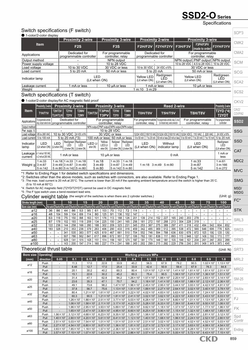
SSD2-O SeriesSpecifications
Stroke length (mm) 5 10 15 20 25 30 35 40 45 50 75 100Bore size (mm) No switch Switch No switch Switch No switch Switch No switch Switch No switch Switch No switch Switch No switch Switch No switch Switch No switch Switch No switch Switch No switch Switch No switch Switch
ø12 36 86 44 86 53 95 61 103 70 112 72 114 - - - - - - - - - - - -ø16 48 104 59 104 69 114 80 125 91 136 102 147 - - - - - - - - - - - -ø20 63 118 75 150 88 163 101 176 113 188 126 201 139 214 152 227 165 240 203 278 - - - -ø25 87 178 102 193 118 209 134 225 150 241 165 256 181 272 197 288 213 304 228 319 - - - -ø32 122 236 144 258 166 280 188 302 209 323 231 345 253 367 275 389 297 411 318 432 494 542 604 652ø40 183 326 210 353 236 379 263 406 290 433 316 459 342 485 369 512 395 538 472 565 646 695 776 825ø50 - - 341 535 383 577 425 619 467 661 510 704 552 746 594 788 636 830 678 872 1025 1082 1235 1292ø63 - - 507 786 562 841 617 896 672 951 727 1006 782 1061 838 1117 893 1172 948 1227 1438 1502 1713 1777ø80 - - 928 1341 1015 1428 1101 1514 1188 1601 1274 1687 1361 1774 1448 1861 1535 1948 1621 2034 2401 2467 2833 2899
ø100 - - 1433 2000 1547 2114 1660 2227 1774 2341 1888 2455 2002 2569 2115 2682 2229 2796 2343 2910 3406 3478 3973 4045
Cylinder weight table (the weight of the switches is when there are 2 cylinder switches.)
Switch specifications (F switch) 1-color/2-color display
ItemProximity 2-wire Proximity 3-wire Proximity 2-wire Proximity 3-wire
F2S F3S F2H/F2V F2YH/F2YV F3H/F3V F3PH/F3PV (made to order) F3YH/F3YV
Applications Dedicated for programmable controller
For programmable controller, relay
Dedicated for programmable controller
For programmable controller, relay
Output method - NPN output - NPN output PNP output NPN outputPower supply voltage - 10 to 28 VDC - 10 to 28 VDC 4.5 to 28 VDC 10 to 28 VDCLoad voltage 10 to 30 VDC 30 VDC or less 10 to 30 VDC 24 VDC ±10% 30 VDC or lessLoad current 5 to 20 mA 50 mA or less 5 to 20 mA 50 mA or less
Indicator lamp LED(Lit when ON)
Yellow LED(Lit when ON)
Red/greenLED
(Lit when ON)Yellow LED(Lit when ON)
Red/greenLED
(Lit when ON)Leakage current 1 mA or less 10 μA or less 1 mA or less 10 μA or lessWeight g 1 m:10 3 m:29
Switch specifications (T switch) 1-color/2-color display/for AC magnetic field proof
ItemProximity 2-wire Proximity 2-wire Proximity 3-wire Reed 2-wire Proximity 2-wire
T1H/T1V T2H/T2V/T2JH/T2JV
T2YH/T2YV
T2WH/ T2WV T3H/T3V T3PH/
T3PVT3YH/T3YV
T3WH/ T3WV T0H/T0V T5H/T5V T8H/T8V T2YD (*4)
T2YDTApplications For programmable controller,
relay, compact solenoid valveDedicated for
programmable controllerFor programmable
controller, relayFor programmable
controller, relayFor programmable controller, relay, IC circuit
(no indicator lamp), serial connectionFor programmable
controller, relayFor programmable
controllerOutput method - NPN output PNP output NPN output NPN output -Pwr. supp. V. - 10 to 28 VDC -Load voltage 85 to 265 VAC 10 to 30 VDC 24 VDC ±10% 30 VDC or less 12/24 VDC 100/110 VAC 5/12/24 VDC 100/110 VAC 12/24 VDC 110 VAC 220 VAC 24 VDC ±10%Load current 5 to 100 mA 5 to 20 mA (*3) 100 mA or less 50 mA or less 5 to 50 mA 7 to 20 mA 50 mA or less 20 mA or less 5 to 50 mA 7 to 20 mA 7 to 10 mA 5 to 20 mA
Indicator lamp
LED(Lit when ON)
LED (Lit when ON)
Red/green LED
(Lit when ON)
Red/green LED
(Lit when ON)LED (Lit
when ON)
Yellow LED (Lit when ON)
Red/green LED
(Lit when ON)
Red/green LED
(Lit when ON)LED
(Lit when ON)Without
indicator lampLED
(Lit when ON)Red/green
LED(Lit when ON)
Leakage current
≤ 1 mA at 100 VAC, ≤ 2 mA at 200 VAC 1 mA or less 10 μA or less 0 mA 1 mA or
less
Weight g1 m:333 m:875 m:142
1 m:183 m:495 m:80
1 m:333 m:875 m:142
1 m:183 m:495 m:80
1 m:183 m:495 m:80
1 m:333 m:875 m:142
1 m:183 m:495 m:80
1 m:18 3 m:49 5 m:801 m:333 m:875 m:142
1 m:613 m:1665 m:272
*1 : Refer to Ending Page 1 for detailed switch specifications and dimensions. *2 : Switches other than the above models, such as switches with connectors, are also available. Refer to Ending Page 1. *3 : The max. load current is 20 mA at 25°C. The current is lower than 20 mA if the operating ambient temperature around the switch is higher than 25˚C.
(5 to 10 mA at 60°C) *4 : Switch for AC magnetic field (T2YD/T2YDT) cannot be used in DC magnetic field. *5 : The F type switch uses a bend-resistant lead wire.
Theoretical thrust table (Unit: N)Bore size
(mm)Operating direction
Working pressure MPa0.05 0.1 0.15 0.2 0.3 0.4 0.5 0.6 0.7 0.8 0.9 1.0
ø12Push - 11.3 17.0 22.6 33.9 45.2 56.5 67.9 79.2 90.5 1.02×10² 1.13×10²
Pull - 8.48 12.7 17.0 25.4 33.9 42.4 50.9 59.4 67.9 76.3 84.8
ø16Push - 20.1 30.2 40.2 60.3 80.4 1.01×10² 1.21×10² 1.41×10² 1.61×10² 1.81×10² 2.01×10²
Pull - 15.1 22.6 30.2 45.2 60.3 75.4 90.5 1.06×10² 1.21×10² 1.36×10² 1.51×10²
ø20Push - 31.4 47.1 62.8 94.2 1.26×10² 1.57×10² 1.88×10² 2.20×10² 2.51×10² 2.83×10² 3.14×10²
Pull - 23.6 35.3 47.1 70.7 94.2 1.18×10² 1.41×10² 1.65×10² 1.88×10² 2.12×10² 2.36×10²
ø25Push - 49.1 73.6 98.2 1.47×10² 1.96×10² 2.45×10² 2.95×10² 3.44×10² 3.93×10² 4.42×10² 4.91×10²
Pull - 37.8 56.7 75.6 1.13×10² 1.51×10² 1.89×10² 2.27×10² 2.64×10² 3.02×10² 3.40×10² 3.78×10²
ø32Push - 80.4 1.21×10² 1.61×10² 2.41×10² 3.22×10² 4.02×10² 4.83×10² 5.63×10² 6.43×10² 7.24×10² 8.04×10²
Pull - 60.3 90.5 1.21×10² 1.81×10² 2.41×10² 3.02×10² 3.62×10² 4.22×10² 4.83×10² 5.43×10² 6.03×10²
ø40Push - 1.26×10² 1.88×10² 2.51×10² 3.77×10² 5.03×10² 6.28×10² 7.54×10² 8.80×10² 1.01×10³ 1.13×10³ 1.26×10³
Pull - 1.06×10² 1.58×10² 2.11×10² 3.17×10² 4.22×10² 5.28×10² 6.33×10² 7.39×10² 8.44×10² 9.50×10² 1.06×10³
ø50Push - 1.96×10² 2.95×10² 3.93×10² 5.89×10² 7.85×10² 9.82×10² 1.18×10³ 1.37×10³ 1.57×10³ 1.77×10³ 1.96×10³
Pull - 1.65×10² 2.47×10² 3.30×10² 4.95×10² 6.60×10² 8.25×10² 9.90×10² 1.15×10³ 1.32×10³ 1.48×10³ 1.65×10³
ø63Push 1.56×10² 3.12×10² 4.68×10² 6.23×10² 9.35×10² 1.25×10³ 1.56×10³ 1.87×10³ 2.18×10³ 2.49×10³ 2.81×10³ 3.12×10³
Pull 1.40×10² 2.80×10² 4.20×10² 5.61×10² 8.41×10² 1.12×10³ 1.40×10³ 1.68×10³ 1.96×10³ 2.24×10³ 2.52×10³ 2.80×10³
ø80Push 2.51×10² 5.03×10² 7.54×10² 1.01×10³ 1.51×10³ 2.01×10³ 2.51×10³ 3.02×10³ 3.52×10³ 4.02×10³ 4.52×10³ 5.03×10³
Pull 2.27×10² 4.54×10² 6.80×10² 9.07×10² 1.36×10³ 1.81×10³ 2.27×10³ 2.72×10³ 3.17×10³ 3.63×10³ 4.08×10³ 4.54×10³
ø100Push 3.93×10² 7.85×10² 1.18×10³ 1.57×10³ 2.36×10³ 3.14×10³ 3.93×10³ 4.71×10³ 5.50×10³ 6.28×10³ 7.07×10³ 7.85×10³
Pull 3.57×10² 7.15×10² 1.07×10³ 1.43×10³ 2.14×10³ 2.86×10³ 3.57×10³ 4.29×10³ 5.00×10³ 5.72×10³ 6.43×10³ 7.15×10³
(Unit: g)
SCP*3
CMK2
CMA2
SCM
SCG
SCA2
SCS2
CKV2
CAV2/COVP/N2
SSD2
SSG
SSD
CAT
MDC2
MVC
SMG
MSD/MSDG
FC*
STK
SRL3
SRG3
SRM3
SRT3
MRL2
MRG2
SM‑25
ShkAbs
FJ
FK
SpdContr
Ending
859

SSD2-O Series
Precautions for model No. selection*1 : The T2YD* switch cannot be mounted on the ø12
and ø16 bore sizes.*2 : The T8* switch cannot be mounted on the ø12 to
ø32 bore sizes.*3 : The F switch can only be mounted on the piping
port surface of bore sizes ø20 and ø25.*4 : Piston rod of ø12 to ø25 is stainless steel as
standard. C snap ring is stainless steel instead of steel. The rod end male thread nut is stainless steel.
*5 : The mounting bracket is included at shipment.*6 : The projection dimension of piston rod WF
when LB or FA is selected is different from that of the standard. Refer to the dimensions on pages 761, 763, 765 and 766. The number of the specified protruding dimension will be added at the end of the model No. printed on the metal plate on the body.
*7 : “I” and “Y” cannot be selected together.*8 : The F switch with L lead wire on ø20 models cannot
be selected on stroke lengths of 15 mm or under.*9 : Refer to pages 750 and 751 for combinations
of variations/options.*10 : Switches are shipped with the product. Contact
CKD if assembling before shipment is necessary.*11 : F type switch cannot be selected.
[Example of model No.]SSD2-OL-12-10-T0H-R-N-LB-IModel: Compact cylinder double acting/low speedB Bore size : ø12 mmC Port thread : Rc threadD Stroke length : 10mmE Switch model No. : Reed switch T0H, lead
wire length 1 mF Switch quantity : 1 on rod sideG Option : Rod end male threadH Mounting bracket : Axial footI Accessory : Rod eye
Model No.A
Accessory *7
I
G
How to orderWithout switch (without magnet for switch)
With switch (built-in magnet for switch)
12 IN5
Mounting bracket *5*6
H
Switch quantityF
*1*2*3*8*10
Switch model No.E
Stroke lengthD
Port threadC
Bore sizeB
12 R10 IN
Option*4
SSD2-O LB
LBT0HSSD2-OL
Code DescriptionModel No.
SSD2-O Double acting/single rodSSD2-OL Double acting/single rod/with switch
Bore size (mm)12 ø1216 ø1620 ø2025 ø2532 ø3240 ø4050 ø5063 ø6380 ø80
100 ø100
Port threadBlank Rc thread
NN NPT thread (ø32 and over) (made-to-order product)GN G thread (ø32 and over) (made-to-order product)
Stroke length (mm)Refer to the stroke length table on the following page.
* Lead wire lengthBlank 1 m (standard)
3 3 m (option)5 5 m (option) *11
Switch quantityR 1 on rod sideH 1 on head sideD 2
OptionBlank Rod end female thread
N Rod end male threadM *4 Piston rod material (stainless steel)
Mounting bracketBlank Without mounting bracket
LB Axial footCB Clevis bracket (pin and snap ring included)FA Rod side flangeFB Head side flange
Accessory (available when rod end male thread “N” is selected)I Rod eyeY Rod clevis (pin and snap ring included)
A
B
C
D
F
G
I
H
Switch model No.Lead wire Lead wire
Conta
ct Voltage DisplayLead wire
Bore sizeStraight L-shaped AC DC 12 16 20 25 32 40 50 63 80 100
- F2S*
Pro
xim
ity
1-color display
2-wire - F3S* 3-wire
F2H* F2V* 2-wire F3H* F3V* 3-wire
F3PH* F3PV* 1 color display (PNP output) (custom) 3-wire F2YH* F2YV*
2-color display2-wire
F3YH* F3YV* 3-wire T0H* T0V*
Ree
d 1-color display2-wire
T5H* T5V* Without indicator lamp T8H* T8V* 1-color display T1H* T1V*
Pro
xim
ity
1-color display
2-wire
T2H* T2V* T3H* T3V*
3-wire
T3PH* T3PV* 1-color display (PNP output) T2WH* T2WV*
2-color display2-wire
T2YH* T2YV* T3WH* T3WV*
3-wire
T3YH* T3YV* T2YD* - 2-color display
for AC magnetic field 2-wire
T2YDT* - T2JH* T2JV* 1-color display off-delay 2-wire
E
SCP*3
CMK2
CMA2
SCM
SCG
SCA2
SCS2
CKV2
CAV2/COVP/N2
SSD2
SSG
SSD
CAT
MDC2
MVC
SMG
MSD/MSDG
FC*
STK
SRL3
SRG3
SRM3
SRT3
MRL2
MRG2
SM‑25
ShkAbs
FJ
FK
SpdContr
Ending
860

Stroke length (mm)Applicable bore size
12 16 20 25 32 40 50 63 80 100
Sta
ndar
d st
roke
leng
th
5 10 15 20 25 30 35 40 45 50 75
100 Min. stroke length (mm) *1 1Max. stroke length (mm) 30 50 100Custom stroke length *2 In 1 mm increments
*1 : Less than 5 mm for 1-color display switch and less than 10 mm for the 2-color display, off-delay, AC magnetic field proof, T1* or T8* switch are not available. Refer to page 858 for the min. stroke length with switch.
*2 : The total length when using a custom stroke length is the same as that when using the next longer standard stroke length.
*3 : Refer to pages 763 and 765 for the min. stroke length with mounting bracket LB.
Bore size (mm)ø12 ø16 ø20 ø25 ø32 ø40 ø50
Mounting bracketFoot (LB) SSD2-LB-12 SSD2-LB-16 SSD2-LB-20 SSD2-LB-25 SSD2-LB-32 SSD2-LB-40 SSD2-LB-50Flange (FA/FB) SSD2-FA-12 SSD2-FA-16 SSD2-FA-20 SSD2-FA-25 SSD2-FA-32 SSD2-FA-40 SSD2-FA-50Clevis bracket (CB) SSD2-CB-12 SSD2-CB-16 SSD2-CB-20 SSD2-CB-25 SSD2-CB-32 SSD2-CB-40 SSD2-CB-50
Bore size (mm)ø63 ø80 ø100
Mounting bracketFoot (LB) SSD2-LB-63 SSD2-LB-80 SSD2-LB-100Flange (FA/FB) SSD2-FA-63 SSD2-FA-80 SSD2-FA-100Clevis bracket (CB) SSD2-CB-63 SSD2-CB-80 SSD2-CB-100
SSD2-O SeriesHow to order
*1: The foot mounting bracket is provided as 2 pcs./set.
[Stroke length table]
How to order mounting bracket
Dimensions
Same as SSD2 Series (double acting/single rod). Refer to pages 760 to 766.
How to order switch
Switch model No. (Item E on page 860)
SW T0H
SCP*3
CMK2
CMA2
SCM
SCG
SCA2
SCS2
CKV2
CAV2/COVP/N2
SSD2
SSG
SSD
CAT
MDC2
MVC
SMG
MSD/MSDG
FC*
STK
SRL3
SRG3
SRM3
SRT3
MRL2
MRG2
SM‑25
ShkAbs
FJ
FK
SpdContr
Ending
861

Internal structure and parts list (ø12 to 50) SSD2-O-L-12 to 25 (double acting/with switch)
SSD2-O Series
SSD2-O-L-32 to 50 (double acting/with switch)
SSD2-O-12 to 25 (double acting) SSD2-O-32 to 50 (double acting)
No. Part name Material Remarks No. Part name Material Remarks
1 Piston rod ø12 to ø25: Stainless steel ø32 to ø50: Steel
ø16 to ø50:Industrial chrome plating 7 Spacer Aluminum alloy ø12 to ø32: Chromate
2 C snap ring Steel Zinc phosphate 8 Magnet Plastic
3 Rod metal Special aluminum Alumite 9 Piston Aluminum alloy Chromate
4 Rod metal gasket Nitrile rubber 10 Piston packing Nitrile rubber
5 Body Aluminum alloy Hard alumite11 Cover ø12 to ø25: Stainless steel
ø32 to ø50: Aluminum alloy ø32 to ø50: Alumite6 Rod packing Nitrile rubber
Bore size (mm) Kit No. Repair parts No.ø12 SSD2-O-12K
4 6 10
ø16 SSD2-O-16Kø20 SSD2-O-20Kø25 SSD2-O-25Kø32 SSD2-O-32Kø40 SSD2-O-40Kø50 SSD2-O-50K
Repair parts list
1 2 3 4 5 6 7 8 10 9 11 1 2 3 4 5 6 7 8 10 9 11
1 2 3 4 5 6 9 10 11 1 2 3 4 5 6 9 10 11
SCP*3
CMK2
CMA2
SCM
SCG
SCA2
SCS2
CKV2
CAV2/COVP/N2
SSD2
SSG
SSD
CAT
MDC2
MVC
SMG
MSD/MSDG
FC*
STK
SRL3
SRG3
SRM3
SRT3
MRL2
MRG2
SM‑25
ShkAbs
FJ
FK
SpdContr
Ending
862

SSD2-O SeriesInternal structure and parts list
Internal structure and parts list (ø63 to ø100) SSD2-O-L-63 to 100 (double acting/with switch)
SSD2-O-63 to 100 (double acting)
No. Part name Material Remarks No. Part name Material Remarks1 Piston rod Steel Industrial chrome plating 7 Spacer Aluminum alloy
2 C snap ring Steel Zinc phosphate 8 Magnet Plastic
3 Rod metal Aluminum alloy Chromate 9 Piston Aluminum alloy Chromate
4 Rod metal gasket Nitrile rubber 10 Piston packing Nitrile rubber
5 Body Aluminum alloy Hard alumite 11 Cover Aluminum alloy Alumite
6 Rod packing Nitrile rubber 12 Bush Oiles drymet *1
Bore size (mm) Kit No. Repair parts No.ø63 SSD2-O-63K
4 6 10ø80 SSD2-O-80Kø100 SSD2-O-100K
Repair parts list
*1: Material is steel for copper and PTFE free specifications.
6 21 3 4 12 5 7 8 10 9 11
1 6 2 3 4 12 5 9 10 11
SCP*3
CMK2
CMA2
SCM
SCG
SCA2
SCS2
CKV2
CAV2/COVP/N2
SSD2
SSG
SSD
CAT
MDC2
MVC
SMG
MSD/MSDG
FC*
STK
SRL3
SRG3
SRM3
SRT3
MRL2
MRG2
SM‑25
ShkAbs
FJ
FK
SpdContr
Ending
863

Compact cylinder double acting/high load/low friction
SSD2-KU Series Bore size: ø20/ø25/ø32/ø40
ø50/ø63/ø80/ø100JIS symbol
SpecificationsItem
SSD2-KU SSD2-KUL (with switch)
Bore size mm ø20 ø25 ø32 ø40 ø50 ø63 ø80 ø100Actuation Double actingWorking fluid Compressed airMax. working pressure MPa 0.7 (≈100 psi, 7 bar)Min. working pressure MPa 0.03 (≈4.4 psi, 0.3 bar)Proof pressure MPa 1.0 (≈150 psi, 10 bar)Ambient temperature °C 5 (41°F) to 60 (140°F)Port size M5 Rc1/8 Rc1/4 Rc3/8
Stroke tolerance mm+2.0
0Working piston speed mm/s 10 to 500 10 to 300Cushion Rubber cushionLubrication Not availableAllowable absorbed energy J 0.16 0.16 0.40 0.63 0.98 1.56 2.51 3.92Internal leakage ℓ/min 5 8
Custom stroke length SSD2-KU Series
ItemStandard products
Standard stroke length body with spacerModel No. Refer to How to order.
DescriptionA spacer is added to the standard stroke length body to adjust the stroke length in 1 mm increments.
Stroke rangeBore size Stroke range20 to 25 1 to 4932 to 100 1 to 99
Example of model No.
Model No.: SSD2-KU-32-41A +4 mm spacer is added to the SSD2-KU-32-45 standard cylinder to create 41 mm stroke length.B + stroke length is 78mm.
Stroke length
*1 : When using the type with switch, refer to the table of the min. stroke length with switch.*2 : Refer to page 789 for the min. stroke length with mounting bracket LB.
Bore size(mm)
Standard stroke length (mm)
Max. stroke length (mm)
Min. stroke length (mm)
ø20 5/10/15/20/2530/35/40/45/50
50
5
ø25ø32 5/10/15/20/25/30/
35/40/45/50/75/100
100
ø40ø50
10/15/20/2530/35/40/45/50
75/100
ø63ø80ø100
Min. stroke length with switch (1 or 2 switches)
*1: Less than 10 mm with the 2-color display, off-delay, AC magnetic field proof, T1* or T8* switch is not available.
Bore size(mm) T0H/V / T5H/V T2H/V / T3H/V
ø20
5 5
ø25ø32ø40ø50ø63ø80ø100
A + stroke length
B + stroke length
SCP*3
CMK2
CMA2
SCM
SCG
SCA2
SCS2
CKV2
CAV2/COVP/N2
SSD2
SSG
SSD
CAT
MDC2
MVC
SMG
MSD/MSDG
FC*
STK
SRL3
SRG3
SRM3
SRT3
MRL2
MRG2
SM‑25
ShkAbs
FJ
FK
SpdContr
Ending
864

SSD2-KU SeriesSpecifications
Switch specifications (F switch) 1-color/2-color display
ItemProximity 2-wire Proximity 3-wire Proximity 2-wire Proximity 3-wire
F2S F3S F2H/F2V F2YH/F2YV F3H/F3VF3PH/F3PV
(made to order)F3YH/F3YV
Applications Dedicated for programmable controller
For programmable controller, relay
Dedicated for programmable controller
For programmable controller, relay
Output method - NPN output - NPN output PNP output NPN outputPower supply voltage - 10 to 28 VDC - 10 to 28 VDC 4.5 to 28 VDC 10 to 28 VDCLoad voltage 10 to 30 VDC 30 VDC or less 10 to 30 VDC 24 VDC ±10% 30 VDC or lessLoad current 5 to 20 mA 50 mA or less 5 to 20 mA 50 mA or less
Indicator lamp LED(Lit when ON)
Yellow LED(Lit when ON)
Red/greenLED
(Lit when ON)
Yellow LED(Lit when ON)
Red/greenLED
(Lit when ON)Leakage current 1 mA or less 10 μA or less 1 mA or less 10 μA or lessWeight g 1 m:10 3 m:29
Switch specifications (T switch) 1-color/2-color display/for AC magnetic field proof
ItemProximity 2-wire Proximity 2-wire Proximity 3-wire Reed 2-wire Proximity 2-wire
T1H/T1VT2H/T2V/
T2JH/T2JVT2YH/T2YV
T2WH/ T2WV
T3H/T3VT3PH/T3PV
T3YH/T3YV
T3WH/ T3WV
T0H/T0V T5H/T5V T8H/T8VT2YD(*4)T2YDT
ApplicationsFor programmable
controller, relay, compact solenoid valve
Dedicated for programmable controller
For programmable controller, relay
For programmable controller, relay
For programmable controller, relay, IC circuit (no indicator lamp), serial connection
For programmable controller, relay
For programmable
controllerOutput method - NPN output PNP output NPN output NPN output -Pwr. supp. V. - 10 to 28 VDC -Load voltage 85 to 265 VAC 10 to 30 VDC 24 VDC ±10% 30 VDC or less 12/24 VDC 100/110 VAC 5/12/24 VDC 100/110 VAC 12/24 VDC 110 VAC 220 VAC 24 VDC ±10%Load current 5 to 100 mA 5 to 20 mA (*3) 100 mA or less 50 mA or less 5 to 50 mA 7 to 20 mA 50 mA or less 20 mA or less 5 to 50 mA 7 to 20 mA 7 to 10 mA 5 to 20 mA
Indicator lamp
LED(Lit when
ON)
LED (Lit when ON)
Red/green LED
(Lit when ON)
Red/green LED
(Lit when ON)
LED (Lit when ON)
Yellow LED (Lit
when ON)
Red/green LED
(Lit when ON)
Red/green LED
(Lit when ON)
LED(Lit when ON)
Without indicator lamp
LED(Lit when ON)
Red/green LED
(Lit when ON)Leakage current
≤ 1 mA at 100 VAC, ≤ 2 mA at 200 VAC
1 mA or less 10 μA or less 0 mA1 mA or
less
Weight g1 m:333 m:875 m:142
1 m:183 m:495 m:80
1 m:333 m:875 m:142
1 m:183 m:495 m:80
1 m:183 m:495 m:80
1 m:333 m:875 m:142
1 m:183 m:495 m:80
1 m:18 3 m:49 5 m:801 m:333 m:875 m:142
1 m:613 m:1665 m:272
*1 : Refer to Ending Page 1 for detailed switch specifications and dimensions. *2 : Switches other than the above models, such as switches with connectors, are also available. Refer to Ending Page 1. *3 : The max. load current is 20 mA at 25°C. The current is lower than 20 mA if the operating ambient temperature around the switch is higher than 25˚C.
(5 to 10 mA at 60°C) *4 : Switch for AC magnetic field (T2YD/T2YDT) cannot be used in DC magnetic field. *5 : The F type switch uses a bend-resistant lead wire.
Bore size (mm)
Operating direction
Working pressure MPa0.03 0.1 0.15 0.2 0.3 0.4 0.5 0.6 0.7
ø20Push 9.42 31.4 47.1 62.8 94.2 1.26×10² 1.57×10² 1.88×10² 2.20×10²
Pull 7.07 23.6 35.3 47.1 70.7 94.2 1.18×10² 1.41×10² 1.65×10²
ø25Push 14.7 49.1 73.6 98.2 1.47×10² 1.96×10² 2.45×10² 2.95×10² 3.44×10²
Pull 11.3 37.8 56.7 75.6 1.13×10² 1.51×10² 1.89×10² 2.27×10² 2.64×10²
ø32Push 24.1 80.4 1.21×10² 1.61×10² 2.41×10² 3.22×10² 4.02×10² 4.83×10² 5.63×10²
Pull 18.1 60.3 90.5 1.21×10² 1.81×10² 2.41×10² 3.02×10² 3.62×10² 4.22×10²
ø40Push 37.7 1.26×10² 1.88×10² 2.51×10² 3.77×10² 5.03×10² 6.28×10² 7.54×10² 8.80×10²
Pull 31.7 1.06×10² 1.58×10² 2.11×10² 3.17×10² 4.22×10² 5.28×10² 6.33×10² 7.39×10²
ø50Push 58.9 1.96×10² 2.95×10² 3.93×10² 5.89×10² 7.85×10² 9.82×10² 1.18×10³ 1.37×10³
Pull 49.5 1.65×10² 2.47×10² 3.30×10² 4.95×10² 6.60×10² 8.25×10² 9.90×10² 1.15×10³
ø63Push 93.5 3.12×10² 4.68×10² 6.23×10² 9.35×10² 1.25×10³ 1.56×10³ 1.87×10³ 2.18×10³
Pull 84.0 2.80×10² 4.20×10² 5.61×10² 8.41×10² 1.12×10³ 1.40×10³ 1.68×10³ 1.96×10³
ø80Push 1.51×10² 5.03×10² 7.54×10² 1.01×10³ 1.51×10³ 2.01×10³ 2.51×10³ 3.02×10³ 3.52×10³
Pull 1.36×10² 4.54×10² 6.80×10² 9.07×10² 1.36×10³ 1.81×10³ 2.27×10³ 2.72×10³ 3.17×10³
ø100Push 2.36×10² 7.85×10² 1.18×10³ 1.57×10³ 2.36×10³ 3.14×10³ 3.93×10³ 4.71×10³ 5.50×10³
Pull 2.14×10² 7.15×10² 1.07×10³ 1.43×10³ 2.14×10³ 2.86×10³ 3.57×10³ 4.29×10³ 5.00×10³
Theoretical thrust table (Unit: N)
SCP*3
CMK2
CMA2
SCM
SCG
SCA2
SCS2
CKV2
CAV2/COVP/N2
SSD2
SSG
SSD
CAT
MDC2
MVC
SMG
MSD/MSDG
FC*
STK
SRL3
SRG3
SRM3
SRT3
MRL2
MRG2
SM‑25
ShkAbs
FJ
FK
SpdContr
Ending
865

A
C
E
Option *2
F
Mounting bracket*3*4
G
D Switch model No. *1*6*8
Port threadB
Bore size
Stroke length
Precautions for model No. selection*1 : The F switch can only be mounted on the piping port
surface of bore sizes ø20 and ø25.*2 : Piston rod of ø20 and ø25 is stainless steel as
standard. C snap ring is stainless steel instead of steel. The rod end male thread nut is stainless steel.
*3 : The mounting bracket is included at shipment.*4 : The projection dimension of piston rod WF when LB
or FA is selected is different from that of the standard. Refer to the dimensions on pages 783, 785, 787, 789 and 790. The number of the specified protruding dimension will be added at the end of the model No. printed on the metal plate on the body.
*5 : “I” and “Y” cannot be selected together.*6 : The F switch with L lead wire on ø20 models cannot
be selected on stroke lengths 10 mm or under.*7 : Refer to pages 750 and 751 for combinations
of variations/options.*8 : Switches are shipped with the product. Contact CKD if
assembling before shipment is necessary.*9 : F type switch cannot be selected.
[Example of model No.]SSD2-KUL-20-10-T0H-R-NModel: Compact cylinder, high load/low frictionA Bore size : ø20 mmB Port thread : Rc threadC Stroke length : 10mmD Switch model No. : Reed T0H switch · Lead wire 1 mE Switch quantity : 1 on rod sideF Option : Rod end male thread
Accessory *5
H
Switch quantity
SSD2-KU Series
How to orderWithout switch (without magnet for switch)
With switch (built-in magnet for switch)
20
T0H R N I
IN10
20 10
SSD2-KU LB
LBSSD2-KUL
Code DescriptionBore size (mm)
20 ø2025 ø2532 ø3240 ø4050 ø5063 ø6380 ø80
100 ø100
Port threadBlank Rc thread
NN NPT thread (ø32 and over) (made-to-order product)GN G thread (ø32 and over) (made-to-order product)
Stroke length (mm)Refer to the stroke length table on the following page.
* Lead wire lengthBlank 1 m (standard)
3 3 m (option)5 5 m (option) *9
Switch quantityR 1 on rod sideH 1 on head sideD 2
OptionBlank Rod end female thread
N Rod end male threadM *2 Piston rod material (stainless steel)
Mounting bracketBlank Without mounting bracket
LB Axial footCB Clevis bracket (pin and snap ring included)FA Rod side flangeFB Head side flange
Accessory (available when rod end male thread “N” is selected)I Rod eyeY Rod clevis (pin and snap ring included)
Switch model No.Lead wire Lead wire
Cont
act
VoltageDisplay
Lead wire
Bore sizeStraight L-shaped AC DC 20 25 32 40 50 63 80 100
- F2S*
Pro
xim
ity
1-color display
2-wire
- F3S* 3-wire
F2H* F2V* 2-wire
F3H* F3V* 3-wire
F3PH* F3PV* 1 color display (PNP output) (custom) 3-wire
F2YH* F2YV* 2-color display
2-wire
F3YH* F3YV* 3-wire
T0H* T0V*
Ree
d 1-color display2-wire
T5H* T5V* Without indicator lamp
T8H* T8V* 1-color display
T1H* T1V*
Pro
xim
ity
1-color display
2-wire
T2H* T2V*
T3H* T3V* 3-wire
T3PH* T3PV* 1-color display (PNP output)
T2WH* T2WV*
2-color display2-wire
T2YH* T2YV*
T3WH* T3WV* 3-wire
T3YH* T3YV*
T2YD* - 2-color display for AC magnetic field 2-wire
T2YDT* -
T2JH* T2JV* 1-color display off-delay 2-wire
A
C
E
F
G
H
D
B
SCP*3
CMK2
CMA2
SCM
SCG
SCA2
SCS2
CKV2
CAV2/COVP/N2
SSD2
SSG
SSD
CAT
MDC2
MVC
SMG
MSD/MSDG
FC*
STK
SRL3
SRG3
SRM3
SRT3
MRL2
MRG2
SM‑25
ShkAbs
FJ
FK
SpdContr
Ending
866

SSD2-KU SeriesHow to order
[Stroke length table]
*1 : Less than 10 mm with the 2-color display, off-delay, strong magnetic field proof, T1* or T8* switch is not available. Refer to page 864 for the min. stroke length with switch.
*2 : The total length is the same as that of the next longer standard stroke length.*3 : Refer to page 789 for the min. stroke length with mounting bracket LB.
How to order mounting bracketBore size (mm)
ø20 ø25 ø32 ø40 ø50 ø63 ø80 ø100Mounting bracketFoot (LB) SSD2-LB-20 SSD2-LB-25 SSD2-LB-32 SSD2-LB-40 SSD2-LB-50 SSD2-LB-63 SSD2-LB-80 SSD2-LB-100Flange (FA/FB) SSD2-FA-20 SSD2-FA-25 SSD2-FA-32 SSD2-FA-40 SSD2-FA-50 SSD2-FA-63 SSD2-FA-80 SSD2-FA-100Clevis bracket (CB) SSD2-CB-20 SSD2-CB-25 SSD2-CB-32 SSD2-CB-40 SSD2-CB-50 SSD2-CB-63 SSD2-CB-80 SSD2-CB-100*1: The foot mounting bracket is provided as 2 pcs./set.
Stroke length (mm)Applicable bore size
ø20 ø25 ø32 ø40 ø50 ø63 ø80 ø100
Sta
ndar
d st
roke
leng
th
5 10 15 20 25 30 35 40 45 50 75
100 Min. stroke length (mm) 5Max. stroke length (mm) 50 100Custom stroke length *2 In 1 mm increments
Dimensions
Same as SSD2-K Series (double acting/high load). Refer to pages 782 to 790.
Technical data
Refer to SCM-U Series on page 306 for technical data regarding sliding resistance values.SSD2-KU Series shows a similar trend to the data of “SCM-U Series”.
SCP*3
CMK2
CMA2
SCM
SCG
SCA2
SCS2
CKV2
CAV2/COVP/N2
SSD2
SSG
SSD
CAT
MDC2
MVC
SMG
MSD/MSDG
FC*
STK
SRL3
SRG3
SRM3
SRT3
MRL2
MRG2
SM‑25
ShkAbs
FJ
FK
SpdContr
Ending
867
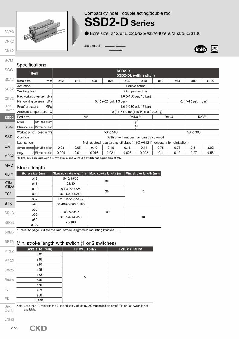
Compact cylinder double acting/double rod
SSD2-D Series Bore size: ø12/ø16/ø20/ø25/ø32/ø40/ø50/ø63/ø80/ø100
Specifications
*1: The ø32 bore size with a 5 mm stroke and without a switch has a port size of M5.
Item SSD2-DSSD2-DL (with switch)
Bore size mm ø12 ø16 ø20 ø25 ø32 ø40 ø50 ø63 ø80 ø100Actuation Double actingWorking fluid Compressed airMax. working pressure MPa 1.0 (≈150 psi, 10 bar)Min. working pressure MPa 0.15 (≈22 psi, 1.5 bar) 0.1 (≈15 psi, 1 bar)Proof pressure MPa 1.6 (≈230 psi, 16 bar)Ambient temperature °C -10 (14°F) to 60 (140°F) (no freezing)Port size M5 Rc1/8 *1 Rc1/4 Rc3/8Stroke tolerance mm
With rubber cushion +2.00
Without cushion +1.00
Working piston speed mm/s 50 to 500 50 to 300Cushion With or without cushion can be selectedLubrication Not required (use turbine oil class 1 ISO VG32 if necessary for lubrication)Allowable absorbed With rubber cushion 0.03 0.05 0.10 0.16 0.16 0.44 0.75 0.78 2.51 3.92energy J Without cushion 0.004 0.01 0.016 0.021 0.025 0.092 0.1 0.12 0.27 0.56
Stroke lengthBore size (mm) Standard stroke length (mm) Max. stroke length (mm) Min. stroke length (mm)
ø12 5/10/15/2025/30
30
5
ø16ø20 5/10/15/20/25
30/35/40/45/5050
ø25ø32 5/10/15/20/25/30/
35/40/45/50/75/100
100
ø40ø50
10/15/20/2530/35/40/45/50
75/10010
ø63ø80ø100
Min. stroke length with switch (1 or 2 switches)
Note: Less than 10 mm with the 2-color display, off-delay, AC magnetic field proof, T1* or T8* switch is not available.
Bore size (mm) T0H/V / T5H/V T2H/V / T3H/Vø12
5 5
ø16ø20ø25ø32ø40ø50ø63ø80ø100
JIS symbol
*: Refer to page 881 for the min. stroke length with mounting bracket LB.
SCP*3
CMK2
CMA2
SCM
SCG
SCA2
SCS2
CKV2
CAV2/COVP/N2
SSD2
SSG
SSD
CAT
MDC2
MVC
SMG
MSD/MSDG
FC*
STK
SRL3
SRG3
SRM3
SRT3
MRL2
MRG2
SM‑25
ShkAbs
FJ
FK
SpdContr
Ending
868

SSD2-D SeriesSpecifications
Switch specifications (F switch) 1-color/2-color display
ItemProximity 2-wire Proximity 3-wire Proximity 2-wire Proximity 3-wire
F2S F3S F2H/F2V F2YH/F2YV F3H/F3VF3PH/F3PV
(made to order)F3YH/F3YV
Applications Dedicated for programmable controller
For programmable controller, relay
Dedicated for programmable controller
For programmable controller, relay
Output method - NPN output - NPN output PNP output NPN outputPower supply voltage - 10 to 28 VDC - 10 to 28 VDC 4.5 to 28 VDC 10 to 28 VDCLoad voltage 10 to 30 VDC 30 VDC or less 10 to 30 VDC 24 VDC ±10% 30 VDC or lessLoad current 5 to 20 mA 50 mA or less 5 to 20 mA 50 mA or less
Indicator lamp LED(Lit when ON)
Yellow LED(Lit when ON)
Red/greenLED
(Lit when ON)
Yellow LED(Lit when ON)
Red/greenLED
(Lit when ON)Leakage current 1 mA or less 10 μA or less 1 mA or less 10 μA or lessWeight g 1 m:10 3 m:29
Switch specifications (T switch) 1-color/2-color display/for AC magnetic field proof
ItemProximity 2-wire Proximity 2-wire Proximity 3-wire Reed 2-wire Proximity 2-wire
T1H/T1VT2H/T2V/
T2JH/T2JVT2YH/T2YV
T2WH/ T2WV
T3H/T3VT3PH/T3PV
T3YH/T3YV
T3WH/ T3WV
T0H/T0V T5H/T5V T8H/T8VT2YD(*4)T2YDT
ApplicationsFor programmable
controller, relay, compact solenoid valve
Dedicated for programmable controller
For programmable controller, relay
For programmable controller, relay
For programmable controller, relay, IC circuit (no indicator
lamp), serial connection
For programmable controller, relay
For programmable
controllerOutput method - NPN output PNP output NPN output NPN output -Pwr. supp. V. - 10 to 28 VDC -Load voltage 85 to 265 VAC 10 to 30 VDC 24 VDC ±10% 30 VDC or less 12/24 VDC 100/110 VAC 5/12/24 VDC 100/110 VAC 12/24 VDC 110 VAC 220 VAC 24 VDC ±10%Load current 5 to 100 mA 5 to 20 mA (*3) 100 mA or less 50 mA or less 5 to 50 mA 7 to 20 mA 50 mA or less 20 mA or less 5 to 50 mA 7 to 20 mA 7 to 10 mA 5 to 20 mA
Indicator lamp
LED(Lit when
ON)
LED (Lit when ON)
Red/green LED
(Lit when ON)
Red/green LED
(Lit when ON)
LED (Lit when ON)
Yellow LED (Lit
when ON)
Red/green LED
(Lit when ON)
Red/green LED
(Lit when ON)
LED(Lit when ON)
Without indicator lamp
LED(Lit when ON)
Red/green LED
(Lit when ON)Leakage current
≤ 1 mA at 100 VAC, ≤ 2 mA at 200 VAC
1 mA or less 10 μA or less 0 mA1 mA or
less
Weight g1 m:333 m:875 m:142
1 m:183 m:495 m:80
1 m:333 m:875 m:142
1 m:183 m:495 m:80
1 m:183 m:495 m:80
1 m:333 m:875 m:142
1 m:183 m:495 m:80
1 m:18 3 m:49 5 m:801 m:333 m:875 m:142
1 m:613 m:1665 m:272
*1 : Refer to Ending Page 1 for detailed switch specifications and dimensions. *2 : Switches other than the above models, such as switches with connectors, are also available. Refer to Ending Page 1. *3 : The max. load current is 20 mA at 25°C. The current is lower than 20 mA if the operating ambient temperature around the switch is higher than 25˚C.
(5 to 10 mA at 60°C) *4 : Switch for AC magnetic field (T2YD/T2YDT) cannot be used in DC magnetic field. *5 : The F type switch uses a bend-resistant lead wire.
Theoretical thrust tableBore size
(mm)Operating direction
Working pressure MPa0.1 0.15 0.2 0.3 0.4 0.5 0.6 0.7 0.8 0.9 1.0
ø12 Push/Pull - 12.7 17.0 25.4 33.9 42.4 50.9 59.4 67.9 76.3 84.8ø16 Push/Pull - 22.6 30.2 45.2 60.3 75.4 90.5 1.06× 10² 1.21× 10² 1.36× 10² 1.51× 10²
ø20 Push/Pull - 35.3 47.1 70.7 94.2 1.18× 10² 1.41× 10² 1.65× 10² 1.88× 10² 2.12× 10² 2.36× 10²
ø25 Push/Pull - 56.7 75.6 1.13× 10² 1.51× 10² 1.89× 10² 2.27× 10² 2.64× 10² 3.02× 10² 3.40× 10² 3.78× 10²
ø32 Push/Pull - 90.5 1.21× 10² 1.81× 10² 2.41× 10² 3.02× 10² 3.62× 10² 4.22× 10² 4.83× 10² 5.43× 10² 6.03× 10²
ø40 Push/Pull - 1.58× 10² 2.11× 10² 3.17× 10² 4.22× 10² 5.28× 10² 6.33× 10² 7.39× 10² 8.44× 10² 9.50× 10² 1.06× 10³
ø50 Push/Pull - 2.47× 10² 3.30× 10² 4.95× 10² 6.60× 10² 8.25× 10² 9.90× 10² 1.15× 10³ 1.32× 10³ 1.48× 10³ 1.65× 10³
ø63 Push/Pull 2.80× 10² 4.20× 10² 5.61× 10² 8.41× 10² 1.12× 10³ 1.40× 10³ 1.68× 10³ 1.96× 10³ 2.24× 10³ 2.52× 10³ 2.80× 10³
ø80 Push/Pull 4.54× 10² 6.80× 10² 9.07× 10² 1.36× 10³ 1.81× 10³ 2.27× 10³ 2.72× 10³ 3.17× 10³ 3.63× 10³ 4.08× 10³ 4.54× 10³
ø100 Push/Pull 7.15× 10² 1.07× 10³ 1.43× 10³ 2.14× 10³ 2.86× 10³ 3.57× 10³ 4.29× 10³ 5.00× 10³ 5.72× 10³ 6.43× 10³ 7.15× 10³
(Unit: N)
Stroke length (mm) 5 10 15 20 25 30 35 40 45 50 75 100Bore size (mm) No switch Switch No switch Switch No switch Switch No switch Switch No switch Switch No switch Switch No switch Switch No switch Switch No switch Switch No switch Switch No switch Switch No switch Switch
ø12 52 105 60 105 69 115 77 124 86 134 95 147 - - - - - - - - - - - -ø16 74 133 85 133 95 144 106 156 117 168 128 177 - - - - - - - - - - - -ø20 131 187 143 222 161 238 179 254 196 269 214 285 232 301 249 316 267 332 284 347 - - - -ø25 147 238 162 253 178 269 194 285 210 301 226 316 242 332 257 348 275 364 288 379 - - - -ø32 184 299 230 344 275 390 322 436 366 481 413 527 459 573 469 612 485 628 522 665 776 785 1004 1012ø40 283 426 310 453 336 479 363 506 390 533 416 569 443 601 507 617 553 663 601 707 1317 1333 1475 1490ø50 - - 508 702 558 751 608 803 658 851 708 901 758 950 808 1001 835 1033 911 1105 2007 2025 2252 2270ø63 - - 902 1266 977 1341 1052 1416 1127 1491 1202 1566 1278 1642 1353 1717 1428 1792 1503 1867 2218 2242 2593 2617ø80 - - 1608 1538 1725 1916 1841 2294 1958 2411 2074 2527 2191 2649 2308 2771 2425 2888 2541 3004 3560 3587 4143 4169
ø100 - - 2483 3105 2652 3254 2820 3402 2989 3586 3158 3770 3327 3934 3495 4097 3664 4261 3833 4425 5213 5245 6033 6065
Cylinder weight table (the weight of the switches is when there are 2 cylinder switches.) (Unit: g)
SCP*3
CMK2
CMA2
SCM
SCG
SCA2
SCS2
CKV2
CAV2/COVP/N2
SSD2
SSG
SSD
CAT
MDC2
MVC
SMG
MSD/MSDG
FC*
STK
SRL3
SRG3
SRM3
SRT3
MRL2
MRG2
SM‑25
ShkAbs
FJ
FK
SpdContr
Ending
869

SSD2-D Series
Model No.A
Accessory *7
J
How to orderWithout switch (without magnet for switch)
With switch (built-in magnet for switch)
12 IN5
Bore sizeB
12
Switch quantityG
*1, *2*3, *8*9
F Switch model No.
Option *4H
CushionD
Stroke lengthE
Port threadC
R IN10
Precautions for model No. selection*1 : The T2YD* switch cannot be mounted on the ø12 and
ø16 bore sizes.*2 : The T8* switch cannot be mounted on ø12 and ø16.*3 : The F switch can only be mounted on the piping port
surface of bore sizes ø20 and ø25.*4 : Piston rod of ø12 to ø25 is stainless steel as standard.
C snap ring is stainless steel instead of steel. The rod end male thread nut is stainless steel.
*5 : The mounting bracket is included at shipment.*6 : The projection dimension of piston rod WF
when LB or FA is selected is different from that of the standard. Refer to the dimensions on pages 877, 879 and 881. The number of the specified protruding dimension will be added at the end of the model No. printed on the metal plate on the body.
*7 : ”I” and “Y” cannot be selected together.*8 : The F switch with L type lead wire on ø20 models
cannot be selected on stroke lengths of 15 mm or under.
*9 : Switches are shipped with the product. Contact CKD if assembling before shipment is necessary.
*10 : Refer to pages 750 and 751 for combinations of variations/options.
*11 : F type switch cannot be selected.
[Example of model No.]SSD2-DL-12-5-T0H-R-N-LB-IModel: Compact cylinder double acting/double rodB Bore size : ø12 mmC Port thread : Rc threadD Cushion : No cushionE Stroke length : 5mmF Switch model No. : Reed T0H switch/
Lead wire length 1 mG Switch quantity : 1 on rod sideH Option : Rod end male threadI Mounting bracket : Axial footJ Accessory : Rod eye
How to order switch
Switch model No. (Item F above)
SSD2-D LB
LBT0HSSD2-DL
SW T0H
Code DescriptionModel No.
SSD2-D Double acting/double rodSSD2-DL Double acting/double rod/with switch
Bore size (mm)12 ø1216 ø1620 ø2025 ø2532 ø3240 ø4050 ø5063 ø6380 ø80
100 ø100
Port threadBlank Rc thread
NN NPT thread (ø32 and over) (made-to-order product)GN G thread (ø32 and over) (made-to-order product)
CushionBlank Without cushion
D With rubber cushion
Stroke length (mm)Refer to the stroke length table on the following page.
* Lead wire lengthBlank 1 m (standard)
3 3 m (option)5 5 m (option) *11
Switch quantityR 1 on rod sideH 1 on head sideD 2
OptionBore size (mm) 12 16 20 25 32 40 50 63 80 100
Blank Rod end female thread N Rod end male thread P6 Copper and PTFE free specifications Supported as standard
M *4 Piston rod material (stainless steel) P4 Specifications for rechargeable
battery (made to order)
P40
Mounting bracketBlank Without mounting bracket
LB Axial footFA Rod side flange
Accessory (available when rod end male thread “N” is selected)I Rod eyeY Rod clevis (pin and snap ring included)
Switch model No.Lead wire Lead wire
Conta
ct Voltage DisplayLead wire
Bore sizeStraight L-shaped AC DC 12 16 20 25 32 40 50 63 80 100
- F2S*
Pro
xim
ity
1-color display
2-wire - F3S* 3-wire
F2H* F2V* 2-wire F3H* F3V* 3-wire
F3PH* F3PV* 1 color display (PNP output) (custom) 3-wire F2YH* F2YV*
2-color display2-wire
F3YH* F3YV* 3-wire T0H* T0V*
Re
ed 1-color display
2-wire
T5H* T5V* Without indicator lamp T8H* T8V* 1-color display T1H* T1V*
Pro
xim
ity
1-color display
2-wire
T2H* T2V* T3H* T3V*
3-wire
T3PH* T3PV* 1-color display (PNP output) T2WH* T2WV*
2-color display2-wire
T2YH* T2YV* T3WH* T3WV*
3-wire
T3YH* T3YV* T2YD* - 2-color display
AC magnetic field 2-wire
T2YDT* - T2JH* T2JV* 1-color display off-delay 2-wire
A
B
C
D
G
I
H
E
F
J
Mounting bracket *5*6
I
SCP*3
CMK2
CMA2
SCM
SCG
SCA2
SCS2
CKV2
CAV2/COVP/N2
SSD2
SSG
SSD
CAT
MDC2
MVC
SMG
MSD/MSDG
FC*
STK
SRL3
SRG3
SRM3
SRT3
MRL2
MRG2
SM‑25
ShkAbs
FJ
FK
SpdContr
Ending
870

SSD2-D SeriesHow to order
Stroke length (mm)Applicable bore size
12 16 20 25 32 40 50 63 80 100
Sta
ndar
d st
roke
leng
th
5 10 15 20 25 30 35 40 45 50 75 100
Min. stroke length (mm) *1 1Max. stroke length (mm) 30 50 100Custom stroke length *2 - By 5mm increments
*1 : Less than 5 mm for 1-color display switch and less than 10 mm for the 2-color display, off-delay, AC magnetic field proof, T1* or T8* switch are not available. Refer to page 868 for the min. stroke length with switch.
*2 : Available only for more than 50 mm stroke length.
[Stroke length table]
Bore size (mm)ø12 ø16 ø20 ø25 ø32 ø40 ø50
Mounting bracketFoot (LB) SSD2-LB-12 SSD2-LB-16 SSD2-LB-20 SSD2-LB-25 SSD2-LB-32 SSD2-LB-40 SSD2-LB-50Flange (FA) SSD2-FA-12 SSD2-FA-16 SSD2-FA-20 SSD2-FA-25 SSD2-FA-32 SSD2-FA-40 SSD2-FA-50
Bore size (mm)ø63 ø80 ø100
Mounting bracketFoot (LB) SSD2-LB-63 SSD2-LB-80 SSD2-LB-100Flange (FA) SSD2-FA-63 SSD2-FA-80 SSD2-FA-100*1: The foot mounting bracket is provided as 2 pcs./set.
How to order mounting bracket
SCP*3
CMK2
CMA2
SCM
SCG
SCA2
SCS2
CKV2
CAV2/COVP/N2
SSD2
SSG
SSD
CAT
MDC2
MVC
SMG
MSD/MSDG
FC*
STK
SRL3
SRG3
SRM3
SRT3
MRL2
MRG2
SM‑25
ShkAbs
FJ
FK
SpdContr
Ending
871

SSD2-D Series
Internal structure and parts list (ø12 to 50) (no cushion) SSD2-DL-12 to 50 (double acting/double rod/with switch)
No. Part name Material Remarks No. Part name Material Remarks
1 Piston rod A ø12 to ø25: Stainless steel ø32 to ø50: Steel
ø16 to ø50:Industrial chrome plating 7 Spacer ø12, ø20, ø32, ø40: Aluminum alloy
ø16, ø25, ø50: Special resinø12, 20, 32, 40: Chromate
2 C snap ring Steel Zinc phosphate 8 Magnet Plastic
3 Rod metal Special aluminum Alumite 9 Piston Aluminum alloy Chromate
4 Rod metal gasket Nitrile rubber 10 Piston packing Nitrile rubber
5 Body Aluminum alloy Hard alumite11 Piston rod B ø12 to ø25: Stainless steel
ø32 to ø50: Steelø16 to ø50:Industrial chrome plating6 Rod packing Nitrile rubber
Bore size (mm) Kit No. Repair parts No.ø12 SSD2-D-12K
4 6 10
ø16 SSD2-D-16Kø20 SSD2-D-20Kø25 SSD2-D-25Kø32 SSD2-D-32Kø40 SSD2-D-40Kø50 SSD2-D-50K
Repair parts list
SSD2-D-12 to 50 (double acting/double rod)
1 2 3 4 5 6 7 8 9 10 11
2 3 4 5 6 9 10 111
SCP*3
CMK2
CMA2
SCM
SCG
SCA2
SCS2
CKV2
CAV2/COVP/N2
SSD2
SSG
SSD
CAT
MDC2
MVC
SMG
MSD/MSDG
FC*
STK
SRL3
SRG3
SRM3
SRT3
MRL2
MRG2
SM‑25
ShkAbs
FJ
FK
SpdContr
Ending
872
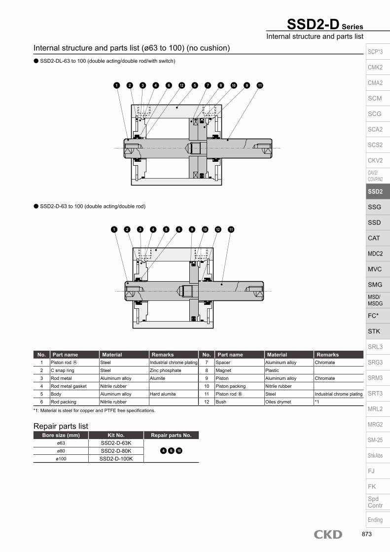
No. Part name Material Remarks No. Part name Material Remarks1 Piston rod A Steel Industrial chrome plating 7 Spacer Aluminum alloy Chromate
2 C snap ring Steel Zinc phosphate 8 Magnet Plastic
3 Rod metal Aluminum alloy Alumite 9 Piston Aluminum alloy Chromate
4 Rod metal gasket Nitrile rubber 10 Piston packing Nitrile rubber
5 Body Aluminum alloy Hard alumite 11 Piston rod B Steel Industrial chrome plating
6 Rod packing Nitrile rubber 12 Bush Oiles drymet *1
Bore size (mm) Kit No. Repair parts No.ø63 SSD2-D-63K
4 6 10ø80 SSD2-D-80Kø100 SSD2-D-100K
Repair parts list
*1: Material is steel for copper and PTFE free specifications.
SSD2-D-63 to 100 (double acting/double rod)
SSD2-D SeriesInternal structure and parts list
Internal structure and parts list (ø63 to 100) (no cushion) SSD2-DL-63 to 100 (double acting/double rod/with switch)
1 2 3 4 6 7 8 91012 115
2 3 4 5 6 9 10 121 11
SCP*3
CMK2
CMA2
SCM
SCG
SCA2
SCS2
CKV2
CAV2/COVP/N2
SSD2
SSG
SSD
CAT
MDC2
MVC
SMG
MSD/MSDG
FC*
STK
SRL3
SRG3
SRM3
SRT3
MRL2
MRG2
SM‑25
ShkAbs
FJ
FK
SpdContr
Ending
873

SSD2-D Series
Internal structure and parts list (ø12 to 50) (with rubber cushion) SSD2-DL-12D to 50D (double acting/double rod/with switch)
SSD2-D-12D to 50D (double acting/double rod)
No. Part name Material Remarks No. Part name Material Remarks
1 Piston rod A ø12 to ø25: Stainless steel ø32 to ø50: Steel
ø16 to ø50: Industrial chrome plating
8 Magnet Plastic
9 Piston Aluminum alloy Chromate2 C snap ring Steel Zinc phosphate
3 Rod metal Special aluminum Alumite 10 Piston packing Nitrile rubber
4 Rod metal gasket Nitrile rubber11 Piston rod B ø12 to ø25: Stainless steel
ø32 to ø50: Steelø16 to ø50: Industrial chrome plating5 Body Aluminum alloy Hard alumite
6 Rod packing Nitrile rubber 12 Cushion rubber Urethane rubber
7 Spacer ø12, ø20, ø32, ø40: Aluminum alloy ø16, ø25, ø50: Special resin
ø12, 20, 32, 40: Chromate
Bore size (mm) Kit No. Repair parts No.ø12 SSD2-D-12DK
4 6 10 12
ø16 SSD2-D-16DKø20 SSD2-D-20DKø25 SSD2-D-25DKø32 SSD2-D-32DKø40 SSD2-D-40DKø50 SSD2-D-50DK
Repair parts list
1 2 3 4 6 5 129 1110
1 2 3 4 6 5 7 11128 10 9
SCP*3
CMK2
CMA2
SCM
SCG
SCA2
SCS2
CKV2
CAV2/COVP/N2
SSD2
SSG
SSD
CAT
MDC2
MVC
SMG
MSD/MSDG
FC*
STK
SRL3
SRG3
SRM3
SRT3
MRL2
MRG2
SM‑25
ShkAbs
FJ
FK
SpdContr
Ending
874

SSD2-D-63D to 100D (double acting/double rod)
SSD2-D SeriesInternal structure and parts list
Internal structure and parts list (ø63 to 100) (with rubber cushion) SSD2-DL-63D to 100D (double acting/double rod/with switch)
No. Part name Material Remarks No. Part name Material Remarks1 Piston rod A Steel Industrial chrome plating 8 Magnet Plastic
2 C snap ring Steel Zinc phosphate 9 Piston Aluminum alloy Chromate
3 Rod metal Aluminum alloy Alumite 10 Piston packing Nitrile rubber
4 Rod metal gasket Nitrile rubber 11 Piston rod B Steel Industrial chrome plating
5 Body Aluminum alloy Hard alumite 12 Bush Oiles drymet *1
6 Rod packing Nitrile rubber 13 Cushion rubber Urethane rubber
7 Spacer Aluminum alloy Chromate
*1: Material is steel for copper and PTFE free specifications.
Bore size (mm) Kit No. Repair parts No.ø63 SSD2-D-63DK
4 6 10 13ø80 SSD2-D-80DKø100 SSD2-D-100DK
Repair parts list
1 2 3 4 6 5 9 11131012
1 2 3 5 7 139 1164 12 8 10
SCP*3
CMK2
CMA2
SCM
SCG
SCA2
SCS2
CKV2
CAV2/COVP/N2
SSD2
SSG
SSD
CAT
MDC2
MVC
SMG
MSD/MSDG
FC*
STK
SRL3
SRG3
SRM3
SRT3
MRL2
MRG2
SM‑25
ShkAbs
FJ
FK
SpdContr
Ending
875

SSD2-D Series
Dimensions SSD2-DL-12 to 25 (with switch) Rod end male thread
ø12/ø16
ø20/ø25
Codea’ c’ H kk’ M MM T wf
Bore size (mm)ø12 10.5 9 8 M5 5 6 3.2 3.5ø16 12 10 10 M6 6 8 3.6 3.5ø20 14 12 13 M8 8 10 5 4.5ø25 17.5 15 17 M10×1.25 10 12 6 5
Dimensions of rod end male thread part
*1 : Only F switch is available for the ø20 or ø25 piping port surface.*2 : HD and RD dimensions for 5 mm stroke length differ from these dimensions according to the setting.*3 : Refer to page 1044 for HD, RD and protruding dimensions of the 2-color display, off-delay, AC magnetic field proof, T1* and T8* switches.*4 : Dimensions in ( ) of FA are for the radial lead wire.*5 : For dimensions of individual accessories, refer to pages 1046 to 1049.*6 : The RD side can be identified with a mark on the port surface of the body.
Code Common dimensions with switchBore size (mm) A B C D EE F FA *5 FB I J K KA KK M MM N WF
ø12 34 27 5.5 5.5 M5 25 13(16.5) 4.5 3.5 6.5 spot face depth 3.5 32 M4 depth 7 M3 depth 6 5 6 15.5 3.5ø16 34 27 5.5 5.5 M5 29 15(18.5) 4.5 3.5 6.5 spot face depth 3.5 38 M4 depth 7 M4 depth 8 6 8 20 3.5ø20 45 36 8 8 M5 36 18.5(22) 12.5 5.5 9 spot face depth 5.5 47 M6 depth 11 M5 depth 7 8 10 25.5 4.5ø25 49 39 11 11 M5 40 20.5(24) 13.5 5.5 9 spot face depth 5.5 51 M6 depth 11 M6 depth 12 10 12 28 5
Switch dimensions
Reed T0H/T0V,T5H/T5V *6
Proximity T2H/T2V,T3H/T3V *6
Proximity T2WH/T2WV,T3WH/T3WV *6
Proximity F2H/F2V, F3H/F3V,F2YH/F2YV, F3YH/F3YV Proximity F2S/F3S
Bore size (mm) HD RD HD RD HD RD HD RD HD RDø12 5.5 3 5.5 3 7.5 4.5ø16 5 2 5 2 6.5 3.5ø20 10 7.5 10 7.5 11.5 9.5 14 12 13 11ø25 11.5 9.5 11.5 9.5 11.5 11 15 13 14 12
Note: The positions for the left and right widths across flats are unspecified.
a’c’
T
wf
kk’Width across flats M
Width across flats H
F8-J(Mounting hole) N
øK
F N
FBM
FA
FB
FA
øMM
WF
KK
C D
2-EE
8-KAøI
A + (2 × stroke length)B + stroke length
*5
*5
KK
WF + stroke length
HD
F8-J
(Mounting hole)N
øK
F N
M
FA
FB
øMM
WF
KK
C D2-EE
8-KAøIB + stroke length
*5
KK
WF + stroke length
HD
A + (2 × stroke length)
RD
øMM
RD
SCP*3
CMK2
CMA2
SCM
SCG
SCA2
SCS2
CKV2
CAV2/COVP/N2
SSD2
SSG
SSD
CAT
MDC2
MVC
SMG
MSD/MSDG
FC*
STK
SRL3
SRG3
SRM3
SRT3
MRL2
MRG2
SM‑25
ShkAbs
FJ
FK
SpdContr
Ending
876

Dimensions with mounting bracket Axial foot (LB) with switch SSD2-DL-12 to 25 -LB
SSD2-D SeriesDouble acting/double rod
Code Female thread Male threadBore size
(mm) WF LF A B LX a’ wf LF A B LX
ø12 13.5 19.5 54 27 15 10.5 13.5 19.5 75 27 15ø16 13.5 19.5 54 27 15 12 13.5 19.5 78 27 15ø20 14.5 20.5 65 36 24 14 14.5 20.5 93 36 24ø25 15 22.5 69 39 24 17.5 15 22.5 104 39 24
Code Common dimensionsBore size
(mm) AB AG AH AK AT AU G N TR TS M
ø12 5 29.5 17 12.5 2 8 M4×10 15.5 34 44 4.8ø16 5 33.5 19 13 2 8 M4×10 20 38 48 4.8ø20 7 42 24 15 3.2 9.2 M6×16 25.5 48 62 7.2ø25 7 46 26 16.5 3.2 10.7 M6×16 28 52 66 7.2
Rod side flange (FA) with switch SSD2-DL-12 to 25 -FA
Rod end male thread
Code Common dimensions Female thread Male threadBore size
(mm) FD FH FL FM FT N G WF1 WF2 A B a’ wf1 wf2 A B
ø12 4.5 25 45 55 5.5 15.5 M4×12 13.5 3.5 44 27 11 13.5 3.5 65 27ø16 4.5 30 45 55 5.5 20 M4×12 13.5 3.5 44 27 12 13.5 3.5 68 27ø20 6.6 39 48 60 8 25.5 M6×16 14.5 4.5 55 36 14 14.5 4.5 83 36ø25 6.6 42 52 64 8 28 M6×16 15 5 59 39 18 15 5 94 39
Rod end male thread
N
AG N
TRTS
AT
AH
4-øAB
WF
A + (2 × stroke length)
B + stroke length
M
AU
LX + stroke length
A + (2 × stroke length)
B + stroke lengtha’ wf
LF
LF
AK
LF + stroke length
wf + stroke length a’
LF + stroke length
WF + stroke length
Low head hexagon socket bolt 8-G
FM
NFH
N
2-FD
Mounting bolt 4-GHexagon socket button head bolt
FL
A + (2 × stroke length)
B + stroke length
FTB + stroke lengtha’ wf1
WF1 WF2 + stroke lengthwf2 + stroke length a’
A + (2 × stroke length)
SCP*3
CMK2
CMA2
SCM
SCG
SCA2
SCS2
CKV2
CAV2/COVP/N2
SSD2
SSG
SSD
CAT
MDC2
MVC
SMG
MSD/MSDG
FC*
STK
SRL3
SRG3
SRM3
SRT3
MRL2
MRG2
SM‑25
ShkAbs
FJ
FK
SpdContr
Ending
877

Dimensions SSD2-D-12 to 25 (without switch) Rod end male thread
ø12/ø16
Note: The positions for the left and right widths across flats are unspecified.
*1: For dimensions of individual accessories, refer to pages 1046 to 1049.
Codea’ c’ H kk’ M MM T wf
Bore size (mm)ø12 10.5 9 8 M5 5 6 3.2 3.5
ø16 12 10 10 M6 6 8 3.6 3.5
ø20 14 12 13 M8 8 10 5 4.5
ø25 17.5 15 17 M10×1.25 10 12 6 5
Dimensions of rod end male thread part
Code Dimensions without switch and common dimensionsBore size (mm) A B C D EE F I J K KA KK M MM N WF
ø12 29 22 5.5 5.5 M5 25 3.5 6.5 spot face depth 3.5 32 M4 depth 7 M3 depth 6 5 6 15.5 3.5
ø16 29 22 5.5 5.5 M5 29 3.5 6.5 spot face depth 3.5 38 M4 depth 7 M4 depth 8 6 8 20 3.5
ø20 35 26 8 8 M5 36 5.5 9 spot face depth 5.5 47 M6 depth 11 M5 depth 7 8 10 25.5 4.5
ø25 39 29 11 11 M5 40 5.5 9 spot face depth 5.5 51 M6 depth 11 M6 depth 12 10 12 28 5
ø20/ø25
SSD2-D Series
a’c’
T
wf
kk’Width across flats M
Width across flats H
øMM
F8-J(Mounting hole) N
øK
F N
M
øMM
WF
KK
C D2-EE
8-KAøI
A + (2 × stroke length)B + stroke length
KK
WF + stroke length
F8-J
(Mounting hole) N
øK
F N
M
øMM
WF
KK
C D2-EE
8-KAøI
B + stroke length
KK
WF + stroke lengthA + (2 × stroke length)
SCP*3
CMK2
CMA2
SCM
SCG
SCA2
SCS2
CKV2
CAV2/COVP/N2
SSD2
SSG
SSD
CAT
MDC2
MVC
SMG
MSD/MSDG
FC*
STK
SRL3
SRG3
SRM3
SRT3
MRL2
MRG2
SM‑25
ShkAbs
FJ
FK
SpdContr
Ending
878

Dimensions with mounting bracket Axial foot (LB) without switch SSD2-D-12 to 25 -LB
SSD2-D SeriesDouble acting/double rod
Rod end male thread
Rod side flange (FA) without switch SSD2-D-12 to 25 -FA
Rod end male thread
Code Common dimensionsBore size
(mm) AB AG AH AK AT AU G N TR TS M
ø12 5 29.5 17 12.5 2 8 M4×10 15.5 34 44 4.8ø16 5 33.5 19 13 2 8 M4×10 20 38 48 4.8ø20 7 42 24 15 3.2 9.2 M6×16 25.5 48 62 7.2ø25 7 46 26 16.5 3.2 10.7 M6×16 28 52 66 7.2
Code Female thread Male threadBore size
(mm) WF LF A B LX a’ wf LF A B LX
ø12 13.5 19.5 49 22 10 10.5 13.5 19.5 70 22 10ø16 13.5 19.5 49 22 10 12 13.5 19.5 73 22 10ø20 14.5 20.5 55 26 14 14 14.5 20.5 83 26 14ø25 15 22.5 59 29 14 17.5 15 22.5 94 29 14
Code Common dimensions Female thread Male threadBore size
(mm) FD FH FL FM FT N G WF1 WF2 A B a’ wf1 wf2 A B
ø12 4.5 25 45 55 5.5 15.5 M4×12 13.5 3.5 39 22 11 13.5 3.5 60 22ø16 4.5 30 45 55 5.5 20 M4×12 13.5 3.5 39 22 12 13.5 3.5 63 22ø20 6.6 39 48 60 8 25.5 M6×16 14.5 4.5 45 26 14 14.5 4.5 73 26ø25 6.6 42 52 64 8 28 M6×16 15 5 49 29 18 15 5 84 29
N
AG N
TRTS
AT
AH
4-øAB
WF
A + (2 × stroke length)
B + stroke length
M
AU
LX + stroke length
A + (2 × stroke length)
B + stroke lengtha’ wf
LF
LF
AK
LF + stroke length
wf + stroke length a’
LF + stroke length
WF + stroke length
Low head hexagon socket bolt 8-G
FM
NFH
N
2-FD
Mounting bolt 4-GHexagon socket button head bolt
FL
A + (2 × stroke length)
B + stroke length
FTB + stroke lengtha’ wf1
WF1 WF2 + stroke length
wf2 + stroke length a’
A + (2 × stroke length)
SCP*3
CMK2
CMA2
SCM
SCG
SCA2
SCS2
CKV2
CAV2/COVP/N2
SSD2
SSG
SSD
CAT
MDC2
MVC
SMG
MSD/MSDG
FC*
STK
SRL3
SRG3
SRM3
SRT3
MRL2
MRG2
SM‑25
ShkAbs
FJ
FK
SpdContr
Ending
879
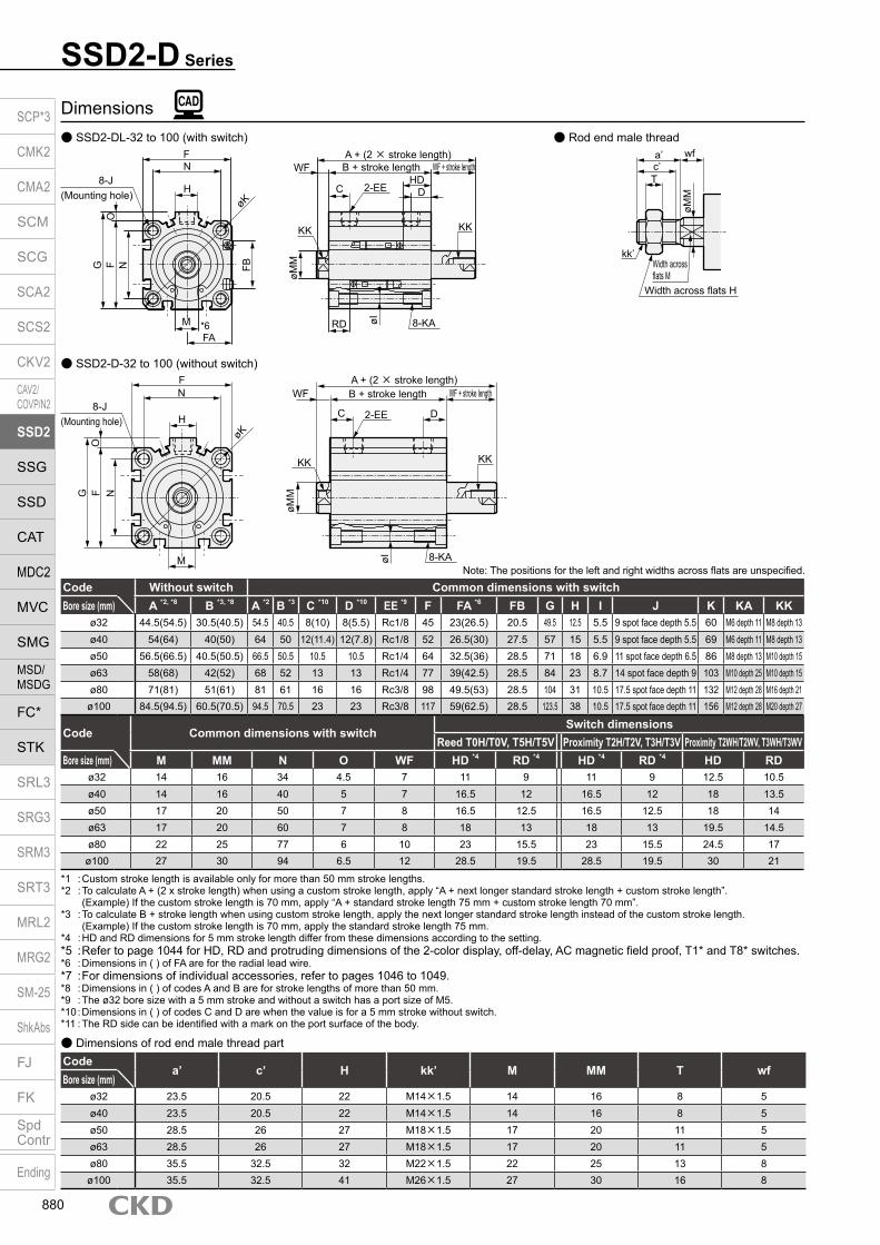
SSD2-D Series
Dimensions SSD2-DL-32 to 100 (with switch) Rod end male thread
SSD2-D-32 to 100 (without switch)
Codea’ c’ H kk’ M MM T wf
Bore size (mm)ø32 23.5 20.5 22 M14×1.5 14 16 8 5ø40 23.5 20.5 22 M14×1.5 14 16 8 5ø50 28.5 26 27 M18×1.5 17 20 11 5ø63 28.5 26 27 M18×1.5 17 20 11 5ø80 35.5 32.5 32 M22×1.5 22 25 13 8
ø100 35.5 32.5 41 M26×1.5 27 30 16 8
Dimensions of rod end male thread part
Code Common dimensions with switchSwitch dimensions
Reed T0H/T0V, T5H/T5V Proximity T2H/T2V, T3H/T3V Proximity T2WH/T2WV, T3WH/T3WVBore size (mm) M MM N O WF HD *4 RD *4 HD *4 RD *4 HD RD
ø32 14 16 34 4.5 7 11 9 11 9 12.5 10.5ø40 14 16 40 5 7 16.5 12 16.5 12 18 13.5ø50 17 20 50 7 8 16.5 12.5 16.5 12.5 18 14ø63 17 20 60 7 8 18 13 18 13 19.5 14.5ø80 22 25 77 6 10 23 15.5 23 15.5 24.5 17ø100 27 30 94 6.5 12 28.5 19.5 28.5 19.5 30 21
*1 : Custom stroke length is available only for more than 50 mm stroke lengths.*2 : To calculate A + (2 x stroke length) when using a custom stroke length, apply “A + next longer standard stroke length + custom stroke length”.
(Example) If the custom stroke length is 70 mm, apply “A + standard stroke length 75 mm + custom stroke length 70 mm”.*3 : To calculate B + stroke length when using custom stroke length, apply the next longer standard stroke length instead of the custom stroke length. (Example) If the custom stroke length is 70 mm, apply the standard stroke length 75 mm.*4 : HD and RD dimensions for 5 mm stroke length differ from these dimensions according to the setting.*5 : Refer to page 1044 for HD, RD and protruding dimensions of the 2-color display, off-delay, AC magnetic field proof, T1* and T8* switches.*6 : Dimensions in ( ) of FA are for the radial lead wire.*7 : For dimensions of individual accessories, refer to pages 1046 to 1049.*8 : Dimensions in ( ) of codes A and B are for stroke lengths of more than 50 mm.*9 : The ø32 bore size with a 5 mm stroke and without a switch has a port size of M5.*10 : Dimensions in ( ) of codes C and D are when the value is for a 5 mm stroke without switch.*11 : The RD side can be identified with a mark on the port surface of the body.
Code Without switch Common dimensions with switchBore size (mm) A *2, *8 B *3, *8 A *2 B *3 C *10 D *10 EE *9 F FA *6 FB G H I J K KA KK
ø32 44.5(54.5) 30.5(40.5) 54.5 40.5 8(10) 8(5.5) Rc1/8 45 23(26.5) 20.5 49.5 12.5 5.5 9 spot face depth 5.5 60 M6 depth 11 M8 depth 13ø40 54(64) 40(50) 64 50 12(11.4) 12(7.8) Rc1/8 52 26.5(30) 27.5 57 15 5.5 9 spot face depth 5.5 69 M6 depth 11 M8 depth 13ø50 56.5(66.5) 40.5(50.5) 66.5 50.5 10.5 10.5 Rc1/4 64 32.5(36) 28.5 71 18 6.9 11 spot face depth 6.5 86 M8 depth 13 M10 depth 15ø63 58(68) 42(52) 68 52 13 13 Rc1/4 77 39(42.5) 28.5 84 23 8.7 14 spot face depth 9 103 M10 depth 25 M10 depth 15ø80 71(81) 51(61) 81 61 16 16 Rc3/8 98 49.5(53) 28.5 104 31 10.5 17.5 spot face depth 11 132 M12 depth 28 M16 depth 21
ø100 84.5(94.5) 60.5(70.5) 94.5 70.5 23 23 Rc3/8 117 59(62.5) 28.5 123.5 38 10.5 17.5 spot face depth 11 156 M12 depth 28 M20 depth 27
Note: The positions for the left and right widths across flats are unspecified.
a’c’T
wf
kk’Width across flats M
Width across flats H
øMM
F
8-J(Mounting hole)
N
øK
F N
M
FB
øMM
WF
KK
C D2-EE
8-KAøI
A + (2 × stroke length)B + stroke length
FA*6
KK
WF + stroke lengthHD
H
OG
RD
F
8-J(Mounting hole)
N
øK
F N
M
øMM
WF
KK
C D2-EE
8-KAøIA + (2 × stroke length)B + stroke length
KK
WF + stroke length
H
OG
SCP*3
CMK2
CMA2
SCM
SCG
SCA2
SCS2
CKV2
CAV2/COVP/N2
SSD2
SSG
SSD
CAT
MDC2
MVC
SMG
MSD/MSDG
FC*
STK
SRL3
SRG3
SRM3
SRT3
MRL2
MRG2
SM‑25
ShkAbs
FJ
FK
SpdContr
Ending
880

Dimensions with mounting bracket Axial foot (LB) SSD2-D(L)-32 to 100 -LB
SSD2-D SeriesDouble acting/double rod
Rod side flange (FA) SSD2-D(L)-32 to 100 -FA
Rod end male thread
Code Common dimensionsBore size
(mm) AB AD AE AG AH AK AT AU G N TR TS M
ø32 7 18.5 13 57 30 17 3.2 11.2 M6×16 34 57 71 7.2ø40 7 18 13 64 33 18.2 3.2 11.2 M6×16 40 64 78 7.2ø50 9 22 14 78 39 22.7 3.2 14.7 M8×20 50 79 95 8.2ø63 11 26 16 91.5 46 25.2 3.2 16.2 M10×25 60 95 113 9.2ø80 13 31.5 20.5 114 59 30.5 4.5 19.5 M12×40 77 118 140 11.5ø100 13 35 24 136 71 35.5 6 23 M12×40 94 137 162 13
Code Female thread Male threadBore size
(mm) WF LF Without switch With switch a’ wf LF Without switch With switchA B LX A B LX A B LX A B LX
ø32 17 25 64.5(74.5) 30.5(40.5) 14.5(24.5) 74.5 40.5 24.5 23.5 15 23 107.5(117.5) 30.5(40.5) 14.5(24.5) 117.5 40.5 24.5ø40 17 25 74(84) 40(50) 24(34) 84 50 34 23.5 15 23 117(127) 40(50) 24(34) 127 50 34ø50 18 29.5 76.5(86.5) 40.5(50.5) 17.5(27.5) 86.5 50.5 27.5 28.5 15 26.5 127.5(137.59) 40.5(50.5) 17.5(27.5) 137.5 50.5 27.5ø63 18 31 78(88) 42(52) 16(26) 88 52 26 28.5 15 28 129(139) 42(52) 16(26) 139 52 26ø80 20 35 91(101) 51(61) 21(31) 101 61 31 35.5 18 33 158(168) 51(61) 21(31) 168 61 31
ø100 22 39 104.5(114.5) 60.5(70.5) 26.5(36.5) 115 70.5 36.5 35.5 18 35 167.5(177.5) 60.5(70.5) 26.5(36.5) 177.5 70.5 36.5* Dimensions in ( ) are for stroke lengths of more than 50 mm.Note: ø80: LB cannot be selected when B + stroke length is 72 or less.
Code Common dimensions Female thread Male threadBore size
(mm) FC FD FH FL FM FT N G WF1 WF2 Without switch With switch a’ wf1 wf2 Without switch With switchA B A B A B A B
ø32 34 5.5 48 56 65 8 34 M6×16 17 7 54.5(64.5) 30.5(40.5) 64.5 40.5 24 15 5 97.5(107.5) 30.5(40.5) 107.5 40.5ø40 40 5.5 54 62 72 8 40 M6×16 17 7 64(74) 40(50) 74 50 24 15 5 107(117) 40(50) 117 50ø50 50 6.6 67 76 89 9 50 M8×20 18 8 66.5(76.5) 40.5(50.5) 76.5 50.5 29 15 5 117.5(127.5) 40.5(50.5) 127.5 50.5ø63 60 9 80 92 108 9 60 M10×25 18 8 68(78) 42(52) 78 52 29 15 5 119(129) 42(52) 129 52ø80 77 11 99 116 134 11 77 M12×40 20 10 81(91) 51(61) 91 61 36 18 8 148(158) 51(61) 158 61
ø100 94 11 117 136 154 11 94 M12×40 22 12 94.5(104.5) 60.5(70.5) 104.5 70.5 36 18 8 157.5(167.5) 60.5(70.5) 167.5 70.5* Dimensions in ( ) are for stroke lengths of more than 50 mm.
NTRTS
4-øAB
AD
AE A
T AH
LF
a’ wf
LX + stroke length
Low head hexagon socket bolt 4-G
LF
WF
AU
AK
M
AG
A + (2 × stroke length)
B + stroke length WF + stroke length
LF + stroke length
A + (2 × stroke length)B + stroke length wf + stroke length a’
M
LX + stroke length LF + stroke length
AUAK
Rod end male thread
FH FC
FM
NFL
4-FD
Mounting bolt 4-Gø32 to ø63: Hexagon socket button head boltø80/ø100: Special bolt
A + (2 × stroke length)
B + stroke lengthFT
B + stroke lengtha’ wf1WF1 WF2 + stroke length wf2 + stroke length a’
A + (2 × stroke length)
SCP*3
CMK2
CMA2
SCM
SCG
SCA2
SCS2
CKV2
CAV2/COVP/N2
SSD2
SSG
SSD
CAT
MDC2
MVC
SMG
MSD/MSDG
FC*
STK
SRL3
SRG3
SRM3
SRT3
MRL2
MRG2
SM‑25
ShkAbs
FJ
FK
SpdContr
Ending
881

Compact cylinder double acting/double rod (large bore size)
SSD2-D Series Bore size: ø125/ø140/ø160/ø180/ø200
JIS symbol
SpecificationsItem SSD2-D
SSD2-DL (with switch)Bore size mm ø125 ø140 ø160 ø180 ø200Actuation Double acting/double rodWorking fluid Compressed airMax. working pressure MPa 1.0 (≈150 psi, 10 bar) 0.7 (≈100 psi, 7 bar)Min. working pressure MPa 0.05 (≈7.3 psi, 0.5 bar)Proof pressure MPa 1.6 (≈230 psi, 16 bar) 1.05 (≈150 psi, 10.5 bar)Ambient temperature °C -10 (14°F) to 60 (140°F) (no freezing)Port size Rc3/8 Rc1/2
Stroke tolerance mm+2.0
0Working piston speed mm/s 50 to 300 20 to 300Cushion With rubber cushion (standard)Lubrication Not required (use turbine oil ISO VG32 if necessary for lubrication)Allowable absorbed energy J 6.52 6.52 7.78 12.4
Stroke lengthBore size (mm) Standard stroke length (mm) Max. stroke length (mm) Min. stroke length (mm)
ø12510, 20, 30, 40, 5075, 100, 125, 150175, 200, 250, 300
300 10ø140ø160ø180ø200
*1: Total length dimension with custom stroke length is handled as custom stroke dedicated length.*2: When using the type with switch, refer to the table below.
Number of installed switches and min. stroke length (mm)Switch quantity 1 2 3 4 5Switch model No.
T* T* T* T* T*Bore size (mm)
ø125 10 10 40 55 70ø140 10 10 40 55 70ø160 10 10 40 55 70ø180 10 10 40 55 70ø200 10 10 40 55 70
SCP*3
CMK2
CMA2
SCM
SCG
SCA2
SCS2
CKV2
CAV2/COVP/N2
SSD2
SSG
SSD
CAT
MDC2
MVC
SMG
MSD/MSDG
FC*
STK
SRL3
SRG3
SRM3
SRT3
MRL2
MRG2
SM‑25
ShkAbs
FJ
FK
SpdContr
Ending
882

Switch specifications 1-color/2-color display/for AC magnetic field proof
SSD2-D (Large bore size) SeriesSpecifications
Stroke length (mm) 125 150 175 200 250 300Bore size (mm) No switch With switch No switch With switch No switch With switch No switch With switch No switch With switch No switch With switch
ø125 8.55 8.65 9.40 9.50 10.25 10.35 11.10 11.20 12.80 12.90 14.50 14.60ø140 11.02 11.13 11.87 11.98 12.72 12.83 13.57 13.68 15.27 15.38 16.97 17.08ø160 14.61 14.73 15.81 15.93 17.01 17.13 18.21 18.33 20.61 20.73 23.01 23.13ø180 18.85 19.00 20.10 20.25 21.35 21.50 22.59 22.74 25.09 25.24 27.58 27.73ø200 22.53 22.71 23.93 24.11 25.32 25.50 26.72 26.90 29.52 29.70 32.32 32.50
Stroke length (mm) 10 20 30 40 50 75 100Bore size (mm) No switch With switch No switch With switch No switch With switch No switch With switch No switch With switch No switch With switch No switch With switch
ø125 4.64 4.74 4.98 5.08 5.32 5.42 5.66 5.76 6.00 6.10 6.85 6.95 7.70 7.80ø140 6.62 6.73 7.00 7.11 7.38 7.49 7.77 7.88 8.15 8.26 9.00 9.11 10.07 10.18ø160 9.10 9.22 9.58 9.70 10.06 10.18 10.54 10.66 11.02 11.14 12.22 12.34 13.41 13.53ø180 13.12 13.27 13.62 13.77 14.12 14.27 14.62 14.77 15.12 15.27 16.36 16.51 17.61 17.76ø200 16.09 16.27 16.65 16.83 17.21 17.39 17.77 17.95 18.33 18.51 19.73 19.91 21.13 21.31
Cylinder weight table (the weight of the switches is when there are 2 cylinder switches.)
ItemProximity 2-wire Proximity 2-wire Proximity 3-wire Reed 2-wire Proximity 2-wire
T1H/T1V
T2H/T2V/T2JH/T2JV
T2YH/T2YV
T2WH/T2WV
T3H/T3V
T3PH/T3PV
T3YH/T3YV
T3WH/T3WV
T0H/T0V T5H/T5V T8H/T8VT2YD(*4)T2YDT
ApplicationsFor programmable
controller, relay, compact solenoid valve
Dedicated for programmable controller
For programmable controller, relay
For programmable controller, relay
For programmable controller, relay, IC circuit (no indicator
lamp), serial connection
For programmable controller, relay
For programmable
controllerOutput method - NPN output PNP output NPN output NPN output -Pwr. supp. V. - 10 to 28 VDC -Load voltage 85 to 265 VAC 10 to 30 VDC 24 VDC ±10% 30 VDC or less 12/24 VDC 100/110 VAC 5/12/24 VDC 100/110 VAC 12/24 VDC 110 VAC 220 VAC 24 VDC ±10%Load current 5 to 100 mA 5 to 20 mA (*3) 100 mA or less 50 mA or less 5 to 50 mA 7 to 20 mA 50 mA or less 20 mA or less 5 to 50 mA 7 to 20 mA 7 to 10 mA 5 to 20 mA
Indicator lamp
LED(Lit when
ON)
LED(Lit when
ON)
Red/green LED
(Lit when ON)
Red/green LED
(Lit when ON)
LED(Lit when
ON)
Yellow LED
(Lit when ON)
Red/green LED
(Lit when ON)
Red/green LED
(Lit when ON)
LED(Lit when ON)
Without indicator lamp
LED(Lit when ON)
Red/green LED
(Lit when ON)Leakage current
≤ 1 mA at 100 VAC, ≤ 2 mA at 200 VAC
1 mA or less 10 μA or less 0 mA1 mA or
less
Weight g1 m:333 m:875 m:142
1 m:183 m:495 m:80
1 m:333 m:875 m:142
1 m:183 m:495 m:80
1 m:183 m:495 m:80
1 m:333 m:875 m:142
1 m:183 m:495 m:80
1 m:18 3 m:49 5 m:801 m:333 m:875 m:142
1 m:613 m:1665 m:272
*1 : Refer to Ending Page 1 for detailed switch specifications and dimensions. *2 : Switches other than the above models, such as switches with connectors, are also available. Refer to Ending Page 1. *3 : The max. load current is 20 mA at 25°C. The current is lower than 20 mA if the operating ambient temperature around the switch is higher than 25˚C.
(5 to 10 mA at 60°C) *4 : Switch for AC magnetic field (T2YD/T2YDT) cannot be used in DC magnetic field. *5 : The F type switch uses a bend-resistant lead wire.
Bore size (mm)
Operating direction
Working pressure MPa0.1 0.15 0.2 0.3 0.4 0.5 0.6 0.7 0.8 0.9 1.0
ø125 Push/Pull 1.13×10³ 1.70×10³ 2.26×10³ 3.39×10³ 4.52×10³ 5.65×10³ 6.79×10³ 7.92×10³ 9.05×10³ 1.02×10⁴ 1.13×10⁴
ø140 Push/Pull 1.44×10³ 2.16×10³ 2.89×10³ 4.33×10³ 5.77×10³ 7.22×10³ 8.66×10³ 1.01×10⁴ 1.15×10⁴ 1.30×10⁴ 1.44×10⁴
ø160 Push/Pull 1.88×10³ 2.83×10³ 3.77×10³ 5.65×10³ 7.54×10³ 9.42×10³ 1.13×10⁴ 1.32×10⁴ - - -ø180 Push/Pull 2.39×10³ 3.58×10³ 4.77×10³ 7.16×10³ 9.54×10³ 1.19×10⁴ 1.43×10⁴ 1.67×10⁴ - - -ø200 Push/Pull 3.02×10³ 4.52×10³ 6.03×10³ 9.05×10³ 1.21×10⁴ 1.51×10⁴ 1.81×10⁴ 2.11×10⁴ - - -
Theoretical thrust table (Unit: N)
(Unit: kg)
SCP*3
CMK2
CMA2
SCM
SCG
SCA2
SCS2
CKV2
CAV2/COVP/N2
SSD2
SSG
SSD
CAT
MDC2
MVC
SMG
MSD/MSDG
FC*
STK
SRL3
SRG3
SRM3
SRT3
MRL2
MRG2
SM‑25
ShkAbs
FJ
FK
SpdContr
Ending
883

SSD2-D (Large bore size) Series
How to order switch
Switch model No. (Item D above)
How to orderWithout switch (without magnet for switch)
With switch (built-in magnet for switch)
N
F Option
50
Switch quantityE
Switch model No.*1
D
C Stroke length
Port threadB
Bore sizeA
R N50
Code DescriptionBore size (mm)125 ø125140 ø140160 ø160180 ø180200 ø200
Port threadBlank Rc thread
NN NPT thread (ø125 to ø160) (made-to-order product)GN G thread (ø125 to ø160) (made-to-order product)
Stroke length (mm)
Refer to the stroke length table on the following page.
* Lead wire lengthBlank 1 m (standard)
3 3 m (option)5 5 m (option)
Switch quantityR 1 on rod sideH 1 on head sideD 2
OptionBlank Rod end female thread
N Rod end male threadP4
Specifications for rechargeable battery (made to order)P40
Switch model No.Lead wire Lead wire
Cont
act
VoltageDisplay
Lead Straight L-shaped AC DC Line
T0H* T0V*
Ree
d 1-color display2-wireT5H* T5V* Without indicator lamp
T8H* T8V* 1-color displayT1H* T1V*
Pro
xim
ity
1-color display2-wire
T2H* T2V*
T3H* T3V* 3-wire
T3PH* T3PV* 1-color displayT2WH* T2WV*
2-color display2-wire
T2YH* T2YV*
T3WH* T3WV* 3-wire
T3YH* T3YV*
T2JH* T2JV* 1-color display off-delay 2-wireT2YD* - 2-color display
AC magnetic field 2-wireT2YDT* -
A
B
C
F
D
E
Precautions for model No. selection*1: Switches are shipped with the product. Contact CKD
if assembling before shipment is necessary.
[Example of model No.]SSD2-DL-125-50-T0H-R-NModel: Compact cylinder double acting/double rodA Bore size : 125 mmB Port thread : Rc threadC Stroke length : 50 mmD Switch model No. : Reed T0H switch · Lead wire length 1 mE Switch quantity : 1 on rod sideF Option : Rod end male thread
SSD2-D 125
SSD2-DL 125 T0H
SW T0H
SCP*3
CMK2
CMA2
SCM
SCG
SCA2
SCS2
CKV2
CAV2/COVP/N2
SSD2
SSG
SSD
CAT
MDC2
MVC
SMG
MSD/MSDG
FC*
STK
SRL3
SRG3
SRM3
SRT3
MRL2
MRG2
SM‑25
ShkAbs
FJ
FK
SpdContr
Ending
884

SSD2-D (Large bore size) SeriesHow to order
*1 : Refer to page 882 for the number of installed switches and the min. stroke length.*2 : Total length dimension with custom stroke length is handled as custom stroke dedicated length.
Stroke length (mm)Applicable bore size
ø125 ø140 ø160 ø180 ø200
Sta
ndar
d st
roke
leng
th
10 20 30 40 50 75
100 125 150 175 200 250 300
Min. stroke length (mm) *1 10Max. stroke length (mm) 300Custom stroke length *2 In 1 mm increments
[Stroke length table] SCP*3
CMK2
CMA2
SCM
SCG
SCA2
SCS2
CKV2
CAV2/COVP/N2
SSD2
SSG
SSD
CAT
MDC2
MVC
SMG
MSD/MSDG
FC*
STK
SRL3
SRG3
SRM3
SRT3
MRL2
MRG2
SM‑25
ShkAbs
FJ
FK
SpdContr
Ending
885
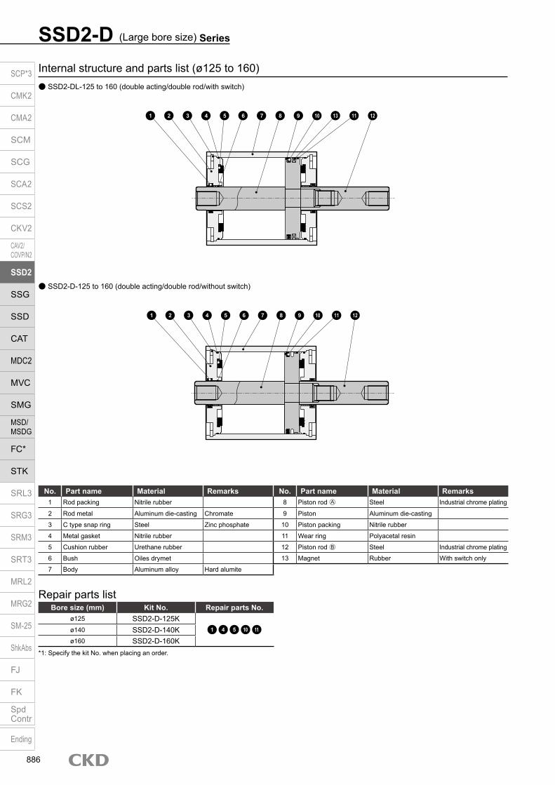
Internal structure and parts list (ø125 to 160) SSD2-DL-125 to 160 (double acting/double rod/with switch)
SSD2-D-125 to 160 (double acting/double rod/without switch)
No. Part name Material Remarks No. Part name Material Remarks1 Rod packing Nitrile rubber 8 Piston rod A Steel Industrial chrome plating
2 Rod metal Aluminum die-casting Chromate 9 Piston Aluminum die-casting
3 C type snap ring Steel Zinc phosphate 10 Piston packing Nitrile rubber
4 Metal gasket Nitrile rubber 11 Wear ring Polyacetal resin
5 Cushion rubber Urethane rubber 12 Piston rod B Steel Industrial chrome plating
6 Bush Oiles drymet 13 Magnet Rubber With switch only
7 Body Aluminum alloy Hard alumite
Repair parts listBore size (mm) Kit No. Repair parts No.
ø125 SSD2-D-125K1 4 5 10 11ø140 SSD2-D-140K
ø160 SSD2-D-160K*1: Specify the kit No. when placing an order.
SSD2-D (Large bore size) Series
1 2 3 4 5 6 7 8 9 10 13 11 12
1 2 3 4 5 6 7 8 9 10 11 12
SCP*3
CMK2
CMA2
SCM
SCG
SCA2
SCS2
CKV2
CAV2/COVP/N2
SSD2
SSG
SSD
CAT
MDC2
MVC
SMG
MSD/MSDG
FC*
STK
SRL3
SRG3
SRM3
SRT3
MRL2
MRG2
SM‑25
ShkAbs
FJ
FK
SpdContr
Ending
886

SSD2-D (Large bore size) SeriesInternal structure and parts list
Internal structure and parts list (ø180, ø200) SSD2-DL-180, 200 (double acting/double rod/with switch)
No. Part name Material Remarks No. Part name Material Remarks1 Rod packing Nitrile rubber 8 Piston Aluminum alloy
2 Rod metal Cast iron Paint 9 Piston packing Nitrile rubber
3 C type snap ring Steel Zinc phosphate 10 Wear ring Polyacetal resin
4 Gasket Nitrile rubber 11 Cover Cast iron Paint
5 Cushion rubber Urethane rubber 12 Magnet Rubber With switch only
6 Bush Oiles drymet 13 Piston rod A Steel Industrial chrome plating
7 Body Aluminum alloy Hard alumite 14 Piston rod B Steel Industrial chrome plating
Repair parts listBore size (mm) Kit No. Repair parts No.
ø180 SSD2-D-180K1 4 5 9 10
ø200 SSD2-D-200K
Parts list
SSD2-D-180, 200 (double acting/double rod/without switch)
1 2 3 4 5 7 6 13 9 12 10 8 11 14
1 2 3 4 5 7 6 913 1110 8 14
SCP*3
CMK2
CMA2
SCM
SCG
SCA2
SCS2
CKV2
CAV2/COVP/N2
SSD2
SSG
SSD
CAT
MDC2
MVC
SMG
MSD/MSDG
FC*
STK
SRL3
SRG3
SRM3
SRT3
MRL2
MRG2
SM‑25
ShkAbs
FJ
FK
SpdContr
Ending
887

Dimensions (ø125 to ø160) SSD2-D(L)-125 to 160 (double acting/single rod) Rod end male thread
*1: Values in ( ) for KK dimensions indicate effective thread length on one side with 10 mm stroke length.*2: Dimensions in ( ) of FA are for the radial lead wire.*3: The RD side can be identified by a mark on the port surface of the body.
Code Common dimensions with switchBore size (mm) A B C D EE F I J K KA KK (*1) L M MM N WF
ø125 115 83 29 29 Rc3/8 142 12.5 20 spot face depth 13 190 M14 depth 25 M22 x 2.5 depth 30 (22.5) 72 30 35 114 16
ø140 115 83 27.5 27.5 Rc3/8 158 12.5 20 spot face depth 13 210 M14 depth 25 M22 x 2.5 depth 30 (22.5) 80 30 35 128 16
ø160 125 91 30 30 Rc3/8 178 14.7 23 spot face depth 15.2 238 M16 depth 28 M24 x 3 depth 33 (24) 90 36 40 144 17
Dimensions of rod end male threadCode
a’ c’ H kk’ M MM T wfBore size (mm)
ø125 45 42 46 M30×1.5 30 35 18 13
ø140 45 42 46 M30×1.5 30 35 18 13
ø160 50 47 55 M36×1.5 36 40 21 14
SSD2-D (Large bore size) Series
Note: The positions for the left and right widths across flats are unspecified.
Code T2WH/V, T3WH/V T8H/VBore size (mm) HD RD FA *2 FB HD RD FA *2 FB
ø125 31.5 36.5 71.5(75) 44.5 24 29 77(80) 48
ø140 33 35 79.5(83) 44.5 25.5 27.5 85(88) 48
ø160 35.5 40.5 89.5(93) 48.5 28 33 95(98) 52
Code T0H/V, T2H/V, T3H/V, T5/V T2YH/V, T3YH/V, T2JH/V T1H/V, T2YDBore size (mm) HD RD FA *2 FB HD RD FA *2 FB HD RD FA *2 FB
ø125 30 35 71.5(75) 44.5 28.5 33.5 77(80) 48 28.5 33.5 82.5(85.5) 48
ø140 31.5 33.5 79.5(83) 44.5 30 32 85(88) 48 30 32 90.5(93.5) 48
ø160 34 39 89.5(93) 48.5 32.5 37.5 95(98) 52 32.5 37.5 100.5(103.5) 52
2-EEF
N
NL
FøK
MFA*2
FB
8-JMounting hole
8-KAøI
øMM
KK
WF
(both ends)
C
HD
Da
A + (2 × stroke length)B + stroke length WF + stroke length
a’c’
T
WF
øMM
kk’
Width across flats H Width across flats MRD
bab
SCP*3
CMK2
CMA2
SCM
SCG
SCA2
SCS2
CKV2
CAV2/COVP/N2
SSD2
SSG
SSD
CAT
MDC2
MVC
SMG
MSD/MSDG
FC*
STK
SRL3
SRG3
SRM3
SRT3
MRL2
MRG2
SM‑25
ShkAbs
FJ
FK
SpdContr
Ending
888

Dimensions (ø180 to ø200) SSD2-D(L)-180, 200 (double acting/double rod)
SSD2-D (Large bore size) SeriesDimensions
Rod end male thread
*1: 2×4-M22 through hole for 20 mm or less stroke length.*2: 2-M24 depth 27 (ø180) and 2-M24 depth 29 (ø200) for 10 mm stroke length.*3: The positions for the left and right widths across flats are unspecified.
CodeA B C D F K L N
Bore size (mm)ø180 136 102 32.5 32.5 204 270 104 162
ø200 143 109 33.5 33.5 226 300 110 182
*1: Dimensions in ( ) of FA are for the radial lead wire.*2: The RD side can be identified by a mark on the port surface of the body.
Code T0H/V, T2H/V, T3H/V, T5H/V T2YH/V, T3YH/V, T2JH/V T1H/V, T2YDBore size (mm) HD RD FA HD RD FA HD RD FA
ø180 39.5 43.5 99(102.5) 38.5 42.5 104.5(107.5) 38.5 42.5 110(113)
ø200 44.5 45.5 109.5(113) 43.5 44.5 115(118) 43.5 44.5 120.5(123.5)
Code T2WH/V, T3WH/V T8H/VBore size (mm) HD RD FA HD RD FA
ø180 41.5 45.5 99(102.5) 33.5 37.5 104.5(107.5)
ø200 46.5 47.5 109.5(113) 38.5 39.5 115(118)
FNL
ab
F N
øK36
FA
2-Rc1/2
2-M24 depth 33*2
ø40
3
Plain washer (4)
2 x 4-M22 depth 38*1
8-ø31.5 spot face depth 26
RD
17C
a b
A + (2 × stroke length)B + stroke length 17 + stroke length
D
HD
ø19.
5
504721
14
ø40
M36×1.5Width across flats 55
Width across flats 36
SCP*3
CMK2
CMA2
SCM
SCG
SCA2
SCS2
CKV2
CAV2/COVP/N2
SSD2
SSG
SSD
CAT
MDC2
MVC
SMG
MSD/MSDG
FC*
STK
SRL3
SRG3
SRM3
SRT3
MRL2
MRG2
SM‑25
ShkAbs
FJ
FK
SpdContr
Ending
889

Compact cylinder double acting/back to back
SSD2-B Series Bore size: ø12/ø16/ø20/ø25/ø32/ø40/ø50/ø63/ø80/ø100
JIS symbol
Specifications
*1: The ø32 bore size with a 5 mm stroke and without a switch has a port size of M5.
Item SSD2-BSSD2-BL (with switch)
Bore size mm ø12 ø16 ø20 ø25 ø32 ø40 ø50 ø63 ø80 ø100Actuation Double acting/back to backWorking fluid Compressed airMax. working pressure MPa 1.0 (≈150 psi, 10 bar)Min. working pressure MPa 0.1 (≈15 psi, 1 bar) 0.05 (≈7.3 psi, 0.5 bar)Proof pressure MPa 1.6 (≈230 psi, 16 bar)Ambient temperature °C -10 (14°F) to 60 (140°F) (no freezing)Port size M5 Rc1/8 *1 Rc1/4 Rc3/8Stroke tolerance mm S1= +1.0
0 S2= +1.00
Working piston speed mm/s 50 to 500 50 to 300Cushion NoneLubrication Not required (use turbine oil class 1 ISO VG32 if necessary for lubrication)Allowable absorbed energy J 0.004 0.01 0.016 0.021 0.025 0.092 0.1 0.12 0.27 0.56
Stroke length
*1: When using the type with switch, refer to the table of the min. stroke length with switch.
Bore size(mm) Standard stroke length (mm)
Max. stroke length (mm)
Min. stroke length (mm)
ø12 5/10/15/2025/30
30
1
ø16ø20 5/10/15/20/25
30/35/40/45/5050
ø25ø32 5/10/15/20/25/30/
35/40/45/50/75/100
100
ø40ø50
10/15/20/2530/35/40/45/50
75/100
ø63ø80ø100
Min. stroke length with switch (2 switches)
*1: Less than 10 mm with the 2-color display, off-delay, AC magnetic field proof, T1* or T8* switch is not available.*2: Values in ( ) are for the type with 1 on rod side.
Bore size(mm) T0H/V / T5H/V T2H/V / T3H/V
ø1210(5)
5
ø16ø20
5
ø25ø32ø40ø50ø63ø80ø100
SCP*3
CMK2
CMA2
SCM
SCG
SCA2
SCS2
CKV2
CAV2/COVP/N2
SSD2
SSG
SSD
CAT
MDC2
MVC
SMG
MSD/MSDG
FC*
STK
SRL3
SRG3
SRM3
SRT3
MRL2
MRG2
SM‑25
ShkAbs
FJ
FK
SpdContr
Ending
890

Custom stroke length SSD2-B Series
ItemStandard products
Standard stroke length body with spacerModel No. Refer to How to order.
DescriptionA spacer is added to the standard stroke length body to adjust the stroke length in 1 mm increments.
Stroke range
Bore size Stroke range12/16 1 to 29
20 to 25 1 to 4932 to 100 1 to 99
Example of model No.Model No.: SSD2-B-32-38-50A +2 mm spacer is added to the SSD2-B-32-40 standard cylinder to create 38 mm stroke length. B + S1 dimension is 63 mm.
SSD2-B SeriesSpecifications
Switch specifications (F type switch) 1-color/2-color display
ItemProximity 2-wire Proximity 3-wire Proximity 2-wire Proximity 3-wire
F2S F3S F2H/F2VF2YH/F2YV
F3H/F3V F3PH/F3PV(made to order)
F3YH/F3YV
Applications Dedicated for programmable controller
For programmable controller, relay
Dedicated for programmable controller
For programmable controller, relay
Output method - NPN output - NPN output PNP output NPN outputPower supply voltage - 10 to 28 VDC - 10 to 28 VDC 4.5 to 28 VDC 10 to 28 VDCLoad voltage 10 to 30 VDC 30 VDC or less 10 to 30 VDC 24 VDC ±10% 30 VDC or lessLoad current 5 to 20 mA 50 mA or less 5 to 20 mA 50 mA or less
Indicator lamp LED(Lit when ON)
Yellow LED(Lit when ON)
Red/greenLED
(Lit when ON)
Yellow LED(Lit when ON)
Red/greenLED
(Lit when ON)Leakage current 1 mA or less 10 μA or less 1mA or less 10 μA or lessWeight g 1 m:10 3 m:29
Switch specifications (T type switch) 1-color/2-color display/for AC magnetic field proof
ItemProximity 2-wire Proximity 2-wire Proximity 3-wire Reed 2-wire Proximity 2-wire
T1H/T1V T2H/T2V/T2JH/T2JV
T2YH/T2YV
T2WH/T2WV
T3H/T3V
T3PH/T3PV
T3YH/T3YV
T3WH/T3WV T0H/T0V T5H/T5V T8H/T8V T2YD(*4)
T2YDT
ApplicationsFor programmable
controller, relay, compact solenoid valve
Dedicated for programmable controller
For programmable controller, relay
For programmable controller, relay
For programmable controller, relay, IC circuit (no indicator
lamp), serial connection
For programmable controller, relay
Dedicated for programmable
controllerOutput method - NPN output PNP output NPN output NPN output -Pwr. supp. V. - 10 to 28 VDC -Load voltage 85 to 265 VAC 10 to 30 VDC 24 VDC ±10% 30 VDC or less 12/24 VDC 100/110 VAC 5/12/24 VDC 100/110 VAC 12/24 VDC 110 VAC 220 VAC 24 VDC ±10%Load current 5 to 100 mA 5 to 20 mA (*3) 100 mA or less 50 mA or less 5 to 50 mA 7 to 20 mA 50 mA or less 20 mA or less 5 to 50 mA 7 to 20 mA 7 to 10 mA 5 to 20 mA
Indicator lamp
LED(Lit when
ON)
LED(Lit when
ON)
Red/green LED
(Lit when ON)
Red/green LED
(Lit when ON)
LED(Lit when
ON)
Yellow LED
(Lit when ON)
Red/green LED
(Lit when ON)
Red/green LED
(Lit when ON)
LED(Lit when ON)
Without indicator lamp
LED(Lit when ON)
Red/green LED
(Lit when ON)Leakage current
≤ 1 mA at 100 VAC, ≤ 2 mA at 200 VAC
1 mA or less 10 μA or less 0 mA1 mA or
less
Weight g1 m:333 m:875 m:142
1 m:183 m:495 m:80
1 m:333 m:875 m:142
1 m:183 m:495 m:80
1 m:183 m:495 m:80
1 m:333 m:875 m:142
1 m:183 m:495 m:80
1 m:18 3 m:49 5 m:801 m:333 m:875 m:142
1 m:613 m:1665 m:272
*1 : Refer to Ending Page 1 for detailed switch specifications and dimensions. *2 : Switches other than the above models, such as switches with connectors, are also available. Refer to Ending Page 1. *3 : The max. load current is 20 mA at 25°C. The current is lower than 20 mA if the operating ambient temperature around the switch is higher than 25˚C.
(5 to 10 mA at 60°C) *4 : Switch for AC magnetic field (T2YD/T2YDT) cannot be used in DC magnetic field. *5 : The F type switch uses a bend-resistant lead wire.
A+S1+S2
B+S1
SCP*3
CMK2
CMA2
SCM
SCG
SCA2
SCS2
CKV2
CAV2/COVP/N2
SSD2
SSG
SSD
CAT
MDC2
MVC
SMG
MSD/MSDG
FC*
STK
SRL3
SRG3
SRM3
SRT3
MRL2
MRG2
SM‑25
ShkAbs
FJ
FK
SpdContr
Ending
891

Stroke length (mm) 5 10 15 20 25 30 35 40 45 50 75 100Bore size (mm) No switch Switch No switch Switch No switch Switch No switch Switch No switch Switch No switch Switch No switch Switch No switch Switch No switch Switch No switch Switch No switch Switch No switch Switch
ø12 36 86 44 86 53 95 61 103 70 112 72 114 - - - - - - - - - - - -ø16 48 104 59 104 69 114 80 125 91 136 102 147 - - - - - - - - - - - -ø20 63 118 75 150 88 163 101 176 113 188 126 201 139 214 152 227 165 240 203 278 - - - -ø25 87 178 102 193 118 209 134 225 160 241 165 256 181 272 197 288 213 304 228 319 - - - -ø32 122 236 144 258 166 280 188 302 209 323 231 345 253 367 275 389 297 411 318 432 494 542 604 652ø40 183 326 210 353 236 379 263 406 290 433 316 459 342 485 369 512 395 538 472 565 646 695 776 825ø50 - - 341 535 383 577 425 619 467 661 510 704 552 746 594 788 636 830 678 872 1025 1082 1235 1292ø63 - - 507 786 562 841 617 896 672 951 727 1006 782 1061 838 1117 893 1172 948 1227 1438 1502 1713 1777ø80 - - 928 1341 1015 1428 1101 1514 1188 1601 1274 1887 1361 1774 1448 1861 1535 1948 1621 2034 2401 2467 2833 2899
ø100 - - 1433 2000 1547 2114 1660 2227 1774 2341 1888 2455 2002 2569 2115 2682 2229 2796 2343 2910 3406 3478 3973 4045
Cylinder weight table (the weight of the switches is when there are 2 cylinder switches.)
Hexagon socket head cap screw weightStroke length (mm) Cylinder 2 stroke length
ConnectorBore size (mm) 5 10 15 20 25 30 35 40 45 50 75 100
ø12 3.2 4 4.8 5.6 6.4 7.2 - - - - - - 5.6ø16 3.2 2.4 2.4 2.4 2.4 2.4 - - - - - - 5.6ø20 8 11 14 16 19 22 25 28 30 33 - - 14ø25 8 11 14 16 19 22 25 28 30 33 - - 14ø32 8 11 14 16 19 22 25 28 30 33 47 61 14ø40 8 11 14 16 19 22 25 28 30 33 47 61 14ø50 - 16.7 20.6 24.5 28.5 32.4 36.3 40.3 44.2 48.1 67.8 87.5 28.8ø63 - 40.8 47.2 53.6 60 66.4 72.8 79.2 85.6 92 124 156 60ø80 - 60 72 84 96 108 120 132 144 156 216 276 116
ø100 - 60 72 84 96 108 120 132 144 156 216 276 116
SSD2-B Series
Total cylinder weightTotal weight = weight of cylinder 1 + weight of cylinder 2 + (hexagon socket head cap screw + connector).
[Example: Total weight of SSD-B-25-30-N-10-N]Weight of ø25 with 30 mm stroke length:····(1)Weight of ø25 with 10 mm stroke length:····(2) Weight of hexagon socket head cap screw for ø25 cylinder 2 with 10 mm stroke length + weight of connector: ··· (3) Total weight = (1) + (2) + (3) = 165 g + 102 g + 11 g + 14 g = 292 g
(1) Cylinder 1
(2) Cylinder 2
(3) Hexagon socket head cap screw
(4) Connector
(Unit: g)
(Unit: g)
(1) (4) (3) (2)
SCP*3
CMK2
CMA2
SCM
SCG
SCA2
SCS2
CKV2
CAV2/COVP/N2
SSD2
SSG
SSD
CAT
MDC2
MVC
SMG
MSD/MSDG
FC*
STK
SRL3
SRG3
SRM3
SRT3
MRL2
MRG2
SM‑25
ShkAbs
FJ
FK
SpdContr
Ending
892
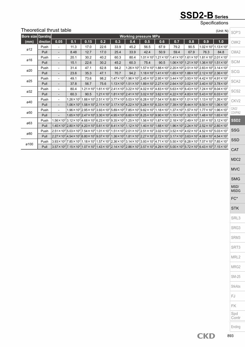
Theoretical thrust table
SSD2-B SeriesSpecifications
Bore size (mm)
Operating direction
Working pressure MPa0.05 0.1 0.15 0.2 0.3 0.4 0.5 0.6 0.7 0.8 0.9 1.0
ø12Push - 11.3 17.0 22.6 33.9 45.2 56.5 67.9 79.2 90.5 1.02×10² 1.13×10²
Pull - 8.48 12.7 17.0 25.4 33.9 42.4 50.9 59.4 67.9 76.3 84.8
ø16Push - 20.1 30.2 40.2 60.3 80.4 1.01×10² 1.21×10² 1.41×10² 1.61×10² 1.81×10² 2.01×10²
Pull - 15.1 22.6 30.2 45.2 60.3 75.4 90.5 1.06×10² 1.21×10² 1.36×10² 1.51×10²
ø20Push - 31.4 47.1 62.8 94.2 1.26×10² 1.57×10² 1.88×10² 2.20×10² 2.51×10² 2.83×10² 3.14×10²
Pull - 23.6 35.3 47.1 70.7 94.2 1.18×10² 1.41×10² 1.65×10² 1.88×10² 2.12×10² 2.36×10²
ø25Push - 49.1 73.6 98.2 1.47×10² 1.96×10² 2.45×10² 2.95×10² 3.44×10² 3.93×10² 4.42×10² 4.91×10²
Pull - 37.8 56.7 75.6 1.13×10² 1.51×10² 1.89×10² 2.27×10² 2.64×10² 3.02×10² 3.40×10² 3.78×10²
ø32Push - 80.4 1.21×10² 1.61×10² 2.41×10² 3.22×10² 4.02×10² 4.83×10² 5.63×10² 6.43×10² 7.24×10² 8.04×10²
Pull - 60.3 90.5 1.21×10² 1.81×10² 2.41×10² 3.02×10² 3.62×10² 4.22×10² 4.83×10² 5.43×10² 6.03×10²
ø40Push - 1.26×10² 1.88×10² 2.51×10² 3.77×10² 5.03×10² 6.28×10² 7.54×10² 8.80×10² 1.01×10³ 1.13×10³ 1.26×10³
Pull - 1.06×10² 1.58×10² 2.11×10² 3.17×10² 4.22×10² 5.28×10² 6.33×10² 7.39×10² 8.44×10² 9.50×10² 1.06×10³
ø50Push - 1.96×10² 2.95×10² 3.93×10² 5.89×10² 7.85×10² 9.82×10² 1.18×10³ 1.37×10³ 1.57×10³ 1.77×10³ 1.96×10³
Pull - 1.65×10² 2.47×10² 3.30×10² 4.95×10² 6.60×10² 8.25×10² 9.90×10² 1.15×10³ 1.32×10³ 1.48×10³ 1.65×10³
ø63Push 1.56×10² 3.12×10² 4.68×10² 6.23×10² 9.35×10² 1.25×10³ 1.56×10³ 1.87×10³ 2.18×10³ 2.49×10³ 2.81×10³ 3.12×10³
Pull 1.40×10² 2.80×10² 4.20×10² 5.61×10² 8.41×10² 1.12×10³ 1.40×10³ 1.68×10³ 1.96×10³ 2.24×10³ 2.52×10³ 2.80×10³
ø80Push 2.51×10² 5.03×10² 7.54×10² 1.01×10³ 1.51×10³ 2.01×10³ 2.51×10³ 3.02×10³ 3.52×10³ 4.02×10³ 4.52×10³ 5.03×10³
Pull 2.27×10² 4.54×10² 6.80×10² 9.07×10² 1.36×10³ 1.81×10³ 2.27×10³ 2.72×10³ 3.17×10³ 3.63×10³ 4.08×10³ 4.54×10³
ø100Push 3.93×10² 7.85×10² 1.18×10³ 1.57×10³ 2.36×10³ 3.14×10³ 3.93×10³ 4.71×10³ 5.50×10³ 6.28×10³ 7.07×10³ 7.85×10³
Pull 3.57×10² 7.15×10² 1.07×10³ 1.43×10³ 2.14×10³ 2.86×10³ 3.57×10³ 4.29×10³ 5.00×10³ 5.72×10³ 6.43×10³ 7.15×10³
(Unit: N) SCP*3
CMK2
CMA2
SCM
SCG
SCA2
SCS2
CKV2
CAV2/COVP/N2
SSD2
SSG
SSD
CAT
MDC2
MVC
SMG
MSD/MSDG
FC*
STK
SRL3
SRG3
SRM3
SRT3
MRL2
MRG2
SM‑25
ShkAbs
FJ
FK
SpdContr
Ending
893

Precautions for model No. selection*1 : When two cylinders are connected, the connection is from Cylinder 2 side.
(Refer to dimensions) Determine cylinders 1 and 2 with the mounting method in mind.*2 : The T2YD* switch cannot be installed on ø12 and ø16. In addition, T8*
switch cannot be installed on ø12 to ø32.*3 : Piston rod of ø12 to ø25 is stainless steel as standard. C type snap ring is stainless steel instead of steel. The rod end male thread nut is stainless steel.*4 : Refer to pages 750 and 751 for combinations of variations/options.*5 : Option “N” will be inscribed on both S1 and S2 sides, but for all other
option codes, they will only be written on S2.*6 : Two units are included when an accessory is selected. One unit each is
included when “IY” is selected.*7 : The F type switch with L type lead wire on ø20 models cannot be selected
on stroke lengths of 15 mm or under.*8 : Switches are shipped with the product. Contact CKD if assembling before
shipment is necessary.*9 : When S1 stroke length is at or below that in the table below, the length of
the usable mounting bolts will differ from the standard and so contact CKD.
*10 : F type switch cannot be selected.
[Example of model No.]SSD2-BL-12-5-T0H-R-N-10-T0H-R-NModel: Compact cylinder, back to backB Bore size : ø12 mmC Port thread : Rc threadD Stroke length S1 : 5 mmE Switch model No. : Reed switch T0H,
lead wire 1 mF Switch quantity : 1 on rod sideC Option : Rod end male threadD Stroke length S2 : 10 mmE Switch model No. : Reed switch T0H,
lead wire 1 mF Switch quantity : 1 on rod sideG Option : Rod end male thread
SSD2-B Series
Model No.A
How to orderWithout switch (without magnet for switch)
With switch (built-in magnet for switch)
12 N5
*2/*7/*8Switch model No.E
Stroke lengthD
Port threadC
Bore size
B
12 R
N I10
Cylinder 1 stroke length
S1 S2
Cylinder 1
5 N R10
Accessory*6
H
Switch quantityF
N
Switch quantityF
OptionG
I
Cylinder 2
Option*3*5
G
Cylinder 2 stroke length
Code DescriptionModel No.
SSD2-B Double acting/back to backSSD2-BL Double acting/back to back/with switch
Bore size (mm)12 ø1216 ø1620 ø2025 ø2532 ø3240 ø4050 ø5063 ø6380 ø80100 ø100
Port threadBlank Rc thread
NN NPT thread (ø32 and over) (made-to-order product)GN G thread (ø32 and over) (made-to-order product)
Stroke length (mm)Refer to the stroke length table on the following page.
* Lead wire lengthBlank 1 m (standard)
3 3 m (option)5 5 m (option) *9
Switch quantityR 1 on rod sideH 1 on head sideD 2
OptionBlank Rod end female thread
N Rod end male threadM *3 Piston rod material (stainless steel)
Accessory (available when rod end male thread “N” is selected)I Rod eyeY Rod clevis (pin and snap ring included)
A
B
C
D
F
G
H
Switch model No.Lead wire Lead wire
Conta
ct Voltage Display Lead wire
Bore sizeStraight L-shaped AC DC 12 16 20 25 32 40 50 63 80 100
- F2S*P
roxi
mity
1-color display
2-wire - F3S* 3-wire
F2H* F2V* 2-wire F3H* F3V* 3-wire
F3PH* F3PV* 1 color display (PNP output) (custom) 3-wire
F2YH* F2YV* 2-color display 2-wire
F3YH* F3YV* 3-wire T0H* T0V*
Ree
d 1-color display2-wire
T5H* T5V* no indicator lamp T8H* T8V* 1-color display T1H* T1V*
Pro
xim
ity
1-color display
2-wire
T2H* T2V* T3H* T3V*
3-wire
T3PH* T3PV* 1-color display(PNP output)
T2WH* T2WV* 2-color display
2-wire
T2YH* T2YV* T3WH* T3WV*
3-wire
T3YH* T3YV* T2YD* - 2-color display (AC
magnetic field) 2-wire
T2YDT* -
T2JH* T2JV* 1-color display off-delay 2-wire
E
SSD2-B
SSD2-BL T0H T0H
Bore sizeWithout switch With switch
S1 Stroke lengthø20 10 or less -ø25 5 or less -ø32 5 or less -ø50 5 or less -ø63 15 or less 5 or lessø80 20 or less 10 or lessø100 10 or less -
Cylinder 1Cylinder 1 stroke length
S1+S2+ Cylinder 2 stroke length
5 mm (S1)10 mm
Total stroke 15 mm
Cylinder 2
Cylinder 1 Cylinder 2
(S2)
S1 S2
SCP*3
CMK2
CMA2
SCM
SCG
SCA2
SCS2
CKV2
CAV2/COVP/N2
SSD2
SSG
SSD
CAT
MDC2
MVC
SMG
MSD/MSDG
FC*
STK
SRL3
SRG3
SRM3
SRT3
MRL2
MRG2
SM‑25
ShkAbs
FJ
FK
SpdContr
Ending
894

Stroke length (mm)Applicable bore size
12 16 20 25 32 40 50 63 80 100
Sta
ndar
d st
roke
leng
th
5 10 15 20 25 30 35 40 45 50 75 100
Min. stroke length (mm) *1 1Max. stroke length (mm) 30 50 100Custom stroke length *2 In 1 mm increments
*1 : Less than 5 mm for 1-color display switch and less than 10 mm for the 2-color display, off-delay, AC magnetic field proof, T1* or T8* switch are not available.
Refer to page 890 for the min. stroke length with switch.*2 : The total length when using a custom stroke length is the same as that when using the next longer standard
stroke length.
SSD2-B SeriesHow to order
How to order switch
Switch model No. (Item E on page 894)
SW
[Stroke length table]
T0H
SCP*3
CMK2
CMA2
SCM
SCG
SCA2
SCS2
CKV2
CAV2/COVP/N2
SSD2
SSG
SSD
CAT
MDC2
MVC
SMG
MSD/MSDG
FC*
STK
SRL3
SRG3
SRM3
SRT3
MRL2
MRG2
SM‑25
ShkAbs
FJ
FK
SpdContr
Ending
895
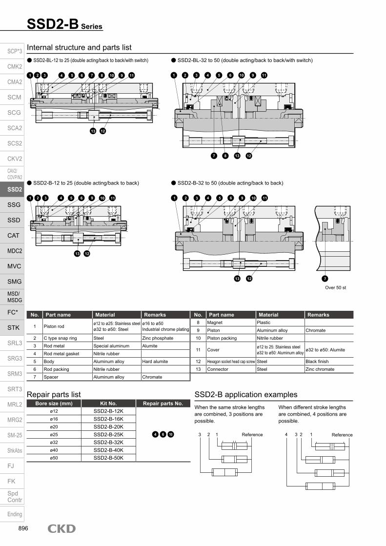
Internal structure and parts list SSD2-BL-12 to 25 (double acting/back to back/with switch)
SSD2-B Series
SSD2-BL-32 to 50 (double acting/back to back/with switch)
SSD2-B-12 to 25 (double acting/back to back) SSD2-B-32 to 50 (double acting/back to back)
No. Part name Material Remarks No. Part name Material Remarks
1 Piston rod ø12 to ø25: Stainless steel ø32 to ø50: Steel
ø16 to ø50Industrial chrome plating
8 Magnet Plastic
9 Piston Aluminum alloy Chromate
2 C type snap ring Steel Zinc phosphate 10 Piston packing Nitrile rubber
3 Rod metal Special aluminum Alumite11 Cover ø12 to 25: Stainless steel
ø32 to ø50: Aluminum alloy ø32 to ø50: Alumite4 Rod metal gasket Nitrile rubber
5 Body Aluminum alloy Hard alumite 12 Hexagon socket head cap screw Steel Black finish
6 Rod packing Nitrile rubber 13 Connector Steel Zinc chromate
7 Spacer Aluminum alloy Chromate
Bore size (mm) Kit No. Repair parts No.ø12 SSD2-B-12K
4 6 10
ø16 SSD2-B-16Kø20 SSD2-B-20Kø25 SSD2-B-25Kø32 SSD2-B-32Kø40 SSD2-B-40Kø50 SSD2-B-50K
Repair parts list SSD2-B application examplesWhen the same stroke lengths are combined, 3 positions are possible.
When different stroke lengths are combined, 4 positions are possible.
123 Reference 1234 Reference
1 2 3 4 5 6 7 8 10 9 11
13 12
1 2 3 4 5 6 9 10 11
13 12
1 2 3 4 5 6 9 10 11
713 12
Over 50 st
1 2 3 4 5 6 10 9 11
13 127 8
SCP*3
CMK2
CMA2
SCM
SCG
SCA2
SCS2
CKV2
CAV2/COVP/N2
SSD2
SSG
SSD
CAT
MDC2
MVC
SMG
MSD/MSDG
FC*
STK
SRL3
SRG3
SRM3
SRT3
MRL2
MRG2
SM‑25
ShkAbs
FJ
FK
SpdContr
Ending
896

SSD2-B SeriesInternal structure and parts list
Internal structure and parts list SSD2-BL-63 to 100 (double acting/back to back/with switch)
SSD2-B-63 to 100 (double acting/back to back)
No. Part name Material Remarks No. Part name Material Remarks1 Piston rod Steel Industrial chrome plating 8 Magnet Plastic
2 C type snap ring Steel Zinc phosphate 9 Piston Aluminum alloy Chromate
3 Rod metal Aluminum alloy Chromate 10 Piston packing Nitrile rubber
4 Rod metal gasket Nitrile rubber 11 Cover Aluminum alloy Alumite
5 Body Aluminum alloy Hard alumite 12 Bush Oiles drymet *1
6 Rod packing Nitrile rubber 13 Hexagon socket head cap screw Steel Black finish
7 Spacer Aluminum alloy Chromate 14 Connector Steel Zinc chromate
Bore size (mm) Kit No. Repair parts No.ø63 SSD2-B-63K
4 6 10ø80 SSD2-B-80Kø100 SSD2-B-100K
Repair parts list
*1: Material is steel for copper and PTFE free specifications.
1 2 3 4 6 5 12 7 8 10 9 11
14 13
1 2 3 4 6 5 12 9 10 11 7
14 13
Over 50 st
SCP*3
CMK2
CMA2
SCM
SCG
SCA2
SCS2
CKV2
CAV2/COVP/N2
SSD2
SSG
SSD
CAT
MDC2
MVC
SMG
MSD/MSDG
FC*
STK
SRL3
SRG3
SRM3
SRT3
MRL2
MRG2
SM‑25
ShkAbs
FJ
FK
SpdContr
Ending
897

SSD2-B Series
Switch dimensions
Reed T0H/T0V,T5H/T5V *6
Proximity T2H/T2V,T3H/T3V *6
Proximity T2WH/T2WV,T3WH/T3WV *6
Proximity F2H/F2V, F3H/F3V,F2YH/F2YV, F3YH/F3YV Proximity F2S/F3S
Bore size (mm) HD RD HD RD HD RD HD RD HD RDø12 1.5 1.5 1.5 1.5 3.5 3.5ø16 0 4 0 4.5 1 6ø20 3 7.5 3 7.5 5 9.5 7.5 12 6.5 11ø25 4 9.5 4 9.5 6 11.5 8.5 14 7.5 13
Codea’ c’ H kk’ M MM T wf
Bore size (mm)ø12 10.5 9 8 M5 5 6 3.2 3.5
ø16 12 10 10 M6 6 8 3.6 3.5
ø20 14 12 13 M8 8 10 5 4.5
ø25 17.5 15 17 M10×1.25 10 12 6 5
Rod end male thread
*1 : To calculate A + S1 + S2, B + S1 or B + S2 when using custom stroke length, apply the next longer standard stroke length (instead of the custom stroke length) to the stroke length.
(Example) If the custom stroke length is 7 mm, apply the standard stroke length of 10 mm.*2 : HD and RD dimensions for 5 mm stroke length differ from these dimensions according to the setting.*3 : Refer to page 1044 for HD, RD and protruding dimensions of the 2-color display, off-delay, AC magnetic field proof, T1* and T8* switches.*4 : Dimensions in ( ) of FA are for the radial lead wire.*5 : For dimensions of individual accessories, refer to pages 1046 to 1049.*6 : Only F type switch is available for the ø20 or ø25 piping port surface.
Code Common dimensions with switchBore size (mm) A *1 B *1 C D EE F FA *4 FB J K KA KK M MM N WF
ø12 51 22 5.5 5.5 M5 25 13(16.5) 4.5 6.5 spot face depth 3.5 32 M4 depth 7 M3 depth 6 5 6 15.5 3.5ø16 51 22 5.5 5.5 M5 29 15(18.5) 4.5 6.5 spot face depth 3.5 38 M4 depth 7 M4 depth 8 6 8 20 3.5ø20 68 29.5 8 5.5 M5 36 18.5(22) 12.5 9 spot face depth 5.5 47 M6 depth 11 M5 depth 7 8 10 25.5 4.5ø25 75 32.5 11 6 M5 40 20.5(24) 13.5 9 spot face depth 5.5 51 M6 depth 11 M6 depth 12 10 12 28 5
Rod end male thread
Dimensions SSD2-BL-12/16 (with switch)
SSD2-BL-25, 32 (with switch)
a’c’
T
wf
øMM
kk’Width across flats M
Width across flats H
FN4-J
Mounting hole
F N
MøK
WF
KK
øMM
RD4-KA
HD
øMM
Cylinder 1 Cylinder 2
A+S1+S2B+S1 B+S2
D D
HDC
RD
WF4-EE
F
N4-JMounting hole
F N
MøK
KK
øMM
4-KA
øMM
C Cylinder 1 Cylinder 2
A+S1+S2
B+S1 B+S2
D D C
WF4-EE
RDFA
WF
FB
HD
HD RD
C
FAFB
SCP*3
CMK2
CMA2
SCM
SCG
SCA2
SCS2
CKV2
CAV2/COVP/N2
SSD2
SSG
SSD
CAT
MDC2
MVC
SMG
MSD/MSDG
FC*
STK
SRL3
SRG3
SRM3
SRT3
MRL2
MRG2
SM‑25
ShkAbs
FJ
FK
SpdContr
Ending
898

SSD2-B SeriesDouble acting/back to back
Code Dimensions without switch and common dimensionsBore size (mm) A *1 B *1 C D EE F J K KA KK M MM N WF
ø12 41 17 5.5 5.5 M5 25 6.5 spot face depth 3.5 32 M4 depth 7 M3 depth 6 5 6 15.5 3.5
ø16 41 17 5.5 5.5 M5 29 6.5 spot face depth 3.5 38 M4 depth 7 M4 depth 8 6 8 20 3.5
ø20 48 19.5 8 5.5 M5 36 9 spot face depth 5.5 47 M6 depth 11 M5 depth 7 8 10 25.5 4.5
ø25 55 22.5 11 6 M5 40 9 spot face depth 5.5 51 M6 depth 11 M6 depth 12 10 12 28 5
Codea’ c’ H kk’ M MM T wf
Bore size (mm)ø12 10.5 9 8 M5 5 6 3.2 3.5
ø16 12 10 10 M6 6 8 3.6 3.5
ø20 14 12 13 M8 8 10 5 4.5
ø25 17.5 15 17 M10×1.25 10 12 6 5
Rod end male thread
*1 : To calculate A + S1 + S2, B + S1 or B + S2 when using custom stroke length, apply the next longer standard stroke length (instead of the custom stroke length) to the stroke length.
(Example) If the custom stroke length is 7 mm, apply the standard stroke length of 10 mm.*2 : For dimensions of individual accessories, refer to pages 1046 to 1049.
Rod end male thread
Dimensions SSD2-B-12/16 (without switch)
SSD2-B-20, 25 (without switch)
a’c’
T
wf
øMM
kk’Width across flats M
Width across flats H
FN4-J
Mounting hole
F N
MøK
WF
KK
øMM
4-KA
øMM
Cylinder 1 Cylinder 2
A+S1+S2
B+S1 B+S2D D C
WF4-EE
F
N4-J
Mounting hole
F N
MøK
KK
øMM
4-KA
øMM
C Cylinder 1 Cylinder 2
A+S1+S2
B+S1 B+S2
D D C
WF4-EE
WF
C
SCP*3
CMK2
CMA2
SCM
SCG
SCA2
SCS2
CKV2
CAV2/COVP/N2
SSD2
SSG
SSD
CAT
MDC2
MVC
SMG
MSD/MSDG
FC*
STK
SRL3
SRG3
SRM3
SRT3
MRL2
MRG2
SM‑25
ShkAbs
FJ
FK
SpdContr
Ending
899

Codea’ c’ H kk’ M MM T wf
Bore size (mm)ø32 23.5 20.5 22 M14×1.5 14 16 8 5
ø40 23.5 20.5 22 M14×1.5 14 16 8 5
ø50 28.5 26 27 M18×1.5 17 20 11 5
ø63 28.5 26 27 M18×1.5 17 20 11 5
ø80 35.5 32.5 32 M22×1.5 22 25 13 8
ø100 35.5 32.5 41 M26×1.5 27 30 16 8
Rod end male thread
Code Without switch Common dimensions with switchBore size (mm) A *1, *6 B *1, *6 A *1 B *1 C *8 D *8 EE F FA *4 FB G H J K
ø32 60(80) 23(33) 80 33 8(10) 8(5.5) Rc1/8 *7 45 23(26.5) 20.5 49.5 12.5 9 spot face depth 5.5 60
ø40 73(93) 29.5(39.5) 93 39.5 12(11.5) 8.5(8) Rc1/8 52 26.5(30) 27.5 57 15 9 spot face depth 5.5 69
ø50 77(97) 30.5(40.5) 97 40.5 10.5 10.5 Rc1/4 64 32.5(36) 28.5 71 18 11 spot face depth 6.5 86
ø63 88(108) 36(46) 108 46 13 11 Rc1/4 77 39(42.5) 28.5 84 23 14 spot face depth 9 103
ø80 107(127) 43.5(53.5) 127 53.5 16 13 Rc3/8 98 49.5(53) 28.5 104 31 17.5 spot face depth 11 132
ø100 130(150) 53(63) 150 63 23 15 Rc3/8 117 59(62.5) 28.5 123.5 38 17.5 spot face depth 11 156
Code Common dimensions with switch Reed T0H/T0V,T5H/T5V
Proximity T2H/T2V,T3H/T3V
Proximity T2WH/T2WV,T3WH T3WV
Bore size (mm) KA KK M MM N O WF HD *2 RD *2 HD *2 RD *2 HD RDø32 M6 depth 11 M8 depth 13 14 16 34 4.5 7 4 9.5 4 9.5 6 11.5
ø40 M6 depth 11 M8 depth 13 14 16 40 5 7 7 12 7 12 8.5 13.5
ø50 M8 depth 13 M10 depth 15 17 20 50 7 8 7.5 12.5 7.5 12.5 9 14
ø63 M10 depth 25 M10 depth 15 17 20 60 7 8 12.5 13 12.5 13 14 14.5
ø80 M12 depth 28 M16 depth 21 22 25 77 6 10 17.5 15.5 17.5 15.5 19 17
ø100 M12 depth 28 M20 depth 27 27 30 94 6.5 12 23 19.5 23 19.5 24.5 21
SSD2-B Series
Rod end male thread
Dimensions SSD2-BL-32 to 100 (with switch)
SSD2-B-32 to 100 (without switch)
*1 : To calculate A + S1 + S2, B + S1 or B + S2 when using custom stroke length, apply the next longer standard stroke length (instead of the custom stroke length) to the stroke length. (Example) If the custom stroke length is 7 mm, apply the standard stroke length of 10 mm.
*2 : HD and RD dimensions for 5 mm stroke length differ from these dimensions according to the setting.*3 : Refer to page 1044 for HD, RD and protruding dimensions of the 2-color display, off-delay, AC magnetic field proof, T1* and T8* switches.*4 : Dimensions in ( ) of FA are for the radial lead wire.*5 : For dimensions of individual accessories, refer to pages 1046 to 1049.*6 : Dimensions in ( ) of codes A and B are for stroke lengths of more than 50 mm.*7 : The ø32 bore size with a 5 mm stroke and without a switch has a port size of M5.*8 : Dimensions in ( ) of codes C and D are when the value is for a 5 mm stroke without switch.
a’c’
T
wf
øMM
kk’Width across flats M
Width across flats H
FNH
4-JMounting hole
OG F N
MøK
WF
KK
øMM
RD 4-KA HD
øMM
C
Cylinder 1 Cylinder 2
A+S1+S2B+S1 B+S2
D DHD
CRD
WF
4-EE
FNH
4-JMounting hole
OG F N
MøK
WF
KK
øMM
4-KA
øMM
CCylinder 1 Cylinder 2
A+S1+S2B+S1 B+S2
D D CWF
4-EE
FB
FA
SCP*3
CMK2
CMA2
SCM
SCG
SCA2
SCS2
CKV2
CAV2/COVP/N2
SSD2
SSG
SSD
CAT
MDC2
MVC
SMG
MSD/MSDG
FC*
STK
SRL3
SRG3
SRM3
SRT3
MRL2
MRG2
SM‑25
ShkAbs
FJ
FK
SpdContr
Ending
900

M E M OM E M OSCP*3
CMK2
CMA2
SCM
SCG
SCA2
SCS2
CKV2
CAV2/COVP/N2
SSD2
SSG
SSD
CAT
MDC2
MVC
SMG
MSD/MSDG
FC*
STK
SRL3
SRG3
SRM3
SRT3
MRL2
MRG2
SM‑25
ShkAbs
FJ
FK
SpdContr
Ending
901

Compact cylinder double acting/two-stage
SSD2-W Series Bore size: ø12/ø16/ø20/ø25/ø32/ø40/ø50/ø63/ø80/ø100
Specifications
*1: The max. working pressure is 0.5 MPa when S1 and S2 are the same value.*2: The ø32 bore size with a 5 mm stroke and without a switch has a port size of M5.
Item SSD2-WSSD2-WL (with switch)
Bore size mm ø12 ø16 ø20 ø25 ø32 ø40 ø50 ø63 ø80 ø100Actuation Double acting/two-stageWorking fluid Compressed airMax. working pressure MPa 1.0 (≈150 psi, 10 bar) (*1)Min. working pressure MPa 0.15 (≈22 psi, 1.5 bar) 0.1 (≈15 psi, 1 bar)Proof pressure MPa 1.6 (≈230 psi, 16 bar)Ambient temperature °C -10 (14°F) to 60 (140°F) (no freezing)Port size M5 Rc1/8 (*2) Rc1/4 Rc3/8Stroke tolerance mm S1= +1.0
0 S2= 0-1.5
Working piston speed mm/s 50 to 500 50 to 300Cushion NoneLubrication Not required (use turbine oil ISO VG32 if necessary for lubrication)Allowable absorbed energy J 0.004 0.01 0.016 0.021 0.025 0.092 0.1 0.12 0.27 0.56
Stroke length
*1: The custom stroke length is available in 1 mm increments. However, the total length is the same as that of the next longer standard stroke length.
*2: When using the type with switch, refer to the table on the right.
Bore size (mm)
Standard stroke length(mm)
Max. stroke length (mm)
Min. stroke length (mm)
ø12 5/10/15/2025/30
30
1
ø16ø20
5/10/15/20/2530/35/40/45/50
50ø25ø32ø40ø50
10/15/20/2530/35/40/45/50
50ø63ø80ø100
Min. stroke length with switch (2 switches)
*1: Less than 10 mm with the 2-color display, off-delay, AC magnetic field proof, T1* or T8* switch is not available.
*2: Values in ( ) are for the type with 1 on rod side.
Bore size(mm) T0H/V / T5H/V T2H/V / T3H/V
ø1210(5)
5
ø16ø20
5
ø25ø32ø40ø50ø63ø80ø100
Custom stroke length SSD2-W Series
ItemStandard products
Standard stroke length body with spacerModel No. Refer to How to order.
DescriptionA spacer is added to the standard stroke length body to adjust the stroke length in 1 mm increments.
Stroke range
Bore size Stroke range12/16 1 to 29
20 to 25 1 to 4932 to 100 1 to 99
Example of model No.Model No.: SSD2-W-32-38A +2 mm spacer is added to the SSD2-W-32-40 standard cylinder to create 38 mm stroke length. B + stroke length is 63mm.
A + stroke length
B + stroke length
SCP*3
CMK2
CMA2
SCM
SCG
SCA2
SCS2
CKV2
CAV2/COVP/N2
SSD2
SSG
SSD
CAT
MDC2
MVC
SMG
MSD/MSDG
FC*
STK
SRL3
SRG3
SRM3
SRT3
MRL2
MRG2
SM‑25
ShkAbs
FJ
FK
SpdContr
Ending
902

SSD2-W SeriesSpecifications
Switch specifications (F type switch) 1-color/2-color display
ItemProximity 2-wire Proximity 3-wire Proximity 2-wire Proximity 3-wire
F2S F3S F2H/F2VF2YH/F2YV
F3H/F3V F3PH/F3PV (made to order)
F3YH/F3YV
Applications Dedicated for programmable controller
For programmable controller, relay
Dedicated for programmable controller
For programmable controller, relay
Output method - NPN output - NPN output PNP output NPN outputPower supply voltage - 10 to 28 VDC - 10 to 28 VDC 4.5 to 28 VDC 10 to 28 VDCLoad voltage 10 to 30 VDC 30 VDC or less 10 to 30 VDC 24 VDC ±10% 30 VDC or lessLoad current 5 to 20 mA 50 mA or less 5 to 20 mA 50 mA or less
Indicator lamp LED(Lit when ON)
Yellow LED(Lit when ON)
Red/greenLED
(Lit when ON)
Yellow LED(Lit when ON)
Red/greenLED
(Lit when ON)Leakage current 1 mA or less 10 μA or less 1 mA or less 10 μA or lessWeight g 1 m:10 3 m:29
Switch specifications (T type switch) 1-color/2-color display/for AC magnetic field proof
ItemProximity 2-wire Proximity 2-wire Proximity 3-wire Reed 2-wire Proximity 2-wire
T1H/T1V
T2H/T2V/T2JH/T2JV
T2YH/T2YV
T2WH/T2WV
T3H/T3V
T3PH/T3PV
T3YH/T3YV
T3WH/T3WV
T0H/T0V T5H/T5V T8H/T8VT2YD(*4)T2YDT
ApplicationsFor programmable
controller, relay, compact solenoid valve
Dedicated for programmable controller
For programmable controller, relay
For programmable controller, relay
For programmable controller, relay, IC circuit (no indicator
lamp), serial connection
For programmable controller, relay
Dedicated for programmable
controllerOutput method - NPN output PNP output NPN output NPN output -Pwr. supp. V. - 10 to 28 VDC -Load voltage 85 to 265 VAC 10 to 30 VDC 24 VDC ±10% 30 VDC or less 12/24 VDC 100/110 VAC 5/12/24 VDC 100/110 VAC 12/24 VDC 110 VAC 220 VAC 24 VDC ±10%Load current 5 to 100 mA 5 to 20 mA (*3) 100 mA or less 50 mA or less 5 to 50 mA 7 to 20 mA 50 mA or less 20 mA or less 5 to 50 mA 7 to 20 mA 7 to 10 mA 5 to 20 mA
Indicator lamp
LED(Lit when
ON)
LED(Lit when
ON)
Red/green LED
(Lit when ON)
Red/green LED
(Lit when ON)
LED(Lit when
ON)
Yellow LED
(Lit when ON)
Red/green LED
(Lit when ON)
Red/green LED
(Lit when ON)
LED(Lit when ON)
Without indicator lamp
LED(Lit when ON)
Red/green LED
(Lit when ON)Leakage current
≤ 1 mA at 100 VAC, ≤ 2 mA at 200 VAC
1 mA or less 10 μA or less 0 mA1 mA or
less
Weight g1 m:333 m:875 m:142
1 m:183 m:495 m:80
1 m:333 m:875 m:142
1 m:183 m:495 m:80
1 m:183 m:495 m:80
1 m:333 m:875 m:142
1 m:183 m:495 m:80
1 m:18 3 m:49 5 m:801 m:333 m:875 m:142
1 m:613 m:1665 m:272
*1 : Refer to Ending Page 1 for detailed switch specifications and dimensions. *2 : Switches other than the above models, such as switches with connectors, are also available. Refer to Ending Page 1. *3 : The max. load current is 20 mA at 25°C. The current is lower than 20 mA if the operating ambient temperature around the switch is higher than 25˚C.
(5 to 10 mA at 60°C) *4 : Switch for AC magnetic field (T2YD/T2YDT) cannot be used in DC magnetic field. *5 : The F type switch uses a bend-resistant lead wire.
Total cylinder weight Total weight = weight of cylinder 1 + weight of cylinder 2.[Example: Total weight of SSD-W-25-30-N-10-N]
Weight of ø25 with 30 mm stroke length:····(1) Weight of ø25 with 10 mm stroke length:····(2) Total weight = (1) + (2) = 168 g + 105 g = 273 g
Cylinder weight table (the weight of the switches is when there are 2 cylinder switches.)
Stroke length (mm) 5 10 15 20 25 30 35 40 45 50 75 100Bore size (mm) No switch Switch No switch Switch No switch Switch No switch Switch No switch Switch No switch Switch No switch Switch No switch Switch No switch Switch No switch Switch No switch Switch No switch Switch
ø12 37 87 45 87 54 96 62 104 71 113 73 115 - - - - - - - - - - - -ø16 49 105 60 105 70 115 81 126 92 137 103 148 - - - - - - - - - - - -ø20 65 120 77 152 90 165 103 178 115 190 128 203 141 216 154 229 167 242 205 280 - - - -ø25 90 181 105 196 121 212 137 228 163 244 168 259 184 275 200 291 216 307 231 322 - - - -ø32 126 240 148 262 170 284 192 306 213 327 235 349 257 371 279 393 301 415 322 436 494 542 604 652ø40 189 332 216 359 242 385 269 412 296 439 322 465 348 491 375 518 401 544 478 571 646 695 776 825ø50 - - 354 548 396 590 438 632 480 674 523 717 565 759 607 801 649 843 691 885 1038 1095 1248 1305ø63 - - 543 822 598 877 653 932 708 987 763 1042 818 1097 874 1153 929 1208 984 1263 1474 1538 1749 1813ø80 - - 1002 1415 1089 1502 1175 1588 1262 1675 1348 1961 1435 1848 1522 1935 1609 2022 1695 2108 2475 2541 2907 2973
ø100 - - 1558 2125 1672 2239 1785 2352 1899 2466 2013 2580 2127 2694 2240 2807 2354 2921 2468 3035 3531 3603 4098 4170
(Unit: g)
SCP*3
CMK2
CMA2
SCM
SCG
SCA2
SCS2
CKV2
CAV2/COVP/N2
SSD2
SSG
SSD
CAT
MDC2
MVC
SMG
MSD/MSDG
FC*
STK
SRL3
SRG3
SRM3
SRT3
MRL2
MRG2
SM‑25
ShkAbs
FJ
FK
SpdContr
Ending
903

SSD2-W Series
Precautions for model No. selection*1 : T2YD* switch cannot be installed on ø12 and ø16. In
addition, T8* switch cannot be installed on ø12 to ø32.
*2 : Piston rod of ø12 to ø25 is stainless steel as standard. C type snap ring is stainless steel instead of steel. The rod end male thread nut is stainless steel.
*3 : Refer to pages 750 and 751 for combinations of variations/options.
*4 : Switches are shipped with the product. Contact CKD if assembling before shipment is necessary.
*5 : F type switch cannot be selected.
[Example of model No.]SSD2-WL-12-30-T0H-R-N-5-T0H-R-IModel: Compact cylinder two-stageB Bore size : ø12 mmC Port thread : Rc threadD Total stroke length S1 : 30 mmE Switch model No. : Reed switch T0H,
lead wire 1 mF Switch quantity : 1 on rod sideG Option 1 : Rod end male threadD 1st stage stroke length S2 : 5 mm 2nd stage stroke length : 25 mmE Switch model No. : Reed switch T0H,
lead wire 1 mF Switch quantity : 1 on rod sideI Accessory : Rod eye
Model No.A
How to orderWithout switch (without magnet for switch)
With switch (built-in magnet for switch)
12 N30
*1*4
Switch model No.E
Stroke lengthD
Port threadC
Bore sizeB
12 R
Code DescriptionModel No.
SSD2-W Double acting/two-stageSSD2-WL Double acting/two-stage/with switch
Bore size (mm)12 ø1216 ø1620 ø2025 ø2532 ø3240 ø4050 ø5063 ø6380 ø80100 ø100
Port threadBlank Rc thread
NN NPT thread (ø32 and over) (made-to-order product)GN G thread (ø32 and over) (made-to-order product)
Stroke length (mm)Refer to the stroke length table on the following page.
* Lead wire lengthBlank 1 m (standard)
3 3 m (option)5 5 m (option) *5
Switch quantityR 1 on rod sideH 1 on head sideD 2
Option 1Blank Rod end female thread
N Rod end male thread
Option 2 *2M Piston rod material (stainless steel)
Accessory (available when rod end male thread “N” is selected)I Rod eyeY Rod clevis (pin and snap ring included)
A
B
C
D
F
G
I
H
Switch model No.Lead wire Lead wire
Conta
ct Voltage Display Lead wire
Bore sizeStraight L-shaped AC DC 12 16 20 25 32 40 50 63 80 100
- F2S*P
roxi
mity
1-color display
2-wire - F3S* 3-wire
F2H* F2V* 2-wire F3H* F3V* 3-wire
F3PH* F3PV* 1 color display (PNP output) (custom) 3-wire
F2YH* F2YV* 2-color display
2-wire F3YH* F3YV* 3-wire T0H* T0V*
Ree
d 1-color display2-wire
T5H* T5V* no indicator lamp T8H* T8V* 1-color display T1H* T1V*
Pro
xim
ity
1-color display
2-wire
T2H* T2V* T3H* T3V*
3-wire
T3PH* T3PV* 1-color display(PNP output)
T2WH* T2WV* 2-color display
2-wire
T2YH* T2YV* T3WH* T3WV*
3-wire
T3YH* T3YV* T2YD* - 2-color display
(AC magnetic field) 2-wire
T2YDT* -
T2JH* T2JV* 1-color display off-delay 2-wire
E
M I5Total stroke 1st stage stroke length
S1 S2
Cylinder 1
30 N R5
AccessoryI
Switch quantityF
M
Switch quantityF
Option 2*2
H
I
Cylinder 2
Option 1*2
G
Cylinder 1
1st stage stroke length
(S1)+ 2nd stage stroke length
5 mm (S2)25 mm
Total stroke length 30 mm
Cylinder 2
SSD2-W
SSD2-WL T0HT0H
S1 S2
SCP*3
CMK2
CMA2
SCM
SCG
SCA2
SCS2
CKV2
CAV2/COVP/N2
SSD2
SSG
SSD
CAT
MDC2
MVC
SMG
MSD/MSDG
FC*
STK
SRL3
SRG3
SRM3
SRT3
MRL2
MRG2
SM‑25
ShkAbs
FJ
FK
SpdContr
Ending
904

SSD2-W SeriesHow to order
Stroke length (mm)Applicable bore size
ø12 ø16 ø20 ø25 ø32 ø40 ø50 ø63 ø80 ø100
Sta
ndar
d st
roke
leng
th
5 10 15 20 25 30 35 40 45 50
Min. stroke length (mm) 1Max. stroke length (mm) 30 50Custom stroke length *1 In 1 mm increments
*1 : Less than 5 mm with 1-color display switch and less than 10 mm with the 2-color display, off-delay, AC magnetic field proof, T1* or T8* switch are not available.
Refer to page 902 for the number of installed switches and the min. stroke length.*2 : The total length is the same as that of the next longer standard stroke length.
How to order switch
Switch model No. (Item E on page 904)
[Stroke length table]
SW T0H
SCP*3
CMK2
CMA2
SCM
SCG
SCA2
SCS2
CKV2
CAV2/COVP/N2
SSD2
SSG
SSD
CAT
MDC2
MVC
SMG
MSD/MSDG
FC*
STK
SRL3
SRG3
SRM3
SRT3
MRL2
MRG2
SM‑25
ShkAbs
FJ
FK
SpdContr
Ending
905

SSD2-W Series
Internal structure and parts list SSD2-WL-12 to 50 (double acting/two-stage/with switch)
SSD2-W-63 to 100 (double acting/two-stage) SSD2-W-12 to 50 (double acting/two-stage)
SSD2-WL-63 to 100 (double acting/two-stage/with switch)
Repair parts listBore size (mm) Kit No. Repair parts No.
ø12 SSD2-W-12K
4 6 10
ø16 SSD2-W-16Kø20 SSD2-W-20Kø25 SSD2-W-25Kø32 SSD2-W-32Kø40 SSD2-W-40Kø50 SSD2-W-50Kø63 SSD2-W-63Kø80 SSD2-W-80K
ø100 SSD2-W-100K
No. Part name Material Remarks No. Part name Material Remarks
1 Piston rod ø12 to ø25: Stainless steelø32 to ø100: Steel
ø16 to ø100Industrial chrome plating
9 Piston Aluminum alloy Chromate
10 Piston packing Nitrile rubber
2 C type snap ring Steel Zinc phosphate11 Cover ø12 to 25: Stainless steel
ø32 to ø100: Aluminum alloyø32 to ø100Alumite
3 Rod metal ø12 to ø50: Special aluminumø63 to ø100: Aluminum alloy
ø12 to ø50: Alumiteø63 to ø100: Chromate 12 Plug Stainless steel
4 Rod metal gasket Nitrile rubber 13 Stainless steel mesh Stainless steel
5 Body Aluminum alloy Hard alumite 14 Hexagon socket head cap screw Steel Black finish
6 Rod packing Nitrile rubber 15 Bush Oiles drymet
7 Spacer Aluminum alloy Chromate
8 Magnet Plastic
SSD2-W application examplesPressure setting: P2 > P1 1st stage push
Keeping port 4 pressurized, pressurize port 1.
2nd stage pushKeeping port 1 pressurized, pressurize port 3.
It may not be P2 = P1 depending on the load direction. When using a single acting cylinder with free fall load, ports 2 and 4 in the upper figure and ports 2 and 3 in the lower figure are breathing holes.Port 2, which basically needs no piping as a rule, is plugged with a filter.
1 152 3 4 6 5 12 13 9 10 11
14
1 152 3 4 6 5 12 13 8 10 11
14
7 91 2 4 3 5 6 12
14
7 8 13 9 10 11
1 2 4 3 5 6 12
14
13 9 10 11
P2
3 2 1
4 3 2 1
P1
4
2
32
SCP*3
CMK2
CMA2
SCM
SCG
SCA2
SCS2
CKV2
CAV2/COVP/N2
SSD2
SSG
SSD
CAT
MDC2
MVC
SMG
MSD/MSDG
FC*
STK
SRL3
SRG3
SRM3
SRT3
MRL2
MRG2
SM‑25
ShkAbs
FJ
FK
SpdContr
Ending
906

SSD2-W SeriesDimensions
Rod end male thread
Dimensions SSD2-WL-12 to 25 (with switch T0H/V, T5H/V, T2H/V, T3H/V)
ø12/ø16
ø20/ø25
Codea’ c’ H kk’ M MM T wf
Bore size (mm)ø12 10.5 9 8 M5 5 6 3.2 3.5
ø16 12 10 10 M6 6 8 3.6 3.5
ø20 14 12 13 M8 8 10 5 4.5
ø25 17.5 15 17 M10×1.25 10 12 6 5
Rod end male thread
Code Common dimensions with switchBore size (mm) A B1 B2 C D EE F FA *3 FB I J K KA KK M MM N WF P PP
ø12 52.5 27 22 5.5 5.5 M5 25 13(16.5) 4.5 3.5 6.5 spot face depth 3.5 32 M4 depth 7 M3 depth 6 5 6 15.5 3.5 4.5 M3
ø16 52.5 27 22 5.5 5.5 M5 29 15(18.5) 4.5 3.5 6.5 spot face depth 3.5 38 M4 depth 7 M4 depth 8 6 8 20 3.5 4.5 M3
ø20 70 36 29.5 8 5.5 M5 36 18.5(22) 12.5 5.5 9 spot face depth 5.5 47 M6 depth 11 M5 depth 7 8 10 25.5 4.5 10 M5
ø25 76.5 39 32.5 11 6 M5 40 20.5(24) 13.5 5.5 9 spot face depth 5.5 51 M6 depth 11 M6 depth 12 10 12 28 5 9 M5Switch dimensions
Reed T0H/TOV, T5H/T5V
Proximity T2H/T2V, T3H/T3V
Proximity T2WH/T2WV, T3WH/T3WV
Proximity F2H/F2V, F3H/F3V, F2YH/F2YV, F3YH/F3YV
Bore size (mm) RD1, RD2 HD1 HD2 RD1, RD2 HD1 HD2 RD1, RD2 HD1 HD2 RD1, RD2 HD1 HD2ø12 1.5 6.5 1.5 1.5 6.5 1.5 3.5 8.5 3.5ø16 3.5 4.5 0 3.5 4.5 0 5.5 6.5 1.5ø20 7.5 9.5 3 7.5 9.5 3 9.5 11.5 5 12 14 7.5ø25 9.5 10.5 4 9.5 10.5 4 11.5 12.5 6 14 15 8.5
Switch dimensions
Proximity F2S/F3SProximity T2YH/T2YV/T3YH/T3YV/T2JH/T2JV
AC magnetic field proofT2YD/T2YDT/T1H/T1V
Bore size (mm) RD1, RD2 HD1 HD2 RD1, RD2 HD1 HD2 RD1, RD2 HD1 HD2ø12 - - - - - -ø16 - - - - - -ø20 11 13 6.5 6.5 8.5 2 6.5 8.5 2ø25 13 14 7.5 8.5 9.5 3 8.5 9.5 3
*1 : To calculate A + S1 + S2, B1 + S1 or B2 + S2 when using custom stroke length, apply the next longer standard stroke length (instead of the custom stroke length) to the stroke length.
(Example) If the custom stroke length is 7 mm, apply the standard stroke length of 10 mm.*2 : HD and RD dimensions for 5 mm stroke length differ from these dimensions according to the setting.*3 : Dimensions in ( ) of FA are for the radial lead wire.*4 : For dimensions of individual accessories, refer to pages 1046 to 1049.*5 : Only F type switch is available for the ø20 or ø25 piping port surface.
F8-J
8-J
N
F N
FB
FA
FAM
FBøK
øMM
RD1 øI RD2
HD2
DCC
HD1
B1+S1 B2+S2
A+S1+S2WF
P C
a’c’
T
wf
kk’
øMM
Width across flats M
Width across flats H
FN
F N FB
FAM
øK
øMM
RD1
WF
P CøI RD2
HD2DCC
HD1
B1+S1 B2+S2A+S1+S2
Breathing hole3-EE
Cylinder 28-KACylinder 1
PP
KK
Cylinder 1
PP
KK
Cylinder 28-KA
Breathing hole3-EE
SCP*3
CMK2
CMA2
SCM
SCG
SCA2
SCS2
CKV2
CAV2/COVP/N2
SSD2
SSG
SSD
CAT
MDC2
MVC
SMG
MSD/MSDG
FC*
STK
SRL3
SRG3
SRM3
SRT3
MRL2
MRG2
SM‑25
ShkAbs
FJ
FK
SpdContr
Ending
907

SSD2-W Series
Rod end male thread
Dimensions SSD2-W-12 to 25 (without switch)
ø12/ø16
ø20/ø25
Code Dimensions without switch and common dimensionsBore size (mm) A B1 B2 C D EE F I J K KA KK M MM N WF P PP
ø12 42.5 22 17 5.5 5.5 M5 25 3.5 6.5 spot face depth 3.5 32 M4 depth 7 M3 depth 6 5 6 15.5 3.5 4.5 M3
ø16 42.5 22 17 5.5 5.5 M5 29 3.5 6.5 spot face depth 3.5 38 M4 depth 7 M4 depth 8 6 8 20 3.5 4.5 M3
ø20 50 26 19.5 8 5.5 M5 36 5.5 9 spot face depth 5.5 47 M6 depth 11 M5 depth 7 8 10 25.5 4.5 10 M5
ø25 56.5 29 22.5 11 6 M5 40 5.5 9 spot face depth 5.5 51 M6 depth 11 M6 depth 12 10 12 28 5 9 M5
Codea’ c’ H kk’ M MM T wf
Bore size (mm)ø12 10.5 9 8 M5 5 6 3.2 3.5
ø16 12 10 10 M6 6 8 3.6 3.5
ø20 14 12 13 M8 8 10 5 4.5
ø25 17.5 15 17 M10×1.25 10 12 6 5
Rod end male thread
*1 : To calculate A + S1 + S2, B1 + S1 or B2 + S2 when using custom stroke length, apply the next longer standard stroke length (instead of the custom stroke length) to the stroke length.
(Example) If the custom stroke length is 7 mm, apply the standard stroke length of 10 mm.*2 : For dimensions of individual accessories, refer to pages 1046 to 1049.
a’c’
T
wf
kk’
øMM
Width across flats M
Width across flats H
FN
F N
MøK
øMM
øI
DCB1+S1 B2+S2
A+S1+S2WF
P C C
FN
F N
MøK
øMM
øI
DCB1+S1 B2+S2
A+S1+S2WF
P C C
Cylinder 1
PP
KK
Cylinder 28-KA
Breathing hole3-EE
Cylinder 1
PP
KK
Cylinder 28-KA
Breathing hole3-EE
8-J
8-J
SCP*3
CMK2
CMA2
SCM
SCG
SCA2
SCS2
CKV2
CAV2/COVP/N2
SSD2
SSG
SSD
CAT
MDC2
MVC
SMG
MSD/MSDG
FC*
STK
SRL3
SRG3
SRM3
SRT3
MRL2
MRG2
SM‑25
ShkAbs
FJ
FK
SpdContr
Ending
908

SSD2-W SeriesDimensions
Rod end male thread
Dimensions SSD2-WL-32 to 100 (with switch T0H/V, T5H/V, T2H/V, T3H/V)
SSD2-W-32 to 100 (without switch)
Codea’ c’ H kk’ M MM T wf
Bore size (mm)ø32 23.5 20.5 22 M14×1.5 14 16 8 5
ø40 23.5 20.5 22 M14×1.5 14 16 8 5
ø50 28.5 26 27 M18×1.5 17 20 11 5
ø63 28.5 26 27 M18×1.5 17 20 11 5
ø80 35.5 32.5 32 M22×1.5 22 25 13 8
ø100 35.5 32.5 41 M26×1.5 27 30 16 8
Rod end male thread
Code Without switch Common dimensions with switchBore size (mm) A B1 B2 A B1 B2 C *7 D *7 EE F FA *3 FB G H I J K KA KK M MM N O WF P PP
ø32 60.5 30.5 23 80.5 40.5 33 8(11) 8(5.5) Rc1/8 *7 45 23(26.5) 20.5 49.5 12.5 5.5 9 spot face depth 5.5 60 M6 depth 11 M8 depth 13 14 16 34 4.5 7 7 M5
ø40 76.5 40 29.5 96.5 50 39.5 12(11.5) 8.5(8) Rc1/8 52 26.5(30) 27.5 57 15 5.5 9 spot face depth 5.5 69 M6 depth 11 M8 depth 13 14 16 40 5 7 6 M5
ø50 79 40.5 30.5 99 50.5 40.5 10.5 10.5 Rc1/4 64 32.5(36) 28.5 71 18 6.9 11 spot face depth 6.5 86 M8 depth 13 M10 depth 15 17 20 50 7 8 10.5 M6
ø63 86 42 36 106 52 46 13 11 Rc1/4 77 39(42.5) 28.5 84 23 8.7 14 spot face depth 9 103 M10 depth 25 M10 depth 15 17 20 60 7 8 11 M8
ø80 104.5 51 43.5 124.5 61 53.5 16 13 Rc3/8 98 49.5(53) 28.5 104 31 10.5 17.5 spot face depth 11 132 M12 depth 28 M16 depth 21 22 25 77 6 10 11.5 M10
ø100 125.5 60.5 53 145.5 70.5 63 23 15 Rc3/8 117 59(62.5) 28.5 123.5 38 10.5 17.5 spot face depth 11 156 M12 depth 28 M20 depth 27 27 30 94 6.5 12 12.5 M10
*1 : To calculate A + S1 + S2, B1 + S1 or B2 + S2 when using custom stroke length, apply the next longer standard stroke length (instead of the custom stroke length) to the stroke length. (Example) If the custom stroke length is 7 mm, apply the standard stroke length of 10 mm.
*2 : HD and RD dimensions for 5 mm stroke length differ from these dimensions according to the setting.*3 : Dimensions in ( ) of FA are for the radial lead wire.*4 : For dimensions of individual accessories, refer to pages 1046 to 1049.*5 : Dimensions in ( ) of codes A and B are for stroke lengths of more than 50 mm.*6 : The ø32 bore size with a 5 mm stroke and without a switch has a port size of M5.*7 : Dimensions in ( ) of codes C and D are when the value is for a 5 mm stroke without switch.
Switch dimensions
Reed T0H/TOV, T5H/T5V
Proximity T2H/T2V, T3H/T3V
Proximity T2WH/T2WV, T3WH/T3WV
Proximity T2YH/T2YV/T3YH/T3YV/T2JH/T2JV
Reed T8H/T8V
Bore size (mm) RD1, RD2 HD1 HD2 RD1, RD2 HD1 HD2 RD1, RD2 HD1 HD2 RD1, RD2 HD1 HD2 RD1, RD2 HD1 HD2ø32 10 11.5 4 10 11.5 4 12 13.5 6 8.5 11 3.5 - - -ø40 13 18 7.5 13 18 7.5 15 20 9.5 10.5 16 5.5 6 11.5 1ø50 13 18.5 8.5 13 18.5 8.5 15 20.5 10.5 11 16 6 6.5 11.5 1.5ø63 13.5 19.5 13.5 13.5 19.5 13.5 15.5 21.5 15.5 11.5 17 11 7 12.5 6.5ø80 16 26 18.5 16 26 18.5 18 28 20.5 14 23.5 16 9.5 19 11.5ø100 20.5 31.5 24 20.5 31.5 24 22.5 33.5 26 18 29 21.5 13.5 24.5 17
Switch dimensions
AC magnetic field proofT2YD/T2YDT/T1H/T1V
Bore size (mm) RD1, RD2 HD1 HD2ø32 8.5 11 3.5ø40 10.5 16 5.5ø50 11 16 6ø63 11.5 17 11ø80 14 23.5 16
ø100 18 29 21.5
a’c’
T
wf
kk’
øMM
Width across flats M
Width across flats H
FN
F N
MøK
øMM
øIDC
B1+S1 B2+S2
A+S1+S2WF
P C C
FN
F N FB
FAMøK
øMM
RD1
WF
P C
øI
RD1
HD2
DCC
HD1
B1+S1 B2+S2
A+S1+S2
H
GO
H
GO
Cylinder 1
PP
KK
Cylinder 28-KA
Breathing hole3-EE
Cylinder 1
KK
Cylinder 28-KA
Breathing hole3-EE
PP
8-J
8-J
SCP*3
CMK2
CMA2
SCM
SCG
SCA2
SCS2
CKV2
CAV2/COVP/N2
SSD2
SSG
SSD
CAT
MDC2
MVC
SMG
MSD/MSDG
FC*
STK
SRL3
SRG3
SRM3
SRT3
MRL2
MRG2
SM‑25
ShkAbs
FJ
FK
SpdContr
Ending
909
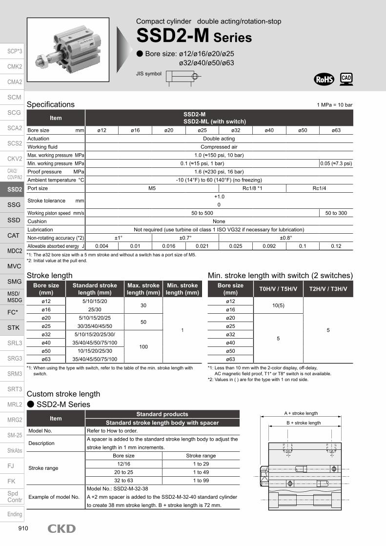
Compact cylinder double acting/rotation-stop
SSD2-M Series Bore size: ø12/ø16/ø20/ø25
ø32/ø40/ø50/ø63
Specifications
*1: The ø32 bore size with a 5 mm stroke and without a switch has a port size of M5.*2: Initial value at the pull end.
Item SSD2-MSSD2-ML (with switch)
Bore size mm ø12 ø16 ø20 ø25 ø32 ø40 ø50 ø63Actuation Double actingWorking fluid Compressed airMax. working pressure MPa 1.0 (≈150 psi, 10 bar)Min. working pressure MPa 0.1 (≈15 psi, 1 bar) 0.05 (≈7.3 psi)Proof pressure MPa 1.6 (≈230 psi, 16 bar)Ambient temperature °C -10 (14°F) to 60 (140°F) (no freezing)Port size M5 Rc1/8 *1 Rc1/4
Stroke tolerance mm+1.0
0Working piston speed mm/s 50 to 500 50 to 300Cushion NoneLubrication Not required (use turbine oil class 1 ISO VG32 if necessary for lubrication)Non-rotating accuracy (*2) ±1° ±0.7° ±0.8°Allowable absorbed energy J 0.004 0.01 0.016 0.021 0.025 0.092 0.1 0.12
Stroke length
*1: When using the type with switch, refer to the table of the min. stroke length with switch.
Bore size (mm)
Standard stroke length (mm)
Max. stroke length (mm)
Min. stroke length (mm)
ø12 5/10/15/2025/30
30
1
ø16ø20 5/10/15/20/25
30/35/40/45/5050
ø25ø32 5/10/15/20/25/30/
35/40/45/50/75/100100
ø40ø50 10/15/20/25/30
35/40/45/50/75/100ø63
Custom stroke length SSD2-M Series
ItemStandard products
Standard stroke length body with spacerModel No. Refer to How to order.
DescriptionA spacer is added to the standard stroke length body to adjust the stroke length in 1 mm increments.
Stroke range
Bore size Stroke range12/16 1 to 29
20 to 25 1 to 4932 to 63 1 to 99
Example of model No.Model No.: SSD2-M-32-38A +2 mm spacer is added to the SSD2-M-32-40 standard cylinder to create 38 mm stroke length. B + stroke length is 72 mm.
Min. stroke length with switch (2 switches)
*1: Less than 10 mm with the 2-color display, off-delay, AC magnetic field proof, T1* or T8* switch is not available.
*2: Values in ( ) are for the type with 1 on rod side.
Bore size(mm) T0H/V / T5H/V T2H/V / T3H/V
ø1210(5)
5
ø16ø20
5
ø25ø32ø40ø50ø63
JIS symbol
A + stroke length
B + stroke length
SCP*3
CMK2
CMA2
SCM
SCG
SCA2
SCS2
CKV2
CAV2/COVP/N2
SSD2
SSG
SSD
CAT
MDC2
MVC
SMG
MSD/MSDG
FC*
STK
SRL3
SRG3
SRM3
SRT3
MRL2
MRG2
SM‑25
ShkAbs
FJ
FK
SpdContr
Ending
910
1 MPa = 10 bar
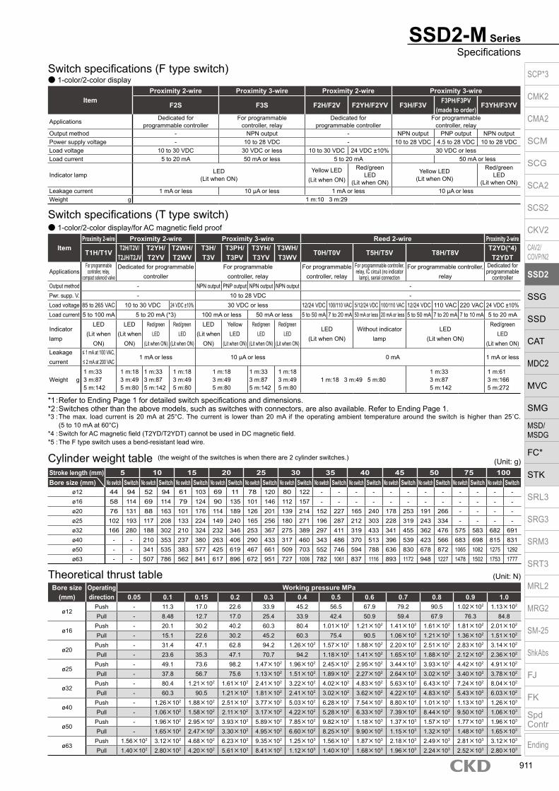
SSD2-M SeriesSpecifications
Switch specifications (F type switch) 1-color/2-color display
ItemProximity 2-wire Proximity 3-wire Proximity 2-wire Proximity 3-wire
F2S F3S F2H/F2V F2YH/F2YV F3H/F3VF3PH/F3PV
(made to order)F3YH/F3YV
Applications Dedicated for programmable controller
For programmable controller, relay
Dedicated for programmable controller
For programmable controller, relay
Output method - NPN output - NPN output PNP output NPN outputPower supply voltage - 10 to 28 VDC - 10 to 28 VDC 4.5 to 28 VDC 10 to 28 VDCLoad voltage 10 to 30 VDC 30 VDC or less 10 to 30 VDC 24 VDC ±10% 30 VDC or lessLoad current 5 to 20 mA 50 mA or less 5 to 20 mA 50 mA or less
Indicator lamp LED(Lit when ON)
Yellow LED(Lit when ON)
Red/greenLED
(Lit when ON)
Yellow LED(Lit when ON)
Red/greenLED
(Lit when ON)Leakage current 1 mA or less 10 μA or less 1 mA or less 10 μA or lessWeight g 1 m:10 3 m:29
Switch specifications (T type switch) 1-color/2-color display/for AC magnetic field proof
ItemProximity 2-wire Proximity 2-wire Proximity 3-wire Reed 2-wire Proximity 2-wire
T1H/T1VT2H/T2V/
T2JH/T2JVT2YH/T2YV
T2WH/T2WV
T3H/T3V
T3PH/T3PV
T3YH/T3YV
T3WH/T3WV
T0H/T0V T5H/T5V T8H/T8VT2YD(*4)T2YDT
ApplicationsFor programmable
controller, relay, compact solenoid valve
Dedicated for programmable controller
For programmable controller, relay
For programmable controller, relay
For programmable controller, relay, IC circuit (no indicator
lamp), serial connection
For programmable controller, relay
Dedicated for programmable
controllerOutput method - NPN output PNP output NPN output NPN output -Pwr. supp. V. - 10 to 28 VDC -Load voltage 85 to 265 VAC 10 to 30 VDC 24 VDC ±10% 30 VDC or less 12/24 VDC 100/110 VAC 5/12/24 VDC 100/110 VAC 12/24 VDC 110 VAC 220 VAC 24 VDC ±10%Load current 5 to 100 mA 5 to 20 mA (*3) 100 mA or less 50 mA or less 5 to 50 mA 7 to 20 mA 50 mA or less 20 mA or less 5 to 50 mA 7 to 20 mA 7 to 10 mA 5 to 20 mA
Indicator lamp
LED(Lit when
ON)
LED(Lit when
ON)
Red/green LED
(Lit when ON)
Red/green LED
(Lit when ON)
LED(Lit when
ON)
Yellow LED
(Lit when ON)
Red/green LED
(Lit when ON)
Red/green LED
(Lit when ON)
LED(Lit when ON)
Without indicator lamp
LED(Lit when ON)
Red/green LED
(Lit when ON)Leakage current
≤ 1 mA at 100 VAC, ≤ 2 mA at 200 VAC
1 mA or less 10 μA or less 0 mA 1 mA or less
Weight g1 m:333 m:875 m:142
1 m:183 m:495 m:80
1 m:333 m:875 m:142
1 m:183 m:495 m:80
1 m:183 m:495 m:80
1 m:333 m:875 m:142
1 m:183 m:495 m:80
1 m:18 3 m:49 5 m:801 m:333 m:875 m:142
1 m:613 m:1665 m:272
*1 : Refer to Ending Page 1 for detailed switch specifications and dimensions. *2 : Switches other than the above models, such as switches with connectors, are also available. Refer to Ending Page 1. *3 : The max. load current is 20 mA at 25°C. The current is lower than 20 mA if the operating ambient temperature around the switch is higher than 25˚C.
(5 to 10 mA at 60°C) *4 : Switch for AC magnetic field (T2YD/T2YDT) cannot be used in DC magnetic field. *5 : The F type switch uses a bend-resistant lead wire.
Theoretical thrust tableBore size
(mm)Operating direction
Working pressure MPa0.05 0.1 0.15 0.2 0.3 0.4 0.5 0.6 0.7 0.8 0.9 1.0
ø12Push - 11.3 17.0 22.6 33.9 45.2 56.5 67.9 79.2 90.5 1.02×10² 1.13×10²
Pull - 8.48 12.7 17.0 25.4 33.9 42.4 50.9 59.4 67.9 76.3 84.8
ø16Push - 20.1 30.2 40.2 60.3 80.4 1.01×10² 1.21×10² 1.41×10² 1.61×10² 1.81×10² 2.01×10²
Pull - 15.1 22.6 30.2 45.2 60.3 75.4 90.5 1.06×10² 1.21×10² 1.36×10² 1.51×10²
ø20Push - 31.4 47.1 62.8 94.2 1.26×10² 1.57×10² 1.88×10² 2.20×10² 2.51×10² 2.83×10² 3.14×10²
Pull - 23.6 35.3 47.1 70.7 94.2 1.18×10² 1.41×10² 1.65×10² 1.88×10² 2.12×10² 2.36×10²
ø25Push - 49.1 73.6 98.2 1.47×10² 1.96×10² 2.45×10² 2.95×10² 3.44×10² 3.93×10² 4.42×10² 4.91×10²
Pull - 37.8 56.7 75.6 1.13×10² 1.51×10² 1.89×10² 2.27×10² 2.64×10² 3.02×10² 3.40×10² 3.78×10²
ø32Push - 80.4 1.21×10² 1.61×10² 2.41×10² 3.22×10² 4.02×10² 4.83×10² 5.63×10² 6.43×10² 7.24×10² 8.04×10²
Pull - 60.3 90.5 1.21×10² 1.81×10² 2.41×10² 3.02×10² 3.62×10² 4.22×10² 4.83×10² 5.43×10² 6.03×10²
ø40Push - 1.26×10² 1.88×10² 2.51×10² 3.77×10² 5.03×10² 6.28×10² 7.54×10² 8.80×10² 1.01×10³ 1.13×10³ 1.26×10³
Pull - 1.06×10² 1.58×10² 2.11×10² 3.17×10² 4.22×10² 5.28×10² 6.33×10² 7.39×10² 8.44×10² 9.50×10² 1.06×10³
ø50Push - 1.96×10² 2.95×10² 3.93×10² 5.89×10² 7.85×10² 9.82×10² 1.18×10³ 1.37×10³ 1.57×10³ 1.77×10³ 1.96×10³
Pull - 1.65×10² 2.47×10² 3.30×10² 4.95×10² 6.60×10² 8.25×10² 9.90×10² 1.15×10³ 1.32×10³ 1.48×10³ 1.65×10³
ø63Push 1.56×10² 3.12×10² 4.68×10² 6.23×10² 9.35×10² 1.25×10³ 1.56×10³ 1.87×10³ 2.18×10³ 2.49×10³ 2.81×10³ 3.12×10³
Pull 1.40×10² 2.80×10² 4.20×10² 5.61×10² 8.41×10² 1.12×10³ 1.40×10³ 1.68×10³ 1.96×10³ 2.24×10³ 2.52×10³ 2.80×10³
(Unit: N)
Stroke length (mm) 5 10 15 20 25 30 35 40 45 50 75 100Bore size (mm) No switch Switch No switch Switch No switch Switch No switch Switch No switch Switch No switch Switch No switch Switch No switch Switch No switch Switch No switch Switch No switch Switch No switch Switch
ø12 44 94 52 94 61 103 69 11 78 120 80 122 - - - - - - - - - - - -ø16 58 114 69 114 79 124 90 135 101 146 112 157 - - - - - - - - - - - -ø20 76 131 88 163 101 176 114 189 126 201 139 214 152 227 165 240 178 253 191 266 - - - -ø25 102 193 117 208 133 224 149 240 165 256 180 271 196 287 212 303 228 319 243 334 - - - -ø32 166 280 188 302 210 324 232 346 253 367 275 389 297 411 319 433 341 455 362 476 575 583 682 691ø40 - - 210 353 237 380 263 406 290 433 317 460 343 486 370 513 396 539 423 566 683 698 815 831ø50 - - 341 535 383 577 425 619 467 661 509 703 552 746 594 788 636 830 678 872 1065 1082 1275 1292ø63 - - 507 786 562 841 617 896 672 951 727 1006 782 1061 837 1116 893 1172 948 1227 1478 1502 1753 1777
Cylinder weight table (the weight of the switches is when there are 2 cylinder switches.) (Unit: g)
SCP*3
CMK2
CMA2
SCM
SCG
SCA2
SCS2
CKV2
CAV2/COVP/N2
SSD2
SSG
SSD
CAT
MDC2
MVC
SMG
MSD/MSDG
FC*
STK
SRL3
SRG3
SRM3
SRT3
MRL2
MRG2
SM‑25
ShkAbs
FJ
FK
SpdContr
Ending
911
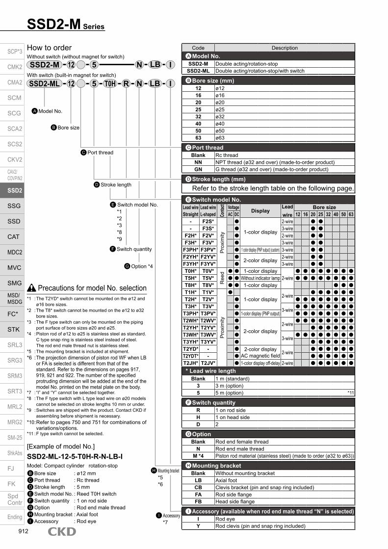
SSD2-M Series
Model No.A
Accessory *7
I
How to orderWithout switch (without magnet for switch)
With switch (built-in magnet for switch)
12 IN5
*1*2*3*8*9
E Switch model No.
Bore sizeB
Stroke lengthD
5
Port threadC
12 R IN
Option *4G
Switch quantityF
Code DescriptionModel No.
SSD2-M Double acting/rotation-stopSSD2-ML Double acting/rotation-stop/with switch
Bore size (mm)12 ø1216 ø1620 ø2025 ø2532 ø3240 ø4050 ø5063 ø63
Port threadBlank Rc thread
NN NPT thread (ø32 and over) (made-to-order product)GN G thread (ø32 and over) (made-to-order product)
Stroke length (mm)Refer to the stroke length table on the following page.
* Lead wire lengthBlank 1 m (standard)
3 3 m (option)5 5 m (option) *11
Switch quantityR 1 on rod sideH 1 on head sideD 2
OptionBlank Rod end female thread
N Rod end male threadM *4 Piston rod material (stainless steel) (made to order (ø32 to ø63))
Mounting bracketBlank Without mounting bracket
LB Axial footCB Clevis bracket (pin and snap ring included)FA Rod side flangeFB Head side flange
Accessory (available when rod end male thread “N” is selected)I Rod eyeY Rod clevis (pin and snap ring included)
A
B
C
F
G
I
H
Switch model No.Lead wire Lead wire
Conta
ct Voltage DisplayLead wire
Bore sizeStraight L-shaped AC DC 12 16 20 25 32 40 50 63
- F2S*P
roxi
mity
1-color display
2-wire - F3S* 3-wire
F2H* F2V* 2-wire F3H* F3V* 3-wire
F3PH* F3PV* 1 color display (PNP output) (custom) 3-wire F2YH* F2YV*
2-color display2-wire
F3YH* F3YV* 3-wire T0H* T0V*
Ree
d 1-color display2-wire
T5H* T5V* Without indicator lamp T8H* T8V* 1-color display T1H* T1V*
Pro
xim
ity
1-color display
2-wire
T2H* T2V* T3H* T3V*
3-wire
T3PH* T3PV* 1-color display (PNP output) T2WH* T2WV*
2-color display2-wire
T2YH* T2YV* T3WH* T3WV*
3-wire
T3YH* T3YV* T2YD* - 2-color display
AC magnetic field 2-wire
T2YDT* - T2JH* T2JV* 1-color display off-delay 2-wire
D
E
Precautions for model No. selection*1 : The T2YD* switch cannot be mounted on the ø12 and
ø16 bore sizes.*2 : The T8* switch cannot be mounted on the ø12 to ø32
bore sizes.*3 : The F type switch can only be mounted on the piping
port surface of bore sizes ø20 and ø25.*4 : Piston rod of ø12 to ø25 is stainless steel as standard.
C type snap ring is stainless steel instead of steel. The rod end male thread nut is stainless steel.*5 : The mounting bracket is included at shipment.*6 : The projection dimension of piston rod WF when LB
or FA is selected is different from that of the standard. Refer to the dimensions on pages 917, 919, 921 and 922. The number of the specified protruding dimension will be added at the end of the model No. printed on the metal plate on the body.
*7 : “I” and “Y” cannot be selected together.*8 : The F type switch with L type lead wire on ø20 models
cannot be selected on stroke lengths 10 mm or under.*9 : Switches are shipped with the product. Contact CKD if
assembling before shipment is necessary.*10 : Refer to pages 750 and 751 for combinations of
variations/options.*11 : F type switch cannot be selected.
[Example of model No.]SSD2-ML-12-5-T0H-R-N-LB-IModel: Compact cylinder rotation-stopB Bore size : ø12 mmC Port thread : Rc threadD Stroke length : 5 mmE Switch model No. : Reed T0H switchF Switch quantity : 1 on rod sideG Option : Rod end male threadH Mounting bracket : Axial footI Accessory : Rod eye
SSD2-M
SSD2-ML T0H LB
LB
Mounting bracket *5*6
H
SCP*3
CMK2
CMA2
SCM
SCG
SCA2
SCS2
CKV2
CAV2/COVP/N2
SSD2
SSG
SSD
CAT
MDC2
MVC
SMG
MSD/MSDG
FC*
STK
SRL3
SRG3
SRM3
SRT3
MRL2
MRG2
SM‑25
ShkAbs
FJ
FK
SpdContr
Ending
912
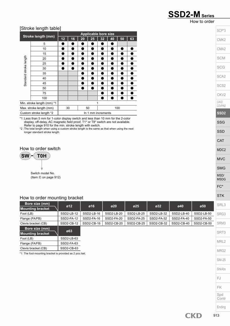
SSD2-M SeriesHow to order
Stroke length (mm)Applicable bore size
12 16 20 25 32 40 50 63
Sta
ndar
d st
roke
leng
th
5 10 15 20 25 30 35 40 45 50 75 100
Min. stroke length (mm) *1 1Max. stroke length (mm) 30 50 100Custom stroke length *2 In 1 mm increments
*1 : Less than 5 mm for 1-color display switch and less than 10 mm for the 2-color display, off-delay, AC magnetic field proof, T1* or T8* switch are not available.
Refer to page 910 for the min. stroke length with switch.*2 : The total length when using a custom stroke length is the same as that when using the next
longer standard stroke length.
[Stroke length table]
Bore size (mm)ø12 ø16 ø20 ø25 ø32 ø40 ø50
Mounting bracketFoot (LB) SSD2-LB-12 SSD2-LB-16 SSD2-LB-20 SSD2-LB-25 SSD2-LB-32 SSD2-LB-40 SSD2-LB-50Flange (FA/FB) SSD2-FA-12 SSD2-FA-16 SSD2-FA-20 SSD2-FA-25 SSD2-FA-32 SSD2-FA-40 SSD2-FA-50Clevis bracket (CB) SSD2-CB-12 SSD2-CB-16 SSD2-CB-20 SSD2-CB-25 SSD2-CB-32 SSD2-CB-40 SSD2-CB-50
Bore size (mm)ø63
Mounting bracketFoot (LB) SSD2-LB-63Flange (FA/FB) SSD2-FA-63Clevis bracket (CB) SSD2-CB-63*1: The foot mounting bracket is provided as 2 pcs./set.
How to order mounting bracket
How to order switch
Switch model No. (Item E on page 912)
SW T0H
SCP*3
CMK2
CMA2
SCM
SCG
SCA2
SCS2
CKV2
CAV2/COVP/N2
SSD2
SSG
SSD
CAT
MDC2
MVC
SMG
MSD/MSDG
FC*
STK
SRL3
SRG3
SRM3
SRT3
MRL2
MRG2
SM‑25
ShkAbs
FJ
FK
SpdContr
Ending
913

SSD2-M Series
Internal structure and parts list (ø12 to ø25) SSD2-ML-12 to 25 (double acting/rotation-stop/with switch)
SSD2-M-12 to 25 (double acting/rotation-stop)
No. Part name Material Remarks No. Part name Material Remarks1 Piston rod Stainless steel 8 Magnet Plastic
2 C type snap ring Steel Zinc phosphate 9 Piston Aluminum alloy Chromate
3 Rod metal Special aluminum Alumite 10 Piston packing Nitrile rubber
4 Rod metal gasket Nitrile rubber 11 Cover Stainless steel
5 Body Aluminum alloy Hard alumite 13 Hexagon socket set screw Steel
6 Rod packing Nitrile rubber
7 Spacer Aluminum alloy Chromate
Bore size (mm) Kit No. Repair parts No.ø12 SSD2-M-12K
4 6 10ø16 SSD2-M-16Kø20 SSD2-M-20Kø25 SSD2-M-25K
Repair parts list
1 2 6 4 3 109 1113 5
1 2 3 6 4 5 111013 97 8
SCP*3
CMK2
CMA2
SCM
SCG
SCA2
SCS2
CKV2
CAV2/COVP/N2
SSD2
SSG
SSD
CAT
MDC2
MVC
SMG
MSD/MSDG
FC*
STK
SRL3
SRG3
SRM3
SRT3
MRL2
MRG2
SM‑25
ShkAbs
FJ
FK
SpdContr
Ending
914

SSD2-M-32 to 63 (double acting/rotation-stop)
SSD2-M SeriesInternal structure and parts list
Internal structure and parts list (ø32 to ø63) SSD2-ML-32 to 63 (double acting/rotation-stop/with switch)
No. Part name Material Remarks No. Part name Material Remarks1 Piston rod Steel Industrial chrome plating 8 Magnet Plastic
2 C type snap ring Steel Zinc phosphate9 Piston Aluminum alloy Chromate
3 Rod metal ø32 to ø50: Special aluminumø63: Aluminum alloy Alumite
10 Piston packing Nitrile rubber
4 Rod metal gasket Nitrile rubber 11 Cover Aluminum alloy Alumite
5 Body Aluminum alloy Hard alumite 12 Bush Oil impregnated bearing alloy
6 Rod packing Nitrile rubber 13 Hexagon socket set screw Steel
7 Spacer Aluminum alloy Chromate
Bore size (mm) Kit No. Repair parts No.ø32 SSD2-M-32K
4 6 10ø40 SSD2-M-40Kø50 SSD2-M-50Kø63 SSD2-M-63K
Repair parts list
1213
1 3 2 6 4 5 9 1110
1 3 2 5 1146 107 98
13 12
SCP*3
CMK2
CMA2
SCM
SCG
SCA2
SCS2
CKV2
CAV2/COVP/N2
SSD2
SSG
SSD
CAT
MDC2
MVC
SMG
MSD/MSDG
FC*
STK
SRL3
SRG3
SRM3
SRT3
MRL2
MRG2
SM‑25
ShkAbs
FJ
FK
SpdContr
Ending
915

SSD2-M Series
Dimensions SSD2-ML-12 to 25 (with switch) Rod end male thread
ø12/ø16
ø20/ø25
Codea’ c’ H kk’ M MM T wf
Bore size (mm)ø12 10.5 9 8 M5 5 6 3.2 3.5ø16 12 10 10 M6 6 8 3.6 3.5ø20 14 12 13 M8 8 10 5 4.5ø25 17.5 15 17 M10×1.25 10 12 6 5
Dimensions of rod end male thread part
*1 : To calculate A+ stroke length or B+ stroke length when using custom stroke length, apply the next longer standard stroke length (instead of the custom stroke length) to the stroke length value.
(Example) If the custom stroke length is 7 mm, apply the standard stroke length of 10 mm.*2 : HD and RD dimensions for 5 mm stroke length differ from these dimensions according to the setting.*3 : Refer to page 1044 for HD, RD and protruding dimensions of the 2-color display, off-delay, AC magnetic field proof, T1* and T8* switches.*4 : Dimensions in ( ) of FA are for the radial lead wire.*5 : For dimensions of individual accessories, refer to pages 1046 to 1049.*6 : Only F type switch is available for the ø20 or ø25 piping port surface.
Code Common dimensions with switchBore size (mm) A *1 B *1 C D EE F FA *4 FB I J K KA KK M MM N WF
ø12 30.5 27 10.5 5.5 M5 25 13(16.5) 4.5 3.5 6.5 spot face depth 3.5 32 M4 depth 7 M3 depth 6 5 6 15.5 3.5ø16 30.5 27 10.5 5.5 M5 29 15(18.5) 4.5 3.5 6.5 spot face depth 3.5 38 M4 depth 7 M4 depth 8 6 8 20 3.5ø20 39 34.5 13 5.5 M5 36 18.5(22) 12.5 5.5 9 spot face depth 5.5 47 M6 depth 11 M5 depth 7 8 10 25.5 4.5ø25 42.5 37.5 16 6 M5 40 20.5(24) 13.5 5.5 9 spot face depth 5.5 51 M6 depth 11 M6 depth 12 10 12 28 5
Switch dimensions
Reed T0H/T0V, T5H/T5V
Proximity T2H/T2V, T3H/T3V
Proximity T2WH/T2WV, T3WH/T3WV
Proximity F2H/F2V, F3H/F3V, F2YH/F2YV, F3YH/F3YV
Proximity F2S/F3S
Bore size (mm) HD RD HD RD HD RD HD RD HD RDø12 0 7.5 0 7.5 2 9.5ø16 0 7 0 7 2.5 9.5ø20 3 11.5 3 11.5 5 13 7.5 15.5 6.5 14.5ø25 3 14.5 3 14.5 6 16 8.5 18.5 7.5 17.5
a’c’
T
wf
kk’Width across flats M
Width across flats H
øMM
F8-J
8-J
Mounting holeN
øK
F N
FBM
FA
FB FA
øMM
WF
KK
C D 2-EE
KAøI
B + stroke length
*4
*4
A + stroke length
F
Mounting holeN
øK
F N
M
FB øMM
WF
KK
C D 2-EE
8-KAøI
B + stroke length
FA*4
A + stroke length
RD
HD
HD
RD
SCP*3
CMK2
CMA2
SCM
SCG
SCA2
SCS2
CKV2
CAV2/COVP/N2
SSD2
SSG
SSD
CAT
MDC2
MVC
SMG
MSD/MSDG
FC*
STK
SRL3
SRG3
SRM3
SRT3
MRL2
MRG2
SM‑25
ShkAbs
FJ
FK
SpdContr
Ending
916

SSD2-M SeriesDouble acting/rotation-stop
Dimensions with mounting bracket Axial foot (LB) with switch Clevis bracket (CB) with switch SSD2-ML-12 to 25 -LB SSD2-MY-12 to 25 -CB
Rod side flange (FA) with switch SSD2-ML-12 to 25 -FA
Head side flange (FB) with switch SSD2-ML-12 to 25 -FB
Code Common dimensionsBore size
(mm) CA CB CC CD D E G H N UB
ø12 12 5.2 7 5 4 25 M4×12 C1.5 15.5 10ø16 15 6.6 8 5 5 29 M4×12 C2 20 12ø20 20 8.2 12 8 5 36 M6×16 C4 25.5 16ø25 24 10.2 14 10 5 40 M6×16 C5 28 20
Code Female thread Male threadBore size
(mm) WF A B CJ a’ wf A B CJ
ø12 3.5 50.5 27 44.5 10.5 8.5 61 27 44.5ø16 3.5 51.5 27 45.5 12 8.5 63.5 27 45.5ø20 4.5 66 34.5 57 14 9.5 80 34.5 57ø25 5 72.5 37.5 62.5 17.5 10 90 37.5 62.5
+ 0.3 0
+ 0.2 0
+ 0.2 0
+ 0.2 0
-0.1-0.4
-0.1-0.3
-0.1-0.3
-0.1-0.3
Code Male threadBore size
(mm) WF LF A B LX a’ WF LF A B LX
ø12 13.5 19.5 45.3 27 15 10.5 13.5 19.5 55.8 27 15ø16 13.5 19.5 45.3 27 15 12 13.5 19.5 57.3 27 15ø20 14.5 20.5 56.2 34.5 22.5 14 14.5 20.5 70.2 34.5 22.5ø25 15 22.5 59.7 37.5 22.5 17.5 15 22.5 77.2 37.5 22.5
Code Common dimensions Female threadBore size
(mm) AB AG AH AK AT AU G N TR TS M
ø12 5 29.5 17 12.5 2 8 M4×10 15.5 34 44 4.8ø16 5 33.5 19 13 2 8 M4×10 20 38 48 4.8ø20 7 42 24 15 3.2 9.2 M6×16 25.5 48 62 7.2ø25 7 46 26 16.5 3.2 10.7 M6×16 28 52 66 7.2
Code Common dimensionsBore size
(mm) FD FH FL FM FT N Gø12 4.5 25 45 55 5.5 15.5 M4×12ø16 4.5 30 45 55 5.5 20 M4×12ø20 6.6 39 48 60 8 25.5 M6×16ø25 6.6 42 52 64 8 28 M6×16
Code Female thread Male threadBore size
(mm) WF A B a’ wf A Bø12 13.5 40.5 27 10.5 13.5 51 27ø16 13.5 40.5 27 12 13.5 52.5 27ø20 14.5 49 34.5 14 14.5 63 34.5ø25 15 52.5 37.5 17.5 15 70 37.5
Code Common dimensionsBore size
(mm) FD FH FL FM FT N Gø12 4.5 25 45 55 5.5 15.5 M4×12ø16 4.5 30 45 55 5.5 20 M4×12ø20 6.6 39 48 60 8 25.5 M6×16ø25 6.6 42 52 64 8 28 M6×16
Code Female thread Male threadBore size
(mm) WF A B a’ wf A Bø12 3.5 36 27 10.5 8.5 46.5 27ø16 3.5 36 27 12 8.5 48 27ø20 4.5 47 34.5 14 9.5 61 34.5ø25 5 50.5 37.5 17.5 10 68 37.5
N
AG N
TRTS
AT
AH
4-øAB
WFA + stroke length
B + stroke length M
AUAK
Low head hexagon socket bolt 8-G
LX + stroke lengthLF
A + stroke lengthB + stroke lengtha’ wf
LF
Rod end male thread
N
FM
FH
WF
Mounting bolt 4-GHexagon socket button head bolt
A + stroke lengthB + stroke lengtha’ wf FT
FL
Rod end male thread
A + stroke length
B + stroke length FT N
2-FD
N
WF
A + stroke lengthB + stroke lengtha’ wf
Rod end male thread
A + stroke lengthB + stroke length
H
CJ + stroke lengthMounting bolt 4-C
N
E
E
CBCC
UBD
øCA
CD H10
CJ + stroke length
A + stroke lengthB + stroke length
FM
NFH
N
2-FD
Mounting bolt 4-GHexagon socket button head bolt
Rod end male thread
FT
A + stroke lengthB + stroke length
FTa’ wf
WFFL
SCP*3
CMK2
CMA2
SCM
SCG
SCA2
SCS2
CKV2
CAV2/COVP/N2
SSD2
SSG
SSD
CAT
MDC2
MVC
SMG
MSD/MSDG
FC*
STK
SRL3
SRG3
SRM3
SRT3
MRL2
MRG2
SM‑25
ShkAbs
FJ
FK
SpdContr
Ending
917

Dimensions SSD2-M-12 to 25 (without switch) Rod end male thread
ø12/ø16
ø20/ø25
Codea’ c’ H kk’ M MM T wf
Bore size (mm)ø12 10.5 9 8 M5 5 6 3.2 3.5
ø16 12 10 10 M6 6 8 3.6 3.5
ø20 14 12 13 M8 8 10 5 4.5
ø25 17.5 15 17 M10×1.25 10 12 6 5
Dimensions of rod end male thread part
Code Without switchBore size (mm) A *1 B *1 C D EE F I J K KA KK M MM N WF
ø12 25.5 22 10.5 5.5 M5 25 3.5 6.5 spot face depth 3.5 32 M4 depth 7 M3 depth 6 5 6 15.5 3.5
ø16 25.5 22 10.5 5.5 M5 29 3.5 6.5 spot face depth 3.5 38 M4 depth 7 M4 depth 8 6 8 20 3.5
ø20 29 24.5 13 5.5 M5 36 5.5 9 spot face depth 5.5 47 M6 depth 11 M5 depth 7 8 10 25.5 4.5
ø25 32.5 27.5 16 6 M5 40 5.5 9 spot face depth 5.5 51 M6 depth 11 M6 depth 12 10 12 28 5
*1 : To calculate A+ stroke length or B+ stroke length when using custom stroke length, apply the next longer standard stroke length (instead of the custom stroke length) to the stroke length value.
(Example) If the custom stroke length is 7 mm, apply the standard stroke length of 10 mm.*2 : For dimensions of individual accessories, refer to pages 1046 to 1049.
SSD2-M Series
a’c’
T
wf
kk’Width across flats M
Width across flats H
øMM
F8-J
Mounting holeN
øK
F N
M
øMM
WF
KK
C D 2-EE
8-KAøI
B + stroke lengthA + stroke length
F
8-JMounting hole
N
øK
F N
M
øMM
WF
KK
C D 2-EE
8-KAøI
B + stroke length
A + stroke length
SCP*3
CMK2
CMA2
SCM
SCG
SCA2
SCS2
CKV2
CAV2/COVP/N2
SSD2
SSG
SSD
CAT
MDC2
MVC
SMG
MSD/MSDG
FC*
STK
SRL3
SRG3
SRM3
SRT3
MRL2
MRG2
SM‑25
ShkAbs
FJ
FK
SpdContr
Ending
918
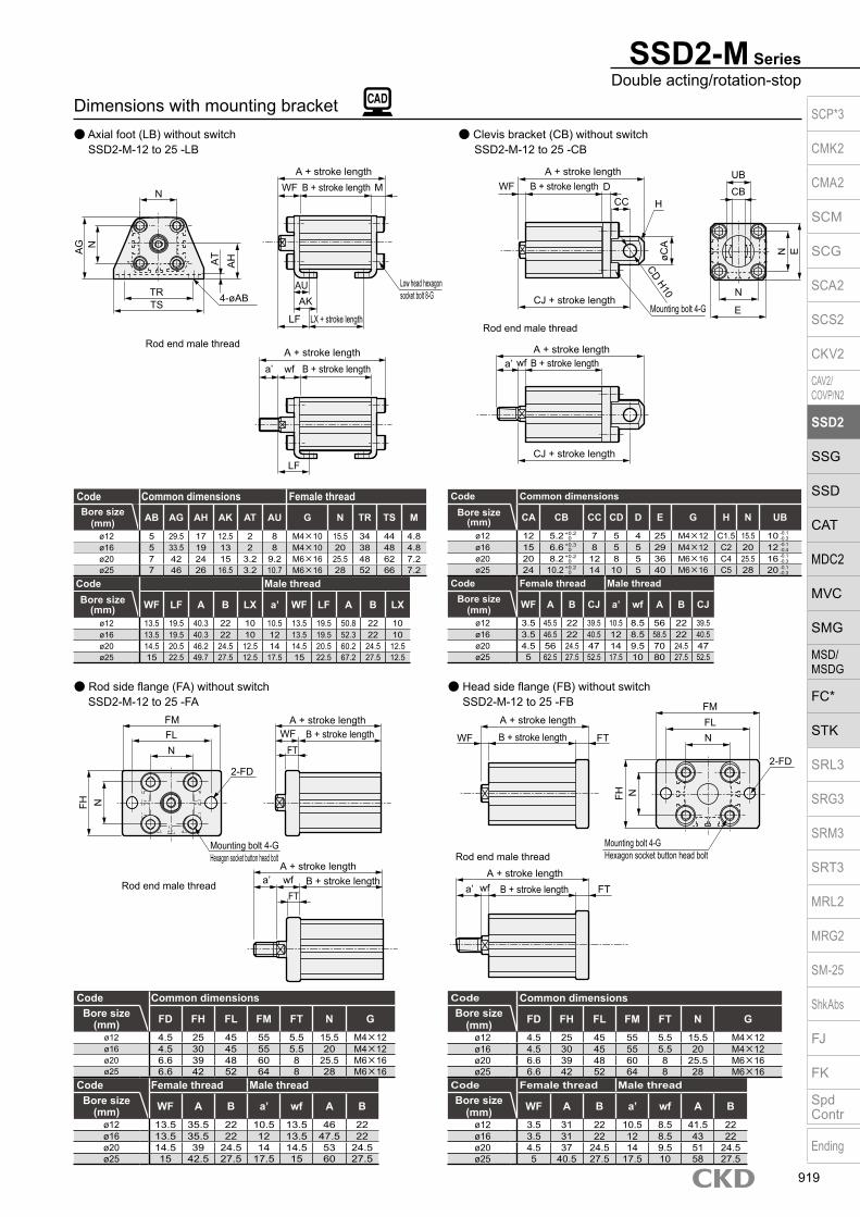
SSD2-M SeriesDouble acting/rotation-stop
Dimensions with mounting bracket Axial foot (LB) without switch Clevis bracket (CB) without switch
SSD2-M-12 to 25 -LB SSD2-M-12 to 25 -CB
Rod side flange (FA) without switchSSD2-M-12 to 25 -FA
Head side flange (FB) without switch SSD2-M-12 to 25 -FB
Code Common dimensionsBore size
(mm) CA CB CC CD D E G H N UB
ø12 12 5.2 7 5 4 25 M4×12 C1.5 15.5 10ø16 15 6.6 8 5 5 29 M4×12 C2 20 12ø20 20 8.2 12 8 5 36 M6×16 C4 25.5 16ø25 24 10.2 14 10 5 40 M6×16 C5 28 20
Code Female thread Male threadBore size
(mm) WF A B CJ a’ wf A B CJ
ø12 3.5 45.5 22 39.5 10.5 8.5 56 22 39.5ø16 3.5 46.5 22 40.5 12 8.5 58.5 22 40.5ø20 4.5 56 24.5 47 14 9.5 70 24.5 47ø25 5 62.5 27.5 52.5 17.5 10 80 27.5 52.5
+ 0.3 0
+ 0.2 0
+ 0.2 0
+ 0.2 0
-0.1-0.4
-0.1-0.3
-0.1-0.3
-0.1-0.3
Code Common dimensionsBore size
(mm) FD FH FL FM FT N Gø12 4.5 25 45 55 5.5 15.5 M4×12ø16 4.5 30 45 55 5.5 20 M4×12ø20 6.6 39 48 60 8 25.5 M6×16ø25 6.6 42 52 64 8 28 M6×16
Code Female thread Male threadBore size
(mm) WF A B a’ wf A Bø12 3.5 31 22 10.5 8.5 41.5 22ø16 3.5 31 22 12 8.5 43 22ø20 4.5 37 24.5 14 9.5 51 24.5ø25 5 40.5 27.5 17.5 10 58 27.5
Code Male threadBore size
(mm) WF LF A B LX a’ WF LF A B LX
ø12 13.5 19.5 40.3 22 10 10.5 13.5 19.5 50.8 22 10ø16 13.5 19.5 40.3 22 10 12 13.5 19.5 52.3 22 10ø20 14.5 20.5 46.2 24.5 12.5 14 14.5 20.5 60.2 24.5 12.5ø25 15 22.5 49.7 27.5 12.5 17.5 15 22.5 67.2 27.5 12.5
Code Common dimensions Female threadBore size
(mm) AB AG AH AK AT AU G N TR TS M
ø12 5 29.5 17 12.5 2 8 M4×10 15.5 34 44 4.8ø16 5 33.5 19 13 2 8 M4×10 20 38 48 4.8ø20 7 42 24 15 3.2 9.2 M6×16 25.5 48 62 7.2ø25 7 46 26 16.5 3.2 10.7 M6×16 28 52 66 7.2
Code Common dimensionsBore size
(mm) FD FH FL FM FT N Gø12 4.5 25 45 55 5.5 15.5 M4×12ø16 4.5 30 45 55 5.5 20 M4×12ø20 6.6 39 48 60 8 25.5 M6×16ø25 6.6 42 52 64 8 28 M6×16
Code Female thread Male threadBore size
(mm) WF A B a’ wf A Bø12 13.5 35.5 22 10.5 13.5 46 22ø16 13.5 35.5 22 12 13.5 47.5 22ø20 14.5 39 24.5 14 14.5 53 24.5ø25 15 42.5 27.5 17.5 15 60 27.5
N
AG N
TRTS
AT
AH
4-øAB
WFA + stroke length
B + stroke length M
AUAK
Low head hexagon socket bolt 8-G
LX + stroke lengthLF
A + stroke lengthB + stroke lengtha’ wf
LF
Rod end male thread
N
FM
FH
WF
Mounting bolt 4-GHexagon socket button head bolt
A + stroke lengthB + stroke lengtha’ wf FT
FL
Rod end male thread
A + stroke length
B + stroke length FT N
2-FD
N
WF
A + stroke lengthB + stroke lengtha’ wf
Rod end male thread
A + stroke lengthB + stroke length
H
CJ + stroke lengthMounting bolt 4-G
N
E
E
CBCC
UBD
øCA
CD H10
CJ + stroke length
A + stroke lengthB + stroke length
FM
NFH
N
2-FD
Mounting bolt 4-GHexagon socket button head bolt
Rod end male thread
FT
A + stroke lengthB + stroke length
FTa’ wf
WFFL
SCP*3
CMK2
CMA2
SCM
SCG
SCA2
SCS2
CKV2
CAV2/COVP/N2
SSD2
SSG
SSD
CAT
MDC2
MVC
SMG
MSD/MSDG
FC*
STK
SRL3
SRG3
SRM3
SRT3
MRL2
MRG2
SM‑25
ShkAbs
FJ
FK
SpdContr
Ending
919

SSD2-M Series
Dimensions SSD2-ML-32 to 63 (with switch) Rod end male thread
SSD2-M-32 to 63 (without switch)
Codea’ c’ H kk’ M MM T wf
Bore size (mm)ø32 23.5 20.5 22 M14×1.5 14 16 8 5
ø40 23.5 20.5 22 M14×1.5 14 16 8 5
ø50 28.5 26 27 M18×1.5 18 20 11 5
ø63 28.5 26 27 M18×1.5 18 20 11 5
Rod end male thread
*1 : To calculate A+ stroke length or B+ stroke length when using custom stroke length, apply the next longer standard stroke length (instead of the custom stroke length) to the stroke length value. (Example) If the custom stroke length is 7 mm, apply the standard stroke length of 10 mm.
*2 : HD and RD dimensions for 5 mm stroke length differ from these dimensions according to the setting.*3 : Refer to page 1044 for HD, RD and protruding dimensions of the 2-color display, off-delay, AC magnetic field proof, T1* and T8* switches.*4 : Dimensions in ( ) of FA are for the radial lead wire.*5 : For dimensions of individual accessories, refer to pages 1046 to 1049.*6 : Dimensions in ( ) of codes A and B are for stroke lengths of more than 50 mm.*7 : The ø32 bore size with a 5 mm stroke and without a switch has a port size of M5.*8 : Dimensions in ( ) of codes C and D are when the value is for a 5 mm stroke without switch.
Code Without switch Common dimensions with switchBore size (mm) A *1/*6 B *1/*6 A *1 B *1 C *8 D *8 EE F FA *4 FB G H I J K KA
ø32 39(49) 32(42) 49 42 18(20) 8(5.5) Rc1/8 *7 45 23(26.5) 20.5 49.5 12.5 5.5 9 spot face depth 5.5 60 M6 depth 11
ø40 36.5(46.5) 29.5(39.5) 46.5 39.5 12(11.5) 8.5(8) Rc1/8 52 26.5(30) 27.5 57 15 5.5 9 spot face depth 5.5 69 M6 depth 11
ø50 38.5(48.5) 30.5(40.5) 48.5 40.5 10.5 10.5 Rc1/4 64 32.5(36) 28.5 71 18 6.9 11 spot face depth 6.5 86 M8 depth 13
ø63 44(54) 36(46) 54 46 13 11 Rc1/4 77 39(42.5) 28.5 84 23 8.7 14 spot face depth 9 103 M10 depth 25
Code Common dimensions with switch Reed T0H/T0V, T5H/T5V
Proximity T2H/T2V, T3H/T3V
Proximity T2WH/T2WV, T3WH/T3WV
Bore size (mm) KK M MM N O P V WF HD *2 RD *2 HD *2 RD *2 HD RDø32 M8 depth 13 14 16 34 4.5 21 2 7 4.5 19 4.5 19 5 20.5
ø40 M8 depth 13 14 16 40 5 28 2 7 7 12 7 12 8.5 13.5
ø50 M10 depth 15 18 20 50 7 35 2 8 7.5 12.5 7.5 12.5 9 14
ø63 M10 depth 15 18 20 60 7 35 2 8 12.5 13 12.5 13 14 14.5
a’
c’
T
wf
kk’
Width across flats M
Width across flats H
øMM
F
8-JMounting hole
N
øK
F N
M
FB øP h
9
WF
C D 2-EE
8-KAøI
B + stroke length
FA*4
KKHD
H
O
G
RD
F
8-JMounting hole
N
øK
F N
M
øMM
WF
KK
C D 2-EE
8-KAøIB + stroke length
H
O
G
A + stroke length
V
øMM
FB
øP h
9
A + stroke length
V
V
SCP*3
CMK2
CMA2
SCM
SCG
SCA2
SCS2
CKV2
CAV2/COVP/N2
SSD2
SSG
SSD
CAT
MDC2
MVC
SMG
MSD/MSDG
FC*
STK
SRL3
SRG3
SRM3
SRT3
MRL2
MRG2
SM‑25
ShkAbs
FJ
FK
SpdContr
Ending
920
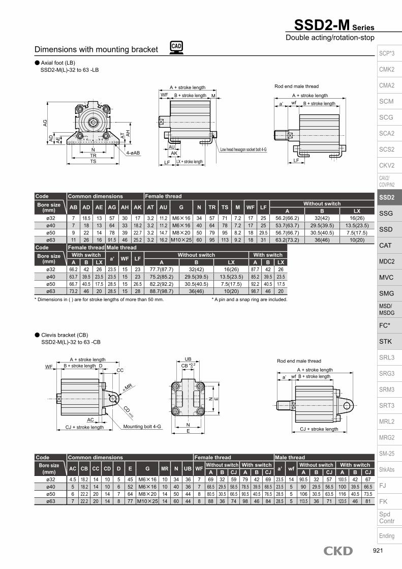
Dimensions with mounting bracket Axial foot (LB) SSD2-M(L)-32 to 63 -LB
Clevis bracket (CB) SSD2-M(L)-32 to 63 -CB
SSD2-M SeriesDouble acting/rotation-stop
Code Common dimensions Female threadBore size
(mm) AB AD AE AG AH AK AT AU G N TR TS M WF LFWithout switch
A B LXø32 7 18.5 13 57 30 17 3.2 11.2 M6×16 34 57 71 7.2 17 25 56.2(66.2) 32(42) 16(26)ø40 7 18 13 64 33 18.2 3.2 11.2 M6×16 40 64 78 7.2 17 25 53.7(63.7) 29.5(39.5) 13.5(23.5)ø50 9 22 14 78 39 22.7 3.2 14.7 M8×20 50 79 95 8.2 18 29.5 56.7(66.7) 30.5(40.5) 7.5(17.5)ø63 11 26 16 91.5 46 25.2 3.2 16.2 M10×25 60 95 113 9.2 18 31 63.2(73.2) 36(46) 10(20)
Code Female thread Male threadBore size
(mm)With switch
a’ WF LFWithout switch With switch
A B LX A B LX A B LXø32 66.2 42 26 23.5 15 23 77.7(87.7) 32(42) 16(26) 87.7 42 26ø40 63.7 39.5 23.5 23.5 15 23 75.2(85.2) 29.5(39.5) 13.5(23.5) 85.2 39.5 23.5ø50 66.7 40.5 17.5 28.5 15 26.5 82.2(92.2) 30.5(40.5) 7.5(17.5) 92.2 40.5 17.5ø63 73.2 46 20 28.5 15 28 88.7(98.7) 36(46) 10(20) 98.7 46 20
* A pin and a snap ring are included.* Dimensions in ( ) are for stroke lengths of more than 50 mm.
Code Common dimensions Female thread Male threadBore size
(mm) AC CB CC CD D E G MR N UB WFWithout switch With switch
a’ wfWithout switch With switch
A B CJ A B CJ A B CJ A B CJø32 4.5 18.2 14 10 5 45 M6×16 10 34 36 7 69 32 59 79 42 69 23.5 14 90.5 32 57 100.5 42 67ø40 5 18.2 14 10 6 52 M6×16 10 40 36 7 68.5 29.5 58.5 78.5 39.5 68.5 23.5 5 90 29.5 56.5 100 39.5 66.5ø50 6 22.2 20 14 7 64 M8×20 14 50 44 8 80.5 30.5 66.5 90.5 40.5 76.5 28.5 5 106 30.5 63.5 116 40.5 73.5ø63 7 22.2 20 14 8 77 M10×25 14 60 44 8 88 36 74 98 46 84 28.5 5 113.5 36 71 123.5 46 81
NTRTS
4-øAB
AD
AE A
T AH
LF
A + stroke length
Rod end male thread
B + stroke lengtha’ wf
LX + stroke length
A + stroke length
B + stroke length
Low head hexagon socket bolt 4-G
LF
WF
AUAK
M
AG
N
A + stroke length
Rod end male thread
B + stroke lengtha’ wf
A + stroke lengthB + stroke lengthWF
CJ + stroke lengthCJ + stroke length
CC
UBD
NE
E
CD H10
Mounting bolt 4-GAC
R MR
CB + 0.2 0
SCP*3
CMK2
CMA2
SCM
SCG
SCA2
SCS2
CKV2
CAV2/COVP/N2
SSD2
SSG
SSD
CAT
MDC2
MVC
SMG
MSD/MSDG
FC*
STK
SRL3
SRG3
SRM3
SRT3
MRL2
MRG2
SM‑25
ShkAbs
FJ
FK
SpdContr
Ending
921

SSD2-M Series
Head side flange (FB) SSD2-M(L)-32 to 63 -FB
Code Male threadBore size
(mm) a’ wfWithout switch With switchA B A B
ø32 23.5 15 70.5(80.5) 32(42) 80.5 42ø40 23.5 15 68(78) 29.5(39.5) 78 39.5ø50 28.5 15 74(84) 30.5(40.5) 84 40.5ø63 28.5 15 79.5(89.5) 36(46) 89.5 46
Code Common dimensions Female threadBore size
(mm) FC FD FH FL FM FT N G WFWithout switch With switchA B A B
ø32 34 5.5 48 56 65 8 34 M6×16 17 49(59) 32(42) 59 42ø40 40 5.5 54 62 72 8 40 M6×16 17 46.5(56.5) 29.5(39.5) 56.5 39.5ø50 50 6.6 67 76 89 9 50 M8×20 18 48.5(58.5) 30.5(40.5) 58.5 40.5ø63 60 9 80 92 108 9 60 M10×25 18 54(64) 36(46) 64 46
* Dimensions in ( ) are for stroke lengths of more than 50 mm.
Dimensions with mounting bracket Rod side flange (FA) SSD2-M(L)-32 to 63 -FA
Code Common dimensions Female thread Male threadBore size
(mm) FC FD FH FL FM FT N G WFWithout switch With switch
a’ wfWithout switch With switch
A B A B A B A Bø32 34 5.5 48 56 65 8 34 M6×16 7 47 32 57 42 23.5 14 68.5 32 78.5 42ø40 40 5.5 54 62 72 8 40 M6×16 7 44.5 29.5 54.5 39.5 23.5 5 66 29.5 76 39.5ø50 50 6.6 67 76 89 9 50 M8×20 8 47.5 30.5 57.5 40.5 28.5 5 73 30.5 83 40.5ø63 60 9 80 92 108 9 60 M10×25 8 53 36 63 46 28.5 5 78.5 36 88.5 46
Rod end male thread
A + stroke lengthB + stroke length
A + stroke lengthB + stroke lengtha’ wf
FTFT
FH FC
FM
NFL
4-FD
Mounting bolt 4-Gø32 to ø63: Hexagon socket
button head boltø80/ø100: Special bolt
WF
FH FC
A + stroke length
Rod end male thread
B + stroke lengtha’ wfA + stroke lengthB + stroke lengthWF FT4-FD
FLN
Mounting bolt 4-G
FM
FT
ø32 to ø63: Hexagon socket button head bolt
ø80/ø100: Special bolt
SCP*3
CMK2
CMA2
SCM
SCG
SCA2
SCS2
CKV2
CAV2/COVP/N2
SSD2
SSG
SSD
CAT
MDC2
MVC
SMG
MSD/MSDG
FC*
STK
SRL3
SRG3
SRM3
SRT3
MRL2
MRG2
SM‑25
ShkAbs
FJ
FK
SpdContr
Ending
922

M E M OM E M OSCP*3
CMK2
CMA2
SCM
SCG
SCA2
SCS2
CKV2
CAV2/COVP/N2
SSD2
SSG
SSD
CAT
MDC2
MVC
SMG
MSD/MSDG
FC*
STK
SRL3
SRG3
SRM3
SRT3
MRL2
MRG2
SM‑25
ShkAbs
FJ
FK
SpdContr
Ending
923

Compact cylinder double acting/double rod/rotation-stop
SSD2-DM Series Bore size: ø12/ø16/ø20/ø25 ø32/ø40/ø50/ø63
Specifications
*1: The ø32 bore size with a 5 mm stroke and without a switch has a port size of M5.*2: Initial value at the pull end.
Item SSD2-DMSSD2-DML (with switch)
Bore size mm ø12 ø16 ø20 ø25 ø32 ø40 ø50 ø63Actuation Double actingWorking fluid Compressed airMax. working pressure MPa 1.0 (≈150 psi, 10 bar)Min. working pressure MPa 0.15 (≈22 psi, 1.5 bar) 0.1 (≈15 psi)Proof pressure MPa 1.6 (≈230 psi, 16 bar)Ambient temperature °C -10 (14°F) to 60 (140°F) (no freezing)Port size M5 Rc1/8 *1 Rc1/4
Stroke tolerance mm+1.0
0Working piston speed mm/s 50 to 500 50 to 300Cushion NoneLubrication Not required (use turbine oil class 1 ISO VG32 if necessary for lubrication)Non-rotating accuracy (*2) ±1° ±0.7° ±0.8°Allowable absorbed energy J 0.004 0.01 0.016 0.021 0.025 0.092 0.1 0.12
Stroke length
*1: When using the type with switch, refer to the table of the min. stroke length with switch.
Bore size (mm) Standard stroke length (mm) Max. stroke length (mm) Min. stroke length (mm)ø12 5/10/15/20
25/3030
5
ø16ø20 5/10/15/20/25
30/35/40/45/5050
ø25ø32 5/10/15/20/25/30/
35/40/45/50/75/100100
ø40ø50 10/15/20/25/30
35/40/45/50/75/10010
ø63
Min. stroke length with switch (2 switches)
*1: Less than 10 mm with the 2-color display, off-delay, AC magnetic field proof, T1* or T8* switch is not available.
*2: Values in ( ) are for the type with 1 on rod side.
Bore size (mm) T0H/V / T5H/V T2H/V / T3H/Vø12
10(5)
5
ø16ø20
5ø25ø32ø40ø50
10 10ø63
JIS symbol
1 MPa = 10 bar
SCP*3
CMK2
CMA2
SCM
SCG
SCA2
SCS2
CKV2
CAV2/COVP/N2
SSD2
SSG
SSD
CAT
MDC2
MVC
SMG
MSD/MSDG
FC*
STK
SRL3
SRG3
SRM3
SRT3
MRL2
MRG2
SM‑25
ShkAbs
FJ
FK
SpdContr
Ending
924

SSD2-DM SeriesSpecifications
Switch specifications (F type switch) 1-color/2-color display
ItemProximity 2-wire Proximity 3-wire Proximity 2-wire Proximity 3-wire
F2S F3S F2H/F2VF2YH/F2YV
F3H/F3VF3PH/F3PV
(made to order)F3YH/F3YV
Applications Dedicated for programmable controller
For programmable controller, relay
Dedicated for programmable controller
For programmable controller, relay
Output method - NPN output - NPN output PNP output NPN outputPower supply voltage - 10 to 28 VDC - 10 to 28 VDC 4.5 to 28 VDC 10 to 28 VDCLoad voltage 10 to 30 VDC 30 VDC or less 10 to 30 VDC 24 VDC ±10% 30 VDC or lessLoad current 5 to 20 mA 50 mA or less 5 to 20 mA 50 mA or less
Indicator lamp LED(Lit when ON)
Yellow LED(Lit when ON)
Red/greenLED
(Lit when ON)
Yellow LED(Lit when ON)
Red/greenLED
(Lit when ON)Leakage current 1 mA or less 10 μA or less 1 mA or less 10 μA or lessWeight g 1 m:10 3 m:29
Switch specifications (T type switch) 1-color/2-color display/for AC magnetic field proof
ItemProximity 2-wire Proximity 2-wire Proximity 3-wire Reed 2-wire Proximity 2-wire
T1H/T1V T2H/T2V/T2JH/T2JV T2YH/T2YV T2WH/
T2WV T3H/T3V T3PH/T3PV T3YH/T3YV T3WH/
T3WV T0H/T0V T5H/T5V T8H/T8V T2YD(*4)T2YDT
ApplicationsFor programmable
controller, relay, compact solenoid valve
Dedicated for programmable controller
For programmable controller, relay
For programmable controller, relay
For programmable controller, relay, IC circuit (no indicator
lamp), serial connection
For programmable controller, relay
Dedicated for programmable
controllerOutput method - NPN output PNP output NPN output NPN output -Pwr. supp. V. - 10 to 28 VDC -Load voltage 85 to 265 VAC 10 to 30 VDC 24 VDC ±10% 30 VDC or less 12/24 VDC 100/110 VAC 5/12/24 VDC 100/110 VAC 12/24 VDC 110 VAC 220 VAC 24 VDC ±10%Load current 5 to 100 mA 5 to 20 mA (*3) 100 mA or less 50 mA or less 5 to 50 mA 7 to 20 mA 50 mA or less 20 mA or less 5 to 50 mA 7 to 20 mA 7 to 10 mA 5 to 20 mA
Indicator lamp
LED(Lit when
ON)
LED(Lit when
ON)
Red/green LED
(Lit when ON)
Red/green LED
(Lit when ON)
LED(Lit when
ON)
Yellow LED
(Lit when ON)
Red/green LED
(Lit when ON)
Red/green LED
(Lit when ON)
LED(Lit when ON)
Without indicator lamp
LED(Lit when ON)
Red/green LED
(Lit when ON)
Leakage current≤ 1 mA at 100 VAC, ≤ 2 mA at 200 VAC
1 mA or less 10 μA or less 0 mA 1 mA or less
Weight g1 m:333 m:875 m:142
1 m:183 m:495 m:80
1 m:333 m:875 m:142
1 m:183 m:495 m:80
1 m:183 m:495 m:80
1 m:333 m:875 m:142
1 m:183 m:495 m:80
1 m:18 3 m:49 5 m:801 m:333 m:875 m:142
1 m:613 m:1665 m:272
*1 : Refer to Ending Page 1 for detailed switch specifications and dimensions. *2 : Switches other than the above models, such as switches with connectors, are also available. Refer to Ending Page 1. *3 : The max. load current is 20 mA at 25°C. The current is lower than 20 mA if the operating ambient temperature around the switch is higher than 25˚C.
(5 to 10 mA at 60°C) *4 : Switch for AC magnetic field (T2YD/T2YDT) cannot be used in DC magnetic field. *5 : The F type switch uses a bend-resistant lead wire.
Theoretical thrust tableBore size
(mm)Operating direction
Working pressure MPa0.1 0.15 0.2 0.3 0.4 0.5 0.6 0.7 0.8 0.9 1.0
ø12 Push/Pull - 12.7 17.0 25.4 33.9 42.4 50.9 59.4 67.9 76.3 84.8ø16 Push/Pull - 22.6 30.2 45.2 60.3 75.4 90.5 1.06× 10² 1.21× 10² 1.36× 10² 1.51× 10²
ø20 Push/Pull - 35.3 47.1 70.7 94.2 1.18× 10² 1.41× 10² 1.65× 10² 1.88× 10² 2.12× 10² 2.36× 10²
ø25 Push/Pull - 56.7 75.6 1.13× 10² 1.51× 10² 1.89× 10² 2.27× 10² 2.64× 10² 3.02× 10² 3.40× 10² 3.78× 10²
ø32 Push/Pull - 90.5 1.21× 10² 1.81× 10² 2.41× 10² 3.02× 10² 3.62× 10² 4.22× 10² 4.83× 10² 5.43× 10² 6.03× 10²
ø40 Push/Pull - 1.58× 10² 2.11× 10² 3.17× 10² 4.22× 10² 5.28× 10² 6.33× 10² 7.39× 10² 8.44× 10² 9.50× 10² 1.06× 10³
ø50 Push/Pull - 2.47× 10² 3.30× 10² 4.95× 10² 6.60× 10² 8.25× 10² 9.90× 10² 1.15× 10³ 1.32× 10³ 1.48× 10³ 1.65× 10³
ø63 Push/Pull 2.80× 10² 4.20× 10² 5.61× 10² 8.41× 10² 1.12× 10³ 1.40× 10³ 1.68× 10³ 1.96× 10³ 2.24× 10³ 2.52× 10³ 2.80× 10³
(Unit: N)
Stroke length (mm) 5 10 15 20 25 30 35 40 45 50 75 100Bore size (mm) No switch Switch No switch Switch No switch Switch No switch Switch No switch Switch No switch Switch No switch Switch No switch Switch No switch Switch No switch Switch No switch Switch No switch Switch
ø12 52 105 60 105 69 115 77 124 86 134 95 147 - - - - - - - - - - - -ø16 74 133 85 133 95 144 106 156 117 168 128 177 - - - - - - - - - - - -ø20 131 187 143 222 161 238 179 254 196 269 214 285 232 301 249 316 267 332 284 347 - - - -ø25 147 238 162 253 178 269 194 285 210 301 226 316 242 332 257 348 275 364 288 379 - - - -ø32 184 299 230 344 275 390 322 436 366 481 413 527 459 573 469 612 485 628 522 665 776 785 1004 1012ø40 283 426 310 453 336 479 363 506 390 533 416 569 443 601 507 617 553 663 601 707 1317 1333 1475 1490ø50 - - 508 702 558 751 608 803 658 851 708 901 758 950 808 1001 835 1033 911 1105 2007 2025 2252 2270ø63 - - 902 1266 977 1341 1052 1416 1127 1491 1202 1566 1278 1642 1353 1717 1428 1792 1503 1867 2218 2242 2593 2617
Cylinder weight table (the weight of the switches is when there are 2 cylinder switches.) (Unit: g)
SCP*3
CMK2
CMA2
SCM
SCG
SCA2
SCS2
CKV2
CAV2/COVP/N2
SSD2
SSG
SSD
CAT
MDC2
MVC
SMG
MSD/MSDG
FC*
STK
SRL3
SRG3
SRM3
SRT3
MRL2
MRG2
SM‑25
ShkAbs
FJ
FK
SpdContr
Ending
925

Accessory *7
I
SSD2-DM Series
Model No.A
How to orderWithout switch (without magnet for switch)
With switch (built-in magnet for switch)
12 IN5
*1*2*3*8*9
E Switch model No.
Bore sizeB
12 R IN
Option *4G
Switch quantityF
Precautions for model No. selection*1 : The T2YD* switch cannot be mounted on the ø12 and
ø16 bore sizes.*2 : The T8* switch cannot be mounted on the ø12 to ø32
bore sizes.*3 : The F type switch can only be mounted on the piping
port surface of bore sizes ø20 and ø25.*4 : Piston rod of ø12 to ø25 is stainless steel as standard.
C type snap ring is stainless steel instead of steel. The rod end male thread nut is stainless steel.*5 : The mounting bracket is included at shipment.*6 : The projection dimension of piston rod WF when LB
or FA is selected is different from that of the standard. Refer to the dimensions on pages 931, 933 and 935. The number of the specified protruding dimension will be added at the end of the model No. printed on the metal plate on the body.
*7 : “I” and “Y” cannot be selected together.*8 : The F type switch with L type lead wire on ø20 models
cannot be selected on stroke lengths 10 mm or under.*9 : Switches are shipped with the product. Contact CKD if
assembling before shipment is necessary.*10 : Refer to pages 750 and 751 for combinations of
variations/options.*11 : F type switch cannot be selected.
[Example of model No.]SSD2-DML-12-5-T0H-R-N-LB-IModel: Compact cylinder rotation-stopB Bore size : ø12 mmC Port thread : Rc threadD Stroke length : 5 mmE Switch model No. : Reed T0H switchF Switch quantity : 1 on rod sideG Option : Rod end male threadH Mounting bracket : Axial footI Accessory : Rod eye
SSD2-DM
SSD2-DML
LB
LBT0H
Mounting bracket *5*6
H
Stroke lengthD
Port threadC
Code DescriptionModel No.
SSD2-DM Double acting/double rod/rotation-stopSSD2-DML Double acting/double rod/rotation-stop/with switch
Bore size (mm)12 ø1216 ø1620 ø2025 ø2532 ø3240 ø4050 ø5063 ø63
Port threadBlank Rc thread
NN NPT thread (ø32 and over) (made-to-order product)GN G thread (ø32 and over) (made-to-order product)
Stroke length (mm)
Refer to the stroke length table on the following page.
* Lead wire lengthBlank 1 m (standard)
3 3 m (option)5 5 m (option) *11
Switch quantityR 1 on rod sideH 1 on head sideD 2
OptionBlank Rod end female thread
N Rod end male threadM *4 Piston rod material (stainless steel) (made to order (ø32 to ø63))
Mounting bracketBlank Without mounting bracket
LB Axial footFA Rod side flange
Accessory (available when rod end male thread “N” is selected)I Rod eyeY Rod clevis (pin and snap ring included)
A
B
C
F
G
I
H
Switch model No.Lead wire Lead wire
Conta
ct Voltage DisplayLead wire
Bore sizeStraight L-shaped AC DC 12 16 20 25 32 40 50 63
- F2S*P
roxi
mity
1-color display
2-wire - F3S* 3-wire
F2H* F2V* 2-wire F3H* F3V* 3-wire
F3PH* F3PV* 1 color display (PNP output) (custom) 3-wire F2YH* F2YV*
2-color display2-wire
F3YH* F3YV* 3-wire T0H* T0V*
Ree
d 1-color display2-wire
T5H* T5V* Without indicator lamp T8H* T8V* 1-color display T1H* T1V*
Pro
xim
ity
1-color display
2-wire
T2H* T2V* T3H* T3V*
3-wire
T3PH* T3PV* 1-color display (PNP output) T2WH* T2WV*
2-color display2-wire
T2YH* T2YV* T3WH* T3WV*
3-wire
T3YH* T3YV* T2YD* - 2-color display
for AC magnetic field 2-wire
T2YDT* - T2JH* T2JV* 1-color display off-delay 2-wire
D
E
5
SCP*3
CMK2
CMA2
SCM
SCG
SCA2
SCS2
CKV2
CAV2/COVP/N2
SSD2
SSG
SSD
CAT
MDC2
MVC
SMG
MSD/MSDG
FC*
STK
SRL3
SRG3
SRM3
SRT3
MRL2
MRG2
SM‑25
ShkAbs
FJ
FK
SpdContr
Ending
926

SSD2-DM SeriesHow to order
Stroke length (mm)Applicable bore size
12 16 20 25 32 40 50 63
Sta
ndar
d st
roke
leng
th
5 10 15 20 25 30 35 40 45 50 75 100
Min. stroke length (mm) *1 5 10Max. stroke length (mm) 30 50 100Custom stroke length *2 - By 5 mm increments
*1 : Less than 5 mm for 1-color display switch and less than 10 mm for the 2-color display, off-delay, AC magnetic field proof, T1* or T8* switch are not available.
Refer to page 924 for the min. stroke length with switch.*2 : Available only for more than 50 mm stroke length.
[Stroke length table]
Bore size (mm)ø12 ø16 ø20 ø25 ø32 ø40 ø50
Mounting bracketFoot (LB) SSD2-LB-12 SSD2-LB-16 SSD2-LB-20 SSD2-LB-25 SSD2-LB-32 SSD2-LB-40 SSD2-LB-50Flange (FA) SSD2-FA-12 SSD2-FA-16 SSD2-FA-20 SSD2-FA-25 SSD2-FA-32 SSD2-FA-40 SSD2-FA-50
Bore size (mm)ø63
Mounting bracketFoot (LB) SSD2-LB-63Flange (FA) SSD2-FA-63*1: The foot mounting bracket is provided as 2 pcs./set.
How to order mounting bracket
How to order switch
Switch model No. (Item E on page 926)
SW T0H
SCP*3
CMK2
CMA2
SCM
SCG
SCA2
SCS2
CKV2
CAV2/COVP/N2
SSD2
SSG
SSD
CAT
MDC2
MVC
SMG
MSD/MSDG
FC*
STK
SRL3
SRG3
SRM3
SRT3
MRL2
MRG2
SM‑25
ShkAbs
FJ
FK
SpdContr
Ending
927

SSD2-DM Series
Internal structure and parts list (ø12 to ø25) SSD2-DML-12 to 25 (double acting/double rod/rotation-stop/with switch)
SSD2-DM-12 to 25 (double acting/double rod/rotation-stop)
No. Part name Material Remarks No. Part name Material Remarks1 Piston rod A Stainless steel Industrial chrome plating 7 Spacer Aluminum alloy Chromate
2 C type snap ring Steel Zinc phosphate 8 Magnet Plastic
3 Rod metal Special aluminum Alumite 9 Piston Aluminum alloy Chromate
4 Rod metal gasket Nitrile rubber 10 Piston packing Nitrile rubber
5 Body Aluminum alloy Hard alumite 11 Piston rod B Stainless steel Industrial chrome plating
6 Rod packing Nitrile rubber 12 Hexagon socket set screw Steel
Bore size (mm) Kit No. Repair parts No.ø12 SSD2-DM-12K
4 6 10ø16 SSD2-DM-16Kø20 SSD2-DM-20Kø25 SSD2-DM-25K
Repair parts list
1 2 5 109 126
1 2 3 4 10875 6 9 12 11
3 4 11
SCP*3
CMK2
CMA2
SCM
SCG
SCA2
SCS2
CKV2
CAV2/COVP/N2
SSD2
SSG
SSD
CAT
MDC2
MVC
SMG
MSD/MSDG
FC*
STK
SRL3
SRG3
SRM3
SRT3
MRL2
MRG2
SM‑25
ShkAbs
FJ
FK
SpdContr
Ending
928
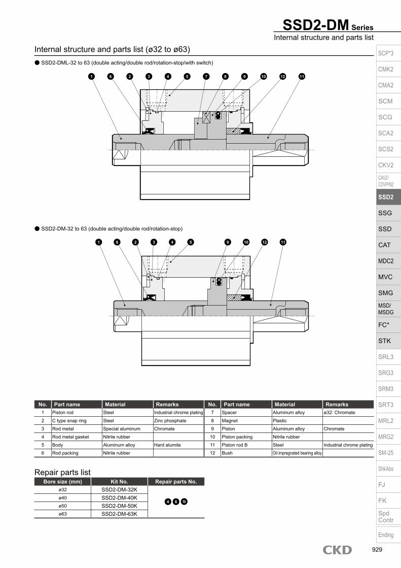
SSD2-DM-32 to 63 (double acting/double rod/rotation-stop)
SSD2-DM SeriesInternal structure and parts list
Internal structure and parts list (ø32 to ø63) SSD2-DML-32 to 63 (double acting/double rod/rotation-stop/with switch)
No. Part name Material Remarks No. Part name Material Remarks1 Piston rod Steel Industrial chrome plating 7 Spacer Aluminum alloy ø32: Chromate
2 C type snap ring Steel Zinc phosphate 8 Magnet Plastic
3 Rod metal Special aluminum Chromate 9 Piston Aluminum alloy Chromate
4 Rod metal gasket Nitrile rubber 10 Piston packing Nitrile rubber
5 Body Aluminum alloy Hard alumite 11 Piston rod B Steel Industrial chrome plating
6 Rod packing Nitrile rubber 12 Bush Oil impregnated bearing alloy
Bore size (mm) Kit No. Repair parts No.ø32 SSD2-DM-32K
4 6 10ø40 SSD2-DM-40Kø50 SSD2-DM-50Kø63 SSD2-DM-63K
Repair parts list
1 6 10
1 6 53 1172 4 8 9 10 12
2 3 4 5 9 12 11
SCP*3
CMK2
CMA2
SCM
SCG
SCA2
SCS2
CKV2
CAV2/COVP/N2
SSD2
SSG
SSD
CAT
MDC2
MVC
SMG
MSD/MSDG
FC*
STK
SRL3
SRG3
SRM3
SRT3
MRL2
MRG2
SM‑25
ShkAbs
FJ
FK
SpdContr
Ending
929

SSD2-DM Series
Dimensions SSD2-DML-12 to 25 (with switch) Rod end male thread
ø12/ø16
ø20/ø25
Codea’ c’ H kk’ M MM T wf
Bore size (mm)ø12 10.5 9 8 M5 5 6 3.2 3.5
ø16 12 10 10 M6 6 8 3.6 3.5
ø20 14 12 13 M8 8 10 5 4.5
ø25 17.5 15 17 M10×1.25 10 12 6 5
Dimensions of rod end male thread part
*1 : Only F type switch is available for the ø20 or ø25 piping port surface.*2 : HD and RD dimensions for 5 mm stroke length differ from these dimensions according to the setting.*3 : Refer to page 1044 for HD, RD and protruding dimensions of the 2-color display, off-delay, AC magnetic field proof, T1* and T8* switches.*4 : Dimensions in ( ) of FA are for the radial lead wire.*5 : For dimensions of individual accessories, refer to pages 1046 to 1049.*6 : Dimensions in ( ) of codes HD and RD are for the type with rubber cushion.*7 : The RD side can be identified with a mark on the port surface of the body.
Code Common dimensions with switchBore size (mm) A B C D EE F FA *4 FB I J K KA KK M MM N WF
ø12 39 32 5.5 10.5 M5 25 13(16.5) 4.5 3.5 6.5 spot face depth 3.5 32 M4 depth 7 M3 depth 6 5 6 15.5 3.5
ø16 39 32 5.5 10.5 M5 29 15(18.5) 4.5 3.5 6.5 spot face depth 3.5 38 M4 depth 7 M4 depth 8 6 8 20 3.5
ø20 50 41 8 13 M5 36 18.5(22) 12.5 5.5 9 spot face depth 5.5 47 M6 depth 11 M5 depth 7 8 10 25.5 4.5
ø25 54 44 11 16 M5 40 20.5(24) 13.5 5.5 9 spot face depth 5.5 51 M6 depth 11 M6 depth 12 10 12 28 5
Switch dimensions
Reed T0H/T0V, T5H/T5V *6
Proximity T2H/T2V, T3H/T3V *6
Proximity T2WH/T2WV, T3WH/T3WV *6
Proximity F2H/F2V, F3H/F3V, F2YH/F2YV, F3YH/F3YV
Proximity F2S/F3S
Bore size (mm) HD RD HD RD HD RD HD RD HD RDø12 10 2.5 10 2.5 11.5 4
ø16 10 2 10 2 11.5 3.5
ø20 14.5 6.5 14.5 6.5 16 8 19 12 18 11
ø25 16.5 9.5 16.5 9.5 18 11 20 13 19 12
Note: The positions for the left and right widths across flats are unspecified.
a’c’
T
wf
kk’Width across flats M
Width across flats H
F
8-J(Mounting hole)
N
øK
F N
FBM
FA *4
FB
FA *
4
øMM
WF
KK
C D2-EE
8-KA øI
A + (2 × stroke length)B + stroke length
KK
WF + stroke length
HD
F8-J
(Mounting hole)N
øKF N
M
FA *4
FB øMM
WF
KK
C D2-EE
8-KA
øIB + stroke length
KK
WF + stroke length
HD
A + (2 × stroke length)
RD
øMM
RD
SCP*3
CMK2
CMA2
SCM
SCG
SCA2
SCS2
CKV2
CAV2/COVP/N2
SSD2
SSG
SSD
CAT
MDC2
MVC
SMG
MSD/MSDG
FC*
STK
SRL3
SRG3
SRM3
SRT3
MRL2
MRG2
SM‑25
ShkAbs
FJ
FK
SpdContr
Ending
930

Dimensions with mounting bracket Axial foot (LB) with switch
SSD2-DML-12 to 25 -LB
Rod side flange (FA) with switch SSD2-DML-12 to 25 -FA
SSD2-DM SeriesDouble acting/double rod
Rod end male thread
Rod end male thread
Code Common dimensionsBore size
(mm) AB AG AH AK AT AU G N TR TS M
ø12 5 29.5 17 12.5 2 8 M4×10 15.5 34 44 4.8ø16 5 33.5 19 13 2 8 M4×10 20 38 48 4.8ø20 7 42 24 15 3.2 9.2 M6×16 25.5 48 62 7.2ø25 7 46 26 16.5 3.2 10.7 M6×16 28 52 66 7.2
Code Common dimensions Female thread Male threadBore size
(mm) FD FH FL FM FT N G WF1 WF2 A B a’ wf1 wf2 A B
ø12 4.5 25 45 55 5.5 15.5 M4×12 13.5 3.5 49 32 10.5 13.5 3.5 70 32ø16 4.5 30 45 55 5.5 20 M4×12 13.5 3.5 49 32 12 13.5 3.5 73 32ø20 6.6 39 48 60 8 25.5 M6×16 14.5 4.5 60 41 14 14.5 4.5 88 41ø25 6.6 42 52 64 8 28 M6×16 15 5 64 44 17.5 15 5 99 44
Code Female thread Male threadBore size
(mm) WF LF A B LX a’ wf LF A B LX
ø12 13.5 19.5 59 32 15 10.5 13.5 19.5 80 32 15ø16 13.5 19.5 59 32 15 12 13.5 19.5 83 32 15ø20 14.5 20.5 70 41 19 14 14.5 20.5 98 41 19ø25 15 22.5 74 44 19 17.5 15 22.5 109 44 19
N
AG N
TRTS
AT
AH
4-øAB
WF B + stroke length
M
AU
LX + stroke length
A + (2 × stroke length)
B + stroke lengtha’ wf
LF
LF
AK
LF + stroke length
wf + stroke length a’
LF + stroke length
WF + stroke length
Low head hexagon socketBolt 8-G
FM
NFH
N
2-FD
Mounting bolt 4-GHexagon socket button head bolt
FL
A + (2 × stroke length)
A + (2 × stroke length)
B + stroke length
FTB + stroke lengtha’ wf1
WF1 WF2 + stroke lengthwf2 + stroke length a’
A + (2 × stroke length)
SCP*3
CMK2
CMA2
SCM
SCG
SCA2
SCS2
CKV2
CAV2/COVP/N2
SSD2
SSG
SSD
CAT
MDC2
MVC
SMG
MSD/MSDG
FC*
STK
SRL3
SRG3
SRM3
SRT3
MRL2
MRG2
SM‑25
ShkAbs
FJ
FK
SpdContr
Ending
931
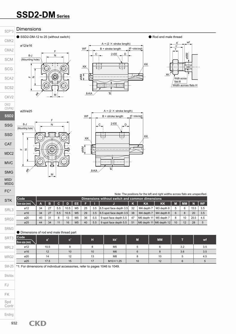
Dimensions SSD2-DM-12 to 25 (without switch) Rod end male thread
ø12/ø16
Note: The positions for the left and right widths across flats are unspecified.
*1: For dimensions of individual accessories, refer to pages 1046 to 1049.
Codea’ c’ H kk’ M MM T wf
Bore size (mm)ø12 10.5 9 8 M5 5 6 3.2 3.5
ø16 12 10 10 M6 6 8 3.6 3.5
ø20 14 12 13 M8 8 10 5 4.5
ø25 17.5 15 17 M10×1.25 10 12 6 5
Dimensions of rod end male thread part
Code Dimensions without switch and common dimensionsBore size (mm) A B C D EE F I J K KA KK M MM N WF
ø12 34 27 5.5 10.5 M5 25 3.5 6.5 spot face depth 3.5 32 M4 depth 7 M3 depth 6 5 6 15.5 3.5
ø16 34 27 5.5 10.5 M5 29 3.5 6.5 spot face depth 3.5 38 M4 depth 7 M4 depth 8 6 8 20 3.5
ø20 40 31 8 13 M5 36 5.5 9 spot face depth 5.5 47 M6 depth 11 M5 depth 7 8 10 25.5 4.5
ø25 44 34 11 16 M5 40 5.5 9 spot face depth 5.5 51 M6 depth 11 M6 depth 12 10 12 28 5
ø20/ø25
SSD2-DM Series
a’c’
T
wf
kk’Width across flats M
Width across flats H
øMM
F8-J
(Mounting hole)N
øK
F N
M
øMM
WF
KK
C D2-EE
8-KA øI
A + (2 × stroke length)
B + stroke length
KK
WF + stroke length
F8-J
(Mounting hole)N
øK
F N
M
øMM
WF
KK
C D2-EE
8-KA øI
B + stroke length
KK
WF + stroke length
A + (2 × stroke length)
SCP*3
CMK2
CMA2
SCM
SCG
SCA2
SCS2
CKV2
CAV2/COVP/N2
SSD2
SSG
SSD
CAT
MDC2
MVC
SMG
MSD/MSDG
FC*
STK
SRL3
SRG3
SRM3
SRT3
MRL2
MRG2
SM‑25
ShkAbs
FJ
FK
SpdContr
Ending
932

Dimensions with mounting bracket Axial foot (LB) without switch SSD2-DM-12 to 25 -LB
Rod side flange (FA) without switchSSD2-DM-12 to 25 -FA
SSD2-DM SeriesDouble acting/double rod
Rod end male thread
Rod end male thread
Code Female thread Male threadBore size
(mm) WF LF A B LX a’ wf LF A B LX
ø12 13.5 19.5 54 27 15 10.5 13.5 19.5 75 27 15ø16 13.5 19.5 54 27 15 12 13.5 19.5 78 27 15ø20 14.5 20.5 60 31 19 14 14.5 20.5 88 31 19ø25 15 22.5 64 34 19 17.5 15 22.5 99 34 19
Code Common dimensions Female thread Male threadBore size
(mm) FD FH FL FM FT N G WF1 WF2 A B a’ wf1 wf2 A B
ø12 4.5 25 45 55 5.5 15.5 M4×12 13.5 3.5 44 27 10.5 13.5 3.5 65 27ø16 4.5 30 45 55 5.5 20 M4×12 13.5 3.5 44 27 12 13.5 3.5 68 27ø20 6.6 39 48 60 8 25.5 M6×16 14.5 4.5 50 31 14 14.5 4.5 78 31ø25 6.6 42 52 64 8 28 M6×16 15 5 54 34 17.5 15 5 89 34
Code Common dimensionsBore size
(mm) AB AG AH AK AT AU G N TR TS M
ø12 5 29.5 17 12.5 2 8 M4×10 15.5 34 44 4.8ø16 5 33.5 19 13 2 8 M4×10 20 38 48 4.8ø20 7 42 24 15 3.2 9.2 M6×16 25.5 48 62 7.2ø25 7 46 26 16.5 3.2 10.7 M6×16 28 52 66 7.2
N
AG N
TRTS
AT
AH
4-øAB
WF B + stroke length
M
AU
LX + stroke length
A + (2 × stroke length)
B + stroke lengtha’ wf
LF
LF
AK
LF + stroke length
wf + stroke length a’
LF + stroke length
WF + stroke length
Low head hexagon socket bolt 8-G
FM
NFH
N
2-FD
Mounting bolt 4-GHexagon socket button head bolt
FL
A + (2 × stroke length)
B + stroke length
FTB + stroke lengtha’ wf1
WF1 WF2 + stroke lengthwf2 + stroke length a’
A + (2 × stroke length)
A + (2 × stroke length)
SCP*3
CMK2
CMA2
SCM
SCG
SCA2
SCS2
CKV2
CAV2/COVP/N2
SSD2
SSG
SSD
CAT
MDC2
MVC
SMG
MSD/MSDG
FC*
STK
SRL3
SRG3
SRM3
SRT3
MRL2
MRG2
SM‑25
ShkAbs
FJ
FK
SpdContr
Ending
933

SSD2-DM Series
Dimensions SSD2-DML-32 to 63 (with switch) Rod end male thread
SSD2-DM-32 to 63 (without switch)
Code Common dimensions with switchSwitch dimensions
Reed T0H/T0V, T5H/T5V Proximity T2H/T2V, T3H/T3V Proximity T2WH/T2WV, T3WH/T3WVBore size (mm) M MM N O P WF HD *4 RD *4 HD *4 RD *4 HD RD
ø32 14 16 34 4.5 21 7 20 9 20 9 21.5 10.5ø40 14 16 40 5 28 7 16.5 12 16.5 12 18 13.5ø50 17 20 50 7 35 8 16.5 12.5 16.5 12.5 18 14ø63 17 20 60 7 35 8 18 13 18 13 19.5 14.5
Codea’ c’ H kk’ M MM T wf
Bore size (mm)ø32 23.5 20.5 22 M14×1.5 14 16 8 5ø40 23.5 20.5 22 M14×1.5 14 16 8 5ø50 28.5 26 27 M18×1.5 17 20 11 5ø63 28.5 26 27 M18×1.5 17 20 11 5
Dimensions of rod end male thread part
*1 : Custom stroke length is available only for more than 50 mm stroke lengths.*2 : To calculate A + (2 x stroke length) when using a custom stroke length, apply “A + next longer standard stroke length + custom stroke length”. (Example) If the
custom stroke length is 70 mm, apply “A + standard stroke length 75 mm + custom stroke length 70 mm”.*3 : To calculate B + stroke length when using custom stroke length, apply the next longer standard stroke length instead of the custom stroke length. (Example) If the custom stroke length is 70 mm, apply the standard stroke length 75 mm.*4 : HD and RD dimensions for 5 mm stroke length differ from these dimensions according to the setting.*5 : Refer to page 1044 for HD, RD and protruding dimensions of the 2-color display, off-delay, AC magnetic field proof, T1* and T8* switches.*6 : Dimensions in ( ) of FA are for the radial lead wire.*7 : For dimensions of individual accessories, refer to pages 1046 to 1049.*8 : Dimensions in ( ) of codes A and B are for stroke lengths of more than 50 mm.*9 : The ø32 bore size with a 5 mm stroke and without a switch has a port size of M5.*10 : Dimensions in ( ) of codes C and D are when the value is for a 5 mm stroke without switch.*11 : The RD side can be identified with a mark on the port surface of the body.
Code Without switch Common dimensions with switchBore size (mm) A *2, *8 B *3, *8 A *2 B *3 C *10 D *10 EE *9 F FA *6 FB G H I J K KA KK
ø32 53.5(63.5) 39.5(49.5) 63.5 49.5 8(5.5) 18(20) Rc1/8 45 23(26.5) 20.5 49.5 12.5 5.5 9 spot face depth 5.5 60 M6 depth 11 M8 depth 13ø40 54(64) 40(50) 64 50 12 12 Rc1/8 52 26.5(30) 27.5 57 15 5.5 9 spot face depth 5.5 69 M6 depth 11 M8 depth 13ø50 56.5(66.5) 40.5(50.5) 66.5 50.5 10.5 10.5 Rc1/4 64 32.5(36) 28.5 71 18 6.9 11 spot face depth 6.5 86 M8 depth 13 M10 depth 15ø63 58(68) 42(52) 68 52 13 13 Rc1/4 77 39(42.5) 28.5 84 23 8.7 14 spot face depth 9 103 M10 depth 25 M10 depth 15
Note: The positions for the left and right widths across flats are unspecified.
a’c’T
wf
kk’Width across flats M
Width across flats H
øMM
F
8-J(Mounting hole)
N
F N FB øMM
WF
KK
C D
8-KA øI
A + (2 × stroke length)B + stroke length
FA *6
KK
WF + stroke length
HDH
OG
F
8-J(Mounting hole)
N
F N
M
øMM
WF
KK
C D
8-KA øIA + (2 × stroke length)
B + stroke length
KK
WF + stroke length
H
OG
RD
øKøK
4.5
M
2
øPh9
2-EE
2-EE
SCP*3
CMK2
CMA2
SCM
SCG
SCA2
SCS2
CKV2
CAV2/COVP/N2
SSD2
SSG
SSD
CAT
MDC2
MVC
SMG
MSD/MSDG
FC*
STK
SRL3
SRG3
SRM3
SRT3
MRL2
MRG2
SM‑25
ShkAbs
FJ
FK
SpdContr
Ending
934
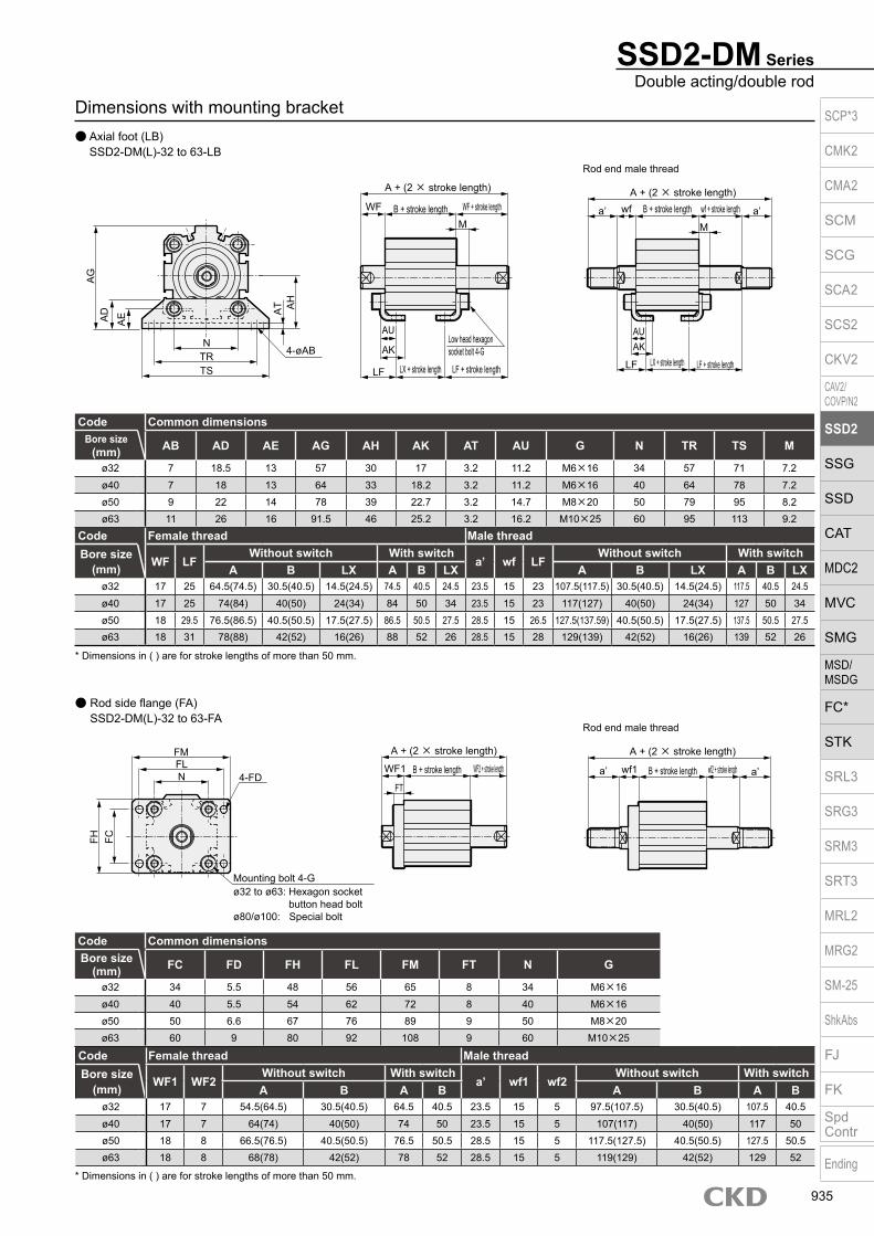
Dimensions with mounting bracket Axial foot (LB)
SSD2-DM(L)-32 to 63-LB
Rod side flange (FA) SSD2-DM(L)-32 to 63-FA
Rod end male thread
SSD2-DM SeriesDouble acting/double rod
* Dimensions in ( ) are for stroke lengths of more than 50 mm.
Code Female thread Male threadBore size
(mm) WF1 WF2Without switch With switch
a’ wf1 wf2Without switch With switch
A B A B A B A Bø32 17 7 54.5(64.5) 30.5(40.5) 64.5 40.5 23.5 15 5 97.5(107.5) 30.5(40.5) 107.5 40.5ø40 17 7 64(74) 40(50) 74 50 23.5 15 5 107(117) 40(50) 117 50ø50 18 8 66.5(76.5) 40.5(50.5) 76.5 50.5 28.5 15 5 117.5(127.5) 40.5(50.5) 127.5 50.5ø63 18 8 68(78) 42(52) 78 52 28.5 15 5 119(129) 42(52) 129 52
* Dimensions in ( ) are for stroke lengths of more than 50 mm.
Code Female thread Male threadBore size
(mm) WF LFWithout switch With switch
a’ wf LFWithout switch With switch
A B LX A B LX A B LX A B LXø32 17 25 64.5(74.5) 30.5(40.5) 14.5(24.5) 74.5 40.5 24.5 23.5 15 23 107.5(117.5) 30.5(40.5) 14.5(24.5) 117.5 40.5 24.5ø40 17 25 74(84) 40(50) 24(34) 84 50 34 23.5 15 23 117(127) 40(50) 24(34) 127 50 34ø50 18 29.5 76.5(86.5) 40.5(50.5) 17.5(27.5) 86.5 50.5 27.5 28.5 15 26.5 127.5(137.59) 40.5(50.5) 17.5(27.5) 137.5 50.5 27.5ø63 18 31 78(88) 42(52) 16(26) 88 52 26 28.5 15 28 129(139) 42(52) 16(26) 139 52 26
Code Common dimensionsBore size
(mm) AB AD AE AG AH AK AT AU G N TR TS M
ø32 7 18.5 13 57 30 17 3.2 11.2 M6×16 34 57 71 7.2ø40 7 18 13 64 33 18.2 3.2 11.2 M6×16 40 64 78 7.2ø50 9 22 14 78 39 22.7 3.2 14.7 M8×20 50 79 95 8.2ø63 11 26 16 91.5 46 25.2 3.2 16.2 M10×25 60 95 113 9.2
Code Common dimensionsBore size
(mm) FC FD FH FL FM FT N G
ø32 34 5.5 48 56 65 8 34 M6×16ø40 40 5.5 54 62 72 8 40 M6×16ø50 50 6.6 67 76 89 9 50 M8×20ø63 60 9 80 92 108 9 60 M10×25
NTRTS
4-øAB
AD
AE A
T AH
LF
a’ wf
LX + stroke length
Low head hexagon socket bolt 4-G
LF
WF
AU
AK
M
AG
A + (2 × stroke length)
B + stroke length WF + stroke length
LF + stroke length
A + (2 × stroke length)B + stroke length wf + stroke length a’
M
LX + stroke length LF + stroke length
AUAK
Rod end male thread
FH FC
FM
NFL
4-FD
Mounting bolt 4-Gø32 to ø63: Hexagon socket
button head boltø80/ø100: Special bolt
A + (2 × stroke length)
B + stroke length
FTB + stroke lengtha’ wf1WF1 WF2 + stroke length wf2 + stroke length a’
A + (2 × stroke length)
SCP*3
CMK2
CMA2
SCM
SCG
SCA2
SCS2
CKV2
CAV2/COVP/N2
SSD2
SSG
SSD
CAT
MDC2
MVC
SMG
MSD/MSDG
FC*
STK
SRL3
SRG3
SRM3
SRT3
MRL2
MRG2
SM‑25
ShkAbs
FJ
FK
SpdContr
Ending
935

Compact cylinder double acting/single rod/rubber scraper
SSD2-G Series Bore size: ø20/ø25/ø32/ø40/ø50/ø63/ø80/ø100
JIS symbol
Specifications
*1: The ø32 bore size with a 5 mm stroke and without a switch has a port size of M5.
Item SSD2-GSSD2-GL (with switch)
Bore size mm ø20 ø25 ø32 ø40 ø50 ø63 ø80 ø100Actuation Double actingWorking fluid Compressed airMax. working pressure MPa 1.0 (≈150 psi, 10 bar)Min. working pressure MPa 0.15 (≈22 psi, 1.5 bar) 0.1 (≈15 psi, 1 bar)Proof pressure MPa 1.6 (≈230 psi, 16 bar)Ambient temperature °C -10 (14°F) to 60 (140°F) (no freezing)Port size M5 Rc1/8 *1 Rc1/4 Rc3/8Stroke tolerance mm +1.0
0
Working piston speed mm/s 50 to 500 50 to 300Cushion NoneLubrication Not required (use turbine oil class 1 ISO VG32 if necessary for lubrication)Allowable absorbed energy J 0.016 0.021 0.025 0.092 0.1 0.12 0.27 0.56
Stroke length
*1: When using the type with switch, refer to the table of the min. stroke length with switch.
Bore size (mm)
Standard stroke length (mm)
Max. stroke length (mm)
Min. stroke length (mm)
ø20 5/10/15/20/2530/35/40/45/50
50
1
ø25ø32 5/10/15/20/25/30/
35/40/45/50/75/100
100
ø40ø50
10/15/20/2530/35/40/45/50
75/100
ø63ø80ø100
Custom stroke length SSD2 Series
ItemStandard products
Standard stroke length body with spacerModel No. Refer to How to order.
DescriptionA spacer is added to the standard stroke length body to adjust the stroke length in 1 mm increments.
Stroke rangeBore size Stroke range20 to 25 1 to 4932 to 100 1 to 99
Example of model No.Model No.: SSD2-G-32-38A +2 mm spacer is added to the SSD2-G-32-40 standard cylinder to create 38 mm stroke length. B + stroke length is 63 mm.
Min. stroke length with switch (2 switches)
*1: Less than 10 mm with the 2-color display, off-delay, AC magnetic field proof, T1* or T8* switch is not available.
Bore size(mm) T0H/V / T5H/V T2H/V / T3H/V
ø20
5 5
ø25ø32ø40ø50ø63ø80ø100
A + stroke length
B + stroke length
SCP*3
CMK2
CMA2
SCM
SCG
SCA2
SCS2
CKV2
CAV2/COVP/N2
SSD2
SSG
SSD
CAT
MDC2
MVC
SMG
MSD/MSDG
FC*
STK
SRL3
SRG3
SRM3
SRT3
MRL2
MRG2
SM‑25
ShkAbs
FJ
FK
SpdContr
Ending
936

SSD2-G SeriesSpecifications
Stroke length (mm) 5 10 15 20 25 30 35 40 45 50 75 100Bore size (mm) No switch Switch No switch Switch No switch Switch No switch Switch No switch Switch No switch Switch No switch Switch No switch Switch No switch Switch No switch Switch No switch Switch No switch Switch
ø20 108 163 120 195 133 208 146 221 158 233 171 246 184 259 197 272 210 285 223 298 - - - -ø25 151 242 166 257 182 273 198 289 214 305 229 320 245 336 261 352 293 384 292 383 - - - -ø32 230 344 252 366 274 388 296 410 317 431 339 453 361 475 383 497 427 519 426 540 487 648 707 755ø40 301 444 328 471 354 497 381 524 408 551 434 577 461 604 487 630 540 657 540 683 625 816 890 948ø50 - - 513 707 555 749 597 791 639 833 682 876 734 918 766 960 890 1002 850 1044 787 1254 1307 1464ø63 - - 733 1012 788 1067 843 1122 898 1177 953 1232 1009 1288 1064 1343 1175 1398 1174 1453 1384 1728 1939 2003ø80 - - 1532 1945 1619 2032 1705 2118 1792 2203 1878 2288 1965 2377 2052 2465 2226 2552 2225 2638 2564 3071 3434 3503
ø100 - - 2212 2779 2326 2893 2439 3006 2553 3120 2667 3234 2781 3348 2894 3461 3121 3575 3122 3689 3622 4259 4757 4829
Cylinder weight table (the weight of the switches is when there are 2 cylinder switches.)
Switch specifications (F type switch) 1-color/2-color display
ItemProximity 2-wire Proximity 3-wire Proximity 2-wire Proximity 3-wire
F2S F3S F2H/F2V F2YH/F2YV F3H/F3VF3PH/F3PV
(made to order)F3YH/F3YV
Applications Dedicated for programmable controller
For programmable controller, relay
Dedicated for programmable controller
For programmable controller, relay
Output method - NPN output - NPN output PNP output NPN outputPower supply voltage - 10 to 28 VDC - 10 to 28 VDC 4.5 to 28 VDC 10 to 28 VDCLoad voltage 10 to 30 VDC 30 VDC or less 10 to 30 VDC 24 VDC ±10% 30 VDC or lessLoad current 5 to 20 mA 50 mA or less 5 to 20 mA 50 mA or less
Indicator lamp LED(Lit when ON)
Yellow LED(Lit when ON)
Red/greenLED
(Lit when ON)
Yellow LED(Lit when ON)
Red/greenLED
(Lit when ON)Leakage current 1 mA or less 10 μA or less 1 mA or less 10 μA or lessWeight g 1 m:10 3 m:29
Switch specifications (T type switch) 1-color/2-color display/for AC magnetic field proof
ItemProximity 2-wire Proximity 2-wire Proximity 3-wire Reed 2-wire Proximity 2-wire
T1H/T1VT2H/T2V/
T2JH/T2JVT2YH/T2YV
T2WH/T2WV
T3H/T3V
T3PH/T3PV
T3YH/T3YV
T3WH/T3WV
T0H/T0V T5H/T5V T8H/T8VT2YD(*4)T2YDT
ApplicationsFor programmable
controller, relay, compact solenoid valve
Dedicated for programmable controller
For programmable controller, relay
For programmable controller, relay
For programmable controller, relay, IC circuit (no indicator
lamp), serial connection
For programmable controller, relay
Dedicated for programmable
controllerOutput method - NPN output PNP output NPN output NPN output -Pwr. supp. V. - 10 to 28 VDC -Load voltage 85 to 265 VAC 10 to 30 VDC 24 VDC ±10% 30 VDC or less 12/24 VDC 100/110 VAC 5/12/24 VDC 100/110 VAC 12/24 VDC 110 VAC 220 VAC 24 VDC ±10%Load current 5 to 100 mA 5 to 20 mA (*3) 100 mA or less 50 mA or less 5 to 50 mA 7 to 20 mA 50 mA or less 20 mA or less 5 to 50 mA 7 to 20 mA 7 to 10 mA 5 to 20 mA
Indicator lamp
LED(Lit when
ON)
LED(Lit when
ON)
Red/green LED
(Lit when ON)
Red/green LED
(Lit when ON)
LED(Lit when
ON)
Yellow LED
(Lit when ON)
Red/green LED
(Lit when ON)
Red/green LED
(Lit when ON)
LED(Lit when ON)
Without indicator lamp
LED(Lit when ON)
Red/green LED
(Lit when ON)Leakage current
≤ 1 mA at 100 VAC, ≤ 2 mA at 200 VAC
1 mA or less 10 μA or less 0 mA 1 mA or less
Weight g1 m:333 m:875 m:142
1 m:183 m:495 m:80
1 m:333 m:875 m:142
1 m:183 m:495 m:80
1 m:183 m:495 m:80
1 m:333 m:875 m:142
1 m:183 m:495 m:80
1 m:18 3 m:49 5 m:801 m:333 m:875 m:142
1 m:613 m:1665 m:272
*1 : Refer to Ending Page 1 for detailed switch specifications and dimensions. *2 : Switches other than the above models, such as switches with connectors, are also available. Refer to Ending Page 1. *3 : The max. load current is 20 mA at 25°C. The current is lower than 20 mA if the operating ambient temperature around the switch is higher than 25˚C.
(5 to 10 mA at 60°C) *4 : Switch for AC magnetic field (T2YD/T2YDT) cannot be used in DC magnetic field. *5 : The F type switch uses a bend-resistant lead wire.
Bore size (mm)
Operating direction
Working pressure MPa0.1 0.15 0.2 0.3 0.4 0.5 0.6 0.7 0.8 0.9 1.0
ø20Push - 47.1 62.8 94.2 1.26× 10² 1.57× 10² 1.88× 10² 2.20× 10² 2.51× 10² 2.83× 10² 3.14× 10²
Pull - 35.3 47.1 70.7 94.2 1.18× 10² 1.41× 10² 1.65× 10² 1.88× 10² 2.12× 10² 2.36× 10²
ø25Push - 73.6 98.2 1.47× 10² 1.96× 10² 2.45× 10² 2.95× 10² 3.44× 10² 3.93× 10² 4.42× 10² 4.91× 10²
Pull - 56.7 75.6 1.13× 10² 1.51× 10² 1.89× 10² 2.27× 10² 2.64× 10² 3.02× 10² 3.40× 10² 3.78× 10²
ø32Push - 1.21× 10² 1.61× 10² 2.41× 10² 3.22× 10² 4.02× 10² 4.83× 10² 5.63× 10² 6.43× 10² 7.24× 10² 8.04× 10²
Pull - 90.5 1.21× 10² 1.81× 10² 2.41× 10² 3.02× 10² 3.62× 10² 4.22× 10² 4.83× 10² 5.43× 10² 6.03× 10²
ø40Push - 1.88× 10² 2.51× 10² 3.77× 10² 5.03× 10² 6.28× 10² 7.54× 10² 8.80× 10² 1.01× 10³ 1.13× 10³ 1.26× 10³
Pull - 1.58× 10² 2.11× 10² 3.17× 10² 4.22× 10² 5.28× 10² 6.33× 10² 7.39× 10² 8.44× 10² 9.50× 10² 1.06× 10³
ø50Push - 2.95× 10² 3.93× 10² 5.89× 10² 7.85× 10² 9.82× 10² 1.18× 10³ 1.37× 10³ 1.57× 10³ 1.77× 10³ 1.96× 10³
Pull - 2.47× 10² 3.30× 10² 4.95× 10² 6.60× 10² 8.25× 10² 9.90× 10² 1.15× 10³ 1.32× 10³ 1.48× 10³ 1.65× 10³
ø63Push 3.12× 10² 4.68× 10² 6.23× 10² 9.35× 10² 1.25× 10³ 1.56× 10³ 1.87× 10³ 2.18× 10³ 2.49× 10³ 2.81× 10³ 3.12× 10³
Pull 2.80× 10² 4.20× 10² 5.61× 10² 8.41× 10² 1.12× 10³ 1.40× 10³ 1.68× 10³ 1.96× 10³ 2.24× 10³ 2.52× 10³ 2.80× 10³
ø80Push 5.03× 10² 7.54× 10² 1.01× 10³ 1.51× 10³ 2.01× 10³ 2.51× 10³ 3.02× 10³ 3.52× 10³ 4.02× 10³ 4.52× 10³ 5.03× 10³
Pull 4.54× 10² 6.80× 10² 9.07× 10² 1.36× 10³ 1.81× 10³ 2.27× 10³ 2.72× 10³ 3.17× 10³ 3.63× 10³ 4.08× 10³ 4.54× 10³
ø100Push 7.85× 10² 1.18× 10³ 1.57× 10³ 2.36× 10³ 3.14× 10³ 3.93× 10³ 4.71× 10³ 5.50× 10³ 6.28× 10³ 7.07× 10³ 7.85× 10³
Pull 7.15× 10² 1.07× 10³ 1.43× 10³ 2.14× 10³ 2.86× 10³ 3.57× 10³ 4.29× 10³ 5.00× 10³ 5.72× 10³ 6.43× 10³ 7.15× 10³
Theoretical thrust table (Unit: N)
(Unit: g)
SCP*3
CMK2
CMA2
SCM
SCG
SCA2
SCS2
CKV2
CAV2/COVP/N2
SSD2
SSG
SSD
CAT
MDC2
MVC
SMG
MSD/MSDG
FC*
STK
SRL3
SRG3
SRM3
SRT3
MRL2
MRG2
SM‑25
ShkAbs
FJ
FK
SpdContr
Ending
937

SSD2-G Series
Precautions for model No. selection*1 : The T8* switch cannot be mounted on the ø20 to
ø32 bore sizes.*2 : The F type switch can only be mounted on the piping
port surface of bore sizes ø20 and ø25.*3 : The mounting bracket is included at shipment.*4 : “I” and “Y” cannot be selected together.*5 : The F type switch with L type lead wire on ø20
models cannot be selected on stroke lengths of 15 mm or under.
*6 : Switches are shipped with the product. Contact CKD if assembling before shipment is necessary.
*7 : F type switch cannot be selected.*8 : The structure of bore sizes ø20 to ø32 does not
permit retrofitting of the foot bracket (LB) or flange bracket (FA) on the rod side. Assembly before shipment is available as made to order.
[Example of model No.]SSD2-GL-20-10-T0H-R-N-LB-IModel: Compact cylinder rubber scraperB Bore size : ø20 mmC Stroke length : 10 mmD Switch model No. : Reed T0H switch/ Lead wire length 1 mE Switch quantity : 1 on rod sideF Option : Rod end male threadG Mounting bracket : Axial footH Accessory : Rod eye
Model No.A
Accessory *4
H
OptionF
How to orderWithout switch (without magnet for switch)
With switch (built-in magnet for switch)
32 IN5
Mounting bracket *3*8
G
Switch quantityE
*1*2*5*6
Switch model No.D
Stroke lengthC
Bore size
B
32 R10 IN
Code DescriptionModel No.
SSD2-G Double acting/single rod/rubber scraperSSD2-GL Double acting/single rod/rubber scraper/with switch
Bore size (mm)20 ø2025 ø2532 ø3240 ø4050 ø5063 ø6380 ø80100 ø100
Stroke length (mm)
Refer to the stroke length table on the following page.
* Lead wire lengthBlank 1 m (standard)
3 3 m (option)5 5 m (option) *7
Switch quantityR 1 on rod sideH 1 on head sideD 2
OptionBlank Rod end female thread
N Rod end male thread
Mounting bracketBlank Without mounting bracket
LB Axial foot (made-to-order product)CB Clevis bracket (pin and snap ring included)FA Rod side flange (made-to-order product)FB Head side flange
Accessory (available when rod end male thread “N” is selected)I Rod eyeY Rod clevis (pin and snap ring included)
A
B
C
F
G
H
Switch model No.Lead wire Lead wire
Conta
ct Voltage DisplayLead wire
Bore sizeStraight L-shaped AC DC 20 25 32 40 50 63 80 100
- F2S*
Pro
xim
ity
1-color display
2-wire - F3S* 3-wire
F2H* F2V* 2-wire F3H* F3V* 3-wire
F3PH* F3PV* 1 color display (PNP output) (custom) 3-wire F2YH* F2YV*
2-color display2-wire
F3YH* F3YV* 3-wire T0H* T0V*
Ree
d 1-color display2-wire
T5H* T5V* Without indicator lamp T8H* T8V* 1-color display T1H* T1V*
Pro
xim
ity
1-color display
2-wire
T2H* T2V* T3H* T3V*
3-wire
T3PH* T3PV* 1-color display (PNP output) T2WH* T2WV*
2-color display2-wire
T2YH* T2YV* T3WH* T3WV*
3-wire
T3YH* T3YV* T2YD* - 2-color display
AC magnetic field 2-wire
T2YDT* - T2JH* T2JV* 1-color display off-delay 2-wire
D
E
SSD2-G
SSD2-GL T0H
LB
LB
SCP*3
CMK2
CMA2
SCM
SCG
SCA2
SCS2
CKV2
CAV2/COVP/N2
SSD2
SSG
SSD
CAT
MDC2
MVC
SMG
MSD/MSDG
FC*
STK
SRL3
SRG3
SRM3
SRT3
MRL2
MRG2
SM‑25
ShkAbs
FJ
FK
SpdContr
Ending
938

SSD2-G SeriesHow to order
Stroke length (mm)Applicable bore size
20 25 32 40 50 63 80 100
Sta
ndar
d st
roke
leng
th
5 10 15 20 25 30 35 40 45 50 75
100 Min. stroke length (mm) *1 1Max. stroke length (mm) 50 100Custom stroke length *2 In 1 mm increments
*1 : Less than 5 mm for 1-color display switch and less than 10 mm for the 2-color display, off-delay, AC magnetic field proof, T1* or T8* switch are not available.
Refer to page 936 for the min. stroke length with switch.*2 : The total length when using a custom stroke length is the same as that when using the next longer standard
stroke length.
Bore size (mm)ø20 ø25 ø32 ø40 ø50 ø63 ø80
Mounting bracketFoot (LB) SSD2-LB-40 SSD2-LB-50 SSD2-LB-63 SSD2-LB-80Flange (FA/FB) SSD2-FA-40 SSD2-FA-50 SSD2-FA-63 SSD2-FA-80Clevis bracket (CB) SSD2-CB-20 SSD2-CB-25 SSD2-CB-32 SSD2-CB-40 SSD2-CB-50 SSD2-CB-63 SSD2-CB-80
Bore size (mm)ø100
Mounting bracketFoot (LB) SSD2-LB-100Flange (FA/FB) SSD2-FA-100Clevis bracket (CB) SSD2-CB-100
How to order switch
Switch model No. (Item D on page 938)
*1: The foot mounting bracket is provided as 2 pcs./set.*2: The structure of bore sizes ø20 to ø32 does not permit retrofitting of the foot bracket (LB) or flange bracket (FA) on the rod side. Contact CKD for details.
[Stroke length table]
How to order mounting bracket
SW T0H
SCP*3
CMK2
CMA2
SCM
SCG
SCA2
SCS2
CKV2
CAV2/COVP/N2
SSD2
SSG
SSD
CAT
MDC2
MVC
SMG
MSD/MSDG
FC*
STK
SRL3
SRG3
SRM3
SRT3
MRL2
MRG2
SM‑25
ShkAbs
FJ
FK
SpdContr
Ending
939

Internal structure and parts list
SSD2-G Series
SSD2-GL-20, 25 (double acting/single rod/rubber scraper/ with switch)
SSD2-GL-32 (double acting/single rod/rubber scraper/ with switch)
SSD2-G-20, 25 (double acting/single rod/rubber scraper) SSD2-G-32 (double acting/single rod/rubber scraper)
No. Part name Material Remarks No. Part name Material Remarks
1 Piston rod ø20, ø25: Stainless steelø32: Steel
Industrial chrome plating
9 Magnet Plastic
10 Piston Aluminum alloy Chromate
2 Scraper Nitrile rubber 11 Piston packing Nitrile rubber
3 C type snap ring Stainless steel12 Cover ø20 to ø25: Stainless steel
ø32: Aluminum alloy ø32: Alumite4 Rod packing Nitrile rubber
5 Rod metal gasket Nitrile rubber 13 Hexagon socket head cap screw Stainless steel
6 Rod metal Special aluminum Alumite 14 Adaptor (A) Aluminum alloy Alumite
7 Body Aluminum alloy Hard alumite 15 Adaptor (B) Aluminum alloy Alumite
8 Spacer Aluminum alloy Chromate
Part nameKit No. Repair parts No.
Bore size (mm)ø20 SSD2-G-20K
2 4 5 11ø25 SSD2-G-25Kø32 SSD2-G-32K
Repair parts list
1 14 2 15 3 4 76 8 9 11 10 125
1 14 15 2 3 4 76 11 10 125 1 14 15 2 3 5 76 11 10 124 8
1 14 15 2 3 5 76 8 9 11 10 124
13
13
13
13
Over 50 st
SCP*3
CMK2
CMA2
SCM
SCG
SCA2
SCS2
CKV2
CAV2/COVP/N2
SSD2
SSG
SSD
CAT
MDC2
MVC
SMG
MSD/MSDG
FC*
STK
SRL3
SRG3
SRM3
SRT3
MRL2
MRG2
SM‑25
ShkAbs
FJ
FK
SpdContr
Ending
940

SSD2-G SeriesInternal structure and parts list
Internal structure and parts list SSD2-GL-40, 50 (double acting/single rod/rubber scraper/
with switch) SSD2-GL-63 to 100 (double acting/single rod/rubber scraper/
with switch)
SSD2-G-40, 50 (double acting/single rod/rubber scraper) SSD2-G-63 to 100 (double acting/single rod/rubber scraper)
No. Part name Material Remarks No. Part name Material Remarks1 Piston rod Steel Industrial chrome plating 7 Body Aluminum alloy Hard alumite
2 Scraper Nitrile rubber 8 Spacer Aluminum alloy Chromate
3 C type snap ring Stainless steel 9 Magnet Plastic
4 Rod packing Nitrile rubber 10 Piston Aluminum alloy Chromate
5 Rod metal gasket Nitrile rubber 11 Piston packing Nitrile rubber
6 Rod metal ø40, ø50: Special aluminumø63 to ø100: Aluminum alloy
ø40, ø50: Alumiteø63 to ø100: Chromate
12 Cover Aluminum alloy Alumite
13 Bush Oiles drymet ø63 to ø100 only
Part nameKit No. Repair parts No.
Bore size (mm)ø40 SSD2-G-40K
2 4 5 11
ø50 SSD2-G-50Kø63 SSD2-G-63Kø80 SSD2-G-80K
ø100 SSD2-G-100K
Repair parts list
1 2 3 4 76 8 9 11 10 125
1 2 3 4 76 11 10 12 85 1 2 34 713 11 10 12 85 6
1 2 4 3 75 8 9 11 10 126 13
Over 50 st
Over 50 st
SCP*3
CMK2
CMA2
SCM
SCG
SCA2
SCS2
CKV2
CAV2/COVP/N2
SSD2
SSG
SSD
CAT
MDC2
MVC
SMG
MSD/MSDG
FC*
STK
SRL3
SRG3
SRM3
SRT3
MRL2
MRG2
SM‑25
ShkAbs
FJ
FK
SpdContr
Ending
941

SSD2-G Series
Dimensions SSD2-G(L)
Code Dimensions without switch Common dimensions with switchBore size (mm) A *1, *4 B *1, *4 Q A *1 B *1 Q C D EE *5 F FA *6 FB G H I J K KA KK
ø20 34 29.5 19.5 44 39.5 29.5 18 5.5 M5 36 18.5(22) 12.5 - - 5.5 9 spot face depth 5.5 (15.5) 47 M6 depth 11 M5 depth 7
ø25 37.5 32.5 22.5 47.5 42.5 32.5 21 6 M5 40 20.5(24) 13.5 - - 5.5 9 spot face depth 5.5 (15.5) 51 M6 depth 11 M6 depth 12
ø32 40(50) 33(43) 23(33) 50 43 33 18 8 Rc1/8 45 23(26.5) 20.5 49.5 12.5 5.5 9 spot face depth 5.5 (15.5) 60 M6 depth 11 M8 depth 13
ø40 46.5(56.5) 29.5(39.5) - 56.5 39.5 - 12 8.5 Rc1/8 52 26.5(30) 27.5 57 15 5.5 9 spot face depth 5.5 69 M6 depth 11 M8 depth 13
ø50 48.5(58.5) 30.5(40.5) - 58.5 40.5 - 10.5 10.5 Rc1/4 64 32.5(36) 28.5 71 18 6.9 11 spot face depth 6.5 86 M8 depth 13 M10 depth 15
ø63 54(64) 36(46) - 64 46 - 13 11 Rc1/4 77 39(42.5) 28.5 84 23 8.7 14 spot face depth 9 103 M10 depth 25 M10 depth 15
ø80 63.5(73.5) 43.5(53.5) - 73.5 53.5 - 16 13 Rc3/8 98 49.5(53) 28.5 104 31 10.5 17.5 spot face depth 11 132 M12 depth 28 M16 depth 21
ø100 75(85) 53(63) - 85 63 - 23 15 Rc3/8 117 59(62.5) 28.5 123.5 38 10.5 17.5 spot face depth 11 156 M12 depth 28 M20 depth 27
Code Common dimensions with switch Reed T0H/T0V, T5H/T5V
Proximity T2H/T2V, T3H/T3V
Proximity T2WH/T2WV, T3WH/T3WV
Proximity F2H/F2V, F3H/F3V, F2YH /
F2YV, F3YH F3YVProximity F2S/F3S
Dimensions of rod end male thread partBore size
(mm)M MM N O U WF a’ c’ H KK’ M MM T wf
HD RD HD RD HD RD HD RD HD RDø20 8 10 25.5 - - 4.5 3 17.5 3 17.5 5 19.5 7.5 22 6.5 21 14 12 13 M8 8 10 5 4.5
ø25 10 12 28 - - 5 4 19.5 4 19.5 6 21.5 8.5 24 7.5 23 17.5 15 17 M10×1.25 10 12 6 5
ø32 14 16 34 4.5 - 7 4 19.5 4 19.5 6 21.5 23.5 20.5 22 M14×1.5 14 16 8 5
ø40 14 16 40 5 28 17 7 12 7 12 8.5 13.5 23.5 20.5 22 M14×1.5 14 16 8 15
ø50 17 20 50 7 35 18 7.5 12.5 7.5 12.5 9 14 28.5 26 27 M18×1.5 17 20 11 15
ø63 17 20 60 7 35 18 12.5 13 12.5 13 14 14.5 28.5 26 27 M18×1.5 17 20 1 15
ø80 22 25 77 6 43 20 17.5 15.5 17.5 15.5 19 17 35.5 32.5 32 M22×1.5 22 25 13 18
ø100 27 30 94 6.5 59 22 23 19.5 23 19.5 24.5 21 35.5 32.5 41 M26×1.5 27 30 16 18
*1 : To calculate A+ stroke length or B+ stroke length when using custom stroke length, apply the next longer standard stroke length (instead of the custom stroke length) to the stroke length value. (Example) If the custom stroke length is 7 mm, apply the standard stroke length of 10 mm.
*2 : HD and RD dimensions for 5 mm stroke length differ from these dimensions according to the setting.*3 : For dimensions of individual accessories, refer to pages 1046 to 1049.*4 : Dimensions in ( ) of codes A, B and Q are for stroke lengths of more than 50 mm.*5 : The ø32 bore size with a 5 mm stroke and without a switch has a port size of M5.*6 : Dimensions in ( ) of FA are for the radial lead wire.*7 : Dimensions in ( ) of code J are for the rod side mounting hole.
ø32 ø40 to ø100
Rod end male thread
ø20/ø25
G F N
øK
FNH
M
FA
6-JMounting hole
øMM
FB
KK
WF
A + stroke length
B + stroke lengthQ + stroke length10
C DHD
2-EE
RD øI
A + stroke length
B + stroke lengthF
N
HNF FB
M
FA
øK
G
øMM
øU
WF
5 C8-JMounting hole D
HD2-EE
RD øI
KK
FN
NF FB
MFA
øK
6-JMounting hole
WF
A + stroke lengthB + stroke length
Q + stroke length10
C DHD 2-EE
RDøI
øMM
a’ wf
c’T
øMM
KK’Width across flats H
Width across flats M
KK
8-KA 8-KA
8-KA
O
O
SCP*3
CMK2
CMA2
SCM
SCG
SCA2
SCS2
CKV2
CAV2/COVP/N2
SSD2
SSG
SSD
CAT
MDC2
MVC
SMG
MSD/MSDG
FC*
STK
SRL3
SRG3
SRM3
SRT3
MRL2
MRG2
SM‑25
ShkAbs
FJ
FK
SpdContr
Ending
942
M E M OM E M OSCP*3
CMK2
CMA2
SCM
SCG
SCA2
SCS2
CKV2
CAV2/COVP/N2
SSD2
SSG
SSD
CAT
MDC2
MVC
SMG
MSD/MSDG
FC*
STK
SRL3
SRG3
SRM3
SRT3
MRL2
MRG2
SM‑25
ShkAbs
FJ
FK
SpdContr
Ending
943

Dimensions with mounting bracket
SSD2-G Series
Clevis bracket (CB)SSD2-G(L)-20 to 100 -CB
· ø20/ø25 · ø32 to ø100
Code Female thread Male threadBore size
(mm)WF
Without switch With switcha’ wf
Without switch With switchA B CJ A B CJ A B CJ A B CJ
ø20 4.5 61 29.5 52 71 39.5 62 14 4.5 75 29.5 52 85 39.5 62
ø25 5 67.5 32.5 57.5 77.5 42.5 67.5 17.5 5 85 32.5 57.5 95 42.5 67.5
ø32 7 70 33 60 80 43 70 23.5 5 91.5 33 58 101.5 43 68
ø40 17 78.5 29.5 68.5 88.5 39.5 78.5 23.5 15 100 29.5 66.5 110 39.5 76.5
ø50 18 90.5 30.5 76.5 100.5 40.5 86.5 28.5 15 116 30.5 73.5 126 40.5 83.5
ø63 18 98 36 84 108 46 94 28.5 15 123.5 36 81 133.5 46 91
ø80 20 119.5 43.5 101.5 129.5 53.5 111.5 35.5 18 153 43.5 99.5 163 53.5 109.5
ø100 22 142 53 120 152 63 130 35.5 18 173.5 53 116 183.5 63 126
Code Common dimensionsBore size
(mm)AC CA CB CC CD D E G MR N UB
ø20 - 20 8.2 12 8 5 36 M6×16 - 25.5 16
ø25 - 24 10.2 14 10 5 40 M6×16 - 28 20
ø32 4.5 - 18.2 14 10 5 45 M6×16 10 34 36
ø40 5 - 18.2 14 10 6 52 M6×16 10 40 36
ø50 6 - 22.2 20 14 7 64 M8×20 14 50 44
ø63 7 - 22.2 20 14 8 77 M10×25 14 60 44
ø80 9 - 28.2 27 18 10 98 M12×40 18 77 56
ø100 12 - 32.2 31 22 13 117 M12×40 22 94 64
NN
WF
A + stroke lengthB + stroke lengtha’ wf
A + stroke length
Rod end male thread
B + stroke lengtha’ wf
A + stroke lengthB + stroke lengthWF
Rod end male thread
A + stroke lengthB + stroke length
H
CJ + stroke length
Mounting bolt 4-C
N
E
E
CB+0.2 0
CB+0.2 0
CC
UB-0.1-0.3 UB-0.1
-0.3
D
øCA
CD H10
CJ + stroke length
CJ + stroke length
CJ + stroke length
CCD
NE
E
CD H10
Mounting bolt 4-CAC
R MR
SCP*3
CMK2
CMA2
SCM
SCG
SCA2
SCS2
CKV2
CAV2/COVP/N2
SSD2
SSG
SSD
CAT
MDC2
MVC
SMG
MSD/MSDG
FC*
STK
SRL3
SRG3
SRM3
SRT3
MRL2
MRG2
SM‑25
ShkAbs
FJ
FK
SpdContr
Ending
944

Dimensions with mounting bracket Head side flange (FB)
SSD2-G(L)-20 to 100 -FB
· ø20/ø25 · ø32 to ø100
SSD2-G SeriesDimensions with mounting bracket
Code Common dimensions Female thread Male thread
Bore size (mm) FC FD FH FL FM FT N G WF
Without switch With switcha’ wf
Without switch With switchA B A B A B A B
ø20 - 6.6 39 48 60 8 25.5 M6×16 4.5 42 29.5 52 39.5 14 4.5 56 29.5 66 39.5
ø25 - 6.6 42 52 64 8 28 M6×16 5 45.5 32.5 55.5 42.5 17.5 5 63 32.5 73 42.5
ø32 34 5.5 48 56 65 8 34 M6×16 7 48 33 58 43 23.5 5 69.5 33 79.5 43
ø40 40 5.5 54 62 72 8 40 M6×16 17 54.5 29.5 64.5 39.5 23.5 15 76 29.5 86 39.5
ø50 50 6.6 67 76 89 9 50 M8×20 18 57.5 30.5 67.5 40.5 28.5 15 83 30.5 93 40.5
ø63 60 9 80 92 108 9 60 M10×25 18 63 36 73 46 28.5 15 88.5 36 98.5 46
ø80 77 11 99 116 134 11 77 M12×40 20 74.5 43.5 84.5 53.5 35.5 18 108 43.5 118 53.5
ø100 94 11 117 136 154 11 94 M12×40 22 86 53 96 63 35.5 18 117.5 53 127.5 63
N
FM
FHWF
Mounting bolt 4-GHexagon socket button head bolt
FH FC
A + stroke length
B + stroke lengtha’ wf FT
A + stroke length
Rod end male thread
B + stroke lengtha’ wf
A + stroke lengthB + stroke length
FLWF
FT
Rod end male thread
A + stroke length
B + stroke length FT N
2-FD
4-FDFLN
Mounting bolt 4-G
FM
FT
ø32 to ø63: Hexagon socket button head boltø80/ø100: Special bolt
SCP*3
CMK2
CMA2
SCM
SCG
SCA2
SCS2
CKV2
CAV2/COVP/N2
SSD2
SSG
SSD
CAT
MDC2
MVC
SMG
MSD/MSDG
FC*
STK
SRL3
SRG3
SRM3
SRT3
MRL2
MRG2
SM‑25
ShkAbs
FJ
FK
SpdContr
Ending
945

Compact cylinder Double acting/coolant proof
SSD2-G2/G3 Series Bore size: ø16/ø20/ø25/ø32/ø40/ø50/ø63/ø80/ø100
SpecificationsItem
SSD2-G2/G3SSD2-G2L/G3L (with switch)
Bore size mm ø16 ø20 ø25 ø32 ø40 ø50 ø63 ø80 ø100Actuation Double actingWorking fluid Compressed airMax. working pressure MPa 1.0 (≈150 psi, 10 bar)Min. working pressure MPa 0.15 (≈22 psi, 1.5 bar) 0.1 (≈15 psi, 1 bar)Proof pressure MPa 1.6 (≈230 psi, 16 bar)Ambient temperature °C -10 (14°F) to 60 (140°F) (no freezing)Port size M5 Rc1/8 (*1) Rc1/4 Rc3/8Stroke tolerance mm +1.0
0
Working piston speed mm/s 50 to 500 50 to 300Cushion NoneLubrication Not required (use turbine oil class 1 ISO VG32 if necessary for lubrication)
JIS symbol
*1: The ø32 bore size with a 5 mm stroke and without a switch has a port size of M5.
Stroke lengthBore size (mm) Standard stroke length (mm) Max. stroke length (mm) Min. stroke length (mm)
ø16 5/10/15/20/25/30 30
1(10)The value in ( ) is for types with one or two switches.
ø20 5/10/15/20/25/ 30/35/40/45/50
50ø25ø32 5/10/15/20/25/30/
35/40/45/50/75/100100
ø40ø50
10/15/20/25/ 30/35/40/45/ 50/75/100
100ø63ø80ø100
Custom stroke length SSD2-G2/G3 Series
ItemStandard products
Standard stroke length body with spacerModel No. Refer to How to order.
DescriptionA spacer is added to the standard stroke length body to adjust the stroke length in 1 mm increments.
Stroke range
Bore size Stroke range16 1 to 29
20 to 25 1 to 4932 to 100 1 to 99
Example of model No.Model No.: SSD2-G2-32-38A +2 mm spacer is added to the SSD2-G2-32-40 standard cylinder to create 38 mm stroke length. B + stroke length is 73 mm.
A + stroke length
B + stroke length
SCP*3
CMK2
CMA2
SCM
SCG
SCA2
SCS2
CKV2
CAV2/COVP/N2
SSD2
SSG
SSD
CAT
MDC2
MVC
SMG
MSD/MSDG
FC*
STK
SRL3
SRG3
SRM3
SRT3
MRL2
MRG2
SM‑25
ShkAbs
FJ
FK
SpdContr
Ending
946

SSD2-G2/G3 SeriesSpecifications
Stroke length (mm) 5 10 15 20 25 30 35 40 45 50 75 100Bore size (mm) No switch Switch No switch Switch No switch Switch No switch Switch No switch Switch No switch Switch No switch Switch No switch Switch No switch Switch No switch Switch No switch Switch No switch Switch
ø16 62 118 73 118 83 158 94 139 105 150 116 161 - - - - - - - - - - - -ø20 108 163 120 195 133 208 146 221 158 233 171 246 184 259 197 272 210 285 223 298 - - - -ø25 151 242 166 257 182 273 198 289 214 305 229 320 245 336 261 352 293 384 292 383 - - - -ø32 230 344 252 366 274 388 296 410 317 431 339 453 361 475 383 497 427 519 426 540 487 648 707 755ø40 301 444 328 471 354 497 381 524 408 551 434 577 461 604 487 630 540 657 540 683 625 816 890 948ø50 - - 513 707 555 749 597 791 639 833 682 876 734 918 766 960 890 1002 850 1044 787 1254 1307 1464ø63 - - 733 1012 788 1067 843 1122 898 1177 953 1232 1009 1288 1064 1343 1175 1398 1174 1453 1384 1728 1939 2003ø80 - - 1532 1945 1619 2032 1705 2118 1792 2203 1878 2288 1965 2377 2052 2465 2226 2552 2225 2638 2564 3071 3434 3503
ø100 - - 2212 2779 2326 2893 2439 3006 2553 3120 2667 3234 2781 3348 2894 3461 3121 3575 3122 3689 3622 4259 4757 4829
Cylinder weight table (the weight of the switches is when there are 2 cylinder switches.)
Switch specifications Proximity switch
Model No. Proximity/2-wire Proximity/3-wireItem T2YLH/T2YLV T3YLH/T3YLV
Applications Dedicated for programmable controller Programmable controller, relayPower supply voltage - 10 to 28 VDCLoad voltage/current 10 to 30 VDC, 5 to 20 mA *1 30 VDC or less, 50 mA or lessIndicator lamp Red/green LED (Lit when ON)Leakage current 1 mA or less 10 μA or lessMax. shock resistance 980 m/S2
Weight g 1 m:33 3 m:87 5 m:142*1 : The above max. load current is 20 mA at 25°C. The current is lower than 20 mA if the operating ambient temperature around the switch is higher than 25˚C.
(5 to 10 mA at 60˚C)*2 : Refer to Ending Page 1 for other switch specifications.
Bore size (mm)
Operating direction
Working pressure MPa0.1 0.15 0.2 0.3 0.4 0.5 0.6 0.7 0.8 0.9 1.0
ø16Push - 30.2 40.2 60.3 80.4 1.01×10² 1.21×10² 1.41×10² 1.61×10² 1.81×10² 2.01×10²
Pull - 22.6 30.2 45.2 60.3 75.4 90.5 1.06×10² 1.21×10² 1.36×10² 1.51×10²
ø20Push - 47.1 62.8 94.2 1.26×10² 1.57×10² 1.88×10² 2.20×10² 2.51×10² 2.83×10² 3.14×10²
Pull - 35.3 47.1 70.7 94.2 1.18×10² 1.41×10² 1.65×10² 1.88×10² 2.12×10² 2.36×10²
ø25Push - 73.6 98.2 1.47×10² 1.96×10² 2.45×10² 2.95×10² 3.44×10² 3.93×10² 4.42×10² 4.91×10²
Pull - 56.7 75.6 1.13×10² 1.51×10² 1.89×10² 2.27×10² 2.64×10² 3.02×10² 3.40×10² 3.78×10²
ø32Push - 1.21×10² 1.61×10² 2.41×10² 3.22×10² 4.02×10² 4.83×10² 5.63×10² 6.43×10² 7.24×10² 8.04×10²
Pull - 90.5 1.21×10² 1.81×10² 2.41×10² 3.02×10² 3.62×10² 4.22×10² 4.83×10² 5.43×10² 6.03×10²
ø40Push - 1.88×10² 2.51×10² 3.77×10² 5.03×10² 6.28×10² 7.54×10² 8.80×10² 1.01×10³ 1.13×10³ 1.26×10³
Pull - 1.58×10² 2.11×10² 3.17×10² 4.22×10² 5.28×10² 6.33×10² 7.39×10² 8.44×10² 9.50×10² 1.06×10³
ø50Push - 2.95×10² 3.93×10² 5.89×10² 7.85×10² 9.82×10² 1.18×10³ 1.37×10³ 1.57×10³ 1.77×10³ 1.96×10³
Pull - 2.47×10² 3.30×10² 4.95×10² 6.60×10² 8.25×10² 9.90×10² 1.15×10³ 1.32×10³ 1.48×10³ 1.65×10³
ø63Push 3.12×10² 4.68×10² 6.23×10² 9.35×10² 1.25×10³ 1.56×10³ 1.87×10³ 2.18×10³ 2.49×10³ 2.81×10³ 3.12×10³
Pull 2.80×10² 4.20×10² 5.61×10² 8.41×10² 1.12×10³ 1.40×10³ 1.68×10³ 1.96×10³ 2.24×10³ 2.52×10³ 2.80×10³
ø80Push 5.03×10² 7.54×10² 1.01×10³ 1.51×10³ 2.01×10³ 2.51×10³ 3.02×10³ 3.52×10³ 4.02×10³ 4.52×10³ 5.03×10³
Pull 4.54×10² 6.80×10² 9.07×10² 1.36×10³ 1.81×10³ 2.27×10³ 2.72×10³ 3.17×10³ 3.63×10³ 4.08×10³ 4.54×10³
ø100Push 7.85×10² 1.18×10³ 1.57×10³ 2.36×10³ 3.14×10³ 3.93×10³ 4.71×10³ 5.50×10³ 6.28×10³ 7.07×10³ 7.85×10³
Pull 7.15×10² 1.07×10³ 1.43×10³ 2.14×10³ 2.86×10³ 3.57×10³ 4.29×10³ 5.00×10³ 5.72×10³ 6.43×10³ 7.15×10³
Theoretical thrust table (Unit: N)
(Unit: g)
SCP*3
CMK2
CMA2
SCM
SCG
SCA2
SCS2
CKV2
CAV2/COVP/N2
SSD2
SSG
SSD
CAT
MDC2
MVC
SMG
MSD/MSDG
FC*
STK
SRL3
SRG3
SRM3
SRT3
MRL2
MRG2
SM‑25
ShkAbs
FJ
FK
SpdContr
Ending
947

SSD2-G2/G3 Series
*1 : The F type switch can only be mounted on the piping port surface of bore sizes ø20 and ø25.
*2 : The mounting bracket is included at shipment.*3 : The structure of bore sizes ø16 to ø32 does not permit
retrofitting of the foot bracket (LB) or flange bracket (FA) on the rod side. Assembly before shipment is available as made to order.
*4 : “I” and “Y” cannot be selected together.*5 : Refer to pages 750 and 751 for combinations of
variations/options.*6 : Switches are shipped with the product. Contact CKD if
assembling before shipment is necessary.
[Example of model No.]SSD2-G2L-32-30-T2YLH-R-NModel: Compact cylinderA Degree of protection level : Coolant proof scraper +
packing NBR, with switchB Bore size : ø32 mmC Port thread : Rc threadD Stroke length : 30 mmE Switch model No. : Proximity switch T2YLH,
lead wire 1 mF Switch quantity : 1 on rod sideG Option : Rod end male threadH Mounting bracket : Axial foot
Precautions for model No. selection
Accessory *4
I
How to orderWithout switch (without magnet for switch)
With switch (built-in magnet for switch)
D
Bore sizeB
Degree of protection level
A
IN20 30
Stroke length
Switch quantityF
OptionG
Mounting bracket *2*3
H
Port threadC
Switch model No.*1*6
E
R IN20 30
Code DescriptionDegree of protection levelG2 Coolant proof scraper + packing NBRG3 Coolant proof scraper + packing FKM
G2L Coolant proof scraper + packing NBR, with switchG3L Coolant proof scraper + packing FKM, with switch
Bore size (mm)16 ø1620 ø2025 ø2532 ø3240 ø4050 ø5063 ø6380 ø80100 ø100
Port threadBlank Rc thread
NN NPT thread (ø32 and over) (made-to-order product)GN G thread (ø32 and over) (made-to-order product)
Stroke length (mm)
Refer to the stroke length table on the following page.
Switch model No.Lead wire Lead wire
Conta
ct
Volta
ge
Display Lead wireStraight L-shaped
T2YLH* T2YLV*
Proxim
ity
DC 2-color display 2-wireT3YLH* T3YLV* 3-wire
* Lead wire lengthBlank 1 m (standard)
3 3 m (option)5 5 m (option)
Switch quantityR 1 on rod sideH 1 on head sideD 2
OptionBlank Rod end female thread
N Rod end male thread
Mounting bracketBlank Without mounting bracket
LB Axial foot (made-to-order product)CB Clevis bracket (pin and snap ring included)FA Rod side flange (made-to-order product)FB Head side flange
Accessory (available when rod end male thread “N” is selected)I Rod eyeY Rod clevis (pin and snap ring included)
A
B
C
D
F
G
I
H
E
SSD2
SSD2
G2
G2L T2YLH
LB
LB
SCP*3
CMK2
CMA2
SCM
SCG
SCA2
SCS2
CKV2
CAV2/COVP/N2
SSD2
SSG
SSD
CAT
MDC2
MVC
SMG
MSD/MSDG
FC*
STK
SRL3
SRG3
SRM3
SRT3
MRL2
MRG2
SM‑25
ShkAbs
FJ
FK
SpdContr
Ending
948

Stroke length (mm)Applicable bore size
16 20 25 32 40 50 63 80 100
Sta
ndar
d st
roke
leng
th
5 10 15 20 25 30 35 40 45 50 75
100 Min. stroke length (mm) *1 1Max. stroke length (mm) 30 50 100Custom stroke length *2
*1 : Less than 10 mm stroke length is not available. Refer to page 946 for the min. stroke length with switch.*2 : The total length when using a custom stroke length is the same as that when using the next longer standard stroke length.
Bore size (mm)ø16 ø20 ø25 ø32 ø40 ø50 ø63
Mounting bracketFoot (LB) SSD2-LB-40 SSD2-LB-50 SSD2-LB-63Flange (FA/FB) SSD2-FA-40 SSD2-FA-50 SSD2-FA-63Clevis bracket (CB) SSD2-CB-16 SSD2-CB-20 SSD2-CB-25 SSD2-CB-32 SSD2-CB-40 SSD2-CB-50 SSD2-CB-63
Bore size (mm)ø80 ø100
Mounting bracketFoot (LB) SSD2-LB-80 SSD2-LB-100Flange (FA/FB) SSD2-FA-80 SSD2-FA-100Clevis bracket (CB) SSD2-CB-80 SSD2-CB-100
How to order switch
Switch model No. (Item E on page 948)
*1: The foot mounting bracket is provided as 2 pcs./set.*2: The structure of bore sizes ø16 to ø32 does not permit retrofitting of the foot bracket (LB) or flange bracket (FA) on the rod side. Contact CKD for details.
[Stroke length table]
How to order mounting bracket
SSD2-G2/G3 SeriesHow to order
SW T2YLH
SCP*3
CMK2
CMA2
SCM
SCG
SCA2
SCS2
CKV2
CAV2/COVP/N2
SSD2
SSG
SSD
CAT
MDC2
MVC
SMG
MSD/MSDG
FC*
STK
SRL3
SRG3
SRM3
SRT3
MRL2
MRG2
SM‑25
ShkAbs
FJ
FK
SpdContr
Ending
949
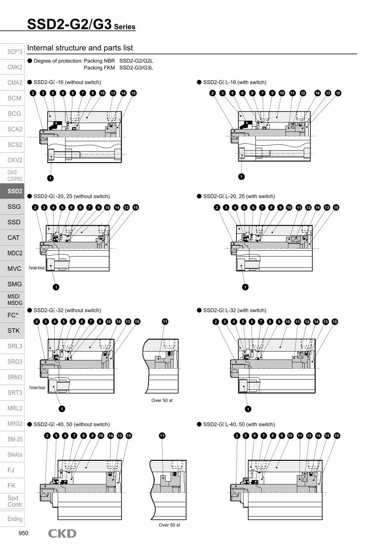
Internal structure and parts list Degree of protection: Packing NBR SSD2-G2/G2L Packing FKM SSD2-G3/G3L
SSD2-G2/G3 Series
SSD2-G23 -20, 25 (without switch) SSD2-G2
3 L-20, 25 (with switch)
SSD2-G23 -32 (without switch)
SSD2-G23 -40, 50 (without switch)
SSD2-G23 L-32 (with switch)
SSD2-G23 L-40, 50 (with switch)
SSD2-G23 -16 (without switch) SSD2-G2
3 L-16 (with switch)
2
1 1
3 4 5 6 8 7 9 10 14 13 15 2 3 4 5 6 7 8 9 10 14 13 1511 12
2 3 4 5 6 8 7 9 10 14 13 15 11 2 3 4 5 6 7 8 9 10 14 13 1511 12
2 5 6 7 8 9 10 14 13 15 11 2 5 6 7 8 9 10 14 13 1511 12
Over 50 st
Over 50 st
Female thread
Female thread
1 1
2 3 5 6 78 9 10 13 14 15
1
2 3 5 6 78 9 10 11 12 14 13 15
1
SCP*3
CMK2
CMA2
SCM
SCG
SCA2
SCS2
CKV2
CAV2/COVP/N2
SSD2
SSG
SSD
CAT
MDC2
MVC
SMG
MSD/MSDG
FC*
STK
SRL3
SRG3
SRM3
SRT3
MRL2
MRG2
SM‑25
ShkAbs
FJ
FK
SpdContr
Ending
950
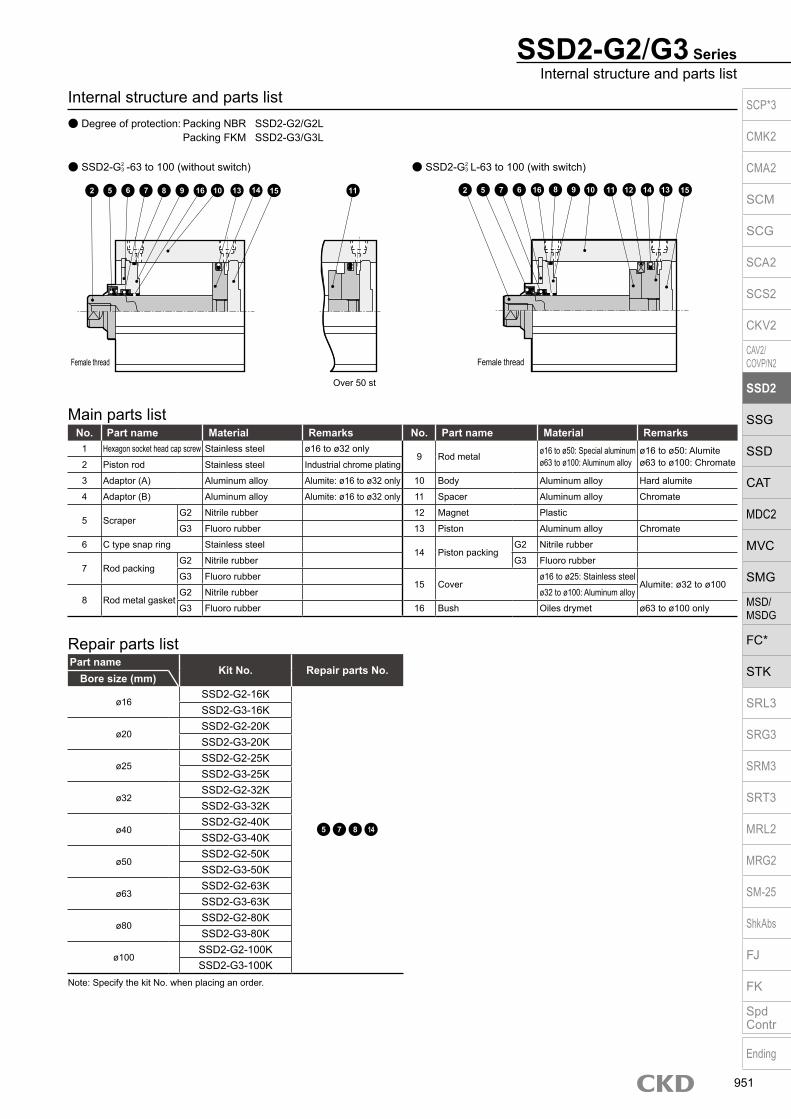
Part nameKit No. Repair parts No.
Bore size (mm)
ø16SSD2-G2-16K
5 7 8 14
SSD2-G3-16K
ø20SSD2-G2-20KSSD2-G3-20K
ø25SSD2-G2-25KSSD2-G3-25K
ø32SSD2-G2-32KSSD2-G3-32K
ø40SSD2-G2-40KSSD2-G3-40K
ø50SSD2-G2-50KSSD2-G3-50K
ø63SSD2-G2-63KSSD2-G3-63K
ø80SSD2-G2-80KSSD2-G3-80K
ø100SSD2-G2-100KSSD2-G3-100K
Repair parts list
Main parts listNo. Part name Material Remarks No. Part name Material Remarks
1 Hexagon socket head cap screw Stainless steel ø16 to ø32 only9 Rod metal ø16 to ø50: Special aluminum
ø63 to ø100: Aluminum alloyø16 to ø50: Alumiteø63 to ø100: Chromate2 Piston rod Stainless steel Industrial chrome plating
3 Adaptor (A) Aluminum alloy Alumite: ø16 to ø32 only 10 Body Aluminum alloy Hard alumite
4 Adaptor (B) Aluminum alloy Alumite: ø16 to ø32 only 11 Spacer Aluminum alloy Chromate
5 ScraperG2 Nitrile rubber 12 Magnet Plastic
G3 Fluoro rubber 13 Piston Aluminum alloy Chromate
6 C type snap ring Stainless steel14 Piston packing
G2 Nitrile rubber
7 Rod packingG2 Nitrile rubber G3 Fluoro rubber
G3 Fluoro rubber15 Cover
ø16 to ø25: Stainless steelAlumite: ø32 to ø100
8 Rod metal gasketG2 Nitrile rubber ø32 to ø100: Aluminum alloy
G3 Fluoro rubber 16 Bush Oiles drymet ø63 to ø100 only
Note: Specify the kit No. when placing an order.
SSD2-G2/G3 SeriesInternal structure and parts list
Internal structure and parts list Degree of protection: Packing NBR SSD2-G2/G2L Packing FKM SSD2-G3/G3L
SSD2-G23 -63 to 100 (without switch) SSD2-G2
3 L-63 to 100 (with switch)
2 5 6 7 8 9 16 10 13 14 15 11 5 7 6 16 8 9 10 14 13 1511 122
Over 50 st
Female thread Female thread
SCP*3
CMK2
CMA2
SCM
SCG
SCA2
SCS2
CKV2
CAV2/COVP/N2
SSD2
SSG
SSD
CAT
MDC2
MVC
SMG
MSD/MSDG
FC*
STK
SRL3
SRG3
SRM3
SRT3
MRL2
MRG2
SM‑25
ShkAbs
FJ
FK
SpdContr
Ending
951

SSD2-G2/G3 Series
Dimensions Degree of protection: Packing NBR SSD2-G2/G2L Degree of protection: Packing FKM SSD2-G3/G3L
Code Dimensions without switch Common dimensions with switchBore size (mm) A *1, *4 B *1, *4 Q A *1 B *1 Q C D EE *5 F FA FB G H I J K KA KK
ø16 35.5 27 17 40.5 32 22 15.5 5.5 M5 29 20.5 8 - - 3.5 6.5 spot face depth 3.5 (13.4) 38 M4 depth 7 M4 depth 8
ø20 39 29.5 19.5 49 39.5 29.5 18 5.5 M5 36 24.5 16 - - 5.5 9 spot face depth 5.5 (15.5) 47 M6 depth 11 M5 depth 7
ø25 42.5 32.5 22.5 52.5 42.5 32.5 21 6 M5 40 26.5 17 - - 5.5 9 spot face depth 5.5 (15.5) 51 M6 depth 11 M6 depth 12
ø32 45(55) 33(43) 23(33) 55 43 33 18 8 Rc1/8 45 29 24 49.5 12.5 5.5 9 spot face depth 5.5 (15.5) 60 M6 depth 11 M8 depth 13
ø40 46.5(56.5) 29.5(39.5) - 56.5 39.5 - 12 8.5 Rc1/8 52 32.5 31 57 15 5.5 9 spot face depth 5.5 69 M6 depth 11 M8 depth 13
ø50 48.5(58.5) 30.5(40.5) - 58.5 40.5 - 10.5 10.5 Rc1/4 64 38.5 32 71 18 6.9 11 spot face depth 6.5 86 M8 depth 13 M10 depth 15
ø63 54(64) 36(46) - 64 46 - 13 11 Rc1/4 77 45 32 84 23 8.7 14 spot face depth 9 103 M10 depth 25 M10 depth 15
ø80 63.5(73.5) 43.5(53.5) - 73.5 53.5 - 16 13 Rc3/8 98 55.5 32 104 31 10.5 17.5 spot face depth 11 132 M12 depth 28 M16 depth 21
ø100 75(85) 53(63) - 85 63 - 23 15 Rc3/8 117 65 32 123.5 38 10.5 17.5 spot face depth 11 156 M12 depth 28 M20 depth 27
Code Common dimensions with switch Proximity T2YLH,T2YLV, T3YLH, T3YLV
Dimensions of rod end male thread partBore size (mm)
M MM N O U WF a’ c’ H KK’ M MM T wfRD HD
ø16 6 8 20 - - 8.5 1.5 0 12 10 10 M6 6 8 3.6 8.5
ø20 8 10 25.5 - - 9.5 16.5 2 14 12 13 M8 8 10 5 9.5
ø25 10 12 28 - - 10 18.5 3 17.5 15 17 M10×1.25 10 12 6 10
ø32 14 16 34 4.5 - 12 19 3 23.5 20.5 22 M14×1.5 14 16 8 10
ø40 14 16 40 5 28 17 12 6.5 23.5 20.5 22 M14×1.5 14 16 8 15
ø50 17 20 50 7 35 18 12 7.5 28.5 26 27 M18×1.5 17 20 11 15
ø63 17 20 60 7 35 18 12.5 12.5 28.5 26 27 M18×1.5 17 20 11 15
ø80 22 25 77 6 43 20 15 17.5 35.5 32.5 32 M22×1.5 22 25 13 18
ø100 27 30 94 6.5 59 22 19 23 35.5 32.5 41 M26×1.5 27 30 16 18
*1 : To calculate A+ stroke length or B+ stroke length when using custom stroke length, apply the next longer standard stroke length (instead of the custom stroke length) to the stroke length value. (Example) If the custom stroke length is 7 mm, apply the standard stroke length of 10 mm.
*2 : HD and RD dimensions for 5 mm stroke length differ from these dimensions according to the setting.*3 : For dimensions of individual accessories, refer to pages 1046 to 1049.*4 : Dimensions in ( ) of codes A, B and Q are for stroke lengths of more than 50 mm.*5 : The ø32 bore size with a 5 mm stroke and without a switch has a port size of M5.*6 : Dimensions in ( ) of code J are for the spot face of rod side mounting hole.
ø20/ø25
ø32 ø40 to ø100
Rod end male thread
ø16
G F N
øK
F
0
0NH
M
FA
6-JMounting hole
øMM
FB
KK
WFA + stroke length
B + stroke length
Q + stroke length10
C DHD
2-EE
RD øI
A + stroke length
B + stroke lengthF
N
H
NF FB
MFA
øK
G
øMM
øU
WF5 C8-J mounting hole D
HD2-EE
RD øI
KK
FN
NF FBM
FAøK
6-JMounting hole
WF
A + stroke lengthB + stroke length
Q + stroke length10
C DHD 2-EE
RD
øI
øMM
KK
FN
NF
øK
6-JMounting hole
FA
FAFBM
FB
8-KA 8-KA
8-KA
a’c’T
wf
øMM
kk’Width across flats M
Width across flats H
SCP*3
CMK2
CMA2
SCM
SCG
SCA2
SCS2
CKV2
CAV2/COVP/N2
SSD2
SSG
SSD
CAT
MDC2
MVC
SMG
MSD/MSDG
FC*
STK
SRL3
SRG3
SRM3
SRT3
MRL2
MRG2
SM‑25
ShkAbs
FJ
FK
SpdContr
Ending
952

M E M OM E M OSCP*3
CMK2
CMA2
SCM
SCG
SCA2
SCS2
CKV2
CAV2/COVP/N2
SSD2
SSG
SSD
CAT
MDC2
MVC
SMG
MSD/MSDG
FC*
STK
SRL3
SRG3
SRM3
SRT3
MRL2
MRG2
SM‑25
ShkAbs
FJ
FK
SpdContr
Ending
953

Dimensions with mounting bracket Clevis bracket (CB) SSD2-G2(L)/G3(L)-16 to 100 -CB
· ø16 to ø25 · ø32 to ø100
SSD2-G2/G3 Series
Code Common dimensionsBore size
(mm)AC CA CB CC CD D E G H MR N UB
ø16 - 15 6.6 8 5 5 29 M4×12 C2 - 20 12
ø20 - 20 8.2 12 8 5 36 M6×16 C4 - 25.5 16
ø25 - 24 10.2 14 10 5 40 M6×16 C5 - 28 20
ø32 4.5 - 18.2 14 10 5 45 M6×16 - 10 34 36
ø40 5 - 18.2 14 10 6 52 M6×16 - 10 40 36
ø50 6 - 22.2 20 14 7 64 M8×20 - 14 50 44
ø63 7 - 22.2 20 14 8 77 M10×25 - 14 60 44
ø80 9 - 28.2 27 18 10 98 M12×40 - 18 77 56
ø100 12 - 32.2 31 22 13 117 M12×40 - 22 94 64
Code Female thread Male threadBore size
(mm)WF
Without switch With switcha’ wf
Without switch With switchA B CJ A B CJ A B CJ A B CJ
ø16 8.5 56.5 27 50.5 61.5 32 55.5 12 8.5 68.5 27 50.5 73.5 32 55.5
ø20 9.5 66 29.5 57 76 39.5 67 14 9.5 80 29.5 57 90 39.5 67
ø25 10 72.5 32.5 62.5 82.5 42.5 72.5 17.5 10 90 32.5 62.5 100 42.5 72.5
ø32 12 75 33 65 85 43 75 23.5 10 96.5 33 63 106.5 43 73
ø40 17 78.5 29.5 68.5 88.5 39.5 78.5 23.5 15 100 29.5 66.5 110 39.5 76.5
ø50 18 90.5 30.5 76.5 100.5 40.5 86.5 28.5 15 116 30.5 73.5 126 40.5 83.5
ø63 18 98 36 84 108 46 94 28.5 15 123.5 36 81 133.5 46 91
ø80 20 119.5 43.5 101.5 129.5 53.5 111.5 35.5 18 153 43.5 99.5 163 53.5 109.5
ø100 22 142 53 120 152 63 130 35.5 18 173.5 53 116 183.5 63 126
+ 0.2 0
+ 0.3 0
+ 0.2 0
+ 0.2 0
+ 0.2 0
+ 0.2 0
+ 0.2 0
+ 0.2 0
+ 0.2 0
NN
WF
A + stroke lengthB + stroke lengtha’ wf
A + stroke lengthRod end male thread
B + stroke lengtha’ wf
A + stroke lengthB + stroke lengthWF
Rod end male thread
A + stroke lengthB + stroke length
H
CJ + stroke lengthMounting bolt 4-C
N
E
E
CBCC
UBD
øCA
CD H10
CJ + stroke lengthCJ + stroke length
CJ + stroke length
CBCC
UBD
NE
ECD H10
Mounting bolt 4-CAC
R MR
SCP*3
CMK2
CMA2
SCM
SCG
SCA2
SCS2
CKV2
CAV2/COVP/N2
SSD2
SSG
SSD
CAT
MDC2
MVC
SMG
MSD/MSDG
FC*
STK
SRL3
SRG3
SRM3
SRT3
MRL2
MRG2
SM‑25
ShkAbs
FJ
FK
SpdContr
Ending
954

Dimensions with mounting bracket Head side flange (FB) SSD2-G2(L)/G3 (L)-20 to 100-FB
· ø16 to ø25 · ø32 to ø100
SSD2-G2/G3 SeriesDimensions with mounting bracket
Code Common dimensions Female thread Male threadBore size
(mm)FC FD FH FL FM FT G N WF
Without switch With switcha' wf
Without switch With switchA B A B A B A B
ø16 - 4.5 30 45 55 5.5 M4×12 20 8.5 41 27 46 32 12 8.5 53 27 58 32
ø20 - 6.6 39 48 60 8 M6×16 25.5 9.5 47 29.5 57 39.5 14 9.5 61 29.5 71 39.5
ø25 - 6.6 42 52 64 8 M6×16 28 10 50.5 32.5 60.5 42.5 17.5 10 68 32.5 78 42.5
ø32 34 5.5 48 56 65 8 M6×16 34 12 53 33 63 43 23.5 10 74.5 33 84.5 43
ø40 40 5.5 54 62 72 8 M6×16 40 17 54.5 29.5 64.5 39.5 23.5 15 76 29.5 86 39.5
ø50 50 6.6 67 76 89 9 M8×20 50 18 57.5 30.5 67.5 40.5 28.5 15 83 30.5 93 40.5
ø63 60 9 80 92 108 9 M10×25 60 18 63 36 73 46 28.5 15 88.5 36 98.5 46
ø80 77 11 99 116 134 11 M12×40 77 20 74.5 43.5 84.5 53.5 35.5 18 108 43.5 118 53.5
ø100 94 11 117 136 154 11 M12×40 94 22 86 53 96 63 35.5 18 117.5 53 127.5 63
N
FM
FHWF
Mounting bolt 4-GHexagon socket button head bolt
FH FC
A + stroke lengthB + stroke lengtha’ wf FT
A + stroke length
Rod end male thread
B + stroke lengtha’ wf
A + stroke lengthB + stroke lengthFL WF
FT
Rod end male thread
A + stroke length
B + stroke length FT N
2-FD
4-FDFLN
Mounting bolt 4-G
FM
FT
ø32 to ø63: Hexagon socket button head boltø80/ø100: Special bolt
SCP*3
CMK2
CMA2
SCM
SCG
SCA2
SCS2
CKV2
CAV2/COVP/N2
SSD2
SSG
SSD
CAT
MDC2
MVC
SMG
MSD/MSDG
FC*
STK
SRL3
SRG3
SRM3
SRT3
MRL2
MRG2
SM‑25
ShkAbs
FJ
FK
SpdContr
Ending
955

Compact cylinder double acting/high load/coolant proof
SSD2-KG2/KG3 Series Bore size: ø16/ø20/ø25/ø32/ø40/ø50
ø63/ø80/ø100JIS symbol
SpecificationsItem
SSD2-KG2/KG3SSD2-KG2L/KG3L (with switch)
Bore size mm ø16 ø20 ø25 ø32 ø40 ø50 ø63 ø80 ø100Actuation Double actingWorking fluid Compressed airMax. working pressure MPa 1.0 (≈150 psi, 10 bar)Min. working pressure MPa 0.15 (≈22 psi, 1.5 bar) 0.1 (≈15 psi, 1 bar)Proof pressure MPa 1.6 (≈230 psi, 16 bar)Ambient temperature °C -10 (14°F) to 60 (140°F) (no freezing)Port size M5×0.8 Rc1/8 Rc1/4 Rc3/8Stroke tolerance mm +2.0
0
Working piston speed mm/s 50 to 500 50 to 300Cushion Rubber cushionLubrication Not required (use turbine oil class 1 ISO VG32 if necessary for lubrication)Allowable absorbed energy J 0.09 0.16 0.16 0.4 0.63 0.98 1.56 2.51 3.92
Custom stroke length SSD2-KG2/KG3 Series
ItemStandard products
Standard stroke length body with spacerModel No. Refer to How to order.
DescriptionA spacer is added to the standard stroke length body to adjust the stroke length in 1 mm increments.
Stroke range
Bore size Stroke range16 1 to 29
20 to 25 1 to 4932 to 100 1 to 99
Example of model No.
Model No.: SSD2-KG2-32-41A +4 mm spacer is added to the SSD2-KG2-32-45 standard cylinder to create 41 mm stroke length.B + stroke length is 88 mm.
Stroke lengthBore size (mm) Standard stroke length (mm) Max. stroke length (mm) Min. stroke length (mm)
ø16 5/10/15/20/25/30 30
1(10)The value in ( ) is for types with one or two switches.
ø20 5/10/15/20/25/ 30/35/40/45/50
50ø25ø32 5/10/15/20/25/30/
35/40/45/50/75/100100
ø40ø50
10/15/20/25/ 30/35/40/45/ 50/75/100
100ø63ø80ø100
*1: The custom stroke length is available in 1 mm increments. (Less than 10 mm with switch is not available.) However, the total length is the same as that of the next longer standard stroke length.
A + stroke length
B + stroke length
SCP*3
CMK2
CMA2
SCM
SCG
SCA2
SCS2
CKV2
CAV2/COVP/N2
SSD2
SSG
SSD
CAT
MDC2
MVC
SMG
MSD/MSDG
FC*
STK
SRL3
SRG3
SRM3
SRT3
MRL2
MRG2
SM‑25
ShkAbs
FJ
FK
SpdContr
Ending
956

SSD2-KG2/KG3 SeriesSpecifications
Switch specifications Proximity switchType/model No. Proximity/2-wire Proximity/3-wire
Item T2YLH/T2YLV T3YLH/T3YLVApplications Dedicated for programmable controller Programmable controller, relayPower supply voltage - 10 to 28 VDCLoad voltage/current 10 to 30 VDC, 5 to 20 mA *1 30 VDC or less, 50 mA or lessIndicator lamp Red/green LED (Lit when ON)Leakage current 1 mA or less 10 μA or lessMax. shock resistance 980 m/S2
Weight g 1 m:33 3 m:87 5 m:142*1 : The above max. load current is 20 mA at 25°C. The current is lower than 20 mA if the operating ambient temperature around the switch is higher than 25˚C. (5 to 10 mA at 60˚C)*2 : Refer to Ending Page 1 for other switch specifications.
Bore size (mm)
Operating direction
Working pressure MPa0.1 0.15 0.2 0.3 0.4 0.5 0.6 0.7 0.8 0.9 1.0
ø16Push - 30.2 40.2 60.3 80.4 1.01×10² 1.21×10² 1.41×10² 1.61×10² 1.81×10² 2.01×10²
Pull - 22.6 30.2 45.2 60.3 75.4 90.5 1.06×10² 1.21×10² 1.36×10² 1.51×10²
ø20Push - 47.1 62.8 94.2 1.26×10² 1.57×10² 1.88×10² 2.20×10² 2.51×10² 2.83×10² 3.14×10²
Pull - 35.3 47.1 70.7 94.2 1.18×10² 1.41×10² 1.65×10² 1.88×10² 2.12×10² 2.36×10²
ø25Push - 73.6 98.2 1.47×10² 1.96×10² 2.45×10² 2.95×10² 3.44×10² 3.93×10² 4.42×10² 4.91×10²
Pull - 56.7 75.6 1.13×10² 1.51×10² 1.89×10² 2.27×10² 2.64×10² 3.02×10² 3.40×10² 3.78×10²
ø32Push - 1.21×10² 1.61×10² 2.41×10² 3.22×10² 4.02×10² 4.83×10² 5.63×10² 6.43×10² 7.24×10² 8.04×10²
Pull - 90.5 1.21×10² 1.81×10² 2.41×10² 3.02×10² 3.62×10² 4.22×10² 4.83×10² 5.43×10² 6.03×10²
ø40Push - 1.88×10² 2.51×10² 3.77×10² 5.03×10² 6.28×10² 7.54×10² 8.80×10² 1.01×10³ 1.13×10³ 1.26×10³
Pull - 1.58×10² 2.11×10² 3.17×10² 4.22×10² 5.28×10² 6.33×10² 7.39×10² 8.44×10² 9.50×10² 1.06×10³
ø50Push - 2.95×10² 3.93×10² 5.89×10² 7.85×10² 9.82×10² 1.18×10³ 1.37×10³ 1.57×10³ 1.77×10³ 1.96×10³
Pull - 2.47×10² 3.30×10² 4.95×10² 6.60×10² 8.25×10² 9.90×10² 1.15×10³ 1.32×10³ 1.48×10³ 1.65×10³
ø63Push 3.12×10² 4.68×10² 6.23×10² 9.35×10² 1.25×10³ 1.56×10³ 1.87×10³ 2.18×10³ 2.49×10³ 2.81×10³ 3.12×10³
Pull 2.80×10² 4.20×10² 5.61×10² 8.41×10² 1.12×10³ 1.40×10³ 1.68×10³ 1.96×10³ 2.24×10³ 2.52×10³ 2.80×10³
ø80Push 5.03×10² 7.54×10² 1.01×10³ 1.51×10³ 2.01×10³ 2.51×10³ 3.02×10³ 3.52×10³ 4.02×10³ 4.52×10³ 5.03×10³
Pull 4.54×10² 6.80×10² 9.07×10² 1.36×10³ 1.81×10³ 2.27×10³ 2.72×10³ 3.17×10³ 3.63×10³ 4.08×10³ 4.54×10³
ø100Push 7.85×10² 1.18×10³ 1.57×10³ 2.36×10³ 3.14×10³ 3.93×10³ 4.71×10³ 5.50×10³ 6.28×10³ 7.07×10³ 7.85×10³
Pull 7.15×10² 1.07×10³ 1.43×10³ 2.14×10³ 2.86×10³ 3.57×10³ 4.29×10³ 5.00×10³ 5.72×10³ 6.43×10³ 7.15×10³
Theoretical thrust table (Unit: N)
Stroke length (mm) 5 10 15 20 25 30 35 40 45 50 75 100Bore size (mm) No switch Switch No switch Switch No switch Switch No switch Switch No switch Switch No switch Switch No switch Switch No switch Switch No switch Switch No switch Switch No switch Switch No switch Switch
ø16 69 114 79 124 90 135 101 146 112 157 123 168 - - - - - - - - - - - -ø20 68 163 101 176 114 189 126 201 139 214 151 226 164 239 176 251 189 264 201 276 - - - -ø25 118 209 134 225 150 241 166 257 181 272 198 289 214 305 230 321 246 337 262 353 - - - -ø32 211 325 232 346 253 367 275 389 297 411 319 433 341 455 362 476 384 498 405 519 513 627 620 734ø40 289 432 316 459 343 486 369 512 395 538 422 565 449 592 475 618 502 645 528 671 661 804 793 936ø50 - - 509 703 551 745 594 788 637 831 678 872 720 914 762 956 804 998 846 1040 1056 1250 1266 1460ø63 - - 727 1006 782 1061 837 1116 893 1172 948 1227 1003 1282 1058 1337 1113 1392 1168 1447 1443 1722 1718 1997ø80 - - 1274 1687 1361 1774 1447 1860 1534 1947 1621 2034 1708 2121 1794 2207 1881 2294 1967 2380 2400 2813 2832 3245
ø100 - - 1887 2454 2001 2568 2115 2682 2229 2796 2342 2909 2456 3023 2570 3137 2684 3251 2798 3365 3368 3935 3938 4505
Cylinder weight table (the weight of the switches is when there are 2 cylinder switches.) (Unit: g)
SCP*3
CMK2
CMA2
SCM
SCG
SCA2
SCS2
CKV2
CAV2/COVP/N2
SSD2
SSG
SSD
CAT
MDC2
MVC
SMG
MSD/MSDG
FC*
STK
SRL3
SRG3
SRM3
SRT3
MRL2
MRG2
SM‑25
ShkAbs
FJ
FK
SpdContr
Ending
957
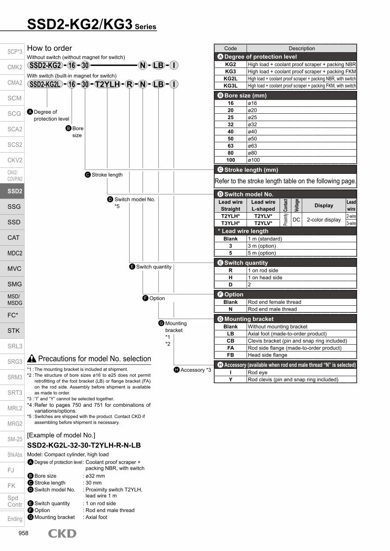
SSD2-KG2/KG3 Series
Precautions for model No. selection*1 : The mounting bracket is included at shipment.*2 : The structure of bore sizes ø16 to ø25 does not permit
retrofitting of the foot bracket (LB) or flange bracket (FA) on the rod side. Assembly before shipment is available as made to order.
*3 : “I” and “Y” cannot be selected together.*4 : Refer to pages 750 and 751 for combinations of
variations/options.*5 : Switches are shipped with the product. Contact CKD if
assembling before shipment is necessary.
[Example of model No.]SSD2-KG2L-32-30-T2YLH-R-N-LBModel: Compact cylinder, high loadA Degree of protection level : Coolant proof scraper +
packing NBR, with switchB Bore size : ø32 mmC Stroke length : 30 mmD Switch model No. : Proximity switch T2YLH,
lead wire 1 mE Switch quantity : 1 on rod sideF Option : Rod end male threadG Mounting bracket : Axial foot
Accessory *3H
How to orderWithout switch (without magnet for switch)
With switch (built-in magnet for switch)
16 IN30
Mounting bracket *1*2
G
D
Bore size
B
Stroke lengthC
Switch model No.*5
Switch quantityE
OptionF
16 R IN30
Code DescriptionDegree of protection levelKG2 High load + coolant proof scraper + packing NBRKG3 High load + coolant proof scraper + packing FKM
KG2L High load + coolant proof scraper + packing NBR, with switchKG3L High load + coolant proof scraper + packing FKM, with switch
Bore size (mm)16 ø1620 ø2025 ø2532 ø3240 ø4050 ø5063 ø6380 ø80100 ø100
Stroke length (mm)
Refer to the stroke length table on the following page.
* Lead wire lengthBlank 1 m (standard)
3 3 m (option)5 5 m (option)
Switch quantityR 1 on rod sideH 1 on head sideD 2
OptionBlank Rod end female thread
N Rod end male thread
Mounting bracketBlank Without mounting bracket
LB Axial foot (made-to-order product)CB Clevis bracket (pin and snap ring included)FA Rod side flange (made-to-order product)FB Head side flange
Accessory (available when rod end male thread “N” is selected)I Rod eyeY Rod clevis (pin and snap ring included)
A
B
C
E
F
H
G
Switch model No.Lead wire Lead wire
Conta
ct
Volta
ge
Display Lead wireStraight L-shaped
T2YLH* T2YLV*
Proxim
ity
DC 2-color display2-wire
T3YLH* T2YLV* 3-wire
D
Degree of protection level
A
SSD2-KG2
SSD2-KG2L
LB
LBT2YLH
SCP*3
CMK2
CMA2
SCM
SCG
SCA2
SCS2
CKV2
CAV2/COVP/N2
SSD2
SSG
SSD
CAT
MDC2
MVC
SMG
MSD/MSDG
FC*
STK
SRL3
SRG3
SRM3
SRT3
MRL2
MRG2
SM‑25
ShkAbs
FJ
FK
SpdContr
Ending
958

SSD2-KG2/KG3 SeriesHow to order
How to order switch
Switch model No. (Item D on page 958)
*1 : Less than 10 mm stroke length is not available. Refer to page 956 for the number of installed switches and the min. stroke length.*2 : The total length is the same as that of the next longer standard stroke length.
Bore size (mm)ø16 ø20 ø25 ø32 ø40 ø50 ø63 ø80 ø100
Mounting bracketFoot (LB) SSD2-LB-40 SSD2-LB-50 SSD2-LB-63 SSD2-LB-80 SSD2-LB-100Flange (FA/FB) SSD2-FA-40 SSD2-FA-50 SSD2-FA-63 SSD2-FA-80 SSD2-FA-100Clevis bracket (CB) SSD2-CB-16 SSD2-CB-20 SSD2-CB-25 SSD2-CB-32 SSD2-CB-40 SSD2-CB-50 SSD2-CB-63 SSD2-CB-80 SSD2-CB-100
How to order mounting bracket
*1: The foot mounting bracket is provided as 2 pcs./set.*2: The structure of bore sizes ø16 to ø25 does not permit retrofitting of the foot bracket (LB) or flange bracket (FA) on the rod side. Contact CKD for details.
Stroke length (mm)Applicable bore size
16 20 25 32 40 50 63 80 100
Sta
ndar
d st
roke
leng
th
5 10 15 20 25 30 35 40 45 50 75
100 Min. stroke length (mm) *1 1Max. stroke length (mm) 30 50 100Custom stroke length *2
[Stroke length table]
T2YLHSWSCP*3
CMK2
CMA2
SCM
SCG
SCA2
SCS2
CKV2
CAV2/COVP/N2
SSD2
SSG
SSD
CAT
MDC2
MVC
SMG
MSD/MSDG
FC*
STK
SRL3
SRG3
SRM3
SRT3
MRL2
MRG2
SM‑25
ShkAbs
FJ
FK
SpdContr
Ending
959

SSD2-KG2/KG3 Series
Internal structure and parts list Degree of protection: Packing NBR SSD2-KG2/KG2L Degree of protection: Packing FKM SSD2-KG3/KG3L
SSD2-KG23 L-16 (with switch) SSD2-KG2
3 L-20, 25 (with switch) SSD2-KG23 L-32 to 50 (with switch)
SSD2-KG23 L-63 to 100 (with switch) SSD2-KG2
3 -16 (without switch) SSD2-KG23 -20, 25 (without switch)
SSD2-KG23 -32 to 50 (without switch) SSD2-KG2
3 -63 to 100 (without switch)
6 9 12 8 11 13 14 15 1617
2 5 7 10
18 19
3 3 4 6 9 8 11 13 16 18 1912 14 15
2 5 1 7 10
6 8 11 12 13 14 15 16 18 19
2 1 5 9 7
4 3 6 9 8 12 14 16 18 1913 15 1711
2 1 5 10 7
6 3 3 4 6 9 10 11 12 15 17 18 198 16
2 1 5 7
6 8 11 12 15 17 16 18 19
2 1 5 9 7
9 8 12 11 17 15 16 18 19
2 5 7 10
4 3 6 9 8 12 11 15 17 16 18 19
2 1 5 10 7
SCP*3
CMK2
CMA2
SCM
SCG
SCA2
SCS2
CKV2
CAV2/COVP/N2
SSD2
SSG
SSD
CAT
MDC2
MVC
SMG
MSD/MSDG
FC*
STK
SRL3
SRG3
SRM3
SRT3
MRL2
MRG2
SM‑25
ShkAbs
FJ
FK
SpdContr
Ending
960

Part nameKit No. Repair parts No.
Bore size (mm)
ø16SSD2-KG2-16K
5 7 8 12
15 16 18
SSD2-KG3-16K
ø20SSD2-KG2-20KSSD2-KG3-20K
ø25SSD2-KG2-25KSSD2-KG3-25K
ø32SSD2-KG2-32KSSD2-KG3-32K
ø40SSD2-KG2-40KSSD2-KG3-40K
ø50SSD2-KG2-50KSSD2-KG3-50K
ø63SSD2-KG2-63KSSD2-KG3-63K
ø80SSD2-KG2-80KSSD2-KG3-80K
ø100SSD2-KG2-100KSSD2-KG3-100K
Repair parts list
Main parts listNo. Part name Material Remarks No. Part name Material Remarks
1 Hexagon socket head cap screw Stainless steel ø16 to ø25 only 10 Bush Oiles drymet ø20 to ø100 only
2 Piston rod Stainless steel Industrial chrome plating 11 Body Aluminum alloy Hard alumite
3 Adaptor (A) Aluminum alloy Alumite: ø16 to ø25 only 12 Cushion rubber R Urethane rubber
4 Adaptor (B) Aluminum alloy Alumite: ø20/ø25 only 13 Spacer Aluminum alloy ø16 to ø32: Chromate
5 ScraperG2 Nitrile rubber 14 Magnet Plastic
G3 Fluoro rubber15 Piston packing
G2 Nitrile rubber
6 C type snap ring (for hole) Stainless steel G3 Fluoro rubber
7 Rod packingG2 Nitrile rubber 16 Wear ring Polyacetal resin
G3 Fluoro rubber 17 Piston Aluminum alloy Chromate
8 Rod metal gasketG2 Nitrile rubber 18 Cushion rubber H Urethane rubber
G3 Fluoro rubber19 Cover ø16 to ø25: Stainless steel
ø32 to ø100: Aluminum alloy Alumite9 Rod metal Aluminum alloy Alumite
Note: Specify the kit No. when placing an order.
SSD2-KG2/KG3 SeriesInternal structure and parts list
SCP*3
CMK2
CMA2
SCM
SCG
SCA2
SCS2
CKV2
CAV2/COVP/N2
SSD2
SSG
SSD
CAT
MDC2
MVC
SMG
MSD/MSDG
FC*
STK
SRL3
SRG3
SRM3
SRT3
MRL2
MRG2
SM‑25
ShkAbs
FJ
FK
SpdContr
Ending
961

SSD2-KG2/KG3 Series
Dimensions Degree of protection: Packing NBR SSD2-KG/KG2L Degree of protection: Packing FKM SSD2-KG3/KG3L
Code Dimensions without switch Common dimensions with switchBore size (mm) A *1 B *1 Q *1 A *1 B *1 Q *1 C D EE F FA FB G H I J K KA KK
ø16 40.5 32 22 45.5 37 27 15.5 5.5 M5 29 21 8 - - 3.5 6.5 spot face depth 3.5 (13.4) 38 M4 depth 7 M4 depth 8
ø20 44 34.5 24.5 54 44.5 34.5 18 5.5 M5 36 24.5 16 - - 5.5 9 spot face depth 5.5 (15.5) 47 M6 depth 11 M5 depth 7
ø25 47.5 37.5 27.5 57.5 47.5 37.5 21 6 M5 40 26.5 17 - - 5.5 9 spot face depth 5.5 (15.5) 51 M6 depth 11 M6 depth 12
ø32 55(65) 43(53) 33(43) 65 53 43 18 8 Rc1/8 45 29 24 49.5 12.5 5.5 9 spot face depth 5.5 (15.5) 60 M6 depth 11 M8 depth 13
ø40 56.5(66.5) 39.5(49.5) - 66.5 49.5 - 12 8.5 Rc1/8 52 32.5 31 57 15 5.5 ø9 spot face depth 5.5 69 M6 depth 11 M8 depth 13
ø50 58.5(68.5) 40.5(50.5) - 68.5 50.5 - 10.5 10.5 Rc1/4 64 38.5 32 71 18 6.9 ø11 spot face depth 6.5 86 M8 depth 13 M10 depth 15
ø63 64(74) 46(56) - 74 56 - 13 11 Rc1/4 77 45 32 84 23 8.7 ø14 spot face depth 9 103 M10 depth 25 M10 depth 15
ø80 73.5(83.5) 53.5(63.5) - 83.5 63.5 - 16 13 Rc3/8 98 55.5 32 104 31 10.5 ø17.5 spot face depth 11 132 M12 depth 28 M16 depth 21
ø100 85(95) 63(73) - 95 73 - 23 15 Rc3/8 117 65 32 123.5 38 10.5 ø17.5 spot face depth 11 156 M12 depth 28 M20 depth 27
Code Common dimensions with switch Proximity T2YLH, T2YLV, T3YLH, T3YLV
Dimensions of rod end male thread partBore size (mm)
M MM N O U WF a’ c’ H KK’ M MM T wfHD RD
ø16 6 8 20 - - 8.5 2.5 14.5 12 10 10 M6 6 8 3.6 8.5
ø20 8 10 25.5 - - 9.5 4.5 20.0 14 12 13 M8 8 10 5 9.5
ø25 10 12 28 - - 10 4.5 22.5 17.5 15 17 M10×1.25 10 12 6 10
ø32 14 16 34 4.5 - 12 9.5 25.5 23.5 20.5 22 M14×1.5 14 16 8 10
ø40 14 16 40 5 28 17 10.5 31.0 23.5 20.5 22 M14×1.5 14 16 8 15
ø50 17 20 50 7 35 18 11.5 31.0 28.5 26 27 M18×1.5 17 20 11 15
ø63 17 20 60 7 35 18 18.0 29.0 28.5 26 27 M18×1.5 17 20 11 15
ø80 22 25 77 6 43 20 24.0 31.5 35.5 32.5 32 M22×1.5 22 25 13 18
ø100 27 30 94 6.5 59 22 29.5 35.5 35.5 32.5 41 M26×1.5 27 30 16 18
*1 : To calculate A+ stroke length or B+ stroke length when using custom stroke length, apply the next longer standard stroke length (instead of the custom stroke length) to the stroke length value. (Example) If the custom stroke length is 7 mm, apply the standard stroke length of 10 mm.
*2 : HD and RD dimensions for 5 mm stroke length differ from these dimensions according to the setting.*3 : For dimensions of individual accessories, refer to pages 1046 to 1049.*4 : Dimensions in ( ) of codes A and B are for stroke lengths of more than 50 mm.*5 : Dimensions in ( ) of code J are for the spot face of rod side mounting hole.
ø20/ø25
ø32 ø40 to ø100
Rod end male thread
ø16øM
M
KK
WFA + stroke length
B + stroke length
Q + stroke length10
C DHD
2-EE
RD øI
A + stroke length
B + stroke length
øMM
øU
WF5 C D
HD2-EE
RD øI
KK
FN
NF FBM
FAøK
6-JMounting hole
WF
A + stroke lengthB + stroke length
Q + stroke length10
C DHD 2-EE
RD
øI
øMM
KK
FN
NF
øK
6-JMounting hole
FA
FAFBM
FB
8-KA 8-KA
8-KA
a’c’T
wf
øMM
kk’Width across flats M
Width across flats H
G FO
N
øK
FNH
M
FA
6-JMounting hole
FB
O
F
N
H
NF FB
MFA
øK
G
8-JMounting hole
SCP*3
CMK2
CMA2
SCM
SCG
SCA2
SCS2
CKV2
CAV2/COVP/N2
SSD2
SSG
SSD
CAT
MDC2
MVC
SMG
MSD/MSDG
FC*
STK
SRL3
SRG3
SRM3
SRT3
MRL2
MRG2
SM‑25
ShkAbs
FJ
FK
SpdContr
Ending
962

M E M OM E M OSCP*3
CMK2
CMA2
SCM
SCG
SCA2
SCS2
CKV2
CAV2/COVP/N2
SSD2
SSG
SSD
CAT
MDC2
MVC
SMG
MSD/MSDG
FC*
STK
SRL3
SRG3
SRM3
SRT3
MRL2
MRG2
SM‑25
ShkAbs
FJ
FK
SpdContr
Ending
963

Dimensions with mounting bracket Clevis bracket (CB) SSD2-KG2(L)/KG3(L)-20 to 100 -CB
· ø16 to ø25 · ø32 to ø100
SSD2-KG2/KG3 Series
Code Common dimensionsBore size
(mm)AC CA CB CC CD D E G H MR N UB
ø16 - 15 6.6 8 5 5 29 M4×12 C2 - 20 12
ø20 - 20 8.2 12 8 5 36 M6×16 C4 - 25.5 16
ø25 - 24 10.2 14 10 5 40 M6×16 C5 - 28 20
ø32 4.5 - 18.2 14 10 5 45 M6×16 - 10 34 36
ø40 5 - 18.2 14 10 6 52 M6×16 - 10 40 36
ø50 6 - 22.2 20 14 7 64 M8×20 - 14 50 44
ø63 7 - 22.2 20 14 8 77 M10×25 - 14 60 44
ø80 9 - 28.2 27 18 10 98 M12×40 - 18 77 56
ø100 12 - 32.2 31 22 13 117 M12×40 - 22 94 64
Code Female thread Male threadBore size
(mm)WF
Without switch With switcha’ wf
Without switch With switchA B CJ A B CJ A B CJ A B CJ
ø16 8.5 61.5 32 55.5 66.5 37 60.5 12 8.5 73.5 32 55.5 78.5 37 60.5
ø20 9.5 71 34.5 62 81 44.5 72 14 9.5 85 34.5 62 95 44.5 72
ø25 10 77.5 37.5 67.5 87.5 47.5 77.5 17.5 10 95 37.5 67.5 105 47.5 77.5
ø32 12 85 43 75 95 53 85 23.5 10 106.5 43 73 116.5 53 83
ø40 17 88.5 39.5 78.5 98.5 49.5 88.5 23.5 15 110 39.5 76.5 120 49.5 86.5
ø50 18 100.5 40.5 86.5 110.5 50.5 96.5 28.5 15 126 40.5 83.5 136 50.5 93.5
ø63 18 108 46 94 118 56 104 28.5 15 133.5 46 91 143.5 56 101
ø80 20 129.5 53.5 111.5 139.5 63.5 121.5 35.5 18 163 53.5 109.5 173 63.5 119.5
ø100 22 152 63 130 162 73 140 35.5 18 183.5 63 126 193.5 73 136
+ 0.3 0
+ 0.2 0
+ 0.2 0
+ 0.2 0
+ 0.2 0
+ 0.2 0
+ 0.2 0
+ 0.2 0
+ 0.2 0
NN
WF
A + stroke lengthB + stroke lengtha’ wf
A + stroke lengthRod end male thread
B + stroke lengtha’ wf
A + stroke lengthB + stroke lengthWF
Rod end male thread
A + stroke lengthB + stroke length
H
CJ + stroke lengthMounting bolt 4-C
N
E
E
CBCC
UBD
øCA
CD H10
CJ + stroke lengthCJ + stroke length
CJ + stroke length
CBCC
UBD
NE
ECD H10
Mounting bolt 4-CAC
R MR
SCP*3
CMK2
CMA2
SCM
SCG
SCA2
SCS2
CKV2
CAV2/COVP/N2
SSD2
SSG
SSD
CAT
MDC2
MVC
SMG
MSD/MSDG
FC*
STK
SRL3
SRG3
SRM3
SRT3
MRL2
MRG2
SM‑25
ShkAbs
FJ
FK
SpdContr
Ending
964
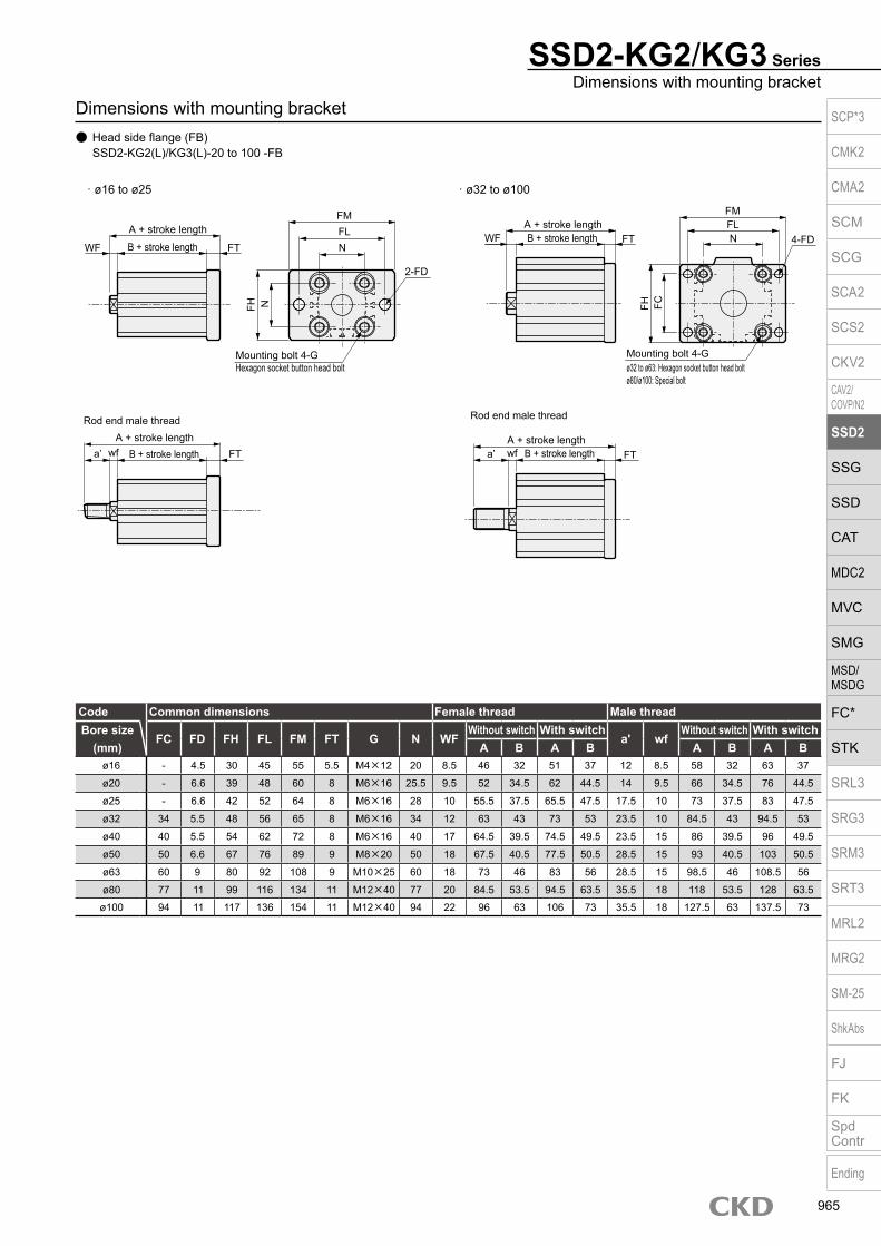
Dimensions with mounting bracket Head side flange (FB) SSD2-KG2(L)/KG3(L)-20 to 100 -FB
· ø16 to ø25 · ø32 to ø100
SSD2-KG2/KG3 SeriesDimensions with mounting bracket
Code Common dimensions Female thread Male threadBore size
(mm)FC FD FH FL FM FT G N WF
Without switch With switcha' wf
Without switch With switchA B A B A B A B
ø16 - 4.5 30 45 55 5.5 M4×12 20 8.5 46 32 51 37 12 8.5 58 32 63 37
ø20 - 6.6 39 48 60 8 M6×16 25.5 9.5 52 34.5 62 44.5 14 9.5 66 34.5 76 44.5
ø25 - 6.6 42 52 64 8 M6×16 28 10 55.5 37.5 65.5 47.5 17.5 10 73 37.5 83 47.5
ø32 34 5.5 48 56 65 8 M6×16 34 12 63 43 73 53 23.5 10 84.5 43 94.5 53
ø40 40 5.5 54 62 72 8 M6×16 40 17 64.5 39.5 74.5 49.5 23.5 15 86 39.5 96 49.5
ø50 50 6.6 67 76 89 9 M8×20 50 18 67.5 40.5 77.5 50.5 28.5 15 93 40.5 103 50.5
ø63 60 9 80 92 108 9 M10×25 60 18 73 46 83 56 28.5 15 98.5 46 108.5 56
ø80 77 11 99 116 134 11 M12×40 77 20 84.5 53.5 94.5 63.5 35.5 18 118 53.5 128 63.5
ø100 94 11 117 136 154 11 M12×40 94 22 96 63 106 73 35.5 18 127.5 63 137.5 73
N
FM
FHWF
Mounting bolt 4-GHexagon socket button head bolt
FH FC
A + stroke lengthB + stroke lengtha’ wf FT
A + stroke length
Rod end male thread
B + stroke lengtha’ wf
A + stroke lengthB + stroke lengthFL WF
FT
Rod end male thread
A + stroke length
B + stroke length FT N
2-FD
4-FDFLN
Mounting bolt 4-G
FM
FT
ø32 to ø63: Hexagon socket button head boltø80/ø100: Special bolt
SCP*3
CMK2
CMA2
SCM
SCG
SCA2
SCS2
CKV2
CAV2/COVP/N2
SSD2
SSG
SSD
CAT
MDC2
MVC
SMG
MSD/MSDG
FC*
STK
SRL3
SRG3
SRM3
SRT3
MRL2
MRG2
SM‑25
ShkAbs
FJ
FK
SpdContr
Ending
965
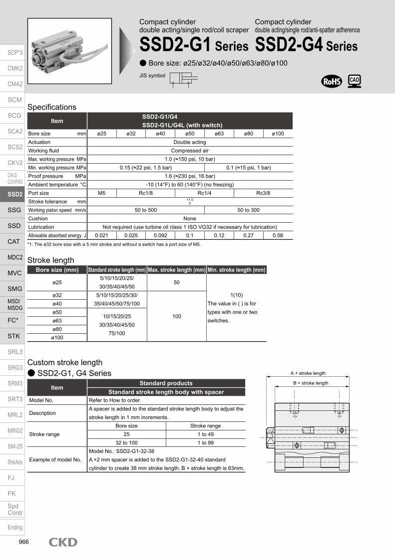
Compact cylinderdouble acting/single rod/coil scraper
SSD2-G1 Series Bore size: ø25/ø32/ø40/ø50/ø63/ø80/ø100
SpecificationsItem
SSD2-G1/G4SSD2-G1L/G4L (with switch)
Bore size mm ø25 ø32 ø40 ø50 ø63 ø80 ø100Actuation Double actingWorking fluid Compressed airMax. working pressure MPa 1.0 (≈150 psi, 10 bar)Min. working pressure MPa 0.15 (≈22 psi, 1.5 bar) 0.1 (≈15 psi, 1 bar)Proof pressure MPa 1.6 (≈230 psi, 16 bar)Ambient temperature °C -10 (14°F) to 60 (140°F) (no freezing)Port size M5 Rc1/8 Rc1/4 Rc3/8Stroke tolerance mm +1.0
0
Working piston speed mm/s 50 to 500 50 to 300Cushion NoneLubrication Not required (use turbine oil class 1 ISO VG32 if necessary for lubrication)Allowable absorbed energy J 0.021 0.025 0.092 0.1 0.12 0.27 0.56
JIS symbol
Stroke lengthBore size (mm) Standard stroke length (mm) Max. stroke length (mm) Min. stroke length (mm)
ø255/10/15/20/25/ 30/35/40/45/50
50
1(10)The value in ( ) is for types with one or two switches.
ø32 5/10/15/20/25/30/35/40/45/50/75/100
100
ø40ø50
10/15/20/2530/35/40/45/50
75/100
ø63ø80ø100
Custom stroke length SSD2-G1, G4 Series
ItemStandard products
Standard stroke length body with spacerModel No. Refer to How to order.
DescriptionA spacer is added to the standard stroke length body to adjust the stroke length in 1 mm increments.
Stroke rangeBore size Stroke range
25 1 to 4932 to 100 1 to 99
Example of model No.Model No.: SSD2-G1-32-38A +2 mm spacer is added to the SSD2-G1-32-40 standard cylinder to create 38 mm stroke length. B + stroke length is 63mm.
*1: The ø32 bore size with a 5 mm stroke and without a switch has a port size of M5.
Compact cylinderdouble acting/single rod/anti-spatter adherence
SSD2-G4 Series
A + stroke length
B + stroke length
SCP*3
CMK2
CMA2
SCM
SCG
SCA2
SCS2
CKV2
CAV2/COVP/N2
SSD2
SSG
SSD
CAT
MDC2
MVC
SMG
MSD/MSDG
FC*
STK
SRL3
SRG3
SRM3
SRT3
MRL2
MRG2
SM‑25
ShkAbs
FJ
FK
SpdContr
Ending
966

SSD2-G1/G4 SeriesSpecifications
Switch specifications
ItemProximity 2-wire
T2YD/T2YDTApplications Dedicated for programmable controllerIndicator lamp Red/green LED (Lit when ON)Load voltage 24 VDC ±10%Load current 5 to 20 VDCInternal voltage drop 6V or lessLeakage current 1.0 mA or lessOutput delay time *1(Delay ON, delay OFF)
60 ms or less
Lead wire length1 m (oil resistant vinyl cabtyre cableø 6, 0.5 mm2 x 2-conductor) *2, *3
Insulation resistance 100 MΩ and over with 500 VDC meggerWithstand voltage No failure after 1 minute of 1,000 VAC application.Max. shock resistance 980 m/s2
Ambient temperature -10 to +60°CDegree of protection JIS C0920 (water-tight), IEC standards IP67, oil resistanceWeight g 1 m:61 3 m:166 5 m:272*1: Indicates the time from magnetic sensor detection of the piston magnet until switch output.*2: 3 m and 5 m lead wires are available as options.*3: Flame-resistant lead wires are available as options.*4: This switch cannot be used in DC environments.
Bore size (mm)
Operating direction
Working pressure MPa0.1 0.15 0.2 0.3 0.4 0.5 0.6 0.7 0.8 0.9 1.0
ø25Push - 73.6 98.2 1.47×10² 1.96×10² 2.45×10² 2.95×10² 3.44×10² 3.93×10² 4.42×10² 4.91×10²
Pull - 56.7 75.6 1.13×10² 1.51×10² 1.89×10² 2.27×10² 2.64×10² 3.02×10² 3.40×10² 3.78×10²
ø32Push - 1.21×10² 1.61×10² 2.41×10² 3.22×10² 4.02×10² 4.83×10² 5.63×10² 6.43×10² 7.24×10² 8.04×10²
Pull - 90.5 1.21×10² 1.81×10² 2.41×10² 3.02×10² 3.62×10² 4.22×10² 4.83×10² 5.43×10² 6.03×10²
ø40Push - 1.88×10² 2.51×10² 3.77×10² 5.03×10² 6.28×10² 7.54×10² 8.80×10² 1.01×10³ 1.13×10³ 1.26×10³
Pull - 1.58×10² 2.11×10² 3.17×10² 4.22×10² 5.28×10² 6.33×10² 7.39×10² 8.44×10² 9.50×10² 1.06×10³
ø50Push - 2.95×10² 3.93×10² 5.89×10² 7.85×10² 9.82×10² 1.18×10³ 1.37×10³ 1.57×10³ 1.77×10³ 1.96×10³
Pull - 2.47×10² 3.30×10² 4.95×10² 6.60×10² 8.25×10² 9.90×10² 1.15×10³ 1.32×10³ 1.48×10³ 1.65×10³
ø63Push 3.12×10² 4.68×10² 6.23×10² 9.35×10² 1.25×10³ 1.56×10³ 1.87×10³ 2.18×10³ 2.49×10³ 2.81×10³ 3.12×10³
Pull 2.80×10² 4.20×10² 5.61×10² 8.41×10² 1.12×10³ 1.40×10³ 1.68×10³ 1.96×10³ 2.24×10³ 2.52×10³ 2.80×10³
ø80Push 5.03×10² 7.54×10² 1.01×10³ 1.51×10³ 2.01×10³ 2.51×10³ 3.02×10³ 3.52×10³ 4.02×10³ 4.52×10³ 5.03×10³
Pull 4.54×10² 6.80×10² 9.07×10² 1.36×10³ 1.81×10³ 2.27×10³ 2.72×10³ 3.17×10³ 3.63×10³ 4.08×10³ 4.54×10³
ø100Push 7.85×10² 1.18×10³ 1.57×10³ 2.36×10³ 3.14×10³ 3.93×10³ 4.71×10³ 5.50×10³ 6.28×10³ 7.07×10³ 7.85×10³
Pull 7.15×10² 1.07×10³ 1.43×10³ 2.14×10³ 2.86×10³ 3.57×10³ 4.29×10³ 5.00×10³ 5.72×10³ 6.43×10³ 7.15×10³
Theoretical thrust table (Unit: N)
Stroke length (mm) 5 10 15 20 25 30 35 40 45 50 75 100Bore size (mm) No switch Switch No switch Switch No switch Switch No switch Switch No switch Switch No switch Switch No switch Switch No switch Switch No switch Switch No switch Switch No switch Switch No switch Switch
ø25 131 222 146 237 162 253 178 269 194 285 209 300 225 600 241 332 257 166 272 363 - - - -ø32 184 298 206 320 228 342 250 364 271 385 293 407 315 429 337 451 359 473 380 494 553 602 661 709ø40 265 408 292 435 318 461 345 488 372 515 398 541 425 568 451 594 478 621 504 647 722 780 854 912ø50 - - 460 654 502 696 544 738 586 780 629 823 671 865 713 907 755 949 797 991 1144 1201 1354 1411ø63 - - 658 937 713 992 768 1047 823 1102 878 1157 934 1213 989 1268 1044 1323 1099 1378 1589 1653 1864 1928ø80 - - 1180 1593 1267 1680 1353 1765 1440 1853 1526 1939 1613 2026 1700 2113 1787 2200 1873 2286 2650 2719 3082 3151
ø100 - - 1768 2335 1882 2449 1995 2562 2109 2676 2223 2790 2337 2904 2450 3017 2564 3131 2678 3245 3743 3815 4313 4385
Cylinder weight table (the weight of the switches is when there are 2 cylinder switches.) (Unit: g)
SCP*3
CMK2
CMA2
SCM
SCG
SCA2
SCS2
CKV2
CAV2/COVP/N2
SSD2
SSG
SSD
CAT
MDC2
MVC
SMG
MSD/MSDG
FC*
STK
SRL3
SRG3
SRM3
SRT3
MRL2
MRG2
SM‑25
ShkAbs
FJ
FK
SpdContr
Ending
967
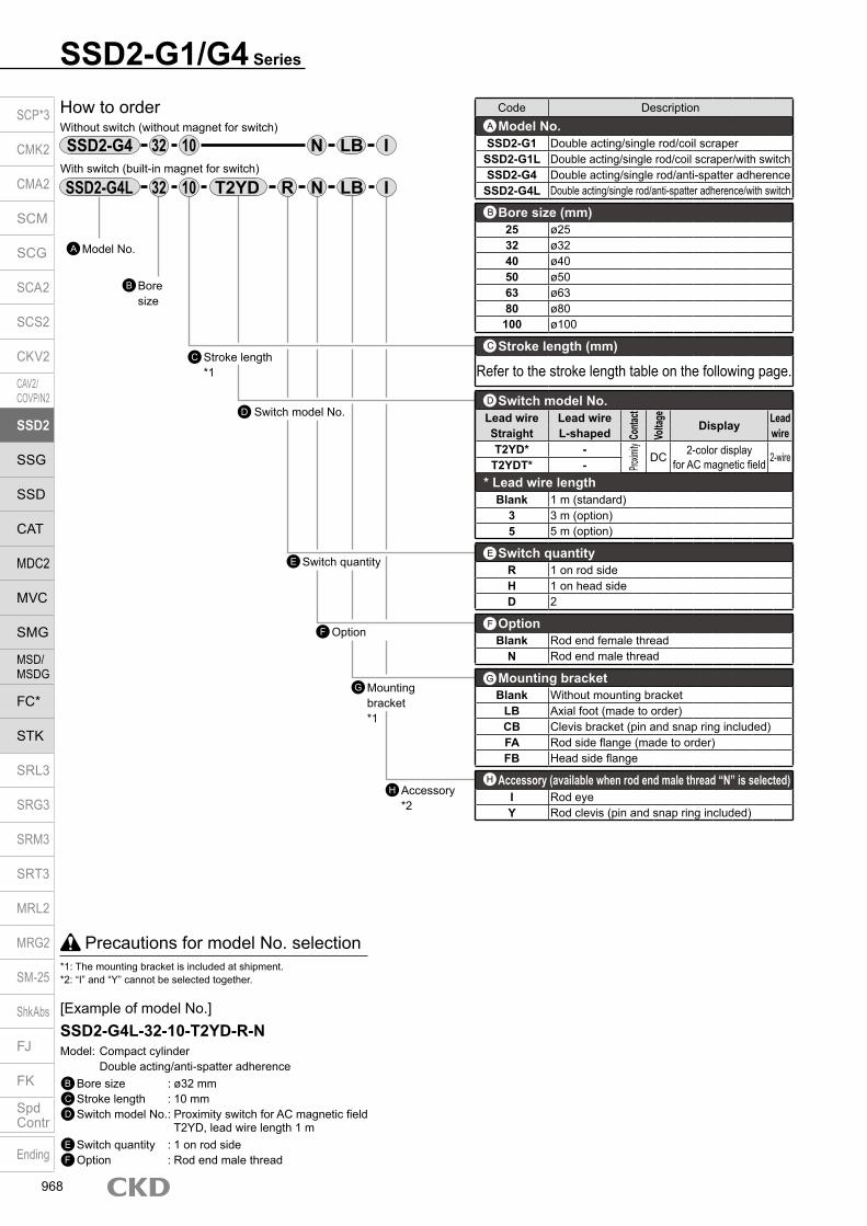
SSD2-G1/G4 Series
Precautions for model No. selection*1: The mounting bracket is included at shipment.*2: “I” and “Y” cannot be selected together.
[Example of model No.]SSD2-G4L-32-10-T2YD-R-NModel: Compact cylinder Double acting/anti-spatter adherenceB Bore size : ø32 mmC Stroke length : 10 mmD Switch model No. : Proximity switch for AC magnetic field T2YD, lead wire length 1 mE Switch quantity : 1 on rod sideF Option : Rod end male thread
Model No.A
Accessory *2
H
How to orderWithout switch (without magnet for switch)
With switch (built-in magnet for switch)
32 IN10
Mounting bracket *1
G
D
Bore size
B
Stroke length*1
C
Switch model No.
Switch quantityE
OptionF
32 R IN10
Code DescriptionModel No.
SSD2-G1 Double acting/single rod/coil scraperSSD2-G1L Double acting/single rod/coil scraper/with switchSSD2-G4 Double acting/single rod/anti-spatter adherence
SSD2-G4L Double acting/single rod/anti-spatter adherence/with switch
Bore size (mm)25 ø2532 ø3240 ø4050 ø5063 ø6380 ø80100 ø100
Stroke length (mm)
Refer to the stroke length table on the following page.
* Lead wire lengthBlank 1 m (standard)
3 3 m (option)5 5 m (option)
Switch quantityR 1 on rod sideH 1 on head sideD 2
OptionBlank Rod end female thread
N Rod end male thread
Mounting bracketBlank Without mounting bracket
LB Axial foot (made to order)CB Clevis bracket (pin and snap ring included)FA Rod side flange (made to order)FB Head side flange
Accessory (available when rod end male thread “N” is selected)I Rod eyeY Rod clevis (pin and snap ring included)
A
B
C
E
F
H
G
Switch model No.Lead wire Lead wire
Conta
ct
Volta
ge
Display Lead wireStraight L-shaped
T2YD* -
Proxim
ity
DC 2-color display for AC magnetic field 2-wireT2YDT* -
D
SSD2-G4 LB
SSD2-G4L T2YD LB
SCP*3
CMK2
CMA2
SCM
SCG
SCA2
SCS2
CKV2
CAV2/COVP/N2
SSD2
SSG
SSD
CAT
MDC2
MVC
SMG
MSD/MSDG
FC*
STK
SRL3
SRG3
SRM3
SRT3
MRL2
MRG2
SM‑25
ShkAbs
FJ
FK
SpdContr
Ending
968

SSD2-G1/G4 SeriesHow to order
Stroke length (mm)Applicable bore size
25 32 40 50 63 80 100
Sta
ndar
d st
roke
leng
th
5 10 15 20 25 30 35 40 45 50 75 100
Min. stroke length (mm) *1 1Max. stroke length (mm) 50 100Custom stroke length *2 In 1 mm increments
*1 : Less than 10 mm stroke length is not available. Refer to page 966 for the min. stroke length with switch.*2 : The total length when using a custom stroke length is the same as that when using the next longer standard
stroke length.
Bore size (mm)ø25 ø32 ø40 ø50 ø63 ø80
Mounting bracketFlange (FB) SSD2-FA-25 SSD2-G1-FA-32 SSD2-FA-40 SSD2-FA-50 SSD2-FA-63 SSD2-FA-80Clevis bracket (CB) SSD2-CB-25 SSD2-CB-32 SSD2-CB-40 SSD2-CB-50 SSD2-CB-63 SSD2-CB-80
How to order switch
Switch model No. (Item D on page 968)
*1: The foot mounting bracket is provided as 2 pcs./set.
[Stroke length table]
How to order mounting bracket
Bore size (mm)ø100
Mounting bracketFlange (FB) SSD2-FA-100Clevis bracket (CB) SSD2-CB-100
SW T2YD*
SCP*3
CMK2
CMA2
SCM
SCG
SCA2
SCS2
CKV2
CAV2/COVP/N2
SSD2
SSG
SSD
CAT
MDC2
MVC
SMG
MSD/MSDG
FC*
STK
SRL3
SRG3
SRM3
SRT3
MRL2
MRG2
SM‑25
ShkAbs
FJ
FK
SpdContr
Ending
969

SSD2-G1/G4 Series
Internal structure and parts list
No. Part name Material Remarks No. Part name Material Remarks
1 Piston rod ø25: Stainless steelø32 to ø100: Steel
Industrial chrome plating
8 Body Aluminum alloy Hard alumite
9 Piston packing Nitrile rubber
2 Coil scraper Phosphor bronze 10 Piston Aluminum alloy Chromate
3 C type snap ring Steel Zinc phosphate11 Cover ø25: Stainless steel
ø32 to ø100: Aluminum alloy ø32 to ø100: Alumite4 Lube keeping structure Special rubber G4 only
5 Rod metal gasket Nitrile rubber 12 Bush Oiles drymet
6 Rod metal ø25 to ø50: Special aluminumø63 to ø100: Aluminum alloy
ø25 to ø50: Alumiteø63 to ø100: Chromate
13 Spacer Aluminum alloy Chromate
14 Magnet Plastic
7 Rod packing Nitrile rubber
Part nameKit No. Repair parts No.
Bore size (mm)ø25 SSD2-G1-25K
2 5 7 9
ø32 SSD2-G1-32Kø40 SSD2-G1-40Kø50 SSD2-G1-50Kø63 SSD2-G1-63Kø80 SSD2-G1-80K
ø100 SSD2-G1-100K
Repair parts list
SSD2-G1L, G4L-25 to 50 (double acting/anti-spatter adherence/with switch)
SSD2-G1L, G4L-63 to 100 (double acting/anti-spatter adherence/with switch)
SSD2-G1, G4-25 to 50 (double acting/anti-spatter adherence) SSD2-G1, G4-63 to 100 (double acting/anti-spatter adherence)
1 2 4 3 6 7 5 8 13 14 9 10 11 1 2 4 7 3 6 5 12 8 13 14 9 10 11
1 2 4 3 6 5 7 8 9 10 11 13 1 2 4 7 3 5 6 12 8 9 10 11 13
Over 50 st Over 50 st
SCP*3
CMK2
CMA2
SCM
SCG
SCA2
SCS2
CKV2
CAV2/COVP/N2
SSD2
SSG
SSD
CAT
MDC2
MVC
SMG
MSD/MSDG
FC*
STK
SRL3
SRG3
SRM3
SRT3
MRL2
MRG2
SM‑25
ShkAbs
FJ
FK
SpdContr
Ending
970

Dimensions SSD2-G1L/G4L-25 to 100 (with switch/T0H/V, T5H/V, T2H/V, T3H/V)
Code Common dimensions with switch Proximity T2YDBore size (mm)
J K KA KK M MM N OUA
UBWF
HD RD *2
G1 G4 G1 G4ø25 9 spot face depth 5.5 51 M6 depth 11 M6 depth 12 10 12 28 - - - - 5 5 3 8.5
ø32 9 spot face depth 5.5 60 M6 depth 11 M8 depth 13 14 16 34 4.5 5 10 23 h9 12 17 3.5 8.5
ø40 9 spot face depth 5.5 69 M6 depth 11 M8 depth 13 14 16 40 5 5 10 28 h9 12 17 5.5 10.5
ø50 11 spot face depth 6.5 86 M8 depth 13 M10 depth 15 17 20 50 7 5 10 35 h9 13 18 6 11
ø63 14 spot face depth 9 103 M10 depth 25 M10 depth 15 17 20 60 7 5 10 35 h9 13 18 11 11.5
ø80 17.5 spot face depth 11 132 M12 depth 28 M16 depth 21 22 25 77 6 5 10 43 h9 15 20 16 14
ø100 17.5 spot face depth 11 156 M12 depth 28 M20 depth 27 27 30 94 6.5 5 10 59 h9 17 22 21.5 18
Codea’ c’ H kk’ M MM T
wfBore size (mm) G1 G4
ø25 17.5 15 17 M10×1.25 10 12 6 5 5
ø32 23.5 20.5 22 M14×1.5 14 16 8 10 15
ø40 23.5 20.5 22 M14×1.5 14 16 8 10 15
ø50 28.5 26 27 M18×1.5 17 20 11 10 15
ø63 28.5 26 27 M18×1.5 17 20 11 10 15
ø80 35.5 32.5 32 M22×1.5 22 25 13 13 18
ø100 35.5 32.5 41 M26×1.5 27 30 16 13 18
Rod end male thread
*1 : To calculate A+ stroke length or B+ stroke length when using custom stroke length, apply the next longer standard stroke length (instead of the custom stroke length) to the stroke length value. (Example) If the custom stroke length is 7 mm, apply the standard stroke length of 10 mm.
*2 : HD and RD dimensions for 5 mm stroke length differ from these dimensions according to the setting.*3 : For dimensions of individual accessories, refer to pages 1046 to 1049.*4 : Dimensions in ( ) of codes A and B are for stroke lengths of more than 50 mm.*5 : The ø32 bore size with a 5 mm stroke and without a switch has a port size of M5.*6 : Dimensions in ( ) of codes C and D are when the value is for a 5 mm stroke without switch.
Code Without switch Common dimensions with switchBore size (mm)
A *1
B *6 A *1
B *1 C *6 D *6 EE F FA FB G H IG1 G4 G1 G4
ø25 37.5 37.5 32.5 47.5 47.5 42.5 11 6 M5 40 31.5 17 - - 5.5
ø32 35(45) 40(50) 23(33) 45 50 33 8(10) 8(5.5) Rc1/8 *5 45 33.5 24 49.5 12.5 5.5
ø40 41.5(51.5) 46.5(56.5) 29.5(39.5) 51.5 56.5 39.5 12(11.5) 8.5(8) Rc1/8 52 37 31 57 15 5.5
ø50 43.5(53.5) 48.5(58.5) 30.5(40.5) 53.5 58.5 40.5 10.5 10.5 Rc1/4 64 43 32 71 18 6.9
ø63 49(59) 54(64) 36(46) 59 64 46 13 11 Rc1/4 77 49.5 32 84 23 8.7
ø80 58.5(68.5) 63.5(73.5) 43.5(53.5) 68.5 73.5 53.5 16 13 Rc3/8 98 60 32 104 31 10.5
ø100 70(80) 75(85) 53(63) 80 85 63 23 15 Rc3/8 117 69.5 32 123.5 38 10.5
Rod end male thread
SSD2-G1/G4-25 to 100 (without switch)
SSD2-G1/G4 SeriesDimensions
a’c’T
wf
øMM
kk’ Width across flats M
Width across flats H
G N
M
N
F FBFA
F
H8-J
Mounting hole
øMM
WF
KK
RD
C D
HD
2-EE
8-KAøI
A + stroke length
B + stroke length
KK
C D2-EE
8-KAøI
A + stroke length
B + stroke length
G
M
N
0F
F
H8-J
Mounting hole
øUB
UA
N
øMM
øUB
WFUA
O
øK
øK
SCP*3
CMK2
CMA2
SCM
SCG
SCA2
SCS2
CKV2
CAV2/COVP/N2
SSD2
SSG
SSD
CAT
MDC2
MVC
SMG
MSD/MSDG
FC*
STK
SRL3
SRG3
SRM3
SRT3
MRL2
MRG2
SM‑25
ShkAbs
FJ
FK
SpdContr
Ending
971

SSD2-G1/G4 Series
Dimensions with mounting bracket Clevis bracket (CB) SSD2-G1(L)/G4(L)-25 to 100 -CB
· ø25 · ø32 to ø100
Code Common dimensions Female thread
Bore size (mm) AC CA CB CC CD D E G H MR N UB
WF Without switch With switchA
BCJ A
BCJ
G1 G4 G1 G4 G1 G4 G1 G4 G1 G4ø25 - 24 10.2 14 10 5 40 M6×16 C2 - 28 20 5 5 67.5 67.5 32.5 57.5 57.5 77.5 77.5 42.5 67.5 67.5ø32 4.5 - 18.2 14 10 5 45 M6×16 C4 10 34 36 12 17 65 70 23 55 60 75 80 33 65 70ø40 5 - 18.2 14 10 6 52 M6×16 C5 10 40 36 12 17 73.5 78.5 29.5 63.5 68.5 83.5 88.5 39.5 73.5 78.5ø50 6 - 22.2 20 14 7 64 M8×20 - 14 50 44 13 18 85.5 90.5 30.5 71.5 76.5 95.5 100.5 40.5 81.5 86.5ø63 7 - 22.2 20 14 8 77 M10×25 - 14 60 44 13 18 93 98 36 79 84 103 108 46 89 94ø80 9 - 28.2 27 18 10 98 M12×40 - 18 77 56 15 20 114.5 119.5 43.5 96.5 101.5 124.5 129.5 53.5 106.5 111.5
ø100 12 - 32.2 31 22 13 117 M12×40 - 22 94 64 17 22 137 142 53 115 120 147 152 63 125 130Code Male thread
Bore size (mm) a’
wf Without switch With switchA
BCJ A
BCJ
G1 G4 G1 G4 G1 G4 G1 G4 G1 G4ø25 17.5 5 5 85 85 32.5 57.5 57.5 95 95 42.5 67.5 67.5ø32 23.5 10 15 86.5 91.5 23 53 58 96.5 101.5 33 63 68ø40 23.5 15 20 95 100 29.5 61.5 66.5 105 110 39.5 71.5 76.5ø50 28.5 15 20 111 116 30.5 68.5 73.5 121 126 40.5 78.5 83.5ø63 28.5 15 20 118.5 123.5 36 76 81 128.5 133.5 46 86 91ø80 35.5 18 23 148 153 43.5 94.5 99.5 158 163 53.5 104.5 109.5
ø100 35.5 18 23 168.5 173.5 53 111 116 178.5 183.5 63 121 126
NN
WF
A + stroke lengthB + stroke lengtha’ wf
A + stroke lengthRod end male thread
B + stroke lengtha’ wf
A + stroke lengthB + stroke lengthWF
Rod end male thread
A + stroke lengthB + stroke length
H
CJ + stroke lengthMounting bolt 4-C
N
E
E
CBCC
UBD
øCA
CD H10
CJ + stroke lengthCJ + stroke length
CJ + stroke length
CBCC
UBD
NE
ECD H10
Mounting bolt 4-GAC
R MR
SCP*3
CMK2
CMA2
SCM
SCG
SCA2
SCS2
CKV2
CAV2/COVP/N2
SSD2
SSG
SSD
CAT
MDC2
MVC
SMG
MSD/MSDG
FC*
STK
SRL3
SRG3
SRM3
SRT3
MRL2
MRG2
SM‑25
ShkAbs
FJ
FK
SpdContr
Ending
972

SSD2-G1/G4 SeriesDimensions with mounting bracket
Dimensions with mounting bracket Head side flange (FB) SSD2-G1(L)/G4(L)-25 to 100 -FB
· ø25 · ø32 to ø100
Code Common dimensions Female thread
Bore size (mm) FC FD FH FL FM FT N G WF Without switch With switch
A B A BG1 G4 G1 G4 G1 G4ø25 - 6.6 42 52 64 8 28 M6×16 5 5 45.5 45.5 32.5 55.5 55.5 42.5ø32 34 5.5 48 56 65 8 34 M6×16 12 17 43 48 23 53 58 33ø40 40 5.5 54 62 72 8 40 M6×16 12 17 49.5 54.5 29.5 59.5 64.5 39.5ø50 50 6.6 67 76 89 9 50 M8×20 13 18 52.5 57.5 30.5 62.5 67.5 40.5ø63 60 9 80 92 108 9 60 M10×25 13 18 58 63 36 68 73 46ø80 77 11 99 116 134 11 77 M12×40 15 20 69.5 74.5 43.5 79.5 84.5 53.5
ø100 94 11 117 136 154 11 94 M12×40 17 22 81 86 53 91 96 63Code Male thread
Bore size (mm) a’ wf Without switch With switch
A B A BG1 G4 G1 G4 G1 G4ø25 17.5 5 5 63 63 32.5 73 73 42.5ø32 23.5 10 15 64.5 69.5 23 74.5 79.5 33ø40 23.5 15 20 71 76 29.5 81 86 39.5ø50 28.5 15 20 78 83 30.5 88 93 40.5ø63 28.5 15 20 83.5 88.5 36 93.5 98.5 46ø80 35.5 18 23 103 108 43.5 113 118 53.5
ø100 35.5 18 23 112.5 117.5 53 122.5 127.5 63
N
FM
FHWF
Mounting bolt 4-GHexagon socket button head bolt
FH FC
A + stroke lengthB + stroke lengtha’ wf FT
A + stroke length
Rod end male thread
B + stroke lengtha’ wf
A + stroke lengthB + stroke lengthFL WF
FT
Rod end male thread
A + stroke length
B + stroke length FT N
2-FD
4-FDFLN
Mounting bolt 4-G
FM
FT
ø32 to ø63: Hexagon socket button head boltø80/ø100: Special bolt
SCP*3
CMK2
CMA2
SCM
SCG
SCA2
SCS2
CKV2
CAV2/COVP/N2
SSD2
SSG
SSD
CAT
MDC2
MVC
SMG
MSD/MSDG
FC*
STK
SRL3
SRG3
SRM3
SRT3
MRL2
MRG2
SM‑25
ShkAbs
FJ
FK
SpdContr
Ending
973

Compact cylinder double acting/single rod/high load/coil scraper
SSD2-KG1 Series
JIS symbol
SpecificationsItem SSD2-KG1/KG4
SSD2-KG1L/KG4L (with switch)Bore size mm ø25 ø32 ø40 ø50 ø63 ø80 ø100Actuation Double actingWorking fluid Compressed airMax. working pressure MPa 1.0 (≈150 psi, 10 bar)Min. working pressure MPa 0.15 (≈22 psi, 1.5 bar) 0.1 (≈15 psi, 1 bar)Proof pressure MPa 1.6 (≈230 psi, 16 bar)Ambient temperature °C -10 (14°F) to 60 (140°F) (no freezing)Port size M5 Rc1/8 Rc1/4 Rc3/8Stroke tolerance mm +2.0
0
Working piston speed mm/s 50 to 500 50 to 300Cushion Rubber cushionLubrication Not required (use turbine oil ISO VG32 if necessary for lubrication)Allowable absorbed energy J 0.16 0.40 0.63 0.98 1.56 2.51 3.92
Bore size: ø25/ø32/ø40/ø50/ø63/ø80/ø100
Compact cylinder double acting/single rod/high load/anti-spatter adherence
SSD2-KG4 Series
Stroke length
*1: The custom stroke is available in 1 mm increments.*2: Dimensions of custom stroke length (example: 64 mm stroke length) are the same as the next stroke length up
(example: 75 mm stroke length).
Bore size (mm) Standard stroke length (mm) Max. stroke length (mm) Min. stroke length (mm)
ø255/10/15/20/25/ 30/35/40/45/50
50
1(10)The value in ( ) is for types with one or two switches.
ø32 5/10/15/20/25/30/35/40/45/50/75/100
100
ø40ø50
10/15/20/2530/35/40/45/50
75/100
ø63ø80ø100
Custom stroke length SSD2-KG1, KG4 Series
ItemStandard products
Standard stroke length body with spacerModel No. Refer to How to order.
DescriptionA spacer is added to the standard stroke length body to adjust the stroke length in 1 mm increments.
Stroke rangeBore size Stroke range
25 1 to 4932 to 100 1 to 99
Example of model No.Model No.: SSD2-KG1-32-38A +2 mm spacer is added to the SSD2-KG1-32-40 standard cylinder to create 38 mm stroke length. B + stroke length is 83mm.
A + stroke length
B + stroke length
SCP*3
CMK2
CMA2
SCM
SCG
SCA2
SCS2
CKV2
CAV2/COVP/N2
SSD2
SSG
SSD
CAT
MDC2
MVC
SMG
MSD/MSDG
FC*
STK
SRL3
SRG3
SRM3
SRT3
MRL2
MRG2
SM‑25
ShkAbs
FJ
FK
SpdContr
Ending
974

SSD2-KG1/KG4 SeriesSpecifications
Switch specifications
ItemProximity 2-wire
T2YD/T2YDTApplications Dedicated for programmable controllerIndicator lamp Red/green LED (Lit when ON)Load voltage 24 VDC ±10%Load current 5 to 20 mAInternal voltage drop 6 V or lessLeakage current 1.0 mA or lessOutput delay time *1(Delay ON, delay OFF)
30 to 60 ms
Lead wire length1 m (oil resistant vinyl cabtyre cableø 6, 0.5 mm2 x 2-conductor) *2, *3
Insulation resistance 100 MΩ and over at 500 VDC meggerWithstand voltage No failure after 1 minute of 1,000 VAC application.Max. shock resistance 980 m/s2
Ambient temperature -10 to +60°CDegree of protection JIS C0920 (water-tight), IEC standards IP67, oil resistanceWeight g 1 m:61 3 m:166 5 m:272
*1: Indicates the time from magnetic sensor detection of the piston magnet until switch output.*2: 3 m and 5 m lead wires are available as options.*3: Flame-resistant lead wires are available as options.*4: This switch cannot be used in DC environments.
Theoretical thrust tableBore size
(mm)Operating direction
Working pressure MPa0.1 0.15 0.2 0.3 0.4 0.5 0.6 0.7 0.8 0.9 1.0
ø25Push - 73.6 98.2 1.47×10² 1.96×10² 2.45×10² 2.95×10² 3.44×10² 3.93×10² 4.42×10² 4.91×10²
Pull - 56.7 75.6 1.13×10² 1.51×10² 1.89×10² 2.27×10² 2.64×10² 3.02×10² 3.40×10² 3.78×10²
ø32Push - 1.21×10² 1.61×10² 2.41×10² 3.22×10² 4.02×10² 4.83×10² 5.63×10² 6.43×10² 7.24×10² 8.04×10²
Pull - 90.5 1.21×10² 1.81×10² 2.41×10² 3.02×10² 3.62×10² 4.22×10² 4.83×10² 5.43×10² 6.03×10²
ø40Push - 1.88×10² 2.51×10² 3.77×10² 5.03×10² 6.28×10² 7.54×10² 8.80×10² 1.01×10³ 1.13×10³ 1.26×10³
Pull - 1.58×10² 2.11×10² 3.17×10² 4.22×10² 5.28×10² 6.33×10² 7.39×10² 8.44×10² 9.50×10² 1.06×10³
ø50Push - 2.95×10² 3.93×10² 5.89×10² 7.85×10² 9.82×10² 1.18×10³ 1.37×10³ 1.57×10³ 1.77×10³ 1.96×10³
Pull - 2.47×10² 3.30×10² 4.95×10² 6.60×10² 8.25×10² 9.90×10² 1.15×10³ 1.32×10³ 1.48×10³ 1.65×10³
ø63Push 3.12×10² 4.68×10² 6.23×10² 9.35×10² 1.25×10³ 1.56×10³ 1.87×10³ 2.18×10³ 2.49×10³ 2.81×10³ 3.12×10³
Pull 2.80×10² 4.20×10² 5.61×10² 8.41×10² 1.12×10³ 1.40×10³ 1.68×10³ 1.96×10³ 2.24×10³ 2.52×10³ 2.80×10³
ø80Push 5.03×10² 7.54×10² 1.01×10³ 1.51×10³ 2.01×10³ 2.51×10³ 3.02×10³ 3.52×10³ 4.02×10³ 4.52×10³ 5.03×10³
Pull 4.54×10² 6.80×10² 9.07×10² 1.36×10³ 1.81×10³ 2.27×10³ 2.72×10³ 3.17×10³ 3.63×10³ 4.08×10³ 4.54×10³
ø100Push 7.85×10² 1.18×10³ 1.57×10³ 2.36×10³ 3.14×10³ 3.93×10³ 4.71×10³ 5.50×10³ 6.28×10³ 7.07×10³ 7.85×10³
Pull 7.15×10² 1.07×10³ 1.43×10³ 2.14×10³ 2.86×10³ 3.57×10³ 4.29×10³ 5.00×10³ 5.72×10³ 6.43×10³ 7.15×10³
(Unit: N)
Stroke length (mm) 5 10 15 20 25 30 35 40 45 50 75 100Bore size (mm) No switch Switch No switch Switch No switch Switch No switch Switch No switch Switch No switch Switch No switch Switch No switch Switch No switch Switch No switch Switch No switch Switch No switch Switch
ø25 146 237 162 253 178 269 194 285 209 300 226 317 242 333 258 349 274 365 290 381 - - - -ø32 228 342 249 363 270 384 292 406 314 428 336 450 358 472 379 493 401 515 422 536 530 644 637 751 ø40 318 461 345 488 372 515 398 541 424 567 451 594 478 621 504 647 531 674 557 700 690 833 822 965 ø50 - - 549 743 591 785 634 828 677 871 718 912 760 954 802 996 844 1038 886 1080 1096 1290 1306 1500 ø63 - - 782 1061 837 1116 892 1171 948 1227 1003 1282 1058 1337 1113 1392 1168 1447 1223 1502 1498 1777 1773 2052 ø80 - - 1382 1795 1469 1882 1555 1968 1642 2055 1729 2142 1816 2229 1902 2315 1989 2402 2075 2488 2508 2921 2940 3353
ø100 - - 2029 2596 2143 2710 2257 2824 2371 2938 2484 3051 2598 3165 2712 3279 2826 3393 2940 3507 3510 4077 4080 4647
Cylinder weight table (the weight of the switches is when there are 2 cylinder switches.) (Unit: g)
SCP*3
CMK2
CMA2
SCM
SCG
SCA2
SCS2
CKV2
CAV2/COVP/N2
SSD2
SSG
SSD
CAT
MDC2
MVC
SMG
MSD/MSDG
FC*
STK
SRL3
SRG3
SRM3
SRT3
MRL2
MRG2
SM‑25
ShkAbs
FJ
FK
SpdContr
Ending
975

SSD2-KG1/KG4 Series
Precautions for model No. selection*1: The mounting bracket is included at shipment.*2: “I” and “Y” cannot be selected together.
[Example of model No.]SSD2-KG4L-32-10-T2YD-R-NModel: Compact cylinder Double acting, high load, anti-spatter adherenceB Bore size : ø32 mmC Stroke length : 10 mmD Switch model No. : Proximity switch for AC magnetic field T2YD, lead wire length 1 mE Switch quantity : 1 on rod sideF Option : Rod end male thread
Model No.A
Accessory *2
H
How to orderWithout switch (without magnet for switch)
With switch (built-in magnet for switch)
32 10
Mounting bracket *1
G
OptionF
Bore size
B
Switch quantityE
D Switch model No.
Stroke lengthC
32
IN
R IN10
Code DescriptionModel No.
SSD2-KG1 Double acting/single rod/high load/coil scraperSSD2-KG1L Double acting/single rod/high load/coil scraper/with switchSSD2-KG4 Double acting/single rod/high load/anti-spatter adherence
SSD2-KG4L Double acting/single rod/high load/anti-spatter adherence/with switch
Bore size (mm)25 ø2532 ø3240 ø4050 ø5063 ø6380 ø80100 ø100
Stroke length (mm)
Refer to the stroke length table on the following page.
* Lead wire lengthBlank 1 m (standard)
3 3 m (option)5 5 m (option)
Switch quantityR 1 on rod sideH 1 on head sideD 2
OptionBlank Rod end female thread
N Rod end male thread
Mounting bracketBlank Without mounting bracket
LB Axial foot (made-to-order product)CB Clevis bracket (pin and snap ring included)FA Rod side flange (made-to-order product)FB Head side flange
Accessory (available when rod end male thread “N” is selected)I Rod eyeY Rod clevis (pin and snap ring included)
A
B
C
E
F
H
G
Switch model No.Lead wire Lead wire
Conta
ct
Volta
ge
Display Lead wireStraight L-shaped
T2YD* -
Proxim
ity
DC 2-color display for AC magnetic field 2-wireT2YDT* -
D
SSD2-KG4
SSD2-KG4L
LB
LBT2YD
SCP*3
CMK2
CMA2
SCM
SCG
SCA2
SCS2
CKV2
CAV2/COVP/N2
SSD2
SSG
SSD
CAT
MDC2
MVC
SMG
MSD/MSDG
FC*
STK
SRL3
SRG3
SRM3
SRT3
MRL2
MRG2
SM‑25
ShkAbs
FJ
FK
SpdContr
Ending
976

SSD2-KG1/KG4 SeriesHow to order
How to order switch
Switch model No. (Item D on page 976)
*1: Less than 10 mm stroke length is not available.*2: The total length is the same as that of the next longer standard stroke length.
Bore size (mm)ø25 ø32 ø40 ø50 ø63 ø80 ø100
Mounting bracketFlange (FB) SSD2-FA-25 SSD2-G1-FA-32 SSD2-FA-40 SSD2-FA-50 SSD2-FA-63 SSD2-FA-80 SSD2-FA-100Clevis bracket (CB) SSD2-CB-25 SSD2-CB-32 SSD2-CB-40 SSD2-CB-50 SSD2-CB-63 SSD2-CB-80 SSD2-CB-100
How to order mounting bracket
*1: The foot mounting bracket is provided as 2 pcs./set.
Stroke length (mm)Applicable bore size
25 32 40 50 63 80 100
Sta
ndar
d st
roke
leng
th
5 10 15 20 25 30 35 40 45 50 75 100
Min. stroke length (mm) *1 1Max. stroke length (mm) 50 100Custom stroke length *2 In 1 mm increments
[Stroke length table]
SW T2YDSCP*3
CMK2
CMA2
SCM
SCG
SCA2
SCS2
CKV2
CAV2/COVP/N2
SSD2
SSG
SSD
CAT
MDC2
MVC
SMG
MSD/MSDG
FC*
STK
SRL3
SRG3
SRM3
SRT3
MRL2
MRG2
SM‑25
ShkAbs
FJ
FK
SpdContr
Ending
977

Internal structure and parts list SSD2-KG1L/KG4L-25 (double acting/single rod high load/anti-spatter adherence/with switch)
SSD2-KG1/KG4-25 (double acting/single rod/high load/anti-spatter adherence)
No. Part name Material Remarks No. Part name Material Remarks
1 Piston rod ø25: Stainless steelø32 to ø50: Steel
Industrial chrome plating
10 Cushion rubber R Urethane rubber
11 Cushion rubber H Urethane rubber
2 C type snap ring for hole Steel Zinc phosphate 12 Spacer Aluminum alloy ø25, ø32: Chromate
3 Coil scraper Phosphor bronze 13 Magnet Plastic
4 Rod metal gasket Nitrile rubber 14 Piston Aluminum alloy Chromate
5 Lube keeping structure Special rubber G4 only 15 Piston packing Nitrile rubber
6 Rod metal Special aluminum Alumite 16 Wear ring Polyacetal resin
7 Rod packing Nitrile rubber17 Cover ø25: Stainless steel
ø32 to 50: Aluminum alloy ø32 to ø50: Alumite8 Bush Oiles drymet
9 Body Aluminum alloy Hard alumite
SSD2-KG1/KG4 Series
SSD2-KG1L/KG4L-32 to 50 (double acting/single rod high load/anti-spatter adherence/with switch)
SSD2-KG1/KG4-32 to 50 (double acting/single rod/high load/anti-spatter adherence)
Part nameKit No. Repair parts No.
Bore size (mm)ø25 SSD2-KG1-25K
3 4 7
10 11 15 16
ø32 SSD2-KG1-32Kø40 SSD2-KG1-40Kø50 SSD2-KG1-50K
Repair parts list
1 3 5 2 6 4 7 8 10 9 12 13 15 16 14 11 17 1 3 5 2 6 4 7 8 10 9 12 13 15 16 14 11 17
1 3 5 2 6 4 7 8 10 9 15 16 14 11 17 1 3 5 2 6 4 7 8 10 9 15 16 14 11 17
SCP*3
CMK2
CMA2
SCM
SCG
SCA2
SCS2
CKV2
CAV2/COVP/N2
SSD2
SSG
SSD
CAT
MDC2
MVC
SMG
MSD/MSDG
FC*
STK
SRL3
SRG3
SRM3
SRT3
MRL2
MRG2
SM‑25
ShkAbs
FJ
FK
SpdContr
Ending
978

SSD2-KG1L/KG4L-32 to 50 (double acting/single rod high load/anti-spatter adherence/with switch)
Internal structure and parts list SSD2-KG1L/KG4L-63 to 100 (double acting/single rod high load/anti-spatter adherence/with switch)
SSD2-KG1/KG4 SeriesInternal structure and parts list
SSD2-KG1/KG4-63 to 100 (double acting/single rod high load/anti-spatter adherence)
No. Part name Material Remarks No. Part name Material Remarks1 Piston rod Steel Industrial chrome plating 10 Cushion rubber R Urethane rubber
2 C type snap ring for hole Steel Zinc phosphate 11 Cushion rubber H Urethane rubber
3 Coil scraper Phosphor bronze 12 Spacer Aluminum alloy Chromate
4 Rod metal gasket Nitrile rubber 13 Magnet Plastic
5 Lube keeping structure Special rubber G4 only 14 Piston Aluminum alloy Chromate
6 Rod metal Aluminum alloy Chromate 15 Piston packing Nitrile rubber
7 Rod packing Nitrile rubber 16 Wear ring Polyacetal resin
8 Bush Oiles drymet 17 Cover Aluminum alloy Alumite
9 Body Aluminum alloy Hard alumite
Part nameKit No. Repair parts No.
Bore size (mm)ø63 SSD2-KG1-63K
3 4 7 10
11 15 16ø80 SSD2-KG1-80K
ø100 SSD2-KG1-100K
Repair parts list
1 3 5 2 7 4 6 8 10 9 12 13 15 16 14 11 17
1 3 5 2 7 4 6 8 10 9 15 16 14 11 17
SCP*3
CMK2
CMA2
SCM
SCG
SCA2
SCS2
CKV2
CAV2/COVP/N2
SSD2
SSG
SSD
CAT
MDC2
MVC
SMG
MSD/MSDG
FC*
STK
SRL3
SRG3
SRM3
SRT3
MRL2
MRG2
SM‑25
ShkAbs
FJ
FK
SpdContr
Ending
979

SSD2-KG1/KG4 Series
Dimensions SSD2-KG1L/KG4L-25 to 100 (with switch/T0H/V, T5H/V, T2H/V, T3H/V)
Code Dimensions with switch Proximity T2YDBore size (mm)
KK M MM N OUA
UBWF
HD RD *2
G1 G4 G1 G4ø25 M6 depth 12 10 12 28 - - - - 5 5 2 20
ø32 M8 depth 13 14 16 34 4.5 5 10 23 h9 12 17 4.5 20.5
ø40 M8 depth 13 14 16 40 5 5 10 28 h9 12 17 8 23.5
ø50 M10 depth 15 17 20 50 7 5 10 35 h9 13 18 9 23.5
ø63 M10 depth 15 17 20 60 7 5 10 35 h9 13 18 13 24
ø80 M16 depth 21 22 25 77 6 5 10 43 h9 15 20 19 26.5
ø100 M20 depth 27 27 30 94 6.5 5 10 59 h9 17 22 24.5 30.5
Codea’ c’ H kk’ M MM T
wfBore size (mm) G1 G4
ø25 17.5 15 17 M10×1.25 10 12 6 5 5
ø32 23.5 20.5 22 M14×1.5 14 16 8 10 15
ø40 23.5 20.5 22 M14×1.5 14 16 8 10 15
ø50 28.5 26 27 M18×1.5 17 20 11 10 15
ø63 28.5 26 27 M18×1.5 17 20 11 10 15
ø80 35.5 32.5 32 M22×1.5 22 25 13 13 18
ø100 35.5 32.5 41 M26×1.5 27 30 16 13 18
Rod end male thread
*1 : To calculate A+ stroke length or B+ stroke length when using custom stroke length, apply the next longer standard stroke length (instead of the custom stroke length) to the stroke length value. (Example) If the custom stroke length is 7 mm, apply the standard stroke length of 10 mm.
*2 : HD and RD dimensions for 5 mm stroke length differ from these dimensions according to the setting.*3 : For dimensions of individual accessories, refer to pages 1046 to 1049.
Rod end male thread
Code Dimensions with switchBore size (mm)
A *1
B *1 C D EE F FA FB G H I J K KAG1 G4
ø25 52.5 52.5 47.5 11 6 M5 40 31.5 17 - - 5.5 9 spot face depth 5.5 51 M6 depth 11
ø32 55 60 43 8 8 Rc1/8 45 33.5 24 49.5 12.5 5.5 9 spot face depth 5.5 60 M6 depth 11
ø40 61.5 66.5 49.5 12 8.5 Rc1/8 52 37 31 57 15 5.5 9 spot face depth 5.5 69 M6 depth 11
ø50 63.5 68.5 50.5 10.5 10.5 Rc1/4 64 43 32 71 18 6.9 11 spot face depth 6.5 86 M8 depth 13
ø63 69 74 56 13 11 Rc1/4 77 49.5 32 84 23 8.7 14 spot face depth 9 103 M10 depth 25
ø80 78.5 83.5 63.5 16 13 Rc3/8 98 60 32 104 31 10.5 17.5 spot face depth 11 132 M12 depth 28
ø100 90 95 73 23 15 Rc3/8 117 69.5 32 123.5 38 10.5 17.5 spot face depth 11 156 M12 depth 28
G N
M
N
F FB
FA
F
H8-J
Mounting hole
øMM
WF
KK
RD
C D
HD
2-EE
8-KAøI
A + stroke length
B + stroke length
øUB
UA
O
a’c’T
wf
øMM
kk’ Width across flats M
Width across flats H
SCP*3
CMK2
CMA2
SCM
SCG
SCA2
SCS2
CKV2
CAV2/COVP/N2
SSD2
SSG
SSD
CAT
MDC2
MVC
SMG
MSD/MSDG
FC*
STK
SRL3
SRG3
SRM3
SRT3
MRL2
MRG2
SM‑25
ShkAbs
FJ
FK
SpdContr
Ending
980

Dimensions SSD2-KG1/KG4-25 to 100 (without switch)
Codea’ c’ H kk’ M MM T
wfBore size (mm) G1 G4
ø25 17.5 15 17 M10×1.25 10 12 6 5 5
ø32 23.5 20.5 22 M14×1.5 14 16 8 10 15
ø40 23.5 20.5 22 M14×1.5 14 16 8 10 15
ø50 28.5 26 27 M18×1.5 17 20 11 10 15
ø63 28.5 26 27 M18×1.5 17 20 11 10 15
ø80 35.5 32.5 32 M22×1.5 22 25 13 13 18
ø100 35.5 32.5 41 M26×1.5 27 30 16 13 18
Rod end male thread
*1 : To calculate A+ stroke length or B+ stroke length when using custom stroke length, apply the next longer standard stroke length (instead of the custom stroke length) to the stroke length value. (Example) If the custom stroke length is 7 mm, apply the standard stroke length of 10 mm.
*2 : HD and RD dimensions for 5 mm stroke length differ from these dimensions according to the setting.*3 : For dimensions of individual accessories, refer to pages 1046 to 1049.*4 : Dimensions in ( ) of codes A and B are for stroke lengths of more than 50 mm.*5 : The ø32 bore size with a 5 mm stroke and without a switch has a port size of M5.
Code Dimensions without switchBore size (mm)
A *1, *4
B *1, *4 C D EE *5 F G H I J K KAG1 G4
ø25 42.5 42.5 37.5 11 6 M5 40 - - 5.5 9 spot face depth 5.5 51 M6 depth 11
ø32 45(55) 50(60) 33(43) 10 5.5 Rc1/8 45 49.5 12.5 5.5 9 spot face depth 5.5 60 M6 depth 11
ø40 51.5(61.5) 56.5(66.5) 39.5(49.5) 11.5 8 Rc1/8 52 57 15 5.5 9 spot face depth 5.5 69 M6 depth 11
ø50 53.5(63.5) 58.5(68.5) 40.5(50.5) 10.5 10.5 Rc1/4 64 71 18 6.9 11 spot face depth 6.5 86 M8 depth 13
ø63 59(69) 64(74) 46(56) 13 11 Rc1/4 77 84 23 8.7 14 spot face depth 9 103 M10 depth 25
ø80 68.5(78.5) 73.5(83.5) 53.5(63.5) 16 13 Rc3/8 98 104 31 10.5 17.5 spot face depth 11 132 M12 depth 28
ø100 80(90) 85(95) 63(73) 23 15 Rc3/8 117 123.5 38 10.5 17.5 spot face depth 11 156 M12 depth 28
Rod end male thread
SSD2-KG1/KG4 SeriesDimensions
Code Dimensions without switchBore size (mm)
KK M MM N OUA
UBWF
G1 G4 G1 G4ø25 M6 depth 12 10 12 28 - - - - 5 5
ø32 M8 depth 13 14 16 34 4.5 5 10 23 h9 12 17
ø40 M8 depth 13 14 16 40 5 5 10 28 h9 12 17
ø50 M10 depth 15 17 20 50 7 5 10 35 h9 13 18
ø63 M10 depth 15 17 20 60 7 5 10 35 h9 13 18
ø80 M16 depth 21 22 25 77 6 5 10 43 h9 15 20
ø100 M20 depth 27 27 30 94 6.5 5 10 59 h9 17 22
KK
C D2-EE
8-KA
øI
A + stroke length
B + stroke length
G
M
N
OF
F
H8-J
Mounting hole
N
øMM
øUB
WF
UA
a’c’T
wf
øMM
kk’ Width across flats M
Width across flats H
SCP*3
CMK2
CMA2
SCM
SCG
SCA2
SCS2
CKV2
CAV2/COVP/N2
SSD2
SSG
SSD
CAT
MDC2
MVC
SMG
MSD/MSDG
FC*
STK
SRL3
SRG3
SRM3
SRT3
MRL2
MRG2
SM‑25
ShkAbs
FJ
FK
SpdContr
Ending
981

Dimensions with mounting bracketClevis bracket (CB) SSD2-KG1(L)/KG4(L)-25 to 100 -CB
· ø25 · ø32 to ø100
SSD2-KG1/KG4 Series
Code Common dimensions Female thread
Bore size (mm) AC CA CB CC CD D E G H MR N UB
WF Without switch With switchA
BCJ A
BCJ
G1 G4 G1 G4 G1 G4 G1 G4 G1 G4ø25 - 24 10.2 14 10 5 40 M6×16 C5 - 28 20 5 5 72.5 72.5 37.5 62.5 62.5 82.5 82.5 47.5 72.5 72.5ø32 4.5 - 18.2 14 10 5 45 M6×16 - 10 34 36 12 17 75 80 33 65 70 85 90 43 75 80ø40 5 - 18.2 14 10 6 52 M6×16 - 10 40 36 12 17 83.5 88.5 39.5 73.5 78.5 93.5 98.5 49.5 83.5 88.5ø50 6 - 22.2 20 14 7 64 M8×20 - 14 50 44 13 18 95.5 100.5 40.5 81.5 86.5 105.5 110.5 50.5 91.5 96.5ø63 7 - 22.2 20 14 8 77 M10×25 - 14 60 44 13 18 103 108 46 89 94 113 118 56 99 104ø80 9 - 28.2 27 18 10 98 M12×40 - 18 77 56 15 20 124.5 129.5 53.5 106.5 111.5 134.5 139.5 63.5 116.5 121.5
ø100 12 - 32.2 31 22 13 117 M12×40 - 22 94 64 17 22 147 152 63 125 130 157 162 73 135 140Code Male thread
Bore size (mm) a’
wf Without switch With switchA
BCJ A
BCJ
G1 G4 G1 G4 G1 G4 G1 G4 G1 G4ø25 17.5 5 5 90 90 37.5 62.5 62.5 100 100 47.5 72.5 72.5ø32 23.5 10 15 96.5 101.5 33 63 68 106.5 111.5 43 73 78ø40 23.5 15 20 105 110 39.5 71.5 76.5 115 120 49.5 81.5 86.5ø50 28.5 15 20 121 126 40.5 78.5 83.5 131 136 50.5 88.5 93.5ø63 28.5 15 20 128.5 133.5 46 86 91 138.5 143.5 56 96 101ø80 35.5 18 23 158 163 53.5 104.5 109.5 168 173 63.5 114.5 119.5
ø100 35.5 18 23 178.5 183.5 63 121 126 188.5 193.5 73 131 136
NN
WF
A + stroke lengthB + stroke lengtha’ wf
A + stroke lengthRod end male thread
B + stroke lengtha’ wf
A + stroke lengthB + stroke lengthWF
Rod end male thread
A + stroke lengthB + stroke length
H
CJ + stroke lengthMounting bolt 4-C
N
E
E
CC
UBD
øCA
CD H10
CJ + stroke lengthCJ + stroke length
CJ + stroke length
CC
UBD
NE
ECD H10
Mounting bolt 4-CAC
R MR
CB + 0.2 0
CB + 0.2 0
SCP*3
CMK2
CMA2
SCM
SCG
SCA2
SCS2
CKV2
CAV2/COVP/N2
SSD2
SSG
SSD
CAT
MDC2
MVC
SMG
MSD/MSDG
FC*
STK
SRL3
SRG3
SRM3
SRT3
MRL2
MRG2
SM‑25
ShkAbs
FJ
FK
SpdContr
Ending
982

Dimensions with mounting bracket Head side flange (FB) SSD2-KG1(L)/KG4(L)-20 to 100 -FB
· ø25 · ø32 to ø100
SSD2-KG1/KG4 SeriesDimensions with mounting bracket
Code Common dimensions Female thread
Bore size (mm) FC FD FH FL FM FT N G WF Without switch With switch
A B A BG1 G4 G1 G4 G1 G4ø25 - 6.6 42 52 64 8 28 M6×16 5 5 50.5 50.5 37.5 60.5 60.5 47.5ø32 34 5.5 48 56 65 8 34 M6×16 12 17 53 58 33 63 68 43ø40 40 5.5 54 62 72 8 40 M6×16 12 17 59.5 64.5 39.5 69.5 74.5 49.5ø50 50 6.6 67 76 89 9 50 M8×20 13 18 62.5 67.5 40.5 72.5 77.5 50.5ø63 60 9 80 92 108 9 60 M10×25 13 18 68 73 46 78 83 56ø80 77 11 99 116 134 11 77 M12×40 15 20 79.5 84.5 53.5 89.5 94.5 63.5
ø100 94 11 117 136 154 11 94 M12×40 17 22 91 96 63 101 106 73Code Male thread
Bore size (mm) a’ wf Without switch With switch
A B A BG1 G4 G1 G4 G1 G4ø25 17.5 5 5 68 68 37.5 78 78 47.5ø32 23.5 10 15 74.5 79.5 33 84.5 89.5 43ø40 23.5 15 20 81 86 39.5 91 96 49.5ø50 28.5 15 20 88 93 40.5 98 103 50.5ø63 28.5 15 20 93.5 98.5 46 103.5 108.5 56ø80 35.5 18 23 113 118 53.5 123 128 63.5
ø100 35.5 18 23 122.5 127.5 63 132.5 137.5 73
N
FM
FHWF
Mounting bolt 4-GHexagon socket button head bolt
FH FC
A + stroke lengthB + stroke lengtha’ wf FT
A + stroke length
Rod end male thread
B + stroke lengtha’ wf
A + stroke lengthB + stroke lengthFL WF
FT
Rod end male thread
A + stroke length
B + stroke length FT N
2-FD
4-FDFLN
Mounting bolt 4-G
FM
FT
ø32 to ø63: Hexagon socket button head boltø80/ø100: Special bolt
SCP*3
CMK2
CMA2
SCM
SCG
SCA2
SCS2
CKV2
CAV2/COVP/N2
SSD2
SSG
SSD
CAT
MDC2
MVC
SMG
MSD/MSDG
FC*
STK
SRL3
SRG3
SRM3
SRT3
MRL2
MRG2
SM‑25
ShkAbs
FJ
FK
SpdContr
Ending
983

JIS symbol
SpecificationsItem SSD2-DG1/DG4
SSD2-DG1L/DG4L (with switch)Bore size mm ø25 ø32 ø40 ø50 ø63 ø80 ø100Actuation Double actingWorking fluid Compressed airMax. working pressure MPa 1.0 (≈150 psi, 10 bar)Min. working pressure MPa 0.2 (≈29 psi, 2 bar) 0.15 (≈22 psi, 1.5 bar)Proof pressure MPa 1.6 (≈230 psi, 16 bar)Ambient temperature °C -10 (14°F) to 60 (140°F) (no freezing)Port size Rc1/8 Rc1/4 Rc3/8Stroke tolerance mm +1.0
0
Working piston speed mm/s 50 to 500 50 to 300Cushion NoneLubrication Not required (use turbine oil ISO VG32 if necessary for lubrication)Allowable absorbed energy J 0.021 0.025 0.092 0.1 0.12 0.27 0.56
*1: The custom stroke is available in 1 mm increments.
Compact cylinder double acting/ double rod/coil scraper
SSD2-DG1 Series Bore size: ø25/ø32/ø40/ø50/ø63/ø80/ø100
Compact cylinder double acting/ double rod/anti-spatter adherence
SSD2-DG4 Series
Stroke lengthBore size (mm) Standard stroke length (mm) Max. stroke length (mm) Min. stroke length (mm)
ø255/10/15/20/25/ 30/35/40/45/50
50
1(10)The value in ( ) is for types with one or two switches.
ø32 5/10/15/20/25/30/35/40/45/50/75/100
100
ø40ø50
10/15/20/2530/35/40/45/50
75/100
ø63ø80ø100
Custom stroke length SSD2-DG1, DG4 Series
ItemStandard products
Standard stroke length body with spacerModel No. Refer to How to order.
DescriptionA spacer is added to the standard stroke length body to adjust the stroke length in 1 mm increments.
Stroke rangeBore size Stroke range
25 1 to 4932 to 100 1 to 99
Example of model No.Model No.: SSD2-DG1-32-38A +2 mm spacer is added to the SSD2-DG1-32-40 standard cylinder to create 38 mm stroke length. B + stroke length is 90.5mm.
A + stroke length
B + stroke length
SCP*3
CMK2
CMA2
SCM
SCG
SCA2
SCS2
CKV2
CAV2/COVP/N2
SSD2
SSG
SSD
CAT
MDC2
MVC
SMG
MSD/MSDG
FC*
STK
SRL3
SRG3
SRM3
SRT3
MRL2
MRG2
SM‑25
ShkAbs
FJ
FK
SpdContr
Ending
984

*1: Indicates the time from magnetic sensor detection of the piston magnet until switch output.*2: 3 m and 5 m lead wires are available as options.*3: Flame-resistant lead wires are available as options.*4: This switch cannot be used in DC environments.
Switch specifications
ItemProximity 2-wire
T2YD/T2YDTApplications Dedicated for programmable controllerIndicator lamp Red/green LED (Lit when ON)Load voltage 24 VDC ±10%Load current 5 to 20 mAInternal voltage drop 6 V or lessLeakage current 1.0 mA or lessOutput delay time *1(Delay ON, delay OFF)
60 ms or less
Lead wire length1m (oil resistant vinyl cabtyre cableø 6, 0.5 mm2 x 2-conductor) *2, *3
Insulation resistance 100 MΩ and over at 500 VDC meggerWithstand voltage No failure after 1 minute of 1,000 VAC application.Max. shock resistance 980 m/s2
Ambient temperature -10 to +60°CDegree of protection JIS C0920 (water-tight), IEC standards IP67, oil resistanceWeight g 1 m:61 3 m:166 5 m:272
Proximity switch for AC magnetic field
SSD2-DG1/DG4 SeriesSpecifications
Bore size (mm)
Operating direction
Working pressure MPa0.15 0.2 0.3 0.4 0.5 0.6 0.7 0.8 0.9 1.0
ø25 Push/Pull - 75.6 1.13×10² 1.51×10² 1.89×10² 2.27×10² 2.64×10² 3.02×10² 3.40×10² 3.78×10²
ø32 Push/Pull - 1.21×10² 1.81×10² 2.41×10² 3.02×10² 3.62×10² 4.22×10² 4.83×10² 5.43×10² 6.03×10²
ø40 Push/Pull - 2.11×10² 3.17×10² 4.22×10² 5.28×10² 6.33×10² 7.39×10² 8.44×10² 9.50×10² 1.06×10³
ø50 Push/Pull - 3.30×10² 4.95×10² 6.60×10² 8.25×10² 9.90×10² 1.15×10³ 1.32×10³ 1.48×10³ 1.65×10³
ø63 Push/Pull 4.20×10² 5.61×10² 8.41×10² 1.12×10³ 1.40×10³ 1.68×10³ 1.96×10³ 2.24×10³ 2.52×10³ 2.80×10³
ø80 Push/Pull 6.80×10² 9.07×10² 1.36×10³ 1.81×10³ 2.27×10³ 2.72×10³ 3.17×10³ 3.63×10³ 4.08×10³ 4.54×10³
ø100 Push/Pull 1.07×10³ 1.43×10³ 2.14×10³ 2.86×10³ 3.57×10³ 4.29×10³ 5.00×10³ 5.72×10³ 6.43×10³ 7.15×10³
Theoretical thrust table (Unit: N)
Stroke length (mm) 5 10 15 20 25 30 35 40 45 50 75 100Bore size (mm) No switch Switch No switch Switch No switch Switch No switch Switch No switch Switch No switch Switch No switch Switch No switch Switch No switch Switch No switch Switch No switch Switch No switch Switch
ø25 234 325 249 340 265 356 281 372 297 388 313 403 329 419 344 435 360 461 375 486 - - - -ø32 308 423 354 468 399 514 446 560 490 605 537 651 584 696 631 741 678 786 725 831 960 1056 1195 1281ø40 446 589 473 616 499 642 526 669 553 696 579 732 606 754 632 775 659 802 685 828 818 961 950 1093ø50 - - 746 940 796 989 846 1041 896 1089 946 1139 996 1189 1046 1239 1098 1291 1149 1343 1407 1603 1664 1863ø63 - - 1203 1567 1278 1642 1353 1717 1428 1792 1503 1867 1579 1943 1654 2018 1729 2093 1804 2168 2179 2543 2554 2918ø80 - - 2112 2042 2229 2420 2345 2798 2462 2915 2578 3031 2695 3153 2812 3275 2929 3392 3045 3508 3628 4091 4210 4673
ø100 - - 3153 3775 3322 3924 3490 4072 3659 4256 3828 4440 3997 4604 4165 4767 4334 4931 4503 5095 5348 5915 6193 6735
Cylinder weight table (the weight of the switches is when there are 2 cylinder switches.) (Unit: g)
SCP*3
CMK2
CMA2
SCM
SCG
SCA2
SCS2
CKV2
CAV2/COVP/N2
SSD2
SSG
SSD
CAT
MDC2
MVC
SMG
MSD/MSDG
FC*
STK
SRL3
SRG3
SRM3
SRT3
MRL2
MRG2
SM‑25
ShkAbs
FJ
FK
SpdContr
Ending
985

SSD2-DG1/DG4 Series
Precautions for model No. selection*1: The mounting bracket is included at shipment.*2: “I” and “Y” cannot be selected together.
[Example of model No.]SSD2-DG4L-32-10-T2YD-R-NModel: Compact cylinder Double acting, double rod, anti-spatter adherenceB Bore size : ø32 mmC Stroke length : 10 mmD Switch model No. : Proximity switch for AC magnetic field T2YD, lead wire length 1 mE Switch quantity : 1 on rod sideF Option : Rod end male thread
Model No.A
Accessory *2
H
How to orderWithout switch (without magnet for switch)
With switch (built-in magnet for switch)
32 10
Mounting bracket *1
G
OptionF
Bore size
B
IN
Switch quantityE
D Switch model No.
Stroke lengthC
32 R IN10
Code DescriptionModel No.
SSD2-DG1 Double acting/double rod/coil scraperSSD2-DG1L Double acting/double rod/coil scraper/with switchSSD2-DG4 Double acting/double rod/anti-spatter adherence
SSD2-DG4L Double acting/double rod/anti-spatter adherence/with switch
Bore size (mm)25 ø2532 ø3240 ø4050 ø5063 ø6380 ø80100 ø100
Stroke length (mm)
Refer to the stroke length table on the following page.
* Lead wire lengthBlank 1 m (standard)
3 3 m (option)5 5 m (option)
Switch quantityR 1 on rod sideH 1 on head sideD 2
OptionBlank Rod end female thread
N Rod end male thread
Mounting bracketBlank Without mounting bracket
LB Axial foot (made-to-order product)FA Rod side flange (made-to-order product)
Accessory (available when rod end male thread “N” is selected)I Rod eyeY Rod clevis (pin and snap ring included)
A
B
C
E
F
H
G
Switch model No.Lead wire Lead wire
Conta
ct
Volta
ge
Display Lead wireStraight L-shaped
T2YD* -
Pro
xim
ity
DC
2-color display for AC magnetic field
2-wireT2YDT* -
T2YDU (Made-to-order product)
2-color display (AC magnetic field) Cable connect SW
D
How to order switch
Switch model No. (Item D above)
SSD2-DG4
SSD2-DG4L
LB
LBT2YD
SW T2YD
SCP*3
CMK2
CMA2
SCM
SCG
SCA2
SCS2
CKV2
CAV2/COVP/N2
SSD2
SSG
SSD
CAT
MDC2
MVC
SMG
MSD/MSDG
FC*
STK
SRL3
SRG3
SRM3
SRT3
MRL2
MRG2
SM‑25
ShkAbs
FJ
FK
SpdContr
Ending
986
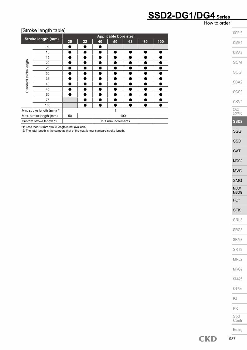
SSD2-DG1/DG4 SeriesHow to order
*1: Less than 10 mm stroke length is not available.*2: The total length is the same as that of the next longer standard stroke length.
Stroke length (mm)Applicable bore size
25 32 40 50 63 80 100
Sta
ndar
d st
roke
leng
th
5 10 15 20 25 30 35 40 45 50 75 100
Min. stroke length (mm) *1 1Max. stroke length (mm) 50 100Custom stroke length *2 In 1 mm increments
[Stroke length table] SCP*3
CMK2
CMA2
SCM
SCG
SCA2
SCS2
CKV2
CAV2/COVP/N2
SSD2
SSG
SSD
CAT
MDC2
MVC
SMG
MSD/MSDG
FC*
STK
SRL3
SRG3
SRM3
SRT3
MRL2
MRG2
SM‑25
ShkAbs
FJ
FK
SpdContr
Ending
987

Internal structure and parts list SSD2-DG1L/DG4L-25 to 50 (double acting/double rod/anti-spatter adherence/with switch)
SSD2-DG1/DG4-25 to 50 (double acting/double rod/anti-spatter adherence)
No. Part name Material Remarks No. Part name Material Remarks
1 Piston rod A ø25: Stainless steelø32 to ø50: Steel
Industrial chrome plating
8 Body Aluminum alloy Hard alumite
9 Piston packing Nitrile rubber
2 C type snap ring for hole Steel Zinc phosphate 10 Piston Aluminum alloy Chromate
3 Coil scraper Phosphor bronze11 Piston rod B ø25: Stainless steel
ø32 to ø50: SteelIndustrial chrome plating4 Lube keeping structure Special rubber G4 only
5 Rod metal gasket Nitrile rubber 12 Spacer Aluminum alloy ø25, ø32: Chromate
6 Rod metal Aluminum alloy Alumite 13 Magnet Plastic
7 Rod packing Nitrile rubber
SSD2-DG1/DG4 Series
Part nameKit No. Repair parts No.
Bore size (mm)ø25 SSD2-DG1-25K
3 5 7 9ø32 SSD2-DG1-32Kø40 SSD2-DG1-40Kø50 SSD2-DG1-50K
Repair parts l is t
1 3 4 2 6 7 5 12 13 10 118 9
1 3 4 2 6 7 5 8 10 119
SCP*3
CMK2
CMA2
SCM
SCG
SCA2
SCS2
CKV2
CAV2/COVP/N2
SSD2
SSG
SSD
CAT
MDC2
MVC
SMG
MSD/MSDG
FC*
STK
SRL3
SRG3
SRM3
SRT3
MRL2
MRG2
SM‑25
ShkAbs
FJ
FK
SpdContr
Ending
988

Internal structure and parts list SSD2-DG1L/DG4L-63 to 100 (double acting/double rod/anti-spatter adherence/with switch)
SSD2-DG1/DG4 SeriesInternal structure and parts list
SSD2-DG1/DG4-63 to 100 (double acting/double rod/anti-spatter adherence)
No. Part name Material Remarks No. Part name Material Remarks1 Piston rod A Steel Industrial chrome plating 8 Bush Oiles drymet
2 Coil scraper Phosphor bronze 9 Body Aluminum alloy Hard alumite
3 C type snap ring for hole Steel Zinc phosphate 10 Piston packing Nitrile rubber Chromate
4 Lube keeping structure Special rubber G4 only 11 Piston Aluminum alloy Chromate
5 Rod metal gasket Nitrile rubber 12 Piston rod B Steel Industrial chrome plating
6 Rod metal Aluminum alloy Chromate 13 Spacer Aluminum alloy Chromate
7 Rod packing Nitrile rubber 14 Magnet Plastic
Part nameKit No. Repair parts No.
Bore size (mm)ø63 SSD2-DG1-63K
2 5 7 10ø80 SSD2-DG1-80Kø100 SSD2-DG1-100K
Repair parts l is t
1 2 4 3 7 146 95 8 13 10 11 12
1 2 4 3 7 6 95 8 10 11 12
SCP*3
CMK2
CMA2
SCM
SCG
SCA2
SCS2
CKV2
CAV2/COVP/N2
SSD2
SSG
SSD
CAT
MDC2
MVC
SMG
MSD/MSDG
FC*
STK
SRL3
SRG3
SRM3
SRT3
MRL2
MRG2
SM‑25
ShkAbs
FJ
FK
SpdContr
Ending
989

SSD2-DG1/DG4 Series
Dimensions SSD2-DG1L/DG4L-25 (with switch)
SSD2-DG1/DG4-25 (without switch)
Rod end male thread
Code Without switch Dimensions with switchBore size (mm) A *1 B *1 A *1 B *1 FA FB RD *2 HD
ø25 59 49 69 59 31.5 17 20 21.5
*1 : To calculate A+ (2 x stroke length), B+ stroke length or 5+ stroke length when using a custom stroke length, apply the next longer standard stroke length (instead of the custom stroke length) to the stroke length value. Left and right projection dimensions of rod differ.
(Example) If the custom stroke length is 17 mm, apply the standard stroke length 20 mm.*2 : RD dimensions for custom stroke length differ from these dimensions according to the setting.*3 : For dimensions of individual accessories, refer to pages 1046 to 1049.
17.5 515
6
ø12
10 (width across flats)17 (width across flats)
M10×1.25
A + (2 × stroke length)
B + stroke length 5 + stroke length
HD
11
8-M6 depth 11ø5.5
RD
12
2-M6 depth 12
112-M5
5
A + (2 × stroke length)
B + stroke length 5 + stroke length
11
8-M6 depth 11ø5.5
12
112-M5
5
17
31.3
10
40 28
40
28
ø51
10
40 28
40
28
ø51
8-9 spot face depth 5.5Mounting hole
8-9 spot face depth 5.5Mounting hole
2-M6 depth 12
SCP*3
CMK2
CMA2
SCM
SCG
SCA2
SCS2
CKV2
CAV2/COVP/N2
SSD2
SSG
SSD
CAT
MDC2
MVC
SMG
MSD/MSDG
FC*
STK
SRL3
SRG3
SRM3
SRT3
MRL2
MRG2
SM‑25
ShkAbs
FJ
FK
SpdContr
Ending
990

SSD2-DG1/DG4 SeriesDouble acting/double rod
Dimensions SSD2-DG1L/DG4L-32 to 100 (with switch) Rod end male thread
Code Common dimensions with switch With T2YD switchBore size (mm)
M MM N OUA
UBWF
RD *2 HDG1 G4 G1 G4
ø32 14 16 34 4.5 5 10 23 h9 12 17 20.5 22
ø40 14 16 40 5 5 10 28 h9 12 17 23.5 27.5
ø50 17 20 50 7 5 10 35 h9 13 18 23.5 27.5
ø63 17 20 60 7 5 10 35 h9 13 18 24 28.5
ø80 22 25 77 6 5 10 43 h9 15 20 26.5 35
ø100 27 30 94 6.5 5 10 59 h9 17 22 30.5 40.5
*1 : To calculate A+ (2 x stroke length), B+ stroke length or WF+ stroke length when using a custom stroke length, apply the next longer standard stroke length (instead of the custom stroke length) to the stroke length value. Left and right projection dimensions of rod differ.
(Example) If the custom stroke length is 17 mm, apply the standard stroke length 20 mm.
*2 : RD dimensions for custom stroke length differ from these dimensions according to the setting.
*3 : For dimensions of individual accessories, refer to pages 1046 to 1049.
*4 : Dimensions in ( ) of codes A and B are for stroke lengths of more than 50 mm.
Code Without switch Common dimensions with switchBore size (mm)
A *1, *4
B *1, *4 A *1
B *1 C D EE F FA FB G H I J KA KKG1 G4 G1 G4
ø32 54.5(64.5) 64.5(74.5) 30.5(40.5) 64.5 74.5 40.5 8 8 Rc1/8 45 33.5 24 49.5 12.5 5.5 9 spot face depth 5.5 M6 depth 11 M8 depth 13
ø40 64(74) 74(84) 40(50) 74 84 50 12 12 Rc1/8 52 37 31 57 15 5.5 9 spot face depth 5.5 M6 depth 11 M8 depth 13
ø50 66.5(76.5) 76.5(86.5) 40.5(50.5) 76.5 86.5 50.5 10.5 10.5 Rc1/4 64 43 32 71 18 6.9 11 spot face depth 6.5 M8 depth 13 M10 depth 15
ø63 68(78) 78(88) 42(52) 78 88 52 13 13 Rc1/4 77 49.5 32 84 23 8.7 14 spot face depth 9 M10 depth 25 M10 depth 15
ø80 81(91) 91(101) 51(61) 91 101 61 16 16 Rc3/8 98 60 32 104 31 10.5 17 spot face depth 11 M12 depth 28 M16 depth 21
ø100 94.5(104.5) 104.5(114.5) 60.5(70.5) 104.5 114.5 70.5 23 23 Rc3/8 117 69.5 32 123.5 38 10.5 17.5 spot face depth 11 M12 depth 28 M20 depth 27
Codea’ c’ H kk’ M MM T
wfBore size (mm) G1 G4
ø32 23.5 20.5 22 M14×1.5 14 16 8 10 15
ø40 23.5 20.5 22 M14×1.5 14 16 8 10 15
ø50 28.5 26 27 M18×1.5 17 20 11 10 15
ø63 28.5 26 27 M18×1.5 17 20 11 10 15
ø80 35.5 32.5 32 M22×1.5 22 25 13 13 18
ø100 35.5 32.5 41 M26×1.5 27 30 16 13 18
Dimensions of rod end male thread part
SSD2-DG1/DG4-32 to 100 (without switch)
A + (2 × stroke length)
B + stroke length WF + stroke length
HD
D
8-KARD
øMM
KK
UA
WF
C
A + (2 × stroke length)
B + stroke length WF + stroke length
D
8-KA
øMM
øI
KK
WF
C
G F
F
N8-JMounting hole
NO
H
M
FA
FB
G F
F
N
NO
H
M
2-U
B
UA
8-JMounting hole
2-U
B
UA UA
a’c’T
wf
øMM
kk’Width across flats M
Width across flats H
øI
SCP*3
CMK2
CMA2
SCM
SCG
SCA2
SCS2
CKV2
CAV2/COVP/N2
SSD2
SSG
SSD
CAT
MDC2
MVC
SMG
MSD/MSDG
FC*
STK
SRL3
SRG3
SRM3
SRT3
MRL2
MRG2
SM‑25
ShkAbs
FJ
FK
SpdContr
Ending
991

Compact cylinder double acting single rod/environment-resistant scraper
SSD2-G5 Series Bore size: ø20/ø25/ø32/ø40/ø50/ø63/ø80/ø100
JIS symbol
Specifications
Item SSD2-G5SSD2-G5L (with switch)
Bore size mm ø20 ø25 ø32 ø40 ø50 ø63 ø80 ø100
Actuation Double acting
Working fluid Compressed air
Max. working pressure MPa 1.0 (≈150 psi, 10 bar)
Min. working pressure MPa 0.2 (≈29 psi, 2 bar) 0.15 (≈22 psi, 1.5 bar)
Proof pressure MPa 1.6 (≈230 psi, 16 bar)
Ambient temperature °C -10 (14°F) to 60 (140°F) (no freezing)
Port size M5 Rc1/8 (*1) Rc1/4 Rc3/8
Stroke tolerance mm +1.00
Working piston speed mm/s 50 to 500 50 to 300
Cushion None
Lubrication Not required (use turbine oil class 1 ISO VG32 if necessary for lubrication)
Allowable absorbed energy J 0.016 0.021 0.025 0.092 0.1 0.12 0.27 0.56
Custom stroke length SSD2-G5 Series
ItemStandard products
Standard stroke length body with spacerModel No. Refer to How to order.
DescriptionA spacer is added to the standard stroke length body to adjust the stroke length in 1 mm increments.
Stroke rangeBore size Stroke range20 to 25 1 to 4932 to 100 1 to 99
Example of model No.Model No.: SSD2-G5-32-38A +2 mm spacer is added to the SSD2-G5-32-40 standard cylinder to create 38 mm stroke length. B + stroke length is 73mm.
Stroke lengthBore size
(mm)Standard stroke
length (mm)Max. stroke length (mm)
Min. stroke length (mm)
ø20 5/10/15/20/25/30/35/40/45/50
50
1
ø25
ø32 5/10/15/20/25/30/35/40/45/50/75/100
100
ø40
ø50
10/15/20/25/30/35/40/45/50/75/100
ø63
ø80
ø100*1 : For the type with switch, refer to the table of switch mounting quantity and minimum
stroke length.*2 : The custom stroke length is available in 1 mm increments. The total length when using a
custom stroke length is the same as that when using the next longer standard stroke length.
Min. stroke length with switch (2 switches)
*1 : Less than 10 mm with the 2-color display, off-delay, AC magnetic field proof, T1* or T8* switch is not available.
*2 : Values in ( ) are for the type with 1 on rod side.
Bore size (mm) T0H/V / T5H/V T2H/V / T3H/V
ø20
5 5
ø25ø32ø40ø50ø63ø80ø100
*1: The ø32 bore size with a 5 mm stroke and without a switch has a port size of M5.
A + stroke length
B + stroke length
SCP*3
CMK2
CMA2
SCM
SCG
SCA2
SCS2
CKV2
CAV2/COVP/N2
SSD2
SSG
SSD
CAT
MDC2
MVC
SMG
MSD/MSDG
FC*
STK
SRL3
SRG3
SRM3
SRT3
MRL2
MRG2
SM‑25
ShkAbs
FJ
FK
SpdContr
Ending
992

SSD2-G5 SeriesSpecifications
Switch specifications (F type switch) 1-color/2-color display
ItemProximity 2-wire Proximity 3-wire Proximity 2-wire Proximity 3-wire
F2S F3S F2H/F2V F2YH/F2YV F3H/F3VF3PH/F3PV
(made to order)F3YH/F3YV
Applications Dedicated for programmable controller
For programmable controller, relay
Dedicated for programmable controller
For programmable controller, relay
Output method - NPN output - NPN output PNP output NPN outputPower supply voltage - 10 to 28 VDC - 10 to 28 VDC 4.5 to 28 VDC 10 to 28 VDCLoad voltage 10 to 30 VDC 30 VDC or less 10 to 30 VDC 24 VDC ±10% 30 VDC or lessLoad current 5 to 20 mA 50 mA or less 5 to 20 mA 50 mA or less
Indicator lamp LED(Lit when ON)
Yellow LED(Lit when ON)
Red/greenLED
(Lit when ON)
Yellow LED(Lit when ON)
Red/greenLED
(Lit when ON)Leakage current 1 mA or less 10 μA or less 1 mA or less 10 μA or lessWeight g 1 m:10 3 m:29
Switch specifications (T type switch) 1-color/2-color display/for AC magnetic field proof
ItemProximity 2-wire Proximity 2-wire Proximity 3-wire Reed 2-wire Proximity 2-wire
T1H/T1VT2H/T2V/
T2JH/T2JVT2YH/T2YV
T2WH/T2WV
T3H/T3V
T3PH/T3PV
T3YH/T3YV
T3WH/T3WV
T0H/T0V T5H/T5V T8H/T8VT2YD(*4)T2YDT
ApplicationsFor programmable
controller, relay, compact solenoid valve
Dedicated for programmable controller
For programmable controller, relay
For programmable controller, relay
For programmable controller, relay, IC circuit (no indicator
lamp), serial connection
For programmable controller, relay
Dedicated for programmable
controllerOutput method - NPN output PNP output NPN output NPN output -Pwr. supp. V. - 10 to 28 VDC -Load voltage 85 to 265 VAC 10 to 30 VDC 24 VDC ±10% 30 VDC or less 12/24 VDC 100/110 VAC 5/12/24 VDC 100/110 VAC 12/24 VDC 110 VAC 220 VAC 24 VDC ±10%Load current 5 to 100 mA 5 to 20 mA (*3) 100 mA or less 50 mA or less 5 to 50 mA 7 to 20 mA 50 mA or less 20 mA or less 5 to 50 mA 7 to 20 mA 7 to 10 mA 5 to 20 mA
Indicator lamp
LED(Lit when ON)
LED(Lit when ON)
Red/green LED
(Lit when ON)
Red/green LED
(Lit when ON)
LED(Lit when ON)
Yellow LED
(Lit when ON)
Red/green LED
(Lit when ON)
Red/green LED
(Lit when ON)
LED(Lit when ON)
Without indicator lamp
LED(Lit when ON)
Red/green LED
(Lit when ON)Leakage current
≤ 1 mA at 100 VAC, ≤ 2 mA at 200 VAC
1 mA or less 10 μA or less 0 mA 1 mA or less
Weight g1 m:333 m:875 m:142
1 m:183 m:495 m:80
1 m:333 m:875 m:142
1 m:183 m:495 m:80
1 m:183 m:495 m:80
1 m:333 m:875 m:142
1 m:183 m:495 m:80
1 m:18 3 m:49 5 m:801 m:333 m:875 m:142
1 m:613 m:1665 m:272
*1 : Refer to Ending Page 1 for detailed switch specifications and dimensions. *2 : Switches other than the above models, such as switches with connectors, are also available. Refer to Ending Page 1. *3 : The max. load current is 20 mA at 25°C. The current is lower than 20 mA if the operating ambient temperature around the switch is higher than 25˚C.
(5 to 10 mA at 60°C) *4 : Switch for AC magnetic field (T2YD/T2YDT) cannot be used in DC magnetic field. *5 : The F type switch uses a bend-resistant lead wire.
Bore size (mm)
Operating direction
Working pressure MPa0.15 0.2 0.3 0.4 0.5 0.6 0.7 0.8 0.9 1.0
ø20Push - 62.8 94.2 1.26×10² 1.57×10² 1.88×10² 2.20×10² 2.51×10² 2.83×10² 3.14×10²
Pull - 47.1 70.7 94.2 1.18×10² 1.41×10² 1.65×10² 1.88×10² 2.12×10² 2.36×10²
ø25Push - 98.2 1.47×10² 1.96×10² 2.45×10² 2.95×10² 3.44×10² 3.93×10² 4.42×10² 4.91×10²
Pull - 75.6 1.13×10² 1.51×10² 1.89×10² 2.27×10² 2.64×10² 3.02×10² 3.40×10² 3.78×10²
ø32Push - 1.61×10² 2.41×10² 3.22×10² 4.02×10² 4.83×10² 5.63×10² 6.43×10² 7.24×10² 8.04×10²
Pull - 1.21×10² 1.81×10² 2.41×10² 3.02×10² 3.62×10² 4.22×10² 4.83×10² 5.43×10² 6.03×10²
ø40Push - 2.51×10² 3.77×10² 5.03×10² 6.28×10² 7.54×10² 8.80×10² 1.01×10³ 1.13×10³ 1.26×10³
Pull - 2.11×10² 3.17×10² 4.22×10² 5.28×10² 6.33×10² 7.39×10² 8.44×10² 9.50×10² 1.06×10³
ø50Push - 3.93×10² 5.89×10² 7.85×10² 9.82×10² 1.18×10³ 1.37×10³ 1.57×10³ 1.77×10³ 1.96×10³
Pull - 3.30×10² 4.95×10² 6.60×10² 8.25×10² 9.90×10² 1.15×10³ 1.32×10³ 1.48×10³ 1.65×10³
ø63Push 4.68×10² 6.23×10² 9.35×10² 1.25×10³ 1.56×10³ 1.87×10³ 2.18×10³ 2.49×10³ 2.81×10³ 3.12×10³
Pull 4.20×10² 5.61×10² 8.41×10² 1.12×10³ 1.40×10³ 1.68×10³ 1.96×10³ 2.24×10³ 2.52×10³ 2.80×10³
ø80Push 7.54×10² 1.01×10³ 1.51×10³ 2.01×10³ 2.51×10³ 3.02×10³ 3.52×10³ 4.02×10³ 4.52×10³ 5.03×10³
Pull 6.80×10² 9.07×10² 1.36×10³ 1.81×10³ 2.27×10³ 2.72×10³ 3.17×10³ 3.63×10³ 4.08×10³ 4.54×10³
ø100Push 1.18×10³ 1.57×10³ 2.36×10³ 3.14×10³ 3.93×10³ 4.71×10³ 5.50×10³ 6.28×10³ 7.07×10³ 7.85×10³
Pull 1.07×10³ 1.43×10³ 2.14×10³ 2.86×10³ 3.57×10³ 4.29×10³ 5.00×10³ 5.72×10³ 6.43×10³ 7.15×10³
Theoretical thrust table (Unit: N)
Stroke length (mm) 5 10 15 20 25 30 35 40 45 50 75 100
Bore size (mm) No switch Switch No switch Switch No switch Switch No switch Switch No switch Switch No switch Switch No switch Switch No switch Switch No switch Switch No switch Switch No switch Switch No switch Switch
ø20 95 150 107 182 120 195 133 208 145 220 158 233 171 246 184 259 197 272 210 285 - - - -
ø25 131 222 146 237 162 253 178 269 194 285 209 300 225 316 241 332 257 348 272 363 - - - -
ø32 185 299 207 321 229 343 251 365 272 386 294 408 316 430 338 452 360 474 381 495 552 600 662 710
ø40 269 412 296 439 322 465 349 492 376 519 402 545 429 572 455 598 482 625 508 651 726 784 858 916
ø50 - - 476 670 518 712 560 754 602 796 645 839 687 881 729 923 771 965 813 1007 1160 1217 1370 1427
ø63 - - 703 982 758 1037 813 1092 868 1147 923 1202 999 1258 1074 1313 1150 1369 1144 1423 1332 1696 1709 1973
ø80 - - 1240 1653 1327 1740 1413 1826 1500 1908 1586 1990 1673 2082 1760 2173 1847 2265 1933 2346 2701 2754 3136 3211
ø100 - - 1879 2446 1993 2560 2106 2673 2220 2787 2334 2901 2448 3015 2561 3128 2675 3242 2789 3356 3857 3929 4424 4496
Cylinder weight table (the weight of the switches is when there are 2 cylinder switches.) (Unit: g)
SCP*3
CMK2
CMA2
SCM
SCG
SCA2
SCS2
CKV2
CAV2/COVP/N2
SSD2
SSG
SSD
CAT
MDC2
MVC
SMG
MSD/MSDG
FC*
STK
SRL3
SRG3
SRM3
SRT3
MRL2
MRG2
SM‑25
ShkAbs
FJ
FK
SpdContr
Ending
993

How to order
D Stroke length
Without switch (without magnet for switch)
A Model No.
B Bore size
I Accessory
SSD2-G5 Series
With switch (built-in magnet for switch)
20 IN5
20 R IN5
D Stroke length (mm)
Refer to the stroke length table on the following page.
Code DescriptionA Model No.SSD2-G5 Double acting/single rod/environment-resistant scraper (made-to-order product)
SSD2-G5L Double acting/single rod/environment-resistant scraper/switch (MTO)
B Bore size (mm)20 ø2025 ø2532 ø3240 ø4050 ø5063 ø6380 ø80
100 ø100
C Port threadBlank Rc thread/M5 thread
NN NPT thread (ø32 and over) (made-to-order product)GN G thread (ø32 and over) (made-to-order product)
* Lead wire lengthBlank 1 m (standard)
3 3 m (option)5 5 m (option) *5
F Switch quantityR 1 on rod sideH 1 on head sideD 2
G OptionBlank Rod end female thread
N Rod end male thread
H Mounting bracketBlank Without mounting bracket
LB Axial footCB Clevis bracket (pin and snap ring included)FA Rod side flangeFB Head side flange
I Accessory (available when rod end male thread “N” is selected)I Rod eyeY Rod clevis (pin and snap ring included)
E Switch model No.Lead wire Lead wire
Conta
ct Voltage Display Lead Bore sizeStraight L-shaped AC DC Line 20 25 32 40 50 63 80 100
- F2S*
Pro
xim
ity
1-color display
2-wire - F3S* 3-wire
F2H* F2V* 2-wire F3H* F3V* 3-wire
F3PH* F3PV* 1 color display (PNP output) (custom) 3-wire F2YH* F2YV*
2-color display2-wire
F3YH* F3YV* 3-wire T0H* T0V*
Ree
d 1-color display2-wire
T5H* T5V* Without indicator lamp T8H* T8V* 1-color display T1H* T1V*
Pro
xim
ity
1-color display
2-wire
T2H* T2V* T3H* T3V*
3-wire
T3PH* T3PV* 1-color display (PNP output) T2WH* T2WV*
2-color display2-wire
T2YH* T2YV* T3WH* T3WV*
3-wire
T3YH* T3YV* T2YD* - 2-color display
for AC magnetic field 2-wire
T2YDT* - T2JH* T2JV* 1-color display off-delay 2-wire
F Switch quantity
Precautions for model No. selection*1 : The T8* switch cannot be mounted on the ø20
to ø32 bore sizes.*2 : The mounting bracket is included at shipment. The WF/wf dimension of the cylinder for “LB”
and “FA” is set 10 mm longer than that of standard products. The number of the specified protruding dimension will be added at the end of the model No. printed on the metal plate on the body.
*3 : “I” and “Y” cannot be selected together.*4 : Switches are shipped with the product. Contact CKD if assembling before shipment is
necessary.*5 : F type switch cannot be selected.
[Example of model No.]SSD2-G5L-32-5-T0H-R-N-LB-IModel: Compact cylinder
Double acting/single rod/environment-resistant scraperB Bore size : ø32 mmC Port thread : Type of Rc threadD Stroke length : 5 mmE Switch model
No.: Reed switch T0HLead wire length 1 m
F Switch quantity : 1 on rod sideG Option : Rod end male threadH Mounting bracket : Axial footI Accessory : Rod eye
C Port thread
G Option
*2H Mounting bracket
*3
*1*4
E Switch model No.
SSD2-G5
SSD2-G5L
LB
LBT0H
SCP*3
CMK2
CMA2
SCM
SCG
SCA2
SCS2
CKV2
CAV2/COVP/N2
SSD2
SSG
SSD
CAT
MDC2
MVC
SMG
MSD/MSDG
FC*
STK
SRL3
SRG3
SRM3
SRT3
MRL2
MRG2
SM‑25
ShkAbs
FJ
FK
SpdContr
Ending
994

Stroke length (mm)Applicable bore size
20 25 32 40 50 63 80 100
Sta
ndar
d st
roke
leng
th
5 10 15 20 25 30 35 40 45 50 75
100 Min. stroke length (mm) *1 1Max. stroke length (mm) 50 100Custom stroke length *2 In 1 mm increments
*1 : Less than 5 mm for 1-color display switch and less than 10 mm for the 2-color display, off-delay, AC magnetic field proof, T1* or T8* switch are not available.
Refer to page 992 for the min. stroke length with switch.*2 : The total length when using a custom stroke length is the same as that when using the next longer standard
stroke length.
Bore size (mm)ø20 ø25 ø32 ø40 ø50 ø63 ø80
Mounting bracketFoot (LB) SSD2-LB-20 SSD2-LB-25 SSD2-LB-32 SSD2-LB-40 SSD2-LB-50 SSD2-LB-63 SSD2-LB-80Flange (FA/FB) SSD2-FA-20 SSD2-FA-25 SSD2-FA-32 SSD2-FA-40 SSD2-FA-50 SSD2-FA-63 SSD2-FA-80Clevis bracket (CB) SSD2-CB-20 SSD2-CB-25 SSD2-CB-32 SSD2-CB-40 SSD2-CB-50 SSD2-CB-63 SSD2-CB-80
Bore size (mm)ø100
Mounting bracketFoot (LB) SSD2-LB-100Flange (FA/FB) SSD2-FA-100Clevis bracket (CB) SSD2-CB-100
SSD2-G5 SeriesHow to order
How to order switch
Switch model No. (Item E on page 994)
*1: The foot mounting bracket is provided as 2 pcs./set.
[Stroke length table]
How to order mounting bracket
SW T0H
SCP*3
CMK2
CMA2
SCM
SCG
SCA2
SCS2
CKV2
CAV2/COVP/N2
SSD2
SSG
SSD
CAT
MDC2
MVC
SMG
MSD/MSDG
FC*
STK
SRL3
SRG3
SRM3
SRT3
MRL2
MRG2
SM‑25
ShkAbs
FJ
FK
SpdContr
Ending
995

Internal structure and parts list (ø20 to ø50)
Main parts listNo. Part name Material Remarks No. Part name Material Remarks
1 Piston rod Stainless steel Industrial chrome plating 9 Body Aluminum alloy Hard alumite
2 C type snap ring Steel Zinc phosphate 10 Spacer Aluminum alloy Chromate
3 Rod metal 1 Special aluminum Alumite 11 Magnet Plastic
4 Scraper Nitrile rubber 12 Piston Aluminum alloy Chromate
5 Lube keeping structure Special rubber 13 Piston packing Nitrile rubber
6 Rod metal Special aluminum Alumite 14 Cover Stainless steel
7 Rod metal gasket Nitrile rubber
8 Rod packing Nitrile rubber
SSD2-G5L-20, 25 (double acting/environment-resistant scraper/with switch)
SSD2-G5-20, 25 (double acting/environment-resistant scraper)
Repair parts listPart name
Kit No. Repair parts No.Bore size (mm)
ø20 SSD2-G5-20K4 5 7 8 13
ø25 SSD2-G5-25K
SSD2-G5 Series
1 2 4 3 5 7 8 6 9 10 11 12 13 14
1 2 4 3 5 7 8 6 9 12 13 14
SCP*3
CMK2
CMA2
SCM
SCG
SCA2
SCS2
CKV2
CAV2/COVP/N2
SSD2
SSG
SSD
CAT
MDC2
MVC
SMG
MSD/MSDG
FC*
STK
SRL3
SRG3
SRM3
SRT3
MRL2
MRG2
SM‑25
ShkAbs
FJ
FK
SpdContr
Ending
996

Internal structure and parts list (ø63 to ø100)
Main parts listNo. Part name Material Remarks No. Part name Material Remarks
1 Piston rod Steel Industrial chrome plating 8 Rod packing Nitrile rubber
2 C type snap ring Steel Zinc phosphate 9 Body Aluminum alloy Hard alumite
3 Rod metal 1ø32 to ø50: Special aluminum
ø63 to ø100: Aluminum alloy
ø32 to ø50: Alumite
ø63 to ø100: Chromate
10 Spacer Aluminum alloy Chromate
11 Magnet Plastic
4 Scraper Nitrile rubber 12 Piston Aluminum alloy Chromate
5 Lube keeping structure Special rubber 13 Piston packing Nitrile rubber
6 Rod metalø32 to ø50: Special aluminum
ø63 to ø100: Aluminum alloy
ø32 to ø50: Alumite
ø63 to ø100: Chromate
14 Cover Aluminum alloy Alumite
15 Bush Oiles drymet
7 Rod metal gasket Nitrile rubber
Repair parts listPart name
Kit No. Repair parts No.Bore size (mm)
ø32 SSD2-G5-32K
4 5 7 8 13
ø40 SSD2-G5-40Kø50 SSD2-G5-50Kø63 SSD2-G5-63Kø80 SSD2-G5-80K
ø100 SSD2-G5-100K
SSD2-G5 SeriesInternal structure and parts list
SSD2-G5L-32 to 50 (double acting/environment-resistant scraper/with switch)
SSD2-G5L-63 to 100 (double acting/environment-resistant scraper/with switch)
SSD2-G5-32 to 50 (double acting/environment-resistant scraper)
SSD2-G5-63 to 100 (double acting/environment-resistant scraper)
1 2 4 3 5 7 8 6 9 10 11 12 13 14 1 2 4 3 5 7 6 8 9 10 11 13 12 14
1 2 4 3 5 7 8 6 9 12 13 14 10 1 4 2 3 5 7 6 8 15 9 13 12 14 10
50 st or less Over 50 st 50 st or less Over 50 st
SCP*3
CMK2
CMA2
SCM
SCG
SCA2
SCS2
CKV2
CAV2/COVP/N2
SSD2
SSG
SSD
CAT
MDC2
MVC
SMG
MSD/MSDG
FC*
STK
SRL3
SRG3
SRM3
SRT3
MRL2
MRG2
SM‑25
ShkAbs
FJ
FK
SpdContr
Ending
997
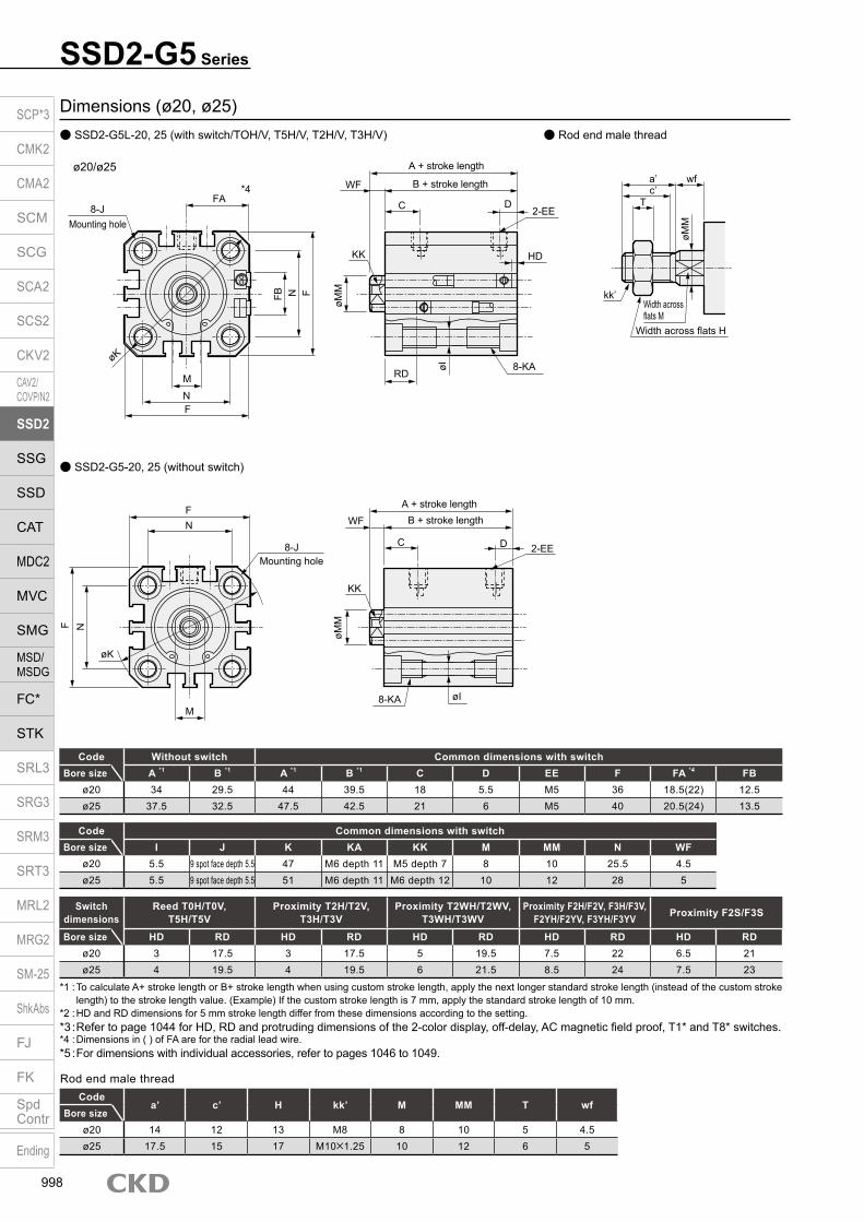
SSD2-G5 Series
Dimensions (ø20, ø25)
Code Without switch Common dimensions with switchBore size A *1 B *1 A *1 B *1 C D EE F FA *4 FB
ø20 34 29.5 44 39.5 18 5.5 M5 36 18.5(22) 12.5ø25 37.5 32.5 47.5 42.5 21 6 M5 40 20.5(24) 13.5
Switch dimensions
Reed T0H/T0V,T5H/T5V
Proximity T2H/T2V,T3H/T3V
Proximity T2WH/T2WV,T3WH/T3WV
Proximity F2H/F2V, F3H/F3V,F2YH/F2YV, F3YH/F3YV Proximity F2S/F3S
Bore size HD RD HD RD HD RD HD RD HD RDø20 3 17.5 3 17.5 5 19.5 7.5 22 6.5 21ø25 4 19.5 4 19.5 6 21.5 8.5 24 7.5 23
Codea’ c’ H kk’ M MM T wf
Bore sizeø20 14 12 13 M8 8 10 5 4.5ø25 17.5 15 17 M10×1.25 10 12 6 5
Rod end male thread
*1 : To calculate A+ stroke length or B+ stroke length when using custom stroke length, apply the next longer standard stroke length (instead of the custom stroke length) to the stroke length value. (Example) If the custom stroke length is 7 mm, apply the standard stroke length of 10 mm.
*2 : HD and RD dimensions for 5 mm stroke length differ from these dimensions according to the setting.*3 : Refer to page 1044 for HD, RD and protruding dimensions of the 2-color display, off-delay, AC magnetic field proof, T1* and T8* switches.*4 : Dimensions in ( ) of FA are for the radial lead wire.*5 : For dimensions with individual accessories, refer to pages 1046 to 1049.
Code Common dimensions with switchBore size I J K KA KK M MM N WF
ø20 5.5 9 spot face depth 5.5 47 M6 depth 11 M5 depth 7 8 10 25.5 4.5ø25 5.5 9 spot face depth 5.5 51 M6 depth 11 M6 depth 12 10 12 28 5
ø20/ø25
SSD2-G5L-20, 25 (with switch/TOH/V, T5H/V, T2H/V, T3H/V) Rod end male thread
SSD2-G5-20, 25 (without switch)
F
8-JMounting hole
F N
M
N
øK
øMM
WF
KK
øI
C D
8-KA
2-EE
A + stroke lengthB + stroke length
*4
8-JMounting hole
FA
øK
M
NF
FB N F
øMM
WF
KK
RD
D
HD
2-EE
8-KAøI
A + stroke length
B + stroke length a’c’
T
wf
øMM
kk’Width across flats M
Width across flats H
C
SCP*3
CMK2
CMA2
SCM
SCG
SCA2
SCS2
CKV2
CAV2/COVP/N2
SSD2
SSG
SSD
CAT
MDC2
MVC
SMG
MSD/MSDG
FC*
STK
SRL3
SRG3
SRM3
SRT3
MRL2
MRG2
SM‑25
ShkAbs
FJ
FK
SpdContr
Ending
998

SSD2-G5 SeriesDimensions
Code Without switch Common dimensions with switchBore size A *1 B *1 A *1 B *1 C *7 D *7 EE *8 F FA *4 FB G H
ø32 40(50) 33(43) 50 43 18(20) 8(5.5) Rc1/8 45 23(26.5) 20.5 49.5 12.5ø40 46.5(56.5) 39.5(49.5) 56.5 49.5 22(21.5) 8.5(8) Rc1/8 52 26.5(30) 27.5 57 15ø50 48.5(58.5) 40.5(50.5) 58.5 50.5 20.5 10.5 Rc1/4 64 32.5(36) 28.5 71 18ø63 54(64) 46(56) 64 56 23 11 Rc1/4 77 39(42.5) 28.5 84 23ø80 63.5(73.5) 53.5(63.5) 73.5 63.5 26 13 Rc3/8 98 49.5(53) 28.5 104 31
ø100 75(85) 63(73) 85 73 33 15 Rc3/8 117 59(62.5) 28.5 123.5 38
Switch dimensions Reed T0H/T0V, T5H/T5V Proximity T2H/T2V, T3H/T3V Proximity T2WH/T2WV, T3WH/T3WVBore size HD RD HD RD HD RD
ø32 4 19.5 4 19.5 6 21.5ø40 7 22 7 22 8.5 23.5ø50 7.5 22.5 7.5 22.5 9 24ø63 12.5 23 12.5 23 14 24.5ø80 17.5 25.5 17.5 25.5 19 27
ø100 23 29.5 23 29.5 24.5 31
Codea’ c’ H kk’ M MM T wf
Bore sizeø32 23.5 20.5 22 M14×1.5 14 16 8 5ø40 23.5 20.5 22 M14×1.5 14 16 8 5ø50 28.5 26 27 M18×1.5 17 20 11 5ø63 28.5 26 27 M18×1.5 17 20 11 5ø80 35.5 32.5 32 M22×1.5 22 25 13 8
ø100 35.5 32.5 41 M26×1.5 27 30 16 8
Rod end male thread
*1 : To calculate A+ stroke length or B+ stroke length when using custom stroke length, apply the next longer standard stroke length (instead of the custom stroke length) to the stroke length value. (Example) If the custom stroke length is 7 mm, apply the standard stroke length of 10 mm.
*2 : HD and RD dimensions for 5 mm stroke length differ from these dimensions according to the setting.
*3 : Refer to page 1044 for HD, RD and protruding dimensions of the 2-color display, off-delay, AC magnetic field proof, T1* and T8* switches.
*4: Dimensions in ( ) of FA are for the radial lead wire.*5 : For dimensions of individual accessories, refer to
pages 1046 to 1049.*6 : Dimensions in ( ) of codes A and B are for stroke lengths of more than 50 mm.*7 : Dimensions in ( ) of codes C and D are when the value is
for a 5 mm stroke without switch.*8: The ø32 bore size with a 5 mm stroke and without a switch
has a port size of M5.
Code Common dimensions with switchBore size I J K KA KK M MM N O WF
ø32 5.5 9 spot face depth 5.5 60 M6 depth 11 M8 depth 13 14 16 34 4.5 7ø40 5.5 9 spot face depth 5.5 69 M6 depth 11 M8 depth 13 14 16 40 5 7ø50 6.9 11 spot face depth 6.5 86 M8 depth 13 M10 depth 15 17 20 50 7 8ø63 8.7 14 spot face depth 9 103 M10 depth 25 M10 depth 15 17 20 60 7 8ø80 10.5 17.5 spot face depth 11 132 M12 depth 28 M16 depth 21 22 25 77 6 10
ø100 10.5 17.5 spot face depth 11 156 M12 depth 28 M20 depth 27 27 30 94 6.5 12
Dimensions SSD2-G5L-32 to 100 (with switch/TOH/V, T5H/V, T2H/V, T3H/V) Rod end male thread
SSD2-G5-32 to 100 (without switch)
a’c’
T
wf
øMM
kk’Width across flats M
Width across flats H
*4
øK
G N
M
N
OF FB
FA
F
H8-J
Mounting hole
øMM
WF
KK
RD
C D
HD
2-EE
8-KAøI
A + stroke lengthB + stroke length
øK
øMM
WF
KK
C D 2-EE
8-KA øI
A + stroke lengthB + stroke length
F
M
N
ON
F
H8-J
Mounting hole
GSCP*3
CMK2
CMA2
SCM
SCG
SCA2
SCS2
CKV2
CAV2/COVP/N2
SSD2
SSG
SSD
CAT
MDC2
MVC
SMG
MSD/MSDG
FC*
STK
SRL3
SRG3
SRM3
SRT3
MRL2
MRG2
SM‑25
ShkAbs
FJ
FK
SpdContr
Ending
999

Dimensions with mounting bracket Axial foot (LB) SSD2-G5(L)-20 to 100 -LB
Clevis bracket (CB) SSD2-G5(L)-20 to 100 -CB
· ø20/ø25
· ø20/ø25
· ø32 to ø100
· ø32 to ø100
SSD2-G5 Series
Code Common dimensions Female thread Male threadBore size
(mm) AC CA CB CC CD D E G H MR N UB WF Without switch With switch a’ wf Without switch With switchA B CJ A B CJ A B CJ A B CJ
ø20 - 20 8.2 12 8 5 36 M6×16 C4 - 25.5 16 4.5 61 29.5 52 71 39.5 62 14 4.5 75 29.5 52 85 39.5 62ø25 - 24 10.2 14 10 5 40 M6×16 C5 - 28 20 5 67.5 32.5 57.5 77.5 42.5 67.5 17.5 5 85 32.5 57.5 95 42.5 67.5ø32 4.5 - 18.2 14 10 5 45 M6×16 - 10 34 36 7 70 33 60 80 43 70 23.5 5 91.5 33 58 101.5 43 68ø40 5 - 18.2 14 10 6 52 M6×16 - 10 40 36 7 78.5 39.5 68.5 88.5 49.5 78.5 23.5 5 100 39.5 66.5 110 49.5 76.5ø50 6 - 22.2 20 14 7 64 M8×20 - 14 50 44 8 90.5 40.5 76.5 100.5 50.5 86.5 28.5 5 116 40.5 73.5 126 50.5 83.5ø63 7 - 22.2 20 14 8 77 M10×25 - 14 60 44 8 98 46 84 108 56 94 28.5 5 123.5 46 81 133.5 56 91ø80 9 - 28.2 27 18 10 98 M12×40 - 18 77 56 10 119.5 53.5 101.5 129.5 63.5 111.5 35.5 8 153 53.5 99.5 163 63.5 109.5
ø100 12 - 32.2 31 22 13 117 M12×40 - 22 94 64 12 142 63 120 152 73 130 35.5 8 173.5 63 116 183.5 73 126
Code Common dimensions Female thread Male threadBore size
(mm) AB AD AE AG AH AK AT AU G N TR TS M LF WF Without switch With switch a’ wf Without switch With switchA B CJ A B CJ A B CJ A B CJ
ø20 7 - - 42 24 15 3.2 9.2 M6×16 25.5 48 62 7.2 20.5 14.5 51.2 29.5 17.5 61.2 39.5 27.5 14 14.5 65.2 29.5 17.5 75.2 39.5 27.5ø25 7 - - 46 26 16.5 3.2 10.7 M6×16 28 52 66 7.2 22.5 15 54.7 32.5 17.5 64.7 42.5 27.5 17.5 15 72.2 32.5 17.5 82.2 42.5 27.5ø32 7 18.5 13 57 30 17 3.2 11.2 M6×16 34 57 71 7.2 25 17 57.2 33 17 67.2 43 27 23.5 15 78.7 33 17 88.7 43 27ø40 7 18 13 64 33 18.2 3.2 11.2 M6×16 40 64 78 7.2 25 17 63.7 39.5 23.5 73.7 49.5 33.5 23.5 15 85.2 39.5 23.5 95.2 49.5 33.5ø50 9 22 14 78 39 22.7 3.2 14.7 M8×20 50 79 95 8.2 29.5 18 66.7 40.5 17.5 76.7 50.5 27.5 28.5 15 92.2 40.5 17.5 102.2 50.5 27.5ø63 11 26 16 91.5 46 25.2 3.2 16.2 M10×25 60 95 113 9.2 31 18 73.2 46 20 83.2 56 30 28.5 15 98.7 46 20 108.7 56 30ø80 13 31.5 20.5 114 59 30.5 4.5 19.5 M12×40 77 118 140 11.5 35 20 85 53.5 23.5 95 63.5 33.5 35.5 18 118.5 53.5 23.5 128.5 63.5 33.5
ø100 13 35 24 136 71 35.5 6 23 M12×40 94 137 162 13 39 22 98 63 29 108 73 39 35.5 18 129.5 63 29 139.5 73 39
N
AG N
TRTS
AT
AH
4-øAB
WFA + stroke length
B + stroke length M
AUAK
Low head hexagon socket bolt 8-G
LX + stroke length
NTRTS
4-øAB
AD
AE AT A
H
A + stroke lengthB + stroke lengtha’ wf
LFLF
A + stroke lengthRod end male thread
B + stroke lengtha’ wf
LX + stroke length
A + stroke lengthB + stroke length
Low head hexagon socket bolt 4-G
LF
WF
AUAK
M
Rod end male thread
AG
LF
NN
WF
A + stroke lengthB + stroke lengtha’ wf
A + stroke lengthRod end male thread
B + stroke lengtha’ wf
A + stroke lengthB + stroke lengthWF
Rod end male thread
A + stroke lengthB + stroke length
H
CJ + stroke lengthMounting bolt 4-C
N
E
E
CC
UBD
øCA
CD H10
CJ + stroke lengthCJ + stroke length
CJ + stroke length
CC
UBD
NE
E
CD H10
Mounting bolt 4-GAC
R MR
CB+ 0.2 0
CB+ 0.2 0
SCP*3
CMK2
CMA2
SCM
SCG
SCA2
SCS2
CKV2
CAV2/COVP/N2
SSD2
SSG
SSD
CAT
MDC2
MVC
SMG
MSD/MSDG
FC*
STK
SRL3
SRG3
SRM3
SRT3
MRL2
MRG2
SM‑25
ShkAbs
FJ
FK
SpdContr
Ending
1000

Dimensions with mounting bracket Rod side flange (FA) SSD2-G5(L)-20 to 100 -FA
Head side flange (FB) SSD2-G5(L)-20 to 100 -FB
· ø20/ø25
· ø20/ø25
· ø32 to ø100
· ø32 to ø100
SSD2-G5 SeriesDimensions with mounting bracket
Code Common dimensions Female thread Male threadBore size
(mm) FC FD FH FL FM FT N G WF Without switch With switch a’ wf Without switch With switchA B A B A B A B
ø20 - 6.6 39 48 60 8 25.5 M6×16 4.5 42 29.5 52 39.5 14 4.5 56 29.5 66 39.5ø25 - 6.6 42 52 64 8 28 M6×16 5 45.5 32.5 55.5 42.5 17.5 5 63 32.5 73 42.5ø32 34 5.5 48 56 65 8 34 M6×16 7 48 33 58 43 23.5 5 69.5 33 79.5 43ø40 40 5.5 54 62 72 8 40 M6×16 7 54.5 39.5 64.5 49.5 23.5 5 76 39.5 86 49.5ø50 50 6.6 67 76 89 9 50 M8×20 8 57.5 40.5 67.5 50.5 28.5 5 83 40.5 93 50.5ø63 60 9 80 92 108 9 60 M10×25 8 63 46 73 56 28.5 5 88.5 46 98.5 56ø80 77 11 99 116 134 11 77 M12×40 10 74.5 53.5 84.5 63.5 35.5 8 108 53.5 118 63.5ø100 94 11 117 136 154 11 94 M12×40 12 86 63 96 73 35.5 8 117.5 63 127.5 73
Code Common dimensions Female thread Male threadBore size
(mm) FC FD FH FL FM FT N G WF Without switch With switch a’ wf Without switch With switchA B A B A B A B
ø20 - 6.6 39 48 60 8 25.5 M6×16 14.5 44 29.5 54 39.5 14 14.5 58 29.5 68 39.5ø25 - 6.6 42 52 64 8 28 M6×16 15 47.5 32.5 57.5 42.5 17.5 15 65 32.5 75 42.5ø32 34 5.5 48 56 65 8 34 M6×16 17 50 33 60 43 23.5 15 71.5 33 81.5 43ø40 40 5.5 54 62 72 8 40 M6×16 17 56.5 39.5 66.5 49.5 23.5 15 78 39.5 88 49.5ø50 50 6.6 67 76 89 9 50 M8×20 18 58.5 40.5 68.5 50.5 28.5 15 84 40.5 94 50.5ø63 60 9 80 92 108 9 60 M10×25 18 64 46 74 56 28.5 15 89.5 46 99.5 56ø80 77 11 99 116 134 11 77 M12×40 20 73.5 53.5 83.5 63.5 35.5 18 107 53.5 117 63.5ø100 94 11 117 136 154 11 94 M12×40 22 85 63 95 73 35.5 18 116.5 63 126.5 73
A + stroke lengthB + stroke length
FM
NFH
N
2-FD
Mounting bolt 4-GHexagon socket button head bolt
Rod end male thread
FT
A + stroke lengthB + stroke length
FTa’ wf
Rod end male thread
A + stroke lengthB + stroke length
A + stroke lengthB + stroke lengtha’ wfFT
FTWFFL
FH FC
FM
NFL
4-FD
Mounting bolt 4-Gø32 to ø63: Hexagon socket button head boltø80/ø100: Special bolt
WF
N
FM
FH
WF
Mounting bolt 4-GHexagon socket button head bolt
FH FC
A + stroke lengthB + stroke lengtha’ wf FT
A + stroke length
Rod end male thread
B + stroke lengtha’ wf
A + stroke lengthB + stroke lengthFL WF
FT
Rod end male thread
A + stroke length
B + stroke length FT N
2-FD
4-FDFLN
Mounting bolt 4-G
FM
FT
ø32 to ø63: Hexagon socket button head boltø80/ø100: Special bolt
SCP*3
CMK2
CMA2
SCM
SCG
SCA2
SCS2
CKV2
CAV2/COVP/N2
SSD2
SSG
SSD
CAT
MDC2
MVC
SMG
MSD/MSDG
FC*
STK
SRL3
SRG3
SRM3
SRT3
MRL2
MRG2
SM‑25
ShkAbs
FJ
FK
SpdContr
Ending
1001

Compact cylinder double acting/single rod/high load/environment-resistant scraper
SSD2-KG5 Series Bore size: ø20/ø25/ø32/ø40/ø50/ø63/ø80/ø100
JIS symbol
SpecificationsItem SSD2-KG5
SSD2-KG5L (with switch)Bore size mm ø20 ø25 ø32 ø40 ø50 ø63 ø80 ø100Actuation Double actingWorking fluid Compressed airMax. working pressure MPa 1.0 (≈150 psi, 10 bar)Min. working pressure MPa 0.2 (≈29 psi, 2 bar) 0.15 (≈22 psi, 2 bar)Proof pressure MPa 1.6 (≈230 psi, 16 bar)Ambient temperature °C -10 (14°F) to 60 (140°F) (no freezing)Port size M5 Rc1/8 Rc1/4 Rc3/8Stroke tolerance mm +2.0
0
Working piston speed mm/s 50 to 500 50 to 300Cushion Rubber cushionLubrication Not required (use turbine oil class 1 ISO VG32 if necessary for lubrication)Allowable absorbed energy J 0.16 0.16 0.40 0.63 0.98 1.56 2.51 3.92
Stroke length
*4 : When using the type with switch, refer to the table of the min. stroke length with switch.
Bore size (mm)
Standard stroke length (mm)
Max. stroke length (mm)
Min. stroke length (mm)
ø20 5/10/15/20/25/30/35/40/45/50
50
1
ø25
ø32 5/10/15/20/25/30/35/40/45/50/75/100
100
ø40
ø50
10/15/20/25/30/35/40/45/50/75/100
ø63ø80ø100
Custom stroke length SSD2-KG5 Series
ItemStandard products
Standard stroke length body with spacerModel No. Refer to How to order.
DescriptionA spacer is added to the standard stroke length body to adjust the stroke length in 1 mm increments.
Stroke rangeBore size Stroke range20 to 25 1 to 4932 to 100 1 to 99
Example of model No.Model No.: SSD2-KG5-32-38A +2 mm spacer is added to the SSD2-KG5-32-40 standard cylinder to create 38 mm stroke length. B + stroke length is 83mm.
Min. stroke length with switch (2 switches)
*1 : Less than 10 mm with the 2-color display, off-delay, AC magnetic field proof, T1* or T8* switch is not available.
Bore size (mm) T0H/V / T5H/V T2H/V / T3H/V
ø20
5 5
ø25ø32ø40ø50ø63ø80ø100
A + stroke length
B + stroke length
SCP*3
CMK2
CMA2
SCM
SCG
SCA2
SCS2
CKV2
CAV2/COVP/N2
SSD2
SSG
SSD
CAT
MDC2
MVC
SMG
MSD/MSDG
FC*
STK
SRL3
SRG3
SRM3
SRT3
MRL2
MRG2
SM‑25
ShkAbs
FJ
FK
SpdContr
Ending
1002

SSD2-KG5 SeriesSpecifications
Switch specifications (F type switch) 1-color/2-color display
ItemProximity 2-wire Proximity 3-wire Proximity 2-wire Proximity 3-wire
F2S F3S F2H/F2VF2YH/F2YV
F3H/F3VF3PH/F3PV
(made to order)F3YH/F3YV
Applications Dedicated for programmable controller
For programmable controller, relay
Dedicated for programmable controller
For programmable controller, relay
Output method - NPN output - NPN output PNP output NPN outputPower supply voltage - 10 to 28 VDC - 10 to 28 VDC 4.5 to 28 VDC 10 to 28 VDCLoad voltage 10 to 30 VDC 30 VDC or less 10 to 30 VDC 24 VDC ±10% 30 VDC or lessLoad current 5 to 20 mA 50 mA or less 5 to 20 mA 50 mA or less
Indicator lamp LED(Lit when ON)
Yellow LED(Lit when ON)
Red/greenLED
(Lit when ON)
Yellow LED(Lit when ON)
Red/greenLED
(Lit when ON)Leakage current 1 mA or less 10 μA or less 1 mA or less 10 μA or lessWeight g 1 m:10 3 m:29
Switch specifications (T type switch) 1-color/2-color display/for AC magnetic field proof
ItemProximity 2-wire Proximity 2-wire Proximity 3-wire Reed 2-wire Proximity 2-wire
T1H/T1V
T2H/T2V/T2JH/T2JV
T2YH/T2YV
T2WH/T2WV
T3H/T3V
T3PH/T3PV
T3YH/T3YV
T3WH/T3WV
T0H/T0V T5H/T5V T8H/T8VT2YD(*4)T2YDT
ApplicationsFor programmable
controller, relay, compact solenoid valve
Dedicated for programmable controller
For programmable controller, relay
For programmable controller, relay
For programmable controller, relay, IC circuit (no indicator
lamp), serial connection
For programmable controller, relay
Dedicated for programmable
controllerOutput method - NPN output PNP output NPN output NPN output -Pwr. supp. V. - 10 to 28 VDC -Load voltage 85 to 265 VAC 10 to 30 VDC 24 VDC ±10% 30 VDC or less 12/24 VDC 100/110 VAC 5/12/24 VDC 100/110 VAC 12/24 VDC 110 VAC 220 VAC 24 VDC ±10%Load current 5 to 100 mA 5 to 20 mA (*3) 100 mA or less 50 mA or less 5 to 50 mA 7 to 20 mA 50 mA or less 20 mA or less 5 to 50 mA 7 to 20 mA 7 to 10 mA 5 to 20 mA
Indicator lamp
LED(Lit when ON)
LED(Lit when ON)
Red/green LED
(Lit when ON)
Red/green LED
(Lit when ON)
LED(Lit when ON)
Yellow LED
(Lit when ON)
Red/green LED
(Lit when ON)
Red/green LED
(Lit when ON)
LED(Lit when ON)
Without indicator lamp
LED(Lit when ON)
Red/green LED
(Lit when ON)Leakage current
≤ 1 mA at 100 VAC, ≤ 2 mA at 200 VAC
1 mA or less 10 μA or less 0 mA1 mA or
less
Weight g1 m:333 m:875 m:142
1 m:183 m:495 m:80
1 m:333 m:875 m:142
1 m:183 m:495 m:80
1 m:183 m:495 m:80
1 m:333 m:875 m:142
1 m:183 m:495 m:80
1 m:18 3 m:49 5 m:801 m:333 m:875 m:142
1 m:613 m:1665 m:272
*1 : Refer to Ending Page 1 for detailed switch specifications and dimensions. *2 : Switches other than the above models, such as switches with connectors, are also available. Refer to Ending Page 1. *3 : The max. load current is 20 mA at 25°C. The current is lower than 20 mA if the operating ambient temperature around the switch is higher than 25˚C.
(5 to 10 mA at 60°C) *4 : Switch for AC magnetic field (T2YD/T2YDT) cannot be used in DC magnetic field. *5 : The F type switch uses a bend-resistant lead wire.
Bore size (mm)
Operating direction
Working pressure MPa0.15 0.2 0.3 0.4 0.5 0.6 0.7 0.8 0.9 1.0
ø20Push - 62.8 94.2 1.26×10² 1.57×10² 1.88×10² 2.20×10² 2.51×10² 2.83×10² 3.14×10²
Pull - 47.1 70.7 94.2 1.18×10² 1.41×10² 1.65×10² 1.88×10² 2.12×10² 2.36×10²
ø25Push - 98.2 1.47×10² 1.96×10² 2.45×10² 2.95×10² 3.44×10² 3.93×10² 4.42×10² 4.91×10²
Pull - 75.6 1.13×10² 1.51×10² 1.89×10² 2.27×10² 2.64×10² 3.02×10² 3.40×10² 3.78×10²
ø32Push - 1.61×10² 2.41×10² 3.22×10² 4.02×10² 4.83×10² 5.63×10² 6.43×10² 7.24×10² 8.04×10²
Pull - 1.21×10² 1.81×10² 2.41×10² 3.02×10² 3.62×10² 4.22×10² 4.83×10² 5.43×10² 6.03×10²
ø40Push - 2.51×10² 3.77×10² 5.03×10² 6.28×10² 7.54×10² 8.80×10² 1.01×10³ 1.13×10³ 1.26×10³
Pull - 2.11×10² 3.17×10² 4.22×10² 5.28×10² 6.33×10² 7.39×10² 8.44×10² 9.50×10² 1.06×10³
ø50Push - 3.93×10² 5.89×10² 7.85×10² 9.82×10² 1.18×10³ 1.37×10³ 1.57×10³ 1.77×10³ 1.96×10³
Pull - 3.30×10² 4.95×10² 6.60×10² 8.25×10² 9.90×10² 1.15×10³ 1.32×10³ 1.48×10³ 1.65×10³
ø63Push 4.68×10² 6.23×10² 9.35×10² 1.25×10³ 1.56×10³ 1.87×10³ 2.18×10³ 2.49×10³ 2.81×10³ 3.12×10³
Pull 4.20×10² 5.61×10² 8.41×10² 1.12×10³ 1.40×10³ 1.68×10³ 1.96×10³ 2.24×10³ 2.52×10³ 2.80×10³
ø80Push 7.54×10² 1.01×10³ 1.51×10³ 2.01×10³ 2.51×10³ 3.02×10³ 3.52×10³ 4.02×10³ 4.52×10³ 5.03×10³
Pull 6.80×10² 9.07×10² 1.36×10³ 1.81×10³ 2.27×10³ 2.72×10³ 3.17×10³ 3.63×10³ 4.08×10³ 4.54×10³
ø100Push 1.18×10³ 1.57×10³ 2.36×10³ 3.14×10³ 3.93×10³ 4.71×10³ 5.50×10³ 6.28×10³ 7.07×10³ 7.85×10³
Pull 1.07×10³ 1.43×10³ 2.14×10³ 2.86×10³ 3.57×10³ 4.29×10³ 5.00×10³ 5.72×10³ 6.43×10³ 7.15×10³
Theoretical thrust table (Unit: N)
SCP*3
CMK2
CMA2
SCM
SCG
SCA2
SCS2
CKV2
CAV2/COVP/N2
SSD2
SSG
SSD
CAT
MDC2
MVC
SMG
MSD/MSDG
FC*
STK
SRL3
SRG3
SRM3
SRT3
MRL2
MRG2
SM‑25
ShkAbs
FJ
FK
SpdContr
Ending
1003

SSD2-KG5 Series
Precautions for model No. selection*1 : The mounting bracket is included at shipment.*2 : “I” and “Y” cannot be selected together. The WF/wf
dimension of the cylinder for “LB” and “FA” is set 10 mm longer than that of standard products. The number of the specified protruding dimension will be added at the end of the model No. printed on the metal plate on the body.
*3 : “I” and “Y” cannot be selected together. *4 : Switches are shipped with the product. Contact CKD if assembling before shipment is
necessary.*5 : F type switch cannot be selected.
[Example of model No.]SSD2-KG5L-32-5-T0H-R-NModel: Compact cylinder Double acting/single rod/high load/environment-resistant scraperB Bore size : ø32 mmC Port thread : Rc threadD Stroke length : 5 mmE Switch model No. : Reed T0H switch Lead wire 1 mF Switch quantity : 1 on rod sideG Option : Rod end male thread
Model No.A
Accessory *3
I
How to orderWithout switch (without magnet for switch)
With switch (built-in magnet for switch)
20 IN5
Mounting bracket*1*2
H
OptionG
Switch quantityF
Switch model No.*4
E
D Stroke length
Port threadC
Bore sizeB
20 R IN5
Code DescriptionModel No.
SSD2-KG5 Double acting/single rod/high load/environment-resistant scraper (made-to-order product)SSD2-KG5L Double acting/single rod/high load/environment-resistant scraper/switch (MTO)
Bore size (mm)20 ø2025 ø2532 ø3240 ø4050 ø5063 ø6380 ø80100 ø100
Port threadBlank Rc thread/M5 thread
N NPT thread (ø32 and over)G G thread (ø32 and over)
Stroke length (mm)
Refer to the stroke length table on the following page.
* Lead wire lengthBlank 1 m (standard)
3 3 m (option)5 5 m (option) *5
Switch quantityR 1 on rod sideH 1 on head sideD 2
OptionBlank Rod end female thread
N Rod end male thread
Mounting bracketBlank Without mounting bracket
LB Axial footCB Clevis bracket (pin and snap ring included)FA Rod side flangeFB Head side flange
Accessory (available when rod end male thread “N” is selected)I Rod eyeY Rod clevis (pin and snap ring included)
A
B
C
F
H
G
D
Switch model No.Lead wire Lead wire
Conta
ct Voltage Display Lead wire
Bore sizeStraight L-shaped AC DC 20 25 32 40 50 63 80 100
- F2S*
Pro
xim
ity
1-color display
2-wire - F3S* 3-wire
F2H* F2V* 2-wire F3H* F3V* 3-wire
F3PH* F3PV* 1 color display (PNP output) (custom) 3-wire F2YH* F2YV*
2-color display2-wire
F3YH* F3YV* 3-wire T0H* T0V*
Ree
d 1-color display2-wire
T5H* T5V* Without indicator lamp T8H* T8V* 1-color display T1H* T1V*
Pro
xim
ity
1-color display
2-wire
T2H* T2V* T3H* T3V*
3-wire
T3PH* T3PV* 1-color display (PNP output) T2WH* T2WV*
2-color display2-wire
T2YH* T2YV* T3WH* T3WV*
3-wire
T3YH* T3YV* T2YD* - 2-color display
AC magnetic field 2-wire
T2YDT* - T2JH* T2JV* 1-color display off-delay 2-wire
E
I
SSD2-KG5
SSD2-KG5L T0H LB
LB
SCP*3
CMK2
CMA2
SCM
SCG
SCA2
SCS2
CKV2
CAV2/COVP/N2
SSD2
SSG
SSD
CAT
MDC2
MVC
SMG
MSD/MSDG
FC*
STK
SRL3
SRG3
SRM3
SRT3
MRL2
MRG2
SM‑25
ShkAbs
FJ
FK
SpdContr
Ending
1004

SSD2-KG5 SeriesHow to order
How to order switch
Switch model No. (Item E on page 1004)
Bore size (mm)ø20 ø25 ø32 ø40 ø50 ø63 ø80 ø100
Mounting bracketFoot (LB) SSD2-LB-20 SSD2-LB-25 SSD2-LB-32 SSD2-LB-40 SSD2-LB-50 SSD2-LB-63 SSD2-LB-80 SSD2-LB-100Flange (FA/FB) SSD2-FA-20 SSD2-FA-25 SSD2-FA-32 SSD2-FA-40 SSD2-FA-50 SSD2-FA-63 SSD2-FA-80 SSD2-FA-100Clevis bracket (CB) SSD2-CB-20 SSD2-CB-25 SSD2-CB-32 SSD2-CB-40 SSD2-CB-50 SSD2-CB-63 SSD2-CB-80 SSD2-CB-100
How to order mounting bracket
*1: The foot mounting bracket is provided as 2 pcs./set.
Stroke length (mm) 5 10 15 20 25 30 35 40 45 50 75 100Bore size (mm) No switch Switch No switch Switch No switch Switch No switch Switch No switch Switch No switch Switch No switch Switch No switch Switch No switch Switch No switch Switch No switch Switch No switch Switch
ø20 107 182 120 195 133 208 145 220 158 233 170 245 182 257 195 270 206 281 220 295 - - - -ø25 146 237 162 253 178 269 194 285 209 300 226 317 242 333 258 349 274 365 290 381 - - - -ø32 230 344 251 365 272 386 294 408 316 430 338 452 360 474 381 495 403 517 424 538 597 646 705 753ø40 323 466 349 492 376 519 402 545 428 571 455 598 482 625 508 651 535 678 561 704 779 837 911 969ø50 - - 560 754 602 796 645 839 688 882 729 923 771 965 813 1007 855 1049 897 1091 1244 1301 1454 1511ø63 - - 813 1092 868 1147 923 1202 979 1258 1034 1313 1089 1368 1144 1423 1199 1478 1254 1533 1744 1808 2019 2083ø80 - - 1413 1826 1500 1913 1586 1999 1673 2086 1760 2173 1847 2260 1933 2346 2020 2433 2106 2519 2886 2952 3318 3384
ø100 - - 2106 2673 2220 2787 2334 2901 2448 3015 2561 3128 2675 3242 2789 3356 2903 3470 3017 3584 4082 4154 4652 4724
*1 : Less than 5 mm for 1-color display switch and less than 10 mm for the 2-color display, off-delay, AC magnetic field proof, T1* or T8* switch are not available.
Refer to page 1002 for the number of installed switches and the min. stroke length.*2 : The total length is the same as that of the next longer standard stroke length.
Cylinder weight table (the weight of the switches is when there are 2 cylinder switches.)
Stroke length (mm)Applicable bore size
20 25 32 40 50 63 80 100
Sta
ndar
d st
roke
leng
th
5 10 15 20 25 30 35 40 45 50 75
100 Min. stroke length (mm) *1 1Max. stroke length (mm) 50 100Custom stroke length *2 In 1 mm increments
[Stroke length table]T0HSW
(Unit: g)
SCP*3
CMK2
CMA2
SCM
SCG
SCA2
SCS2
CKV2
CAV2/COVP/N2
SSD2
SSG
SSD
CAT
MDC2
MVC
SMG
MSD/MSDG
FC*
STK
SRL3
SRG3
SRM3
SRT3
MRL2
MRG2
SM‑25
ShkAbs
FJ
FK
SpdContr
Ending
1005

Internal structure and parts list (ø20 to ø50) SSD2-KG5L-20/25 (double acting/high load/environment-resistant scraper/with switch)
SSD2-KG5-20/25 (double acting/high load/environment-resistant scraper)
SSD2-KG5 Series
SSD2-KG5L-32 to 50 (double acting/high load/environment-resistant scraper/with switch)
SSD2-KG5-32 to 50 (double acting/high load/environment-resistant scraper)
Main parts listNo. Part name Material Remarks No. Part name Material Remarks
1 Piston rodø20/ø25: Stainless steel Industrial chrome
plating
11 Body Aluminum alloy Hard alumite
ø32 to ø50: Steel 12 Spacer Special resin
2 C type snap ring Steel Zinc phosphate 13 Magnet Plastic
3 Rod metal 1 Special aluminum Chromate 14 Piston Aluminum alloy Chromate
4 Scraper Nitrile rubber 15 Piston packing Nitrile rubber
5 Lube keeping structure Special rubber 16 Wear ring Polyacetal resin
6 Rod metal 2 Special aluminum Alumite 17 Cushion rubber H Urethane rubber
7 Rod metal gasket Nitrile rubber18 Cover
ø20/ø25: Stainless steelø32 to ø50: Alumite
8 Rod packing Nitrile rubber ø32 to ø50: Aluminum alloy
9 Bush Oiles drymet
10 Cushion rubber R Urethane rubber
Part nameKit No. Repair parts No.
Bore size (mm)ø20 SSD2-KG5-20K
4 5 7 8
10 15 16 17
ø25 SSD2-KG5-25Kø32 SSD2-KG5-32Kø40 SSD2-KG5-40Kø50 SSD2-KG5-50K
Repair parts list
1 2 3 4 5 6 7 8 109 11 12 13 14 15 16 17 18 1 2 3 4 5 6 7 8 109 11 12 13 14 15 16 17 18
1 2 3 4 5 6 7 8 109 11 14 15 16 17 18 1 2 3 4 5 6 7 8 109 11 14 15 16 17 18
SCP*3
CMK2
CMA2
SCM
SCG
SCA2
SCS2
CKV2
CAV2/COVP/N2
SSD2
SSG
SSD
CAT
MDC2
MVC
SMG
MSD/MSDG
FC*
STK
SRL3
SRG3
SRM3
SRT3
MRL2
MRG2
SM‑25
ShkAbs
FJ
FK
SpdContr
Ending
1006
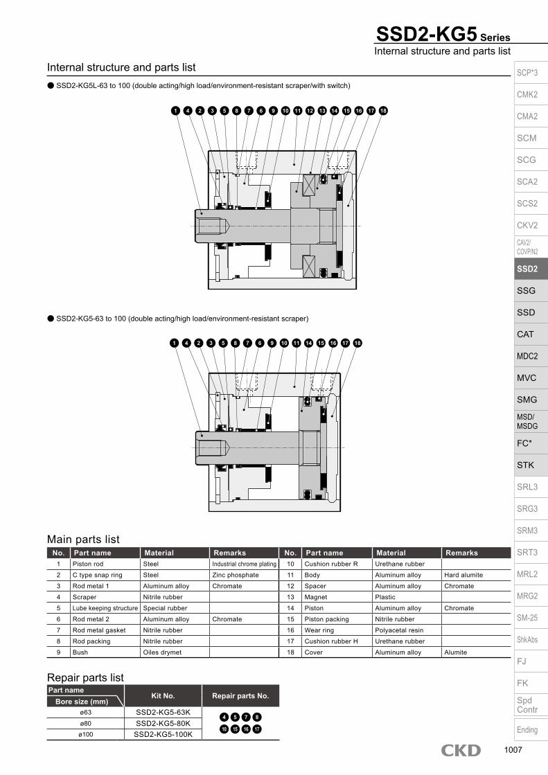
Internal structure and parts list SSD2-KG5L-63 to 100 (double acting/high load/environment-resistant scraper/with switch)
SSD2-KG5 SeriesInternal structure and parts list
SSD2-KG5-63 to 100 (double acting/high load/environment-resistant scraper)
Main parts listNo. Part name Material Remarks No. Part name Material Remarks
1 Piston rod Steel Industrial chrome plating 10 Cushion rubber R Urethane rubber
2 C type snap ring Steel Zinc phosphate 11 Body Aluminum alloy Hard alumite
3 Rod metal 1 Aluminum alloy Chromate 12 Spacer Aluminum alloy Chromate
4 Scraper Nitrile rubber 13 Magnet Plastic
5 Lube keeping structure Special rubber 14 Piston Aluminum alloy Chromate
6 Rod metal 2 Aluminum alloy Chromate 15 Piston packing Nitrile rubber
7 Rod metal gasket Nitrile rubber 16 Wear ring Polyacetal resin
8 Rod packing Nitrile rubber 17 Cushion rubber H Urethane rubber
9 Bush Oiles drymet 18 Cover Aluminum alloy Alumite
Part nameKit No. Repair parts No.
Bore size (mm)ø63 SSD2-KG5-63K
4 5 7 8
10 15 16 17ø80 SSD2-KG5-80K
ø100 SSD2-KG5-100K
Repair parts list
1 4 2 3 5 8 7 10 11 12 13 14 156 9 16 17 18
1 4 2 3 5 8 7 10 11 14 15 16 176 9 18
SCP*3
CMK2
CMA2
SCM
SCG
SCA2
SCS2
CKV2
CAV2/COVP/N2
SSD2
SSG
SSD
CAT
MDC2
MVC
SMG
MSD/MSDG
FC*
STK
SRL3
SRG3
SRM3
SRT3
MRL2
MRG2
SM‑25
ShkAbs
FJ
FK
SpdContr
Ending
1007

SSD2-KG5 Series
Dimensions (ø20, ø25) SSD2-KG5L-20, 25 (with switch/TOH/V, T5H/V, T2H/V, T3H/V) Rod end male thread
Code Without switch Common dimensions with switchBore size A *1 B *1 A *1 B *1 C D EE F FA *4 FB
ø20 39 34.5 49 44.5 18 5.5 M5 36 18.5(22) 12.5ø25 42.5 37.5 52.5 47.5 21 6 M5 40 20.5(24) 13.5
Switch dimensions Reed/proximity 1-color Proximity 2-colorBore size HD RD HD RD
ø20 6 18.5 4.5 18.5ø25 5.5 22 4 22
Switch dimensions
Proximity F2H/V, F3H/VF2YH/V, F3YH/V Proximity F2S/F3S
Bore size HD RD HD RDø20 10.5 23 9 23ø25 10 26.5 8.5 26.5
Codea’ c’ H kk’ M MM T wf
Bore sizeø20 14 12 13 M8 8 10 5 4.5ø25 17.5 15 17 M10×1.25 10 12 6 5
Rod end male thread
*1 : To calculate A+ stroke length or B+ stroke length when using custom stroke length, apply the next longer standard stroke length (instead of the custom stroke length) to the stroke length value. (Example) If the custom stroke length is 7 mm, apply the standard stroke length of 10 mm.
*2 : HD and RD dimensions for 5 mm stroke length differ from these dimensions according to the setting.
*3 : Refer to page 1044 for HD, RD and protruding dimensions of the 2-color display, off-delay, AC magnetic field proof, T1* and T8* switches.
*4 : Dimensions in ( ) of FA are for the radial lead wire.*5 : For dimensions of individual accessories, refer to
pages 1046 to 1049.
Code Common dimensions with switchBore size I J K KA KK M MM N WF
ø20 5.5 9 spot face depth 5.5 47 M6 depth 11 M5 depth 7 8 10 25.5 4.5ø25 5.5 9 spot face depth 5.5 51 M6 depth 11 M6 depth 12 10 12 28 5
SSD2-KG5-20, 25 (without switch)
a’c’
T
wf
øMM
kk’Width across flats M
Width across flats H
*4
8-JMounting hole
FA
øK
M
NF
FB N F
øMM
WF
KK
RD
C D
HD
2-EE
8-KAøI
A + stroke length
B + stroke length
F
8-JMounting hole
F N
M
N
øK
øMM
WF
KK
øI
C D
8-KA
2-EE
A + stroke lengthB + stroke length
SCP*3
CMK2
CMA2
SCM
SCG
SCA2
SCS2
CKV2
CAV2/COVP/N2
SSD2
SSG
SSD
CAT
MDC2
MVC
SMG
MSD/MSDG
FC*
STK
SRL3
SRG3
SRM3
SRT3
MRL2
MRG2
SM‑25
ShkAbs
FJ
FK
SpdContr
Ending
1008

SSD2-KG5 SeriesDimensions
Dimensions SSD2-KG5L-32 to 100 (with switch/TOH/V, T5H/V, T2H/V, T3H/V) Rod end male thread
Code Without switch Common dimensions with switchBore size A *1 B *1 A *1 B *1 C D EE F FA *3 FB G H
ø32 50(60) 43(53) 60 53 18 8 Rc1/8 45 23(26.5) 20.5 49.5 12.5ø40 56.5(66.5) 49.5(59.5) 66.5 59.5 22 8.5 Rc1/8 52 26.5(30) 27.5 57 15ø50 58.5(68.5) 50.5(60.5) 68.5 60.5 20.5 10.5 Rc1/4 64 32.5(36) 28.5 71 18ø63 64(74) 56(66) 74 66 23 11 Rc1/4 77 39(42.5) 28.5 84 23ø80 73.5(83.5) 63.5(73.5) 83.5 73.5 26 13 Rc3/8 98 49.5(53) 28.5 104 31
ø100 85(95) 73(83) 95 83 33 15 Rc3/8 117 59(62.5) 28.5 123.5 38
Switch dimensions Reed/proximity 1-color Proximity 2-color T8H/V switchBore size HD RD HD RD HD RD
ø32 8.5 24 7 22.5 - -ø40 9.5 29.5 8 28 3.5 23.5ø50 10 30 8.5 28.5 4 24ø63 17.5 28 16 26.5 11.5 22ø80 22 30.5 20.5 29 16 24.5
ø100 28 34.5 26.5 33 22 28.5
Codea’ c’ H kk’ M MM T wf
Bore sizeø32 23.5 20.5 22 M14x1.5 14 16 8 5ø40 23.5 20.5 22 M14x1.5 14 16 8 5ø50 28.5 26 27 M18x1.5 17 20 11 5ø63 28.5 26 27 M18x1.5 17 20 11 5ø80 35.5 32.5 32 M22x1.5 22 25 13 8
ø100 35.5 32.5 41 M26x1.5 27 30 16 8
Rod end male thread
*1 : To calculate A+ stroke length or B+ stroke length when using custom stroke length, apply the next longer standard stroke length (instead of the custom stroke length) to the stroke length value. (Example) If the custom stroke length is 7 mm, apply the standard stroke length of 10 mm.
*2 : HD and RD dimensions for 5 mm stroke length differ from these dimensions according to the setting.
*3 : Dimensions in ( ) of FA are for the radial lead wire.*4 : For dimensions of individual accessories, refer to
pages 1046 to 1049.*5 : Dimensions in ( ) of codes A and B are for stroke lengths of
more than 50 mm.
Code Common dimensions with switchBore size I J K KA KK M MM N O WF
ø32 5.5 9 spot face depth 5.5 60 M6 depth 11 M8 depth 13 14 16 34 4.5 7ø40 5.5 9 spot face depth 5.5 69 M6 depth 11 M8 depth 13 14 16 40 5 7ø50 6.9 11 spot face depth 6.5 86 M8 depth 13 M10 depth 15 17 20 50 7 8ø63 8.7 14 spot face depth 9 103 M10 depth 25 M10 depth 15 17 20 60 7 8ø80 10.5 17.5 spot face depth 11 132 M12 depth 28 M16 depth 21 22 25 77 6 10
ø100 10.5 17.5 spot face depth 11 156 M12 depth 28 M20 depth 27 27 30 94 6.5 12
SSD2-32 to 100 (without switch)
a’c’
T
wf
øMM
kk’Width across flats M
Width across flats H
*4
øK
G N
M
N
0F FB
FA
F
H8-J
Mounting hole
øMM
WF
KK
RD
C D
HD
2-EE
8-KAøI
A + stroke lengthB + stroke length
øK
øMM
WF
KK
C D 2-EE
8-KA øI
A + stroke lengthB + stroke length
G
M
N
0F N
F
H8-J
Mounting hole
SCP*3
CMK2
CMA2
SCM
SCG
SCA2
SCS2
CKV2
CAV2/COVP/N2
SSD2
SSG
SSD
CAT
MDC2
MVC
SMG
MSD/MSDG
FC*
STK
SRL3
SRG3
SRM3
SRT3
MRL2
MRG2
SM‑25
ShkAbs
FJ
FK
SpdContr
Ending
1009

Dimensions with mounting bracket Axial foot (LB) SSD2-KG5(L)-20 to 100 -LB
Clevis bracket (CB) SSD2-KG5(L)-20 to 100 -CB
· ø20/ø25
· ø20/ø25
· ø32 to ø100
· ø32 to ø100
SSD2-KG5 Series
Code Common dimensions Female thread Male threadBore size
(mm) AB AD AE AG AH AK AT AU G N TR TS M LF WF Without switch With switch a’ wf Without switch With switchA B LX A B LX A B LX A B LX
ø20 7 - - 42 24 15 3.2 9.2 M6×16 25.5 48 62 7.2 20.5 14.5 56.2 34.5 22.5 66.2 44.5 32.5 14 14.5 70.2 34.5 22.5 80.2 44.5 32.5ø25 7 - - 46 26 16.5 3.2 10.7 M6×16 28 52 66 7.2 22.5 15 59.7 37.5 22.5 69.7 47.5 32.5 17.5 15 77.2 37.5 22.5 87.2 47.5 32.5ø32 7 18.5 13 57 30 17 3.2 11.2 M6×16 34 57 71 7.2 25 17 67.2 43 27 77.2 53 37 23.5 15 88.7 43 27 98.7 53 37ø40 7 18 13 64 33 18.2 3.2 11.2 M6×16 40 64 78 7.2 25 17 73.7 49.5 33.5 83.7 59.5 43.5 23.5 15 95.2 49.5 33.5 105.2 59.5 43.5ø50 9 22 14 78 39 22.7 3.2 14.7 M8×20 50 79 95 8.2 29.5 18 76.7 50.5 27.5 86.7 60.5 37.5 28.5 15 102.2 50.5 27.5 112.2 60.5 37.5ø63 11 26 16 91.5 46 25.2 3.2 16.2 M10×25 60 95 113 9.2 31 18 83.2 56 30 93.2 66 40 28.5 15 108.7 56 30 118.7 66 40ø80 13 31.5 20.5 114 59 30.5 4.5 19.5 M12×40 77 118 140 11.5 35 20 95 63.5 33.5 105 73.5 43.5 35.5 18 128.5 63.5 33.5 138.5 73.5 43.5
ø100 13 35 24 136 71 35.5 6 23 M12×40 94 137 162 13 39 22 108 73 39 118 83 49 35.5 18 139.5 73 39 149.5 83 49
Code Common dimensions Female thread Male threadBore size
(mm) AC CA CB CC CD D E G H MR N UB WF Without switch With switch a’ wf Without switch With switchA B CJ A B CJ A B CJ A B CJ
ø20 - 20 8.2 12 8 5 36 M6×16 C4 - 25.5 16 4.5 66 34.5 57 76 44.5 67 14 4.5 80 34.5 57 90 44.5 67ø25 - 24 10.2 14 10 5 40 M6×16 C5 - 28 20 5 72.5 37.5 62.5 82.5 47.5 72.5 17.5 5 90 37.5 62.5 100 47.5 72.5ø32 4.5 - 18.2 14 10 5 45 M6×16 - 10 34 36 7 80 43 70 90 53 80 23.5 5 101.5 43 68 111.5 53 78ø40 5 - 18.2 14 10 6 52 M6×16 - 10 40 36 7 88.5 49.5 78.5 98.5 59.5 88.5 23.5 5 110 49.5 76.5 120 59.5 86.5ø50 6 - 22.2 20 14 7 64 M8×20 - 14 50 44 8 100.5 50.5 86.5 110.5 60.5 96.5 28.5 5 126 50.5 83.5 136 60.5 93.5ø63 7 - 22.2 20 14 8 77 M10×25 - 14 60 44 8 108 56 94 118 66 104 28.5 5 133.5 56 91 143.5 66 101ø80 9 - 28.2 27 18 10 98 M12×40 - 18 77 56 10 129.5 63.5 111.5 139.5 73.5 121.5 35.5 8 163 63.5 109.5 173 73.5 119.5
ø100 12 - 32.2 31 22 13 117 M12×40 - 22 94 64 12 152 73 130 162 83 140 35.5 8 183.5 73 126 193.5 83 136
N
AG N
TRTS
AT
AH
4-øAB
WFA + stroke length
B + stroke length M
AUAK
Low head hexagon socket bolt 8-G
LX + stroke length
NTRTS
4-øAB
AD
AE AT A
H
A + stroke lengthB + stroke lengtha’ wf
LFLF
A + stroke lengthRod end male thread
B + stroke lengtha’ wf
LX + stroke length
A + stroke lengthB + stroke length
Low head hexagon socket bolt 4-G
LF
WF
AUAK
M
Rod end male thread
AG
LF
NN
WF
A + stroke lengthB + stroke lengtha’ wf
A + stroke lengthRod end male thread
B + stroke lengtha’ wf
A + stroke lengthB + stroke lengthWF
Rod end male thread
A + stroke lengthB + stroke length
H
CJ + stroke lengthMounting bolt 4-C
N
E
E
CC
UBD
øCA
CD H10
CJ + stroke lengthCJ + stroke length
CJ + stroke length
CC
UBD
NE
E
CD H10
Mounting bolt 4-GAC
R MR
CB+ 0.2 0
CB+ 0.2 0
SCP*3
CMK2
CMA2
SCM
SCG
SCA2
SCS2
CKV2
CAV2/COVP/N2
SSD2
SSG
SSD
CAT
MDC2
MVC
SMG
MSD/MSDG
FC*
STK
SRL3
SRG3
SRM3
SRT3
MRL2
MRG2
SM‑25
ShkAbs
FJ
FK
SpdContr
Ending
1010
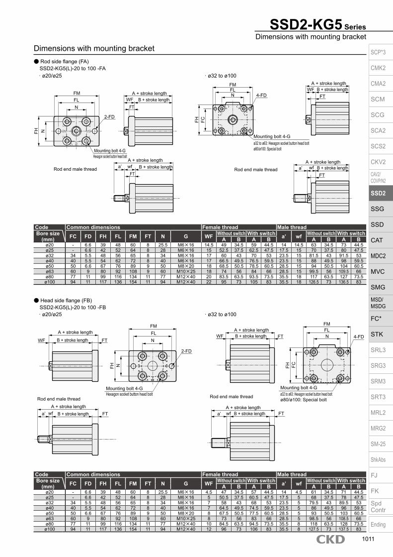
Dimensions with mounting bracket Rod side flange (FA) SSD2-KG5(L)-20 to 100 -FA
Head side flange (FB) SSD2-KG5(L)-20 to 100 -FB
· ø20/ø25
· ø20/ø25
· ø32 to ø100
· ø32 to ø100
SSD2-KG5 SeriesDimensions with mounting bracket
Code Common dimensions Female thread Male threadBore size
(mm) FC FD FH FL FM FT N G WF Without switch With switch a’ wf Without switch With switchA B A B A B A B
ø20 - 6.6 39 48 60 8 25.5 M6×16 14.5 49 34.5 59 44.5 14 14.5 63 34.5 73 44.5ø25 - 6.6 42 52 64 8 28 M6×16 15 52.5 37.5 62.5 47.5 17.5 15 70 37.5 80 47.5ø32 34 5.5 48 56 65 8 34 M6×16 17 60 43 70 53 23.5 15 81.5 43 91.5 53ø40 40 5.5 54 62 72 8 40 M6×16 17 66.5 49.5 76.5 59.5 23.5 15 88 49.5 98 59.5ø50 50 6.6 67 76 89 9 50 M8×20 18 68.5 50.5 78.5 60.5 28.5 15 94 50.5 104 60.5ø63 60 9 80 92 108 9 60 M10×25 18 74 56 84 66 28.5 15 99.5 56 109.5 66ø80 77 11 99 116 134 11 77 M12×40 20 83.5 63.5 93.5 73.5 35.5 18 117 63.5 127 73.5ø100 94 11 117 136 154 11 94 M12×40 22 95 73 105 83 35.5 18 126.5 73 136.5 83
Code Common dimensions Female thread Male threadBore size
(mm) FC FD FH FL FM FT N G WF Without switch With switch a’ wf Without switch With switchA B A B A B A B
ø20 - 6.6 39 48 60 8 25.5 M6×16 4.5 47 34.5 57 44.5 14 4.5 61 34.5 71 44.5ø25 - 6.6 42 52 64 8 28 M6×16 5 50.5 37.5 60.5 47.5 17.5 5 68 37.5 78 47.5ø32 34 5.5 48 56 65 8 34 M6×16 7 58 43 68 53 23.5 5 79.5 43 89.5 53ø40 40 5.5 54 62 72 8 40 M6×16 7 64.5 49.5 74.5 59.5 23.5 5 86 49.5 96 59.5ø50 50 6.6 67 76 89 9 50 M8×20 8 67.5 50.5 77.5 60.5 28.5 5 93 50.5 103 60.5ø63 60 9 80 92 108 9 60 M10×25 8 73 56 83 66 28.5 5 98.5 56 108.5 66ø80 77 11 99 116 134 11 77 M12×40 10 84.5 63.5 94.5 73.5 35.5 8 118 63.5 128 73.5ø100 94 11 117 136 154 11 94 M12×40 12 96 73 106 83 35.5 8 127.5 73 137.5 83
A + stroke lengthB + stroke length
FM
NFH
N
2-FD
Mounting bolt 4-GHexagon socket button head bolt
Rod end male thread
FT
A + stroke lengthB + stroke length
FTa’ wf
Rod end male thread
A + stroke lengthB + stroke length
A + stroke lengthB + stroke lengtha’ wfFT
FTWFFL
FH FC
FM
NFL
4-FD
Mounting bolt 4-Gø32 to ø63: Hexagon socket button head boltø80/ø100: Special bolt
WF
N
FM
FH
WF
Mounting bolt 4-GHexagon socket button head bolt
FH FC
A + stroke lengthB + stroke lengtha’ wf FT
A + stroke length
Rod end male thread
B + stroke lengtha’ wf
A + stroke lengthB + stroke lengthFL WF
FT
Rod end male thread
A + stroke length
B + stroke length FT N
2-FD
4-FDFLN
Mounting bolt 4-G
FM
FT
ø32 to ø63: Hexagon socket button head boltø80/ø100: Special bolt
SCP*3
CMK2
CMA2
SCM
SCG
SCA2
SCS2
CKV2
CAV2/COVP/N2
SSD2
SSG
SSD
CAT
MDC2
MVC
SMG
MSD/MSDG
FC*
STK
SRL3
SRG3
SRM3
SRT3
MRL2
MRG2
SM‑25
ShkAbs
FJ
FK
SpdContr
Ending
1011
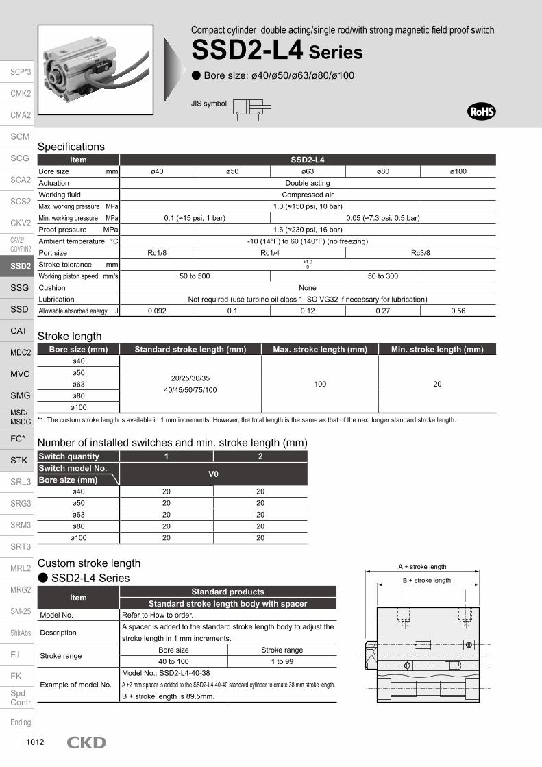
Compact cylinder double acting/single rod/with strong magnetic field proof switch
SSD2-L4 Series Bore size: ø40/ø50/ø63/ø80/ø100
JIS symbol
SpecificationsItem SSD2-L4
Bore size mm ø40 ø50 ø63 ø80 ø100Actuation Double actingWorking fluid Compressed airMax. working pressure MPa 1.0 (≈150 psi, 10 bar)Min. working pressure MPa 0.1 (≈15 psi, 1 bar) 0.05 (≈7.3 psi, 0.5 bar)Proof pressure MPa 1.6 (≈230 psi, 16 bar)Ambient temperature °C -10 (14°F) to 60 (140°F) (no freezing)Port size Rc1/8 Rc1/4 Rc3/8Stroke tolerance mm +1.0
0
Working piston speed mm/s 50 to 500 50 to 300Cushion NoneLubrication Not required (use turbine oil class 1 ISO VG32 if necessary for lubrication)Allowable absorbed energy J 0.092 0.1 0.12 0.27 0.56
Stroke length
*1: The custom stroke length is available in 1 mm increments. However, the total length is the same as that of the next longer standard stroke length.
Bore size (mm) Standard stroke length (mm) Max. stroke length (mm) Min. stroke length (mm)ø40
20/25/30/3540/45/50/75/100
100 20ø50ø63ø80ø100
Custom stroke length SSD2-L4 Series
ItemStandard products
Standard stroke length body with spacerModel No. Refer to How to order.
DescriptionA spacer is added to the standard stroke length body to adjust the stroke length in 1 mm increments.
Stroke rangeBore size Stroke range40 to 100 1 to 99
Example of model No.Model No.: SSD2-L4-40-38A +2 mm spacer is added to the SSD2-L4-40-40 standard cylinder to create 38 mm stroke length. B + stroke length is 89.5mm.
Switch quantity 1 2Switch model No.
V0Bore size (mm)
ø40 20 20ø50 20 20ø63 20 20ø80 20 20ø100 20 20
Number of installed switches and min. stroke length (mm)
A + stroke length
B + stroke length
SCP*3
CMK2
CMA2
SCM
SCG
SCA2
SCS2
CKV2
CAV2/COVP/N2
SSD2
SSG
SSD
CAT
MDC2
MVC
SMG
MSD/MSDG
FC*
STK
SRL3
SRG3
SRM3
SRT3
MRL2
MRG2
SM‑25
ShkAbs
FJ
FK
SpdContr
Ending
1012

SSD2-L4 SeriesSpecifications
Switch specificationsItem
Reed 2-wireV0
Applications For relay, programmable controllerLoad voltage 12/24 VDC 110 VACLoad current 5 to 50 mA 7 to 20 mAInternal voltage drop 3.0 V or less (with 40 mA load current)Indicator lamp LED (Lit when ON)Leakage current 0 mAWeight g 1 m:63 3 m:170 5 m:277
Bore size (mm)
Operating direction
Working pressure MPa0.05 0.1 0.15 0.2 0.3 0.4 0.5 0.6 0.7 0.8 0.9 1.0
ø40Push - 1.26×10² 1.88×10² 2.51×10² 3.77×10² 5.03×10² 6.28×10² 7.54×10² 8.80×10² 1.01×10³ 1.13×10³ 1.26×10³
Pull - 1.06×10² 1.58×10² 2.11×10² 3.17×10² 4.22×10² 5.28×10² 6.33×10² 7.39×10² 8.44×10² 9.50×10² 1.06×10³
ø50Push - 1.96×10² 2.95×10² 3.93×10² 5.89×10² 7.85×10² 9.82×10² 1.18×10³ 1.37×10³ 1.57×10³ 1.77×10³ 1.96×10³
Pull - 1.65×10² 2.47×10² 3.30×10² 4.95×10² 6.60×10² 8.25×10² 9.90×10² 1.15×10³ 1.32×10³ 1.48×10³ 1.65×10³
ø63Push 1.56×10² 3.12×10² 4.68×10² 6.23×10² 9.35×10² 1.25×10³ 1.56×10³ 1.87×10³ 2.18×10³ 2.49×10³ 2.81×10³ 3.12×10³
Pull 1.40×10² 2.80×10² 4.20×10² 5.61×10² 8.41×10² 1.12×10³ 1.40×10³ 1.68×10³ 1.96×10³ 2.24×10³ 2.52×10³ 2.80×10³
ø80Push 2.51×10² 5.03×10² 7.54×10² 1.01×10³ 1.51×10³ 2.01×10³ 2.51×10³ 3.02×10³ 3.52×10³ 4.02×10³ 4.52×10³ 5.03×10³
Pull 2.27×10² 4.54×10² 6.80×10² 9.07×10² 1.36×10³ 1.81×10³ 2.27×10³ 2.72×10³ 3.17×10³ 3.63×10³ 4.08×10³ 4.54×10³
ø100Push 3.93×10² 7.85×10² 1.18×10³ 1.57×10³ 2.36×10³ 3.14×10³ 3.93×10³ 4.71×10³ 5.50×10³ 6.28×10³ 7.07×10³ 7.85×10³
Pull 3.57×10² 7.15×10² 1.07×10³ 1.43×10³ 2.14×10³ 2.86×10³ 3.57×10³ 4.29×10³ 5.00×10³ 5.72×10³ 6.43×10³ 7.15×10³
Theoretical thrust table (Unit: N)
Stroke length (mm)20 25 30 35 40 45 50 75 100
Bore size (mm)ø40 493 520 546 573 599 626 652 785 917ø50 757 799 841 883 925 967 1009 1219 1429ø63 1089 1145 1200 1256 1311 1367 1422 1700 1977ø80 1822 1909 1996 2083 2170 2257 2344 2779 3214ø100 2665 2779 2892 3006 3119 3233 3346 3914 4481
Cylinder weight table (the weight of the switches is when there are 2 cylinder switches.) (Unit: g)
SCP*3
CMK2
CMA2
SCM
SCG
SCA2
SCS2
CKV2
CAV2/COVP/N2
SSD2
SSG
SSD
CAT
MDC2
MVC
SMG
MSD/MSDG
FC*
STK
SRL3
SRG3
SRM3
SRT3
MRL2
MRG2
SM‑25
ShkAbs
FJ
FK
SpdContr
Ending
1013

SSD2-L4 Series
Precautions for model No. selection*1 : The mounting bracket is included at shipment.*2 : The projection dimension of piston rod WF when LB or FA
is selected is different from that of the standard. Refer to the dimensions on page 1017. The number of the specified protruding dimension will be added at the end of the model No. printed on the metal plate on the body.
*3 : “I” and “Y” cannot be selected together.
[Example of model No.]SSD2-L4-50-40-V0-D-N-LB-IModel : Compact cylinder Double acting/single rod/with strong magnetic field proof switchA Bore size : ø50 mmB Stroke length : 40 mmC Switch model No. : Reed V0 switch, Lead wire length 1 mD Switch quantity : 2 pcs. includedE Option : Rod end male threadF Mounting bracket : Axial footG Accessory : Rod eye
How to order
Bore size (mm)ø40 ø50 ø63 ø80 ø100
Mounting bracketFoot (LB) SSD2-LB-40 SSD2-LB-50 SSD2-LB-63 SSD2-LB-80 SSD2-LB-100Flange (FA/FB) SSD2-FA-40 SSD2-FA-50 SSD2-FA-63 SSD2-FA-80 SSD2-FA-100Clevis bracket (CB) SSD2-CB-40 SSD2-CB-50 SSD2-CB-63 SSD2-CB-80 SSD2-CB-100*1: The foot mounting bracket is provided as 2 pcs./set.
How to order mounting bracket
Model No.
Accessory *3
G
Mounting bracket *1*2
F
B
Switch quantityD
C Switch model No.
Stroke length
IN40 D
Bore sizeA
50
Code Description
Bore size (mm)40 ø4050 ø5063 ø6380 ø80100 ø100
Stroke length (mm)
Refer to the stroke length table on the following page.
* Lead wire lengthBlank 1 m (standard)
3 3 m (option)5 5 m (option)
Switch quantityR 1 on rod sideH 1 on head sideD 2T 3
OptionBlank Rod end female thread
N Rod end male thread
Mounting bracketBlank Without mounting bracket
LB Axial footCB Clevis bracket (pin and snap ring included)FA Rod side flangeFB Head side flange
Accessory (available when rod end male thread “N” is selected)I Rod eyeY Rod clevis (pin and snap ring included)
Switch model No.Lead wire Contact Voltage Display
Lead wireStraight AC DC
V0* Reed 1-color display 2-wire
Stroke length (mm)Bore size Stroke length *1 Custom stroke length *2
ø40 to ø100 20 to 100 In 1 mm increments*1 : Refer to page 1012 for the number of installed switches and the min. stroke length.*2 : The total length when using a custom stroke length is the same as
that when using the next longer standard stroke length.
A
B
C
E
F
G
D
LBV0SSD2-L4
How to order switch
Switch model No. (Item C above)
SW V0
E Option
SCP*3
CMK2
CMA2
SCM
SCG
SCA2
SCS2
CKV2
CAV2/COVP/N2
SSD2
SSG
SSD
CAT
MDC2
MVC
SMG
MSD/MSDG
FC*
STK
SRL3
SRG3
SRM3
SRT3
MRL2
MRG2
SM‑25
ShkAbs
FJ
FK
SpdContr
Ending
1014

Internal structure and parts list SSD2-L4-40, 50
SSD2-L4-63 to 100
No. Part name Material Remarks No. Part name Material Remarks1 Piston rod Steel Industrial chrome plating 7 Spacer Aluminum alloy Chromate
2 C type snap ring Stainless steel 8 Magnet Plastic
3 Rod metal ø40, ø50: Special aluminumø63 to ø100: Aluminum alloy
ø40, ø50: Alumiteø63 to ø100: Chromate
9 Piston Aluminum alloy Chromate
10 Piston packing Nitrile rubber
4 Rod metal gasket Nitrile rubber 11 Cover Aluminum alloy Alumite
5 Body Aluminum alloy Hard alumite 12 Collar Aluminum alloy
6 Rod packing Nitrile rubber 13 Bush Oiles drymet ø63 to ø100 only
Bore size (mm) Kit No. Repair parts No.ø40 SSD2-40K
4 6 10
ø50 SSD2-50Kø63 SSD2-63Kø80 SSD2-80K
ø100 SSD2-100K
Repair parts list
SSD2-L4 SeriesInternal structure and parts list
1 2 3 6 5 8 9104 12 11
1 6 2 3 5 9104 7 1113
7
8 12
SCP*3
CMK2
CMA2
SCM
SCG
SCA2
SCS2
CKV2
CAV2/COVP/N2
SSD2
SSG
SSD
CAT
MDC2
MVC
SMG
MSD/MSDG
FC*
STK
SRL3
SRG3
SRM3
SRT3
MRL2
MRG2
SM‑25
ShkAbs
FJ
FK
SpdContr
Ending
1015

Dimensions SSD2-L4-40 to 100
CodeA B C D EE F FA FB G H I J
Bore size (mm)ø40 56.5 49.5 12 8.5 Rc1/8 52 36 31 57 15 5.5 Spot face ø9 depth 5.5
ø50 58.5 50.5 10.5 10.5 Rc1/4 64 42 32 71 18 6.9 Spot face ø11 depth 6.5
ø63 64 56 13 11 Rc1/4 77 48.5 32 84 23 8.7 Spot face ø14 depth 9
ø80 73.5 63.5 16 13 Rc3/8 98 59 32 104 31 10.5 Spot face ø17.5 depth 11
ø100 85 73 23 15 Rc3/8 117 68.5 32 123.5 38 10.5 Spot face ø17.5 depth 11
CodeK KA KK M MM N O WF HD RD
Bore size (mm)ø40 69 M6 depth 11 M8 depth 13 14 16 40 5 7 7.5 13
ø50 86 M8 depth 13 M10 depth 15 17 20 50 7 8 8.5 13
ø63 103 M10 depth 25 M10 depth 15 17 20 60 7 8 13.5 13.5
ø80 132 M12 depth 28 M16 depth 21 22 25 77 6 10 18.5 16
ø100 156 M12 depth 28 M20 depth 27 27 30 94 6.5 12 24 20
*1 : To calculate A+ stroke length or B+ stroke length when using custom stroke length, apply the next longer standard stroke length (instead of the custom stroke length) to the stroke length value.
(Example) If the custom stroke length is 23 mm, apply the standard stroke length 25 mm.*2 : For dimensions of individual accessories, refer to pages 1046 to 1049.
Rod end male thread
Codea’ c’ H kk’ M MM T wf
Bore size (mm)ø40 23.5 20.5 22 M14×1.5 14 16 8 5
ø50 28.5 26 27 M18×1.5 17 20 11 5
ø63 28.5 26 27 M18×1.5 17 20 11 5
ø80 35.5 32.5 32 M22×1.5 22 25 13 8
ø100 35.5 32.5 41 M26×1.5 27 30 16 8
Rod end male thread
SSD2-L4 Series
a’ wf
c’T
øMM
Width across flats MWidth across flats H
kk’
A + stroke length
B + stroke length
D
8-KA
øI
RD
øMM
KK2-EE
WF
CHD
27 5
FA
10F
N
H8-J
Mounting hole
G F N
øK M
FB8
O
SCP*3
CMK2
CMA2
SCM
SCG
SCA2
SCS2
CKV2
CAV2/COVP/N2
SSD2
SSG
SSD
CAT
MDC2
MVC
SMG
MSD/MSDG
FC*
STK
SRL3
SRG3
SRM3
SRT3
MRL2
MRG2
SM‑25
ShkAbs
FJ
FK
SpdContr
Ending
1016

Dimensions with mounting bracket Axial foot (LB) Clevis bracket (CB) SSD2-L4-40 to 100 -LB SSD2-L4-40 to 100 -CB
Rod side flange (FA) SSD2-L4-40 to 100 -FA
Head side flange (FB) SSD2-L4-40 to 100 -FB
SSD2-L4 SeriesDouble acting/single rod/with strong magnetic field proof switch
Code Common dimensionsBore size (mm) AB AD AE AG AH AK AT AU G N TR TS M LF
ø40 7 18 13 64 33 18.2 3.2 11.2 M6×16 40 64 78 7.2 25ø50 9 22 14 78 39 22.7 3.2 14.7 M8×20 50 79 95 8.2 29.5ø63 11 26 16 91.5 46 25.2 3.2 16.2 M10×25 60 95 113 9.2 31ø80 13 31.5 20.5 114 59 30.5 4.5 19.5 M12×40 77 118 140 11.5 35
ø100 13 35 24 136 71 35.5 6 23 M12×40 94 137 162 13 39Code Female thread Male threadBore size (mm) WF A B CJ a’ wf A B CJ
ø40 17 73.7 49.5 33.5 23.5 15 95.2 49.5 33.5ø50 18 76.7 50.5 27.5 28.5 15 102.7 50.5 27.5ø63 18 83.2 56 30 28.5 15 108.7 56 30ø80 20 95 63.5 33.5 35.5 18 128.5 63.5 33.5
ø100 22 108 73 39 35.5 18 139.5 73 39
Code Common dimensionsBore size (mm) AC CB CC CD D E G MR N UB
ø40 5 18.2 14 10 6 52 M6×16 10 40 36ø50 6 22.2 20 14 7 64 M8×20 14 50 44ø63 7 22.2 20 14 8 77 M10×25 14 60 44ø80 9 28.2 27 18 10 98 M12×40 18 77 56
ø100 12 32.2 31 22 13 117 M12×40 22 94 64Code Female thread Male threadBore size (mm) WF A B CJ a’ wf A B CJ
ø40 7 88.5 49.5 78.5 23.5 5 110 49.5 76.5ø50 8 100.5 50.5 86.5 28.5 5 126 50.5 83.5ø63 8 108 56 94 28.5 5 133.5 56 91ø80 10 129.5 63.5 111.5 35.5 8 163 63.5 109.5
ø100 12 152 73 130 35.5 8 183.5 73 126
Code Common dimensions Female thread Male threadBore size
(mm) FC FD FH FL FM FT N G WF A B a’ wf A B
ø40 40 5.5 54 62 72 8 40 M6×16 17 66.5 49.5 23.5 15 88 49.5ø50 50 6.6 67 76 89 9 50 M8×20 18 68.5 50.5 28.5 15 94 50.5ø63 60 9 80 92 108 9 60 M10×25 18 74 56 28.5 15 99.5 56ø80 77 11 99 116 134 11 77 M12×40 20 83.5 63.5 35.5 18 117 63.5
ø100 94 11 117 136 154 11 94 M12×40 22 95 73 35.5 18 126.5 73
Code Common dimensions Female thread Male threadBore size
(mm) FC FD FH FL FM FT N G WF A B a’ wf A B
ø40 40 5.5 54 62 72 8 40 M6×16 7 64.5 49.5 23.5 5 86 49.5ø50 50 6.6 67 76 89 9 50 M8×20 8 67.5 50.5 28.5 5 93 50.5ø63 60 9 80 92 108 9 60 M10×25 8 73 56 28.5 5 98.5 56ø80 77 11 99 116 134 11 77 M12×40 10 84.5 63.5 35.5 8 118 63.5ø100 94 11 117 136 154 11 94 M12×40 12 96 73 35.5 8 127.5 73
NTRTS
4-øAB
AD
AE AT A
H
LF
A + stroke lengthRod end male thread
B + stroke lengtha’ wf
LX + stroke length
A + stroke lengthB + stroke length
Low head hexagon socket bolt 4-G
LF
WF
AUAK
M
AG
N
A + stroke lengthRod end male thread
B + stroke lengtha’ wf
A + stroke lengthB + stroke lengthWF
CJ + stroke length
CJ + stroke length
CC
UBD
NE
E
CD H10
Mounting bolt 4-GAC
R MR
Rod end male thread
A + stroke lengthB + stroke length
A + stroke lengthB + stroke lengtha’ wfFT
FT
FH FC
FM
NFL
4-FD
Mounting bolt 4-Gø32 to ø63: Hexagon socket button head boltø80/ø100: Special bolt
WF
FH FC
A + stroke lengthRod end male thread B + stroke lengtha’ wf
A + stroke lengthB + stroke lengthWF
FT
4-FDFLN
Mounting bolt 4-G
FM
FT
ø32 to ø63: Hexagon socket button head boltø80/ø100: Special bolt
CB+ 0.2 0
SCP*3
CMK2
CMA2
SCM
SCG
SCA2
SCS2
CKV2
CAV2/COVP/N2
SSD2
SSG
SSD
CAT
MDC2
MVC
SMG
MSD/MSDG
FC*
STK
SRL3
SRG3
SRM3
SRT3
MRL2
MRG2
SM‑25
ShkAbs
FJ
FK
SpdContr
Ending
1017

Compact cylinder double acting/single rod with strong magnetic field proof switch/coil scraper
SSD2-G1L4 Series Bore size: ø40/ø50/ø63/ø80/ø100JIS symbol
SpecificationsItem SSD2-G1L4
Bore size mm ø40 ø50 ø63 ø80 ø100Actuation Double actingWorking fluid Compressed airMax. working pressure MPa 1.0 (≈150 psi, 10 bar)Min. working pressure MPa 0.15 (≈22 psi, 1.5 bar) 0.1 (≈15 psi, 1 bar)Proof pressure MPa 1.6 (≈230 psi, 16 bar)Ambient temperature °C -10 (14°F) to 60 (140°F) (no freezing)Port size Rc1/8 Rc1/4 Rc3/8Stroke tolerance mm +1.0
0
Working piston speed mm/s 50 to 500 50 to 300Cushion NoneLubrication Not required (use turbine oil class 1 ISO VG32 if necessary for lubrication)Allowable absorbed energy J 0.092 0.1 0.12 0.27 0.56
Stroke length
Custom stroke length SSD2-G1L4 Series
ItemStandard products
Standard stroke length body with spacerModel No. Refer to How to order.
DescriptionA spacer is added to the standard stroke length body to adjust the stroke length in 1 mm increments.
Stroke rangeBore size Stroke range40 to 100 1 to 99
Example of model No.Model No.: SSD2-G1L4-40-38A +2 mm spacer is added to the SSD2-G1L4-40-40 standard cylinder to create 38 mm stroke length. B + stroke length is 89.5mm.
Switch quantity 1 2 3Switch model No.
V0Bore size (mm)
ø40 20 20 35ø50 20 20 35ø63 20 20 35ø80 20 20 35ø100 20 20 35
Number of installed switches and min. stroke length (mm)
*1: The custom stroke length is available in 1 mm increments. However, the total length is the same as that of the next longer standard stroke length.
Bore size (mm) Standard stroke length (mm) Max. stroke length (mm) Min. stroke length (mm)ø40
20/25/30/35/ 40/45/50/75/100
100 20ø50ø63ø80ø100
A + stroke length
B + stroke length
SCP*3
CMK2
CMA2
SCM
SCG
SCA2
SCS2
CKV2
CAV2/COVP/N2
SSD2
SSG
SSD
CAT
MDC2
MVC
SMG
MSD/MSDG
FC*
STK
SRL3
SRG3
SRM3
SRT3
MRL2
MRG2
SM‑25
ShkAbs
FJ
FK
SpdContr
Ending
1018
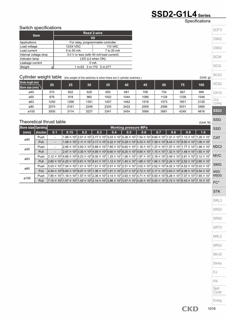
SSD2-G1L4 SeriesSpecifications
Stroke length (mm)20 25 30 35 40 45 50 75 100
Bore size (mm)ø40 575 602 628 655 681 708 734 867 999ø50 876 918 960 1002 1044 1086 1128 1338 1548ø63 1240 1296 1351 1407 1462 1518 1573 1851 2128ø80 2074 2161 2248 2335 2422 2509 2596 3031 3466
ø100 3000 3114 3227 3341 3454 3568 3681 4249 4816
Cylinder weight table (the weight of the switches is when there are 2 cylinder switches.)
Switch specificationsItem
Reed 2-wireV0
Applications For relay, programmable controllerLoad voltage 12/24 VDC 110 VACLoad current 5 to 50 mA 7 to 20 mAInternal voltage drop 3.0 V or less (with 40 mA load current)Indicator lamp LED (Lit when ON)Leakage current 0 mAWeight g 1 m:63 3 m:170 5 m:277
Bore size (mm)
Operating direction
Working pressure MPa0.1 0.15 0.2 0.3 0.4 0.5 0.6 0.7 0.8 0.9 1.0
ø40Push - 1.88×10² 2.51×10² 3.77×10² 5.03×10² 6.28×10² 7.54×10² 8.80×10² 1.01×10³ 1.13×10³ 1.26×10³
Pull - 1.58×10² 2.11×10² 3.17×10² 4.22×10² 5.28×10² 6.33×10² 7.39×10² 8.44×10² 9.50×10² 1.06×10³
ø50Push - 2.95×10² 3.93×10² 5.89×10² 7.85×10² 9.82×10² 1.18×10³ 1.37×10³ 1.57×10³ 1.77×10³ 1.96×10³
Pull - 2.47×10² 3.30×10² 4.95×10² 6.60×10² 8.25×10² 9.90×10² 1.15×10³ 1.32×10³ 1.48×10³ 1.65×10³
ø63Push 3.12×10² 4.68×10² 6.23×10² 9.35×10² 1.25×10³ 1.56×10³ 1.87×10³ 2.18×10³ 2.49×10³ 2.81×10³ 3.12×10³
Pull 2.80×10² 4.20×10² 5.61×10² 8.41×10² 1.12×10³ 1.40×10³ 1.68×10³ 1.96×10³ 2.24×10³ 2.52×10³ 2.80×10³
ø80Push 5.03×10² 7.54×10² 1.01×10³ 1.51×10³ 2.01×10³ 2.51×10³ 3.02×10³ 3.52×10³ 4.02×10³ 4.52×10³ 5.03×10³
Pull 4.54×10² 6.80×10² 9.07×10² 1.36×10³ 1.81×10³ 2.27×10³ 2.72×10³ 3.17×10³ 3.63×10³ 4.08×10³ 4.54×10³
ø100Push 7.85×10² 1.18×10³ 1.57×10³ 2.36×10³ 3.14×10³ 3.93×10³ 4.71×10³ 5.50×10³ 6.28×10³ 7.07×10³ 7.85×10³
Pull 7.15×10² 1.07×10³ 1.43×10³ 2.14×10³ 2.86×10³ 3.57×10³ 4.29×10³ 5.00×10³ 5.72×10³ 6.43×10³ 7.15×10³
Theoretical thrust table (Unit: N)
(Unit: g)
SCP*3
CMK2
CMA2
SCM
SCG
SCA2
SCS2
CKV2
CAV2/COVP/N2
SSD2
SSG
SSD
CAT
MDC2
MVC
SMG
MSD/MSDG
FC*
STK
SRL3
SRG3
SRM3
SRT3
MRL2
MRG2
SM‑25
ShkAbs
FJ
FK
SpdContr
Ending
1019

SSD2-G1L4 Series
Precautions for model No. selection*1 : The mounting bracket is included at shipment.*2 : “I” and “Y” cannot be selected together.
[Example of model No.]SSD2-G1L4-50-40-V0-D-N-LB-IModel: Compact cylinder
Double acting/with coil scraper/with strong magnetic field proof switch
A Bore size : ø50 mmB Stroke length : 40 mmC Switch model No. : Reed V0 switch, Lead wire length 1 mD Switch quantity : 2 pcs. includedE Option : Rod end male threadF Mounting bracket : Axial footG Accessory : Rod eye
Model No.
Accessory *2
G
How to order
Mounting bracket *1
F
OptionE
B
Switch quantityD
C Switch model No.
Stroke length
IN40 D
Bore size (mm)ø40 ø50 ø63 ø80 ø100
Mounting bracketFlange (FB) SSD2-FA-40 SSD2-FA-50 SSD2-FA-63 SSD2-FA-80 SSD2-FA-100Clevis bracket (CB) SSD2-CB-40 SSD2-CB-50 SSD2-CB-63 SSD2-CB-80 SSD2-CB-100*1: The foot mounting bracket is provided as 2 pcs./set.
How to order mounting bracket
How to order switch
Switch model No. (Item C above)
Bore size
A
50
Code Description
Bore size (mm)40 ø4050 ø5063 ø6380 ø80100 ø100
Stroke length (mm)
Refer to the stroke length table on the following page.
* Lead wire lengthBlank 1 m (standard)
3 3 m (option)5 5 m (option)
Switch quantityR 1 on rod sideH 1 on head sideD 2T 3
OptionBlank Rod end female thread
N Rod end male thread
Mounting bracketBlank Without mounting bracket
LB Axial foot (made-to-order product)CB Clevis bracket (pin and snap ring included)FA Rod side flange (made-to-order product)FB Head side flange
Accessory (available when rod end male thread “N” is selected)I Rod eyeY Rod clevis (pin and snap ring included)
Switch model No.Lead wire Contact Voltage Display
Lead wireStraight AC DC
V0* Reed 1-color display 2-wire
Stroke length (mm)Bore size Stroke length *1 Custom stroke length *2
ø40 to ø100 20 to 100 In 1 mm increments
*1 : Refer to page 1018 for the number of installed switches and the min. stroke length.*2 : The total length is the same as that of the next longer standard stroke length.
A
B
C
E
F
G
D
SSD2-G1L4 V0 LB
SW V0
SCP*3
CMK2
CMA2
SCM
SCG
SCA2
SCS2
CKV2
CAV2/COVP/N2
SSD2
SSG
SSD
CAT
MDC2
MVC
SMG
MSD/MSDG
FC*
STK
SRL3
SRG3
SRM3
SRT3
MRL2
MRG2
SM‑25
ShkAbs
FJ
FK
SpdContr
Ending
1020

Internal structure and parts list SSD2-G1L4-40, 50
SSD2-G1L4-63 to 100
No. Part name Material Remarks No. Part name Material Remarks1 Piston rod Steel Industrial chrome plating 8 Piston packing Nitrile rubber
2 Coil scraper Phosphor bronze 9 Piston Aluminum alloy Chromate
3 C type snap ring for hole Steel Zinc phosphate 10 Cover Aluminum alloy Chromate
4 Rod metal gasket Nitrile rubber 11 Bush Oiles drymet ø63 to ø100
5 Rod metal Aluminum alloy Chromate 12 Spacer Aluminum alloy
6 Rod packing Nitrile rubber 13 Magnet Plastic
7 Body Aluminum alloy Hard alumite
Part nameKit No. Repair parts No.
Bore size (mm)ø40 SSD2-G1-40K
2 4 6 8
ø50 SSD2-G1-50Kø63 SSD2-G1-63Kø80 SSD2-G1-80K
ø100 SSD2-G1-100K
Repair parts list
SSD2-G1L4 SeriesDouble acting/single rod with strong magnetic field proof switch/coil scraper
1 12
1 12 811 7 10
2 6 3 5 4 7 13 89 10
2 6 3 5 4 13 9
SCP*3
CMK2
CMA2
SCM
SCG
SCA2
SCS2
CKV2
CAV2/COVP/N2
SSD2
SSG
SSD
CAT
MDC2
MVC
SMG
MSD/MSDG
FC*
STK
SRL3
SRG3
SRM3
SRT3
MRL2
MRG2
SM‑25
ShkAbs
FJ
FK
SpdContr
Ending
1021

Dimensions SSD2-G1L4-40 to 100
CodeA B C D EE F FA FB G H I J
Bore size (mm)ø40 61.5 49.5 12 8.5 Rc1/8 52 36 31 57 15 5.5 9 spot face depth 5.5
ø50 63.5 50.5 10.5 10.5 Rc1/4 64 42 32 71 18 6.9 11 spot face depth 6.5
ø63 69 56 13 11 Rc1/4 77 48.5 32 84 23 8.7 14 spot face depth 9
ø80 78.5 63.5 16 13 Rc3/8 98 59 32 104 31 10.5 17.5 spot face depth 11
ø100 90 73 23 15 Rc3/8 117 68.5 32 123.5 38 10.5 17.5 spot face depth 11
CodeK KA KK M MM N O U WF HD RD
Bore size (mm)ø40 69 M6 depth 11 M8 depth 13 14 16 40 5 28 h9 12 7.5 13
ø50 86 M8 depth 13 M10 depth 15 17 20 50 7 35 h9 13 8.5 13
ø63 103 M10 depth 25 M10 depth 15 17 20 60 7 35 h9 13 13.5 13.5
ø80 132 M12 depth 28 M16 depth 21 22 25 77 6 43 h9 15 18.5 16
ø100 156 M12 depth 28 M20 depth 27 27 30 94 6.5 59 h9 17 24 20
*1 : The A + stroke length and B + stroke length when using a custom stroke length are the same as those when using the next longer standard stroke length.
*2 : For dimensions of individual accessories, refer to pages 1046 to 1049.
Rod end male thread
Codea’ c’ H kk’ M MM T wf
Bore size (mm)ø40 23.5 20.5 22 M14×1.5 14 16 8 10
ø50 28.5 26 27 M18×1.5 17 20 11 10
ø63 28.5 26 27 M18×1.5 17 20 11 10
ø80 35.5 32.5 32 M22×1.5 22 25 13 13
ø100 35.5 32.5 41 M26×1.5 27 30 16 13
Rod end male thread
SSD2-G1L4 Series
A + stroke length
B + stroke length
D
8-KA
øI
RD
øMM
2-EE
WF
CHD
KK
FA
10F
N
H8-J
Mounting hole
G FO
N
øKM
FB øU
5
a’
c’
T
wf
øMM
kk’ Width across flats M
Width across flats H
SCP*3
CMK2
CMA2
SCM
SCG
SCA2
SCS2
CKV2
CAV2/COVP/N2
SSD2
SSG
SSD
CAT
MDC2
MVC
SMG
MSD/MSDG
FC*
STK
SRL3
SRG3
SRM3
SRT3
MRL2
MRG2
SM‑25
ShkAbs
FJ
FK
SpdContr
Ending
1022
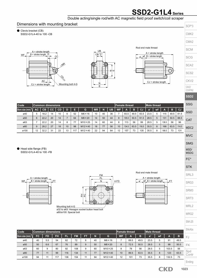
Dimensions with mounting bracket Clevis bracket (CB)
SSD2-G1L4-40 to 100 -CB
Head side flange (FB) SSD2-G1L4-40 to 100 -FB
SSD2-G1L4 SeriesDouble acting/single rod/with AC magnetic field proof switch/coil scraper
Code Common dimensions Female thread Male threadBore size (mm) AC CB CC CD D E G MR N UB WF A B CJ a’ wf A B CJ
ø40 5 18.2 14 10 6 52 M6×16 10 40 36 7 93.5 49.5 83.5 23.5 5 115 49.5 81.5
ø50 6 22.2 20 14 7 64 M8×20 14 50 44 8 105.5 50.5 91.5 28.5 5 131 50.5 88.5
ø63 7 22.2 20 14 8 77 M10×25 14 60 44 8 113 56 99 28.5 5 138.5 56 96
ø80 9 28.2 27 18 10 98 M12×40 18 77 56 10 134.5 63.5 116.5 35.5 8 168 63.5 114.5
ø100 12 32.2 31 22 13 117 M12×40 22 94 64 12 157 73 135 35.5 8 188.5 73 131
Code Common dimensions Female thread Male threadBore size (mm) FC FD FH FL FM FT N G WF A B a’ wf A B
ø40 40 5.5 54 62 72 8 40 M6×16 7 69.5 49.5 23.5 5 91 49.5
ø50 50 6.6 67 76 89 9 50 M8×20 8 72.5 50.5 28.5 5 98 50.5
ø63 60 9 80 92 108 9 60 M10×25 8 78 56 28.5 5 103.5 56
ø80 77 11 99 116 134 11 77 M12×40 10 89.5 63.5 35.5 8 123 63.5
ø100 94 11 117 136 154 11 94 M12×40 12 101 73 35.5 8 132.5 73
N
A + stroke length
Rod end male thread
B + stroke lengtha’ wf
A + stroke lengthB + stroke lengthWF
CJ + stroke lengthCJ + stroke length
CC
UBD
NE
E
CD H10
Mounting bolt 4-GAC
R MR
FH FC
A + stroke lengthB + stroke lengtha’ wf
A + stroke lengthB + stroke lengthWF FT4-FD
FLN
Mounting bolt 4-G
FM
FT
ø32 to ø63: Hexagon socket button head boltø80/ø100: Special bolt
Rod end male thread
CB + 0.2 0
SCP*3
CMK2
CMA2
SCM
SCG
SCA2
SCS2
CKV2
CAV2/COVP/N2
SSD2
SSG
SSD
CAT
MDC2
MVC
SMG
MSD/MSDG
FC*
STK
SRL3
SRG3
SRM3
SRT3
MRL2
MRG2
SM‑25
ShkAbs
FJ
FK
SpdContr
Ending
1023

Compact cylinder double acting/high load/with strong magnetic field proof switch
SSD2-KL4 Series Bore size: ø40/ø50/ø63/ø80/ø100JIS symbol
SpecificationsItem SSD2-KL4
Bore size mm ø40 ø50 ø63 ø80 ø100Actuation Double actingWorking fluid Compressed airMax. working pressure MPa 1.0 (≈150 psi, 10 bar)Min. working pressure MPa 0.1 (≈15 psi, 1 bar) 0.05 (≈7.3 psi, 0.5 bar)Proof pressure MPa 1.6 (≈230 psi, 16 bar)Ambient temperature °C -10 (14°F) to 60 (140°F) (no freezing)Port size Rc1/8 Rc1/4 Rc3/8Stroke tolerance mm +2.0
0
Working piston speed mm/s 50 to 500 50 to 300Cushion Rubber cushionLubrication Not required (use turbine oil class 1 ISO VG32 if necessary for lubrication)Allowable absorbed energy J 0.63 0.98 1.56 2.51 3.92
Stroke length
*1: The custom stroke length is available in 1 mm increments. However, the total length is the same as that of the next longer standard stroke length.
Bore size (mm) Standard stroke length (mm) Max. stroke length (mm) Min. stroke length (mm)ø40
20/25/30/35/4045/50/75/100
100 20ø50ø63ø80ø100
Custom stroke length SSD2-KL4 Series
ItemStandard products
Standard stroke length body with spacerModel No. Refer to How to order.
DescriptionA spacer is added to the standard stroke length body to adjust the stroke length in 1 mm increments.
Stroke rangeBore size Stroke range40 to 100 1 to 99
Example of model No.Model No.: SSD2-KL4-40-38A +2 mm spacer is added to the SSD2-KL4-40-40 standard cylinder to create 38 mm stroke length. B + stroke length is 99.5mm.
Switch quantity 1 2 3Switch model No.
V0Bore size (mm)
ø40 20 20 35ø50 20 20 35ø63 20 20 35ø80 20 20 35ø100 20 20 35
Number of installed switches and min. stroke length (mm)
A + stroke length
B + stroke length
SCP*3
CMK2
CMA2
SCM
SCG
SCA2
SCS2
CKV2
CAV2/COVP/N2
SSD2
SSG
SSD
CAT
MDC2
MVC
SMG
MSD/MSDG
FC*
STK
SRL3
SRG3
SRM3
SRT3
MRL2
MRG2
SM‑25
ShkAbs
FJ
FK
SpdContr
Ending
1024

SSD2-KL4 SeriesSpecifications
Switch specificationsItem
Reed 2-wireV0
Applications For relay, programmable controllerLoad voltage 12/24 VDC 110 VACLoad current 5 to 50 mA 7 to 20 mAInternal voltage drop 3.0 V or less (with 40 mA load current)Indicator lamp LED (Lit when ON)Leakage current 0 mAWeight g 1 m:63 3 m:170 5 m:277
Theoretical thrust tableBore size
(mm)Operating direction
Working pressure MPa0.05 0.1 0.15 0.2 0.3 0.4 0.5 0.6 0.7 0.8 0.9 1.0
ø40Push - 1.26×10² 1.88×10² 2.51×10² 3.77×10² 5.03×10² 6.28×10² 7.54×10² 8.80×10² 1.01×10³ 1.13×10³ 1.26×10³
Pull - 1.06×10² 1.58×10² 2.11×10² 3.17×10² 4.22×10² 5.28×10² 6.33×10² 7.39×10² 8.44×10² 9.50×10² 1.06×10³
ø50Push - 1.96×10² 2.95×10² 3.93×10² 5.89×10² 7.85×10² 9.82×10² 1.18×10³ 1.37×10³ 1.57×10³ 1.77×10³ 1.96×10³
Pull - 1.65×10² 2.47×10² 3.30×10² 4.95×10² 6.60×10² 8.25×10² 9.90×10² 1.15×10³ 1.32×10³ 1.48×10³ 1.65×10³
ø63Push 1.56×10² 3.12×10² 4.68×10² 6.23×10² 9.35×10² 1.25×10³ 1.56×10³ 1.87×10³ 2.18×10³ 2.49×10³ 2.81×10³ 3.12×10³
Pull 1.40×10² 2.80×10² 4.20×10² 5.61×10² 8.41×10² 1.12×10³ 1.40×10³ 1.68×10³ 1.96×10³ 2.24×10³ 2.52×10³ 2.80×10³
ø80Push 2.51×10² 5.03×10² 7.54×10² 1.01×10³ 1.51×10³ 2.01×10³ 2.51×10³ 3.02×10³ 3.52×10³ 4.02×10³ 4.52×10³ 5.03×10³
Pull 2.27×10² 4.54×10² 6.80×10² 9.07×10² 1.36×10³ 1.81×10³ 2.27×10³ 2.72×10³ 3.17×10³ 3.63×10³ 4.08×10³ 4.54×10³
ø100Push 3.93×10² 7.85×10² 1.18×10³ 1.57×10³ 2.36×10³ 3.14×10³ 3.93×10³ 4.71×10³ 5.50×10³ 6.28×10³ 7.07×10³ 7.85×10³
Pull 3.57×10² 7.15×10² 1.07×10³ 1.43×10³ 2.14×10³ 2.86×10³ 3.57×10³ 4.29×10³ 5.00×10³ 5.72×10³ 6.43×10³ 7.15×10³
(Unit: N)
Stroke length (mm)20 25 30 35 40 45 50 75 100
Bore size (mm)ø40 546 573 599 626 652 679 705 838 970ø50 841 883 925 967 1009 1051 1093 1303 1513ø63 1199 1254 1309 1364 1419 1474 1529 1804 2079ø80 1995 2082 2169 2256 2343 2430 2517 2952 3387ø100 2893 3007 3120 3234 3347 3461 3574 4142 4709
Cylinder weight table (the weight of the switches is when there are 2 cylinder switches.) (Unit: g)
SCP*3
CMK2
CMA2
SCM
SCG
SCA2
SCS2
CKV2
CAV2/COVP/N2
SSD2
SSG
SSD
CAT
MDC2
MVC
SMG
MSD/MSDG
FC*
STK
SRL3
SRG3
SRM3
SRT3
MRL2
MRG2
SM‑25
ShkAbs
FJ
FK
SpdContr
Ending
1025

Precautions for model No. selection*1 : The mounting bracket is included at shipment.*2 : The projection dimension of piston rod WF when LB or FA is
selected is different from that of the standard. Refer to the dimensions on page 1029. The number of the specified protruding dimension will be added at the end of the model No. printed on the metal plate on the body.
*3 : “I” and “Y” cannot be selected together.
[Example of model No.]SSD2-KL4-50-40-V0-D-N-LB-IModel: Compact cylinder
Double acting/single high load/with strong magnetic field proof switch
A Bore size : ø50 mmB Stroke length : 40 mmC Switch model No. : Reed V0 switch, Lead wire length 1 mD Switch quantity : 2 pcs. includedE Option : Rod end male threadF Mounting bracket : Axial footG Accessory : Rod eye
Model No.
Accessory *3
G
How to order
Mounting bracket *1*2
F
OptionE
B
Switch quantityD
C Switch model No.
Stroke length
IN40 D
Bore size
A
50
Code Description
Bore size (mm)40 ø4050 ø5063 ø6380 ø80100 ø100
Stroke length (mm)
* Lead wire lengthBlank 1 m (standard)
3 3 m (option)5 5 m (option)
Switch quantityR 1 on rod sideH 1 on head sideD 2T 3
OptionBlank Rod end female thread
N Rod end male thread
Mounting bracketBlank Without mounting bracket
LB Axial footCB Clevis bracket (pin and snap ring included)FA Rod side flangeFB Head side flange
Accessory (available when rod end male thread “N” is selected)I Rod eyeY Rod clevis (pin and snap ring included)
Switch model No.Lead wire Contact Voltage Display
Lead wireStraight AC DC
V0* Reed 1-color display 2-wire
A
B
C
E
F
G
D
SSD2-KL4 Series
Bore size (mm)ø40 ø50 ø63 ø80 ø100
Mounting bracketFoot (LB) SSD2-LB-40 SSD2-LB-50 SSD2-LB-63 SSD2-LB-80 SSD2-LB-100Flange (FA/FB) SSD2-FA-40 SSD2-FA-50 SSD2-FA-63 SSD2-FA-80 SSD2-FA-100Clevis bracket (CB) SSD2-CB-40 SSD2-CB-50 SSD2-CB-63 SSD2-CB-80 SSD2-CB-100
How to order switch
Switch model No. (Item C above)
*1: The foot mounting bracket is provided as 2 pcs./set.
How to order mounting bracket
SSD2-KL4 V0 LB
V0SW
Bore size Stroke length *1 Custom stroke length *2ø40 to ø100 20 to 100 In 1 mm increments
*1 : Refer to page 1024 for the number of installed switches and the min. stroke length.
*2 : The total length is the same as that of the next longer standard stroke length.
SCP*3
CMK2
CMA2
SCM
SCG
SCA2
SCS2
CKV2
CAV2/COVP/N2
SSD2
SSG
SSD
CAT
MDC2
MVC
SMG
MSD/MSDG
FC*
STK
SRL3
SRG3
SRM3
SRT3
MRL2
MRG2
SM‑25
ShkAbs
FJ
FK
SpdContr
Ending
1026

Internal structure and parts list SSD2-KL4-40, 50
SSD2-KL4-63 to 100
No. Part name Material Remarks No. Part name Material Remarks1 Piston rod Steel Industrial chrome plating 8 Magnet Plastic
2 C type snap ring Steel Zinc phosphate 9 Piston Aluminum alloy
3 Rod metal ø40, ø50: Special aluminumø63 to ø100: Aluminum alloy
ø40, ø50: Alumiteø63 to ø100: Chromate
10 Piston packing Nitrile rubber
11 Cover Aluminum alloy Alumite
4 Rod metal gasket Nitrile rubber 12 Bush Oiles drymet
5 Body Aluminum alloy Hard alumite 13 Cushion rubber (R) Urethane rubber
6 Rod packing Nitrile rubber 14 Cushion rubber (H) Urethane rubber
7 Spacer ø40, ø50: Special resinø63 to ø100: Aluminum alloy ø63 to ø100: Chromate
15 Wear ring Polyacetal resin
Bore size (mm) Kit No. Repair parts No.ø40 SSD2-K-40K
4 6 10
13 14 15
ø50 SSD2-K-50Kø63 SSD2-K-63Kø80 SSD2-K-80K
ø100 SSD2-K-100K
Repair parts list
SSD2-KL4 SeriesDouble acting/high load/with strong magnetic field proof switch
1 2 6 3 4 12 13 5 7 8 9 10 15 14 11
1 6 2 3412 13 5 7 8 9 10 15 14 11
SCP*3
CMK2
CMA2
SCM
SCG
SCA2
SCS2
CKV2
CAV2/COVP/N2
SSD2
SSG
SSD
CAT
MDC2
MVC
SMG
MSD/MSDG
FC*
STK
SRL3
SRG3
SRM3
SRT3
MRL2
MRG2
SM‑25
ShkAbs
FJ
FK
SpdContr
Ending
1027

Dimensions SSD2-KL4-40 to 100
CodeA B C D EE F FA FB G H I J
Bore size (mm)ø40 66.5 59.5 12 8.5 Rc1/8 52 36 31 57 15 5.5 Spot face ø9 depth 5.5
ø50 68.5 60.5 10.5 10.5 Rc1/4 64 42 32 71 18 6.9 Spot face ø11 depth 6.5
ø63 74 66 13 11 Rc1/4 77 48.5 32 84 23 8.7 Spot face ø14 depth 9
ø80 83.5 73.5 16 13 Rc3/8 98 59 32 104 31 10.5 Spot face ø17.5 depth 11
ø100 95 83 23 15 Rc3/8 117 68.5 32 123.5 38 10.5 Spot face ø17.5 depth 11
CodeK KA KK M MM N O WF HD RD
Bore size (mm)ø40 69 M6 depth 11 M8 depth 13 14 16 40 5 7 12.5 18
ø50 86 M8 depth 13 M10 depth 15 17 20 50 7 8 13.5 18
ø63 103 M10 depth 25 M10 depth 15 17 20 60 7 8 18.5 18.5
ø80 132 M12 depth 28 M16 depth 21 22 25 77 6 10 23.5 21
ø100 156 M12 depth 28 M20 depth 27 27 30 94 6.5 12 29 25
*1 : The A + stroke length and B + stroke length when using a custom stroke length are the same as those when using the next longer standard stroke length.
*2 : For dimensions of individual accessories, refer to pages 1046 to 1049.
Rod end male thread
Codea’ c’ H kk’ M MM T wf
Bore size (mm)ø40 23.5 20.5 22 M14×1.5 14 16 8 5
ø50 28.5 26 27 M18×1.5 17 20 11 5
ø63 28.5 26 27 M18×1.5 17 20 11 5
ø80 35.5 32.5 32 M22×1.5 22 25 13 8
ø100 35.5 32.5 41 M26×1.5 27 30 16 8
Rod end male thread
SSD2-KL4 Series
a’ wf
c’T
øMM
Width across flats MWidth across flats H
kk’
A + stroke length
B + stroke length
D
8-KA
øI
RD
øMM
2-EE
WF
CHD
27 5
KK
FA10F
N
H8-JMounting hole
G
OF N
M
FB
øK
SCP*3
CMK2
CMA2
SCM
SCG
SCA2
SCS2
CKV2
CAV2/COVP/N2
SSD2
SSG
SSD
CAT
MDC2
MVC
SMG
MSD/MSDG
FC*
STK
SRL3
SRG3
SRM3
SRT3
MRL2
MRG2
SM‑25
ShkAbs
FJ
FK
SpdContr
Ending
1028

SSD2-KL4 SeriesDouble acting/high load/with strong magnetic field proof switch
Dimensions with mounting bracket Axial foot (LB) Clevis bracket (CB)
SSD2-KL4-40 to 100 -LB SSD2-KL4-40 to 100 -CB
Rod side flange (FA) SSD2-KL4-40 to 100 -FA
Head side flange (FB) SSD2-KL4-40 to 100 -FB
Code Common dimensionsBore size (mm) AB AD AE AG AH AK AT AU G N TR TS M LF
ø40 7 18 13 64 33 18.2 3.2 11.2 M6×16 40 64 78 7.2 25ø50 9 22 14 78 39 22.7 3.2 14.7 M8×20 50 79 95 8.2 29.5ø63 11 26 16 91.5 46 25.2 3.2 16.2 M10×25 60 95 113 9.2 31ø80 13 31.5 20.5 114 59 30.5 4.5 19.5 M12×40 77 118 140 11.5 35
ø100 13 35 24 136 71 35.5 6 23 M12×40 94 137 162 13 39Code Female thread Male threadBore size (mm) WF A B LX a’ wf A B LX
ø40 17 83.7 59.5 43.5 23.5 15 105.2 59.5 43.5ø50 18 86.7 60.5 37.5 28.5 15 112.2 60.5 37.5ø63 18 93.2 66 40 28.5 15 118.7 66 40ø80 20 105 73.5 43.5 35.5 18 138.5 73.5 43.5ø100 22 118 83 49 35.5 18 149.5 83 49
Code Common dimensionsBore size (mm) AC CB CC CD D E G MR N UB
ø40 5 18.2 14 10 6 52 M6×16 10 40 36ø50 6 22.2 20 14 7 64 M8×20 14 50 44ø63 7 22.2 20 14 8 77 M10×25 14 60 44ø80 9 28.2 27 18 10 98 M12×40 18 77 56
ø100 12 32.2 31 22 13 117 M12×40 22 94 64Code Female thread Male threadBore size (mm) WF A B CJ a’ wf A B CJ
ø40 7 98.5 59.5 88.5 23.5 5 120 59.5 86.5ø50 8 110.5 60.5 96.5 28.5 5 136 60.5 93.5ø63 8 118 66 104 28.5 5 143.5 66 101ø80 10 139.5 73.5 121.5 35.5 8 173 73.5 119.5
ø100 12 162 83 140 35.5 8 193.5 83 136
Code Common dimensions Female thread Male threadBore size
(mm) FC FD FH FL FM FT N G WF A B a’ wf A B
ø40 40 5.5 54 62 72 8 40 M6×16 17 76.5 59.5 23.5 15 98 59.5ø50 50 6.6 67 76 89 9 50 M8×20 18 78.5 60.5 28.5 15 104 60.5ø63 60 9 80 92 108 9 60 M10×25 18 84 66 28.5 15 109.5 66ø80 77 11 99 116 134 11 77 M12×40 20 93.5 73.5 35.5 18 127 73.5
ø100 94 11 117 136 154 11 94 M12×40 22 105 83 35.5 18 136.5 83
Code Common dimensions Female thread Male threadBore size
(mm) FC FD FH FL FM FT N G WF A B a’ wf A B
ø40 40 5.5 54 62 72 8 40 M6×16 7 74.5 59.5 23.5 5 96 59.5ø50 50 6.6 67 76 89 9 50 M8×20 8 77.5 60.5 28.5 5 103 60.5ø63 60 9 80 92 108 9 60 M10×25 8 83 66 28.5 5 108.5 66ø80 77 11 99 116 134 11 77 M12×40 10 94.5 73.5 35.5 8 128 73.5ø100 94 11 117 136 154 11 94 M12×40 12 106 83 35.5 8 137.5 83
NTRTS
4-øAB
AD
AE AT A
H
LF
A + stroke lengthRod end male thread
B + stroke lengtha’ wf
LX + stroke length
A + stroke lengthB + stroke length
Low head hexagon socket bolt 4-G
LF
WF
AUAK
M
AG
N
A + stroke lengthRod end male thread
B + stroke lengtha’ wf
A + stroke lengthB + stroke lengthWF
CJ + stroke length
CJ + stroke length
CC
UBD
NE
E
CD H10
Mounting bolt 4-GAC
R MR
Rod end male thread
A + stroke lengthB + stroke length
A + stroke lengthB + stroke lengtha’ wfFT
FT
FH FC
FM
NFL
4-FD
Mounting bolt 4-Gø32 to ø63: Hexagon socket button head boltø80/ø100: Special bolt
WF
FH FC
A + stroke lengthB + stroke lengtha’ wf
A + stroke lengthB + stroke lengthWF
FT
4-FDFLN
Mounting bolt 4-G
FM
FT
ø32 to ø63: Hexagon socket button head boltø80/ø100: Special bolt
Rod end male thread
CB + 0.2 0
SCP*3
CMK2
CMA2
SCM
SCG
SCA2
SCS2
CKV2
CAV2/COVP/N2
SSD2
SSG
SSD
CAT
MDC2
MVC
SMG
MSD/MSDG
FC*
STK
SRL3
SRG3
SRM3
SRT3
MRL2
MRG2
SM‑25
ShkAbs
FJ
FK
SpdContr
Ending
1029

Compact cylinder double acting/high load/with strong magnetic field proof switch/with coil scraper
SSD2-KG1L4 Series Bore size: ø40/ø50/ø63/ø80/ø100JIS symbol
SpecificationsItem SSD2-KG1L4
Bore size mm ø40 ø50 ø63 ø80 ø100Actuation Double actingWorking fluid Compressed airMax. working pressure MPa 1.0 (≈150 psi, 10 bar)Min. working pressure MPa 0.15 (≈22 psi, 1.5 bar) 0.1 (≈15 psi, 1 bar)Proof pressure MPa 1.6 (≈230 psi, 16 bar)Ambient temperature °C -10 (14°F) to 60 (140°F) (no freezing)Port size Rc1/8 Rc1/4 Rc3/8Stroke tolerance mm +2.0
0
Working piston speed mm/s 50 to 500 50 to 300Cushion Rubber cushionLubrication Not required (use turbine oil class 1 ISO VG32 if necessary for lubrication)Allowable absorbed energy J 0.63 0.98 1.56 2.51 3.92
*1: The custom stroke length is available in 1 mm increments. However, the total length is the same as that of the next longer standard stroke length.
Custom stroke length SSD2-KG1L4 Series
ItemStandard products
Standard stroke length body with spacerModel No. Refer to How to order.
DescriptionA spacer is added to the standard stroke length body to adjust the stroke length in 1 mm increments.
Stroke rangeBore size Stroke range40 to 100 1 to 99
Example of model No.Model No.: SSD2-KG1L4-40-38A +2 mm spacer is added to the SSD2-KG1L4-40-40 standard cylinder to create 38 mm stroke length. B + stroke length is 99.5mm.
Switch quantity 1 2 3Switch model No.
V0Bore size (mm)
ø40 20 20 35ø50 20 20 35ø63 20 20 35ø80 20 20 35ø100 20 20 35
Number of installed switches and min. stroke length (mm)
Stroke lengthBore size (mm) Standard stroke length (mm) Max. stroke length (mm) Min. stroke length (mm)
ø40
20/25/30/35/4045/50/75/100
100 20ø50ø63ø80ø100
A + stroke length
B + stroke length
SCP*3
CMK2
CMA2
SCM
SCG
SCA2
SCS2
CKV2
CAV2/COVP/N2
SSD2
SSG
SSD
CAT
MDC2
MVC
SMG
MSD/MSDG
FC*
STK
SRL3
SRG3
SRM3
SRT3
MRL2
MRG2
SM‑25
ShkAbs
FJ
FK
SpdContr
Ending
1030

SSD2-KG1L4 SeriesSpecifications
Switch specificationsItem
Reed 2-wireV0
Applications For relay, programmable controllerLoad voltage 12/24 VDC 110 VACLoad current 5 to 50 mA 7 to 20 mAInternal voltage drop 3.0 V or less (with 40 mA load current)Indicator lamp LED (Lit when ON)Leakage current 0 mAWeight g 1 m:63 3 m:170 5 m:277
Bore size (mm)
Operating direction
Working pressure MPa0.1 0.15 0.2 0.3 0.4 0.5 0.6 0.7 0.8 0.9 1.0
ø40Push - 1.88×10² 2.51×10² 3.77×10² 5.03×10² 6.28×10² 7.54×10² 8.80×10² 1.01×10³ 1.13×10³ 1.26×10³
Pull - 1.58×10² 2.11×10² 3.17×10² 4.22×10² 5.28×10² 6.33×10² 7.39×10² 8.44×10² 9.50×10² 1.06×10³
ø50Push - 2.95×10² 3.93×10² 5.89×10² 7.85×10² 9.82×10² 1.18×10³ 1.37×10³ 1.57×10³ 1.77×10³ 1.96×10³
Pull - 2.47×10² 3.30×10² 4.95×10² 6.60×10² 8.25×10² 9.90×10² 1.15×10³ 1.32×10³ 1.48×10³ 1.65×10³
ø63Push 3.12×10² 4.68×10² 6.23×10² 9.35×10² 1.25×10³ 1.56×10³ 1.87×10³ 2.18×10³ 2.49×10³ 2.81×10³ 3.12×10³
Pull 2.80×10² 4.20×10² 5.61×10² 8.41×10² 1.12×10³ 1.40×10³ 1.68×10³ 1.96×10³ 2.24×10³ 2.52×10³ 2.80×10³
ø80Push 5.03×10² 7.54×10² 1.01×10³ 1.51×10³ 2.01×10³ 2.51×10³ 3.02×10³ 3.52×10³ 4.02×10³ 4.52×10³ 5.03×10³
Pull 4.54×10² 6.80×10² 9.07×10² 1.36×10³ 1.81×10³ 2.27×10³ 2.72×10³ 3.17×10³ 3.63×10³ 4.08×10³ 4.54×10³
ø100Push 7.85×10² 1.18×10³ 1.57×10³ 2.36×10³ 3.14×10³ 3.93×10³ 4.71×10³ 5.50×10³ 6.28×10³ 7.07×10³ 7.85×10³
Pull 7.15×10² 1.07×10³ 1.43×10³ 2.14×10³ 2.86×10³ 3.57×10³ 4.29×10³ 5.00×10³ 5.72×10³ 6.43×10³ 7.15×10³
Theoretical thrust table (Unit: N)
Stroke length (mm)20 25 30 35 40 45 50 75 100
Bore size (mm)ø40 628 655 681 708 734 761 787 920 1052ø50 960 1002 1044 1086 1128 1170 1212 1422 1632ø63 1350 1406 1461 1517 1572 1628 1683 1961 2238ø80 2247 2334 2421 2508 2595 2682 2769 3204 3639ø100 3228 3342 3455 3569 3682 3796 3909 4477 5044
Cylinder weight table (the weight of the switches is when there are 2 cylinder switches.) (Unit: g)
SCP*3
CMK2
CMA2
SCM
SCG
SCA2
SCS2
CKV2
CAV2/COVP/N2
SSD2
SSG
SSD
CAT
MDC2
MVC
SMG
MSD/MSDG
FC*
STK
SRL3
SRG3
SRM3
SRT3
MRL2
MRG2
SM‑25
ShkAbs
FJ
FK
SpdContr
Ending
1031

Precautions for model No. selection*1 : The mounting bracket is included at shipment.*2 : “I” and “Y” cannot be selected together.
[Example of model No.]SSD2-KG1L4-50-40-V0-D-N-LB-IModel: Compact cylinder
Double acting/high load/with coil scraper/with strong magnetic field proof switch
A Bore size : ø50 mmB Stroke length : 40 mmC Switch model No. : Reed V0 switch, Lead wire length 1 mD Switch quantity : 2 pcs. includedE Option : Rod end male threadF Mounting bracket : Axial footG Accessory : Rod eye
Model No.
Accessory *2
G
How to order
Mounting bracket *1
F
OptionE
B
Switch quantityD
C Switch model No.
Stroke length
IN40 D
Bore size
A
50
Code Description
Bore size (mm)40 ø4050 ø5063 ø6380 ø80100 ø100
Stroke length (mm)
* Lead wire lengthBlank 1 m (standard)
3 3 m (option)5 5 m (option)
Switch quantityR 1 on rod sideH 1 on head sideD 2T 3
OptionBlank Rod end female thread
N Rod end male thread
Mounting bracketBlank Without mounting bracket
LB Axial foot (made-to-order product)CB Clevis bracket (pin and snap ring included)FA Rod side flange (made-to-order product)FB Head side flange
Accessory (available when rod end male thread “N” is selected)I Rod eyeY Rod clevis (pin and snap ring included)
Switch model No.Lead wire Contact Voltage Display
Lead wireStraight AC DC
V0* Reed 1-color display 2-wire
A
B
C
E
F
G
D
SSD2-KG1L4 Series
Bore size (mm)ø40 ø50 ø63 ø80 ø100
Mounting bracketFlange (FB) SSD2-FA-40 SSD2-FA-50 SSD2-FA-63 SSD2-FA-80 SSD2-FA-100Clevis bracket (CB) SSD2-CB-40 SSD2-CB-50 SSD2-CB-63 SSD2-CB-80 SSD2-CB-100*1: The foot mounting bracket is provided as 2 pcs./set.
How to order mounting bracket
How to order switch
Switch model No. (Item C above)
Bore size Stroke length *1 Custom stroke length *2ø40 to ø100 20 to 100 In 1 mm increments
*1 : Refer to page 1030 for the number of installed switches and the min. stroke length.
*2 : The total length is the same as that of the next longer standard stroke length.
SSD2-KG1L4 LBV0
SW V0
SCP*3
CMK2
CMA2
SCM
SCG
SCA2
SCS2
CKV2
CAV2/COVP/N2
SSD2
SSG
SSD
CAT
MDC2
MVC
SMG
MSD/MSDG
FC*
STK
SRL3
SRG3
SRM3
SRT3
MRL2
MRG2
SM-25
ShkAbs
FJ
FK
SpdContr
Ending
1032

Internal structure and parts list SSD2-KG1L4-40 to 100
No. Part name Material Remarks No. Part name Material Remarks1 Piston rod Steel Industrial chrome plating 9 Cushion rubber R Urethane rubber
2 C type snap ring for hole Steel Zinc phosphate 10 Cushion rubber H Urethane rubber
3 Coil scraper Phosphor bronze 11 Spacer Aluminum alloy
4 Rod metal gasket Nitrile rubber 12 Magnet Plastic
5 Rod metal ø40, ø50: Special aluminumø63 to ø100: Aluminum alloy
ø40, ø50: Alumiteø63 to ø100: Chromate
13 Piston Aluminum alloy Chromate
14 Piston packing Nitrile rubber
6 Rod packing Nitrile rubber 15 Wear ring Polyacetal resin
7 Bush Oiles drymet 16 Cover Aluminum alloy Alumite
8 Body Aluminum alloy Hard alumite
Part nameKit No. Repair parts No.
Bore size (mm)ø40 SSD2-KG1-40K
3 4 6 9
10 14 15
ø50 SSD2-KG1-50Kø63 SSD2-KG1-63Kø80 SSD2-KG1-80K
ø100 SSD2-KG1-100K
Repair parts list
SSD2-KG1L4 SeriesDouble acting/high load/with strong magnetic field proof switch/coil scraper
1 3 2 5 6 4 7 9 8 1211 14 13 15 10 16
SCP*3
CMK2
CMA2
SCM
SCG
SCA2
SCS2
CKV2
CAV2/COVP/N2
SSD2
SSG
SSD
CAT
MDC2
MVC
SMG
MSD/MSDG
FC*
STK
SRL3
SRG3
SRM3
SRT3
MRL2
MRG2
SM‑25
ShkAbs
FJ
FK
SpdContr
Ending
1033
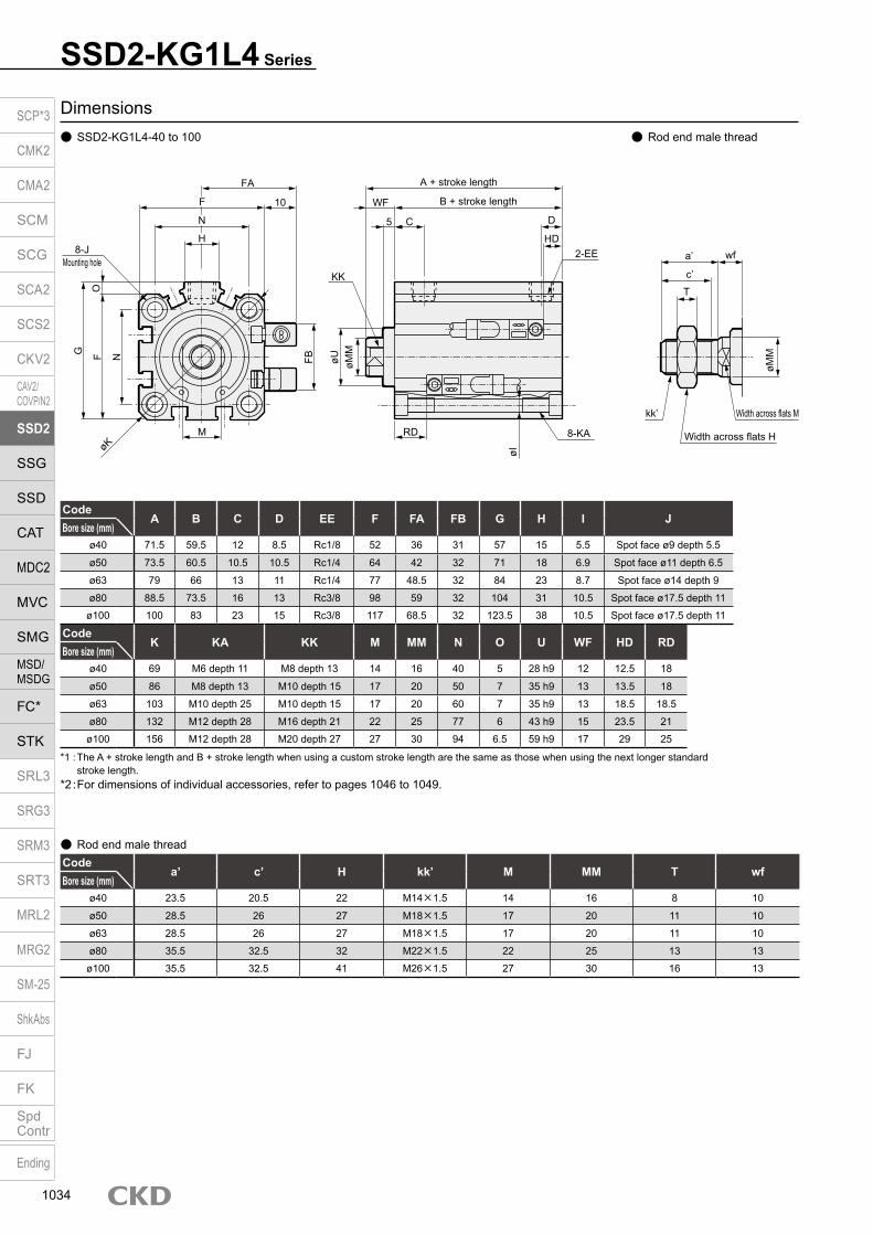
Dimensions SSD2-KG1L4-40 to 100
CodeA B C D EE F FA FB G H I J
Bore size (mm)ø40 71.5 59.5 12 8.5 Rc1/8 52 36 31 57 15 5.5 Spot face ø9 depth 5.5
ø50 73.5 60.5 10.5 10.5 Rc1/4 64 42 32 71 18 6.9 Spot face ø11 depth 6.5
ø63 79 66 13 11 Rc1/4 77 48.5 32 84 23 8.7 Spot face ø14 depth 9
ø80 88.5 73.5 16 13 Rc3/8 98 59 32 104 31 10.5 Spot face ø17.5 depth 11
ø100 100 83 23 15 Rc3/8 117 68.5 32 123.5 38 10.5 Spot face ø17.5 depth 11
CodeK KA KK M MM N O U WF HD RD
Bore size (mm)ø40 69 M6 depth 11 M8 depth 13 14 16 40 5 28 h9 12 12.5 18
ø50 86 M8 depth 13 M10 depth 15 17 20 50 7 35 h9 13 13.5 18
ø63 103 M10 depth 25 M10 depth 15 17 20 60 7 35 h9 13 18.5 18.5
ø80 132 M12 depth 28 M16 depth 21 22 25 77 6 43 h9 15 23.5 21
ø100 156 M12 depth 28 M20 depth 27 27 30 94 6.5 59 h9 17 29 25
*1 : The A + stroke length and B + stroke length when using a custom stroke length are the same as those when using the next longer standard stroke length.
*2 : For dimensions of individual accessories, refer to pages 1046 to 1049.
Rod end male thread
Codea’ c’ H kk’ M MM T wf
Bore size (mm)ø40 23.5 20.5 22 M14×1.5 14 16 8 10
ø50 28.5 26 27 M18×1.5 17 20 11 10
ø63 28.5 26 27 M18×1.5 17 20 11 10
ø80 35.5 32.5 32 M22×1.5 22 25 13 13
ø100 35.5 32.5 41 M26×1.5 27 30 16 13
Rod end male thread
SSD2-KG1L4 Series
A + stroke length
B + stroke length
D
8-KA
øI
RD
øMM
2-EE
WF
CHD
KK
FA
10F
N
H8-J
Mounting hole
G
OF N
øKM
FB øU
5
a’
c’
T
wf
øMM
kk’ Width across flats M
Width across flats H
SCP*3
CMK2
CMA2
SCM
SCG
SCA2
SCS2
CKV2
CAV2/COVP/N2
SSD2
SSG
SSD
CAT
MDC2
MVC
SMG
MSD/MSDG
FC*
STK
SRL3
SRG3
SRM3
SRT3
MRL2
MRG2
SM‑25
ShkAbs
FJ
FK
SpdContr
Ending
1034
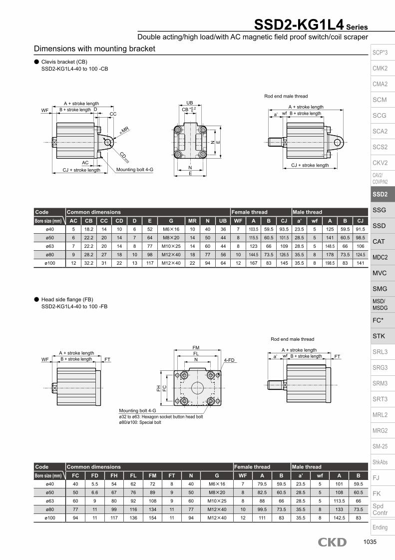
Dimensions with mounting bracket Clevis bracket (CB)
SSD2-KG1L4-40 to 100 -CB
Head side flange (FB) SSD2-KG1L4-40 to 100 -FB
SSD2-KG1L4 SeriesDouble acting/high load/with AC magnetic field proof switch/coil scraper
Code Common dimensions Female thread Male threadBore size (mm) AC CB CC CD D E G MR N UB WF A B CJ a’ wf A B CJ
ø40 5 18.2 14 10 6 52 M6×16 10 40 36 7 103.5 59.5 93.5 23.5 5 125 59.5 91.5
ø50 6 22.2 20 14 7 64 M8×20 14 50 44 8 115.5 60.5 101.5 28.5 5 141 60.5 98.5
ø63 7 22.2 20 14 8 77 M10×25 14 60 44 8 123 66 109 28.5 5 148.5 66 106
ø80 9 28.2 27 18 10 98 M12×40 18 77 56 10 144.5 73.5 126.5 35.5 8 178 73.5 124.5
ø100 12 32.2 31 22 13 117 M12×40 22 94 64 12 167 83 145 35.5 8 198.5 83 141
Code Common dimensions Female thread Male threadBore size (mm) FC FD FH FL FM FT N G WF A B a’ wf A B
ø40 40 5.5 54 62 72 8 40 M6×16 7 79.5 59.5 23.5 5 101 59.5
ø50 50 6.6 67 76 89 9 50 M8×20 8 82.5 60.5 28.5 5 108 60.5
ø63 60 9 80 92 108 9 60 M10×25 8 88 66 28.5 5 113.5 66
ø80 77 11 99 116 134 11 77 M12×40 10 99.5 73.5 35.5 8 133 73.5
ø100 94 11 117 136 154 11 94 M12×40 12 111 83 35.5 8 142.5 83
N
A + stroke length
Rod end male thread
B + stroke lengtha’ wf
A + stroke lengthB + stroke lengthWF
CJ + stroke lengthCJ + stroke length
CC
UBD
NE
E
CD H10
Mounting bolt 4-GAC
R MR
FH FC
A + stroke lengthB + stroke lengtha’ wfA + stroke length
B + stroke lengthWF FT4-FD
FLN
Mounting bolt 4-G
FM
FT
ø32 to ø63: Hexagon socket button head boltø80/ø100: Special bolt
Rod end male thread
CB + 0.2 0
SCP*3
CMK2
CMA2
SCM
SCG
SCA2
SCS2
CKV2
CAV2/COVP/N2
SSD2
SSG
SSD
CAT
MDC2
MVC
SMG
MSD/MSDG
FC*
STK
SRL3
SRG3
SRM3
SRT3
MRL2
MRG2
SM‑25
ShkAbs
FJ
FK
SpdContr
Ending
1035

Compact cylinder double acting/single rod
SSD2-P7*/P5* Series Bore size: ø12/ø16/ø20/ø25/ø32/ø40/ø50/ø63/ø80/ø100/ø125/
ø140/ø160JIS symbol
Specifications
*1: The ø32 bore size with a 5 mm stroke and without a switch has a port size of M5.
Item SSD2-P7*/P5*SSD2-L-P7*/P5* (with switch)
Bore size mm ø12 ø16 ø20 ø25 ø32 ø40 ø50 ø63 ø80 ø100 ø125 ø140 ø160Actuation Double actingWorking fluid Compressed airMax. working pressure MPa 1.0 (≈150 psi, 10 bar)Min. working pressure MPa 0.15 (≈22 psi, 1.5 bar) 0.1 (≈15 psi, 1 bar)Proof pressure MPa 1.6 (≈230 psi, 16 bar)Ambient temperature °C -10 (14°F) to 60 (140°F) (no freezing)Port size M5 Rc1/8 *1 Rc1/4 Rc3/8Pressure relief port size M5 Rc3/8Stroke tolerance mm +1.0
0+2.0
0
Working piston speed mm/s 50 to 500 50 to 300Cushion None Rubber cushionLubrication Not availableAllowable absorbed energy J 0.004 0.01 0.016 0.021 0.025 0.092 0.1 0.12 0.27 0.56 6.52 6.52 7.78
Stroke length
*1: Availability of custom stroke length Custom stroke length is available in 1 mm increments. Total length when using a custom stroke length is different between ø12 to ø100 and ø125 to ø160. Please be careful.
(ø12 to ø100) The dimensions of the total length with the custom stroke length are the same as the next longer standard stroke length.
(ø125 to ø160) Total length dimension with custom stroke length is handled as custom stroke dedicated length.
*2: Less than 5 mm with 1-color display switch and less than 10 mm with 2-color display, off-delay, T1* or T8* switch are not available.
Bore size (mm)
Standard stroke length (mm)
Max. stroke length (mm)
Min. stroke length (mm)
ø12 5/10/15/2025/30
30
1(5)
The value in ( ) is for types with one or two switches.
ø16ø20 5/10/15/20/25
30/35/40/45/5050
ø25ø32 5/10/15/20/25/30
35/40/45/50/75/100
100
ø40ø50 10/15/20
25/30/3540/45/5075/100
ø63ø80ø100ø125 10/20/30/40/50
75/100/125/150175/200/250/300
300ø140ø160
Custom stroke length SSD2-P7*, P5* Series
ItemStandard products
Standard stroke length body with spacerModel No. Refer to How to order.
Description A spacer is added to the standard stroke length body to adjust the stroke length in 1 mm increments.
Stroke range
Bore size Stroke range12/16 1 to 29
20 to 25 1 to 4932 to 100 1 to 99
Example of model No.
Model No.: SSD2-32-38-P7A +2 mm spacer is added to the SSD2-32-40-P7 standard cylinder to create 38 mm stroke length. B + stroke length is 73mm.
Switch specifications (F type switch) 1-color/2-color display
ItemProximity 2-wire Proximity 3-wire Proximity 2-wire Proximity 3-wire
F2S F3S F2H/F2VF2YH/F2YV
F3H/F3VF3PH/F3PV
(made to order)F3YH/F3YV
Applications Dedicated for programmable controller
For programmable controller, relay
Dedicated for programmable controller
For programmable controller, relay
Output method - NPN output - NPN output PNP output NPN outputPower supply voltage - 10 to 28 VDC - 10 to 28 VDC 4.5 to 28 VDC 10 to 28 VDCLoad voltage 10 to 30 VDC 30 VDC or less 10 to 30 VDC 24 VDC ±10% 30 VDC or lessLoad current 5 to 20 mA 50 mA or less 5 to 20 mA 50 mA or less
Indicator lamp LED(Lit when ON)
Yellow LED(Lit when ON)
Red/greenLED
(Lit when ON)
Yellow LED(Lit when ON)
Red/greenLED
(Lit when ON)Leakage current 1 mA or less 10 μA or less 1 mA or less 10 μA or lessWeight g 1 m:10 3 m:29
A + stroke length
B + stroke length
SCP*3
CMK2
CMA2
SCM
SCG
SCA2
SCS2
CKV2
CAV2/COVP/N2
SSD2
SSG
SSD
CAT
MDC2
MVC
SMG
MSD/MSDG
FC*
STK
SRL3
SRG3
SRM3
SRT3
MRL2
MRG2
SM‑25
ShkAbs
FJ
FK
SpdContr
Ending
1036
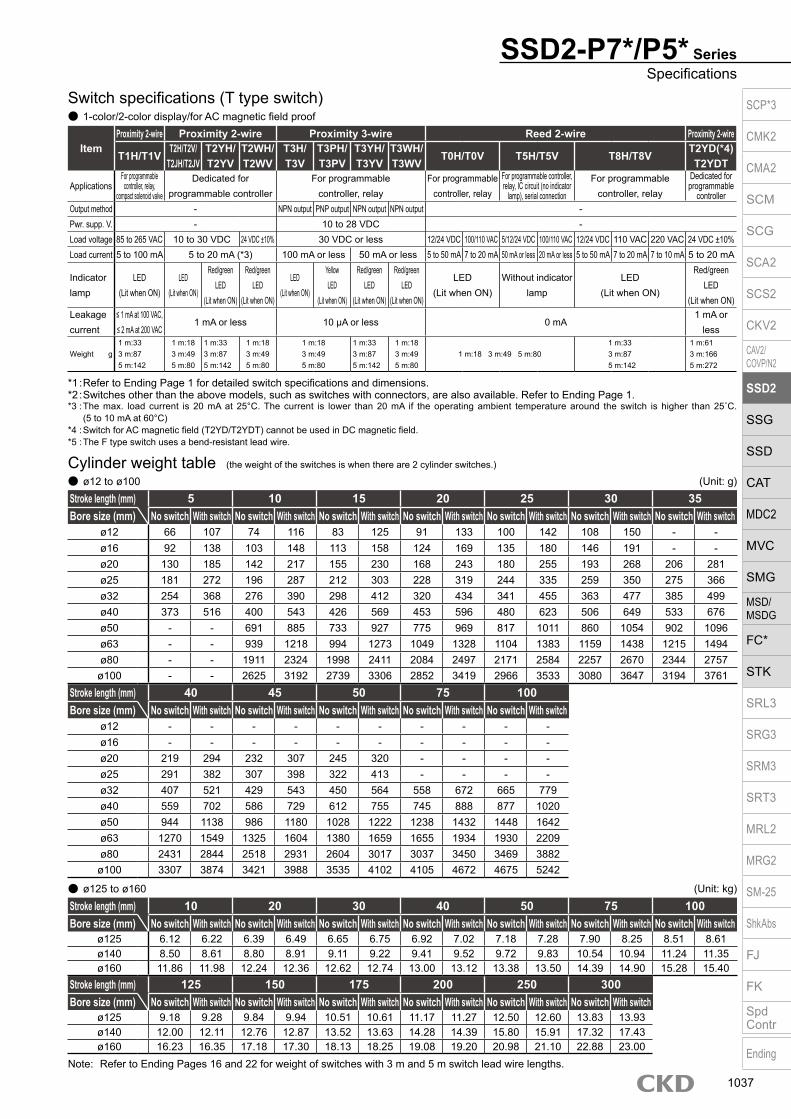
SSD2-P7*/P5* SeriesSpecifications
Switch specifications (T type switch) 1-color/2-color display/for AC magnetic field proof
ItemProximity 2-wire Proximity 2-wire Proximity 3-wire Reed 2-wire Proximity 2-wire
T1H/T1VT2H/T2V/
T2JH/T2JVT2YH/T2YV
T2WH/T2WV
T3H/T3V
T3PH/T3PV
T3YH/T3YV
T3WH/T3WV
T0H/T0V T5H/T5V T8H/T8VT2YD(*4)T2YDT
ApplicationsFor programmable
controller, relay, compact solenoid valve
Dedicated for programmable controller
For programmable controller, relay
For programmable controller, relay
For programmable controller, relay, IC circuit (no indicator
lamp), serial connection
For programmable controller, relay
Dedicated for programmable
controllerOutput method - NPN output PNP output NPN output NPN output -Pwr. supp. V. - 10 to 28 VDC -Load voltage 85 to 265 VAC 10 to 30 VDC 24 VDC ±10% 30 VDC or less 12/24 VDC 100/110 VAC 5/12/24 VDC 100/110 VAC 12/24 VDC 110 VAC 220 VAC 24 VDC ±10%Load current 5 to 100 mA 5 to 20 mA (*3) 100 mA or less 50 mA or less 5 to 50 mA 7 to 20 mA 50 mA or less 20 mA or less 5 to 50 mA 7 to 20 mA 7 to 10 mA 5 to 20 mA
Indicator lamp
LED(Lit when ON)
LED(Lit when ON)
Red/green LED
(Lit when ON)
Red/green LED
(Lit when ON)
LED (Lit when ON)
Yellow LED
(Lit when ON)
Red/green LED
(Lit when ON)
Red/green LED
(Lit when ON)
LED(Lit when ON)
Without indicator lamp
LED(Lit when ON)
Red/green LED
(Lit when ON)Leakage current
≤ 1 mA at 100 VAC, ≤ 2 mA at 200 VAC
1 mA or less 10 μA or less 0 mA1 mA or
less
Weight g1 m:333 m:875 m:142
1 m:183 m:495 m:80
1 m:333 m:875 m:142
1 m:183 m:495 m:80
1 m:183 m:495 m:80
1 m:333 m:875 m:142
1 m:183 m:495 m:80
1 m:18 3 m:49 5 m:801 m:333 m:875 m:142
1 m:613 m:1665 m:272
Stroke length (mm) 5 10 15 20 25 30 35Bore size (mm) No switch With switch No switch With switch No switch With switch No switch With switch No switch With switch No switch With switch No switch With switch
ø12 66 107 74 116 83 125 91 133 100 142 108 150 - -ø16 92 138 103 148 113 158 124 169 135 180 146 191 - -ø20 130 185 142 217 155 230 168 243 180 255 193 268 206 281ø25 181 272 196 287 212 303 228 319 244 335 259 350 275 366ø32 254 368 276 390 298 412 320 434 341 455 363 477 385 499ø40 373 516 400 543 426 569 453 596 480 623 506 649 533 676ø50 - - 691 885 733 927 775 969 817 1011 860 1054 902 1096ø63 - - 939 1218 994 1273 1049 1328 1104 1383 1159 1438 1215 1494ø80 - - 1911 2324 1998 2411 2084 2497 2171 2584 2257 2670 2344 2757ø100 - - 2625 3192 2739 3306 2852 3419 2966 3533 3080 3647 3194 3761
Cylinder weight table ø12 to ø100
(the weight of the switches is when there are 2 cylinder switches.)
(Unit: g)
*1 : Refer to Ending Page 1 for detailed switch specifications and dimensions. *2 : Switches other than the above models, such as switches with connectors, are also available. Refer to Ending Page 1. *3 : The max. load current is 20 mA at 25°C. The current is lower than 20 mA if the operating ambient temperature around the switch is higher than 25˚C.
(5 to 10 mA at 60°C) *4 : Switch for AC magnetic field (T2YD/T2YDT) cannot be used in DC magnetic field. *5 : The F type switch uses a bend-resistant lead wire.
Stroke length (mm) 10 20 30 40 50 75 100Bore size (mm) No switch With switch No switch With switch No switch With switch No switch With switch No switch With switch No switch With switch No switch With switch
ø125 6.12 6.22 6.39 6.49 6.65 6.75 6.92 7.02 7.18 7.28 7.90 8.25 8.51 8.61ø140 8.50 8.61 8.80 8.91 9.11 9.22 9.41 9.52 9.72 9.83 10.54 10.94 11.24 11.35ø160 11.86 11.98 12.24 12.36 12.62 12.74 13.00 13.12 13.38 13.50 14.39 14.90 15.28 15.40
Stroke length (mm) 125 150 175 200 250 300Bore size (mm) No switch With switch No switch With switch No switch With switch No switch With switch No switch With switch No switch With switch
ø125 9.18 9.28 9.84 9.94 10.51 10.61 11.17 11.27 12.50 12.60 13.83 13.93ø140 12.00 12.11 12.76 12.87 13.52 13.63 14.28 14.39 15.80 15.91 17.32 17.43ø160 16.23 16.35 17.18 17.30 18.13 18.25 19.08 19.20 20.98 21.10 22.88 23.00
(Unit: kg) ø125 to ø160
Note: Refer to Ending Pages 16 and 22 for weight of switches with 3 m and 5 m switch lead wire lengths.
Stroke length (mm) 40 45 50 75 100Bore size (mm) No switch With switch No switch With switch No switch With switch No switch With switch No switch With switch
ø12 - - - - - - - - - -ø16 - - - - - - - - - -ø20 219 294 232 307 245 320 - - - -ø25 291 382 307 398 322 413 - - - -ø32 407 521 429 543 450 564 558 672 665 779ø40 559 702 586 729 612 755 745 888 877 1020ø50 944 1138 986 1180 1028 1222 1238 1432 1448 1642ø63 1270 1549 1325 1604 1380 1659 1655 1934 1930 2209ø80 2431 2844 2518 2931 2604 3017 3037 3450 3469 3882ø100 3307 3874 3421 3988 3535 4102 4105 4672 4675 5242
SCP*3
CMK2
CMA2
SCM
SCG
SCA2
SCS2
CKV2
CAV2/COVP/N2
SSD2
SSG
SSD
CAT
MDC2
MVC
SMG
MSD/MSDG
FC*
STK
SRL3
SRG3
SRM3
SRT3
MRL2
MRG2
SM‑25
ShkAbs
FJ
FK
SpdContr
Ending
1037

SSD2-P7*/P5* Series
Model No.A
How to orderWithout switch (without magnet for switch)
With switch (built-in magnet for switch)12 N5
Clean-room specifications*6
G
Bore size
B
12
*2*3*4*5
D Switch* indicates the lead wire length.
Stroke length*1
C
Switch quantityE
OptionF
5 R N
Code DescriptionModel No.SSD2 Double acting/single rod
SSD2-L Double acting/single rod/with switch
Bore size (mm)12 ø1216 ø1620 ø2025 ø2532 ø3240 ø4050 ø5063 ø6380 ø80100 ø100125 ø125140 ø140160 ø160
Stroke length (mm)
Refer to the stroke length table on the following page.
* Lead wire lengthBlank 1 m (standard)
3 3 m (option)5 5 m (option) *8
Switch quantityR 1 on rod sideH 1 on head sideD 2
OptionBlank Rod end female thread
N Rod end male thread
Clean-room specificationsStructure Material limitations
P7 Exhaust port -P71 Vacuum treatment -P5 Exhaust port Copper/silicon/halogen-based materials (fluorine, chlorine, bromine) prohibited (custom)
P51 Vacuum treatment Copper/silicon/halogen-based materials (fluorine, chlorine, bromine) prohibited (custom)
Switch model No.Lead wire Lead wire
Conta
ct Voltage Display Lead wire Bore sizeStraight L-shaped ACDC 121620253240506380100 125 140160
- F2S
Pro
xim
ity
1-color display
2-wire - F3S 3-wire
F2H* F2V* 2-wire F3H* F3V* 3-wire
F3PH* F3PV* 1-color display (PNP output) 3-wire F2YH* F2YV*
2-color display2-wire
F3YH* F3YV* 3-wire T0H* T0V*
Ree
d 1-color display2-wire
T5H* T5V* Without indicator lamp T8H* T8V* 1-color display T1H* T1V*
Pro
xim
ity
1-color display
2-wire
T2H* T2V* T3H* T3V*
3-wire
T3PH* T3PV* 1-color display (PNP output) (custom) T2WH* T2WV*
2-color display
2-wire
T2YH* T2YV* T3WH* T3WV*
3-wire
T3YH* T3YV* T2YD* - 2-color display
AC magnetic field 2-wire
T2YDT* - T2JH* T2JV* 1-color display off-delay 2-wire
A
B
C
E
G
F
Precautions for model No. selection*1 : Availability of custom stroke length
Custom stroke length is available in 1 mm increments. (Less than 5 mm with switch is not available.) Total length when using a custom stroke length is different between ø12 to ø100 and ø125 to ø160. Please be careful.
[ø12 to ø100] The dimensions of the total length with the custom stroke length are the
same as the next longer standard stroke length. [ø125 to ø160] Dedicated custom stroke length.*2 : The T2YD* switch cannot be mounted on the ø12 and ø16 bore sizes.*3 : The T8* switch cannot be mounted on the ø12 to ø32 bore sizes.*4 : The F type switch can only be mounted on the piping port surface of bore
sizes ø20 and ø25.*5 : The F type switch with L type lead wire on ø20 models
cannot be selected on stroke lengths of 15 mm or under.*6 : “P5” and “P51” are made-to-order products.*7 : Refer to pages 750 and 751 for combinations of variations/
options.*8 : F type switch cannot be selected.
[Example of model No.]SSD2-L-12-5-T0H-R-NP7A Model : Compact cylinder, standardB Bore size : ø12 mmC Stroke length : 5 mmD Switch model No. : Reed switch T0H, lead wire length 1 mE Switch quantity : 1 on rod sideF Option : Rod end male threadG Clean-room specifications : Exhaust port
D
SSD2
SSD2-L
P7
P7T0H
SCP*3
CMK2
CMA2
SCM
SCG
SCA2
SCS2
CKV2
CAV2/COVP/N2
SSD2
SSG
SSD
CAT
MDC2
MVC
SMG
MSD/MSDG
FC*
STK
SRL3
SRG3
SRM3
SRT3
MRL2
MRG2
SM‑25
ShkAbs
FJ
FK
SpdContr
Ending
1038

Stroke length (mm)Applicable bore size
ø12 ø16 ø20 ø25 ø32 ø40 ø50 ø63 ø80 ø100 ø125 ø140 ø160
Sta
ndar
d st
roke
leng
th
5 10 15 20 25 30 35 40 45 50 75
100 125 150 175 200 250 300
Min. stroke length (mm) 1Max. stroke length (mm) 30 50 100 300Custom stroke length *1 In 1 mm increments
[Stroke length table]
SSD2-P7*/P5* SeriesHow to order
Theoretical thrust table (Unit: N)
Bore size (mm)
Operating direction
Working pressure MPa0.1 0.15 0.2 0.3 0.4 0.5 0.6 0.7 0.8 0.9 1.0
ø12Push - 17.0 22.6 33.9 45.2 56.5 67.9 79.2 90.5 1.02×10² 1.13×10²
Pull - 12.7 17.0 25.4 33.9 42.4 50.9 59.4 67.9 76.3 84.8
ø16Push - 30.2 40.2 60.3 80.4 1.01×10² 1.21×10² 1.41×10² 1.61×10² 1.81×10² 2.01×10²
Pull - 22.6 30.2 45.2 60.3 75.4 90.5 1.06×10² 1.21×10² 1.36×10² 1.51×10²
ø20Push - 47.1 62.8 94.2 1.26×10² 1.57×10² 1.88×10² 2.20×10² 2.51×10² 2.83×10² 3.14×10²
Pull - 35.3 47.1 70.7 94.2 1.18×10² 1.41×10² 1.65×10² 1.88×10² 2.12×10² 2.36×10²
ø25Push - 73.6 98.2 1.47×10² 1.96×10² 2.45×10² 2.95×10² 3.44×10² 3.93×10² 4.42×10² 4.91×10²
Pull - 56.7 75.6 1.13×10² 1.51×10² 1.89×10² 2.27×10² 2.64×10² 3.02×10² 3.40×10² 3.78×10²
ø32Push - 1.21×10² 1.61×10² 2.41×10² 3.22×10² 4.02×10² 4.83×10² 5.63×10² 6.43×10² 7.24×10² 8.04×10²
Pull - 90.5 1.21×10² 1.81×10² 2.41×10² 3.02×10² 3.62×10² 4.22×10² 4.83×10² 5.43×10² 6.03×10²
ø40Push - 1.88×10² 2.51×10² 3.77×10² 5.03×10² 6.28×10² 7.54×10² 8.80×10² 1.01×10³ 1.13×10³ 1.26×10³
Pull - 1.58×10² 2.11×10² 3.17×10² 4.22×10² 5.28×10² 6.33×10² 7.39×10² 8.44×10² 9.50×10² 1.06×10³
ø50Push - 2.95×10² 3.93×10² 5.89×10² 7.85×10² 9.82×10² 1.18×10³ 1.37×10³ 1.57×10³ 1.77×10³ 1.96×10³
Pull - 2.47×10² 3.30×10² 4.95×10² 6.60×10² 8.25×10² 9.90×10² 1.15×10³ 1.32×10³ 1.48×10³ 1.65×10³
ø63Push 3.12×10² 4.68×10² 6.23×10² 9.35×10² 1.25×10³ 1.56×10³ 1.87×10³ 2.18×10³ 2.49×10³ 2.81×10³ 3.12×10³
Pull 2.80×10² 4.20×10² 5.61×10² 8.41×10² 1.12×10³ 1.40×10³ 1.68×10³ 1.96×10³ 2.24×10³ 2.52×10³ 2.80×10³
ø80Push 5.03×10² 7.54×10² 1.01×10³ 1.51×10³ 2.01×10³ 2.51×10³ 3.02×10³ 3.52×10³ 4.02×10³ 4.52×10³ 5.03×10³
Pull 4.54×10² 6.80×10² 9.07×10² 1.36×10³ 1.81×10³ 2.27×10³ 2.72×10³ 3.17×10³ 3.63×10³ 4.08×10³ 4.54×10³
ø100Push 7.85×10² 1.18×10³ 1.57×10³ 2.36×10³ 3.14×10³ 3.93×10³ 4.71×10³ 5.50×10³ 6.28×10³ 7.07×10³ 7.85×10³
Pull 7.15×10² 1.07×10³ 1.43×10³ 2.14×10³ 2.86×10³ 3.57×10³ 4.29×10³ 5.00×10³ 5.72×10³ 6.43×10³ 7.15×10³
ø125Push 1.23×10³ 1.84×10³ 2.45×10³ 3.68×10³ 4.91×10³ 6.14×10³ 7.36×10³ 8.59×10³ 9.82×10³ 1.10×10⁴ 1.23×10⁴
Pull 1.13×10³ 1.70×10³ 2.26×10³ 3.39×10³ 4.52×10³ 5.65×10³ 6.79×10³ 7.92×10³ 9.05×10³ 1.02×10⁴ 1.13×10⁴
ø140Push 1.54×10³ 2.31×10³ 3.08×10³ 4.62×10³ 6.16×10³ 7.70×10³ 9.24×10³ 1.08×10⁴ 1.23×10⁴ 1.39×10⁴ 1.54×10⁴
Pull 1.44×10³ 2.16×10³ 2.89×10³ 4.33×10³ 5.77×10³ 7.22×10³ 8.66×10³ 1.01×10⁴ 1.15×10⁴ 1.30×10⁴ 1.44×10⁴
ø160Push 2.01×10³ 3.02×10³ 4.02×10³ 6.03×10³ 8.04×10³ 1.01×10⁴ 1.21×10⁴ 1.41×10⁴ 1.61×10⁴ 1.81×10⁴ 2.01×10⁴
Pull 1.88×10³ 2.83×10³ 3.77×10³ 5.65×10³ 7.54×10³ 9.42×10³ 1.13×10⁴ 1.32×10⁴ 1.51×10⁴ 1.70×10⁴ 1.88×104
SCP*3
CMK2
CMA2
SCM
SCG
SCA2
SCS2
CKV2
CAV2/COVP/N2
SSD2
SSG
SSD
CAT
MDC2
MVC
SMG
MSD/MSDG
FC*
STK
SRL3
SRG3
SRM3
SRT3
MRL2
MRG2
SM‑25
ShkAbs
FJ
FK
SpdContr
Ending
1039

Dimensions SSD2-L-12 to 25-P7*/P5* (with switch/TOH/V, T5H/V, T2H/V, T3H/V) Rod end male thread
Code Common dimensions with switch Reed T0H/T0V,T5H/T5V Proximity T2H/T2V, T3H/T3V Proximity T2WH/T2WV,
T3WH/T3WVProximity F2H/F2V, F3H/F3V,
F2YH/F2YV, F3YH/F3YV Proximity F2S/F3SBore size (mm) M MM N WF HD RD HD RD HD RD HD RD HD RD
ø12 5 6 15.5 3.5 4 9 4 9 6 11 - - - -
ø16 6 8 20 3.5 2 11.5 2 11.5 3 13.5 - - - -ø20 8 10 25.5 4.5 6 14.5 6 14.5 8 16.5 10.5 19 9.5 18ø25 10 12 28 5 8 16 8 16 10 18 12.5 20 11.5 19
Codea’ c’ H kk’ M MM T wf
Bore size (mm)ø12 10.5 9 8 M5 5 6 3.2 3.5
ø16 12 10 10 M6 6 8 3.6 3.5
ø20 14 12 13 M8 8 10 5 4.5
ø25 17.5 15 17 M10×1.25 10 12 6 5
Rod end male thread
ø12/ø16
ø20/ø25
Code Without switch Common dimensions with switch
A *1 B *1 A B C DLA LB
Q *4 EE F FA *3 FB I J K KA KKBore size (mm) ≤5 St Over 5 st ≤5 St Over 5 st
ø12 30.5 27 35.5 32 5.5 5.5 4 0 2 0 16.5(16) M5 25 13(16.5) 4.5 3.5 6.5 spot face depth 3.5 32 M4 depth 7 M3 depth 6ø16 30.5 27 35.5 32 5.5 5.5 6 0 0 0 16.5 M5 29 15(18.5) 4.5 3.5 6.5 spot face depth 3.5 38 M4 depth 7 M4 depth 8ø20 34 29.5 44 39.5 5.5 7 - - - - 16.5 M5 36 18.5(22) 12.5 5.5 9 spot face depth 5.5 47 M6 depth 11 M5 depth 7ø25 37.5 32.5 47.5 42.5 7 8.5 - - - - 18 M5 40 20.5(24) 13.5 5.5 9 spot face depth 5.5 51 M6 depth 11 M6 depth 12
SSD2-12 to 25-P7*/P5* (without switch)
SSD2-P7*/P5* Series
Code Proximity T2YH/T2YVT3YH/T3YV/T2JH/T2JV Reed T8H/T8V AC magnetic field proof
T2YD/T2YDT/T1H/T1V
Bore size (mm) HD RD HD RD HD RDø12 - - - - - -
ø16 - - - - - -ø20 5 13.5 - - - -ø25 6.5 15 - - - -
*1 : To calculate A+ stroke length or B+ stroke length when using custom stroke length, apply the next longer standard stroke length (instead of the custom stroke length) to the stroke length value. (Example) If the custom stroke length is 7 mm, apply the standard stroke length of 10 mm.
*2 : HD and RD dimensions for 5 mm stroke length differ from these dimensions according to the setting.
*3 : Dimensions in ( ) of FA are for the radial lead wire.*4 : Dimensions in ( ) of code Q are when the value is for a 5 mm stroke without
switch.*5 : Only F type switch is available for the ø20 or ø25 piping port surface.
a’c’
T
wf
øMM
kk’Width across flats M
Width across flats H
8-JMounting hole
øK
F N
M
N
F
FB
øMM
WF
C
D
HD
A + stroke length
B + stroke length
FA
øK
F N
øMM
øI
A + stroke length
B + stroke length
Q
M5(Pressure relief port)
LB
LA
øI
*3
D8-JMounting hole N
FQ
C
WF
M
2-EE
8-KA
KK
KK
M5(Pressure relief port)
5 mm stroke length
RD 8-KA
SCP*3
CMK2
CMA2
SCM
SCG
SCA2
SCS2
CKV2
CAV2/COVP/N2
SSD2
SSG
SSD
CAT
MDC2
MVC
SMG
MSD/MSDG
FC*
STK
SRL3
SRG3
SRM3
SRT3
MRL2
MRG2
SM‑25
ShkAbs
FJ
FK
SpdContr
Ending
1040
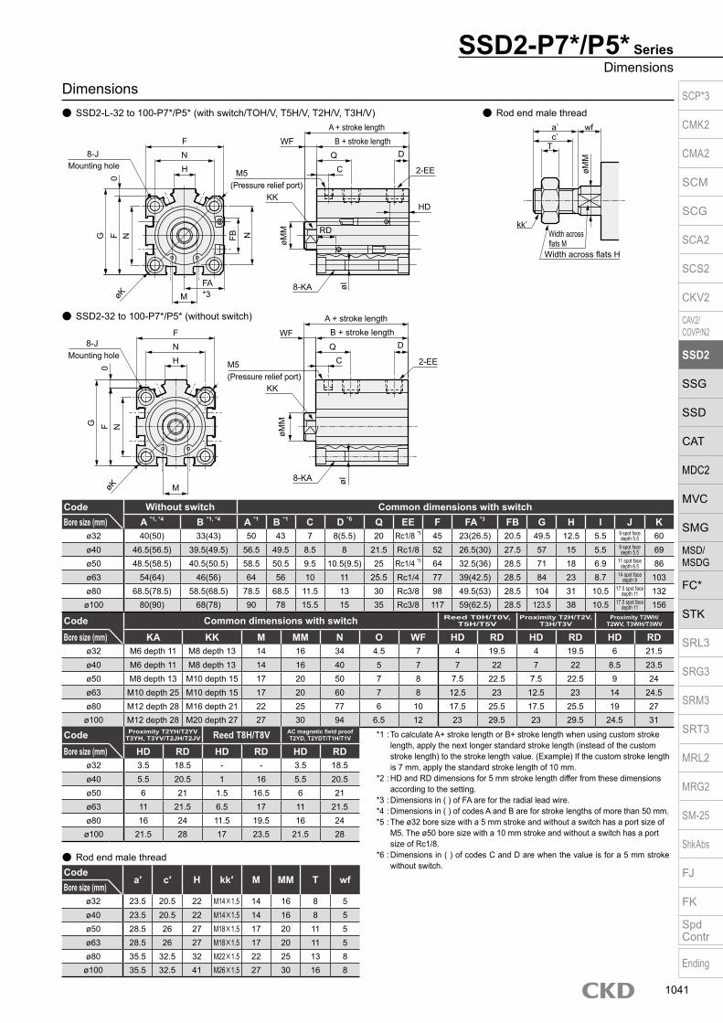
Dimensions SSD2-L-32 to 100-P7*/P5* (with switch/TOH/V, T5H/V, T2H/V, T3H/V) Rod end male thread
Code Common dimensions with switch Reed T0H/T0V,T5H/T5V
Proximity T2H/T2V, T3H/T3V
Proximity T2WH/ T2WV, T3WH/T3WV
Bore size (mm) KA KK M MM N O WF HD RD HD RD HD RDø32 M6 depth 11 M8 depth 13 14 16 34 4.5 7 4 19.5 4 19.5 6 21.5ø40 M6 depth 11 M8 depth 13 14 16 40 5 7 7 22 7 22 8.5 23.5ø50 M8 depth 13 M10 depth 15 17 20 50 7 8 7.5 22.5 7.5 22.5 9 24ø63 M10 depth 25 M10 depth 15 17 20 60 7 8 12.5 23 12.5 23 14 24.5ø80 M12 depth 28 M16 depth 21 22 25 77 6 10 17.5 25.5 17.5 25.5 19 27
ø100 M12 depth 28 M20 depth 27 27 30 94 6.5 12 23 29.5 23 29.5 24.5 31
SSD2-32 to 100-P7*/P5* (without switch)
Code Without switch Common dimensions with switchBore size (mm) A *1, *4 B *1, *4 A *1 B *1 C D *6 Q EE F FA *3 FB G H I J K
ø32 40(50) 33(43) 50 43 7 8(5.5) 20 Rc1/8 *5 45 23(26.5) 20.5 49.5 12.5 5.5 9 spot face depth 5.5 60
ø40 46.5(56.5) 39.5(49.5) 56.5 49.5 8.5 8 21.5 Rc1/8 52 26.5(30) 27.5 57 15 5.5 9 spot face depth 5.5 69
ø50 48.5(58.5) 40.5(50.5) 58.5 50.5 9.5 10.5(9.5) 25 Rc1/4 *5 64 32.5(36) 28.5 71 18 6.9 11 spot face depth 6.5 86
ø63 54(64) 46(56) 64 56 10 11 25.5 Rc1/4 77 39(42.5) 28.5 84 23 8.7 14 spot face depth 9 103
ø80 68.5(78.5) 58.5(68.5) 78.5 68.5 11.5 13 30 Rc3/8 98 49.5(53) 28.5 104 31 10.5 17.5 spot face depth 11 132
ø100 80(90) 68(78) 90 78 15.5 15 35 Rc3/8 117 59(62.5) 28.5 123.5 38 10.5 17.5 spot face depth 11 156
SSD2-P7*/P5* SeriesDimensions
Code Proximity T2YH/T2YVT3YH, T3YV/T2JH/T2JV Reed T8H/T8V AC magnetic field proof
T2YD, T2YDT/T1H/T1V
Bore size (mm) HD RD HD RD HD RDø32 3.5 18.5 - - 3.5 18.5ø40 5.5 20.5 1 16 5.5 20.5ø50 6 21 1.5 16.5 6 21ø63 11 21.5 6.5 17 11 21.5ø80 16 24 11.5 19.5 16 24
ø100 21.5 28 17 23.5 21.5 28
Codea′ c′ H kk′ M MM T wf
Bore size (mm)ø32 23.5 20.5 22 M14×1.5 14 16 8 5ø40 23.5 20.5 22 M14×1.5 14 16 8 5ø50 28.5 26 27 M18×1.5 17 20 11 5ø63 28.5 26 27 M18×1.5 17 20 11 5ø80 35.5 32.5 32 M22×1.5 22 25 13 8ø100 35.5 32.5 41 M26×1.5 27 30 16 8
Rod end male thread
*1 : To calculate A+ stroke length or B+ stroke length when using custom stroke length, apply the next longer standard stroke length (instead of the custom stroke length) to the stroke length value. (Example) If the custom stroke length is 7 mm, apply the standard stroke length of 10 mm.
*2 : HD and RD dimensions for 5 mm stroke length differ from these dimensions according to the setting.
*3 : Dimensions in ( ) of FA are for the radial lead wire.*4 : Dimensions in ( ) of codes A and B are for stroke lengths of more than 50 mm.*5 : The ø32 bore size with a 5 mm stroke and without a switch has a port size of
M5. The ø50 bore size with a 10 mm stroke and without a switch has a port size of Rc1/8.
*6 : Dimensions in ( ) of codes C and D are when the value is for a 5 mm stroke without switch.
a’c’
T
wf
øMM
kk’Width across flats M
Width across flats H
*3øK
G N
M
N
0F FB
FA
F
H
8-JMounting hole
øMM
WFQ D
HD
øI
A + stroke lengthB + stroke length
øK
øMM
WFQ D
øI
A + stroke lengthB + stroke length
N
M
N
0F
F
H
8-JMounting hole
C
N
C
G
RD
M5(Pressure relief port)
M5(Pressure relief port)
8-KA
2-EE
2-EE
8-KA
KK
KK
SCP*3
CMK2
CMA2
SCM
SCG
SCA2
SCS2
CKV2
CAV2/COVP/N2
SSD2
SSG
SSD
CAT
MDC2
MVC
SMG
MSD/MSDG
FC*
STK
SRL3
SRG3
SRM3
SRT3
MRL2
MRG2
SM‑25
ShkAbs
FJ
FK
SpdContr
Ending
1041
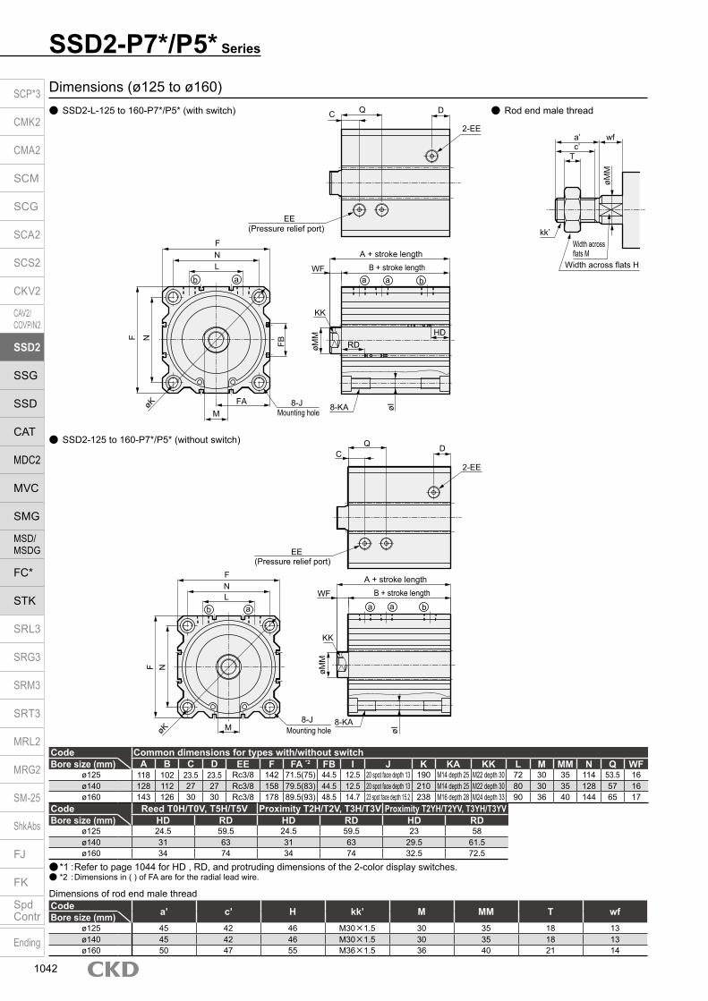
SSD2-P7*/P5* Series
Rod end male thread
Dimensions (ø125 to ø160) SSD2-L-125 to 160-P7*/P5* (with switch)
SSD2-125 to 160-P7*/P5* (without switch)
Code Common dimensions for types with/without switchBore size (mm) A B C D EE F FA *2 FB I J K KA KK L M MM N Q WF
ø125 118 102 23.5 23.5 Rc3/8 142 71.5(75) 44.5 12.5 20 spot face depth 13 190 M14 depth 25 M22 depth 30 72 30 35 114 53.5 16ø140 128 112 27 27 Rc3/8 158 79.5(83) 44.5 12.5 20 spot face depth 13 210 M14 depth 25 M22 depth 30 80 30 35 128 57 16ø160 143 126 30 30 Rc3/8 178 89.5(93) 48.5 14.7 23 spot face depth 15.2 238 M16 depth 28 M24 depth 33 90 36 40 144 65 17
Code Reed T0H/T0V, T5H/T5V Proximity T2H/T2V, T3H/T3V Proximity T2YH/T2YV, T3YH/T3YVBore size (mm) HD RD HD RD HD RD
ø125 24.5 59.5 24.5 59.5 23 58ø140 31 63 31 63 29.5 61.5ø160 34 74 34 74 32.5 72.5
*1 : Refer to page 1044 for HD , RD, and protruding dimensions of the 2-color display switches. *2 : Dimensions in ( ) of FA are for the radial lead wire.
Code a’ c’ H kk’ M MM T wfBore size (mm)ø125 45 42 46 M30×1.5 30 35 18 13ø140 45 42 46 M30×1.5 30 35 18 13ø160 50 47 55 M36×1.5 36 40 21 14
Dimensions of rod end male thread
a’c’
T
wf
øMM
kk’Width across flats M
Width across flats H
QC D
2-EE
EE(Pressure relief port)
A + stroke lengthB + stroke lengthWF
KKøM
M
8-KA øI
HD
a a b
RD
FNL
abFB
8-JMounting hole
FAM
øK
F N
QC
D
2-EE
EE(Pressure relief port)
A + stroke lengthB + stroke lengthWF
KK
øMM
8-KA
øI
a a b
FNL
ab
8-JMounting holeMøK
F N
SCP*3
CMK2
CMA2
SCM
SCG
SCA2
SCS2
CKV2
CAV2/COVP/N2
SSD2
SSG
SSD
CAT
MDC2
MVC
SMG
MSD/MSDG
FC*
STK
SRL3
SRG3
SRM3
SRT3
MRL2
MRG2
SM‑25
ShkAbs
FJ
FK
SpdContr
Ending
1042

M E M OM E M OSCP*3
CMK2
CMA2
SCM
SCG
SCA2
SCS2
CKV2
CAV2/COVP/N2
SSD2
SSG
SSD
CAT
MDC2
MVC
SMG
MSD/MSDG
FC*
STK
SRL3
SRG3
SRM3
SRT3
MRL2
MRG2
SM‑25
ShkAbs
FJ
FK
SpdContr
Ending
1043

SSD2 Series
SSD2 Series common dimensions (with 2-color display, off-delay, AC magnetic field, T1* and T8* switches) SSD2-L-12 to 100 (with 2-color display, off-delay, T8* switches/T2YH/V, T3YH/V, T2JH/V, T8H/V)
· ø20/ø25 · ø32 to ø100
· ø20/ø25 · ø32 to ø100
CodeFA FB
SSD2-L, XL,YL SSD2-DL *1 SSD2 (Long stroke) -L *2 SSD2-ML SSD2-GL SSD2-G5LBore size (mm) RD HD RD HD RD HD RD HD RD HD RD HD
ø12 23.8 8 - - 1.5 4 3 1 - - - - - -
ø16 25.8 8 - - 0.5 3.5 2.5 1.5 - - - - - -
ø20 29.3 16 6.5 2 5 8 14(8.5) 5.5(11) 10 1.5 16.5 2 - -
ø25 31.3 17 8.5 3 8 10 17.5(10.5) 5(12.5) 13 1.5 18.5 3 - -
ø32 33.8 24 8.5 3.5 7.5 9.5 16(8) 8(14.5) 17.5 2 18.5 3.5 19.5 3.5
ø40 37.3 31 10.5 5.5 10.5 15 24.5(15) 8(17.5) 10.5 5.5 10.5 5.5 20.5 5.5
ø50 43.3 32 11 6 11 15 24.5(16) 8.5(17.5) 11 6 11 6 21 6
ø63 49.8 32 11.5 11 11.5 16.5 18.5(13.5) 16(21.5) 11.5 11 11.5 11 21.5 11
ø80 60.3 32 14 16 14 21.5 22.5(17.5) 20.5(26.5) - - 14 16 28 16
ø100 69.8 32 18 21.5 18 27 26.5(21.5) 26.5(32) - - 18 21.5 33.5 21.5
*1: The port surface with the mark is the “RD side”.*2: Dimensions in ( ) are for stroke length over 100 for ø20, stroke length over 150 for ø25 to ø50, and stroke length over 200 for ø63 to ø100.
CodeFA FB
T2YH/V, T3YH/V, T2JH/V T8H/VSSD2-L, XL,YL
*1SSD2-DL
*2SSD2 (Long) -L
SSD2-ML
SSD2-GLSSD2-G5L
SSD2-L, XL,YL, GL
*1SSD2-DL SSD2-ML
*2SSD2 (Long) -L SSD2-G5L
Bore size (mm) RD HD RD HD RD HD RD HD RD HD RD HD RD HD RD HD RD HD RD HD RD HDø12 18.8 8 - - 1 3.5 3 1 - - - - - - - - - - - - - - - -
ø16 20.8 8 - - 0.5 3.5 2.5 1.5 - - - - - - - - - - - - - - - -
ø20 24.3 16 6.5 2 5 8 14(8.5) 5.5(11) 10 1.5 16.5 2 - - - - 0.5 3.5 - - 9.5(4) 0(6.5) - -
ø25 26.3 17 8.5 3 8 10 17.5(10.5) 5(12.5) 13 1.5 18.5 3 - - - - 1.5 5.5 - - 13(6) 0(8) - -
ø32 28.8 24 8.5 3.5 7.5 9.5 16(8) 8(14.5) 17.5 2 18.5 3.5 19.5 3.5 - - 3 5 - - 11.5(4) 2.5(10) - -
ø40 32.3 31 10.5 5.5 10.5 15 24.5(15) 8(17.5) 10.5 5.5 10.5 5.5 20.5 5.5 6 1 6 10.5 6 1 20(10.5) 3.5(13) 16 1
ø50 38.3 32 11 6 11 15 24.5(16) 8.5(17.5) 11 6 11 6 21 6 6.5 1.5 6.5 10.5 6.5 1.5 19.5(11) 4(13) 16.5 1.5
ø63 44.8 32 11.5 11 11.5 16.5 18.5(13.5) 16(21.5) 11.5 11 11.5 11 21.5 11 7 6.5 7 12 7 6.5 13.5(8.5) 11.5(17) 17 6.5
ø80 55.3 32 14 16 14 21.5 22.5(17.5) 20.5(26.5) - - 14 16 28 16 9.5 11.5 9.5 17 - - 17.5(12.5) 16(22) 23.5 11.5
ø100 64.8 32 18 21.5 18 27 26.5(21.5) 26.5(32) - - 18 21.5 33.5 21.5 13.5 17 13.5 22.5 - - 21.5(16.5) 22(27.5) 29 17
SSD2-L-12 to 100 (for AC magnetic field, with T1* switch, T2YD, T2YDT, T1H/V)
· ø12/ø16
· ø12/ø16
FA
HD
RD
FB
FA
HD
RD
FB
FA
FB
A + stroke length
B + stroke length
HD
RD
FA
HD
RD
FB
FA
HD
RD
FB
FA
FB
A + stroke length
B + stroke length
HD
RD
SCP*3
CMK2
CMA2
SCM
SCG
SCA2
SCS2
CKV2
CAV2/COVP/N2
SSD2
SSG
SSD
CAT
MDC2
MVC
SMG
MSD/MSDG
FC*
STK
SRL3
SRG3
SRM3
SRT3
MRL2
MRG2
SM-25
ShkAbs
FJ
FK
SpdContr
Ending
1044

SSD2-K SeriesSSD2 Series common switch dimensions
SSD2-K Series common dimensions (with 2-color display, off-delay, AC magnetic field, T1* and T8* switches) SSD2-KL-20 to 100 (with 2-color display, off-delay, T8* switches/T2YH/V, T3YH/V, T2JH/V, T8H/V)
· ø20/ø25 · ø32 to ø100
SSD2-KL-20 to 100 (for AC magnetic field, with T1* switch, T2YD, T2YDT, T1H/V)
· ø20/ø25 · ø32 to ø100
CodeFA FB
T2YH/V, T3YH/V, T2JH/V T8H/VBore size (mm) RD HD RD HD
ø20 24.3 16 8 5.5 - -
ø25 26.3 17 11.5 5 - -
ø32 28.8 24 14 8 - -
ø40 32.3 31 18 8 13.5 3.5
ø50 38.3 32 18.5 8.5 14 4
ø63 44.8 32 16.5 16 12 11.5
ø80 55.3 32 19 20.5 14.5 16
ø100 64.8 32 23 26.5 18.5 22
CodeFA FB RD HD
Bore size (mm)ø20 29.3 16 8 5.5
ø25 31.3 17 11.5 5
ø32 33.8 24 14 8
ø40 37.3 31 18 8
ø50 43.3 32 18.5 8.5
ø63 49.8 32 16.5 16
ø80 60.3 32 19 20.5
ø100 60.8 32 23 26.5
FA
HD
RD
FB
FA
HD
RD
FB
FA
HD
RD
FB
FA
HD
RD
FB
SCP*3
CMK2
CMA2
SCM
SCG
SCA2
SCS2
CKV2
CAV2/COVP/N2
SSD2
SSG
SSD
CAT
MDC2
MVC
SMG
MSD/MSDG
FC*
STK
SRL3
SRG3
SRM3
SRT3
MRL2
MRG2
SM‑25
ShkAbs
FJ
FK
SpdContr
Ending
1045

Dimensions (Mounting bracket: LB) Axial foot (LB)
· ø12 to ø25
SSD2 Series
*1: Hex socket mounting bolts are included.
Model No. Bore size AB AC AD AE AG AH AK AT AU B D N TR TS WF wf a’ Weight (g)SSD2-LB-12 ø12 5 4.5 - - 29.5 17 12.5 2 8 M4×10 8 15.5 34 44 13.5 13.5 10.5 51
SSD2-LB-16 ø16 5 4.5 - - 33.5 19 13 2 8 M4×10 10 20 38 48 13.5 13.5 12 61
SSD2-LB-20 ø20 7 6.5 - - 42 24 15 3.2 9.2 M6×16 12 25.5 48 62 14.5 14.5 14 161
SSD2-LB-25 ø25 7 6.5 - - 46 26 16.5 3.2 10.7 M6×16 14 28 52 66 15 15 17.5 176
SSD2-LB-32 ø32 7 7 18.5 13 57 30 17 3.2 11.2 M6×16 - 34 57 71 17 15 23.5 107
SSD2-LB-40 ø40 7 7 18 13 64 33 18.2 3.2 11.2 M6×16 - 40 64 78 17 15 23.5 121
SSD2-LB-50 ø50 9 9 22 14 78 39 22.7 3.2 14.7 M8×20 - 50 79 95 18 15 28.5 201
SSD2-LB-63 ø63 11 11 26 16 91.5 46 25.2 3.2 16.2 M10×25 - 60 95 113 18 15 28.5 314
SSD2-LB-80 ø80 13 13 31.5 20.5 114 59 30.5 4.5 19.5 M12×40 - 77 118 140 20 18 35.5 678
SSD2-LB-100 ø100 13 13 35 24 136 71 35.5 6 23 M12×40 - 94 137 162 22 18 35.5 1198
*1: The WF/wf dimension of the cylinder for LB is set 10 mm longer than that of standard products. Contact CKD for the cylinder model No. when ordering individual cylinders and LB brackets.
*2: The mounting brackets for SSD2 are the same dimensions as the compact mounting brackets for SSD. Check the General Catalog (CB-029SA) in order to avoid mistakes. (Example: SSD2-LB-32 is the same dimensions as SSD-LB2-32.)
· ø32 to ø100Material: Steel
Zinc chromate treatment
AG
N 4-AC
D
N
AT
AH
2-øABTR
TS
WF *1
AUAK
a' wf *1
AG
WF *1
TRTS
AT AH
AD
AE
2-AC
N
2-øABAUAK
a' wf *1
Low head hexagon socket bolt 4-B Low head hexagon
socket bolt 2-B
SCP*3
CMK2
CMA2
SCM
SCG
SCA2
SCS2
CKV2
CAV2/COVP/N2
SSD2
SSG
SSD
CAT
MDC2
MVC
SMG
MSD/MSDG
FC*
STK
SRL3
SRG3
SRM3
SRT3
MRL2
MRG2
SM‑25
ShkAbs
FJ
FK
SpdContr
Ending
1046

Model No. Bore size FC FD FH FL FM FT A AB D N WF wf a’ Weight (g)SSD2-FA-12 ø12 - 4.5 25 45 55 5.5 4.5 8.5 spot face depth 2.7 8 15.5 13.5 13.5 10.5 54SSD2-FA-16 ø16 - 4.5 30 45 55 5.5 4.5 8.5 spot face depth 2.7 10 20 13.5 13.5 12 64SSD2-FA-20 ø20 - 6.6 39 48 60 8 6.5 11.5 spot face depth 3.8 12 25.5 14.5 14.5 14 129SSD2-FA-25 ø25 - 6.6 42 52 64 8 6.5 11.5 spot face depth 3.8 14 28 15 15 17.5 148SSD2-FA-32 ø32 34 5.5 48 56 65 8 6.5 11.5 spot face depth 3.8 22 34 17 15 23.5 167SSD2-FA-40 ø40 40 5.5 54 62 72 8 6.5 11.5 spot face depth 3.8 28 40 17 15 23.5 215SSD2-FA-50 ø50 50 6.6 67 76 89 9 9 15 spot face depth 5 35 50 18 15 28.5 387SSD2-FA-63 ø63 60 9 80 92 108 9 11 18 spot face depth 6 35 60 18 15 28.5 573SSD2-FA-80 ø80 77 11 99 116 134 11 13 19 spot face depth 7.5 43 77 20 18 35.5 1132
SSD2-FA-100 ø100 94 11 117 136 154 11 13 19 spot face depth 7.5 59 94 22 18 35.5 1522
Model No. Bore size FC FD FH FL FM FT A AB D N Weight (g)SSD2-FB-12 ø12 - 4.5 25 45 55 5.5 4.5 8.5 spot face depth 2.7 8 15.5 54SSD2-FB-16 ø16 - 4.5 30 45 55 5.5 4.5 8.5 spot face depth 2.7 10 20 64SSD2-FB-20 ø20 - 6.6 39 48 60 8 6.5 11.5 spot face depth 3.8 12 25.5 129SSD2-FB-25 ø25 - 6.6 42 52 64 8 6.5 11.5 spot face depth 3.8 14 28 148SSD2-FB-32 ø32 34 5.5 48 56 65 8 6.5 11.5 spot face depth 3.8 22 34 167SSD2-FB-40 ø40 40 5.5 54 62 72 8 6.5 11.5 spot face depth 3.8 28 40 215SSD2-FB-50 ø50 50 6.6 67 76 89 9 9 15 spot face depth 5 35 50 387SSD2-FB-63 ø63 60 9 80 92 108 9 11 18 spot face depth 6 35 60 573SSD2-FB-80 ø80 77 11 99 116 134 11 13 19 spot face depth 7.5 43 77 1132SSD2-FB-100 ø100 94 11 117 136 154 11 13 19 spot face depth 7.5 59 94 1522
*1: Mounting bolts are included.
Note: The WF/wf dimension of the cylinder for FA is set 10 mm longer than that of standard products. Contact CKD for the cylinder model No. when ordering individual cylinders and FA brackets.
Dimensions (Mounting bracket: FA, FB) Rod side flange (FA)
· ø12 to ø25 · ø32 to ø100
Head side flange (FB) · ø12 to ø25 · ø32 to ø100
*1: Mounting bolts are included.
SSD2 SeriesAccessory dimensions
Material: Steel Zinc chromate treatment
Material: Steel, Zinc chromate treatment
FMFLN
D4-AB 4-A
2-FD
N
FT
WF Note
Note
FT
wf
FH
FMFLN
D4-AB4-A
4-FD
FC
FT
WF Note
Note
FT
wf
FH
a' a'
FMFLN
D4-AB
4-A
2-FD
NFH
FT
FT
FT
FT
FMFLN
D4-AB4-A
2-FD
FCFH
SCP*3
CMK2
CMA2
SCM
SCG
SCA2
SCS2
CKV2
CAV2/COVP/N2
SSD2
SSG
SSD
CAT
MDC2
MVC
SMG
MSD/MSDG
FC*
STK
SRL3
SRG3
SRM3
SRT3
MRL2
MRG2
SM‑25
ShkAbs
FJ
FK
SpdContr
Ending
1047

Dimensions (Mounting bracket: CB) Clevis bracket (CB)
· ø12 to ø25
SSD2 Series
*1: Hex socket mounting bolts, pins, and snap rings are included.
· ø32 to ø100
Clevis bracket (CB) included pin dimensions table (P)
Model No. Bore size A AB AC C CA CB CC CD D E F G H MR SD UB Weight (g)SSD2-CB-12 ø12 4.5 - - 14 12 5.2 7 5 4 25 20 M4×12 C1.5 - 15.5 10 28
SSD2-CB-16 ø16 4.5 - - 15 15 6.6 8 5 5 29 21 M4×12 C2 - 20 12 43
SSD2-CB-20 ø20 6.5 - - 18 20 8.2 12 8 5 36 27 M6×16 C4 - 25.5 16 84
SSD2-CB-25 ø25 6.5 - - 20 24 10.2 14 10 5 40 30 M6×16 C5 - 28 20 110
SSD2-CB-32 ø32 6.6 13 4.5 20 - 18.2 14 10 5 45 30 M6×16 - 10 34 36 159
SSD2-CB-40 ø40 6.6 14 5 22 - 18.2 14 10 6 52 32 M6×16 - 10 40 36 207
SSD2-CB-50 ø50 9 16 6 28 - 22.2 20 14 7 64 42 M8×20 - 14 50 44 420
SSD2-CB-63 ø63 11 18 7 30 - 22.2 20 14 8 77 44 M10×25 - 14 60 44 605
SSD2-CB-80 ø80 13.5 23 9 38 - 28.2 27 18 10 98 56 M12×40 - 18 77 56 1222
SSD2-CB-100 ø100 13.5 20 12 45 - 32.2 31 22 13 117 67 M12×40 - 22 94 64 2031
Model No.Applicable bore size
I J CDApplicable snap ring
Weight (g)
SSD2-P-12 ø12 15.2 10.2 5 E type 4 2.4
SSD2-P-16 ø16 18 13 5 E type 4 2.8
SSD2-P-20 ø20 21 16.2 8 C type for shaft 8 8.2
SSD2-P-25 ø25 25.6 20.2 10 C type for shaft 10 16
SSD2-P-32 ø32/ø40 41.6 36.2 10 C type for shaft 10 25
SSD2-P-50 ø50/ø63 50.6 44.2 14 C type for shaft 14 60
SSD2-P-80 ø80 64 56.2 18 C type for shaft 18 124
SSD2-P-100 ø100 72 64.2 22 C type for shaft 22 213
-0.01-0.028
+ 0.2 0
+ 0.3 0
+ 0.2 0
+ 0.2 0
+ 0.2 0
+ 0.2 0
+ 0.2 0
+ 0.2 0
+ 0.2 0
+ 0.2 0
-0.01-0.028
-0.025-0.047
-0.025-0.047
-0.025-0.047
-0.032-0.059
-0.032-0.059
-0.040-0.083
*1: The mounting brackets for SSD2 are the same dimensions as the compact mounting brackets for SSD. Check the General Catalog (CB-029SA) in order to avoid mistakes. (Example: SSD2-CB-32 is the same dimensions as SSD-CB2-32.)
Material: Cast iron Painting
Material: Steel Zinc chromate treatment
F
CD H10
DCC
H
CA
C
Mounting bolt 4-G
SD
E4-A
SD E
CD H10
CD CC
R MR
AC
Mounting bolt 4-G
4-AB
Spot face
SD E
SDE
4-A
I
øCD
J
UB -0.1-0.3
CB+ 0.2 0
UB -0.1-0.3
CB
SCP*3
CMK2
CMA2
SCM
SCG
SCA2
SCS2
CKV2
CAV2/COVP/N2
SSD2
SSG
SSD
CAT
MDC2
MVC
SMG
MSD/MSDG
FC*
STK
SRL3
SRG3
SRM3
SRT3
MRL2
MRG2
SM‑25
ShkAbs
FJ
FK
SpdContr
Ending
1048

Dimensions (Accessory: I, Y) Rod eye (I)
· ø12 to ø25
SSD2 SeriesAccessory dimensions
· ø32 to ø100
Model No. Bore size AA CA CB CD E KK MA C RR MC Weight (g)SSD2-I-12 ø12 6 16 5 5 10 M5×0.8 7 2 - 5.5 9
SSD2-I-16 ø16 8 25 6.5 5 12 M6×1 14 2 - 7 21
SSD2-I-20 ø20 8.5 25 8 8 16 M8×1.25 11.5 - 13.4 9 38
SSD2-I-25 ø25 10.5 30 10 10 20 M10×1.25 14 - 17.1 11 71
SSD2-I-32 ø32/ø40 14 30 18 10 ø22 M14×1.5 14 - 12 12 74
SSD2-I-50 ø50/ø63 18 40 22 14 ø28 M18×1.5 20 - 16 16 155
SSD2-I-80 ø80 21 50 28 18 ø38 M22×1.5 27 - 21 21 380
SSD2-I-100 ø100 21 55 32 22 ø44 M26×1.5 31 - 24 24 550
-0.2-0.4
-0.2-0.4
-0.2-0.4
-0.2-0.4
-0.3-0.5
-0.3-0.5
-0.3-0.5
-0.3-0.5
Rod clevis (Y) · ø12 to ø25 · ø32 to ø100
*1: ø20/25 are SR RR
*1: ø20/25 are SR RR*2: A pin (including C ring) is included.*3: The pins for the rod clevis are common with the pins for the clevis brackets.
Model No. Bore size AB CA CB CD CV E KK MB C RR MC Weight (g)SSD2-Y-12 ø12 6 16 5 5 10 10 M5×0.8 7 2 - 5.5 12
SSD2-Y-16 ø16 11 21 6.5 5 12 12 M6×1 10 2 - 7 20
SSD2-Y-20 ø20 13.5 25 8 8 16 16 M8×1.25 11.5 - 13.4 9 45
SSD2-Y-25 ø25 16 30 10 10 20 20 M10×1.25 14 - 17.1 11 84
SSD2-Y-32 ø32/ø40 16 30 18 10 36 ø22 M14×1.5 14 - 12 12 120
SSD2-Y-50 ø50/ø63 20 40 22 14 44 ø28 M18×1.5 20 - 16 16 257
SSD2-Y-80 ø80 23 50 28 18 56 ø38 M22×1.5 27 - 21 21 589
SSD2-Y-100 ø100 24 55 32 22 64 ø44 M26×1.5 31 - 24 24 933
+0.4+0.2
+0.5+0.3
+0.4+0.2
+0.4+0.2
+0.4+0.2
+0.5+0.3
+0.5+0.3
+0.5+0.3
*1: The accessories for SSD2 are the same dimensions as the compact accessories for SSD. Check the General Catalog (CB-029SA) in order to avoid mistakes. (Example: SSD2-I-32 is the same dimensions as SSD-I2-32.)
*1: The accessories for SSD2 are the same dimensions as the compact accessories for SSD. Check the General Catalog (CB-029SA) in order to avoid mistakes. (Example: SSD2-Y-32 is the same dimensions as SSD-Y2-32.)
Material: Cast iron Painting
Material: Cast iron Painting
Material: Steel Zinc chromate treatment
Material: Steel Zinc chromate treatment
C(*1)
MA
CD H10
CA
AA
MC
KK
CB
E
KK
R RR
CD H10
MA
CA
AA
MC
CB
øE
C(*1)
MBCD H10
CA
AB
MC
KK
CV
CB
E øE
MB
CA
AB
MC
KK
CV
CB
R RR
CD H10
SCP*3
CMK2
CMA2
SCM
SCG
SCA2
SCS2
CKV2
CAV2/COVP/N2
SSD2
SSG
SSD
CAT
MDC2
MVC
SMG
MSD/MSDG
FC*
STK
SRL3
SRG3
SRM3
SRT3
MRL2
MRG2
SM‑25
ShkAbs
FJ
FK
SpdContr
Ending
1049
Top Related