


Languages
Pages
Legal


Commercial Irrigation Controllers
Owner’ s Manual and Installation Instructions
ICC-800PL Plastic CabinetICC-801PL Plastic Cabinet
(International)
ICC-800M Metal Cabinet
ICC-800SS
ICC-800PP Plastic Pedestal
ICC-800SAT Field SatelliteControllers for IMMSTM
Stainless Steel Cabinet
ICC
®
All STATIONS SET PROGRAM


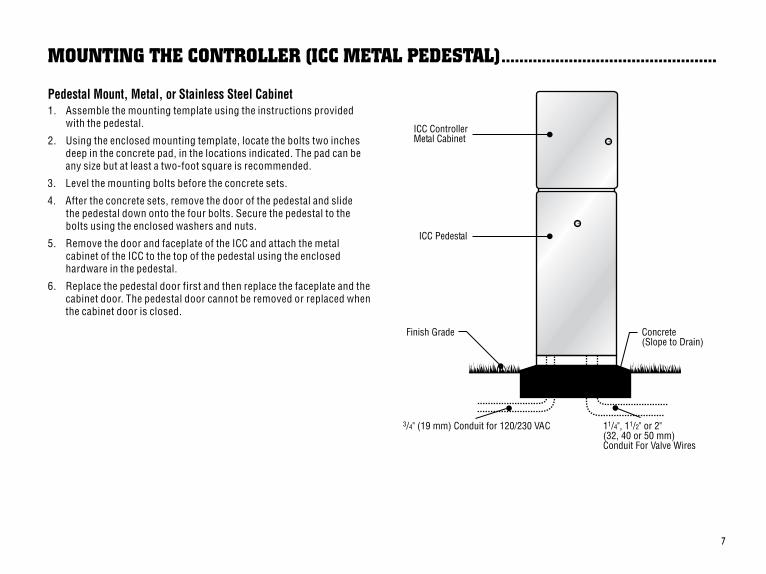
Table of ConTenTs .............................................................................................................
INTRODUCTION AND INSTALLATIONIntroduction................................................................................................................................................................................................... 1
ICC.Components.......................................................................................................................................................................................... 2-3
ICC.Components.–.Wiring.Cabinet................................................................................................................................................................ 4-5
Mounting.the.Controller.to.Wall....................................................................................................................................................................... 6
Mounting.the.Controller.(ICC.Metal.Pedestal).................................................................................................................................................. 7
Mounting.the.Controller.(ICC-800PP/ICC-800SAT)........................................................................................................................................... 8
Connecting.Valves.......................................................................................................................................................................................... 9
Connecting.AC.Power.(ICC-800).................................................................................................................................................................... 10
Connecting.AC.Power.(ICC-801PL.and.ICC-800M/ICC-800SS)........................................................................................................................ 11
Connecting.Station.Modules.......................................................................................................................................................................... 12
Connecting.the.Battery.(Optional).................................................................................................................................................................. 13
Connecting.a.Master.Valve............................................................................................................................................................................ 14
Connecting.a.Pump.Start.Relay..................................................................................................................................................................... 15
Connecting.a.Weather.Sensor.(Not.Included)................................................................................................................................................. 16
Connecting.an.SRR.or.ICR.Remote.Control.(Not.Included)............................................................................................................................. 17
Connecting.the.Hunter.Irrigation.Management.and.Monitoring.System™.(Not.Included).................................................................................. 18
Power.Failures.............................................................................................................................................................................................. 18
CONTROLLER PROGRAMMING AND OPERATIONSprinkler.System.Fundamentals.................................................................................................................................................................... 19
Creating.a.Watering.Schedule........................................................................................................................................................................ 20
How.to.Fill.Out.the.Watering.Schedule........................................................................................................................................................... 20
Watering.Schedule.Form.Example................................................................................................................................................................. 21
Programming.Fundamentals.......................................................................................................................................................................... 22
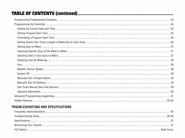
Table of ConTenTs (continued) ........................................................................................Programming.Fundamentals.Examples.......................................................................................................................................................... 23
Programming.the.Controller.......................................................................................................................................................................... 24
Setting.the.Current.Date.and.Time............................................................................................................................................................. 25
Setting.Program.Start.Time....................................................................................................................................................................... 25
Eliminating.a.Program.Start.Time.............................................................................................................................................................. 26
Setting.Station.Run.Times.(Length.of.Watering.for.Each.Area)................................................................................................................... 26
Setting.Days.to.Water............................................................................................................................................................................... 27
Selecting.Specific.Days.of.the.Week.to.Water............................................................................................................................................. 27
Selecting.Odd.or.Even.Days.to.Water......................................................................................................................................................... 27
Selecting.Interval.Watering....................................................................................................................................................................... 28
Run.......................................................................................................................................................................................................... 28
Weather.Sensor.Bypass............................................................................................................................................................................ 28
System.Off............................................................................................................................................................................................... 28
Manually.Run.a.Single.Station................................................................................................................................................................... 29
Manually.Run.All.Stations......................................................................................................................................................................... 29
One.Touch.Manual.Start.and.Advance........................................................................................................................................................ 29
Seasonal.Adjustment................................................................................................................................................................................ 30
Advanced.Programming.Capabilities.............................................................................................................................................................. 31
Hidden.Features....................................................................................................................................................................................... 32-34
TROUBLESHOOTING AND SPECIFICATIONSFrequently.Asked.Questions......................................................................................................................................................................... .34
Troubleshooting.Guide............................................................................................................................................................................. 35-36
Specifications............................................................................................................................................................................................... 37
Winterizing.Your.System............................................................................................................................................................................... 37
FCC.Notice...................................................................................................................................................................................... Back.Cover

�
InTRoDUCTIon .......................................................................................................................
Finally,.there’s.an.affordable,.full-featured.indoor/outdoor.controller.for.commercial.applications.
The.Hunter.ICC.Institutional/Commercial.Controller.is.designed.with.the.needs.of.the.customer.in.mind,.offering.simplified.dial.programming.and.an.impressive.range.of.features.typically.found.in.controllers.that.cost.twice.as.much.
The.ICC.is.very.much.a.professional.grade.product..The.controller’s.large.cabinet.provides.ample.room.for.wiring..And.the.ICC.is.filled.with.essential.features.that.landscapes.demand.like.a.rain.sensor.bypass.circuit,.primary.and.secondary.power.surge.protection,.seasonal.adjustment/water.budgeting,.simultaneous.program.operation,.programmable.pump/master.valve.circuit,.programmable.rain.delay,.cycle.and.soak,.four.independent.programs.with.four.different.day.scheduling.choices.and.eight.start.times.each,.plus.much.more.
The.ICC.is.so.easy.to.use.that.you’ll.need.this.user.guide.very.little.after.installation..If.you.do.have.a.question.about.the.controller,.refer.to.this.booklet.or.to.the.abbreviated.instructions.inside.the.door.
You.can.be.sure.that.you’ve.chosen.with.confidence..The.ICC.is.a.controller.that.does.the.job.efficiently.and.economically.

�
A1 2 3 4
1098
11
13
1415
17
16
1918
12
B
B
C
5
67
ALL STATIONS PROGRAM
ICC ComponenTs ..................................................................................................................

�
This.section.will.give.you.a.brief.overview.of.some.of.the.components.on.the.ICC..Each.item.will.be.discussed.in.further.detail.later,.however.this.section.can.be.helpful.in.getting.acquainted.with.the.different.options.available.
A – LCD Display1. Program Selector.–.Identifies.the.program.in.use.A,.B,.C,.or.D.
2. Station Number.–.Identifies.currently.selected.station.number.
3. Main Display.–.Indicates.various.times,.values,.and..programmed.information.
4. Year –.Arrow.identifies.current.calendar.year.
5. Month.–.Arrow.identifies.current.calendar.month.
6. Day.–.Arrow.identifies.current.calendar.day.
7. Running –.Arrow.indicates.when.watering.is.occurring.
8. Day of the Week.–.Arrow.identifies.days.of.the.week.to.water...You.can.also.select.odd.or.even.and.an.interval.watering.schedule.
9. Odd/Even Watering.–.Arrow.identifies.if.odd.or.even.watering..is.selected.
10. Interval.–.Arrow.identifies.if.interval.watering.has.been.selected.
11. Seasonal Adjust.–.Displays.in.increments.of.10%,.the.percentage.of.seasonal.adjust.that.has.been.selected.
12. Start time.–.Identifies.selected.start.time..(Only.appears.on.LCD.main.display.when.SET PROGRAM START TIMES.is.selected.)
B – Control Buttons and Switches13.. .Button.–.Increases.the.selected.flashing.display.
14.. .Button.–.Decreases.the.selected.flashing.display.
15.. .Button.–.Advances.the.selected.flashing.display.to.the.next.item..Also.to.start.a.manual.cycle.
16.. .Button.–.Returns.the.selected.flashing.display.to.the..previous.item.
17.. .Button.–.Selects.programs.A,.B,.C,.and.D..Also.to.start.a.test.program.cycle.
18. Rain Sensor Switch.–.Allows.user.to.bypass.weather.sensor.if.one.is.installed.
19. and Buttons.–.Used.to.increase.or.decrease.the.seasonal.adjust.option.
A.key.feature.of.the.ICC.is.its.clear,.easy-to-use.dial.design.that..makes.programming.a.snap..All.essential.keypad.functions.are.clearly.marked.to.eliminate.the.confusion.that’s.a.characteristic.of.so.many.other.controllers.
C – Control DialRun.– Normal.dial.position.for.all.controller.automatic.and..manual.operation.
Set Current Date/Time.–.Allows.current.date.and.clock.time..to.be.set.
Set Program Start Times.–.Allows.1.to.8.start.times.to.be.enabled.in.each.program.
Set Station Run Times.–.Allows.user.to.set.each.station.run.time.
Set Days to Water.–.Allows.user.to.select.individual.days.to.water.or.to.select.an.odd,.even,.or.interval.watering.schedule.
Set Pump Operation.–.Allows.user.to.turn.off.pump.or.master.valve.for.specific.stations.
Manual – Single Station.–.Allows.user.to.activate.a.one.time.watering.of.a.single.station.
Manual – All Stations.–.Allows.user.to.activate.a.one.time.watering.of.all.stations.or.a.few.selected.stations.in.a.selected.program.
System Off –.Allows.user.to.discontinue.all.programs.and.stop.all.watering.until.the.dial.is.returned.to.the.RUN position.

�
ICC ComponenTs – WIRIng CabIneT .............................................................................
9V Battery
22 23
21
20
24
25

�
D – Wiring Cabinet20. 9-Volt Battery.–.The.alkaline.battery.keeps.time.during.power.
outages.or.if.the.transformer.is.disconnected..The.user.may.also.program.the.controller.without.AC.power.
21. Reset Button.–.This.button.is.used.to.reset.the.controller.when.installing.or.removing.ICM.modules..It.can.also.be.used.to.restart.the.controller.in.case.of.power.surge.or.display.freezing..No.programmed.data.will.be.lost..
22. Power Module Area.–.Used.to.attach.transformer,.master.valve,.and.other.systems.from.their.source.to.the.controller.
23. Transformer.–.A.transformer.is.installed.in.the.controller.to.route.AC.power.from.the.power.cable.to.the.terminal.strip.area.and.to.ground.the.controller.
24. Junction Box.–.This.box.contains.a.terminal.strip.for.connecting.115.volt.and.230.volt.power.connections.
25. Station Modules.–.With.the.addition.of.4.or.8.station.ICM.modules,.you.have.the.ability.to.run.from.8.to.32.stations.(plastic.cabinet),.and.8.to.48.stations.(metal.and.stainless.steel.cabinet).
Note: Your controller is designed to work only in conjunction with black ICM station modules.

�
moUnTIng THe ConTRolleR To Wall ..........................................................................
ICC ControllerPlastic Cabinet
Screw withScrew Anchor
Cutaway View
Wall Mount for Plastic, Metal, or Stainless Steel CabinetAll.necessary.hardware.is.included.for.most.installations.
1.. Select.a.location.as.close.as.possible.to.a.standard.electrical.outlet.that.is.not.controlled.by.a.light.switch..
2.. Using.the.enclosed.mounting.template,.mark.the.hole.locations.on.the.wall..It.should.be.in.an.easily.accessible.location.at.eye.level..if.possible.
3.. Drill.a.¼".(6.mm).hole.at.each.mark.
4.. Install.screw.anchors.into.holes.if.attaching.controller.to.drywall,.masonry,.or.plaster.walls.
5.. Remove.the.door.and.front.panel.from.the.controller..The.front.door.can.be.removed.by.pulling.out.the.hinge.pin.
6.. Remove.the.protective.plastic.covering.from.around.the.appropriate.mounting.bosses.on.the.back.of.the.controller.cabinet.by.pushing.a.screwdriver.through.them.
7.. Holding.the.controller.cabinet,.line.up.the.holes.in.the.cabinet.with.the.wall.anchors.or.pilot.holes.
8.. Drive.a.screw.through.each.hole.and.secure.snugly.but.do.not..over.tighten.
�
moUnTIng THe ConTRolleR (ICC meTal peDesTal) ................................................
Pedestal Mount, Metal, or Stainless Steel Cabinet1.. Assemble.the.mounting.template.using.the.instructions.provided.
with.the.pedestal.
2.. Using.the.enclosed.mounting.template,.locate.the.bolts.two.inches.deep.in.the.concrete.pad,.in.the.locations.indicated..The.pad.can.be.any.size.but.at.least.a.two-foot.square.is.recommended.
3.. Level.the.mounting.bolts.before.the.concrete.sets.
4.. After.the.concrete.sets,.remove.the.door.of.the.pedestal.and.slide..the.pedestal.down.onto.the.four.bolts..Secure.the.pedestal.to.the.bolts.using.the.enclosed.washers.and.nuts.
5.. Remove.the.door.and.faceplate.of.the.ICC.and.attach.the.metal..cabinet.of.the.ICC.to.the.top.of.the.pedestal.using.the.enclosed.hardware.in.the.pedestal.
6.. Replace.the.pedestal.door.first.and.then.replace.the.faceplate.and.the.cabinet.door..The.pedestal.door.cannot.be.removed.or.replaced.when.the.cabinet.door.is.closed.
Finish.Grad.e.
ICC.Pedest.al.
Concrete.(Slope.to.Drain.)
3./.4.".(19.mm).Conduit.for.120/230..VA.C 1..1/4",.1.1/2".or.2"(32,.40.or.50.mm).Conduit.For..Va.lve.Wires
ICC.Controller.Met.al.Cabine.t.

�
moUnTIng THe ConTRolleR (ICC-800pp/ICC-800saT) ..............................................
Plastic Pedestal Mounting1.. Set.concrete.forms.using.the.installation.instructions.provided..
with.the.controller..Allow.2".of.conduit.above.the.surface.of.the.concrete.pad.
2.. Assemble.the.mounting.template..Twist.one.nut.on.each.of.the.four.J-bolts.and.slide.each.bolt.through.the.template..Put.a.washer.and.nut.on.each.J-bolt.to.secure.it.to.the.template.(allow.2.½".of.thread.protruding.above.each.nut).
3.. Level.the.mounting.template.before.the.concrete.sets.
4.. After.the.concrete.sets,.remove.the.nuts.and.washers.from.the.four.J-bolts.slide.the.pedestal.over.the.bolts..Secure.the.pedestal.to.the.bolts.using.the.enclosed.washers.and.nuts.
Thread.Length.2.50".MinAbove.Concrete
4"
26".Min
12.50"
5.00"
GCBL.Wiring.(Required.For.IMMS)(3".Max.Above.Concrete)
Field.Wiring(3".Max.Above.Concrete)
Template
AC.Power.Wire.S\P(3".Max.Above.Concrete)
21".Min
Concrete.Foundation

�
ConneCTIng ValVes ............................................................................................................
Valve Common Wire
Valve 4
Valve 3
Valve 2
Valve 1
ValveWires
1.. Route.valve.wires.between.control.valve.location.and.controller.
2.. At.valves,.attach.a.common.wire.to.either.solenoid.wire.of.all.valves..This.is.most.commonly.a.white.colored.wire..Attach.a.separate.control.wire.to.the.remaining.wire.of.each.valve..All.wire.splice.connections.should.be.done.using.waterproof.connectors.
3.. Open.hinged.faceplate.on.the.controller.to.access.the.terminal..strip.area.
4.. Route.valve.wires.through.the.conduit.and.attach.conduit.to.the.controller.at.the.large.conduit.opening.on.the.right.side.of.the..bottom.of.the.cabinet..The.conduit.opening.has.a.triple.knockout.to.accommodate.1",.1¼",.or.1½".(25,.32,.or.40.mm).conduit..Each..section.can.be.easily.removed.using.a.knife..Refer.to.the.conduit..sizing.chart.on.page.31 in.the.Frequently.Asked.Questions.section.if.you.are.not.sure.what.size.conduit.will.work.for.your.installation.
5.. Strip.½".(13.mm).of.insulation.from.ends.of.all.wires..Secure.valve.common.wire.to.C.(Common).terminal.on.any.of.the.valve.modules.or.power.module..Then.attach.all.individual.valve.control.wires.to.appropriate.station.terminals.
NOTE: Although it is usually best to connect all field wires prior to powering up the controller, it is not necessary with the ICC. After powering up the controller, attach the common wire to the terminal strip as described above. Then touch each wire to the terminal marked TEST to identify the valve location. Each valve will open electrically when the wire is touched to the TEST terminal. After identifying the valve location, you may then insert the wire into the appropriate terminal. This feature allows you to sequence the valves in the most logical order for the user without damaging the controller by “sparking” the wires.

�0
ConneCTIng aC poWeR (ICC-800) ....................................................................................
It is recommended that a licensed electrician perform the following power installation.
1... Remove.the.cover.from.the.junction.box..
2... Strip.½".off.of.each.wire.
3... For.all.connections,.route.the.wires.through.the.conduit.opening.inside.the.junction.box
4... For.120.volt.connections.twist.the.wires.together.using.wire.nuts.as.shown.in.Figure.1.
5... Cap.any.unused.wires..Replace.faceplate.of.junction.box.and.screw.into.place.
Figure 1 – Junction Box without Terminal Strip (120 Volt)
Green Wire (Ground)
N Blue Wire (Neutral) 120 Black Wire (120 Vo lt)
230 Brown Wire (Use only for 230 VoltConnections )
Green Wire White Wire Black Wire
Figure 2 – Junction Box without Terminal Strip (230 Volt)
Green Wire (Ground)
Green Wire White Wire Brown Wire
N Blue Wire (Neutral) 120 Black Wire (120 Volt)230 Brown Wire (230 Vo lt)Note: Wiring instructions for the ICC-800 SAT are
included in the controller installation instructions supplied with the controller.

��
1.. Remove.the.cover.from.junction.box....
2.. Strip.½".off.of.each.wire.
3.. For.all.connections,.route.the.wires.through.the.conduit.opening.inside.the.junction.box.
4.. For.120.volt.connections.see.Figure.3..For.230.volt.connections.see.Figure.4.
5.. Replace.faceplate.of.junction.box.and.screw.into.place.
ClampGroundingElectrode
Figure 5 Power Module
Green Wire(Ground)
N Blue Wire (Neutral) 120 Black Wire (120 Volt)Figure 3 – Junction Box with Terminal Strip (120 Volt)
Green Wire Blue Wire Black Wire
230 Brown Wire(230 Volt)
Green Wire (Ground)
N Blue Wire (Neutral) Figure 4 – Junction Box with Terminal Strip (230 Volt)
Green Wire Blue Wire Brown Wire
Note: The terminal strip is used in ICC-801PL (International) and ICC-800M controllers.
230 Brown Wire (230 Vo lt)
120 B lack W ire (120 V olt)
Grounding The ICCThe.ICC.is.equipped.with.built-in.electrical.surge.protection..For.this.system.to.function.properly,.the.earth.ground.terminal.on.the.power.module.must.be.connected.to.a.ground.rod.that.is.driven.into.the.earth.
Important:.Use.a.#10.(6.mm).or.#8.(10.mm).bare.wire.to.connect.the.controller.to.the.ground.rod..Use.a.standard.copper.clad,.5/8".(1.6.cm).diameter,.8'.(2.5.m).long.ground.rod.
To.connect.ground.wire:
1.. Feed.the.ground.wire.up.through.the.large.hole.at.the.bottom.of.the.controller.cabinet.(the.same.hole.used.for.the.valve.wires).
2.. Loosen.the.screw.on.the.GND.terminal.on.the.power.module.and.place.the.ground.wire.into.the.terminal..Tighten.the.screw.so.that.the.ground.wire.is.secure.(see.Figure.5).
ConneCTIng aC poWeR (ICC-801pl anD ICC-800m/ICC-800ss) ..............................

��
ConneCTIng sTaTIon moDUles ......................................................................................
The.ICC.controller.is.supplied.with.one.factory-installed.station.module.for.up.to.8.stations..Additional.modules.may.be.added.in.increments.of.4.or.8.stations.to.expand.the.controller’s.station.capability.(maximum.of.32.stations.with.plastic.cabinet.and.maximum.of.48.stations.with.metal,.stainless.steel.cabinet.or.plastic.pedestal)..Additional.modules.are.purchased.separately.
ICM.modules.have.a.Positive-Lock™.feature.that.fastens.the.module.securely.into.the.ICC..Rotating.the.Positive-Lock.lever.makes.it.easy.to.lock.or.unlock.the.module(s)..In.addition,.the.Positive.Lock.feature.will.deactivate.power.to.the.module.in.the.unlocked.position.and.activate.power.to.the.module.when.locked..No.need.to.turn.off.AC.power.to.the.controller.to.remove.or.install.modules..
1.. Rotate.the.Positive-Lock.lever.on.the.module.clockwise.to.the..unlock.position.
2.. The.module.needs.to.be.inserted.into.the.next.sequential.position.in.the.back.of.the.controller..Note:.If.you.are.using.a.4-station.module,.it.must.be.in.the.last.sequential.position.on.the.controller...Example:.For.an.area.that.needs.12.stations,.the.first.module.will.be.an.8-station.and.the.4-station.module.will.be.below.it..Note.that.station.numbers.are.identified.on.the.back.panel,.not.the.individual.modules.
3.. Insert.the.module.into.the.controller’s.expansion.slot.with.the.tab.end.first.(opposite.side.with.the.Positive-Lock.lever).
4.. Push.the.module.into.the.expansion.slot.and.rotate.the.lever.counter-clockwise.(until.the.lever.is.flush.with.the.side.the.module).to.lock.the.module.in.place.
5.. Press.the.reset.button.on.the.back.of.the.front.panel.to.reset.the.microprocessor.to.recognize.additional.modules.
Note: Your ICC controller is designed to work only in conjunction with Black ICM expansion modules.
Positive-Lock™.Lever
��
9V Battery9V Battery9V Battery
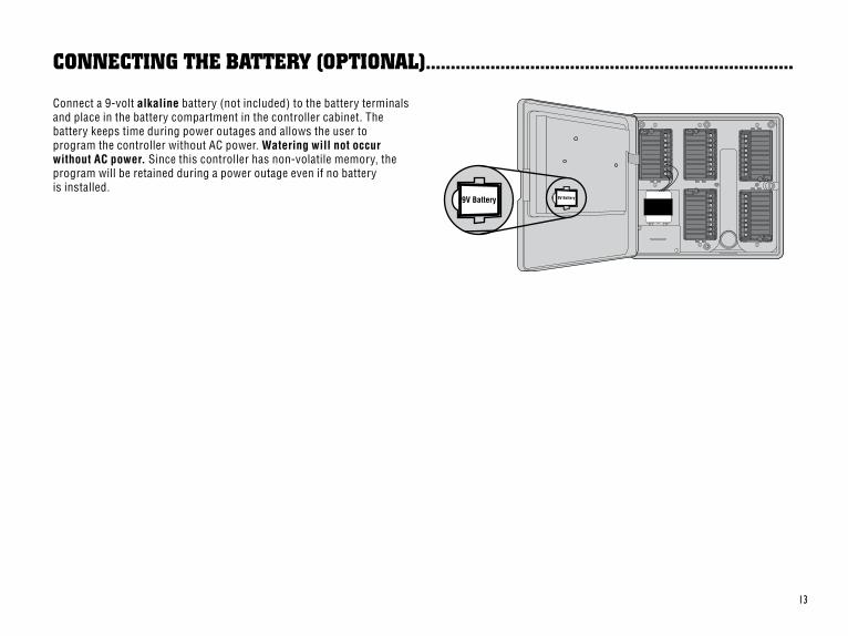
ConneCTIng THe baTTeRY (opTIonal) ..........................................................................
Connect.a.9-volt.alkaline.battery.(not.included).to.the.battery.terminals.and.place.in.the.battery.compartment.in.the.controller.cabinet..The..battery.keeps.time.during.power.outages.and.allows.the.user.to..program.the.controller.without.AC.power..Watering will not occur without AC power..Since.this.controller.has.non-volatile.memory,.the.program.will.be.retained.during.a.power.outage.even.if.no.battery..is.installed.
��
Common Wire Master Va lv e
Master V alve Wire
Power Modul e
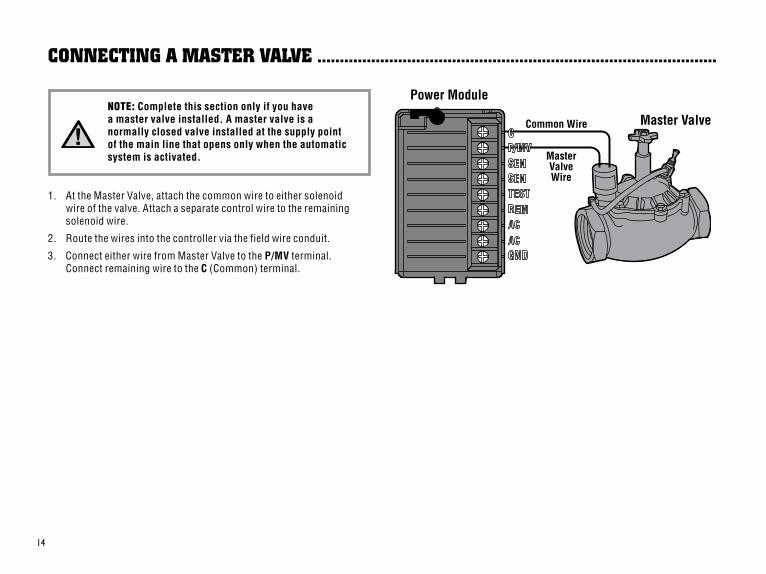
ConneCTIng a masTeR ValVe .........................................................................................
NOTE: Complete this section only if you have a master valve installed. A master valve is a normally closed valve installed at the supply point of the main line that opens only when the automatic system is activated.
1.. At.the.Master.Valve,.attach.the.common.wire.to.either.solenoid..wire.of.the.valve..Attach.a.separate.control.wire.to.the.remaining.solenoid.wire.
2.. Route.the.wires.into.the.controller.via.the.field.wire.conduit.
3.. Connect.either.wire.from.Master.Valve.to.the.P/MV.terminal...Connect.remaining.wire.to.the C (Common).terminal.

��
ConneCTIng a pUmp sTaRT RelaY .................................................................................
Pump Relay Common Wire
Pump Relay Wire
Power Modul e PSR Serie s
Pump Start Relay
To Pum p
15' Minimum (4.5 m)
NOTE: Complete this section only if you have a pump and pump start relay installed. A pump start relay is an electronic device that uses a signal current from the irrigation controller to activate a pump to provide water to your system.
The.controller.should.be.mounted.at.least.15.feet.(4.5.m).away.from..both.the.pump.start.relay.and.the.pump..When.a.pump.is.to.be.operated.by.the.controller,.a.pump.start.relay.must.be.used..Hunter.offers.a.full.range.a.pump.start.relays.for.most.applications.
1.. Route.a.wire.pair.from.the.pump.relay.into.the.controller.housing.
2.. Connect.the.pump.relay.common.wire.to.the.terminal.slot.C.(Common).and.the.remaining.wire.from.the.pump.relay.to.the.P/MV.screw.slot.
Relay.holding.current.draw.must.not.exceed..28.amps.
Do not connect the controller directly to the pump – damage to controller will result.

��
Power Modul e
W eather Sensor
ConneCTIng a WeaTHeR sensoR (noT InClUDeD) ...................................................
A.Hunter.Mini-Clik®.rain.sensor.or.other.type.of.micro-switch.weather.sensor.may.be.connected.to.the.ICC..The.purpose.of.this.sensor.is.to.stop.watering.when.precipitation.is.sufficient..The.sensor.connects.directly.to.the.controller.and.allows.you.to.easily.override.the.sensor.by.using.the.Rain.Sensor.bypass.switch.on.the.controller.
1.. Route.the.wires.from.the.rain.sensor.up.through.the.same.conduit.used.for.valve.wiring.
2.. Remove.the.jumper.from.the.two.SEN.terminals.on.the..power.module.
3.. Connect.one.wire.to.the.SEN.terminal.and.one.to.the.other.SEN..terminal.on.the.power.module
NOTE: If the rain sensor switch is left in the ACTIVE position and no sensor is connected, and the jumper has been removed, the display will read SEN OFF and no irrigation will occur. To eliminate this problem when no sensor is connected, leave the switch in the BYPASS position or install a short jumper wire between the sensor terminals.
For.more.information.on.Mini-Clik.sensors,.visit.Hunter's.Web.site.at.http://www.HunterIndustries.com.or.contact.your.local.dealer.

��
ConneCTIng an sRR oR ICR RemoTe ConTRol (noT InClUDeD)..........................
Controller
Receiver
Outdoor Installation(Temporary Connectionof Receiver Only)
Indoor Installation
1/2" Thread
To Controller
Pre-assembled Assembled
The.ICC.controller.is.shipped.with.a.SmartPort®.wiring.harness,.allowing.for.fast.and.easy.use.of.the.Hunter.SRR.or.ICR.remote.control..The.remote.makes.it.possible.for.contractors.and.end.users.alike.to.operate.a.system.without.having.to.walk.back.and.forth.to.the.controller.
To.utilize.the.SRR/ICR.Remote.Control.System.you.must.install.the.SmartPort.outlet.
1.. Install.a.½".female.threaded.“Tee”.in.the.field.wiring.conduit..approximately.12".below.the.ICC.
2.. Feed.the.red,.white,.and.blue.wires.of.the.harness.through.the.base.of.the.“Tee”.and.into.the.wiring.compartment.as.shown.in.below.
3.. Screw.the.SmartPort.harness.housing.into.the.“Tee”.as.shown.
4.. Access.the.terminal.strip.area.and.attach.the.red.wire.to.the.bottom.most.AC.screw.slot,.attach.the.white.wire.to.the.upper.AC.screw.slot.and.attach.the.blue.wire.to.the.screw.slot.marked.“REM.”
The.SmartPort.is.now.ready.for.remote.control.use..Please.refer.to.the.SRR.or.ICR.owner’s.manual.for.further.information.or.contact.your.local.Hunter.distributor.for.ordering.information.
Power Module
Blue White Red
Smart Port Wiring Harness

��
NOTE: Any extension of the wiring on the SmartPort® may result in an error message in the controller display and possible malfunction of the remote unit due to radio interference. In some situations, lengthening of the harness may work fine, in others it may not work at all (it is site specific). In either case, extending the wiring harness should be done using shielded cable to minimize the possible effects of electrical noise. For easiest installation, order a new Hunter SmartPort shielded cable wiring harness (part #SRR-SCWH) with a full 25 feet of shielded cable.
ConneCTIng an sRR oR ICR RemoTe ConTRol (ConTInUeD) ...............................
ConneCTIng To THe HUnTeR IRRIgaTIon managemenT anD monIToRIng sYsTem™ (noT InClUDeD) .......................................................................With.the.IMMS™,.automatic.irrigation.systems.at.multiple.sites.or.multiple.controllers.at.a.single.site.can.be.programmed.for.functions.that.would.typically.be.handled.directly.at.each.controller..Scheduling.of.days.to.water,.run.times,.start.times,.cycle.and.soak.operations.and.more.can.now.be.done.from.a.single.computer.at.a.desk.miles.away.from.the.actual.installation..In.addition,.scheduled.operation.of.non-irrigation.components.also.in.use.at.these.sites.– e.g.,.lighting.systems.at.athletic.fields,.fountains.at.shopping.centers.– as.well.as.pumps.and.sensors.can.also.be.programmed.and.monitored.from.a.single.central.location..A.key.function.of.the.IMMS.is.its.ability.to.monitor.changing.conditions..With.the.aid.of.such.options.as.flow.sensors,.rain.sensors.and.other.weather-sensing.devices,.the.IMMS.can.receive.reports.on.the.current.condition.at.every.site.it.is.linked.with.and.then.respond.with.the.necessary.adjustments.should.any.of.those.conditions.go.beyond.the.limits.that.have.been.defined..It’s.able.to.team.with.any.or.all.of.the.standard.automatic.controllers.in.the.Hunter.line-up,.from.the.SRC.to.the.Pro-C.to.the.ICC..Plus,.it’s.a.system.that’s.easy.and.affordable.to.upgrade,.making.it.possible.to.accommodate.an.expanding.network.of.controllers..For.more.information.on.the.IMMS.software,.contact.your.local.Hunter.dealer.
The.Hunter.ICC-800.SAT.Field.Satellite.Controllers.are.supplied.with.an.IMMS.Site.or.Controller.Interface.already.prewired.to.the.ICC.Controller..Installation.is.as.simple.as.connecting.AC.power.to.and.communication.wires.to.the.Controller.and.you're.ready.to.operate.the.ICC.from.a.central.computer..Reference.IMMS.Installation.and.Operating.Instructions.for.further.information.
The.ICC-800.PL,.ICC-800M/-800SS.are.all.capable.of.operating.with.IMMS..Separate.Site.or.Controller.Interface.hardware.is.required.(ordered.separately)..For.more.information.on.IMMS,.contact.your.local.Hunter.dealer.or.visit.the.Hunter.website.at.http://www.HunterIndustries.com
Due.to.the.possibility.of.power.failures,.the.controller.has.nonvolatile.memory.to.preserve.the.program.indefinitely..If.no.9-volt.battery.is.installed,.the.controller.will.freeze.time.when.the.power.goes.out.and.resume,.keeping.time.after.power.has.been.restored..If.a.battery.is.installed,.the.9-volt.battery.back.up.will.keep.time.so.the.clock.and.calendar.will.be.intact.for.up.to.three.days..There.is.no.default.program.so.there.will.be.no.surprise.watering.
poWeR faIlURes ...................................................................................................................
��
spRInKleR sYsTem fUnDamenTals .............................................................................V alve 1
Station 1 Station 2
Station 3 Station 6
V alve 2
V alve 3
V alve 5
ICC Controller
Station 5
V alve 4
Station 4
®
®®
®
V alve 6 ®
V alve 7
®
®
®
Station 7
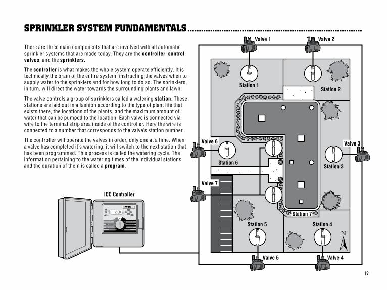
There.are.three.main.components.that.are.involved.with.all.automatic.sprinkler.systems.that.are.made.today..They.are.the.controller,.control valves,.and.the.sprinklers.
The.controller.is.what.makes.the.whole.system.operate.efficiently..It.is.technically.the.brain.of.the.entire.system,.instructing.the.valves.when.to.supply.water.to.the.sprinklers.and.for.how.long.to.do.so..The.sprinklers,.in.turn,.will.direct.the.water.towards.the.surrounding.plants.and.lawn.
The.valve.controls.a.group.of.sprinklers.called.a.watering.station..These.stations.are.laid.out.in.a.fashion.according.to.the.type.of.plant.life.that..exists.there,.the.locations.of.the.plants,.and.the.maximum.amount.of.water.that.can.be.pumped.to.the.location..Each.valve.is.connected.via.wire.to.the.terminal.strip.area.inside.of.the.controller..Here.the.wire.is.connected.to.a.number.that.corresponds.to.the.valve’s.station.number..
The.controller.will.operate.the.valves.in.order,.only.one.at.a.time..When.a.valve.has.completed.it’s.watering;.it.will.switch.to.the.next.station.that.has.been.programmed..This.process.is.called.the.watering.cycle..The.information.pertaining.to.the.watering.times.of.the.individual.stations.and.the.duration.of.them.is.called.a.program.

�0
CReaTIng a WaTeRIng sCHeDUle ...................................................................................
It is usually good to water one or two hours before sunrise. Water pressure will be at optimum levels during the early morning and the water can soak into the roots of the plants while evaporation is minimal. For most plants, watering during mid-day or in the evening may cause plant damage or possibly mildew.
Keep an eye out for evidence of under- or over- watering. Over-watering is most commonly indicated by pools of water that take a long time to soak in or evaporate, while under-watered landscapes will show signs of discoloring and dryness. Make programming changes immediately when evidence is present.
HoW To fIll oUT THe WaTeRIng sCHeDUle ................................................................
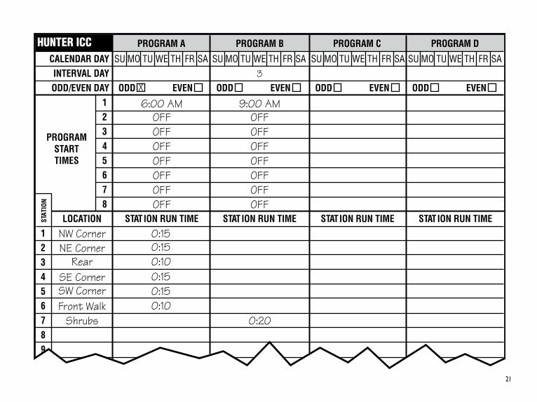
For.most.consumers,.it.is.much.easier.to.plan.your.specific.watering.schedule.onto.paper.before.actually.programming.the.information.into.the.controller..It’s.also.handy.to.have.a.written.record.of.your.programming.information.for.easy.reference.
There.are.some.guidelines.that.should.followed.when.determining.when.and.how.long.to.water..These.factors.are,.the.soil.type,.the.part.of.the.landscape.being.watered,.weather.conditions,.and.the.types.of.sprinklers.being.used..Since.there.are.so.many.different.variables.that.can.determine.your.individual.watering.schedule;.it.is.impossible.to.give.an.exact.schedule.to.follow..However,.we.have.included.some.guidelines.to.help.you.get.started.
Be.sure.to.use.a.pencil.when.filling.out.this.form..By.using.the.included.example.and.the.information.below,.you.should.have.all.the.information.you.need.to.construct.your.personal.water.schedule..There.is.an.example.of.a.completed.form.on.the.following.page.
Station Number and Location.–.Identify.the.station.number,.location,.and.the.type.of.plant.that.is.being.watered.
Watering Day.–.Identify.whether.you.want.to.use.a.calendar.day,.interval,.or.an.odd.or.even.day.schedule..For.a.calendar.day.schedule,.circle.the.day.of.the.week.in.which.watering.is.desired..For.an.interval.
schedule,.indicate.the.desired.interval.number..And.for.an.odd.or.even.day.schedule,.simply.mark.the.corresponding.box.
Program Start Times.–.Indicate.the.time.of.day.that.the.program.will.begin..Each.program.can.have.1.to.8.start.times..However,.one.start.time.can.run.an.entire.program.
Station Run Time.–.Indicate.the.run.time.(1.minute.to.2.hours.or.up.to.12.hours.on.program.D).for.each.station..Write.“OFF”.for.any.station.that.you.do.not.want.to.operate.in.the.program.
Keep.this.schedule.in.a.safe.place.for.quick.reference.later,.rather.than.scrolling.through.program.information.on.the.controller.
��
PROGRAM A
CALENDAR DAY
ODD/EVEN DAY
SU MO TU WE TH FR SA
ODD EVEN
LOCATION
1
STAT
ION
STATION RUN TIME
PROGRAMSTARTTIMES
HUNTER ICC
INTERVAL DAY
PROGRAM B PROGRAM C PROGRAM D
SU MO TU WE TH FR SA
ODD EVEN3
SU MO TU WE TH FR SA
ODD EVEN
SU MO TU WE TH FR SA
ODD EVEN
2345678
123456789
STATION RUN TIME STATION RUN TIME STATION RUN TIME
NW CornerNE Corner
RearSE CornerSW CornerFront Walk
Shrubs
0:150:15
0:150:150:10
0:10
6:00 AMOFFOFFOFFOFF
OFFOFF
OFF
9:00 AMOFFOFFOFFOFF
OFFOFF
OFF
X
0:20

��
pRogRammIng fUnDamenTals......................................................................................
A.watering.program.can.be.created.to.operate.valves.in.numerical.sequence.one.at.a.time..All.that.is.required.to.create.a.watering.program.is.to:.
1.. Select.a.program.(A, B,.or C).by.pressing.the. .button.on.the.controller.(it.is.recommended.to.start.with.Program A)..
2.. Set.a.program.start.time.(only.one.program.start.time.is.required.to.activate.a.watering.program)..
3.. Set.the.run.time.for.each.valve.assigned.to.the.program.and.
4.. Set.the.days.that.you.would.like.the.watering.program.to.run.
For.the.controller.and.its.selected.program.to.operate.automatically,.there.are.three.components.that.must.exist:.When.to.water..(or.Program Start Times),.how.long.to.water.(or.Station Run Times),.what.day.of.the.week.to.water.(or.Days to Water).
We.have.included.an.example.that.will.better.illustrate.the.operation.of.a.program..Let’s.say.you.have.a.program.start.time.set.for.6:00.am..Stations.1.and.2.are.going.to.have.a.run.time.of.15.minutes.and.Station.3.is.set.for.10.minutes..Please.note.that.Stations.4,.5,.etc..have.not.been.included.in.this.program,.we.will.water.them.on.separate.programs.
Going.back.to.our.previous.example,.at.6:00.am.the.controller.will..activate.the.watering.cycle..The.sprinklers.on.Station.1.will.run.for..15.minutes.and.then.shut.off..The.controller.will.automatically.activate.Station.2.sprinklers..These.sprinklers.will.also.run.for.15.minutes.and.then.shut.off..Then,.watering.on.Station.3.will.begin..The.sprinklers.will.turn.on.for.20.minutes.and.shut.off..The.controller.will.run.all.Stations.sequentially.with.Station.6.concluding.the.program.at.7:30.am.
As.shown.in.the.above.example,.only.one.program.start.time.was.required.to.run.the.three.different.stations..The.controller.automatically.moves.to.the.next.station.without.the.need.for.additional.start.times.
We.realize.that.many.consumers.will.have.variations.in.their.plant.watering.needs,.so.at.Hunter.we.equipped.the.ICC.with.four.different.programs:.A,.B,.C,.and.D..These.programs.are.completely.independent.of.each.other.and.give.you.the.ability.to.have.four.coexisting.timers.in.one.controller..The.only.exception.is.program.D,.which.can.be.used.as.a.drip.irrigation.program..Any.station.used.in.program.A,.B,.or.C.can.not.be.used.in.program.D..This.prevents.the.accidental.assignment.of.a.rotor.or.spray.zone.to.program.D,.the.drip.program,.which.could.lead.to.excessive.watering.
Program.D.can.run.concurrently.with.Program.A,.B,.or.C..For.example,.using.more.than.one.program.would.enable.you.to.water.the.lawn.Stations.1,.2,.and.3.on.program.A,.Station.4.to.soak.the.flowers.with.drip.irrigation.on.program.D,.and.Station.5.to.water.the.shrubs.on.program.B..However,.it.is.not.absolutely.necessary.to.use.this.feature..Many.users.prefer.the.simplicity.of.using.one.program.for.all.their.watering.needs..The.additional.programs.are.provided.for.your.convenience.should.the.need.arise.

��
Sprinklers.On.Station.2.begin.to.water.at.6:15..AM.
PROGRAM A
CALENDAR DA Y
ODD/EVEN DA Y
SU.MO.TU.WE.TH. FR.SA.
ODD EVEN
LOCA TION
1
S TA T
IO N
S TAT ION RUN TIME
PROGRAM ST AR T TIMES
HUNTER ICC
INTERV AL DA Y
PROGRAM B
SU.MO.TU.WE.TH. FR.SA.
ODD EVEN 3
2 3 4 5 6 7 8
1 2 3 4 5 6 7 8 9
S TAT ION RUN TIME
NW Corner NE Corner
Rear SE Corner SW Corner Fr ont W alk
Shrubs
0:15 0:15
0:15 0:15 0:10
0:20
6:00 AM OFF OFF OFF OFF
OFF OFF
OFF
9:00 AM OFF OFF OFF OFF
OFF OFF
OFF
X
0:20
12
6
39
12
6
39
12
6
39
Station 1
Station 2
Station 3
®
®
®
®
®
®
Sprinklers.On.Station.1.begin.to.water.at.6:00..AM.
Sprinklers.Off.Station.1.turns.off.at.6:15..AM.
Sprinklers.Off.Station.2.turns.off.at.6:30..AM.
Sprinklers.On.Station.3.begin.to.water.at.6:30..AM.
Sprinklers.Off.Station.3.turns.off.at.6:50..AM.
1st.Program.Start.Time.at.6:00.AM.
Cycle.Ends.at.7:30.AM...
(After.Station.6..Finishes.Watering).
Automaticallyadvances.to.next.station.
Automaticallyadvances.to.next.station.
15 min.
15 min.
20 min.
Total Cycle of Program A = 50 minutes
Program A
pRogRammIng fUnDamenTals example ..................................................................

��
pRogRammIng THe ConTRolleR ...................................................................................
Two.key.features.of.the.ICC.that.make.programming.a.snap.are.its.clear,.easy-to-read.LCD.display.and.its.easy-to-use.dial.design.
The.ICC.display.shows.time.and.day.when.the.controller.is.idle...The.display.changes.when.the.dial.is.rotated.to.indicate.the.specific.programming.information.to.enter..When.programming,.the.flashing.portion.of.the.display.can.be.changed.by.pressing.the. .or. .buttons..To.change.something.that.is.not.flashing,.press. .or. .until.desired.field.is.flashing.
The.ICC.controller.offers.maximum.scheduling.flexibility.including..four.programs,.each.with.up.to.8.daily.start.times,.permitting.plants..with.different.watering.requirements.to.be.separated.on.different.day.schedules..Multiple.start.times.permit.morning,.afternoon.and.evening.watering,.perfect.for.the.establishment.of.new.lawns.and.thirsty.annual.flowers..A.built.in.365-day.calendar.clock.accommodates.odd/even.watering.restrictions.without.requiring.monthly.reprogramming...Or,.just.simply.designate.the.days.of.the.week.you.want.to.water.or.use.the.convenient.day.interval.watering..The.ICC.makes.it.easy.
NOTE: A basic programming rule is that whatever symbol or character is flashing will be the item programmed. For instance, if the hour is flashing when setting the time, the hour can be changed or programmed. For illustration purposes, flashing characters are in GRAY type. Setting The Current Date And Time
To.activate.a.program.in.your.controller,.you.must.enter.the.following.information:
1.. Set.current.day.and.time.–turn.dial.to.SET CURRENT DATE/TIME.
2.. Set.what.time.of.day.you.would.like.the.program.to.start.–.turn.dial.to.SET PROGRAM START TIMES.
3.. Set.how.long.each.valve.will.water.–turn.dial.to..SET STATION RUN TIMES.
4.. Set.the.day(s).you.would.like.the.program.to.water.–turn.dial.to.SET DAYS TO WATER.
NOTE: All stations operate in numerical order. Only one program start time is required to activate all stations in the watering program.
ALL STATIONS PROGRAM

��
Setting The Current Date And Time1.. Turn.the.dial.to.the.SET
CURRENT DATE/TIME.position.
2.. The.current.year.will.be.flashing.in.the.display..Use.the. .and.
.buttons.to.change.the.year..After.setting.the.correct.year,.push.the. button.to.proceed..to.setting.the.month.
3.. The.month.and.day.will.be.in.the.display..The.month.will.be..flashing..Use.the. .and. .buttons.to.change.the.month..Press.the. button.to.proceed.to.setting.the.day.
4.. The.day.will.be.flashing:.Use.the..and. .buttons.to.change.the.
day.of.the.month..(The.day..of.the.week.is.automatically..indicated.by.an.arrow.in.the..bottom.of.the.display.pointing..to.the.day.).Press.the. .button.to.proceed.to.setting.the.time..
5.. The.time.will.be.displayed:.Use.the. .and. .buttons.to.select.AM,.PM,.or.24.hr..Press.the. .button.to.move.to.hours..Hours.will.be.flashing..Use.the. .and.
.buttons.to.change.the.hour.shown.on.the.display..Press.the.
.button.to.move.onto.the.minutes..Minutes.will.be..flashing..Use.the. .and. .buttons.to.change.the.minutes.shown..in.the.display..The.date,.day,.and.time.have.now.been.set.
PM
SET CURRENT DA TE /T IM E SET PROGRAM
START TIMES
PM
START TIME
Setting Program Start Time1.. Turn.the.dial.to.the.SET
PROGRAM START TIMES.position.
2.. The.factory.preset.is.set.on.program.A..If.necessary.you.can.select.program.B,.C,.or.D.by.pressing.the. .button.
3.. Use.the. .and. .buttons.to.change.the.start.time..(Advances.in.15-minute..increments.)
4.. Press.the. button.to.select.the.next.start.time,.or. .for.the.next.program.
NOTE: Regardless of the order in which the start times are entered, the ICC will always arrange the start times in chronological order when the dial is moved off the SET PROGRAM START TIMES position.
One start time will activate stations sequentially in that program one at a time. Multiple start times in a program can be used for separate morning, afternoon, or evening watering cycles. Do not enter a start time for each station.

��
pRogRammIng THe ConTRolleR (continued) ..............................................................
SET PROGRAMSTART TIMES
PM
START TIME
Eliminating A Program Start TimeWith.the.dial.set.to.the.SET PROGRAM START TIMES..position,.push.the. .and. ..buttons.until.you.reach.12:00.am.(Midnight)..From.this.position.push.the. .button.once.to.reach.the.OFF.position.
NOTE: If a program has all eight start times turned off, then that program is off (all other program details are retained). Because there are no start times, there will be no watering with that program. This is a convenient way to stop watering on one program only without turning the dial to the off position.
SET STATIONRUN TIMES
START TIME
START TIME
Setting Station Run Times (Length of Watering for Each Area)1.. Turn.the.dial.to.the.SET
STATION RUN TIMES.position.
2.. The.display.will.show.the.last.program.selected.(A,.B,.C,.or.D)..You.can.switch.to.another.program.by.pressing..the. .button.
3.. Use.the. .and. .buttons.to.change.the.station.run.time.on.the.display.
4.. Press.the. .button.to.advance.to.the.next.station.
5.. Repeat.steps.4.and.5.for.each.station.
6.. You.may.set.station.run.times.from.1.minute.to.2.hours..If.the.station.is.assigned.program.D,.the.run.time.can.be.set.for.up.to.12.hours.
7.. You.can.move.between.programs.while.staying.on.the.same.station..However,.it.is.recommended.that.one.program.is.completed.before.going.on.to.the.next.program..Jumping.between.programs.can.be.confusing.and.may.result.in.program.errors.

��
NOTE: If a station is assigned a run time on program A, B, or C, then that station cannot be assigned to Program D. If this is attempted, the word USED will appear in the display. Likewise, a station with a run time on Program D cannot be assigned to program A, B, or C. This is to prevent the accidental assignment of a rotor or spray zone to the D program which is normally reserved for drip applications.
SET DAYSWATER
Setting Days To Water1.. Turn.the.dial.to.the.SET DAYS
TO WATER.position.
2.. The.display.will.show.the.last.program.selected.(A,.B,.C,.or.D).the.station.number.selected,.and.the.run.time.for.that..station.will.be.flashing..You.can.switch.to.another.program.by.pressing.the. .button.
3.. The.controller.displays..currently.programmed.active.day.schedule.information..This.dial.position.provides.four.different.water.day.options:.choose.to.water.on.specific.days.of.the.week,.you.can.choose.interval.watering,.or.choose.to.water.on.odd.days.or.even.days..Each.program.can.only.operate.using.one.type.of.water.day.option.
Selecting Specific Days of the Week to Water1.. With.the.arrow.cursor.on.a.specific.day.(the.cursor.always.starts.
with.Sunday),.press.the. .button.to.activate.a.particular.day.of.the.week.to.water..Press.the. .button.to.cancel.watering.for.that.day..After.pressing.a.button.the.cursor.automatically.advances.to.the..next.day.
2.. Repeat.step.1.until.desired.days.have.been.selected..The.selected.days.arrows.will.show.on.the.display.to.indicate.their.status.as.ON..The.last.solid.arrow.is.the.last.day.of.watering.for.that.program.
Selecting Odd or Even Days to WaterThis.feature.uses.a.numbered.day.of.the.month.for.watering.instead.of.specific.days.of.the.week.(Odd.days.1st,.3rd,.5th,.etc.;.Even.days.2nd,.4th,.6th,.etc.).
1.. Press.the. .button.until.the.arrow.cursor.is.above.either.EVEN.or.ODD.on.the.display.
2.. Press.the. .button.to.select.or.the. .button.to.cancel.either.Odd Days.or.Even Days..The.previous.selected.days.of.the.week.will.revert.to.active.if.Odd Days.or.Even Days.is.cancelled.
NOTE: The 31st of any month and February 29th are always “off” days if Odd watering is selected.

��
pRogRammIng THe ConTRolleR (continued) ..............................................................
Selecting Interval WateringThis.feature.is.convenient.if.you.want.to.have.a.more.consistent.watering.schedule.without.having.to.worry.about.the.day.of.the.week.or.the.date..The.interval.you.select.is.the.amount.of.days.between.watering..The.days.remaining.indicates.how.many.days.until.the.next.watering..For.example.if.you.select.an.interval.of.4.with.1.days.remaining,.watering.will.begin.tomorrow.at.the.scheduled.time..
1.. Turn.the.dial.to.SET DAYS TO WATER the.triangle.above.Sunday.should.be.flashing.
2.. Use.the. .button.and.move.the.flashing.arrow.cursor.above.the.INTERVAL..designator.
3.. Press.the. .button..The.display.will.now.show.two.numbers,.the.interval.and.the.days.remaining.in.the.interval.
4.. The.number.of.days.between.waterings,.or.the.interval.will.be.flashing..Use.the. .and. .buttons.to.select.the.number.of..days.desired.between.waterings.
5.. Press.the. .button..The.days.remaining.in.the.interval.are.now.flashing..Use.the. .and. .buttons.to.select.the.number.of.days.until.the.next.desired.watering..One.day.remaining.means.it.will.water.the.next.day..
After.programming,.set.dial.to.RUN.to.enable.automatic.execution.of.all.selected.programs.and.start.times.
INTERVAL DAYS REMAINING
RUN
ACTIVE BYPASS
RunAfter.programming.is.complete,..turn.the.dial.to.RUN.to.enable..automatic.execution.of.all.selected.programs.and.start.times..Watering will not occur unless dial is in the RUN position.
Weather Sensor BypassWith.this.built-in.feature,.there.is.no.need.for.an.additional.manual.bypass.switch.when.using.rain.sensors.(the.ICC.works.with.the.Hunter.Mini-Clik®,.plus.some.other.rain,.wind,.and.freeze.sensors.on.the.market.today)..If.the.system.is.preventing.system.operation.(or.no.sensor.is.installed.and.the.switch.is.in.the.ACTIVE position),.SEN OFF.will.be.displayed..Simply.move.the.switch.to.BYPASS and.the.weather.sensor.will.be.bypassed..This.allows.you.to.use.the.system.
System OffValves.currently.watering.will.be.shut.off.after.the.dial.is.turned.to.the.SYSTEM OFF.position.for.two.seconds..All.active.programs.are.discontinued.and.watering.is.stopped..To.return.controller.to.normal.automatic.operation,..simply.return.dial.to.RUN.position.
SYSTEM OFF
RUN

��
MANUAL SINGLESTATION
Manually Run a Single Station1.. Turn.the.dial.to.the.MANUAL-
SINGLE STATION.position.
2.. Station.run.time.will.flash.in.the.display..Use.the. .button.to.move.to.the.desired.station..You.may.then.use.the. .and. .buttons.to.select.the.amount.of.time.for.a.station..to.water.
3.. Turn.the.dial.to.the.RUN..position.to.run.the.station.(only.the.designated.station.will.water,.then.controller.will.return.to.automatic.mode.with.no.change.in.the.previously.set.program).
MANUAL ALLSTATION
Manually Run All Stations1.. Turn.the.dial.to.MANUAL-ALL
STATIONS.
2.. You.can.select.program..A,.B,.C,.or.D.by.pressing.the..
.button.
3.. Press.the. button.until.desired.starting.station.is.displayed.
4.. Station.run.time.will.flash.in.the.display..Use.the. .and. .buttons.to.select.the.amount.of.run.time.for.the.station.to.water..if.different.from.the.run.time.displayed.
One Touch Manual Start and AdvanceYou.can.also.activate.all.stations.to.water.without.using.the.dial.
1.. Hold.down.the. .button.for.2.seconds...
2.. This.feature.automatically.defaults.to.program.A..You.can.select.program.B,.C.or.D.by.pressing.the. .button.
3.. The.station.number.will.be.flashing..Press.the. .or. .button.to.scroll.through.the.stations.and.use.the. .and. .buttons.to.adjust.the.station.run.times..(If.no.buttons.are.pressed.during.step.2.or.3,.the.controller.will.automatically.begin.program.A.)
4.. Press.the. button.to.scroll.to.the.station.you.wish.to.begin.with..After.a.2.second.pause,.the.program.will.begin.
This.feature.is.great.for.a.quick.cycle.when.extra.watering.is.needed.or.if.you.would.like.to.scroll.through.the.stations.to.inspect.your.system.
5.. Use.the. .button.to.move.to.the.next.station.
6.. Repeat.steps.3.and.4.to.customize.each.station.if.desired.
7.. Press.the. .button.until.desired.starting.station.is.displayed.
8.. Return.the.dial.to.RUN (custom.program.will.water.the.entire.program.beginning.with.the.station.number.last.left.in.the.display,.then.controller.will.return.to.automatic.mode.with.no.change.in.the.previously.set.program).
NOTE: The station that is on the display when you turn the dial to RUN will be the first station to run. The controller will then proceed to water in sequential order only. It will not water previous stations. Example: If you turn the dial to RUN with the display reading station 3, the controller will water Stations 3 through 9 in the program, but not return to Stations 1 and 2.

�0
Seasonal AdjustmentSeasonal.Adjust.is.used.to.make.global.run.time.changes.without..reprogramming.the.entire.controller..This.feature.is.perfect.for..making.small.changes.that.are.necessary.as.the.weather.changes..without.reprogramming.the.entire.controller..For.instance,.hotter.times.of.the.year.may.require.a.bit.more.water..Seasonal.adjust.can.be.increased.so.that.the.stations.will.run.longer.than.the.programmed.time..Conversely,.as.Fall.approaches,.the.seasonal.adjust.can.be.reduced.to.allow.for.short.watering.durations.
To.use.the.seasonal.adjust,.simply.press.the. or. seasonal..adjust.buttons.to.set.the.percentage.desired..The.watering.run.time.can.be.adjusted.from.10%.to.150%.of.original.program..The.season.adjust.can.be.changed.at.any.time.regardless.of.the.programming.dial.position..To.view.the.new.adjusted.run.time,.simply.turn.the.rotary.dial.to.the.SET RUN TIMES.position,.the.displayed.run.time.will.be.updated..accordingly.as.the.seasonal.adjustment.is.made..The.seasonal.adjustment.will.affect.all.station.run.times.programmed
NOTE: The controller should always be initially programmed in the 100% position.
pRogRammIng THe ConTRolleR (continued) ..............................................................

��
SET PUMPOPERATION
PUMP
PUMP
SYSTEM OFF
There.are.four.advanced.features.available.to.customize.the.ICC.to.more.complex.watering.requirements..Two.of.these.features.are.“hidden”.to.make.accidentally.programming.them.nearly.impossible.
Set Pump/Master Valve OperationThe.default.is.for.all.stations.to.have.the.master.valve/pump.start.circuit.ON..The.master.valve/pump.start.can.be.set.ON.or.OFF.by.station,..regardless.of.which.program.the.station.is.assigned..This.feature.may..be.utilized.on.systems.where.it.is.desirable.for.a.booster.pump.not.to.operate.with.certain.zones.
To.program.pump.operation:
1.. Turn.the.dial.to.SET PUMP OPERATION.position.
2.. Press.the. .or. .buttons.to.toggle.the.master.valve/pump.start.ON.or.OFF.for.the..specific.station.
3.. Press.the. .button.to.advance.to.the.next.station.
4.. Repeat.steps.2.and.3.for.all.necessary.stations.
Programmable Rain OffThis.feature.permits.the.user.to.stop.all.programmed.waterings.for.a.designated.period.from.1.to.7.days..At.the.end.of.the.Rain.Delay,.the.controller.will.resume.normal.automatic.operation.
1.. Turn.the.dial.to.the.SYSTEM OFF.position.
2.. Press.the. .button.and.a.1.will.be.displayed.and.the.DAYS.icon.will.illuminate..The.1.will.be.blinking.at.this.point.
3.. Press. .as.many.times.as.needed.to.set.the.number.of.days.off.desired.(up.to.7).
4.. To.validate.this.setting.(and.to.make.sure.the.controller.comes.back.on.after.the.period.is.over),.turn.the.dial.back.to.the.RUN.position.at.which.time,.OFF,.a.number.and.the.DAYS.icon.all.remain.on.
5.. Leave.the.dial.in.the.RUN position.
NOTE: The days off remaining will decrease at midnight of each day. When it goes to zero, the display will show the normal time of day and normal irrigation will resume at the next scheduled start time.
aDVanCeD pRogRammIng CapabIlITIes ......................................................................

��
RUN
CYCLE
SET STATIONRUN TIMES
SOAK
NOTE: The hidden features described below can only be entered by starting with the dial in the RUN position and holding down various buttons while the knob is turned to various setup positions. This makes it virtually impossible for someone to stumble onto these features.
Cycle and SoakThe.Cycle.and.Soak.feature.allows.the.user.to.split.each.station’s.run.time.into.more.usable,.shorter.duration.waterings..This.feature.is.particularly.applicable.for.slopes.and.tight.soil.(such.as.clay).because.Cycle.and.Soak.will.help.prevent.excessive.run.off..You.should.enter.the.Cycle.time.as.a.fraction.of.the.station’s.watering.time.and.the.Soak.time.as.the.minimum.soak.required.before.watering.the.next.portion..The.total.number.of.cycles.is.determined.by.taking.the.total.programmed.station.run.time.and.dividing.it.by.the.Cycle.time.
For.example:.Suppose.Station.1.required.20.minutes.worth.of.water.but.after.only.5.minutes,.runoff.occurred..However,.after.10.minutes.all.the.water.was.absorbed..The.solution.would.be.to.program.20.minutes.for.the.Station.Run.Time,.5.minutes.for.the.Cycle.time,.and.10.minutes.for.the.Soak..Station.1.will.then.water.for.5.minutes.and.then.the.rest.of.the.stations.in.the.program.will.water..After.all.the.other.stations.have.watered.the.controller.will.check.to.see.if.Station.1.had.soaked.for.at.least.10.minutes..If.it.had,.then.Station.1.will.water.for.another.5.minutes..This.process.would.continue.to.repeat.itself.until.Station.1.watered.4.times.for.5.minutes.each.time,.a.total.of.20.minutes.
1.. Start.with.the.dial.in.the.RUN.position.
2. Press and hold the. .button.down.while.turning.the.dial.to.the.SET STATION RUN TIMES position.
3.. Release.the. .button..At.this.point,.the.display.will.show.the.station.number,.the.cycle.time.will.be.blinking..The.CYCLE.and.soak.icons.will.also.be.lit.
4.. Press.the. .or. .buttons.to.increase.or.decrease.the.cycle.time.from.1.to.60.minutes.in..1.minute.increments.
5.. Press.the. .key.to.advance..to.the.next.station.and.its..cycle.time.
6.. Pressing.the. .key.will..display.the.previous.station.and.its.cycle.time.
7.. Return.the.Dial.to.the.RUN.position.after.setting.all.the.cycle.and.soak.times.
HIDDen feaTURes .................................................................................................................

��
SET STATIONRUN TIMES
RUN
DELAY
Setting the Soak TimesIt.is.only.necessary.to.set.a.SOAK.time.if.the.accumulated.CYCLE times.on.any.single.program.will.not.provide.an.adequate.soak.time..For..instance,.if.the.sum.of.the.cycle.times.for.all.stations.in.a.program..exceeds.10.minutes.and.each.station.will.require.no.more.than.20..minutes.of.soak.time,.then.the.accumulated.cycle.times.are.sufficient.and.no.soak.time.will.need.to.be.programmed..However,.if.the.necessary.soak.time.did.exceed.the.10.minutes,.then.a.soak.time.must.be.entered.for.those.stations.requiring.a.longer.soak.between.waterings..The.soak.time.default.is.10.minutes.
Pressing.the. .button.at.any.time.while.in.the.cycle.time.setup.will.allow.the.user.to.enter.the.soak.time.setup.for.that.station..Pressing.
.again.will.go.back.to.the.cycle.time.setup..The.soak.time.works.identically.to.the.cycle.time.setup.except.that.the.SOAK.icon.will.be.on.as.opposed.to.the.CYCLE.icon.
NOTE: If the dial is moved from the SET STATION RUN TIMES position, then the entire sequence of going back to RUN and holding the key down must be repeated to reenter the cycle and soak setup. The cycle and soak feature is a station dependent function and will be used whenever the station operates regardless of which program or programs the station is assigned.
1.. Start.with.the.dial.in.the.RUN.position.
2.. Press.and.hold.the. .button.down.while.turning.the.dial.to.the.SET STATION RUN TIMES.position.
3.. Release.the. .button..At.this.point.the.display.will.show.a.delay.time.for.all.stations.in.seconds,.which.will.be.blinking..The.DELAY.icon.shall.also.be.lit.at.this.time.
4.. The.display.will.show.“SEC”..Use.the. .and. .buttons.to.increase.or.decrease.the.delay.time.between.0.and.10.minutes.in.1.second.increments.
5.. Pressing.either.the. .button.or.the. button.will.allow.for.programming.a.longer.delay.between.stations..The.display.will.show.the.delay.in.minutes.
6.. Press.the. .and. .buttons.to.increase.or.decrease.the.delay.time.from.0.to.10.hours.in.5.minute.increments.
7.. Return.the.dial.to.the.RUN position. DELAY
Programmable Delay Between StationsThis.feature.allows.the.user.to.insert.a.delay.between.when.one.station.turns.off.and.the.next.station.turns.on..This.is.very.helpful.on.systems.with.slow.closing.valves.or.on.pump.systems.that.are.operating.near.maximum.flow.or.have.slow.well.recovery.

��
What Size Field Wiring Conduit Should I Use?Locate.the.size.conduit.across.the.top.and.the.wire.size.along.the.side..Where.the.two.intersect.on.the.table.tells.you.approximately.how.many.wires.will.fill.the.conduit..Example:.49.wires.of.18.AWG.will.fit.in.1½".conduit.
Clearing Controller’s Memory / Resetting ControllerIf.you.feel.that.you.have.misprogrammed.the.controller,.there.is.a..process.that.will.reset.the.memory.to.factory.defaults.and.erase.all..programs.and.data.that.have.been.entered.into.the.controller..
1.. Turn.the.dial.to.the.RUN.position.
2.. Remove.battery.
3.. Hold.down.the. .button,.the. .button,.and.the. .button.simultaneously.
4.. While.holding.down.the.three.buttons,.press.and.release.the.reset.button.on.the.back.of.the.front.panel,.then.release.the.three.buttons..
Hold.all.buttons.and.reset.until.display.flashes.12:00..All.the.memory.has.been.cleared.and.the.controller.may.be.reprogrammed.
Hunter Quick Check™Irrigation.professionals.are.continuously.looking.for.ways.to.more.efficiently.and.effectively.diagnose.programs.in.the.field..Instead.of.having.to.physically.check.each.field.wiring.circuit.for.potential.problems,.the.user.can.run.the.Hunter.Quick.Check™.circuit.test.procedure..This.circuit.
NOTE: The Master Valve/Pump Start circuit will operate during the first 20 seconds of any programmed delay to aid in the closing of the valve and to avoid unnecessary cycling of the pump. It is recommended that a pressure relief valve be installed on the system should this 20 second delay be too long for a particular system. Consult your pump contractor or supplier for details.
diagnostic.procedure.is.very.beneficial.because.of.its.ability.to.aid.in.quickly.identifying.“shorts”.commonly.caused.by.faulty.solenoids.or.when.a.bare.common.wire.touches.a.bare.station.control.wire.
To.initiate.the.Hunter.Quick.Check.test.procedure;.Press.the. ,. ,. ,.buttons..In.the.standby.mode,.the.LCD.will.display.all.segments.(helpful.when.troubleshooting.display.problems)..Press.the. .button.to.begin.the.Quick.Check.test.procedure..Within.seconds,.the.system.searches.all.stations.in.an.effort.to.detect.a.high.current.path.through.the.station.terminals..When.a.field.wiring.short.is.detected,.an.ERR.symbol.preceded.by.the.station.number.will.momentarily.flash.on.the.controller.LCD.display..After.the.Hunter.Quick.Check.completes.running.this.circuit.diagnostic.procedure,.the.controller.returns.to.the.automatic.watering.mode.
Test ProgramThe.ICC.allows.the.user.a.simplified.method.for.running.a.test.program..This.feature.operates.each.station.in.numerical.sequence,.from.the..lowest.to.the.highest..You.can.start.with.any.station..This.is.a.great.feature.to.check.the.operation.of.your.irrigation.system.
To.initiate.the.test.program:
1..Press.and.hold.the. .button..The.station.number.will.be.flashing.
2..Press.the. .or. .button.to.scroll.to.the.station.you.would.like.the.test.program.to.start.with..Use.the. .or. .button.to.set.the.run.time.up.to.15.minutes..The.run.time.needs.to.be.entered.only.once.
3..After.a.2.second.pause,.the.test.program.will.begin.
DELAY
fReqUenTlY asKeD qUesTIons ......................................................................................CONDUIT SIZES
Wire Size 1" (25 mm) 1¼" (32 mm) 1½" (40 mm)18 AWG 20 34 4916 AWG 16 30 4214 AWG 10 18 2512 AWG 7 15 20
HIDDen feaTURes (continued) ............................................................................................

��
TRoUblesHooTIng gUIDe ..................................................................................................
PROBLEM CAUSES SOLUTIONS
The controller repeats itself or continu-ously watering even when it should not be on/controller cycles over and over.
Too.many.start.times.(user.programming.error).
Only.one.start.time.per.active.program.is.required..Refer.to."Setting Program Start Times".on.page.24.
There is no display. Check.AC.power.wiring. Correct.any.errors.
The display reads “ERR”. Electrical.noise.is.entering.the.system. Check.the.SmartPort®.wiring.harness..If.the.wires.were.extended.then.they.will.need.to.be.replaced.with.shielded.cable..Contact.your.local.distributor.for.information.on.shielded.cable..
The display reads “P ERR”. There.is.a.ground.fault.in.the.wire.to.the.pump.start.or.master.valve.
Check.the.master.valve.or.pump.start.wire.for.continuity..Replace.or.repair.the.broken.wire..Check.that.all.wire.connections.are.good.and.water.tight.
The display reads a station number and ERR, such as “2 ERR”.
There.is.a.ground.fault.in.the.wire.leading.to.that.station.
Check.the.station.wire.for.continuity..Replace.or.repair.broken.wire..Check.that.all.wire.connections.are.good.and.water.tight.
The display reads “NO AC”. There.is.no.AC.power.present.to.operate.controller/valves.
Check.to.see.if.the.transformer.is.properly.installed.
The display reads “SEN OFF”. The.rain.sensor.is.interrupting.irrigation.or.not.installed.
Slide.the.Rain.Sensor.switch.on.front.panel.to.the.bypass.position.to.bypass.rain.sensor.circuit.

��
PROBLEM CAUSES SOLUTIONS
The controller does not start automatically.
Possible.programming.error. Check.to.make.sure.start.time.is.entered..correctly.(note.AM/PM.setting.as.well)..Check.to.make.sure.watering.day.is.active..
Rain sensor will not shut off system. Incorrect.sensor.type.wired.directly.into.sen-sor.circuit..(Jumper.installed)
Make.sure.sensor.is.microswitch.type.such.as.Mini-Clik®.
The controller recognizes 48 stations all the time.
Microprocessor.requires.reset. Make.sure.AC.power.is.connected..Reset.controller.using.method.described.on..page.34.
The controller does not respond to all the stations. Example, the controller has 24 stations but the display will only go to 16 stations.
Controller.does.not.recognize.modules. Turn.off.the.power.to.the.controller.and.re-move.the.battery..Check.all.module.connec-tions.to.the.controller..Power.the.controller.back.up..The.microprocessor.will.recognize.all.modules.
The controller is only recognizing eight stations when multiple modules are installed and/or there are not enough start times for all stations.
The.dial.is.in.the.START TIMES position.and.not.the.STATION RUN TIMES.position.(see.page.26).
Be.sure.dial.is.in.correct.position..Total.number.of.stations.can.be.easily.checked.by.placing.dial.in.SET STATION RUN TIMES.position.and.pressing.the.back.arrow.
Controller has display but will not activate zone valves.
Primary.power.to.controller.incorrectly.wired..Controller.receiving.voltage.too.low.for.valve.operation.
Check.and.correct.110.or.220.volt..connection..110.volt.may.be.incorrectly.wired.as.220.volt.
TRoUblesHooTIng gUIDe (continued) .............................................................................

��
speCIfICaTIons .....................................................................................................................
Operating Specifications• Station.Run.Time:.1.minute.to.2.hours.(in.1-minute.increments)..
on.programs.A,.B,.and.C..Up.to.12.hours.on.program.D..The.longer.run.time.on.program.D.is.primarily.to.accommodate.drip.irrigation.applications.
• Start.Times:.8.per.day,.per.program,.for.up.to.32.daily.starts.
• Watering.Schedule:.7-day.calendar,.interval.watering.up.to.a.31-day.interval.or.true.odd.or.even.day.programming,.made.possible.by.the.365-day.clock/calendar.
Electrical Specifications• Transformer.Input:.120.VAC,.60Hz.(230.VAC,.50/60.Hz.International.Use)
• Transformer.Output:.25.VAC,.1.5.amp
• Station.Output:.24.VAC,..56.amps.per.station
In.regions.within.the.country.where.the.frost.level.falls.below.the.depth.of.the.installed.piping,.it.is.common.for.these.systems.to.be.'winterized"..Several.methods.can.be.used.to.drain.the.water.from.the.system..If.the.blow.out.method.is.used.it.is.recommended.that.a.qualified.licensed.contractor.perform.this.type.of.winterization.
WARNING! WEAR ANSI APPROVED SAFETY EYE PROTECTION ! Extreme.care.must.always.be.taken.when.blowing.out.the.system.with.compressed.air..Compressed.air.can.cause.serious.injury,.including.serious.eye.injury.from.flying.debris..Always.wear.ANSI.approved.safety.eye.protection.and.do.not.stand.over.any.irrigation.components.(pipes,.sprinklers,.and.valves).during.blow.out..SERIOUS PERSONAL INJURY MAY RESULT IF YOU DO NOT PROCEED AS RECOMMENDED.
• Maximum.Output:.24VAC,.1.4.amps.(includes.Master.Valve.Circuit)
• Battery.Backup:.9-volt.alkaline.battery.(not.included).used.only.for.time.keeping.during.power.outages,.the.nonvolatile.memory..maintains.program.information
DimensionsPlastic Cabinet Metal Cabinet Metal Pedestal.Height:.11".(28.cm). Height:.15¾".(40.cm). Height:.30".(76.cm).Width:.12".(30.5.cm). Width:.113/8".(29.cm). Width:113/8".(29.cm).Depth:.3¾".(9.5.cm). Depth:.4½".(11.4.cm). Depth:.4".(10.cm)
Default SettingsAll.stations.are.set.to.zero.run.time..This.controller.has.a.nonvolatile.memory.that.retains.all.entered.program.data.even.during.power..outages,.without.need.for.a.battery.
WInTeRIZIng YoUR sYsTem ..............................................................................................


fCC noTICe ...............................................................................................................................
This.controller.generates.radio.frequency.energy.and.may.cause.interference.to.radio.and.television.reception..It.has.been.type.tested.and.found.to.comply.with.the.limits.for.a.Class.B.computing.device.in.accordance.with.the.specifications.in.Subpart.J.of.Part.15.of.FCC.Rules,.which.are.designed.to.provide.reasonable.protection.against.such.interference.in.a.residential.installation..However,.there.is.no.guarantee.that.interference.will.not.occur.in.a.particular.installation..If.this.equipment.does.cause.interference.to.radio.or.television.reception,.which.can.be.determined.by.turning.the.equipment.off.and.on,.the.user.is.encouraged.to.try.to.correct.the.interference.by.one.or.more.of.the.following.measures:
. •..Reorient.the.receiving.antenna
. •..Move.the.controller.away.from.the.receiver
. •..Plug.the.controller.into.a.different.outlet.so.that.controller.and.receiver.are.on.different.branch.circuits
If.necessary,.the.user.should.consult.the.dealer.or.an.experienced.radio/television.technician.for.additional.suggestions..The.user.may.find.the..following.booklet.prepared.by.the.Federal.Communications.Commission.helpful:.“How.to.Identify.and.Resolve.Radio-TV.Interference.Problems.”..This.booklet.is.available.from.the.U.S..Government.Printing.Office,.Washington,.D.C.,.Stock.No..004-000-00345-4.(price.–.$2.00.postpaid).
Hunter Industries Incorporated • The Irrigation Innovators © 2006 Hunter Industries Incorporated
1940 Diamond Street • San Marcos, California 92078 • TEL: (1) 760-744-5240 • FAX: (1) 760-744-7461
www.HunterIndustries.com P/N 700319 LIT-237 6/06
Top Related