


Languages
Pages
Legal

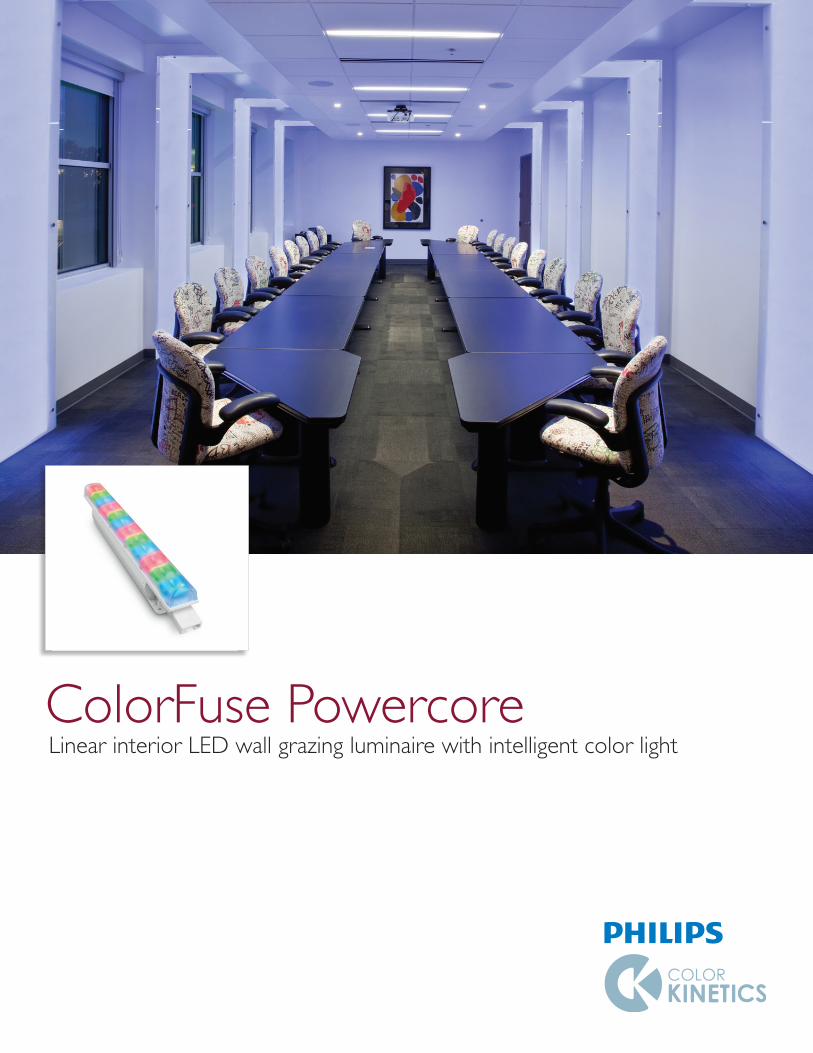
ColorFuse PowercoreLinear interior LED wall grazing luminaire with intelligent color light
ColorFuse Powercore Product Guide2
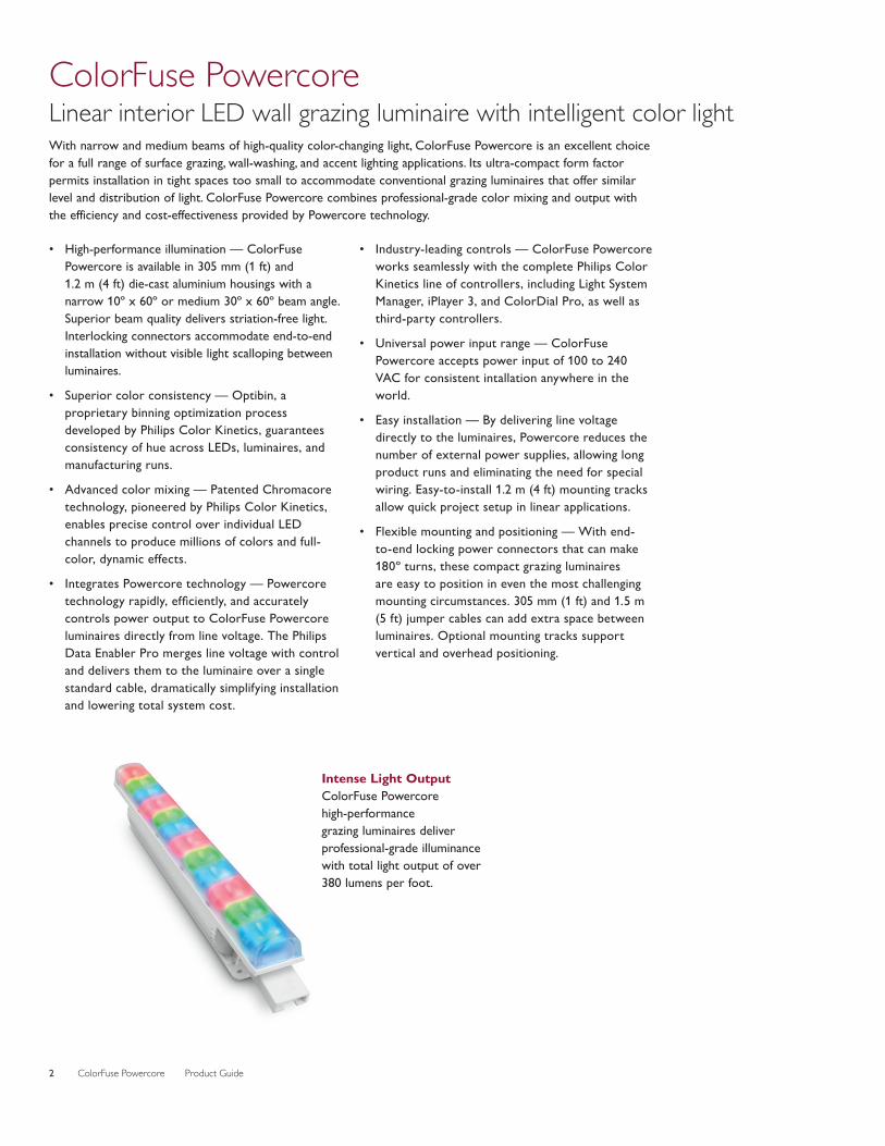
ColorFuse Powercore Linear interior LED wall grazing luminaire with intelligent color lightWith narrow and medium beams of high-quality color-changing light, ColorFuse Powercore is an excellent choice for a full range of surface grazing, wall-washing, and accent lighting applications. Its ultra-compact form factor permits installation in tight spaces too small to accommodate conventional grazing luminaires that offer similar level and distribution of light. ColorFuse Powercore combines professional-grade color mixing and output with the efficiency and cost-effectiveness provided by Powercore technology.
• High-performance illumination — ColorFuse Powercore is available in 305 mm (1 ft) and 1.2 m (4 ft) die-cast aluminium housings with a narrow 10º x 60º or medium 30º x 60º beam angle. Superior beam quality delivers striation-free light. Interlocking connectors accommodate end-to-end installation without visible light scalloping between luminaires.
• Superior color consistency — Optibin, a proprietary binning optimization process developed by Philips Color Kinetics, guarantees consistency of hue across LEDs, luminaires, and manufacturing runs.
• Advanced color mixing — Patented Chromacore
technology, pioneered by Philips Color Kinetics, enables precise control over individual LED channels to produce millions of colors and full-color, dynamic effects.
• Integrates Powercore technology — Powercore technology rapidly, efficiently, and accurately controls power output to ColorFuse Powercore luminaires directly from line voltage. The Philips Data Enabler Pro merges line voltage with control and delivers them to the luminaire over a single standard cable, dramatically simplifying installation and lowering total system cost.
• Industry-leading controls — ColorFuse Powercore works seamlessly with the complete Philips Color Kinetics line of controllers, including Light System Manager, iPlayer 3, and ColorDial Pro, as well as third-party controllers.
• Universal power input range — ColorFuse Powercore accepts power input of 100 to 240 VAC for consistent intallation anywhere in the world.
• Easy installation — By delivering line voltage directly to the luminaires, Powercore reduces the number of external power supplies, allowing long product runs and eliminating the need for special wiring. Easy-to-install 1.2 m (4 ft) mounting tracks allow quick project setup in linear applications.
• Flexible mounting and positioning — With end-to-end locking power connectors that can make 180º turns, these compact grazing luminaires are easy to position in even the most challenging mounting circumstances. 305 mm (1 ft) and 1.5 m (5 ft) jumper cables can add extra space between luminaires. Optional mounting tracks support vertical and overhead positioning.
Intense Light Output ColorFuse Powercore high-performance grazing luminaires deliver professional-grade illuminance with total light output of over 380 lumens per foot.
ColorFuse Powercore Product Guide 3
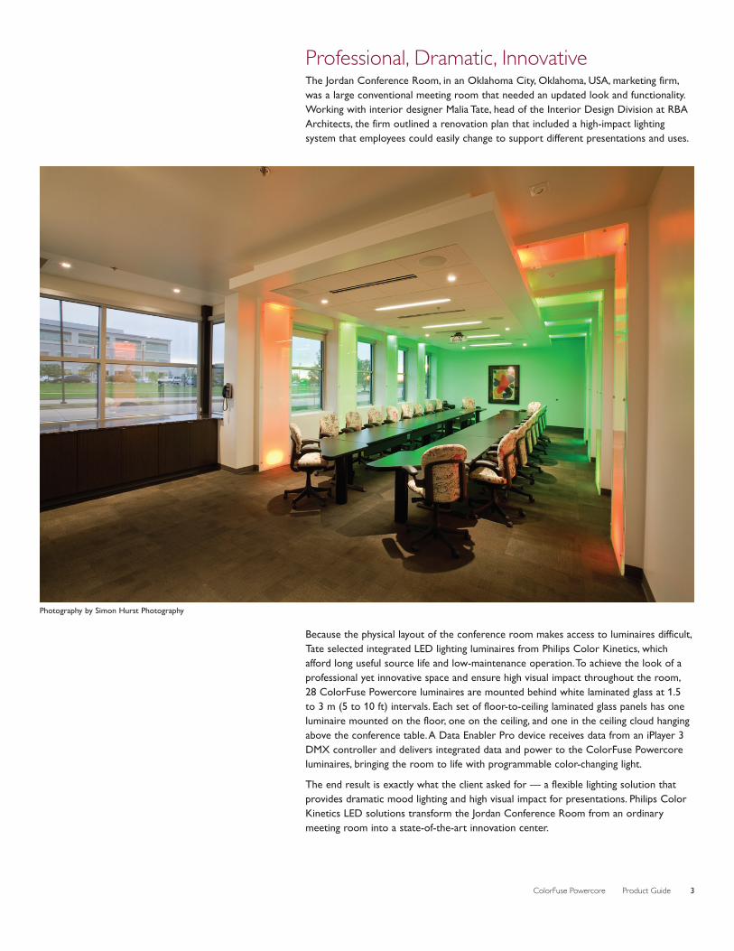
Professional, Dramatic, InnovativeThe Jordan Conference Room, in an Oklahoma City, Oklahoma, USA, marketing firm, was a large conventional meeting room that needed an updated look and functionality. Working with interior designer Malia Tate, head of the Interior Design Division at RBA Architects, the firm outlined a renovation plan that included a high-impact lighting system that employees could easily change to support different presentations and uses.
Because the physical layout of the conference room makes access to luminaires difficult, Tate selected integrated LED lighting luminaires from Philips Color Kinetics, which afford long useful source life and low-maintenance operation. To achieve the look of a professional yet innovative space and ensure high visual impact throughout the room, 28 ColorFuse Powercore luminaires are mounted behind white laminated glass at 1.5 to 3 m (5 to 10 ft) intervals. Each set of floor-to-ceiling laminated glass panels has one luminaire mounted on the floor, one on the ceiling, and one in the ceiling cloud hanging above the conference table. A Data Enabler Pro device receives data from an iPlayer 3 DMX controller and delivers integrated data and power to the ColorFuse Powercore luminaires, bringing the room to life with programmable color-changing light.
The end result is exactly what the client asked for — a flexible lighting solution that provides dramatic mood lighting and high visual impact for presentations. Philips Color Kinetics LED solutions transform the Jordan Conference Room from an ordinary meeting room into a state-of-the-art innovation center.
Photography by Simon Hurst Photography
ColorFuse Powercore Product Guide4
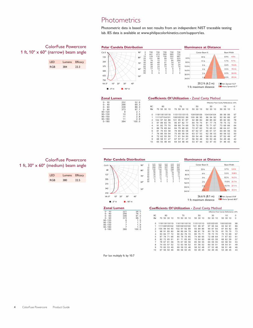
ColorFuse Powercore 1 ft, 10º x 60º (narrow) beam angle Cd: 0
125
250
375
500
625
750VA: 0º 10º 20º 30º 40º
90º
80º
70º
60º
50º
� - 0º H � - 90º H
0.0 22.5 45.0 67.5 90.0 0 706 706 706 706 706 5 441 473 569 685 733 15 129 132 156 352 687 25 101 98 99 151 523 35 79 72 72 85 294 45 85 69 51 34 57 55 49 43 28 18 24 65 28 24 15 12 15 75 17 14 8 6 6 85 8 7 5 3 1 90 6 6 4 2 0
Polar Candela Distribution
Effective Floor Cavity Reflectance: 20%
RC 80 70 50 30 10 0 RW 70 50 30 10 70 50 30 10 50 30 10 50 30 10 50 30 10 0 0 118118118118 115115115115 109109109 104104104 99 99 99 97 1 111107104101 108105102 99 100 98 95 96 94 92 92 90 89 87 2 104 97 92 88 101 95 91 87 92 88 84 88 85 82 85 82 80 78 3 97 89 83 78 95 87 82 77 84 79 75 81 77 74 79 75 72 70 4 91 82 75 70 89 80 74 69 78 72 68 75 71 67 73 69 66 64 5 86 76 69 64 84 75 68 63 72 67 62 70 65 61 68 64 61 59 6 81 70 63 58 79 69 63 58 67 62 57 66 61 57 64 60 56 54 7 76 66 59 54 75 65 58 54 63 57 53 62 56 53 60 56 52 50 8 72 62 55 50 71 61 54 50 59 54 49 58 53 49 57 52 49 47 9 69 58 51 47 67 57 51 47 56 50 46 55 50 46 54 49 46 44 10 65 55 48 44 64 54 48 44 53 47 44 52 47 43 51 46 43 42
Coefficients Of Utilization - Zonal Cavity Method
Center Beam fc Beam Width
4.0 ft
8.0 ft
12.0 ft
16.0 ft
20.0 ft
24.0 ft
44 fc
11 fc
5 fc
3 fc
2 fc
1 fc
0.9 ft
1.7 ft
2.6 ft
3.5 ft
4.3 ft
5.2 ft
4.9 ft
9.7 ft
14.6 ft
19.5 ft
24.4 ft
29.2 ft
�� Vert. Spread: 12.3º�� Horiz. Spread: 62.7º
Illuminance at Distance
ZONE LUMENS %FIXT 0- 30 202 52.6 0- 40 266 69.3 0- 60 339 88.3 0- 90 373 97.1 90-120 8 2.1 90-130 10 2.5 90-150 11 2.8 90-180 11 2.9 0-180 384 100.0
Zonal Lumen
LED Lumens EfficacyRGB 384 23.3
PhotometricsPhotometric data is based on test results from an independent NIST traceable testing lab. IES data is available at www.philipscolorkinetics.com/support/ies.
For lux multiply fc by 10.7
Effective Floor Cavity Reflectance: 20% RC 80 70 50 30 10 0 RW 70 50 30 10 70 50 30 10 50 30 10 50 30 10 50 30 10 0 0 119119119119 116116116116 110110110 105105105 100100100 98 1 111108105102 109106103100 101 99 97 97 95 94 93 92 91 89 2 105 99 94 90 102 97 92 89 93 89 86 90 87 84 87 84 82 80 3 98 91 85 80 96 89 84 79 86 81 78 83 79 76 81 78 75 73 4 93 84 77 72 90 82 76 72 80 75 71 78 73 70 75 72 69 67 5 87 78 71 66 85 76 70 65 74 69 65 72 68 64 71 67 63 61 6 82 72 65 61 81 71 65 60 70 64 60 68 63 59 66 62 59 57 7 78 67 61 56 76 67 60 56 65 59 55 64 59 55 62 58 54 53 8 74 63 57 52 72 63 56 52 61 56 52 60 55 51 59 54 51 49 9 70 60 53 49 69 59 53 48 58 52 48 57 52 48 56 51 48 46 10 67 56 50 46 66 56 50 45 55 49 45 54 49 45 53 48 45 43
Coefficients Of Utilization - Zonal Cavity Method ZONE LUMENS %FIXT 0- 30 221 58.0 0- 40 290 76.1 0- 60 346 91.0 0- 90 373 98.1 90-120 6 1.5 90-130 7 1.7 90-150 7 1.9 90-180 7 1.9 0-180 380 100.0
Zonal Lumen
Center Beam fc Beam Width
4.0 ft
8.0 ft
12.0 ft
16.0 ft
20.0 ft
24.0 ft
25 fc
6 fc
3 fc
2 fc
1 fc
1 fc
2.7 ft
5.5 ft
8.2 ft
11.0 ft
13.7 ft
16.4 ft
5.4 ft
10.8 ft
16.3 ft
21.7 ft
27.1 ft
32.5 ft
�� Vert. Spread: 37.8º�� Horiz. Spread: 68.3º
Illuminance at Distance 0.0 22.5 45.0 67.5 90.0 0 406 406 406 406 406 5 394 396 399 403 404 15 259 278 327 366 381 25 128 144 192 268 299 35 66 69 92 151 193 45 39 40 44 49 54 55 26 24 22 19 21 65 19 17 13 12 13 75 12 10 7 6 6 85 6 5 4 3 1 90 5 4 3 2 1
Polar Candela DistributionCd: 0
68
137
205
273
342
410VA: 0º 10º 20º 30º 40º
90º
80º
70º
60º
50º
� - 0º H � - 90º H
ColorFuse Powercore 1 ft, 30º x 60º (medium) beam angle
LED Lumens EfficacyRGB 380 22.5
20.2 ft (6.2 m) 1 fc maximum distance
26.6 ft (8.1 m) 1 fc maximum distance
ColorFuse Powercore Product Guide 5
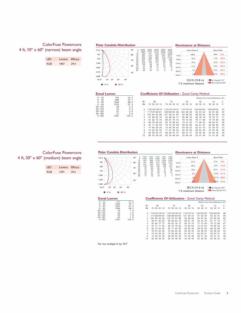
ColorFuse Powercore 4 ft, 10º x 60º (narrow) beam angle Cd: 0
467
933
1,400
1,867
2,333
2,800VA: 0º 10º 20º 30º 40º
90º
80º
70º
60º
50º
� - 0º H � - 90º H
0.0 22.5 45.0 67.5 90.0 0 2695 2695 2695 2695 2695 5 1686 1797 2144 2558 2739 15 465 471 553 1327 2608 25 390 375 365 557 2011 35 292 290 282 318 1109 45 307 251 193 125 248 55 166 150 107 66 86 65 102 82 54 41 53 75 57 48 31 22 23 85 30 27 17 9 4 90 24 23 13 6 0
Polar Candela Distribution
Effective Floor Cavity Reflectance: 20%
RC 80 70 50 30 10 0 RW 70 50 30 10 70 50 30 10 50 30 10 50 30 10 50 30 10 0
0 118118118118 115115115115 110110110 104104104 100100100 97 1 111107104101 108105102 99 100 98 96 96 94 92 92 91 89 87 2 104 98 93 88 101 96 91 87 92 88 85 88 85 82 85 83 80 78 3 97 89 83 78 95 88 82 77 85 80 76 82 78 74 79 76 73 71 4 91 82 75 70 89 81 75 70 78 73 69 76 71 68 73 70 66 65 5 86 76 69 64 84 75 68 64 73 67 63 71 66 62 69 64 61 59 6 81 71 64 59 79 70 63 58 68 62 58 66 61 57 64 60 56 55 7 77 66 59 54 75 65 59 54 64 58 53 62 57 53 61 56 53 51 8 73 62 55 50 71 61 55 50 60 54 50 58 53 49 57 53 49 48 9 69 58 52 47 68 58 51 47 56 51 47 55 50 46 54 50 46 45 10 66 55 49 44 65 54 48 44 53 48 44 52 47 44 51 47 43 42
Coefficients Of Utilization - Zonal Cavity Method ZONE LUMENS %FIXT 0- 30 745 53.0 0- 40 986 70.1 0- 60 1249 88.8 0- 90 1370 97.4 90-120 28 2.0 90-130 33 2.4 90-150 37 2.6 90-180 37 2.6 0-180 1407 100.0
Zonal Lumen
LED Lumens EfficacyRGB 1407 29.4
For lux multiply fc by 10.7
Effective Floor Cavity Reflectance: 20%
RC 80 70 50 30 10 0 RW 70 50 30 10 70 50 30 10 50 30 10 50 30 10 50 30 10 0
0 119119119119 116116116116 110110110 105105105 100100100 98 1 111108105102 109106103100 101 99 97 97 95 94 93 92 91 89 2 105 99 94 90 102 97 92 88 93 89 86 90 87 84 87 84 82 80 3 98 91 85 80 96 89 84 79 86 81 78 83 79 76 81 77 75 73 4 92 84 77 72 90 82 76 72 80 75 70 77 73 69 75 72 68 67 5 87 77 71 66 85 76 70 65 74 69 64 72 67 64 70 66 63 61 6 82 72 65 60 80 71 65 60 69 64 59 68 63 59 66 62 58 57 7 78 67 60 56 76 66 60 55 65 59 55 64 58 55 62 58 54 53 8 74 63 56 52 72 62 56 52 61 55 51 60 55 51 59 54 51 49 9 70 59 53 48 69 59 52 48 57 52 48 56 51 48 55 51 47 46 10 66 56 49 45 65 55 49 45 54 49 45 53 48 45 52 48 44 43
Coefficients Of Utilization - Zonal Cavity Method ZONE LUMENS %FIXT 0- 30 797 57.3 0- 40 1053 75.7 0- 60 1267 91.2 0- 90 1366 98.2 90-120 19 1.4 90-130 22 1.6 90-150 25 1.8 90-180 25 1.8 0-180 1391 100.0
Zonal Lumen
0.0 22.5 45.0 67.5 90.0 0 1460 1460 1460 1460 1460 5 1423 1424 1436 1451 1465 15 937 996 1178 1326 1378 25 441 489 677 1012 1127 35 241 244 318 568 773 45 146 149 162 184 241 55 97 88 85 70 81 65 70 62 46 41 48 75 43 37 26 22 21 85 22 20 13 9 4 90 17 16 10 5 1
Polar Candela DistributionCd: 0
250
500
750
1,000
1,250
1,500VA: 0º 10º 20º 30º 40º
90º
80º
70º
60º
50º
� - 0º H � - 90º H
ColorFuse Powercore 4 ft, 30º x 60º (medium) beam angle
LED Lumens EfficacyRGB 1391 29.2
Center Beam fc Beam Width
4.0 ft
8.0 ft
12.0 ft
16.0 ft
20.0 ft
24.0 ft
168 fc
42 fc
19 fc
11 fc
7 fc
5 fc
0.8 ft
1.7 ft
2.5 ft
3.4 ft
4.2 ft
5.1 ft
5.0 ft
10.0 ft
15.0 ft
20.0 ft
25.0 ft
30.0 ft
�� Vert. Spread: 12.1º�� Horiz. Spread: 64.0º
Illuminance at Distance
Center Beam fc Beam Width
4.0 ft
8.0 ft
12.0 ft
16.0 ft
20.0 ft
24.0 ft
91 fc
23 fc
10 fc
6 fc
4 fc
3 fc
2.7 ft
5.5 ft
8.2 ft
11.0 ft
13.7 ft
16.5 ft
5.8 ft
11.5 ft
17.3 ft
23.1 ft
28.8 ft
34.6 ft
�� Vert. Spread: 37.9º�� Horiz. Spread: 71.5º
Illuminance at Distance
38.2 ft (11.6 m) 1 fc maximum distance
52.0 ft (15.8 m) 1 fc maximum distance
ColorFuse Powercore Product Guide6
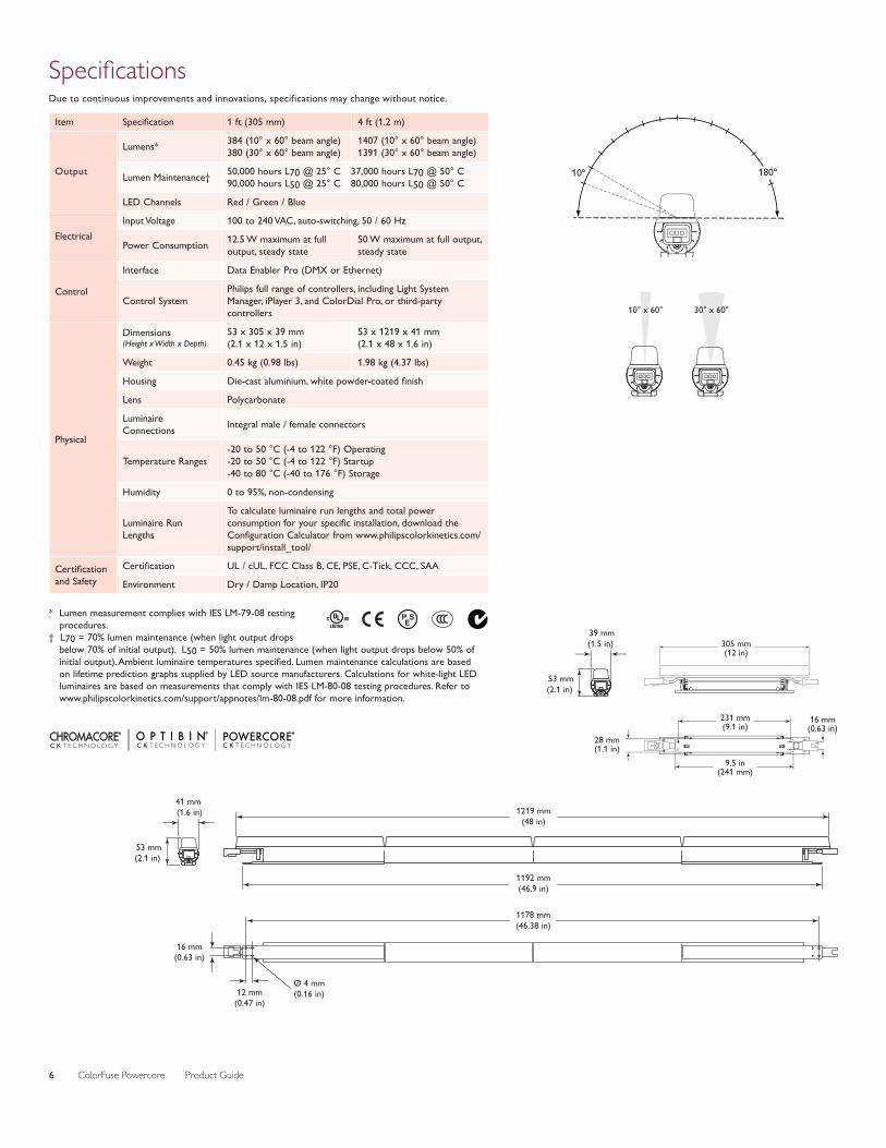
SpecificationsDue to continuous improvements and innovations, specifications may change without notice.
10º
10° x 60° 30° x 60°
180º
10º
10° x 60° 30° x 60°
180º
51 mm(2.00 in)
LIGHT
231 mm(9.1 in)
9.5 in(241 mm)
28 mm(1.1 in)
16 mm(0.63 in)
305 mm(12 in)
39 mm(1.5 in)
53 mm(2.1 in)
Item Specification 1 ft (305 mm) 4 ft (1.2 m)
Output
Lumens* 384 (10° x 60° beam angle) 380 (30° x 60° beam angle)
1407 (10° x 60° beam angle) 1391 (30° x 60° beam angle)
Lumen Maintenance† 50,000 hours L70 @ 25° C 37,000 hours L70 @ 50° C 90,000 hours L50 @ 25° C 80,000 hours L50 @ 50° C
LED Channels Red / Green / Blue
ElectricalInput Voltage 100 to 240 VAC, auto-switching, 50 / 60 Hz
Power Consumption 12.5 W maximum at full output, steady state
50 W maximum at full output, steady state
Control
Interface Data Enabler Pro (DMX or Ethernet)
Control SystemPhilips full range of controllers, including Light System Manager, iPlayer 3, and ColorDial Pro, or third-party controllers
Physical
Dimensions (Height x Width x Depth)
53 x 305 x 39 mm (2.1 x 12 x 1.5 in)
53 x 1219 x 41 mm (2.1 x 48 x 1.6 in)
Weight 0.45 kg (0.98 lbs) 1.98 kg (4.37 lbs)
Housing Die-cast aluminium, white powder-coated finish
Lens Polycarbonate
Luminaire Connections Integral male / female connectors
Temperature Ranges-20 to 50 °C (-4 to 122 °F) Operating -20 to 50 °C (-4 to 122 °F) Startup -40 to 80 °C (-40 to 176 °F) Storage
Humidity 0 to 95%, non-condensing
Luminaire Run Lengths
To calculate luminaire run lengths and total power consumption for your specific installation, download the Configuration Calculator from www.philipscolorkinetics.com/support/install_tool/
Certification and Safety
Certification UL / cUL, FCC Class B, CE, PSE, C-Tick, CCC, SAA
Environment Dry / Damp Location, IP20
* Lumen measurement complies with IES LM-79-08 testing procedures.
† L70 = 70% lumen maintenance (when light output drops below 70% of initial output). L50 = 50% lumen maintenance (when light output drops below 50% of initial output). Ambient luminaire temperatures specified. Lumen maintenance calculations are based on lifetime prediction graphs supplied by LED source manufacturers. Calculations for white-light LED luminaires are based on measurements that comply with IES LM-80-08 testing procedures. Refer to www.philipscolorkinetics.com/support/appnotes/lm-80-08.pdf for more information.
1192 mm(46.9 in)
1178 mm(46.38 in)
1219 mm(48 in)
Ø 4 mm(0.16 in)12 mm
(0.47 in)
16 mm(0.63 in)
41 mm (1.6 in)
53 mm(2.1 in)
ColorFuse Powercore Product Guide 7
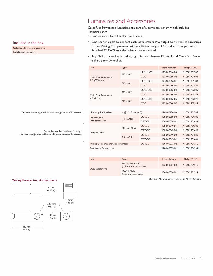
Item Type Item Number Philips 12NC
ColorFuse Powercore 1 ft (305 mm)
10° x 60°UL/cUL/CE 123-000066-00 910503701783
CCC 123-000066-02 910503701993
30° x 60°UL/cUL/CE 123-000066-01 910503701784
CCC 123-000066-03 910503701994
ColorFuse Powercore 4 ft (1.2 m)
10° x 60°UL/cUL/CE 123-000066-04 910503702589
CCC 123-000066-06 910503703167
30° x 60°UL/cUL/CE 123-000066-05 910503702590
CCC 123-000066-07 910503703168
Optional mounting track ensures straight runs of luminaires. Mounting Track, White 1 @ 1219 mm (4 ft) 120-000124-00 910503701787
Leader Cable with Terminator 3.1 m (10 ft)
UL/cUL 108-000050-00 910503701686
CE/CCC 108-000050-01 910503701687
Depending on the installation’s design, you may need jumper cables to add space between luminaires. Jumper Cable
305 mm (1 ft)UL/cUL 108-000049-01 910503701683
CE/CCC 108-000049-03 910503701685
1.5 m (5 ft)UL/cUL 108-000049-00 910503701682
CE/CCC 108-000049-02 910503701684
Wiring Compartment with Terminator UL/cUL 120-000077-02 910503701740
Terminator, Quantity 10 120-000099-01 910503704251
Luminaires and AccessoriesColorFuse Powercore luminaires are part of a complete system which includes luminaires and:• One or more Data Enabler Pro devices.
• One Leader Cable to connect each Data Enabler Pro output to a series of luminaires, or one Wiring Compartment with a sufficient length of 4-conductor copper wire. Standard 12 AWG stranded wire is recommended.
• Any Philips controller, including Light System Manager, iPlayer 3, and ColorDial Pro, or a third-party controller.
Use Item Number when ordering in North America.
Included in the boxColorFuse Powercore luminaireInstallation Instructions
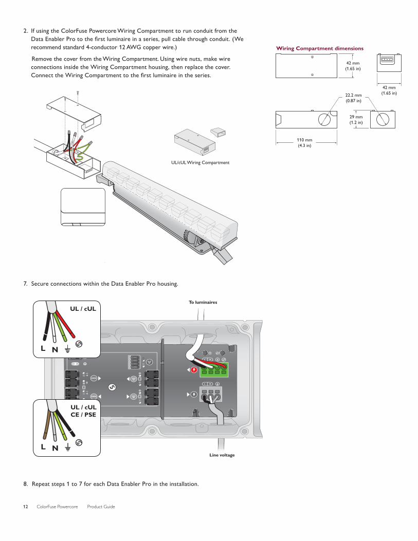
42 mm(1.65 in)
42 mm(1.65 in)22.2 mm
(0.87 in)
29 mm(1.2 in)
110 mm(4.3 in)
Wiring Compartment dimensions
Item Type Item Number Philips 12NC
Data Enabler Pro
3/4 in / 1/2 in NPT (U.S. trade size conduit) 106-000004-00 910503701210
PG21 / PG13 (metric size conduit) 106-000004-01 910503701211
ColorFuse Powercore Product Guide8
InstallationColorFuse Powercore offers high-intensity, full-color surface grazing and wall washing with Powercore technology. Powercore, which integrates LED power and data management within the luminaire, eases installation by eliminating the need for external power supplies.
Owner / User Responsibilities It is the responsibility of the contractor, installer, purchaser, owner, and user to install, maintain, and operate ColorFuse Powercore luminaires in such a manner as to comply with all applicable codes, state and local laws, ordinances, and regulations. Consult with the appropriate electrical inspector to ensure compliance.
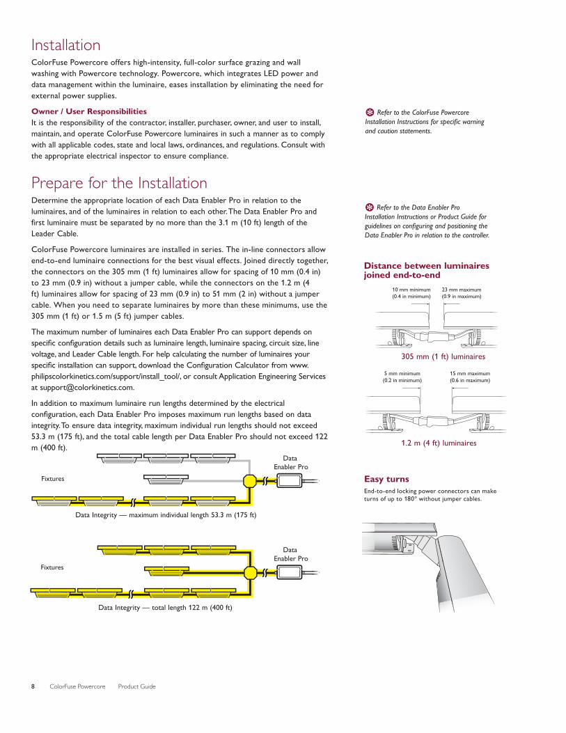
Prepare for the InstallationDetermine the appropriate location of each Data Enabler Pro in relation to the luminaires, and of the luminaires in relation to each other. The Data Enabler Pro and first luminaire must be separated by no more than the 3.1 m (10 ft) length of the Leader Cable.
ColorFuse Powercore luminaires are installed in series. The in-line connectors allow end-to-end luminaire connections for the best visual effects. Joined directly together, the connectors on the 305 mm (1 ft) luminaires allow for spacing of 10 mm (0.4 in) to 23 mm (0.9 in) without a jumper cable, while the connectors on the 1.2 m (4 ft) luminaires allow for spacing of 23 mm (0.9 in) to 51 mm (2 in) without a jumper cable. When you need to separate luminaires by more than these minimums, use the 305 mm (1 ft) or 1.5 m (5 ft) jumper cables.
The maximum number of luminaires each Data Enabler Pro can support depends on specific configuration details such as luminaire length, luminaire spacing, circuit size, line voltage, and Leader Cable length. For help calculating the number of luminaires your specific installation can support, download the Configuration Calculator from www.philipscolorkinetics.com/support/install_tool/, or consult Application Engineering Services at [email protected].
In addition to maximum luminaire run lengths determined by the electrical configuration, each Data Enabler Pro imposes maximum run lengths based on data integrity. To ensure data integrity, maximum individual run lengths should not exceed 53.3 m (175 ft), and the total cable length per Data Enabler Pro should not exceed 122 m (400 ft).
Fixtures
Fixtures
Data Enabler Pro
Data Enabler Pro
Fixtures
Fixtures
Data Enabler Pro
Data Enabler Pro
Data Integrity — maximum individual length 53.3 m (175 ft)
Data Integrity — total length 122 m (400 ft)
E Refer to the ColorFuse Powercore Installation Instructions for specific warning and caution statements.
E Refer to the Data Enabler Pro Installation Instructions or Product Guide for guidelines on configuring and positioning the Data Enabler Pro in relation to the controller.
Distance between luminaires joined end-to-end
10 mm minimum(0.4 in minimum)
23 mm maximum(0.9 in maximum)
5 mm minimum(0.2 in minimum)
15 mm maximum(0.6 in maximum)
305 mm (1 ft) luminaires
1.2 m (4 ft) luminaires
Easy turnsEnd-to-end locking power connectors can make turns of up to 180º without jumper cables.
ColorFuse Powercore Product Guide 9
Start the Installation1. Install all Data Enabler Pro devices, including any interfaces with controllers.
One Leader Cable is required to connect each run or series of luminaires to a Data Enabler Pro. The Data Enabler Pro sends power and control signals to the luminaires over the Leader Cable.
2. Verify that all additional supporting equipment (switches, controllers) is in place.
3. If your installation calls for Jumper Cables to add space between luminaires, make sure they are available.
4. Ensure that all additional parts (optional mounting tracks, mounting hardware, terminators) and tools are available.
Unpack and Prepare Luminaires1. Carefully inspect the box containing ColorFuse Powercore and the contents for any
damage that may have occurred in transit.
2. On an architectural diagram or other diagram that shows the physical layout of the installation, identify the locations of all switches, controllers, power supplies, luminaires, and Leader and Jumper Cables.
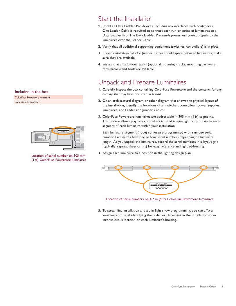
3. ColorFuse Powercore luminaires are addressable in 305 mm (1 ft) segments. This feature allows playback controllers to send unique light output data to each segment of each luminaire within your installation.
Each luminaire segment (node) comes pre-programmed with a unique serial number. Luminaires have one or four serial numbers depending on luminaire length. As you unpack the luminaires, record the serial numbers in a layout grid (typically a spreadsheet or list) for easy reference and light addressing.
4. Assign each luminaire to a position in the lighting design plan.
5. To streamline installation and aid in light show programming, you can affix a weatherproof label identifying the order or placement in the installation to an inconspicuous location on each luminaire’s housing.
SERIAL NUMBER
00000000
Included in the boxColorFuse Powercore luminaireInstallation Instructions
Location of serial number on 305 mm (1 ft) ColorFuse Powercore luminaires
SERIAL NUMBER
00000000SERIAL NUMBER
00000000SERIAL NUMBER
00000000SERIAL NUMBER
00000000
SERIAL NUMBER
00000000
Location of serial numbers on 1.2 m (4 ft) ColorFuse Powercore luminaires
ColorFuse Powercore Product Guide10
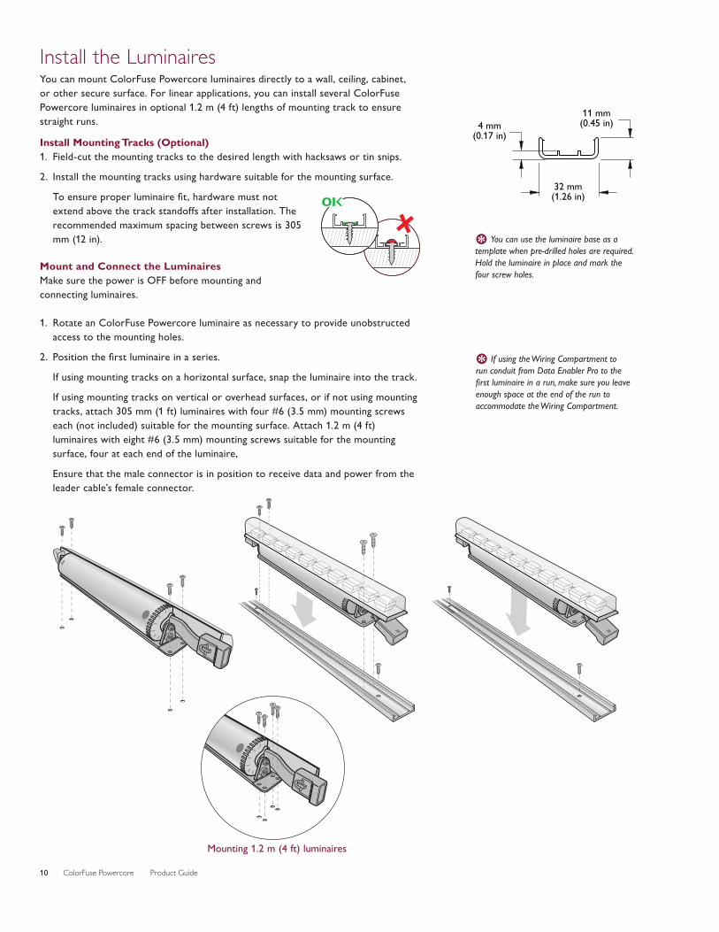
Install the LuminairesYou can mount ColorFuse Powercore luminaires directly to a wall, ceiling, cabinet, or other secure surface. For linear applications, you can install several ColorFuse Powercore luminaires in optional 1.2 m (4 ft) lengths of mounting track to ensure straight runs.
Install Mounting Tracks (Optional)1. Field-cut the mounting tracks to the desired length with hacksaws or tin snips.
2. Install the mounting tracks using hardware suitable for the mounting surface.
To ensure proper luminaire fit, hardware must not extend above the track standoffs after installation. The recommended maximum spacing between screws is 305 mm (12 in).
Mount and Connect the LuminairesMake sure the power is OFF before mounting and connecting luminaires.
1. Rotate an ColorFuse Powercore luminaire as necessary to provide unobstructed access to the mounting holes.
2. Position the first luminaire in a series.
If using mounting tracks on a horizontal surface, snap the luminaire into the track.
If using mounting tracks on vertical or overhead surfaces, or if not using mounting tracks, attach 305 mm (1 ft) luminaires with four #6 (3.5 mm) mounting screws each (not included) suitable for the mounting surface. Attach 1.2 m (4 ft) luminaires with eight #6 (3.5 mm) mounting screws suitable for the mounting surface, four at each end of the luminaire,
Ensure that the male connector is in position to receive data and power from the leader cable’s female connector.
E You can use the luminaire base as a template when pre-drilled holes are required. Hold the luminaire in place and mark the four screw holes.
E If using the Wiring Compartment to run conduit from Data Enabler Pro to the first luminaire in a run, make sure you leave enough space at the end of the run to accommodate the Wiring Compartment.
IN IN
Mounting 1.2 m (4 ft) luminaires
OK
4 mm(0.17 in)
11 mm(0.45 in)
32 mm(1.26 in)
ININ

ColorFuse Powercore Product Guide 11
CLICK!
3. Position the next luminaire in the series, matching the male connector end to the female connector of the previously mounted luminaire. Attach the luminaire to the surface or snap it into the track.
4. Continue mounting the luminaires, making power/data connections as you go, until all lights in the series are mounted.
5. Insert the provided terminator into the last luminaire in the series.
Make Power Connections1. If using a Leader Cable, connect the Leader Cable to the first luminaire in the
series. Run the Leader Cable to the Data Enabler Pro.
Data Enabler Pro
Leader Cable
Leader Cable connector dimensions
10 mm(0.37 in)
13.5 mm(0.53 in)
24 mm(0.94 in)
55.6 mm(2.2 in)
10 mm(0.37 in)
13.5 mm(0.53 in)
24 mm(0.94 in)
55.6 mm(2.2 in)
ColorFuse Powercore Product Guide12
2. If using the ColorFuse Powercore Wiring Compartment to run conduit from the Data Enabler Pro to the first luminaire in a series, pull cable through conduit. (We recommend standard 4-conductor 12 AWG copper wire.)
Remove the cover from the Wiring Compartment. Using wire nuts, make wire connections inside the Wiring Compartment housing, then replace the cover. Connect the Wiring Compartment to the first luminaire in the series.
7. Secure connections within the Data Enabler Pro housing.
8. Repeat steps 1 to 7 for each Data Enabler Pro in the installation.
L N
L N
DMX
DMX
To luminaires
UL / cUL
UL / cUL
LN
CE / PSE
CE / PSE UL / cULCE / PSE
LN
UL / cUL CE / PSEL
NL
N
L N L N
UL / cUL CE / PSE
L N L N
L N
UL / cUL
UL / cUL
LN
CE / PSE
CE / PSE UL / cULCE / PSE
LN
UL / cUL CE / PSEL
NL
N
L N L N
UL / cUL CE / PSE
L N L N
L NLine voltage
42 mm(1.65 in)
42 mm(1.65 in)22.2 mm
(0.87 in)
29 mm(1.2 in)
110 mm(4.3 in)
Wiring Compartment dimensions
UL / cUL
UL / cUL
LN
CE / PSE
CE / PSE UL / cULCE / PSE
LN
UL / cUL CE / PSEL
NL
N
L N L N
UL / cUL CE / PSE
L N L N
L N
UL/cUL Wiring Compartment
ColorFuse Powercore Product Guide 13
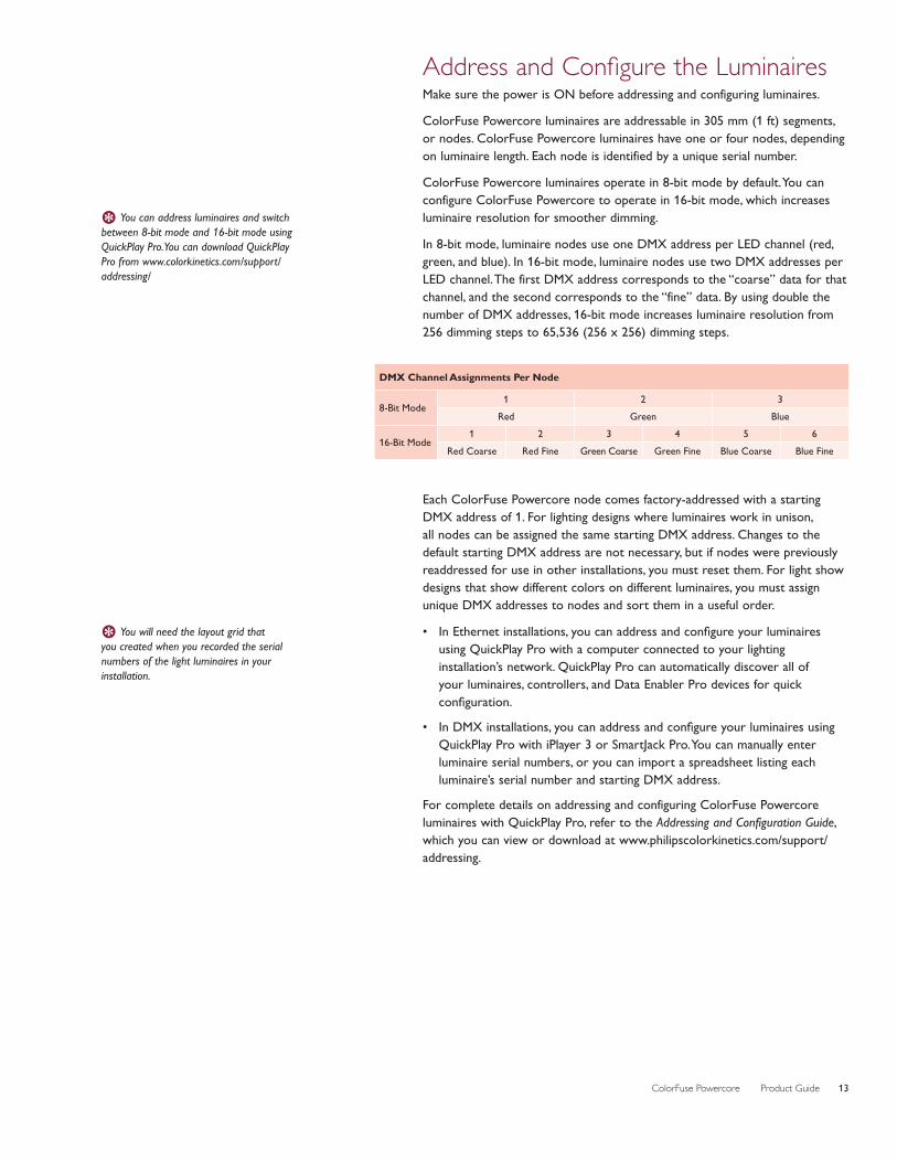
DMX Channel Assignments Per Node
8-Bit Mode1 2 3
Red Green Blue
16-Bit Mode1 2 3 4 5 6
Red Coarse Red Fine Green Coarse Green Fine Blue Coarse Blue Fine
E You will need the layout grid that you created when you recorded the serial numbers of the light luminaires in your installation.
E You can address luminaires and switch between 8-bit mode and 16-bit mode using QuickPlay Pro. You can download QuickPlay Pro from www.colorkinetics.com/support/addressing/
Address and Configure the Luminaires Make sure the power is ON before addressing and configuring luminaires.
ColorFuse Powercore luminaires are addressable in 305 mm (1 ft) segments, or nodes. ColorFuse Powercore luminaires have one or four nodes, depending on luminaire length. Each node is identified by a unique serial number.
ColorFuse Powercore luminaires operate in 8-bit mode by default. You can configure ColorFuse Powercore to operate in 16-bit mode, which increases luminaire resolution for smoother dimming.
In 8-bit mode, luminaire nodes use one DMX address per LED channel (red, green, and blue). In 16-bit mode, luminaire nodes use two DMX addresses per LED channel. The first DMX address corresponds to the “coarse” data for that channel, and the second corresponds to the “fine” data. By using double the number of DMX addresses, 16-bit mode increases luminaire resolution from 256 dimming steps to 65,536 (256 x 256) dimming steps.
Each ColorFuse Powercore node comes factory-addressed with a starting DMX address of 1. For lighting designs where luminaires work in unison, all nodes can be assigned the same starting DMX address. Changes to the default starting DMX address are not necessary, but if nodes were previously readdressed for use in other installations, you must reset them. For light show designs that show different colors on different luminaires, you must assign unique DMX addresses to nodes and sort them in a useful order.
• In Ethernet installations, you can address and configure your luminaires using QuickPlay Pro with a computer connected to your lighting installation’s network. QuickPlay Pro can automatically discover all of your luminaires, controllers, and Data Enabler Pro devices for quick configuration.
• In DMX installations, you can address and configure your luminaires using QuickPlay Pro with iPlayer 3 or SmartJack Pro. You can manually enter luminaire serial numbers, or you can import a spreadsheet listing each luminaire’s serial number and starting DMX address.
For complete details on addressing and configuring ColorFuse Powercore luminaires with QuickPlay Pro, refer to the Addressing and Configuration Guide, which you can view or download at www.philipscolorkinetics.com/support/addressing.
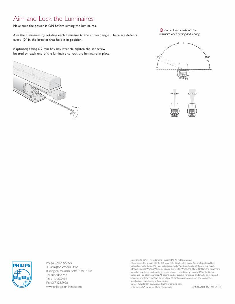
Aim and Lock the LuminairesMake sure the power is ON before aiming the luminaires.
Aim the luminaires by rotating each luminaire to the correct angle. There are detents every 10° in the bracket that hold it in position. (Optional) Using a 2 mm hex key wrench, tighten the set screw located on each end of the luminaire to lock the luminaire in place.
10º
10° x 60° 30° x 60°
180º
10º
10° x 60° 30° x 60°
180º2 mm
ININ
E Do not look directly into the luminaire when aiming and locking.
Philips Color Kinetics3 Burlington Woods DriveBurlington, Massachusetts 01803 USATel 888.385.5742Tel 617.423.9999Fax 617.423.9998www.philipscolorkinetics.com
Copyright © 2017 Philips Lighting Holding B.V. All rights reserved. Chromacore, Chromasic, CK, the CK logo, Color Kinetics, the Color Kinetics logo, ColorBlast, ColorBlaze, ColorBurst, eW Fuse, ColorGraze, ColorPlay, ColorReach, iW Reach, eW Reach, DIMand, EssentialWhite, eW, iColor, iColor Cove, IntelliWhite, iW, iPlayer, Optibin, and Powercore are either registered trademarks or trademarks of Philips Lighting Holding B.V. in the United States and / or other countries. All other brand or product names are trademarks or registered trademarks of their respective owners. Due to continuous improvements and innovations, specifications may change without notice.Cover Photo: Jordan Conference Room, Oklahoma City, Oklahoma, USA by Simon Hurst Photography DAS-000078-00 R04 09-17
Top Related