


Languages
Pages
Legal


COE4OI5Engineering Design
UP3core Library Functions

2Copyright S. Shirani
UP3core library functions
• In complex designs, intellectual property (IP) cores are frequently used.
• An IP core is a previously developed synthesizable hardware design that provides a widely used functions.
• Some of IP cores are commercially licensed • IP cores reduce development time by providing common
hardware functions for use in a new design.

3Copyright S. Shirani
UP3core libraryLCD_Display Displays ASCII characters and Hex data on the
UP3’s LCD panelDEBOUNCE Pushbutton debounce circuit
ONEPULSE Pushbutton single pulse circuit
CLK_DIV 25MHz (48 MHz for UP3) clock divider with 7 frequency outputs
VGA_SYNC VGA synch signal generator
Video_PLL Used by VGA-sync to generate the video pixel clock using a PLL
CHAR_ROM Character font ROM for video character generations
KEYBOARD Reads keyboard scan codes from the UP2 or UP3 PS/2 connector
MOUSE Reads mouse data and outputs cursor row and column address

4Copyright S. Shirani
UP3core library• UP3core functions can be used in schematic capture, VHDL,
or Verilog based designs• Full code is provided on the CD• For correct operation of the functions, I/O pin assignments
must be made as shown in the description of each UP3core function
• Several of functions require a clock• Clk_Div is setup to provide the slower clock signal needed by
some of the core functions.• Source code for the UP3core functions must be in the project
directory or in the user’s library search path

5Copyright S. Shirani
UP3core library• The VGA-Sync, Video_PLL and LCD_Display core functions
are often modified by the user to support different display resolutions.
• Since UP2 does not have an LCD display, the seven segment core, DEC_7SEG must be used
• On UP2 only 640 by 480 video mode is possible
6Copyright S. Shirani
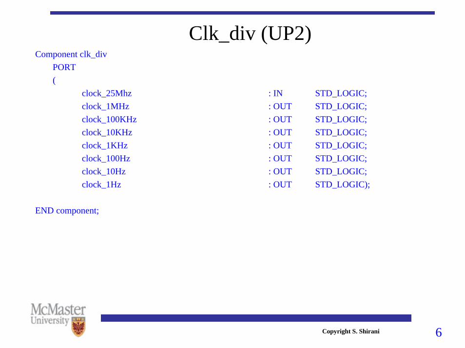
Clk_div (UP2)Component clk_div
PORT(
clock_25Mhz : IN STD_LOGIC;clock_1MHz : OUT STD_LOGIC;clock_100KHz : OUT STD_LOGIC;clock_10KHz : OUT STD_LOGIC;clock_1KHz : OUT STD_LOGIC;clock_100Hz : OUT STD_LOGIC;clock_10Hz : OUT STD_LOGIC;clock_1Hz : OUT STD_LOGIC);
END component;

7Copyright S. Shirani
Clk_div (UP3)Component clk_div
PORT(
clock_48Mhz : IN STD_LOGIC;clock_1MHz : OUT STD_LOGIC;clock_100KHz : OUT STD_LOGIC;clock_10KHz : OUT STD_LOGIC;clock_1KHz : OUT STD_LOGIC;clock_100Hz : OUT STD_LOGIC;clock_10Hz : OUT STD_LOGIC;clock_1Hz : OUT STD_LOGIC);
END component;clk_div
inst
clock_48Mhzclock_48Mhz clock_1MHzclock_1MHz
clock_100KHzclock_100KHz
clock_10KHzclock_10KHz
clock_1KHzclock_1KHz
clock_100Hzclock_100Hz
clock_10Hzclock_10Hz
clock_1Hzclock_1Hz

8Copyright S. Shirani
Seven segment decoder (UP2)
COMPONENT dec_7segPORT(hex_digit : IN STD_LOGIC_VECTOR(3 downto 0);
seg_a, seg_b, seg_c, seg_d,seg_e, seg_f, seg_g : OUT STD_LOGIC);
END COMPONENT;
9Copyright S. Shirani
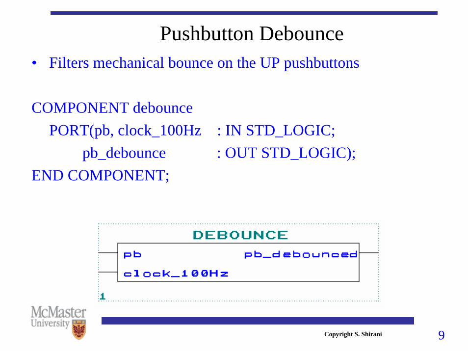
Pushbutton Debounce• Filters mechanical bounce on the UP pushbuttons
COMPONENT debouncePORT(pb, clock_100Hz : IN STD_LOGIC;
pb_debounce : OUT STD_LOGIC);END COMPONENT;

10Copyright S. Shirani
• Output from the pushbutton is high for only one clock cycle no matter how long the pushbutton is depressed
• This function is useful in state machines that read external inputs
COMPONENT onepulsePORT(pb_debounce, clock : IN STD_LOGIC;
pb_single_pulse : OUT STD_LOGIC);END COMPONENT;
Pushbutton Single Pulse
11Copyright S. Shirani
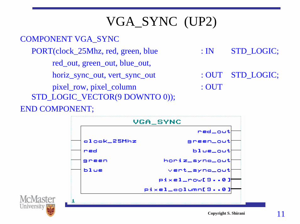
VGA_SYNC (UP2)COMPONENT VGA_SYNC
PORT(clock_25Mhz, red, green, blue : IN STD_LOGIC;red_out, green_out, blue_out, horiz_sync_out, vert_sync_out : OUT STD_LOGIC;pixel_row, pixel_column : OUT
STD_LOGIC_VECTOR(9 DOWNTO 0));END COMPONENT;

12Copyright S. Shirani
Video display• VGA video signal: 5 active signals
– Horizontal Sync. & Vertical Sync– RGB: red, green and blue signals
• Screen has 640x480 pixels• Video signal redraws the entire screen 60 times per second

13Copyright S. Shirani
Video display• Major component inside a VGA computer monitor is the color
CRT.• Electron beam is scanned over the screen in a sequence of
horizontal lines to generate an image• Light is generated when the beam is turned on by a video
signal and it strikes a color phosphor on the CRT.• Face of CRT contains three different phosphors one type for
each primary color (red, green, blue)

14Copyright S. Shirani
0,0
639,479
640 Pixels in a row
480 Pixels in a column
0,479
639,0
480 Horizontal Scan Lines and Retrace .
.
.
VGA Image - 640 by 480 Pixel Layout.

15Copyright S. Shirani
VGA display
Generation of colors of pixels based on their
location on the display
16Copyright S. Shirani
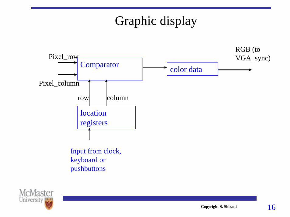
Graphic display
Comparator
location registers
color data
Input from clock, keyboard or pushbuttons
Pixel_row
Pixel_column
row column
RGB (to VGA_sync)

17Copyright S. Shirani
Video LED Design Example
18Copyright S. Shirani
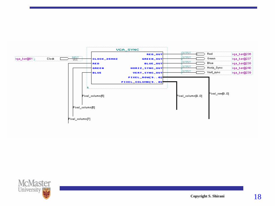
Video Color Bar Design Example

19Copyright S. Shirani
UP3
VGA_SYNC
inst
clock_48Mhzclock_48Mhz
redred
greengreen
blueblue
red_outred_out
green_outgreen_out
blue_outblue_out
horiz_sync_outhoriz_sync_out
vert_sync_outvert_sync_out
video_onvideo_on
pixel_clockpixel_clock
pixel_row[9..0]pixel_row[9..0]
pixel_column[9..0]pixel_column[9..0]
COMPONENT VGA_SYNCPORT(clock_48Mhz, red, green, blue : IN STD_LOGIC;
red_out, green_out, blue_out, horiz_sync_out, vert_sync_out, video_on, pixel_clock
: OUT STD_LOGIC;pixel_row, pixel_column : OUT
STD_LOGIC_VECTOR(9 DOWNTO 0));END COMPONENT;

20Copyright S. Shirani
VGA-Sync (UP3)• Compared to UP2, UP3 VGA-Sync has two extra outputs:
– Video_on: indicates that pixel data is being displayed and a retrace cycle is not presently occurring
– Pixel_clock: provides the current pixel clock
• A table of common screen resolutions and refresh rates along with the required pixel clocks and sync count values can be found at the end of the VGA-Sync core.
• video_pll should be adjusted to output a different pixel clock rate (use MegaWizard edit)
• video_pll must be present to compile VGA-Sync since it uses this component for the clock.

21Copyright S. Shirani
Common Video Modes - pixel clock and sync counter values
• --• -- Mode Refresh Hor. Sync Pixel clock Interlaced? • -- ------------------------------------------------------------• -- 640x480 60Hz 31.5khz 25.175Mhz No • -- 640x480 63Hz 32.8khz 28.322Mhz No • -- 640x480 70Hz 36.5khz 31.5Mhz No • -- 640x480 72Hz 37.9khz 31.5Mhz No • -- 800x600 56Hz 35.1khz 36.0Mhz No • -- 800x600 56Hz 35.4khz 36.0Mhz No • -- 800x600 60Hz 37.9khz 40.0Mhz No • -- 800x600 60Hz 37.9khz 40.0Mhz No • -- 800x600 72Hz 48.0khz 50.0Mhz No • -- 1024x768 60Hz 48.4khz 65.0Mhz No • -- 1024x768 60Hz 48.4khz 62.0Mhz No • -- 1024x768 70Hz 56.5khz 75.0Mhz No • -- 1024x768 70Hz 56.25khz 72.0Mhz No • -- 1024x768 76Hz 62.5khz 85.0Mhz No • -- 1280x1024 59Hz 63.6khz 110.0Mhz No • -- 1280x1024 61Hz 64.24khz 110.0Mhz No • -- 1280x1024 74Hz 78.85khz 135.0Mhz No

22Copyright S. Shirani
VCCClock_48Mhz INPUT
VCCPBSWITCH4 INPUTVGA_RedOUTPUT
VGA_GreenOUTPUT
VGA_HSyncOUTPUT
VGA_VSyncOUTPUT
VGA_BlueOUTPUT
GND11
clock_48Mhz
red
green
blue
red_out
green_out
blue_out
horiz_sync_out
vert_sync_out
video_on
pixel_clock
pixel_row[9..0]
pixel_column[9..0]
VGA_SYNC
1

23Copyright S. Shirani
VCCClock_48Mhz INPUT VGA_RedOUTPUT
VGA_GreenOUTPUT
VGA_HSyncOUTPUT
VGA_VSyncOUTPUT
VGA_BlueOUTPUT
clock_48Mhz
red
green
blue
red_out
green_out
blue_out
horiz_sync_out
vert_sync_out
video_on
pixel_clock
pixel_row[9..0]
pixel_column[9..0]
VGA_SYNC
1Pixel_column[9..0]
Pixel_row[9..0]Pixel_column[5]
Pixel_column[6]
Pixel_column[7]

24Copyright S. Shirani
Character Display• Displaying textual data: a pixel pattern or font is needed to
display each different character• Character font can be stored in a ROM implemented inside
the FLEX or Cyclone.• A memory initialization file (.mif) is used to initialize the
ROM• CHAR_ROM function in UPcore functions is a character
ROM.• Characters are stored in consecutive memory cells.• Each character is stored in eight memory cells (each memory
cell 8 bits)• Each character consists of an 8x8 dot map

25Copyright S. Shirani
Character Display
A Address Font Data 000001000 : 00011000 ; 000001001 : 00111100 ; 000001010 : 01100110 ; 000001011 : 01111110 ; 000001100 : 01100110 ; 000001101 : 01100110 ; 000001110 : 01100110 ; 000001111 : 00000000 ; B
C

26Copyright S. Shirani
UP1core CHAR_ROM
COMPONENT char_romPORT(character_address : IN STD_LOGIC_VECTOR(5 downto 0);
font_row, font_col :IN STD_LOGIC_VECTOR(2 downto 0);rom_mux_output : OUT STD_LOGIC);
END COMPONENT;
Character Display (UP2)

27Copyright S. Shirani
Character Display• The function char_rom has three inputs:
– character_address: the starting address of memory location containing the character we want to be displayed
– font_row and font_col: inputs that determine which bit of the memory partition containing the character should be displayed at a particular time (which dot of the character font should be displayed). They have to increase from 0 to 7.
• If each dot in a character font is mapped to pixel on the display, each character requires 8x8 pixels on the display.
• If each dot in a character font is mapped to a 2x2 pixel area onthe display, each character requires 16x16 pixels on the display.

28Copyright S. Shirani
Table 9.1 Character Address Map for 8 by 8 Font ROM.
CHAR ADDRESS CHAR ADDRESS CHAR ADDRESS CHAR ADDRESS
@ 00 P 20 Space 40 0 60 A 01 Q 21 ! 41 1 61 B 02 R 22 " 42 2 62 C 03 S 23 # 43 3 63 D 04 T 24 $ 44 4 64 E 05 U 25 % 45 5 65 F 06 V 26 & 46 6 66 G 07 W 27 ‘ 47 7 67 H 10 X 30 ( 50 8 70 I 11 Y 31 ) 51 9 71 J 12 Z 32 * 52 A 72 K 13 [ 33 + 53 B 73 L 14 Dn Arrow 34 , 54 C 74 M 15 ] 35 - 55 D 75 N 16 Up Arrow 36 . 56 E 76 O 17 Lft Arrow 37 / 57 F 77
29Copyright S. Shirani
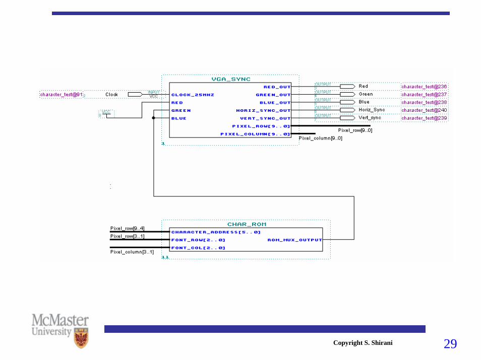
Character Test Design Example

30Copyright S. Shirani
Character Display (UP3)
COMPONENT char_romPORT(character_address : IN STD_LOGIC_VECTOR(5 downto 0);
font_row, font_col :IN STD_LOGIC_VECTOR(2 downto 0);rom_mux_output : OUT STD_LOGIC);
END COMPONENT;
Char_ROM
inst
clockclock
character_address[5..0]character_address[5..0]
font_row[2..0]font_row[2..0]
font_col[2..0]font_col[2..0]
rom_mux_outputrom_mux_output

31Copyright S. Shirani
Character Display (UP3)• Compared to UP2, UP3 char_ROM has one extra input.• This extra input (clock) should be tied to the video
pixel_clock

32Copyright S. Shirani
Character Display (UP3)
VCCClock_48Mhz INPUT VGA_RedOUTPUT
VGA_GreenOUTPUT
VGA_HSyncOUTPUT
VGA_VSyncOUTPUT
VGA_BlueOUTPUT
clock_48Mhz
red
green
blue
red_out
green_out
blue_out
horiz_sync_out
vert_sync_out
video_on
pixel_clock
pixel_row[9..0]
pixel_column[9..0]
VGA_SYNC
1
clock
character_address[5..0]
font_row[2..0]
font_col[2..0]
rom_mux_output
Char_ROM
inst
VCC
Pixel_column[9..0]
Pixel_row[9..0]
Pixel_row[9..4]
Pixel_row[3..1]
Pixel_column[3..1]

33Copyright S. Shirani
LCD display• LCD_Display core is used to display static ASCII characters and changing
hex values from the hardware on the UP3 LCD display• LCD_Display: 2 lines, up to 16 Characters on each• LCD_Display’s VHDL code can be modified by the user to display
different ASCII strings and hex data fields.
COMPONENT LCD_DisplayPORT(Hex_Display_Data; : IN
STD_LOGIC_VECTOR((Num_Hex_Digits*4)-1 DOWNTO 0);reset, clock_48Mhz: IN STD_LOGIC;LCD_RS, LCD_E : OUT STD_LOGIC;LCD_RW : INOUT STD_LOGIC;DATA_BUS: INOUT STD_LOGIC_VECTOR(7 DOWNTO 0));
END COMPONENT;

34Copyright S. Shirani
LCD display• Num_Hex_Digits is a Generic. • Set Num_Hex_Digits to the number of “live” hex digit data
values to be displayed (do not count ASCII character constants)
• In the VHDL source code of LCD_Display there is a LCD_display_string
• LCD_display_string is an ASCII character string entered in hex for the two lines of the LCD Display
• Edit LCD_display_string entries in LCD_Display.vhd to modify display
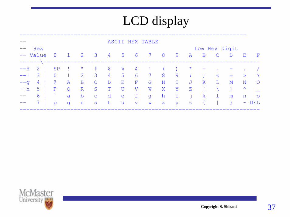
• Enter the ASCII character's 2 hex digit equivalent value (see table for ASCII hex values)

35Copyright S. Shirani
LCD display• To display character assign ASCII value to LCD_display_string• To skip a character use X"20" (ASCII space)• To display a "live" hex digit using values from hardware on LCD do the
following: make array element for that character location X"0" & 4-bit field from Hex_Display_Data.
• State machine in LCD_Display.vhd sees X"0" in high 4-bits & grabs the next lower 4-bits from Hex_Display_Data input and performs 4-bit binary to ASCII conversion needed to print a hex digit
• Num_Hex_Digits must be set to the count of hex data characters in the display
• Connect hardware bits to be displayed to Hex_Display_Data input• To display less than 32 characters, terminate string with an entry of X"FE"

36Copyright S. Shirani
LCD display• Example: LCD DISPLAYS THE FOLLOWING (D and DD are live
values):Row=DD Col=DD Mouse Lb=D Rb=D
• LCD_Display has to be modified as follows:-- Line 1X"52",X"6F",X"77",X"3D",X"0" & Hex_Display_Data(23 DOWNTO 20),X"0" & Hex_Display_Data(19 DOWNTO 16),X"20",X"43",X"6F",X"6C",X"3D",X"0" & Hex_Display_Data(15 DOWNTO 12),X"0" & Hex_Display_Data(11 DOWNTO 8),X"20",X"20",X"20",
-- Line 2X"4D",X"6F",X"75",X"73",X"65",X"20",X"4C",X"42",X"3D",X"0" & Hex_Display_Data(7 DOWNTO 4),X"20",X"52",X"42",X"3D",X"0" & Hex_Display_Data(3 DOWNTO 0),X"20");
37Copyright S. Shirani
LCD display--------------------------------------------------------------------- ASCII HEX TABLE-- Hex Low Hex Digit-- Value 0 1 2 3 4 5 6 7 8 9 A B C D E F------\------------------------------------------------------------------H 2 | SP ! " # $ % & ' ( ) * + , - . /--i 3 | 0 1 2 3 4 5 6 7 8 9 : ; < = > ?--g 4 | @ A B C D E F G H I J K L M N O--h 5 | P Q R S T U V W X Y Z [ \ ] ^ _-- 6 | ` a b c d e f g h i j k l m n o-- 7 | p q r s t u v w x y z { | } ~ DEL-----------------------------------------------------------------------
38Copyright S. Shirani
Interfacing to the PS/2 keyboard• Altra UP2 and UP3 supports the use of either a mouse or
keyboard using the PS/2 connector on the board• The connector provides electrical connection between the
keyboard/mouse and the board• It is necessary to design a hardware interface using FLEX or
Cyclone to communication with a keyboard or mouse.• UPcore library has the required VHDL codes for a keyboard
interface (keyboard.vhd) and mouse interface (mouse.vhd)

39Copyright S. Shirani
Keyboard scan codes• Keyboards are normally encoded by placing the key switches
in a matrix of rows and columns• All rows and columns are periodically scanned to find any
key state changes. • Key data is passed serially to the computer from the keyboard
using scan code.• Each key has a unique scan code based on the key switch
matrix row and column address

40Copyright S. Shirani
Keyboard scan codes• Scan code consists of Make and Break codes.• One make code is sent every time a key is pressed• When several keys are hit at the same time several make
codes are sent (this happens in fast typing and in using shift and ctrl)
• When a key is released, a break code is sent.• By using this break code if several keys are pressed at the
same time it can be distinguished which one was released• If a key is held down, the make code is continuously sent at
typematic (autorepeat) rate.

41Copyright S. Shirani
ESC110
F1112
F2113
F3114
F4115
F5116
F6117
F7118
F8119
F9120
F10121
F11122
F12123
PrintScrn124
Pause126
ScrollLock125
~ `1
! 12
@ 23
# 34
$ 45
% 56
^ 67
& 78
* 89
( 910
) 011
- _12
= +13
Backspace15
Tab16
Q17
W18
E19
R20
T21
Y22
U23
I24
O25
P26
[ {27
] }28
\ |29
Caps Lock30
A31
S32
D33
F34
G35
H36
J37
K38
L39
; :40
‘ “41
Enter43
Z31
X32
C33
V34
B35
N36
M37
, <38
. >39
/ ?40
Shift57
Shift44
Ctrl58
Ctrl64
Alt62
Alt60 61
Insert75
Home80
Del76
End81
Pg Up85
Pg Dn86
83
79 84 89
/95
*100
-105
896
+
106476
597
6102
298
0 Ins99
. Del104
NumLock90
7Home
91
9Pg Up101
1End93
3Pg Dn103
Enter
108
Key Numbers for Scan Code.

42Copyright S. Shirani
Table 10.3 Scan Codes for PS/2 Keyboard.
Key# Make Code
Break Code Key# Make
Code Break Code Key# Make
Code Break Code
1 0E F0 0E 31 1C F0 1C 90 77 F0 77 2 16 F0 16 32 1B F0 1B 91 6C F0 6C 3 1E F0 1E 33 23 F0 23 92 6B F0 6B 4 26 F0 26 34 2B F0 2B 93 69 F0 69 5 25 F0 25 35 34 F0 34 96 75 F0 75 6 2E F0 2E 36 33 F0 33 97 73 F0 73 7 36 F0 36 37 3B F0 3B 98 72 F0 72 8 3D F0 3D 38 42 F0 42 99 70 F0 70 9 3E F0 3E 39 4B F0 4B 100 7C F0 7C
10 46 F0 46 40 4C F0 4C 101 7D F0 7D 11 45 F0 45 41 52 F0 52 102 74 F0 74 12 4E F0 4E 43 5A F0 5A 103 7A F0 7A 13 55 F0 55 44 12 F0 12 104 71 F0 71 15 66 F0 66 46 1A F0 1A 105 7B F0 7B 16 0D F0 0D 47 22 F0 22 106 79 F0 79 17 15 F0 15 48 21 F0 21 110 76 F0 76 18 1D F0 1D 49 2A F0 2A 112 05 F0 05 19 24 F0 24 50 32 F0 32 113 06 F0 06 20 2D F0 2P 51 31 F0 31 114 04 F0 04 21 2C F0 2C 52 3A F0 3A 115 0c F0 0C 22 35 F0 35 53 41 F0 41 116 03 F0 03 23 3C F0 3C 54 49 F0 49 117 0B F0 0B 24 43 F0 43 55 4A F0 4A 118 83 F0 83 25 44 F0 44 57 59 F0 59 119 0A F0 0A 26 4D F0 4D 58 14 F0 14 120 01 F0 01 27 54 F0 54 60 11 F0 11 121 09 F0 09 28 5B F0 5B 61 29 F0 29 122 78 F0 78 29 5D F0 5D 62 E0 11 E0 F0 11 123 07 F0 07
The remaining key codes are a function of the shift, control, alt, or num-lock keys.

43Copyright S. Shirani
Table 10.3 (Continued) - Scan Codes for PS/2 Keyboard.
Key No Shift or Num Lock Shift* Num Lock On
# Make Break Make Break Make Break 76 E0 70 E0 F0 70 E0 F0 12 E0 70 E0 F0 70 E0 12 E0 12 E0 70 E0 F0 70 E0 F0 12 76 E0 71 E0 F0 71 E0 F0 12 E0 71 E0 F0 71 E0 12 E0 12 E0 71 E0 F0 71 E0 T0 12 79 E0 6B E0 F0 6B E0 F0 12 E0 6B E0 F0 6B E0 12 E0 12 E0 6B E0 F0 6B E0 F0 12 80 E0 6C E0 F0 6C E0 F0 12 E0 6C E0 F0 6C E0 12 E0 12 E0 6C E0 F0 6C E0 F0 12 81 E0 69 E0 F0 69 E0 F0 12 E0 69 E0 F0 69 E0 12 E0 12 E0 69 E0 F0 69 E0 F0 12 83 E0 75 E0 F0 75 E0 F0 12 E0 75 E0 F0 75 E0 12 E0 12 E0 75 E0 F0 75 E0 F0 12 84 E0 72 E0 F0 72 E0 F0 12 E0 72 E0 F0 72 E0 12 E0 12 E0 72 E0 F0 72 E0 F0 12 85 E0 7D E0 F0 7D E0 F0 12 E0 7D E0 F0 7D E0 12 E0 12 E0 7D E0 F0 7D E0 F0 12 86 E0 7A E0 F0 7A E0 F0 12 E0 7A E0 F0 7A E0 12 E0 12 E0 7A E0 F0 7A E0 F0 12 89 E0 74 E0 F0 74 E0 F0 12 E0 74 E0 F0 74 E0 12 E0 12 E0 74 E0 F0 74 E0 F0 12
* When the left Shift Key is held down, the 12 - FO 12 shift make and break is sent with the other scan codes. When the right Shift Key is held down, 59 – FO 59 is sent.
Key Scan Code Shift Case *
# Make Break Make Break 95 E0 4A E0 F0 4A E0 F0 12 E0 4A E0 12 F0 4A
* When the left Shift Key is held down, the 12 - FO 12 shift make and break is sent with the other scan codes. When the right Shift Key is held down, 59 - FO 59 is sent. When both Shift Keys are down, both sets of codes are sent with the other scan codes.
Key Scan Code Control Case, Shift Case Alt Case
# Make Break Make Break Make Break 124 E0 12 E0 7C E0 F0 7C E0 F0 I2 E0 7C E0 F0 7C 84 F0 84
Key # Make Code Control Key Pressed 126 * El 14 77 El F0 14 F0 77 E0 7E E0 F0 7E
* This key does not repeat

44Copyright S. Shirani
UP2 Keyboard function• UP2core library has a VHDL code that reads the scan code
bytes for the keyboard• keyboard.vhd has five inputs and two outputs:• Inputs:
– keyboard_clk: connected to keyboard clock pin – keyboard_data: connected to keyboard data pin – clock_25Mhz: connected to UP2 clock pin– reset: clears the internal registers and buffers– read: a handshaking signal. It’s rising edge clears the scan_ready
signal• Outputs:
– scan_code: scan code of the key pressed – scan_ready: is high when the scan code is ready.

45Copyright S. Shirani
COMPONENT keyboardPORT(keyboard_clk, keyboard_data, clock_25Mhz,
reset, read : IN STD_LOGIC;scan_code :OUT STD_LOGIC_VECTOR(7 downto 0);scan_ready : OUT STD_LOGIC);
END COMPONENT;

46Copyright S. Shirani
UP3 Keyboard function• UP3core library has a VHDL code that reads the scan code
bytes for the keyboard• keyboard.vhd has five inputs and two outputs:• Inputs:
– keyboard_clk: connected to keyboard clock pin – keyboard_data: connected to keyboard data pin – clock_48Mhz: connected to UP3 clock pin– reset: clears the internal registers and buffers– read: a handshaking signal. It’s rising edge clears the scan_ready
signal• Outputs:
– scan_code: scan code of the key pressed – scan_ready: is high when the scan code is ready.

47Copyright S. Shirani
COMPONENT keyboardPORT(keyboard_clk, keyboard_data, clock_48Mhz,
reset, read : IN STD_LOGIC;scan_code :OUT STD_LOGIC_VECTOR(7 downto 0);scan_ready : OUT STD_LOGIC);
END COMPONENT;
keyboard
inst
keyboard_clkkeyboard_clk
keyboard_datakeyboard_data
clock_48Mhzclock_48Mhz
resetreset
readread
scan_code[7..0]scan_code[7..0]
scan_readyscan_ready

48Copyright S. Shirani
Example design using the Keyboard UP2core.
49Copyright S. Shirani
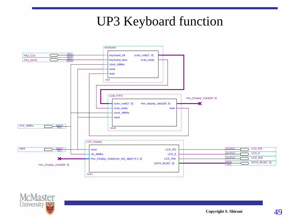
UP3 Keyboard function
VCCSW8 INPUT
VCCCLK_48Mhz INPUT
LCD_RSOUTPUT
LCD_EOUTPUT
LCD_RWOUTPUT
VCCDATA_BUS[7..0]BIDIR
VCCPS2_CLK BIDIRVCCPS2_DATA BIDIR
reset
clk_48Mhz
Hex_Display _Data[num_hex_digits*4-1..0]
LCD_RS
LCD_E
LCD_RW
DATA_BUS[7..0]
LCD_Display
inst1
scan_code[7..0]
scan_ready
clock_48Mhz
reset
Hex_display _data[39..0]
read
code_FIFO
inst3
key board_clk
key board_data
clock_48Mhz
reset
read
scan_code[7..0]
scan_ready
key board
inst
Hex_Display _Data[39..0]
Hex_Display _Data[39..0]

50Copyright S. Shirani

51Copyright S. Shirani
Symbol for MOUSE UP2core.

52Copyright S. Shirani
UP2 Mouse function• Inputs:
– clock_25Mhz: connected to UP2 clock pin– Reset: clears the internal registers and buffers
• Bi-directional data lines: – mouse_clk: connected to mouse clock pin – Mouse_data: connected to keyboard data pin
• Outputs: – left_button: high if the left button is pressed– right_button: high if the right button is pressed– mouse_cursor_row[9..0], mouse_cursor_column[9..0]: contain the
current address of the mouse cursor in 640x480 screen area

53Copyright S. Shirani
Example Design Using Mouse UP1core

54Copyright S. Shirani
UP3 Mouse function• Inputs:
– clock_48Mhz: connected to UP2 clock pin– Reset: clears the internal registers and buffers
• Bi-directional data lines: – mouse_clk: connected to mouse clock pin – Mouse_data: connected to keyboard data pin
• Outputs: – left_button: high if the left button is pressed– right_button: high if the right button is pressed– mouse_cursor_row[9..0], mouse_cursor_column[9..0]: contain the
current address of the mouse cursor in 640x480 screen area

55Copyright S. Shirani
VCCSW8 INPUT
VCCCLK_48Mhz INPUT
LCD_RSOUTPUT
LCD_EOUTPUT
LCD_RWOUTPUT
VCCDATA_BUS[7..0]BIDIR
VCCPS2_CLKBIDIR
VCCPS2_DATABIDIR
reset
clk_48Mhz
Hex_Display _Data[num_hex_digits*4-1..0]
LCD_RS
LCD_E
LCD_RW
DATA_BUS[7..0]
LCD_Display
inst
clock_48Mhz
reset
lef t_button
right_button
mouse_cursor_row[9..0]
mouse_cursor_column[9..0]
mouse_data
mouse_clk
MOUSE
inst1
mouse_cursor_row[9..0]
mouse_cursor_column[9..0]
lef t_button
right_button
Hex_Display _Data[23..0]
mouse_LCD_interf ace
inst3
lef t_button
right_button
right_buttonlef t_button
Top Related