


Languages
Pages
Legal


Posted 10/23/15 AM
516 8TH Avenue West PO Box 1209
Palmetto, Florida 34221 Phone (941)723-4570
Fax (941) 723-4576 Web: www.palmettofl.org
E-mail: [email protected]
Date: October 23, 2015 Re: Riverside Park Seawall Replacement
ADDENDUM #1 To All Plan Holders: Proposers are hereby notified that this addendum shall be made a part of the above-named solicitation and agreement documents. The item(s) listed below are issued to add to, modify, and clarify the solicitation and agreement documents. The item(s) shall have the same force and effect as the original solicitation and agreement documents. Quotes to be submitted shall conform to the addition and revision listed herein.
CLARIFICATION & ADDITIONAL INFORMATION
This project will require the Contractor to be a licensed Marine Contractor, not a General Contractor as listed in Part I – Item 4. Information regarding an acceptable alternate to the ESP panel specified on our plans is attached in two separate documents. Attachments: CMI Estimating Material Requirements CMI Sheet Piling Overview
END OF DOCUMENT
© 2011 Crane Materials International4501 Circle 75 Parkway, Suite E-5370 Atlanta, GA 30339 USA Phone 866-867-3762 Fax 770-933-8363 International 00+1+770+933+8166
Estimating Material Requirements
A CMI Technical White Paper
Ben Brown
Physical properties are defined by ASTM testing standards, The Aluminum Association Design Manual, The Naval Facilities Design Manual DM 7.2, The US Army Corps of Engineers General Design Guide: PVC Sheet Pile and/or standard engineering practice. The values shown are nominal and may vary. The information found in this document is believed to be true and accurate. No warranties of any kind are made as to the suitability of any CMI product for particular applications or the results obtained there from. Crane Materials International is a Crane Building Products® company. ShoreGuard®, The ShoreGuard Seawall SystemTM, C-Loc®, TimberGuard®, GeoGuard®, Dura Dock®, Shore-All®, GatorGates®, GatorDock EliteTM, ArmorWareTM, ArmorRodTM, Box ProfileTM, UltraCompositeTM, Elite WallTM, Elite PanelTM, Elite Fascia PanelTM, Flat PanelTM, XCRTM, XCR TechnologyTM, XCR VinylTM, GatorBridgeTM, Gator AluminumTM, Gator Sheet PilingTM, GatorDockTM, I-Beam LockTM, Textured SlateTM, Crane Materials InternationalTM logo, CMI Sheet Piling SolutionsTM, Aqua Terra SystemTM, EnduranceTM, Endurance CSPTM, PolarisTM, EclipseTM, GridSpineTM, 21 PolyTM, PileClawTM, SheerScapeTM, SheerScape Retaining Wall SystemsTM, Sheer PanelTM and CMI Waterfront SolutionsTM are trademarks, service marks or trade names of Crane Materials International. United States and International Patent numbers 4,674,921; 4,690,588; 5,292,208; 5,145,287; 6,000,883; 6,033,155; 6,053,666; D420,154; 6,575,667; 7,059,807; 7,056,066; 7,025,539; 7,393,482; 5,503,503; 5,803,672; 6,231,271; 1,245,061CA; 7,914,237 and other patents pending. © 2011 Crane Materials International. All Rights Reserved.
CRANE MATERIALS INTERNATIONAL

Estimating Material Requirements
© 2011 Crane Materials International4501 Circle 75 Parkway, Suite E-5370 Atlanta, GA 30339 USA Phone 866-730-9210 Fax 770-933-8363 International 00+1+770+933+8148
A seawall, like the foundation of a building, must be designed and constructed to handle very high loads and withstand numerous forces and environmental influences. A typical seawall is made up of sheet piling, and an anchor system (typically a wale beam, tie rods, and “dead-man” anchors).
All components must be made of materials designed to withstand the forces and environmental conditions expected. If any one component is overlooked, the system can fail. High performance seawall components are available in a number of colors and styles, and are produced in a wide range of strength capabilities.
Soil characteristics and other environmental conditions are the primary factors in determining sheet pile requirements. Using these properties and standard design methods, the wall’s designer will be able to specify sheet length and the required structural capacity of the sheet piling and anchor system components.
For the budgetary and comparison purposes of this exercise, CMI has evaluated several wall construction styles in typical soil conditions. These evaluations, in no way, represent the loading, soil, and/or site conditions for any particular project or location.
- WARNING -The following charts and tables list typical values for budgetary purposes only. Please rely on your engineer for specific design recommendations. Because of the complexity of geotechnical loading calculations and the susceptibility to extreme change of wall loads with minor changes in local site conditions such as soil parameters, water levels, and surcharge loads, etc., we strongly recommend the use of design professionals who are familiar with local wall construction to determine the required sheet piling and component capacity.
2

Estimating Material Requirements
© 2011 Crane Materials International4501 Circle 75 Parkway, Suite E-5370 Atlanta, GA 30339 USA Phone 866-730-9210 Fax 770-933-8363 International 00+1+770+933+8148
Before you begin:
Have in mind the architectural style the owner would like to achieve.
Long gone are the days when a seawall was built solely to retain earth. In the new sheet piling market, aesthetics often drive the structural decisions. A seawall is an investment. Much like a house, you have to live with this investment day in and day out. Choose the look that you want, and suitable components are available to fill that desire. A comprehensive sampling of color and architectural variations can be reviewed at www.cmiseawalls.com.
Determine the effective height of the wall (H).
Wall height (H) is defined as the distance from firm soil at the base of the wall to the top of the wall. This value will be used throughout the guide.
Determine the Linear Footage of the wall (L).
Linear Footage (L) is defined as the total length or distance along the shoreline the seawall is intended to protect.
Wall Height
3
Estimating Material Requirements
© 2011 Crane Materials International4501 Circle 75 Parkway, Suite E-5370 Atlanta, GA 30339 USA Phone 866-730-9210 Fax 770-933-8363 International 00+1+770+933+8148
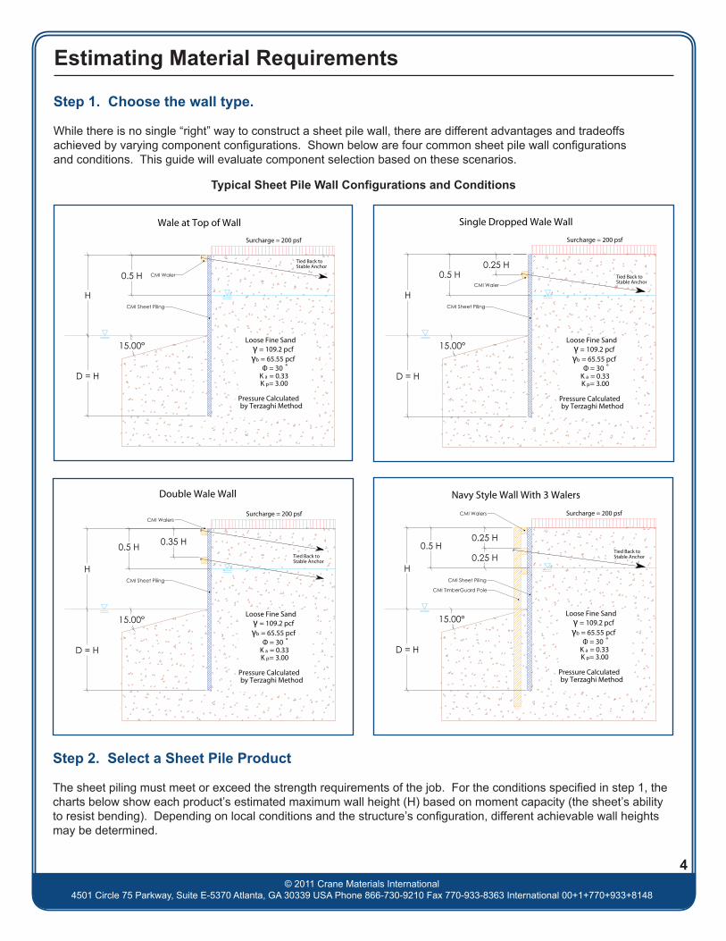
Step 1. Choose the wall type.
While there is no single “right” way to construct a sheet pile wall, there are different advantages and tradeoffs achieved by varying component configurations. Shown below are four common sheet pile wall configurations and conditions. This guide will evaluate component selection based on these scenarios.
Typical Sheet Pile Wall Configurations and Conditions
D = H
15.00°
H
0.5 H
Loose Fine Sandγ = 109.2 pcfγb = 65.55 pcf
Φ = 30 ˚K a = 0.33K p= 3.00
Pressure Calculated by Terzaghi Method
Surcharge = 200 psf
Wale at Top of Wall
Tied Back to Stable Anchor
CMI Sheet Piling
CMI Waler
D = H
15.00°
H
0.25 H0.5 H
Loose Fine Sandγ = 109.2 pcfγb = 65.55 pcf
Φ = 30 ˚K a = 0.33K p= 3.00
Pressure Calculated by Terzaghi Method
Surcharge = 200 psf
Single Dropped Wale Wall
Tied Back to Stable Anchor
CMI Sheet Piling
CMI Waler
D = H
15.00°
H
0.35 H0.5 H
Loose Fine Sandγ = 109.2 pcfγb = 65.55 pcf
Φ = 30 ˚K a = 0.33K p= 3.00
Pressure Calculated by Terzaghi Method
Surcharge = 200 psf
Double Wale Wall
Tied Back to Stable Anchor
CMI Sheet Piling
CMI Walers
H
D = H
15.00°
0.5 H0.25 H
0.25 H
Loose Fine Sandγ = 109.2 pcfγb = 65.55 pcf
Φ = 30 ˚K a = 0.33K p= 3.00
Pressure Calculated by Terzaghi Method
Surcharge = 200 psf
Navy Style Wall With 3 Walers
Tied Back to Stable Anchor
CMI Sheet Piling
CMI TimberGuard Pole
CMI Walers
4
Step 2. Select a Sheet Pile Product
The sheet piling must meet or exceed the strength requirements of the job. For the conditions specified in step 1, the charts below show each product’s estimated maximum wall height (H) based on moment capacity (the sheet’s ability to resist bending). Depending on local conditions and the structure’s configuration, different achievable wall heights may be determined.

3
4
5
6
7
8
9
10
11
12
13
14
15
16
17
18
19
20
21
Max
Wal
l Hei
ght (
�)
Top Wale
5
D = H
15.00°
H
0.5 H
Loose Fine Sandγ = 109.2 pcfγb = 65.55 pcf
Φ = 30 ˚K a = 0.33K p= 3.00
Pressure Calculated by Terzaghi Method
Surcharge = 200 psf
Wale at Top of Wall
Tied Back to Stable Anchor
CMI Sheet Piling
CMI Waler
The chart above is based on typical values, shown in step 1 of the Estimating Material Requirements guide published by CMI and each product’s rated bending moment capacity, for budgetary purposes only. Please rely on your engineer for specific minimum embedment depths, deflection checks and other design recommendations. Because of the complexity of geotechnical loading calculations and the susceptibility to extreme change of soil loads with minor changes in local site conditions such as soil parameters, water levels, surcharge loads, etc., we strongly recommend the use of design professionals who are familiar with local wall construction to determine the required sheet piling and component capacities. The bending moment contribution of face piles, where applicable, is neglected for the purposes of this exercise.
© 2011 Crane Materials International4501 Circle 75 Parkway, Suite E-5370 Atlanta, GA 30339 USA Phone 866-867-3762 Fax 770-933-8363 International 00+1+770+933+8166

6The chart above is based on typical values, shown in step 1 of the Estimating Material Requirements guide published by CMI and each product’s rated bending moment capacity, for budgetary purposes only. Please rely on your engineer for specific minimum embedment depths, deflection checks and other design recommendations. Because of the complexity of geotechnical loading calculations and the susceptibility to extreme change of soil loads with minor changes in local site conditions such as soil parameters, water levels, surcharge loads, etc., we strongly recommend the use of design professionals who are familiar with local wall construction to determine the required sheet piling and component capacities. The bending moment contribution of face piles, where applicable, is neglected for the purposes of this exercise.
© 2011 Crane Materials International4501 Circle 75 Parkway, Suite E-5370 Atlanta, GA 30339 USA Phone 866-867-3762 Fax 770-933-8363 International 00+1+770+933+8166
3
4
5
6
7
8
9
10
11
12
13
14
15
16
17
18
19
20
21
Max
Wal
l Hei
ght (
�)
Drop Wale
D = H
15.00°
H
0.25 H0.5 H
Loose Fine Sandγ = 109.2 pcfγb = 65.55 pcf
Φ = 30 ˚K a = 0.33K p= 3.00
Pressure Calculated by Terzaghi Method
Surcharge = 200 psf
Single Dropped Wale Wall
Tied Back to Stable Anchor
CMI Sheet Piling
CMI Waler

7The chart above is based on typical values, shown in step 1 of the Estimating Material Requirements guide published by CMI and each product’s rated bending moment capacity, for budgetary purposes only. Please rely on your engineer for specific minimum embedment depths, deflection checks and other design recommendations. Because of the complexity of geotechnical loading calculations and the susceptibility to extreme change of soil loads with minor changes in local site conditions such as soil parameters, water levels, surcharge loads, etc., we strongly recommend the use of design professionals who are familiar with local wall construction to determine the required sheet piling and component capacities. The bending moment contribution of face piles, where applicable, is neglected for the purposes of this exercise.
© 2011 Crane Materials International4501 Circle 75 Parkway, Suite E-5370 Atlanta, GA 30339 USA Phone 866-867-3762 Fax 770-933-8363 International 00+1+770+933+8166
3
4
5
6
7
8
9
10
11
12
13
14
15
16
17
18
19
20
21
Max
Wal
l Hei
ght (
�)
Double Wale
D = H
15.00°
H
0.35 H0.5 H
Loose Fine Sandγ = 109.2 pcfγb = 65.55 pcf
Φ = 30 ˚K a = 0.33K p= 3.00
Pressure Calculated by Terzaghi Method
Surcharge = 200 psf
Double Wale Wall
Tied Back to Stable Anchor
CMI Sheet Piling
CMI Walers

8The chart above is based on typical values, shown in step 1 of the Estimating Material Requirements guide published by CMI and each product’s rated bending moment capacity, for budgetary purposes only. Please rely on your engineer for specific minimum embedment depths, deflection checks and other design recommendations. Because of the complexity of geotechnical loading calculations and the susceptibility to extreme change of soil loads with minor changes in local site conditions such as soil parameters, water levels, surcharge loads, etc., we strongly recommend the use of design professionals who are familiar with local wall construction to determine the required sheet piling and component capacities. The bending moment contribution of face piles, where applicable, is neglected for the purposes of this exercise.
© 2011 Crane Materials International4501 Circle 75 Parkway, Suite E-5370 Atlanta, GA 30339 USA Phone 866-867-3762 Fax 770-933-8363 International 00+1+770+933+8166
3
4
5
6
7
8
9
10
11
12
13
14
15
16
17
18
19
20
21
Max
Wal
l Hei
ght (
�)
Navy Style
H
D = H
15.00°
0.5 H0.25 H
0.25 H
Loose Fine Sandγ = 109.2 pcfγb = 65.55 pcf
Φ = 30 ˚K a = 0.33K p= 3.00
Pressure Calculated by Terzaghi Method
Surcharge = 200 psf
Navy Style Wall With 3 Walers
Tied Back to Stable Anchor
CMI Sheet Piling
CMI TimberGuard Pole
CMI Walers
Estimating Material Requirements
© 2011 Crane Materials International4501 Circle 75 Parkway, Suite E-5370 Atlanta, GA 30339 USA Phone 866-730-9210 Fax 770-933-8363 International 00+1+770+933+8148
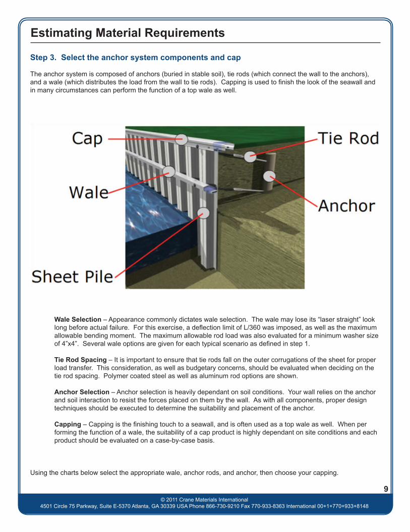
Step 3. Select the anchor system components and cap
The anchor system is composed of anchors (buried in stable soil), tie rods (which connect the wall to the anchors), and a wale (which distributes the load from the wall to tie rods). Capping is used to finish the look of the seawall and in many circumstances can perform the function of a top wale as well.
Wale Selection – Appearance commonly dictates wale selection. The wale may lose its “laser straight” look long before actual failure. For this exercise, a deflection limit of L/360 was imposed, as well as the maximum allowable bending moment. The maximum allowable rod load was also evaluated for a minimum washer size of 4”x4”. Several wale options are given for each typical scenario as defined in step 1.
Tie Rod Spacing – It is important to ensure that tie rods fall on the outer corrugations of the sheet for proper load transfer. This consideration, as well as budgetary concerns, should be evaluated when deciding on the tie rod spacing. Polymer coated steel as well as aluminum rod options are shown.
Anchor Selection – Anchor selection is heavily dependant on soil conditions. Your wall relies on the anchor and soil interaction to resist the forces placed on them by the wall. As with all components, proper design techniques should be executed to determine the suitability and placement of the anchor.
Capping – Capping is the finishing touch to a seawall, and is often used as a top wale as well. When per forming the function of a wale, the suitability of a cap product is highly dependant on site conditions and each product should be evaluated on a case-by-case basis.
Using the charts below select the appropriate wale, anchor rods, and anchor, then choose your capping.
9

Estimating Material Requirements
© 2011 Crane Materials International4501 Circle 75 Parkway, Suite E-5370 Atlanta, GA 30339 USA Phone 866-730-9210 Fax 770-933-8363 International 00+1+770+933+8148
10
Wale Rod Anchor Wale Rod Anchor Wale Rod Anchor Wale Rod Anchor
TG 4x6 TG 6x6 TG 6x6 TG 8x8AW-6 AW-6 AW-6 AW-6
UC-6 UC-6 UC-6 UC-6WB-2 AI 1 1/8 WB-2 AI 1 1/8 WB-2 AI 1 1/8 WB-2 AI 1 1/8
TG 6x6 TG 6x6 TG 8x8 TG 8x10AW-6 AW-6 AW-6 AW-6
UC-6 UC-6 UC-6 UC-6WB-2 AI 1 1/8 WB-2 AI 1 1/8 WB-2 AI 1 1/8 WB-2 AI 1 1/8
TG 6x6 TG 8x8 TG 8x8 TG 10x10AW-6 AW-6 AW-6 AW-6
UC-6 UC-6 UC-6 UC-6 STRWB-2 AI 1 1/8 WB-2 AI 1 1/8 WB-2 AI 1 1/8 WB-2 AI 1 1/8
TG 6x8 TG 8x8 TG 8x10 TG 10x12AW-6 AW-6 AW-6 AW-6 STR
UC-6 UC-6 UC-6WB-2 AI 1 1/8 WB-2 AI 1 1/8 WB-2 AI 1 1/8 WB-2 AI 1 1/8
TG 8x8 TG 8x10 TG 8x12 TG 12x12AW-6 AW-6 AW-6 AW-6 STR
UC-6 UC-6 UC-6WB-2 AI 1 1/8 WB-2 AI 1 1/8 WB-2 AI 1 1/8 WB-2 AI 1 1/8
TG 8x8 TG 8x12 TG 10x10 TG 12x12AW-6 AW-6 AW-6 STR
UC-6 UC-6 UC-6 STRWB-2 AI 1 1/8 WB-2 AI 1 1/8 WB-2 AI 1 1/8 WB-8 AI 1 1/4
TG 8x10 TG 10x10 TG 10x12AW-6 AW-6 STR AW-6 STR
UC-6 UC-6 STRWB-2 AI 1 1/8 WB-2 AI 1 1/8 WB-2 AI 1 1/8 WB-8 AI 1 1/2
TG 8x12 TG 10x10 TG 12x12AW-6 STR AW-6 STR
UC-6 STR UC-6 STRWB-2 AI 1 1/8 WB-2 AI 1 1/8 WB-2 AI 1 1/4
TG 8x12 TG 10x12 TG 12x12AW-6 STR
UC-6 STRWB-2 AI 1 1/8 WB-2 AI 1 1/4 WB-8 AI 1 1/2
TG 10x10 AW 1 TG 12x12 AW 1
WB-2 AI 1 1/4 WB-2 AI 1 1/2
TG 10x10 TG 12x12
WB-2 AI 1 1/4 WB-8 AI 1 1/2
TG 10x12 TG 12x12
WB-2 AI 1 1/2 AI 1 1/2
TG 12x12
WB-2 AI 1 1/2
TG 12x12
WB-2 AI 1 1/2
Wal
l Hei
ght (
�)
3 AW 3/4DMA-8
AW 3/4DMA-8
AW 3/4DMA-8
Wale at TopAnchor Rod Spacing (�)
4 5 6 8
AW 3/4DMA-8
AW 3/4
DMA-8AW 3/4
DMA-8AW 3/4
AW 1
DMA-8AW 3/4
DMA-84 AW 3/4DMA-8
AW 3/4DMA-8
AW 3/4
DMA-8AW 3/4
DMA-85 AW 3/4DMA-8
DMA-8AW 3/4
DMA-86 AW 3/4DMA-8
AW 3/4DMA-8
AW 3/4
DMA-8AW 1
DMA-87 AW 3/4
8 AW 3/4DMA-8
AW 3/4DMA-8
AW 3/4
9 AW 3/4DMA-8
AW 3/4DMA-8
AW 1
11 AW 1DMA-8
DMA-910 AW 3/4DMA-8
AW 1DMA-8
AW 1
13 DMA-9 DMA-12
12 DMA-9 DMA-12
15 DMA-12
14 DMA-12 DMA-12
16 DMA-12
DMA-8AW 1
DMA-9
AW 3/4DMA-8
AW 1
AW 1
AW 1DMA-12
AW 1DMA-12DMA-8
DMA-9
The charts above are based off typical values, shown in step 1, for budgetary purposes only. Please rely on your engineer for specific design recommendations. Because of the complexity of geotechnical loading calculations and the susceptibility to extreme change of soil loads with minor changes in local site conditions such as soil parameters, water levels, surcharge loads, etc., we strongly recommend the use of design professionals who are familiar with local wall construction to determine the required sheet piling and component capacities.

Estimating Material Requirements
© 2011 Crane Materials International4501 Circle 75 Parkway, Suite E-5370 Atlanta, GA 30339 USA Phone 866-730-9210 Fax 770-933-8363 International 00+1+770+933+8148
Wale Rod Anchor Wale Rod Anchor Wale Rod Anchor Wale Rod Anchor
TG 6x6 TG 6x6 TG 6x8 TG 8x8AW-6 AW-6 AW-6 AW-6
UC-6 UC-6 UC-6 UC-6WB-2 AI 1 1/8 WB-2 AI 1 1/8 WB-2 AI 1 1/8 WB-2 AI 1 1/8
TG 6x6 TG 6x8 TG 8x8 TG 8x10AW-6 AW-6 AW-6 AW-6
UC-6 UC-6 UC-6 UC-6WB-2 AI 1 1/8 WB-2 AI 1 1/8 WB-2 AI 1 1/8 WB-2 AI 1 1/8
TG 6x8 TG 8x8 TG 8x10 TG 10x10AW-6 AW-6 AW-6 AW-6
UC-6 UC-6 UC-6WB-2 AI 1 1/8 WB-2 AI 1 1/8 WB-2 AI 1 1/8 WB-2 AI 1 1/8
TG 8x8 TG 8x8 TG 8x12 TG 10x12AW-6 AW-6 AW-6 AW-6 STR
UC-6 UC-6 UC-6WB-2 AI 1 1/8 WB-2 AI 1 1/8 WB-2 AI 1 1/8 WB-2 AI 1 1/8
TG 8x8 TG 8x10 TG 10x10 TG 12x12AW-6 AW-6 AW-6 STR
UC-6 UC-6 UC-6 STRWB-2 AI 1 1/8 WB-2 AI 1 1/8 WB-2 AI 1 1/8 WB-8 AI 1 1/8
TG 8x10 TG 10x10 TG 10x12AW-6 AW-6 STR AW-6 STR
UC-6 UC-6 STR UC-6 STRWB-2 AI 1 1/8 WB-2 AI 1 1/8 WB-2 AI 1 1/8 WB-8 AI 1 1/4
TG 8x10 TG 10x10 TG 12x12AW-6 STR AW-6 STR
UC-6 UC-6 STRWB-2 AI 1 1/8 WB-2 AI 1 1/8 WB-2 AI 1 1/4
TG 8x12 TG 10x12 TG 12x12AW-6 STR
UC-6 STRWB-2 AI 1 1/8 WB-2 AI 1 1/4 WB-8 AI 1 1/2
TG 10x10 TG 12x12
UC-6 STRWB-2 AI 1 1/4 WB-2 AI 1 1/2
TG 10x10 TG 12x12
UC-6 STRWB-2 AI 1 1/4 WB-8 AI 1 1/2
TG 10x12 TG 12x12
WB-2 AI 1 1/2 AI 1 1/2
TG 12x12
WB-2 AI 1 1/2
TG 12x12
AI 1 3/4
TG 12x12
AI 1 3/4
6 8
4
Wal
l Hei
ght (
�)
3
5
6
7
10
15
16
8
AW 3/4
AW 3/4
AW 19
DMA-16
DMA-16
DMA-9
DMA-12
DMA-12
DMA-12
AW 3/4
AW 1
AW 1
AW 1
AW 1
AW 3/4DMA-8 DMA-8 DMA-8
DMA-8
DMA-8
DMA-8
DMA-8
DMA-8
DMA-8
DMA-8
DMA-8
DMA-8
DMA-8
DMA-8
DMA-9
AW 3/4
AW 3/4
AW 3/4
AW 3/4
AW 1
AW 1
DMA-12
DMA-8
DMA-8
13
14
DMA-8
DMA-8
DMA-8
DMA-8
DMA-9
DMA-9
DMA-12
DMA-12
AW 1
AW 1
AW 3/4
AW 3/4
AW 3/4
AW 1
AW 1
AW 1
54Anchor Rod Spacing (�)Single
Dropped Wale
11
12
DMA-8
DMA-8
DMA-8
DMA-8 DMA-8
DMA-8
DMA-9
AW 3/4
AW 3/4
AW 3/4
AW 3/4
AW 3/4
AW 3/4
AW 3/4
AW 3/4
AW 3/4
AW 3/4
AW 3/4
11
The charts above are based off typical values, shown in step 1, for budgetary purposes only. Please rely on your engineer for specific design recommendations. Because of the complexity of geotechnical loading calculations and the susceptibility to extreme change of soil loads with minor changes in local site conditions such as soil parameters, water levels, surcharge loads, etc., we strongly recommend the use of design professionals who are familiar with local wall construction to determine the required sheet piling and component capacities.

Estimating Material Requirements
© 2011 Crane Materials International4501 Circle 75 Parkway, Suite E-5370 Atlanta, GA 30339 USA Phone 866-730-9210 Fax 770-933-8363 International 00+1+770+933+8148
The charts above are based off typical values, shown in step 1, for budgetary purposes only. Please rely on your engineer for specific design recommendations. Because of the complexity of geotechnical loading calculations and the susceptibility to extreme change of soil loads with minor changes in local site conditions such as soil parameters, water levels, surcharge loads, etc., we strongly recommend the use of design professionals who are familiar with local wall construction to determine the required sheet piling and component capacities.
12
Wale Rod Anchor Wale Rod Anchor Wale Rod Anchor Wale Rod Anchor
TG 6x6 TG 6x6 TG 8x8 TG 8x10AW-6 AW-6 AW-6 AW-6UC-6 UC-6 UC-6 UC-6WB-2 AI 1 1/8 WB-2 AI 1 1/8 WB-2 AI 1 1/8 WB-2 AI 1 1/8
TG 6x6 TG 8x8 TG 8x8 TG 10x10AW-6 AW-6 AW-6 AW-6UC-6 UC-6 UC-6 UC-6 STRWB-2 AI 1 1/8 WB-2 AI 1 1/8 WB-2 AI 1 1/8 WB-2 AI 1 1/8
TG 6x8 TG 8x8 TG 8x10 TG 10x12AW-6 AW-6 AW-6 AW-6 STRUC-6 UC-6 UC-6WB-2 AI 1 1/8 WB-2 AI 1 1/8 WB-2 AI 1 1/8 WB-2 AI 1 1/8
TG 8x8 TG 8x10 TG 10x10 TG 12x12AW-6 AW-6 AW-6UC-6 UC-6 UC-6WB-2 AI 1 1/8 WB-2 AI 1 1/8 WB-2 AI 1 1/8 WB-2 AI 1 1/8
TG 8x8 TG 8x12 TG 10x10 TG 12x12AW-6 AW-6 AW-6 STRUC-6 UC-6 UC-6 STRWB-2 AI 1 1/8 WB-2 AI 1 1/8 WB-2 AI 1 1/8 WB-8 AI 1 1/4
TG 8x10 TG 10x10 TG 10x12AW-6 AW-6 STR AW-6 STRUC-6 UC-6 STRWB-2 AI 1 1/8 WB-2 AI 1 1/8 WB-2 AI 1 1/8 WB-8 AI 1 1/2
TG 8x12 TG 10x10 TG 12x12AW-6 STR AW-6 STRUC-6 STR UC-6 STR
WB-2 AI 1 1/8 WB-2 AI 1 1/8 WB-2 AI 1 1/4
TG 8x12 TG 10x12 TG 12x12AW-6 STRUC-6 STR
WB-2 AI 1 1/8 WB-2 AI 1 1/4 WB-8 AI 1 1/2
TG 10x10 TG 12x12
WB-2 AI 1 1/4 WB-2 AI 1 1/2
TG 10x12 AW 1 TG 12x12
WB-2 AI 1 1/4 WB-8 AI 1 1/2
TG 10x12
WB-2 AI 1 1/2
TG 12x12
WB-2 AI 1 1/2
TG 12x12
AI 1 3/4
TG 12x12
AI 1 3/4
9 AW 3/4DMA-8
AW 1DMA-8
AW 1DMA-8
AW 1DMA-12
AW 3/48
15 DMA-12
16 DMA-16
17
Wal
l Hei
ght (
�)
12 AW 1DMA-9
AW 1DMA-12
13 DMA-9 DMA-12
14 AW 1DMA-12
10 AW 3/4DMA-8
AW 1DMA-8
AW 1DMA-9
11 AW 1DMA-8
AW 1DMA-9
AW 1DMA-12
DMA-8AW 3/4
DMA-8AW 3/4
DMA-8AW 1
DMA-9
7 AW 3/4DMA-8
AW 3/4DMA-8
AW 3/4DMA-8
AW 1DMA-8
6 AW 3/4DMA-8
AW 3/4DMA-8
AW 3/4DMA-8
AW 3/4DMA-8
5 AW 3/4DMA-8
AW 3/4
AW 3/4DMA-8
AW 3/4DMA-8
DMA-8AW 3/4
DMA-8AW 3/4
DMA-8
Double WaleAnchor Rod Spacing (�)
4 5 6 8
4 AW 3/4DMA-8
AW 3/4DMA-8

Estimating Material Requirements
© 2011 Crane Materials International4501 Circle 75 Parkway, Suite E-5370 Atlanta, GA 30339 USA Phone 866-730-9210 Fax 770-933-8363 International 00+1+770+933+8148
Wale Rod Anchor Wale Rod Anchor Wale Rod Anchor Wale Rod Anchor
TG 6x6 TG 6x8 TG 8x8 TG 8x12AW-6 AW-6 AW-6 AW-6UC-6 UC-6 UC-6 UC-6WB-2 AI 1 1/8 WB-2 AI 1 1/8 WB-2 AI 1 1/8 WB-2 AI 1 1/8
TG 6x8 TG 8x8 TG 8x10 TG 10x10AW-6 AW-6 AW-6 AW-6UC-6 UC-6 UC-6WB-2 AI 1 1/8 WB-2 AI 1 1/8 WB-2 AI 1 1/8 WB-2 AI 1 1/8
TG 8x8 TG 8x8 TG 8x12 TG 10x12AW-6 AW-6 AW-6 AW-6 STRUC-6 UC-6 UC-6 STRWB-2 AI 1 1/8 WB-2 AI 1 1/8 WB-2 AI 1 1/8 WB-2 AI 1 1/4
TG 8x8 TG 8x10 TG 10x10 TG 12x12AW-6 AW-6 AW-6 STRUC-6 UC-6 STR UC-6 STRWB-2 AI 1 1/8 WB-2 AI 1 1/8 WB-2 AI 1 1/4 WB-8 AI 1 1/2
TG 8x8 TG 8x12 TG 10x12AW-6 AW-6 STR AW-6 STR
UC-6 STRWB-2 AI 1 1/8 WB-2 AI 1 1/4 WB-2 AI 1 1/4
TG 8x10 TG 10x10 TG 12x12AW-6 STR AW-6 STRUC-6 STR
WB-2 AI 1 1/8 WB-2 AI 1 1/4 WB-2 AI 1 1/2
TG 8x12 TG 10x10 TG 12x12AW-6 STR
WB-2 AI 1 1/4 WB-2 AI 1 1/2 WB-8 AI 1 1/2
TG 10x10 TG 10x12AW-6 STR
WB-2 AI 1 1/2 WB-2 AI 1 1/2
TG 10x10 TG 12x12
WB-2 AI 1 1/2 WB-2 AI 1 3/4
TG 10x12 TG 12x12
WB-2 AI 1 3/4 AI 1 3/4
TG 10x12
WB-2 AI 1 3/4
TG 12x12
WB-2 AI 1 3/4
TG 12x12
AI 2
TG 12x12
AI 2
DMA-20
DMA-16
17 DMA-20
DMA-16 DMA-16
15 DMA-16
DMA-12
13 DMA-12 DMA-16
12 AW 1DMA-12
11 AW 1DMA-9
10 AW 1
DMA-9AW 1
Anchor Rod Spacing (�)4 5 6 8
5 AW 3/4DMA-8
AW 3/4DMA-8
AW 3/4DMA-8
AW 3/4DMA-8
AW 1DMA-12
Wal
Hei
ght (
�)
9 AW 1DMA-8 DMA-9
DMA-8AW 1
DMA-9 DMA-12
DMA-12 DMA-12
AW 1
DMA-9
8 AW 3/4DMA-8
AW 1DMA-8
AW 1
AW 3/4DMA-8
AW 3/4DMA-8
AW 3/4DMA-8
AW 1DMA-8
7 AW 3/4DMA-8
AW 3/4DMA-8
AW 3/4DMA-8
AW 1
DMA-9
Navy Wall
6
14
16
18
13
The charts above are based off typical values, shown in step 1, for budgetary purposes only. Please rely on your engineer for specific design recommendations. Because of the complexity of geotechnical loading calculations and the susceptibility to extreme change of soil loads with minor changes in local site conditions such as soil parameters, water levels, surcharge loads, etc., we strongly recommend the use of design professionals who are familiar with local wall construction to determine the required sheet piling and component capacities.

Estimating Material Requirements
© 2011 Crane Materials International4501 Circle 75 Parkway, Suite E-5370 Atlanta, GA 30339 USA Phone 866-730-9210 Fax 770-933-8363 International 00+1+770+933+8148
The time and expense of being short on materials can be crippling. Most contractors add around 3%-5% onto materi-als (rounded up) to account for the unknown and potential errors in the field.
14
SheetUC-95 AW-1900 UC-2400
UC-75 AW-1600 UC-1800
PZH-159 SC-15
PZH-153 SC-15
UC-50 AW-1075 AW-1075 STR
SG-950 AW-1500
PZH-7 SC-13
PZH-3 SC-13
UC-30 AW-850 AW-850 STR AW-855 AW-855 STR
PZH-1 SC-13
SG-750 AW-1075 AW-1075 STR
FP-575 AW-1075 AW-1075 STR
SG-650 AW-1075 AW-1075 STR
PZM-19 SC-9
SG-625 AW-1075 AW-1075 STR
PZM-16 SC-9
FP-475 AW-850 AW-850 STR AW-855 AW-855 STR
CL-9900 AW-1075 AW-1075 STR
SG-550 AW-850 AW-850 STR AW-855 AW-855 STR
UC-20 AW-575 AW-575 STR
SG-525 AW-1075 AW-1075 STR
AWM-8 SC-9
CL-9000 AW-1075 AW-1075 STR
SG-425 AW-850 AW-850 STR AW-855 AW-855 STR
AWM-3 SC-9
SG-300 AW-850 AW-850 STR AW-855 AW-855 STR
SG-325 AW-850 AW-850 STR AW-855 AW-855 STR
AWL-8 SC-7
AWL-3 SC-7
SG225 AW-575 AW-575 STR
CL-4500 AW-575 AW-575 STR
Compa�ble Caps
Estimating Material Requirements
© 2011 Crane Materials International4501 Circle 75 Parkway, Suite E-5370 Atlanta, GA 30339 USA Phone 866-730-9210 Fax 770-933-8363 International 00+1+770+933+8148
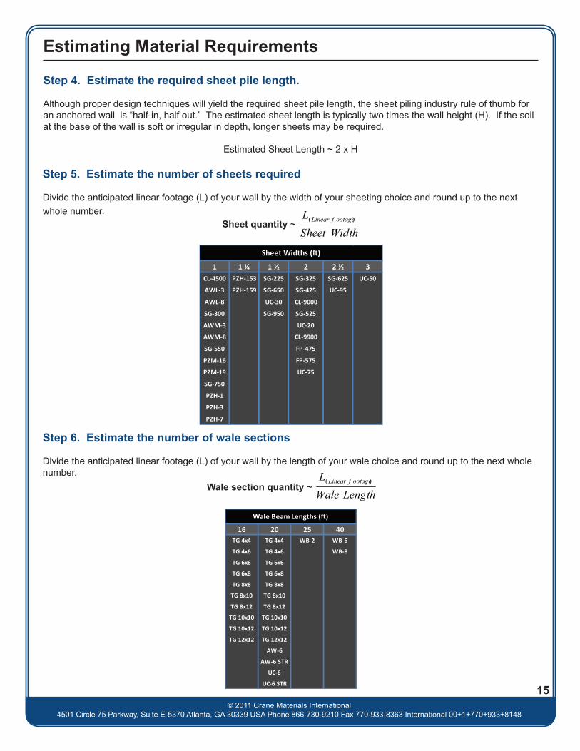
Step 5. Estimate the number of sheets required
Divide the anticipated linear footage (L) of your wall by the width of your sheeting choice and round up to the next whole number.
Sheet quantity ~
Step 6. Estimate the number of wale sections
Divide the anticipated linear footage (L) of your wall by the length of your wale choice and round up to the next whole number.
Wale section quantity ~
15
1 1 ¼ 1 ½ 2 2 ½ 3CL-4500 PZH-153 SG-225 SG-325 SG-625 UC-50
AWL-3 PZH-159 SG-650 SG-425 UC-95
AWL-8 UC-30 CL-9000
SG-300 SG-950 SG-525
AWM-3 UC-20
AWM-8 CL-9900
SG-550 FP-475
PZM-16 FP-575
PZM-19 UC-75
SG-750
PZH-1
PZH-3
PZH-7
Sheet Widths (�)
16 20 25 40TG 4x4 TG 4x4 WB-2 WB-6
TG 4x6 TG 4x6 WB-8
TG 6x6 TG 6x6
TG 6x8 TG 6x8
TG 8x8 TG 8x8
TG 8x10 TG 8x10
TG 8x12 TG 8x12
TG 10x10 TG 10x10
TG 10x12 TG 10x12
TG 12x12 TG 12x12
AW-6
AW-6 STR
UC-6
UC-6 STR
Wale Beam Lengths (�)
Step 4. Estimate the required sheet pile length.
Although proper design techniques will yield the required sheet pile length, the sheet piling industry rule of thumb for an anchored wall is “half-in, half out.” The estimated sheet length is typically two times the wall height (H). If the soil at the base of the wall is soft or irregular in depth, longer sheets may be required.
Estimated Sheet Length ~ 2 x H
Estimating Material Requirements
© 2011 Crane Materials International4501 Circle 75 Parkway, Suite E-5370 Atlanta, GA 30339 USA Phone 866-730-9210 Fax 770-933-8363 International 00+1+770+933+8148
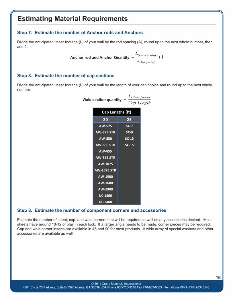
Step 7. Estimate the number of Anchor rods and Anchors
Divide the anticipated linear footage (L) of your wall by the rod spacing (A), round up to the next whole number, then add 1.
Step 8. Estimate the number of cap sections
Divide the anticipated linear footage (L) of your wall by the length of your cap choice and round up to the next whole number.
Anchor rod and Anchor Quantity ~
Wale section quantity ~
Step 8. Estimate the number of component corners and accessories
Estimate the number of sheet, cap, and wale corners that will be required as well as any accessories desired. Most sheets have around 10-12 of play in each lock. If a larger angle needs to be made, corner pieces may be required. Cap and wale corner inserts are available in 45 and 90 for most products. A wide array of special washers and other accessories are available as well.
16
20 25AW-575 SC-7
AW-575 STR SC-9
AW-850 SC-13
AW-850 STR SC-15
AW-855
AW-855 STR
AW-1075
AW-1075 STR
AW-1500
AW-1600
AW-1900
UC-1800
UC-2400
Cap Lengths (�)

© 2011 Crane Materials International4501 Circle 75 Parkway, Suite E-5370 Atlanta, GA 30339 USA Phone 866-867-3762 Fax 770-933-8363 International 00+1+770+933+8166
Material Estimating Worksheet
Gather Preliminary Information
What is the wall height (H)?
Anticipated Linear footage (L)?
Choose your Components
From Step 1. What type of wall will you be building?
From Step 2. What sheet did you choose?
From Step 3. What rod spacing (A) did you choose? What Wale option did you choose?
What anchor rod did you choose?
What anchor did you choose?
What capping option did you choose?
Determining Lengths and Quantities
From Step 4. Estimated sheet length
From Step 5. Sheet quantity
From Step 6. Wale quantity
From Step 7. Tie Rod/Anchor quantities
From Step 8. Cap quantity
From Step 9. Corners and other accessories
The time and expense of being short on materials can be crippling. Most contractors add around 3%-5% onto materials (rounded up) to account for the unknown and potential errors in the field.Contact your CMI representative 866-867-3762 for pricing, technical resources or experienced engineers serving your area.
17

© 2011 Crane Materials International4501 Circle 75 Parkway, Suite E-5370 Atlanta, GA 30339 USA Phone 866-867-3762 Fax 770-933-8363 International 00+1+770+933+8166
Material Estimating Worksheet Example
Gather Preliminary Information
What is the wall height (H)?
Anticipated Linear footage (L)?
Choose your Components
From Step 1. What type of wall will you be building?
From Step 2. What sheet did you choose?
From Step 3. What rod spacing (A) did you choose? What Wale option did you choose?
What anchor rod did you choose?
What anchor did you choose?
What capping option did you choose?
Determining Lengths and Quantities
From Step 4. Estimated sheet length
From Step 5. Sheet quantity
From Step 6. Wale quantity
From Step 7. Tie Rod/Anchor quantities
From Step 8. Cap quantity
From Step 9. Corners and other accessories
The time and expense of being short on materials can be crippling. Most contractors add around 3%-5% onto materials (rounded up) to account for the unknown and potential errors in the field.Contact your CMI representative 866-867-3762 for pricing, technical resources or experienced engineers serving your area.
18
I like the look of vinyl, and the box profile
CL 9900 is a 2’ wide sheet, so it needs to be divided by 2. I will use a TimberGuard wale so I would like it to divide into 16’ or 20
I want to keep the look and color similar to the sheet
2x7=14
635/2=317.5 318+10(3% buffer)=328
635/20=31.75 32+1(3% buffer)=33
635/4=158.75 159+1+5(3% buffer)=165
635/20=317.5 32+1(3% buffer)=33
328
14’
33
165
33
7’
635’
Wale at Top
CL 9900
4’
TG 8x8
AW-6 ¾”
DMA 8
AW1”075
SG 225-425 Corner (2), AW 1075 45” Corner Insert (2), Beveled PVC Washers (165)

Physical properties are defined by ASTM testing standards, The Aluminum Association Design Manual, The Naval Facilities Design Manual DM 7.2, The US Army Corps of Engineers General Design Guide: PVC Sheet Pile and/or standard engineering practice. The values shown are nominal and may vary. The information found in this document is believed to be true and accurate. No warranties of any kind are made as to the suitability of any CMI product for particular applications or the results obtained there from. Crane Materials International is a Crane Building Products® company. ShoreGuard®, The ShoreGuard Seawall SystemTM, C-Loc®, TimberGuard®, GeoGuard®, Dura Dock®, Shore-All®, GatorGates®, GatorDock EliteTM, ArmorWareTM, ArmorRodTM, Box ProfileTM, UltraCompositeTM, Elite WallTM, Elite PanelTM, Elite Fascia PanelTM, Flat PanelTM, XCRTM, XCR TechnologyTM, XCR VinylTM, GatorBridgeTM, Gator AluminumTM, Gator Sheet PilingTM, GatorDockTM, I-Beam LockTM, Textured SlateTM, Crane Materials InternationalTM logo, CMI Sheet Piling SolutionsTM, Aqua Terra SystemTM, EnduranceTM, Endurance CSPTM, PolarisTM, EclipseTM, GridSpineTM, 21 PolyTM, PileClawTM, SheerScapeTM, SheerScape Retaining Wall SystemsTM, Sheer PanelTM and CMI Waterfront SolutionsTM are trademarks, service marks or trade names of Crane Materials International. United States and International Patent numbers 4,674,921; 4,690,588; 5,292,208; 5,145,287; 6,000,883; 6,033,155; 6,053,666; D420,154; 6,575,667; 7,059,807; 7,056,066; 7,025,539; 7,393,482; 5,503,503; 5,803,672; 6,231,271; 1,245,061CA; 7,914,237 and other patents pending. © 2014 Crane Materials International. All Rights Reserved.
Updated November 1, 2014
Product Allowable Moment
(M) ft-lb/ft
Stiffness word (EI)
x106 lb-in2/ft
Section Modulus
(Z) in3/ft
Moment of Inertia (I)
in4/ft
Thickness Web/Flange
(t) in
Section Depth
(D) in
Section Width
(W) in
Material Profile
kN-m/m kN-m2/m cm3/m cm4/m mm mm mm
48,750 1,988 58.5 497 0.54 17 30216.84 18,717 3,145 67,870 13.7 432 762
31,667 1,064 38 266 0.400 / 0.430 14 24
140.85 10,018 2,043 36,325 10.2 / 10.9 356 610
27,625 850 17 85 0.220 / 0.270 10 15122.88 8,003 914 11,610 5.6 / 5.9 254 381
21,125 650 13 65 0.183 10 1593.96 6,120 699 8,876 4.6 254 381
17,333 416 20.8 104 0.325 / 0.355 10 3677.10 3,917 1,118 14,200 8.3 / 9.0 305 914
15,147 130 56.8 341 0.715 12 1867.37 1,220 3,054 46,567 18.1 152 457
14,625 270 9 27 0.245 6 1265.05 2,542 484 3,687 6.2 152 305
11,863 220 7.3 22 0.183 6 1252.77 2,071 393 3,004 4.6 203 305
10,833 208 13 52 0.250 / 0.265 8 1848.19 1,958 698 7,101 6.4 / 6.7 254 457
9,920 71 37.2 186 0.515 10 1844.12 665 2,000 25,400 13.1 152 457
9,787 84 36.7 220 0.485 12 3043.53 787 1,973 30,043 12.2 305 762
9,750 180 6 18 0.145 6 1243.37 1,695 323 2,458 3.7 229 305
8,320 35 31.2 91 0.29 9 2437.01 326 1,677 12,430 7.4 / 12.1 254 610
7,893 56 29.6 148 0.385 10 1835.11 530 1,591 20,212 9.8 102 457
6,663 82 4.1 8.2 0.170 / 0.183 4 1229.64 772 220 1,120 4.3 / 4.6 254 305
6,507 46 24.4 122 0.385 10 3028.94 437 1,312 16,660 9.8 102 762
5,850 71 3.6 7.1 0.140 / 0.155 4 1226.02 669 194 970 3.6 / 3.9 178 305
5,467 17 20.5 45 0.25 / 0.24 7 2424.32 161 1,102 6,145 6.4 / 6.1 178 610
5,333 34 20 90 0.35 9 2423.72 322 1,075 12,290 8.9 229 610
4,550 55 2.8 5.5 0.121 4 1220.24 518 151 751 3.1 102 305
4,320 28 16.2 73 0.28 9 2419.22 261 871 9,969 7.1 229 610
3,813 22 14.3 57 0.285 8 2416.96 204 769 7,784 7.2 203 610
3,575 44 2.2 4.4 0.095 4 1215.90 414 118 601 2.4 102 305
2,960 15 11.1 39 0.25 7 2413.17 140 597 5,326 6.4 178 610
2,275 17 1.4 1.7 0.11 2.5 1210.12 160 75 232 2.8 64 305
1,950 15 1.2 1.5 0.095 2.5 128.67 141 65 205 2.4 64 305
1,920 7 7.2 18 0.225 5 188.54 64 387 2,458 5.7 127 457
Aluminum Pan
Aluminum Pan
Vinyl Box
Vinyl Box
Aluminum Pan
Vinyl Box
Vinyl Box
Aluminum Pan
Vinyl Box
Vinyl Box
Aluminum Z
Vinyl Flat
Flat
Vinyl Z
Aluminum Z
FRP Composite
FRP Composite
Aluminum
Aluminum
FRP Composite
Vinyl
Aluminum
Aluminum
FRP Composite
Vinyl
Vinyl
Aluminum
Z
Z
Z
Z
Box
Z
Z
Z
Z
Z
Z
Vinyl
SG-225
PZM-16
FP-475
CL-9900
AWM-8
CL-9000
SG-425
AWM-3
SG-325
AWL-8
AWL-3
SG-625
UC-50
SG-950
PZH-7
PZH-3
UC-30
SG-850
SG-825
PZH-1
FP-575
SG-650
PZM-19
PZH-159
PZH-153
UC-95
UC-75
Sheet Piling Overview
Box
Top Related