


Languages
Pages
Legal


CHIP FERRITE BEADS
1. Effective for suppressing noise at high frequency, from several MHz to several hundreds MHz.2. Chip type is suited for preventing the abnormal oscillation in high frequency amplifying circuits.3. Terminal electrode has excellent solder heat resistance.4. Frequency Characteristics of the high impedance products for high performance electronic system.5. High reliability in the circuits of high-current, because internal electrode has low resistivity.
Features
1. Noise suppression in digital equipment.2. Computers and its peripheral devices, VCR and camera.3. Noise suppression in automotive electronic equipment, car stereo, car engine controller.4. Noise suppression for OA electronic instruments.
Applications
(1) SeriesHB : For signal lineHH : For high current(~3.0A)HU : For ultra high current(~6.0A)
(2) Material & DesignL, Y : For ultra high speedS, B : For high speedH, C : For general purposeM, P : For high impedance typeT, V : For Low speed
(3) DiminsionsThe first two digits : length(mm)The last two digits : width(mm)
(4) Impedance(at 100MHz)The first two digit are significant.The last digits is the number of zeros following.
(5) TerminationJ : Nickel barrier
(6) PackingB : Bulk PackT : Tape & Reel ('“ 178mm [ 7 inches ])L : Tape & Reel ('“ 254mm [ 10 inches ])
Ordering Information
Shape and Dimensions
2
H B - 1 M 1 6 0 8 - 1 2 1 J T(1) (2) (3) (4) (5) (6)
H□-1□1005-
Type L W T C(max.)
unit : mm[inches]
1.0±0.05[.039±.002]
0.5±0.05[.020±.002]
0.5±0.05[.020±.002]
0.3[.012]
H□-1□1608- 1.6±0.15[.063±.006]
0.8±0.15[.031±.006]
0.8±0.15[.031±.006]
0.5[.020]
H□-1□2012-
2.0±0.20[.079±.008]
1.25±0.20[.049±.008]
1.0±0.20[.039±.008]
0.6[.024]
2.0±0.20[.079±.008]
1.25±0.20[.049±.008]
*1.25±0.20[.049±.008]
0.6[.024]
H□-1□3216- 3.2±0.20[.126±.008]
1.6±0.20[.063±.008]
1.3±0.20[.051±.008]
0.7[.028]
H□-1□4516- 4.5±0.25[.177±.010]
1.6±0.20[.063±.008]
1.3±0.20[.051±.008]
0.8[.031]
H□-1□4532- 4.5±0.25[.177±.010]
3.2±0.25[.126±.010]
1.3±0.25[.051±.010]
1.0[.039]
H□-1□5750- 5.7±0.30[.225±.012]
5.0±0.30[.198±.012]
1.6±0.25[.063±.010]
1.2[.047]
¡ Only HU Series

3
Specifications
HB-1H1608-300□□HB-1M1608-600□□HB-1M1608-800□□HB-1M1608-121□□HB-1M1608-221□□HB-1M1608-301□□HB-1M1608-501□□HB-1M1608-601□□HB-1M1608-801□□HB-1M1608-102□□HB-1S1608-100□□HB-1S1608-200□□HB-1S1608-300□□HB-1S1608-400□□HB-1S1608-550□□HB-1S1608-800□□HB-1S1608-121□□HB-1S1608-221□□HB-1T1608-260□□HB-1T1608-300□□HB-1T1608-800□□HB-1T1608-121□□HB-1T1608-221□□HB-1T1608-301□□HB-1T1608-331□□
306080
120220300500600800
1000102030405580
120220263080
120220300330
22456090
1652253754506007507.5152230426090
16520226090
165225250
0.080.090.100.120.200.300.400.400.600.600.050.120.20.120.150.250.250.400.00.050.100.200.300.350.35
500200200200200200200200200150300300300300200200200200500500300250200200200
Part No.|Z| at 100§ (¥ )
typ. min.DC Resistance
(§ ) max.Rated Current
(mA) max.
HB1608
Part No.|Z| at 100§ (¥ )
typ. min.DC Resistance
(§ ) max.Rated Current
(mA) max.
HB series (For signal line)
HB1005
HB-1H1005-100□□HB-1M1005-400□□HB-1M1005-600□□HB-1M1005-800□□HB-1M1005-121□□HB-1M1005-221□□HB-1M1005-301□□HB-1M1005-471□□HB-1M1005-601□□HB-1M1005-102□□HB-1M1005-202□□HB-1T1005-100□□HB-1T1005-400□□HB-1T1005-600□□HB-1T1005-700□□HB-1T1005-800□□HB-1T1005-121□□HB-1T1005-221□□HB-1T1005-241□□HB-1T1005-301□□HB-1T1005-601□□HB-1S1005-100□□HB-1S1005-300□□HB-1S1005-600□□HB-1S1005-101□□HB-1S1005-121□□
10406080
120220300470600
10002000
1040607080
120220240300600103060
100120
7.530456090
165225355450750
15007.53045536090
1651802254507.523457590
0.100.150.300.300.400.600.801.001.001.502.000.100.150.300.300.300.400.600.800.801.000.200.300.400.500.50
2002002002001501005050505050
200200200200200150100505050
200200150150150

4
HB-1T1608-601□□HB-1T1608-102□□HB-1T1608-202□□HB-1B1608-222□□HB-1P1608-121□□HB-1P1608-201□□HB-1P1608-301□□HB-1P1608-601□□HB-1V1608-121□□HB-1V1608-201□□HB-1V1608-301□□HB-1V1608-601□□
600
2200120200300600120200300600
450750
15001650
9015022545090
150225450
0.500.701.20.850.250.300.350.500.250.300.350.50
20020010050
250200200150250200200150
Part No.|Z| at 100§ (¥ )
typ. min.DC Resistance
(§ ) max.Rated Current
(mA) max.
HB1608
1000(at 60MHz)2000(at 70MHz)
HB-1H2012-150□□HB-1H2012-260□□HB-1H2012-300□□HB-1H2012-320□□HB-1M2012-800□□HB-1M2012-121□□HB-1M2012-151□□HB-1M2012-221□□HB-1M2012-301□□HB-1M2012-451□□HB-1M2012-601□□HB-1M2012-102□□HB-1M2012-202□□HB-1M2012-252□□HB-1S2012-5R0□□HB-1S2012-8R0□□HB-1S2012-400□□HB-1S2012-800□□HB-1S2012-121□□HB-1S2012-221□□HB-1S2012-251□□HB-1T2012-260□□HB-1T2012-400□□HB-1T2012-800□□HB-1T2012-121□□HB-1T2012-151□□HB-1T2012-221□□HB-1T2012-301□□HB-1T2012-331□□HB-1T2012-401□□HB-1T2012-601□□HB-1T2012-102□□HB-1T2012-202□□HB-1T2012-252□□HB-1B2012-222□□HB-1B2012-252□□HB-1B2012-272□□HB-1V2012-121□□HB-1V2012-221□□HB-1V2012-301□□
1526303280
120150220300450600
1000
58
4080
120220250264080
120150220300330400600
220025002700120220300
122023246090
115165225338450750
15001875
3.56
306090
16519020306090
115170225250300450750
15001875165018752025
90170225
0.020.020.020.030.080.100.120.120.150.250.250.300.500.600.050.050.150.180.200.300.500.040.050.080.080.080.120.150.150.150.250.300.500.600.600.700.700.080.120.15
600600600600300300300300300300300300300300300300250200300300300600600300300300200200200200200200200200300300300300200200
Part No.|Z| at 100§ (¥ )
typ. min.DC Resistance
(§ ) max.Rated Current
(mA) max.
HB2012
2500(at 50MHz)2000(at 70MHz)
1000(at 60MHz)2000(at 40MHz)2500(at 35MHz)

5
HB-1V2012-601□□HB-1V2012-102□□HB-1P2012-121□□HB-1P2012-221□□HB-1P2012-301□□HB-1P2012-601□□HB-1P2012-102□□
600
120220300600
45075090
170225450750
0.250.300.080.120.150.250.30
200200300200200200200
Part No.|Z| at 100§ (¥ )
typ. min.DC Resistance
(§ ) max.Rated Current
(mA) max.
HB2012
1000(at 60MHz)
1000(at 60MHz)
HB-1H4516-600□□HB-1H4516-700□□HB-1M4516-151□□HB-1T4516-700□□
6070
15070
4552
11552
0.020.030.050.05
600600300600
Part No.|Z| at 100§ (¥ )
typ. min.DC Resistance
(§ ) max.Rated Current
(mA) max.
HB4516
HB-1H4532-121□□HB-1H4532-151□□HB-1T4532-800□□HB-1T4532-121□□
12015080
120
901156090
0.040.040.040.04
600600600600
Part No.|Z| at 100§ (¥ )
typ. min.DC Resistance
(§ ) max.Rated Current
(mA) max.
HB4532
HB-1C3216-350□□HB-1H3216-500□□HB-1H3216-700□□HB-1M3216-121□□HB-1M3216-151□□HB-1M3216-201□□HB-1M3216-301□□HB-1M3216-601□□HB-1M3216-102□□HB-1S3216-100□□HB-1S3216-200□□HB-1S3216-800□□HB-1S3216-251□□HB-1S3216-601□□HB-1T3216-350□□HB-1T3216-500□□HB-1T3216-700□□HB-1T3216-800□□HB-1T3216-121□□HB-1T3216-151□□HB-1T3216-201□□HB-1T3216-601□□HB-1T3216-801□□HB-1T3216-102□□HB-1T3216-122□□HB-1T3216-202□□HB-1V3216-700□□
355070
120150200300600
1000102080
25060035507080
120150200600800
70
26375290
1151502254507507.51560
1904502637526090
115150450600750900
150053
0.020.030.050.050.050.080.090.200.250.050.100.250.300.400.030.030.050.050.100.100.150.300.300.400.400.500.08
600600600300300300200200200300300200200200600600400400300300300200200200200200300
Part No.|Z| at 100§ (¥ )
typ. min.DC Resistance
(§ ) max.Rated Current
(mA) max.
HB3216
1000(at 60MHz)1200(at 50MHz)2000(at 30MHz)

6
HB-1M5750-181□□ 180 135 0.08 600
Part No.|Z| at 100§ (¥ )
typ. min.DC Resistance
(§ ) max.Rated Current
(mA) max.
HB5750
HB-1L1608-2R0□□HB-1L1608-4R0□□HB-1L1608-5R5□□HB-1L1608-7R0□□HB-1L1608-9R0□□HB-1L1608-110□□HB-1L1608-130□□HB-1L1608-150□□HB-1L2012-3R5□□HB-1L2012-6R5□□HB-1L2012-100□□
2.04.05.57.09.0
11.013.015.03.56.5
10.0
20405580
30
0.200.250.300.300.400.400.500.500.150.200.25
300300300300300300300300500500500
Part No.|Z| at 100§ (¥ ) |Z| at 1§ (¥ )
typ. typ.DC Resistance
(§ ) max.Rated Current
(mA) max.
HB series - L Type (For ultra high frequency signal line)
40(at 500MHz)55(at 500MHz)70(at 500MHz)80(at 500MHz)
30(at 500MHz)50(at 500MHz)
HB-1Y1608-4R0□□HB-1Y1608-8R0□□HB-1Y1608-100□□HB-1Y1608-150□□HB-1Y1608-200□□
4.08.0
10.015.020.0
4080
100150
0.200.250.300.350.40
300300300300300
Part No.|Z| at 100§ (¥ ) |Z| at 1§ (¥ )
typ. typ.DC Resistance
(§ ) max.Rated Current
(mA) max.
HB series - Y Type (For ultra high frequency signal line)
120(at 500MHz)
HH-1H1005-100□□HH-1T1005-100□□HH-1S1005-100□□HH-1S1608-5R0□□HH-1M1608-300□□HH-1M1608-600□□HH-1M1608-600□□HH-1M1608-121□□HH-1M1608-121□□HH-1M2012-260□□HH-1M2012-600□□HH-1M2012-121□□HH-1M2012-221□□HH-1M2012-301□□HH-1M2012-601□□HH-1T2012-260□□HH-1T2012-121□□HH-1T2012-251□□HH-1T2012-601□□HH-1S2012-8R0□□HH-1T3216-260□□HH-1T3216-350□□
1010105.0306060
1201202660
12022030060026
120250600
82635
7.57.57.53.82245459090204590
1652254502090
190450
62026
0.070.070.080.100.050.100.080.150.080.020.020.050.050.070.130.020.030.050.130.030.030.03
500500500
10001000500
1000500
10002000300025002000200015003000250030001500150030002500
Part No.|Z| at 100§ (¥ ) |Z| at 1§ (¥ )
typ. min.DC Resistance
(§ ) max.Rated Current
(mA) max.
HH series (For high current ~3A)
A
A

7
HH-1H3216-500□□HH-1H3216-700□□HH-1M3216-900□□HH-1M3216-121□□HH-1M3216-501□□HH-1M3216-601□□HH-1H4516-600□□HH-1H4516-111□□HH-1H4532-121□□HH-1T4532-121□□HH-1M4532-601□□HH-1M4532-132□□HH-1B4532-132□□HH-1M5750-101□□HH-1M5750-401□□HH-1M5750-501□□HH-1T5750-151□□
507090
12050060060
110120120
1300100400500150
37536890
37545045839090
45098098075
300375115
0.020.020.030.030.060.060.020.020.030.030.040.050.050.030.040.050.05
30003000300030002500250030003000300030003000300030004000200020003000
Part No.|Z| at 100§ (¥ ) |Z| at 1§ (¥ )
typ. min.DC Resistance
(§ ) max.Rated Current
(mA) max.
HH series (For high current ~3A)
HU-1M2012-400□□HU-1M2012-600□□HU-1M2012-800□□HU-1M2012-121□□HU-1T2012-500□□HU-1H3216-500□□HU-1H3216-121□□HU-1H4516-600□□HU-1B4532-681□□HU-1H4532-121□□HU-1M5750-401□□
406080
1205050
12060
680120400
3045609037379045
51090
300
0.020.020.020.020.0150.010.020.010.030.020.02
50005000500050004000600060006000400060006000
Part No.|Z| at 100§ (¥ ) |Z| at 1§ (¥ )
typ. min.DC Resistance
(§ ) max.Rated Current
(mA) max.
HU series (For ultra high current ~6A)
600(at 50MHz)1300(at 60MHz)
¡ Parts with other electrical characteristics can be provided upon customer¡fls request.¡ Test equipment : HP4291A + HP16192A

Electrical Characteristics
8
HB1005, HB1608, HB2012 Z R X
HB-1M1005-100J HB-1M1005-400J HB-1M1005-600J
HB-1M1005-800J HB-1M1005-121J
HB-1M1005-301J HB-1M1005-601J
HB-1T1005-100J HB-1T1005-400J HB-1T1005-600J
HB-1M1005-202
HB-1M1005-221J

9
HB-1T1005-800J
Z R X
HB-1T1005-121J HB-1T1005-221J
HB-1T1005-301JHB-1S1005-100J HB-1S1005-600J
HB-1H1608-300J HB-1M1608-800J
HB-1M1608-121J HB-1M1608-221J HB-1M1608-301J
HB-1S1005-101J

10
Z R X
HB-1S1608-300J
HB-1M1608-102J HB-1S1608-200J
HB-1S1608-400J HB-1S1608-550J
HB-1S1608-800J HB-1S1608-121J HB-1S1608-221J
HB-1T1608-260J HB-1T1608-800J HB-1T1608-121J
HB-1M1608-601J

11
HB-1T1608-221J
Z R X
HB-1T1608-301J HB-1T1608-601J
HB-1T1608-102J HB-1B1608-222J HB-1V1608-301J
HB-1H2012-260J HB-1H2012-320J HB-1M2012-800J
HB-1M2012-121J HB-1M2012-151J HB-1M2012-221J

12
Z R X
HB-1M2012-601J HB-1M2012-102J
HB-1M2012-202J HB-1M2012-252J HB-1S2012-8R0J
HB-1S2012-400J
HB-1T2012-260J
HB-1S2012-800J HB-1S2012-121J
HB-1T2012-400J HB-1T2012-800J
HB-1M2012-301J
13
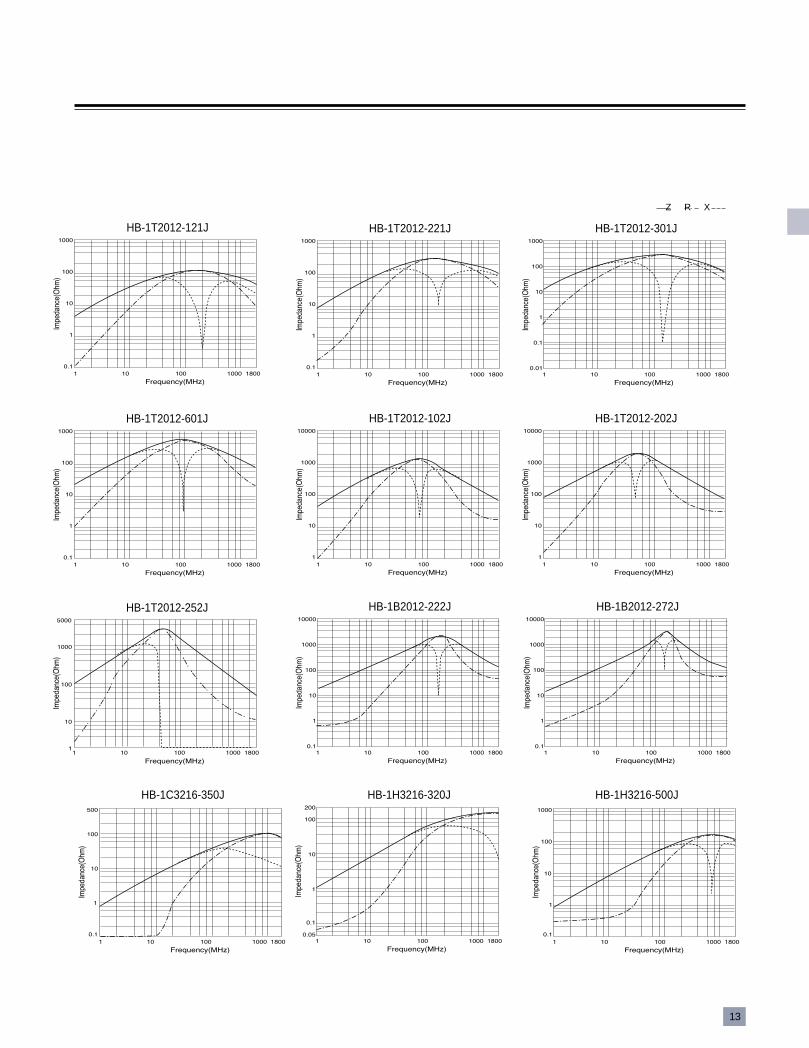
HB-1T2012-121J
Z R X
HB-1T2012-221J HB-1T2012-301J
HB-1T2012-601J HB-1T2012-102J HB-1T2012-202J
HB-1B2012-222J HB-1B2012-272JHB-1T2012-252J
HB-1C3216-350J HB-1H3216-320J HB-1H3216-500J

14
Z R X
HB-1H3216-700J HB-1M3216-121J
HB-1M3216-201J
HB-1M3216-151J
HB-1M3216-301J HB-1M3216-501J
HB-1M3216-601J HB-1M3216-102J HB-1S3216-200J
HB-1S3216-800J HB-1S3216-251J HB-1S3216-601J

15
Z R X
HB-1T3216-350J HB-1T3216-500J HB-1T3216-121J
HB-1T3216-151J HB-1T3216-201J HB-1T3216-601J
HB-1T3216-102J HB-1T3216-122J
HB-1H4516-700J HB-1M4516-151J HB-1T4516-700J

16
Z R X
HB-1H4532-151JHB-1T4532-121JHB-1H4532-121J
HB1608,HB2012·HB series(For ultra high speed signal line)
HB-1L1608-2R0 HB-1L1608-4R0 HB-1L1608-5R5
HB-1L1608-7R0 HB-1L1608-9R0 HB-1L1608-130
HB-1L1608-150 HB-1Y1608-4R0 HB-1Y1608-100

17
Z R X
HB-1L2012-3R5 HB-1L2012-6R5 HB-1L2012-100
·HH,HU series
HH-1M1608-600J
HH-1M2012-600JHH-1H2012-260J HH-1M2012-121J
HH-1M1608-300J HH-1M1608-121J
HH-1M2012-221J HH-1T2012-260JHH-1M2012-301J

18
HH-1M3216-501J
Z R X
HH-1M4516-600J
HH-1M2012-601J HH-1T2012-251J HH-1S2012-8R0
HH-1H3216-500J HH-1M3216-121J
HH-1M3216-601J HH-1H4516-600J
HH-1H4532-121J HH-1T4532-121J HH-1M4532-132J

19
HU-1M2012-800J
HU-1M2012-400J
Z R X
HH-1B4532-132J HH-1M5750-401J
HU-1H3216-500J HU-1H4516-600J
HU-1M2012-600J HU-1M2012-121J
HU-1H4532-121J
HU-1M5750-401J

RELIABILITY AND TEST CONDITIONS
58
CHIP FERRITE BEADS
ITEM
Operating temp.range
Storage temp. & humidityrange
Resistance to solder heat
Solderability
Reflow soldering
Tensile strength(Terminal strength)
Adhension ofterminal electrode(Flexure strength)
Body strength(Bending strength)
TEST CONDITIONREQUIREMENTS
1005 1608 2012 3216 4516 4532 5750
-55¡ ~+125¡
40¡ max. , 70% RH max.
1. No damage such as cracks should be caused in chip element.2. More than 75% of the terminal electrode shall be covered with new solder.3. Impedance change : ¡ within 30%
Preheat temperature : 100 to 150¡Preheat time : 1min.Solder temperature : 260 ¡ 10¡Dipping time : 10 ¡ 0.5sec.
at packing condition
Preheat temperature : 100 to 150¡Preheat time : 1min.Solder temperature : 230 ¡ 10¡Dipping time : 3 ¡ 1sec.
Preheat temperature : 150¡Preheat time : 1min.Solder temperature : 230¡Soldering time: 10 sec. max.(Reflow soldering profile)
1. More than 90% of the terminal electrode shall be covered with new solder.2. Impedance change : ¡ within 30%
1. More than 50% of the terminal electrode shall be covered with new solder.
1. No mechanical damage
1. No mechanical damage
1. The body shall not be damaged by forces applied on the right.
unit:Kgf (W)
- 1.0 2.0 2.5 2.5 3.0 3.0
unit: mm (a,b,c) , Kgf (W)
a
b
c
W
W
0.7
0.5
0.7
0.7
1.0
0.8
1.3
2.0
1.0
1.0
1.3
4.0
1.3
1.5
3.0
5.0
1.5
3.6
3.0
5.0
1.5
3.6
3.8
5.0
1.8
4.6
5.8
5.0
unit: mm (d) , Kgf (W)
d
W
-
-
1.3
2.0
1.3
3.0
2.0
4.0
3.0
4.0
3.8
5.0
4.8
5.0
¢”
¢”
¢”
¡
¡ª
¡ª
¡
¢”¢”
¢”
¢”
¢”
¢”
¢”
¢”
¢”
RO.5
W
W
SS¡ˆ T*0.5
T
W(Kgf) min.
c
a Land Pattern
b
a
¢”
¢”
RO.5
W
1.0mm
¢”
¢”
T
¢”
¢”
¢” d

59
CHIP FERRITE BEADS
ITEM
Drop
Vibration
TEST CONDITIONREQUIREMENTS
1005 1608 2012 3216 4516 4532 5750
1. No mechanical damage2. Impedance change : ¡ within 30%
Drop 10 times on a concrete floor froma height of 91cm.
Frequency : 10~55~10HzAmplitude : 1.52 mmDirection and time : X,Y,Z directions for2 hours
1. No mechanical damage2. Impedance change : ¡ within 30%
Thermal shock(Temperature cycle)
Step1. -40 ¡ 3¡ 30 ¡ 3min.Step2. 85 ¡ 3¡ 30 ¡ 3min.Number of cycle : 100 times
1. No mechanical damage2. Impedance change : ¡ within 30%
Heat load resistance Temperature : 85 ¡ 2¡Applied current : rated currentTime : 1,000 hoursMeasured at room ambient temperatureafter placing for 24 hours
1. No mechanical damage2. Impedance change : ¡ within 30%
Low temp. resistance Temperature : -40 ¡ 5¡Time : 1,000 hoursMeasured at room ambient temperatureafter placing for 24 hours
1. No mechanical damage2. Impedance change : ¡ within 30%
Humidity resistance Temperature : 40 ¡ 2¡Humidity : 90~95% RHTime : 500 hoursMeasured at room ambient temperatureafter placing for 24 hours
1. No mechanical damage2. Impedance change : ¡ within 30%
Humidity load resistance Temperature : 40 ¡ 2¡Humidity : 90~95% RHApplied current : rated currentTime : 500 hoursMeasured at room ambient temperatureafter placing for 24 hours
1. No mechanical damage2. Impedance change : ¡ within 30%

81
PACKING
Type Q¡flTY(PCS) REMARKS
15,000
10,000
50,000
10,000
4,000
8,000
3,000
7,000
3,000
7,000
3,000
1,500
1,000
BULK CASSETTE
4mm pitch
∮254mm
∮254mm
1005
0603
1608
2012
3216
4516
4532
5750
PRODUCT Type A¡ 0.1 B¡ 0.1 P¡ 0.1 Ko¡ 0.1 T(max.)
1608
2012
2012
3216
3216
1.00
1.45
1.90
1.90
1.90
1.80
2.25
2.25
3.60
3.60
4.0
4.0
4.0
4.0
4.0
0.95
1.35
1.00
1.35
0.3
0.3
0.3
0.3
0.3
CHIP BEADSCHIP BEADS ARRAYCHIP FERRITE INDUCTORCHIP EMI SUPPRESSIONFILTERCHIP EMI FILTER ARRAYCHIP LC FILTERCHIP COMMON MODE FILTERCHIP FEEDTHRU CHIP VARISTORCHIP VARISTOR ARRAYCHIP SURGE ABSORBER
Type W[mm]
0603, 1005, 1608, 2012, 3216 Array
4516, 4532, 5750
9.0±0.3
13.0±.0.3]
■ STANDARD QUANTITY ■ REEL DIMENSION
■ TAPING DIMENSION / 8mm wide
0.081.00
unit:mm
unit:mm
§j178¡ 2.0§j254¡ 2.0
less than 1.5
more than 50
W
§j21.0¡ 0.8
§j13.0¡ 0.5
R1.0
2.0¡ 0.8
A
B
P
T
Ko2.0¡ 0.05
Sprocket hole
¡⁄ Embossing Tape
unit:mm
Chip cavity§j1.5 +0.1-0
4.0¡ 0.1
8.0¡
0.3
1.75¡ 0.1
‹H
3.5¡
0.05

82
PRODUCT Type A¡ 0.1 B¡ 0.1 P¡ 0.1 T(max.)
0603
1005
1608
0.37±0.02
0.65±0.1
1.00±0.1
0.67±0.02
1.15±0.1
1.8±0.1
4.0±0.1
2.0±0.1
2.0±0.1
0.45
0.8
1.1
MICRO INDUCTORCHIP BEADSCHIP INDUCTORCHIP VARISTORCHIP SURGE ARRAY
■ TAPING DIMENSION / 12mm wide
PRODUCT Type A¡ 0.1 B¡ 0.1 P¡ 0.1 Ko¡ 0.1 T(max.)4516451645325750
1.901.903.605.20
4.904.904.906.10
4.04.08.08.0
1.001.351.402.05
0.30.30.30.3
CHIP BEADSCHIP FEEDTHRU
unit ; mm
A
B
‹ H
‹H ‹H
‹H
P‹ H
‹H T‹ H
‹H
2.0¡ 0.05
Sprocket hole
¡⁄ Paper Tape
unit:mm
Chip cavity§j1.5 +0.1-0
‹ H‹H
4.0¡ 0.1‹ H
‹H
‹H
‹H
8.0¡
0.3
1.75¡ 0.1
‹H
‹H
‹H
‹H
‹H
‹H
‹H
3.5¡
0.05
A
B
‹ H
‹H ‹H
‹H
P‹ H
‹H T‹ H
‹H
Ko
‹ H
‹H
2.0¡ 0.05
Sprocket hole
unit:mm
Chip cavity§j1.5 +0.1-0
‹ H‹H
4.0¡ 0.1‹ H
‹H
‹H
‹H
12.0
¡0.
3
1.75¡ 0.1
‹H
‹H
‹H
‹H
‹H
‹H
‹H
5.5¡
0.05
¡⁄ Embossing Tape

83
§ TOP TAPE STRENGTH
§ TAPING MATERIAL
§ LEADER AND BLANK PORTION
¡⁄ The force for tearing off top tape is 20 to 70 grams in the arrow direction.
¡⁄ Embossed Tape ¡⁄ Paper Tape
‹ H
‹ H ‹ H
‹H
‹H ‹H
‹H
‹H
‹H
‹ H‹ H
‹H
‹H ‹H
Unit:mm
+0-0.2
12¡ 0.1
110¡ 0.7
Slider Shutter
Connecting Port
Top tape
Embossing tape
Embossment
Embossed carrier
Plastic/thermallyactivated adhesive
165¡ £to 180¡ £
36
+0.2
-031
.5
+0-0.11.0
+0.2-0.1
2.0+0.1-01.5
+0 -0.2
36
‹ H
‹H
‹H
‹H
‹H
‹H
‹H‹H
‹H
‹H
‹H‹H
‹H
6.8¡
0.1
8.8¡
0.1
12.1
¡0.
1
Top tapeTop tape
Paper tape
Bottom tape
Chip cavity
Sprocket hole
‹ H
‹H
‹H
‹H
‹ H
‹ H
‹H ‹H
20 to 40 pitches 210mm to 250mm
Drawing direction
Blank Portions Blank Portions LeaderChip Cavity‹ H
‹H ‹H
‹ H‹ H
¡⁄ The pitch holes shift within ¡ 0.3mm for cumulative 10 pitches.
§ 1005 BULK CASSETTE DIMENSION
‹H
10 to 20 pitches
‹H

84
e
fLand pattern
Land pattern Land pattern
fLand pattern
<2012 size> <3216, 4516 size>
<3 array> <4 array>
LAND PATTERN DESIGN
■ BEAD, INDUCTOR, VARISTOR, SURGE ABSORBER
■ ARRAY
■ EMI SUPPRESSION FILTER, LC FILTER, FEEDTHRU CAPACITOR
SIZE a b c06031005160820123216451645325750
0.220.71.01.01.11.51.82.0
0.250.40.61.02.23.03.04.0
0.320.50.81.01.41.43.05.8
unit ; mm
SIZE array a b c d32163216
3 array4 array
1.00.8
0.80.8
3.03.0
0.50.4
unit ; mm
SIZE a b c d e f201232164516
1.01.11.5
1.01.41.4
0.40.60.8
2.02.42.4
0.1--
1.42.43.4
unit ; mm

85
LAND PATTERN DESIGN
■ COMMON MODE FILTER, VARISTOR ARRAY
SIZE POLE(Array) a b c d2012201232163216
2 POLE2 Array2 POLE2 Array
1.200.762.101.96
0.600.380.800.76
2.602.163.002.54
0.400.460.600.90
unit ; mm
SIZE POLE(Array) a b c d e3216 4 Array 0.8 0.8 3.0 0.4 2.4
unit ; mm
Land pattern
e
¡ÆEMI FILTER ARRAY

86
SOLDERING PROFILE
■ REFLOW SOLERING PROFILE
■ FLOW SOLDERING PROFILE
■ MANUAL SOLDERING
preheating 100 sec. max.
soldering 10 sec. max.
cooling 60 sec. min.
60 sec. min.
20 sec. max.
solder iron max. 30W
Diameter of solder iron 1.2 mm max.
soldering 2 sec. max.
¥˜T¡´ 200¡ /0.5 sec.
300¡
250¡
230¡
200¡
150¡
150¡
Tc¡
preheating 100 sec. max.
dipping 10 sec. max.
cooling 60 sec. min.
60 sec. min.
Top Related