


Languages
Pages
Legal


Journal of Engineering Science and Technology Vol. 13, No. 12 (2018) 4240 - 4257 © School of Engineering, Taylor’s University
4240
CHARACTERIZATION OF ABRASIVE WEAR PROPERTIES OF PLASMA SPRAYED ALUMINA AND YSZ COATINGS
ON ALUMINIUM 6061 SUBSTRATE
HARIDASANAYAK1,*, N. KRISHNAMURTHY2, M. S. MURALI3
1Department of Mechanical Engineering, PESIT,
Bangalore South Campus, Bengaluru-560100 India 2Department of Mechanical Engineering, Vijaya Vittala Institute of Technology,
Dodda Gubbi, Bengaluru-560077, India 3ACS College of Engineering, Kambipura, Bengaluru-560074, India
*Corresponding Author: [email protected], +91 9448797243
Abstract
On the embarked journey of curtailing heat losses and dwindling wear in internal
combustion engines and gas turbines, Thermal Barrier Coatings (TBCs) play a
prominent role. As TBC increase the efficiency of the engine by reducing heat
losses. Review of the literature reveals one of the favoured techniques for the
application of TBC is by atmospheric plasma spraying and delving of wear
characteristics of TBC by plasma spraying are to be effectuated. To fill this
research void, the investigation is carried out with a three-layered TBC on
aluminium 6061 base/substrate material. The substrate was first coated with a
metallic bond material (Al 25Fe7Cr5Ni) and above that, a cermet bond material
(Al2O3 30(Ni20Al)) was applied. The third top layer was a pure ceramic coat,
which encompasses the mixture of pure alumina (Al2O3) and Yttria-Stabilized
Zirconia (YSZ; ZrO28Y2O3) in equal proportions. The topcoat thickness of pure
ceramic was varied (100, 200 and 300 µm) and the coated samples were subjected
to various studies (microstructure, XRD analysis, porosity and abrasive wear).
Conscientious inquests of results divulge reliance of coefficient of friction and
wear on loading conditions, initially wear is by the result of abrasion and once
the bond coat was revealed it is by adherence and wear rate decreases with
increase in load. Feasibility of Al2O3 and ZrO28Y2O3 as a thermal barrier coating
was espied and enhanced wear characteristics emanated.
Keywords: Abrasive wear, Microstructure, porosity, Plasma spraying, Thermal
barrier coatings, Yttria Stabilized Zirconia (YSZ).

Characterization of Abrasive Wear Properties of Plasma Sprayed . . . . 4241
Journal of Engineering Science and Technology December 2018, Vol. 13(12)
1. Introduction
The stability of hot section parts in IC engine is ascertained by Thermal Barrier
Coatings (TBCs) [1]. TBCs in IC engines will develop superior power density, fuel
effectiveness and multi-fuel capability owing to higher combustion chamber
temperature [2]. In the development of thermal barrier coating, the most expedient
and imperative spraying techniques are atmospheric plasma spraying, because of
its high temperature.
Manufacturing industry and public utilities encompass and function a
voluminous number of plants and machinery whose components in motion endure
severe wear and losses incurred due to wear is enormous. It is reported that an
estimated wear loss incurred amounts to nearly about 0.25 per cent of their turnover
[3]. The repercussion of wear instigates reduced efficiency, increased power losses,
increased fuel consumption and rate of a component substitute. In many
circumstances, these problems can be addressed by making appropriate design
and/or material changes, to dwindle or eliminate wear. The cylinder bore of
aluminium alloy engine block undergoes surface treatment to make it wear
resistant, thereby eliminating the need for cast-iron sleeves. Several European and
Japanese automobile manufacturers have delved to explore cylinder bore plasma
spray technology [4]. Plasma sprayed cylinder bores in engines, which are
frequently operated in harsh environments under severe conditions, therefore,
demand reliably wear-resistant sliding surfaces.
Yttria partially stabilized with zirconia used as a thermal barrier by atmospheric
plasma spraying coating on a wide range of superalloy substrate, cast iron substrate,
an aluminium substrate helps to protect the substrate from corrosion. These barrier
coatings exhibit qualities of high thermal expansion coefficient that will reduce the
degradation of coating in long service life and also possess very low thermal
conductivity to the surrounding. These coatings exhibit very good characteristics,
such as resistance to abrasive wear. Plasma sprayed with equal proportions of YSZ
(ZrO28Y2O3) and Alumina composite coatings are used to improve the resistance
against various forms of wear and breakdowns.
Leivo et al. [5] commented that uncontaminated alumina (Al2O3) is pre-
dominantly used as a wear protection coating in mechanical applications. It is
notable that the microhardness value of the coating is a prominent parameter for
the wear resistance of the coating, quality, microstructure, and defect content [6-
10]. Hardness greatly affects the wear of materials, as crack strength is a major
aspect considered in brittle fracture [11]. Wear behaviour of Atmospheric Plasma
Sprayed (APS) and Vacuum Plasma Sprayed (VPS) coatings have been observed
to be dependent on the levels of residual stress present in the coatings [12]. The
value of hardness is also the measure of the resistance of materials to abrasive
wear and the levels of residual stress in thin films have additionally been related
with hardness, obviously demonstrating that the resistance of the coating to
deformation process must play an important role in the wear tests [13]. The wear
resistance of plasma sprayed alumina increases with an increase in compressive
residual stress in the coatings [14]. To get the best wear properties, it is
thus, critical to exploit these stresses without compromising on the coating
substrate adherence.
The engine cylinder liner material used in the lightweight motor vehicle is
predominantly Aluminium and in heavy vehicles, it is made by cast iron. Engine
4242 Haridasanayak et al.
Journal of Engineering Science and Technology December 2018, Vol. 13(12)
liners severely undergo abrasive wear when it abrades with piston rings and also
allows more heat loss through it. It is required to replace conventional engine
cylinder liner by an abrasive wear-resistant and heat-resistant coating. The main
objective of this work is to develop a wear and corrosion resistant thermal barrier
coating materials for the Internal combustion Engine. In this perspective, the
current investigation has been carried out.
The remainder of the paper is organized as follows: Section 2 of the paper
iterates the experimental plan adopted for the investigation. The outcomes of the
experimental investigation are discussed in Section 3 and Section 4 concludes with
important findings of the research.
2. Experimental Details
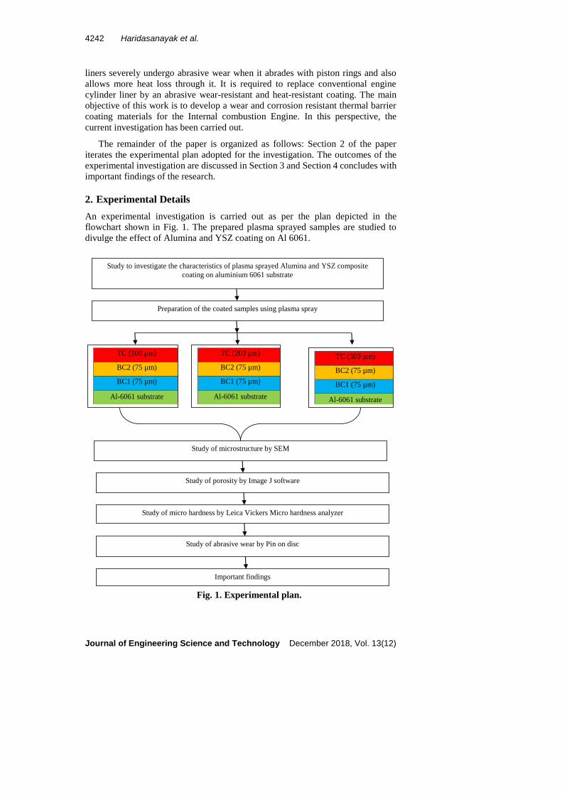
An experimental investigation is carried out as per the plan depicted in the
flowchart shown in Fig. 1. The prepared plasma sprayed samples are studied to
divulge the effect of Alumina and YSZ coating on Al 6061.
Fig. 1. Experimental plan.
Study of abrasive wear by Pin on disc
Study of porosity by Image J software
Study of micro hardness by Leica Vickers Micro hardness analyzer
Important findings
Study of microstructure by SEM
TC (100 µm)
BC2 (75 µm)
BC1 (75 µm)
Al-6061 substrate
TC (300 µm)
BC2 (75 µm)
BC1 (75 µm)
Al-6061 substrate
TC (200 µm)
BC2 (75 µm)
BC1 (75 µm)
Al-6061 substrate
Preparation of the coated samples using plasma spray
Study to investigate the characteristics of plasma sprayed Alumina and YSZ composite
coating on aluminium 6061 substrate

Characterization of Abrasive Wear Properties of Plasma Sprayed . . . . 4243
Journal of Engineering Science and Technology December 2018, Vol. 13(12)
2.1. Preparation of plasma sprayed coating samples
Al-6061cylindrical pins of dimensions 12 mm × 25 mm (diameter × length) were
chosen as a substrate material for coating. Al-6061 substrate constitution material
is tabulated in Table 1. Initially, dimension accuracy is checked for substrate
material as well as surface smoothness. The surfaces to be sprayed were coarsened
with grit blasts and later the surfaces were cleaned and degreased by immersing in
a shower of acetone. The coating was deposited using a Sulzer Metco plasma
spraying apparatus, as per the experimental plan sketched in Fig. 2. Table 1 portrays
the trade names and synthetic constitutes of bond and top coat materials. Table 2
lists the details of the spray criterions for different materials.
Fig. 2. Sketch of coated specimen (Top Coat (TC),
Bond Coat 1 (BC1), Bond Coat 2 (BC2)).
Table 1. Substrate and coating material chemical constituents.
Trade Name and Chemical constituents
Al-6061 substrate Top Coat
(TC)
Bond Coat 1
(BC1)
Bond Coat
(BC2)
Si-0.65, Fe-0.25,
Cu-0.25, Mn-0.03,
Mg-0.89, Zn-0.01,
Cr-0.07, V-0.01,
Ti-0.02, Al-rest
50% Metco105SFP
+50%204NS
50% Al2O3+50%
ZrO2 8Y2O3
Metco 446
Al 25Fe7Cr5Ni
Metco 410 NS
Al2O3
30(Ni20Al)
Table 2. Parameters for plasma spray.Material Primary gas
pressure
(argon)
kPa
Secondary
gas pressure
(hydrogen)
kPa
Carrier gas
(argon) flow
lpm
Current
A
Voltage
V
Spray
distance
mm
Feed
rate
kg/h
TC 700 520 60 600 65 64-125 2.7
BC1 520 340 37 500 70 100-500 3.2
BC2 700 350 37 500 65 75-125 1.6
2.2. Characterisation of coated samples
The morphology of coated samples was examined using Carl Zeiss, Neon 40
Crossbeam and Field Emission Scanning Electron Microscope (SEM). For
determining coating thickness and porosity, samples were prepared as appended in
the forthcoming discussion. The mounted specimens were glazed utilizing emery
TC (100 µm)
BC2 (75 µm)
BC1 (75 µm)
Al-6061 substrate
TC (200 µm)
BC2 (75 µm)
BC1 (75 µm)
Al-6061 substrate
TC (300 µm)
BC2 (75 µm)
BC1 (75 µm)
Al-6061 substrate
Sample 1 (S1) Sample 2 (S2) Sample (S3)
4244 Haridasanayak et al.
Journal of Engineering Science and Technology December 2018, Vol. 13(12)
papers of 240, 300, 400, 600 grades and fine polished by 1/0, 2/0, 3/0 and 4/0 grades.
ASTM International [15] is referred before the preparing the metallographic surface.
First preparation step should aim to remove any cracks that arise from cutting without
introducing new damage from coarse emery paper. During preparation of
metallographic surface, a lot of care taken to avoid edge dislocation. Finally, coated
specimens were subjected to fine glazing to obtain a mirror finish by a process of
utilizing 0.5 µm paste of diamond impregnated material cloth. The glazed coated
samples were cleaned with acetone before mounting on Scanning Electron
Microscope (SEM) to study the microstructure of coating [16, 17]. The porosity of
the coating is measured using Image J Software.
The specimens are subjected to X-Ray diffraction to know the constituent and
phase of the coated specimen. The X-Ray Diffractometer (Make: Bruker D8
Advance, Germany) with a 0.6˚ difference slit is used, the measurement conditions
were Cu-Kα radiation, acceleration voltage 40 kV, and beam current 40 mA, 2 theta
range = 20˚ to 100o.
2.3. Measurement of Microhardness
According to ASTM International [18], Leica Vickers Microhardness analyzer is
used to find the hardness of the coating (Show: MMTX7, make: MATSUZAWA,
Auto) as per ASTM E384-16 standard. The test parameters are; 100 g load, 15 mg/s
loading rate, 10 seconds stay time with a Vickers Pyramid indenter. The estimation
of hardness was done along the thickness of the coating layers. An average of ten
estimates was taken at various areas on the transverse segment of the coating.
2.4. Abrasive wear test
According to ASTM G99 standard [19], the abrasive wear test was carried out as
per on coated specimens. Table 3 shows the test parameters considered in
carrying out abrasive wear test. Prior to testing, specimens were cleaned and
dried. Care was taken to eliminate all dirt and foreign matter from the specimen
by cleaning the specimen with non-chlorinated non-film forming agent and
dissolver. Specimens were dried with open grain to remove all traces of the
cleaning fluid that may be entrapped in the material. The dimensions of the
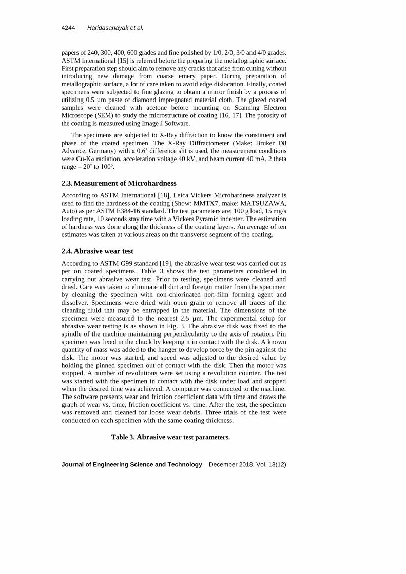
specimen were measured to the nearest 2.5 µm. The experimental setup for
abrasive wear testing is as shown in Fig. 3. The abrasive disk was fixed to the
spindle of the machine maintaining perpendicularity to the axis of rotation. Pin
specimen was fixed in the chuck by keeping it in contact with the disk. A known
quantity of mass was added to the hanger to develop force by the pin against the
disk. The motor was started, and speed was adjusted to the desired value by
holding the pinned specimen out of contact with the disk. Then the motor was
stopped. A number of revolutions were set using a revolution counter. The test
was started with the specimen in contact with the disk under load and stopped
when the desired time was achieved. A computer was connected to the machine.
The software presents wear and friction coefficient data with time and draws the
graph of wear vs. time, friction coefficient vs. time. After the test, the specimen
was removed and cleaned for loose wear debris. Three trials of the test were
conducted on each specimen with the same coating thickness.
Table 3. Abrasive wear test parameters.
Characterization of Abrasive Wear Properties of Plasma Sprayed . . . . 4245
Journal of Engineering Science and Technology December 2018, Vol. 13(12)
Sliding speed (m/min) 50.26, 56.54, 62.83 for track diameter of 80, 90, 100 mm respectively Sliding distance (m) 201 m Load (N) 5, 10, 15 Sample size (mm) 25 mm length × 12 mm diameter, coated on 12 mm face Disk Alumina abrasive wheel
Disk specifications WA60K5V
Test temperature Room temperature, dry condition
Fig. 3. Abrasive wear testing machine.
3. Results and Discussion
3.1. Coating morphology
The morphology of coating texture reveals critical information with regards to the
distribution of the coating on the substrate. Figure 4 illustrates the morphology of
coated samples S1, S2 and S3. Careful insight reveals that the top coat consists of
melted and semi-melted particles, splats and unmelted particles. The coated surface
also possesses voids and microcracks (from the enlarged view). Melted or semi-
melted particles deform during the spraying process and lead to the formation of
small pores. Semi-melted particles are easy to fragment during the deforming
process and form small pores. Unmelted particles could not fully deform during the
spraying process. Smooth areas of the microstructure represent the molten particle
and coarse one represents the semi-molten particles. The presence of microcracks
is mainly because of the spraying procedure arrangement of residual stresses
created by thermal shock [20].
Figure 5 indicates an SEM cross-section of the sprayed specimen, espying
variation in coating thickness. The actual coating deposited varies from ±15 µm to
±30 µm, due to variation in speed of spraying gun. This variation can be overcome
by using Robot Plasma spraying method.

4246 Haridasanayak et al.
Journal of Engineering Science and Technology December 2018, Vol. 13(12)
Fig. 4. Morphology of coated samples for S1, S2, S3 and enlarged view.
Fig. 5. SEM Micrographs showing cross sections of coated samples.
3.2. Porosity
Presence of porosity leads to corrosion, crack formation and also relieves residual
stresses. Figure 6 shows the pores present in the bond and top layers of coating systems.
Table 4 gives the percentage of average porosity of different coating systems.
The porosity obtained is less as compared with that of previous work reported [21-
24]. The porosity of the top coat increases with the thickness of the coat.
S1
MELTED
PARTICLES
UNMELTED
PARTICLES
CRACKS
VOIDS
S2
CRACKS
MELTED PARTICLES
UNMELTED PARTICLES
S3
MELTED PARTICLES
UNMELTED PARTICLES
MICRO CRACKS
VOIDS
ENLARGED VIEW
MOLTEN PARTICLES
CRACK
UNMOLTEN PARTICLES
S1
TC
BC
Al 6061 Substrate
BC
Al 6061 Substrate
S2
TC
BC
TC
S
Al 6061 Substrate

Characterization of Abrasive Wear Properties of Plasma Sprayed . . . . 4247
Journal of Engineering Science and Technology December 2018, Vol. 13(12)
The main reason for the formation of pores in coating systems is residual stresses,
which are formed during the coating process. The impact generated by quenching of
molten particles during spraying causes a distinction in the extent of coefficients of
thermal expansion between the coating and the substrate, which results in the formation
of residual stresses.
As the time of exposure of plasma gun increases (in the case of S2 and S3), the
quantity of residual stresses formed also increases.
Figure 7 shows the variation of porosity with different coating thickness for bond
coat as well as top coat, from the figure it is concluded that the porosity of the coating
is increases with increase in coating thickness, S3 will exhibits (1.757% for topcoat)
more porosity, while S1 exhibits less porosity (1.033%).
Fig. 6. Micrographs showing porosity in coatings systems.
Table 4. The porosity of coating systems.
Samples Porosity of Bond
coat %
Porosity of Top
coat %
S1 1.01 1.033
S2 1.635 1.592
S3 1.506 1.757
Fig. 7. Variation of porosity in bond and top coats.
3.3. XRD Analysis
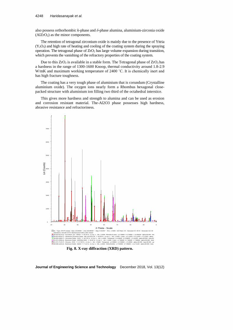
X-Ray Diffraction pattern of coating systems is as shown in Fig. 8. The coating
systems mainly consist of Zirconium oxide (ZrO2) in the tetragonal phase and α-
Al2O3 in crystalline polymorphic phase as the major components. Coating systems
4248 Haridasanayak et al.
Journal of Engineering Science and Technology December 2018, Vol. 13(12)
also possess orthorhombic k-phase and δ-phase alumina, aluminium-zirconia oxide
(AlZrO2) as the minor components.
The retention of tetragonal zirconium oxide is mainly due to the presence of Yttria
(Y2O3) and high rate of heating and cooling of the coating system during the spraying
operation. The tetragonal phase of ZrO2 has large volume expansion during transition,
which prevents the vanishing of the refractory properties of the coating system.
Due to this ZrO2 is available in a stable form. The Tetragonal phase of ZrO2 has
a hardness in the range of 1300-1600 Knoop, thermal conductivity around 1.8-2.9
W/mK and maximum working temperature of 2400 ˚C. It is chemically inert and
has high fracture toughness.
The coating has a very tough phase of aluminium that is corundum (Crystalline
aluminium oxide). The oxygen ions nearly form a Rhombus hexagonal close-
packed structure with aluminium ion filling two third of the octahedral interstice.
This gives more hardness and strength to alumina and can be used as erosion
and corrosion resistant material. The-Al2O3 phase possesses high hardness,
abrasive resistance and refractoriness.
Fig. 8. X-ray diffraction (XRD) pattern.
A1
00-046-1215 (I) - Aluminum Oxide - Al2O3 - Y: 7.21 % - d x by: 1. - WL: 1.5406 - Orthorhombic - a 7.93400 - b 7.95600 - c 11.71100 - alpha 90.000 - beta
01-072-7115 (*) - Zirconia - ZrO2 - Y: 117.83 % - d x by: 1. - WL: 1.5406 - Tetragonal - a 3.59800 - b 3.59800 - c 5.18500 - alpha 90.000 - beta 90.000 - ga
01-074-2206 (I) - Aluminum Oxide - (Al2O3)5.3333 - Y: 26.02 % - d x by: 1. - WL: 1.5406 - Cubic - a 7.90600 - b 7.90600 - c 7.90600 - alpha 90.000 - beta
00-050-1089 (*) - Zirconium Oxide - ZrO2 - Y: 107.04 % - d x by: 1. - WL: 1.5406 - Tetragonal - a 3.59840 - b 3.59840 - c 5.15200 - alpha 90.000 - beta 90.
00-053-0559 (*) - Aluminum Zirconium Oxide - Al0.1Zr0.9O1.95 - Y: 60.96 % - d x by: 1. - WL: 1.5406 - Cubic - a 5.11003 - b 5.11003 - c 5.11003 - alpha
00-010-0173 (I) - Corundum, syn - Al2O3 - Y: 33.75 % - d x by: 1. - WL: 1.5406 - Rhombo.H.axes - a 4.75800 - b 4.75800 - c 12.99100 - alpha 90.000 - bet
Operations: Smooth 0.073 | Background 0.055,1.000 | Import
A1 - Type: 2Th/Th locked - Start: 20.00000 ° - End: 99.99638 ° - Step: 0.01036 ° - WL1: 1.5406 - kA2 Ratio: 0.5 - Generator kV: 40 kV - Generator mA: 40
Lin
(C
ounts
)
0
1000
2000
3000
4000
5000
6000
7000
2-Theta - Scale
20 30 40 50 60 70 80 90 100

Characterization of Abrasive Wear Properties of Plasma Sprayed . . . . 4249
Journal of Engineering Science and Technology December 2018, Vol. 13(12)
3.4. Microhardness
The hardness of a material is an indirect measure of wear resistance of it. The
average hardness of different layers of coatings is tabulated in Table 5. There is
noticeable variation in the microhardness of different layers of coatings [23]. The
variation of the hardness of the substrate, BC1, BC2 and TC for the samples are in
the range of 85-88 HV, 200-241 HV, 730-740 HV and 900-930 HV respectively.
An increase in coating thickness eventually decreases the hardness. The decrease
in hardness is related to an increase in porosity comparing Tables 4 and 5. Figure 9
portrays the effect of porosity on hardness. Portinha et al. [25] reported the
outcomes of the investigation are in consensus with findings. Figure 10 shows the
indentation on different layers of coating systems.
Table 5. The average microhardness of the coating system.
Microhardness HV0.1
Samples Substrate BC1 BC2 TC
S1 88 231 740 913
S2 85 241 732 905
S3 86 200 734 900
Fig. 9. Effect of porosity on top coat hardness of the coating systems.
Fig. 10. Microhardness indentation on different layers of coating systems.
895 900 905 910 915
0.6
0.8
1
1.2
1.4
1.6
1.8
Microhardness, HV0.1
Po
rosi
ty,
%
S2 TC
S2 BC2
S2 BC1
4250 Haridasanayak et al.
Journal of Engineering Science and Technology December 2018, Vol. 13(12)
3.5. Abrasive wear
Wear is the interaction among the mating surfaces and especially the ploughing and
rubbing of material on a surface. Abrasive wear happens when a hard-harsh surface
slides over a soft surface. Figures 11-13 demonstrates the variation of wear with
time for various coating under different loading conditions. Careful insight divulges
a sudden rise in wear at the outset, due to the loosened particles possessed by the
coating system. Once these loosened particles are removed, the hard surface of the
coating is exposed to the abrasive disk and wear increases gradually with time.
Further, from figures, it is implicit that wear is directly proportional to load, and
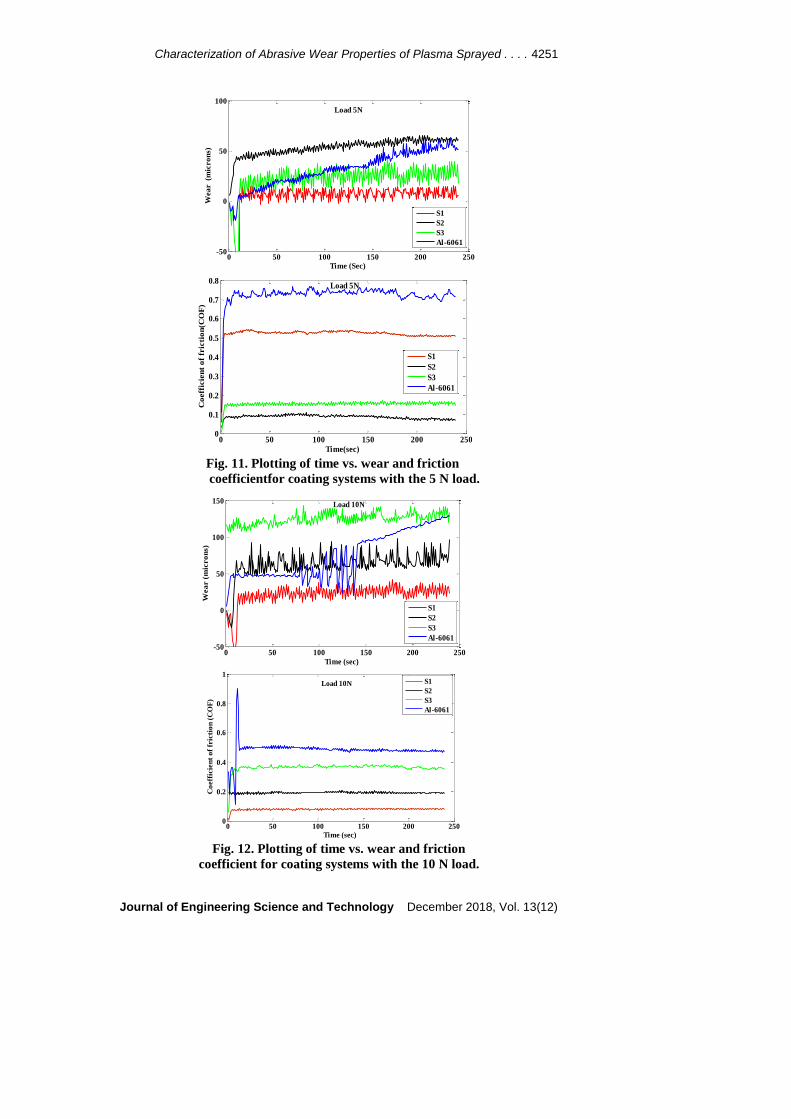
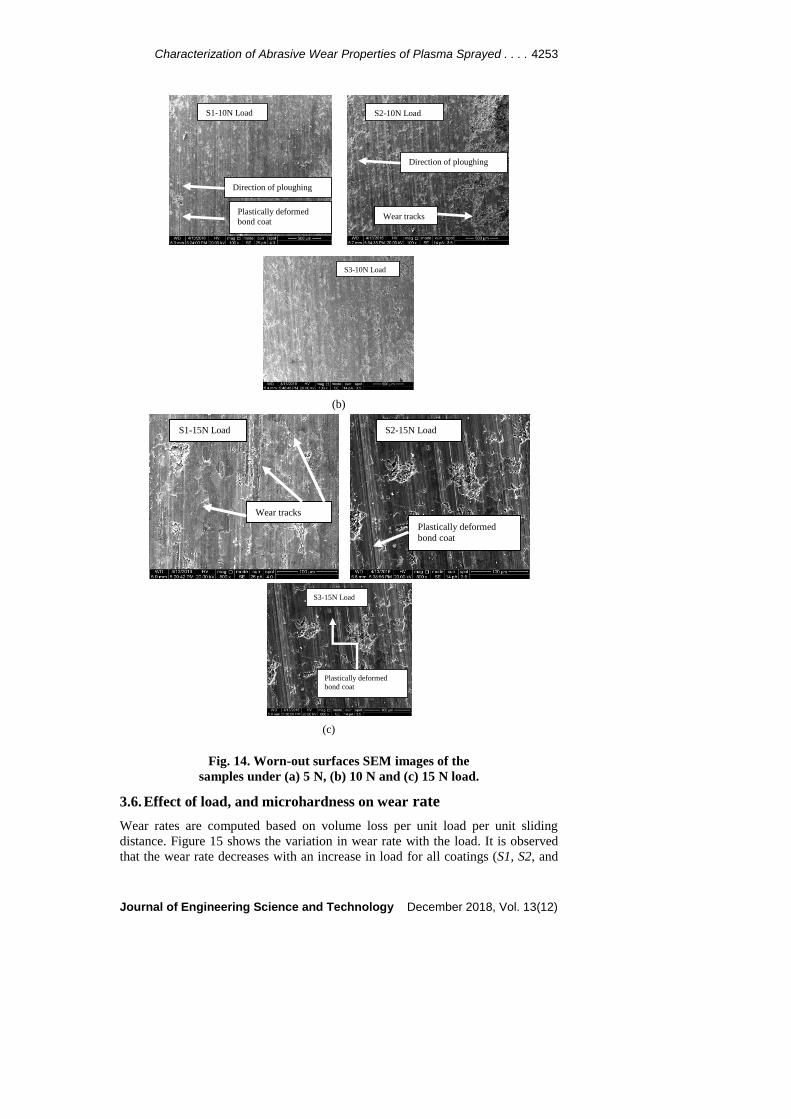
top coat thickness deposited. Microscopic observation of the worn surfaces of
coatings as presented in Fig. 14 indicates that the wear of top coat is by ploughing
mechanism. This wear mechanism also referred to as exfoliation mechanism of
wear [26-29], generates crack between two splats of lamellae due to friction. This
crack increases along the splat limit, which prompts its last peeling from the worn
surface during repeated loading. The stress generated amidst sliding results in the
formation of a crack. In Atmospheric Plasma Sprayed Al2O3 or ZrO28Y2O3
coatings, the fragile interfaces between the progressive lamellae once broken down
exposes the delamination of the coating. This debasement of lamellae of coating
results in progressive wear.
In bond coat the system of wear is predominantly adhesive wear, developing a
surface tribofilm. These tribofilms contain plastically contorted wear debris,
plastically distorted coating material or synthetically adjusted coating surfaces [30,
31]. In the event that no tribofilm is formed, the coating would not avoid the
continuous removal of material. In the present investigation, there is a possibility
for the formation of tribofilm due to the release of wear debris.
During the wear test, the debris formed due to wear of the coating is
continuously being wiped off with a brush. It prevents the formation of tribofilm
leading to an increase in wear. Micrographs of worn surfaces of the coating under
10 N and 15 N load show plastically deformed bond coat particles substantiating
the fact that wear has mainly taken place because of adhesion. The adhesion wear
behaviour can also be seen when the substrate is exposed to the abrasive disk.
Al 6061 substrate, which is very soft undergoes severe wear by the embedding
of wear debris into the hard particles of the abrasive disk. The wear loss increases
till the embedding process of the particles to the disk is saturated. The wear then
starts decreasing; this is mainly due to the glazed property of an embedded layer of
the disk. Therefore, it is suggested that this embedded layer has to be removed
periodically to obtain a quantifiable relationship between wear loss and time.
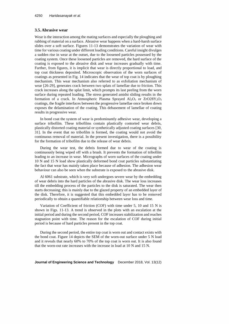
Variation of Coefficient of friction (COF) with time under 5, 10 and 15 N is
shown in Figs. 11-13. A trend is observed in the plots with an escalation at the
initial period and during the second period, COF increases stabilization and reaches
stagnation point with time. The reason for the escalation of COF during initial
period is because of hard particles present in the top coat.
During the second period, the entire top coat is worn out and contact exists with
the bond coat. Figure 14 depicts the SEM of the worn-out surface under 5 N load
and it reveals that nearly 60% to 70% of the top coat is worn out. It is also found
that the worn-out rate increases with the increase in load at 10 N and 15 N.
Characterization of Abrasive Wear Properties of Plasma Sprayed . . . . 4251
Journal of Engineering Science and Technology December 2018, Vol. 13(12)
Fig. 11. Plotting of time vs. wear and friction
coefficientfor coating systems with the 5 N load.
Fig. 12. Plotting of time vs. wear and friction
coefficient for coating systems with the 10 N load.
0 50 100 150 200 250-50
0
50
100
Time (Sec)
Wea
r (m
icro
ns)
Load 5N
S1
S2
S3
Al-6061
0 50 100 150 200 2500
0.1
0.2
0.3
0.4
0.5
0.6
0.7
0.8
Time(sec)
Co
eff
icie
nt
of
fric
tio
n(C
OF
)
Load 5N
S1
S2
S3
Al-6061
0 50 100 150 200 250-50
0
50
100
150
Time (sec)
Wea
r (
mic
ro
ns)
Load 10N
S1
S2
S3
Al-6061
0 50 100 150 200 2500
0.2
0.4
0.6
0.8
1
Load 10N
Time (sec)
Co
eff
icie
nt
of
fric
tio
n (
CO
F)
S1
S2
S3
Al-6061

4252 Haridasanayak et al.
Journal of Engineering Science and Technology December 2018, Vol. 13(12)
Fig. 13. Plotting of time vs. wear and friction
coefficient for coating systems with the 15 N load.
0 50 100 150 200 250-50
0
50
100
150
200
Load 15N
Time (sec)
Wea
r (
mic
ro
ns)
S1
S2
S3
Al-6061
0 50 100 150 200 2500
0.1
0.2
0.3
0.4
0.5
0.6
0.7
0.8
Time (sec)
Co
eff
icie
nt
of
fric
tio
n (
CO
F)
Load 15N
S1
S2
S3
Al-6061
S2-5N Load S1-5N Load
Wear tracks
Wear tracks
(a)
S3-5N Load
Characterization of Abrasive Wear Properties of Plasma Sprayed . . . . 4253
Journal of Engineering Science and Technology December 2018, Vol. 13(12)
Fig. 14. Worn-out surfaces SEM images of the
samples under (a) 5 N, (b) 10 N and (c) 15 N load.
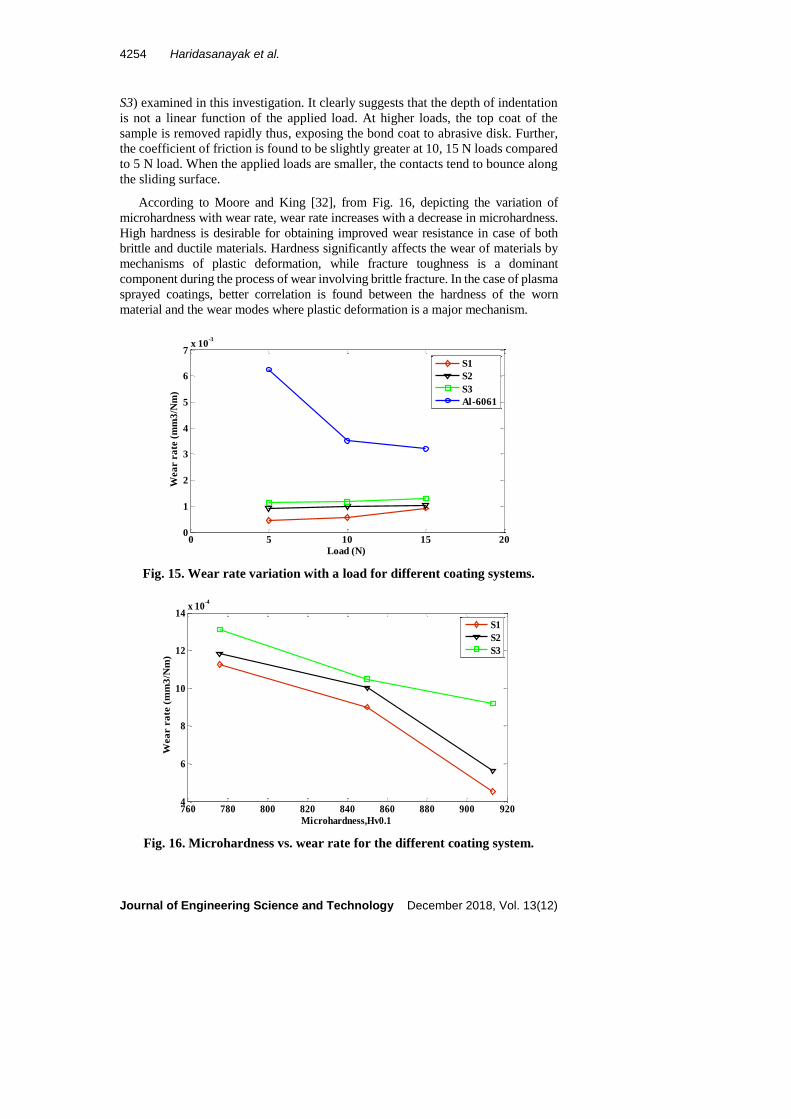
3.6. Effect of load, and microhardness on wear rate
Wear rates are computed based on volume loss per unit load per unit sliding
distance. Figure 15 shows the variation in wear rate with the load. It is observed
that the wear rate decreases with an increase in load for all coatings (S1, S2, and
S1-10N Load S2-10N Load
Direction of ploughing
Direction of ploughing
Plastically deformed
bond coat Wear tracks
(b)
S3-10N Load
S1-15N Load S2-15N Load
Plastically deformed
bond coat
Wear tracks
(c)
S3-15N Load
Plastically deformed
bond coat
4254 Haridasanayak et al.
Journal of Engineering Science and Technology December 2018, Vol. 13(12)
S3) examined in this investigation. It clearly suggests that the depth of indentation
is not a linear function of the applied load. At higher loads, the top coat of the
sample is removed rapidly thus, exposing the bond coat to abrasive disk. Further,
the coefficient of friction is found to be slightly greater at 10, 15 N loads compared
to 5 N load. When the applied loads are smaller, the contacts tend to bounce along
the sliding surface.
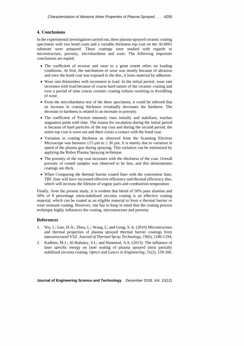
According to Moore and King [32], from Fig. 16, depicting the variation of
microhardness with wear rate, wear rate increases with a decrease in microhardness.
High hardness is desirable for obtaining improved wear resistance in case of both
brittle and ductile materials. Hardness significantly affects the wear of materials by
mechanisms of plastic deformation, while fracture toughness is a dominant
component during the process of wear involving brittle fracture. In the case of plasma
sprayed coatings, better correlation is found between the hardness of the worn
material and the wear modes where plastic deformation is a major mechanism.
Fig. 15. Wear rate variation with a load for different coating systems.
Fig. 16. Microhardness vs. wear rate for the different coating system.
0 5 10 15 200
1
2
3
4
5
6
7x 10
-3
Load (N)
Wea
r r
ate
(m
m3
/Nm
)
S1
S2
S3
Al-6061
760 780 800 820 840 860 880 900 9204
6
8
10
12
14x 10
-4
Microhardness,Hv0.1
Wea
r r
ate
(m
m3
/Nm
)
S1
S2
S3
Characterization of Abrasive Wear Properties of Plasma Sprayed . . . . 4255
Journal of Engineering Science and Technology December 2018, Vol. 13(12)
4. Conclusions
In the experimental investigation carried out, three plasma-sprayed ceramic coating
specimens with two bond coats and a variable thickness top coat on the Al-6061
substrate were prepared. These coatings were studied with regards to
microstructure, porosity, microhardness and wear. The following important
conclusions are espied.
The coefficient of erosion and wear to a great extent relies on loading
conditions. At first, the mechanism of wear was mostly because of abrasion
and once the bond coat was exposed to the disc, it loses material by adhesion.
Wear rate diminishes with increment in load. In the initial period, wear rate
increases with load because of coarse hard nature of the ceramic coating and
over a period of time coarse ceramic coating softens resulting in dwindling
of wear.
From the microhardness test of the three specimens, it could be inferred that
an increase in coating thickness eventually decreases the hardness. The
decrease in hardness is related to an increase in porosity.
The coefficient of Friction intensely rises initially and stabilizes, reaches
stagnation point with time. The reason for escalation during the initial period
is because of hard particles of the top coat and during the second period, the
entire top coat is worn out and there exists a contact with the bond coat.
Variation in coating thickness as observed from the Scanning Electron
Microscope was between ±15 µm to ± 30 µm. It is mainly due to variation in
speed of the plasma gun during spraying. This variation can be minimized by
applying the Robot Plasma Spraying technique.
The porosity of the top coat increases with the thickness of the coat. Overall
porosity of coated samples was observed to be less, and this demonstrates
coatings are thick.
When Comparing the thermal barrier coated liner with the convention liner,
TBC liner will have increased effective efficiency and thermal efficiency also,
which will increase the lifetime of engine parts and combustion temperature
Finally, from the present study, it is evident that blend of 50% pure alumina and
50% of 8 percentage yttria-stabilized zirconia coating is an effective coating
material, which can be coated as an eligible material to form a thermal barrier or
wear resistant coating. However, one has to keep in mind that the coating process
technique highly influences the coating, microstructure and porosity
References
1. Wu, J.; Guo, H.-b.; Zhou, L.; Wang, L; and Gong, S.-k. (2010) Microstructure
and thermal properties of plasma sprayed thermal barrier coatings from
nanostructured YSZ. Journal of Thermal Spray Technology, 19(6), 1186-1194.
2. Kadhim, M.J.; Al-Rubaiey, S.I.; and Hammod, A.S. (2013). The influence of
laser specific energy on laser sealing of plasma sprayed yttria partially
stabilized zirconia coating. Optics and Lasers in Engineering, 51(2), 159-166.
4256 Haridasanayak et al.
Journal of Engineering Science and Technology December 2018, Vol. 13(12)
3. Prasada Rao, A.K.; Das, K.; Murty, B.S.; and Chakraborty, M. (2006).
Microstructural and wear behavior of hypoeutectic Al-Si alloy (LM25) grain
refined and modified with Al-Ti-C-Sr master alloy. Wear, 261(2), 133-139.
4. Bobzin, K.; Ernst, F.; Richardt, K.; Schlaefer, T.; Verpoort, C.; and Flores, G.
(2008). Thermal spraying of cylinder bores with the plasma transferred wire
arc process. Surface and Coatings Technology, 202(18), 4438-4443.
5. Leivo, E.M.; Vippola, M.S.; Sorsa, P.P.A.; Vuoristo, P.M.J.; and Mantyla,
T.A. (1997). Wear and corrosion properties of plasma sprayed Al2O3 and Cr2O3
coatings sealed by aluminium phosphates. Journal of Thermal Spray
Technology, 6(2), 205-210.
6. Tabor, D. (1977). Wear - A critical synoptic view. Journal of Lubricant
Technology, 99(4), 387-395.
7. Cho, S.J.; Moon, H.; Hockey, B.J.; and Hsu, S.M. (1992). The transition from
mild to severe wear in alumina during sliding. Acta Metallurgica et Materialia,
40(1), 185-192.
8. Ramalingam, S.; and Wright, P.K. (1981). Abrasive wear in machining:
experiments with materials of controlled and microstructure. Journal of
Engineering Materials and Technology, 103(2), 151-156.
9. Boas, M.; and Bamberger, M. (1988). The low and abrasive behaviour of
plasma spray and laser melted plasma coatings. Wear, 126(2), 197-210.
10. Khrushchev, M.M. (1974). Principles of abrasive wear. Wear, 28(1), 69-88.
11. Hutchings, I.M. (1992). Tribology: Friction and wear of engineering materials
(1st ed.). Oxford, United Kingdom: Butterworth-Heinemann.
12. Kingswell, R.; Rickerby, D.S.; Scott, K. T.; and Bull, S.J. (1991). Comparison
of the erosive wear behaviour of vacuum plasma sprayed and bulk Alumina.
Proceedings of the Third National Thermal Spray Conference. Long Beach,
California, 179-185.
13. Burnett, P.J.; and Rickerby, D.S. (1988). The scratch adhesion test: An elastic-
plastic indentation analysis. Thin Solid Films, 157(2), 233-254.
14. Bull, S.J.; Kingswell, R.; and Scott, K.T. (1996). The sliding wear of plasma
sprayed alumina. Surface and Coatings Technology, 82(3), 218-225.
15. ASTM International (2014). Standard guide for metallographic preparation of
thermal sprayed coatings. ASTM E1920-03.
16. Morsi, M.S.; El Gwad, S.A.A.; Shoeib, M.A.; and Ahmed, K.F. (2012). Effect
of air plasma sprays parameters on coating performance in zirconia-based
thermal barrier coatings. International Journal of Electrochemical Science,
7(4), 2811-2831.
17. Pal, S.; Deore, A.; Choudhary, A.; Madhwani, V.; and Vijapuri, D. (2017).
Analysis and experimental investigation of ceramic powder coating on
aluminium piston. Fluid Dynamic and Mechanical Sciences, 263, 14 pages.
18. ASTM International (2017). Standard test method for microindentation
hardness of materials. ASTM E384-16.
19. ASTM International (2017). Standard test method for wear testing with a pin-
on-disk apparatus. ASTM G99-17.

Characterization of Abrasive Wear Properties of Plasma Sprayed . . . . 4257
Journal of Engineering Science and Technology December 2018, Vol. 13(12)
20. Krishnamurthy, N; Murali, M.S.; and Mukunda, P.G. (2012). Characterization
and solid particle erosion behaviour of plasma sprayed alumina and calcia-
stabilized zirconia coatings on an Al-6061 substrate. Wear, 274-275, 15-27.
21. Krishnamurthy, N.; Murali, M.S.; Mukunda, P.G.; and Ramesh, M.R. (2010).
Characterization and wear behaviour of plasma-sprayed Al2O3 and ZrO25CaO
coatings on cast iron substrate. Journal of Materials Science, 45(3), 850-858.
22. Dejang, N.; Limpichaipanit, A.; Watcharapasorn, A.; Wirojanupatump, S.;
Niranatlumpong, P.; and Jiansirisomboon, S. (2011). Fabrication and
properties of plasma-sprayed Al2O3/ZrO2 composite coatings. Journal of
Thermal Spray Technology, 20(6), 1259-1268.
23. Campo, L.d.; Meneses, D.D.S.; Wittmann-Teneze, K.; Bacciochini, A.;
Denoirjean, A.; and Echegut, P. (2014). Effect of porosity on the infrared
radiative properties of plasma-sprayed yttria-stabilized zirconia ceramic thermal
barrier coatings. The Journal of Physical Chemistry, 118(25), 13590-13597.
24. Thirumalaikumarasamy, D.; Shanmugam, K.; and Balasubramanian, V.
(2013). Influences of atmospheric plasma spraying parameters on the porosity
level of alumina coating on AZ31B magnesium alloy using response surface
methodology. Progress in Natural Science: Materials International, 22(5),
468-479.
25. Portinha, A.; Teixeira, V.; Carneiro, J.; Martins, J.; Costa, M.F.; Vassen, R.;
Stoever, D. (2005). Characterization of thermal barrier coatings with a gradient
in porosity. Surface and Coatings Technology, 195(2-3), 245-251.
26. Psyllaki, P.P.; Jeandin, M.; and Pantelis D.I. (2000). Microstructure and
wear mechanisms of thermal-sprayed alumina coatings. Materials Letter,
47(1-2), 77-82.
27. Brinkiene, K.; Kezelis, R; Cesniene, J.; and Mecius, J. (2009). Evaluation of
wear resistance of plasma sprayed ceramic coatings. Materials Science, 15(4),
302-305.
28. Rajarathnam, D.R.P.; Jayaraman, M.; Ramasamy, K.K.; Premkumar, M.; and
Narayana, D.S. (2015). An experimental investigation on abrasive wear
behaviour of different ceramics coating on AISI 1040 steel by plasma process.
Middle-East Journal of Scientific Research, 23(6), 1237-1242.
29. Erzi, E.; Dispinar, D.; and Yilmaz, S. (2017). Friction and wear properties of
plasma sprayed YSZ/Ni-Cr-Al coated 6063-T6 aluminum alloy. Achieves of
Foundry Engineering, 17(3), 168-174.
30. Bolelli; G.; Cannillo, V.; Lusvarghi, L.; and Manfredini, T. (2006). Wear
behaviour of thermally sprayed ceramic oxide coatings. Wear, 261(11-12),
1298-1315.
31. Kusoglu; I.M.; Celik, E.; Cetinel, H.; Ozdemir, I.; Demirkurt, O.; and Onel, K.
(2005).Wear behaviour of flame sprayed Al2O3-TiO2 coatings on plain carbon
steel substrates. Surface and Coatings Technology, 200(1-4), 1173-1177.
32. Moore, M.A.; and King, F.S. (1980). Abrasive wear of brittle solids. Wear,
60(1), 123-140.
Top Related