


Languages
Pages
Legal

13
CHAPTER 2
REVIEW OF LITERATURE
Friction stir welding (FSW) is a new and promising welding process
that can produce low cost and high quality joints of heat treatable aluminium
alloys and other materials because it does not consume filler materials (filler
wire, flux or gas) and can eliminate some welding defects such as crack and
porosity. Friction stir welding (FSW) is a solid state joining process that is
gaining popularity in the manufacturing sector and, in particular, the aerospace
industry. Since no melting occurs during FSW, the process is performed at much
lower temperatures than conventional welding techniques and circumvents many
of the environmental and safety issues associated with other welding methods.
The action of rubbing two objects together causing friction to provide heat is one
dating back many centuries as stated by Thomas et al (1991). The principles of
this method now form the basis of many traditional and novel friction welding,
surfacing and processing techniques. The friction process is an efficient and
controllable method of plasticizing a specific area of a material, and thus
removing contaminants in preparation for welding, surfacing/cladding or
extrusion. In friction welding, heat is produced by rubbing components together
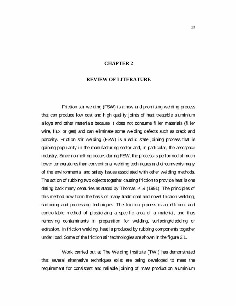
under load. Some of the friction stir technologies are shown in the figure 2.1.
Work carried out at The Welding Institute (TWI) has demonstrated
that several alternative techniques exist are being developed to meet the
requirement for consistent and reliable joining of mass production aluminium
14
alloy vehicle bodies. Three of these techniques (mechanical fasteners, lasers and
friction stir welding) are likely to make an impact on industrial processing over
the next 5 years. FSW could be applied in the manufacture of straight line welds
in sheet and extrusions as a low cost alternative to arc welding (e.g. In the
fabrication of truck floor walls). The development of robotized friction stir
welding heads could extend the range of applications into three dimensional
components.
Figure 2.1 - Schematic of friction stir technologies (Thomas et al 1991)
a) Radial friction welding, b) Friction extrusion, c) Friction hydro pillar
processing d) Friction plunge welding without containment shoulder
(a) (b)
(c) (d)

15
Mishra and Mahoney (2007) extended the FSW innovation to process
AA7075 and AA5083 in order to render them super plastic. They observed that
the grains obtained were recrystallized, equiaxed and homogeneous with average
grain sizes < 5 µm. They had high angles of misorientation ranging from 20° to
60°. They had also performed high temperature tensile testing in order to
understand the super plastic behaviour of Friction Stir Welded aluminium plates.
2.1 OPTIMIZATION OF MECHANICAL PROPERTIES OF WELDED
JOINTS
Welding processes can have various effects on the base metal. High
heat input may affect the mechanical properties of the base metal adversely.
Cracking occurs when a material is unable to resist the stresses that are applied
to it. The level of applied stress varies with the welding process. The joining
may change the mechanical properties of the base metal, consequently, this
factor must be considered in conjunction with usefulness after joining. The weld
or HAZ may be different from the base metal especially in FSW applications in
terms of hardness, strength, impact resistance, creep strength, and wear
resistance. The mechanical properties of welded joint are the major factors
deciding the welding quality. Knowledge of how welding parameters affect the
mechanical properties of welds is important. Consequently, the aim of the
designer is to optimize the mechanical properties in order to produce excellent
welded joints. For accomplishing this purpose different methods and approaches
have been developed and applied.
Flores (1998) found that the tensile properties of the joints made with
different welding conditions resulted in lowest tensile strength and ductility at
lower spindle speed for a given traverse speed. As the spindle speed increased,
both the strength and elongation improved, reaching a maximum before falling
again at high rotational speeds. It is clear that, in FSW, as the rotational speeds
increase, the heat input also increases. Hence, the tool rotation speed must be

16
optimized to attain maximum tensile properties of the FSW joints. As the
welding speed increases, the width of the strained region and the value of the
maximum strain decreases and the location of the maximum strain gradually
move to the retreating side from the advancing side of the joint. It is also
observed that the ultimate tensile strength decreases significantly when the
welding speed is increased. The softened area is narrower for higher welding
speeds than that for lower welding speeds (Lee et al 2004). Hence, the welding
speed must be optimized to attain maximum tensile properties of the FSW joints.
Liu and Fuji (2003) suggest that at low axial force, the formation of
non-symmetrical semi-circular features at the top surface of the weld shows poor
plasticization and consolidation of the material under the influence of the tool
shoulder. Though weld consolidation is good, formation of shear lips or flashes
with excessive height on both advancing side and retreating sides of the weld
line due to higher axial force resulted in excessive thinning of the metal in the
weld area yielding poor tensile properties. Hence, the axial force must be
optimized to attain maximum tensile properties.
Peel et al (2003) studied mechanical properties, microstructure and
residual stresses as a function of welding speed in aluminium AA 5083 friction
stir welds. It has been found that the weld properties have been dominated by the
thermal input rather than the mechanical deformation by the tool. The main
results suggest that the recrystallization results in the weld zone having a
considerably lower hardness and yield stress than the parent AA5083. During
tensile testing, almost all the plastic flow occurs within the recrystallized weld
zone. The peak longitudinal stresses increase as the traverse speed increases.
This increase is probably due to steeper thermal gradients during welding and
the reduced time for stress relaxation to occur. The base material is in an
extremely work hardened state and this is reflected in the hardness profiles.
17
Park et al (2004) evaluated the corrosion properties in a friction stir
welded 304 stainless steel. The degree of the sensitization was small in the heat
affected zone, but the advancing side of the stir zone was corroded significantly
because of the formation of the sigma phase. Austenitic stainless steels are
widely used in many industries utilizing high temperature components such as
heat exchangers and chemical reactors because of their good mechanical
properties at elevated temperatures and their excellent corrosion resistance.
Zhao et al (2005) found that the pin profile plays a crucial role in
material flow and, in turn, regulates the welding parameters of the FSW process.
Friction Stir Welds are characterized by well-defined weld nugget and flow
contours, almost spherical in shape, these contours are dependent on the tool
design and welding parameters and process conditions used (Attallah and Salem
2005).
Minton and Mynors (2006) demonstrated conventional milling
machine has been capable of performing FSW and producing reasonable welds
using a relatively stout tool to join 6.3 mm thick 6082-T6 aluminium. Lesser
quality welds were produced when joining 4.6 mm thick 6082-T6 aluminium.
Further work is required to establish if the welds in the 4.6 mm can be improved,
by enhancing the tool design, while ensuring the tool is sufficiently robust to
survive the process. The methodology is tested by producing same thickness
welds of 6.3 mm and 4.6 mm 6082-T6 aluminium sheets. The results from
micro-hardness profiles across the tool shoulder diameter are presented in
conjunction with tensile test results.
Fujii and Cri (2006) investigated the effect of the tool shape on the
mechanical properties and microstructures of 5 mm thick welded aluminium
plates. The simplest shape (column without threads), the ordinary shape (column
with threads) and the triangular prism shape probes were used to weld three

18
types of aluminium alloys. It has been found that for 1050-H24 whose
deformation resistance is very low, a columnar tool without threads produces
welds with the best mechanical properties. For 6061-T6 whose deformation
resistance is relatively low, the tool shape does not significantly affect the
microstructures and mechanical properties. For a low rotation speed (600 rpm),
the tool shape does not significantly affect the microstructures and mechanical
properties of the joints.
Cavaliere et al (2006) studied the effect of processing parameters on
mechanical and microstructural properties of AA 6056 joints produced by
Friction Stir Welding. Different samples were obtained by employing rotating
speeds of 500 rpm, 800 rpm and 1000 rpm and welding speeds of 40 mm/min,
56 mm/min and 80 mm/min. The mechanical properties of the joints were
evaluated by means of micro hardness (HV) and tensile tests at room
temperature.
Tveiten et al (2006) proposed some simple and flexible methods to
enhance the fatigue life of welded aluminium components. Besides enhancement
of the fatigue life, their proposed methods can easily be implemented in
manufacturing processes. The key element of the methods is to change residual
stresses from tension to compression at locations vulnerable to fatigue. This was
accomplished by mechanical prestressing using elastic pre deformation or by
thermal prestressing using induction heating. The specimens tested are welded
aluminium rectangular hollow section T-joints. Prior to fatigue testing, welding
FE simulations were carried out to verify the magnitude and pattern of the
residual stress fields (through process modeling). Fatigue testing was later
carried out on four different batches. One batch was produced using elastically
predeformed chords, two batches were treated by means of thermal prestressing
(induction heating). Based on statistical evaluation of S/N data it was reported
that the introduction of superimposed compressive stress fields significantly

19
improved fatigue life. Among the different batches, induction heating turned out
to be the most promising method with a fatigue strength improvement factor of
1.5 on stress, compared to ��as welded�� components.
Elangovan and Balasubramanian (2008a) studied the influence of tool
pin profile and tool shoulder diameter on the formation of friction stir processing
zone in AA2219 aluminium alloy. AA2219 aluminium alloy has gathered wide
acceptance in the fabrication of lightweight structures requiring a high strength-
to-weight ratio and good corrosion resistance. Five different tool pin profiles
(straight cylindrical, tapered cylindrical, threaded cylindrical, triangular and
square) with three different shoulder diameters were considered in their work to
fabricate the joints. The formation of FSP zone has been analyzed
macroscopically. Tensile properties of the joints have been evaluated and
correlated with the FSP zone formation. From the investigation they found that
the square pin profile tool with 18 mm shoulder diameter produced mechanically
sound and metallurgically defect free welds compared to other tool pin profiles.
Kulekci et al (2008) determined the effects of the tool pin diameter
and tool rotation on the fatigue behaviour of friction stir welded (FSW) lap
joints. FSW lap joints of AA 5754 aluminium alloy plates were produced by
means of a conventional semiautomatic milling machine. It was reported that
the: Increasing tool rotation for a fixed tool pin diameter reduces fatigue strength
of joints. Increasing tool pin diameter for a fixed tool rotation, decreases fatigue
strength of joints. In FSW lap joints, an optimisation between tool pin diameter,
tool rotation and tool traverse speed is needed to obtain better fatigue strength.
An index derived from tool rotation, traverse speed and tool geometry can be
used to identify optimum parameters in FSW. For the FSW lap joints of studied
material an index of 6 can be used to select the studied parameters.

20
Lakshminarayanan and Balasubramanian (2008) was used the
Taguchi parametric design and optimization approach. Taguchi approach was
applied to determine the most influential control factors which will yield better
tensile strength of the joints of friction stir welded RDE-40 aluminium alloy.
The effect of process parameters such as tool rotational speed, traverse speed
and axial force on tensile strength of friction stir welded RDE-40 aluminium
alloy is evaluated. Through the Taguchi parametric design approach, the
optimum levels of process parameters were determined. The results indicate that
the rotational speed, welding speed and axial force are the significant parameters
in deciding the tensile strength of the joint. The predicted optimal value of
tensile strength of friction stir welded RDE-40 aluminium alloy is 303 MPa.
Sarsilmaz and Caydas (2009) were experimentally investigated the
effect of friction-stir welding (FSW) parameters such as spindle rotational speed,
traverse speed, and stirrer geometry on mechanical properties of AA 1050/AA
5083 alloy couples. Ultimate tensile strength (UTS) and hardness of welded
joints were determined. The full factorial experimental design was conducted to
obtain the response measurements. It was reported that; the UTS and nugget
hardness increase with traverse speed. The UTS and nugget hardness decrease
with tool rotational speed. The most important factor on UTS was found as
traverse speed (71.62%), while the rotational speed was the second ranking
factor (10.59%) and stirrer geometry was the least (7.03%). The most important
factor on nugget hardness was found as traverse speed (72.57%), while the
rotational speed was second ranking factor (21.19%) and stirrer geometry was
the least (0.89%). The combinations of F3N1T2 and F3N1T1 were the optimal
welding conditions for UTS and hardness, respectively. The wideness of the
nugget was varying throughout the cross section of the welding zone. Ductile
fracture characterization was observed after tensile tests, as expected. The
fracture surfaces were covered with a broad population of microscopic voids of
different dimensions and shapes.

21
Jayaraman et al (2009) established an empirical relationship to predict
the optimum FSW process parameters to fabricate defect free joints with high
tensile strength from the known base metal properties of cast aluminium alloys.
The FSW process parameters such as tool rotation speed, welding speed and
axial force, etc. play a major role in deciding the weld quality. FSW Joints of
cast aluminium alloys A319, A356, and A413 were made by varying the FSW
process parameters and the optimum values were obtained. The tensile strength
and hardness of the cast aluminium alloys play a major role in deciding weld
quality of FSW joints. The empirical relationships established in this
investigation can be effectively used to predict the optimum FSW process
parameters to fabricate defect free joints with high tensile strength from the
known base metal properties of cast aluminium alloys.
Fazel-Najafabadi et al (2010) found that by adjusting the friction stir
welding parameters can achieve defect-free dissimilar lap joint of CP-Ti and 304
stainless steel. Titanium as a softer material was selected to be on the lap joint
top side. The joint stir zone was found to have two main regions; the dominant
fine dynamically recrystallized titanium grains in the upper region and a minor
composite type microstructure of fragments of 304 stainless steel in a matrix of
fine dynamically recrystallized titanium grains in the lower region. The stir zone
was separated from the 304 stainless steel side by an interface layer of Ti-Fe
based crystal structure. Joint shear strength was measured; a maximum failure
load of 73% of that of CP-Ti was achieved. This was associated with the
occurrence of fracture at the joint inter-metallic based interface. The failure load
value of the fabricated joints is related to the thickness of the inter-metallic
interface.
Arora et al (2010) were reported the work which was carried out in
adapted milling machine. Process forces (Fz and Fx) are critical for the selection
of a suitable milling machine. Axial thrust is affected significantly by shoulder

22
diameter and slightly by both tool rotational and welding speeds. Whereas, Fx is
affected strongly by welding speed and slightly by tool rotational speed and pin
diameter. Deterioration of tensile properties is experienced in case of welded
specimens as compared to the base material values. Tensile strength of the welds
is significantly affected by welding speed and shoulder diameter and slightly by
welding speed. Welding speed is the most significant parameter effecting
percentage elongation. Vickers hardness value is lowest in the nugget where
TEM studies showed the dissolution and coarsening of second phase particles.
Microstructure in nugget consisted of recrystallized grain structure with an
average decrease in grain size by a factor of 10. Microstructural changes in
TMAZ resulted from the combined effect of heat and deformation. GMA-weld
microstructure showed liquation in the PMZ of the weld. This led to the
embrittlement of grain boundaries and subsequent decrease in strength of the
GMA weld joint.
Shanmuga Sundaram and Murugan (2010) have analyzed dissimilar
FS welded joints, which are fabricated using five different tool pin profiles. With
the help of Central composite design with four parameters, five levels, and 31
runs, response surface method (RSM) is employed to develop the model.
Mathematical regression models were developed to predict the ultimate tensile
strength (UTS) and tensile elongation (TE) of the dissimilar friction stir welded
joints of aluminium alloys 2024-T6 and 5083-H321. Joints fabricated using
Tapered Hexagon tool pin profile have the highest tensile strength and tensile
elongation, whereas the Straight Cylinder tool pin profile have the lowest tensile
strength and tensile elongation, irrespective of the operating parameters. The
increase in tool rotational speed results in the decrease in tensile elongation,
whereas tensile elongation increases with increase in welding speed. The tensile
elongation decreases with increase in tool axial force.

23
Padmanaban and Balasubramanian (2010) developed an empirical
relationship which was used to predict the tensile strength of the laser beam
welded AZ31B magnesium alloy by incorporating process parameters such as
laser power, welding speed and focal position. Based on a three factor, three
levels, central composite face centered design matrix with full replication
technique, the empirical relationship can be used to predict the tensile strength of
laser beam welded AZ31B magnesium alloy joints at 95% confidence level. The
results indicate that the welding speed has the greatest influence on tensile
strength, followed by laser power and focal position.
Gopalakrishnan and Murugan (2011) studied the effective utilization
of Aluminium matrix composite (AMC) in particulate reinforced metal matrix
composite (MMC). It was based on not only its production but also on
fabrication methods. Aluminium matrix titanium carbide reinforced composite
(Al�TiCp) was produced in an inert atmosphere by indigenously developed
modified stir casting process with bottom pouring arrangement (3�7% TiC by
weight). Friction stir welding process (FSW) was employed to make weld joints.
The welding parameters such as axial force, welding speed, tool rotation speed,
percentage TiC addition etc., and profile of the tool were considered for analysis.
The FSW specimens without any post-weld heat treatment belonging to a
different set of parameters tested. This exhibited a high joint efficiency (most of
them ranging from 90% to 98%) with respect to the ultimate tensile strength of
the base material AA6061. It was reported from the analysis of the model that
the tool pin profile and the welding speed have a more significant effect on
tensile strength.
2.2 FRICTION STIR WELDING IN ALUMINUM ALLOYS
Liu et al (1997) studied microstructural aspects of the friction stir
welding of 6061-T6 aluminium. They stated that LM (Light Microscope) and
TEM (Transmission Electron Microscope) have been used to characterize the

24
microstructures in the FS weld zone and compared them with the original 6061-
T6 aluminium alloy plate. They have also measured the associated micro
hardness profile extending from the work piece and through the weld zone. A
series of butt welds and simulated welds in solid plate sections have been
conducted, at rotational speeds ranging from 300 rpm to 1000 rpm, and
translation (traverse) speeds of 0.15 cm/s to 0.25 cm/s. The hardened carbon
steel welding head pin was 0.63 cm in diameter and its length was 58 cm. The
main results have been obtained suggests that the FS weld zone in 6061-T6
aluminium is characterized by what appears to be a dynamic continuous
recrystallization microstructure. Second phase particles in the work piece were
essentially �stirred� into the weld zone where the residual hardness varies from
55 WHN near the top of the weld to 65 WHN near the bottom, in contrast to a
work piece hardness which varies between about 85 and 100 WHN. The weld
zone grain size averaged 10 µm in contrast to 100 µm for the work piece.
Rhodes et al (1997) studied the effects of FSW on microstructure of
7075 aluminium. They stated that the technique, based on friction heating at the
faying surfaces of two pieces to be joined, resulted in a joint created by interface
deformation, heat, and solid-state diffusion. The weld was characterized by a
recrystallized nugget having a 2-4 µm grain size.
Benavides et al (1999) studied low temperature FSW of 2024
aluminium. It has been demonstrated to involve dynamic recrystallization
producing ultra fine, equiaxed grain structures to facilitate super plastic
deformation. The 2024 Al alloy has been FS welded at a starting temperature of
-30 °C, and maximum weld zone temperatures did not exceed about 140 °C. The
residual FSW zone grain structure consisted of equiaxed, fine grains having a
uniform size of about 0.8 µm throughout. This compares with a central weld
zone grain size of about 10 µm in 2024 Al FSW at a starting temperature of
30°C, where the maximum weld zone temperature was measured to be 330°C.

25
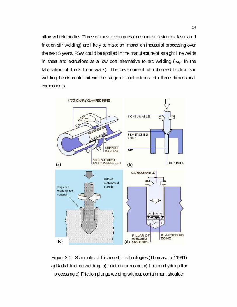
Figure 2.2 (a) and (b) shows the comparison between polished and etched FSW
cross sections of 2024 aluminium from room temperature (Figure 2.2 (a)) and
low temperature (Figure 2.2 (b)) welds. Figure2.2 (c) shows corresponding micro
hardness traverses along the reference lines indicated by the arrows in figure 2.2
(a) and (b).
Figure 2.2 � Microhardness Comparison (Benavides et al 1999)
(a) room temperature, (b) low temperature (c) microhardness - Open triangles
are room temperature data; solid circles are low temperature data.
Jata and semiatih (2000) studied a continuous dynamic
recrystallization during FSW of high strength aluminum alloys. They stated that
the stir welded plates of an Al-Li-Cu alloy (Al-1.8, Li-2.7, Cu-0.33, Mg-0.33,
Mn-0.04, Zr-0.7) have been used which had been hot rolled, homogenized,
solution heat treated, water quenched, and naturally aged prior to joining.
Optical microscopy (OM) has been performed to reveal the general
microstructure of the weld and the base metal.
Distance from weld zone center (mm)
160
150
140
130
120
110
100
90
80 -15 -10 -5 0 5 10 15
c

26
Chao et al (2001) studied the effect of FSW on dynamic properties of
AA2024-T3 and AA7075-T7351. Dynamic, compressive stress-strain curves
have been obtained of AA2024-T3 and AA7075- T7351 aluminium alloys and
their welds as produced by the FSW process. The experimental results that have
been obtained imply that the FSW reduces the yield stress of the weld metal to
below that of the base metal, both materials exhibit the strain rate effect. Yield
stresses of both base and FS welded material of AA2024-T3 exhibited rate
sensitivity. In addition, AA7075- T7351 base metal had some rate dependence.
However, no rate effect has been found for AA7075-T7351 FS welded material
up to the strain rate of 500/Sec. FSW reduced the yield stress of both AA2024-
T3 and AA7075-T7351 under both high strain rate and quasi-static loading
conditions.
Salem (2003) used friction stirring technology to join dynamically
recrystallized Al base thin sheets for structural parts brought about the need for
the macro and micro structural evolution and hardness characterization. FSW at
1000 rpm rotational speeds and 4.2 mm/s feeding rate have been successfully
performed with almost no grain growth for the welds. FSW augmented the
formation of fine equiaxed structure with high grain boundary misorientation
angles. The thermal and mechanical effect associated with FSW controlled the
particle size and distribution within the weld nugget and hence the
hardness profile. FSW has proven its capability of creating very fine grain
structures in the stirred region. This result from the intense plastic straining
associated with the movement of material from the front to the back of the
rotating pin. Because of the frictional effect as well as shear deformation, the
material undergoes localized heating and hence relative softening, which
facilitates plastic deformation.
Lee et al (2003) studied the improvement of mechanical properties of
Friction Stir welded A356 Al alloy with 87 mm/min, 127 mm/min, 187 mm/min,

27
and 267 mm/min FSW speeds. The optical micro-structural changes of the stir
zone (SZ) with welding speeds were discussed. The Si particles have been
homogeneously distributed in the whole SZ regardless of the welding speeds, but
the portion of the Si particles in the SZ decreases as welding speed increases.
The hardness of the SZ showed more uniform values than that of the BM due to
finer and uniformly dispersed Si particles. The transverse ultimate and yield
strength had similar values with the BM. All the specimens have been fractured
at the unaffected BM. The longitudinal ultimate tensile strength has 178 MPa,
which is a 20% improvement on that of the BM, and the yield strength also
shows higher value. The mechanical properties of the SZ have been improved by
the dispersed Si particles and the homogeneous microstructure compared with
that of BM.
Dickerson et al (2003) studied a weld marker technique for flow
visualization in friction stir welding. They stated that the technique was based on
the use of a marker material that had been redistributed during welding. Copper
strips (0.1 mm thick) had been used as markers. After welding various methods
have been used to investigate the marker movement including, radiography,
tomography and metallurgical sectioning.
Wert (2003) studied microstructures of FSW joints between an
aluminium-base metal matrix composite and a monolithic aluminium alloy. They
stated that microstructures in FS welds between monolithic AA2024 and
AA2014 reinforced with 20 vol.% particulate Al2O3 reveal that the narrowest
layers of each material are about 0.1 mm thick. Thus, each material retains its
identity in the weld zone and convoluted macro interfaces. When the harder
material was on the advancing side of the tool the macro interface span is larger,
this can be understood qualitatively by considering how the relative hardness
affects material transport. The welds also exhibit eutectic melting. The liquid
phase has the traditional form of grain boundary films in the thermo-mechanical

28
process zone. Particle strings and fragmentation fracture zones have been
observed, these may also result from eutectic melting.
Sato et al (2004) studied a friction stir welding of ultra fine grained
Al alloy 1100 produced by accumulative roll bonding (ARBed). FSW resulted in
the reproduction of fine grains in the stir zone and small growth of the ultra fine
grains of the ARBed material just outside the stir zone. FSW suppressed large
reductions of hardness in the ARBed material, although the stir zone and the
TMAZ experienced small reductions of hardness due to dynamic
recrystallization and recovery. Consequently, FSW effectively prevented the
softening in the ARBed alloy.
Fonda et al (2004) studied a development of grain structure during
friction stir welding. They stated that a stop action friction stir weld has been
prepared in Al�Li 2195 to �freeze in� the dynamic deformation field
surrounding the FSW tool. Analysis of a plan view section of this weld revealed
important new details of the grain structure evolution and texture development
occurring around the FSW tool. Bands of refined grains developed ahead of the
fully refined region, likely reflecting different relative stabilities of the original
grain orientations to the applied deformation. Fine sub grains were formed in
response to the predominantly simple shear deformation field and gradually
developed greater misorientations to produce the refined grains were observed
adjacent to the tool.
Sutton et al (2004) studied a banded microstructure in 2024-T351 and
2524-T351 aluminium friction stir welds for mechanical characterization. They
stated that a series of micro mechanical experiments have been performed to
quantify the FSW process affects the material response within the periodic
bands. Micromechanical studies employed sectioning of small samples and
micro tensile testing using digital image correlation to quantify the local stress�

29
strain variations in the banded region. Results indicate that the two types of
bands in 2024-T351 and 2524-T351 aluminium FSW joints have different
hardening rates with the particle-rich bands having the higher strain hardening
exponent, exhibit a periodic variation in micro hardness across the bands and the
individual bands in each material have the same initial yield stress.
Cavaliere et al (2006) studied mechanical and microstructural
behavior of 2024�7075 aluminium alloy sheets joined by friction stir welding.
The resulted microstructure due to the FSW process had been studied by
employing OM and SEM either one as welded specimens and on the tests
specimen after rupture occurred. The main results have been obtained that the
dissimilar 2024 and 7075 aluminium alloy in the form of 2.5 mm thick sheets
have been successfully joined by friction stir welding. The specimen fracture
surfaces after testing have been deeply analyzed by using a FEGSEM
microscope, revealing the defects topology and location after the friction stirring
process and the microscopic mechanisms occurred during high stress
deformations and final failure.
Scialpi et al (2007) studied the influence of shoulder geometry on
microstructure and mechanical properties of friction stir welded 6082 aluminium
alloy. In this work, they considered three shoulder geometries and AA 6082 T6
1.5 mm thick sheets for investigation. The welding process was carried out
rotating the tool at 1810 rpm and at a feed rate of 460 mm/min. By visual
inspection the crown and root quality has been evaluated. The tools with
dissimilar shoulders produce very different crown quality. The bead obtained by
the TFC tool (fillet + cavity) was characterized by a smooth surface and very
little flash, which was produced but it was removed during the process as a
continuous chip. TFC tool crown can be considered the best in terms of crown
quality. The resulting microstructure was widely investigated by optical
microscopy putting out the influence of shoulder geometry on the nugget grain

30
size. In the transverse tensile test the three joints showed good strength and non-
considerable differences were observed, while great differences were observed
in the longitudinal tensile tests of the stirred zone, because TFS (fillet + scroll)
and TFC showed a higher and higher strength and elongation respect to the TF
(only fillet). With 460 mm/min and 1810 rpm, TFC can be considered the best
tool because the combination of fillet and cavity increases the longitudinal and
transverse strength of the joint and provide the best crown surface.
Moreira et al (2008) studied Fatigue crack growth in friction stir
welds of 6082-T6 and 6061-T6 aluminium alloys. In this work, a comparative
study between fatigue crack growth behaviour of friction stir welds of 6082-T6
and 6061-T6 aluminium alloys was carried out. Fatigue crack growth curves
were determined for cracks growing in different locations of the weldments,
including the base material, the heat affected zone and the welded material.
Generally, friction stir material exhibited lower strength and ductility properties
than the base material. However, an enhanced crack propagation resistance was
observed in the welded material. The 6082-T6 and 6061-T6 base materials
exhibited very similar crack propagation behaviour. On the other hand the
friction stir 6061-T6 material showed lower crack propagation rates than
corresponding 6082-T6 friction stir material.
Scialpi et al (2008) underwent mechanical analysis of ultra-thin
friction stir welding joined sheets with dissimilar and similar materials. A deep
analysis of the mechanical behavior of two different Al alloys joined by FSW
technique was carried out. The analysis included both similar and dissimilar joint
configurations in 6082-T6 and 2024-T3 alloy sheets. An important aspect of the
study was represented by the plate thickness, which was limited to only 0.8 mm.
For this reason, joining process can be correctly classified as FSW. The resulting
microstructure has been investigated by optical microscopy and the nugget zone
has shown a equiaxed fine grain structure with an estimated grain size < 3 µm.

31
Elangovan et al (2008) had been made investigation to understand the
effect of axial force and tool pin profiles on FSP zone formation in AA6061
aluminium alloy. Five different tool pin profiles (straight cylindrical, tapered
cylindrical, threaded cylindrical, triangular and square) have been used to
fabricate the joints at three different axial force levels. Tensile properties of the
joints have been evaluated and correlated with the FSP zone formation. From
this investigation it is found that the square tool pin profile produces
mechanically sound and metallurgically defect free welds compared to other tool
pin profiles. An axial force of 7 kN produces a defect-free FSP region,
irrespective of tool pin profiles. Fifteen joints were fabricated in this
investigation; the joint fabricated using the square pin profiled tool at an axial
force of 7 kN showed superior tensile properties. The formation of FSP zone has
been analysed macroscopically. A defect-free FSP region, smaller grains with
uniformly distributed finer strengthening precipitates in FSP region and higher
hardness are the reasons for superior tensile properties of the above joints.
Karthikeyan et al (2009) studied the mechanical property and
microstructural changes during friction stir processing of cast aluminium 2285
alloy. On friction stir processing, the mechanical properties and microstructure
of cast aluminium Al 2285 alloy was altered substantially. It was observed
around thirty percent improvement in yield and tensile strengths over the parent
material. The ductility values too increased around four fold on friction stir
processing of parent material. Increase in tool rotational speed for a feed
enhances the mechanical properties. Samples processed with a tool transfer feed
of 12 mm/min and 1800 rpm rotational speed were found to have better
mechanical properties. The defects present in cast aluminium alloys were
eliminated in the area of processing.
Elangovan et al (2009) developed a mathematical model to predict
tensile strength of the friction stir welded AA6061 aluminium alloy by

32
incorporating FSW process parameters. Four factors, five levels central
composite design has been used to minimize number of experimental conditions.
Response surface method (RSM) has been used to develop the model. Statistical
tools such as analysis of variance (ANOVA), student�s t-test, correlation co-
efficient etc. have been used to validate the developed model. The developed
mathematical model can be effectively used to predict the tensile strength of
FSW joints at 95% confidence level. A mathematical model has been developed
to predict the tensile strength of friction stir welded AA6061 aluminium alloy
joints by incorporating welding parameters and tool profiles using statistical
tools such as design of experiments, analysis of variance and regression analysis.
The joints fabricated using square pin profiled tool with a rotational speed of
1200 rpm, welding speed of 1.25 mm/s and axial force of 7 kN exhibited
superior tensile properties compared to other joints.
Rajakumar et al (2011) developed empirical relationships to estimate
the grain size and hardness of weld nugget of friction stir welded AA 6061-T6
aluminium alloy joints incorporating FSW tool and process parameters. A linear
regression equation was established between grain size and hardness of the weld
nugget of friction stir welded AA6061-T6 aluminium alloy joints. The
developed relationships can be effectively used to predict the grain size and
hardness of friction stir welded AA6061-T6 aluminium alloy joints within the
range of parameters.
2.3 DOUBLE SIDE FRICTION STIR WELDING
Klingensmith et al (2005) described the formation of different
microstructural zones in friction stir welded superaustenitic stainless steel (AL-
6XN) using results from various characterization techniques. The microstructure
of AL-6XN plates joined via a double-sided friction stir weld has been
investigated. The microstructural zones that develop during friction stir welding
(FSW) reflect decreasing strains and less severe thermal cycles with increasing

33
distance from the weld centerline. The nugget has a refined structure of equiaxed
grains as a result of the extreme strain and temperatures experienced during
welding. Several features were seen within the nugget, one of the most
prominent being a steady stream of tungsten inclusions created by accelerating
tool wear. The heat-affected zone consists of a mixture of relatively large
austenite grains and smaller recrystallized grains present at grain boundaries.
These fine grains were shown to be austenite and no evidence of sigma phase in
this region was apparent. The thermo mechanically affected zone, located
between the nugget and heat-affected zone, shows a microstructural transition
from the completely refined structure to a structure very similar to the base
metal. Unlike fusion welding, micro segregation has been avoided during FSW.
Due to the changing microstructure from base metal to the weld zone, there are
corresponding changes in hardness. Moving toward the centerline from the base
metal, hardness increases due to refinement of grain size.
Aarici and Sinmaz (2005) studied the effects of double passes of the
tool on friction stir welding of polyethylene. They welded PP sheets with a
single pass of the tool. It created the root defect, which was defined as an area at
the bottom of the joint that is not welded. The bottom of each joint was not
stirred, and thus left unwelded. This defect was responsible for all tensile and
bending failure. In the first pass the plate was welded approximately half of the
material thickness, and then turned back and clamped the sample for the second
pass of the tool. After the second pass of the tool, no root defect appeared.
2.4 COMPARISON BETWEEN MIG, TIG AND FSW
Ericsson et al (2003) studied the influence of welding speed on the
fatigue strength of friction stir welds, and compared with MIG and TIG. They
investigated the influence of welding speed on fatigue strength of FS welds and
compared the fatigue results with results for conventional arc welding methods.
The Al�Mg�Si alloy 6082 was FS welded in the T6 and T4 temper conditions,
34
MIG-pulse and TIG welded in T6. The T4-welded material has been subjected to
a post weld ageing treatment. They have been concluded that at a significantly
lower welding speed, the fatigue performance has been improved possibly due to
the increased amount of heat supplied to the weld per unit length. The MIG
pulse and TIG welds showed lower static and dynamic strength than the FSW.
The TIG welds had better fatigue performance than the MIG pulse welds. The
experimental results have been obtained that the fatigue strength of FS welded
Al�Mg�Si alloy 6082 is higher than that of MIG pulse and TIG welds of the
same material. The TIG welds show better fatigue performance than MIG.
Squillace et al (2004) carried out an experimental investigation on
microstructure and corrosion resistance of weld butt joints of AA 2024-T3. They
considered two different welding processes: TIG and FSW. Micro-hardness
measurements allow pointing out a general decay of mechanical properties of
TIG joints, mainly due to the high temperatures experienced by the material. In
FSW joint, instead, lower temperatures involved in the process and severe
plastic deformations induced by tool motion causes decay of mechanical
properties in weld zone. Polarization curve tests and electrochemical impedance
spectroscopy, were assessed a generalized nobler behaviour of weld bead with
respect to parent alloy. The differences between the three examined zones are
not so evident as in TIG joint; retreating zone shows a behaviour nobler than
advancing one in FSW joint.
Lakshminarayanan et al (2009) evaluated the mechanical properties
of GMAW, GTAW and FSW joints of AA6061 aluminum alloy. The joints
fabricated by FSW process exhibited higher strength values and the
enhancement in strength value is approximately 34% compared to GMAW
joints, and 15% compared to GTAW joints. Hardness is lower in the weld metal
(WM) region compared to the HAZ and BM regions irrespective of welding
technique. Very low hardness is recorded in the GMAW joints (58 VHN) and

35
the maximum hardness is recorded in the FSW joints (85 VHN). The formation
of fine, equiaxed grains and uniformly distributed, very fine strengthening
precipitates in the weld region are the reasons for superior tensile properties of
FSW joints compared to GTAW and GMAW joints.
2.5 MICROSTRUCTURE AND MICROHARDNESS OF FSW
Li et al (1998) studied flow visualization and residual microstructures
associated with the friction stir welding of 2024 aluminium to 6061 aluminium.
They stated that the FSW of 0.6 cm plates of 2024 AA to 6061 AA was
characterized by residual, equiaxed grains within the weld zone having average
sizes ranging from 1 µm to 15 µm, exhibiting grain growth from dynamically
recrystallized grains which provide a mechanism for super plastic flow,
producing intercalated, lamellar like flow patterns. These flow patterns are
visualized by differential etching of the 2024 AA producing contrast relative to
6061 AA. The equiaxed grain and sub grain microstructures have been observed
to vary according to estimated temperature profiles referenced to the rotating
tool axis. Dislocation spirals and loops have been also observed in the 2024 AA
intercalation regions within the weld zones at higher speeds (> 800 rpm)
corresponding to slightly elevated temperatures introducing dislocation climb,
and residual micro hardness profiles follow micro structural variations which
result in a 40% reduction in the 6061 AA work piece micro hardness and a 50%
reduction in the 2024 AA work piece micro hardness just outside the FSW zone.
Harris and Norman�s (2003) suggested that the variation of the micro-
hardness values in the welded area and parent material was due to the difference
between the microstructures of the base alloy and weld zone. As compared to
base material, considerable softening occurs throughout the weld zone due to the
elimination of strain-hardening effect by dynamic recrystallisation.

36
Chen and Kovacevic (2004) studied joining of AA 6061 alloy to AISI
1018 steel by the combined effects of fusion and solid state welding. The process
has been derived from FSW but with an adjustable offset of the probe location
with respect to the butt line. Metallographic studies by OM, EDM, and the
utilization of the X-ray diffraction technique have been conducted. It has been
found that the intermetallic phases Al13Fe4 and Al5Fe2 exist in the weld zone.
Jones et al (2005) reported the correlation between microstructure and
micro hardness in a friction stir welded 2024 aluminium alloy. They discussed
that: the HAZ on the retreating side of a friction stir welded 2024-T351
aluminium alloy has been found to contain two distinct hardness minima on
either side of a maximum. The inner hardness minimum close to the TMAZ was
found to be due to coarsening and over aging of the S phase occurring during the
thermal cycle. The outer hardness minimum was thought to be due to the
dissolution of the very fine S phase occurring towards the outer edge of the
HAZ. The hardness maximum inter adjacent to these two minima was seen to be
due to the presence of very fine S phase precipitates, and was likely to be a result
of optimum aging conditions being achieved. The nugget zone was found to be
typically fine grained and contained complex dislocation structures within the
grains, together with evidence that fine scale S and larger X phase precipitation
had occurred from a solutionized state.
Shusheng et al (2007) studied the influence of zigzag-curve defect on
the fatigue properties of friction stir welds in 7075-T6 Al alloy. The weld nugget
was characterized by a recrystallized, fine equiaxed grain structure because the
precipitates have fully or partially gone into solution and reprecipitation during
the joining process.
Zadpoor et al (2008) investigated the microstructure of friction stir
welded tailor-made blanks. Onion ring structures can be seen in microstructures.

37
The stirring zone tends to have a heterogeneous texture. A vortex-shape zone,
which is coincident with the chemical mixing zone, was observed. The
microstructures of the base metals are typical for the cold-rolled aluminium
sheets with elongated grains in the rolling direction. The grain size was not the
same for different thicknesses of the same material. The size of the WN was
found in all cases to be slightly greater than the pin diameter (Reynolds 2000).
The size of the TMAZ was measured to be about 0.4 µm � 0.5 µm for
configuration number 1�4. For configuration number 5, the size of the TMAZ
was very small. The classic �onion rings� structure has a different morphology
(asymmetric vortex-shaped) for the dissimilar-alloy configuration. The
asymmetric vortex-shaped region was slightly to the right of the weld centerline
and coincides with the chemical mixing zone. One of the features of the onion
rings most often referred to is the decreasing distance between the rings when
progressing from the center towards the periphery (Krishnan 2002).
First, Biallas et al (1999) suggests that the onion rings were generated
due to the reflection of the material flow from the cooler wall of the heat
affected zone, creating the necessity for thorough mixing of the two sides of the
weld. A second hypothesis was provided by Threadgill (1999) and Krishnan
(2002) who argue that the onion rings are related to the forward motion of the
welding tool making FSW simply an extrusion process in which a number of
semi-cylinders are extruded by the welding tool (Krishnan 2002). The results of
the EDS analysis show a very narrow chemical mixing zone, smaller than what
expected based on the reflection of the material. The material behind the tool
would have to be in the fluid state contradicting the observations reviewed
(Mishra and Ma 2005). In fact, the FSW process is mostly considered (Arbegast
et al 2003) to work as a localized cold-working process combining conventional
metal working zones of pre-heat, plastic, extrusion, forging, and cool-down.

38
The welded sheets from the same-alloy configurations have two
dominant grain orientations, one dominating in the advancing side and the other
in the retreating side. This suggests that the large plastic deformations result in a
preferred grain orientation. Quantitative texture studies of the FS welds have
shown that the effects of the tool shoulder on texture evolution are limited to the
upper surface of the sheet and the texture evolution in the weld nugget is largely
due to the pin motion (Sato et al 2001). It was shown that the measured texture
at the weld centerline is mainly composed of a shear component (Sato et al
2001). Due to different velocity fields, in the advancing side, the shear
component rotates around the pin axis in the counter-clockwise direction and on
the retreating side; the shear component rotates around the pin axis but in the
clockwise direction resulting in two different orientations on either side of the
weld (Sato et al 2001).
The dominant grain orientation is significantly different from
configuration number 4. The grain orientation distribution is much more
complicated. In the advancing side (2024), no dominant grain orientation can be
recognized but on the retreating side there are sub-areas with a dominant grain
orientation. This is in agreement with the findings of Prangnell and Heason
(2005). The rings have apparently resulted from the periodic flow of material
around the rear of the pin (Prangnell and Heason 2005, Hassan et al 2003).
The spacing between onion rings is approximately equal to the tool
advancement per revolution. Another interesting feature of the welds is the
gradient in grain orientation of single rings. The orientation of the grains, within
the ring, gradually changes progressing from the advancing side to the retreating
side. The heterogeneous nature of the texture as well as the ring-shape structure
of the texture is in agreement with the findings of previous researchers (Field et
al 2001). In summary, for the same-alloy configurations, the basic
microstructural features of the weld zone are not much affected when the

39
thickness ratio of the sheet changes. Furthermore, the microstructural features of
the weld zone for the different-alloy configuration are different from those of the
same-alloy configurations.
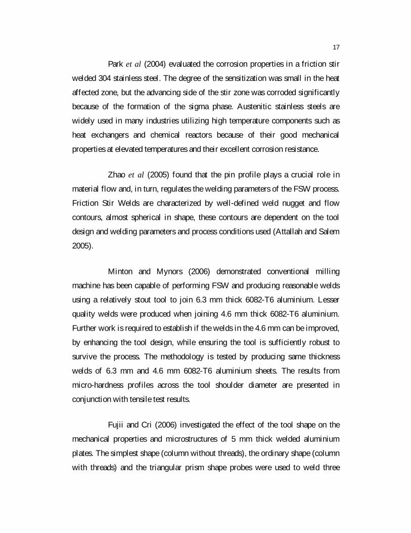
Figure 2.3 - FS welded AA6082-T6 joint microstructure (Moreira et al 2009)
(a) stirred material limit microstructure; (b) nugget structure detail,
microstructure; (c) base material microstructure
Moreira et al (2009) characterized metallurgically the FSW joints of
AA6061-T6 with AA6082-T6. The Figure 2.3 (a) represents the transition of the
stirred material to non-stirred material, the flow patterns can be easily identified
on the left side of the microstructure. Figure 2.3 (b), nugget microstructure
detail, can be directly compared with figure 2.3 (c) which represents its base
material.
Sakthivel et al (2009) reported from their investigation that the
microstructure of the weld nugget consists of fine equiaxed grains. These grains
are more homogeneous at lower welding speed than at higher welding speed.
Similarly, size of the weld zone becomes wider when decreasing the traverse
(a) (b)
(c)

40
speed as a result of a large amount of frictional heat and easy material flow.
Weld zone hardness is decreasing as compared to the parent metal, but the
hardness slightly increases with the increase of welding speed. The ultimate
tensile strength is observed to increase when decreasing the traverse speed.
However, the best mechanical properties are obtained at lower traverse speed
presumably due to the occurrence of homogeneous grains and higher heat input.
2.6 MODELING OF FRICTION STIR WELDING PROCESS
2.6.1 Thermal modeling
The heat generated and the temperature history during the FSW
process is the first step towards understanding the thermo-mechanical interaction
taking place during the welding process. The initial modeling approaches
focused on approximate estimation of heat generated during the FSW process.
Gould and Feng (1999) developed a preliminary thermal model to predict the
temperatures of friction stir welds using the Rosenthal (1946) and Rykalin
(1974) equations to describe a moving heat source. The heat input was described
as a function of process parameters such as tool rpm and force on the tool.
Chao et al (2003) formulated a boundary value problem for tool and
work piece in order to study the heat transfer in friction stir welding. They
determined the frictional heat flux from the measured transient temperature
fields obtained in the finite element analyses. In an attempt to predict the flow of
material around the tool, Colegrove (2000) presented a finite element based
thermal model of FSW. Their model included the backing plate and the tool. In
their work, the heat input was fitted through an iterative process for verification
between the modeled and experimental values.
An input torque based thermal model for prediction of temperature in
friction stir welds of Al-6061-T6 alloy was developed by Khandkar et al (2003).

41
In their model, the heat generated by tool rotation and linear traverse of shoulder
and pin, has been correlated with actual machine power input. This estimated
heat was applied as a moving heat to obtain the temperature distribution across
the weld.
Song and Kovacevic (2004) proposed a coupled heat transfer model
of both the tool and the work piece for FSW to include the tool penetration and
pulling out phase. A moving coordinate was adopted to reduce the difficulty of
modeling the heat generation due to the movement of the tool pin. The finite
difference method was used for solving the control equations and the results
obtained were in good agreement with the experimental results.
Vilaca et al (2005) developed an analytical thermal model for
simulation of friction stir welding process. The model included a simulation of
the asymmetric heat field under the tool shoulder resulting from viscous and
interfacial friction dissipation. The analytical model also considered the
influence of hot and cold FSW conditions into the heat flow around the tool.
The focus of all the thermal models was to understand the process of
heat generation and to predict the temperature distribution in the work piece and
tool. A thermal model forms the basis for the development of mechanical and
microstructural models.
2.6.2 Thermo-mechanical modelling
In order to estimate residual stress and distortions in work piece
resulting from the welding process, thermo-mechanical models were developed
and studied. One of the first thermo-mechanical models for FSW was studied by
Chao and Qi (1998). A decoupled heat transfer and a subsequent thermo-
mechanical analysis of Al 6061-T6 was used in their study. Heat generated from
friction between tool shoulder and work piece was implemented as the heat

42
input. The empirical equation for calculating the heat input to the work piece is
given by equation (2.1).
Q(r) = 3Qt / 2 (ro3 ri
3) (2.1)
Where Q(r) is the rate of heat input, ro and ri are the radii of the
shoulder and the nib of the pin tool, and Qt is the total rate of heat input to the
work piece expressed as shown in equation (2.2).
Qt = F (ro2+rori+ri
2) / 45 (ro+ri) (2.2)
Where, is the tool rotational speed, is the frictional coefficient,
and F is the downward force. The total heat input and heat transfer coefficient
were estimated by fitting the measured temperature data with the analytical
model by a trial and error approach. The temperatures thus obtained from the
analysis were used to determine the residual stress retained in the friction stir
welds. The maximum residual stresses were reported to be 30% of the yield
strength of the material.
Chen and Kovacevic (2003) proposed a three dimensional finite
element analysis model to study the thermal history and thermomechanical
process in butt welding of aluminium alloy 6061-T6. The model incorporated the
mechanical reaction of the tool and thermomechanical processes of the welded
material. The friction between the material, the probe and the shoulder was
included in the heat source. X-ray diffraction technique was used to measure the
residual stresses developed on the plate and the measured results were used to
validate the efficiency of the proposed model. From the study, it was reported
that fixturing release to the welded plates affected the stress distribution of the
weld.

43
Song and Kovacevic (2003) presented a three-dimensional heat
transfer model for friction stir welding (FSW). A moving coordinate was
introduced to reduce the difficulty of modelling the moving tool. Heat input
from the tool shoulder and the tool pin were considered in the model. The finite
difference method was applied in solving the control equations. A non-uniform
grid mesh was generated for the calculation. FSW experiments have been done
to validate the calculated results. The calculated results were in good agreement
with the experimental results. The calculated result also showed that preheat to
the work piece were beneficial to FSW.
Staron et al (2004) conducted an experimental study on residual stress
states in FSW joints in 6.3 mm and 3.2 mm thick AA 2024 sheets that had been
welded under mechanical tension. They were successful in reducing the tensile
residual stress in the weld zone by induction of large compressive stresses
through mechanical tension.
Zhu and Chao (2004) presented three-dimensional nonlinear thermal
and thermo-mechanical simulations using finite element analysis code
WELDSIM on 304L stainless steel friction stir welded plates. Initially, a heat
transfer problem was formulated as a standard boundary value problem and was
solved using the inverse analysis approach. The total heat input and heat transfer
coefficient were estimated by fitting the measured temperature data with the
analytical model. Later, the transient temperature outputs from the first stage
were used to determine residual stresses in the welded plates using a three-
dimensional elasto plastic thermo-mechanical model.
Convection and radiation were assumed to be responsible for heat
loss to the ambient on the surface. Their model provided a good match between
experimental and predicted results. They reported that the residual stress on the
welds after fixture release decreased significantly as compared to those before

44
fixture release. They also reported that about 50% of the total mechanical energy
developed by FSW machine was utilized in raising the temperature of the work
piece.
Soundararajan et al (2005) developed a finite element thermo-
mechanical model with mechanical tool loading considering a uniform value for
contact conductance and used for predicting the stress at work piece and backing
plate interface. The non-uniform contact conductance was defined from pressure
distribution contours and was used in predicting the temperatures in the thermal
model. The thermo-mechanical model was then used in predicting the developed
stresses. Khandkar et al (2006) developed coupled finite element models to
predict residual stress in AA-2024, AA-6061 and SS 304L friction stir welds. In
their models, the temperature history predicted by the thermal model was
sequentially coupled to a mechanical model to assess the residual thermal
stresses developed during the welding. It was found that clamping constraints
and their locations had significant localized effects on the stress components in
the unaffected base metal beyond the heat-affected zone.
Feng et al (2007) presented a more detailed thermal-metallurgical-
mechanical model to study the microstructure changes and their effects on
residual stress distribution in friction stir welding of Al6061-T6. In their
approach, the first stage involved a transient nonlinear heat flow analysis to
determine the temperature distribution. The frictional heating in the thin layer
near the interface was treated as a surface heat generation term, Q, which was
estimated by the equation (2.3).
Q = 2 F r / 60 (ro2 ri
2) (2.3)
Where F is the downward force, is the rotational speed, is the
process efficiency, is the interpretive coefficient of friction, and ri and ro the
radii of the pin and the shoulder respectively. In the second stage, using the

45
temperature history of the thermal model as input, the metallurgical calculations
were performed in the mechanical analysis as a part of the material constitutive
definition subroutine. It was reported that residual stresses had a strong
dependence on the welding speed.
Li et al (2007) presented a semi coupled thermo-mechanical finite
element model containing both thermal load and mechanical load. Their model
included an auto adapting heat source in the thermal model and fixtures were
included in the mechanical model. They reported that in the case of 2024-T6
alloy, stresses at the retreating side of the weld were smaller than those on the
advancing side.
Bastier et al (2008) used the computational fluid dynamics package to
estimate the material flow and temperature field in 7050 aluminium alloy. They
used the results to estimate residual state induced in friction stir welding process
based on elasto-visco plastic constitutive law. They also reported from the
parametric study that the welding speed and rotational speed had an influence on
the level of residual stresses and distortions developed during welding.
Hwang et al (2008) conducted an experiment in friction stir welding
(FSW) with butt joining configuration of 6061-T6 aluminium alloy. The
temperature around the joint line was predicted by regression analysis with the
experimental data. From the regression analysis they reported that the
temperatures inside the pin can be regarded as a uniform distribution and that the
heat transfer starts from the rim of the pin to the edge of the workpiece,
approximately following a second-order polynomial equation. The appropriate
temperatures for a successful FSW process are between 365ºC and 390ºC. The
temperatures on the advancing side were slightly higher than those on the
retreating side. The tensile strength and the hardness at the thermo-mechanically
affected zone (TMAZ) are about one-half of the base metals. These experimental

46
results and the process control of temperature histories can offer useful
knowledge of an FSW process of butt joining.
Dattoma et al (2009) evaluated the residual stress fields in similar and
dissimilar joints in 2024-T3 and 6082-T6 Aluminum alloy using hole-drill
method. The findings from their study showed that in thicker joints very high
longitudinal stresses were present and adequate shoulder geometries resulted in
reduction of residual stress values.
Rajamanickam et al (2009) investigated the effect of process
parameters such as tool rotation and weld speed on temperature distribution and
mechanical properties of aluminum alloy 2014 joined by friction stir welding. A
three dimensional transient thermal model using finite element code ANSYS
was developed and experimentally validated to quantify the thermal history. To
systematically study the influence of input parameters, nine experiments based
on full factorial design were performed. Samples were prepared and welded by
varying input parameters such as tool rotation and weld speed. The analysis of
variance (ANOVA) was employed to investigate the effect of input parameters
on thermal history and mechanical properties of the weld. Temperature
measurements and analysis of variance (ANOVA) indicated that the temperature
under the tool was strongly dependent on the tool rotation speed than the weld
speed. The results also indicated that weld speed could be the main input
parameter that had the highest statistical influence on mechanical properties.
Fratini et al (2009) studied the influence of material characteristics on
plastomechanics of the FSW process for T-joints. Welding of T-joints were very
challenging due to thin walls, poor location of the rib�web interface and the
requirements for corner-fillets. They investigated the FSW of T-joints of two
popular aluminium alloys, i.e. 2024-T4 and 6082-T6, and the role played by the
material characteristics on joining. First, an experimental study was carried out

47
with specially designed fixture to determine the effect of process conditions.
Then, the joints were metallurgically and mechanically evaluated. Finally using
a numerical model of the process previously developed by the authors, the
thermal and plastic flow fields for the two alloys were calculated and compared.
It was found that the material dependent thermal and plastic fields affect the
state of TMAZ, HAZ and nugget-region in the joint and that the low-strength
high-work hardening alloy 6082 provided a much better joint integrity than the
higher-strength low-hardening 2024 primarily due to the greater penetration of
the plastic zone in the former.
Peel et al (2003) investigated the microstructure, mechanical
properties and residual stress as a function of welding speed for AA 5083
friction stir welds. They reported that the weld properties were characterized by
thermal input rather than the mechanical deformation by the tool. They also
reported that with the increase in traverse speed the weld zone decreases, while
the peak longitudinal stress increases.
Zhang and Zhang (2007) presented the three dimensional finite
element simulations based on solid mechanics. This has been carried out to
understand the material flow, the deformations of material, and the formations of
weld zones in the friction stir welding process. Comparisons with the
experiments suggest that the models established in this paper can adequately
help the understanding of the mechanisms of the friction stir welding process.
The results under different process parameters can be meaningful to help
obtaining better quality of the friction stir welds. Numerical results indicate that
the tangent flow constitutes the major part in the material flow. The shoulder can
accelerate the material flow on the top half of the friction stir weld. The
distribution of the equivalent plastic strain can correlate well with the
microstructure zones. Increasing the angular velocity of the pin, the material in
the nugget zone can be more fully mixed, which improves the joining quality of

48
the two welding plates. The increase of speeds, including the rotational speed
and the translational speed, can both accelerate the material flow, especially in
front of the pin on the retreating side where the fastest material flow occurs. The
contact pressure on the pin-plate interface is decreased with the increase of the
angular velocity.
Zhang et al (2009) have been studied the influences of the shoulder
sizes on temperature distributions and material deformations in FSW by using a
fully coupled thermo-mechanical model. It was reported that the maximum
temperature can be increased with the increase of the shoulder size. The
temperature distribution under the shoulder becomes more uniform with the
increase of the shoulder size. The increase of the shoulder diameter can lead to
the increase of the efficient power for FSW process. The deformations of
material on the advancing side are slightly higher than that on the retreating side.
The temperature variation is the main factor for controlling the grain growth near
the welding line. But, the recrystallization process can be dominated by the
material deformations near the border of the stirring zone.
Rajamanickam et al (2009) detailed the non-linear thermo-mechanical
finite element (NLTMFE) model and studied the thermal history and stress
distribution in FSW of aluminium alloy. They considered three welding cases
with tool rotational speeds of 355 rpm, 710 rpm and 1120 rpm and reported that
the thermal modeling was found useful to predict temperature near the tool
shoulder. So the difficulty of determining temperature in weldment prior to
welding has been reduced. For three welding cases, predicted temperatures
matched with experiment data. Difference of maximum temperature at the same
location (weld center) was less than 120 K. Maximum temperature from
simulation for all three cases was less than melting point of Al 2014-T6. Using
NLTMFE model, stress fields in welded plates was simulated to find the nature
of distribution. The effect of simulated fixture release after the welding was
49
included in the model. Longitudinal stress perpendicular to weld direction was
predicted and validated with experimentally observed values using statistical
error analysis. The magnitude of longitudinal residual stress in welded specimen
was found proportional to tool rotational speed. This study will provide
knowledge about residual stress contours along with thermal history in order to
design stress relief techniques, while designing FSW based aluminium alloy
structures.
2.7 SUMMARY OF LITERATURE REVIEW
From the above literature study it is evident that there is a potential
for Friction Stir Welding of aluminium alloys in various fields. FSW continues
to be the subject of investigations and further development and improvements in
the joining of aluminium alloys. Even many studies have been performed; there
is still a considerable need to further examine existing and new combinations of
process parameters. Therefore, studies of the availability and optimization of
different process parameters were highlighted in this research. Existing
researches are constrained to the optimization of parameters to the particular
thickness plate. Hence an attempt has been made to explore the optimization of
parameters to different thickness plates. Experimental techniques that include
statistical design of experiment, such as Taguchi method and response surface
methodology were considered to achieve an optimal solution. There have been
no data presented relating to the different weld conditions of different thickness
plates on the mechanical properties. Study on various plate thicknesses of 6082
aluminium alloy was carried out. Process and tool parameters were optimized.
The study on mechanical properties and microstructural observations were made
for different weld conditions.
Top Related