


Languages
Pages
Legal

© 2011 Delmar, Cengage Learning
Chapter 10
Creating 3D Objects
Objectives
• Extrude objects
• Revolve objects
• Manipulate surface shading and lighting
• Map artwork to 3D objects
© 2011 Delmar Cengage Learning
Extrude Objects
• Extrude & Bevel effects apply three-
dimensional effects to two-dimensional
objects.
– Two-dimensional objects have two axes: X for
width and Y for height
– Three-dimensional objects have Z axis added
© 2011 Delmar Cengage Learning

Extrude Objects
• Determine the degree of extrusion by
changing the Extrude Depth value in 3D
Extrude & Bevel Options dialog box.
• Use the Caps buttons in 3D Extrude &
Bevel Options dialog box to make objects
appear solid or hollow.
© 2011 Delmar Cengage Learning
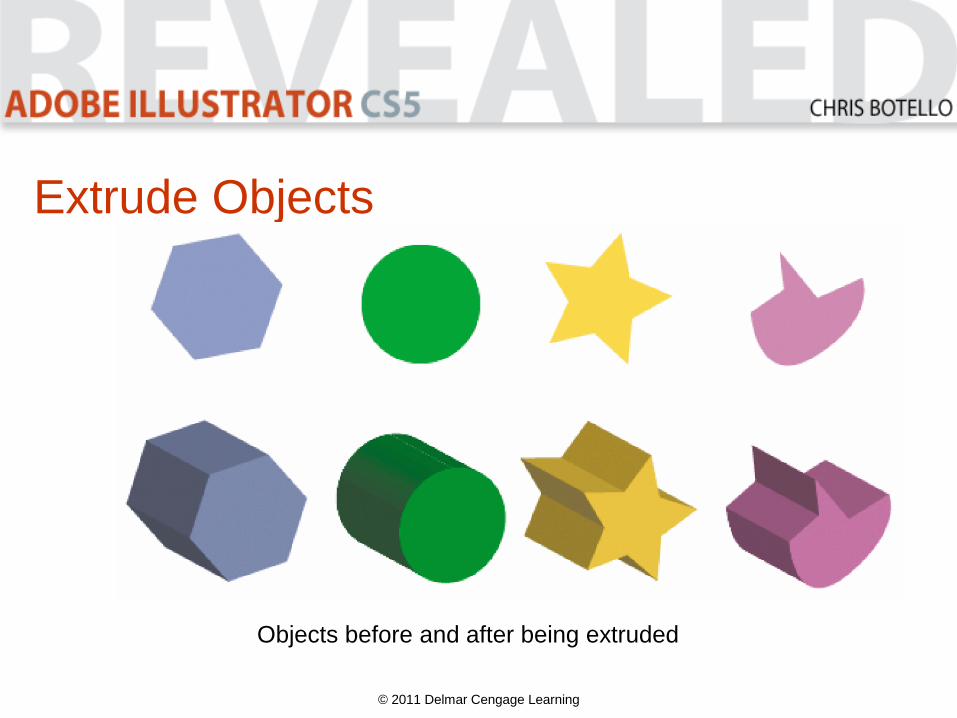
Extrude Objects
© 2011 Delmar Cengage Learning
Objects before and after being extruded
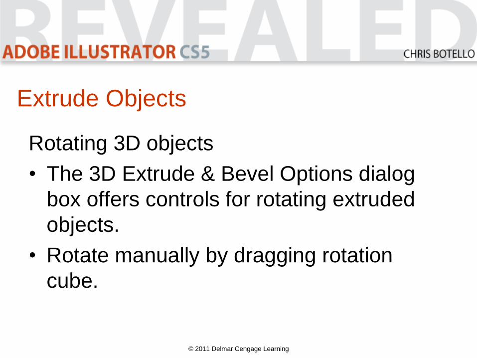
Extrude Objects
Rotating 3D objects
• The 3D Extrude & Bevel Options dialog
box offers controls for rotating extruded
objects.
• Rotate manually by dragging rotation
cube.
© 2011 Delmar Cengage Learning

Extrude Objects
• When you rotate the cube, values on the
X, Y, and Z axes update to reflect the
changes made.
• Enter values in these boxes to rotate
object at specific angles.
• Once you extrude an object, you can view
any surface – front, back, left, or right.
© 2011 Delmar Cengage Learning
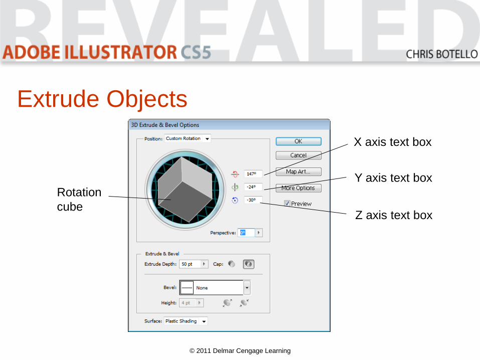
Extrude Objects
© 2011 Delmar Cengage Learning
Rotation
cube
X axis text box
Y axis text box
Z axis text box
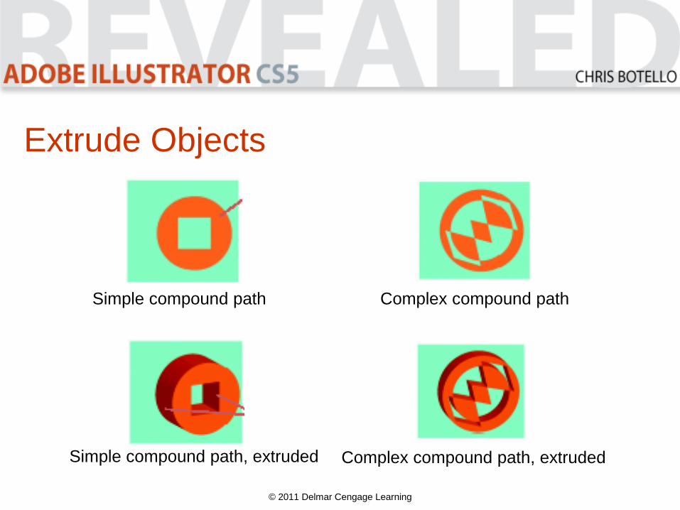
Extrude Objects
© 2011 Delmar Cengage Learning
Simple compound path Complex compound path
Simple compound path, extruded Complex compound path, extruded
Extrude Objects
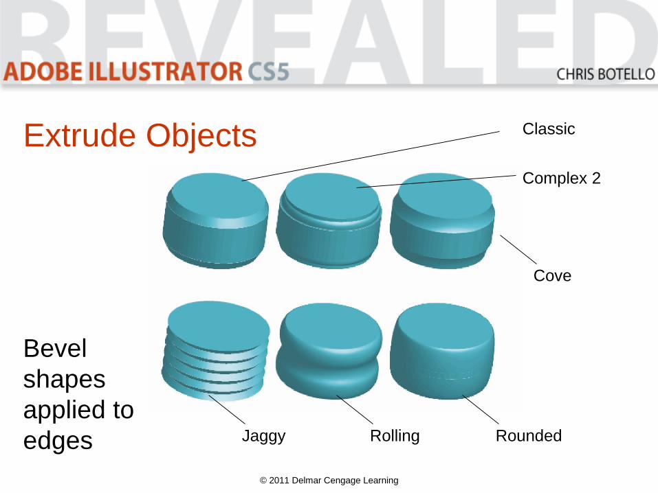
• The Bevel menu offers ten predefined
bevel shapes you can apply to the edge of
an extruded object.
• You control the width of a bevel edge with
the Height slider.
© 2011 Delmar Cengage Learning

Extrude Objects
© 2011 Delmar Cengage Learning
Choose from 1 of
10 bevel shapes
Extrude Objects
© 2011 Delmar Cengage Learning
Cove
RollingJaggy
Classic
Complex 2
Rounded
Bevel
shapes
applied to
edges
Extrude Objects
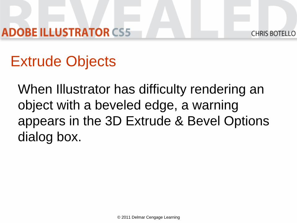
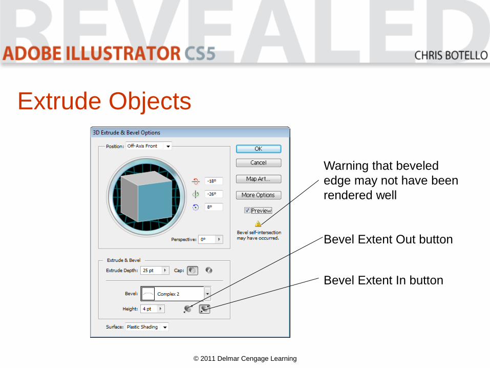
When Illustrator has difficulty rendering an
object with a beveled edge, a warning
appears in the 3D Extrude & Bevel Options
dialog box.
© 2011 Delmar Cengage Learning

Extrude Objects
• Sometimes there is no solution, but your
best bet is to reduce the bevel width.
• Decide how to apply bevel using the Bevel
Extent In and Bevel Extent Out buttons in
3D Extrude & Bevel Options dialog box.
© 2011 Delmar Cengage Learning
Extrude Objects
© 2011 Delmar Cengage Learning
Bevel Extent Out button
Bevel Extent In button
Warning that beveled
edge may not have been
rendered well
Extrude Objects
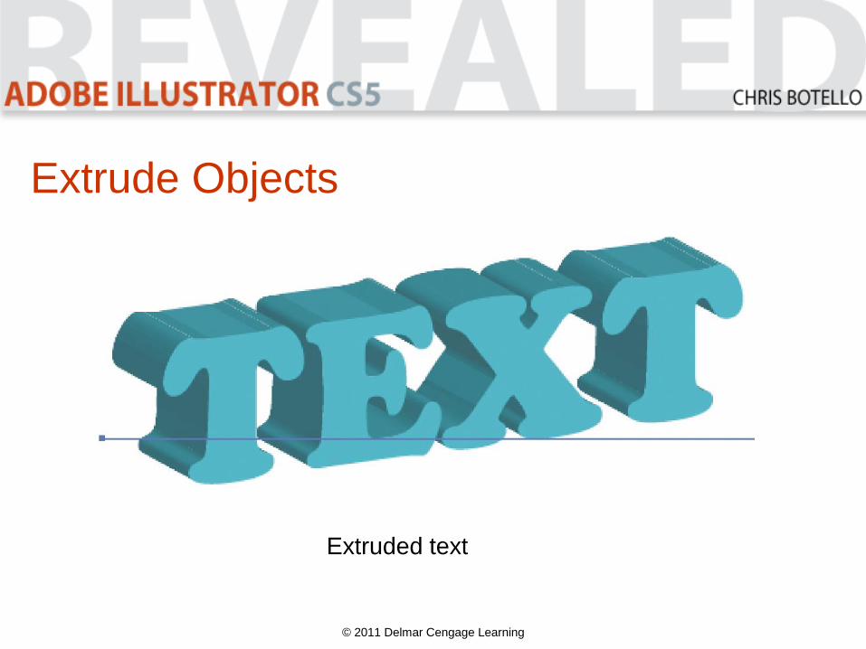
© 2011 Delmar Cengage Learning
Extruded text
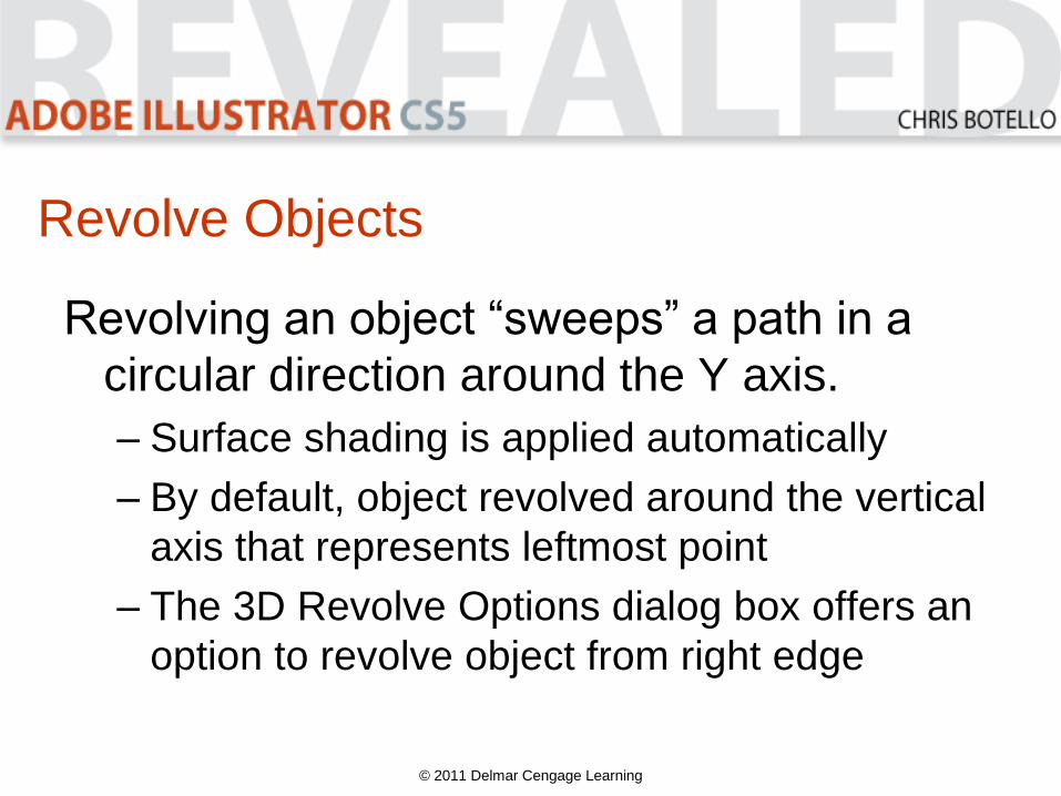
Revolve Objects
Revolving an object “sweeps” a path in a
circular direction around the Y axis.
– Surface shading is applied automatically
– By default, object revolved around the vertical
axis that represents leftmost point
– The 3D Revolve Options dialog box offers an
option to revolve object from right edge
© 2011 Delmar Cengage Learning
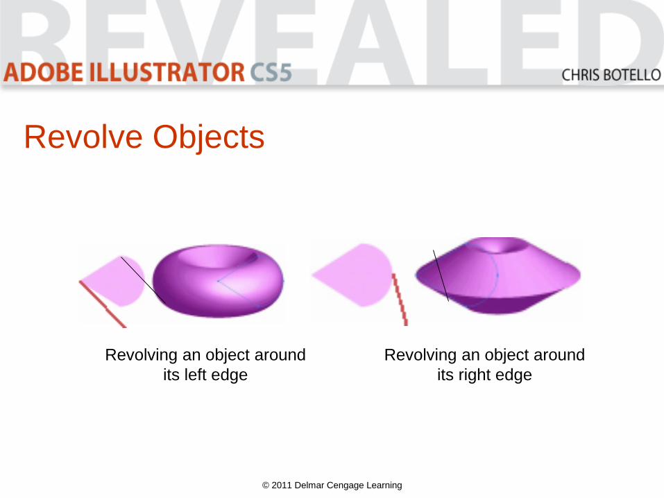
Revolve Objects
© 2011 Delmar Cengage Learning
Revolving an object around
its left edge
Revolving an object around
its right edge
Revolve Objects
• A revolution occurs around the vertical axis.
– Starting path will depict half of the object you
want to revolve
• Once revolved, an object can be rotated by
using the 3D Revolve Options dialog box.
– It presents all surfaces of the graphic
© 2011 Delmar Cengage Learning

Revolve Objects
© 2011 Delmar Cengage Learning
Options for
revolving
objects
Revolve Objects
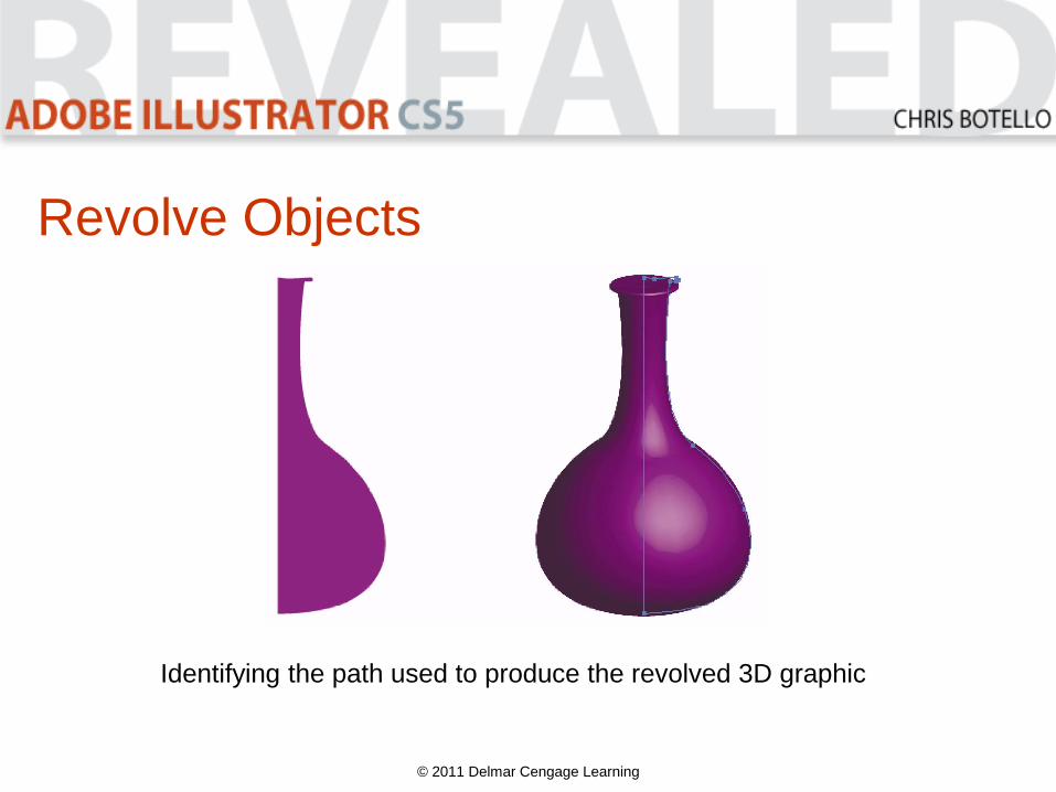
© 2011 Delmar Cengage Learning
Identifying the path used to produce the revolved 3D graphic
Revolve Objects
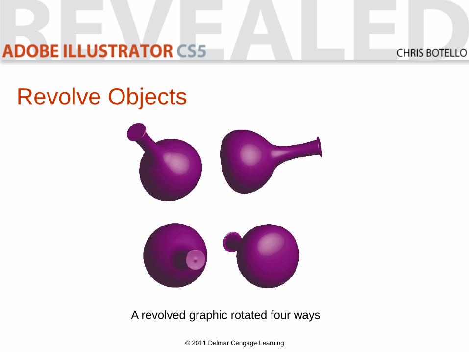
© 2011 Delmar Cengage Learning
A revolved graphic rotated four ways
Revolve Objects
• Apply the Revolve effect to multiple paths
simultaneously.
– Can be open or closed paths
• When Revolve effect is applied to multiple
paths, each path is revolved around its
own axis.
© 2011 Delmar Cengage Learning
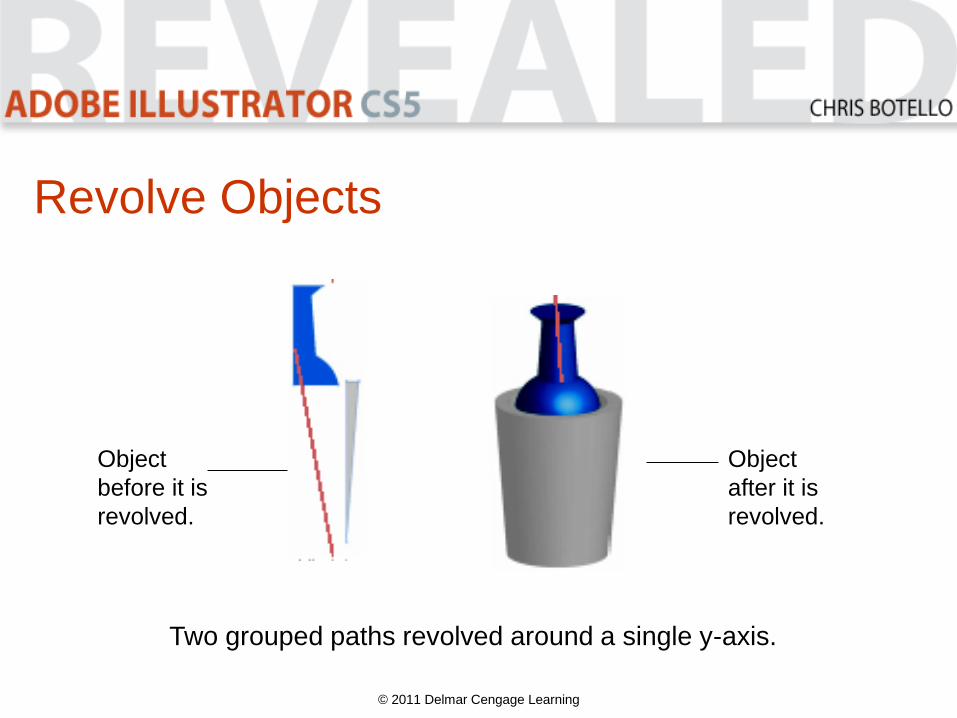
Revolve Objects
Revolving grouped objects
• When grouped, multiple paths are
revolved around a single axis.
• When multiple paths are grouped and
revolved, they will also rotate together.
© 2011 Delmar Cengage Learning
Revolve Objects
© 2011 Delmar Cengage Learning
Two grouped paths revolved around a single y-axis.
Object
before it is
revolved.
Object
after it is
revolved.
Revolve Objects
© 2011 Delmar Cengage Learning
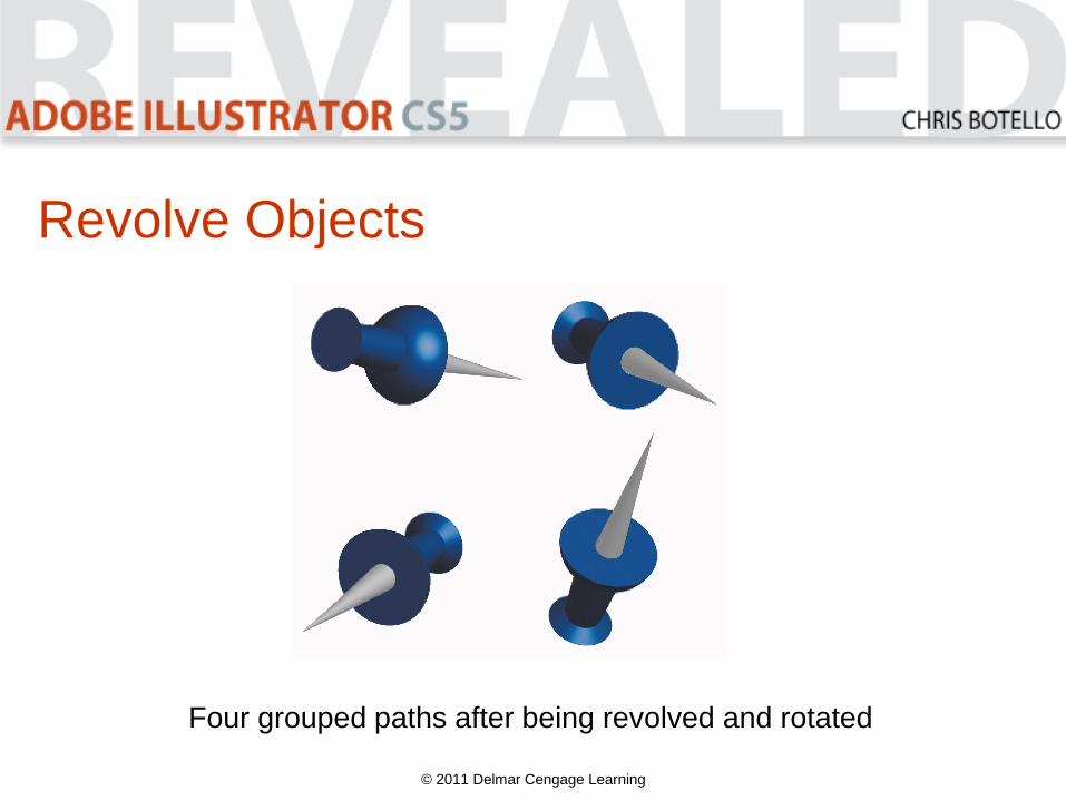
Four grouped paths after being revolved and rotated
Revolve Objects
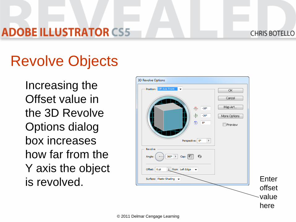
Increasing the
Offset value in
the 3D Revolve
Options dialog
box increases
how far from the
Y axis the object
is revolved.
© 2011 Delmar Cengage Learning
Enter
offset
value
here
Revolve Objects
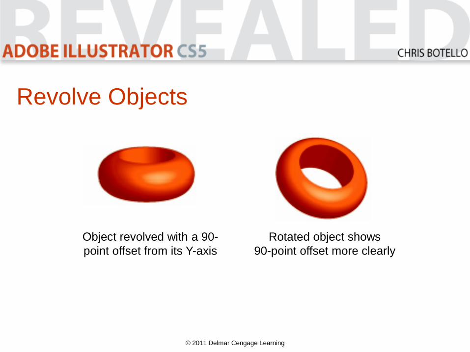
© 2011 Delmar Cengage Learning
Object revolved with a 90-
point offset from its Y-axis
Rotated object shows
90-point offset more clearly
Manipulate Surface Shading and Lighting
When you apply the Extrude & Bevel effect
or Revolve effect, surface shading and
lighting is applied automatically but can be
manipulated.
© 2011 Delmar Cengage Learning

Manipulate Surface Shading and Lighting
• When you revolve an object, four surface
shadings are available:
– Wireframe
– No Shading
– Diffuse Shading
– Plastic Shading
© 2011 Delmar Cengage Learning
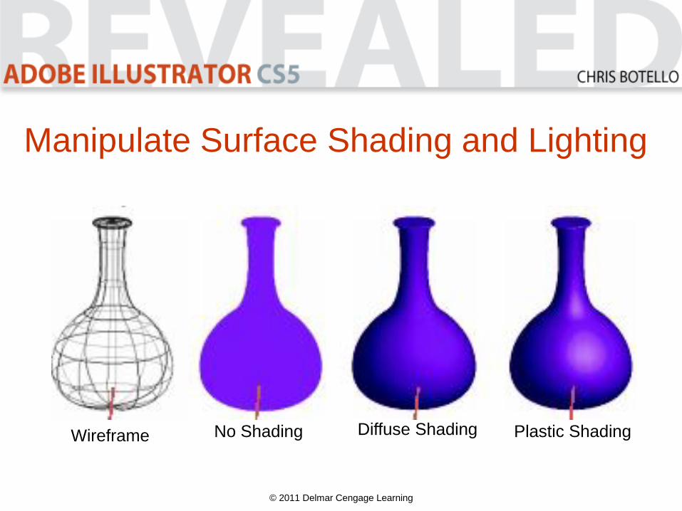
Manipulate Surface Shading and Lighting
© 2011 Delmar Cengage Learning
Wireframe No Shading Diffuse Shading Plastic Shading
Manipulate Surface Shading and Lighting
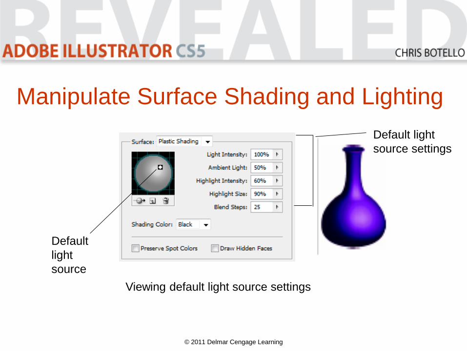
When you choose Diffuse Shading or Plastic
Shading, a number of lighting controls are available.
• Lighting Intensity controls strength of light on object.
• Ambient Light determines how object is lit globally.
• Highlight Intensity controls how intense highlight appears.
• Highlight Size controls how large highlights appear.
• Blend Steps controls how smoothly shading appears.
© 2011 Delmar Cengage Learning
Manipulate Surface Shading and Lighting
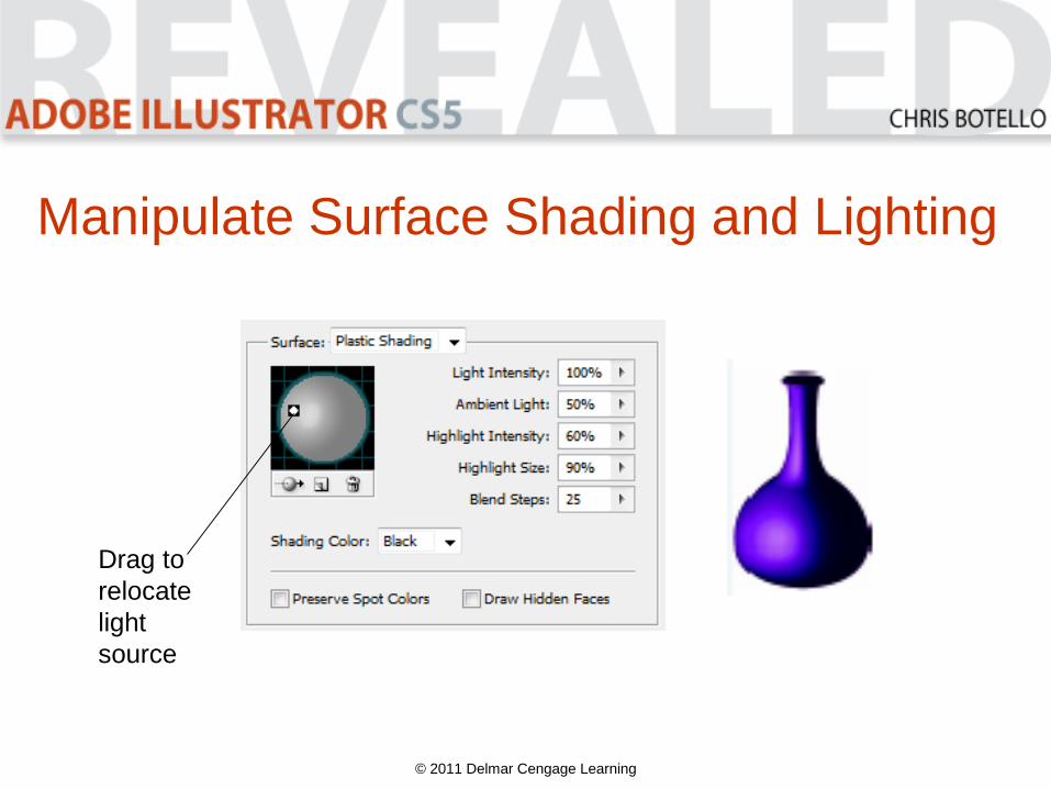
When Diffuse Shading or Plastic Shading is
chosen, you can drag light source to a new
location to light an object from a different
angle.
© 2011 Delmar Cengage Learning
Manipulate Surface Shading and Lighting
• Add additional light sources by clicking New
Light button.
• Apply different light intensity values to individual
light sources.
• Delete a light source by selecting it, then clicking
Delete Light button.
• Move selected light to back button moves
light source to back.
© 2011 Delmar Cengage Learning
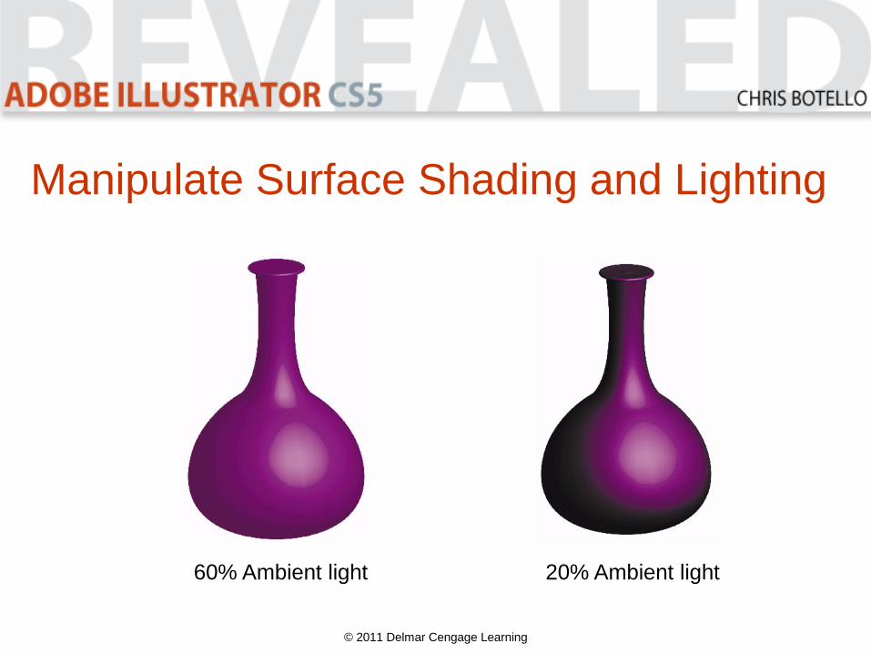
Manipulate Surface Shading and Lighting
© 2011 Delmar Cengage Learning
20% Ambient light60% Ambient light
Manipulate Surface Shading and Lighting
© 2011 Delmar Cengage Learning
Default
light
source
Viewing default light source settings
Default light
source settings
Manipulate Surface Shading and Lighting
© 2011 Delmar Cengage Learning
Drag to
relocate
light
source
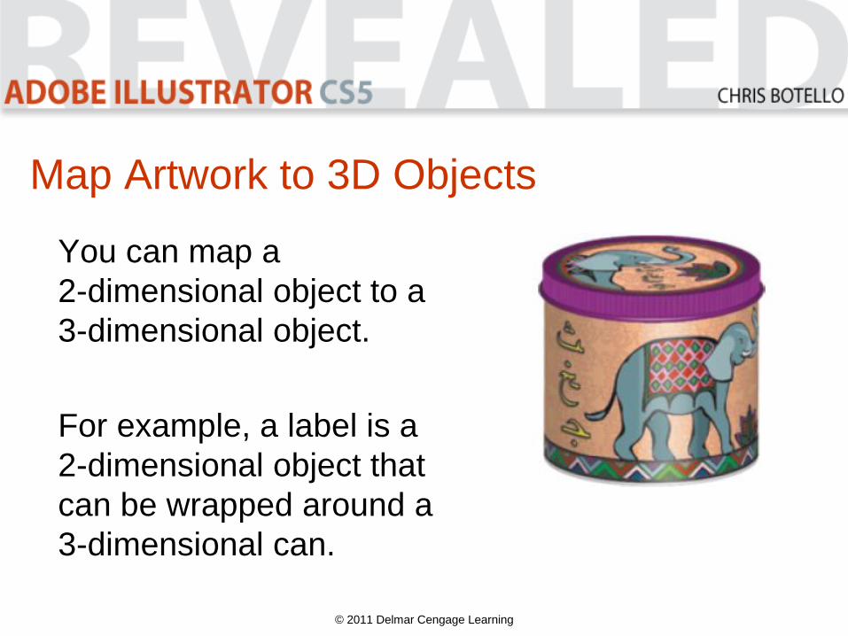
Map Artwork to 3D Objects
You can map a
2-dimensional object to a
3-dimensional object.
For example, a label is a
2-dimensional object that
can be wrapped around a
3-dimensional can.
© 2011 Delmar Cengage Learning
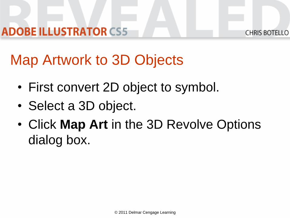
Map Artwork to 3D Objects
• First convert 2D object to symbol.
• Select a 3D object.
• Click Map Art in the 3D Revolve Options
dialog box.
© 2011 Delmar Cengage Learning
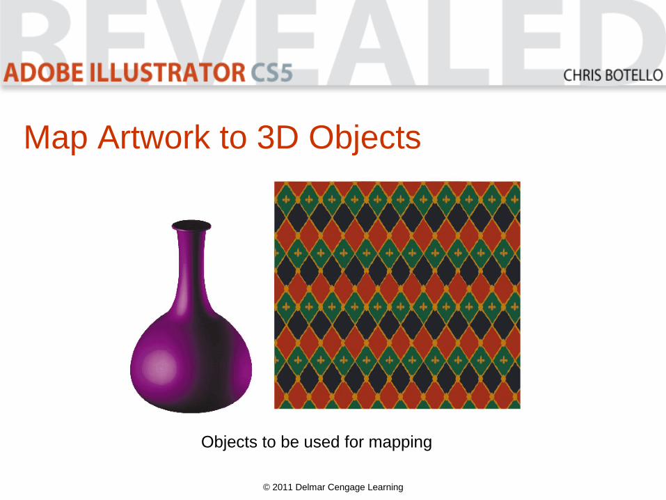
Map Artwork to 3D Objects
© 2011 Delmar Cengage Learning
Objects to be used for mapping
Map Artwork to 3D Objects
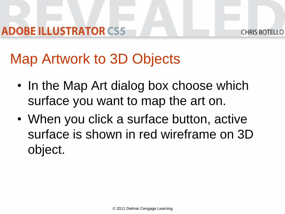
• In the Map Art dialog box choose which
surface you want to map the art on.
• When you click a surface button, active
surface is shown in red wireframe on 3D
object.
© 2011 Delmar Cengage Learning
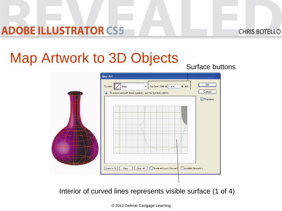
Map Artwork to 3D Objects
© 2011 Delmar Cengage Learning
Surface buttons
Interior of curved lines represents visible surface (1 of 4)
Map Artwork to 3D Objects
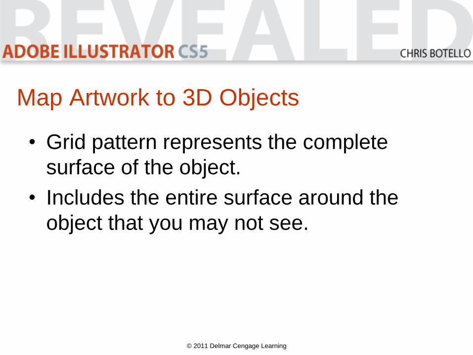
• Grid pattern represents the complete
surface of the object.
• Includes the entire surface around the
object that you may not see.
© 2011 Delmar Cengage Learning
Map Artwork to 3D Objects
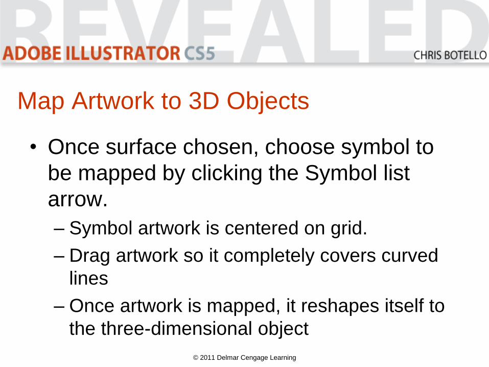
• Once surface chosen, choose symbol to
be mapped by clicking the Symbol list
arrow.
– Symbol artwork is centered on grid.
– Drag artwork so it completely covers curved
lines
– Once artwork is mapped, it reshapes itself to
the three-dimensional object
© 2011 Delmar Cengage Learning
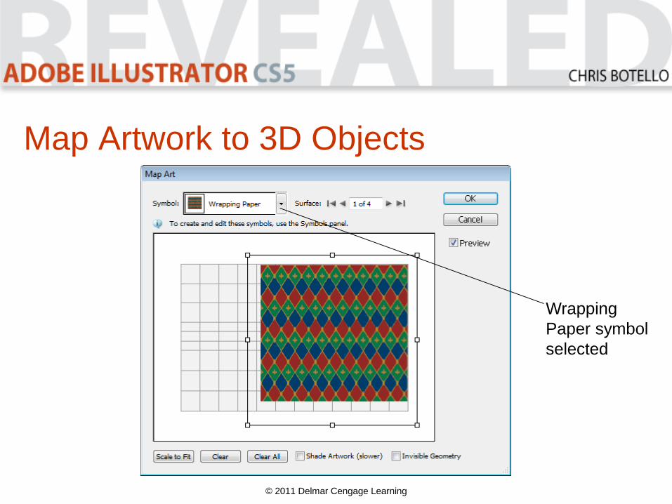
Map Artwork to 3D Objects
© 2011 Delmar Cengage Learning
Wrapping
Paper symbol
selected
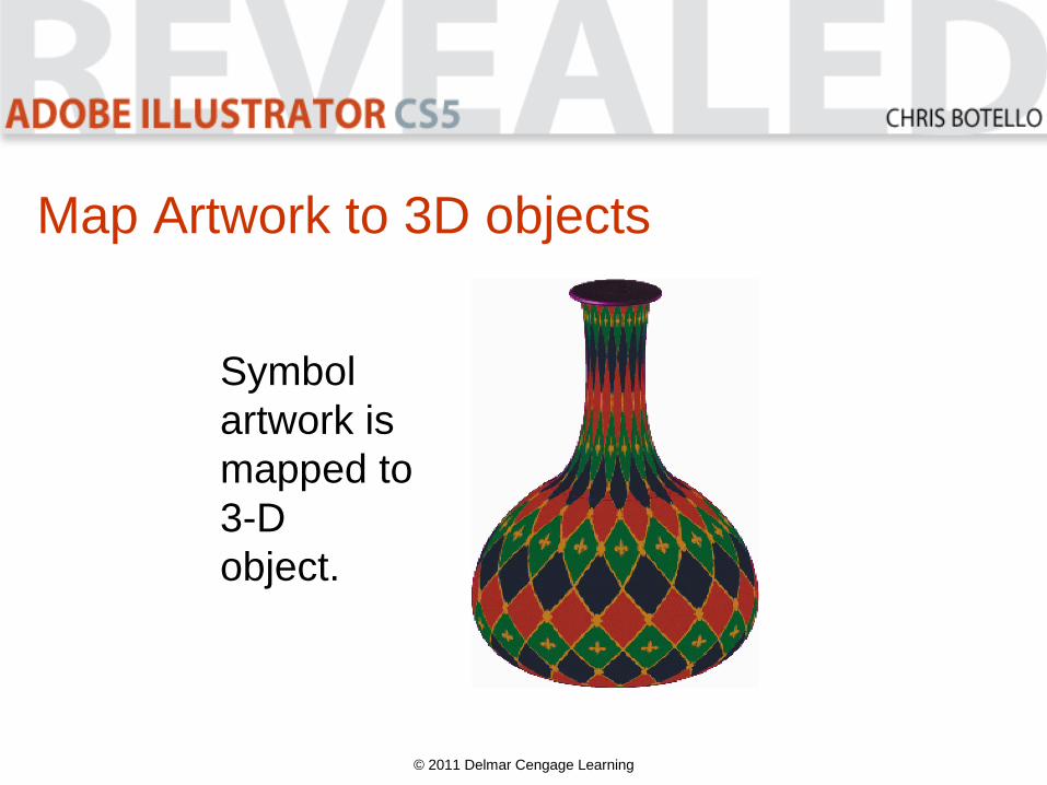
Map Artwork to 3D objects
© 2011 Delmar Cengage Learning
Symbol
artwork is
mapped to
3-D
object.
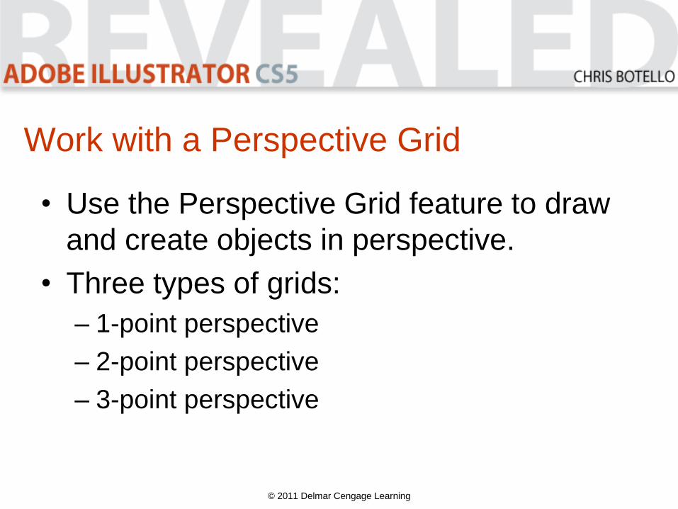
Work with a Perspective Grid
• Use the Perspective Grid feature to draw
and create objects in perspective.
• Three types of grids:
– 1-point perspective
– 2-point perspective
– 3-point perspective
© 2011 Delmar Cengage Learning
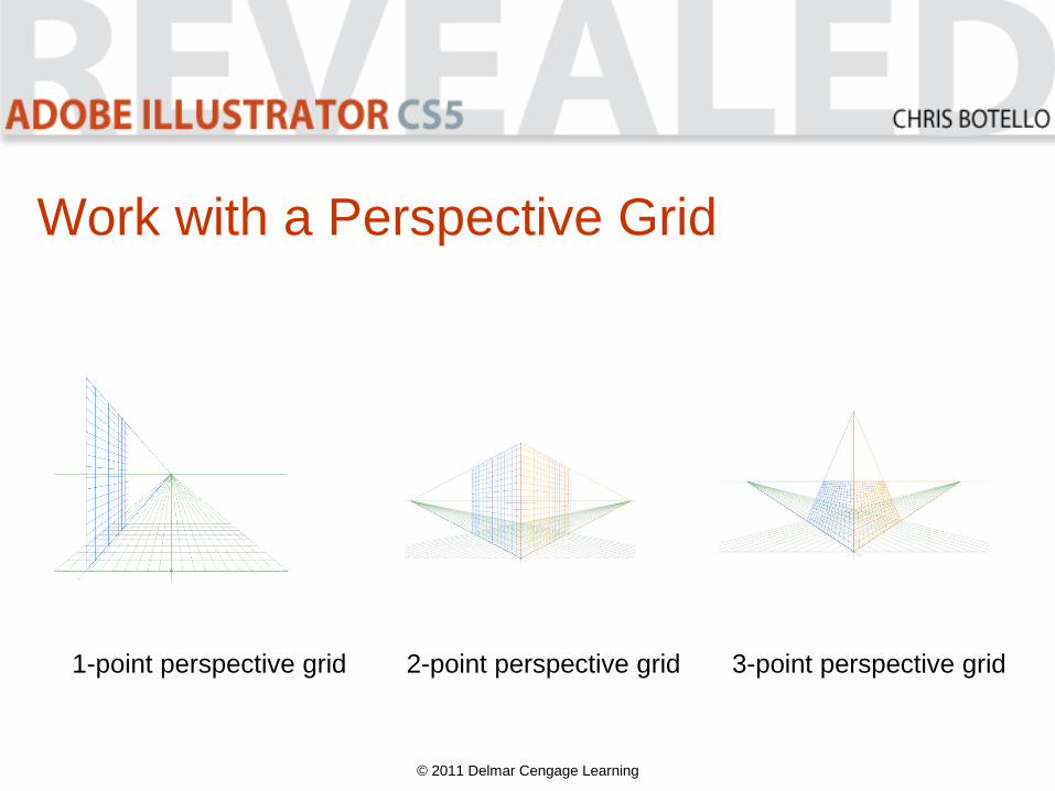
Work with a Perspective Grid
© 2011 Delmar Cengage Learning
1-point perspective grid 2-point perspective grid 3-point perspective grid
Work with a Perspective Grid
• Point refers to vanishing point.
• 2-point perspective is the default.
• Click the Perspective Grid tool on the
Tools panel to access the grid.
• Or select to show it on the View menu.
• You can resize and reshape the grid.
© 2011 Delmar Cengage Learning
• Save your modified grid as a Perspective
Grid Preset.
• You can modify your saved preset.
• When you are in Perspective Grid mode,
the basic shape tools draw in perspective.
© 2011 Delmar Cengage Learning
Work with a Perspective Grid
Work with a Perspective Grid
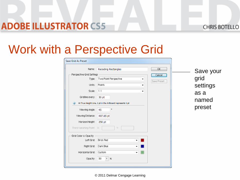
© 2011 Delmar Cengage Learning
Save your
grid
settings
as a
named
preset
Work with a Perspective Grid
© 2011 Delmar Cengage Learning
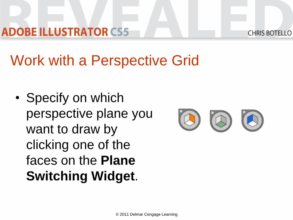
• Specify on which
perspective plane you
want to draw by
clicking one of the
faces on the Plane
Switching Widget.
Work with a Perspective Grid
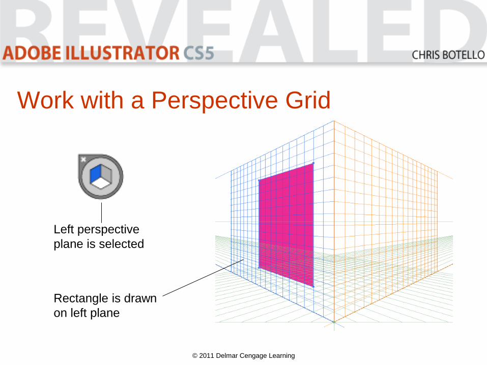
© 2011 Delmar Cengage Learning
Left perspective
plane is selected
Rectangle is drawn
on left plane
Work with a Perspective Grid
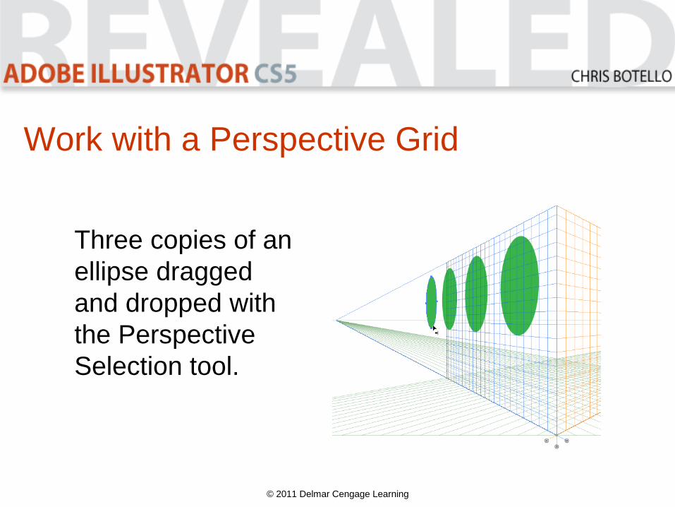
Once you’ve drawn objects in perspective,
use the Perspective Selection tool to click
and drag objects to move and modify them
in perspective.
© 2011 Delmar Cengage Learning
Work with a Perspective Grid
© 2011 Delmar Cengage Learning
Three copies of an
ellipse dragged
and dropped with
the Perspective
Selection tool.
Top Related