


Languages
Pages
Legal


Chalmers University of Technology
Lecture 5
• Shaft power cycles– Cycle selection– Technology trends
• Aircraft engine performance– Thrust and propulsion efficiency– Intakes and engine installation
• Theory 5.1 and 5.2
• Problem 3.1

Chalmers University of Technology
Simple ideal cycle – max. efficiency• Maximum thermal efficiency
when compressor exit temp. = max allowed turbine inlet temp.
– T3 = 1500 => η = 81% efficiency attained at rc = 320
• In practice titanium alloy compressor rotors withstand around 870 K and nickel alloys around 990 K– T3 = 990 K => η = 71% efficiency
attained at rc = 75
T2 => Tmax

Chalmers University of Technology
Simple real cycle – max. efficiency• Setting:
– T3 = 1500 => η∞,c = 87%, η∞,t = 85%, 5% burner pressure drop and 99% mechanical efficiency => no power delivered at rc = 143 (far above allowable t2).
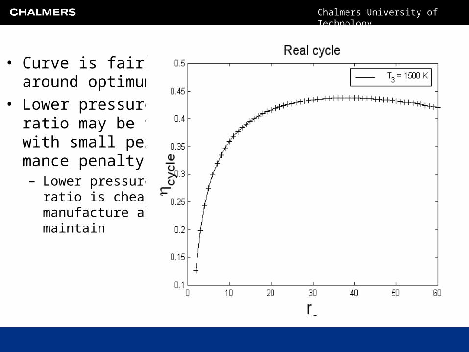
• For real cycle maximum efficiency obtained for (with data above)– rc = 38 at which a cycle efficiency of
η = 43.8% is obtained.
Conservative assumptions (old technology)
Chalmers University of Technology
• Curve is fairly flat around optimum
• Lower pressure ratio may be taken with small perfor-mance penalty– Lower pressure
ratio is cheaper to manufacture and maintain

Chalmers University of Technology
• Suitable compromise in this case is:– rc = 20
• Selecting a lower rc also– Reduces the number of
required turbomachinerystages
– Allows more efficientcooling (Tc low)
Between 0.6-0.7 is current
state of the art.
coolantgasgasmetal
coolantgas
metalgas
TTTT
TT
TT

Chalmers University of Technology
GTX 100
π = 19.2T3 = 1570 K
Chalmers University of Technology
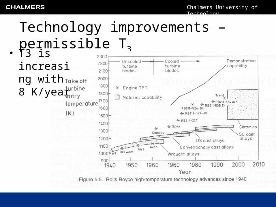
Technology improvements – permissible T3
• T3 is increasing with 8 K/year

Chalmers University of Technology
Technology improvements – permissible T3

Chalmers University of Technology
Cycle Efficiency• Optimal pressure ratio
increase with t3.
• Gain in efficiency becomes marginal as T3 increases

Chalmers University of Technology
Specific output• Considerable increase
in specific outputwith increasing t3.
• Trend:– Increase T3 to increase
specific output
– Follow with rc to obtain high efficiency

Chalmers University of Technology
Heat exchange cycle
)1(21
tr
• Recall:– Heat exchanger
useful when:
– Optimum for r > 1in real cycle.
– Optimum rc increasewith t3.
– Gain in efficiency with t3 is greater than for simple cycle
– Power output curves about the same
– Cooling simplified – t2 low

Chalmers University of Technology
131
• Heat exchanger cycle:– IRA (intercooled recuperated
promises increased fuelefficiency).
– More efficient cooling– Heavy and bulky
Heat exchanger versus simple cycle

Chalmers University of Technology
Which cycle has the highest ideal efficiency?
3
1
1
3
1
3
1
,
3
1
1
3
1
2,
11
111
11
11
1
T
T
TT
r
TTr
T
T
TT
TT
cc
exchangerheatth
simpleth
Theoretically the same!

Chalmers University of Technology
What are the fundamentals of flight?
• The performance of the jet engine
• Aircraft aerodynamics– Covered by the Henrik Ekstrand
material
• Characteristics of the atmosphere

Chalmers University of Technology
drag momentum intake thrustmomentum gross
aj mCmC
ThrustNet
momentumofchangeofRate
Aircraft propulsion – thrust generation

Chalmers University of Technology
thrustpressure
ajjaj ppACCm
ThrustNet
Jet engine – principles of thrust generation

Chalmers University of Technology
Efficiency considerationsHow much of the power in the jet is transformed to thrust ?:
22
22
aj mCmCKEenergykineticinChange
ajaa CCmCFCaircrafttoPower
22
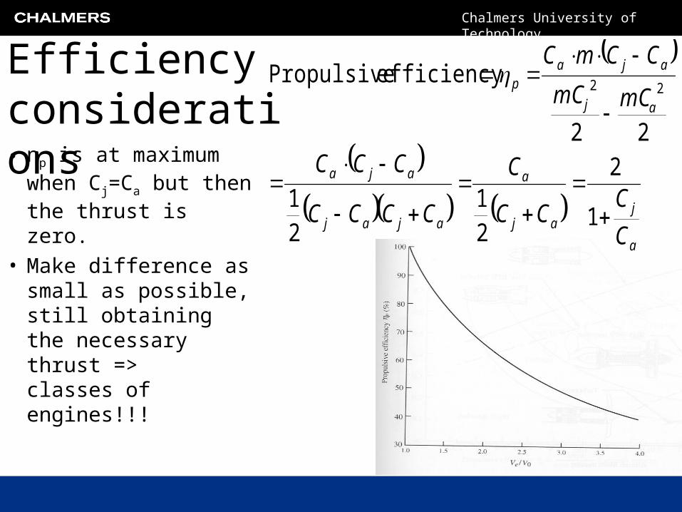
efficiency Propulsive22
aj
aja
mCmC
CCmC
Chalmers University of Technology
Efficiency considerations• ηp is at maximum
when Cj=Ca but then the thrust is zero.
• Make difference as small as possible, still obtaining the necessary thrust =>classes of engines!!!
a
jaj
a
ajaj
aja
aj
ajap
C
CCC
C
CCCC
CCC
mCmC
CCmC
1
2
21
21
22
efficiency Propulsive22

Chalmers University of Technology
Further efficiency considerations
pnetf
aj
e Qm
mCmC
conversionenergyofEfficiency,
22
2
pnet
a
pnetf
a
QSFC
C
Qm
CFefficiencyOverall
,,o
1
2
2
,,
22
22 opnetf
a
pnetf
aj
aj
aep Qm
FC
Qm
mCmC
mCmC
FC
Note that:

Chalmers University of Technology
How should we design the engine
• Decrease T3 => Decrease jet velocity
– Poor cycle efficiency – Poor specific output => high engine weight
• What if we could:– Use high T3 and rc cycle and still obtain an average
low Cj, optimized for the aircraft speed Ca !?

Chalmers University of Technology
Propulsion engines – families
The turbofan:BPR 0+-10
h
c
m
m bpr

Chalmers University of Technology
The turboprop: BPR typically around 25-30
Propulsion engines – families
Chalmers University of Technology
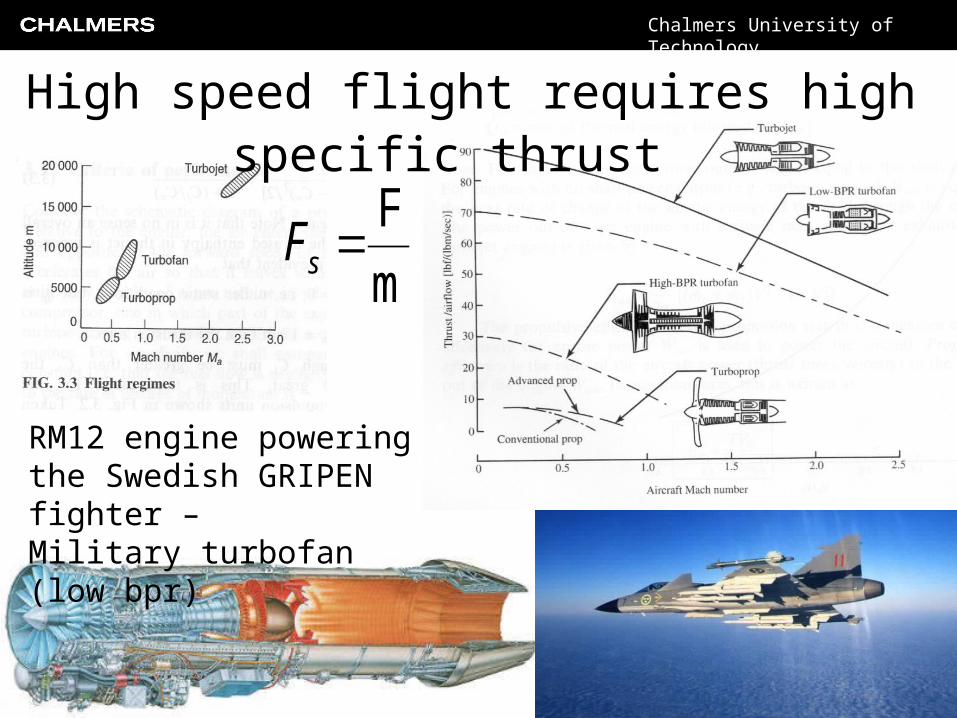
RM12 engine powering the Swedish GRIPEN fighter – Military turbofan (low bpr)
m
F sF
High speed flight requires high specific thrust

Chalmers University of Technology
Variable intake optimize aerodynamicperformance of “shock-compression”system
Very high speed flight requires very high specific thrust
Chalmers University of Technology
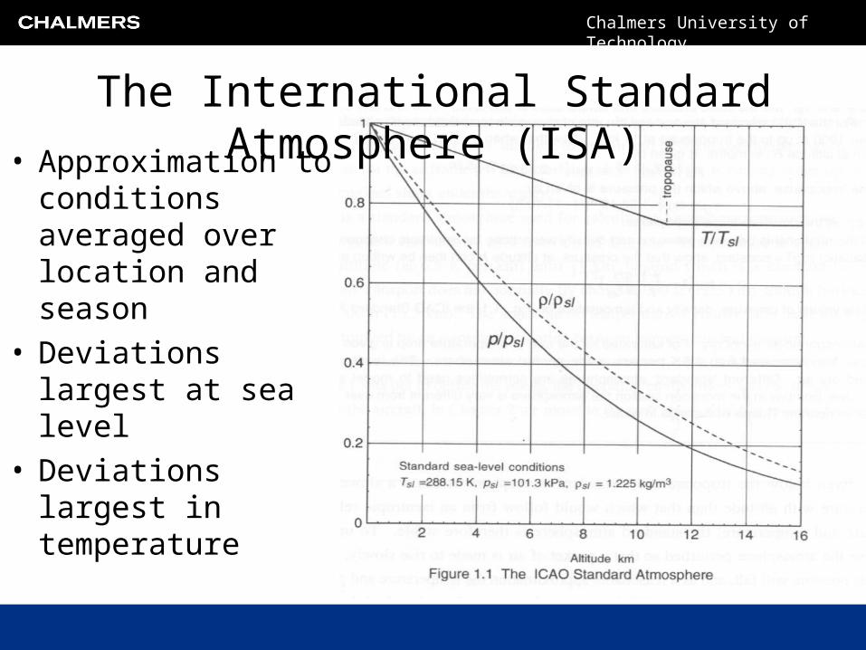
• Approximation to conditions averaged over location and season
• Deviations largest at sea level
• Deviations largest in temperature
The International Standard Atmosphere (ISA)

Chalmers University of Technology
The International Standard Atmosphere (ISA)
• Temperature drops with 6.5K per 1000 meters
• At 11000 m variation stops and T remains constant up to 20000 meters
• Pressure variation can be computed by simple integration of hydrostatic effects.
gdhRT
PlawgasIdealgdhdP
hTT SL3105.6
h
SL
P
P hTR
gdh
P
dP
SL 03105.6

Chalmers University of Technology
Hydrostatic integration....
R
g
SL
SL
SL
SL
h
SLPP
T
hT
T
hT
R
g
hTR
gP
SL
3105.63
SL
3
3SL
0 3
3
105.6PP
105.6
ln105.6P
Pln
105.6ln105.6
ln

Chalmers University of Technology
Intakes• Adiabatic duct used to recover kinetic energy in air
at minimal pressure loss, i.e. we have
0
2200
01020102
21
1
22
2
0102
TTchh
Vh
Vhwq
p
hh
Another example of th
e
first la
w for o
pen systems
with no heat o
r work
exchange (same id
ea
as for th
e nozzle)

Chalmers University of Technology
Intake efficiencies• The available stagnation temperature is:
a
ai TT
TT
01
01
201
1201
2
11
2
11
aa
aia
MT
T
MP
P
p
aa c
CTT
2
2
01
T´01is the stagnation temperature that would have been necessary to achieve P01 under isentropic conditions, i.e.:
Some algebra gives (as well as definition of Mach number and a relation for cp):

Chalmers University of Technology
Intakes• Design criteria:
– Minimize inlet compressor inlet distortion
– Distortion may lead to surge => flame out or mechanical damages

Chalmers University of Technology
Functionality• Static conditions, very low aircraft speeds
– Intake acts as a nozzle
• Cruise – normal forward speeds– Intake performs as diffuser
• Supersonic operation– System of shock waves
followed by a subsonic diffusion section
Chalmers University of Technology
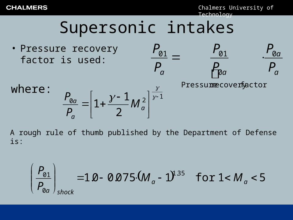
Supersonic intakes• Pressure recovery factor
is used: a
a
aa P
P
P
P
P
P 0
factorrecovery Pressure
0
0101
120
2
11
a
a
a MP
Pwhere:
A rough rule of thumb published by the Department of Defense is:
5 1for 1075.00.1 35.1
0
01
aa
shocka
MMP
P

Chalmers University of Technology
SR71 – intake ram pressure ratio

Chalmers University of Technology
SR71 – intake ram pressure ratioThe ram pressure rise is estimated using the following expression:
a
a
aa P
P
P
P
P
P 0
factorrecovery Pressure
0
0101
where the second factor in the left hand expression is obtained from:
120
2
11
a
a
a MP
P
shockasubsonicaa P
P
P
P
P
P
0
01
0
01
0
01the first factor is obtained from:
Includes both shock and viscous losses

Chalmers University of Technology
SR71 – intake ram pressure ratio
960.0]part) subson.(for - 1[
21
1
21
1
12
12
0
01
a
a
ai
subsonica
M
M
M
P
P
The subsonic part is calculated from from our “universal” assumption of ηi=0.93, i.e:
The shock pressure recovery factor is estimated by the crude formula stated by the Department of Defence (assuming a cruise Mach number of 3.0):
0.809 1075.00.1 35.1
0
01
a
shocka
MP
P

Chalmers University of Technology
and thus the pressure recovery factor is: 0.776 809.0960.00
01 aP
P
SR71 – intake ram pressure ratio
The pressure ratio over the intake can finally be estimated to:
!!! 5.287.36776.00
factorrecovery Pressure
0
0101 a
a
aa P
P
P
P
P
P
This is a very crude approximation methodology, but it gives a demonstration of the considerable pressure ratio that a successfully designed inlet may give. It also illustrates why the ram jet engine provides a thermodynamically attractive cycle at very high speeds.

Chalmers University of Technology
Some examples of engine installation

Chalmers University of Technology
Engine installation examples
• Wing mounted pod installation (attached to the wing by pylons):
• Third engine buried in the tail fuselage

Chalmers University of Technology
Theory 5.1 – Stagnation pressure for isentropic compression
We have already introduced the stagnation temperature as:
pc
VTT
2
2
0
and shown that (revision task): Rcc vp
The Mach number is defined as:
RT
V
soundofspeed
V
a
VM
*
The specific heat ratio γ is defined:
v
p
c
c

Chalmers University of Technology
Thus:
120
2
11
M
P
P
2
11
2
1
2
1
12
202
22
0
MT
TTMT
TMT
R
c
c
RTMTT p
p
100
T
T
P
Pbut we have: which directly gives:
Theory 5.1 – Stagnation pressure for isentropic compression

Chalmers University of Technology
Theory 5.2 - Continuity in stagnation property form
)1(2
)1(
2
0
02
1
12
0
0
2
0
120
/1
2
11
2
11
21
1
21
1
]properties stagnation use[
][
MRT
APMM
RT
APM
A
M
TR
MPMA
RT
PM
ART
PMRTAM
RT
P
RTMVAVRT
PRTvPAVm

Chalmers University of Technology
),(2
11
)1(2
)1(
2
0
0 MMMAP
RTm
Thus:
extremely powerful.
Theory 5.2 - Continuity in stagnation property form

Chalmers University of Technology
Learning goals
• Have an understanding for the propulsive efficiency concept and how it:– relates to the total efficiency– relates to the different jet engine types available
• Have a quantitative understanding of how real cycle effects impact cycle efficiency and choice of design conditions
• Have a basic understanding of how intakes work and know how engines can be integrated in aircraft
Top Related