


Languages
Pages
Legal


© CFturbo Software & Engineering GmbH
CFturbo 9.2
User manual for CFturbo 9.2 software

CFturbo 9.2Introduction
This manual describes the usage of the software CFturbo 9.2and corresponds to the online help with regards to content.
All rights reserved. No parts of this work may be reproduced in any form or by any means - graphic, electronic, ormechanical, including photocopying, recording, taping, or information storage and retrieval systems - without thewritten permission of the publisher.
Products that are referred to in this document may be either trademarks and/or registered trademarks of therespective owners. The publisher and the author make no claim to these trademarks.
While every precaution has been taken in the preparation of this document, the publisher and the author assume noresponsibility for errors or omissions, or for damages resulting from the use of information contained in thisdocument or from the use of programs and source code that may accompany it. In no event shall the publisher andthe author be liable for any loss of profit or any other commercial damage caused or alleged to have been causeddirectly or indirectly by this document.
© CFturbo Software & Engineering GmbH, 2014

3Contents
© CFturbo Software & Engineering GmbH
Table of Contents
Part I CFturbo 9 8
Part II General 11
................................................................................................................................... 111 Licensing
........................................................................................................................... 14Local license setup
........................................................................................................................... 16Network license setup .................................................................................................................... 17License server setup.................................................................................................................... 21Client setup
........................................................................................................................... 22Show license information
........................................................................................................................... 23Troubleshooting ................................................................................................................................... 252 Batch mode
........................................................................................................................... 27Parameters for impellers
........................................................................................................................... 31Parameters for volutes
........................................................................................................................... 31Exit Codes
........................................................................................................................... 32Example ................................................................................................................................... 353 Project structure and interfaces
........................................................................................................................... 37Interface definition ................................................................................................................................... 394 Graphical dialogs
................................................................................................................................... 415 Edit fields with empirical functions
Part III Start 43
Part IV Opened project 46
Part V Component design process 49
Part VI Menu 53
................................................................................................................................... 551 File
........................................................................................................................... 55Create new design
........................................................................................................................... 56Open/ Save design ................................................................................................................................... 572 Project
........................................................................................................................... 57Project .................................................................................................................... 58Project information.................................................................................................................... 58Global setup.................................................................................................................... 64Performance prediction.................................................................................................................... 70Export
............................................................................................................. 75Basic
............................................................................................................. 78CAD
............................................................................................................. 81CFD
............................................................................................................. 84Specifics...................................................................................................................................... 85Autodesk AutoCAD
...................................................................................................................................... 91Autodesk Inventor
...................................................................................................................................... 94Catia (Dassault Systèmes)

CFturbo 9.24
© CFturbo Software & Engineering GmbH
...................................................................................................................................... 94Numeca AutoGrid5
...................................................................................................................................... 96Creo Parametric (PTC)
...................................................................................................................................... 112Ansys ICEM CFD
...................................................................................................................................... 114STL
............................................................................................................. 114Data export limitations.................................................................................................................... 115Import 3D geometry.................................................................................................................... 115Reference components.................................................................................................................... 118Show/Hide messages.................................................................................................................... 118Undo
........................................................................................................................... 119Selected component .................................................................................................................... 119Add component.................................................................................................................... 120Active/ Rename/ Delete.................................................................................................................... 122Remove design steps
................................................................................................................................... 1233 Impeller/ Stator/ Volute
................................................................................................................................... 1234 Preferences
........................................................................................................................... 124Licensing
........................................................................................................................... 124Approximation functions
........................................................................................................................... 129Fluids
........................................................................................................................... 132General
........................................................................................................................... 135Units .................................................................................................................... 136General.................................................................................................................... 136Specific speed.................................................................................................................... 138Other
........................................................................................................................... 139Impeller/ Stator ................................................................................................................................... 1405 3D Model
................................................................................................................................... 1416 3D Model - Blades
................................................................................................................................... 1417 Report
................................................................................................................................... 1428 Help
........................................................................................................................... 142Check for Updates
Part VII Views 145
................................................................................................................................... 1461 Meridian
................................................................................................................................... 1502 3D Model
........................................................................................................................... 151Model display (top)
........................................................................................................................... 157Model tree (left)
........................................................................................................................... 161Problems when generating the 3D model ................................................................................................................................... 1643 Report
Part VIII Impeller 166
................................................................................................................................... 1661 Main dimensions
........................................................................................................................... 167Pump / Ventilator .................................................................................................................... 169Setup.................................................................................................................... 170Parameters.................................................................................................................... 177Dimensions
........................................................................................................................... 182Compressor .................................................................................................................... 184Setup.................................................................................................................... 185Parameters.................................................................................................................... 191Dimensions
........................................................................................................................... 196Turbine .................................................................................................................... 198Setup

5Contents
© CFturbo Software & Engineering GmbH
.................................................................................................................... 199Parameters
.................................................................................................................... 203Dimensions
........................................................................................................................... 209Shaft/Hub ................................................................................................................................... 2102 Meridional contour
........................................................................................................................... 216Hub-Shroud contour .................................................................................................................... 218Bezier
............................................................................................................. 221Converting Polyline / Bezier.................................................................................................................... 222Circular Arc + Straight line.................................................................................................................... 225Contour
........................................................................................................................... 226Leading-Trailing edge contour
........................................................................................................................... 228Additional views
........................................................................................................................... 230Meridional flow calculation ................................................................................................................................... 2343 Blade properties
........................................................................................................................... 235Blade setup .................................................................................................................... 241Radial element blade
........................................................................................................................... 242Blade angles .................................................................................................................... 245Inlet triangle.................................................................................................................... 248Outlet triangle
............................................................................................................. 250Slip coefficient by AUNGIER
............................................................................................................. 251Slip coefficient by PFLEIDERER
............................................................................................................. 253Slip coefficient by WIESNER
............................................................................................................. 254Slip coefficient by GÜLICH (waste water pumps)................................................................................................................................... 2544 Blade mean lines
........................................................................................................................... 257Freeform blades, 2D blades, Radial element blades
........................................................................................................................... 260Circular blades, Straight blades
........................................................................................................................... 261Additional views .................................................................................................................... 264Sine rule.................................................................................................................... 265Blade lean angle
........................................................................................................................... 267Blade loading calculation ................................................................................................................................... 2705 Blade profiles
........................................................................................................................... 273Converting Polyline / Bezier ................................................................................................................................... 2746 Blade edges
........................................................................................................................... 279Edge position ................................................................................................................................... 2807 CFD Setup
........................................................................................................................... 281Extension
........................................................................................................................... 283Miscellaneous .................................................................................................................... 284Segment.................................................................................................................... 287Blade O-Grid.................................................................................................................... 287Other
................................................................................................................................... 2888 Model settings
................................................................................................................................... 2909 Model finishing
Part IX Stator 296
................................................................................................................................... 2961 Main dimensions
........................................................................................................................... 299Extent
........................................................................................................................... 301Inlet
........................................................................................................................... 302Outlet ................................................................................................................................... 3022 Meridional contour
................................................................................................................................... 3033 Blade properties
........................................................................................................................... 304Number of blades

CFturbo 9.26
© CFturbo Software & Engineering GmbH
................................................................................................................................... 3064 Blade mean lines
................................................................................................................................... 3095 Blade profiles
................................................................................................................................... 3096 Blade edges
................................................................................................................................... 3097 CFD Setup
................................................................................................................................... 3108 Model settings
................................................................................................................................... 3109 Model finishing
Part X Volute 312
................................................................................................................................... 3121 Setup & Inlet
........................................................................................................................... 314Setup
........................................................................................................................... 316Inlet details ................................................................................................................................... 3162 Cross Section
........................................................................................................................... 321Bezier cross section
........................................................................................................................... 322Line Segments cross section
........................................................................................................................... 325Radius based cross section
........................................................................................................................... 326Internal cross sections ................................................................................................................................... 3273 Spiral development areas
........................................................................................................................... 330Design rule
........................................................................................................................... 331Cut-water compensation
........................................................................................................................... 332Additional views ................................................................................................................................... 3334 Diffuser
........................................................................................................................... 339Additional views ................................................................................................................................... 3405 Cut-water
........................................................................................................................... 343Simple
........................................................................................................................... 345Fillet
........................................................................................................................... 348Sharp ................................................................................................................................... 3496 CFD Setup
................................................................................................................................... 3497 Model settings
Part XI Appendix 353
................................................................................................................................... 3531 References
................................................................................................................................... 3562 Symbols
................................................................................................................................... 3573 Contact addresses
................................................................................................................................... 3584 License agreement
Index 367

Part
I

8 CFturbo 9.2
© CFturbo Software & Engineering GmbH
1 CFturbo 9
CFturbo is made to design interactively radial and mixed-flowturbomachinery: pumps, ventilators, compressors, turbines. Thesoftware is easy to use and does enable quick generation andvariation of impeller, stator and volute geometries. Severalmodels can be displayed, compared and modifiedsimultaneously.
It contains numerous approximation functions that may becustomized by the user in order to implement user specificknowledge into the CFturbo-based design process. In spite ofthe creation of semiautomatic proposals, fundamentalexperiences in turbomachinery design are helpful but notnecessary. An experienced turbomachinery design engineershould be able to design new high-quality impellers and volutesmore easily and quickly.
Integration of geometry data into the CAE environment is easily possible by direct interfaces tovarious CAD- and CFD-systems.
Please read the License agreement before using the program.
Information about activating license you can read in chapter Licensing .
358
11

9CFturbo 9
© CFturbo Software & Engineering GmbH
Contact persons you can find under Contact addresses , actual information on the CFturbowebsite.
Copyright © 2014, CFturbo Software & Engineering GmbH
357

Part
II

11General
© CFturbo Software & Engineering GmbH
2 General
This topic contains some general program information about
Licensing
Batch mode
Project structure and interfaces
Graphical dialogs
Edit fields with empirical functions
2.1 Licensing
? Preferences | Licensing
CFturbo can be used without a valid license in viewer mode. This mode allows to open project filesindependent of the included components for reading access. No changes can be done in viewermode.
For modifying projects with CFturbo a valid license is necessary. Does a project include multiplecomponents, only that ones can be modified, a valid license is present for.
For example: A CFturbo project containing a stator, a radial pump impeller and a volute can alwaysbe opened. If only the modules for stator and radial pump impeller have been licensed, only this twocomponents can be modified but not the volute.
A special feature of the CFturbo license model are stators. With every license for volute or radialimpellers it is possible, to create and modify stators without blades.
11
25
35
39
41

12 CFturbo 9.2
© CFturbo Software & Engineering GmbH
w = module data can be modified; r = module data is read only
Menu item Licensing enables license handling.
REQUEST new license by e-mail14
13General
© CFturbo Software & Engineering GmbH
SHOW current license information
License expiration
If the license of a software module has expired, it can be reactivated by replacing the license with anew one.
A hint with remaining days appears on startup screen 20 days before expiration of the license. Thenumber of days for this hint can be specified in Preferences | Settings | General .
Steps for licensing
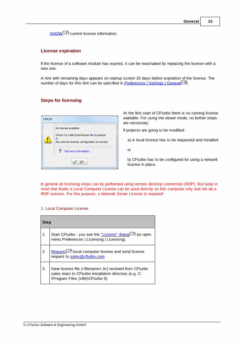
At the first start of CFturbo there is no running licenseavailable. For using the viewer mode, no further stepsare necessary.
If projects are going to be modified:
a) A local license has to be requested and installed
or
b) CFturbo has to be configured for using a networklicense in place.
In general all licensing steps can be performed using remote desktop connection (RDP). But keep inmind that finally a Local Computer License can be used directly on this computer only and not via aRDP session. For this purpose, a Network Server License is required!
1. Local Computer License
Step
1. Start CFturbo - you see the "License" dialog (or openmenu Preferences | Licensing | Licensing).
2. Request local computer license and send licenserequest to [email protected]
3. Save license file (<filename>.lic) received from CFturbosales team to CFturbo installation directory (e.g. C:\Program Files (x86)\CFturbo 9)
22
132
11
14
14 CFturbo 9.2
© CFturbo Software & Engineering GmbH
4. Show license information to check modules and dates
2. Network Server License
(NOT available for trial license)
In advance of using CFturbo with a network license, the license server must be setup (includesrequesting and installing a network license). For details see Network license setup .
Every client computer that should run CFturbo has to be configured for using the network license.
Step
1. Configure computer for network license usage
2. Start CFturbo and open menu Preferences | Licensing |Licensing
3. Show license information to check modules and dates
2.1.1 Local license setup
For using CFturbo with a local license 2 steps have to be performed:
Requesting a license using the CFturbo license dialog
Storing the received license file in the CFturbo installation directory
Note: If CFturbo is configured for using a network license , modules get checked out from thatlicense first if available!
Requesting a local license
If not either a local license file is present or a network license is configured, CFturbo will start thelicensing dialog (Preferences | Licensing | Licensing).
22
16
16
22
16

15General
© CFturbo Software & Engineering GmbH
Here you can select REQUEST new local license by E-mail.
Under Modules the CFturbo modules must get selected for which a license should be requested.

16 CFturbo 9.2
© CFturbo Software & Engineering GmbH
Fill the Company field with the requesting company's name.
The Start date of the requested license can be selected for e.g. sync a short time-period license toa project's start date.
The so-called Machine ID and the Checksum are calculated automatically and ensure the singularusage of provided license information as well as to link the license to the local computer.
After input of all necessary information you can
use the Send E-Mail button to prepare a message with the computer's default mail client(the mail will NOT be sent automatically!)
OR
use the Copy to Clipboard button if you want to create the mail manually and paste theinformation (send the mail to [email protected]).
Install license file
The license file you receive must be stored in the CFturbo installation directory (e.g. C:\ProgramFiles (x86)\CFturbo 9) you have chosen during the setup. It already has .lic as file extension, thisextension must be preserved!
There should be only one license file (*.lic) present in this directory.
Afterwards you can run CFturbo and check the license information .
2.1.2 Network license setup
Selecting the license server machine
Network (floating) licensing requires a CFturbo license server software running on a server machine.The license server controls access of the clients to the CFturbo licenses.
The server machine should have the following properties:
The operating system of the server machine has to be Microsoft Windows®.It's highly recommended to use a server system (Windows Server 20xx).
The server machine has to be located in the same local area network (LAN) of all CFturboclients.Usage of the network licenses in a wide area network (WAN) is not allowed.
The server machine should be highly available, have high-speed Ethernet connection and amoderate level of network traffic.
22
17General
© CFturbo Software & Engineering GmbH
All license related files must be located on a local computer disk of the server machine.
The server machine must have a static IP address.
Make sure that the time and date of the server machine is correct. Do not manipulate thesesettings manually.
License server on Virtual Machines
The CFturbo license server software can be installed and used on a Virtual Machine (e.g. VMware).However, the license handling on a Virtual Machine environment is not tested and certified. Problemsrelated to the use of virtual servers cannot be resolved by the CFturbo support and should bereported to the Virtual Machine supplier.
Note, that using Virtual Machines to duplicate the available CFturbo licenses is explicitly prohibited.
Steps for network licensing
For using CFturbo with a network license the following steps have to be performed:
1. Setting up the CFturbo license server
2. Requesting a license using the Request Generator
3. Storing the received license file in the CFturbo license server installation directory
4. Configuring the clients for accessing the network license
2.1.2.1 License server setup
Installing the license server
The CFturbo license server is installed by a setup separate from the CFturbo program. It includes thefollowing components:
server files
Windows Service "Reprise LM for CFturbo"
Request Generator
this manual
The license server will be installed as a Windows Service which is automatically started on systemboot.
17
19
17
21
18 CFturbo 9.2
© CFturbo Software & Engineering GmbH
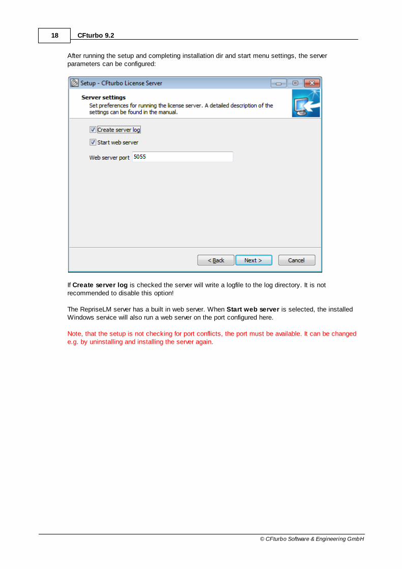
After running the setup and completing installation dir and start menu settings, the serverparameters can be configured:
If Create server log is checked the server will write a logfile to the log directory. It is notrecommended to disable this option!
The RepriseLM server has a built in web server. When Start web server is selected, the installedWindows service will also run a web server on the port configured here.
Note, that the setup is not checking for port conflicts, the port must be available. It can be changede.g. by uninstalling and installing the server again.

19General
© CFturbo Software & Engineering GmbH
The last wizard page offers to Create a license request. This option will start the RequestGenerator.
Requesting a network license
The Request Generator collects all information needed for the license request.

20 CFturbo 9.2
© CFturbo Software & Engineering GmbH
Under Modules the CFturbo modules must get selected for which a license should be requested.Fill the Company field with the requesting company's name.
The Start date of the requested license can be selected for e.g. sync a short time-period license toa project's start date.
The so-called Machine ID and the Checksum are calculated automatically and ensure the singularusage of provided license information as well as to link the license to the network server.
The Concurrent users setting enables you to change to number of users you request the licensefor.
After input of all necessary information you can
- use the Send E-Mail button to prepare a message with the computer's default mail client (themail will NOT be sent automatically!)
OR
- use the Copy to Clipboard button if you want to create the mail manually and paste theinformation (send the mail to [email protected]).

21General
© CFturbo Software & Engineering GmbH
Install license file
The license file you receive must be stored in the license server installation directory (e.g. C:\Program Files (x86)\CFturbo 9\LicenseServer) you have chosen during the setup. It already has .licas file extension, this extension must be preserved!
There should be only one license file (*.lic) present in this directory.
After placing the file in the folder, restart the Windows service ("Reprise LM for CFturbo"). Now thelogfile and the web server page can be checked for the licenses to be running.
Firewall configuration
If you want to serve licenses across a firewall, at least two port numbers have to be allowed yourfirewall to pass requests on these ports. The rlm server itself, if not configured in license file (on theSERVER or HOST line) defaults to port 5053. The ISV server starts with a dynamic port numberwhich is not known before startup time.
It is possible to have RLM assign a fixed port number to the ISV server. In order to do this, you needto specify the port number for the ISV server on the ISV line of the license file. The port number isthe fourth parameter in the isv line:
ISV isvname isv-binary-pathname port=port-number
e.g.
ISV cfturbo cfturbolm.exe port=5054
Except the web server port, all ports have to be reachable.
For details about the license file settings see RepriseLM end user manual.
Additional configuration options
For additional configuration options check the RepriseLM end user manual.
2.1.2.2 Client setup
Setting the environment variable
CFturbo is able to automatically detect running license servers in the network.Nevertheless you can define the Windows environment variable CFTURBO_LICENSE to identify thelocation of the license server.

22 CFturbo 9.2
© CFturbo Software & Engineering GmbH
It is set to <port>@<host>
<port>: port of the license server for connection between client and server
<host>: host name of the license server machine (name or IP address)
The default port - if not configured in the server license file (on the SERVER or HOST line) - is 5053.
Example:
CFTURBO_LICENSE=5053@rlmhost
Multiple license servers are separated by semicolon:
CFTURBO_LICENSE=5053@rlmhost;5053@rlmhost2
For details about how to set environment variables, please consult your IT department or theWindows documentation (e.g. http://support.microsoft.com/kb/310519).
2.1.3 Show license information
Current license information are displayed here.
The company name is for information only.
Path is the license file location and the content of the environment variables used for definingnetwork license servers.
Normally Flags should not exist.
If available the last Error message of license checking is displayed.

23General
© CFturbo Software & Engineering GmbH
Local license file is found and used
No local license file is found in program path, a network licensepath is configured
2.1.4 Troubleshooting
Error messages
Problem Message Reasons
24 CFturbo 9.2
© CFturbo Software & Engineering GmbH
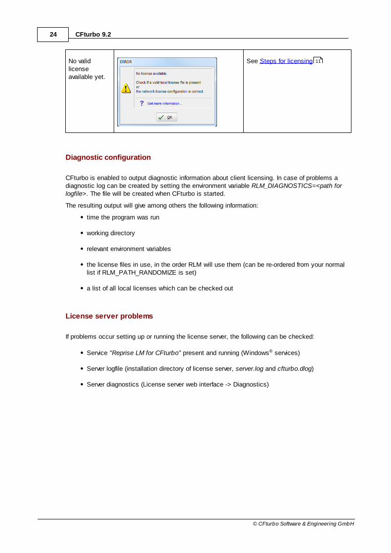
No validlicenseavailable yet.
See Steps for licensing
Diagnostic configuration
CFturbo is enabled to output diagnostic information about client licensing. In case of problems adiagnostic log can be created by setting the environment variable RLM_DIAGNOSTICS=<path forlogfile>. The file will be created when CFturbo is started.
The resulting output will give among others the following information:
time the program was run
working directory
relevant environment variables
the license files in use, in the order RLM will use them (can be re-ordered from your normallist if RLM_PATH_RANDOMIZE is set)
a list of all local licenses which can be checked out
License server problems
If problems occur setting up or running the license server, the following can be checked:
Service "Reprise LM for CFturbo" present and running (Windows® services)
Server logfile (installation directory of license server, server.log and cfturbo.dlog)
Server diagnostics (License server web interface -> Diagnostics)
11

25General
© CFturbo Software & Engineering GmbH
2.2 Batch mode
CFturbo can be executed in batch mode to modify designs without any screen display and userinteraction. This is essential for using CFturbo with optimization software.
Syntax:
cfturbo.exe -batch <batch file> [-verbose] [-export <interface name>]
Options:
-batch <batch file> Enables CFturbo batch mode. <batch file> can either be a CFturbo batch file (*.cft-batch) or aCFturbo project file (*.cft).
-verbose Display log output on the command line.
-export <interface name> If CFturbo is started with a CFturbo project file in batch mode, an export interface can be selected like in the batch file.
All other batch commands have to be defined in a file (<batch file>).
Batch file
The batch mode of CFturbo is controlled by an XML file. A template for a specific CFturbo project can be created via Project | Export | Basic | Batchmode template.
Due to a close relation between the CFturbo file format and the batch mode format, only template/batch mode files created with the same version as your CFturbo file should be used. After an updateof CFturbo a new template can be exported and the needed adjustments can be done.
The resulting batch mode template contains all modifiable values of the CFturbo project as XMLnodes supplemented by a short descriptions.
XML nodes of parameters that are not going to be changed can be deleted. The batch mode file alsocontains placeholder actions which must be completed with information related to file locations inthe file system and export interface of the batch mode output.
File structure:
<?xml version="1.0" standalone="yes"?>
75

26 CFturbo 9.2
© CFturbo Software & Engineering GmbH
<CFturboFile Version="9">
<CFturboBatchProject InputFile="<InputFileName>" />
<Updates>
[...]
</Updates>
<BatchAction .../>
</CFturboBatchProject>
</CFturboFile>
A batch-file can contain multiple elements of the CFturboBatchProject-type, each of which is
handling a specific CFturbo-project.This allows the combination of multiple batch mode templatesinto one batch mode file.
All XML-subelements are optional and can occur multiple times except for the Updates-block which
must occur once per CFturboBatchProject-element.
The InputFile-attribute of the CFturboBatchProject-element specifies the absolute path of
the CFturbo project file.
Batch actions
Two types of actions are available for further processing of the CFturbo projects loaded in batchmode:
<BatchAction Name="Export" ExportInterface="General" WorkingDir="c:\Examples\Myexports" BaseFileName="Pump1_9.1_all" ModelState="Solidsonly"/>
Is used to export the active component (point based exports) or all geometry elements visible inthe 3D-view visible when running CFturbo not in batch mode.
Attribute Value optional
Description
Name Export no Name of action
ExportInterface
e.g. "General" no Export interface to use
The following values are valid:
27General
© CFturbo Software & Engineering GmbH
AutoCAD BladeGenRtzt Catia
DXF General IGES
Inventor NumecaAG NumecaIGG
NX ProE PumpLinx
SimericsMP SolidWorks StarCCM
STEP STL TurboGrid
WorkingDir <existing path> yes Folder for exported files
BaseFileName
<filename> yes File name without extension
ModelState <existing modelstate>
yes Model state to select for export
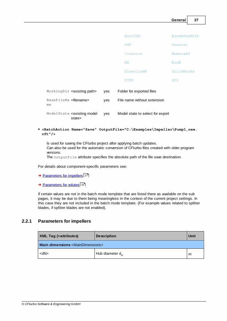
<BatchAction Name="Save" OutputFile="C:\Examples\Impeller\Pump1_new.cft"/>
Is used for saving the CFturbo project after applying batch updates. Can also be used for the automatic conversion of CFturbo files created with older programversions. The OutputFile attribute specifies the absolute path of the file save destination.
For details about component-specific parameters see:
Parameters for impellers
Parameters for volutes
If certain values are not in the batch mode template that are listed there as available on the subpages, it may be due to them being meaningless in the context of the current project settings. Inthis case they are not included in the batch mode template. (For example values related to splitterblades, if splitter blades are not enabled).
2.2.1 Parameters for impellers
XML Tag (+attributes) Description Unit
Main dimensions <MainDimensions>
<dN> Hub diameter dH m
27
31
28 CFturbo 9.2
© CFturbo Software & Engineering GmbH
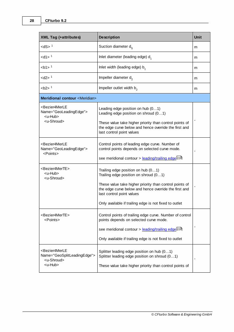
XML Tag (+attributes) Description Unit
<dS> 1 Suction diameter dS m
<d1> 1 Inlet diameter (leading edge) d1 m
<b1> 1 Inlet width (leading edge) b1 m
<d2> 1 Impeller diameter d2 m
<b2> 1 Impeller outlet width b2 m
Meridional contour <Meridian>
<Bezier4MerLEName="GeoLeadingEdge"> <u-Hub> <u-Shroud>
Leading edge position on hub (0…1)Leading edge position on shroud (0…1)
These value take higher priority than control points ofthe edge curve below and hence override the first andlast control point values
-
<Bezier4MerLEName="GeoLeadingEdge"> <Points>
Control points of leading edge curve. Number ofcontrol points depends on selected curve mode.
see meridional contour > leading/trailing edge
-
<Bezier4MerTE> <u-Hub> <u-Shroud>
Trailing edge position on hub (0…1)Trailing edge position on shroud (0…1)
These value take higher priority than control points ofthe edge curve below and hence override the first andlast control point values
Only available if trailing edge is not fixed to outlet
-
<Bezier4MerTE> <Points>
Control points of trailing edge curve. Number of controlpoints depends on selected curve mode.
see meridional contour > leading/trailing edge
Only available if trailing edge is not fixed to outlet
-
<Bezier4MerLEName="GeoSplitLeadingEdge"> <u-Shroud> <u-Hub>
Splitter leading edge position on hub (0…1)Splitter leading edge position on shroud (0…1)
These value take higher priority than control points of
-
226
226

29General
© CFturbo Software & Engineering GmbH
XML Tag (+attributes) Description Unit
the edge curve below and hence override the first andlast control point values
<Bezier4MerLEName="GeoSplitLeadingEdge"> <Points>
Control points of splitter leading edge curve. Numberof control points depends on selected curve mode.
see meridional contour > leading/trailing edge
-
<ListObjectBezier4Mer Name="GeoHub">
Contour segment of Hub contour containing set ofcontrol points. Number of control points depends onselected curve mode.
see meridional contour > Hub-Shroud contour(only available for Hub-Shroud design mode)
-
<ListObjectBezier4Mer Name="GeoShroud">
Contour segment of Shroud contour containing set ofcontrol points. Number of control points depends onselected curve mode.
see meridional contour > Hub-Shroud contour(only available for Hub-Shroud design mode)
-
<ListObjectBezier4Mer Name="GeoMiddleLine">
Midline contour containing a set of control points.Number of control points depends on selected curvemode.
see meridional contour > Design Modes(only available for Midline design mode)
-
Blade properties <BladeProperties>
<nBl> Number of blades nBl
-
<Count> Number of blade profiles -
<Beta1 Blade="0"> 2 Blade angles at leading edge β1 for each blade profile rad
<Beta2 Blade="0"> 2 Blade angles at trailing edge β2 for each blade profile rad
<Beta1 Blade="1"> 2 3 Splitter blade angles at leading edge β1,Spl
for each
blade profilerad
<Beta2 Blade="1"> 2 3Splitter blade angles at trailing edge β
2,Spl for each rad
226
216
216
211

30 CFturbo 9.2
© CFturbo Software & Engineering GmbH
XML Tag (+attributes) Description Unit
blade profile
<s1 Blade="0"> Main blade thickness - on small radius (LE) [Hub,Shroud]
m
<s2 Blade="0"> Main blade thickness - on large radius (TE) [Hub,Shroud]
m
<s1 Blade="1"> Splitter blade thickness - on small radius (LE) [Hub,Shroud]
m
<s2 Blade="1"> Splitter blade thickness - on large radius (LE) [Hub,Shroud]
m
<inc_RQ> Incidence - flow ratio Q_shockless/Q_BEP [Hub,Shroud]
%
<inc_i> Incidence angle [Hub,Shroud] rad
Mean lines <SkeletonLines>
<RelativeSplitterPosition> Splitter trailing edge position (tangential) betweenneighboring main blades
%
<Bezier3SL> 3 m,t-Bezier control points to modify wrap angle andblade shape
-
<BezierBetaSL> 3 Bezier points of β distribution for indirect modificationof blade shape
-
Blade profiles <BladeProfiles>
<BezFillProf Name="MBl"> Blade thickness distribution along main bladeprofiles.
Bezier curves for pressure- & suction side [PS, SS])
-
<BezFillProf Name="SBl"> Blade thickness distribution along splitter bladeprofiles.
Bezier curves for pressure- & suction side [PS, SS])
-
1 Make sure that main dimensions are not calculated automatically (see impeller main dimensions) to make these value available in batch mode. Save these changes into the Project file before
applying batch mode updates.
2 Make sure that 'automatic blade angle update' is deactivated in the blade property dialog tomake blade angles available in batch mode. Save these changes into the Project file before applyingbatch mode updates.
177
242

31General
© CFturbo Software & Engineering GmbH
3 Values for splitter blades are only available when splitters are not geometrically linked to mainblades. See blade properties .
2.2.2 Parameters for volutes
XML Tag (+attributes) Description Unit
Inlet definition <SpiralCasingBC>
<FQ> Flow factor FQ -
<MerInlet>Inlet geometry (Positions and Offsets for Hub andShroud). Used to change Inlet diameter (d4) andInlet width (b4).
m
Diffuser <SpiralCasingDiff>
<Bezier4Diff> <H6>
Diffuser height (h6). (See Diffuser ) m
<Diameter>or<Rectangle>
Dimensions of the 'End cross-section'. Depending on the used shape it either specifies aDiameter for circular end cross-sections or widthand height for rectangular end cross sections
(See Diffuser )
m
2.2.3 Exit Codes
CFturbo provides the following exit codes, which report the result of the batch run:
Exit Code Description
0 No errors or warnings occurred during batch run.
1 Last batch run was completed with warnings but no errors.
2 Last batch run was completed with errors.
235
333
333

32 CFturbo 9.2
© CFturbo Software & Engineering GmbH
2.2.4 Example
The example of a CFturbo batch file below, changes the blade number of the Pump1 exampleproject.
Subsequently the modified project gets exported as geometry export as well as saved into theCFturbo project file "Pump1_mod.cft".
<?xml version="1.0" standalone="yes"?>
<CFturboFile Version="9">
<CFturboBatchProject InputFile="C:\Testing\Pump1.cft">
<Updates>
<CFturboProject Type="Object">
<CFturboDesign_RadialImpeller Type="Object" Name="<Radial
Impeller>" Info="Cfturbo GmbH" Index="0" Desc="CFturbo component">
<BladeProperties Type="Object" Desc="Blade properties">
<nBl Type="Integer" Desc="Number of blades">7</nBl>
</BladeProperties>
</CFturboDesign_RadialImpeller>
</CFturboProject>
</Updates>
<BatchAction Name="Export" ExportInterface="General" WorkingDir="C:
\Testing\" BaseFileName="Pump1_9.1_all" AllComponents="1"/>
<BatchAction Name="Export" ExportInterface="General" WorkingDir="C:
\Testing\" BaseFileName="Pump1_9.1">
<ExportComponents Type="Array" Count="1">
<Value Type="Integer" Index="0">0</Value>
</ExportComponents>
</BatchAction>
<BatchAction Name="Export" ExportInterface="STEP" BaseFileName="Pump1_9.1"
ModelState="Solids only">
<ExportComponents Type="Array" Count="1">
<Value Type="Integer" Index="0">0</Value>
</ExportComponents>
</BatchAction>
<BatchAction Name="Save" OutputFile="pump1_mod.cft"/>
</CFturboBatchProject>
</CFturboFile>
33General
© CFturbo Software & Engineering GmbH
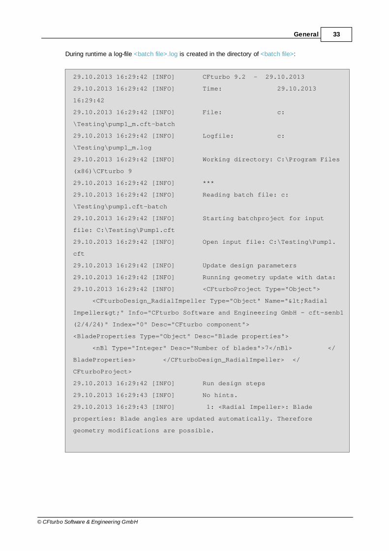
During runtime a log-file <batch file>.log is created in the directory of <batch file>:
29.10.2013 16:29:42 [INFO] CFturbo 9.2 - 29.10.2013
29.10.2013 16:29:42 [INFO] Time: 29.10.2013
16:29:42
29.10.2013 16:29:42 [INFO] File: c:
\Testing\pump1_m.cft-batch
29.10.2013 16:29:42 [INFO] Logfile: c:
\Testing\pump1_m.log
29.10.2013 16:29:42 [INFO] Working directory: C:\Program Files
(x86)\CFturbo 9
29.10.2013 16:29:42 [INFO] ***
29.10.2013 16:29:42 [INFO] Reading batch file: c:
\Testing\pump1.cft-batch
29.10.2013 16:29:42 [INFO] Starting batchproject for input
file: C:\Testing\Pump1.cft
29.10.2013 16:29:42 [INFO] Open input file: C:\Testing\Pump1.
cft
29.10.2013 16:29:42 [INFO] Update design parameters
29.10.2013 16:29:42 [INFO] Running geometry update with data:
29.10.2013 16:29:42 [INFO] <CFturboProject Type="Object">
<CFturboDesign_RadialImpeller Type="Object" Name="<Radial
Impeller>" Info="CFturbo Software and Engineering GmbH - cft-senb1
(2/4/24)" Index="0" Desc="CFturbo component">
<BladeProperties Type="Object" Desc="Blade properties">
<nBl Type="Integer" Desc="Number of blades">7</nBl> </
BladeProperties> </CFturboDesign_RadialImpeller> </
CFturboProject>
29.10.2013 16:29:42 [INFO] Run design steps
29.10.2013 16:29:43 [INFO] No hints.
29.10.2013 16:29:43 [INFO] 1: <Radial Impeller>: Blade
properties: Blade angles are updated automatically. Therefore
geometry modifications are possible.
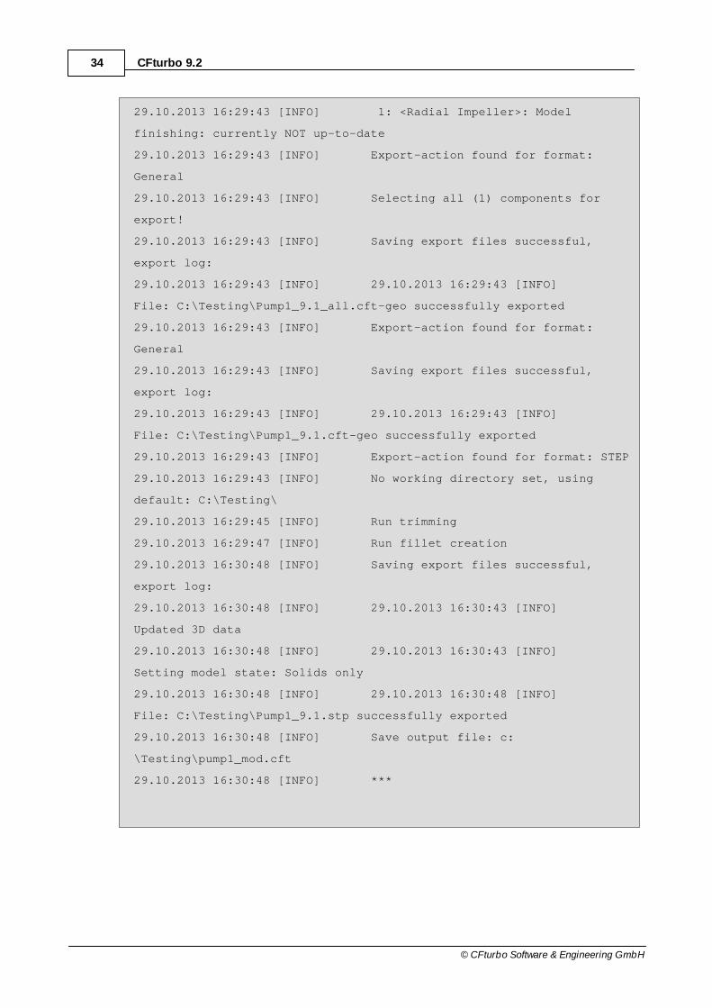
34 CFturbo 9.2
© CFturbo Software & Engineering GmbH
29.10.2013 16:29:43 [INFO] 1: <Radial Impeller>: Model
finishing: currently NOT up-to-date
29.10.2013 16:29:43 [INFO] Export-action found for format:
General
29.10.2013 16:29:43 [INFO] Selecting all (1) components for
export!
29.10.2013 16:29:43 [INFO] Saving export files successful,
export log:
29.10.2013 16:29:43 [INFO] 29.10.2013 16:29:43 [INFO]
File: C:\Testing\Pump1_9.1_all.cft-geo successfully exported
29.10.2013 16:29:43 [INFO] Export-action found for format:
General
29.10.2013 16:29:43 [INFO] Saving export files successful,
export log:
29.10.2013 16:29:43 [INFO] 29.10.2013 16:29:43 [INFO]
File: C:\Testing\Pump1_9.1.cft-geo successfully exported
29.10.2013 16:29:43 [INFO] Export-action found for format: STEP
29.10.2013 16:29:43 [INFO] No working directory set, using
default: C:\Testing\
29.10.2013 16:29:45 [INFO] Run trimming
29.10.2013 16:29:47 [INFO] Run fillet creation
29.10.2013 16:30:48 [INFO] Saving export files successful,
export log:
29.10.2013 16:30:48 [INFO] 29.10.2013 16:30:43 [INFO]
Updated 3D data
29.10.2013 16:30:48 [INFO] 29.10.2013 16:30:43 [INFO]
Setting model state: Solids only
29.10.2013 16:30:48 [INFO] 29.10.2013 16:30:48 [INFO]
File: C:\Testing\Pump1_9.1.stp successfully exported
29.10.2013 16:30:48 [INFO] Save output file: c:
\Testing\pump1_mod.cft
29.10.2013 16:30:48 [INFO] ***

35General
© CFturbo Software & Engineering GmbH
29.10.2013 16:30:48 [INFO] Batch mode terminated. (01:08.160
min)
2.3 Project structure and interfaces
A CFturbo project describes a complete single-stage machine or a single stage of a multi-stagemachine. Flow-conducting parts of the machine can be designed by CFturbo.
Project types
The follwing project/ machine types are available:
Pump
Ventilator
Compressor
Turbine
Project structure
A project consists of the global parts
Project information
Global setup
Performance prediction
Exp ort
and the single component parts of the assembly. The following components are available:
1 Impeller on any position
1 Volute as last component
any number of Stators (vaned or unvaned)
Components can be added directly in the components view or via the project menu .
58
58
64
70 70
147 119

36 CFturbo 9.2
© CFturbo Software & Engineering GmbH
Interfaces between components
Interfaces exist between neighboring components describing their coupling. The following couplingtypes are available:
Coupling in flow direction (Default)
Inlet cross section of a component is defined by the outlet crosssection of previous component.
Coupling reverse flow direction

37General
© CFturbo Software & Engineering GmbH
Outlet cross section of a component is defined by the inlet crosssection of next component.
Interface coupling can be adjusted in the component view directly at the interface positionbetween neighboring components.
The impeller as the core component of a machine has primary interface sides both at inlet and outletside.
2.3.1 Interface definition
The sketch illustrates the general layout of an interface between 2 neighboring components:
Primary / Secondary
One side (component) of the interface is primary always, the other one is secondary. The primaryside determines the position of the interface (red in the sketch), the secondary has to align on the
146

38 CFturbo 9.2
© CFturbo Software & Engineering GmbH
primary side. Each interface side can define an offset to the interface optionally.
If the geometry of the primary component and therefore the position of the interface is changing, thenthe component with the secondary interface is adjusted automatically. If a component is deactivated(see Active/ Rename/ Delete ), then no adjustment will be effected - therefore an overlapping ofneighboring components is possible, which is illustrated by a warning (see Components ).
Interface definition
The interface definition at volute inlet as well as at stator inlet and outlet is made in anuniform manner.
CouplingInformation to interface coupling direction
Inlet/ outlet interfaceInterfaces position at hub and shroud side(deactivated for secondary interface side)
? ? Coordinate transfer from geometry tointerface and reverse
Inlet/ outletGeometry definition optionally by- Points on Hub & Shroud- Point on Center line, width and angle
Alternatively absolute coordinates or anOffset can be used, which areautomatically converted into each other.
Rotor-Stator-Interface
Rotor-Stator-Interface (RSI) at impeller outlet can be defined in the CFD-Setup of the impeller,otherwise it's located directly on the impeller outlet.
Flow direction (angle)
Beside the geometrical information the flow direction is an important interface property. The flowdirection at the component inlet is defined by the flow direction at the outlet of the upstreamcomponent (predecessor). Outlet flow direction of a component is determined by its blade or byconstant swirl for vaneless components.
120
146
314 301 302
280

39General
© CFturbo Software & Engineering GmbH
The first component of the project has no predecessor and gets the flow direction information frompre-swirl definition in the Global setup .
2.4 Graphical dialogs
Most component design step dialogs contain 2D graphical representation. The user interface isuniform concerning the following topics.
Diagram popup menu
All graphical representations are made in diagrams that are automatically scaled according todisplayed objects. All diagrams have a popup menu (right click on empty diagram area) with basicfunctions. Alternatively you can use the buttons on the top side of the diagram:
Zoom window by mouse
Fit view
Lens magnification
Copy to clipboard
Save diagram as BMP, GIF, JPG, PNG or WMF
Add any polyline from file (x,y points) to compare different curves
Measure distance
Configure diagram
Context sensitive popup menus
If the mouse cursor is moved over a graphical object (e.g. polyline, Bezier point) then this ishighlighted by color or by increased line width. Right mouse click is now related to this object anddoes open a special popup menu or a small dialog window for data input.
Bezier curves are used for geometrical contours by default. This continuous polylines are describedby the position of a few Bezier points. Therefore a simple modification of the curve is possible but onthe other hand the numerical representation of the curve is accurate.
58
40 CFturbo 9.2
© CFturbo Software & Engineering GmbH
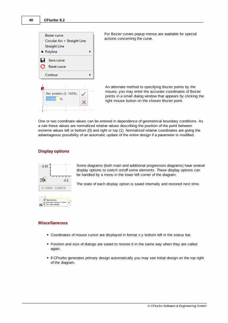
For Bezier curves popup menus are available for specialactions concerning the curve.
An alternate method to specifying Bezier points by themouse, you may enter the accurate coordinates of Bezierpoints in a small dialog window that appears by clicking theright mouse button on the chosen Bezier point.
One or two coordinate values can be entered in dependence of geometrical boundary conditions. Asa rule these values are normalized relative values describing the position of the point betweenextreme values left or bottom (0) and right or top (1). Normalized relative coordinates are giving theadvantageous possibility of an automatic update of the entire design if a parameter is modified.
Display options
Some diagrams (both main and additional progression diagrams) have severaldisplay options to switch on/off some elements. These display options canbe handled by a menu in the lower left corner of the diagram.
The state of each display option is saved internally and restored next time.
Miscellaneous
Coordinates of mouse cursor are displayed in format x:y bottom left in the status bar.
Position and size of dialogs are saved to restore it in the same way when they are calledagain.
If CFturbo generates primary design automatically you may see Initial design on the top rightof the diagram.
41General
© CFturbo Software & Engineering GmbH
If numerical values are entered in tables, then a new value is only activated and the diagramis updated if the <Enter> key is pressed or a new cell of the table is selected.
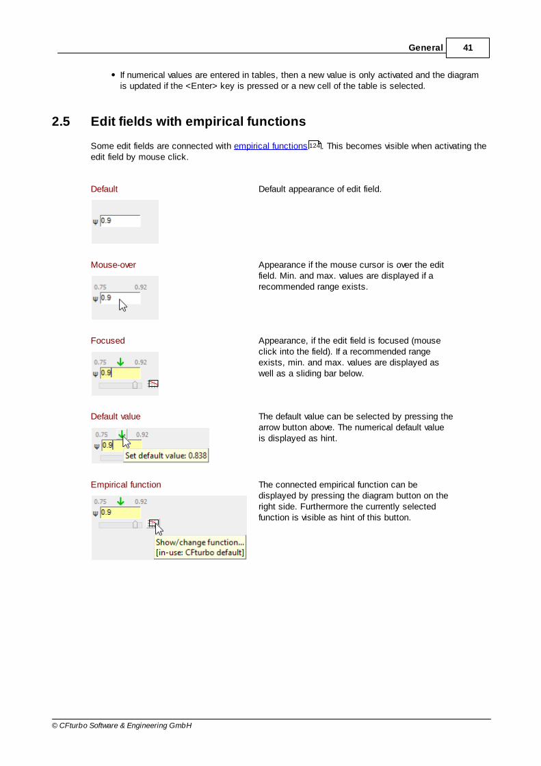
2.5 Edit fields with empirical functions
Some edit fields are connected with empirical functions . This becomes visible when activating theedit field by mouse click.
Default Default appearance of edit field.
Mouse-over Appearance if the mouse cursor is over the editfield. Min. and max. values are displayed if arecommended range exists.
Focused Appearance, if the edit field is focused (mouseclick into the field). If a recommended rangeexists, min. and max. values are displayed aswell as a sliding bar below.
Default value The default value can be selected by pressing thearrow button above. The numerical default valueis displayed as hint.
Empirical function The connected empirical function can bedisplayed by pressing the diagram button on theright side. Furthermore the currently selectedfunction is visible as hint of this button.
124

Part
III

43Start
© CFturbo Software & Engineering GmbH
3 Start
After starting the program you see the following screen:
Create new project
Here you can create a new project by selecting the desired machine type:
Pump
Ventilator
Compressor
Turbine
These 4 buttons correspond to the menu item File/ New .
After creating a new project the Global Setup dialog is startingautomatically.
55
58

44 CFturbo 9.2
© CFturbo Software & Engineering GmbH
Afterwards several components can be added to the project.
Open existing project
Here you can select existing projects:
Open any CFturbo project (*.cft) via file opening dialog(corresponds to the menu item "File/ Open" )
Open one of the CFturbo default examples from the installationdirectory
119
56

Part
IV

46 CFturbo 9.2
© CFturbo Software & Engineering GmbH
4 Opened project
After creating a new design or opening an existing project the main window looks as shown below:
On top you can find the ribbon style menu providing access to all functionality.
The CFturbo application window is divided into three main areas:
a) Component list on the left side
This ordered list contains an icon for each component of the project. The currently selectedcomponent is framed.
Clicking on the icon selects the component (alternatively you can click on component in the meridional view ).
After selecting a component, the ribbon changes to the project tab or to the specific one for thiscomponent type (configurable, see General ). The context menu of the icons allows (de)activating,renaming and deleting the component.
53
146
132

47Opened project
© CFturbo Software & Engineering GmbH
The following component types are possible:
Radial or mixed-flow Impeller
Stator (vaned or unvaned)
Volute
b)Three alternative views in the central part
see Views
c) Message panel on the right side
The message panel shows errors (red), warnings (orange) and information (green) for all componentsof the project. The design step causing the message is also shown.It depends on the opinion of the user to accept warnings or to modify the design by adequate actionsto avoid them. Reasons for errors should be eliminated.
The type of a message (warning/ error/information) is shown when hovering themouse cursor over it.
If a help link is available providingadditional information concerning themessage, a question mark is shown nextto the cursor. The help can then be openedby clicking on the message. If thecomponent the message belongs to iscurrently not selected, the component canbe selected optionally.
145

Part
V
49Component design process
© CFturbo Software & Engineering GmbH
5 Component design process
The design process for CFturbo project components requires the completion of a specific sequenceof obligatory design steps for each component type (see impeller , volute , stator ).
After completing a components basic design process, optional design steps related to modelfinishing and CFD setup become available.
Each design step comes with its own dialog that can be accessed via the component specificmenus or the components context menu in the meridian view.
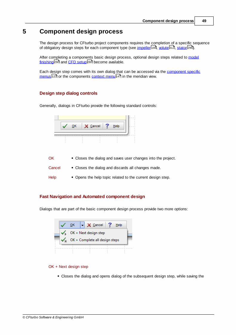
Design step dialog controls
Generally, dialogs in CFturbo provide the following standard controls:
OK Closes the dialog and saves user changes into the project.
Cancel Closes the dialog and discards all changes made.
Help Opens the help topic related to the current design step.
Fast Navigation and Automated component design
Dialogs that are part of the basic component design process provide two more options:
OK + Next design step
Closes the dialog and opens dialog of the subsequent design step, while saving the
166 312 296
290 280
123 147
50 CFturbo 9.2
© CFturbo Software & Engineering GmbH
user changes into the project.
This feature enables you to quickly navigate all basic design steps in the correct orderto apply small modifications faster and more comfortably
This option is only available, if the selected component has a next design step that ismandatory. Otherwise, it's grayed out.
OK + Complete all design steps
Closes the dialog and saves user changes into the project. Finally, it completes allsubsequent mandatory design steps of the selected component with default values.
This option is only available if the selected component has a next design step that hasnever been completed or has been removed previously. Otherwise, it's grayed out.
You may use this option as soon as the main dimensions and interfaces of acomponent are defined to get to a preliminary automatic design within seconds. Youcan change all design parameters according to your requirements later on.
The automatic design may fail or lead to unsatisfactory results if global project settingsand/or previously completed design steps are unsound. In this case you will be informedabout the issue via warnings in the message panel or a message box.
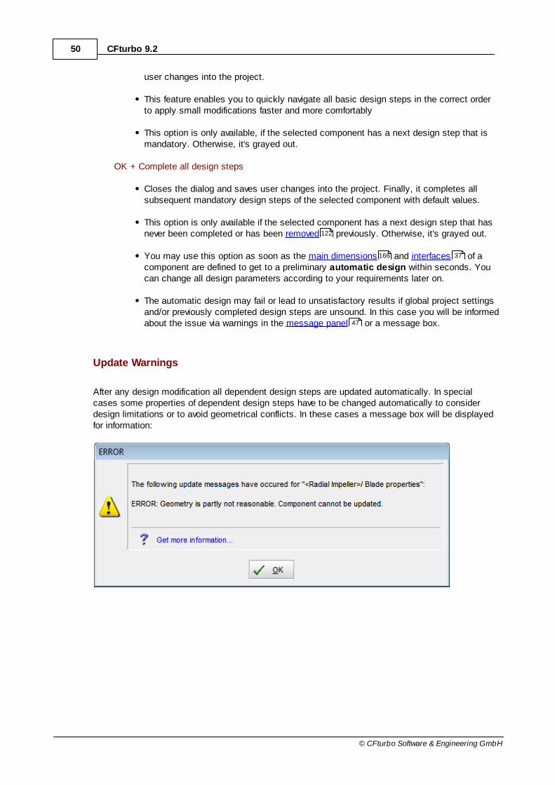
Update Warnings
After any design modification all dependent design steps are updated automatically. In specialcases some properties of dependent design steps have to be changed automatically to considerdesign limitations or to avoid geometrical conflicts. In these cases a message box will be displayedfor information:
122
166 37
47

51Component design process
© CFturbo Software & Engineering GmbH
These information is also displayed in the Messages area right in the main form.
See also Opened project/ message panel
Usually you can find more information about amessage in the online help by clicking on its text.
47

Part
VI
53Menu
© CFturbo Software & Engineering GmbH
6 Menu
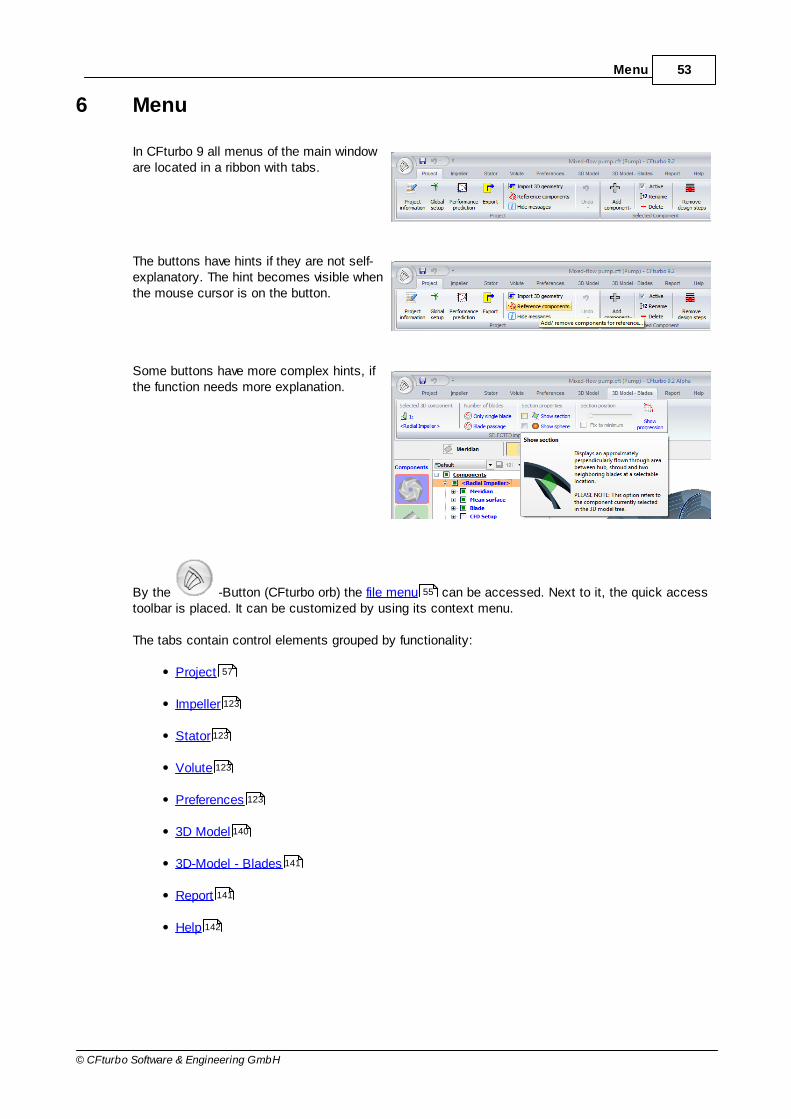
In CFturbo 9 all menus of the main windoware located in a ribbon with tabs.
The buttons have hints if they are not self-explanatory. The hint becomes visible whenthe mouse cursor is on the button.
Some buttons have more complex hints, ifthe function needs more explanation.
By the -Button (CFturbo orb) the file menu can be accessed. Next to it, the quick accesstoolbar is placed. It can be customized by using its context menu.
The tabs contain control elements grouped by functionality:
Project
Impeller
Stator
Volute
Preferences
3D Model
3D-Model - Blades
Report
Help
55
57
123
123
123
123
140
141
141
142
54 CFturbo 9.2
© CFturbo Software & Engineering GmbH
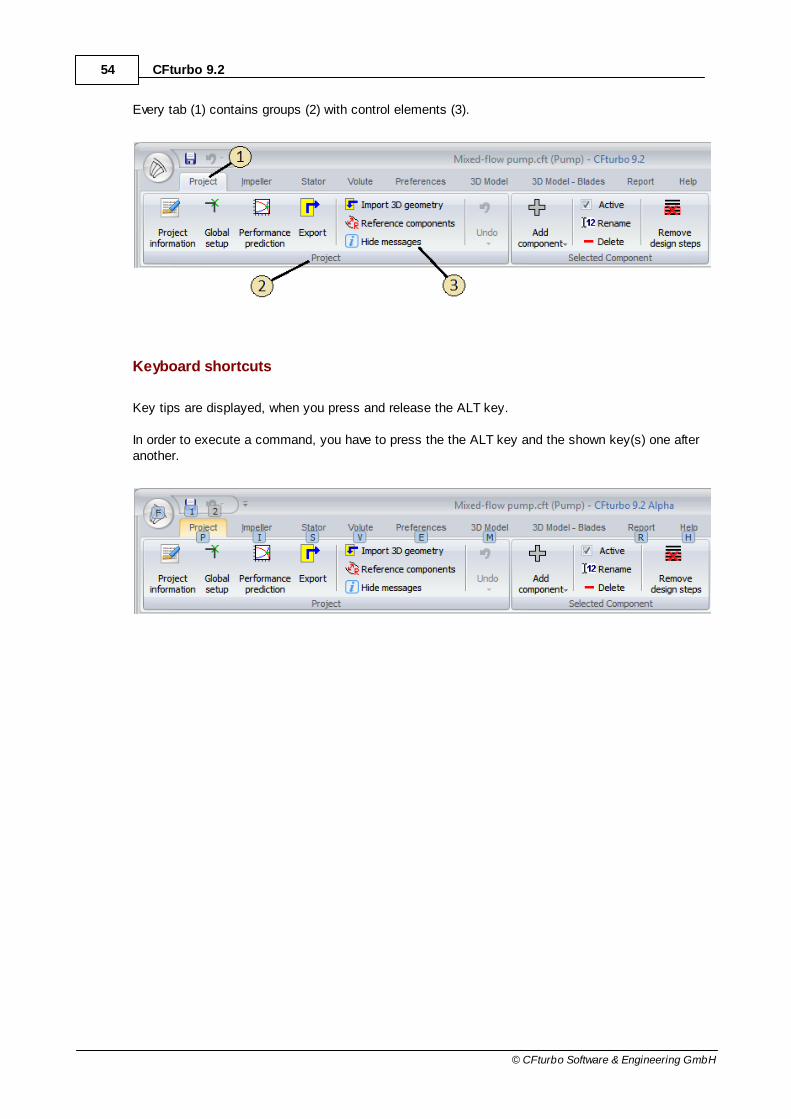
Every tab (1) contains groups (2) with control elements (3).
Keyboard shortcuts
Key tips are displayed, when you press and release the ALT key.
In order to execute a command, you have to press the the ALT key and the shown key(s) one afteranother.

55Menu
© CFturbo Software & Engineering GmbH
6.1 File
The file menu can be found on the leftborder of the ribbon and contains thebasic file operations.
Right behind the menu buttons you canopen one of the recently used files byselecting it from the list.
This list is also available in the mainwindow directly after starting the program(see Start ).
6.1.1 Create new design
? File | New
When creating a new project one of the following project types can be selected:
Pump
Ventilator
Compressor
43
56 CFturbo 9.2
© CFturbo Software & Engineering GmbH
Turbine
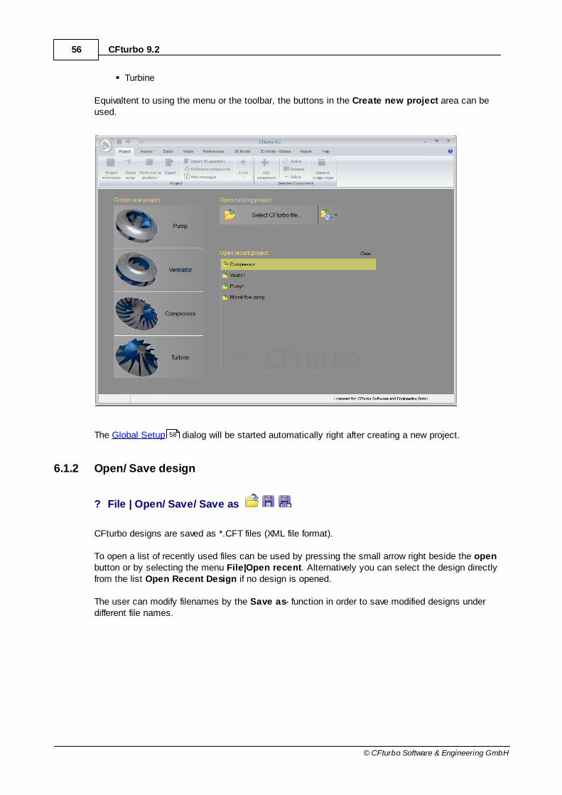
Equivaltent to using the menu or the toolbar, the buttons in the Create new project area can beused.
The Global Setup dialog will be started automatically right after creating a new project.
6.1.2 Open/ Save design
? File | Open/ Save/ Save as
CFturbo designs are saved as *.CFT files (XML file format).
To open a list of recently used files can be used by pressing the small arrow right beside the openbutton or by selecting the menu File|Open recent. Alternatively you can select the design directlyfrom the list Open Recent Design if no design is opened.
The user can modify filenames by the Save as- function in order to save modified designs underdifferent file names.
58

57Menu
© CFturbo Software & Engineering GmbH
6.2 Project
A project can consist of several components (see Project structure and interfaces ). Allcomponents can be designed separately, whereas they influence each other on the interfaces due togeometrical constraints and fluidic coupling.
The Project menu contains those actions, that are related to the whole project (group Project ) orto the currently selected component (group Selected Component ).
6.2.1 Project
The group Project contains all those actions that are related to the whole project.
Project information
Global setup
Performance prediction
Export
Import 3D geometry
Reference components
Show/Hide messages
Undo
35
57
119
58
58
64
70
115
115
118
118

58 CFturbo 9.2
© CFturbo Software & Engineering GmbH
6.2.1.1 Project information
? Project | Project | Project Information
For identification of the project can be specified:
Project name
Classification (e.g. version or sub name)
User name
Comments
This information is not mandatory and should support the identification of CFturbo projects &sessions.
The working directory, the creation date and the date of last modification are displayed too.
6.2.1.2 Global setup
? Project | Project | Global setup
Here the global project settings are defined valid for all components.
59Menu
© CFturbo Software & Engineering GmbH
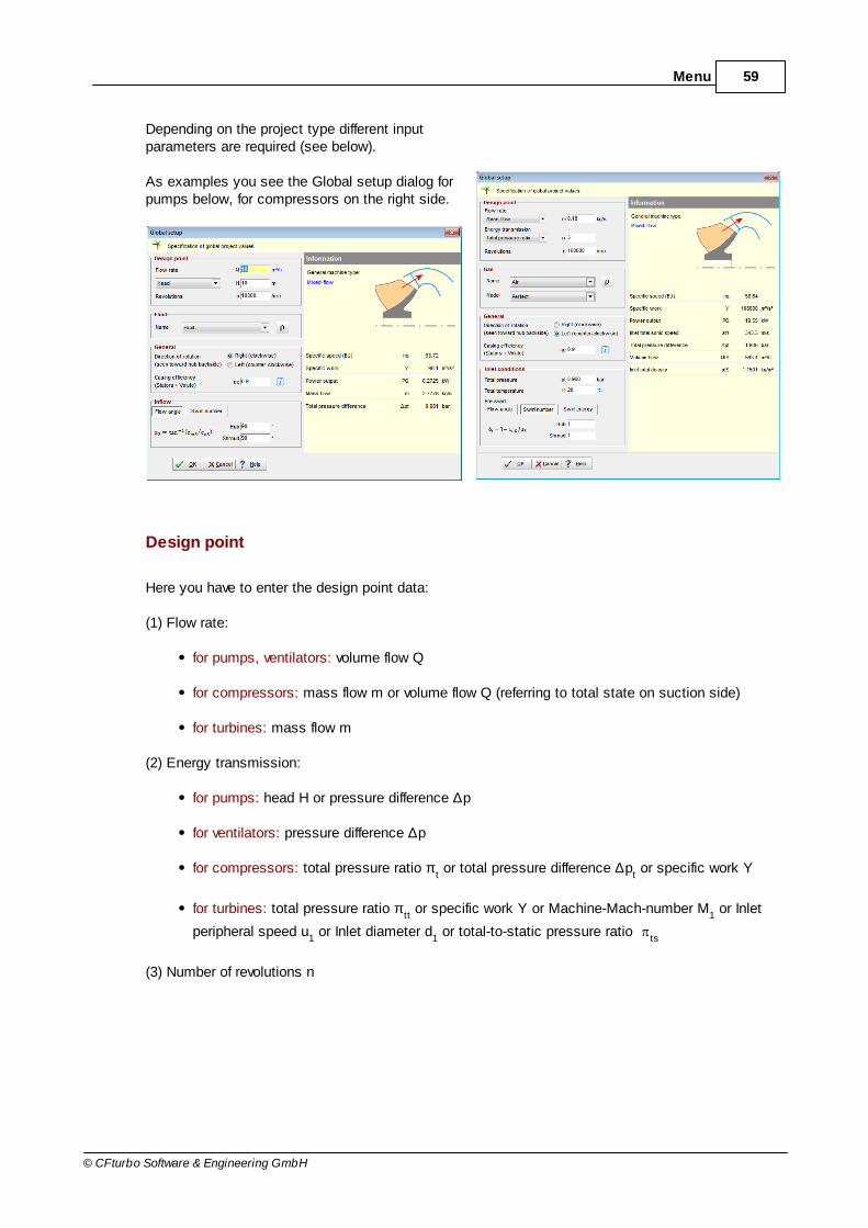
Depending on the project type different inputparameters are required (see below).
As examples you see the Global setup dialog forpumps below, for compressors on the right side.
Design point
Here you have to enter the design point data:
(1) Flow rate:
for pumps, ventilators: volume flow Q
for compressors: mass flow m or volume flow Q (referring to total state on suction side)
for turbines: mass flow m
(2) Energy transmission:
for pumps: head H or pressure difference ∆p
for ventilators: pressure difference ∆p
for compressors: total pressure ratio πt or total pressure difference ∆p
t or specific work Y
for turbines: total pressure ratio πtt or specific work Y or Machine-Mach-number M
1 or Inlet
peripheral speed u1 or Inlet diameter d
1 or total-to-static pressure ratio
ts
(3) Number of revolutions n

60 CFturbo 9.2
© CFturbo Software & Engineering GmbH
General
Here you can define the rotational direction of the impeller seen from the drive side (axial view tobackside of hub).
Furthermore the Casing efficiency can be defined optionally, which contains all flow losses in nonerotating components and can be used for overall efficiency calculation in connection with the impellerefficiency.
Fluid
Here the fluid has to be defined.
One has to select one of the predefined fluids. The list of existing fluids can be modified in the fluidmanager .
Inflow [ for pumps, ventilators, compressors only ]
Here you may define the inflow swirl at hub and shroud. You have the following possibilities:
Flow angle Swirl number Swirl energy number
uSmSS ccarctan SuSr uc1 Ycu uSSY
Positive swirl
Negative swirl
No swirl
αS < 90°
αS > 90°
αS = 90°
δr < 1
δr > 1
δr = 1
δY > 0
δY < 0
δY = 0
Negative swirl is increasing the head and may often have no good affect to the suction behavior.Inflow through a straight pipe usually leads to swirl-free flow.
The different parameters can be converted:
S2
N2
S2
SS
mSr
tannddd
Q41
tanu
c1
2s
Yr
u
Y1
Y
1u r2
sY
129
61Menu
© CFturbo Software & Engineering GmbH
The conversion r -
S is only valid for certain diameters d
N and d
S.
Inlet conditions [ for compressors only ]
Here you have to define the total state on suction side by total pressure pt and total temperature T
t.
In-/ outlet conditions [ for turbines only ]
Here the static pressure at the suction flange (pressure in the connection flange of the work pieceattached to the turbine at the outlet) as well as the total temperature at the inlet has to be specified.
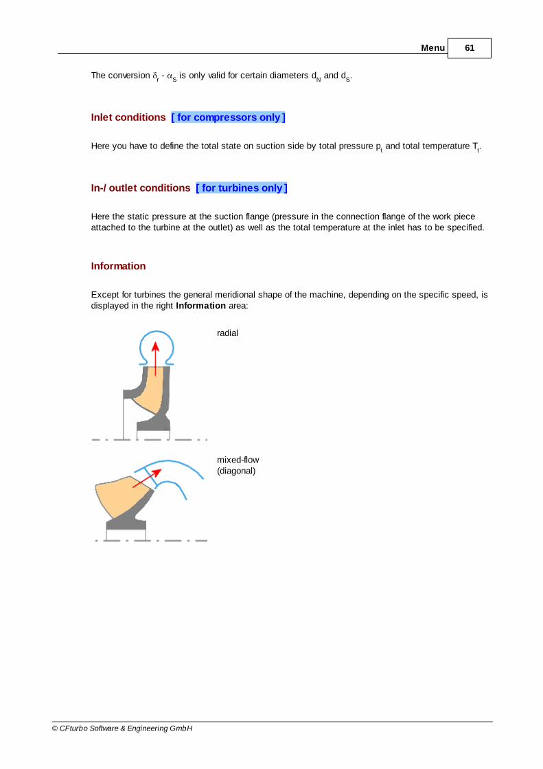
Information
Except for turbines the general meridional shape of the machine, depending on the specific speed, isdisplayed in the right Information area:
radial
mixed-flow(diagonal)
62 CFturbo 9.2
© CFturbo Software & Engineering GmbH
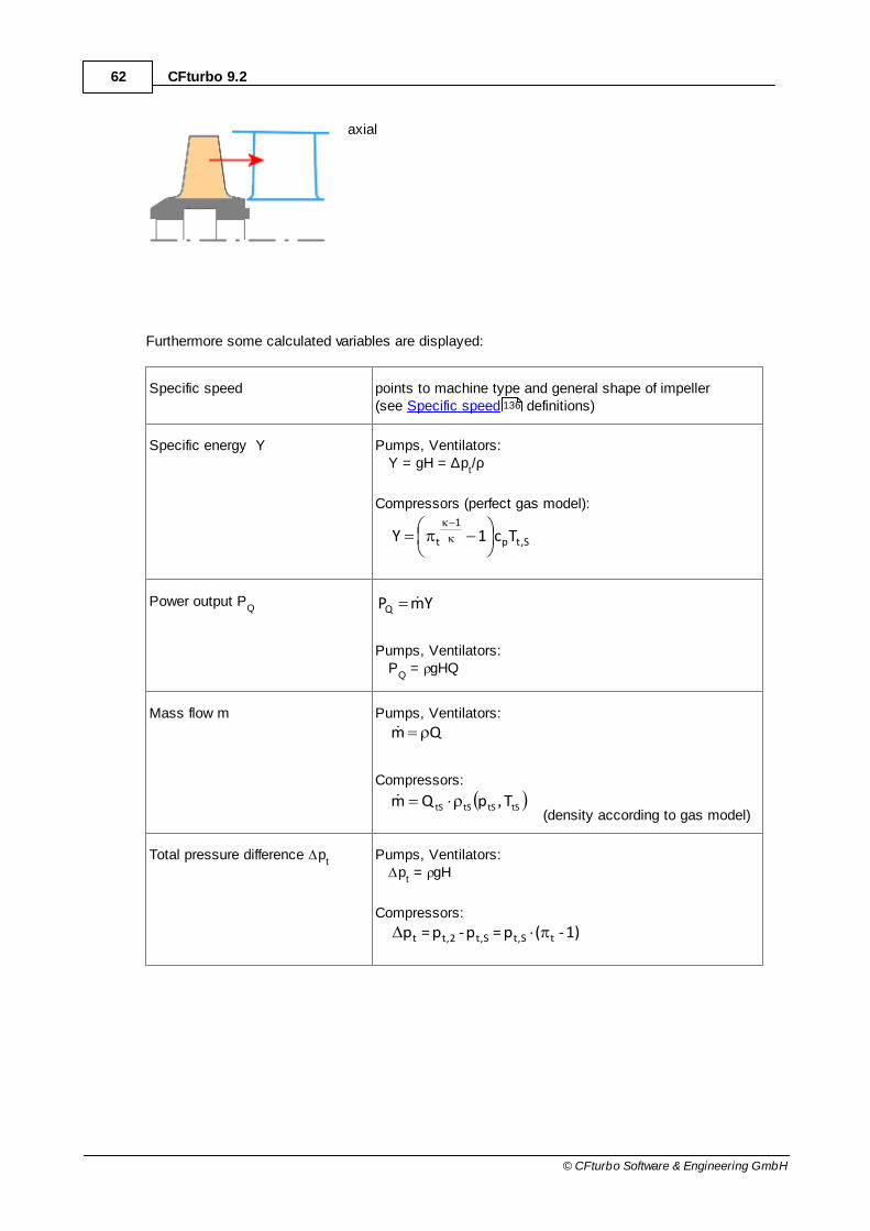
axial
Furthermore some calculated variables are displayed:
Specific speed points to machine type and general shape of impeller(see Specific speed definitions)
Specific energy Y Pumps, Ventilators: Y = gH = ∆p
t/ρ
Compressors (perfect gas model):
S,tp
1
t Tc1Y
Power output PQ YmPQ
Pumps, Ventilators: P
Q = gHQ
Mass flow m Pumps, Ventilators:
Qm
Compressors:
tStStStS TpQm ,
(density according to gas model)
Total pressure difference pt
Pumps, Ventilators: p
t = gH
Compressors:
1)-(p=p-p=p tt,St,St,2t
136

63Menu
© CFturbo Software & Engineering GmbH
Compressor:
Total pressure ratio pp= t,St,2t
Inlet speed of sound (total) S,t1,t TZRa(perfect gas model)
Volume flow (total)tStStS
tSTp
mQ
, (density according to gas model)
Inlet density (total) tStStStS Tp , (density according to gas model)
Outlet density (total) 2222 , tttt Tp (density according to gas model)
Outlet temperature (total)tSp
tS2tTc
Y1TT
(perfect gas model)
Turbine:
Total speed of sound at inlet at1 1tGas1t TZRa
(perfect gas model)
General remarks
In general for cost reasons single-stage & single-intake machines are preferred covering a range ofabout 10 < nq < 400.
In exceptional cases it may become necessary to design an impeller for extremely low specificspeed values (nq < 10). These impellers are characterized by large impeller diameters and lowimpeller widths. The ratio of free flow cross section area to wetted surfaces becomes unfavorableand is causing high frictional losses. To prevent this one may increase either rotational speed n orflow rate Q if possible. An alternative solution could be the design of a multi-stage machinereducing the energy transmission of the single-stage.

64 CFturbo 9.2
© CFturbo Software & Engineering GmbH
If especially high specific speed values (nq > 400) do occur one can reduce rotational speed n orflow rate Q if feasible. Another option would be to operate several single-stage machines - having alower nq - in parallel.
Please note: CFturbo® is preferably used between 10 < nq < 150 – radial and mixed-flowimpellers.
6.2.1.3 Performance prediction
? Project | Project | Performance prediction
The Performance prediction is an empirical based estimation of the performance map of themachine.
Please note: This is an estimation. The actual performance may differ from the prediction.
General

65Menu
© CFturbo Software & Engineering GmbH
A performance curve of the current design is estimated on the basis of the Euler-Equation:
1u12u2th cucug
1H and 1122 uu
thth cucu
pY respectively.
Kinds of losses
There are different kinds of losses that are considered in different curves:
Kind Description Parameter
Decreasedpower
Based on the Euler-Equation and the decreased powerthat is calculated in the Blade properties . In thedesign point the decreased power line is shifted by apressure head loss equivalent to the decreased power(H
Decr=H
th-∆H
Decr). The decreased power line can be
parallel to the Euler-Line as well as positioned thatway, that it intersects the Euler-Line at ∆p = 0.
cl:
cl = 1...parallel position,
cl = 0...intersection withEuler-Line at ∆p = 0.
Hydrauliclosses
Based on the Euler-Line including the decreasedpower minus the losses due to friction. Yields adownwards opened parabola, that touches thedecreased power curve at Q = 0.
:
Generalapproach:
2QFHHydr
F:
Flow factor thatconsiders thegeometry of thecomponent(inlet and outletarea)
25.0
100
outin AAgF
Turbulenceandseparation
Includes all the effects listed above plus turbulenceand separation losses at the inlet and outlet. Yields adownwards opened parabola. It touches the curve, inwhich decreased power and hydraulic losses areconsidered, in the point of shockless flow Q
opt. Here
the flow direction is tangential towards the leadingedge.
ct:
Generalapproach:
2
optTurb QQFctH
The display of resulting performance curves can be toggled by the check box "All performance
curves" ( display options lower corner in the left). In case the curves are to be hidden only theactual performance curve (red color) considering all losses will be visible.
A loss coefficient, that describes the hydraulic losses, can be calculated by pressing "Calculate ζ"in a way, that as a result the actual performance curve (red) of the flow efficiency will go through thebest point.
234

66 CFturbo 9.2
© CFturbo Software & Engineering GmbH
Settings
Energy and flow rate variables plusflow rate limits
Coefficients influencing thedecreased power (cl) and thehydraulic as well as turbulentlosses ( ct)
Additional curves with differentspeeds and diameter plussystem characteristic
Variables
All types of turbo machines have in common: The characteristics can be displayed in a diagram withdimensions as well as without dimensions.
Variable
Pump Ventilator Compressor Turbine
H head - - -
∆p total pressure difference
work coefficient
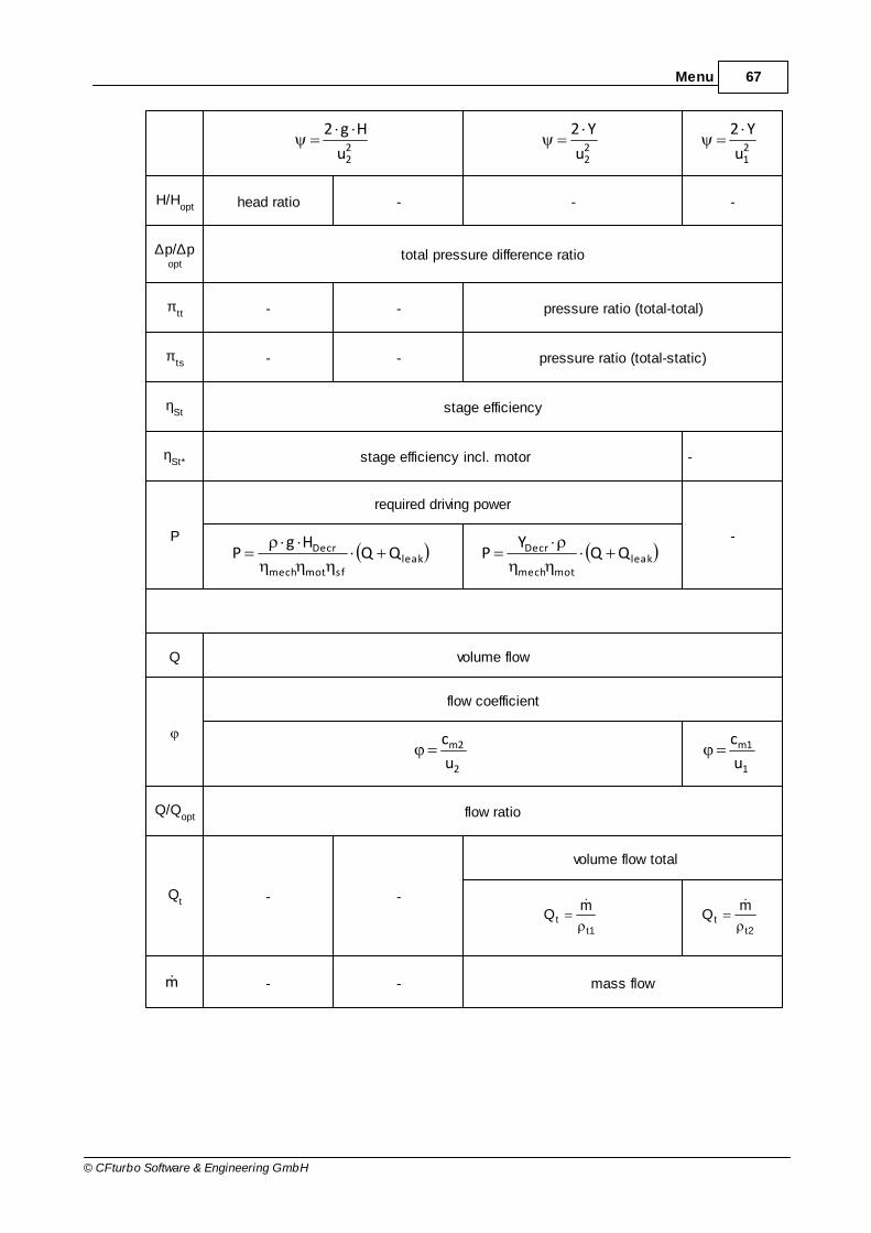
67Menu
© CFturbo Software & Engineering GmbH
22u
Hg222u
Y221u
Y2
H/Hopt head ratio - - -
∆p/∆popt
total pressure difference ratio
πtt - - pressure ratio (total-total)
πts - - pressure ratio (total-static)
ηSt stage efficiency
ηSt* stage efficiency incl. motor -
P
required driving power
-
leaksfmotmech
Decr QQHg
P leakmotmech
Decr QQY
P
Q volume flow
flow coefficient
2
2m
u
c
1
1m
u
c
Q/Qopt flow ratio
Qt - -
volume flow total
t1t
mQ
t2t
mQ
m - - mass flow
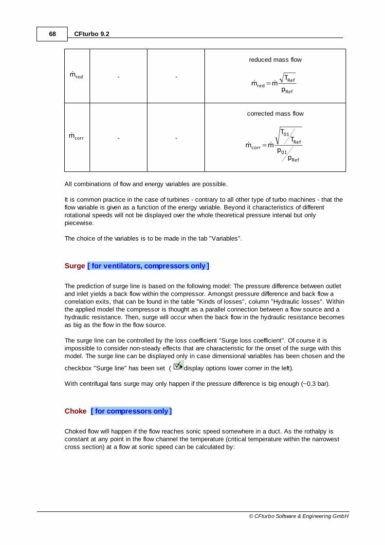
68 CFturbo 9.2
© CFturbo Software & Engineering GmbH
redm - -
reduced mass flow
Ref
Refred
p
Tmm
corrm - -
corrected mass flow
Ref
01
Ref
01
corr
pp
TT
mm
All combinations of flow and energy variables are possible.
It is common practice in the case of turbines - contrary to all other type of turbo machines - that theflow variable is given as a function of the energy variable. Beyond it characteristics of differentrotational speeds will not be displayed over the whole theoretical pressure interval but onlypiecewise.
The choice of the variables is to be made in the tab "Variables".
Surge [ for ventilators, compressors only ]
The prediction of surge line is based on the following model: The pressure difference between outletand inlet yields a back flow within the compressor. Amongst pressure difference and back flow acorrelation exits, that can be found in the table "Kinds of losses", column "Hydraulic losses". Withinthe applied model the compressor is thought as a parallel connection between a flow source and ahydraulic resistance. Then, surge will occur when the back flow in the hydraulic resistance becomesas big as the flow in the flow source.
The surge line can be controlled by the loss coefficient "Surge loss coefficient". Of course it isimpossible to consider non-steady effects that are characteristic for the onset of the surge with thismodel. The surge line can be displayed only in case dimensional variables has been chosen and the
checkbox "Surge line" has been set ( display options lower corner in the left).
With centrifugal fans surge may only happen if the pressure difference is big enough (~0.3 bar).
Choke [ for compressors only ]
Choked flow will happen if the flow reaches sonic speed somewhere in a duct. As the rothalpy isconstant at any point in the flow channel the temperature (critical temperature within the narrowestcross section) at a flow at sonic speed can be calculated by:

69Menu
© CFturbo Software & Engineering GmbH
2
RZc
2
uTc
T
p
2c
01p
c
and critical sonic speed becomes:
cc TRZa
With an approximation of the critical density and the influence of the boundary layer blockage thechoked mass flow is:
B1aAm ccch
The blockage of the boundary layer is expressed by the factor B that is 0.02 by default. This
theoretical choke line can be displayed when the checkbox "Consider choke" has been set (display options lower corner in the left).
Characteristics with different rotational speeds
With the current set of parameters performance curves with different rotational speeds can becalculated and displayed. This procedure is feasible only if the rotational speeds are not too far fromthe design point. If they are, similarity relations are not valid any longer.
Characteristics with different diameters [ for pumps, compressors only ]
Performance curves for impellers with decreased diameter can be calculated and displayed too. Thedecrease of the impellers means that the geometric similarity is not given anymore. Therefore
performance curves are calculated by the following empirical correlations: H' = H (d'/d)mH and Q' = Q
(d'/d)mQ. The exponent mH should be within 2..3, mQ should be 1 or slightly bigger.
Reference curves
For comparison purposes with the present design saved designs can be loaded (softbutton"configure").
System characteristic - pumps, ventilators and compressors only

70 CFturbo 9.2
© CFturbo Software & Engineering GmbH
An operating point, in which a turbo machine could possibly run, can be determined by a fictivesystem characteristic. The display of a system characteristic can be controlled by the checkbox"System Characteristic". The system characteristic consists of a static and a dynamic part. Thestatic part is dependent on the parameter "Geodetic Head" (pumps only) and "Static part"respectively, whereas the dynamic part is dependent on the parameter "System hydraulicresistance". The system characteristic can only be displayed if head or total pressure differencehave been chosen as variable.
Information
On the right hand site in the panel information some design point information can be found. Beyondit also the mass flow (or equivalent) for the tangential (shockless) flow towards the leading edge ofthe impeller blades is given.
6.2.1.4 Export
? Project | Export
The Export offers the designed geometry to be exported in standard file formats or for several CAEapplications.
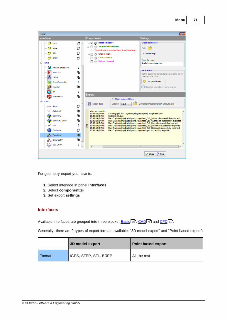
71Menu
© CFturbo Software & Engineering GmbH
For geometry export you have to:
1. Select interface in panel Interfaces
2. Select component(s)
3. Set export settings
Interfaces
Available interfaces are grouped into three blocks: Basic , CAD and CFD .
Generally, there are 2 types of export formats available: "3D model export" and "Point based export":
3D model export Point based export
Format IGES, STEP, STL, BREP All the rest
75 78 81
72 CFturbo 9.2
© CFturbo Software & Engineering GmbH
Content all visible parts in the CFturbo 3Dviewer
predefined set of points/splines(independent from the CFturbo 3D viewer)
Point density variable 1) variable 2)
Units [mm] variable 2)
1) Point density can be configured in the Model settings/ 3D model of each component (Impeller, Stator , Volute ).
2) Point density and export unit can be configured in the Model settings/ Point export of eachcomponent (Impeller , Stator , Volute ).If the blade shape is ruled surface than points of mean lines as well as profiles (pressure andsuction side) are not effected by the model settings for the point based export.
Please note: The results of surface-based operations, e.g. fillets, cannot be exported to point-basedformats.
Remarks about the 3D model export
It is recommended to export solids or solid faces if they are available, because then the individualfaces best fit to each other. Particularly, this is the only sensible option, after 'solid trimming' wasdone during Model finishing .
Components
The list contains all components of the project. If the interface supports multi-component export thenyou can select multiple components, otherwise only a single one.
Some of the interfaces support special component types only, e.g impellers. Therefore some of thecomponents could be deactivated.
Settings
This area contains all available settings for the selected export interface, like export destination andthe base name of exported files. Additional parameters can be available depending on the selectedinterface.
Export
288
310 349
288 310 349
234
288
290
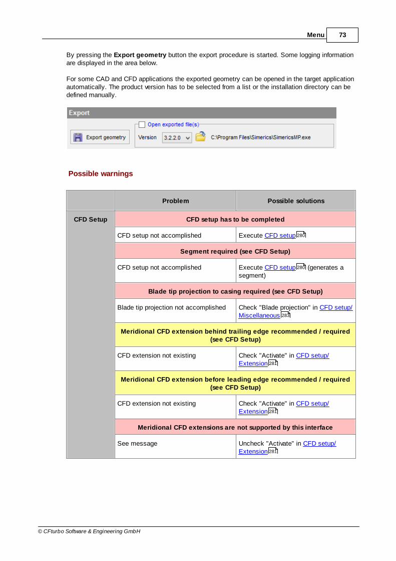
73Menu
© CFturbo Software & Engineering GmbH
By pressing the Export geometry button the export procedure is started. Some logging informationare displayed in the area below.
For some CAD and CFD applications the exported geometry can be opened in the target applicationautomatically. The product version has to be selected from a list or the installation directory can bedefined manually.
Possible warnings
Problem Possible solutions
CFD Setup CFD setup has to be completed
CFD setup not accomplished Execute CFD setup
Segment required (see CFD Setup)
CFD setup not accomplished Execute CFD setup (generates asegment)
Blade tip projection to casing required (see CFD Setup)
Blade tip projection not accomplished Check "Blade projection" in CFD setup/Miscellaneous
Meridional CFD extension behind trailing edge recommended / required(see CFD Setup)
CFD extension not existing Check "Activate" in CFD setup/Extension
Meridional CFD extension before leading edge recommended / required(see CFD Setup)
CFD extension not existing Check "Activate" in CFD setup/Extension
Meridional CFD extensions are not supported by this interface
See message Uncheck "Activate" in CFD setup/Extension
280
280
283
281
281
281
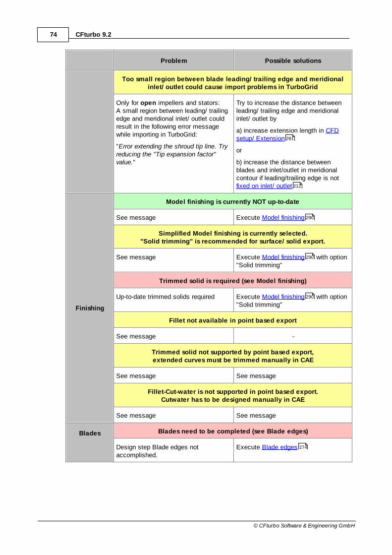
74 CFturbo 9.2
© CFturbo Software & Engineering GmbH
Problem Possible solutions
Too small region between blade leading/ trailing edge and meridionalinlet/ outlet could cause import problems in TurboGrid
Only for open impellers and stators: A small region between leading/ trailingedge and meridional inlet/ outlet couldresult in the following error messagewhile importing in TurboGrid:
"Error extending the shroud tip line. Tryreducing the "Tip expansion factor"value."
Try to increase the distance betweenleading/ trailing edge and meridionalinlet/ outlet by
a) increase extension length in CFDsetup/ Extension
or
b) increase the distance betweenblades and inlet/outlet in meridionalcontour if leading/trailing edge is not fixed on inlet/ outlet
Finishing
Model finishing is currently NOT up-to-date
See message Execute Model finishing
Simplified Model finishing is currently selected."Solid trimming" is recommended for surface/ solid export.
See message Execute Model finishing with option"Solid trimming"
Trimmed solid is required (see Model finishing)
Up-to-date trimmed solids required Execute Model finishing with option"Solid trimming"
Fillet not available in point based export
See message -
Trimmed solid not supported by point based export,extended curves must be trimmed manually in CAE
See message See message
Fillet-Cut-water is not supported in point based export.Cutwater has to be designed manually in CAE
See message See message
Blades Blades need to be completed (see Blade edges)
Design step Blade edges notaccomplished.
Execute Blade edges
281
212
290
290
290
274

75Menu
© CFturbo Software & Engineering GmbH
Problem Possible solutions
Blades are required (see Main dimensions)
Components without blades are nosupported by this interface
-
General All design steps have to be completed before export
Only for CFD-Applications. One or moredesign steps were not finished.
Complete all design steps
Interface does not support tip clearance
Only for ANSYS-BladeGen -
Special license for this interface required
License for this interface not found Check the license information in Preferences/Licensing
No license available, component cannot be exported
The corresponding module is notlicensed or CFturbo is running with atrial license
Only designs corresponding withlicensed modules or unmodified defaultexamples using a trial license can beexported
Parts of an inactive component are visible in the 3D Model. They will notbe exported
See message -
Maximum allowed coordinate values for export exceeded,please choose another export unit (see Model settings)
See message Change length unit in Model settings/Point export
Parts to be exported have to be visible in the 3D Model.Imports can only be exported via the context menu of the 3D Model tree
See message Make all parts to be exported visible inthe component tree
6.2.1.4.1 Basic
? Project | Export | Basic
124
288
157
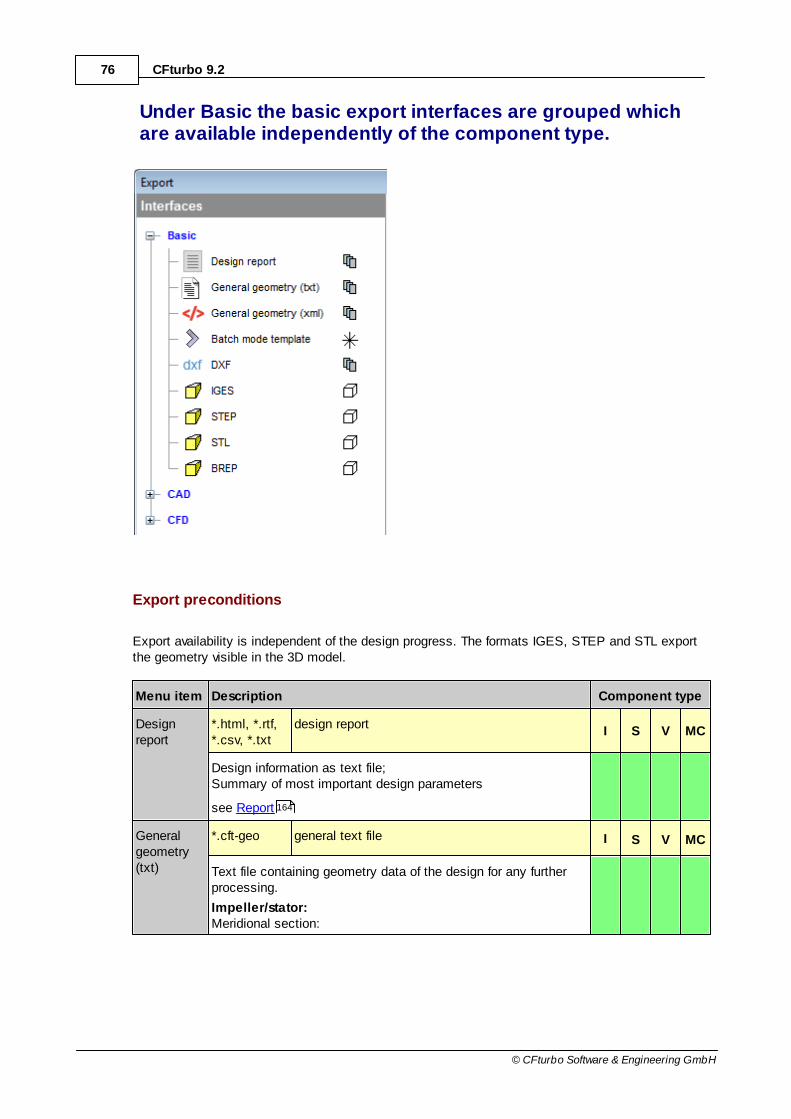
76 CFturbo 9.2
© CFturbo Software & Engineering GmbH
Under Basic the basic export interfaces are grouped whichare available independently of the component type.
Export preconditions
Export availability is independent of the design progress. The formats IGES, STEP and STL exportthe geometry visible in the 3D model.
Menu item Description Component type
Designreport
*.html, *.rtf, *.csv, *.txt
design reportI S V MC
Design information as text file;Summary of most important design parameters
see Report
Generalgeometry(txt)
*.cft-geo general text file I S V MC
Text file containing geometry data of the design for any furtherprocessing.
Impeller/stator:Meridional section:
164

77Menu
© CFturbo Software & Engineering GmbH
z, r of hub, shroud, leading edgeBlade mean lines, Blade profiles:
x, y, z: cartesian coordinatesr: radiust: angleT: tangential lengthm: meridional radius based lengthm/m
TE: meridional radius based length (0..1)
M: meridional absolute lengthM/M
TE: meridional absolute length (0..1)
β: blade angles: blade thicknessL: 3D lengthla: lean angle
Volute:Spiral cross sections, Diffuser cross sections:
x, y, z (cartesian coordinates)Contour lines in circumferential direction:
x, y (cartesian coordinates)
Generalgeometry(xml)
*.cft-geo-xml general xml file I S V MC
XML file containing geometry data of the design for any furtherprocessing.
Batch modetemplate
*.cft-batch XML format file
File is created forwhole project
It contains all changeable values with a short description andsample actions.
see Batch mode
DXF *.dxf neutral format(Drawing Interchange File Format)
I S V MC
File contains designed geometry of the selected component as3D polylines.
IGES *.igs neutral format(Initial Graphics Exchange Specification)
Components andelements are
selected in 3D view
File contains designed geometry as 3D surfaces. Visible 3D viewis the basis.
STEP *.stp neutral format(Standard for the Exchange of Product model data)
File contains designed geometry as 3D surfaces. Visible 3D viewis the basis. Also, the names displayed in the model tree areexported.
STL *.stl neutral format
25

78 CFturbo 9.2
© CFturbo Software & Engineering GmbH
(Standard Triangulation Language)
File contains designed geometry as triangulated 3D surfaces.Some parameters can be adapted. Visible 3D view is thebasis.
BREP *.brep native format of Open Cascade based applications(Boundary Representation)
File contains designedgeometry as 3D surfaces.Visible 3D view is thebasis.
I = Impeller export supportedS = Stator export supportedV = Volute export supportedMC = Multi-Component export supported
6.2.1.4.2 CAD
? Project | Export | CAD
The CAD group contains the supported CAD product interfaces.
114
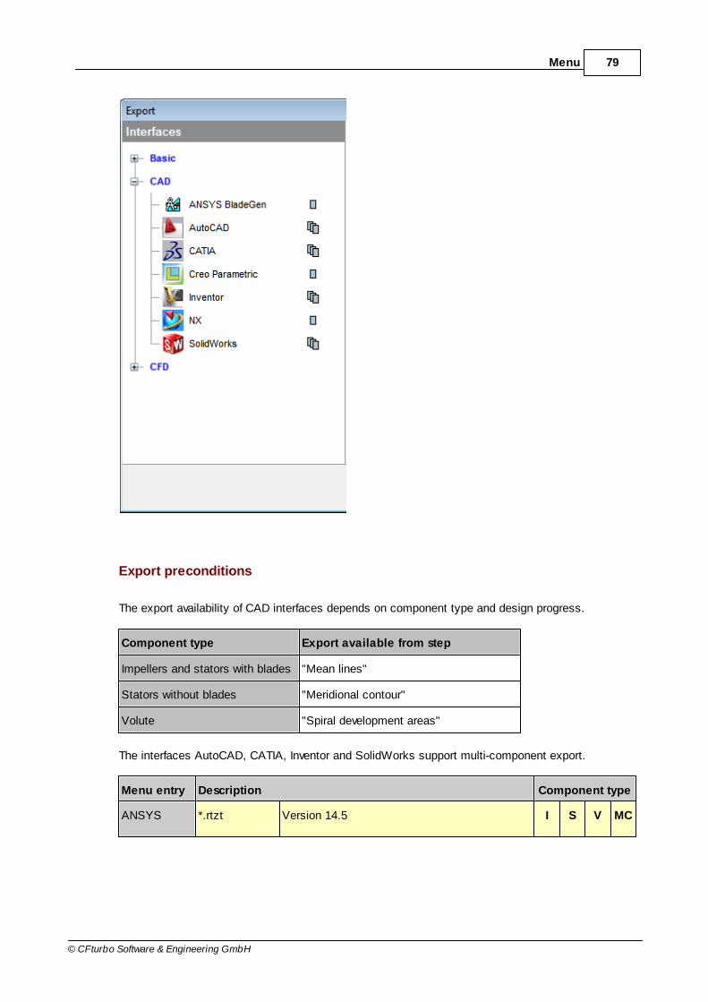
79Menu
© CFturbo Software & Engineering GmbH
Export preconditions
The export availability of CAD interfaces depends on component type and design progress.
Component type Export available from step
Impellers and stators with blades "Mean lines"
Stators without blades "Meridional contour"
Volute "Spiral development areas"
The interfaces AutoCAD, CATIA, Inventor and SolidWorks support multi-component export.
Menu entry Description Component type
ANSYS *.rtzt Version 14.5 I S V MC

80 CFturbo 9.2
© CFturbo Software & Engineering GmbH
BladeGen The file contains complete 3D impeller geometry point-by-point.
File | Open: select file type „Meanline File (*.rtzt)“select *.rtzt file
AutoCAD *-.txt Version 2014 I S V MC
Lisp script xyz2spline (part of CFturbo) creates splines fromimported points.
Select "AutoCAD Classic" WorkspaceLoad "xyz2spline.lsp" under Tools | Load ApplicationRun command "xyz2spline" and select *.txt file
Catia V5 *.catvbs Version V5R19 I S V MC
The macro generates a surface model + generating splines.
Tools | Macro | MacrosSelect macro library and macro, Run
Inventor *.bas Version 2014 I S V MC
The macro generates a surface model + generating splines.
Tools | Visual Basic EditorVB
o File | New project
o File | Import file, select *.bas
o Tools | Macro, select “Main”, Run
CreoParametric
*.ibl, *.pts Version 2.0 M090 I S V MC
*.ibl contains geometry defined by 3D points.
*.pts files are exported for impellers only and contain informationabout blade thickness defined by 2D points
Home | New | Part <name> (if no file is open)Model | Get data | Importselect *.ibl or *.pts file
SolidWorks *.swb Version 2014 I S V MC
The macro generates a surface model + generating splines.
Tools | Macro | Run: select *.swb
NX *-ug.dat Version 8.0 I S V MC
One file per component will be created.
New | New Project file <name> (if no file is open)
To import curves (hub, shroud, volute contour curves):
Insert | Curve | Spline | Through pointsPoints from fileselect *.dat file
To generate surfaces (blade, volute, diffuser):

81Menu
© CFturbo Software & Engineering GmbH
Insert | surface | Through pointsRow degree <= number of blade profile sectionsColumn degree <= Row degree-1Points from fileselect *.dat file
Please note: If the mentioned menu options are not available,the appropriate commands have to be created:
a) "Tools/Customize" or right click on any toolbar/menu,"Customize..."
b) "Commands", "Insert/Curve/Spline..." or "Insert/Surface/Through Points..."
c) Integrate selected item via Drag and Drop in a menu or toolbar
I = Impeller export supportedS = Stator export supportedV = Volute export supportedMC = Multi-Component export supported
6.2.1.4.3 CFD
? Project | Export | CFD
The CFD group contains the supported CFD product interfaces.
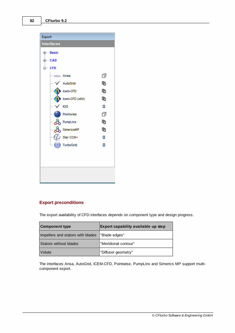
82 CFturbo 9.2
© CFturbo Software & Engineering GmbH
Export preconditions
The export availability of CFD interfaces depends on component type and design progress.
Component type Export capability available up step
Impellers and stators with blades "Blade edges"
Stators without blades "Meridional contour"
Volute "Diffuser geometry"
The interfaces Ansa, AutoGrid, ICEM-CFD, Pointwise, PumpLinx and Simerics MP support multi-component export.

83Menu
© CFturbo Software & Engineering GmbH
Menu entry Description Component type
Ansa *.igs Version 15.0 I S V MC
File | OpenSelect *.igs file
NumecaAutogrid
*.geomTurbo Version 9.0 I S V MC
File | New Project“Initialize a New Project from a geomTurbo File”Select *.geomTurbo file
ANSYS ICEM-CFD
*.tinXML, *.stp Version 12, 13, 14, 14.5 I S V MC
A STEP file with named geometries is created. The names arevisible in ICEM if the file is imported via Workbench Reader.
Parameters are saved in a separate XML file.
Numeca IGG *.dst, *.dat Version 8.10-2 I S V MC
A model file *.dst and 3 data files are generated: section.dat,diffusor.dat, curves.dat
File | Import | IGG DataSelect *.dst file
Pointwise *.igs Version 17.0R2 I S V MC
File | Import | DatabaseSelect *.igs file
Simerics MPPumpLinx
*.spro, *.stl Version 3.2.2 I S V MC
The *.spro file contains all project information. The *.stl filecontains the geometry in STL format as triangulated 3Dsurfaces. Some parameters can be adapted.
In Simerics MP/ PumpLinx: Select *.spro file under Open project
CD-adapcoStar-CCM+
*.bndy, *.estg, *.trbw Version 8.04.007 I S V MC
Mesh | Import turbo blades...Select *.trbw file under Load Turbo Wizard Settings
ANSYSTurboGrid
*.curve Version 14.5 I S V MC
4 files are created, a session file (<filename>.tse) and<filename>_hub.curve, <filename>_shroud.curve,<filename>_profile.curve.
Load the saved session file <filename>.tse:
File | New CaseSession | Play Session
or
114

84 CFturbo 9.2
© CFturbo Software & Engineering GmbH
Open the curve files (<filename>_hub.curve, <filename>_shroud.curve, <filename>_profile.curve) manually:
Launcher: select directory, start ANSYS TGFile | New CaseFile | Load Curvesinput number of blades, define z axis as rotational axis,select cartesian coordinate system and length unit, select *.curve file
I = Impeller export supportedS = Stator export supportedV = Volute export supportedMC = Multi-Component export supported
ANSYS ICEM-CFD
This interface is supporting the script solution CFturbo2ICEM for automated meshing of CFturbogeometries. Detailed information can be found on the CFturbo website.
The button Set parameters... opens the Export ICEM-CFD dialog for defining meshingparameters. These settings are saved in the *.tinXML file, whereas the geometry is transferred by a*.stp file.
For more information about using CFturbo2ICEM please see the available documentation.
6.2.1.4.4 Specif ics
The following topics contain specific information about how to import the geometry designed byCFturbo into some CAE applications:
Autodesk AutoCAD
Autodesk Inventor
Catia (Dassault Systèmes)
Numeca AutoGrid
Creo Parametric (PTC)
ANSYS ICEM-CFD
STL
112
85
91
94
94
96
112
114

85Menu
© CFturbo Software & Engineering GmbH
6.2.1.4.4.1 Autodesk AutoCAD
The data import from CFturbo is realized by a LISP-script.
Loading the LISP-Application and Import of the Geometry
Select "AutoCAD Classic" Workspace
Tools | Load Application (command: _appload)
Select file "xyz2spline.lsp" from CFturbo-installation directory, load and close dialog
Execute loaded LISP-application by command xyz2spline
Select and open *.txt file exported from CFturbo
Attention: If "; Error: Bad argument type: FILE nil" occurs as error message it can be bypassed bytyping the filename in the open-file-dialog manually instead of selecting the file by mouse click.

86 CFturbo 9.2
© CFturbo Software & Engineering GmbH
Selection of xyz2spline.lsp file
Construction of Impeller
Creating the blades
Use the command _loft to create surfaces from curves
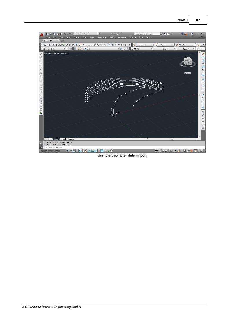
87Menu
© CFturbo Software & Engineering GmbH
Sample-view after data import
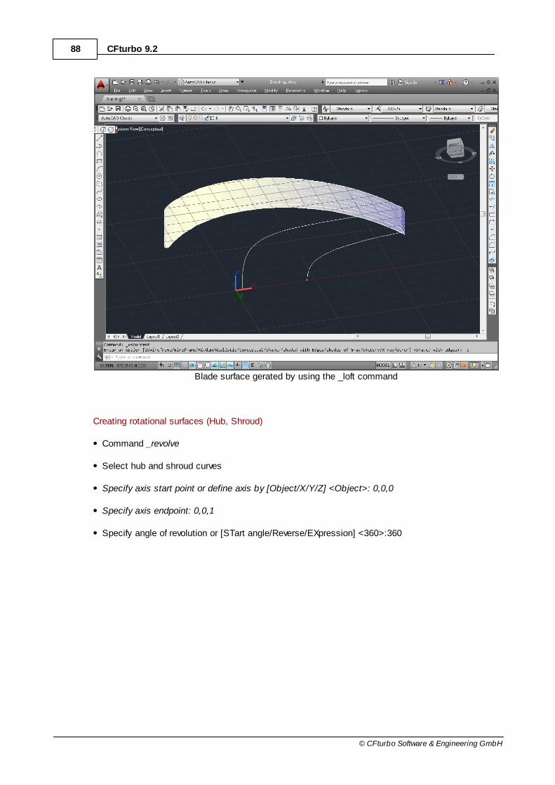
88 CFturbo 9.2
© CFturbo Software & Engineering GmbH
Blade surface gerated by using the _loft command
Creating rotational surfaces (Hub, Shroud)
Command _revolve
Select hub and shroud curves
Specify axis start point or define axis by [Object/X/Y/Z] <Object>: 0,0,0
Specify axis endpoint: 0,0,1
Specify angle of revolution or [STart angle/Reverse/EXpression] <360>:360

89Menu
© CFturbo Software & Engineering GmbH
Hub and Shroud surfaces
Construction of Volute
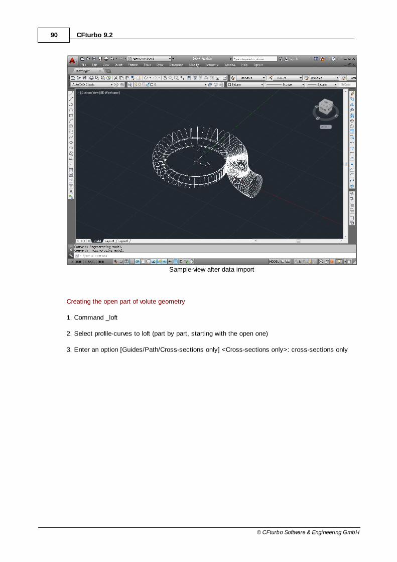
90 CFturbo 9.2
© CFturbo Software & Engineering GmbH
Sample-view after data import
Creating the open part of volute geometry
1. Command _loft
2. Select profile-curves to loft (part by part, starting with the open one)
3. Enter an option [Guides/Path/Cross-sections only] <Cross-sections only>: cross-sections only

91Menu
© CFturbo Software & Engineering GmbH
Settings for lofted surface
4. Repeat steps 1 to 4 for remaining parts of the volute
6.2.1.4.4.2 Autodesk Inventor
The data-import is realized by a macro that is created for each geometry individually by CFturbo. Themacro is loaded and executed in Inventor.
To execute a macro it has to be imported into an existing VBA-project.
Tools | VBA Editor
Open file-open-dialog by File | Import File... and select *.bas macro-file, possibly a new projecthas to be created File | New Project

92 CFturbo 9.2
© CFturbo Software & Engineering GmbH
Execute imported macro: Run | Run Macro (F5) close dialog by Run

93Menu
© CFturbo Software & Engineering GmbH
The time for executing depends on the complexity of the geometry.
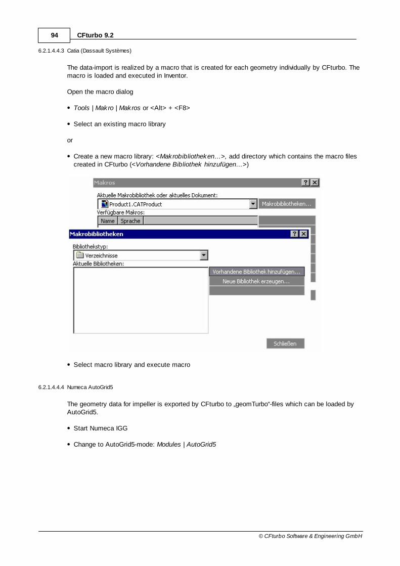
94 CFturbo 9.2
© CFturbo Software & Engineering GmbH
6.2.1.4.4.3 Catia (Dassault Systèmes)
The data-import is realized by a macro that is created for each geometry individually by CFturbo. Themacro is loaded and executed in Inventor.
Open the macro dialog
Tools | Makro | Makros or <Alt> + <F8>
Select an existing macro library
or
Create a new macro library: <Makrobibliotheken…>, add directory which contains the macro filescreated in CFturbo (<Vorhandene Bibliothek hinzufügen…>)
Select macro library and execute macro
6.2.1.4.4.4 Numeca AutoGrid5
The geometry data for impeller is exported by CFturbo to „geomTurbo“-files which can be loaded byAutoGrid5.
Start Numeca IGG
Change to AutoGrid5-mode: Modules | AutoGrid5

95Menu
© CFturbo Software & Engineering GmbH
Open a new project: File | New Project
Close dialog by Initialize a New Project from a geomTurbo File

96 CFturbo 9.2
© CFturbo Software & Engineering GmbH
Select *.geomTurbo-file
For unshrouded impellers the tip clearance has to be applied in AutoGrid manually.
6.2.1.4.4.5 Creo Parametric (PTC)
The following files are exported by CFturbo for impellers:
*-hub.ibl, *-shroud.ibl: points of hub and shroud
*-profile.ibl: points for blade profiles
*.ibl: all points for hub, shroud and blades
The following files are exported by CFturbo for volutes:
*-contour-line.ibl: spiral contour points
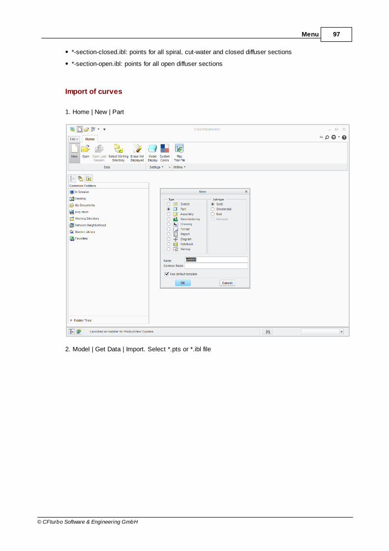
97Menu
© CFturbo Software & Engineering GmbH
*-section-closed.ibl: points for all spiral, cut-water and closed diffuser sections
*-section-open.ibl: points for all open diffuser sections
Import of curves
1. Home | New | Part
2. Model | Get Data | Import. Select *.pts or *.ibl file

98 CFturbo 9.2
© CFturbo Software & Engineering GmbH
3. In "File" dialog, select desired import options
4. Confirm to finish import process

99Menu
© CFturbo Software & Engineering GmbH
All curves can be imported in this way

100 CFturbo 9.2
© CFturbo Software & Engineering GmbH
Creating revolution surfaces
1. Model | Datum | Axis: create axis of revolution selecting the two proper datum planes. (Note: useCtrl for multi-selection)
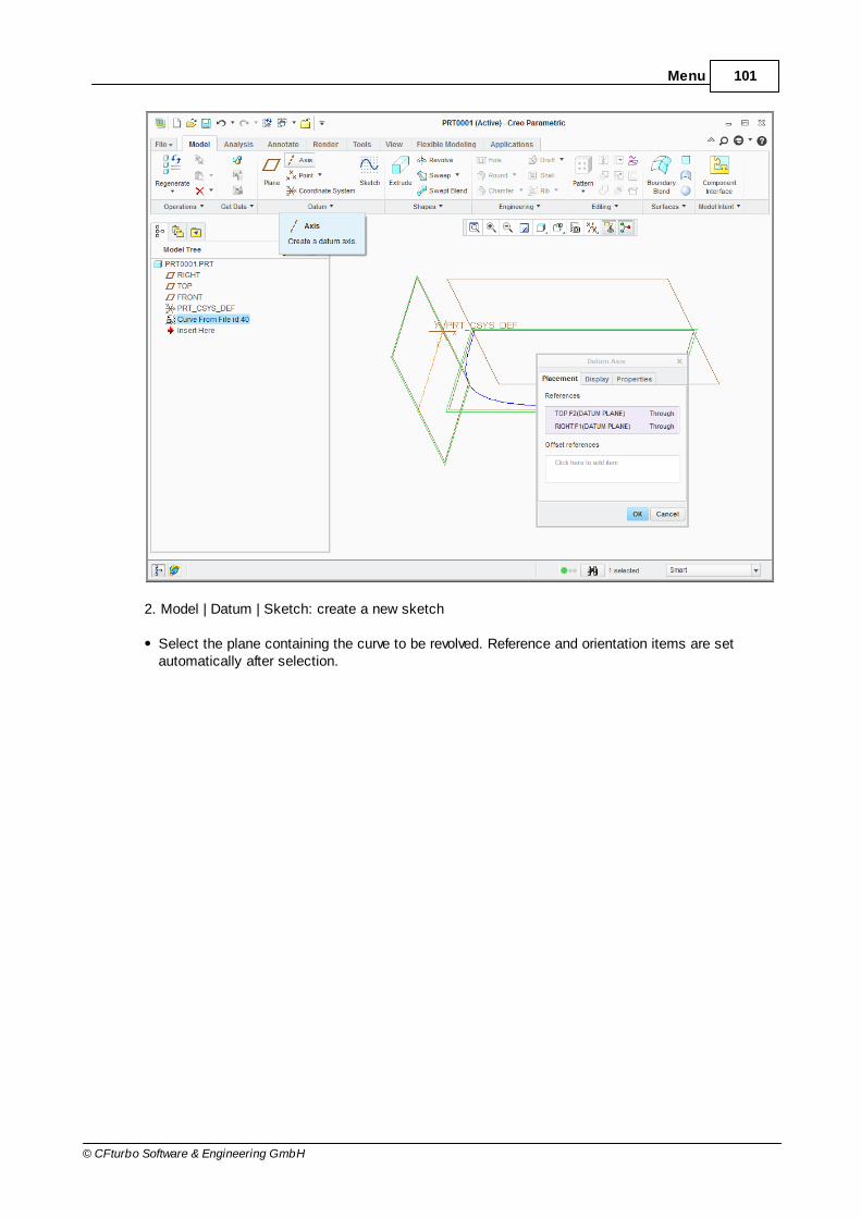
101Menu
© CFturbo Software & Engineering GmbH
2. Model | Datum | Sketch: create a new sketch
Select the plane containing the curve to be revolved. Reference and orientation items are setautomatically after selection.

102 CFturbo 9.2
© CFturbo Software & Engineering GmbH
Sketch | Sketching | Project: do a projection of the curve selecting the curve. Select option"Single" and click on "Close"
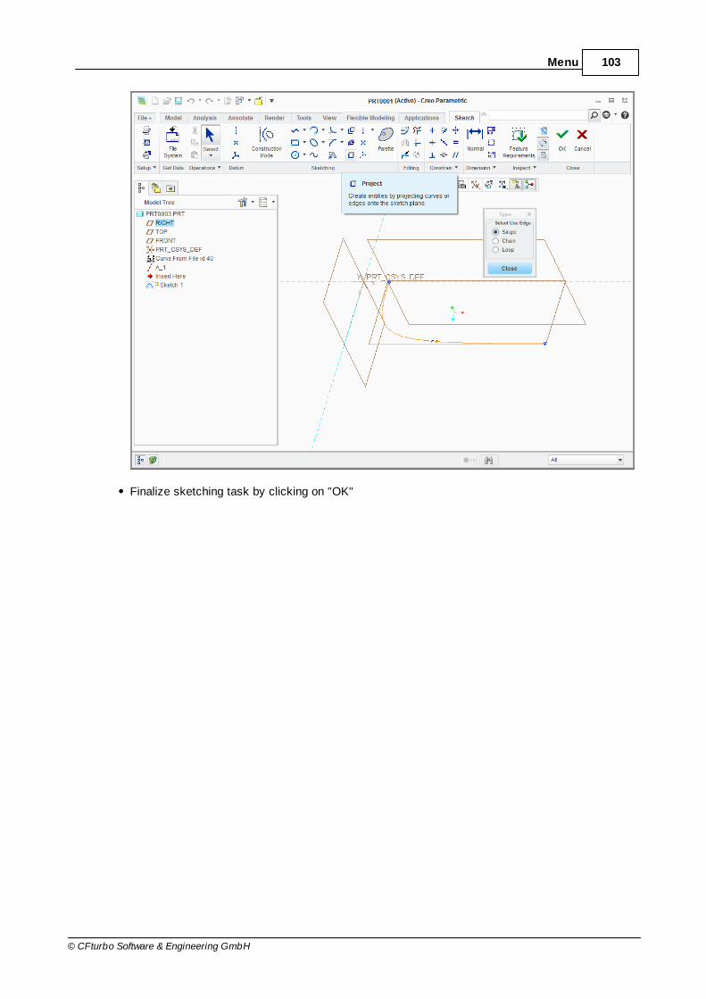
103Menu
© CFturbo Software & Engineering GmbH
Finalize sketching task by clicking on "OK"

104 CFturbo 9.2
© CFturbo Software & Engineering GmbH
3. Select the curve and click on Model | Shapes | Revolve
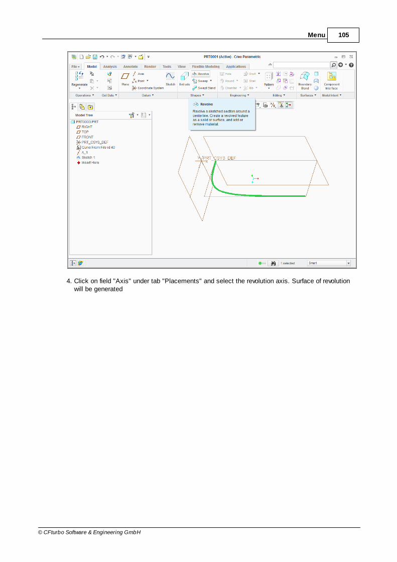
105Menu
© CFturbo Software & Engineering GmbH
4. Click on field "Axis" under tab "Placements" and select the revolution axis. Surface of revolutionwill be generated

106 CFturbo 9.2
© CFturbo Software & Engineering GmbH

107Menu
© CFturbo Software & Engineering GmbH
5. Finalize revolve task by clicking on "OK"

108 CFturbo 9.2
© CFturbo Software & Engineering GmbH
Creating lofted surfaces
Lofted surfaces are created from blade profiles and spiral section curves.
1. Model | Surface | Boundary Blend
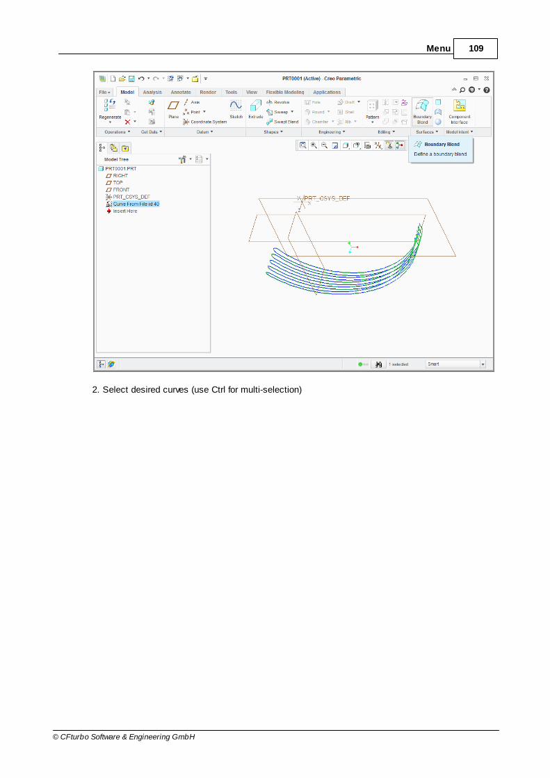
109Menu
© CFturbo Software & Engineering GmbH
2. Select desired curves (use Ctrl for multi-selection)
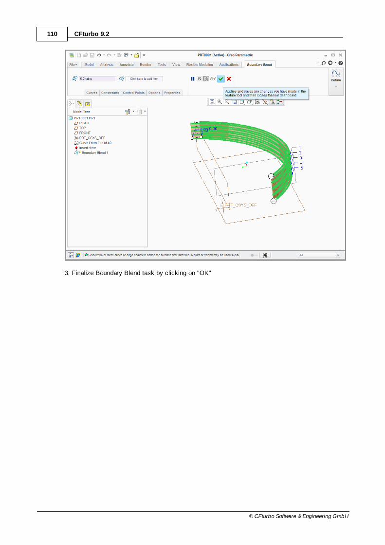
110 CFturbo 9.2
© CFturbo Software & Engineering GmbH
3. Finalize Boundary Blend task by clicking on "OK"

111Menu
© CFturbo Software & Engineering GmbH
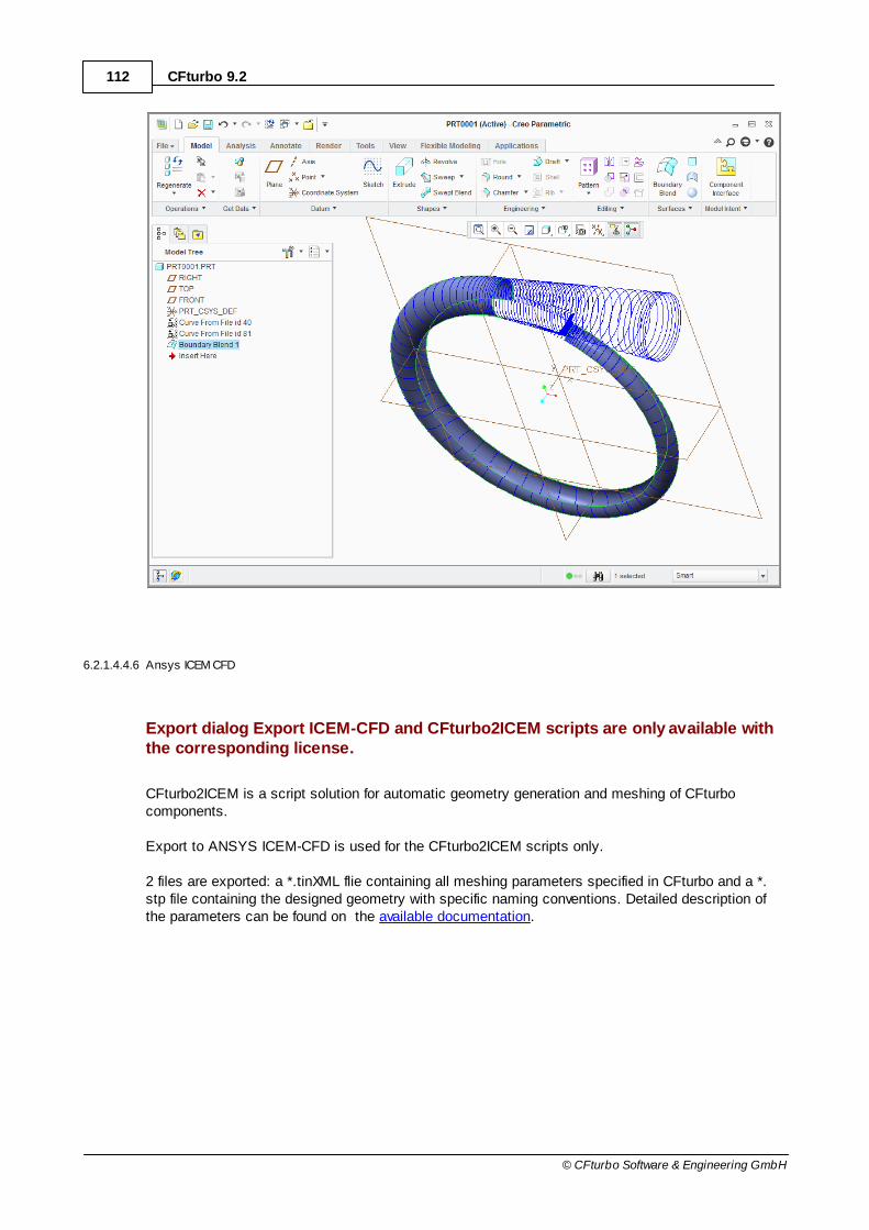
112 CFturbo 9.2
© CFturbo Software & Engineering GmbH
6.2.1.4.4.6 Ansys ICEM CFD
Export dialog Export ICEM-CFD and CFturbo2ICEM scripts are only available withthe corresponding license.
CFturbo2ICEM is a script solution for automatic geometry generation and meshing of CFturbocomponents.
Export to ANSYS ICEM-CFD is used for the CFturbo2ICEM scripts only.
2 files are exported: a *.tinXML flie containing all meshing parameters specified in CFturbo and a *.stp file containing the designed geometry with specific naming conventions. Detailed description ofthe parameters can be found on the available documentation.
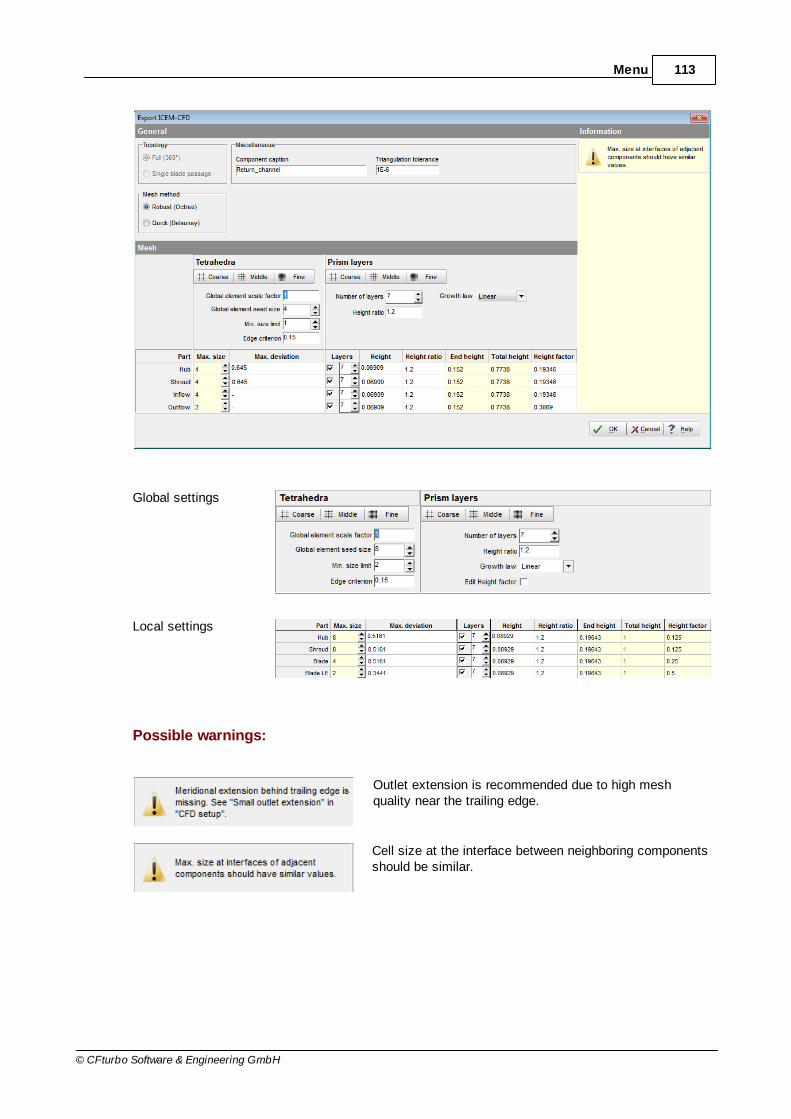
113Menu
© CFturbo Software & Engineering GmbH
Global settings
Local settings
Possible warnings:
Outlet extension is recommended due to high meshquality near the trailing edge.
Cell size at the interface between neighboring componentsshould be similar.
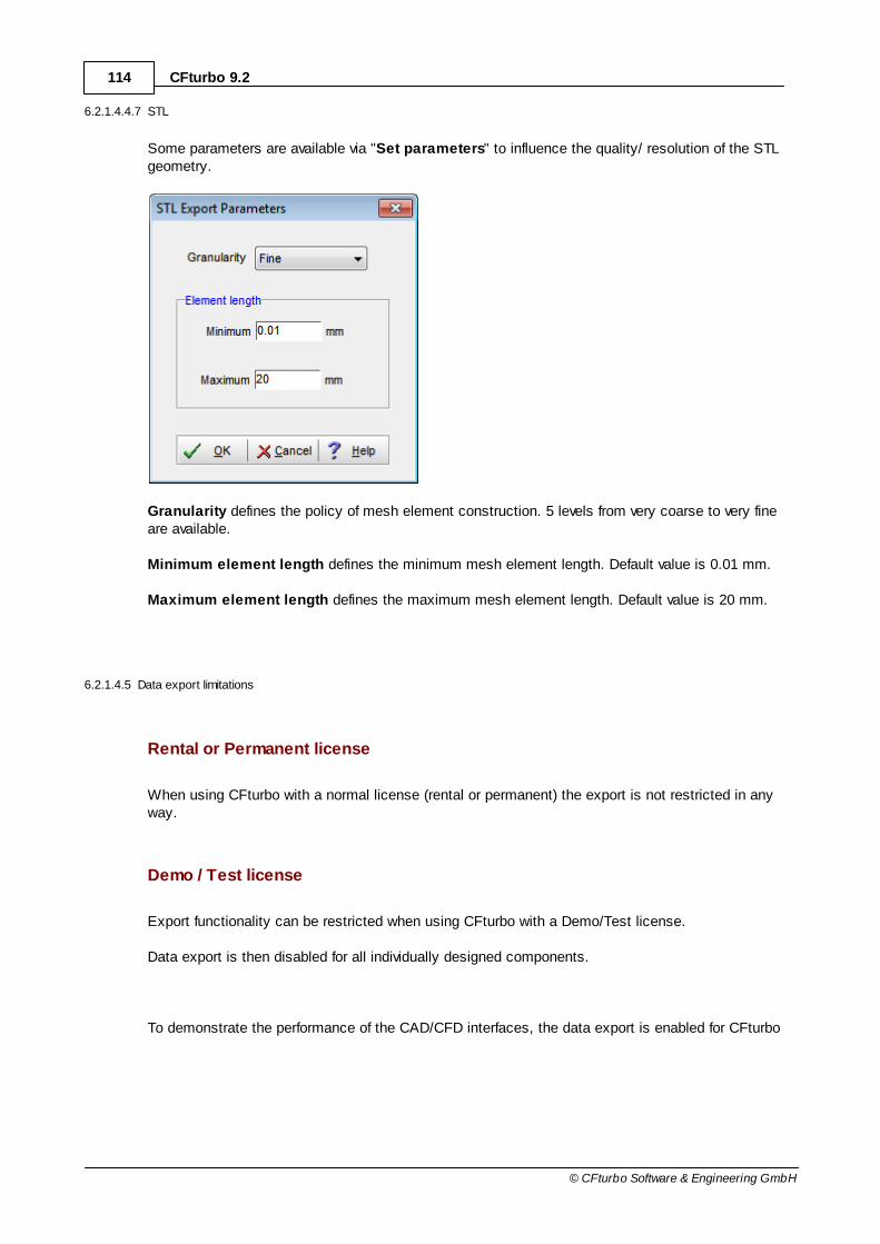
114 CFturbo 9.2
© CFturbo Software & Engineering GmbH
6.2.1.4.4.7 STL
Some parameters are available via "Set parameters" to influence the quality/ resolution of the STLgeometry.
Granularity defines the policy of mesh element construction. 5 levels from very coarse to very fineare available.
Minimum element length defines the minimum mesh element length. Default value is 0.01 mm.
Maximum element length defines the maximum mesh element length. Default value is 20 mm.
6.2.1.4.5 Data export limitations
Rental or Permanent license
When using CFturbo with a normal license (rental or permanent) the export is not restricted in anyway.
Demo / Test license
Export functionality can be restricted when using CFturbo with a Demo/Test license.
Data export is then disabled for all individually designed components.
To demonstrate the performance of the CAD/CFD interfaces, the data export is enabled for CFturbo

115Menu
© CFturbo Software & Engineering GmbH
default examples only.
These default examples you can find
(1) in the CFturbo installation directory: in the directory Examples
(2) on the CFturbo website: http://www.cfturbo.com/download.html
6.2.1.5 Import 3D geometry
? Project | Project | Import 3D
The 3D Import enables the user to view 3D data in IGES, STEP, STL and BREP format or ofCFturbo-projects (*.cft) e.g. for comparison with the current design. Geometry data is shown in the 3D Model and can be transformed and exported.
Imported CFturbo-projects are a pure 3D data import. The structure of geometrical parts is visible inthe 3D model tree , but no design steps can be modified.
If the the import consumes a lot of time, a lower resolution can be selected (see also Model display).
6.2.1.6 Reference components
? Project | Project | Reference components
This functionality can be used for simultaneous display of various designs to compare each otherand for purposeful modification.
150 158
157
151
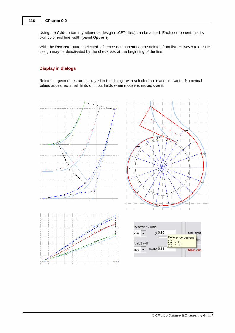
116 CFturbo 9.2
© CFturbo Software & Engineering GmbH
Using the Add-button any reference design (*.CFT- files) can be added. Each component has itsown color and line width (panel Options).
With the Remove-button selected reference component can be deleted from list. However referencedesign may be deactivated by the check box at the beginning of the line.
Display in dialogs
Reference geometries are displayed in the dialogs with selected color and line width. Numericalvalues appear as small hints on input fields when mouse is moved over it.
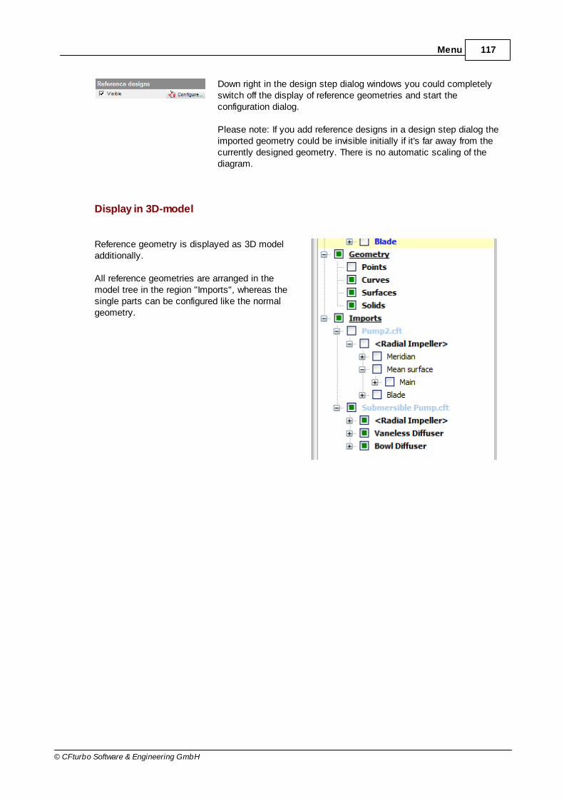
117Menu
© CFturbo Software & Engineering GmbH
Down right in the design step dialog windows you could completelyswitch off the display of reference geometries and start theconfiguration dialog.
Please note: If you add reference designs in a design step dialog theimported geometry could be invisible initially if it's far away from thecurrently designed geometry. There is no automatic scaling of thediagram.
Display in 3D-model
Reference geometry is displayed as 3D modeladditionally.
All reference geometries are arranged in themodel tree in the region "Imports", whereas thesingle parts can be configured like the normalgeometry.

118 CFturbo 9.2
© CFturbo Software & Engineering GmbH
6.2.1.7 Show/Hide messages
? Project | Project | Show/ Hide messages
This button shows or hides the message panel on the right side of the main window.
More information to the message panel are available in the Opened project section.
6.2.1.8 Undo
? Project | Project | Undo
The design history can be opened by clicking the undo-button. It contains all modifications fromopening of the project or session in chronological order. By selecting a list entry, this design stepand all following ones are removed. Prior to that you can save the current design optionally.
46

119Menu
© CFturbo Software & Engineering GmbH
The undo-button is also placed in the quick access bar by default.
6.2.2 Selected component
? Project | Selected Component
All operations in this group refer to the currently selected component.
Add component
Active/ Rename/ Delete
Remove design steps
6.2.2.1 Add component
? Project | Selected Component | Add component
A new component can be inserted before or behind the currently selected one, followed by selectingthe type or adding a existing one from another project.
119
120
122

120 CFturbo 9.2
© CFturbo Software & Engineering GmbH
There can be only a single impeller and and single volute in a project.
Please note: If you add a component on the first position of the project (in flow direction) then the inlet conditionsdefined in the Global setup are applied for this new component.
6.2.2.2 Active/ Rename/ Delete
The actions Active, Rename and Delete can be executed in the following manner alternatively:
Menu Project | Selected Component
Context menu of the corresponding component left in panel Components
Context menu of the corresponding component right in the meridional preview
? Project | Selected Component | Active
By activating or deactivating the checkbox, the state of a component can be changed from active toinactive. An inactive one is read only and also not going to be updated automatically. They arecolored grey in all views when inactive.
58

121Menu
© CFturbo Software & Engineering GmbH
? Project | Selected Component | Rename
Change the caption of a component. The caption is displayed left in the components list as hintwhen moving the mouse cursor on the icon and in the meridional view.
? Project | Selected Component | Delete
The selected component is going to be deleted after confirming the warning.

122 CFturbo 9.2
© CFturbo Software & Engineering GmbH
6.2.2.3 Remove design steps
? Project | Selected Component | Remove design steps
If you make any design modifications on the current component then all following design steps areadapted automatically (parametric model).
However, if you would like to start with an automatic generated CFturbo initial design, certain designsteps can be removed manually. Then CFturbo continues with new initial design data. For thatpurpose you have to select the appropriate design step to be removed and then press the OK-button.
Of course, all following design steps after the selected one are removed too.

123Menu
© CFturbo Software & Engineering GmbH
6.3 Impeller/ Stator/ Volute
These menus are used for the actual component design.
A separate tab with the corresponding design steps is available for each component type:
Impeller
Stator
Volute
Menu items and buttons only become active in accordance to the current design state. Eachfinished design steps can be opened again whereas all depending design steps and components areupdated automatically. Manual removing of complete component's design steps is possible in order
to continue with CFturbo® initial design (see Remove design steps ).
For designing the complete geometry of a single component you have to run through all items of theappropriate menu step by step.
6.4 Preferences
Menu Preferences is used for specifying some general program settings:
Licensing
166
296
312
122
124

124 CFturbo 9.2
© CFturbo Software & Engineering GmbH
Approximation functions
Fluids
General
Units
Impeller/ Stator
6.4.1 Licensing
? Perferences | Licensing | Licensing
See General/ Licensing
6.4.2 Approximation functions
? Perferences | Database | Approximation functions
CFturbo uses many approximation functions. These functions are based on published measurementdata that facilitate the forecast of optimal or accessible values.
In this dialog the approximation functions are displayed graphically and can be customized. If anopen project is available then only the project relevant functions are displayed, otherwise allfunctions are available.
Functions for the following physical quantities are available:
Impeller
Diameter coefficient
Pump, Ventilator impeller
Width number b2/d
2
Flow angle inflow 0A
Flow angle outflow 3
Volumetric efficiency V
Tip clearance efficiency T
Side friction efficiency S
Mechanical efficiency m
124
129
132
135
139
11
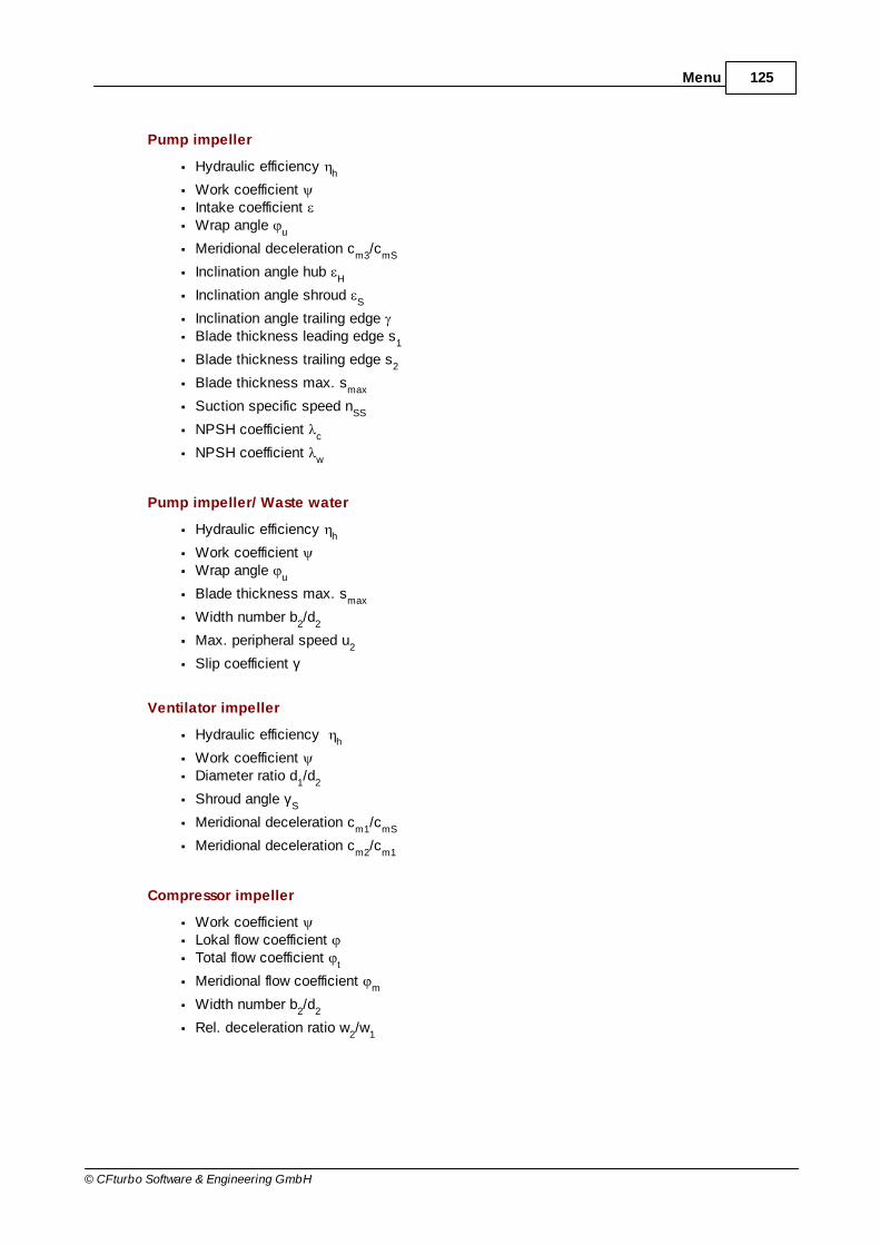
125Menu
© CFturbo Software & Engineering GmbH
Pump impeller
Hydraulic efficiency h
Work coefficient Intake coefficient Wrap angle
u
Meridional deceleration cm3
/cmS
Inclination angle hub H
Inclination angle shroud S
Inclination angle trailing edge Blade thickness leading edge s
1
Blade thickness trailing edge s2
Blade thickness max. smax
Suction specific speed nSS
NPSH coefficient c
NPSH coefficient w
Pump impeller/ Waste water
Hydraulic efficiency h
Work coefficient Wrap angle
u
Blade thickness max. smax
Width number b2/d
2
Max. peripheral speed u2
Slip coefficient γ
Ventilator impeller
Hydraulic efficiency h
Work coefficient Diameter ratio d
1/d
2
Shroud angle γS
Meridional deceleration cm1
/cmS
Meridional deceleration cm2
/cm1
Compressor impeller
Work coefficient Lokal flow coefficient Total flow coefficient
t
Meridional flow coefficient m
Width number b2/d
2
Rel. deceleration ratio w2/w
1

126 CFturbo 9.2
© CFturbo Software & Engineering GmbH
Meridional deceleration cm2
/cm1
Meridional deceleration cm1
/cmS
Meridional deceleration cm2
/cmS
Machine Mach number Mu2
Peripheral speed u2
Diameter ratio d1/d
2
Total-to-total efficiency tt
Volumetric efficiency V
Mechanical efficiency m
Rel. inlet flow angle S
Rel. inlet Mach number MwS
Turbine rotor
Meridional flow coefficient m
Tangential force coefficient ct
Coefficient ratio cr
Meridional acceleration cm2
/cm1
Meridional acceleration cmS
/cm2
Wrap angle u
Total-to-total efficiency tt
Total-to-static efficiency ts
Velocity ratio νs
Mechanical efficiency m
Diameter ratio dS/d
1
Diameter ratio d2/d
1
Stators
Axial extension (bowl diffuser) Lax
/d2
Deceleration ratio (radial diffuser) c3q
/c2
Inlet diameter ratio (bowl diffuser) dIn
/d2
Inlet diameter ratio (radial diffuser) dIn
/d2
Inlet width ratio (bowl diffuser) bIn
/b2
Inlet width ratio (radial diffuser) bIn
/b2
Outlet diameter ratio (radial diffuser) dOut
/d2
Oversize factor (radial diffuser) fa3
Volute
Cut-water diameter ratio d4/d
2
Cut-water width ratio b4/b
2

127Menu
© CFturbo Software & Engineering GmbH
Stepanoff constant ks
Each function has a hard coded default function. For each of these functions custom point wisedefined curves can be added alternatively. These custom defined curves are saved in the file Functions.cftfu that contains the custom defined functions only. The default functions are not savedin any external file and cannot be deleted. The default functions can only be deactivated by definingany custom function that is saved in the Functions file.
On the top left at File location, the name of the file is shown that contains all user-definedfunctions. In general this file is called Functions.cftfu, and is located in the installation directory ofCFturbo. Modifications to functions are saved automatically if you leave the dialog window bypressing the OK-button. In case the user has no write permissions one could choose a differentdirectory to save the file. Changing filename and directory is possible by using the Save as-function.By clicking the Open-button a previously saved functions file can be opened.
The link to the functions file is part of each major/minor installation (CFturbo x.y). All updates bybug-fix releases (CFturbo x.y.z) do not modify the link to the existing function file.
The function file will not be overwritten by any update. By default the functions file is located in theCFturbo installation directory. When you define any user-defined functions it’s recommended to savethe functions file not in the CFturbo installation directory but anywhere in the network for tworeasons:
all users can use the same database for their design
there is no risk of losing data by uninstall older versions of CFturbo

128 CFturbo 9.2
© CFturbo Software & Engineering GmbH
All available functions are listed in a tree structure in the panel Functions left from diagram, sortedby machine type.
The user must first select the variable under the corresponding machine type. CFturbo’s internalfunction is displayed in the diagram in blue color. You can add any user defined function for eachvariable. Selected function is displayed in the diagram in addition to CFturbo's internal function.Function with active check box is used by CFturbo for calculations. If no function has activecheckbox or no additional function is defined at all, then the CFturbo internal function is used.
With these buttons below the tree you can add, delete or rename functions.
The following hierarchy exist in the tree:
physical variable
user defined function
parameter curve (available for some functions only)
upper limit curve (optional)
Functions can depend on 2 variables whereas one serves as parameter. Separate curves exist foreach particular parameter value that are used to calculate function values. The parameter value isdisplayed on endpoint of the curve in the diagram.
With the upper limit curve you can define a recommended range, which means an area that isdefined by a higher and a lower limit.
In panel Points right from diagram you can edit curve points of selected function. You can add newpoints at the end of the table – the points are automatically sorted by x values. To remove a pointyou have to delete either x or y value.
These buttons are enabling the user to:
import points from file (one point per line)
export points to file
copy all points to clipboard
paste points from clipboard (e.g from Excel)
clear the table

129Menu
© CFturbo Software & Engineering GmbH
On panel Test you can test the active function. Saving of values is possible by clicking OK-button.
6.4.3 Fluids
? Preferences | Database | Fluids
The dialog lists all defined fluids. New ones can be added, present fluids can be renamed or deleted.

130 CFturbo 9.2
© CFturbo Software & Engineering GmbH
In the right panel, the properties of the selected fluid can be defined. The available parameter varydepending on the medium type (compressible/incompressible).
The buttons for opening and saving offer the possibility of the exchange of fluid data between CFturboinstallations.
Incompressible fluid [ for pumps, ventilators only ]
A constant density ρ is the only parameter.
Compressible fluid [ for compressors, turbines only ]
In this case some gas properties are required because they are used in the gas models for thedescriptions of the behavior of the gases. Those parameters are:
gas constant R
critical pressure pcrit
, temperature Tcrit
and density ρcrit
acentric factor ω
heat capacity cp + heat capacity coefficients c
pi (both at zero pressure)
compressibility factor Z
Currently the following gas models are implemented. They represent a relation between pressure,temperature and density (here given with its reciprocal the spec. volume v):
Gas model Approach Annotation Reference (firstpublished)
Perfect Gasv
ZTRp
Redlich-Kwong
bvv
Ta
cbv
TRp Each approach has its own
set of coefficients a, b and c.
Redlich, O., Kwong, J.N.S.
Aungier/Redlich-Kwong
Aungier, R.H.
Soave/Redlich-Kwong
Soave, G.
355
355
355

131Menu
© CFturbo Software & Engineering GmbH
Peng-Robinson 22 2 bvbv
Ta
cbv
TRp Peng, D.Y., Robinson,
D.B.
The implemented gas property models can be tested with user defined data. Those data consists ofa thermodynamic state defined by p
1 and T
1. Using these values the density ρ
1 and the specific heat
cp will be calculated. Also, using a pressure p
2 the gas shall be compressed or expanded to an
isentropic temperature T2is
will be calculated. A second temperature T2 is calculated under the
assumption that the gas shall be compressed or expanded from state 1 to pressure p2 by an effort or
benefit of an enthalpy difference ±∆h, see h-s-diagram.
355

132 CFturbo 9.2
© CFturbo Software & Engineering GmbH
6.4.4 General
? Preferences | Settings | General
Menu item General preferences is used for global program options.

133Menu
© CFturbo Software & Engineering GmbH
Language of online help
In this dialog the language of online help can be set. The default is English.
Warning before license expiration

134 CFturbo 9.2
© CFturbo Software & Engineering GmbH
Furthermore you can specify thenumber of days for license expirationwarning at startup. Default value is 20days.
The warning message looks asfollows:
Initial view after loading file
Select which view should be displayed after file loading. Choosing the 3D Model will increase thetime needed for loading, because the model gets updated first.
Check for available updates
Optionally, you can check for available updates at program startup. 3 alternative intervals areavailable: at each start, weekly, monthly.
An update check can be started directly using the button "Check now..." (see Check for Updates). The date of last update check is displayed for information.
142

135Menu
© CFturbo Software & Engineering GmbH
Reset "Additional Views" configuration
Deletes the configuration of "Additional Views" of all dialogs. The configuration contains the visibilityas well as width and height of the visible elements.
3D model mouse handling
Here you can assign functions (Rotate, Zoom, Move) to the mouse buttons (Left, Middle, Right) for handling the 3D model .
Action when double-clicking component
The default action for double-clicking on a component in the component list can be set. This enablesthe user to quickly switch to the menu needed.
6.4.5 Units
? Preferences | Settings | Units
Unit settings can be used for selecting the display units in CFturbo.
It's divided in 3 parts:
General : general unit selection
Specific speed : selecting a suitable specific speed definition
Other : some additional unit settings, like flow/blade angle and nss
definition
150
136
136
138

136 CFturbo 9.2
© CFturbo Software & Engineering GmbH
6.4.5.1 General
Here the physical units used in the dialogs can be set. Following units are available:
Head: m, ft
Length: mm, in, m
Volume flow: m3/h, m3/min, m3/s, ft3/h, ft3/s, gpm, gps
Density: kg/m3, lb/ft3
Stress: MPa, PSI
Pressure: MPa, PSI, bar, Pa
Power: kW, hp
Mass flow: kg/s, lb/s
Temperature: °C, K, °F
Area: mm², m², in²
Velocity: m/s, ft/s
Ratio: %, -
Revolutions: /min, /s
You can simultaneously change all units to SI or US system by pressing the buttons above.
6.4.5.2 Specific speed
Here the specific speed definition can be selected. This definition is mainly used for the Approximation functions .
The definitions mainly differ in the units used for rotational speed, flow rate and energy transmission.
124

137Menu
© CFturbo Software & Engineering GmbH
Following definitions are available:
General specific speed nq* (dimensionless)
43
21*
qY
Qnn
Type number ωs (dimensionless)
43
21
ssY
Qn2n
Speed coefficient σ
43
21
43
21
Y
Qn11.2
European definition nq
43
2131
q]m[H
]sm[Q][minnn
US definition Ns
43
21
s]ft[H
]gpm[Q]rpm[nN
Asian definition nq'
43
2131
q]m[H
]minm[Q][minnn
Furthermore it's possible to select an alternatively specific speed definition using the separate unitsfor Revolutions, Flow rate and Head.
On the bottom side some information for the currently selected specific speed definition is displayed.
The Factor on dimensionless value is the factor used to convert the General specific speed nq* to
the currently selected definition. Furthermore the Typical range of the specific speed definition forradial, mixed-flow and axial machines is displayed in the table.

138 CFturbo 9.2
© CFturbo Software & Engineering GmbH
6.4.5.3 Other
Here some additional unit settings can be selected.
Blade/flow angle α, β
u
angles measured against circumferentialdirection
(internal angles of the velocity triangle)
allowed range: 0° ... 180°
cm
angles measured against meridional direction
allowed range: -90° ... +90°
Suction specific speed
There are 3 alternative possibilities to define the suction specific speed for pumps:
SI definition (dimensionless) nss
*
43
21*
ssNPSHg
Qnn
European definition nss
43
213
ssmNPSH
smQmin/nn
US definition Nss
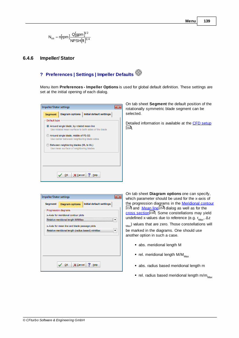
139Menu
© CFturbo Software & Engineering GmbH
43
21
ssftNPSH
gpmQrpmnN
6.4.6 Impeller/ Stator
? Preferences | Settings | Impeller Defaults
Menu item Preferences - Impeller Options is used for global default definition. These settings areset at the initial opening of each dialog.
On tab sheet Segment the default position of therotationally symmetric blade segment can beselected.
Detailed information is available at the CFD setup.
On tab sheet Diagram options one can specify,which parameter should be used for the x-axis ofthe progression diagrams in the Meridional contour
and Mean line dialog as well as for thecross section . Some constellations may yieldundefined x-values due to reference (e.g. r
Max, ∆z
Max) values that are zero. Those constellations will
be marked in the diagrams. One should useanother option in such a case.
abs. meridional length M
rel. meridional length M/MMax
abs. radius based meridional length m
rel. radius based meridional length m/mMax
284
210 254
156

140 CFturbo 9.2
© CFturbo Software & Engineering GmbH
abs. radius r
rel. radius r/rMax
abs. axial length z
rel. axial length ∆z/∆zMax
On tab sheet Initial default settings one canselect which settings should be used by defaultwhen creating a new design. Individual settings canbe specified for each machine type (Pump,Ventilator, Compressor, Turbine).
Of course these settings can be modified manuallyin the design step dialogs if required.
6.5 3D Model
Menu 3D Model is used for general handling of the 3D model.
Detailed description can be found in Views/ 3D Model .150

141Menu
© CFturbo Software & Engineering GmbH
6.6 3D Model - Blades
Menu 3D Model - Blades is used for handling geometries with blades (impeller, vaned stator) in thethe 3D model.
Because a project can contain multiple geometries with blades, these settings refer to the currentlyselected component in the model tree of the "3D Model" view. The name of the selected 3Dcomponent is displayed for information leftmost in the menu.
Detailed description can be found in Views/ 3D Model .
6.7 Report
Menu Report is used for handling the project report.
Detailed description can be found in Views/ Report .
157
150
164

142 CFturbo 9.2
© CFturbo Software & Engineering GmbH
6.8 Help
The Help menu supports the user on how to use CFturbo.
The following features are available:
Help topics General CFturbo online help, including help index
About CFturbo Information about CFturbo (e.g. version information)
Default Examples Open default examples folder of CFturbo installation
Check for updates Check for updates online
Show tutorials Show online tutorials for CFturbo
CFturbo website Open CFturbo website in browser
6.8.1 Check for Updates
? Help | Online | Check for updates
Here you can check for available updates on the CFturbo website. Most of all this concerns thefrequently released maintenance versions 9.1.x mainly provided for bug fixing.
The currently running version is displayed as well as the latest available for download. If an updatedversion is available a direct link to the download website is displayed. The download access (name +password) remains valid as long as a maintenance contract is running (time limited rental licensesinclude maintenance for the whole leasing period - there is no separate maintenance contractrequired).
142

143Menu
© CFturbo Software & Engineering GmbH
Update check can be executed automatically. This can be configured in Preferences/ General .132

Part
VII

145Views
© CFturbo Software & Engineering GmbH
7 Views
CFturbo offers 3 alternative views on the project in the central part of the main window:
Meridian
The diagram with the meridional view of the components gives an overview of the project andenables quick access to the components and the Interfaces in between.
3D Model
Shows the whole project as a 3D model.
Report
Presents a tabular view on the project information and the parameters of the components downto design step level.
The view can be selected by the buttons underneath the ribbons .
146
35
150
164
53
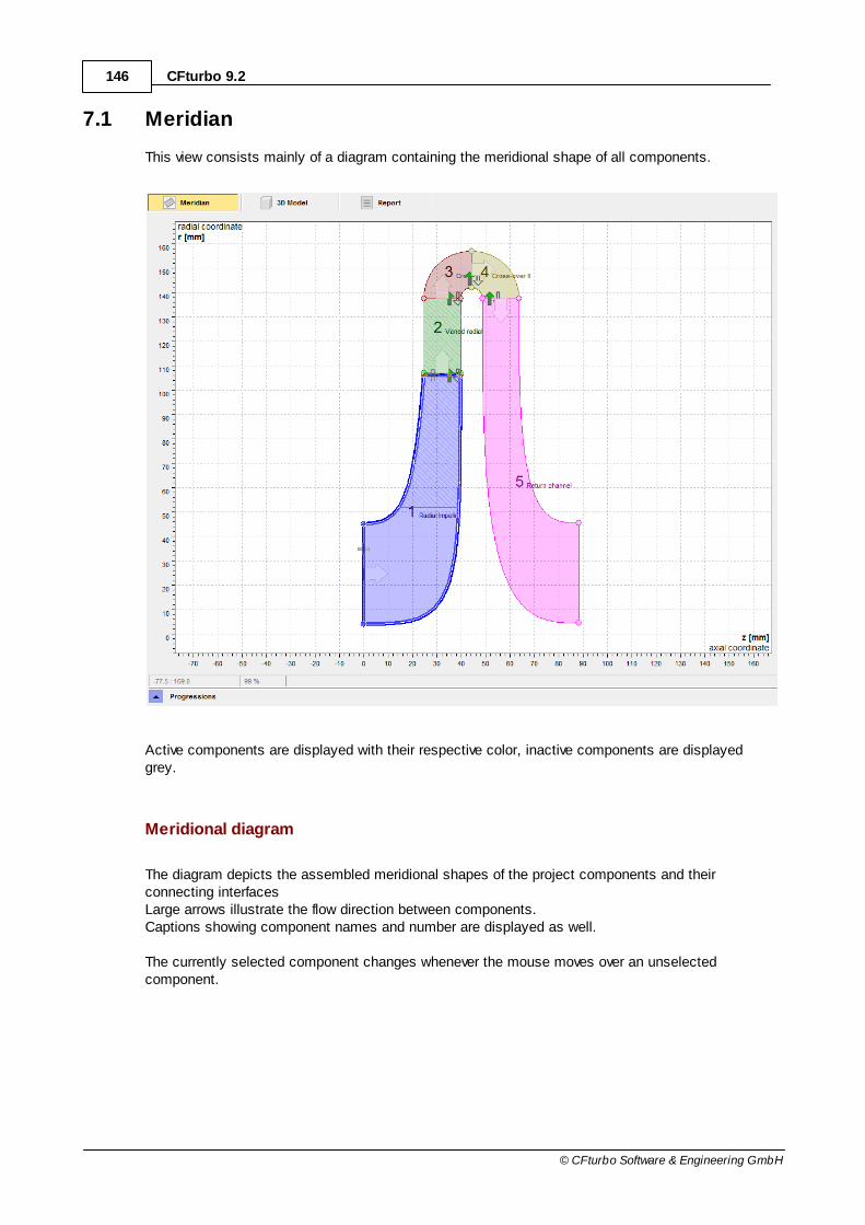
146 CFturbo 9.2
© CFturbo Software & Engineering GmbH
7.1 Meridian
This view consists mainly of a diagram containing the meridional shape of all components.
Active components are displayed with their respective color, inactive components are displayedgrey.
Meridional diagram
The diagram depicts the assembled meridional shapes of the project components and theirconnecting interfacesLarge arrows illustrate the flow direction between components.Captions showing component names and number are displayed as well.
The currently selected component changes whenever the mouse moves over an unselectedcomponent.

147Views
© CFturbo Software & Engineering GmbH
Component context menu
If the mouse moves over a component thecomponents menu is shown in compactstyle.
Adding Components
Via the symbol an additionalcomponent can be added to the project atthe symbols position. A menu shows the available componenttypes and the option to import an existingone (see also Add component ).119

148 CFturbo 9.2
© CFturbo Software & Engineering GmbH
Interfaces are located betweencomponents. The direction of the interfacecoupling is displayed by small symbols (seeleft). The coupling can be changed by moving themouse over a coupling symbol and selectinga coupling configuration from the appearingmenu.
Progression diagram
35

149Views
© CFturbo Software & Engineering GmbH
Below the meridional view, progressions of several physical quantities along the flow direction of allcomponents can be displayed:
Selectable Progressions
A Cross section area
cm
Meridional velocity
cu
Circumferential velocity
c Absolute velocity
α Flow angle

150 CFturbo 9.2
© CFturbo Software & Engineering GmbH
7.2 3D Model
Tab sheet 3D Model contains the three dimensional representation of the project design state.
The CAD model can be exported as IGES, STEP or STL - see Export . For export, only thecurrently visible geometrical elements are considered.
Navigation
The 3D display can be influenced by mouse:
Rotate Rotation around point of origin
Zoom Zoom (also mouse wheel) Rotation around z-axis
Move Move
The functions can be assigned to mouse buttons via Preferences/ General .
Menus
70
132

151Views
© CFturbo Software & Engineering GmbH
Above the 3D representation in the menus 3D Model and 3D Model - Blades you can find buttonswhich have only an optical effect but do not change the geometry model.
Model display (top)
Model tree
Left of the 3D representation is the Model tree. There, all available geometry parts are listed in atree structure, whereby they can be configured individually.
Model tree (left)
3D-Preview
In many design step dialogs a 3D-Preview of the currently designed part can be displayed via the Additional views button at the top.
The 3D-Preview behaves in the same way as the 3D Model view described above. For performancereasons, the 3D objects are displayed with coarse resolution only.
Limitation: The 3D-Preview is not available when working remote (i.e. via RDP) or inside a virtualmachine.
See also:
Problems when generating surfaces/solids
Open/ Save design
Data export
7.2.1 Model display (top)
? 3D Model
The following actions are available by the buttons of the 3D Model tab. They are used forvisualization only and do not affect the geometry model.
151
157
161
56
70

152 CFturbo 9.2
© CFturbo Software & Engineering GmbH
General
Save representation as PNG, JPG, GIF or BMP
Print representation
View (rotation, translation, zoom)
Fit view (zoom all geometry to visible region)
Viewing direction in positive or negative (< >) x-axis direction
Viewing direction in positive or negative (< >) y-axis direction
Viewing direction in positive or negative (< >) z-axis direction
Reset view (default position)
Load view from file
Save current view to file
Settings
Switch coordinate system on/off
Switch scale system on/off
Set background color

153Views
© CFturbo Software & Engineering GmbH
A uniform rotation of the impeller around the z axis can be generated, whereby the velocitycan be influenced by the track bar.
Select resolution of curves and surfaces (affects display)
Coarse
Middle
Fine
Define line width for points
Define line width for curves
Set number of surface isocurves
Clipping
A clipping plane for x=const., y=const. or z=const. can be defined and optionally displayed. Theposition of the clipping plane can be adjusted by the track bar.
? 3D Model - Blades

154 CFturbo 9.2
© CFturbo Software & Engineering GmbH
The following actions are available through buttons of the 3D Model - Blades tab. They are used forvisualization only and do not affect model geometry.
Please note: The following options refer to the component currently selected in the 3D model tree.
Only single blade
Blade passage
Display a single blade passage bordered by 2 neighboring blades.
157

155Views
© CFturbo Software & Engineering GmbH
Show section
The display of an approximately perpendicularly flown through area between hub, shroudand two neighboring blades can be generated for the component currently selected in themodel tree. The position of this area can optionally be fixed to the location of the throatarea (Fix to minimum). Otherwise, it can be slided to any reasonable position within the
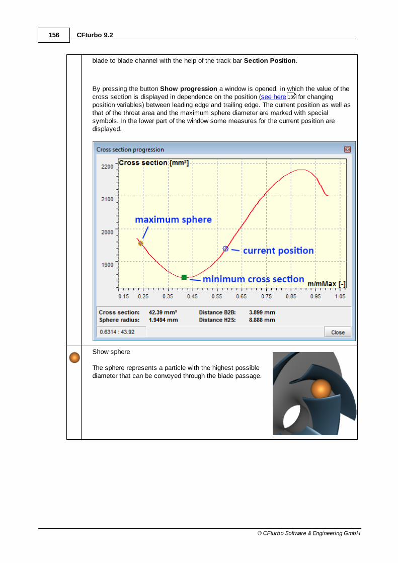
156 CFturbo 9.2
© CFturbo Software & Engineering GmbH
blade to blade channel with the help of the track bar Section Position.
By pressing the button Show progression a window is opened, in which the value of thecross section is displayed in dependence on the position (see here for changingposition variables) between leading edge and trailing edge. The current position as well asthat of the throat area and the maximum sphere diameter are marked with specialsymbols. In the lower part of the window some measures for the current position aredisplayed.
Show sphere
The sphere represents a particle with the highest possiblediameter that can be conveyed through the blade passage.
139
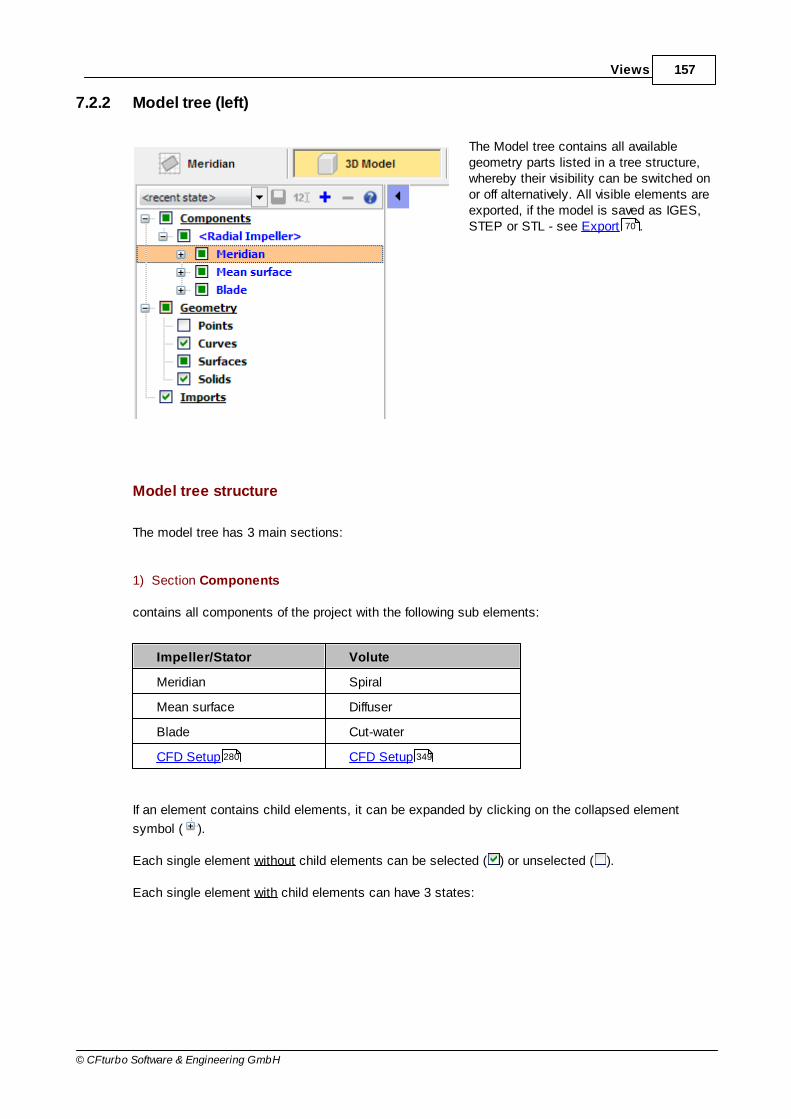
157Views
© CFturbo Software & Engineering GmbH
7.2.2 Model tree (left)
The Model tree contains all availablegeometry parts listed in a tree structure,whereby their visibility can be switched onor off alternatively. All visible elements areexported, if the model is saved as IGES,STEP or STL - see Export .
Model tree structure
The model tree has 3 main sections:
1) Section Components
contains all components of the project with the following sub elements:
Impeller/Stator Volute
Meridian Spiral
Mean surface Diffuser
Blade Cut-water
CFD Setup CFD Setup
If an element contains child elements, it can be expanded by clicking on the collapsed element
symbol ( ).
Each single element without child elements can be selected ( ) or unselected ( ).
Each single element with child elements can have 3 states:
70
280 349

158 CFturbo 9.2
© CFturbo Software & Engineering GmbH
The element and all child elements areselected.
The element and not all child elementsare selected.
The element is unselected. Childelements might be selected.
An element is visible in the 3D view, if it is selected and all its parent elements are alsoselected.
Note: If the <Ctrl> key is pressed while selecting an element, all child elements are selected, too!
2) Section Geometry
contains all basic geometrical types:
Points
Curves
Surfaces
Solids
This allows:
to select all objects of a certain geometrical type. In the 3D view, only those elementsbecome visible, whose parent elements are selected also.
to modify the display properties of all currently visible objects of a certain geometrical type.
3) Section Imports
This section contains all imported geometric models including CFturbo components of referenceprojects or simply imported 3D models .
Visibility and render properties for imported models can be modified in the same way as forcomponents of Section Components.
115 115

159Views
© CFturbo Software & Engineering GmbH
Right clicking on items in the Imports section provides a context menu with additional import relatedoptions:
Transform geometry - applies user defined geometric transformations to currently selectedimport.
Remove - removes selected import from model tree and 3D view.
Remove all - removes all imported models from model tree and 3D view.
Export as - exports selected import in its transformed state. (This option is notavailable for STL imports.)
The option Transform geometry is intended to help align imported component models with theproject model to make visual comparisons of the model shapes more convenient. To this end, anynumber of simple transformations can be applied via the dialog that opens when Transform geometryis selected.
The Transform geometry dialog allows the application of fourdifferent types of geometric transformations, accessible byclicking on the corresponding symbols (from left to right:translation, rotation, uniform scaling, mirroring).
Translations can be applied iteratively along the coordinateaxes.
Rotations can be applied iteratively around the coordinateaxes.
Uniform model scaling is applied in absolute (percentage)terms.
Mirroring is toggled for the models coordinate system in all

160 CFturbo 9.2
© CFturbo Software & Engineering GmbH
three coordinate directions.
To apply a transformation to the current model, select atransformation type, set its parameters and click the Applybutton (or hit Enter).
The model transformation can be reset to the state which itwas imported with by clicking the reset button.
Useful transformations for an imported model can be saved for later use by exporting the model withits current transformation via the context menu (--> Export as, see above).
Display properties
The elements selected in the model tree are highlighted in the 3D view. The following attributes canbe defined below the model tree:
Wireframe display
Shaded surface display
Shaded surface display with edges orisocurves
Material
Color
Transparency
The selection can be cleared by pressing the <Esc> key.
Model states
Model states contain the properties of all tree elements. Several model states can be managed viathe controls above the model tree.
Select existing model state
Save model state
Rename selected model state

161Views
© CFturbo Software & Engineering GmbH
Add new model state
Delete selected model state
Three model states are predefined and cannot be modified:
"Default" The default model state
"Default + CFD Setup" The default model state with CFD Setup visible
"Solids only" Only solids are visible
"Component colors" Every component is displayed with the color defined in the Componentsview
For performance reasons, model states do not contain the state of each individual 3D object, butonly to the level of distinction between different geometrical types (points, curves, surfaces).Therefore, e.g. all faces that belong to a "solid faces" object share the same properties.
7.2.3 Problems when generating the 3D model
Information about 3D-Errors
If any errors occur while generating geometrical elements then thecorresponding part in the model tree is marked by red color.
Furthermore, a corresponding error message is displayed in the message panel .
Possible warnings
Problem Possible solutions
3D-Error: Could not create solid ...
Distance tolerance is too low or too high Change the distance tolerance
(see Model settings )
146
47
288

162 CFturbo 9.2
© CFturbo Software & Engineering GmbH
Problem Possible solutions
Number of data points is disadvantageous(seldom)
Change the number of data points for the 3Dmodel
(see Model settings )
Eliminating errors during surface generation
For eliminating errors during surface generation there exist the following possibilities:
try a different number of data points for the 3D model (see Impeller- or Volute-Settings)
try a different display resolution (see Model display (top) )
The pictures illustratethe possible influence ofpoint density on thesurface generation of theblade.
Surface display errors
It may occur that a surface is not displayed although it exists.
288
288
349
151

163Views
© CFturbo Software & Engineering GmbH
You can recognize such cases by selecting the surface in the model tree and choosing a highnumber of isocurves (see Model display (top) ).
Normally, choosing another resolution (see Model display (top) ) solves this problem.
The orange iso-curvesshow how the surfacelooks like.
Slow 3D model
If the handling of the 3D model is very slow, normally an update of the graphic card driver ishelpful.
If problems occur inconnection with thegraphic card,sometimes an unsteadymesh is displayed onthe faces of the solids.
151
151

164 CFturbo 9.2
© CFturbo Software & Engineering GmbH
7.3 Report
The report shows the most important information about the design in a tabular style.
In the tree, the project information and the global setup parameters are listed prior to thecomponents. Tree elements containing sub elements can be collapsed and expanded.
The buttons of the Report tab on the ribbon have the following function
Save report as HTML, RTF, CSV or TXT
Print report
Copy the content to the clipboardAll marked rows are copied. If nothing is marked then all content is copied.Marking can be done by mouse, <Crtl> <A> marks all. Content will be pasted in MS Word/Excel as table.
Expand all nodes
Collapse all nodes

Part
VIII
166 CFturbo 9.2
© CFturbo Software & Engineering GmbH
8 Impeller
? Impeller
This chapter describes in detail the design process for all impeller typecomponents featured in CFturbo.
The content reflects the design steps in the sequence they are encounteredduring the design process.
Design steps
Main dimensions
Meridional contour
Blade properties
Blade mean lines
Blade profiles
Blade edges
Model finishing
Model settings
CFD setup
8.1 Main dimensions
? Impeller | Main dimensions
The Main Dimensions menu item is used to define main dimensions of the impeller.
Details by impeller type
Pump/Ventilator
Compressor
Turbine
166
210
234
254
270
274
290
288
280
167
182
196

167Impeller
© CFturbo Software & Engineering GmbH
Possible warnings
Problem Possible solutions
Main dimensions are updated automatically.Therefore geometry modifications are possible.
Main dimensions are updated automatically ifany input parameters are modified.
To fix the main dimensions you could uncheckthe "Automatic" calculation. Then you have tomanually start the calculation if required.
Main dimensions are not updated automatically.Therefore the design could be not up-to-date.
Main dimensions are not updated automaticallyif any input parameters are modified.
To be sure that all parameter modifications areconsidered you could switch to an automaticcalculation by checking the "Automatic" option.
8.1.1 Pump / Ventilator
? Impeller | Main dimensions
The Main Dimensions menu item is used to define main dimensions of the impeller. MainDimensions are forming the most important basis for all following design steps.

168 CFturbo 9.2
© CFturbo Software & Engineering GmbH
The real flow in a pump impeller is turbulent and three-dimensional. Secondary flows, separation and reattachment inboundary layers, cavitation, transient recirculation areas andother features may occur. Nevertheless it is useful - and it iscommon practice in the pump design theory - to simplify therealistic flow applying representative streamlines for the firstdesign approach.
Employing 1D-streamline theory the following cross sections aresignificant in particular: suction area (index S), just beforeleading edge (index 0), at the beginning (index 1) and at the endof the blade (index 2) and finally behind the trailing edge (index3).
Details
Setup
Parameters
Dimensions
169
170
177
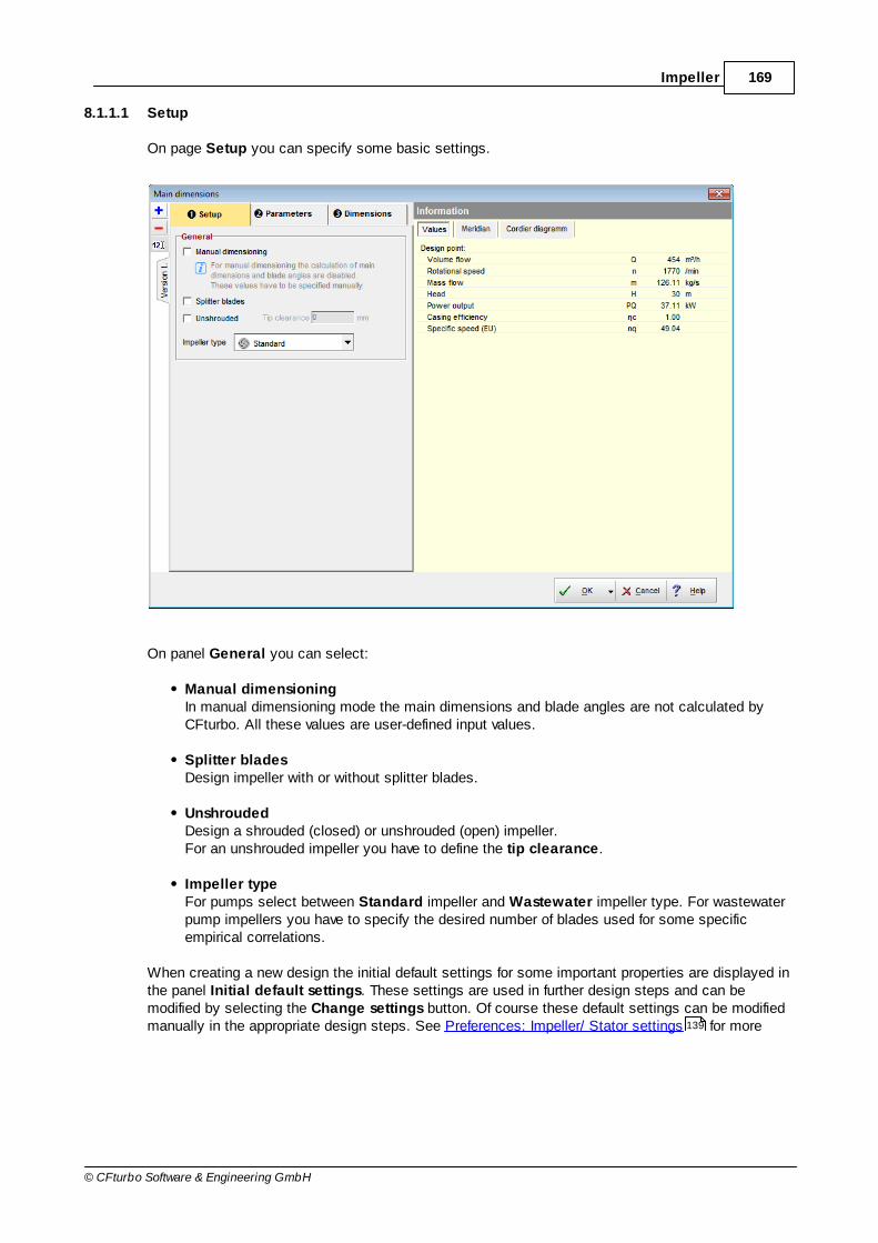
169Impeller
© CFturbo Software & Engineering GmbH
8.1.1.1 Setup
On page Setup you can specify some basic settings.
On panel General you can select:
Manual dimensioningIn manual dimensioning mode the main dimensions and blade angles are not calculated byCFturbo. All these values are user-defined input values.
Splitter bladesDesign impeller with or without splitter blades.
UnshroudedDesign a shrouded (closed) or unshrouded (open) impeller.For an unshrouded impeller you have to define the tip clearance.
Impeller typeFor pumps select between Standard impeller and Wastewater impeller type. For wastewaterpump impellers you have to specify the desired number of blades used for some specificempirical correlations.
When creating a new design the initial default settings for some important properties are displayed inthe panel Initial default settings. These settings are used in further design steps and can bemodified by selecting the Change settings button. Of course these default settings can be modifiedmanually in the appropriate design steps. See Preferences: Impeller/ Stator settings for more139
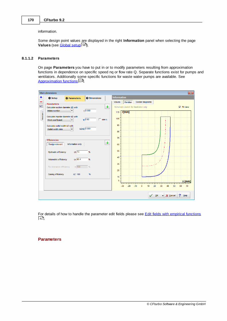
170 CFturbo 9.2
© CFturbo Software & Engineering GmbH
information.
Some design point values are displayed in the right Information panel when selecting the pageValues (see Global setup ).
8.1.1.2 Parameters
On page Parameters you have to put in or to modify parameters resulting from approximationfunctions in dependence on specific speed nq or flow rate Q. Separate functions exist for pumps andventilators. Additionally some specific functions for waste water pumps are available. See Approximation functions .
For details of how to handle the parameter edit fields please see Edit fields with empirical functions.
Parameters
58
124
41

171Impeller
© CFturbo Software & Engineering GmbH
The panel Parameters allows defining alternativeparameters in each case for the calculation of the followingimpeller main dimensions:
for pumps for ventilators
suction diameter dS
inlet diameter d1
inlet width b1
impeller diameter d2
impeller width b2
For dS-calculation (pumps)
Intake coefficient ε
Ratio between meridional inflow velocity and specific energy
Y2c0
0.05…0.4 (rising with nq)
(km1
at Stepanoff)
Inflow angle 0a
high smaller dimensions, lower friction losses
< 20° prevent the risk of cavitation
> 15° with regard to efficiency
12°...17° recommended for good suction capability
Minimal relativevelocity w
small friction and shock losses
only if no cavitation risk !
fdS
=1.15...1.05 standard impeller, nq=15...40
fdS
=1.25...1.15 suction impeller

172 CFturbo 9.2
© CFturbo Software & Engineering GmbH
suction specificspeed n
SS
43R
31
SS]m[NPSH
smQminnn
(European definition for illustration)
Standard suction impeller u1<50 m/s 160...220
Suction impeller, axial inflow u1<35 m/s 220...280
Suction impeller, cont. shaft u1<50 m/s 180...240
High pressure pump u1>50 m/s 160...190
Standard inducer u1>35 m/s 400...700
Rocket inducer >>1000
Min. NPSH
g2
w
g2
cNPSH
21
w
21m
cR
c suction pressure coefficient for absolute velocity c (inflow acceleration
and losses): 1.1 axial inflow; 1.2…1.35 radial inflow casing
w Unterdruckbeiwert für Relativgeschwindigkeit w (Druckabsenkung an
der Vorderkante): 0.10…0.30 standard impeller; 0.03…0.06 inducer
for d1 calculation (ventilator)
Diameter ratio d1/d
2v
65
2
1 25.1d
d
for b1 calculation (ventilator)
Meri. decelerationc
m1/c
mS
216.2d
b4
c
c 61
1
1
mS
1m
For d2-calculation
Work coefficient ψ
dimensionless expression for the specific energy:
222
2
2
2 uYuY eff and
0.7 ...1.3 radial impeller0.25...0.7 mixed-flow impeller0.1 ...0.4 axial impeller

173Impeller
© CFturbo Software & Engineering GmbH
high small d2, flat characteristic curve
low high d2, steep characteristic curve
If the check box "use η" is set d2-calculation is done on the basis of
Yef f
=Y/η. Otherwise Y - specific work without losses - is used.
Diameter coefficient δ according to Cordier diagram (see Dimensions )
Outflow angle 3 6°...13°: recommended for stable performance curve (with nq rising)
For b2-calculation
Outlet width ratio
b2/d
2
0.04...0.30 (rising with nq)
for pumps:
Mer. deceleration
cm3
/cmS
0.60...0.95 (rising with nq)
for pumps:
Outlet coefficient ε2
Ratio between meridional outlet velocity and specific energy
Y2c 2m2
0.08…0.26 (rising with nq)
(km2
at Stepanoff)
for ventilators:
Shroud angle εShr
2002arctan12
21
dd
bbShr
Efficiency
In panel Efficiency you have to specify several efficiencies. You have to distinguish between designrelevant efficiencies and efficiencies used for information only:
Design relevant
177

174 CFturbo 9.2
© CFturbo Software & Engineering GmbH
hydraulic efficiency ηh
volumetric efficiency ηv
tip clearance efficiency ηT
Information only
side friction efficiency ηS
mechanical efficiency ηm
motor efficiency ηmot
casing efficiency ηc (displayed for information only, see Global setup )
The casing efficiency ηc is used additionally for impeller dimensioning in order to compensate the
flow losses in the casing.
The losses resulting in energy dissipation from the fluid form the impeller efficiency.
TSvhIm
Impeller, casing and mechanical efficiency form the overall efficiency (coupling efficiency) of thestage η
St.
When considering motor losses additionally the overall efficiency of the stage incl. motor ηSt
* is
defined.
mcImD
QSt
P
P PQ: pump output, see above
PD: mechanical power demand (coupling/ driving power)
motStel
Q*St
P
PP
el: electrical power demand of motor
The following summary illustrates the single efficiencies and their classification:
classification efficienciesRelevant forimpeller design
58

175Impeller
© CFturbo Software & Engineering GmbH
stage
casing ηC casing
yes: for energytransmission
impeller
ηh hydraulic
ηT tip
ηV volumetric yes: for flow rate
ηS side friction
no: for overallinformation only
mechanical ηm mechanical
stage incl. motor electrical ηmot motor
The obtainable overall efficiency correlates to specific speed and to the size and the type of theimpeller as well as to special design features like bypass installations and auxiliary aggregates.Efficiencies calculated by approximation functions are representing the theoretical reachablevalues and they should be corrected by the user if more information about the impeller or the wholepump are available.
The hydraulic efficiency (or blade efficiency) describe the energy losses within the pump caused byfriction and vorticity. Friction losses mainly originate from shear stresses in boundary layers.Vorticity losses are caused by turbulence and on the other hand by changes of flow cross sectionand flow direction which may lead to secondary flow, flow separation, wake behind blades etc.. Thehydraulic efficiency is the ratio between specific energy Y and the energy transmitted by the impellerblades:
93.085.0Y~Y
h
The volumetric efficiency is a quantity for the deviation of effective flow rate Q from total flow rate
inside the impeller Q~
which also includes the circulating flow within the pump casing:
99.093.0Q~Q
v
(rising with impeller size)
The tip clearance efficiency is only relevant for unshrouded impellers. It contains losses due to theflow through the gap between blade tips and housing from the pressure to the suction side of theblades. The flow losses mainly depend on the tip clearance distance x
T and decrease with rising
number of blades and rising blade outlet angle 2.
124

176 CFturbo 9.2
© CFturbo Software & Engineering GmbH
2TRatioRatioqRatioT bxAA,nffAf1
The side friction efficiency contains losses caused by rotation of fluid between hub/ shroud andhousing:
40nfür995.0985.0
40nfür985.05.0
P
P1
q
qSS
The mechanical efficiency mainly includes the friction losses in bearings and seals:
995.095.0P
P1 m
m
(rising with impeller size)
Hydraulic and volumetric efficiency as well as the tip clearance efficiency are most important for the
impeller dimensioning because of their influence to Y~
and/or Q~
. Mechanical and side frictionefficiency are affecting only the required driving power of the machine.
Information
In the right area of the register Parameter you can find again some calculated values forinformation:
Required driving powerSt
QD
PP
Power loss StDQDL 1PPPP
Impeller efficiency TSvhIm
Stage efficiency cmImD
QSt
P
P
Stage efficiency incl. motor motStel
Q*St
P
P

177Impeller
© CFturbo Software & Engineering GmbH
8.1.1.3 Dimensions
On page Dimensions, panel Shaft/ hub, the required shaft diameter is computed and the hubdiameter is determined by the user.
Shaft/Hub
The main dimensions of a designed impeller - suctiondiameter d
S, impeller diameter d
2, outlet width b
2 -
can be seen on Main dimensions panel. They canbe recomputed by pressing the Calculate-button.The computation is based on "Euler's Equation ofTurbomachinery", on the continuity equation and therelations for the velocity triangles as well as on theparameters and parameter ratios given in the tabsheets Design Point and Parameters.
You may accept the proposed values or you canmodify them slightly, e.g. to meet a certainnormalized diameter.
In case the checkbox Automatic is activated a new calculation will accomplished after any changeof parameter. Then the manual alteration of the main dimensions is not possible.
Regarding the impeller size one should try to attain d2 values as low as possible. But there is a limit
for a specified task: lower impeller diameters are leading to higher blade loading - up to blade angles
2 which may not be suitable anymore.
209
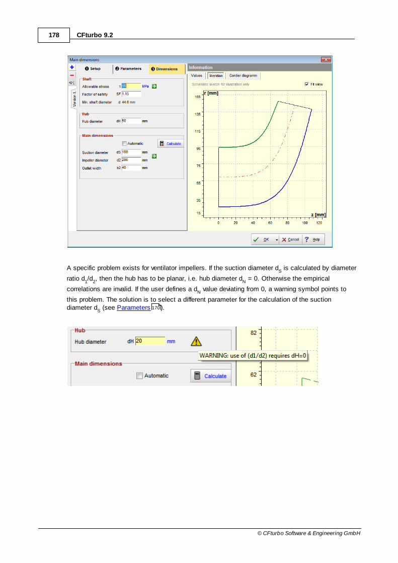
178 CFturbo 9.2
© CFturbo Software & Engineering GmbH
A specific problem exists for ventilator impellers. If the suction diameter dS is calculated by diameter
ratio d1/d
2, then the hub has to be planar, i.e. hub diameter d
N = 0. Otherwise the empirical
correlations are invalid. If the user defines a dN value deviating from 0, a warning symbol points to
this problem. The solution is to select a different parameter for the calculation of the suctiondiameter d
S (see Parameters ).170
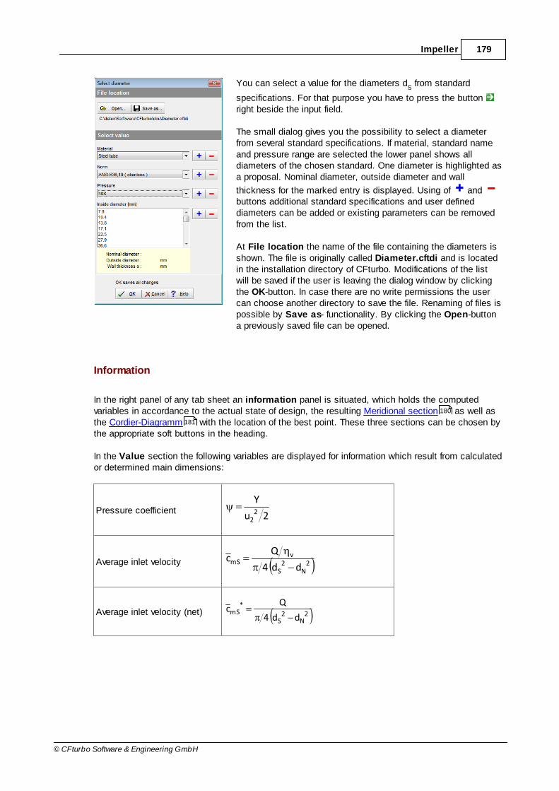
179Impeller
© CFturbo Software & Engineering GmbH
You can select a value for the diameters dS from standard
specifications. For that purpose you have to press the button right beside the input field.
The small dialog gives you the possibility to select a diameterfrom several standard specifications. If material, standard nameand pressure range are selected the lower panel shows alldiameters of the chosen standard. One diameter is highlighted asa proposal. Nominal diameter, outside diameter and wall
thickness for the marked entry is displayed. Using of and buttons additional standard specifications and user defineddiameters can be added or existing parameters can be removedfrom the list.
At File location the name of the file containing the diameters isshown. The file is originally called Diameter.cftdi and is locatedin the installation directory of CFturbo. Modifications of the listwill be saved if the user is leaving the dialog window by clickingthe OK-button. In case there are no write permissions the usercan choose another directory to save the file. Renaming of files ispossible by Save as- functionality. By clicking the Open-buttona previously saved file can be opened.
Information
In the right panel of any tab sheet an information panel is situated, which holds the computedvariables in accordance to the actual state of design, the resulting Meridional section as well asthe Cordier-Diagramm with the location of the best point. These three sections can be chosen bythe appropriate soft buttons in the heading.
In the Value section the following variables are displayed for information which result from calculatedor determined main dimensions:
Pressure coefficient2u
Y2
2
Average inlet velocity 2N
2S
vmS
dd4
Qc
Average inlet velocity (net) 2N
2S
*mS
dd4
Qc
180
181

180 CFturbo 9.2
© CFturbo Software & Engineering GmbH
Average outlet velocity22
v3m
bd
Qc
Average outlet velocity (net)22
*3m
bd
Qc
NPSH valueg2
w
g2
cNPSH
21
w
21m
cR
or34
SSqR nnHNPSH
Outlet width ratio b2/d
2
Meridional deceleration mS3mcm ccd
Estimated axial force2
N2
Sax dd4gH9.0F
The Meridional preview is based on the until now designed main dimensions.
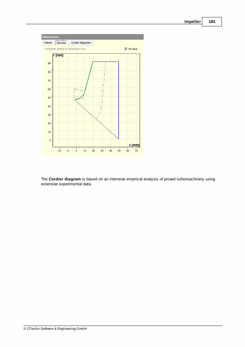
181Impeller
© CFturbo Software & Engineering GmbH
The Cordier diagram is based on an intensive empirical analysis of proved turbomachinery usingextensive experimental data.

182 CFturbo 9.2
© CFturbo Software & Engineering GmbH
8.1.2 Compressor
? Impeller | Main dimensions
The Main Dimensions menu item is used to define main dimensions of the impeller. MainDimensions are forming the most important basis for all following design steps.
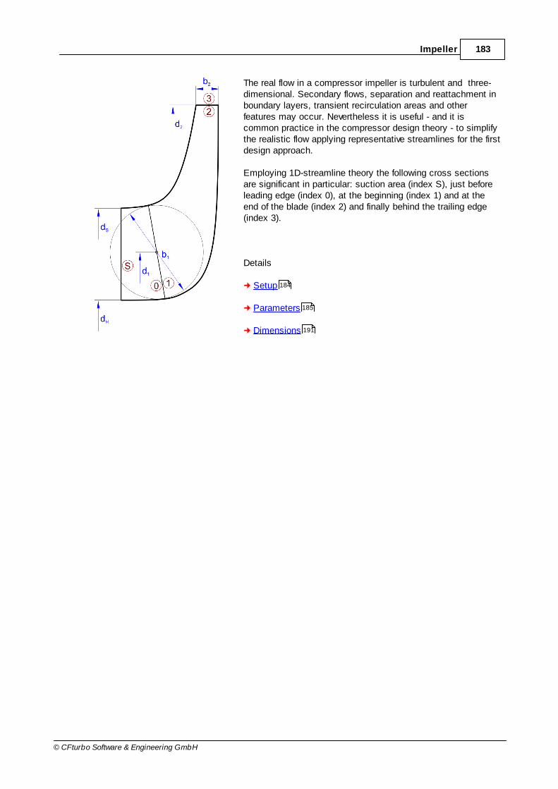
183Impeller
© CFturbo Software & Engineering GmbH
The real flow in a compressor impeller is turbulent and three-dimensional. Secondary flows, separation and reattachment inboundary layers, transient recirculation areas and otherfeatures may occur. Nevertheless it is useful - and it iscommon practice in the compressor design theory - to simplifythe realistic flow applying representative streamlines for the firstdesign approach.
Employing 1D-streamline theory the following cross sectionsare significant in particular: suction area (index S), just beforeleading edge (index 0), at the beginning (index 1) and at theend of the blade (index 2) and finally behind the trailing edge(index 3).
Details
Setup
Parameters
Dimensions
184
185
191

184 CFturbo 9.2
© CFturbo Software & Engineering GmbH
8.1.2.1 Setup
On page Setup you can specify some basic settings.
On panel General you can select:
Manual dimensioningIn manual dimensioning mode the main dimensions and blade angles are not calculated byCFturbo. All these values are user-defined input values.
Splitter bladesDesign impeller with or without splitter blades.
UnshroudedDesign a shrouded (closed) or unshrouded (open) impeller.For an unshrouded impeller you have to define the tip clearance.
When creating a new design the initial default settings for some important properties are displayed inthe panel Initial default settings. These settings are used in further design steps and can bemodified by selecting the Change settings button. Of course these default settings can be modifiedmanually in the appropriate design steps. See Preferences: Impeller/ Stator settings for moreinformation.
139
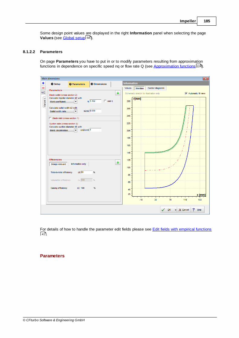
185Impeller
© CFturbo Software & Engineering GmbH
Some design point values are displayed in the right Information panel when selecting the pageValues (see Global setup ).
8.1.2.2 Parameters
On page Parameters you have to put in or to modify parameters resulting from approximationfunctions in dependence on specific speed nq or flow rate Q (see Approximation functions ).
For details of how to handle the parameter edit fields please see Edit fields with empirical functions.
Parameters
58
124
41
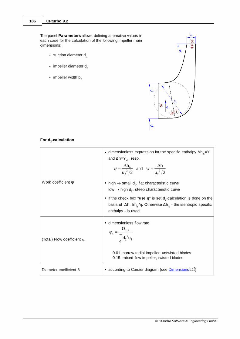
186 CFturbo 9.2
© CFturbo Software & Engineering GmbH
The panel Parameters allows defining alternative values ineach case for the calculation of the following impeller maindimensions:
suction diameter dS
impeller diameter d2
impeller width b2
For d2-calculation
Work coefficient ψ
dimensionless expression for the specific enthalpy ∆his=Y
and ∆h=Yef f
resp.
222
2
2
2 u
h
u
his and
high small d2, flat characteristic curve
low high d2, steep characteristic curve
If the check box "use η" is set d2-calculation is done on the
basis of ∆h=∆his/η. Otherwise ∆h
is - the isentropic specific
enthalpy - is used.
(Total) Flow coefficient t
dimensionless flow rate
22
2
S,tt
ud4
Q
0.01 narrow radial impeller, untwisted blades0.15 mixed-flow impeller, twisted blades
Diameter coefficient δ according to Cordier diagram (see Dimensions )191

187Impeller
© CFturbo Software & Engineering GmbH
Machine Mach number Mau
dimensionless peripheral speed of impeller related to totalinlet speed of sound
S,t
2u
a
uMa
Peripheral speed u2 Limiting values due to strength as a function of the material
For b2-calculation
Outlet width ratio b2/d
2 0.01...0.15 (with nq rising)
Meridional flow coefficient m
dimensionless flow rate
2
m2
222
2m
u
c
ubd
Q
0.10...0.50 (with nq rising)
For d1-calculation (optional)
Diameter ratio d1/d
2d
1/d
2=0.3...0.8
Relative deceleration w2/w
1w
2/w
1>0.7 or f(b
2/d
2)
For b1-calculation (optional)
Meridional deceleration cm2
/cm1
cm2
/cm1
= 0.8...1.25
for dS-calculation
Meridional decelerationc
m1/c
mS or
cm2
/cmS
cm1
/cmS
= 0.9...1.1
cm2
/cmS
= 0.7...1.3

188 CFturbo 9.2
© CFturbo Software & Engineering GmbH
Relative inlet flow angle βS
30cu
carctan
w
carctan
uSS
mS
uS
mSS
Relative inlet Mach number MwS 85.075.0
a
wc
a
wM
S
2uS
2mS
S
SwS
The relative inlet Mach number can be implemented in a certain range only. The lower limit is givenby the fact that small values for dS (high meridional velocity c
mS) as well as high values for dS (high
rotational speed uS and therefore w
uS) result in an increasing relative velocity w
S. Due to the square
root equation of MwS
two different values of dS are possible. For certain boundary conditions a
minimal relative velocity and therefore a minimal relative inlet Mach number is existing always.
In this context it's important to know that the fluid density is dependent on the velocity and thereforeon the geometrical dimensions.
Efficiency
In panel Efficiency you have to specify several efficiencies. You have to distinguish between designrelevant efficiencies and efficiencies used for information only:
Design relevant
flow efficiency ηtt
(total-total)
volumetric efficiency ηv
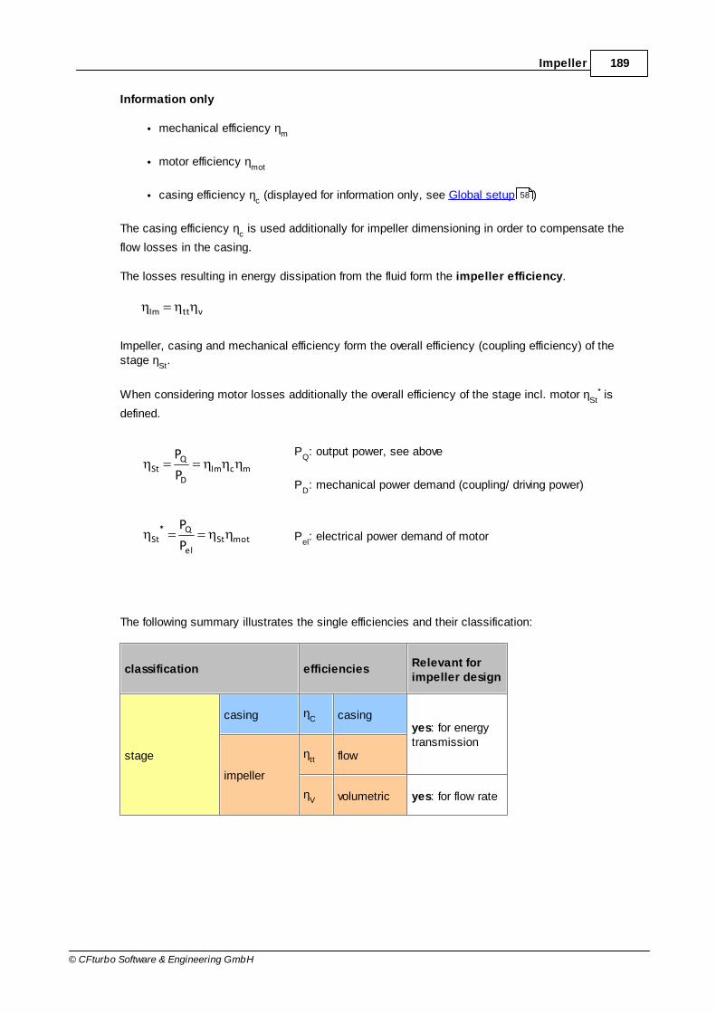
189Impeller
© CFturbo Software & Engineering GmbH
Information only
mechanical efficiency ηm
motor efficiency ηmot
casing efficiency ηc (displayed for information only, see Global setup )
The casing efficiency ηc is used additionally for impeller dimensioning in order to compensate the
flow losses in the casing.
The losses resulting in energy dissipation from the fluid form the impeller efficiency.
vttIm
Impeller, casing and mechanical efficiency form the overall efficiency (coupling efficiency) of thestage η
St.
When considering motor losses additionally the overall efficiency of the stage incl. motor ηSt
* is
defined.
mcImD
QSt
P
P PQ: output power, see above
PD: mechanical power demand (coupling/ driving power)
motStel
Q*St
P
PP
el: electrical power demand of motor
The following summary illustrates the single efficiencies and their classification:
classification efficienciesRelevant forimpeller design
stage
casing ηC casing
yes: for energytransmission
impeller
ηtt flow
ηV volumetric yes: for flow rate
58

190 CFturbo 9.2
© CFturbo Software & Engineering GmbH
mechanical ηm mechanical
no: for overallinformation only
stage incl. motor electrical ηmot motor
The obtainable overall efficiency correlates to specific speed and to the size and the type of theimpeller as well as to special design features like bypass installations and auxiliary aggregates.Efficiencies calculated by approximation functions are representing the theoretical reachablevalues and they should be corrected by the user if more information about the impeller or the wholemachine are available.
The impeller efficiency tt describes the energy losses caused by friction and vorticity. Friction
losses mainly originate from shear stresses in boundary layers. Vorticity losses are caused byturbulence and on the other hand by changes of flow cross section and flow direction which maylead to secondary flow, flow separation, wake behind blades etc.. The impeller efficiency is the ratiobetween the actual specific energy Y and the energy transmitted by the impeller blades without anylosses:
Y~Y
tt
The volumetric efficiency is a quantity for the deviation of effective flow rate Q from total flow rate
inside the impeller Q~
which also includes the circulating flow within the casing:
99.093.0Q~Q
v
(rising with impeller size)
The mechanical efficiency mainly includes the friction losses in bearings and seals:
995.0...95.0P
P1 m
m
(rising with impeller size)
Impeller efficiency and volumetric efficiency are most important for the impeller dimensioning
because of their influence to Q~
and/or Y~
. The mechanical efficiency is affecting only the requireddriving power of the machine.
Information
In the right panel of the tab sheet Parameter you can find again some calculated values forinformation:
124

191Impeller
© CFturbo Software & Engineering GmbH
Required driving powerSt
QD
PP
Power loss StDQDL 1PPPP
Impeller efficiency vttIm
Stage efficiency cmImD
QSt
P
P
Stage efficiency incl. motor motStel
Q*St
P
P
Total-to-static efficiency 1
1Tc2
c1
t
tSp
22
1
t
ts
(perfect gas model)
8.1.2.3 Dimensions
On page Dimensions, panel Shaft/ hub, the required shaft diameter is computed and the hubdiameter is determined by the user.
Shaft/Hub 209

192 CFturbo 9.2
© CFturbo Software & Engineering GmbH
The main dimensions of a designed impeller - suctiondiameter d
S, impeller diameter d
2, outlet width b
2 -
can be seen on Main dimensions panel. They canbe recomputed by pressing the Calculate-button.The computation is based on "Euler's Equation ofTurbomachinery", on the continuity equation and therelations for the velocity triangles as well as on theparameters and parameter ratios given in the tabsheets Design Point and Parameters.
You may accept the proposed values or you canmodify them slightly, e.g. to meet a certainnormalized diameter.
In case the checkbox Automatic is activated a new calculation will accomplished after any changeof parameter. Then the manual alteration of the main dimensions is not possible.
Regarding the impeller size one should try to attain d2 values as low as possible. But there is a limit
for a specified task: lower impeller diameters are leading to higher blade loading - up to blade angles
2 which may not be suitable anymore.

193Impeller
© CFturbo Software & Engineering GmbH
Information
In the right panel of any tab sheet an information panel is situated, which holds the computedvariables in accordance to the actual state of design, the resulting Meridional section as well asthe Cordier-Diagramm with the location of the best point. These three sections can be chosen bythe appropriate soft buttons in the heading.
In the Value section the following variables are displayed for information which result from calculatedor determined main dimensions:
Pressure coefficient 5.16.02u
Y2
2
Flow coefficient15.001.0
ud4
Q
22
2
S,tt
194
195

194 CFturbo 9.2
© CFturbo Software & Engineering GmbH
Meridional flow coefficient 5.01.0u
c
ubd
Q
2
m2
222
2m
Tangential force coefficient 63cmtt
t
Outlet width ratio b2/d
2 = 0.01...0.15
Diameter ratio dS/d
2
Inlet Mach number 85.075.0RZT
wwMa
S
2uS
2mS
wS
Outlet Mach number
1
2
1
c
a
1Ma
2
2
2,t
2c
(perfect gas model)
ReactionY2
c1r
22
thermodynamic values for
- impeller inlet (cross section S)
- impeller outlet (cross section 2)
, p, T, cm
, cu, w, u
The Meridional preview is based on the until now designed main dimensions.

195Impeller
© CFturbo Software & Engineering GmbH
The Cordier diagram is based on an intensive empirical analysis of proved turbomachinery usingextensive experimental data.
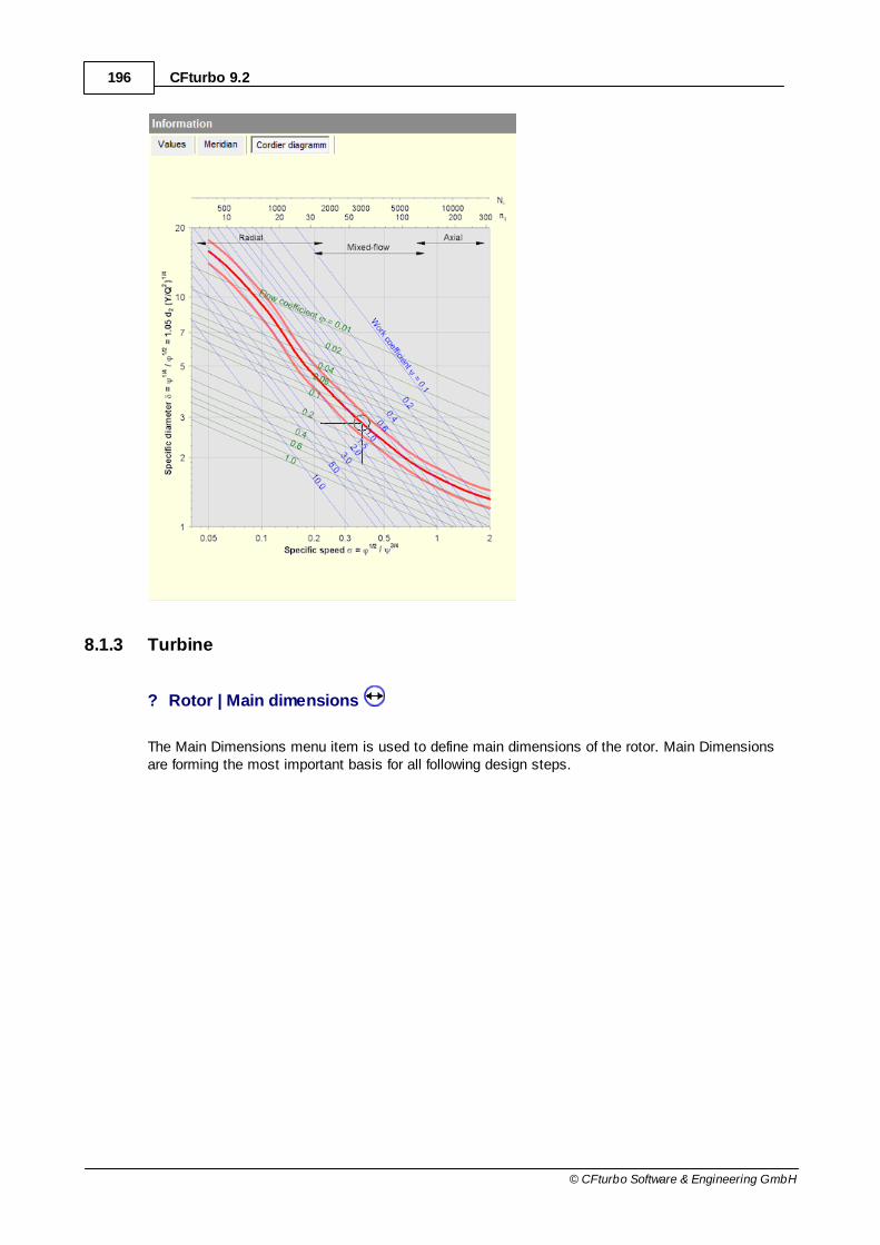
196 CFturbo 9.2
© CFturbo Software & Engineering GmbH
8.1.3 Turbine
? Rotor | Main dimensions
The Main Dimensions menu item is used to define main dimensions of the rotor. Main Dimensionsare forming the most important basis for all following design steps.

197Impeller
© CFturbo Software & Engineering GmbH
The real flow in a turbine rotor is turbulent and three-dimensional. Secondary flows, separation and reattachment inboundary layers, transient recirculation areas and otherfeatures may occur. Nevertheless it is useful - and it iscommon practice in the turbine design theory - to simplify therealistic flow applying representative streamlines for the firstdesign approach.
Employing 1D-streamline theory the following cross sectionsare significant in particular: area just before leading edge(index 0), at the beginning (index 1) and at the end of theblade (index 2) and finally behind the trailing edge (index 3).
The cross section (S) is situated at the suction side in theconnection flange of the component following the turbine.
Details
Setup
Assumptions
Dimensions
The design of the main dimensions has to be made in a strict order. This will be secured by thefollowing:One step within the design has to be finished completely before the next can beaccomplished. That is to say, the changeability of a tab sheet will be disabled by CFturbo until allnecessary parameters have been specified.
198
199
199

198 CFturbo 9.2
© CFturbo Software & Engineering GmbH
8.1.3.1 Setup
On page Setup you can specify some basic settings.
On panel General you can select:
Manual dimensioningIn manual dimensioning mode the main dimensions and blade angles are not calculated byCFturbo. All these values are user-defined input values.
Splitter bladesDesign impeller with or without splitter blades.
UnshroudedDesign a shrouded (closed) or unshrouded (open) impeller.For an unshrouded impeller you have to define the tip clearance.
When creating a new design the initial default settings for some important properties are displayed inthe panel Initial default settings. These settings are used in further design steps and can bemodified by selecting the Change settings button. Of course these default settings can be modifiedmanually in the appropriate design steps. See Preferences: Impeller/ Stator settings for moreinformation.
The design concept is based on a mean flow area, therefore a mean blade angle bB1 as well as amean incidence angle i has to be given. In order to yield best efficiency the angle of incidence should
139

199Impeller
© CFturbo Software & Engineering GmbH
be 20..30°.
Some design point values are displayed in the right Information panel when selecting the pageValues (see Global setup ).
8.1.3.2 Parameters
On page Parameters you have to put in or to modify parameters resulting from approximationfunctions in dependence on specific speed nq (see Approximation functions ).
For details of how to handle the parameter edit fields please see Edit fields with empirical functions.
Parameters
58
124
41
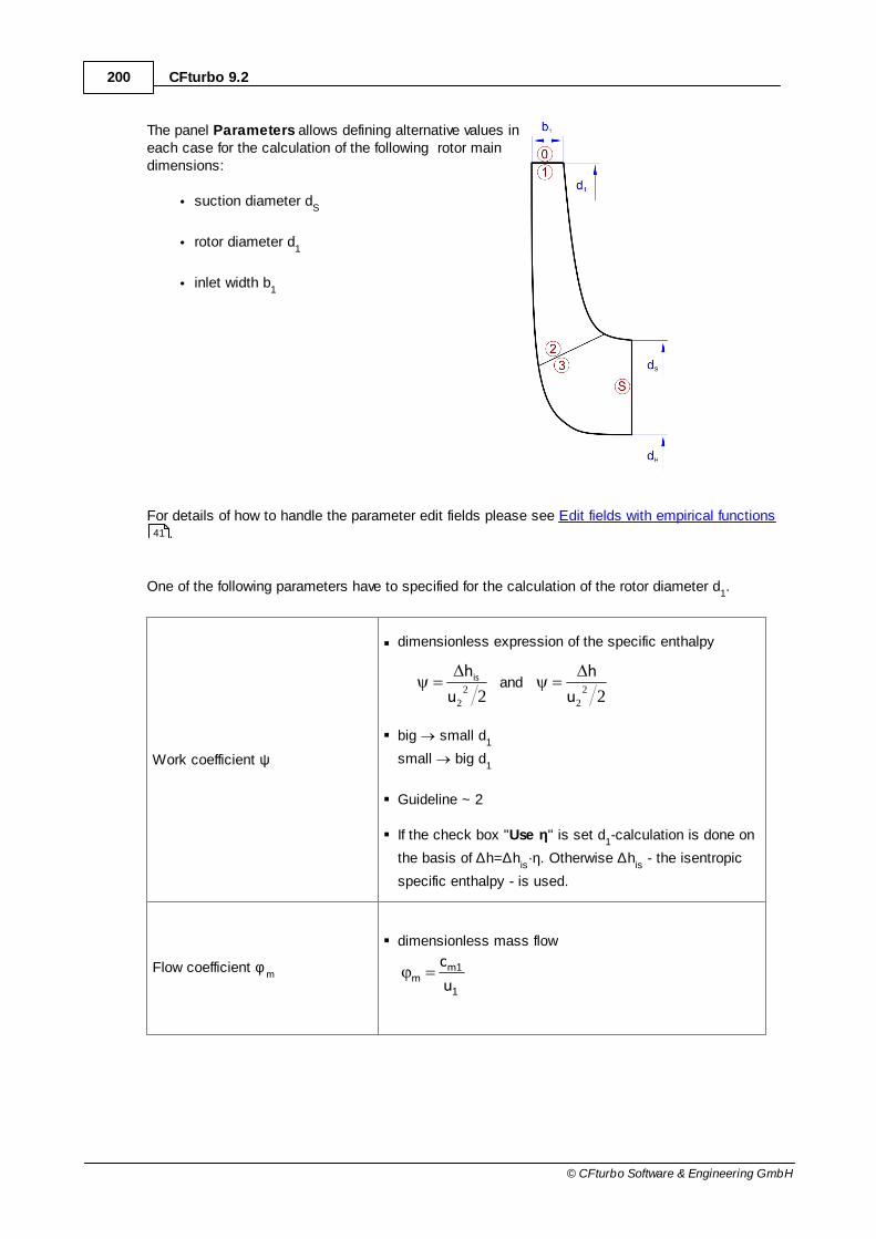
200 CFturbo 9.2
© CFturbo Software & Engineering GmbH
The panel Parameters allows defining alternative values ineach case for the calculation of the following rotor maindimensions:
suction diameter dS
rotor diameter d1
inlet width b1
For details of how to handle the parameter edit fields please see Edit fields with empirical functions.
One of the following parameters have to specified for the calculation of the rotor diameter d1.
Work coefficient ψ
dimensionless expression of the specific enthalpy
222
2
2
2 u
h
u
his and
big small d1
small big d1
Guideline ~ 2
If the check box "Use η" is set d1-calculation is done on
the basis of ∆h=∆his·η. Otherwise ∆h
is - the isentropic
specific enthalpy - is used.
Flow coefficient φm
dimensionless mass flow
1
1mm
u
c
41

201Impeller
© CFturbo Software & Engineering GmbH
in accordance to Cordier-Diagramm
Tangential force coefficient
ct = ψ /φ
m
Coefficient of a flow force pointing in tangential direction
3 ... 4 Francis high-speed turbine4 ... 8 Normal-speed turbine8 ...10 Low-speed turbine
Coefficient ratio
cR
= ψ /φm
2
Ratio of work to the square of the meridional speed
6 ...10 Francis high-speed turbine10...12 Normal-speed turbine12...30 Low-speed turbine
Between the work coefficient ψ the relative flow angle 1 and the tangential force coefficient ψ /φm
there is the following relation:
1cot/
1
2
1
1
m
At a relative flow angle of 1= 90° the work coefficient becomes ψ =2. In this case the work
coefficient should not be chosen as a design parameter in the tab sheet Parameters. Otherwiseone has no influence on the meridional flow coefficient and therefore meridional flow, see lastequation.
For all further geometric variables guess values have to be given:
Diameter ratio d2/d
1 ~0.5
Meridional accelerationc
m2/c
m1 1.005..1.05
Meridional acceleration (suctionside) c
mS/c
m2
or
Diameter ratio dS/d
1
1.005..1.05
~0.7
Diameter ratio dN/d
S ~0.3
208
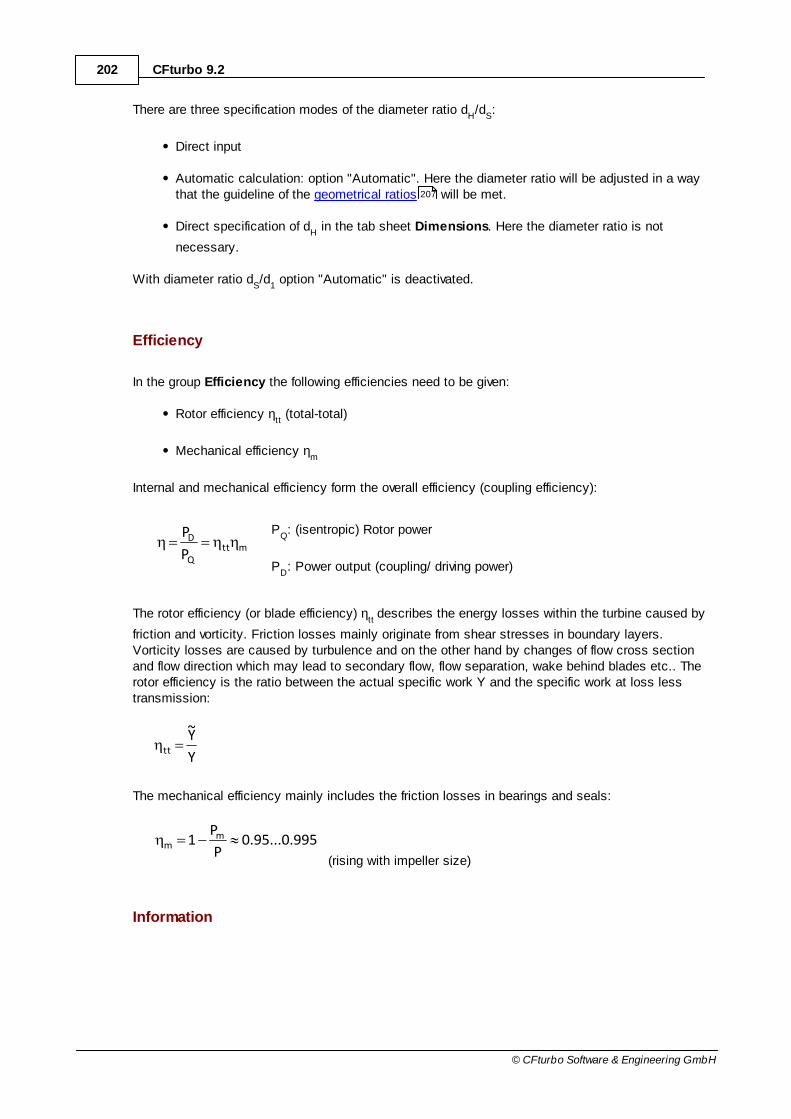
202 CFturbo 9.2
© CFturbo Software & Engineering GmbH
There are three specification modes of the diameter ratio dH/d
S:
Direct input
Automatic calculation: option "Automatic". Here the diameter ratio will be adjusted in a waythat the guideline of the geometrical ratios will be met.
Direct specification of dH in the tab sheet Dimensions. Here the diameter ratio is not
necessary.
With diameter ratio dS/d
1 option "Automatic" is deactivated.
Efficiency
In the group Efficiency the following efficiencies need to be given:
Rotor efficiency ηtt (total-total)
Mechanical efficiency ηm
Internal and mechanical efficiency form the overall efficiency (coupling efficiency):
mttQ
D
P
P PQ: (isentropic) Rotor power
PD: Power output (coupling/ driving power)
The rotor efficiency (or blade efficiency) ηtt
describes the energy losses within the turbine caused by
friction and vorticity. Friction losses mainly originate from shear stresses in boundary layers.Vorticity losses are caused by turbulence and on the other hand by changes of flow cross sectionand flow direction which may lead to secondary flow, flow separation, wake behind blades etc.. Therotor efficiency is the ratio between the actual specific work Y and the specific work at loss lesstransmission:
Y
Y~
tt
The mechanical efficiency mainly includes the friction losses in bearings and seals:
995.0...95.0P
P1 m
m
(rising with impeller size)
Information
207

203Impeller
© CFturbo Software & Engineering GmbH
In the right panel of the tab sheet Parameter some variables are displayed for Information:
actual Power PD
PD = P
Q·η
tt
Power loss PL
PL = P
Q - P
D
Flow Q
calculated with total density in the outlet:
2t
mQ
Total pressure inlet pt1
pt1
= pt2
Pressure ratio total-total tt
Pressure ratio total-static ts
Efficiency total-total tt
Efficiency total-static ts
Velocity ratioY2
u1ts
In general for cost reasons single-stage & single-intake machines are preferred covering a range ofabout 10 < nq < 400. In exceptional cases it may become necessary to design a rotor for extremelylow specific speed values (nq < 10). These rotors are characterized by large rotor diameters and lowrotor widths. The ratio of free flow cross section area to wetted surfaces becomes unfavorable and iscausing high frictional losses. To prevent this one may increase either rotational speed n or massflow rate m if possible. An alternative solution could be the design of a multi-stage turbine reducingthe pressure drop of a single-stage. If especially high specific speed values (nq > 400) do occur onecan reduce rotational speed n or mass flow rate m if feasible. Another option would be to operateseveral single-stage turbines - having a lower nq - in parallel.
Please note: CFturbo® is preferably used between 10 < nq < 150 – radial and mixed-flow rotors.
8.1.3.3 Dimensions
In the panel Shaft, the required shaft diameter is computed.
Shaft/ Hub 209

204 CFturbo 9.2
© CFturbo Software & Engineering GmbH
The hub diameter has to be determined in the panel Main dimensions.
The main dimensions of a designed rotor - suctiondiameter d
S, impeller diameter d
1, outlet width b
1 -
can be seen on the tab sheet Dimensions. They canbe recomputed by pressing the Calculate-buttonwithin the panel Main dimensions. The computationis based on "Euler's Equation of Turbomachinery", onthe continuity equation and the relations for thevelocity triangles as well as on the parameters andparameter ratios given in the tab sheets DesignPoint and Parameters.
One may accept the proposed values or can modifythem slightly, e.g. to meet a certain normalizeddiameter.
In case the checkbox Automatic is activated a new calculation will accomplished after any changeof parameter. Then the manual alteration of the main dimensions is not possible.
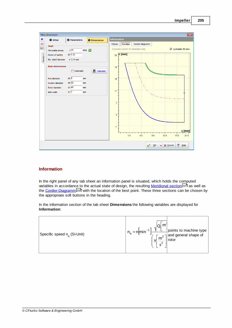
205Impeller
© CFturbo Software & Engineering GmbH
Information
In the right panel of any tab sheet an information panel is situated, which holds the computedvariables in accordance to the actual state of design, the resulting Meridional section as well asthe Cordier-Diagramm with the location of the best point. These three sections can be chosen bythe appropriate soft buttons in the heading.
In the information section of the tab sheet Dimensions the following variables are displayed forInformation:
Specific speed nq (SI-Unit)
43
2
2
3
1q
g
1
s
mY
smQ
minnn points to machine typeand general shape ofrotor
207
208

206 CFturbo 9.2
© CFturbo Software & Engineering GmbH
Specific speed NS(US-Unit)
q4
3
2
2S n531.51
g
1
s
ftY
gpmQrpmnN
„Type number“ s (ISO 2548)
9.52
n
Y
Qn2 q
43S
Speed coefficient 8.157
n
Y
Qn1078.2 q
43
Guideline: 0.16..0.32.This has to be matchedwith the design.
Work coefficient 21
tt
u
Y2
Inlet pressure, density and temperature p1, T
1, ρ
1, p
t1, T
t1, ρ
t1 static and total values
Inlet velocities c1, c
u1, c
m1, w
1
Peripheral speed at inlettt
1Y2
u
Machine-Mach-number1
11
a
uM
Blade width at inlet*1
b
Outlet pressure, density and temperature p2, T
2, ρ
2, p
t2, T
t2, ρ
t2 static and total values
Outlet velocities c2, c
u2, c
m2, w
2
Peripheral speed at outlet ndu 22
Outlet Ma-Number2
22
a
cM

207Impeller
© CFturbo Software & Engineering GmbH
Mean diameter at outlet 11
22 d
d
dd
Width at outlet22m2
2cd
m025.1b
Ratio Width-diameter at inlet b1/d
1 guideline: 0.05..0.15
Diameter ratio
d2/d
2min with:
2N
2Smin2 dd
2
1d
guideline: 1.005..1.05
Ratio radius-width at outlet2
NS
2
NS
b2
dd
b
rrguideline: 1.005..1.05
The guidelines given in the last column of the last three rows, should be matched within the design.
The Meridional preview is based on the main dimensions designed until this point.

208 CFturbo 9.2
© CFturbo Software & Engineering GmbH
The Cordier diagram is based on an intensive empirical analysis of proved turbomachinery usingextensive experimental data.

209Impeller
© CFturbo Software & Engineering GmbH
8.1.4 Shaft/Hub
Dimensioning of the shaft diameter is made under application of strength requirements. It is a resultof torque M=P/ω to be transmitted by the shaft and the allowable torsional stress of the material.
You can directly enter allowable stress or select the value from a list by pressing button rightbeside the input area.

210 CFturbo 9.2
© CFturbo Software & Engineering GmbH
In a small dialog window you can see somematerials and its allowable stress. The list can
be extended or reduced by and button.You can confirm selected value by pressingthe OK-button.
At File location the file containing materialproperties is shown. The file is originally called Stress.cftst and is located in the installationdirectory of CFturbo. Modifications of the listwill be saved if the user is leaving the dialogwindow by clicking the OK-button. In casethere are no write permissions the user canchoose another directory to save the file.Renaming of files is possible by Save as-functionality. By clicking the Open-button apreviously saved file can be opened.
To consider a higher load, e.g. due to operating conditions away from the design point, a safetyfactor SF may be specified leading to a modified proposed shaft diameter d.
32n
SFQY8d
The hub diameter dH is usually selected as small as possible and depends on the kind of connection
of hub and shaft.
8.2 Meridional contour
? Impeller | Meridional contour
The design of the meridional contour is the second important step to design the impeller.
Graphical elements can be manipulated not only by the computer mouse per drag and drop but alsoby using context menus. To this end a right click on the appropriate element is necessary. Doing sothe mode of the leading edge can be changed as well as the coordinates of Bezier points for

211Impeller
© CFturbo Software & Engineering GmbH
example.
Design Mode
There are two different options to define hub and shroud contours.
Hub, Shroud Direct design of the two contours
Middle Design of center line; the contours result from given cross sectiondistribution between suction (dS) and outlet (d2) cross sections
In the first case hub and shroud can be designed separately or in the coupled mode. If you hit the Hub-Shroud Coupled check box hub and shroud will be modified simultaneously considering thesame relative positions of the Bezier points.
In the second case only the geometric center line of the flow channel will be modified. The contoursresult in specifying a cross section distribution. It may either be linear or could be loaded from a file.
# cross section distribution# start/end tangential,# midsection linear
On the left side you can see an example of cmprogression.

212 CFturbo 9.2
© CFturbo Software & Engineering GmbH
# (spline interpolation 9points)0.00 0.000000.04 0.017280.08 0.038300.12 0.063680.16 0.094040.20 0.130000.24 0.171640.28 0.216870.32 0.263140.36 0.310180.40 0.360000.44 0.414040.48 0.471020.52 0.528980.56 0.585960.60 0.640000.64 0.689820.68 0.736860.72 0.783130.76 0.828360.80 0.870000.84 0.905960.88 0.936320.92 0.961700.96 0.982721.00 1.00000
All lines starting with a # symbol are comments. Allother lines contain the numerical values. The firstvalue of each line is the relative meridionalcoordinate x along the center line, with x=0 at theinlet cross-section and x=1 at the outlet cross-section. The second value is the relative crosssection A
rel, which allows to compute the related
absolute value:
inoutrelin AAAAA
The cross section is used to determine the width bvertical to the flow direction.
This strategy is mainly capable for mixed-flowimpellers, it's suboptimal for radial impellers withrelative sharp direction change from axial to radial.
Trailing edge fixed on ...
The trailing edge (turbines: leading edge) is fixed on meridional outlet (turbines: inlet) and can notdesigned like the leading edge (turbines: trailing edge ).
Uncheck this option to detach the trailing edge (turbines: leading edge) from meridional outlet(turbines: inlet) and design its position and shape independently.
Display Options
In the Display Options panel some graphical representations can be activated for illustration:
226 226

213Impeller
© CFturbo Software & Engineering GmbH
Area circles
for calculation of cross section area
Neighboring components
on inlet and outlet side are displayed forinformation.
Use the buttons to zoom the current meridionalshape only or the entire geometry.
Meridional flow/ Grid
grid used for meridional flow calculation
see Meridional flow calculation 230

214 CFturbo 9.2
© CFturbo Software & Engineering GmbH
Meridional flow/ Streamlines
meridional streamlines, equal mass flowfraction between neighboring streamlines
see Meridional flow calculation
Meridional flow/ cm lines
iso lines of const. meridional velocity cm
see Meridional flow calculation
Meridional flow/ cm surfaces
iso surfaces of const. meridional velocity cm
(scaling is displayed below the diagram)
see Meridional flow calculation
230
230
230
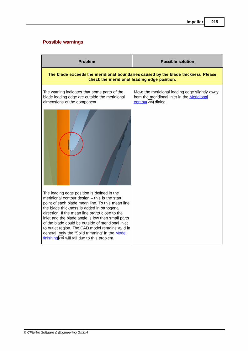
215Impeller
© CFturbo Software & Engineering GmbH
Possible warnings
Problem Possible solution
The blade exceeds the meridional boundaries caused by the blade thickness. Pleasecheck the meridional leading edge position.
The warning indicates that some parts of theblade leading edge are outside the meridionaldimensions of the component.
The leading edge position is defined in themeridional contour design – this is the startpoint of each blade mean line. To this mean linethe blade thickness is added in orthogonaldirection. If the mean line starts close to theinlet and the blade angle is low then small partsof the blade could be outside of meridional inletto outlet region. The CAD model remains valid ingeneral, only the “Solid trimming” in the Modelfinishing will fail due to this problem.
Move the meridional leading edge slightly awayfrom the meridional inlet in the Meridionalcontour dialog.
290
210

216 CFturbo 9.2
© CFturbo Software & Engineering GmbH
8.2.1 Hub-Shroud contour
Hub & Shroud
Hub and shroud countours can be designed as:
Bezier curveThe curve is defined by the position of the Bezier points.
Details
Circular Arc + Straight lineThe curve consists of a circular arc and a straight line.
Details
Straight lineThe contour is defined by a straight line between start and endpoint.
218
222

217Impeller
© CFturbo Software & Engineering GmbH
PolylineThe curve is fixed and cannot be modified interactively. Import of point sets from file ispossible (Load polyline).
Radial ventilator impellers are designed simply by arc and line by default (Circular Arc + Straightline), all other impeller types in Bezier mode (Bezier curve).
Special context menu features
On the endpoints of hub and shroud the complete geometry can be shifted optionally (Shiftcomplete geometry). Hence the geometry can be positioned on a specific axial position.
There are some reasonable constraints when working in this simplified mode e.g. theinclination angle of the trailing edge can only be set when hub and shroud are in Bezier mode
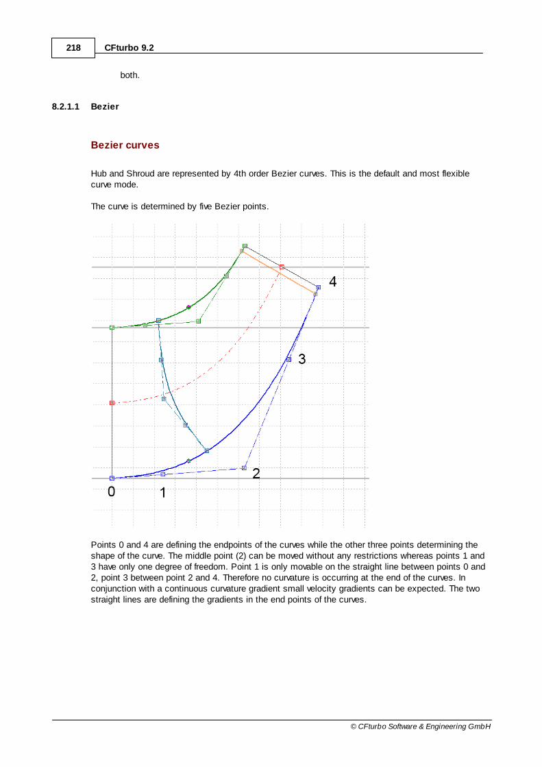
218 CFturbo 9.2
© CFturbo Software & Engineering GmbH
both.
8.2.1.1 Bezier
Bezier curves
Hub and Shroud are represented by 4th order Bezier curves. This is the default and most flexiblecurve mode.
The curve is determined by five Bezier points.
Points 0 and 4 are defining the endpoints of the curves while the other three points determining theshape of the curve. The middle point (2) can be moved without any restrictions whereas points 1 and3 have only one degree of freedom. Point 1 is only movable on the straight line between points 0 and2, point 3 between point 2 and 4. Therefore no curvature is occurring at the end of the curves. Inconjunction with a continuous curvature gradient small velocity gradients can be expected. The twostraight lines are defining the gradients in the end points of the curves.
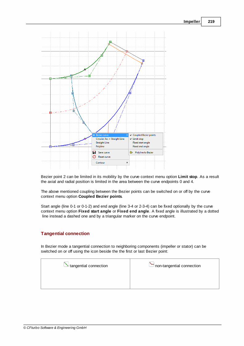
219Impeller
© CFturbo Software & Engineering GmbH
Bezier point 2 can be limited in its mobility by the curve context menu option Limit stop. As a resultthe axial and radial position is limited in the area between the curve endpoints 0 and 4.
The above mentioned coupling between the Bezier points can be switched on or off by the curvecontext menu option Coupled Bezier points.
Start angle (line 0-1 or 0-1-2) and end angle (line 3-4 or 2-3-4) can be fixed optionally by the curvecontext menu option Fixed start angle or Fixed end angle. A fixed angle is illustrated by a dotted line instead a dashed one and by a triangular marker on the curve endpoint.
Tangential connection
In Bezier mode a tangential connection to neighboring components (impeller or stator) can beswitched on or off using the icon beside the the first or last Bezier point:
tangential connection non-tangential connection

220 CFturbo 9.2
© CFturbo Software & Engineering GmbH
The hint of the icon contains the angle of the neighboringcomponent for information.
Primary design
For an automatic primary design of the contours the following values are used:
Main dimensions : dH, d
S, d
2, b
2
Inclination angle g of trailing edge to horizontal (see Approximation functions )
Inclination angle e of hub and shroud to vertical (see Approximation functions )
Axial extension: pumps, ventilators according to a) (Guelich), turbines according to b)(Lindner), compressor according to c) (Aungier). In some cases where the hub diameter d
H is
quite small compared to the impeller diameter d2, for compressors the average of a) and b) is
applied instead of c).
cos2b74nddz)a 207.1
qSa2
166
124
124

221Impeller
© CFturbo Software & Engineering GmbH
2ddz)b H2/1
58.1d
d023.0014.0dz)c
H
22
Point 1 is primary placed at 3/4 of the axial distance of points 0 and 2, point 3 at 2/3 of the radialdistance of points 2 and 4.
The manipulation of the contours can be achieved by shifting the positions of the Bezier points. Asan alternative the position of Bezier points can be realized by input of numerical values (see Graphical dialogs ). Trailing edge can be rotated by moving Bezier points 4. If <Ctrl> key ispressed simultaneously the whole trailing edge can be moved in axial direction with constantinclination angle (change axial extension). Inclination angle of trailing edge can be numericallydetermined by clicking the right mouse button on it.
In the design process for the meridional contours the user should try to create curvatures which areas steady as possible in order to minimize local decelerations. The maximum values of the curvatureshould be as low as possible and should entirely disappear at the end of the contours. Theserequirements are met very well by Bezier curves showing the above mentioned limitations. Localcross section 2π rb should grow from the suction to the impeller diameter as uniformly as possible.
8.2.1.1.1 Converting Polyline / Bezier
If using simple polyline for hub and/or shroud - e.g.for imported meridional geometrie - this curve canbe converted to a Bezier curve. Thus, it's possibleto make systematic modifications of existinggeometries.
39
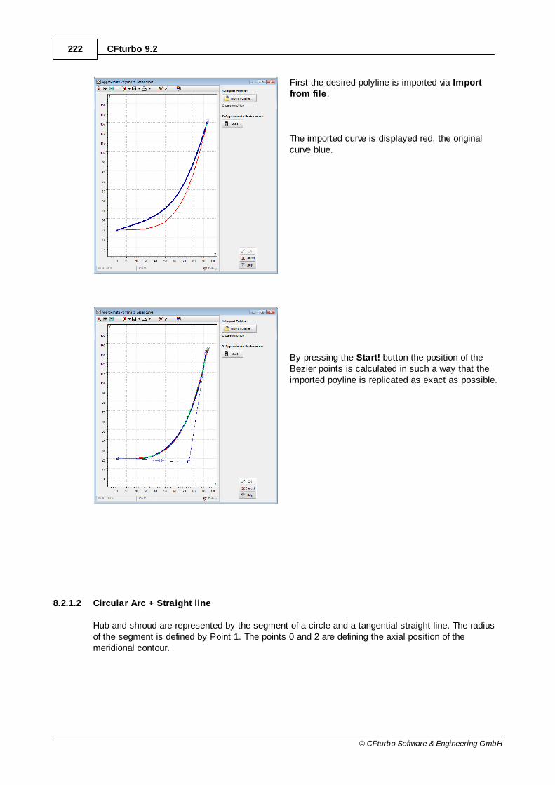
222 CFturbo 9.2
© CFturbo Software & Engineering GmbH
First the desired polyline is imported via Importfrom file.
The imported curve is displayed red, the originalcurve blue.
By pressing the Start! button the position of theBezier points is calculated in such a way that theimported poyline is replicated as exact as possible.
8.2.1.2 Circular Arc + Straight line
Hub and shroud are represented by the segment of a circle and a tangential straight line. The radiusof the segment is defined by Point 1. The points 0 and 2 are defining the axial position of themeridional contour.
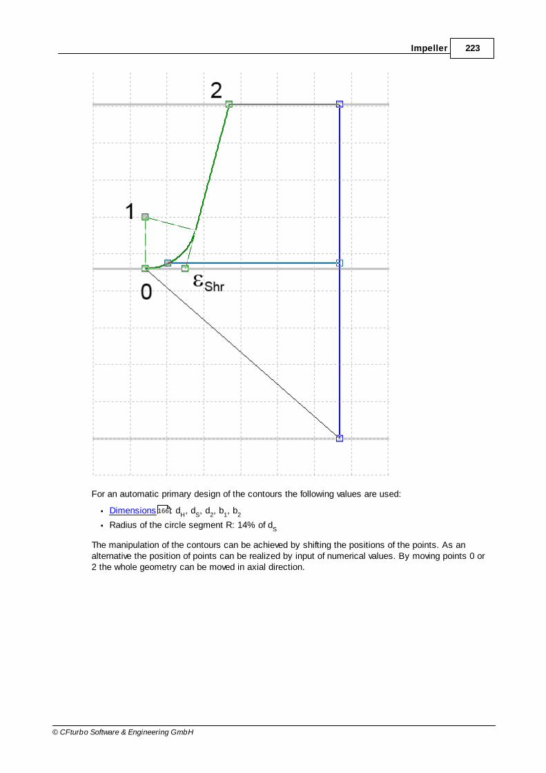
223Impeller
© CFturbo Software & Engineering GmbH
For an automatic primary design of the contours the following values are used:
Dimensions : dH, d
S, d
2, b
1, b
2
Radius of the circle segment R: 14% of dS
The manipulation of the contours can be achieved by shifting the positions of the points. As analternative the position of points can be realized by input of numerical values. By moving points 0 or2 the whole geometry can be moved in axial direction.
166
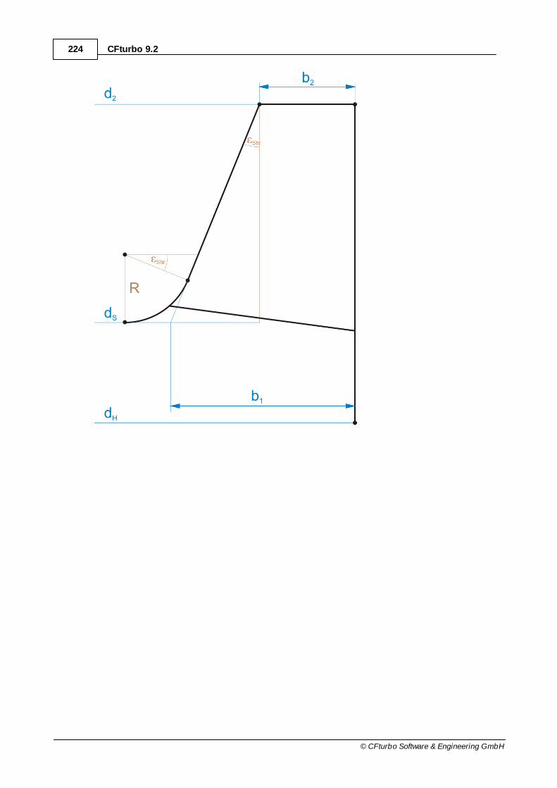
224 CFturbo 9.2
© CFturbo Software & Engineering GmbH
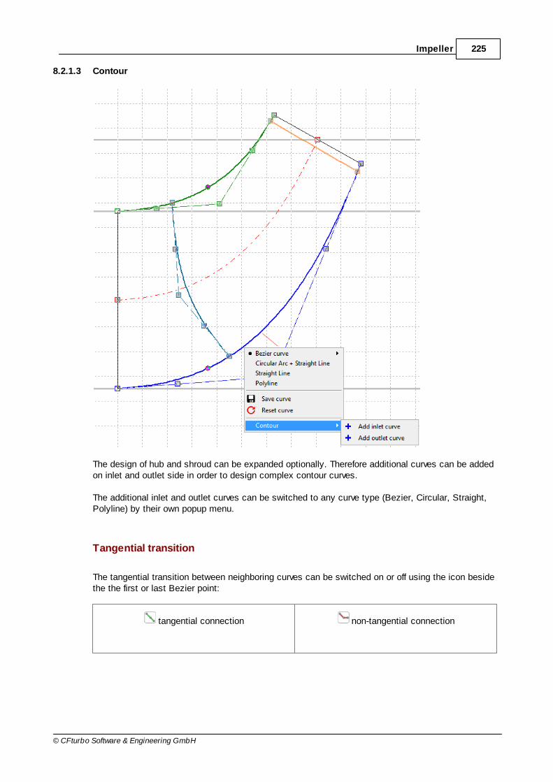
225Impeller
© CFturbo Software & Engineering GmbH
8.2.1.3 Contour
The design of hub and shroud can be expanded optionally. Therefore additional curves can be addedon inlet and outlet side in order to design complex contour curves.
The additional inlet and outlet curves can be switched to any curve type (Bezier, Circular, Straight,Polyline) by their own popup menu.
Tangential transition
The tangential transition between neighboring curves can be switched on or off using the icon besidethe the first or last Bezier point:
tangential connection non-tangential connection
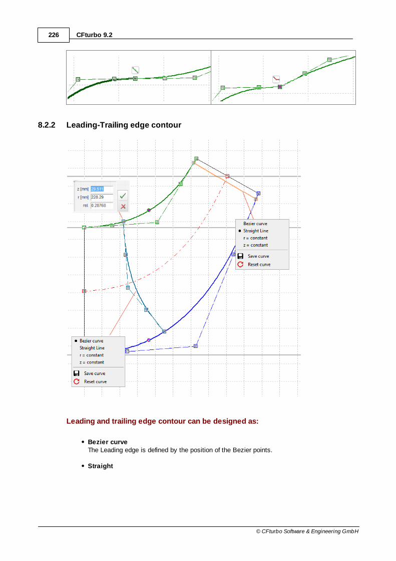
226 CFturbo 9.2
© CFturbo Software & Engineering GmbH
8.2.2 Leading-Trailing edge contour
Leading and trailing edge contour can be designed as:
Bezier curveThe Leading edge is defined by the position of the Bezier points.
Straight

227Impeller
© CFturbo Software & Engineering GmbH
The Leading edge is a straight connecting line between the endpoints on hub and shroud.
r = constantThe Leading edge runs on constant radius, i.e. parallel to rotational axis.
z = constantThe Leading edge runs on constant axial coordinate, i.e. perpendicular to rotational axis.
The trailing edge can not be designed, if Trailing edge fixed on outlet .
The position of the meridional blade leading edge on hub and shroud can be defined by its axial (z),radial (r) or relative position (rel.) optionally.
In case of Splitter blades each leading edge can be designed individually.
The turbine rotors and compressor impellers have straight leading edges by default, in case ofturbines z = constant additionally.
212

228 CFturbo 9.2
© CFturbo Software & Engineering GmbH
The leading edge is designed by a 4th order Bezier curve, too. Regarding the Bezier points, thestatements made above are applicable in a similar way. The only difference is the manipulation ofthe end points. For the leading edge there is no restriction on hub and shroud contour. The positionof the leading edge always appears at the same relative position in a primary CFturbo design but thisnot mean to be a suggestion.
Leading edge can be designed as a straight line by selecting Straight in the context menu of thecurve (controlled by 2 Bezier points). Additionally the edge can be strictly axial or radial (z = const.or r = const, controlled by 1 Bezier point).
For radial impellers having nq 10…30 the leading edge is often designed parallel to the z-axis. Asthe trailing edge is parallel to the axis too for such applications 2D-curved blades can be created. Athigher specific speed nq or due to strength reasons the leading edge often is extended into theimpeller suction area. Various diameters result in different leading edge blade angles - therefore 3D-curved blades are created. This leads to better performance curves, higher efficiencies and improvedsuction capacity for pumps.
The position of the leading edge should be chosen in a way that the energy transmission should beabout equal on all meridional flow surfaces. A criterion is the approximately equal static momentS = r dx of the meridional streamlines on hub and shroud between leading and trailing edge. In theStatic moment section the corresponding numerical values are displayed. Both ends of the leadingedge should be perpendicular to the meridional contours of hub and shroud if possible. To obtainequal static moments on hub and shroud the trailing edge is often not parallel to axial direction -particularly at higher specific speeds (mixed-flow impellers).
8.2.3 Additional views
The following informationcan be displayed in themeridional contour dialogusing the "Additional views"button:
Informational values
Some additional values are displayed for information:
Minimal curvature radius on hub and shroud (position is marked on the hub and shroud curves)
Static moment S from leading to trailing edge on hub and shroud (see below)

229Impeller
© CFturbo Software & Engineering GmbH
Angle ε in the hub and shroud end points measured to the horizontal direction
Angle γLE
of leading edge on hub and shroud measured to the horizontal direction
Axial extension ∆z of hub and shroud
Radial extension ∆r of hub and shroud
Angle γTE
of trailing edge measured to the horizontal direction
Default axial extension ∆zD from inlet shroud to outlet midline (defined for radial impellers only)
Maximal axial extension ∆zM of complete meridional shape
Maximal radial extension ∆rM of complete meridional shape
Axial blade overlapping zB of shroud blade area onto hub blade area in z-direction
LE distance b1 from LE at hub to LE at shroud
LE circle b1 as diameter of a circle inside the meridional contour at LE position
LE diameter d1 at intersection of LE and midline
Diameter ratio d1/d
2
3D-Preview
3D model of the currently designed meridional shape.
The meridian contains hub and shroud as well as acircular projection of the blade in a plane.
150

230 CFturbo 9.2
© CFturbo Software & Engineering GmbH
Curvature progression
Curvature progression along hub and shroud curve. The progression should be as smooth aspossible avoiding hard peaks.
Static moment
The static moment is the integral of the curve length (x) in the blade area multiplied by the radius (r):
TE
LE
r
r
rdxS
It should be similar for hub and shroud end points.
Area section
Progression of the cross section area between hub and shroud.
Local maximum or minimum should be avoided.
Cm progression
Progression of the meridional velocity cm
along the meridional streamlines.
see Meridional flow calculation
8.2.4 Meridional flow calculation
Stream function ψ
Within the meridian the stream function ψ will be solved. For an incompressible fluid this equation isin cylindrical co-ordinates (z, r):
0rr
1
rz 2
2
2
2
For a compressible fluid the equation looks like:
230

231Impeller
© CFturbo Software & Engineering GmbH
,0rr
1
zza
2
rra
11
zza
11
22
22
22
22
2
where a is the sonic speed defined by:
TZRa
Hub and shroud are representing stream lines where as at in and outlet there is a certain streamfunction distribution chosen. This is done in accordance to the mass flow imposed by the globalsetup .
Calculation grid and solution scheme
The equation is solved using a finite-difference-method (FDM) on a computational grid, which will begenerated using an elliptic grid generation. For more information about the used computationaltechniques refer to e.g. Anderson et al .
Results
The meridional velocity component can be calculated by the axial velocity component:
,rr
rc RR
z
by the radial velocity component:
,zr
rc RR
r
with:
.ccc 2r
2zm
rR and ρ
R are reference radius and density respectively. In case of incompressible fluids the density
is constant throughout the flow domain and the according term in the equations is discarded.
Example
After each change of the meridional contour a new computational grid is calculated. Also, someextensions are added to the inlet and outlet in order to ease the setup of the boundary conditions.
58
355

232 CFturbo 9.2
© CFturbo Software & Engineering GmbH
On the basis of the updated grid the equation for stream function is solved and lines with constantvalues of the stream function and of the meridional velocity are displayed.
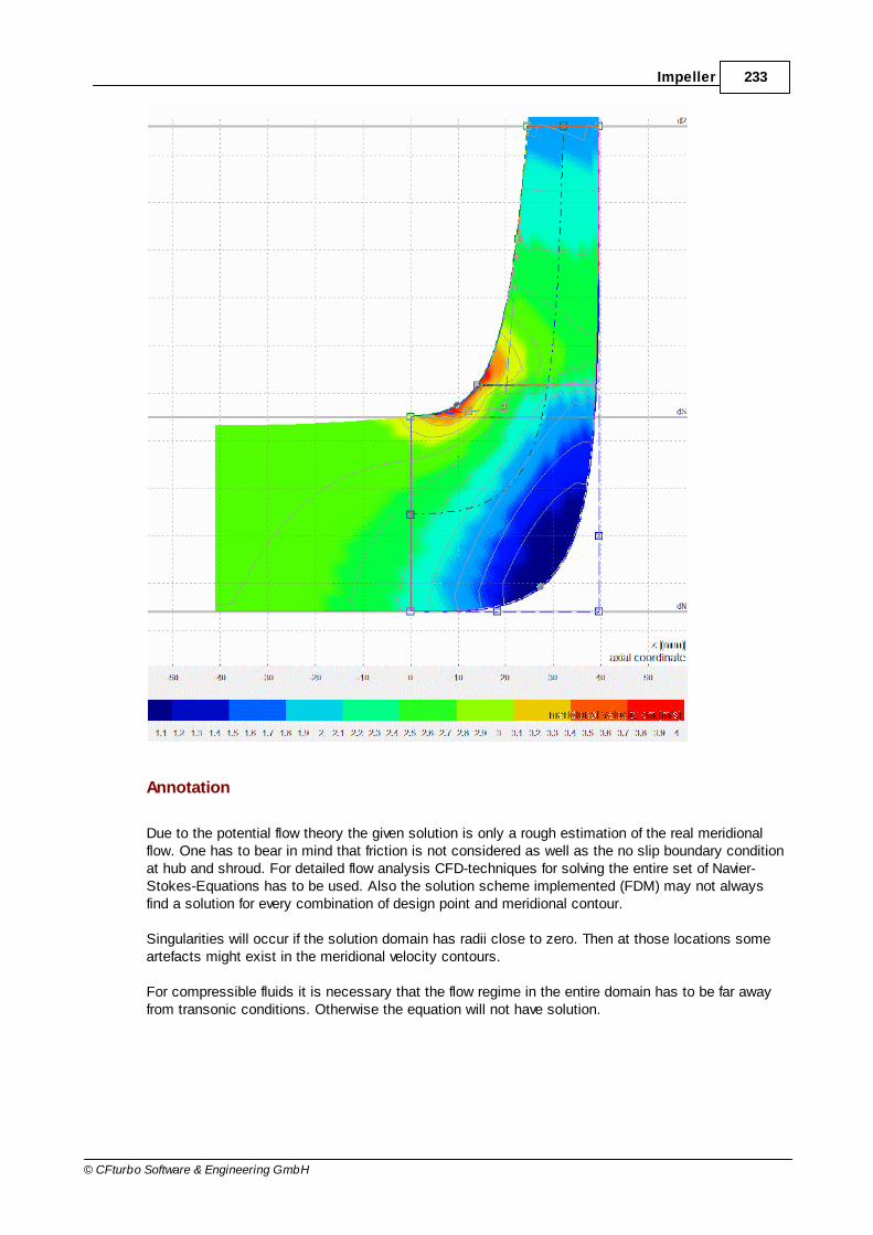
233Impeller
© CFturbo Software & Engineering GmbH
Annotation
Due to the potential flow theory the given solution is only a rough estimation of the real meridionalflow. One has to bear in mind that friction is not considered as well as the no slip boundary conditionat hub and shroud. For detailed flow analysis CFD-techniques for solving the entire set of Navier-Stokes-Equations has to be used. Also the solution scheme implemented (FDM) may not alwaysfind a solution for every combination of design point and meridional contour.
Singularities will occur if the solution domain has radii close to zero. Then at those locations someartefacts might exist in the meridional velocity contours.
For compressible fluids it is necessary that the flow regime in the entire domain has to be far awayfrom transonic conditions. Otherwise the equation will not have solution.

234 CFturbo 9.2
© CFturbo Software & Engineering GmbH
8.3 Blade properties
? Impeller | Blade properties
Definition of blade properties is made in two steps:
(1) Blade setup
(2) Blade angles
Information
In the right panel some information are displayed which result from calculated or determined values:
(1) Velocity triangles
The velocity triangles of inflow and outflow are displayed.
Continuous lines represent flow velocities on hub (blue) andshroud (green).
Velocities directly before and behind blade area aredisplayed by dashed lines to show the influence of blockagein the flow domain.
Furthermore the blade angles are displayed by thick lines inorder to see the incidence angle on the leading edge and theflow deviation caused by slip velocity on trailing edge.
(2) Values
Numerical values of velocity components and flow angles aredisplayed in a table. A short description is at mouse cursortoo:
d Diameterα Angle of absolute flow to circumferential directionβ Angle of relative flow to circumferential directionu Circumferential velocityc
mMeridional velocity (c
m=w
m)
cax
Axial component of absolute velocity
cr
Radial component of absolute velocity
235
242

235Impeller
© CFturbo Software & Engineering GmbH
cu
Circumferential component of absolute velocity
c Absolute velocityw
uCircumferential component of relative velocity: w
u+c
u=u
w Relative velocityObstruction by blades (see below)
i Incidence angle: i = β1B
- β1
δ Deviation angle: δ = β2B
- β2
wR
Deceleration ratio of relative velocity: wR=w
2/w
1
(3) Default ßB
Default blade angles for the optimal Free-form 3D bladeshape is displayed compared to the currently specified/calculated angles. Deviations from default values are markedin red color. Default blade angles are calculated based on - Shockless inflow for ß
B1 at blade leading edge
- Euler equation for ßB2
at blade trailing edge
For some simplified blade shapes the blade angles of somesections result from the mean line design - see Bladeangles/ "Auto" .
If the mean line design already exists in the component thenthese dependent angles are calculated automatically forinformation, otherwise the table cells remain empty.
8.3.1 Blade setup
? Impeller | Blade properties
On tabsheet Blade setup basic blade properties are defined.
244
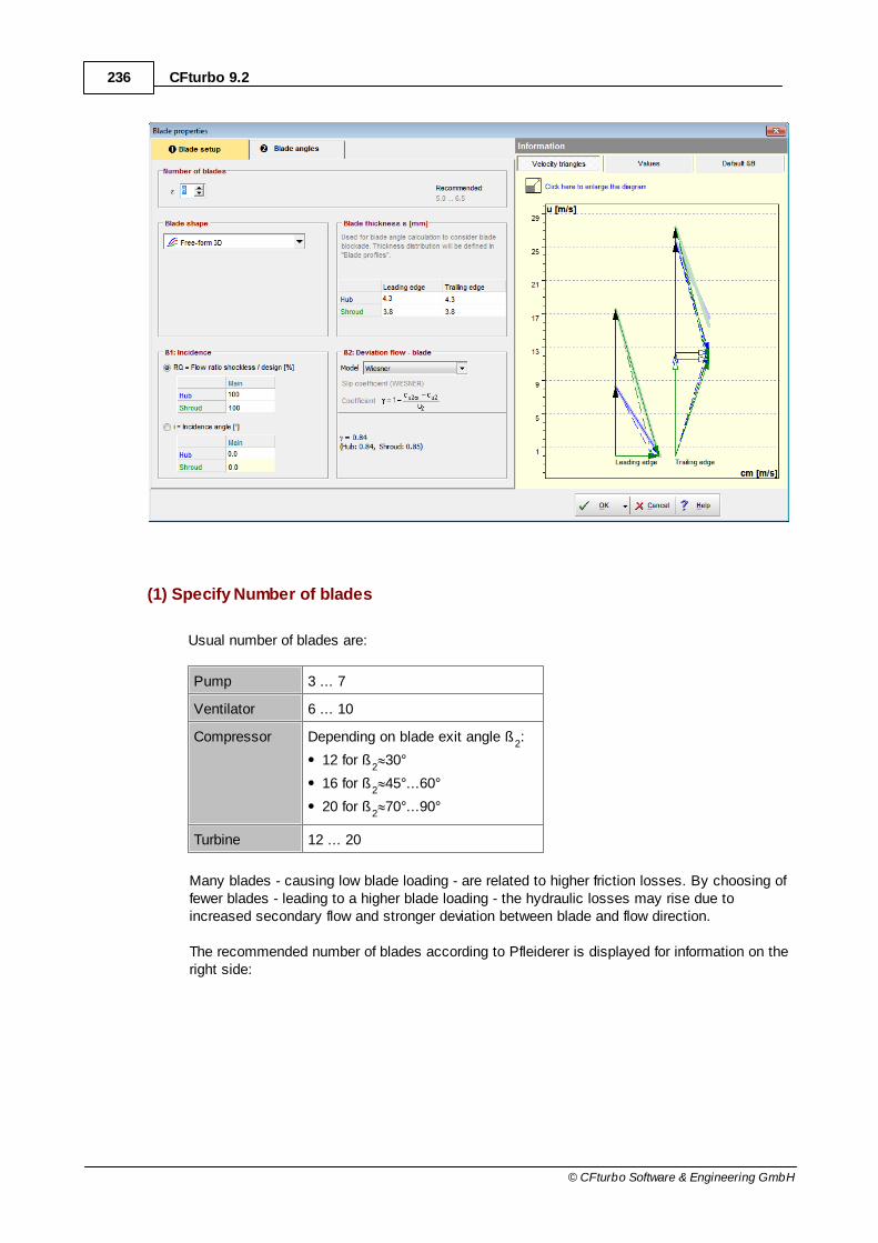
236 CFturbo 9.2
© CFturbo Software & Engineering GmbH
(1) Specify Number of blades
Usual number of blades are:
Pump 3 ... 7
Ventilator 6 ... 10
Compressor Depending on blade exit angle ß2:
12 for ß2
30°
16 for ß2
45°...60°
20 for ß2
70°...90°
Turbine 12 ... 20
Many blades - causing low blade loading - are related to higher friction losses. By choosing offewer blades - leading to a higher blade loading - the hydraulic losses may rise due toincreased secondary flow and stronger deviation between blade and flow direction.
The recommended number of blades according to Pfleiderer is displayed for information on theright side:

237Impeller
© CFturbo Software & Engineering GmbH
2sin
dd
ddkz 21
12
12z
with kz = 6.5 ... 8.0 for compressors, else 5.0 ... 6.5.
(2) Selection of desired Blade shape
There are 6 different types:
Free-form 3D Ruled surface 3D
generated by spatial movement of a straightline
Radial elements 3D(compressor and turbine only)
Free-form 2D
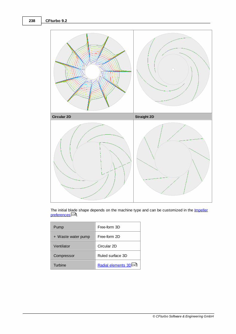
238 CFturbo 9.2
© CFturbo Software & Engineering GmbH
Circular 2D Straight 2D
The initial blade shape depends on the machine type and can be customized in the Impellerpreferences .
Pump Free-form 3D
+ Waste water pump Free-form 2D
Ventilator Circular 2D
Compressor Ruled surface 3D
Turbine Radial elements 3D
139
241
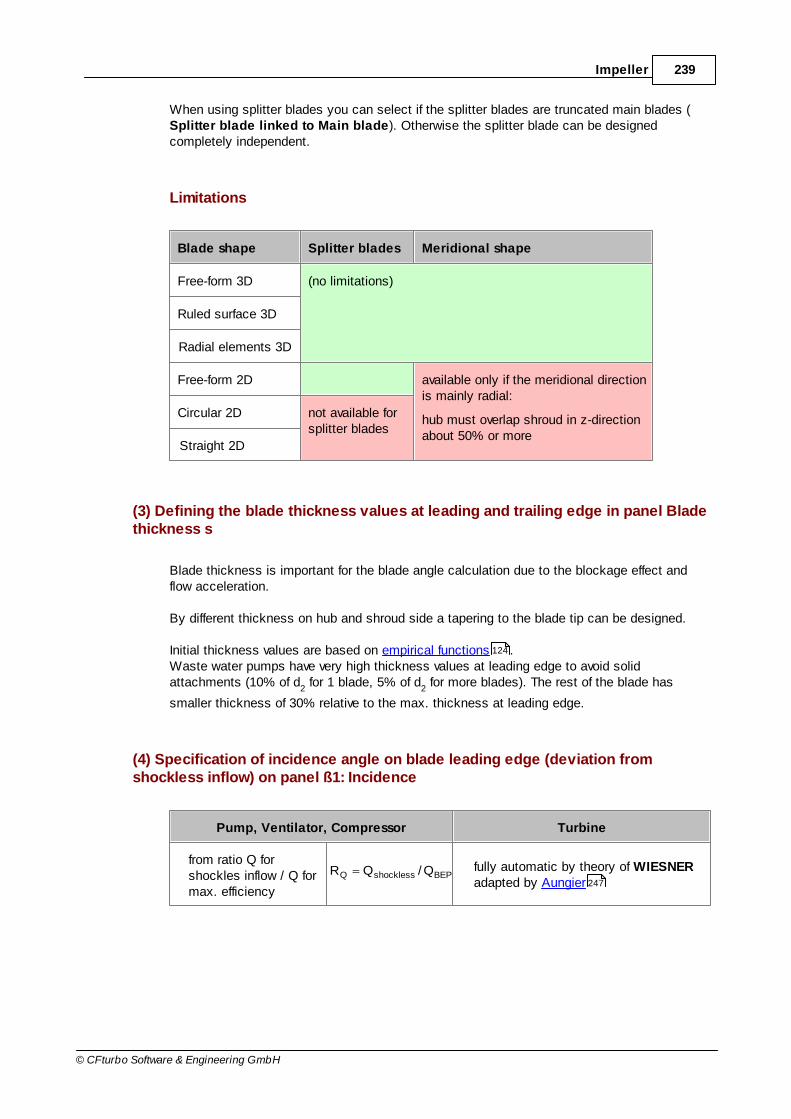
239Impeller
© CFturbo Software & Engineering GmbH
When using splitter blades you can select if the splitter blades are truncated main blades (Splitter blade linked to Main blade). Otherwise the splitter blade can be designedcompletely independent.
Limitations
Blade shape Splitter blades Meridional shape
Free-form 3D (no limitations)
Ruled surface 3D
Radial elements 3D
Free-form 2D available only if the meridional directionis mainly radial:
hub must overlap shroud in z-directionabout 50% or more
Circular 2D not available forsplitter blades
Straight 2D
(3) Defining the blade thickness values at leading and trailing edge in panel Bladethickness s
Blade thickness is important for the blade angle calculation due to the blockage effect andflow acceleration.
By different thickness on hub and shroud side a tapering to the blade tip can be designed.
Initial thickness values are based on empirical functions .Waste water pumps have very high thickness values at leading edge to avoid solidattachments (10% of d
2 for 1 blade, 5% of d
2 for more blades). The rest of the blade has
smaller thickness of 30% relative to the max. thickness at leading edge.
(4) Specification of incidence angle on blade leading edge (deviation fromshockless inflow) on panel ß1: Incidence
Pump, Ventilator, Compressor Turbine
from ratio Q forshockles inflow / Q formax. efficiency
BEPshocklessQ Q/QR fully automatic by theory of WIESNERadapted by Aungier
124
247

240 CFturbo 9.2
© CFturbo Software & Engineering GmbH
or
directly by incidence angle i
(RQ=100% or i=0° for shockless inflow)
or
directly by incidence angle i
(i=0° for shockless inflow)
[ Pump, Ventilator, Compressor impellers only ]
(5) Estimation of slip velocity in panel β2: Deviation flow – blade
You have to use one of the following slip models:
WIESNER theoryclosed empirical model
AUNGIER theoryclosed empirical model, extended Wiesner model
PFLEIDERER theoryinput of coefficient a
User-definedmanual selection of angular deviation ß
2B-ß
2 resp. velocity ratio c
u2/c
u2,8
GUELICH theory (for waste water pumps only)specific slip model for waste water pump design
the radius of leading edge varies from hub to shroud the blade angle β1B
does not remain constant.
A higher radius on shroud results in a lower value for β1B
- the blade is curved on leading edge.
Possible warnings
Problem Possible solutions
Number of blades differ from the initially defined (Main Dimensions).(waste water pumps only)
Number of blades differs from the number thatwas initially selected in Main dimensionsused for empirical correlations to calculate themain dimensions. This can result in inconsistent
It makes no sense to use other number ofblades for main dimension calculation and bladedesign itself.
253
250
251
254
166

241Impeller
© CFturbo Software & Engineering GmbH
Problem Possible solutions
impeller design. Before modifying the number of blades here oneshould adapt the number in Main dimensions, update the empirical parameters and the maindimension.
All mean lines except the hub mean line are extrapolated on the leading/ trailing edge.("General 2D" blade shape only)
The hub is the master mean line for "General2D" blade shape. For this blade shape thegeometry of all other mean lines are designedautomatically in such way that they are exactlyoverlapping the hub mean line if viewing in z-direction. The resulting blade shape is two-dimensional.
If the other curves have points with higher radiusat trailing edge/ lower radius at leading edgethan the last/ first hub point (sloping meridionaledge), then these curves have to beextrapolated.
Use axis parallel (const. radius) or slightlysloping meridional leading/ trailing edge.
Leading edge: The shroud point should havehigher or equal radius than the hub point.
Leading edge: The shroud point should havelower or equal radius than the hub point.
8.3.1.1 Radial element blade
Radial element blades are used especially with highly loaded fast speed turbines in order to avoidbending stresses within the blades due to centrifugal forces. The blades are composed of radialblade fibres if straight lines can be put into the mean surfaces in a way that they go through the axisof rotation at z = constant.
Radial element blades require the following geometrical boundary conditions:
Blade angle at input (turbines) or output resp. (all other types): β 90°
Inclination angle from hub and shroud to the horizontal: ε' < 90°
Vertical trailing (turbines) or leading edge resp. (all other types) with z const.
Small wrap angle: 360°/number of blades
166
218

242 CFturbo 9.2
© CFturbo Software & Engineering GmbH
8.3.2 Blade angles
? Impeller | Blade properties
On this tabsheet the blade angles are calculated.
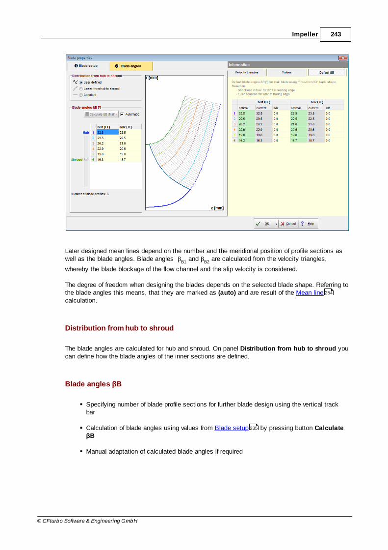
243Impeller
© CFturbo Software & Engineering GmbH
Later designed mean lines depend on the number and the meridional position of profile sections aswell as the blade angles. Blade angles
B1 and
B2 are calculated from the velocity triangles,
whereby the blade blockage of the flow channel and the slip velocity is considered.
The degree of freedom when designing the blades depends on the selected blade shape. Referring tothe blade angles this means, that they are marked as (auto) and are result of the Mean linecalculation.
Distribution from hub to shroud
The blade angles are calculated for hub and shroud. On panel Distribution from hub to shroud youcan define how the blade angles of the inner sections are defined.
Blade angles βB
Specifying number of blade profile sections for further blade design using the vertical trackbar
Calculation of blade angles using values from Blade setup by pressing button CalculateβB
Manual adaptation of calculated blade angles if required
254
235

244 CFturbo 9.2
© CFturbo Software & Engineering GmbH
Calculation or input of blade angles can be executed for 2 up to 11 blade profiles. Further bladedesign is realized according to the defined blade profile number. All meridional lines which will beused for blade design are displayed in the diagram. The number of lines can be adjusted with thetrack bar on the left side of the table. By default the meridional lines are equally spaced between huband shroud.
When using 2D blade shapes a low number of profiles may be sufficient in dependence of theleading edge shape, e.g. for a straight leading edge. For that reason the initial design for ventilatorsis made by 2 blade profiles.
Blade angles are computed under consideration of the equations listed below. They remainunchanged by default if they are determined once. If main dimensions or meridional contours aremodified or, on the other hand, values of blade thickness or slip velocity are renewed, a recalculationof blade angles should be executed by pressing the button Calculate B. This recalculation ismade automatically if the checkbox Automatic is selected.
Details of calculation of Inlet triangle
Details of calculation of Outlet triangle
(auto)
For special blade shapes some restrictions are existing and only the blade angles of the mastermean line at hub can be calculated or adapted manually. The angles of all other sections arecalculated automatically later during the mean line design because they depend on the mean lineshape. This fact is indicated by the caption "(auto)" in the table. This means that there is a couplingcondition based on the selected blade shape that results in an automatic calculation of the bladeangles. The blade angles can be displayed in the mean line dialog in the “Informational values”panel.
Radial element blades
For Radial element blades the number of blade profiles is fixed to 11. Beyond it a Distributionexponent is discernable. This exponent has influence on the distribution of the blade profiles andherewith especially on the shape of the leading edge (turbine). For highly spatial curved blades thecontinuity of the blade surface can be influenced by this parameter.
Distribution exponent Impact
Value 1: blade profiles uniformly distributed (default)
Value<1: blade profiles concentrated towards shroud
Value>1: blade profiles concentrated towards hub
Circular blades
245
248
254
261

245Impeller
© CFturbo Software & Engineering GmbH
For circular blades the radius of the blade R is displayed below the blade angle table for information.This radius depends on the radii r
1, r
2 and blade angles
B1,
B2 at leading and trailing edge. If the
calculation of the circular blade is not possible a warning symbol is displayed.
Possible warnings
Problem Possible solutions
Blade angles are updated automatically.Therefore geometry modifications are possible.
Blade angles are updated automatically if anyinput parameters are modified.
To fix the blade angles you could uncheck the"Automatic" calculation. Then you have tomanually start the calculation if required.
Blade angles are not updated automatically.Therefore the design could be not up-to-date.
Blade angles are not updated automatically ifany input parameters are modified.
To be sure that all parameter modifications areconsidered you could switch to an automaticcalculation by checking the "Automatic" option.
8.3.2.1 Inlet triangle
The inlet triangle is defined by inflow parameters and geometrical dimensions on leading edge.
Between inlet area and leading edge the swirl is constant because transmission of energy fromrotating impeller to fluid occurs in blade area only. Cross sections 0 and 1 (see Main dimensions )are different only due to blockage of the flow channel by blades (
1) in section 1. This results in an
increased meridional velocity cm
.
166

246 CFturbo 9.2
© CFturbo Software & Engineering GmbH
1u
1m1
w
ctan
10m1m cc
B1
11
11
11
11
sin
s,
z
dtwith
t
t
110m bdQc
1u11u cuw
ndu 11
1
SrS
1
SuS1u
r
r1u
r
rcc
(const. inflow swirl)
Selected blade angle β1B
does only indirectly influence the velocity triangle due to blade blockage.
Differences between selected blade angle β1B
and flow angle β1 is referred as the incidence angle: i
= β1B
-β1
In general an inflow without any incidence is intended (i=0). If i 0 the flow around the leading edgeshows high local velocities and low static pressure:
i > 0: β1 < β
1B stagnation point on pressure side
i < 0: β1 > β
1B stagnation point on suction side
A small incidence angle i can be profitable for best efficiency point. Calculation of β1B
inside CFturbo
gives inflow without incidence.
Typical inlet blade angles are:
Pumps, Ventilators β1B
< 40° due to best efficiency
Pumps β1B
as small as possible due to cavitation; with regard to efficiency not
smaller then 15…18°
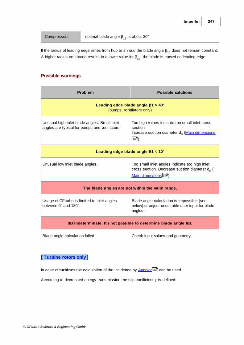
247Impeller
© CFturbo Software & Engineering GmbH
Compressors optimal blade angle β1B
is about 30°
If the radius of leading edge varies from hub to shroud the blade angle β1B
does not remain constant.
A higher radius on shroud results in a lower value for β1B
- the blade is curved on leading edge.
Possible warnings
Problem Possible solutions
Leading edge blade angle β1 > 40°(pumps, ventilators only)
Unusual high inlet blade angles. Small inletangles are typical for pumps and ventilators.
Too high values indicate too small inlet crosssection.Increase suction diameter d
S (Main dimensions
)
Leading edge blade angle ß1 < 10°
Unusual low inlet blade angles. Too small inlet angles indicate too high inletcross section. Decrease suction diameter d
S (
Main dimensions )
The blade angles are not within the valid range.
Usage of CFturbo is limited to inlet anglesbetween 0° and 180°.
Blade angle calculation is impossible (seebelow) or adjust unsuitable user input for bladeangles.
ßB indeterminate. It's not possible to determine blade angle ßB.
Blade angle calculation failed. Check input values and geometry.
[ Turbine rotors only ]
In case of turbines the calculation of the incidence by Aungier can be used.
According to decreased energy transmission the slip coefficient is defined:
166
166
250

248 CFturbo 9.2
© CFturbo Software & Engineering GmbH
2
1u1u
u
cc1
8.3.2.2 Outlet triangle
The outlet triangle is determined by geometrical dimensions of flow channel and selected bladeangle β
2B. The blade angle β
2B strongly affects the transmission of energy in the impeller therefore it
has to be chosen very carefully.
Similar to the inlet the velocity triangles in cross sections 2and 3 are different due to blockage of the flow channel byblades
2 in section 2.
2u
2m2
w
ctan
23m2m cc
B2
22
22
22
22
sin
s,
z
dtwith
t
t
223m bdQc
2u22u cuw
ndu 22
2
r2
1h2u
u
1uYc
0u13u2h
cucuY
Y~:from
249Impeller
© CFturbo Software & Engineering GmbH
For determination of β2B
it is important to be aware about the deviation between flow angle and blade
angle. The direction of the relative flow w2 at impeller outlet does not follow exactly with the blade
contour at angle β2B
. The flow angle β2 is always smaller than blade angle β
2B due to the slip
velocity. This difference is called deviation angle δ:
2B2
The deviation angle should not exceed 10°…14°, in order to limit increased turbulence losses byasymmetric flow distribution.
A reduced flow angle β2 results in smaller circumferential component of absolute speed c
u2, which is
- according to Euler's equation - dominant for the transmission of energy. Blade angle β2B
is
estimated by cu2,8
for blade congruent flow (see figure). Therefore an estimation of slip is necessary.
Slip can be estimated by empirical models. Three different possibilities are available in CFturbo (notfor Turbines):
(1) Decreased output by PFLEIDERER
(2) Outflow coefficient by WIESNER
(3) Outflow coefficient by AUNGIER
Blade angle β2B
must be determined to reach the desired energy transmission - respectively the
required head/ pressure difference - under consideration of slip velocity.
The following recommendations for common blade angles β2B
exist due to optimal efficiency:
Pumps 15°...45°, commonly used 20°...27°
Ventilators not higher than 50°
Compressors 35°...50°, unshrouded impellers up to 70°...90°
Turbines radius dependent, see sine rule
Radial machines - except for turbines - with low specific speed nq usually have similar values for β2B
. The blades for this type of impellers are often designed with a straight trailing edge (β2B
=const.).
For turbine rotors the radii along the trailing edge from hub to shroud are very different, resulting invery different values for β
2B and twisted blades.
Possible warnings
251
253
250
264

250 CFturbo 9.2
© CFturbo Software & Engineering GmbH
Problem Possible solutions
Trailing edge blade angle ß2 < 10°
Unusual low outlet blade angles Too small outlet angles indicate too high outletcross section.Decrease impeller diameter d
2 or outlet width b
2
(Main dimensions )
The deviation (slip) between blade and flow δ > 20°(pumps, ventilators, compressors only)
Unusual high deviation (slip) between blade andflow direction at outlet. This indicates too highblade loading.
Possible solutions could be: increase theimpeller diameter (Main dimensions ),increase the number of blades, increasemeridional blade length (Meridional contour ),select a different slip model
Trailing edge blade angle ßB2 > 90°.
Unusual high blade angles at trailing edge. Theblades are forward curved.
Increase impeller diameter d2 or outlet width b
2
(Main dimensions ) and/or the slip coefficientγ.
The blade angles are not within the valid range.
Usage of CFturbo is limited to blade anglesbetween 0° and 180°.
Blade angle calculation is impossible (seebelow) or adjust unsuitable user input for bladeangles.
ßB indeterminate. It's not possible to determine blade angle ßB.
Blade angle calculation failed. Try to increase the impeller diameter d2 or outlet
width b2 and/or the slip coefficient γ.
8.3.2.2.1 Slip coeff icient by AUNGIER
Outflow (slip) coefficient is defined for the decreased energy transmission:
2
2u2u
u
cc1
166
166
210
166

251Impeller
© CFturbo Software & Engineering GmbH
The cu-difference is called slip velocity.
The smaller the outflow coefficient, the higher the deviation of flow compared to the direction given byblade.
Aungier adjusted Wiesner's original empirical equation for the estimation of outflow coefficient:
7.0
2sin1
zB
The limiting radius ratio εLim
is given by:
B
BLim
2
2
2.019sin1
2.019sin
The slip factor is corrected for radius ratios ε = r/r2 > ε
Lim with:
10/2
11
B
Lim
Limcor
[ Compressors only ]
The model is further adjusted in case it is applied to splitter blades. Then the number of blades in theabove equation is corrected by the relative splitter blade length with respect to the main blade length.
mB
sBsBmBcor
L
lzzz
Circumferential component of blade congruent flow can be calculated as follows:
22u2u u1cc
8.3.2.2.2 Slip coeff icient by PFLEIDERER
Reduced energy transmission is expressed by decreased output coefficient p:
253

252 CFturbo 9.2
© CFturbo Software & Engineering GmbH
1Y~
Y~p
This coefficient can be empirically calculated in dependence of experience number ':
zS
r'p
22
2
1
r
r
rdxS
static moment from leading to trailing edge
601a' 2 experience number
experience number a:
Radial impeller with guided vanes a = 0.6
with volute a = 0.65…0.85
with plain diffusor a = 0.85…1.0
Mixed flow/axial impeller a = 1.0 …1.2
(the numbers are valid for sufficiently high Re; ’ strongly grows with small Re)
More descriptive is the decreased output factor kL:
u
uL
rc
rc
Y~Y~
p1
1k
(kL=1: for flow congruent to blade)
Circumferential component of the flow, which is congruent to blade, can be calculated as follows:
rL2
21
L
2u2u 1n21
k
1
r
r
k
cc

253Impeller
© CFturbo Software & Engineering GmbH
Now the outflow (slip) coefficient according to Wiesner can be calculated:
2
2u2u
u
cc1
8.3.2.2.3 Slip coeff icient by WIESNER
Outflow (slip) coefficient is defined for the decreased energy transmission:
2
2u2u
u
cc1
The cu-difference is called slip velocity.
The smaller the outflow coefficient, the higher the deviation of flow compared to the direction given byblade.
Wiesner has developed an empirical equation for the estimation of outflow coefficient:
w7.0
B21 k
z
sin1f
with correction values
impellers flow-mixed for50n102.102.1
impellers radial for98.0f
q31
3
Lim
Lim2m1
Lim2m1
w
1
dd1
ddfor1
k
2Hub,1
2Shroud,1m1 dd*5.0d
z
sin16.8exp B2
Lim
Circumferential component of blade congruent flow can be calculated as follows:
22u2u u1cc
253

254 CFturbo 9.2
© CFturbo Software & Engineering GmbH
8.3.2.2.4 Slip coeff icient by GÜLICH (w aste w ater pumps)
For waste water pumps the slip mainly depends on the number of blades.
The table contains typical values for the slip coefficient γ:
number of blades slip coefficient γ
1 0.48 ... 0.6
2 0.53 ... 0.65
3 0.67 ... 0.75
8.4 Blade mean lines
? Impeller | Blade mean lines
The blade mean lines are designed on the number of meridional flow surfaces which were determinedin Blade properties .
The spatially curved meridional flow surfaces are mapped to aplane by coordinate transformation. This coordinate systemhas the angle in circumferential direction t as abscissa andthe dimensionless meridional extension m as the ordinate.
Both quantities are created by the reference of absolutedistances in meridional (M) and tangential direction (T) to thelocal radius r:
r
dTdt
r
dMdm
dt
dmtan
This conformal mapping allows the uniform handling of various impeller types (radial, mixed-flow,axial).
It should be noted that for each meridional flow surface a separate m-coordinate is existing.
234
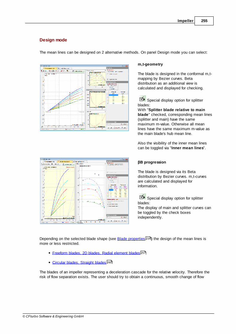
255Impeller
© CFturbo Software & Engineering GmbH
Design mode
The mean lines can be designed on 2 alternative methods. On panel Design mode you can select:
m,t-geometry
The blade is designed in the conformal m,t-mapping by Bezier curves. Betadistribution as an additional view iscalculated and displayed for checking.
Special display option for splitterblades:With "Splitter blade relative to mainblade" checked, corresponding mean lines(splitter and main) have the samemaximum m-value. Otherwise all meanlines have the same maximum m-value asthe main blade's hub mean line.
Also the visibility of the inner mean linescan be toggled via "Inner mean lines".
βB progression
The blade is designed via its Betadistribution by Bezier curves. m,t-curvesare calculated and displayed forinformation.
Special display option for splitterblades:The display of main and splitter curves canbe toggled by the check boxesindependently.
Depending on the selected blade shape (see Blade properties ) the design of the mean lines ismore or less restricted.
Freeform blades, 2D blades, Radial element blades
Circular blades, Straight blades
The blades of an impeller representing a deceleration cascade for the relative velocity. Therefore therisk of flow separation exists. The user should try to obtain a continuous, smooth change of flow
234
257
260
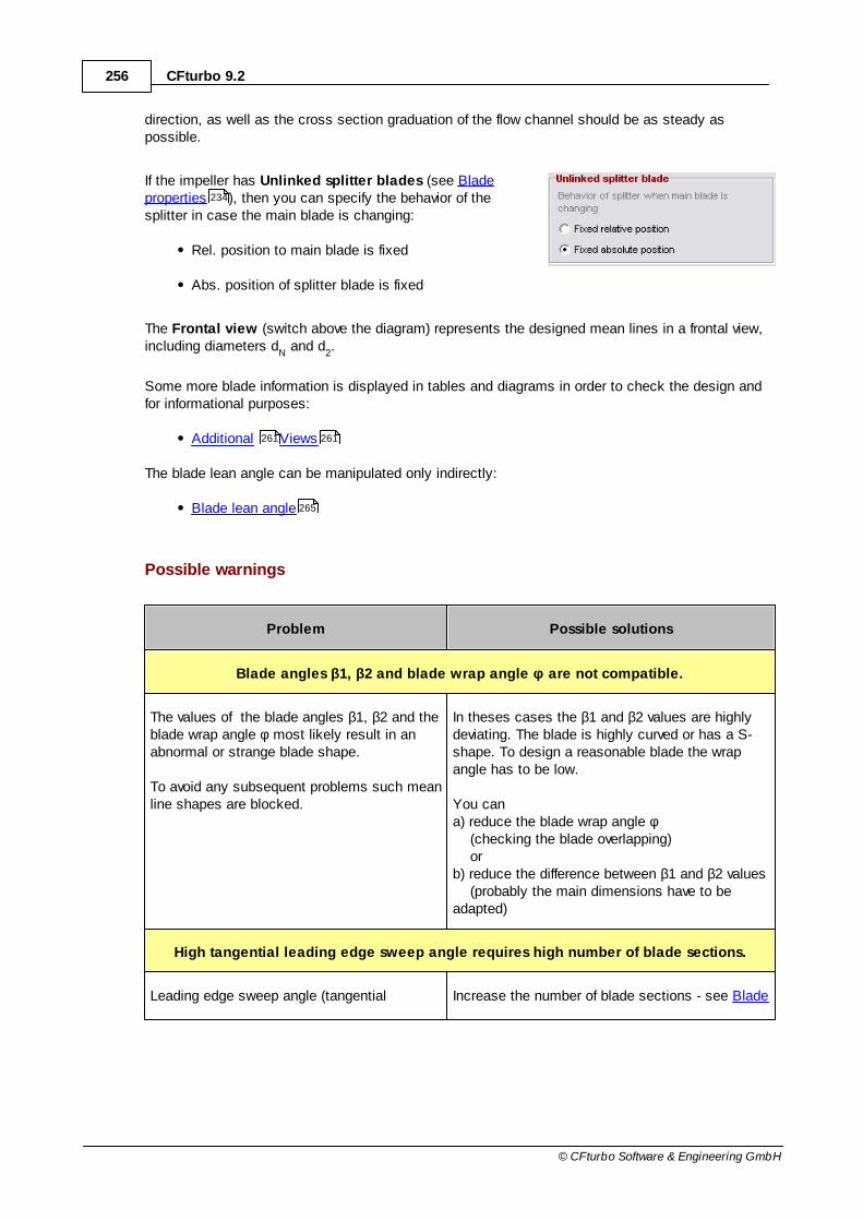
256 CFturbo 9.2
© CFturbo Software & Engineering GmbH
direction, as well as the cross section graduation of the flow channel should be as steady aspossible.
If the impeller has Unlinked splitter blades (see Bladeproperties ), then you can specify the behavior of thesplitter in case the main blade is changing:
Rel. position to main blade is fixed
Abs. position of splitter blade is fixed
The Frontal view (switch above the diagram) represents the designed mean lines in a frontal view,including diameters d
N and d
2.
Some more blade information is displayed in tables and diagrams in order to check the design andfor informational purposes:
Additional Views
The blade lean angle can be manipulated only indirectly:
Blade lean angle
Possible warnings
Problem Possible solutions
Blade angles β1, β2 and blade wrap angle φ are not compatible.
The values of the blade angles β1, β2 and theblade wrap angle φ most likely result in anabnormal or strange blade shape.
To avoid any subsequent problems such meanline shapes are blocked.
In theses cases the β1 and β2 values are highlydeviating. The blade is highly curved or has a S-shape. To design a reasonable blade the wrapangle has to be low.
You cana) reduce the blade wrap angle φ (checking the blade overlapping) orb) reduce the difference between β1 and β2 values (probably the main dimensions have to beadapted)
High tangential leading edge sweep angle requires high number of blade sections.
Leading edge sweep angle (tangential Increase the number of blade sections - see Blade
234
261 261
265

257Impeller
© CFturbo Software & Engineering GmbH
Problem Possible solutions
difference between hub and shroud meanlineat LE) is high. This curved shape requires aminimal number of blade sections to avoidabnormal or strange blade shape.
A warning level and an error level exist for thistest.
angles .
8.4.1 Freeform blades, 2D blades, Radial element blades
Freeform blades have the highest flexibility - the mean lines of all blade profile can be designeddirectly.
For 2D blades and radial element blades you can design the hub mean line only, all other meanlines are calculated automatically due to the constraints of the blade shape.
In general the mean lines are represented by 3rd order Bezier curves. Constraints are:
Meridional extension dm (see Meridional contour )
Start angle 0
Wrap angle
Start angle 0 defines the starting point of the mean lines. The absolute value is irrelevant, only the
position of the mean lines to each other can be influenced. If all mean lines have the same startingpoint then the leading edge starts on the same angular position on all mean lines (radial leadingedge). On panel Leading edge points you can select, if the position of points 0 of the mean linesis Constant, Linear or User defined.
Wrap angle can be specified numerically for inner (hub) and outer (shroud) mean line, in betweenthe values are interpolated.
For continuous transition between the separate mean lines (blade surface), the matching points ofeach mean line have to be Coupled linear. If you deactivate this option then you can modify allmean lines independently, inclusive individual wrap angles .
242
210

258 CFturbo 9.2
© CFturbo Software & Engineering GmbH
CFturbo's primary design is fixing point 0 (leading edge) for all cross sections at tangentialcoordinate t=0 and meridional coordinate m=0, while point 3 is determined by the meridiancoordinate of the trailing edge (dm) and the wrap angle . The initial wrap angle is based onempirical functions .
In case of Splitter blades the design options depends on the link between main and splitter bladesin the Blade properties . If Splitter blade linked to Main blade is activated there, the splitterblade is a shortened main blade. The blade- and wrap-angles are calculated automatically. Under Constraints the relative position of the splitter blade between two main blades can be adjusted. Itcouldn't be set on all profiles user defined like the Start angle
0.
If main and splitter blades are not linked there are all degrees of freedom in design for both.
The m-t-view of the splitter blades is shown on a separate tab (Splitter blade (m-t)). Additionally theprofiles of the contiguous blades are shown. By default they are positioned relatively by their m-coordinate. That can be changed under Display options by selecting another Splitter to mainposition (m-t).
In case of Turbines the situation is vice versa: The leading edge is located at high meridionalcoordinates whereas the trailing edge is at zero.
The wrap angle is initially constant for all cross sections, but it can be modified individually. The
124
242

259Impeller
© CFturbo Software & Engineering GmbH
wrap angle tremendously influences the blade angle progression (βB) along the mean line. Beta-
progression can be viewed in a separate diagram.
Two points in the middle, 1 and 2, must be on a straight line at an angle of βB1
or βB2
to the
horizontal in order to fulfill the boundary condition: β = dm/dt
The primary design shows points 2 at 1/4 of the wrap angle, and points 1 at 3/4.
Individual mean lines can be designed separately. If the linear coupling mode is active you can moveand rotate the connecting line. The positions of Bezier points of all mean lines are modifiedcorrespondingly, to get uniform profiles. If you select a point of the inner cross sections you canmove the entire connecting line. On the other hand, if you select any point of the inner or outer crosssections, you can move this point along the related straight line. This line is given by β
B1 or β
B2
(rotation of the connecting line). Points 0 (leading edge) and 3 (trailing edge) can only be movedhorizontally (m=const). Points 3 can be moved interactively (move/ rotate trailing edge). Points 0(leading edge) can moved only by modifying wrap angles in table Boundary conditions.
By activating the Central Bezier point option a flexible central point is added for representing eachmean line by a 4th order Bezier curve. As a result more flexibility is provided.
In panel Blade angles the blade angles βB1
, βB2
(see Blade properties ) and the angles in x,y-
plane (frontal view) βB1,xy
, βB2,xy
are stated for information.
In panel Blade information the angles of overlap of neighboring blades B and the incidence angle i
(see Blade properties ) are stated.
Possible warnings
Problem Possible solutions
Coupling partially deactivated. Blade surface could be deformed.
The mean lines are currently not linearlycoupled, which can result in deformed bladesurfaces.
Either linear coupling has been deactivated orit is impossible because of highly deviatingblade angle values.
Activate linear coupling if it is deactivated.
Homogenize βB2
blade angle values (see Blade
properties ).
234
234
234
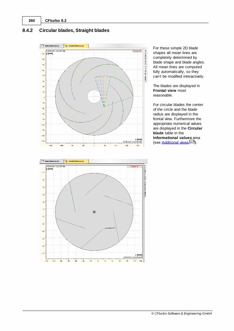
260 CFturbo 9.2
© CFturbo Software & Engineering GmbH
8.4.2 Circular blades, Straight blades
For these simple 2D bladeshapes all mean lines arecompletely determined byblade shape and blade angles.All mean lines are computedfully automatically, so theycan’t be modified interactively.
The blades are displayed in Frontal view mostreasonable.
For circular blades the centerof the circle and the bladeradius are displayed in thefrontal view. Furthermore theappropriate numerical valuesare displayed in the Circularblade table in theInformational values area(see Additional views ).261

261Impeller
© CFturbo Software & Engineering GmbH
8.4.3 Additional views
The following informationcan be displayed in themean line dialog using the"Additional views" button:
The display of the curves can be toggled by the check boxes that are accessible via in the lowercorner on the left. In case of splitter those curves of main and splitter blades can be hidden/shown.In case separate curves for suction and pressure side are existing their visibility can be toggled too.
3D-Preview
3D model of the currently designed mean surface.
Beta progression
βB progression along every mean line.
Too high local extreme values should be avoided if possible.
Blade passage area
Progression of the blade passage area within a channel built by two neighboring mean surfaces aswell as hub and shroud.
Lean angle
Distribution of the lean angle .
With the lean angle the quasi-orthogonal of the blade leans away from the z-direction. The quasi-orthogonal is a straight line connecting corresponding points on hub and shroud mean line. These
150

262 CFturbo 9.2
© CFturbo Software & Engineering GmbH
lines are setup in the blade properties dialog and are displayed in the meridional cut if just twomean lines were chosen. Otherwise the quasi-orthogonal is not displayed but internally determinedby connecting corresponding points on hub and shroud mean line.
see Blade lean angle
Relative velocity
See Blade loading calculation
Static pressure
See Blade loading calculation
Abs. circumferential velocity
See Blade loading calculation
Swirl
See Blade loading calculation
Blade loading
See Blade loading calculation
Informational values
The tables contain additional values for information:
Radial diffuser [ Stator type "Radial diffuser" only ]
Various values to verify the quality of the diffuser design.
see Mean line design for "Radial diffuser" stator type
Cross section
Throat area between neighboring mean surfaces.
242
265
267
267
267
267
267
306

263Impeller
© CFturbo Software & Engineering GmbH
This value depends on the number of blades, the wrap angle and the blade shape.
Circular blade
Radius, sector angle, center point, leading edge point, trailing edge point of circular arc.
Lean angle
Lean angle values at leading (1) and trailing edge (
2).
see Blade lean angle
Blade loading [ Pump impeller only ]
Blade loading estimation with lift coefficient (Guelich):
9.0zsin141dLz
max,a22
22Bl
a
Blade angle
Table with the blade angles βB calculated in the Blade properties dialog or computed due to
simple blade shapes.
Blade angle in x-y
Table with the blade angles of the frontal view βB,xy
.
In case of strictly radial impellers these values are consistent with the blade angles βB.
Blade angle with sine rule [ Turbine rotors only ]
Calculated blade angle using the sine rule.
For every mean line the calculated angles as well as their differences to the actual blade anglesare given in a table.
see Sine rule
Blade length and solidity
Table with:
- length of the blade mean lines in 3D
- solidity of the blade mean lines (chord length divided by (π d2/z))
Other information
265
234
264

264 CFturbo 9.2
© CFturbo Software & Engineering GmbH
Table with:
- resulting angles of overlapping B of 2 neighboring blades
- incidence angle i for hub and shroud
8.4.3.1 Sine rule
[ Turbine rotors only ]
With the help of the sine rule blade angles at the outlet can be evaluated. In accordance to this ruleblade angles at the outlet should have almost the same size as the angle that is built by ahypotenuse being the pitch t, and a cathetus (opposite leg) being the smallest distance between twoneighboring mean lines eq at a flow surface. If this is the case the outflow can be regarded asalmost tangential to the trailing edge.
t
eqsin 2'B
This is shown in a picture for a single mean line.
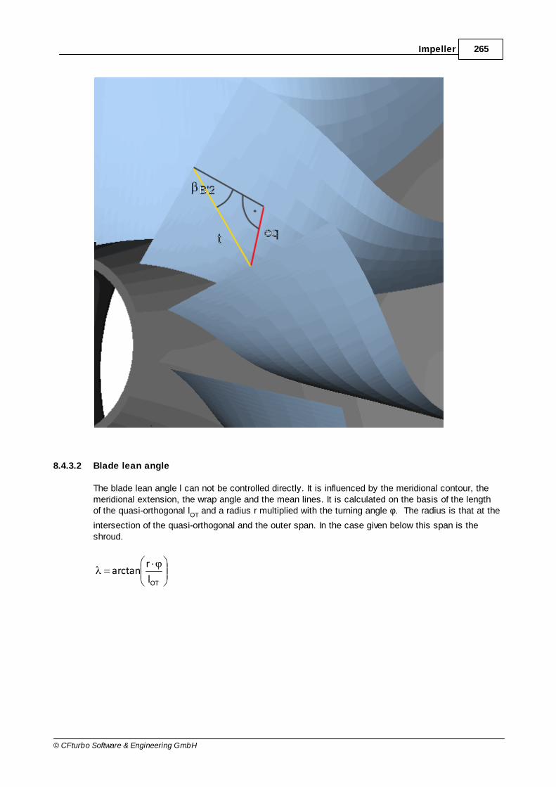
265Impeller
© CFturbo Software & Engineering GmbH
8.4.3.2 Blade lean angle
The blade lean angle l can not be controlled directly. It is influenced by the meridional contour, themeridional extension, the wrap angle and the mean lines. It is calculated on the basis of the lengthof the quasi-orthogonal l
OT and a radius r multiplied with the turning angle φ. The radius is that at the
intersection of the quasi-orthogonal and the outer span. In the case given below this span is theshroud.
OTl
rarctan

266 CFturbo 9.2
© CFturbo Software & Engineering GmbH
With an example of a compressor some means for the manipulation of the blade lean

267Impeller
© CFturbo Software & Engineering GmbH
angle are given:
1?: blade angle β
B1
1??: move second Bezier point at leading edge
1?: wrap angle
1? and enlargement of the curvature: reduction of the meridional extension of the meridional
contour
8.4.4 Blade loading calculation
Determination of velocity distribution on impeller blades by Stanitz & Prian
Stream lines must be known a-priori (¢ see Meridional flow calculation ). Stream lines rotatedaround z-axis build stream surfaces.The relative velocities will be calculate in a blade-to-bladesection, that is encapsulated by two adjacent stream surfaces. Single values of relative velocities willbe determined at r = constant. Before that an average velocity is calculated on the basis of thecontinuity equation:
A
mw
The part mass flow is a function of the entire mass flow, number of blades and number of streamlines. Between two adjacent stream surfaces there is always the same mass flow.
242
257
257
210
355
230
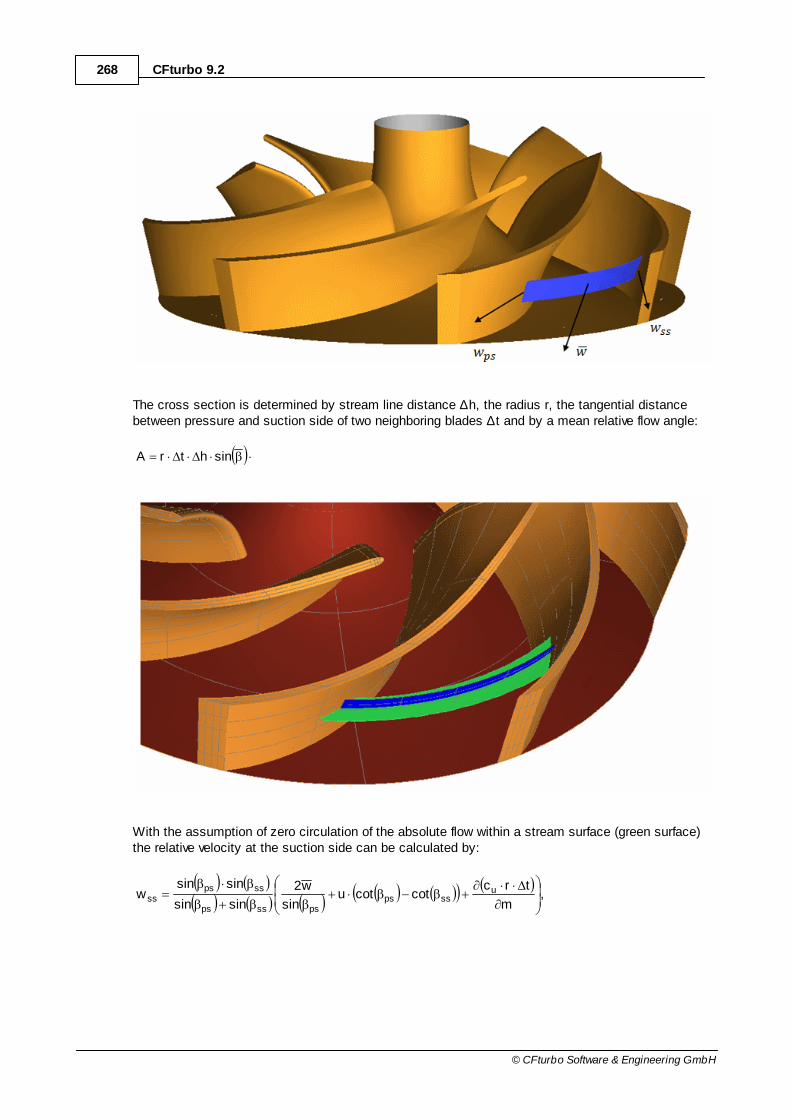
268 CFturbo 9.2
© CFturbo Software & Engineering GmbH
The cross section is determined by stream line distance ∆h, the radius r, the tangential distancebetween pressure and suction side of two neighboring blades ∆t and by a mean relative flow angle:
sinhtrA
With the assumption of zero circulation of the absolute flow within a stream surface (green surface)the relative velocity at the suction side can be calculated by:
,m
trccotcotu
sin
w2
sinsin
sinsinw u
sspspsssps
sspsss

269Impeller
© CFturbo Software & Engineering GmbH
here u is the local circumferential velocity, cu is the circumferential component of the absolute
velocity, βss
and βps
are the blade angles at suction and pressure side respectively. Due to the fact
that mean relative velocity is an averaged value of wss
and wps
, the relative velocity at the pressure
side can be calculated with:
ssps ww2w
Annotation
The continuity equation has to be solved iteratively for the relative velocity since the density of acompressible medium is determined by the relative velocity. The density can be calculated fromisentropic relation:
1
1
22
1t1t
2
u
2
w
TR
111
The average relative flow angle is approximated by the average value of the blade angle at suction-and pressure side. At a certain radius the assumption applies that due to the slip (decreased power)the flow cannot be considered as blade congruent anymore. The mean relative flow angle will becorrected by the slip at loci with a radius bigger than this Stanitz-Radius.
The whole procedure is based on the assumption that the flow is considered as frictionless and thatshocks as well as heat transport across boundaries do not occur.
Blade loading
Static pressures at suction and pressure side can be determined by the relative velocities. To thisend a relation between the enthalpy difference between suction and pressure side and the meridionalderivative of the swirl is used:
m
crc
n
2hh u
mssps
The blade loading can be expressed in terms of the pressure difference between suction andpressure side and divided by the total inlet pressure:
sspsvu
mav
totalin
ssps TTcm
crc
np
pp 2
,
For incompressible fluids the second therm within the brackets is zero.
Other quantities

270 CFturbo 9.2
© CFturbo Software & Engineering GmbH
Beyond the afore mentioned variables the average circumferential component of the absolute velocityc
u as well as the average swirl B can also be displayed. Those quantities are determined by:
,coswucu
.crB u
Also the Ackeret criteria are displayed together with the relative velocities. In accordance to thebelow defined Ackeret criteria the maximum relative velocity of the respective span shall not be
bigger than 1.8·w2, whereas the minimum relative velocity shall not be smaller than 0.3·w
1:
,1
2w
wAckeret
,8.12
maxw
wAckeret max
.3.01
minw
wAckeretmin
8.5 Blade profiles
? Impeller | Blade profiles
To create blade profiles (main and splitter) the orthogonal blade thickness distribution for the hub andthe shroud profile is used. By default the thickness is defined at leading edge, at trailing edge and atthe control points of the blade. For the initial CFturbo-design, typical values in dependence on theimpeller diameter d
2 are used (see Approximation functions ).
Waste water pumps have their own specific thickness distribution with very high thickness at leadingedge to avoid solid attachments. Starting from 20% of the blade length the thickness is constant upto the trailing edge.
The representation of the thickness distribution is made along the relative blade length (0 = leadingedge, 1 = trailing edge).
124
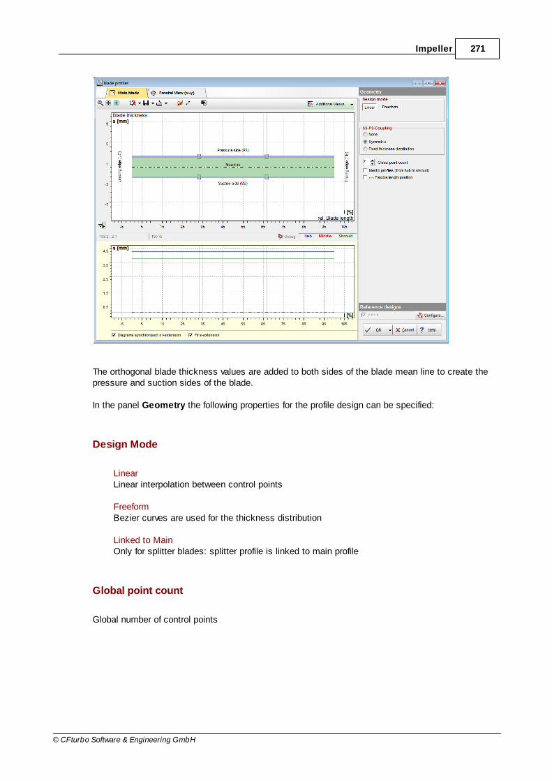
271Impeller
© CFturbo Software & Engineering GmbH
The orthogonal blade thickness values are added to both sides of the blade mean line to create thepressure and suction sides of the blade.
In the panel Geometry the following properties for the profile design can be specified:
Design Mode
LinearLinear interpolation between control points
FreeformBezier curves are used for the thickness distribution
Linked to MainOnly for splitter blades: splitter profile is linked to main profile
Global point count
Global number of control points

272 CFturbo 9.2
© CFturbo Software & Engineering GmbH
Identic profiles
All profiles have the same thickness distribution
Flexible length position
Shifting control points in horizontal direction
SS-PS-Coupling
NoneNo coupling between suction side and pressure side
SymmetricSymmetric thickness distribution: control points on suction and pressure side are coupled
Fixed thickness distributionShifting the thickness distribution to pressure/suction side whereas the distribution itselfremains constant
Each thickness curve has a popup menu to add/removepolygon/Bezier points, to load or save the curve and to resetthe distribution to default.
For Bezier curves a Polyline to Bezier conversion ispossible.
Info
The Info panel represents information of the designed blade profile.
Throat areaSmallest cross section between 2 neighboring blades
Actual thicknessActual orthogonal blade thickness values of hub and shroud profiles at leading edge, at trailingedge, after 1/3 and after 2/3 of the blade lengthIf the cells are colored red, then the thickness on leading/trailing edge is differing from theTarget thickness.
273

273Impeller
© CFturbo Software & Engineering GmbH
Target thicknessOrthogonal blade thickness values for hub and shroud profiles at leading edge and at trailingedge as defined in the Blade properties dialog.Please note that the blade thickness on leading and trailing edge should be modified in the Blade properties dialog only. In this case the blade angle calculation should be updated dueto the blade blockage.
Display options
The Display options only influence the graphical representation. For instance, the visibility of thesmallest cross section can be toggled.
The Frontal view (switch abovethe diagram) represents thedesigned profiles in a frontal view,including diameters d
N and d
2.
Furthermore, the smallest crosssection between 2 neighboringprofiles is displayed.
8.5.1 Converting Polyline / Bezier
Any existing thickness distributioncan be converted to a Bezier curvefor further modifications.
234
234
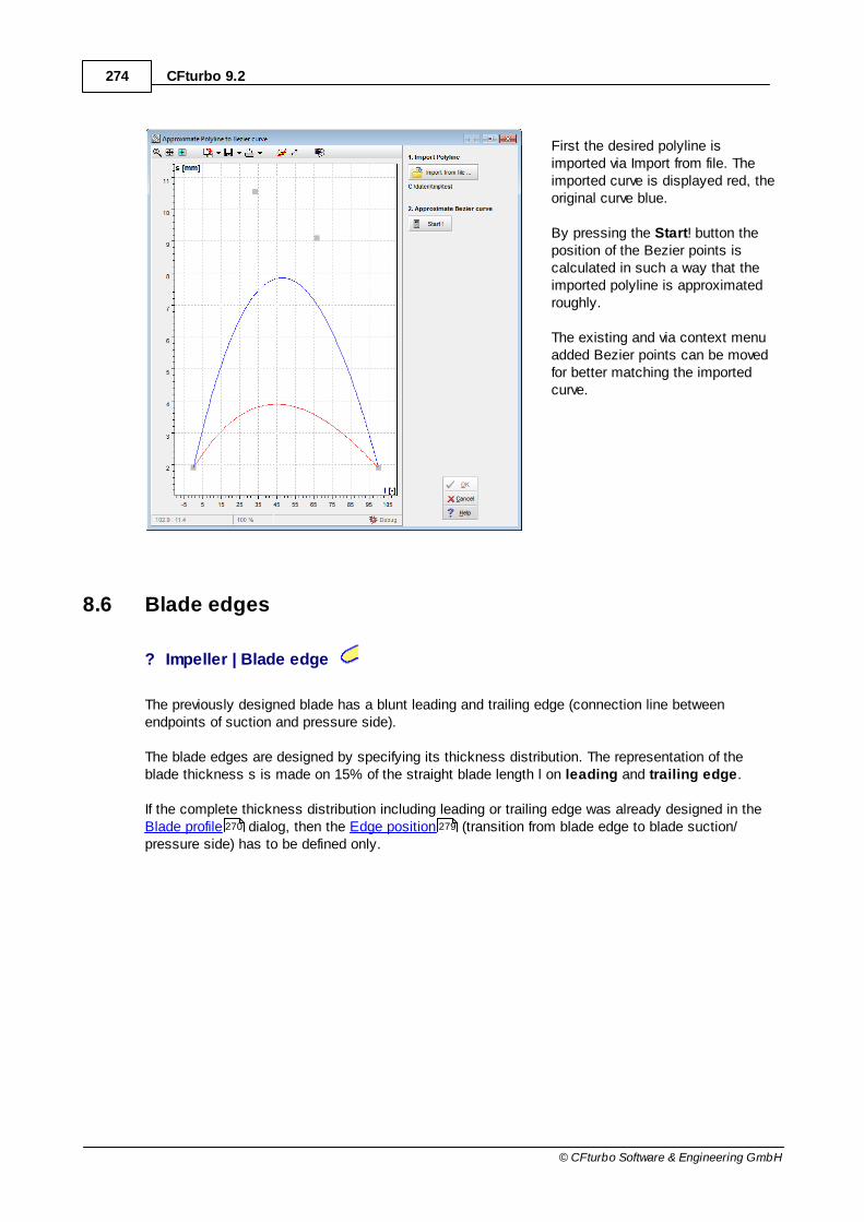
274 CFturbo 9.2
© CFturbo Software & Engineering GmbH
First the desired polyline isimported via Import from file. Theimported curve is displayed red, theoriginal curve blue.
By pressing the Start! button theposition of the Bezier points iscalculated in such a way that theimported polyline is approximatedroughly.
The existing and via context menuadded Bezier points can be movedfor better matching the importedcurve.
8.6 Blade edges
? Impeller | Blade edge
The previously designed blade has a blunt leading and trailing edge (connection line betweenendpoints of suction and pressure side).
The blade edges are designed by specifying its thickness distribution. The representation of theblade thickness s is made on 15% of the straight blade length l on leading and trailing edge.
If the complete thickness distribution including leading or trailing edge was already designed in the Blade profile dialog, then the Edge position (transition from blade edge to blade suction/pressure side) has to be defined only.
270 279
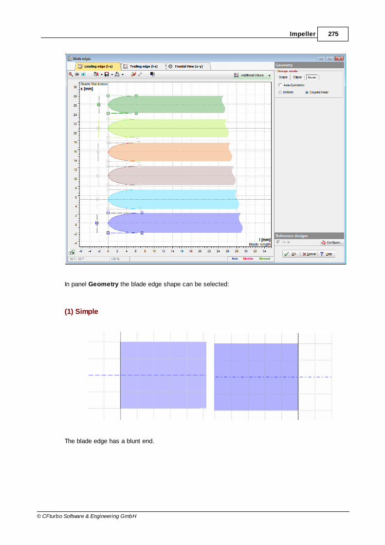
275Impeller
© CFturbo Software & Engineering GmbH
In panel Geometry the blade edge shape can be selected:
(1) Simple
The blade edge has a blunt end.

276 CFturbo 9.2
© CFturbo Software & Engineering GmbH
A straight line is calculated from the endpoint of suction side perpendicular to the mean line.
Trim on inlet/outlet effects trimming the blade on the corresponding inlet or outlet surface. Thetrimming is possible on the trailing edge only (or on the leading edge of turbines).
(2) Ellipse
The blade edge is rounded elliptically.
The semi-axis ratio can be defined. One axis runs on the mean line, the other perpendicular.
(3) Bezier
For this purpose 4th order Bezier curves are used.
Points 0 and 4 representing the transition between the blade sides and the rounded blade edge. Youcan move these points only along the corresponding blade side. Bezier points 1 and 3 can only bemoved on straight lines which correspond to the gradient of the curve in points 0 or 4, respectively inorder to guarantee smooth transition from the contour to the blade edge. Bezier point 2 is not

277Impeller
© CFturbo Software & Engineering GmbH
restricted to move - it has the most influence to the shape of the blade edge. Its horizontal positionis calculated automatically in such way that the leading edge starts at position l=0 and the trailingedge ends at position l=blade length. The blade edges are designed at the first or last 10% of theblade length.
Axis-Symmetric results in symmetric geometry, i.e. points 0/4 and 1/3 have the same horizontalposition and point 2 is on the middle line.
There are two different possibilities to determine the shape of the blade edge. In the Bezier curveoption panel you can select between:
Coupled linear:only blade edges of hub and shroud will be fixed, while anything between will be interpolatedlinearly
Uniform:when designing blade edge on hub or shroud then Bezier points of all other leading edgeshave the same relative positions
Info
Info area represents information of Blade edge design.
Display options
Display options only influence the graphical representation. For instance, the visibility of the smallestcross section can be toggled.
The Frontal view (switch above thediagram) represents the designed blades in afrontal view, including diameters d
N und d
2.
Furthermore the smallest cross sectionbetween 2 neighboring blades is displayed.

278 CFturbo 9.2
© CFturbo Software & Engineering GmbH
Possible warnings
Problem Possible solutions
The blade exceeds the meridional boundaries.
The orthogonal application of thickness on themean lines can result in some blade positionoutside the meridional boundaries. As a resultthe model finishing option 'solid trimming'will probably fail.
Dependent upon the location of these areas onehas to modify leading or trailing edge. If theleading edge (or the trailing edge of turbines)exceeds the meridional boundaries you canadjust it in the Meridional contour dialog only.Exceeding trailing edge (or leading edge ofturbines) can be corrected by trim on in/outlet.
Error Trim Hub/Shroud on Blade: Check blade angles and thickness.
Trim may be poor/failed, due to meridional contour at suction port and LE.
The orthogonal blade thickness is added to theblade mean line to create the blade.
After this the blades will be automaticallytrimmed with hub and shroud.
Note: blade surfaces cannot be trimmedreasonably on hub and shroud for someconfigurations of meridional contour and bladegeometries.
Meridional contour : Account for bladethickness during leading edge positioning or alignleading edge towards the direction of the shroudnormal (see images below).
The trimming between blade and hub / shroud willbe done successfully depending on blade anglesand blade thickness. A solution can be themodification of the leading edge by repositioningand changing its angle relative to the shroud.
Blade profile : Change blade thickness
Mean line : Check m-t and lean angle direction
290
210
210
270
254

279Impeller
© CFturbo Software & Engineering GmbH
Problem Possible solutions
8.6.1 Edge position
If the complete thickness distribution including leading or trailing edge was already designed in the Blade profile dialog, then the Edge position (transition from blade edge to blade suction/pressure side) has to be defined only.
270 279

280 CFturbo 9.2
© CFturbo Software & Engineering GmbH
In panel Geometry the transition from the blade edge to the suction/pressure side can be defined.
Position in % of the straight blade length.
The leading edge should be within the range of 0% to15%, the trailing edge between 85% and 100%.
8.7 CFD Setup
? Impeller | CFD setup
The designed geometry can be extended by virtual elements.
Extension
Impeller segment
Blade O-Grid
Through - flow area
281
284
287
287
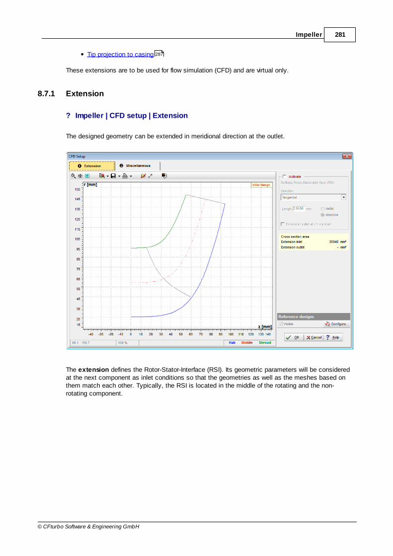
281Impeller
© CFturbo Software & Engineering GmbH
Tip projection to casing
These extensions are to be used for flow simulation (CFD) and are virtual only.
8.7.1 Extension
? Impeller | CFD setup | Extension
The designed geometry can be extended in meridional direction at the outlet.
The extension defines the Rotor-Stator-Interface (RSI). Its geometric parameters will be consideredat the next component as inlet conditions so that the geometries as well as the meshes based onthem match each other. Typically, the RSI is located in the middle of the rotating and the non-rotating component.
287

282 CFturbo 9.2
© CFturbo Software & Engineering GmbH
(RSI Connection: see Other )
Using the extension is recommended, because otherwise the trailing edges of the blades would justlie on the rotor-stator interface, which can cause both meshing problems and numerical simulationerrors. Meshing problems could occur, especially for small values of the blade angle ß
2.
The drop down menu Direction sets the direction of the extension. If it is set to tangential, hub andshroud will be tangentially extended.Below you can specify the Length of the extension and whether the length should be measuredradial or absolute (i.e. in the direction specified above).Furthermore, you can set Extension outlet at r = constant, which means that the outlet of theextension is forced to be horizontal in the diagram (parallel to the z-axis).
The designed outlet extension will be displayed in the diagram automatically.
For unvaned stators, the extension is not necessary and therefore not activatable.
Possible warnings
Problem Lösungsmöglichkeiten
The length of the extension is smaller or equal to the distance tolerance. This mightcause sewing defects in "Meridian.Flow Domain" during model finishing.
The length of the extension is smaller or equalto the distance tolerance . This mightcause geometrical defects when sewing facesduring Model finishing .
If geometrical problems occur, change thedistance tolerance or the length of theextension.
Extension outlet has nearly constant radius. Selecting "Extension outlet at r = constant" isrecommended.
The endpoints of the hub and shroudextension have a slightly different radius. Thiscan result in almost flat cone surfaces for theadjacent RSI Connection, which may be
Set the endpoints of the hub and shroudextension to the same radius by checking the"Extension outlet at r = constant" checkbox.
287
288
290

283Impeller
© CFturbo Software & Engineering GmbH
Problem Lösungsmöglichkeiten
problematic to import into other CAD/CFDsystems.
8.7.2 Miscellaneous
? Impeller | CFD Setup | Miscellaneous
Miscellaneous virtual elements can be created:
Segment
Blade O-Grid
Other
284
287
287

284 CFturbo 9.2
© CFturbo Software & Engineering GmbH
8.7.2.1 Segment
? Impeller | CFD Setup | Miscellaneous | Segment
The segment is the flow passage around a single blade and represents the smallest rotation-symmetric part of the impeller.
There are the following options for the design:
"Around single blade, by rotated mean line"
The blade mean surface is rotated to both sides to the middle of the flow channel.
"Around single blade, middle of PS-SS"
The middle of blade pressure and suction side of two neighboring main blades forms the segmentboundary. This type should be used for thick asymmetric blades. It ensures that the blades do notcut the periodic surfaces of the segment.
"Between neighboring blades (ML to ML)"
The mean surfaces of two neighboring main blades form the segment boundary. This type is

285Impeller
© CFturbo Software & Engineering GmbH
currently not supported by Model finishing .
"Around single blade, by rotated mean line"
With "Smooth inlet" a smooth transition from the impeller inlet to the blade area can be designed.This surface is created by a virtual extension of the Blade mean line from the blade leading edge(which is the trailing edge in case of turbines) to the Inlet (Outlet for turbines).
There are three types of β distribution from the leading edge of the blade (βB1) to the Inlet (β inlet
):
linear
quadratic
root
The values of βB1
have been defined in the Blade properties . At the Inlet the distribution of the
angle β inlet is linear from hub to shroud.
without "Smooth inlet" with "Smooth inlet"
290
254
287
287
242 287
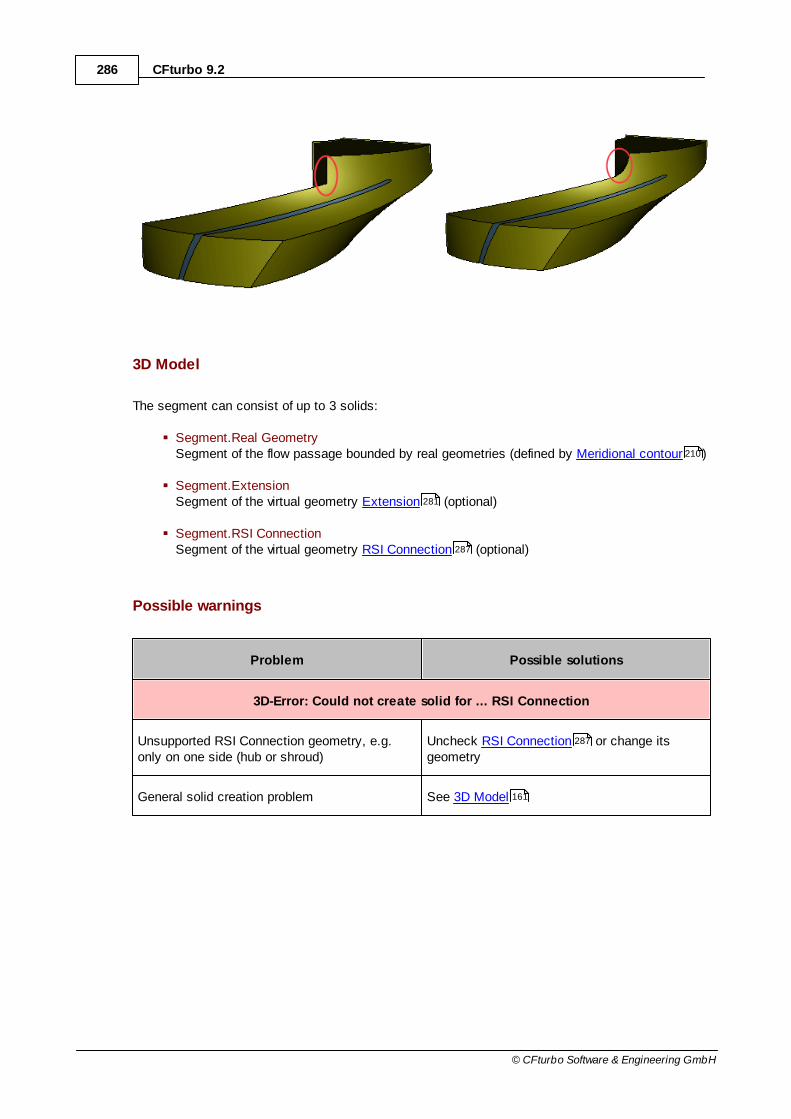
286 CFturbo 9.2
© CFturbo Software & Engineering GmbH
3D Model
The segment can consist of up to 3 solids:
Segment.Real GeometrySegment of the flow passage bounded by real geometries (defined by Meridional contour )
Segment.ExtensionSegment of the virtual geometry Extension (optional)
Segment.RSI ConnectionSegment of the virtual geometry RSI Connection (optional)
Possible warnings
Problem Possible solutions
3D-Error: Could not create solid for ... RSI Connection
Unsupported RSI Connection geometry, e.g.only on one side (hub or shroud)
Uncheck RSI Connection or change itsgeometry
General solid creation problem See 3D Model
210
281
287
287
161
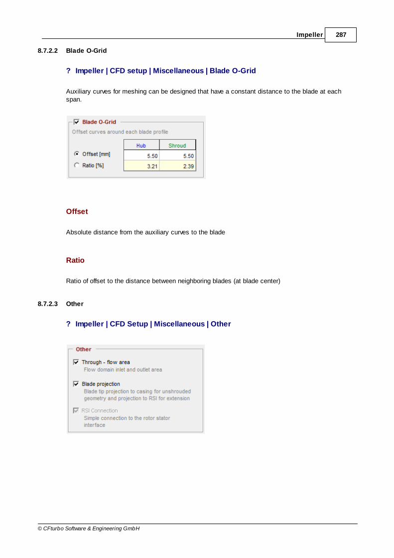
287Impeller
© CFturbo Software & Engineering GmbH
8.7.2.2 Blade O-Grid
? Impeller | CFD setup | Miscellaneous | Blade O-Grid
Auxiliary curves for meshing can be designed that have a constant distance to the blade at eachspan.
Offset
Absolute distance from the auxiliary curves to the blade
Ratio
Ratio of offset to the distance between neighboring blades (at blade center)
8.7.2.3 Other
? Impeller | CFD Setup | Miscellaneous | Other

288 CFturbo 9.2
© CFturbo Software & Engineering GmbH
Through-flow area
Inlet and outlet area define the inflow and outflow boundary of the whole flow channel.
Blade projection
In case of an unshrouded impeller the outer blade profile is projected onto the casing.
If an Extension exists, the blade trailing edge is projected onto the RSI.
This option must be enabled for a successful export to Ansys ICEM-CFD .
RSI connection
If a Rotor-Stator-Interface (RSI) is existing on the inlet side of the component, an existing gap can beclosed automatically by the RSI connection. These surfaces provide a simplified, closed volumemodel for flow simulation neglecting impeller side chambers or other casing parts.
(see also Extension )
8.8 Model settings
? Impeller | Model settings
On dialog Model settings you can specify how many data points are to be used for the 3D modeland for the point based export formats.
The number of points can be set for both cases separately for all geometry parts.
Meridian: hub/shroud
Blade: mean line, pressure/suction side, leading/trailing edge
281
112
281

289Impeller
© CFturbo Software & Engineering GmbH
3D Model
Distance tolerance (3DModel)
The distance tolerance defines the maximum allowed distancebetween sewed surfaces, e.g the faces of a solid.
If it is too small, the solids cannot be created.
If it is too big, small faces are ignored when creating a solid.
Point Export
Presetting
Select from 3 global presets.
Length unit for Export
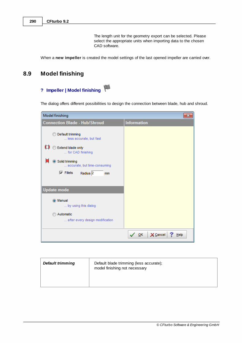
290 CFturbo 9.2
© CFturbo Software & Engineering GmbH
The length unit for the geometry export can be selected. Pleaseselect the appropriate units when importing data to the chosenCAD software.
When a new impeller is created the model settings of the last opened impeller are carried over.
8.9 Model finishing
? Impeller | Model finishing
The dialog offers different possibilities to design the connection between blade, hub and shroud.
Default trimming Default blade trimming (less accurate);model finishing not necessary
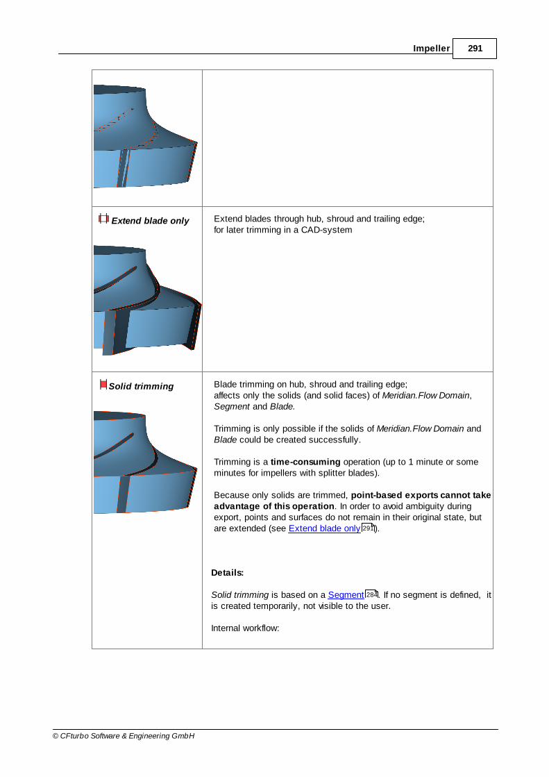
291Impeller
© CFturbo Software & Engineering GmbH
Extend blade only Extend blades through hub, shroud and trailing edge;for later trimming in a CAD-system
Solid trimming Blade trimming on hub, shroud and trailing edge;affects only the solids (and solid faces) of Meridian.Flow Domain,Segment and Blade.
Trimming is only possible if the solids of Meridian.Flow Domain andBlade could be created successfully.
Trimming is a time-consuming operation (up to 1 minute or someminutes for impellers with splitter blades).
Because only solids are trimmed, point-based exports cannot takeadvantage of this operation. In order to avoid ambiguity duringexport, points and surfaces do not remain in their original state, butare extended (see Extend blade only ).
Details:
Solid trimming is based on a Segment . If no segment is defined, itis created temporarily, not visible to the user.
Internal workflow:
291
284

292 CFturbo 9.2
© CFturbo Software & Engineering GmbH
The blades are extended (see Extend blade only )
A single blade is trimmed with Meridian.Flow Domain
From Meridian.Flow Domain, a segment is cut. In this way thetrimmed Segment.Real Geometry is created.
CFD Setup option: If there is an Extension or RSI Connection, Segment.Real Geometry is fused with Segment.Extension andSegment.RSI Connection. In this way, Segment.Flow Domain iscreated.
Segment.Flow Domain is copied multiple times. The copies arerotated and sewed in order to create a new Meridian.Flow Domain.
CFD Setup option: If Blade projection was chosen, thecorresponding projection surfaces are exactly trimmed.
Option: Blade root fillet Fillet creation at blade root;affects only the solids (and solid faces) of Meridian.Flow Domain andSegment.
The fillet radius should not be too large.
Fillet creation is notpossible if the fillets of twoneighboring blades wouldmeet or if the fillet wouldprotrude beyond theimpeller inlet.
Update mode
Manual The 3D-model is updated only after closing the dialog.
Automatic The 3D-model is updated after every design modification automatically.
Symbol in main window
The symbol shows the state of Model-finishing.
291
281 287
287
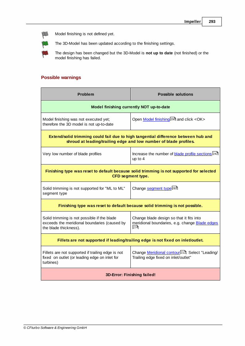
293Impeller
© CFturbo Software & Engineering GmbH
Model finishing is not defined yet.
The 3D-Model has been updated according to the finishing settings.
The design has been changed but the 3D-Model is not up to date (not finished) or themodel finishing has failed.
Possible warnings
Problem Possible solutions
Model finishing currently NOT up-to-date
Model finishing was not executed yet;therefore the 3D model is not up-to-date
Open Model finishing and click <OK>
Extend/solid trimming could fail due to high tangential difference between hub andshroud at leading/trailing edge and low number of blade profiles.
Very low number of blade profiles Increase the number of blade profile sectionsup to 4
Finishing type was reset to default because solid trimming is not supported for selectedCFD segment type.
Solid trimming is not supported for "ML to ML"segment type
Change segment type
Finishing type was reset to default because solid trimming is not possible.
Solid trimming is not possible if the bladeexceeds the meridional boundaries (caused bythe blade thickness).
Change blade design so that it fits intomeridional boundaries, e.g. change Blade edges
Fillets are not supported if leading/trailing edge is not fixed on inlet/outlet.
Fillets are not supported if trailing edge is notfixed on outlet (or leading edge on inlet forturbines)
Change Meridional contour : Select "Leading/Trailing edge fixed on inlet/outlet"
3D-Error: Finishing failed!
290
242
283
274
212

294 CFturbo 9.2
© CFturbo Software & Engineering GmbH
Problem Possible solutions
Leading edge very near to inlet Change Meridional contour : Move leadingedge towards outlet
Inlet (nearly) tangential to hub or shroud Change Meridional contour : Avoidtangentiality
210
210

Part
IX

296 CFturbo 9.2
© CFturbo Software & Engineering GmbH
9 Stator
? Stator
This chapter describes in detail the design process for stator type componentsfeatured in CFturbo.
The content reflects the design steps in the sequence they are encounteredduring the design process.
Design steps
Main dimensions
Meridional contour
Blade properties
Blade mean lines
Blade profiles
Blade edges
Model finishing
Model settings
CFD setup
9.1 Main dimensions
? Stator | Main dimensions
The Main Dimensions menu item is used to define main dimensions of the stator.
296
302
303
306
309
309
310
310
309

297Stator
© CFturbo Software & Engineering GmbH
General Shape
Here you can define the stator type initially. Currently the following types are available:
Free form
Radial diffuser
Using the button "Set default" you can set default properties for each stator type.
Blades
Here you can define if the stator should be vaned or unvaned.
For vaned stators you have to define the number of blades and the existence of splitter blades.
Via Unshrouded you can decide to design a shrouded or unshrouded stator. For unshrouded stator

298 CFturbo 9.2
© CFturbo Software & Engineering GmbH
you have to define the tip clearance.
Information
Right in the dialog some additional information are displayed.
The Meridian preview is based on the until now designed main dimensions and visualizes thegeneral proportions.
Information values lists important coefficients, which result from determined main dimensions.The specific values depend on the selected tab sheet on the left side: Extent , Inlet or Outlet
.If the font color is blue then a hint for the recommended range of this value is available when themouse cursor is on the table row.If the font color is red then the current value is outside the recommended range.
Details
Number of blades
Extent
Inlet
Outlet
299 301
302
304
299
301
302
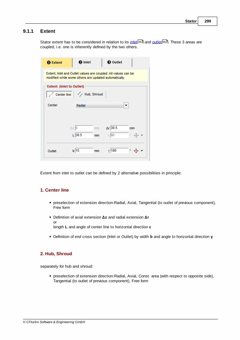
299Stator
© CFturbo Software & Engineering GmbH
9.1.1 Extent
Stator extent has to be considered in relation to its inlet and outlet . These 3 areas arecoupled, i.e. one is inherently defined by the two others.
Extent from inlet to outlet can be defined by 2 alternative possibilities in principle:
1. Center line
preselection of extension direction:Radial, Axial, Tangential (to outlet of previous component),Free form
Definition of axial extension ∆z and radial extension ∆rorlength L and angle of center line to horizontal direction ε
Definition of end cross section (Inlet or Outlet) by width b and angle to horizontal direction γ
2. Hub, Shroud
separately for hub and shroud:
preselection of extension direction:Radial, Axial, Const. area (with respect to opposite side),Tangential (to outlet of previous component), Free form
301 302

300 CFturbo 9.2
© CFturbo Software & Engineering GmbH
Definition of axial extension ∆z and radial extension ∆rorlength L and angle of hub/shroud to horizontal direction ε
The angles ε and γ are defined by 0° horizontal right and rising in counter clockwise direction(mathematical positive). A menu with some default angles is supporting angle input:
0°
180°
90°
270°
Perpendicular: ε perpendicular to inlet or outlet cross section
Parallel: γ parallel to inlet or outlet cross section
Depending on the interface type the extents are defining the inlet or the outlet of the component.35
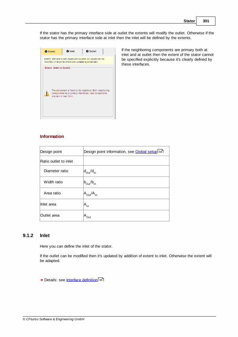
301Stator
© CFturbo Software & Engineering GmbH
If the stator has the primary interface side at outlet the extents will modify the outlet. Otherwise if thestator has the primary interface side at inlet then the inlet will be defined by the extents.
If the neighboring components are primary both atinlet and at outlet then the extent of the stator cannotbe specified explicitly because it's clearly defined bythese interfaces.
Information
Design point Design point information, see Global setup
Ratio outlet to inlet
Diameter ratio dOut
/dIn
Width ratio bOut
/bIn
Area ratio AOut
/AIn
Inlet area AIn
Outlet area AOut
9.1.2 Inlet
Here you can define the inlet of the stator.
If the outlet can be modified then it's updated by addition of extent to inlet. Otherwise the extent willbe adapted.
Details: see Interface definition
58
35

302 CFturbo 9.2
© CFturbo Software & Engineering GmbH
9.1.3 Outlet
Here you can define the outlet of the stator.
If the inlet can be modified then it's updated by subtraction of extent from outlet. Otherwise theextent will be adapted.
Details: see Interface definition
9.2 Meridional contour
? Stator | Meridional contour
In principle, the same features are available as for the meridional design of impellers.
The endpoints of hub and shroud curves are fixed by main dimensions and cannot be modifiedhere.
For "Radial diffuser" type of stators (see main dimensions ) the following geometrical dimensionsare defined:
35
210
296
296

303Stator
© CFturbo Software & Engineering GmbH
9.3 Blade properties
? Stator | Blade properties
In principle, the same features are available as for the blade properties of impellers.
To support the selection of a suitable blade count a separate dialog can be used, which can bestarted by pressing the button right beside the edit field.
The outlet angles αTE are input values for most of the blade types according to the desired changeof flow direction. Slip models are not available for stators. Some angle oversizing should beconsidered if necessary.
Two additional special blade shapes are available for "Radial diffuser" type stators (see Maindimensions ):
1. Log. Spiral + Straight 2D
The inlet section of the vanes without overlapping is noneffective and configured as a logarithmicspiral (similar to spiral casing).
The diffuser part in the overlapping area is straight. The transition point between these areas canbe moved along the logarithmic spiral curve (see mean line ).
2. Circular + Free-form 2D
The inlet section of the vanes without overlapping is configured as a circular arc with the boundaryconditions inlet radius r3, inlet angle α3 and ideal throat width a3.
The diffuser part in the overlapping area is designed by a Bezier curve with optionally 2 (straight),3 or 4 Bezier points (selectable by context menu). The transition point between these areas canbe moved along the circular arc curve (see mean line ).
Calculation of throat width a3 can be done using the conservation of angular momentum (const.swirl) or a specific deceleration ratio alternatively:
a) Const. swirl
Throat width corrsponds to the dimensioning in accordance with the conservation of angularmomentum, whereat the deceleration is increased by using the factor f
a3 (1.1...1.3).
1zrcb
Qexp
2
dfa
22u3
33a3
234
304
296
306
306

304 CFturbo 9.2
© CFturbo Software & Engineering GmbH
b) Deceleration
Alternatively one can use the deceleration ratio c3q
/c2 (0.7...0.85) for throat width calculation.
q3
2
233
c
c
czb
Qa
Trailing edge angle αTE is a result of mean line design for these special blade shapes and thereforecannot be specified explicitly ("var.").
9.3.1 Number of blades
Number of blades, stator outlet diameter and minimum blade distance are significant for the actualdiffuser part of the stator and therefore have high influence on the flow losses. These 3 parametershave to be adjusted carefully.
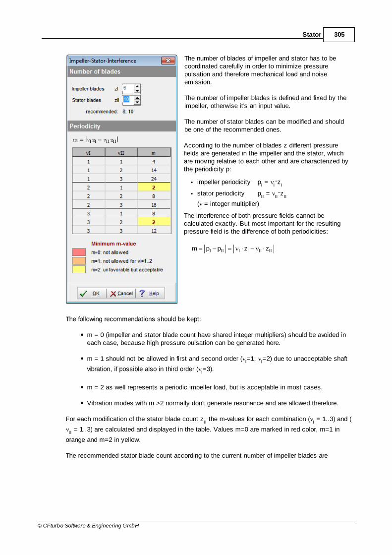
305Stator
© CFturbo Software & Engineering GmbH
The number of blades of impeller and stator has to becoordinated carefully in order to minimize pressurepulsation and therefore mechanical load and noiseemission.
The number of impeller blades is defined and fixed by theimpeller, otherwise it's an input value.
The number of stator blades can be modified and shouldbe one of the recommended ones.
According to the number of blades z different pressurefields are generated in the impeller and the stator, whichare moving relative to each other and are characterized bythe periodicity p:
impeller periodicity pI =
Iz
I
stator periodicity pII =
IIz
II
( = integer multiplier)
The interference of both pressure fields cannot becalculated exactly. But most important for the resultingpressure field is the difference of both periodicities:
IIIIIIIII zzppm
The following recommendations should be kept:
m = 0 (impeller and stator blade count have shared integer multipliers) should be avoided ineach case, because high pressure pulsation can be generated here.
m = 1 should not be allowed in first and second order (I=1;
I=2) due to unacceptable shaft
vibration, if possible also in third order (I=3).
m = 2 as well represents a periodic impeller load, but is acceptable in most cases.
Vibration modes with m >2 normally don't generate resonance and are allowed therefore.
For each modification of the stator blade count zII the m-values for each combination (
I = 1..3) and (
II = 1..3) are calculated and displayed in the table. Values m=0 are marked in red color, m=1 in
orange and m=2 in yellow.
The recommended stator blade count according to the current number of impeller blades are

306 CFturbo 9.2
© CFturbo Software & Engineering GmbH
represented below the input field.
9.4 Blade mean lines
? Stator | Blade mean lines
In principle, the same features are available as for the mean lines of impellers.
For special radial diffuser blade shapes "Log. Spiral + Straight 2D" and "Circular + Free-form 2D" the mean line design is made in the frontal view. The mean lines are the inner vane sides (concavesides).
Initially the blade thickness is ignored for the mean line design (red/magenta in the sketch). Theopposite side if the flow channel is generated by rotation and adding the blade thickness. The bladethickness is assumed as linear between sLE and sTE (see blade properties ), if the thicknessdistribution was not defined yet. Otherwise the thickness distribution defined in the blade profiledesign is used. In the later blade profile design the thickness is added to one side of the mean lineonly.
254
303
309

307Stator
© CFturbo Software & Engineering GmbH
Diffuser area has to be designed carefully in order to minimize losses. The quality of the diffuserdesign can be verified according to the following criteria (see panel Radial diffuser in Informationalvalues area). Values outside the recommended range are displayed in red color.
Name DescriptionDefinition/ recommended
range
Throat distance a3 (LE) Throat width at inlet (leading edge)
a3 Optimum *Optimal value: average ofcalculation by const. swirl anddeceleration ratio
see blade properties
a3 ActualActual value: shortest distancefrom vane leading edge toneighboring vane
Outlet distance a4Shortest distance from vanetrailing edge to neighboring vane
Diffuser opening angle θ Allowable diffusion angle
303
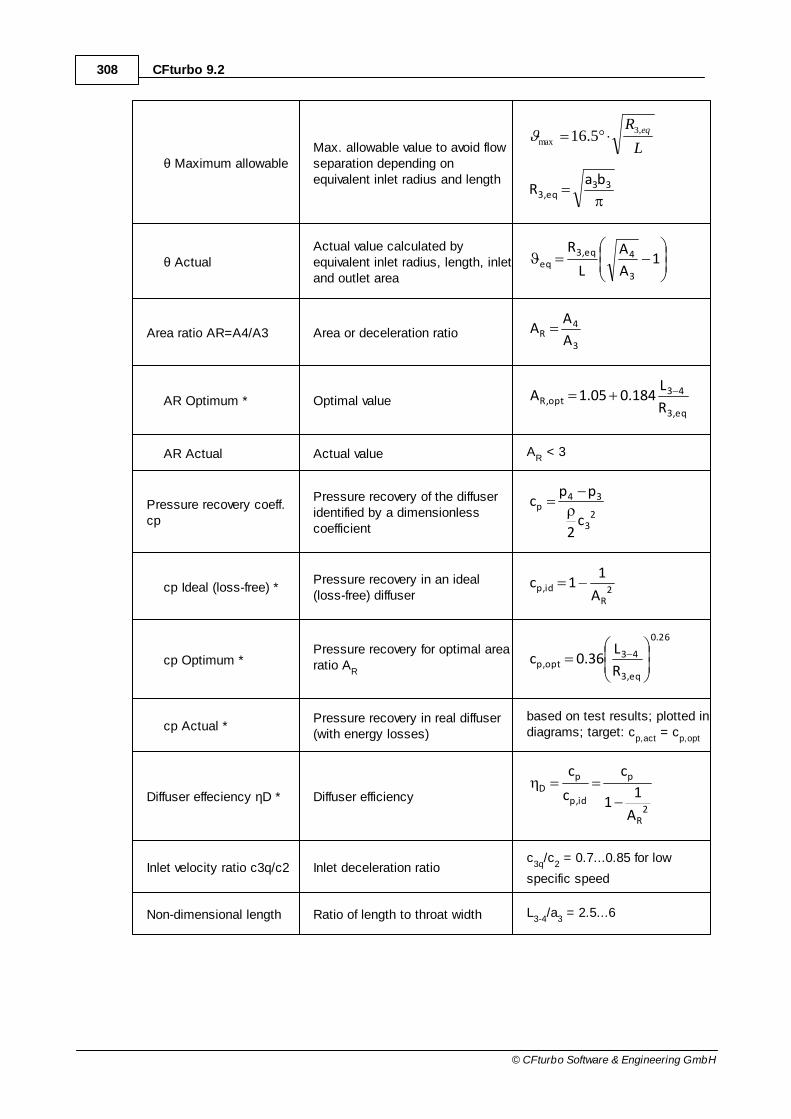
308 CFturbo 9.2
© CFturbo Software & Engineering GmbH
θ Maximum allowableMax. allowable value to avoid flowseparation depending onequivalent inlet radius and length
L
R eq,3
max 5.16
33eq,3
baR
θ ActualActual value calculated byequivalent inlet radius, length, inletand outlet area
1A
A
L
R
3
4eq,3eq
Area ratio AR=A4/A3 Area or deceleration ratio3
4R
A
AA
AR Optimum * Optimal valueeq,3
43opt,R
R
L184.005.1A
AR Actual Actual value AR < 3
Pressure recovery coeff.cp
Pressure recovery of the diffuseridentified by a dimensionlesscoefficient
23
34p
c2
ppc
cp Ideal (loss-free) *Pressure recovery in an ideal(loss-free) diffuser
2R
id,pA
11c
cp Optimum *Pressure recovery for optimal arearatio A
R
26.0
eq,3
43opt,p
R
L36.0c
cp Actual *Pressure recovery in real diffuser(with energy losses)
based on test results; plotted indiagrams; target: c
p,act = c
p,opt
Diffuser effeciency ηD * Diffuser efficiency 2
R
p
id,p
pD
A
11
c
c
c
Inlet velocity ratio c3q/c2 Inlet deceleration ratioc
3q/c
2 = 0.7...0.85 for low
specific speed
Non-dimensional length Ratio of length to throat width L3-4
/a3 = 2.5...6

309Stator
© CFturbo Software & Engineering GmbH
L34/a3
Throat aspect ratio b3/a3 Ratio of inlet width to throat width b3/a
3 = 0.8...2
Outlet rel. kin. energy *Kinetic energy of diffuser outlet; tominimize losses in the overflowchannels of multistage machines
04.002.0gH2
c
opt
24
Velocity ratio c4/c1m *Ratio of outlet velocity to inletvelocity of downstream impeller ofmultistage machines
c4/c
m1 = 0.85...1.25
* for radial diffusers of pumps only
9.5 Blade profiles
? Stator | Blade profile
In principle, the same features are available as for the blade profiles of impellers.
For the special radial diffuser blade shapes "Log. Spiral + Straight 2D" and "Circular + Free-form 2D"the blade thickness is added to one side of the mean line only (see Mean line ).
For radial diffusers the same informational values as in the mean line design are displayed in theInfo area. The reason is the influence of the blade thickness to these numbers.
9.6 Blade edges
? Stator | Blade edges
In principle, the same features are available as for the blade edges of impellers.
9.7 CFD Setup
? Stator | CFD Setup
In principle, the same features are available as for the CFD setup of impellers.
270
306
306
274
280

310 CFturbo 9.2
© CFturbo Software & Engineering GmbH
9.8 Model settings
? Stator | Model settings
In principle, the same features are available as for the model settings of impellers.
9.9 Model finishing
? Stator | Model finishing
In principle, the same features are available as for the model finishing of impellers.
288
290
Part
X
312 CFturbo 9.2
© CFturbo Software & Engineering GmbH
10 Volute
? Volute
This chapter describes in detail the design process for volute type componentsfeatured in CFturbo.
The content reflects the design steps in the sequence they are encounteredduring the design process.
Design steps
Inlet definition
Cross section
Spiral development areas
Diffuser
Cut-water
Model settings
CFD setup
10.1 Setup & Inlet
? Volute | Setup + Inlet
The first design step of the volute is to define the inlet side. It consits of 2 steps:
(1) Setup
(2) Inlet details
312
316
327
333
340
349
349
314
316

313Volute
© CFturbo Software & Engineering GmbH
On right panel Information onpage Meridian you can find ameridional preview (z, r) of thedesigned volute inlet.
The outlet of the upstreamcomponent is representedschematically in gray, the interfaceposition in brown.
Auto fit view results in automaticscaling of the diagram if geometricalvalues are changing.

314 CFturbo 9.2
© CFturbo Software & Engineering GmbH
10.1.1 Setup
On page Setup you can define some general properties used for the spiral design.
Volute type
Single volute (default)This simple type is commonly used and has a single cut-water.
Double voluteA second cut-water (splitter) is designed in order to reduce the radial forces.
Design flow rate
Volumetric efficiency ηv (default: 1.0)
to consider any internal volumetric losses (recirculation)
Flow factor FQ (default: 1.0)
for over dimensioning, particularly for better efficiency at overload operation

315Volute
© CFturbo Software & Engineering GmbH
Spiral inlet
Inlet diameter dIn
(d4)
Inlet width bIn
(b4)
dIn
and bIn
are suitable to the previous component outlet. If the previous component is an impeller d4
and b4 are determined using the ratios d
4/d
2 and b
4/b
2, which are calculated from functions
dependent on the specific speed nq (see Approximation function ).
Clicking on the Calculate-button, to the top right, recalculates the standard values.
A short distance between the impeller and the cut-water is desirable for reasons of flow. For acousticand vibration reasons, however, a certain minimum distance is necessary. The inlet width b
4 should
be chosen such that the width/height ratio at the end cross-section of the volute is close to 1. Theratio b
4/b
2 can be varied within a relatively wide range without significant negative effect on the
efficiency. For radial impellers with open impeller sides, values up to b4/b
2=2 are possible. At higher
specific speeds (wider impellers), however, high width ratios have a negative effect on flow (intensivesecondary flows, turbulence losses). In this case, b
4/b
2 should be between 1.05 and 1.2.
Values dIn
and bIn
are coupled to the corresponding interface values .
Information
Various calculated values are shown, for information purposes, on the right side (Values):
Calculated internal flow rate Qi VQi QFQ
Inlet diameter ratio dIn
/d2
Inlet width ratio bIn
/b2
Inlet meridional velocity cm
Inlet circumferential velocity cu
Inlet velocity c
124
316
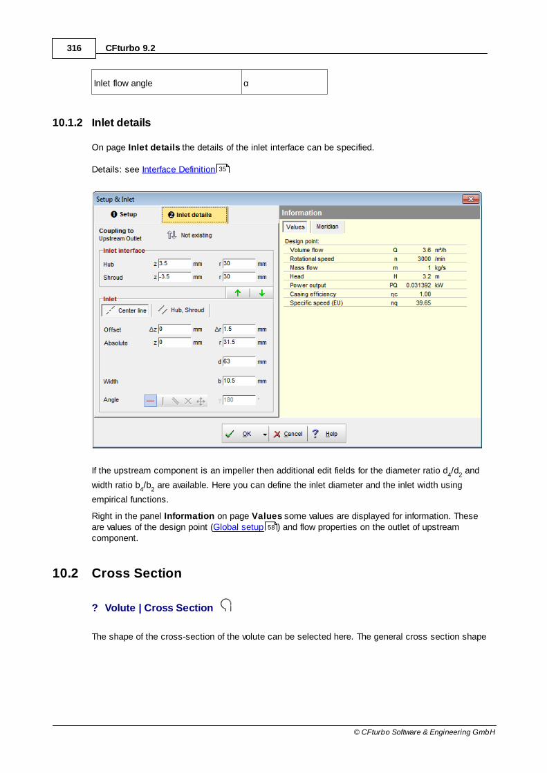
316 CFturbo 9.2
© CFturbo Software & Engineering GmbH
Inlet flow angle α
10.1.2 Inlet details
On page Inlet details the details of the inlet interface can be specified.
Details: see Interface Definition
If the upstream component is an impeller then additional edit fields for the diameter ratio d4/d
2 and
width ratio b4/b
2 are available. Here you can define the inlet diameter and the inlet width using
empirical functions.
Right in the panel Information on page Values some values are displayed for information. Theseare values of the design point (Global setup ) and flow properties on the outlet of upstreamcomponent.
10.2 Cross Section
? Volute | Cross Section
The shape of the cross-section of the volute can be selected here. The general cross section shape
35
58

317Volute
© CFturbo Software & Engineering GmbH
is illustrated whereas the radial extension is assumed (radial scaling can be modified above thediagram).
In general, very small cross-sections width should be avoided. The achievable cross-section shapestrongly depends on manufacturing and the available space.
Sections
The table contains the cross section definitions (minimum 1 cross section). Each cross section isdefined by:
the circumferential position: angle φ
(de)activation by selecting the checkbox on the left side
cross section type on the left side
optional cross section type on the right side or symmetric
Between 2 neighboring cross section definitions a smooth transition is realized.
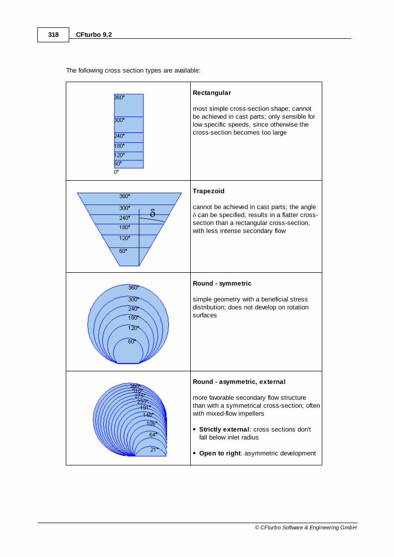
318 CFturbo 9.2
© CFturbo Software & Engineering GmbH
The following cross section types are available:
Rectangular
most simple cross-section shape; cannotbe achieved in cast parts; only sensible forlow specific speeds, since otherwise thecross-section becomes too large
Trapezoid
cannot be achieved in cast parts; the angle can be specified; results in a flatter cross-
section than a rectangular cross-section,with less intense secondary flow
Round - symmetric
simple geometry with a beneficial stressdistribution; does not develop on rotationsurfaces
Round - asymmetric, external
more favorable secondary flow structurethan with a symmetrical cross-section; oftenwith mixed-flow impellers
Strictly external: cross sections don'tfall below inlet radius
Open to right: asymmetric development
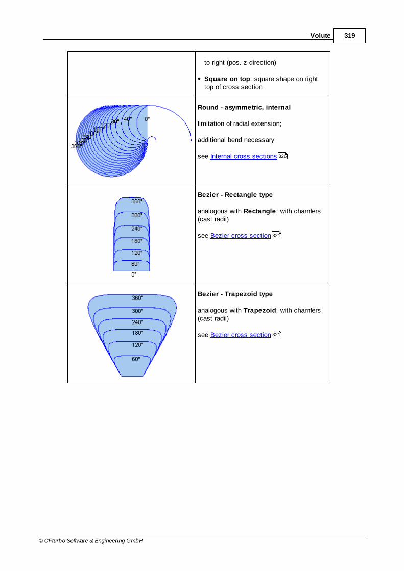
319Volute
© CFturbo Software & Engineering GmbH
to right (pos. z-direction)
Square on top: square shape on righttop of cross section
Round - asymmetric, internal
limitation of radial extension;
additional bend necessary
see Internal cross sections
Bezier - Rectangle type
analogous with Rectangle; with chamfers(cast radii)
see Bezier cross section
Bezier - Trapezoid type
analogous with Trapezoid; with chamfers(cast radii)
see Bezier cross section
326
321
321

320 CFturbo 9.2
© CFturbo Software & Engineering GmbH
Line segments
see Line Segments cross section
Radius based
see Radius based cross section
Section properties
Here you can specify some properties of the currently selected cross section in the table Sections.
Details can be found in the table above.
Display options
Under Display options, changes can be made which affect only the graphics.
Limitations
For double volutes the cone angle (opening) of all cross sections has to be constant. Therefore roundtypes and Line segments are not available.
If any of these impossible cross section types are already part of the project then they are converted
322
325

321Volute
© CFturbo Software & Engineering GmbH
automatically when selecting the double volute type (see Setup & Inlet ). The following messagewill be displayed:
"Volute section type(s) were modified due to double volute requirements."if any cross section type was modified automatically
"Cone angle(s) were modified due to double volute requirements."if the cone angle of any cross section was adapted automatically
10.2.1 Bezier cross section
The shape of a Bezier cross-section is described by a Bezier curve.
One half of the shape of the cross-section is described using a 4th degree Bezier polynomial. Points0 and 4 are the end points and cannot be changed. Point 1 can be moved along a straight line whichcorresponds to the cone angle of the cross-section (0° for a rectangle type, for a trapezoid type).Point 3 can only be moved in the horizontal direction in order to guarantee a smooth transitionbetween the two symmetrical halves. The intersection of the two lines which points 1 and 3 are on isdesignated by the letter S and plays an important role in the positioning of Bezier points 1 and 3.Point 2 can be moved freely and therefore he has the major influence on the shape of the cross-section. In the first design, point 2 is identical with point S.
Two basic shapes of the cross-section can be selected, rectangular or trapezoid. Only the endcross-section of the volute is designed, all other cross-sections result from this. Under the heading Inner point position, you can select whether positioning of the inner points 1 and 3 should berelative (0..1; 0=point 0/4; 1=point S) or absolute (distance from point S). The numeric values ofthe positions can be changed by right-clicking on points 1 or 3. If the option Show all points under
312

322 CFturbo 9.2
© CFturbo Software & Engineering GmbH
the heading Options is selected, the different positioning methods become apparent.
The minimum curvature radius of the designed contour is shown in the box to the bottom right.
10.2.2 Line Segments cross section
The shape of a Line segments cross-section is described by a series of line segments.
One half of the shape of the cross-section is initially based on line segments arranged in a trapezoidshape. Points 1 and 4 are the fix start- and endpoint.
All corner points are connected by line segments. The coordinates of each point and the relatedcorner radius can be adjusted in the context dialog:

323Volute
© CFturbo Software & Engineering GmbH
Coordinates and radius of vertex
Using the context menu of a line segment, points can be added at the cursor position or beremoved:
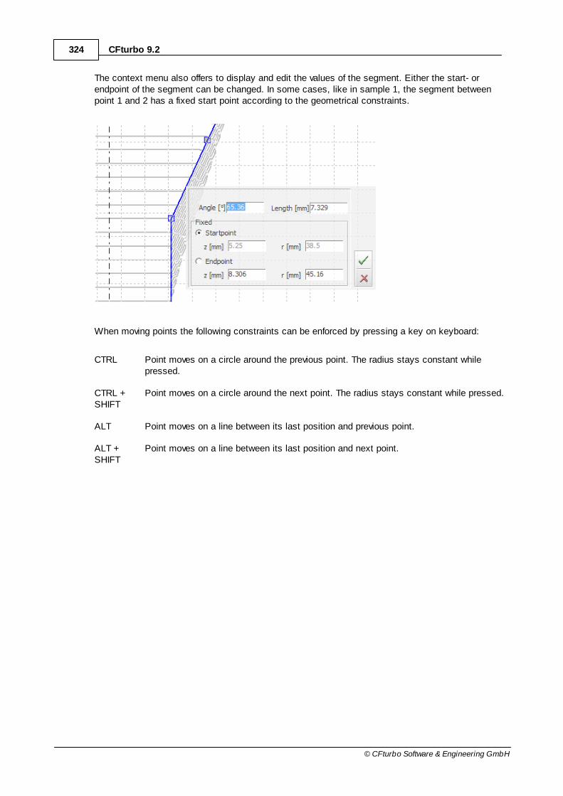
324 CFturbo 9.2
© CFturbo Software & Engineering GmbH
The context menu also offers to display and edit the values of the segment. Either the start- orendpoint of the segment can be changed. In some cases, like in sample 1, the segment betweenpoint 1 and 2 has a fixed start point according to the geometrical constraints.
When moving points the following constraints can be enforced by pressing a key on keyboard:
CTRL Point moves on a circle around the previous point. The radius stays constant whilepressed.
CTRL +SHIFT
Point moves on a circle around the next point. The radius stays constant while pressed.
ALT Point moves on a line between its last position and previous point.
ALT +SHIFT
Point moves on a line between its last position and next point.

325Volute
© CFturbo Software & Engineering GmbH
10.2.3 Radius based cross section
The shape of a radius based cross section is described by straight lines and circular arcs.
The geometry is described by the following parameters:
base height h height of the radial base part
base radius RB
rounding between base part and cone part(radius can be limited due to length of base part and conepart)
opening angle δ angle of the cone part
corner radius RC
rounding between cone part and main circular arc on top(radius can be limited due to length of cone part and circulararc on top)
main radius R radius of main circular arc on top

326 CFturbo 9.2
© CFturbo Software & Engineering GmbH
10.2.4 Internal cross sections
Internal volutes are limited in its radial and axial extensions (see gray lines in the picture).
The additional bend can be described by the following parameters:
Neck width side distance from volute inlet to actual volute crosssections
Inner bend shape shape of the inner bend wall
Ratio semiaxis ratio for quarter bend
Outer bend shape shape of the outer bend wall
Bend area ratio ratio of outlet to inlet section of the bend

327Volute
© CFturbo Software & Engineering GmbH
10.3 Spiral development areas
? Volute | Spiral development areas
The spiral development areas can be designed and calculated in this dialog box.
General
The spiral development areas can be calculated manually by pressing the Calculate spiral buttonor automatically if the Automatic check box is selected.
The manual calculation freezes the radial extension of the currently designed cross sections (redcontour curves in the main diagram on the left side).Any modifications of the Inlet definition or the Cross section shape result in updated crosssections while keeping the radial extension of each section constant.All modifications in this dialog are not considered as long as the Calculate spiral button is notpressed.
312 316
328 CFturbo 9.2
© CFturbo Software & Engineering GmbH
The automatic mode updates the cross sections completely if anything was modified in the Inletdefinition or the Cross section dialog.Furthermore all modifications in this dialog are considered directly by updating all cross sectionscompletely.
Furthermore the wrap angle can be defined - default value is 360°.
Design rule
You can select the Design rule for volute calculation, whereas 3 possibilities exist: Pfleiderer,Stepanoff, Self.
Details Design Rule
Cut-water compensation
In panel Cut-water compensation you can specify parameters for the cut-water design.
Details Cut-water compensation
Display options
Under Display options, changes can be made which affect only the graphical presentation:
Show – refers to the main diagram with volute contour
Section lines radial angle lines
Cut-water compensation cut-water compensation as a larger inner radius
Show in cross section – refers to the cross-section diagram
Cut-water section cut-water cross-section
Equivalent diameter (outlet) equivalent diameter (dashed line)
Filled cross sections filled cross-sections
Possible warnings
312 316
330 330
331
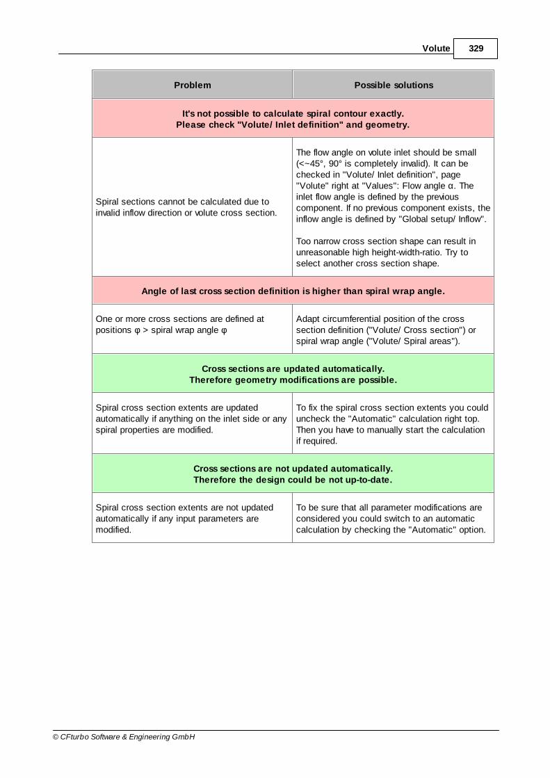
329Volute
© CFturbo Software & Engineering GmbH
Problem Possible solutions
It's not possible to calculate spiral contour exactly.Please check "Volute/ Inlet definition" and geometry.
Spiral sections cannot be calculated due toinvalid inflow direction or volute cross section.
The flow angle on volute inlet should be small(<~45°, 90° is completely invalid). It can bechecked in "Volute/ Inlet definition", page"Volute" right at "Values": Flow angle α. Theinlet flow angle is defined by the previouscomponent. If no previous component exists, theinflow angle is defined by "Global setup/ Inflow".
Too narrow cross section shape can result inunreasonable high height-width-ratio. Try toselect another cross section shape.
Angle of last cross section definition is higher than spiral wrap angle.
One or more cross sections are defined atpositions φ > spiral wrap angle φ
Adapt circumferential position of the crosssection definition ("Volute/ Cross section") orspiral wrap angle ("Volute/ Spiral areas").
Cross sections are updated automatically.Therefore geometry modifications are possible.
Spiral cross section extents are updatedautomatically if anything on the inlet side or anyspiral properties are modified.
To fix the spiral cross section extents you coulduncheck the "Automatic" calculation right top.Then you have to manually start the calculationif required.
Cross sections are not updated automatically.Therefore the design could be not up-to-date.
Spiral cross section extents are not updatedautomatically if any input parameters aremodified.
To be sure that all parameter modifications areconsidered you could switch to an automaticcalculation by checking the "Automatic" option.

330 CFturbo 9.2
© CFturbo Software & Engineering GmbH
10.3.1 Design rule
The flow rate through a cross-section, A, of the circumferential angle, , is generally calculated as:
)(r
r
uu
a
4
dr)r(bcdAcQ
Using 2QQ i
results in an equation to calculate the circumferential angle, , dependenton the outer radius r
a:
)(r
r
ui
a
4
dr)r(bcQ
2
b(r) is a geometrical function which is defined according to the shape of the cross-section. Thevelocity c
u is chosen in accordance with the design instructions. Under Design rule, two
alternatives can be selected.
1. Pfleiderer
Experience has shown that the losses can be greatly minimised if the volute housing is dimensionedsuch that the fluid flows in accordance with the principal of conservation of angular momentum. Thecross-section areas are therefore designed in accordance with the principal of conservation ofangular momentum, i.e. angular momentum exiting the impeller is constant. In addition, an exponent
of angular momentum, x, can be chosen so that the principle curx = const. is obeyed. When x=1,
the angular momentum is constant. For the extreme of x=0, the circular component of the absolutevelocity cu remains constant at the impeller outlet.
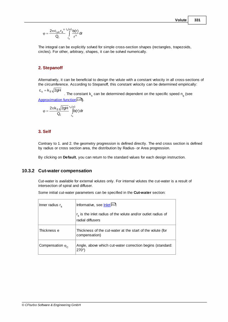
331Volute
© CFturbo Software & Engineering GmbH
)(r
rx
i
x44u
a
4
drr
)r(b
Q
rc2
The integral can be explicitly solved for simple cross-section shapes (rectangles, trapezoids,circles). For other, arbitrary, shapes, it can be solved numerically.
2. Stepanoff
Alternatively, it can be beneficial to design the volute with a constant velocity in all cross-sections ofthe circumference. According to Stepanoff, this constant velocity can be determined empirically:
gH2kc Su. The constant k
s can be determined dependent on the specific speed n
q (see
Approximation function ).
)(r
ri
Sa
4
dr)r(bQ
gH2k2
3. Self
Contrary to 1. and 2. the geometry progression is defined directly. The end cross section is definedby radius or cross section area, the distribution by Radius- or Area progression.
By clicking on Default, you can return to the standard values for each design instruction.
10.3.2 Cut-water compensation
Cut-water is available for external volutes only. For internal volutes the cut-water is a result ofintersection of spiral and diffuser.
Some initial cut-water parameters can be specified in the Cut-water section:
Inner radius r4
Informative, see Inlet
r4 is the inlet radius of the volute and/or outlet radius of
radial diffusers
Thickness e Thickness of the cut-water at the start of the volute (forcompensation)
Compensation C
Angle, above which cut-water correction begins (standard:270°)
124
312

332 CFturbo 9.2
© CFturbo Software & Engineering GmbH
The cut-water does disturb the flow, since thecross-section of the flow is narrowed suddenly bythe thickness of the cut-water.
To weaken this negative influence, the cut-watercan be corrected. This is achieved by assumingthat from the angle
C the inner radius r
4
increases linearly to a value of r4+e at the end
cross-section of the volute. This results in largervolute cross-sections in this area, so that thenarrowing of flow caused by the cut-waterbecomes less significant.
By clicking on Default, you can return to thestandard values for the cut-water.
10.3.3 Additional views
The following informationcan be displayed in thespiral dialog using the"Additional views" button:
3D-Preview
3D model of the currently designed spiral development areas.
Informational values
Some informative values relating to the end cross-section are displayed:
150
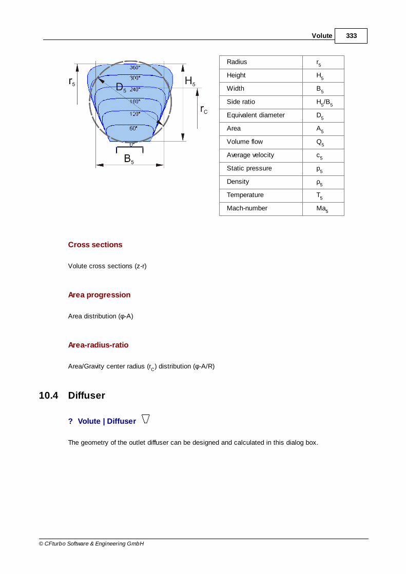
333Volute
© CFturbo Software & Engineering GmbH
Radius r5
Height H5
Width B5
Side ratio H5/B
5
Equivalent diameter D5
Area A5
Volume flow Q5
Average velocity c5
Static pressure p5
Density ρ5
Temperature T5
Mach-number Ma5
Cross sections
Volute cross sections (z-r)
Area progression
Area distribution (φ-A)
Area-radius-ratio
Area/Gravity center radius (rC) distribution (φ-A/R)
10.4 Diffuser
? Volute | Diffuser
The geometry of the outlet diffuser can be designed and calculated in this dialog box.

334 CFturbo 9.2
© CFturbo Software & Engineering GmbH
Direction
In general, 3 basic shapes are available:
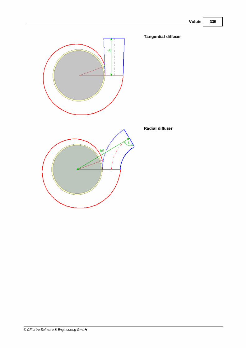
335Volute
© CFturbo Software & Engineering GmbH
Tangential diffuser
Radial diffuser
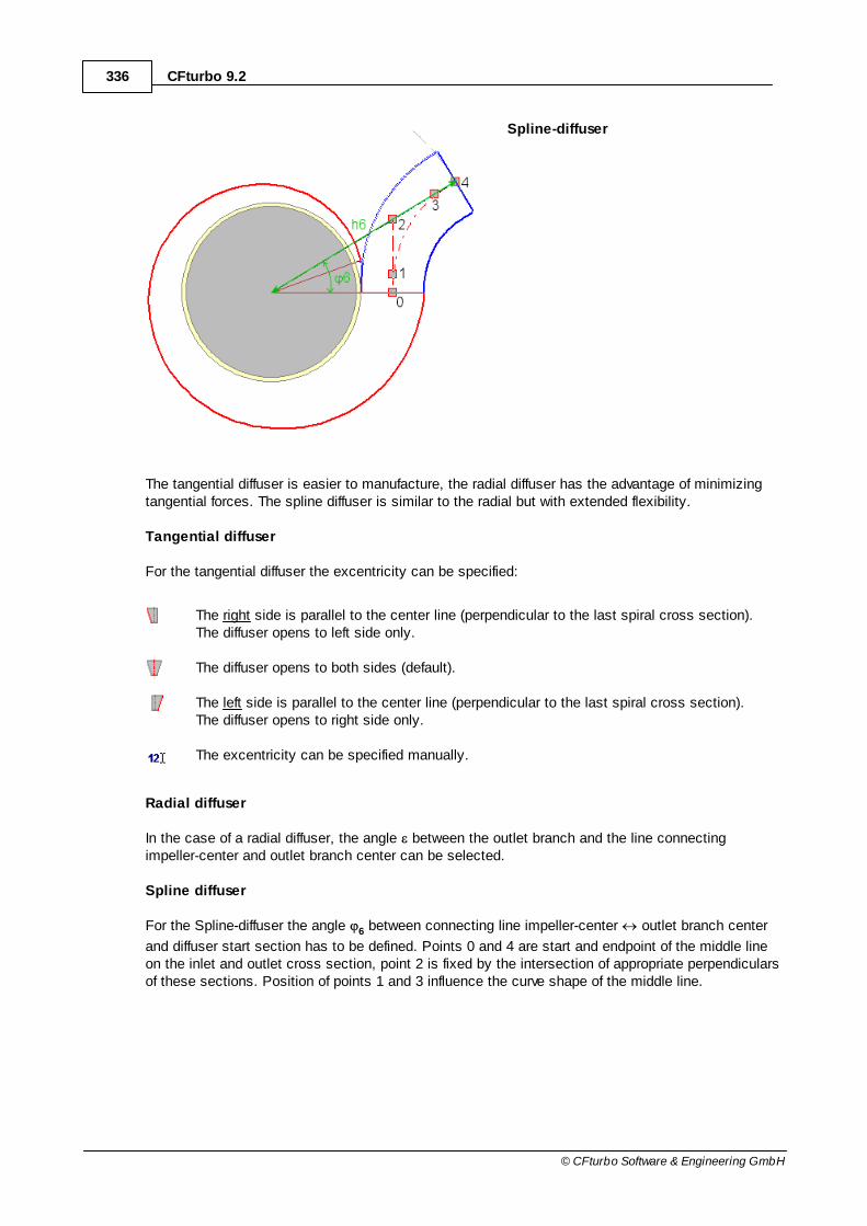
336 CFturbo 9.2
© CFturbo Software & Engineering GmbH
Spline-diffuser
The tangential diffuser is easier to manufacture, the radial diffuser has the advantage of minimizingtangential forces. The spline diffuser is similar to the radial but with extended flexibility.
Tangential diffuser
For the tangential diffuser the excentricity can be specified:
The right side is parallel to the center line (perpendicular to the last spiral cross section).The diffuser opens to left side only.
The diffuser opens to both sides (default).
The left side is parallel to the center line (perpendicular to the last spiral cross section).The diffuser opens to right side only.
The excentricity can be specified manually.
Radial diffuser
In the case of a radial diffuser, the angle between the outlet branch and the line connectingimpeller-center and outlet branch center can be selected.
Spline diffuser
For the Spline-diffuser the angle 6 between connecting line impeller-center outlet branch center
and diffuser start section has to be defined. Points 0 and 4 are start and endpoint of the middle lineon the inlet and outlet cross section, point 2 is fixed by the intersection of appropriate perpendicularsof these sections. Position of points 1 and 3 influence the curve shape of the middle line.

337Volute
© CFturbo Software & Engineering GmbH
By clicking on Default, you can return to the default values for the diffuser geometry.
Dimensions
The extension of the diffuser can be defined in panel Dimensions. Parameters in the x,y-plane canbe specified, as well as a rake of the diffuser in z-direction.
For all diffuser shapes the extension isdefined by the diffuser height h6, which is the
distance from the diffuser outlet to a parallelline through the center point.
The distance C6 from the h6-line to the center
point is displayed for information, both in thediagram and numerical in the Informationpanel.
Additionally the starting position of the diffuser is defined by the angle 0, whereas 0° is horizontal
right. The whole volute can be rotated by this value. By using the button Vertical outflow directionthe volute can be rotated for vertical direction of the pressure joint.
The diffuser bending in z-direction is described by the parameters shown in the sketch.
There exist 2 straight segments 1, 3 and a circular segment 2. The lengths L1, L2 and L3 are
specified as percentage.
The curvature is defined by the radius R, the direction by the angle α.
The z-bend is illustrated in the diagram by a green center line.

338 CFturbo 9.2
© CFturbo Software & Engineering GmbH
End cross-section
The end cross-section of the diffuser can be either round or rectangular. The diameter D6 can be
directly defined or selected from standard tables. In the case of a rectangular end cross-section theheight H6 and width B6 can be chosen.
Furthermore, the percental position (Position of end shape) can be specified, where the shape ofthe end cross section is reached (default = 100%). Afterwards the shape is constant and the crosssection area is changing only.
Display options
Under Display options, changes can be made which affect only the graphics.

339Volute
© CFturbo Software & Engineering GmbH
10.4.1 Additional views
The following informationcan be displayed in thediffuserl dialog using the"Additional views" button:
3D-Preview
3D model of the currently designed diffuser geometry.
Informational values
Some informative values are displayed:
Equivalent diameter DIN Diameter of the equivalent circle at the diffuserinlet
Equivalent diameter DOUT Diameter of the equivalent circle at the diffuseroutlet
Area AIN Area at diffuser inlet
Area AOUT Area at diffuser outlet
Deceleration ratio AR 26
25R DDA
Length L Length of the diffuser
Angle to middle Angle between connecting line impeller-center outlet branch center and diffuser start section
Center distance C Distance from the h6-line to the center point
Cone angle Cone angle from D5 to D
6 over the length L
Diffusor radius R Radius of middle line (for radial diffuser only)
150

340 CFturbo 9.2
© CFturbo Software & Engineering GmbH
Cross section
Volute cross sections (z-r)
Area progression
Area distribution (l-A)
10.5 Cut-water
? Volute | Cut-water
The geometry of the cut-water can be designed in this dialog box.
Generally, the cut-water can be designed in three modes: Simple , Fillet or Sharp .343 345 348
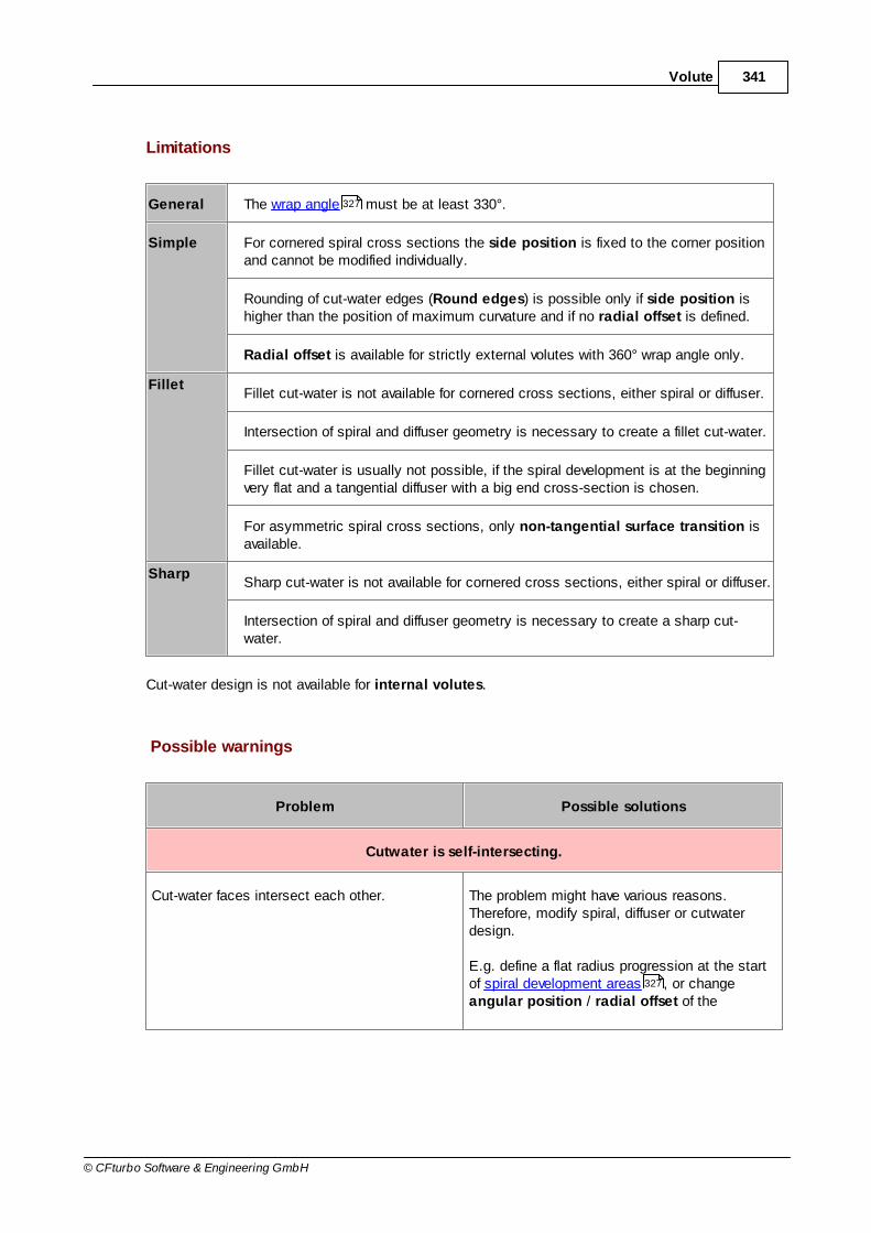
341Volute
© CFturbo Software & Engineering GmbH
Limitations
General The wrap angle must be at least 330°.
Simple For cornered spiral cross sections the side position is fixed to the corner positionand cannot be modified individually.
Rounding of cut-water edges (Round edges) is possible only if side position ishigher than the position of maximum curvature and if no radial offset is defined.
Radial offset is available for strictly external volutes with 360° wrap angle only.
FilletFillet cut-water is not available for cornered cross sections, either spiral or diffuser.
Intersection of spiral and diffuser geometry is necessary to create a fillet cut-water.
Fillet cut-water is usually not possible, if the spiral development is at the beginningvery flat and a tangential diffuser with a big end cross-section is chosen.
For asymmetric spiral cross sections, only non-tangential surface transition isavailable.
SharpSharp cut-water is not available for cornered cross sections, either spiral or diffuser.
Intersection of spiral and diffuser geometry is necessary to create a sharp cut-water.
Cut-water design is not available for internal volutes.
Possible warnings
Problem Possible solutions
Cutwater is self-intersecting.
Cut-water faces intersect each other. The problem might have various reasons.Therefore, modify spiral, diffuser or cutwaterdesign.
E.g. define a flat radius progression at the startof spiral development areas , or changeangular position / radial offset of the
327
327

342 CFturbo 9.2
© CFturbo Software & Engineering GmbH
Problem Possible solutions
cutwater.
3D-Error: Could not create bounded surface for Cut-water.Patch!
Parameter side position is disadvantageous.The side position should not be too low whenedges are rounded.
3D-Error: Could not create fillet for Cut-water! Possibly, the fillet radius is too large.
[for asymmetric volutes]
Fillet cannot be created because intersectioncurve of spiral and diffuser is wavy.
Modify the Position of end shape in theDiffuser dialog to avoid wavy intersection curve.
[for asymmetric volutes]
Fillet cannot be created because intersectioncurve of spiral and diffuser is tangential to thesharp diffuser edge.
Modify Spiral start position
338
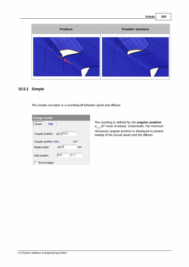
343Volute
© CFturbo Software & Engineering GmbH
Problem Possible solutions
10.5.1 Simple
The simple cut-water is a rounding-off between spiral and diffuser.
The rounding is defined by the angular position
C,0 (0°=start of volute). Underneath, the minimum
necessary angular position is displayed to preventoverlap of the actual volute and the diffuser.

344 CFturbo 9.2
© CFturbo Software & Engineering GmbH
Additionally, the diffuser can beshifted in radial direction by the radial offset ∆r
C to reduce the
intersection of spiral and diffuser.This radial offset corresponds tothe cut-water thickness.
Side position defines thetransition position from the centralrounding surface to the sidesurfaces. For asymmetric spiralcross sections two independentvalues can be specified for left andright side.
The created edge can be roundedoptionally (Round edges).

345Volute
© CFturbo Software & Engineering GmbH
The cut-water itself is designed by a 4th order Bezier curve. The shape can be modified interactivelyafter zooming in (Zoom Cut-water).
10.5.2 Fillet
For fillet cut-water design the spiral and the diffuser are trimmed and rounded at their intersectioncurve.
Prerequisites:
The wrap angle must be high enough so that spiral and diffuser intersect.327

346 CFturbo 9.2
© CFturbo Software & Engineering GmbH
The corresponding fillet radius can be specified.
Additionally, the Diffuser base form factor defines theroundness of the first diffuser cross section on its baseside and is between 0.2 and 1:
0 = cornered base side (like spiral section)
1 = full rounded base side
The factor affects the shape of the intersection curveand therefore the shape of the cut-water.
Diffuser base form factor for a round spiral cross section

347Volute
© CFturbo Software & Engineering GmbH
Compares diffuser base form factor of 0.2 and 1.0 for a spiral cross section of type line segments
The Spiral start position indicates the angular position at which the spiral begins and influencesthe intersection of spiral and diffuser. It has to be at least 1° and must be lower than the intersectionposition of spiral and diffuser. If Automatic is activated the optimal angular position is determinedautomatically.
The Surface transition defines the transition from the side patch surfaces to the central filletsurface:
Tangential: Tangential transition between both surfaces (Time-consuming)
Non-tangential: No tangential transition between both surfaces
Automatic: Tries tangential transition. If it fails, a non-tangential transition is used. (Time-consuming)

348 CFturbo 9.2
© CFturbo Software & Engineering GmbH
If the fillet cut-water mode has beenchosen, the 3D-model is set to themodel state "Solids only" afterevery update of the design becauseonly then the spiral and diffusersurfaces that are trimmed according tothe fillet are visible.
10.5.3 Sharp
For sharp cut-water design the spiral and the diffuser are trimmed only at their intersection curve.The resulting geometry can be processed in the CAD system.
Prerequisites:
The wrap angle must be high enough so that spiral and diffuser intersect.
160
327

349Volute
© CFturbo Software & Engineering GmbH
10.6 CFD Setup
? Volute | Additional | CFD Setup
The designed geometry can be extended by virtual elements.
Through - flow areaInlet and outlet surface
RSI ConnectionIf a Rotor-Stator-Interface (RSI) is existing on the inlet side of the component, an existing gapcan be closed automatically by the RSI connection. These surfaces provide a simplified,closed volume model for flow simulation neglecting impeller side chambers or other casingparts.
These extensions are to be used for flow simulation (CFD) and are virtual only.
10.7 Model settings
? Volute | Model settings
On dialog Model settings you can specify how many data points are to be used for the 3D modeland for the point based export formats.
The number of points can be set for both cases separately for all geometry parts.
Spiral: cross sections, points per cross section
Diffuser: cross sections
Cutwater (sides): cross sections, points per cross section

350 CFturbo 9.2
© CFturbo Software & Engineering GmbH
The cutwater cross sections setting does not refer to the center face, because its sectioncount is determined by the number of points of the spiral and by the side position .
Presetting
Select from 3 global presettings.
Distance tolerance (3D Model)
The distance tolerance defines the maximum allowed distancebetween sewed surfaces, e.g the faces of a solid.
If it is too small, the solids cannot be created.
If it is too big, small faces are ignored when creating a solid.
Length unit for Export (Point Export)
331

351Volute
© CFturbo Software & Engineering GmbH
The length unit for the geometry export can be selected. Pleaseselect the appropriate units when importing data to the chosenCAD software.
When a new volute is created the model settings of the last opened volute are adopted.

Part
XI

353Appendix
© CFturbo Software & Engineering GmbH
11 Appendix
11.1 References
GENERAL
Willi Bohl, Wolfgang ElmendorfStrömungsmaschinen 1+2Vogel-Verlag, 2008
Werner FisterFluidenergiemaschinen Bd. 1 und 2Springer-Verlag, 1984 und 1986
Wolfgang KalideEnergieumwandlung in Kraft- und ArbeitsmaschinenHanser-Verlag, 1989
Carl Pfleiderer, Hartwig PetermannStrömungsmaschinenSpringer-Verlag, 1991
Joachim RaabeHydraulische Maschinen und AnlagenVDI-Verlag, 1989
Arnold Whitfield, Nicholas C. BainesDesign of Radial TurbomachinesLongman Scientific & Technical, 1990
PUMPS
Johann F. GülichKreiselpumpenSpringer-Verlag, 1999
Kurt Holzenberger, Klaus JungKreiselpumpen LexikonKSB AG, 1989
Val S. Lobanoff, Robert R. RossCentrifugal Pumps, Design & ApplicationGulf Professional Publishing, 1992
Michael SchwanseStrömungsmechanische Auslegung und Nachrechnung von radialen und diagonalenKreiselpumpenlaufrädern

354 CFturbo 9.2
© CFturbo Software & Engineering GmbH
Dissertation, TU Dresden, 1990
A. J. StepanoffCentrifugal and Axial Flow PumpsJohn Wiley & Sons, 1957
John TuzsonCentrifugal pump designJohn Wiley & Sons, 2000
Walter WagnerKreiselpumpen und KreiselpumpenanlagenVogel-Verlag, 1994
Gotthard WillKreiselpumpenin: Taschenbuch Maschinenbau, Band 5hrsg. von Hans-Joachim Kleinert, Verlag Technik Berlin, 1989
VENTILATORS
Leonhard Bommes, Jürgen Fricke, Reinhard GrundmannVentilatorenVulkan-Verlag, 2003
Bruno EckVentilatorenSpringer-Verlag, 1991
Thomas CarolusVentilatorenTeubner-Verlag, 2003
COMPRESSORS
Ronald H. AungierCentrifugal CompressorsASME Press, 2000
Klaus H. LüdtkeProcess Centrifugal CompressorsSpringer-Verlag, 2004
Bruno Eckert, Erwin SchnellAxial- und RadialkompressorenSpringer-Verlag, 1980
Davide Japikse

355Appendix
© CFturbo Software & Engineering GmbH
Centrifugal Compressors Design and PerformanceConcepts ETI, 1996
N. A. CumpstyCompressor aerodynamicsKrieger publishing, 2004
Ernst LindnerTurboverdichterin: Taschenbuch Maschinenbau, Band 5hrsg. von Hans-Joachim Kleinert, Verlag Technik Berlin, 1989
TURBINES
Ronald H. AungierTurbine AerodynamicsASME Press, 2006
Hany Moustapha, Mark Zelesky, Nicholas C. Baines, Davide JapikseAxial and Radial TurbinesConcepts NREC, 2003
Further literature
John D. Stanitz, Vasily D. PrianA rapid approximate method for the determining velocity distribution on impeller blades of centrifugalcompressorsNACA Technical note 2421; July 1951
John David Anderson, R. Grundmann, E. DickComputational Fluid Dynamics: An IntroductionSpringer-Verlag, 1996
Redlich, O., Kwong, J.N.S.On the Thermodynamics of Solutions. V. An Equation of State. Fugacities of Gaseous Solutions,Chemical Reviews. 44, No. 1, pp. 233–244, 1949
Aungier, R.H.A Fast, Accurate Real Gas Equation of State for Fluid Dynamic Analysis Applications,Journal of Fluids Engineering, Vol. 117, pp. 277-281, 1995
Giorgio SoaveEquilibrium constants from a modified Redlich-Kwong equation of state.,Chemical Engineering Science. 27, No. 6, pp. 1197–1203, 1972
Peng, D.Y., Robinson, D.B.

356 CFturbo 9.2
© CFturbo Software & Engineering GmbH
A New Two-Constant Equation of State,Industrial and Engineering Chemistry: Fundamentals, Vol. 15: pp. 59–64, 1976
11.2 Symbols
Symbol Description
α Angle of absolute flow to u
β Angle of relative flow to u
δ Deviation angle flow / blade
δr
Swirl number
τ Obstruction of flow channel by blades
ω Angular velocity
ρ Density
η Efficiency
ψ Pressure coefficient
σ Thickness in circumferential direction; Speed coefficient
φ Wrap angle; Flow coefficient
A Cross section area
b Width
c Absolute velocity
cm
Meridional velocity (cm
=wm
)
cu
Circumferential component of absolute velocity
d Diameter
F Force
h Enthalpy
H Pump head
i Incidence angle

357Appendix
© CFturbo Software & Engineering GmbH
Symbol Description
L Length
M Torque
m Mass flow
N Number of revolutions
nq, N
sSpecific speed
p Pressure
P Power
Q Flow rate
r, R Radius
s Orthogonal thickness
S Static moment
u Circumferential velocity (Rotational speed)
v Velocity
wu
Circumferential component of relative velocity (wu+c
u=u)
w Relative velocity
Y Specific energy
z Geodetic height; Number of blades
11.3 Contact addresses
Development, Sales, Support
CFturbo Software & Engineering GmbHwww.cfturbo.com
Unterer Kreuzweg 1

358 CFturbo 9.2
© CFturbo Software & Engineering GmbH
01097 Dresden, Germany
Phone: (+49) 351 40 79 04 79Fax: (+49) 351 40 79 04 80
Friedrichstraße 2080801 Munich, Germany
Phone: (+49) 89 189 41 45 0Fax: (+49) 89 189 41 45 20
11.4 License agreement
Software Cession and Maintenance Contract
between
CFturbo Software & Engineering GmbH
Unterer Kreuzweg 1, 01097 Dresden (Germany)
- hereinafter designated the 'Licensor' -
and
the CFturbo user
- hereinafter designated the 'User' -
§ 1 LICENSE AGREEMENT
By virtue of this agreement, the User acquires from the Licensor the non-transferable and non-exclusive right to use the software 'CFturbo' (hereinafter designated the 'Software') for a period oftime, in exchange for the licence fee agreed between the Licensor and the User.
1. Licence Object

359Appendix
© CFturbo Software & Engineering GmbH
The User acquires a nodelocked license or a license for one local office network (LAN) at onedistinguished location of the company.
The program package consists of a data medium (CD-ROM or DVD) with the Software and a usermanual in the form of a PDF file. In the event that the Software was downloaded from the officialwebsite of the Licensor, the program package consists of the corresponding installation file includingelectronic documentation.
2. Duration / commencement of the licence
The User obtains the right to use the Software. The right is obtained after the payment of the fulllicence fee and implicitly expires at the end of the arranged time period.
4. Right of Use
(1) In accordance with this contract, the Licensor grants the User a right of use to the Softwaredescribed under 1. as well as a right to use the necessary printed matter and documentation. Theprinting-out of the manual for the purposes of working with the Software is permitted.
(2) The User may duplicate the Software only insofar as the duplication in question is necessary forthe use of the Software. Necessary reasons for duplication notably include the installation of theSoftware from the original data medium onto the mass storage of the hardware used, as well as theloading of the Software into the RAM memory.
(3) The User is entitled to perform duplication for backup purposes. However, in principle, only asingle backup copy may be created and stored. The backup copy must be labelled as being abackup copy of the ceded Software.
(4) If, for reasons of data security or the assurance of a fast reactivation of the computer system aftera total failure, the regular backing-up of the entire dataset including the computer programs used isessential, then the User may create the number of backup copies which are compulsorily required.The data media concerned must be labelled accordingly. The backup copies may only be used forpurely archival purposes.
(5) The User is obliged to take appropriate measures to prevent the unauthorized access of thirdparties to the program including its documentation. The supplied original data media, as well as thebackup copies, must be stored in a location protected against the unauthorized access of thirdparties. The employees of the User must be explicitly encouraged to observe these contractualconditions as well as the provisions of copyright law.
(6) Additional duplications, also including the printing-out of the program code on a printer, must notbe created by the User. The copying and the handover or transfer of the user manual to third partiesis not permitted.
5. Multiple Use and Networks

360 CFturbo 9.2
© CFturbo Software & Engineering GmbH
(1) The User may use the Software on any hardware available to him, provided that this hardware isappropriate for the use according to the Software documentation. In the event of changing thehardware, the Software must be erased from the previously used hardware.
(2) The simultaneous reading in, storage or use on more than one hardware device is not permittedunless the User has acquired multiple-use licences or network licences. Should the User wish touse the Software on multiple hardware configurations at the same time, for example to permit theuse of the Software by several employees, he must purchase the corresponding number of licences.
(3) The use of the ceded Software on different computers on a network or another multiple-workstation computer system is permitted, provided that the User has purchased multiple-uselicences or network licences. If this is not the case, the User may only use the Software on anetwork if he prevents simultaneous multiple use by means of access protection mechanisms.
6. Program Modifications
(1) The disassembly of the ceded program code into other code forms (decompilation) as well asother types of reverse-engineering of the different manufacturing stages of the software, including amodification of the program, is not permitted.
(2) The removal of the copy protection or similar protection mechanisms is not permitted. Insofar asthe trouble-free use of the program is impaired or hindered by one of the protection mechanisms, theLicensor is obliged to remedy the fault on an appropriate request. The User bears the burden of proofof the impairment or hindrance of trouble-free usability as a result of the protection mechanism.
(3) Copyright notices, serial numbers and other marks used for program identification purposes mustin no event be removed or modified. This also applies to the suppression of the screen display ofsuch marks.
7. Resale and Leasing
Resale and leasing of the Software or other cession of the Software to third parties is only permittedwith the written agreement of the Licensor.
8. Warranty
(1) The Licensor makes no warranty with respect to the performance of the Software or the obtaineddata and the like. He grants no guarantees, assurances or other provisions and conditions withrespect to the merchantability, freedom from defects of title, integration or usability for specificpurposes, unless they are legally prescribed and cannot be restricted.
(2) Defects in the ceded software including the user manuals and other documents must beremedied by the Licensor within an appropriate period of time following the corresponding notificationof the defect by the User. The defect is remedied by free-of-charge improvements or a replacementdelivery, at the discretion of the Licensor.

361Appendix
© CFturbo Software & Engineering GmbH
(3) For the purposes of testing for and remedying defects, the User permits the Licensor to accessthe Software via telecommunications. The connections necessary for this are established by theUser according to the instructions of the Licensor.
(4) A right of cancellation of the User due to the non-granting of use according to § 543 para. 2clause 1 no. 1 of the Civil Code is excluded insofar as the improvement or replacement delivery isnot to be regarded as having failed. Failure of the improvement or replacement delivery is only to beassumed if the Licensor was given sufficient opportunity to make the improvement or replacementdelivery.
(5) Furthermore, the statutory regulations also apply.
9. Liability
(1) The claims of the User for compensation or replacement of futile expenditure conform, withoutregard to the legal nature of the claim, to the existing clause.
(2) In the Software, it is a question of a design procedure. It is considered to be purely anapproximation method. The Licensor is not liable for the functioning of the data obtained in practice,for the manufactured prototypes or components, or for possible consequential damages resultingtherefrom.
(3) The Licensor is liable for damage involving injury to life and limb or to health, without limitation,insofar as this damage is the result of a negligent or intentional breach of obligation on the part of theLicensor or one of his legal representatives or vicarious agents.
(4) Otherwise, the Licensor is liable only for gross negligence and deliberate malfeasance.
(5) Liability for consequential damages due to defects is excluded.
(6) The above regulations also apply in favour of the employees of the Licensor.
(7) The liability according to the Product Liability Act (§ 14 ProdHaftG) remains unaffected.
(8) The liability of the Licensor regardless of negligence or fault for defects already existing onentering into the contract according to § 536 a para. 1 of the Civil Code is expressly excluded.
10. Inspection Obligation and Notification Obligation
(1) The User will inspect the delivered Software including its documentation within 8 working daysafter delivery, in particular with regard to the completeness of the data media and user manuals aswell as the functionality of the basic program functions. Defects determined or detectable herebymust be reported to the Licensor within a further 8 working days by means of a registered letter. Thedefect notification must contain a detailed description of the defects.
(2) Defects which cannot be detected in the context of the described appropriate inspection must bereported within 8 working days of their discovery with observance of the notification requirementsspecified in paragraph 1.

362 CFturbo 9.2
© CFturbo Software & Engineering GmbH
(3) In the event of the violation of the inspection and notification obligation, the Software isconsidered to be approved with regard to the defect concerned.
11. Intellectual Property, Copyright
The Software and all the authorized copies of this Software made by the User belong to the Licensorand are the intellectual property of the latter. The Software is legally protected. Insofar as it is notexpressed stated in this contract, the User is granted no ownership rights to the Software, and allrights not expressly granted by means of this contract are reserved by the Licensor.
12. Return
(1) At the end of the contractual relationship, the User is obliged to return all of the original datamedia as well as the complete documentation, materials, and other printed matter ceded to him. Theprogram and its documentation must be delivered to the lessor free of charge.
(2) The appropriate return also includes the complete and final deletion of all installation files andonline documentation, as well as any copies that may exist.
(3) The Licensor may dispense with the return and order the deletion of the program and thedestruction of the documentation. If the Licensor exercises this elective right, he will explicitly informthe User to this effect.
(4) The User is expressly advised that, after the end of the contractual relationship, he may notcontinue to use the Software and, in the event of non-compliance, is violating the copyright of thecopyright holder.
§ 2 SOFTWARE MAINTENANCE
The Licensor performs the maintenance and upkeep of the Software modules included in thiscontract under the following conditions. The maintenance of computer hardware is not the subjectmatter of this contract.
1. Scope of the maintenance obligation
(1) The contractual maintenance measures include:
a) The provision of the respectively newest program versions of the Software modules named under§ 1 no. 1 as free-of-charge downloads. The Software is installed by the User.
b) The updating of the Software documentation. Insofar as a significant change to the functionalscope or operation of the software occurs, completely new documentation will be provided.

363Appendix
© CFturbo Software & Engineering GmbH
c) On the expiration of the defect liability period resulting from the Software cession contract, theremedying of defects both in the program code and in the documentation.
d) Both the written (also by fax or e-mail) and telephone advising of the customer in the event ofproblems regarding the use of the Software as well as any program errors that may need to berecorded.
e) The telephone advice service ('hotline') is available to customers on working days between 9.00 a.m. and 4.00 p.m. (CET).
f) Defects reported in writing or requests for advice are answered no later than the afternoon of theworking day following their receipt. As far as possible, this occurs by telephone for reasons ofspeed. The customer must therefore add the name and direct-dial telephone number of theresponsible employee to every written message. For defect reports or requests for advice sent by e-mail, the answer may also be given by e-mail.
(2) The following services, among others, are not included in the contractual maintenanceservices of the contractor:
a) Provision of advice outside of the working hours specified under § 2 para. 1 letter e).
b) Maintenance services which become necessary due to the use of the Software on aninappropriate hardware system or with an operating system not approved by the Licensor.
c) Maintenance services which become necessary due to the use of the Software on anotherhardware system or with another operating system.
d) Maintenance services after interference of the customer with the program code of the Software.
e) Maintenance services with respect to the interoperability of the Software which is the subjectmatter of the contract with other computer programs which are not the subject matter of themaintenance contract.
f) The remedying of faults and damage caused by incorrect use by the User, the influence of thirdparties or force majeure events.
g) The remedying of faults and damage caused by environmental conditions at the setup location, bydefects in or absence of the power supply, faulty hardware, operating systems or other influencesnot attributable to the Licensor.
2. Payment
(1) If the User has acquired the Software for a limited period of time, then the payment for themaintenance has already been effected in full with the payment of the licence fee.
(2) In the event of a right of use for an unlimited period of time, the first twelve months ofmaintenance are included in the licence fee. In the following period, the annual maintenance fee canbe found in the enclosed price table. The Licensor is entitled to adjust the maintenance fee on anannual basis in accordance with the general trend of prices. If the increase in the maintenance feeamounts to more than 5%, the customer may cancel the contractual relationship.

364 CFturbo 9.2
© CFturbo Software & Engineering GmbH
3. Duration of the Contract
In the case of a time-limited right of use, maintenance contract ends with the expiration of the rightof use of the Software.
In the case of a time-unlimited right of use:
the maintenance contract is extended after the first twelve months by a further twelve monthsrespectively, unless the User opposes this in writing to the Licensor within a period of 3 months priorto the expiration.
or
the User may demand, after the first twelve months, a continuation of the maintenance contract by afurther 12 months respectively up to the date of the expiration of the contract. The demand must bemade in writing.
4. Cooperation Obligations
(1) In the transcription, containment, determination and reporting of defects, the customer mustfollow the instructions issued by the Licensor.
(2) The customer must specify its defect reports and questions as accurately as possible. In doingso, he must also make use of competent employees.
(3) During the necessary test runs, the customer is personally present or seconds competentemployees for this purpose, who are authorized to pronounce and decide on defects, functionalexpansions, functional cutbacks and modifications to the program structure. If necessary, other workinvolving the computer system must be discontinued during the time of the maintenance work.
(4) The customer grants the Licensor access to the Software via telecommunications. Theconnections necessary for this are established by the customer according to the instructions of theLicensor.
5. Liability
(1) The Licensor is liable only for deliberate malfeasance and gross negligence and also that of hislegal representatives and managerial staff. For the fault of miscellaneous vicarious agents, theliability is limited to five times the annual maintenance fee as well as to such damage the arising ofwhich is typically to be expected in the context of software maintenance.
(2) The liability for data loss is limited to the typical data retrieval expenditure which would havecome about in the regular preparation of backup copies in accordance with the risks.

365Appendix
© CFturbo Software & Engineering GmbH
§ 3 MISCELLANEOUS AGREEMENTS
1. Conflicts with Other Terms of Business
Insofar as the User also uses General Terms of Business, the contract comes about even withoutexpress agreement about the inclusion of General Terms of Business. Insofar as the differentGeneral Terms of Business coincide with respect to their content, they are considered to be agreed.The regulations of the anticipated law replace any contradictory individual regulations. This alsoapplies to the case in which the Conditions of Business of the User contain regulations which arenot contained in the framework of these Conditions of Business. If the existing Conditions ofBusiness contain regulations not contained in the Conditions of Business of the User, then theexisting Conditions of Business apply.
2. Written Form
All agreements which contain a modification, addition or substantiation of these contractualconditions, as well as specific guarantees and stipulations, must be set down in writing. If they aredeclared by representatives or vicarious agents of the Licensor, they are only binding if the Licensorhas granted his written consent to them.
3. Notice and Cognizance Confirmation
The User is aware of the use of the existing General Conditions of Business on the part of theLicensor. He has had the opportunity to take note of their content in a reasonable manner.
4. Election of Jurisdiction
In relation to all of the legal relations arising from this contractual relationship, the parties agree toapply the law of the Federal Republic of Germany, with the exception of the United NationsConvention on Contracts for the International Sale of Goods.
5. Place of Jurisdiction
For all disputes arising in the context of the execution of this contractual relationship, Dresden isagreed to be the place of jurisdiction.
6. Severability Clause
Should one or more of the provisions of this contract be ineffective or void, then the effectiveness ofthe remaining provisions remains unaffected. The parties undertake to replace the ineffective or void

366 CFturbo 9.2
© CFturbo Software & Engineering GmbH
clauses with legally effective ones which are as equivalent as possible to the originally intendedeconomic result. The same applies if the contract should contain a missing provision which requiresaddition.

Index 367
© CFturbo Software & Engineering GmbH
Index
- 1 -1D-streamline 167, 182, 196
- 3 -3D Model 150, 151, 157, 161
3D view 161
3D-model 115
3D-View 228
- A -Administrator 11
ALT 322
angle of flow 198, 199
Ansa 81
Ansys 112
approximate 221, 273
Approximation functions 124
Area circles 210
Area progression 210
Assumptions 170, 185, 199
asymmetric 316, 326
AUNGIER 250
AutoCAD 78, 85
AutoGrid 81, 94
Automated component design 49
Automatic 340
Automatic design 49
Automatic update 122
Axial extension 216, 218
Axial impeller 185
Axial position 312
- B -Background 151
Basic values 169, 184, 198
Batch 25
Batch mode template 75
bend 326
Beta progression 254
Bezier 221, 254, 273, 274, 316, 321
Bezier curves 39
Bezier mode 210, 216, 218, 226
Bezier polynom 265
Blade 279
Blade angle 245, 248
Blade angles 234, 257, 265
Blade blockage 245, 248
Blade lean angle 265
Blade lines 234
blade number 199
Blade properties 234
Blade root fillet 290
Blade shape 234
Blade thickness 234, 270
Blade thickness leading edge 124
Blades 157
Boundary conditions 257
- C -CAD 8, 70
CAE 70
Calculate 177, 191, 203, 234
Casing 58, 287
Catia 78, 94
CFD 8, 70, 112, 349
CFT 56
CFturbo 8
CFturbo2Icem2CFX 112
CFX-BladeGen 78
Characteristic numbers 170, 185, 199
Check 132, 142
checksum 14
Circle 222, 316, 333
Circular blades 260
Color 157
company 11, 14
Compare 115
Compensation 327, 331
Compressor 8
Conformal mapping 254
Constant 270
Contact addresses 357

CFturbo 9.2368
© CFturbo Software & Engineering GmbH
continuity equation 177, 191, 203
Contour 157, 225
convert 221, 273
Coordinate system 151, 254
Coordinates 39
Copy 39
copy to clipboard 14
Coupled 216, 218
Coupled linear 257, 274
Cross section 216, 218
Cross sections 167, 182, 196, 316
Curvature 210
Cut-water 327, 331, 340
Cut-water diameter ratio 124
Cut-water width ratio 124
- D -data points 288
Deceleration ratio 234
Decreased output 234, 251
Default 139
Density 169, 184
Design point 58, 169, 184, 198
Design report 75
Design rule 327, 330
Deviation angle 234, 248
Deviation flow - blade 234
Diameter coefficient 124, 170, 185
diameter ratio 170, 185, 199
Diameter.cftdi 177, 209
Dimensions 177, 191, 199, 203
Direction of rotation 312
distance 221, 273
distance tolerance 161, 288
Double-click 132
Download 142
- E -Edge 279
Edge position 279
edit 41
Efficiency 170, 185, 199Hydraulic 170
Impeller 185
Internal 170, 185
mechanical 170, 185, 199
Overall 170, 185
Side friction 170
Tip clearance 170
total- 199
total-to-total 199
Volumetric 170, 185
Ellipse 274
empirical 41
End cross section 327, 333
End shape 333
Errors 161
Euler's Equation of Turbomachinery 177, 191, 203
Exit diameter 210
Exit width 210
Expiration 132
Export 25, 70, 112, 157
Extend blade 290
Extension 327, 333
Extension on exit 210
External 316
- F -file 23
File location 124, 177, 191, 209
find 23
Finishing 290
Flow angle 37, 169, 184, 234
Flow angle inflow 124
Flow angle outflow 124
Flow angles 170, 185
Flow direction 37
Flow rate 169, 184
Fluid 58
found 23
Freeform 257, 265
Frontal view 254, 270, 274
Full impeller 55, 169, 184, 198
Full volute 55
Function 41, 124
Functions.cftfu 124

Index 369
© CFturbo Software & Engineering GmbH
- G -General geometry 75
Global setup 58
Graphic 39
Grid 210, 287
- H -Head 169, 184
Help 142
Hub 209, 210, 216, 218
hub diameter 177, 191, 203, 209
Hydraulic efficiency 124
- I -ICEM 112
ICEM-CFD 81
IGES 75, 150, 157
IGG 81
Impeller 8, 312
Impeller diameter 177, 191
Impeller Options 139
Import 157
Incidence angle 234, 245
Inclination angle 216, 218
Inclination angle hub 124
Inclination angle shroud 124
Inclination angle trailing edge 124
Inflow 58
Inflow swirl 169, 184
information 22
Initial design 39
Inlet 225, 287
Inlet definition 312
inlet diameter 203
Inlet triangle 245
Input 25
Intake coefficient 124, 170
Interface 70
Interface definition 37
Interfaces 35
internal 316, 326
Inventor 78, 91
- L -Language 132
Leading edge 210, 216, 218, 226, 245, 274
Length unit for Export 349
License 14, 22, 23, 132
License agreement 358
License key 11
Licensing 8, 11
Line Segments 322
Line width 151
Linear 270
Load from impeller 312
local 14
- M -machine ID 11, 14
Main dimensions 167, 177, 182, 191, 196, 199
main window 46
Manual 340
Material 157
Max. curvature 216, 218
Mean line 254
Mechanical efficiency 124
merdional velocity 230
meridinal deceleration 199
Meridional 254
meridional boundaries 270, 274
Meridional contour 210
Meridional deceleration 124, 170, 185
Meridional extension 257, 265
Messages 118
Middle of PS-SS 284
Minimal relative velocity 170
Mixed-flow impeller 185
mixed-flow rotor 199, 203
ML to ML 284
Model settings 349
Model state 157
Model-finishing 290
Model-settings 288
modules 14
Mouse 150

CFturbo 9.2370
© CFturbo Software & Engineering GmbH
- N -Navigation 49
neck 326
network 14
New design 55
NPSH 170
number of blades 124, 299
Number of revolutions 169, 184
Numeca 94
NX 78
- O -Obstruction 234
O-Grid 287
Open 56
Optimal 234
Optimimization 25
Options 132
Other 132
Outflow coefficient 250, 253
Outlet 225, 287
Outlet triangle 245, 248
Outlet width 177, 191
Outlet width ratio 170, 185
Output 25
- P -Parallel to z 216, 218, 226
Parameter 25, 41, 124
Parameters 70
Parametric model 122
permission 23
permissions 23
PFLEIDERER 234, 251, 327, 330
Physical variable 124
point based export 288
Points 124, 157
Pointwise 81
polyline 221, 273
Position 340
potential flow 230
Power loss 170, 185
Power output 169, 184
Preferences 132, 139
Pressure coefficient 170, 185
Pressure difference 169, 184
Pressure side 245
Primary side 37
Print 39, 151
prism_params 112
Pro/ENGINEER 78, 96
problem 23
problems 23, 161, 286
Profile 270
Progressions diagrams 210
Project information 58
Project structure 35
Project types 35
Projection 287
Pump 8
PumpLinx 81
- R -Radial 333
Radial blade 241
Radial blade fibre 241
Radial blade section 241
Radial diffusor 312
Radial element blade 241, 257, 265
Radial impeller 185
Radial rotor 199, 203
Radius 222, 322
RDP 11
Rectangle 316, 321, 333
Reference 115
References 353
Register 11
Remote 11
Remove design steps 122
request 14
Required driving power 170, 185
Resolution 151
rights 23
Rotated mean line 284
rotational speed 198
rotor power 198
Rotor-Stator-Interface 37

Index 371
© CFturbo Software & Engineering GmbH
RSI 349
RSI Connection 286
- S -Save 39, 56, 151
Secondary side 37
segment 139, 284, 286
send E-mail 14
server 23
session code 14
Settings 288
Shaded 157
shaft 209
shaft diameter 177, 191, 209
Shaft/ hub 203
Sharp 340
Shroud 210, 216, 218
Shroud angle 170
shroud diameter 203
SI 135
Side friction efficiency 124
Simple 260, 274
Simple mode 210, 222
Single blade 157
Single passage 284
single-flow 198
Single-intake 169, 184
single-stage 169, 184, 198
Slip 234, 248
Slip velocity 250, 253
Smooth inlet 284
solid 157, 161
Solids 161
SolidWorks 78
Specific energy 169, 184
specific speed 169, 184, 198
specific work 198
Speed coefficient 169, 184
Spline 333
splitter blades 299
Stagnation point 245
Standard specifications 177
Star CCM+ 81
Start 43, 70
Start angle 333
start date 14
Static moment 210, 216, 218
Status bar 39
STEP 75, 150, 157
Step by step 55
STEPANOFF 327, 330
Stepanoff constant 124
STL 75, 150, 157
Straight 216, 218, 226
Straight blades 260
Straight line 222
stream function 230
Stress.cftst 177, 191, 209
STRG 322
Strictly external 316
Suction diameter 177, 191
Suction side 245
Suction specific speed 170
Surfaces 161
Swirl 245
swirl number 198
Symbols 356
Symmetric 316
- T -Tangential 218, 225, 254, 333
Test 124
Thickness 270, 331
Through - flow area 349
tin 112
Tip 287
tip clearance 299
Tip clearance efficiency 124
Tip projection to casing 287
torque 209
torsional stress 209
Trailing edge 216, 218, 226, 274
Transmission of energy 248
Transparency 157
Trapezoid 316, 321
Trimming 290
Turbine 8
TurboGrid 81
Type number 169, 184, 198

CFturbo 9.2372
© CFturbo Software & Engineering GmbH
- U -Uniform 274
Units 135
unshrouded 287, 299
unwinded length 274
Update 142
update warnings 49
Updates 132
US 135
user 23
User defined 270
- V -Velocity components 234
Velocity triangle 203, 234, 245, 248
Velocity triangles 177, 191
Ventilator 8
Version 56, 70
View 151
Visible 157
VNC 11
Volumetric efficiency 124, 312
Volute geometry 327
- W -warning 270, 274
Website 8
Width lines 210
Width number 124
WIESNER 234, 253
Wireframe 157
Work coefficient 124
Wrap angle 124, 257, 265, 327
- Z -Zoom 39, 151
Top Related