


Languages
Pages
Legal


CENTRALISED DATA FOR
DIALYSIS PATIENTS
CHENG HAO LUN
A proposal submitted
in partial fulfilment of the requirements for the award of
Bachelor of Science (Hons.) Software Engineering
Faculty of Engineering and Science
University Tunku Abdul Rahman
January 2013

ii
DECLARATION
I hereby declare that this project report is based on my original work except for
citations and quotations, which have been duly acknowledged. I also declare that it
has not been previously and concurrently submitted for any other degree or award at
UTAR or other institutions.
Signature : _________________________
Name : ____Cheng Hao Lun________
ID No. : ____900430-05-5057________
Date : _______8/4/2013___________
iii
APPROVAL FOR SUBMISSION
I certify that this project proposal entitled “CENTRALISED DATA FOR
DIALYSIS PATIENTS” was prepared by CHENG HAO LUN has met the
required standard for submission in partial fulfilment of the requirements for the
award of Bachelor of Science (Hons.) Software Engineering at University Tunku
Abdul Rahman.
Approved by,
Signature : _________________________
Supervisor : _Mr Sugumaran a/l Nallusamy
Date : _________________________

iv
The copyright of this report belongs to the author under the terms of the
copyright Act 1987 as qualified by Intellectual Property Policy of University Tunku
Abdul Rahman. Due acknowledgement shall always be made of the use of any
material contained in, or derived from, this report.
© 2013, Cheng Hao Lun.All right reserved.

v
ACKNOWLEDGEMENTS
I would like to take this opportunity to thank you everyone who has been helping me
throughout this project. First and foremost, grateful thanks are given to Mr
Sugumaran a/l Nallusamy, who is the supervisor of my project. He has provided a lot
of guidance and advices throughout the preparation of this project.
I would also like to thank my lecturer, Ms Priya a/p Kulampurath Govindan
Nair, for her guidance and advice and providing me with the necessary information
and guidelines to complete this project. Not forgetting, I would also like to thanks all
the dialysis centre’s staff and nurses who helped me and provided me all the
necessary information especially Mr Ngooi Ah Tee, Vice Chairperson of Pertubuhan
Medifund Kuala Lumpur, Mr Lau Tuck Yang, Manager of Pusat Hemodialisis
Pertubuhan Medifund Kuala Lumpur, and Ms Camy Lim Manager of Pusat
Hemodialisis Desa Aman Puri.
Last but not least, thanks were given to family members, classmates and Ms
Azurawati Binti Ismail, who have given supports and help during the preparation of
this project.

vi
CENTRALISED DATA FOR
DIALYSIS PATIENTS
ABSTRACT
In the recent years, there is an increase of the number of the dialysis centres in
Malaysia in order to convenient the patients who require haemodialysis treatment.
Besides that, the increase of the dialysis centres is also because of the increase of the
number of the patients. Due to the number of dialysis patient is still relatively small
in the previous year, hence little attention is given to them until the recent year the
government has decided to allocate some budget to provide more services to them.
This project aims to develop a centralised data for the dialysis patients. The target
audiences for this system are the dialysis patients and the dialysis centres. The main
objective of this project is to provide convenience for the dialysis patient in
managing their data and information. This project is divided into two modules, which
are patients’ view of their personal information and dialysis centre’s view to update
the patient record. Due to the time constraint, some of the features for example
dialysis booking facilities, phone verification and phone application will not be
added into the system. This system will be designed and developed using the rapid
application development model and the technology used for the development will be
PHP and MySQL. MySQL is used to manage the database that store the data of the
patients.

vii
TABLE OF CONTENTS
DECLARATION ii
APPROVAL FOR SUBMISSION iii
ACKNOWLEDGEMENTS v
ABSTRACT vi
TABLE OF CONTENTS vii
LIST OF TABLES xi
LIST OF FIGURES xiii
LIST OF SYMBOLS / ABBREVIATIONS xvii
LIST OF APPENDICES xviii
CHAPTER
INTRODUCTION 1
1.1 Background 1
1.2 Problem Statement 2
1.3 Project Objectives 3
1.4 Project Scope 4
LITERATURE REVIEW 7
2.1 Introduction 7
2.2 Dialysis 7
2.3 Guidelines for the healthcare institution providing renal dialysis10
2.4 Dialysis Data Management 11
2.5 Centralised Data 12
2.6 Related Work 13
2.6.1 Gambro Dialysis Data Management Tool 14

viii
2.6.2 GJI iCentral 15
METHODOLOGY 16
3.1 Project Description 16
3.2 System Architect 17
3.3 Software Development Life Cycle 18
3.3.1 Introduction 18
3.3.2 Waterfall Model 18
3.3.3 Spiral Model 20
3.3.4 Agile Model 21
3.3.5 Rapid Application Development (RAD) 22
3.4 Method Selected 23
3.5 Development Tool 25
3.6 Project Plan 26
DESIGN
4.1 Introduction 27
4.2 Use Case 27
4.3 Flow Chart 29
4.4 System Architecture Design 31
4.5 Storyboard Design 31
4.6 Database Design 44
4.6.1 Introduction 44
4.6.2 Entity Relationship diagram (ER- Diagram) 45
IMPLEMENTATION 52
5.1 Introduction 52
5.2 Technology Comparison 52
5.2.1 Active Server Pages (ASP) 53
5.2.2 Java Server Pages (JSP) 54
5.2.3 Hypertext Preprocessor (PHP) 55
5.2.4 Technology Selected 56
5.3 Development Tools and Technologies 57

ix
5.3.1 Hyper Text Markup Language (HTML) 57
5.3.2 Cascading Style Shits (CSS) 59
5.3.3 Hypertext Preprocessor (PHP) 60
5.3.4 MySQL 61
5.3.5 JavaScript 62
5.3.6 Apache 63
5.4 Implementation Flow 64
5.5 Essential code and implementation justification 65
5.5.1 Connect to Database 65
5.5.2 Login 66
5.5.3 View Patient’s Dialysis Record (SELECT) 67
5.5.4Update Patient’s Information (UPDATE) 69
5.5.5 Insert New Patient (INSERT) 70
5.5.6 Remove Pending Book (Delete) 71
5.5.7 Send Notification Email 71
5.5.8 Print document 72
5.6 Site Map 73
TESTING 75
6.1 Introduction 75
6.2 Unit Testing 76
6.3 Integration Testing 78
6.4 Functional Testing 81
6.5 Acceptance Testing 125
6.6 Conclusion 126
CONCLUSION AND RECOMMENDATION 127
7.1 Introduction 127
7.2 Contribution of the Projects 127
7.3 Limitation of the System 128
7.4 Future Implementation 129
7.5 Conclusion 130

x
REFERENCES 131
APPENDICES Error! Bookmark not defined.

xi
LIST OF TABLES
TABLE TITLE PAGE
Table 1 : Dialysis Treatment Rate by State, per million state
population, 1980 - 2003 8
Table 2 : Description of dialysis centre's main page in detail. 32
Table 3 : Description of dialysis centre's patient detail page in
detail. 33
Table 4 : Description of dialysis centre's patient medical detail
page in detail. 34
Table 5 : Description of dialysis centre's patient blood test report
page in detail. 35
Table 6 : Description of dialysis centre's patient additional
medical report page in detail. 37
Table 7 : Description of dialysis centre's patient visitation record
page in detail. 38
Table 8 : Description of dialysis centre's patient clinical summary
in detail. 39
Table 9 : Description of dialysis centre's patient main page. 40
Table 10 : Description of patient’s personal main page in detail. 41
Table 11 : Description of patient’s medical record page in detail. 42
Table 12 : Description of patient’s partial visitation record page
in detail. 43
Table 13 : Description of patient’s visitation record page in detail. 43
Table 14 : Description of patient’s booking page in detail. 44

xii
Table 15 : Data dictionary of DIALYSISCEN, showing a
description of attributes. 51
Table 16 : Table of Testing 126

xiii
LIST OF FIGURES
FIGURE TITLE PAGE
Figure 1 : Growth in number of dialysis centres, 1984 -1999 8
Figure 2 : Dialyser 9
Figure 3 : Continuous ambulatory peritoneal dialysis 10
Figure 4 : Therapy Data Management System 11
Figure 5 : Finesse Professional 12
Figure 6 : Gambro Dialysis Data Management Tool 14
Figure 7 : GJI Pty Ltd 15
Figure 8 : Data centralised system by GJI Pty Ltd 15
Figure 9 : Centralised data for dialysis patient system architect 17
Figure 10 : Waterfall Model 18
Figure 11 : Spiral Model 20
Figure 12 : Agile Model 21
Figure 13 : Rapid Application Development (RAD) 22
Figure 14 : Dialysis Centre's Use Case Diagram 28
Figure 15 : Dialysis Patient's Use Case Diagram 28
Figure 16 : Dialysis Centre's Flow Chart 29
Figure 17 : Dialysis Patient's Flow Chart 30
Figure 18 : Dialysis Data Management System Architecture
Design 31
Figure 19 : Storyboard of DDMS Login Page 32

xiv
Figure 20 : Storyboard of DDMS dialysis centre’s main page 32
Figure 21 : Storyboard of DDMS dialysis centre's view of patient
detail 33
Figure 22 : Storyboard of DDMS dialysis centre’s view on patient
medical detail. 34
Figure 23 : Storyboard of DDMS dialysis centre’s view on patient
blood test report. 35
Figure 24 : Storyboard of DDMS dialysis centre’s view on patient
blood test report detail. 35
Figure 25 : Storyboard of DDMS dialysis centre’s view on add
new patient blood test report form. 36
Figure 26 : Storyboard of DDMS dialysis centre’s view on patient
haemodialysis prescription. 36
Figure 27 : Storyboard of DDMS dialysis centre’s view on patient
clinical summary. 36
Figure 28 : Storyboard of DDMS dialysis centre’s view on patient
additional medical report. 37
Figure 29 : Storyboard of DDMS dialysis centre’s view on adding
new patient medical report form. 37
Figure 30 : Storyboard of DDMS dialysis centre’s view on patient
visitation record. 38
Figure 31 : Storyboard of DDMS dialysis centre’s view on patient
clinical summary. 39
Figure 32 : Storyboard of DDMS dialysis centre’s view on adding
new patient dialysis record. 39
Figure 33 : Storyboard of DDMS patient’s main page. 40
Figure 34 : Storyboard of DDMS patient’s personal information. 41
Figure 35 : Storyboard of DDMS patient’s medical record page. 42
Figure 36 : Storyboard of DDMS patient’s partial visitation
record page. 43
Figure 37 : Storyboard of DDMS patient’s visitation record page. 43
Figure 38 : Storyboard of DDMS patient’s booking page. 44

xv
Figure 39 : ER Diagram 45
Figure 40 : Active Server Pages 53
Figure 41 : Java Server Pages 54
Figure 42 : Hypertext Pre-processor 55
Figure 43 : Contact us page in DDMS 58
Figure 44 : HTML Code that used to generate "Contact-Us" page 58
Figure 45 : Form that allow the user input 58
Figure 46 : HTML Code that generates the input form. 59
Figure 47 : Cascading Style Sheet used in DDMS 60
Figure 48 : PHP Code used in DDMS (Function Code) 60
Figure 49 : PHP Code used in DDMS (Data Passing) 61
Figure 50 : Entities of DIALYSISCEN Database 62
Figure 51 : Booking Calendar in DDMS 63
Figure 52 : Code used to generate Calendar 63
Figure 53 : Login Page of DDMS 65
Figure 54 : PHP Code used to Connect to Database 65
Figure 55 : Part of the code in login.php page. 66
Figure 56 : PHP Code used to determine type of users 67
Figure 57 : Some of the Select Statement used in DDMS 67
Figure 58 : Part of the code that used to display data retrieved
from database. 68
Figure 59 : Some of the Update Statement used in DDMS 69
Figure 60 : Part of the Insert Statement code used in DDMS 70
Figure 61 : Part of the Delete Statement code used in DDMS 71
Figure 62 : Code used to send notification email in DDMS 71
Figure 63 : Part of the code used to convert data into PDF format 72

xvi
Figure 64 : Patient Site Map 73
Figure 65 : Dialysis Centre Site Map 74
Figure 66 : Part of code used Unit Testing 76
Figure 67 : Part of code used to test Database Connectivity. 77
Figure 68 : Part of the Select Statement used in Unit Testing 77
Figure 69 : Screenshot of the form where the dialysis centre
enters the patient identity number. 78
Figure 70 : Screen shot of request permission screen 79
Figure 71 : Part of code that sends the identity number to check
for the access permission. 79
Figure 72 : Part of the code used to send notification email to
patient. 80
Figure 73 : Screen shot of the button click to convert data into
PDF format 80
Figure 74 : PHP function that enables to convert data into PDF
format 80
Figure 75 : Screen shot of the PDF document generated. 81
Figure 76 : Gantt chart of the system developmentError! Bookmark not defined.
xvii
LIST OF SYMBOLS / ABBREVIATIONS
NGO Non-Government Organization
PHP Hypertext Pre-processor
RAD Rapid Application Development
DDMS Dialysis Data Management System
ER Entity Relationship
ASP Active Server Pages
JSP Java Server Pages
HTML Hyper Text Markup Language

xviii
LIST OF APPENDICES
APPENDIX TITLE PAGE
APPENDIX A: Gantt Chart Error! Bookmark not defined.
APPENDIX B: Questionnaire Error! Bookmark not defined.
APPENDIX C: User Manual Error! Bookmark not defined.
APPENDIX D: Implementation Manual Error! Bookmark not defined.
APPENDIX E: Data dictionary of DIALYSISCENError! Bookmark not defined.
CHAPTER 1
INTRODUCTION
1.1 Background
Due to today’s advancement of technology, works are needed to be done in effective
and efficient way hence most of the works are being accomplished with the help of
technology. Malaysia is a developing country and this is the reason most of the
things are in the progress of development.
Currently, most of the dialysis centres are having their own system to manage
their patients’ data for their own records and references. Some of the dialysis centres
even manage their patients’ data manually. This is because they are looking for a cost
effective medical services that will fulfil the needs of the community as well as assist
their financial stability. In addition, there are not many dialysis patients in Malaysia
in the previous days and the data managing system and the dialysis machines are
expensive. Most of the private dialysis centres in a perception that they should invest
more on the dialysis machine instead of the data managing system in order to earn
profit.
Due to this issue, the patients do not have the detail of their medical
information and dialysis visiting records. In the recent years, Malaysia Government
are trying to provide more facilities for the patients who require haemodialysis
treatment by increasing the number of dialysis centres so that the patients are able to
obtain the treatment wherever they are going. On the other hand, there are some
problems arise as well. Dialysis centres are the place where the patient information

2
and record are stored and the other dialysis centres require the patient’s latest
information before they can provide the treatment for the patient due to the rules and
regulations from the Ministry of Health and the safety issues. Hence, the patients
have to plan well before they make a visit to other dialysis centre. They are required
to request for their latest information and data from previous dialysis centre to be
sent to the dialysis centre they are going to visit either through fax or email.
With the assistance of technology, data storage centralization is to store and share
the data available for the person involved. This data storage is to provide a safety for
the confidential of the data of person involved and enable the person involved to
obtain the data or files in the storage. Relative mobility allows for quick and easy
access to the important data from most of the places in Malaysia. Now, the patients
are able to manage the data themselves instead of the data is managed by the dialysis
centres only. In other words, the data is not only kept in the dialysis centres but also
in the patient’s hand. Hence, wherever the patient goes, the medical information and
records are always in the patient’s hand. They can always send their information to
the dialysis centres they are going to visit or send to the doctor in charged in case of
any emergency. The dialysis centres also able to retrieve the patient information
through online. All the data will be stored in the server which this server could be
managed by The Malaysian Red Crescent Society, one of the NGO.
1.2 Problem Statement
With the availability of new technologies, most of the works can be simplified and
enable the work to be accomplished in fast and effective way. The reasons for the
development of this system are listed as below:
- Time Constraint
The patients are required to plan well before they make a visit to other
dialysis centre. All the information and visiting records of the patients are
stored at the dialysis centres. Hence, when the patients want to visit other

3
dialysis centres, they need to request for their latest information and data to
be sent to the dialysis centre they are going to visit either through fax or email.
It is time consuming and energy draining.
- Decrease the workload of the dialysis centre and increase efficiency
The increase of number of patient is indirectly increasing the workload of the
dialysis centres. There are more data that need to be processed. Hence, this
may result in low efficiency. Although, this problem can be solved by
increasing the manpower but this may result in an increment of the expenses.
With the development of this system, the patients can manage their
information themselves and send their information and data to the desired
dialysis centre themselves.
- Paperless and eco-friendly
By using this traditional method, it is not eco-friendly and requires some
extra cost because more information is passing through fax and hardcopy.
Due to the increase of dialysis centre and the number of patient, this also
indicates that more paper will be used to keep the record of the patient. Thus,
the system developed will be able to minimise the use of paper and help to
save cost for the dialysis centres.
1.3 Project Objectives
General Objectives
- The general objective of the project is to provide a tool for the patients who
require haemodialysis treatment to manage their own information. The
project aim is to enable the patient to view and send their latest information to
the specific dialysis centre through online.
- The dialysis centres are able to retrieve the patient’s information and record
through online.

4
- The dialysis patient’s medical records are able to be updated by dialysis
centres and blood test centres upon agreed by the patient through online.
Specific Objectives
- The specific objective of the project is to develop a web based information
management system for the dialysis patients to manage their information and
enable the patients to send their latest medical information to the dialysis
centre or hospital when needed.
- Besides that, it also enables the dialysis centres to update the patients’ latest
information easily.
1.4 Project Scope
The target audiences of this project are the dialysis patients and dialysis centres. The
dialysis centres are able to search the patient’s name based on the patient’s identity
card number and view the patient’s record. Besides that, the dialysis centres are able
to update the patient’s visiting record and also the patient’s latest medical
information for example what is the surgery or illness that the patient was
undergoing as well as the latest blood test detail of the patient for example the
hepatitis A, B and C test result, HIV test.
Lastly is the patient is able to view their information and records and able to
send their information to the particular dialysis centre or to the clinic or hospital if
needed.
The project is divided into two main modules.

5
Module 1: Patients’ view of their personal information.
The patients are able to view their personal information and send their information to
the dialysis centres, hospital or clinic when needed.
The patients are able to view their information including the medical information and
records but they do not have the rights to update the records. Besides that, the system
will also compile the information that required by the dialysis centre, clinic, or
hospital when needed.
Module 2: Dialysis centre’s view to update the patient’s record.
This is for dialysis centre to view the patient’s information and update the patient’s
record after the visit.
After every visit of the patient, the nurse at the dialysis centre can easily update the
record of the patient through online for future references.
Besides that, the dialysis centres are required to update the patient’s latest medical
information if the patient undergoes any surgery or illness. The surgery record and
the illness records are important for the dialysis patient in order to avoid any side
effect of the medicine being used to the patient.
Due to the limitation of time available for the development of data centralization
system, this system is only gather the data of the dialysis patient through the dialysis
centres.
Things not included:
1. SMS verification facility for confirmation of data sending and updating.
2. Phone application to ease the information retrieving and updating.

6
The system will need to have further development to ensure the security and provide
more facilities for the dialysis patient. The facilities that can be provided to the
patient are to check for the dialysis centres as well as make booking appointment for
dialysis treatment.
The expected deliverable of this project would be the two modules that stated above
and with complete features as described above.

7
CHAPTER 2
LITERATURE REVIEW
2.1 Introduction
This chapter will discuss on the literature review that covered the following topics:
Dialysis
Guidelines for the healthcare institution providing renal dialysis
Dialysis data management
Centralised data
Related work
2.2 Dialysis
According to Berns, J.S. (2013), dialysis is a treatment for the patient who are having
kidney failure / renal failure / stage 5 chromic kidney diseases or also can be known
as end-stage renal disease. The kidneys of the patients who face such diseases are not
able to remove the fluid and waste products from the body. Dialysis is providing
artificial replacement for lost kidney function to remove the fluid and waste.

8
Figure 1 : Growth in number of dialysis centres, 1984 -1999
(Source : Lim, T.O., Lee, D.G. and Morad, Z., 2000 )
In Malaysia, there were 181 dialysis centres as at 1st June 1999 and the numbers of
the dialysis centres were increasing gradually from year to year due to the increase of
the dialysis patients as shown in Figure 1.
Table 1 : Dialysis Treatment Rate by State, per million state population, 1980 - 2003
(Source : National Renal Registry, 2003 )
9
The Star (2013) stated that Minister Datuk Seri Liow Tiong Lai said that the
dialysis patients who are suffering from end-stage renal disease had tripled more than
the past decade with 26,159 patients undergoing treatment in 2011.
Lim, T.O., Lee, D.G. and Morad, Z. (2000) explained that the common causes
of this disease in Malaysia are diabetes mellitus and glomerulonephristis. Diabetes
mellitus is caused by deficiency and diminished effectiveness of endogenous insulin
while glomerulonephristis is a disease that injured the part of the kidney that filters
the blood (National Kidney Foundation, 2013). According to Lim, T.O., Lee, D.G.
and Morad, Z. (2000), there are two types of dialysis treatment in Malaysia, which
are haemodialysis and continuous ambulatory peritoneal.
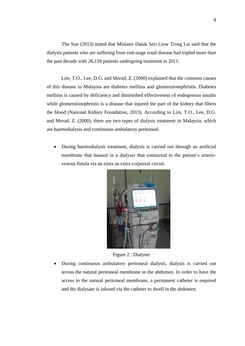
During haemodialysis treatment, dialysis is carried out through an artificial
membrane that housed in a dialyser that connected to the patient’s arterio-
venous fistula via an extra an extra corporeal circuit.
Figure 2 : Dialyser
During continuous ambulatory peritoneal dialysis, dialysis is carried out
across the natural peritoneal membrane in the abdomen. In order to have the
access to the natural peritoneal membrane, a permanent catheter is required
and the dialysate is infused via the catheter to dwell in the abdomen.

10
Figure 3 : Continuous ambulatory peritoneal dialysis
(Source : Baxter, 2013)
2.3 Guidelines for the healthcare institution providing renal dialysis
Many precaution steps have been taken by the dialysis centres. This is because of
there are many contacts with the blood of the patient and the dialyser machines are
shared among the dialysis patients.
According to Ministry of Health Malaysia (2012), the patients who are having
Hepatitis B, Hepatitis C or Human Immuno-deficiency Virus required prevention and
isolation practice. The patients are required to test for Hepatitis B, Hepatitis C or
Human Immuno-deficiency Virus before they are initiating the first haemodialysis
treatment or after returning from another haemodialysis facility. All the Hepatitis B,
Hepatitis C or Human Immuno-deficiency Virus patients required to be isolated in a
separate room and they should be dialyzed using separate machines, equipment and
instruments. For the patients who are at the risk of acquiring viral infection, they are
strongly recommended to dialyse with single use dialyser or the dialyser machine is
dedicated for an unknown viral status until the particular patient is out of the window
period for the respective infection. Dialysis patients are recommended to have their
blood test for monthly intervals.

11
2.4 Dialysis Data Management
According to the Malaysian Society Nephrology (2011), National Renal Registry
collects all the information of the kidney failure patients and all these data are
required to estimate the treatment rates in the country as well as to assist the Ministry
of Health, Non- Governmental Organization, private providers and industry in the
planning and evaluation of the renal replacement therapy. The National Renal
Registry requires the cooperation from the different sector that provides the dialysis
services and renal replacement therapy in order to obtain the latest information of all
the renal replacement therapy and dialysis in Malaysia.
Every dialysis centres are having their own method of gathering and
managing their patients’ information. Some dialysis centres are recording their
patients’ data in paper-based while some of the dialysis centres are having their own
system to manage their patients’ data and information. The examples for the systems
that help to manage the dialysis patients’ information are shown as below.
i. Therapy Data Management System
Figure 4 : Therapy Data Management System
( Source : Fresenius Medical Care, 2012)
According to Fresenius Medical Care (2012), Therapy Data Management
System is developed by Fresenius Medical Care. This system helps in
recording the weight of a patient before and after dialysis and preparing
and pre-setting of the dialysis device. Besides that, this system also helps
in documenting the treatment process, any addition al laboratory tests
during the dialysis and any changes in the treatment procedures.

12
ii. Finesse Professional
Figure 5 : Finesse Professional
( Source : Fresenius Medical Care, 2012)
Based on Fresenius Medical Care (2012), this Finesse Professional system
helps to simplify routine works, improve treatment quality and ease technical
operation of procedures. It helps the dialysis centres in planning and
organizing the daily routine works. This system collects patients’ data
through the entry of the nursing staff. This system has been developed in
close operation which means that it is used by the staff and the users in the
dialysis centre only.
All these systems are used to manage the patients’ information and their visit
records. Besides that, these systems are linked to dialysis machines and other
important medical devices. All these data that collected are mainly for the internal
use of the dialysis centres.
2.5 Centralised Data
For the current situation, every dialysis centres are holding their own patients’
information and visiting records. The patients themselves do not have the visiting
records and their medical information is all in paper-based manner. When they need
to go for another dialysis centre for haemolysis treatment, the dialysis centre requires
their information and the latest blood test result due to the precaution steps that
provided by the Ministry of Health Malaysia in order to protect the patients from the
infection of the Hepatitis B, Hepatitis C or Human Immuno-deficiency Virus (HIV).
Hence, they require the patient’s dialysis centre to fax or mail their medical

13
information to the particular dialysis centre that the patient wanted to visit and this is
time consuming.
Heeks, R. (1999) explained that through the centralization of the data, it helps
in sharing resources. A well-planned centralised system holds data used across the
community or across the organization allowing all the people involved to access it.
This helps to improve the efficiency and effectiveness of the dialysis centres. Other
than that, it also avoids duplication of the data and records. It helps to maintain single
version of any particular information system for the whole community or the
organization and to store data once and only once. Hence, there is no waste of effort,
storage capacity and inconsistency of data.
By the centralization of the data of the patients, the patients are able to get
their latest information easily wherever they go. Besides that, it also helps to avoid
any not updated information or inconsistent medical information of the patient as the
latest medical information of the dialysis patients are important for every dialysis
centres.
2.6 Related Work
Due to the population of the dialysis patients in Malaysia is small and less attention
is given to these patients, hence, there is no dialysis centre or research on gathering
the dialysis patients’ data in order to ease the patients in Malaysia. However, some
systems that gather and manage the data are available in the market. This section will
describe on the available systems and their functions.

14
2.6.1 Gambro Dialysis Data Management Tool
Figure 6 : Gambro Dialysis Data Management Tool
( Source : Gambro, 2011)
This system helps the dialysis centres to manage their dialysis facilities and improve
their overall performance. Gambro Dialysis Data Management Tool will
automatically collect the treatment data of the patient and it also allows real time
access to treatment data and real time report of alarms and events.
Other than that, Gambro Dialysis Data Management Tool will automatically
help the dialysis centres to do preparation and print out treatment forms and
treatment run-sheets. This system also helps to optimise the patient care before,
during and after the treatment.
Before the treatment, it provides the centres an intelligent tool to help the
nurse to define the optimal dose for the dialysis patient. During the treatment, the
system will provide pre-dialysis measurement for example, patient weight and blood
pressure. Besides, it also helps to monitor patient’s condition continuously and
records the every single event. At the end of the treatment, treatment analysis will be
conducted by the system to calculate the exact dose to be delivered to the patient.
This system can be conducted via online, offline or remote. If the system is
used offline, the data is transmitted via patient card. If the system is online, the data
can be transmitted via local area network. If the system is remote, the data can be
transmitted over the phone or internet (Gambro, 2011).
15
2.6.2 GJI iCentral
Figure 7 : GJI Pty Ltd
(Source : GJI Pty Ltd, 2013)
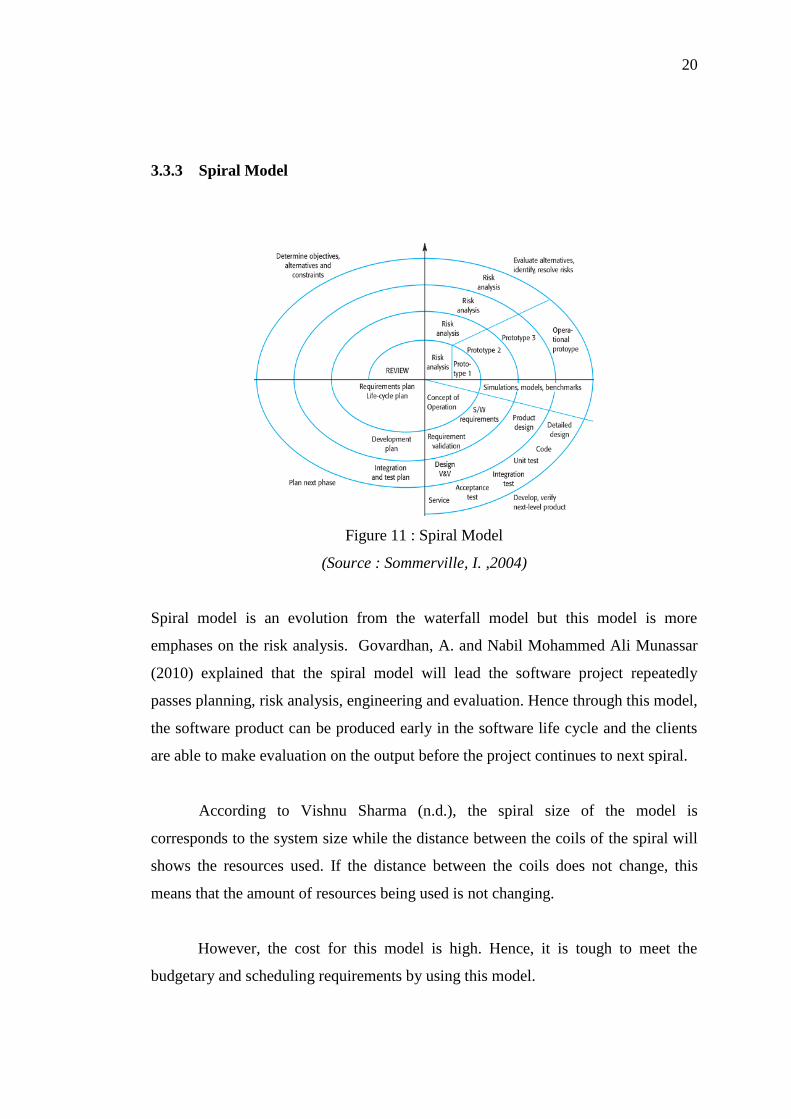
GJI Pty Ltd provides data centralisation systems to the customers called iCentral.
This system is able to consolidate multiple data sources into a centralised system that
is easy to manage and provides customer with a customized dashboard to allow them
to access their data easily.
Figure 8 : Data centralised system by GJI Pty Ltd
(Source : GJI Pty Ltd, 2011)

16
CHAPTER 3
METHODOLOGY
3.1 Project Description
This project is designed to solve the problem that stated in the problem statement.
The objective of the project is to ease the dialysis patients, dialysis centres and
doctors to get the patient information and data.
This project contains 2 modules. The first module is where the dialysis
patients view their information and track their records. Besides, the dialysis patients
also can send their information to the doctor or dialysis centres through this section.
The system does not allow the patients to change any of their information, they only
have the right to send and view their information. In the module 2, the dialysis
centres are able to view and update the patient’s visiting records. The system gives
the dialysis centres the authority to insert new records to the patient’s visiting records
but not editing the previous data. Besides that, the dialysis centres are also having the
rights to enter the patient blood test result. Some patients who are having Hepatitis B,
Hepatitis C or Human Immuno-deficiency Virus (HIV), they are required to have
blood test for every 3 months according to Ministry of Health Malaysia (2012).
Hence the system will send the notification to the patients, dialysis centres as well as
the blood test centres.
All their data will be stored in the server where this server could be managed
by The Malaysian Red Crescent Society, one of the NGO. By using this system, all

17
the health information and data are all on the hand of the patient and this information
can be retrieved just with one click. Besides that, the system is designed to be simple
and easy to use in order to suit for every user.
3.2 System Architect
User Interface
- Patient
- Dialysis Centres
Patient data and
information database
Figure 9 : Centralised data for dialysis patient system architect

18
3.3 Software Development Life Cycle
3.3.1 Introduction
There are varieties of development approaches designed to be used or deployed for
the development process of software. The purpose for every model is to ensure
success in the process of software development. Rouse, M. (2009) explained that the
software development life cycle is a conceptual model that being used in project
management that describes all the stages involved in the information system
development project from the initial feasibility study through maintenance of the
completed system. There are various software development life cycle methodologies
have been developed for instance, waterfall model, rapid application development,
spiral model and agile method.
3.3.2 Waterfall Model
Specification
Requirements
Design
Implementation
Maintenance
Test
Figure 10 : Waterfall Model

19
According to Vishnu Sharma (n.d.), waterfall model is popular in 1970s. The
waterfall model is fall from top to the bottom which shows the development process
from the top to the bottom in steps. It emphasizes on completing a phase before
proceeding to the next phase. This type of model is suitable for system which does
not require frequently change on the requirement specification. The minor changes
can be done through a maintenance process or through the small design changes.
Disadvantages of Waterfall Model are every phase is isolated from the other
stage in the waterfall model and every phase is needed to be completed before move
on to the next stage. According to Sommerville, I. (2004), waterfall model does not
cope well with changes, generating rework and may cause unpredictable software
qualities due to delay testing. To develop a system, the clients often not clear on their
own requirements. Hence the requirement specification is always changing. Any
changes made by the clients may cause confusion. Besides, the customers are unable
to review the final product until the last stage of the waterfall model. This might
causes the final products do not fulfil the requirement of the customers.
20
3.3.3 Spiral Model
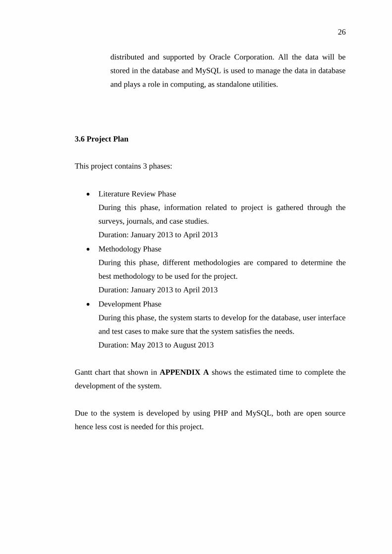
Figure 11 : Spiral Model
(Source : Sommerville, I. ,2004)
Spiral model is an evolution from the waterfall model but this model is more
emphases on the risk analysis. Govardhan, A. and Nabil Mohammed Ali Munassar
(2010) explained that the spiral model will lead the software project repeatedly
passes planning, risk analysis, engineering and evaluation. Hence through this model,
the software product can be produced early in the software life cycle and the clients
are able to make evaluation on the output before the project continues to next spiral.
According to Vishnu Sharma (n.d.), the spiral size of the model is
corresponds to the system size while the distance between the coils of the spiral will
shows the resources used. If the distance between the coils does not change, this
means that the amount of resources being used is not changing.
However, the cost for this model is high. Hence, it is tough to meet the
budgetary and scheduling requirements by using this model.

21
3.3.4 Agile Model
Figure 12 : Agile Model
(Source : Hughes Systique, n.d.)
Sheetal Sharma, Darothi Sarkar and Divya Gupta (2012) explained that agile model
is an iterative and incremental based model. In this model, the requirements are
changeable based on the client needs. Hence, it helps in adaptive planning, iterative
development and time boxing. In the agile process, it requires the client to have
direct involvement in evaluating the software to increase the satisfaction by the client.
Agile process has a high ability to adapt the changing environment, this is because
there are several iterations in the model and each iteration is characterized by
analysis, design, and implementation and testing. After each iteration, it will be
tested and getting feedback from the clients. This will help to decrease the risk of the
development as the incremented mini software is delivered to the clients and
feedback is taken from the clients.
Sheetal Sharma, Darothi Sarkar and Divya Gupta (2012) also explained that
this agile model requires high involvement of the client and the entire project is
developed based on the client requirements. If the client is not clear on the software
features, this might cause the project to be delayed or out of track.

22
3.3.5 Rapid Application Development (RAD)
Figure 13 : Rapid Application Development (RAD)
(Source : Vikash, 2012)
According to Martin, J. (1991), rapid application development is a model that
designed to provide a faster development but with higher quality result if compare to
those traditional life cycles. This model is designed to take maximum advantage of
powerful development software that has evolved at that time.
NC DENR System Development Life Cycle Methodology (1999) wrote that
Rapid application development model integrated project management techniques,
development techniques, users and tools to build quality application system. Rapid
development combines focused teams working in a high structured environment.
This model enables fast delivery. Rapid application development increased
development speed and decreased time to delivery. This model has some tools which
help to focus on converting requirements to code as fast as possible, it enables the
developers to re-use previously generated code. Besides that, the quality can also be
assured by using this model. The quality of the system can be enhanced by meeting
the requirement of the clients. On the other hand, this model reduces scalability and
features. Due to the time boxing, some features are pushed off to later versions in

23
order to deliver the system in a short time frame. Besides, this model is mainly
focuses on development of a prototype that is iteratively developed into a full system.
Hence, the delivered solution may lack of scalability of a solution according to Core
Partners Inc (n.d.).
3.4 Method Selected
Based on the researches and comparison among the model that available, the most
suitable software development methodology model to be used to develop this project
is Rapid Application Development (RAD).
Rapid Application Development (RAD) is selected because of:-
- Development time is shorter
The timeframe given by university to develop final project system is less
than 4 months. Besides that, RAD model encourage to develop the main
core of the system before adding addition features to the system in order
to decrease the development time. This is suitable for the current system
where the centralise the patient is the main core of the system while the
security or the dialysis centres locator feature will be added after the
completion of the main core of the system.
- Flexible and adaptive to change
RAD model increase the flexibility of the system. During the
development, the clients always change their requirements. Hence, by
using RAD model, it will not affect the entire project.
In this project, the features can be added into the system during the
development easily if the time is allowed. Besides that, RAD also
provides an updated “look and feel” of the evolving product to make sure
that the system is always on the right track.

24
- Better project management
The main purpose of project management is to ensure a quality system
can be done in time and within the budget given. Since the time frame for
this project is short therefore the project management is very important.
RAD is suitable for this project. RAD model is having active
participation of the stockholders. Hence, less error or misunderstanding
of the requirements will happen, which may lead to prolong the
development time.
During the analysis phase of RAD, the objective, target audience, mode of
delivery and the target audience requirements are need to be gathered. All the
information that are required for the development of the Dialysis Data Management
System is collected from the dialysis centers as well as the dialysis patients. The
database is first designed based on the information gathered. Besides that, a constant
update of the system with the dialysis centres is required to ensure that the system is
on track and is developed based on their requirement. Other than that, related
projects and related documents are studied in order to get more information about the
system which is going to be developed and to ensure that there is no duplication of
similar system exists.
The next phase of the RAD is prototype cycle which is the design phase. In
this phase, it consists of builds, demonstrate and refine. During this phase, the
progress of the system is constantly updated and demonstrated to the users. This is to
ensure that the system is always on track and within the scope of the users. If there is
any correction or out of the users’ scope, the system can be rectified easily and be
corrected in shorter time. On the other hand, if the system is found not fulfilling the
user requirements after the system is done, it will take more time to correct the
system. Hence, build and demonstrate at same time is more time saving and more
secure when the project has to be developed within a limited time.
Next will be the testing. Unit testing, integration testing, functional testing
and acceptance testing are being done during this phase. This is to ensure that the
system is work correctly and the data is passing correctly between the interfaces as

25
well as the database. Besides that, the acceptance test which is done by the users is
tested after the system is completely done. This acceptance test is to prove that the
system is done based on their requirement and test on their satisfaction on the system.
Lastly will be the implementation. During this phase, the system is delivered
to the users and evaluation will be taken. This Dialysis Data Management System
will be implemented in the actual environment. Some of the actual patient data is
keyed into the system. This system required a web based as well as database is
required. Hence, the system is required to be deployed into the World Wide Web by
using the hosting services.
3.5 Development Tool
1. PHP
PHP is known as hypertext pre-processor. This PHP is widely used for
web development and it can be embedded into HTML. The code of PHP
is executed in the server and it generates html then send to the client. This
enables the client to view the result but do not know what the underlying
code was. Besides that, PHP is working well with MySQL as well as
cloud services. PHP also offers a lot of the security mechanisms to avoid
from the PHP file in the server being changed. One of the technologies is
Encoding PHP files where the editable plain text files is changed to
binary format.
2. MySQL
MySQL is a relational database management system that uses Structured
Query Language. It is used to adding, accessing and managing (add,
access and manage) content in a database. MySQL is developed,
26
distributed and supported by Oracle Corporation. All the data will be
stored in the database and MySQL is used to manage the data in database
and plays a role in computing, as standalone utilities.
3.6 Project Plan
This project contains 3 phases:
Literature Review Phase
During this phase, information related to project is gathered through the
surveys, journals, and case studies.
Duration: January 2013 to April 2013
Methodology Phase
During this phase, different methodologies are compared to determine the
best methodology to be used for the project.
Duration: January 2013 to April 2013
Development Phase
During this phase, the system starts to develop for the database, user interface
and test cases to make sure that the system satisfies the needs.
Duration: May 2013 to August 2013
Gantt chart that shown in APPENDIX A shows the estimated time to complete the
development of the system.
Due to the system is developed by using PHP and MySQL, both are open source
hence less cost is needed for this project.
27
CHAPTER 4
DESIGN
4.1 Introduction
In the design phase, a systematic process of designing the front-end and the back-end
of the system are determined and planned. During this stage, the storyboards, user
interface and the databases are designed. Besides that, the architecture design and
system flow chart are also illustrated. Below are the components that will be
considered during this phase:
- Use case
- Flow Chart
- System architecture Design
- Story board design
- Database design
4.2 Use Case
According to Rouse, M. (2007), use case is a methodology used in system analysis to
identify, clarify, and organize system requirements. The use case is made of a set of
possible sequences of interaction between the users and the systems in the Dialysis

28
Data Management System environment. Diagrams below show the use case for the
dialysis centres as well as for the patients.
Figure 14 : Dialysis Centre's Use Case Diagram
Figure 15 : Dialysis Patient's Use Case Diagram

29
4.3 Flow Chart
Edraw, a professional diagram solution company (2004) explained that a flow chart
is visually presenting the flow of data through an information process system..
Diagrams below show the flow chart for the dialysis centers and the dialysis patients.
Figure 16 : Dialysis Centre's Flow Chart

30
Figure 17 : Dialysis Patient's Flow Chart

31
4.4 System Architecture Design
Figure 18 : Dialysis Data Management System Architecture Design
Dialysis Data Management website will be installed in the Dialysis Centre’s web
server. A client of the website can be the dialysis centre or the dialysis patient that
has an internet connection. The client will access the web server through the firewall.
The request will sent to the firewall and the firewall will get the access to the web
server where the system will be stored. The Dialysis Data Management Website will
be connected to the database where all the information that is needed will be added
and stored.
In conclusion, when the clients send request to the firewall, the firewall will
contacts the firewall where the website is stored and access to all information which
stored in the database.
4.5 Storyboard Design
Storyboard is an illustration of the entire scenario from the beginning to end
including every screen that the user will go through. The storyboard samples for this
project are shown as below:

32
Figure 19 : Storyboard of DDMS Login Page
Figure 20 : Storyboard of DDMS dialysis centre’s main page
Graphical Instruction
Text (T)
Description
T1 : Booking
T2 : Updates
T3: Help
T4: Logout
T5 : Search patient / Add new patient
Click on T1 to go to booking screen. To
view for patients’ booking.
Click on T2 to go to updates screen. To
update dialysis information and
password.
Click on T3 to go to help screen. To get
tutorial on how the website work.
Click on T4 to go Logout from the user.
Search on particular patient or add new
patients.
Table 2 : Description of dialysis centre's main page in detail.

33
Figure 21 : Storyboard of DDMS dialysis centre's view of patient detail
Graphical Instruction
Text (T)
Description
Search
T2 : Patient Detail
T3: Medical Record
T4: Dialysis Record
Menu
Search for another patient.
Click on T2 to view more detail of the
patient information.
Click on T3 to view the patient’s medical
record.
Click on T4 to view the patient’s dialysis
record.
Side menu to access for patient’s detail,
medical record and dialysis record.
Table 3 : Description of dialysis centre patient’s detail page in detail.
34
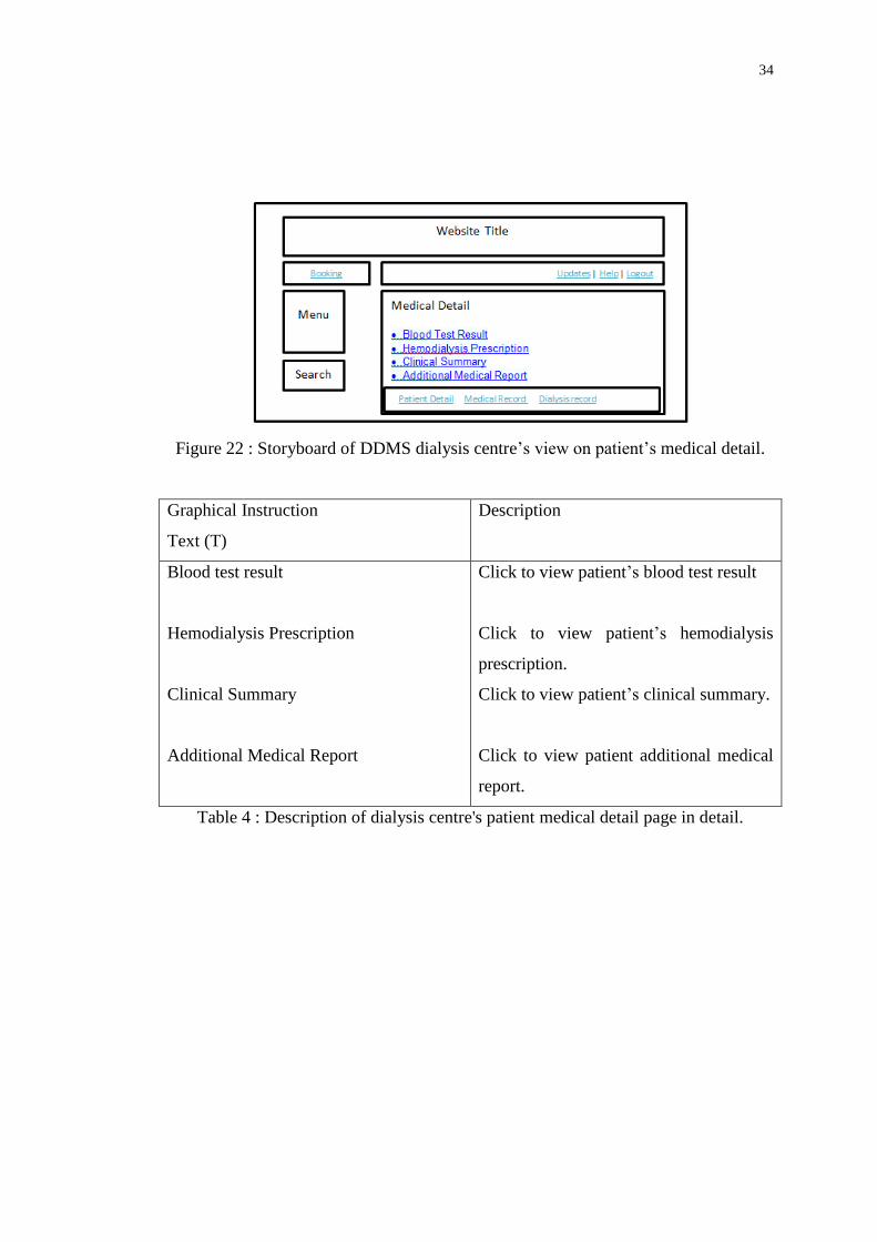
Figure 22 : Storyboard of DDMS dialysis centre’s view on patient’s medical detail.
Graphical Instruction
Text (T)
Description
Blood test result
Hemodialysis Prescription
Clinical Summary
Additional Medical Report
Click to view patient’s blood test result
Click to view patient’s hemodialysis
prescription.
Click to view patient’s clinical summary.
Click to view patient additional medical
report.
Table 4 : Description of dialysis centre's patient medical detail page in detail.

35
Figure 23 : Storyboard of DDMS dialysis centre’s view on patient blood test report.
Graphical Instruction
Text (T)
Description
T1 :Blood test date
T2 : Add new record
Display the date of the report according
and click on for the report detail.
Add new blood test report.
Table 5 : Description of dialysis centre's patient blood test report page in detail.
Figure 24 : Storyboard of DDMS dialysis centre’s view on patient blood test report
detail.

36
Figure 25 : Storyboard of DDMS dialysis centre’s view on add new patient blood test
report form.
Figure 26 : Storyboard of DDMS dialysis centre’s view on patient haemodialysis
prescription.
Figure 27 : Storyboard of DDMS dialysis centre’s view on patient clinical summary.

37
Figure 28 : Storyboard of DDMS dialysis centre’s view on patient additional medical
report.
Graphical Instruction
Text (T)
Description
T1 :Additional medical report
T2 : Add new record
Display the date of the report according
and click on for the report detail.
Add new medical report.
Table 6 : Description of dialysis centre's patient additional medical report page in
detail.
Figure 29 : Storyboard of DDMS dialysis centre’s view on adding new patient
medical report form.

38
Figure 30 : Storyboard of DDMS dialysis centre’s view on patient visitation record.
Graphical Instruction
Text (T)
Description
T1 :Visitation record
T2 : Add new record
Display the date of the report according
and click on for the report detail.
Add new visitation record.
Table 7 : Description of dialysis centre's patient visitation record page in detail.

39
Figure 31 : Storyboard of DDMS dialysis centre’s view on patient clinical summary.
Graphical Instruction
Text (T)
Description
T1 :Click for detail
T2 : Click for print report
Click T1 to view for the patient’s dialysis
record detail.
Click T2 to print the record.
Table 8 : Description of dialysis centre's patient clinical summary in detail.
Figure 32 : Storyboard of DDMS dialysis centre’s view on adding new patient
dialysis record.

40
Figure 33 : Storyboard of DDMS patient’s main page.
Graphical Instruction
Text (T)
Description
T1 :Personal information
T2 : Medical record
T3 :Dialysis record
T4 :Booking
Click T1 to view for the patient’s
personal information.
Click T2 to view for the patient’s
medical record.
Click T3 to view for the patient’s dialysis
record
Click T4 for booking and view booking
status.
Table 9 : Description of dialysis centre's patient main page.
41
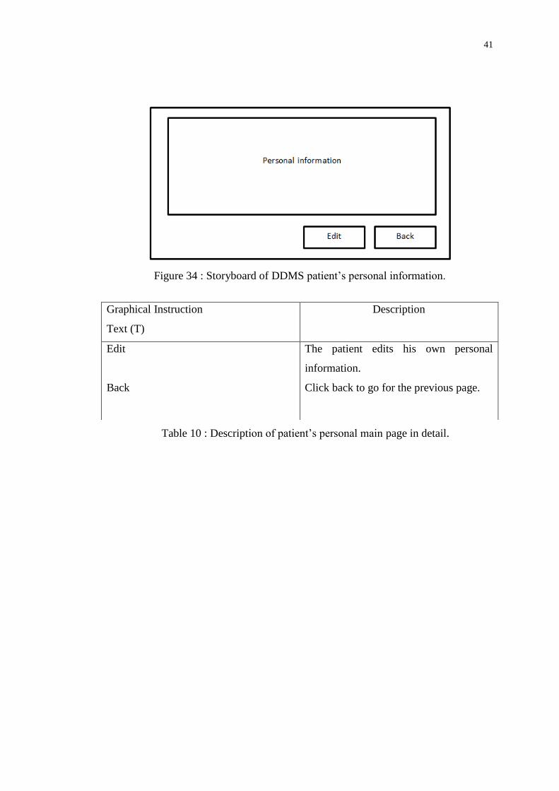
Figure 34 : Storyboard of DDMS patient’s personal information.
Graphical Instruction
Text (T)
Description
Edit
Back
The patient edits his own personal
information.
Click back to go for the previous page.
Table 10 : Description of patient’s personal main page in detail.

42
Figure 35 : Storyboard of DDMS patient’s medical record page.
Graphical Instruction
Text (T)
Description
Blood test result
Hemodialysis Prescription
Clinical Summary
Additional Medical Report
Click to view patient’s blood test result
Click to view patient’s hemodialysis
prescription.
Click to view patient’s clinical summary.
Click to view patient’s additional
medical report.
Table 11 : Description of patient’s medical record page in detail.

43
Figure 36 : Storyboard of DDMS patient’s partial visitation record page.
Graphical Instruction
Text (T)
Description
Click for detail
Click to view for the patient’s dialysis
visitation record detail.
Table 12 : Description of patient’s partial visitation record page in detail.
Figure 37 : Storyboard of DDMS patient’s visitation record page.
Graphical Instruction
Text (T)
Description
Visitation record
Display the date of the report according
and click on for the report detail.
Table 13 : Description of patient’s visitation record page in detail.

44
Figure 38 : Storyboard of DDMS patient’s booking page.
Graphical Instruction
Text (T)
Description
Submit
View booking
Click to submit the booking
Click to view the status of booking
Table 14 : Description of patient’s booking page in detail.
4.6 Database Design
4.6.1 Introduction
According to Connolly, T. and Begg, C. (2010), database design is one of the stages
on system development life cycle. In the database design, it consists of conceptual
database design and logical database design. Conceptual database design is to build a
conceptual representation of the database, which includes identification of the
important entities, relationships and attributes. This part will describe on the
conceptual design.
45
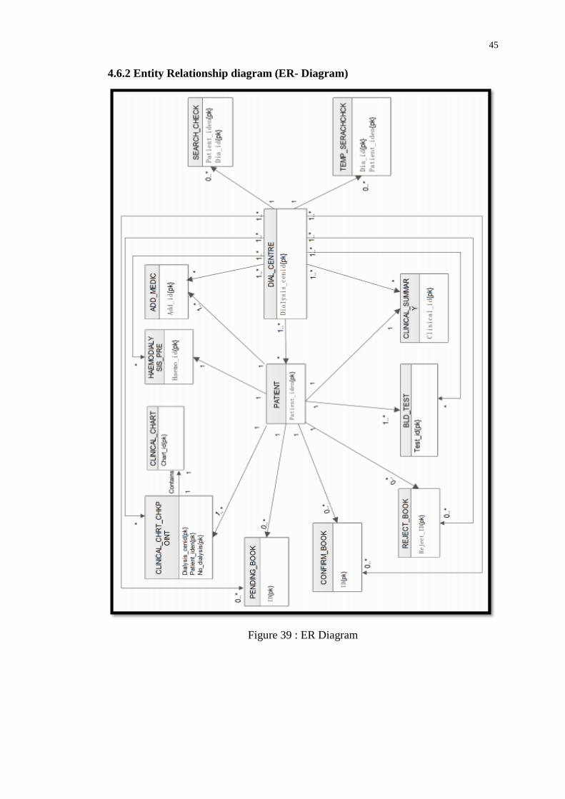
4.6.2 Entity Relationship diagram (ER- Diagram)
Figure 39 : ER Diagram
46
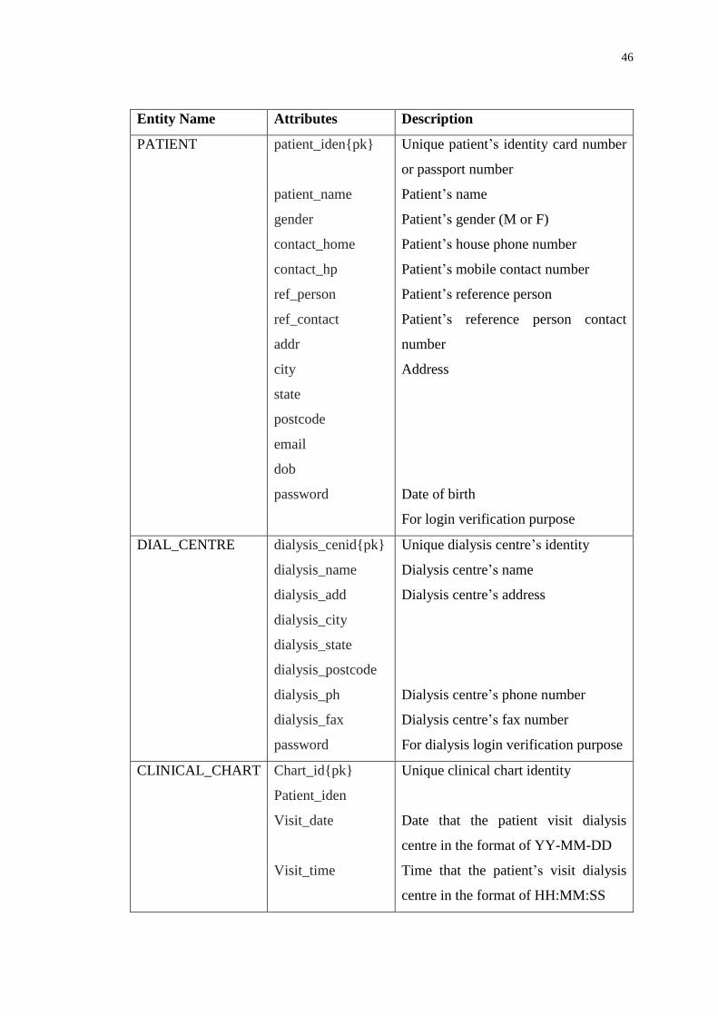
Entity Name Attributes Description
PATIENT patient_iden{pk}
patient_name
gender
contact_home
contact_hp
ref_person
ref_contact
addr
city
state
postcode
dob
password
Unique patient’s identity card number
or passport number
Patient’s name
Patient’s gender (M or F)
Patient’s house phone number
Patient’s mobile contact number
Patient’s reference person
Patient’s reference person contact
number
Address
Date of birth
For login verification purpose
DIAL_CENTRE dialysis_cenid{pk}
dialysis_name
dialysis_add
dialysis_city
dialysis_state
dialysis_postcode
dialysis_ph
dialysis_fax
password
Unique dialysis centre’s identity
Dialysis centre’s name
Dialysis centre’s address
Dialysis centre’s phone number
Dialysis centre’s fax number
For dialysis login verification purpose
CLINICAL_CHART Chart_id{pk}
Patient_iden
Visit_date
Visit_time
Unique clinical chart identity
Date that the patient visit dialysis
centre in the format of YY-MM-DD
Time that the patient’s visit dialysis
centre in the format of HH:MM:SS
47
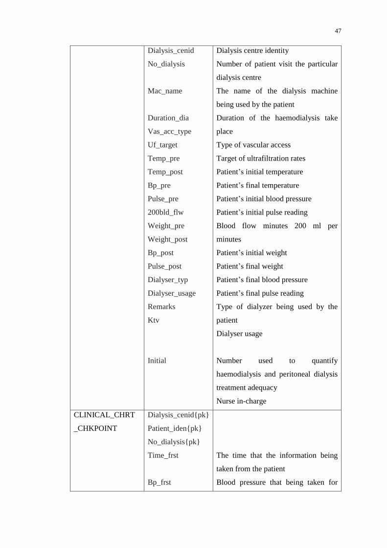
Dialysis_cenid
No_dialysis
Mac_name
Duration_dia
Vas_acc_type
Uf_target
Temp_pre
Temp_post
Bp_pre
Pulse_pre
200bld_flw
Weight_pre
Weight_post
Bp_post
Pulse_post
Dialyser_typ
Dialyser_usage
Remarks
Ktv
Initial
Dialysis centre identity
Number of patient visit the particular
dialysis centre
The name of the dialysis machine
being used by the patient
Duration of the haemodialysis take
place
Type of vascular access
Target of ultrafiltration rates
Patient’s initial temperature
Patient’s final temperature
Patient’s initial blood pressure
Patient’s initial pulse reading
Blood flow minutes 200 ml per
minutes
Patient’s initial weight
Patient’s final weight
Patient’s final blood pressure
Patient’s final pulse reading
Type of dialyzer being used by the
patient
Dialyser usage
Number used to quantify
haemodialysis and peritoneal dialysis
treatment adequacy
Nurse in-charge
CLINICAL_CHRT
_CHKPOINT
Dialysis_cenid{pk}
Patient_iden{pk}
No_dialysis{pk}
Time_frst
Bp_frst
The time that the information being
taken from the patient
Blood pressure that being taken for
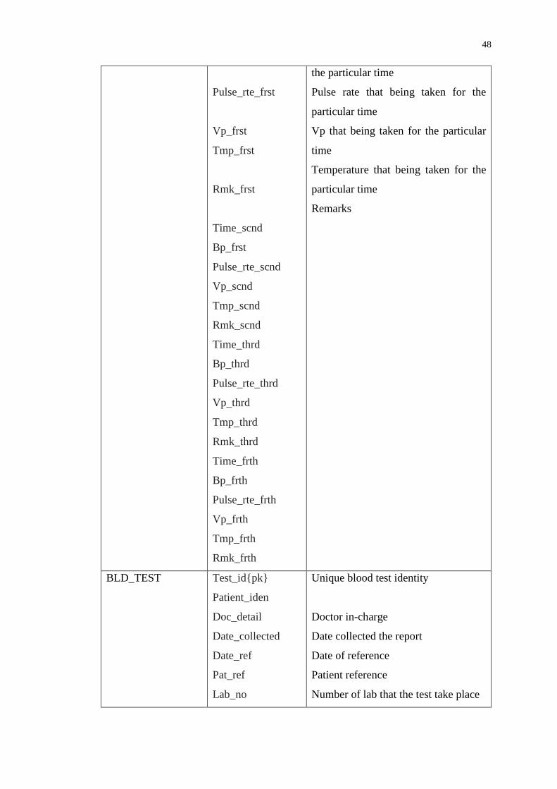
48
Pulse_rte_frst
Vp_frst
Tmp_frst
Rmk_frst
Time_scnd
Bp_frst
Pulse_rte_scnd
Vp_scnd
Tmp_scnd
Rmk_scnd
Time_thrd
Bp_thrd
Pulse_rte_thrd
Vp_thrd
Tmp_thrd
Rmk_thrd
Time_frth
Bp_frth
Pulse_rte_frth
Vp_frth
Tmp_frth
Rmk_frth
the particular time
Pulse rate that being taken for the
particular time
Vp that being taken for the particular
time
Temperature that being taken for the
particular time
Remarks
BLD_TEST Test_id{pk}
Patient_iden
Doc_detail
Date_collected
Date_ref
Pat_ref
Lab_no
Unique blood test identity
Doctor in-charge
Date collected the report
Date of reference
Patient reference
Number of lab that the test take place

49
Test_req
Hiv_state
Hiv_det
Serology_state
Serology_det
Hep_state
Hepb_antigen
Hepb_antibdy
Hepc_antibdy
Hep_det
Test that being requested by the
patient
The HIV status of the patient
The HIV detail of the patient
The serology status of the patient
The serology detail of the patient
The hepatitis status of the patient
The status of hepatitis b antigen by
the patient
The status of the hepatitis b antibody
by the patient
The status of the hepatitis c antibody
by the patient
The hepatitis detail of the patient
CLINICAL_
SUMMARY
Clinical_id{pk}
Patient_iden
Doc_inchar
Clinical_name
Clinical_add
Rep_date
Med_pro
Rpt_his
Diaacc_his
Pres
Clinical_note
Plan_no
Bill_no
Unique clinical summary identity
Medical problem
Renal replace therapy history
Dialysis access history
Prescription
Clinical notes
HAEMODIALYSIS
_PRE
Haemo_id{pk}
Patient_iden
Dry_weight
Idwg_frm
Unique haemodialysis prescription
identity
Inter-dialytic weight gain (from)

50
Idwg_to
Avr_prebp
Avr_pstbp
Freq
Duration
Arterial_ndl
Venous_ndl
Bolus_hepdos
Cont_hepdos
Con_a
Con_b
Bldflw_frm
Bldflw_to
Dialysate_flw
Venpres_frm
Venpres_to
Drug_allrgy
Inter-dialytic weight gain (to)
average of the initial blood pressure of
the patient
average of the final blood pressure of
the patient
frequency(times per week)
The arterial needle that being used by
the patient
the venous needle that being used by
the patient
Bolus heparin dosage
Continuous heparin dosage
Concentrate a that being used by the
patient (e.g. Low calcium)
Concentrate b that being used by the
patient (e.g. Bicarbonate)
Blood flow rate (from)
Blood flow rate (to)
Dialysate flow
Venous Pressure(from)
Venous Pressure (to)
Drug allergy
ADD_MEDIC Add_id{pk}
Patient_iden
Doc_inchar
Clinic_name
Clinica_add
Rep_date
Patient_ref
Lab_no
Report_title
Rep_detail
Unique additional medic identity
Report title
Report detail

51
SEARCH_CHECK Patient_iden{pk}
Dia_id{pk}
Check
Check if the dialysis centre is been
checked
TEMP_
SEARCHCHCK
Dia_id{pk}
Patient_iden{pk}
Confirm_code
Code that send to the patient through
email for verification purpose
PENDING_BOOK ID{pk}
Patient_iden
Diacen_id
Date
Reason
Unique pending book identity
CONFIRM_BOOK ID{pk}
Patient_iden
Diacen_id
Date
Time_frm
Time_to
Duration
Remark
Unique confirm book identity
REJECT_BOOK Reject_ID{pk}
Patient_iden
Diacen_id
Date
Reason
Unique reject book identity
Table 15 : Data dictionary of DIALYSISCEN, showing a description of attributes.
52
CHAPTER 5
IMPLEMENTATION
5.1 Introduction
According to IEEE Standard Glossary of Software Engineering Terminology (1990),
implementation is the process of translating a design into hardware components,
software components or both. Implementation also concerns about the result of the
process of translation the design.
This chapter will discuss about the implementation of the system where the
technology and tools that are used for the implementation. Besides that, this chapter
will also discuss on the implementation flow and decisions and the development
process of the project in detail.
5.2 Technology Comparison
There are many technologies that can be used to develop this Dialysis Data
Management system. Every technology has different advantages and disadvantages.
During this section, different technology is compared and discussed and further
explanat ion on thei r funct ional i t y, advantages and d isadvantages .
53
5.2.1 Active Server Pages (ASP)
Figure 40 : Active Server Pages
(Source: ASP.NET, 2013)
Microsoft Developer Network (n.d) explains that active server pages is a server-side
scripting environment that the developer can use to create and run dynamic,
interactive Web server application. It can combine HTML pages, script commands
and COM components in order to create interactive web pages and web-based
application.
Below are the advantages of the ASP:
- ASP is maintained by Microsoft. The technology is constantly updated.
Hence, it is more reliable and has higher levels of security.
- According to Debray, T. (2012), ASP use less execution time. This is because
ASP is compiled hence it does not need to set up the connection and query
the databases that cause most of the page rendering time arises.
- Microsoft provides IDE to facilitate the development of the active server
pages. Hence, it eases the development of ASP as well as reduces the time of
development.
Below are the disadvantages of the ASP:
- ASP has limited control on HTML. ASP uses server to control render
themselves as HTML. The problem is that ASP causes the HTML output
difficult to comply with the web standard. Besides that, it also causes the
JavaScript difficult to be accessed due to complex ID values generated by the
server.

54
- ASP will cause frustration to the users due to it requires times and increase
the bandwidth demands of the server for the first time users.
5.2.2 Java Server Pages (JSP)
Figure 41 : Java Server Pages
(Source: Java, 2013)
According to Chien-Hung Liu (2004), Java Server Pages is another technology that is
used to handle the server-side scripts which used to manage the HTTP request, to
generate dynamic contents as well as used to interact with other components. Java
Server Pages is a server side script which use Java technology.
Below are the advantages of the JSP:
- Java Server Pages support reusable components. The dynamic part of the
Java Server Pages is written in Java hence it is suitable for the complex
application that requires reusable components.
- Java Server Pages is free and open source. Hence less costing is required.
Below are the disadvantages of the JSP:
- JSP pages require more disk place to store the page. This is because of the
JSP pages are needed to be translated into class files and the server is
required to store the resultant class files with the JSP pages. Hence, JSP need
more disk place to store the page.

55
- Same as ASP. JSP page is compiled. It required to be compiled on the server
during the user first accessed. Hence, it requires times and increases the
bandwidth demands of the server for the first time users.
5.2.3 Hypertext Preprocessor (PHP)
Figure 42 : Hypertext Pre-processor
(Source: PHP, 2013)
Php.net (n.d.) explained that PHP is a widely used general purpose scripting
language that is suitable for the web development and can be embedded into HTML
and the PHP scripts can be executed on the server.
Below are the advantages of the PHP:
- PHP is compatible with most of the operating systems and web servers. This
enables it to deploy across different platforms easily.
- PHP provides a lot of libraries and extensions besides its core functionalities.
- PHP supports structural programming and object oriented programming. It is
simple and easy to learn.
- PHP has good connective abilities. PHP has a modular system of extensions
to interface with number of libraries. Besides that, it also able to extend PHP
by writing a new extensions or write own executable and load it using PHP’s
dynamic loading mechanism.

56
Below are the disadvantages of the PHP:
- PHP is not very modular. Hence it is not suitable for a large application.
- Source code can be easily viewed. This is because the PHP codes are not
compiled and can be accessed easily as a plain text files. This causes some
security issues.
5.2.4 Technology Selected
The technology that has been selected for the Dialysis Data Management System is
PHP. This main purpose of the system is the usability. Hence, the system needs to be
simple, easy, fast and efficient to be used. ASP and JSP also required to be compiled
on the server during the user first accessed and it takes times and increases the
bandwidth demands of the server for the first time users. Besides that, JSP took more
disk place to store the page compared to other technology. In addition, Dialysis Data
Management System manages many patient’s data and this will cause more disk
place is required if JSP technology is used.
PHP is not considered the perfect technology to be used but it is the most
suitable for the Dialysis Data Management System. This is because PHP is suitable
and easier to manage the SQL database. It does not need to take so many times or
disk places like what JSP and ASP required. In addition, PHP and MySQL are open
source and there are many community and developers involved. Many additional
functions are available and facilitate most tasks.

57
5.3 Development Tools and Technologies
This section will discuss on the technologies and the tools that are required to
develop the Dialysis Data Management System. The technologies and tools that will
be used for the system are:
i) Hyper Text Markup Language (HTML)
ii) Cascading Style Shits (CSS)
iii) Hypertext Preprocessor (PHP)
iv) MySQL
v) Java Script
vi) Apache
vii) XAMPP
5.3.1 Hyper Text Markup Language (HTML)
Rouse, M (2005) defined that Hyper Text Markup Language (HTML) is a set of
markup symbols or codes that written in order to display on a World Wide Web
browser page. The markup will inform the browser how to display a web page’s
words and images for the people who view the information.
This Dialysis Data Management System is mainly developed by Hyper Text
Markup Language (HTML). For example, Hyper Text Markup Language (HTML) is
used to create the form to display the information to the patients and dialysis centres
as well as a form to retrieve the inputs from the users.

58
Figure 43 : Contact us page in DDMS
Figure 44 : HTML Code that used to generate "Contact-Us" page
The diagram above shows a browser that containing images and information. All
these images and information is generated by the Hyper Text Markup Language
(HTML) in order to be viewed by the users at the internet browser.
Figure 45 : Form that allow the user input

59
Figure 46 : HTML Code that generates the input form.
The diagram above shows a browser that containing a form that retrieves the input
from the users. The form that displayed in the Dialysis Data Management system is
also created by the Hyper Text Markup Language (HTML).
5.3.2 Cascading Style Shits (CSS)
W3Schools (n.d.) explains that the Cascading Style Shits (CSS) is a simple
mechanism that is used to add style to the fonts, colors or spacing to the elements
that are displayed on web browser. Cascading Style Shits (CSS) defines styles to
display HTML elements.
For this Dialysis Data Management System, Cascading Style Shits (CSS) is
used to style the fonts, set the position of the HTML elements and color. Cascading
Style Shits (CSS) is stored in CSS files as external style sheets so that other HTML
elements from other html pages are able to share style by referring to the external
style sheet.

60
Figure 47 : Cascading Style Sheet used in DDMS
Diagram above shows part of the external style sheet that is shared among the
dialysis center’s view of the system.
5.3.3 Hypertext Preprocessor (PHP)
As mentioned in the previous part, Hypertext Preprocessor (PHP) is used for this
Dialysis Data Management System. PHP is the scripting that is used to make the
dynamic web pages as well as retrieving the data from the database.
Figure 48 : PHP Code used in DDMS (Function Code)
Diagram above shows part of PHP code that is used to connect to the database and
retrieve the information that is required by the system.

61
Figure 49 : PHP Code used in DDMS (Data Passing)
Diagram above shows part of PHP code that is used to pass the information that is
required by the location called.
5.3.4 MySQL
MySQL is a relational database management system (RDMS) based on Structured
Query Language (SQL). Christopher Heng (2010) explained that database programs
have different ways in storing, retrieving and organizing the stored data. One of the
ways to access the data is by using a computer language known as sequel (SQL) and
it is specially designed for database access. MySQL is a database that supports SQL
to access the data stored.
For this Dialysis Data Management System, the data of the system is stored
in MySQL and PHP is used to connect to MySQL and manipulate the database.

62
Figure 50 : Entities of DIALYSISCEN Database
Diagram above shows all the tables that involved in the Dialysis Data Management
System.
5.3.5 JavaScript
JavaScript is a scripting language that is used for client side scripting, explained by
Rouse, M (2005). This programming language is designed by Sun Microsystems and
it is based on the Java syntax. This scripting language is mainly used to create
dynamic and interactive web pages.
In this Dialysis Data Management System, JavaScript is used to create the
calendar to allow the patient to input the booking date. Besides that, JavaScript is
also used to create a pop out box to provide a better interface when the patients are
retrieving the information.

63
Figure 51 : Booking Calendar in DDMS
Figure 52 : Code used to generate Calendar
Diagram above shows part of the JavaScript that is used to generate calendar in order
to allow the patient to input the booking date.
5.3.6 Apache
Apache is recognized as Web server or HTTP server. Bradley Mitchell(n.d.)
explained that Apache Web Server provides a full range of web server features,
including CGI, SSL and virtual domains.

64
In this Dialysis Data Management System, Apache server is used to establish
connection to the MySQL server and manage the information from the database.
Besides that, Apache server is also used to interpret the PHP code and generate html
markups in this Dialysis Data Management System.
5.4 Implementation Flow
The first step during the implementation of the system is to gather all the information
that is required to be stored into the database. This process is done by conducting
survey and site visit to the dialysis centers in order to collect all the necessary data.
After the data gathering process, the database is created together with the entities and
attributes.
After the database is implemented, the database is reviewed and tested to
ensure that all the entities and attributes are created correctly. After the database is
tested, the interface of the system is created. Firstly the interface of the dialysis
center is created then only the interface of the patient is created. This is to ensure that
the access to some links will be restricted for the users based on their user type.
After the interface of the system was created, the functionality of the system
is implemented. After the functionality of the system is implemented, all the parts are
integrated together to create a complete version of Data Dialysis Management
System.

65
Figure 53 : Login Page of DDMS
5.5 Essential code and implementation justification
During this section, the essential functionalities, programming logics and codes will
be discussed in detail. In addition, there will be only some codes presented in this
section so that there will be a better understanding to the logic of the system this is
because many of the codes are having the same flow and applied the same way.
5.5.1 Connect to Database
Figure 54 : PHP Code used to Connect to Database

66
All the database connection and query is located at the database page. This database
page is used to establish a connection to the server as well as select the database
where the data of the Dialysis Data Management System is stored. The connection to
the server is started using the PHP built in function which is mysqli_connect() with
the parameter of location of the server, username, password and the database name.
After the database is established, the query to the database is made to retrieve or
update data that is required.
5.5.2 Login
Figure 55 : Part of the code in login.php page.
The login.php is the place where the users are login into the system so that the users
are able to use the functionalities of the system. First, the username, password and
the user type of the users are retrieved from the main page. During this page, the
patient and the dialysis center is checked whether their data is exist in the database
based on their user type they inputted. If the input is not tally with the data in the
databases, ‘wrong username and password’ will be displayed. If the user is exists, the
id and the password of the user will be saved until the user is log out. The
$_SESSION[] function is used to save the user id and password. In order to save the

67
user id and password, the value is set to the $_SESSION[] function. On the other
hand, $_SESSION[‘login’] is used to show that the user is successfully log in to the
system.
Figure 56 : PHP Code used to determine type of users
(login.php)
After the user is logged in to the system, the user is redirected based on their
user type. Different users have different interface and functionality. For example,
dialysis centres are able to update the patient’s medical record but the patients are
only to view the medical records.
5.5.3 View Patient’s Dialysis Record (SELECT)
Figure 57 : Some of the Select Statement used in DDMS
(clinical_chart.php)

68
The clinical_chart.php is used by the patients where the patients are able to view
their dialysis record after their visit to the haemodialysis treatment. In order to get the
exact data of the dialysis record, the visitation date and the patient’s id is required.
When the date and the patient’s id is retrieved, the following query is passed to the
database “SELECT * FROM clinical_chart where patient_iden = patient identity
AND visit_date = visitation date” and this query will selected all the data from the
clinical chart table where the patient_iden attribute is equal to the patient’s identity
and the visit_date is equal to the visitation date.
After all the data is selected then the data will be displayed to the users.
Figure 58 : Part of the code that used to display data retrieved from database.

69
5.5.4Update Patient’s Information (UPDATE)
Figure 59 : Some of the Update Statement used in DDMS
(Update_personaldb.php)
Update_personaldb.php is used to update or modify the patient information by the
patients themselves or the dialysis centres. All the required information is retrieved
from the previous page through the $_GET and $_POST functions that provide by
php. Through this page, the user can change the patient’s information that are found
at the input field and submit to the system. The system will update the patient where
the patient_iden is equal to the patient’s identity which was found in the patient
entity.

70
5.5.5 Insert New Patient (INSERT)
Figure 60 : Part of the Insert Statement code used in DDMS
(add_newpersonaldb.php)
The add_newpersonaldb.php is used to add new patient to the patient table. This is
done by the dialysis centres. The system will receive all the required information
from the previous page based on the user input by using the $_POST[] function. All
the information gathered will create and insert into the patient entity. The
add_newclinicalsum, addnewpatclicnicdb, add_newrejectbookdb, insert_addmed
functionality is based on the same principle.

71
5.5.6 Remove Pending Book (Delete)
Figure 61 : Part of the Delete Statement code used in DDMS
(add_confirmbookdb.php)
This happens in add_confirmbookdb.php. When the dialysis centre has made the
decision on the pending bookings either the booking is being rejected or successful,
the pending booking data must be deleted based on the pending id. This is used to
avoid from duplication of the booking data happens. When the pending_ id is
retrieved, the following query is passed to the database “DELETE
FROMpending_book where id = pending_id”. This query will delete all the data in
the pending_book table where the id is equal to the pending_id that passed in.
5.5.7 Send Notification Email
Figure 62 : Code used to send notification email in DDMS
(confimac.php)

72
This confirmac.php is used to send notification email to the patient that the dialysis
centre is first time requires to access the patient information. This PHP page will
generate a group of random number. This random number is then send to the patient
with the email for the verification purpose.
In this PHP file, it consists of mail() function that provide by PHP and this
mail() has 4 parameters : recipient email address, subject, message, and possibly
header. The system will look for the patient email with the patient’s identity then the
system will send patient the notification email.
5.5.8 Print document
Figure 63 : Part of the code used to convert data into PDF format
(printdoc.php)
This printdoc.php is used to convert the document into the PDF format and for the
purpose of printing. PHP provide a FPDF() format to allow the user to convert their
information into PDF format. The functionality that provided by PHP, it allows to set
the font size and type, pages, position of the wording and images in the PDF file. In
the cell that shown in above diagram is consisting of height, width, border and text

73
parameter. On the other hand, the image parameter consists of image file name, the x
and y coordinates of the image and width and height of the images.
5.6 Site Map
According to Rouse, M (2005), site map is defined as a visual or textually organized
model of a web site’s content that allows the users to navigate through the site to find
the information. The site map for this Dialysis Data Management System is shown as
below:
Figure 64 : Patient Site Map
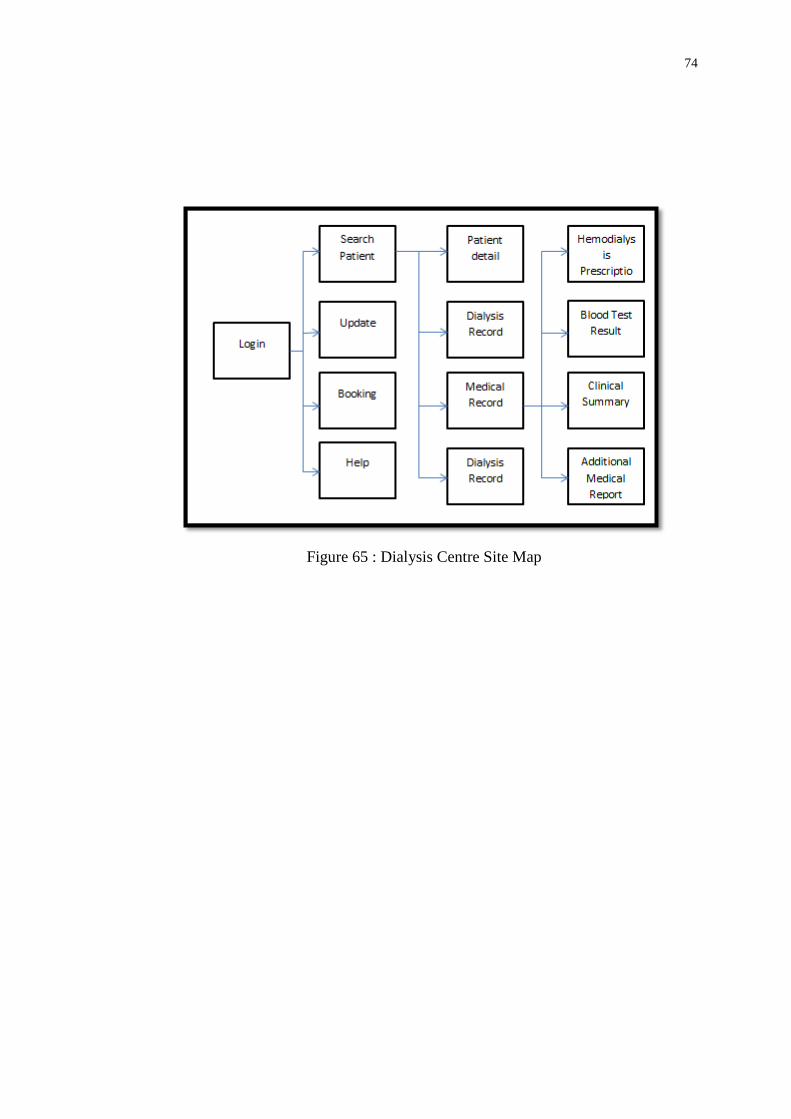
74
Figure 65 : Dialysis Centre Site Map

75
CHAPTER 6
TESTING
6.1 Introduction
Software reliability means the probability of the operation of a system that is free of
failure. Testing is one of the effective ways to measure software reliability. Software
testing is used to analyze and detect the differences between existing and required
condition and evaluate the features of the application. Black box testing and white
box testing techniques are used to test the application. Black box testing is often used
for validation while white box testing is used for verification. Black box testing
ignores the internal coding and internal logic of the program and focus solely on the
output that generated in response to selected inputs and execution conditions. On the
other hand, the white box testing takes into account the internal coding and internal
logic of a system or component according to IEEE Standard Glossary of Software
Engineering Terminology (1990).
During the testing phase for this Dialysis Data Management system, unit
testing, integration testing techniques, functional testing and acceptance testing are
used to ensure the system is fulfilling the requirement and is of expected quality.
Different testing is conducted by different group of people. Basically, programmer
are involved in the unit testing, integration testing techniques and functional testing
during the development and also after completion while the users are involved in the
acceptance testing for this Dialysis Data Management system after the system is
done and ready for deploy.

76
6.2 Unit Testing
According to IEEE Standard Glossary of Software Engineering Terminology (1990),
unit testing is test on the individual hardware, software unit or group of related units.
Based on Narendra Kumar and Rama Mohan Reddy (2011), unit testing is used to
ensure that the code is in accordance with the design specification. Unit testing is
more effective when the construct is more specific to be tested instead of testing the
entire code. Small part of the application is taken out to be tested independently of
the entire application to ensure that the individual parts of the system are working
correctly.
White box testing is used for the test. To ensure the code does what it is
intended to do at a low structure level, test case is used to determine that the code
will provide the desire result. In this system, it is involving of many database query
and ‘if else’ statement. Hence, test case is used to ensure that query to the database is
successful. If there is an ‘if else’ statement, a second test case is used to go down the
path that not executed by the first test case. Besides that, the structure of the code is
examined by reading the code itself to find the error that might exist in the system
without knowing. Below is some part of the codes that are tested by unit testing.
Figure 66 : Part of code used Unit Testing
During the unit testing of this part of code, the user is required to select user
type. If the type is patient, the page will login the user to the patient home page base
on the user id. On the other hand, the page will login the user to the dialysis home
page if the user type is not patient.

77
Besides that, unit testing is also used to test for the connection to the database.
Figure 67 : Part of code used to test Database Connectivity.
If the database is failed to connect, the website will display that the SQL is
failed to connect with the error messages.
In order to ensure database queries are correct, unit testing is also used to
check on the database query. Below is one of the parts that used unit testing to test
for the database query.
Figure 68 : Part of the Select Statement used in Unit Testing
The result of the unit testing was satisfied. With the testing of each possible
path of each individual unit, it was assured that the functionality of the system is
working fine and perfectly. Bugs that encountered are identified and fixed
immediately during the testing.

78
6.3 Integration Testing
According to IEEE Standard Glossary of Software Engineering Terminology (1990),
integration testing is combining the software components and hardware components
together and tested to evaluate the interaction between them. Integration testing is
being done after the unit testing. Technique that used for this testing is black box and
white box testing.
The main objective of this integration test is to ensure that the units of the
system are able to work together when they are integrated with larger code base.
During this test, the data is examined to ensure that the data and messages are pass
correctly across and interface and also make sure that the interface are implemented
as specified. Besides that, the predetermined inputs were also passed into the system
and the output that received is compared to ensure that the result is correct. For this
system, there is consisting of insert, update and delete from the database as well as
passing the information across different pages. Hence, the data are checked to ensure
that these data are passing or updated correctly into the database.
Below is some part of the system that is tested by integration testing:
Figure 69 : Screenshot of the form where the dialysis centre enters the patient’s
identity number.

79
Figure 70 : Screen shot of request permission screen
During the integration testing, the patient’s identity number is required
whether it is exist in the database. After checking for the patient’s identity in the
patient database, the system is required to check whether the dialysis centre has the
rights to access the patient information. If the dialysis center does not have the right
to access the patient information, the system will send the patient an email to get the
acknowledgement from the patient and get the approval from the patient. During this
integration testing, the data passing and the database query is integrated in order to
run the test.
Figure 71 : Part of code that sends the identity number to check for the access
permission.

80
Figure 72 : Part of the code used to send notification email to patient.
Besides that, here is another example that used integration testing.
Figure 73 : Screen shot of the button click to convert data into PDF format
Figure 74 : PHP function that enables to convert data into PDF format
During the integration testing, print PDF function, database query function and the
data passing is integrated into the system. When the dialysis center clicked on the
print document button, the data that required is passed in order to print out the
information that required. Hence, the information that printed out is checked to
determine whether the data is passed correctly and fulfilled the customer’s
requirement.

81
Figure 75 : Screen shot of the PDF document generated.
The bugs that encountered are identified during the integration testing and have been
fixed once using the Integration testing.
6.4 Functional Testing
IEEE Standard Glossary of Software Engineering Terminology (1990) explained that
functional testing ignores the internal mechanism of a system or component and
focuses on the output of the system with the selected inputs and execution conditions
Functional testing is done on the whole system. It ensures that the system
fulfill the functionality specified in the requirement specification work.
Test case To access a dialysis patient’s personal data that has been visited the
dialysis centre by the nurse of a dialysis centre.
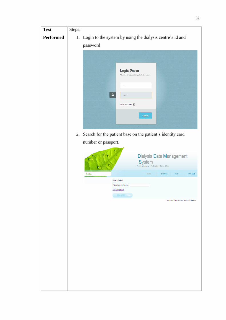
82
Test
Performed
Steps:
1. Login to the system by using the dialysis centre’s id and
password
2. Search for the patient base on the patient’s identity card
number or passport.

83
3. Once the patient’s identity card number or passport is entered,
the detail of the patient will be displayed.
4. Return to the home page by clicking on the Home button or log
out from the user by clicking log out button.
Expected
Result
1. When the dialysis centre’s nurse login into the system, it will
appear the home page for dialysis centre where the nurse can
enters the patient’s identity card number or passport number.
2. After the nurse enters the patient’s identity card number or
passport number, the patient’s detail is displayed.
3. The nurse clicks on the home button to go back to the Home
page and log out the system by clicking on the log out button.
Actual
Result
1. The dialysis centre’s nurse login into the system and entered to
the main page for the dialysis center.
2. The nurse entered the patient’s identity card number or
passport number and the patient’s detail is displayed.
3. The nurse clicked to the Home button to go back the home
page and clicked the logout button to log out from the system.
Pass/Fail Pass

84
Test case To access a dialysis patient’s personal data who has not been visit the
dialysis centre by the nurse of a dialysis centre.
Test
Performed
Steps:
1. Login to the system by using the dialysis centre’s id and
password and search for the patient that has not been visited the
dialysis centre before base on the patient’s identity card number
or passport.
2. The system will show that the dialysis centre does not have the
right to access the patient’s information. Email is required to
send to notify the patient in order to access the data.

85
3. Click on the Get Approval button, the email will send to the
user.
Expected
Result
1. When the dialysis centre’s nurse login into the system, it will
appear the home page for dialysis centre where the nurse can
enter the patient’s identity card number or passport number.
2. After the patient identity card number or passport number that
has not been visited the dialysis centre is enter, a notification
will display to show that the dialysis centre does not have the
right to access the patient’s information. An email is required to
send to notify the patient in order for the nurse to access the
data.
3. The nurse clicks Get Approval button, a notification email will
send to the patient.
Actual
Result
1. The dialysis centre’s nurse login into the system and entered to
the main page for the dialysis center.
2. The nurse entered the patient’s identity card number or passport
number that has not been visited the dialysis centre is enter. A
notification was displayed to show that the dialysis centre does
not have the right to access the patient’s information.
3. The nurse clicked Get Approval button, a notification email was
send to the patient.
Pass/Fail Pass

86
Test case To add a new patient by the nurse of a dialysis center
Test
Performed
Steps:
1. Login to the system by using the dialysis centre’s id and
password and click on the Add New Patient link.
2. The system will show the patient’s personal detail form.

87
3. Next, the system will show the patient’s haemodialysis
prescription form.
4. Next, the system will show the patient’s Clinical Summary
form.
5. Go back to home page and find the patient to ensure that the
patient is successfully entered into the system.
Expected
Result
1. After the nurse login to the system, the nurse clicks on the Add
New Patient link. It will link to the patient’s personal detail

88
form.
2. After the nurse enters all the patient’s personal detail, the
system will link to the patient’s haemodialysis prescription
form.
3. After the nurse enters all the patient’s haemodialysis
prescription, the system will link to the patient’s Clinical
Summary form.
4. After the nurse enters the patient’s Clinical Summary, the
system will go back to the home page. The nurse is required to
search back the patient to ensure that the patient’s detail is
successfully entered into the system.
Actual
Result
1. After the nurse login to the system, the nurse clicked on the
Add New Patient link. The patient’s personal detail form is
displayed.
2. After the nurse entered all the patient’s personal detail, patient
haemodialysis prescription form is displayed.
3. After the nurse entered all the patient’s haemodialysis
prescription, patient’s Clinical Summary form is displayed.
4. After the nurse enters the patient’s Clinical Summary, the nurse
searched back the patient and the patient was successfully
entered into the system.
Pass/Fail Pass
Test case To access a dialysis patient’s blood test result by the nurse of a dialysis
centre
Test
Performed
Steps:
1. Login to the system by using the dialysis centre’s id and password
and search for the particular patient.

89
2. Click on the Blood Test Result at the side menu or click on Blood
Test Result link below the patient’s detail.
3. Next, the system will show all the blood test report based on the
date and lab number.
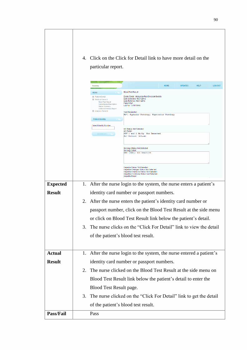
90
4. Click on the Click for Detail link to have more detail on the
particular report.
Expected
Result
1. After the nurse login to the system, the nurse enters a patient’s
identity card number or passport numbers.
2. After the nurse enters the patient’s identity card number or
passport number, click on the Blood Test Result at the side menu
or click on Blood Test Result link below the patient’s detail.
3. The nurse clicks on the “Click For Detail” link to view the detail
of the patient’s blood test result.
Actual
Result
1. After the nurse login to the system, the nurse entered a patient’s
identity card number or passport numbers.
2. The nurse clicked on the Blood Test Result at the side menu on
Blood Test Result link below the patient’s detail to enter the
Blood Test Result page.
3. The nurse clicked on the “Click For Detail” link to get the detail
of the patient’s blood test result.
Pass/Fail Pass
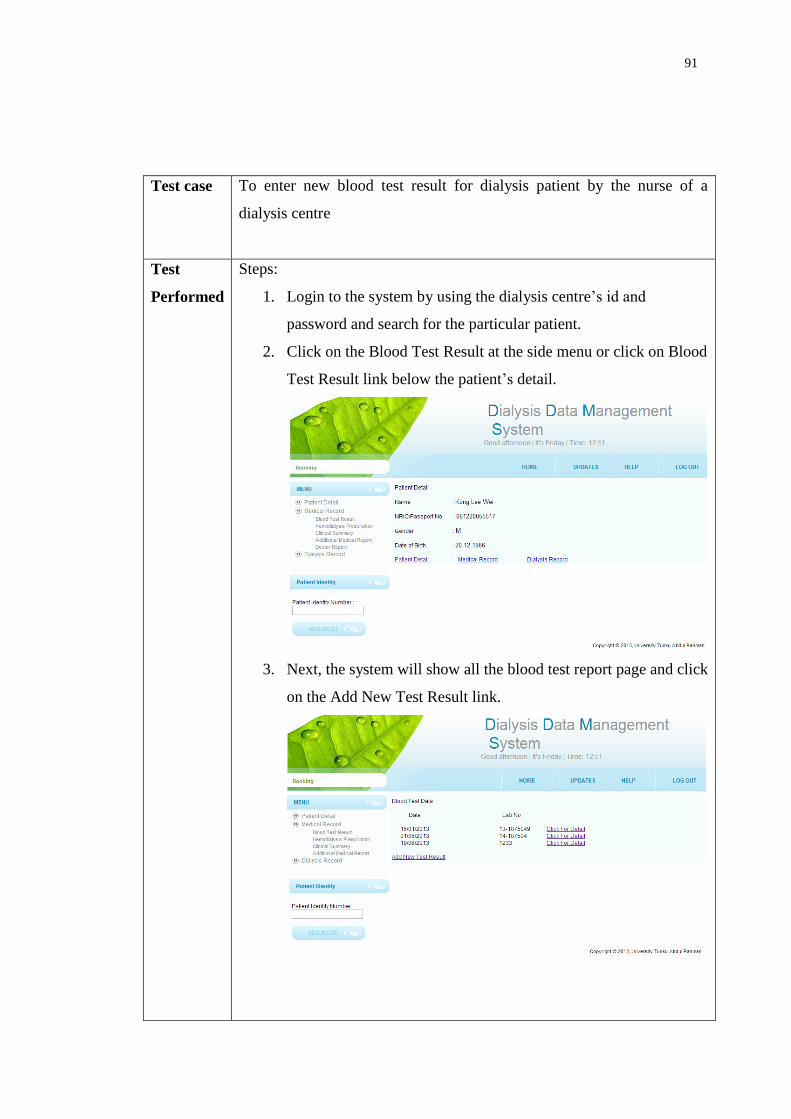
91
Test case To enter new blood test result for dialysis patient by the nurse of a
dialysis centre
Test
Performed
Steps:
1. Login to the system by using the dialysis centre’s id and
password and search for the particular patient.
2. Click on the Blood Test Result at the side menu or click on Blood
Test Result link below the patient’s detail.
3. Next, the system will show all the blood test report page and click
on the Add New Test Result link.

92
4. Next, the system will show the patient Add New Blood Test
form.
5. Go back to Blood Test Result page to ensure that the new Blood
Test Report is successfully entered into the system.
Expected
Result
1. After the nurse login to the system, the nurse enters a patient’s
identity card number or passport numbers.
2. After the nurse enters the patient’s identity card number or
passport number, click on the Blood Test Result at the side menu
or click on Blood Test Result link below the patient’s detail to
view for the patient Haemodialysis Prescription detail.
3. The nurse clicks on the Add New Blood Test Result to enter the
new blood test report into the system.
4. After the nurse enters the patient’s new Blood Test Result into

93
the system. The nurse is required to go back to Blood Test Result
page to ensure that the new Blood Test Report is successfully
entered into the system.
Actual
Result
1. After the nurse login to the system, the nurse entered a patient’s
identity card number or passport numbers.
2. The nurse clicked on the Blood Test Result at the side menu and
Blood Test Result link below the patient’s detail to enter the
Blood Test Result page.
3. The nurse clicked the Add New Blood Test Result to enter the
new blood test report into the system.
4. The nurse went back to back to Blood Test Result page to ensure
that the new Blood Test Report is successfully entered into the
system.
Pass/Fail Pass
Test case To access a dialysis patient’s haemodialysis prescription by the
nurse of a dialysis centre
Test
Performed
Steps:
1. Login to the system by using the dialysis centre’s id and
password and search for the particular patient.

94
2. Click on the Haemodialysis Prescription at the side menu or
click on Haemodialysis Prescription link below the patient’s
detail.
3. Next, the system will show the patient’s Haemodialysis
Prescription report.
Expected
Result
1. After the nurse login to the system, the nurse enters a
patient’s identity card number or passport numbers.
2. After the nurse enters the patient’s identity card number or
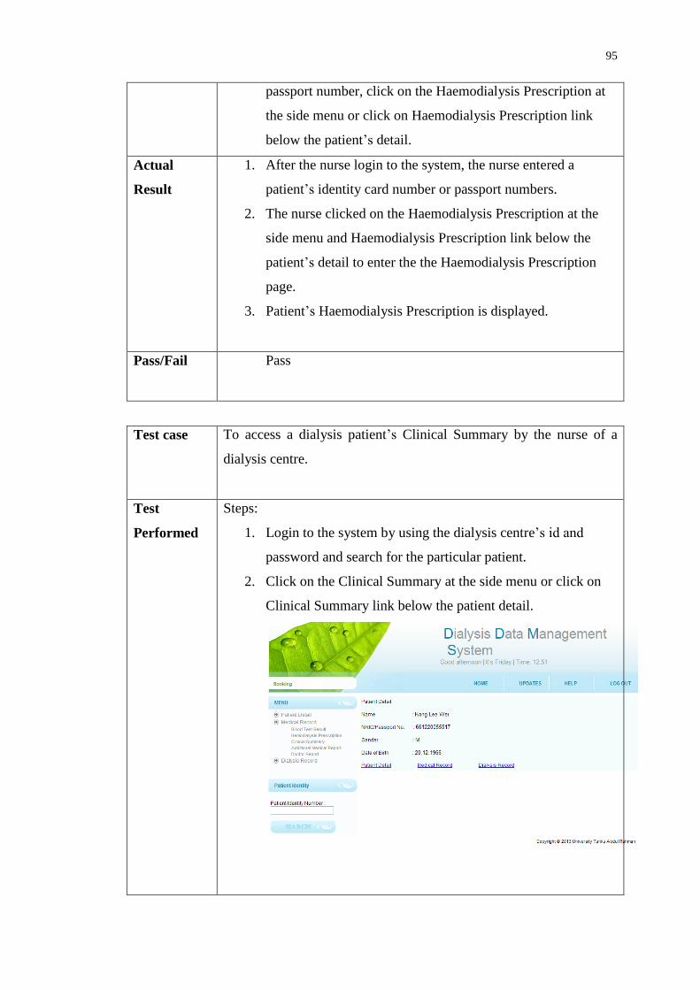
95
passport number, click on the Haemodialysis Prescription at
the side menu or click on Haemodialysis Prescription link
below the patient’s detail.
Actual
Result
1. After the nurse login to the system, the nurse entered a
patient’s identity card number or passport numbers.
2. The nurse clicked on the Haemodialysis Prescription at the
side menu and Haemodialysis Prescription link below the
patient’s detail to enter the the Haemodialysis Prescription
page.
3. Patient’s Haemodialysis Prescription is displayed.
Pass/Fail Pass
Test case To access a dialysis patient’s Clinical Summary by the nurse of a
dialysis centre.
Test
Performed
Steps:
1. Login to the system by using the dialysis centre’s id and
password and search for the particular patient.
2. Click on the Clinical Summary at the side menu or click on
Clinical Summary link below the patient detail.

96
3. Next, the system will show the patient’s Clinical Summary
report.
Expected
Result
1. After the nurse login to the system, the nurse enters a
patient’s identity card number or passport numbers.
2. After the nurse enters the patient’s identity card number or
passport number, click on the Clinical Summary at the side
menu or click on Clinical Summary link below the patient’s
detail.
Actual
Result
1. After the nurse login to the system, the nurse entered a
patient’s identity card number or passport numbers.
2. The nurse clicked on the Clinical Summary at the side menu
and Clinical Summary link below the patient’s detail to enter
the Clinical Summary page.
3. Patient Clinical Summary is displayed.
Pass/Fail Pass
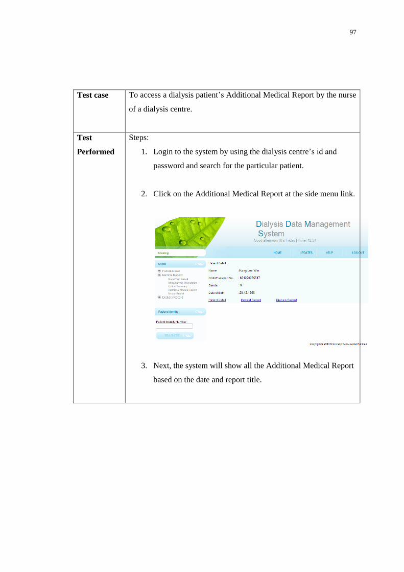
97
Test case To access a dialysis patient’s Additional Medical Report by the nurse
of a dialysis centre.
Test
Performed
Steps:
1. Login to the system by using the dialysis centre’s id and
password and search for the particular patient.
2. Click on the Additional Medical Report at the side menu link.
3. Next, the system will show all the Additional Medical Report
based on the date and report title.

98
4. Click on the Click for Detail link to have more detail on the
particular report.
Expected
Result
1. After the nurse login to the system, the nurse enters a
patient’s identity card number or passport numbers.
2. After the nurse enters the patient’s identity card number or
passport number, click on the Additional Medical Report at
the side menu.
3. The nurse clicks on the “Click For Detail” link to view the
detail of the patient’s additional medical report.

99
Actual
Result
1. After the nurse login to the system, the nurse entered a
patient’s identity card number or passport numbers.
2. The nurse clicked on the Additional Medical Report at the
side menu.
3. The nurse clicked on the “Click for Detail” link to get the
detail of the patient’s Additional Medical Report.
Pass/Fail Pass
Test case To enter new additional medical report for dialysis patient by the nurse
of a dialysis centre.
Test
Performed
Steps:
1. Login to the system by using the dialysis centre’s id and
password and search for the particular patient.
2. Click on the Additional Medical Report at the side.

100
3. Next, the system will show all the additional medical report and
click on the Add New Test Result link.
4. Next, the system will show the patient’s Additional Medical
Report form.
5. Go back to Additional Medical Report page to ensure that the
new medical report is successfully entered into the system.

101
Expected
Result
1. After the nurse login to the system, the nurse enters a patient’s
identity card number or passport numbers.
2. After the nurse enters the patient’s identity card number or
passport number, click on the Additional Medical Report at the
side to view for the patient’s Haemodialysis Prescription detail.
3. The nurse clicks on the Add New Test Result to enter the new
medical report into the system.
4. After the nurse enters the patient’s new medical report into the
system. The nurse is required to go back to Additional Medical
Report page to ensure that the new medical report is successfully
entered into the system.
Actual
Result
1. After the nurse login to the system, the nurse entered a patient’s
identity card number or passport numbers.
2. The nurse clicked on the Additional Medical Report at the side
menu to enter the Additional Medical Report page.
3. The nurse clicked the Additional Medical Report to enter the new
medical report into the system.
4. The nurse went back to back to Additional Medical Report page
to ensure that the new medical report is successfully entered into
the system.
Pass/Fail Pass
Test case To access and print a dialysis patient’s Dialysis Record by the nurse of a
dialysis centre.
Test
Performed
Steps:
1. Login to the system by using the dialysis centre’s id and
password and search for the particular patient.

102
2. Click on the Dialysis Record at the side menu link or click on the
dialysis record link below the patient’s detail.
3. Next, the system will show all the Dialysis Record based on the
date.
4. Click on the Click for Detail link to have more detail on the
particular report.

103
5. Click on the Print Document button to print the information.
Expected
Result
1. After the nurse login to the system, the nurse enters a patient’s
identity card number or passport numbers.
2. After the nurse enters the patient’s identity card number or
passport number, click on the Dialysis Record at the side menu
and the Dialysis Record link below the patient’s detail to enter
the Dialysis Record page.
3. The nurse clicks on the “Click For Detail” link to view the detail
of the patient’s dialysis record.
4. The nurse clicks on the “Print Document” button to print the
patient’s dialysis record.
Actual
Result
1. After the nurse login to the system, the nurse entered a patient’s
identity card number or passport numbers.

104
2. The nurse clicked on the Additional Medical Report at the side
menu and the Dialysis Record link below the patient detail to
enter the Dialysis Record page.
3. The nurse clicked on the “Click for Detail” link to view the detail
of the patient’s dialysis record.
4. The nurse clicked on the “Print Document” button and the
dialysis record is printed.
Pass/Fail Pass
Test case To enter new additional medical report for dialysis patient by the nurse
of a dialysis centre.
Test
Performed
Steps:
1. Login to the system by using the dialysis centre’s id and
password and search for the particular patient.
2. Click on the Additional Medical Report at the side.
3. Next, the system will show all the additional medical report
and click on the Add New Test Result link.

105
4. Next, the system will show the patient’s Additional Medical
Report form.
5. Go back to Additional Medical Report page to ensure that the
new medical report is successfully entered into the system.
Expected
Result
1. After the nurse login to the system, the nurse enters a patient’s
identity card number or passport numbers.
2. After the nurse enters the patient’s identity card number or

106
passport number, click on the Additional Medical Report at the
side to view for the patient Haemodialysis Prescription detail.
3. The nurse clicks on the Add New Test Result to enter the new
medical report into the system.
4. After the nurse enters the patient’s new medical report into the
system. The nurse is required to go back to Additional Medical
Report page to ensure that the new medical report is
successfully entered into the system.
Actual
Result
1. After the nurse login to the system, the nurse entered a
patient’s identity card number or passport numbers.
2. The nurse clicked on the Additional Medical Report at the side
menu to enter the Additional Medical Report page.
3. The nurse clicked the Additional Medical Report to enter the
new medical report into the system.
4. The nurse went back to back to Additional Medical Report
page to ensure that the new medical report is successfully
entered into the system.
Pass/Fail Pass
Test case To access and print a dialysis patient’s Dialysis Record by the nurse of
a dialysis centre.
Test
Performed
Steps:
1. Login to the system by using the dialysis centre’s id and
password and search for the particular patient.
2. Click on the Dialysis Record at the side menu link or click on
the dialysis record link below the patient’s detail.

107
3. Next, the system will show all the Dialysis Record based on the
date.
4. Click on the Click for Detail link to have more detail on the
particular report.

108
5. Click on the Print Document button to print the information.
Expected
Result
1. After the nurse login to the system, the nurse enters a patient’s
identity card number or passport numbers.
2. After the nurse enters the patient’s identity card number or
passport number, click on the Dialysis Record at the side menu
and the Dialysis Record link below the patient’s detail to enter
the Dialysis Record page.
3. The nurse clicks on the “Click For Detail” link to view the
detail of the patient’s dialysis record.
4. The nurse clicks on the “Print Document” button to print the
patient’s dialysis record.
Actual
Result
1. After the nurse login to the system, the nurse entered a
patient’s identity card number or passport numbers.
2. The nurse clicked on the Additional Medical Report at the side
menu and the Dialysis Record link below the patient’s detail to

109
enter the Dialysis Record page.
3. The nurse clicked on the “Click for Detail” link to view the
detail of the patient’s dialysis record.
4. The nurse clicked on the “Print Document” button and the
dialysis record is printed.
Pass/Fail Pass
Test case To enter new dialysis record for dialysis patient by the nurse of a dialysis
centre.
Test
Performed
Steps:
1. Login to the system by using the dialysis centre’s id and
password and search for the particular patient.
2. Click on the Dialysis Record at the side menu link or click on the
dialysis record link below the patient’s detail.
3. Next, the system will show all the Dialysis Record based on the
date and click on the Add New Record link.

110
4. Next, the system will show the patient’s Additional Medical
Report form.
5. Go back to Dialysis Record page to ensure that the new dialysis
record is successfully entered into the system.
Expected
Result
1. After the nurse login to the system, the nurse enters a patient’s
identity card number or passport numbers.

111
2. After the nurse enters the patient’s identity card number or
passport number, click on the Dialysis Record at the side or click
on the dialysis record link below the patient’s detail to view for
the patient Dialysis Record.
3. The nurse clicks on the Add New Record to enter the new
dialysis record into the system.
4. After the nurse enters the patient’s new dialysis record into the
system. The nurse is required to go back to Dialysis Record page
to ensure that the new dialysis record is successfully entered into
the system.
Actual
Result
1. After the nurse login to the system, the nurse entered a patient’s
identity card number or passport numbers.
2. The nurse clicked on the Dialysis Record Report at the side menu
or click on the dialysis record link below the patient’s detail to
enter the Dialysis Record page.
3. The nurse clicked the Add New Record to enter the patient’s new
dialysis record into the system.
4. The nurse went back to back to Dialysis Record page to ensure
that the new dialysis record is successfully entered into the
system.
Pass/Fail Pass
Test case To view booking / Reject Booking / Confirm Booking.
Test
Performed
Steps:
1. Login to the system by using the dialysis centre’s id and password.
2. Click on the Booking link on the header menu to view all the
pending booking.
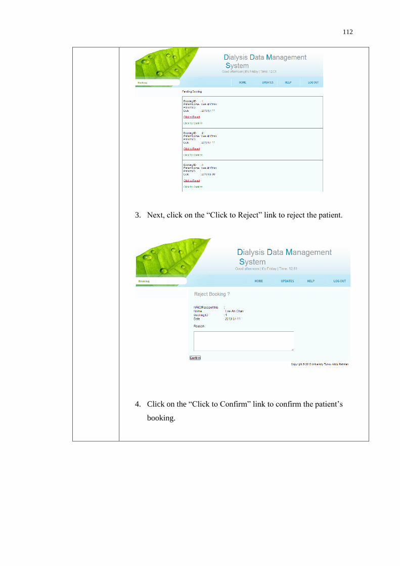
112
3. Next, click on the “Click to Reject” link to reject the patient.
4. Click on the “Click to Confirm” link to confirm the patient’s
booking.

113
5. Click on the “View All Booking” link to view all the confirm
booking.
Expected
Result
1. After the nurse login to the system, click on the booking link at the
top menu to view all the pending booking.
2. The nurse clicks on the “Click to Reject” link to reject the patient
with a reason.

114
3. The nurse clicks on the “Click to Confirm” link to confirm the
patient’s booking and also specify the time of the treatment.
4. The nurse clicks on the “View All Booking” link to view all the
confirm booking for the dialysis centre.
Actual
Result
1. After the nurse login to the system then clicked on the booking link
to enter the booking page to view all the pending booking.
2. The nurse clicked on the “Click to Reject” link to reject the patient
with a reason of fully booking.
3. The nurse clicked on the “Click to Confirm” to confirm the
patient’s booking and also specified the time of the treatment.
4. The nurse clicked on the “View All Booking” link to view all the
confirm booking of the dialysis centre.
Pass/Fail Pass
Test case To access a patient’s personal information by a dialysis patient.
Test
Performed
Steps:
1. Login to the system by using the patient’s id and password to
enter the patient view main page.

115
2. Click on the “More” at the personal icon at the main page to
view and edit their personal detail.
Expected
Result
1. When the dialysis patient login into the system, it will appear the
home page for patient. The patient clicks on “More” at the
personal icon to view and edit their personal detail
2. The patient edits their personal information and clicks save to
save the edited information.
3. The patient goes back to Personal Information page to view the
edited information to ensure the information is corrected.
Actual
Result
1. The patient login into the system. The patient clicked on the
“More” button at the personal icon to view for their information.
2. The patient edited their information and clicked “Saved” icon to
save the edit information.
3. The patient went back to the Personal Information page to view
the edited information to ensure the information is corrected.
Pass/Fail Pass

116
Test case To view a patient’s blood test result by a dialysis patient.
Test
Performed
Steps:
1. Login to the system by using the patient’s id and password to enter
the patient view main page.
2. Click on the “More” at the Medical Record icon at the main page.
3. Click on Blood Test Result to view the patient’s blood test result.
The system will show all the blood test report based on the date
and lab number.

117
4. Click on the Click for Detail link to have more detail on the
particular report.
Expected
Result
1. When the dialysis patient login into the system, it will appear the
home page for patient. The patient clicks on “More” at the Medical
Record icon to enter the medical page.
2. The patient clicks on the Blood Test Result link to view all the
blood test report based on the date and lab number.
3. The patient clicks on the Click for Detail link to have more detail
on the particular report.
Actual
Result
1. The patient login into the system. The patient clicked on the
“More” button at the Medical Record icon to enter the medical
page.
2. The patient clicked on the Blood Test Result link to view all the
blood test report based on the date and lab number.
3. The patient clicked on the Click for Detail link to view the detail
on the particular report.
Pass/Fail Pass

118
Test case To view a patient’s Addition Medical Report by a dialysis patient.
Test
Performed
Steps:
1. Login to the system by using the patient’s id and password to enter
the patient view main page.
2. Click on the “More” at the Medical Record icon at the main page.
3. Click on Additional Medical Report to view the patient’s medical
report. The system will show all the medical report based on the
date and report title.
4. Click on the Click for Detail link to have more detail on the
particular report.
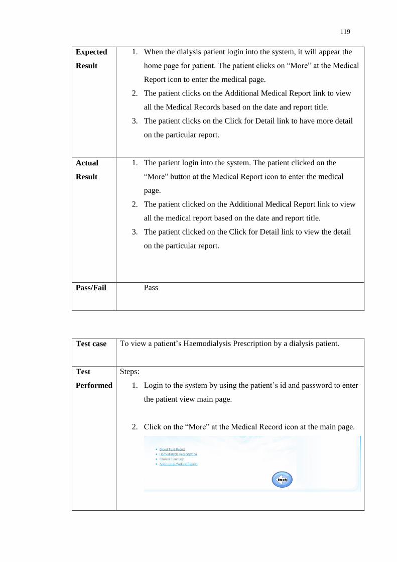
119
Expected
Result
1. When the dialysis patient login into the system, it will appear the
home page for patient. The patient clicks on “More” at the Medical
Report icon to enter the medical page.
2. The patient clicks on the Additional Medical Report link to view
all the Medical Records based on the date and report title.
3. The patient clicks on the Click for Detail link to have more detail
on the particular report.
Actual
Result
1. The patient login into the system. The patient clicked on the
“More” button at the Medical Report icon to enter the medical
page.
2. The patient clicked on the Additional Medical Report link to view
all the medical report based on the date and report title.
3. The patient clicked on the Click for Detail link to view the detail
on the particular report.
Pass/Fail Pass
Test case To view a patient’s Haemodialysis Prescription by a dialysis patient.
Test
Performed
Steps:
1. Login to the system by using the patient’s id and password to enter
the patient view main page.
2. Click on the “More” at the Medical Record icon at the main page.

120
3. Click on Haemodialysis Prescription to view the patient’s
haemodialysis prescription report.
Expected
Result
1. When the dialysis patient login into the system, it will appear the
home page for patient. The patient clicks on “More” at the Medical
Report icon to enter the medical page.
2. The patient clicks on the Haemodialysis Prescription link to view
all the Haemodialysis Prescription report of the patient.
Actual
Result
1. The patient login into the system. The patient clicked on the
“More” button at the Medical Report icon to enter the medical
page.
2. The patient clicked on the Haemodialysis Prescription link to view
all the Haemodialysis Prescription of the patient.
Pass/Fail Pass
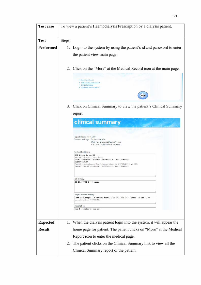
121
Test case To view a patient’s Haemodialysis Prescription by a dialysis patient.
Test
Performed
Steps:
1. Login to the system by using the patient’s id and password to enter
the patient view main page.
2. Click on the “More” at the Medical Record icon at the main page.
3. Click on Clinical Summary to view the patient’s Clinical Summary
report.
Expected
Result
1. When the dialysis patient login into the system, it will appear the
home page for patient. The patient clicks on “More” at the Medical
Report icon to enter the medical page.
2. The patient clicks on the Clinical Summary link to view all the
Clinical Summary report of the patient.

122
Actual
Result
1. The patient login into the system. The patient clicked on the
“More” button at the Medical Report icon to enter the medical
page.
2. The patient clicked on the Clinical Summary link to view all the
Clinical Summary of the patient.
Pass/Fail Pass
Test case To view a patient’s Dialysis Record by a dialysis patient.
Test
Performe
d
Steps:
1. Login to the system by using the patient’s id and password to
enter the patient view main page.
2. Click on the “More” at the Dialysis Record icon at the main
page. The system will show all the dialysis record based on the
date.
3. Click on the “Date” link to have more detail on the particular
report.

123
Expected
Result
1. When the dialysis patient login into the system, it will appear
the home page for patient. The patient clicks on “More” at the
Dialysis Record icon to enter the dialysis record page.
2. The patient clicks on the date to have more detail on the
particular report.
Actual
Result
1. The patient login into the system. The patient clicked on the
“More” button at the Dialysis Record icon to enter the dialysis
record page.
2. The patient clicked on the date to have more detail on the
particular report.
Pass/Fail Pass
Test case To view a booking status and make booking by a dialysis patient.
Test
Performe
d
Steps:
1. Login to the system by using the patient’s id and password to
enter the patient view main page.
2. Click on the “More” at the Booking icon at the main page.
Select the desire dialysis centre and date that the patient wants
to visit as well as valid reason.
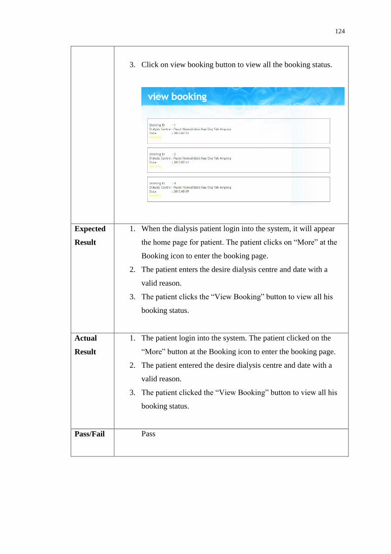
124
3. Click on view booking button to view all the booking status.
Expected
Result
1. When the dialysis patient login into the system, it will appear
the home page for patient. The patient clicks on “More” at the
Booking icon to enter the booking page.
2. The patient enters the desire dialysis centre and date with a
valid reason.
3. The patient clicks the “View Booking” button to view all his
booking status.
Actual
Result
1. The patient login into the system. The patient clicked on the
“More” button at the Booking icon to enter the booking page.
2. The patient entered the desire dialysis centre and date with a
valid reason.
3. The patient clicked the “View Booking” button to view all his
booking status.
Pass/Fail Pass
125
Functional testing is being done after unit testing and integration testing.
During the functional testing, the dialysis center page and the patient page are being
tested in order to make sure that all the requirements are being fulfilled and are
function well. The system is being tested and the system is confirmed that it fulfills
the users’ requirements and scopes.
6.5 Acceptance Testing
Acceptance testing is a formal testing that is conducted by the user or customer to
determine whether the system satisfies its acceptance criteria and allow the customer
to make decision whether to accept the system, explained by IEEE Standard Glossary
of Software Engineering Terminology (1990).
During the acceptance testing, the system is delivered and tested by the
customers. The customers of the system are the dialysis centre’s staff and dialysis
patient. These customers are not trained software tester and runs black box
acceptance based on their expectation on the system. After the customers tested the
system, a questionnaire is given to them to receive the feedback from the customers.
Based on the result of the questionnaire, customers are very satisfied with the
system developed. They gave a very good and positive feedback to the system. This
system has fulfilled their requirements as well as the main objectives of this system
which is data searching, data storing, updating data and facilitate booking services. In
term of ease to use of the system, most of the customers in a opinion that the system
is easy to use but there is some customers have a perception that it is not easy due to
this group of customers are lack of IT knowledge. They hope that this system can be
further improved in order to provide more functionality to the dialysis centres as well
as the patient.
The system is being tested and the system is satisfied by the users and is
ready to be delivered to the users.
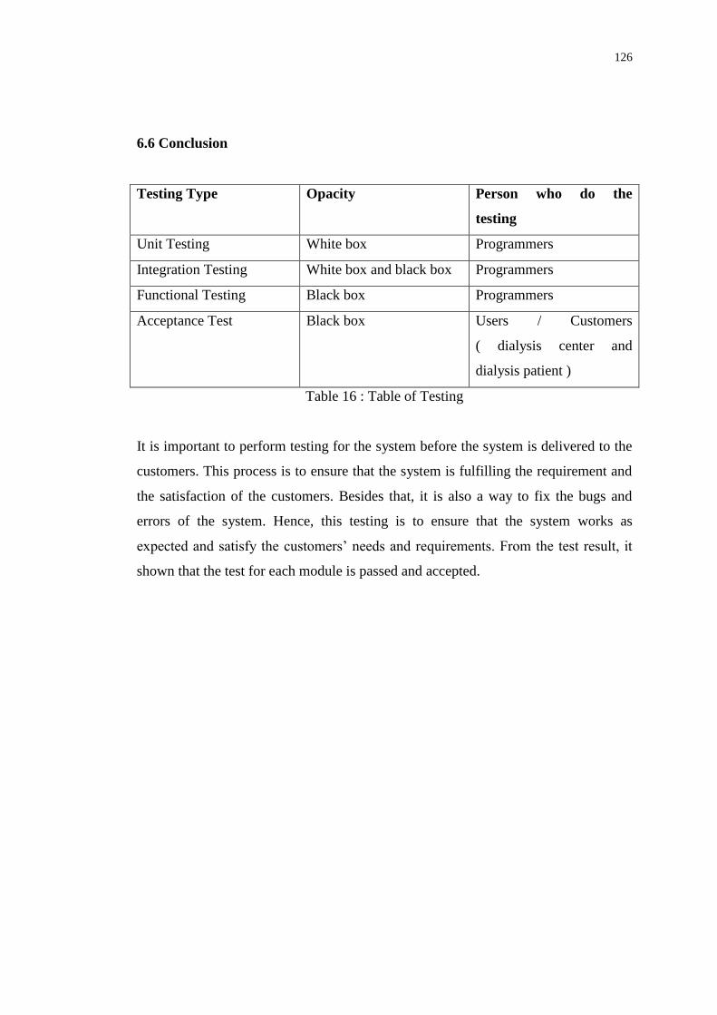
126
6.6 Conclusion
Testing Type Opacity Person who do the
testing
Unit Testing White box Programmers
Integration Testing White box and black box Programmers
Functional Testing Black box Programmers
Acceptance Test Black box Users / Customers
( dialysis center and
dialysis patient )
Table 16 : Table of Testing
It is important to perform testing for the system before the system is delivered to the
customers. This process is to ensure that the system is fulfilling the requirement and
the satisfaction of the customers. Besides that, it is also a way to fix the bugs and
errors of the system. Hence, this testing is to ensure that the system works as
expected and satisfy the customers’ needs and requirements. From the test result, it
shown that the test for each module is passed and accepted.

127
CHAPTER 7
CONCLUSION AND RECOMMENDATION
7.1 Introduction
In the previous chapter, all the information regarding to the system has been
discussed. The information about the objective, problem states, scope, related
projects, design, implementation and testing are all explained in detail during the
previous chapter. Hence, this chapter will give a brief discussion on the overall of the
project.
This chapter will mainly discuss on the contribution of the projects, limitation
and future implementation of this Dialysis Data Management System.
7.2 Contribution of the Projects
The main concern about this project is to facilitate the dialysis patients to manage
their own dialysis data. Currently in Malaysia do not have any system to allow the
dialysis patients to manage their own information together with the dialysis centres.
Hence, wherever the dialysis patients are travel, they are required to request for the
latest patient’s documentation from the patient’s dialysis centre to send their
document through email or fax.

128
There is a true story that told by one of the customer during development of
this project. There was a case that the dialysis patient at Selangor is required to travel
to Johor for a month, so the patient requested the dialysis centre to send the latest
patient’s documentation to the dialysis centre at Johor. Hence, the dialysis centre that
located at Selangor tried to fax and email to the dialysis centre at Johor but failed.
Due to the time constraint, the dialysis centre had no choice but to courier the
document to the dialysis centre at Johor branch. This is kind of troublesome for the
dialysis centres as well as the patients.
This system also facilitates in booking services for the dialysis centres and
the patients. They do not need to call for the dialysis centre to check for booking but
they can make booking just by one click and wait the confirmation of booking from
the dialysis centres.
Due to the advancement of the technology, many things can be simplified and
easy with the use of technology. Besides that, this system not only decreases the
dialysis centres’ paper work and the use of papers but also make their life easier in
managing the patients’ data. On the other hand, in the patients’ point of view, every
data and information is in the patients’ hand. They have their own data wherever they
go. Besides that, the patients also able to make booking and send their information to
the desire dialysis centre easily with the use of this system.
7.3 Limitation of the System
Due to time constraint, there are many parts of the system are needed to be improved
in order to provide the dialysis centres and the patients a perfect system. The
limitations of the system are:
- The security is not strong to protect the patients’ information.
- Every dialysis centres need to have account in the system in order to fully
utilizes the function of the system.

129
- Some information displayed need to be organized in a better way to provide a
better view.
7.4 Future Implementation
For the future implementation, more functionality is needed to be included
into the system in order to make the system as an all rounded system. Currently, the
system only concern in managing the patients’ data and booking. The dialysis centre
was requested to make the system to be connected with the dialysis machine so that it
can automatically update the system without the need of the user to key in the record
manually. Besides that, the dialysis centres also requested the system to be able to
include the billing system to manage the dialysis patients’ bills.
Other than that, the security of the system can be improved by sending a
notification SMS to the patient to provide an additional security in managing the
patients’ data. This system is managing of the patients’ information. Hence, it is
consisting of many privates and confidential information therefore the security is
another main concern in this system.
Lastly, the organisation of the information displayed is needed to be
improved in order to provide a better way to present the information to the users.
Besides that, the system input is also need to be improved so that less input is
required by the users.
130
7.5 Conclusion
Last but not least, the main objective of this system is to facilitate the dialysis centres
and dialysis patients to managing their data. The main objective of the system is
fulfilled and the system is getting a very good and positive feedback from the users
in the way of managing the patient data, less paper work, and eco-friendly due to less
paper is required by using the system. Hence, this system can have further
improvement in order to make the system to be an all rounded system that can
facilitate the users as much as possible.

131
REFERENCES
Baxter. (2013) Dialysis Options.Baxter [Online].Available at
http://www.baxterhealthcare.com.au/patients_and_caregivers/areas_of_expertise/r
enal/treatment_options.html.Accessed on 4th
April 2013, 4:15pm.
Berns, J.S. (2013) Patient information: Hemodialysis (Beyond the Basics). Up To
Date. [Online].Available at http://www.uptodate.com/contents/hemodialysis-
beyond-the-basics.Accessed on 4th
April 2013, 3:10pm.
Bradley Mitchell(n.d.). Apache [Online].Available at
http://compnetworking.about.com/cs/webservers/g/bldef_apache.htm.Accessed on
22nd
Jun 2013, 12.30 pm.
Chien-Hung Liu (2004) Data flow analysis and testing of Java Server
Pages.Computer Software and Applications Conference, 2004. Compsac
2004.Proceedings of the 28th
Annual International.Vol.2 [Online].Available at
http://ieeexplore.ieee.org.libezp.utar.edu.my/stamp/stamp.jsp?tp=&arnumber=134
2689.Accessed on 21st Jun 2013, 1.00 p.m.
Christopher Heng (2010). What is MySQL? What is Database? What is SQL?
[Online].Available at http://www.thesitewizard.com/faqs/what-is-mysql-
database.shtml.Accessed on 22nd
Jun 2013. 11.00a.m
Connolly, T. and Begg, C. (2010) Database Systems: A Practical Approach To
Design, Implementation, and Management. Fifth Edition. Pearson.

132
Core Partners Inc (n.d.). Software Engineering and Professional Services [Online].
Available at http://www.corepartners.com/. Accessed on 18th
May 2013.
11.30a.m..
Dalisay, .M (2013). Scalable and Rapid Application Developmet Using Grails
[Online]. Available at http://www.codeofaninja.com/2013/07/scalable-and-rad-
development-grails.html. Accessed on 22nd
June 2013. 10.10a.m.
Debray, T. (2012). Php vs Asp.net [Online]. Available at
http://www.researchgate.net/post/Php_vs_Aspnet. Accessed on 12 July 2013.
10.00am.
Edraw (2004) [Online]. Flow Chart. Available at
http://www.edrawsoft.com/Flowchart-Definition.php.Accessed on 21st Jun 2013,
12.00 pm.
Fresenius Medical Care. (2012) Therapy Data Management System.Fresenius
Medical Care.[Online].Available at http://russia.fmc-ag.com/files/Br_TDMS-
09.09_GB_w.pdf.Accessed on 2nd
April 2013, 12:45pm.
Fresenius Medical Care. (2012) Therapy Data Management System.Fresenius
Medical Care.[Online].Available athttp://www.fmc-ag.se/files/TDMS_-
_Therapy_Data_Management_System.pdf.Accessed on 14th
April 2013, 8.30pm.
Gambro.(2011) Dialysis Data Management Tool.Gambro.[Online].Available at
http://www.gambro.com/PageFiles/7447/HCEN1292_4_Exalis_%20Dialysis%20
Data%20Management%20Tool.pdf?epslanguage=en.Accessed on 4th
April 2013,
5:15pm.
GJI (2011). GJI Pty Ltd. Available at http://www.gji.com.au/news/article/get-
control-of-your-data-with-icentral/ Accessed on 19nd
Aug 2013. 11.00a.m.
GJI (2013). Data centralised system by GJI Pty Ltd. Available at
http://www.gji.com.au/news/article/get-control-of-your-data-with-icentral/.
Accessed on 20nd
May 2013. 10.00a.m.

133
Govardhan, A. and Nabil Mohammed Ali Munassar. (2010) A Comparison Between
Five Models of Software Engineering. International Journal of Computer Science
Issues, Vol. 7, Issue 5 [Online].Available at http://www.ijcsi.org/papers/7-5-94-
101.pdf.Accessed on 7th
April 2013, 10:30am.
Heeks, R. (1999) Centralised vs. Decentralised Management of Public Information
Systems: A Core-Periphery Solution. School of Environment and Development,
The University of Manchester.[Online].Available at
http://www.sed.manchester.ac.uk/idpm/research/publications/wp/igovernment/doc
uments/igov_wp07.pdf.Accessed on 3rd
April 2013, 10:45am.
Hughes Systique (n.d.). Agile Model [Online]. Available at
http://www.hsc.com/tabid/69/Default.aspx. Accessed on 20nd
Aug 2013.
11.00a.m.
Java (2013). Java Server Pages [Online]. Available at http://www.java.com/en/.
Accessed on 20nd
Aug 2013. 10.10a.m.
Lim, T.O, Lee, D.G and Morad,Z. (2000) Provision of Dialysis in Malaysia. Med J
Malaysia 2000, 55, pp.188-195 [Online]. Available at
http://www.crc.gov.my/documents/Journal/ProvisionOfDialysis.pdf.Accessed on
5th
April 2013, 11:25am.
Malaysian Society Nephrology (2011).19th
Report of the Malaysian Dialysis and
Transplant Registry 2011[Online]. Available at
http://msn.org.my/fwbPagePublic.jsp?fwbPageId=pMdtr2011. Accessed on 21st
June 2013 10.30a.m.
Malaysian Society of Nephrology.(2011) 19th Report of the Malaysian Dialysis and
Transplant Registry 2011.Malaysian Society of Nephrology.[Online].Available at
http://msn.org.my/fwbPagePublic.jsp?fwbPageId=pMdtr2011.Accessed on 2nd
April 2013, 4:25pm.

134
Martin. J (1991). Rapid Application Development. Macmillan Coll Div.
Microsoft Developer Network (n.d.). Active Server Pages [Online].Available at
http://msdn.microsoft.com/en-us/library/aa286483.aspx.Accessed on 21st Jun
2013. 1.30 pm.
Microsoft(2013).ASP.net [Online]. Available at http://www.asp.net. Accessed on
20nd
Aug 2013. 10.00a.m.
Ministry of Health. (2001) Guidelines for private healthcare institutions providing
renal Dialysis: - regulation 4 of the private hospitals and medical Clinics
regulations. Guidelines for Renal Dialysis Centres [Online].Available at
https://www.moh-
ela.gov.sg/ela/content/sps_institutions_providing_renal_dialysis_guidelines.pdf.A
ccessed on 6th
April 2013, 1:25pm.
Ministry of Health. (2012). Haemodialysis Quality And Standards: - Infection
Control Measures. Haemodialysis Quality And Standards [Online]. Available at
http://www.moh.gov.my/images/gallery/Garispanduan/Haemodialysis_Quality_St
andards.pdf.Accessed on 6th
April 2013, 2:45pm.
Narendra Kumar Rao.B. , Rama Mohan Reddy. A, Ravi.k (2011).Level
Dependencies of Individual Entities in Random Unit Testing of Structured
Code.IEEE Xplore [Online].Available at
http://ieeexplore.ieee.org.libezp.utar.edu.my/stamp/stamp.jsp?tp=&arnumber=594
2086&tag=1.Accessed on 24th
Jun 2013. 12.00 pm.
National Kidney Foundation (2013). Diabetes and Kidney Disease [Online].
Available at http://www.kidney.org/atoz/content/diabetes.cfm. Accessed on 19th
May 2013. 11.30a.m..

135
National Renal Registry(2003). 11th
Report of The Malaysian Dialysis & Transparent
Registry 2003 [Online]. Available at
http://www.msn.org.my/Doc/PublicDoc_PB/Publication/nrr_report2003/NRR11re
port.pdf . Accessed on 20nd
Aug 2013. 11.00a.m..
NC DENR System Development Life Cycle Methodology.(1999) Section 6 – Rapid
Application Development Method [Online].Available at
http://portal.ncdenr.org/c/document_library/get_file?uuid=60ae8525-cf9f-417c-
83d9-90d45f726520&groupId=17979.Accessed on 7th
April 2013, 11:30am.
Peterson, K., Wohlin, C. and Dejan Baca. (2009) The Waterfall Model in Large-
Scale Development. PROFES 2009,LNBIP 32 pp.386 - 400 [Online]. Available at
http://www.bth.se/fou/forskinfo.nsf/0/fc0d54aeea5cb8d7c12575c8005fc9d6/$file/
00320386.pdf . Accessed on 7th
April 2013, 10:00am.
Php.net (n.d.). What is PHP? [Online].Available at http://php.net/manual/en/intro-
whatis.php.Accessed on 21st Jun 2013. 2.00p.m.
Php.net(2013). PHP [Online]. Available at http://www.php.net/. Accessed on 20nd
Aug 2013. 10.20a.m.
Rouse, M. (2005). JavaScript [Online]. Available at
http://searchsoa.techtarget.com/definition/JavaScript . Accessed on 22nd
Jun 2013,
12.00 pm.
Rouse, M. (2005). Site map [Online]. Available at
http://searchsoa.techtarget.com/definition/site-map. Accessed on 23th Jun
2013,10.00 am.
Rouse, M. (2005). HTML ( HypertextMarkup Language) [Online]. Available at
http://searchsoa.techtarget.com/definition/HTML .Accessed on 21st Jun 2013, 3.00
pm.

136
Rouse, M. (2005). Site map [Online]. Available at
http://searchsoftwarequality.techtarget.com/definition/systems-development-life-
cycle. Accessed on 23th Jun 2013,10.00 am.
Rouse, M. (2007). Use Case[Online]. Available at
http://searchsoftwarequality.techtarget.com/definition/use-case.Accessed on 21st
Jun 2013, 11.35am.
Sheetal Sharma, Darothi Sarkar and Divya Gupta. (2012) Agile Processes and
Methodologies: A Conceptual Study. International Journal of Computer Science
Issues, Vol. 4, No.5 [Online].Available at
http://www.enggjournals.com/ijcse/doc/IJCSE12-04-05-186.pdf.Accessed on 7th
April 2013, 10:45am.
Sommerville, I. (2004). Software Engineering,7th
edn. Person Education Ltd.,
London. Available at
http://www.bth.se/fou/forskinfo.nsf/0/fc0d54aeea5cb8d7c12575c8005fc9d6/$file/
00320386.pdf. Accessed on 20nd
Aug 2013. 11.00a.m.
The Institute of Electrical and Electronics Engineers (1990). IEEE Standard Glosaary
of Software Engineering Terminology.IEEEXplore[ Online ]. Available at
http://ieeexplore.ieee.org.libezp.utar.edu.my/stamp/stamp.jsp?tp=&arnumber=159
342 .Accessed on 10 August 2013 12.00pm.
The Star.(2013) ‘Pushing for more dialysis clinics’. 20 February 2013, p. 14.
Vishnu Sharma. (n.d.) Waterfall Model and Spiral Model [Online].Available at
http://examengineinfo.airinsoft.in/UploadTutorialFiles/MIS_waterfall%20and%20
spiral%20model.pdf .Accessed on 7th
April 2013, 10:15am.
W3Schools.com (n.d.). CSS Introduction [Online].Available at
http://www.w3schools.com/css/css_intro.asp.Accessed on 22nd
June 2013.
10.00a.m.
Top Related