


Languages
Pages
Legal


Development Bureau CAD Standard for Works Projects V 1.03.00
The Government of the Hong Kong
Special Administrative Region
Development Bureau
CAD Standard for Works Projects
Version 1.03.00
Date of Issue: 20 November 2007

Development Bureau CAD Standard for Works Projects V 1.03.00 Contents
Page
1. INTRODUCTION .........................................................................................................1 1.1. PURPOSE OF THE DOCUMENT.......................................................................1 1.2. APPLICABILITY..................................................................................................1 1.3. CAD SOFTWARE..............................................................................................1
2. PRINCIPLES BEHIND THE CSWP .................................................................................3
3. FOLDERS.....................................................................................................................5 3.1. CSWP COMMON DATA FOLDERS ................................................................5 3.2. PROJECT DATA FOLDERS...............................................................................6
4. FILES ...........................................................................................................................7 4.1. FILE SETTINGS ...................................................................................................7 4.2. DRAWING FILE NAMING ................................................................................7 4.3. MODEL FILE NAMING .....................................................................................8 4.4. AGENT RESPONSIBLE CODES ........................................................................9
5. LAYERS .....................................................................................................................11 5.1. LAYER NAMING.............................................................................................11 5.2. LAYER ASSIGNMENT .....................................................................................12 5.3. ELEMENT CODING TABLES...........................................................................12
6. LINES ........................................................................................................................19 6.1. LINE THICKNESSES..........................................................................................19 6.2. ASSIGNMENT OF LINE THICKNESSES ...........................................................19 6.3. AutoCAD LIN LIBRARY FILE ..........................................................................20 6.4. AutoCAD LTSCALE AND PSLTSCALE SETTING............................................20 6.5. SYMBOLS AND CUSTOM LINESTYLES ..........................................................20
7. TEXT ..........................................................................................................................21 7.1. ENGLISH TEXT .................................................................................................21 7.2. CHINESE TEXT .................................................................................................22 7.3. TEXT ON LANDS DEPARTMENT MAPPING ..................................................23 7.4. SPECIAL CHARACTERS .................................................................................24
8. COLOURS.................................................................................................................25
9. SCALES.....................................................................................................................25 9.1. SCALE OF ORIGINAL CAD DATA................................................................25 9.2. GUIDELINES FOR PLOTTED SCALES .............................................................25
10. PAPER SIZES .............................................................................................................27
11. SYMBOL LIBRARIES ..................................................................................................29
12. CUSTOM LINE-STYLE LIBRARIES...............................................................................31
13. SUMMARY OF REQUIREMENTS................................................................................33 13.1. MANDATORY / USER CHOICE.....................................................................33 13.2. REFERENCES ..................................................................................................35
i

Development Bureau CAD Standard for Works Projects V 1.03.00
This is a blank page
ii

Development Bureau CAD Standard for Works Projects V 1.03.00 Introduction
1 INTRODUCTION
1.1 PURPOSE OF THE DOCUMENT
1.1.1 This document presents the standards to be used in the structuring and naming of CAD data and for creating, editing and plotting drawings under the CAD Standard for Works Projects [CSWP].
1.2 APPLICABILITY
1.2.1 The standards are applicable to all types of drawings produced for works projects, other than presentation drawings. A presentation drawing is defined as being a drawing prepared for a specific one-off purpose, having no relationship with other project drawings, no re-use and for which the use of non-CSWP standard fonts and colours is vital.
1.3 CAD SOFTWARE
1.3.1 The CSWP have been developed to be applied to the CAD software packages currently in use in the Works Departments. These packages are:
• AutoCAD 2000 or higher version.
• Microstation SE and J or higher version.
1.3.2 However, exchange of data between Microstation and AutoCAD 2000 should only be carried out using Microstation J version 7.1.1.36 or a higher version of Microstation J.
1.3.3 The Works Department will specify which package is to be used for each works project.
1

Development Bureau CAD Standard for Works Projects V 1.03.00
This is a blank page
2

Development Bureau CAD Standard for Works Projects V 1.03.00 Principles behind the CSWP
2 PRINCIPLES BEHIND THE CSWP
The CSWP are based on good CAD practice
This section contains a brief description of what is considered to be good CAD practice in the production of drawings, together with some definitions that arise from this, which are referred to later in the document. The CSWP have been developed to support these principles.
CAD is not just an electronic drawing board
The benefits of CAD will be limited if the CAD system is used simply as an electronic drawing board. This simple approach to using CAD sees drawings as single entities, each one unrelated to another and closely mimics traditional drawing office practice. Instead of using a sheet of drawing film, which gets more and more battered as time goes by, the drawing is held as a computer file. From time to time, clean paper copies are made using a plotter. The crucial thing in such a system is that each drawing corresponds to a separate computer file.
CAD is a tool for coordination
CAD can be much more than that. If used correctly it can be a powerful tool for co-ordinating a project and overcoming two fundamental problems that occur in both manual drafting and simple CAD systems used as a manual replacement; namely:
• Lack of edge-matching between sheets for projects that cannot be drawn on a single drawing, and
• Updating of background information issued by another discipline or other party.
How can CAD be used to solve these problems?
An unlimited drawing size
The traditional drawing is limited by the size of the film and the size of the drawing board. CAD files are not so limited. They can represent drawings that are far too big to plot in one piece. A large building or site may therefore be drawn complete in one file and only split up into more useable areas when plotted. In this way drafting and design work is not hindered by sheet boundaries.
There is a slight difficulty in doing this. With the simple approach to CAD, the drawing frame, title and revision notes can be carried in the file and plotted with everything else. This is not possible if the plot is a proportion of a larger drawing.
3

Development BureauPrinciples behind the CSWP CAD Standard for Works Projects V 1.03.00
The best solution is for the CAD system to provide features for plot assembly. A plot is made by selecting areas from any number of drawings, combining and positioning them (perhaps scaling and rotating as well), and plotting as a whole. The master drawings are not modified by this process, and the system remembers the composition and layout of the plot, so reissue is no trouble.
A Co-ordination Model
Once CAD files are used in this way then the concept of a 'drawing' in the traditional sense becomes less important. The computer file is now representing a large part of the building; perhaps an entire floor plan. It is beginning to be used as a co-ordination model of the project.
For the successful co-ordination of project data, it is essential that the data remains unique. Unique data will be maintained by referencing the model files and never copying their data.
Drawings are views of model files
The CAD model principle involves the structuring of the project CAD data into a series of model files and drawing files which are then combined to form the project drawings.
Model Files
Model files are used to store all of the common project data either as 2D or 3D information. The majority of co-ordination work is carried out by combining the model files, through referencing, and establishing clashes etc. It is common practice to split model files up into discipline, categories and zones with the access status of the files being controlled.
The model files are then shared by all disciplines working on the project to co-ordinate and progress their part of the design in parallel with the overall design.
Drawing Files
Drawing files are merely windows on the project model, which record the information necessary to create a specific drawing. Drawing files will contain very little data and little of the production work is carried out in drawing files. Typically they will store annotation e.g. drawing number, title, revision, notes, dimensions and any information which is unique to that particular drawing and is unlikely to be used elsewhere.
The information presented in the drawing file is constructed by referencing the project model files. The degree of information and the appearance of that information which is displayed in the project model files can be controlled for that particular drawing.
The CAD Standards for Works Projects are based on BS 1192-5
These good drawing practice principles are used as the basis for the recommendations made in BS 1192-5:1998 Construction Drawing Practice - Guide For The Structuring And Exchange Of CAD Data. The standard is thorough and well thought out and has been used as the basis for many of the recommendations made in the CSWP.
4

Development Bureau CAD Standard for Works Projects V 1.03.00 Folders
3 FOLDERS
This section addresses:
• Folders to be used for holding CSWP common data;
• Folders to be used for holding project data.
3.1 CSWP COMMON DATA FOLDERS
3.1.1 Each organisation that produces drawings to the CSWP shall create a folder area for holding CSWP data that is common to all projects.
Standard Folder (Directory) Structure common to AutoCAD and Microstation
COMMON
RESOURCES
SYMBOLS
DX
SI
CSWP CSWP
CSWP \ SI
CSWP \ SYMBOLS
CSWP \ RESOURCES
CSWP \ DX
CSWP \ COMMON
Standard CSWP library and other files that are applicable to all projects will be stored in sub-folders under the 'CSWP' folder
The 'Standard Interface' program files will be stored in this sub-folder.
This sub-folder will hold the CSWP drawing symbols libraries - See Section 11.
This sub-folder will store the CSWP resource files such as Template files, Chinese font files (See Section 7.2) and Line-style files (See Section 12)
This sub-folder will store the CSWP standard settings file and mapping tables to be used for data exchange
This sub-folder will store files that are used organisation-wide
5
Development BureauFolders CAD Standard for Works Projects V 1.03.00
3.2 PROJECT DATA FOLDERS
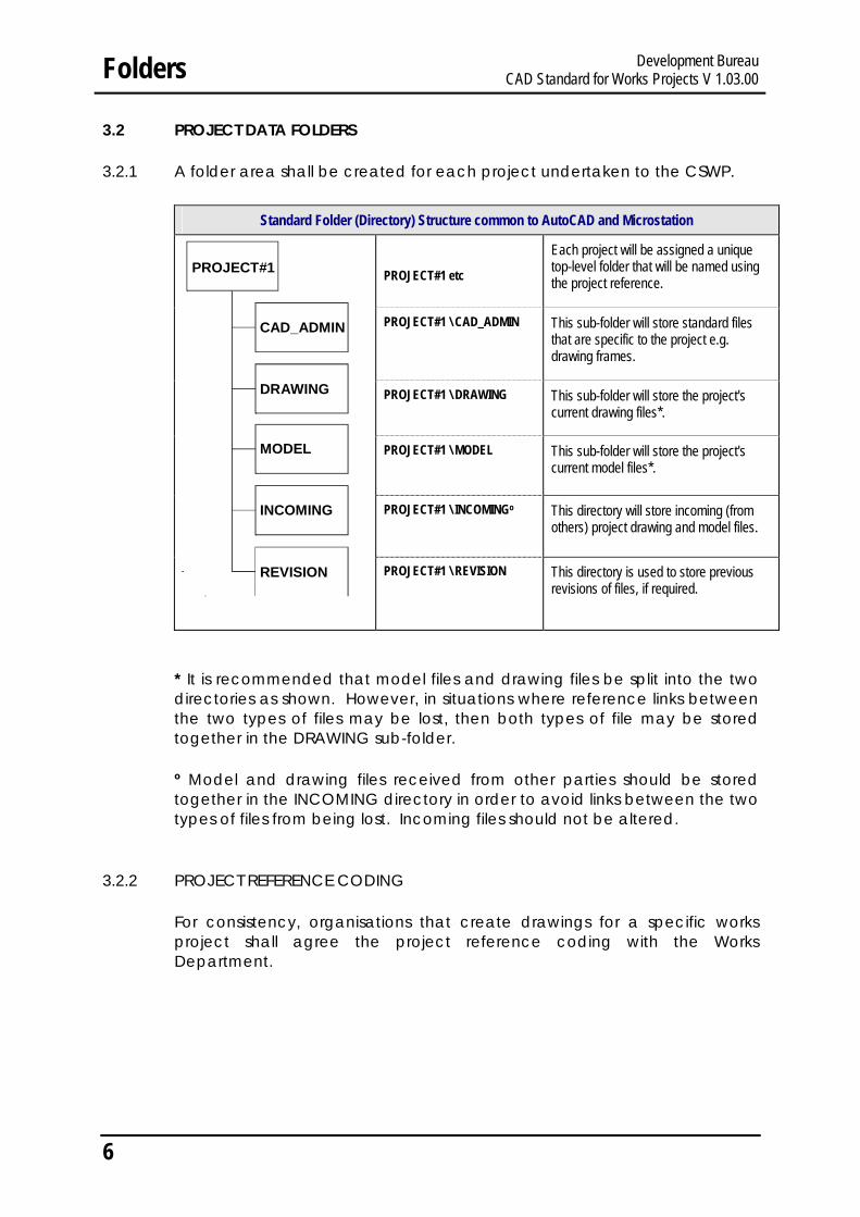
3.2.1 A folder area shall be created for each project undertaken to the CSWP.
Standard Folder (Directory) Structure common to AutoCAD and Microstation
CAD_ADMIN
REVISION
MODEL
DRAWING
INCOMING
PROJECT#1 PROJECT#1 etc
PROJECT#1 \ CAD_ADMIN
PROJECT#1 \ DRAWING
PROJECT#1 \ MODEL
PROJECT#1 \ INCOMINGo
PROJECT#1 \ REVISION
Each project will be assigned a unique top-level folder that will be named using the project reference.
This sub-folder will store standard files that are specific to the project e.g. drawing frames.
This sub-folder will store the project's current drawing files*.
This sub-folder will store the project's current model files*.
This directory will store incoming (from others) project drawing and model files.
This directory is used to store previous revisions of files, if required.
* It is recommended that model files and drawing files be split into the two directories as shown. However, in situations where reference links between the two types of files may be lost, then both types of file may be stored together in the DRAWING sub-folder.
º Model and drawing files received from other parties should be stored together in the INCOMING directory in order to avoid links between the two types of files from being lost. Incoming files should not be altered.
3.2.2 PROJECT REFERENCE CODING
For consistency, organisations that create drawings for a specific works project shall agree the project reference coding with the Works Department.
6

4 FILES
This section addresses:
• File settings when creating new files;
• the naming of (numbered) Drawing Files;
• the naming of Model Files; and
• the assignment of Agent Responsible Codes to be used in model file and layer naming.
AutoCAD
4.2 DRAWING FILE NAMING
Development Bureau CAD Standard for Works Projects V 1.03.00 Files
4.1 FILE SETTINGS
New files shall be created with the following properties:
Microstation
Units Either Metres or Millimetres to suit the type of drawing - User Choice
File Type2D/3D
N/A 3D Microstation Design Files only to be used
WorkingUnits
Default settings
Metres Drawings Millimetres Drawings
Master Units Sub Units Sub Units/Master Units Positional Units/Sub Units
m mm 1000
1
mm -1
1000 Global Origin Default
settings Default Global Origin
X 2,147,483.648 Y 2,147,483.648 Z 2,147,483.648
Drawing File Naming common to AutoCAD and Microstation Users shall maintain their current file naming / numbering convention for drawing files. Normal practice is to name the file with the drawing number. The revision status shall be appended to the end of the filename, with the two fields separated by a hyphen.
A-XXXXXX Revision Status Departments’ Current naming/numbering convention
Note - there is no limit to the number of characters used for drawing file naming
7

Field Characters No. of
Characters
4.3
Development BureauFiles CAD Standard for Works Projects V 1.03.00
MODEL FILE NAMING
Model File Naming common to AutoCAD and Microstation File Names shall be of the form:
HMW-XXXXXXXX-P-HWAYMK-N
Agent Responsible Project Reference
View File ID
Status
If users require previous versions of model files to be kept, copies of each version can be placed in the Revision directory with the revision status appended to the end of the file name. The way to handle revisions in a Drawing Management System may be different.
HMW-XXXXXXXX-P-HWAYMK-N-A
Revision status
Coding
Agent responsible
Alphanumeric 3 - Fixed length
See Section 4.4
Project Reference
Alphanumeric Minimum 1 Maximum 8
User-definable Project reference coding (to be agreed with the Works Department.) Use an underscore if no Project Reference specified
View Alphabetic 1 - Fixed Length
D = detail I = isometric P = plan S = section E = elevation
File ID reference
Alphanumeric Minimum 4, Maximum 8
User definable reference to describe the contents of the model file
Status Alphabetic 1 - Fixed Length
A = As Built E = Existing to remain M = Maintenance / Record N = New Work R = Remove T = Temporary Work W = All Work
Note: Each Field shall be separated by a Hyphen
8

4.4
Development Bureau CAD Standard for Works Projects V 1.03.00 Files
AGENT RESPONSIBLE CODES
Each project participant will be assigned a unique Agent Responsible Code which will have a fixed length of 3 alphanumeric (including ampersands), upper case characters. This code will enable the originator of the data to be identified.
The Agent Responsible Code lists will be administered by the CSWP Working Group. Requests for inclusion in the lists shall be submitted to [email protected] for consideration.
The lists of the Agent Responsible Codes can be downloaded from the Development Bureau web site www.devb-wb.gov.hk/cswp
9

Development Bureau CAD Standard for Works Projects V 1.03.00
This is a blank page
10

Field Characters
Development Bureau CAD Standard for Works Projects V 1.03.00 Layers
5 LAYERS
This section addresses:
• Layer naming;
• the assignment of layers; and
• provides the CSWP Element Coding tables
5.1 LAYER NAMING Common to AutoCAD and Microstation
Layer Naming Convention
User definable
Agent responsible Element
ADA
Coding
Agent responsible 3 (alphanumeric) See Section 4.4
Element 4 (numeric) From the CSWP Element Coding Tables
See Element Coding Tables in Section 5.3
User definable 1 (alphanumeric) User definable alphanumeric character.
Note: Underscore characters must be used to represent empty/unused characters
5.1.1 USE OF THE ELEMENT CODING TABLES
There are three ways in which the element coding can be applied, the choice of which will depend on the degree to which it is required to break down the project data:
Example 1
Group the generic elements under the first number in each main class, e.g.
210_ can be used for all external wall elements.
Example 2
Group elements under their particular sub-class. e.g.
211_ Load bearing external walls
213_ Non-load bearing walls
Example 3
Further sub-divide the sub class. This provides flexibility, allows for greater sub-division of elements and allows for future expansion e.g.
11

AutoCAD
5.2 LAYER ASSIGNMENT
Development BureauLayers CAD Standard for Works Projects V 1.03.00
2111 Load bearing external walls with 1 hour fire protection
2112 Load bearing external walls with 2 hour fire protection
2113 Load bearing external walls with 3 hour fire protection
5.1.2 USE OF THE USER DEFINABLE FIELD
5.1.2.1 This field provides users with a means of further breaking down data and gives a degree of flexibility within the layer naming system. The way in which the field is used is at the discretion of the user. Some examples of how the field can be used follow:
Example 1
The field could be used to distinguish between different options/phases. e.g.
HMW140_1 Highways Tunnel Option/Phase 1
HMW140_2 Highways Tunnel Option/Phase 2
Example 2
The field could be used to assign ownership to particular elements. e.g.
WDC511_W Fresh Water Pipes - WSD owned
WDC511_O Fresh Water Pipes - Other Department owned
Microstation
AutoCAD layer assignment will follow the Microstation levels shall be assigned layer names using the common convention of creating the relevant CSWP layer naming convention. layers as and when they are required in Each layer name shall be assigned to a separate level accordance with the CSWP. number e.g.
No more than 63 layer names shall be used per file (until this restriction in Microstation is
Level 1 ADA2111M Level 2 ADA2112M
removed in future versions) Level 3 ADA213_M The CSWP will not use the level number assignment function. If users have a level assignment system in place then this can be maintained. If not, then it is recommended that layers are assigned numbers in the order in which they are created e.g. Level 1 First layer created Level 2 Second layer created Level 3 Third layer created No more than 63 layer names shall be used per file.
The CSWP Element Coding Tables are given on Pages 13 to 17.
12
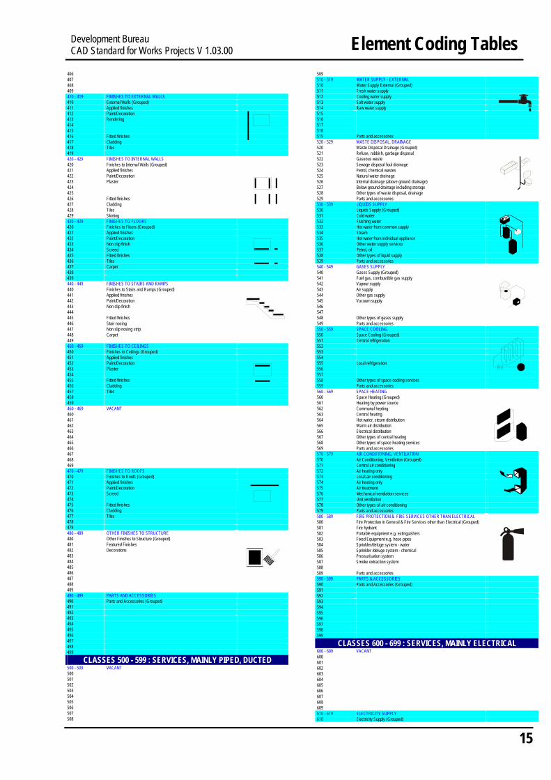
5.3 ELEMENT CODING TABLES

CLASSES 000 - 099 : GENERAL CLASSES 100 - 199 : GROUND, SUB-STRUCTURE
000 - 009 VACANT 100 - 109 VACANT 000 100 001 101 002 102 003 103 004 104 005 105 006 106 007 107 008 108 009 109 010 - 019 TITLES AND FRAMES 110 - 119 GROUND 010 011 012 013 014 015 016 017 018 019
Titles and Frames (Grouped) Frame Drawing Number Drawing Title Drawing creation information QA data e.g. automatic time/date/filename ref. Scale Drafting Body Copyright
110 111 112 113 114 115 116 117 118 119
Ground (Grouped) Ground relief Geological boundaries and features Ground composition Ground water Instrumentation Ground Samples e.g. Boreholes/trialpits Settlement Geological Contours/Isopachs Parts and accessories
020 - 029 GRIDS 120 - 129 EARTHWORKS 020 021 022 023 024 025 026 027
Grids (Grouped) National grid National grid text Site grid Site grid text Building / structure grid Building / structure grid text Geodetic Datumn
120 121 122 123 124 125 126 127
Earthworks (Grouped) Ground profiling Ground treatment Dredging Filling Slopes Berm Trench
028 029
Setting Out Lines 128 129
Reclamation Parts and accessories
030 - 039 DIMENSIONS 130 - 139 FLOOR BEDS 030 031 032
Dimensions (Grouped) Dimensions Plan levels
130 131 132
Floor Beds (Grouped) Hard surfaces e.g. ground floors
033 034 035
Chainage Setting out tables Coordinates
133 134 135
Soft surfaces e.g. planted, unplanted beds
036 136 Ground underwater e.g. pools 037 137 038 138 Other types of floor beds 039 139 Parts and accessories 040 - 049 040 041
TEXT (XXX1 ENGLISH, XXX2 CHINESE) Text (Grouped) Titles
140 - 149 140 141
TUNNELS Tunnels (Grouped) Tunnel walls
042 Sizes 142 Tunnel lining 043 044
Descriptions Notes
143 144
Portals Cross-passages
045 Schedules 145 Emergency passage 046 047
Legends 146 147
Shafts Adits
048 049 050 - 059
Reinforcement call-ups Steelwork call-ups
GENERAL SYMBOLS
148 149 150 - 159
Parts and accessories VACANT
050 051 052
General Symbols (Grouped) North point Section, detail, elevation marks
150 151 152
053 054
Match lines / cut lines Scale bars
153 154
055 Key Plan 155 056 156 057 157 058 158 059 159 060 - 069 HATCHING 160 - 169 RETAINING WALLS, FOUNDATIONS 060 Hatching (Grouped) 160 Retaining Walls, Foundations (Grouped) 061 Hatching 161 062 Patterning 162 Retaining walls 063 Fill tones 163 Water retaining elements e.g. dams, caissons 064 Highlighting 164 Foundations not piled 065 165 066 166 067 167 068 168 Other types of retaining foundation elements 069 169 Parts and accessories 070 - 079 REVISIONING 170 - 179 PILE FOUNDATIONS 070 Revisioning (Grouped) 170 Pile Foundations (Grouped) 071 Revision clouds and marks 171 Sheet piling 072 Revision box information 172 Replacement, in-situ formed pile foundations 073 173 Displacement, pre-formed formed pile foundations 074 174 Small displacement 075 175 076 176 077 177 078 178 Other types of pile foundations 079 179 Parts and accessories 080 - 089 TEMPORARY INFORMATION 180 - 189 OTHER SUBSTRUCTURE ELEMENTS 080 Temporary Information (Grouped) 180 Other Substructure Elements (Grouped) 081 082
Construction lines 181 182
Underground Valve and Meter Chambers
083 183 084 184 Thrust Blocks 085 Red-lining 185 086 186 087 187 088 188 089 189 090 - 099 VACANT 190 - 199 PARTS & ACCESSORIES 090 190 Parts and Accessories (Grouped) 091 191 Blinding/ Screed 092 192 Waterproofing/Damp proofing 093 193 Insulation 094 194 Back fill 095 195 Formwork 096 196 Falsework/Scaffolding 097 197 Reinforcement 098 198 Mesh 099 199
Development Bureau CAD Standard for Works Projects V 1.03.00 Element Coding Tables
13

CLASSES 200 - 299 : STRUCTURE PRIMARY ELEMENTS, 302303
200 - 209 VACANT 304 200 305 201 306 202 307 203 308 204 309 205 206 207
310 - 319 310 311
SECONDARY ELEMENTS TO WALLS, Secondary Elements to Ext. Walls (Grouped)
208 312 209 210 - 219 210 211
EXTERNAL WALLS
External Walls (Grouped) Loadbearing walls including cavity
313 314 315 316
Window/Door openings & parts to fill them Window openings and windows Doorways, entrances, exits and doors
212 213 214 215 216 217 218 219 220 - 229 220 221 222 223 224 225 226 227 228 229 230 - 239 230 231 232 233 234 235 236 237 238 239 240 - 249 240 241 242 243 244 245 246 247 248 249 250 - 259 250 251
Non-loadbearing walls Curtain walls Framing and cladding walls Other types of walls Parts and accessories
INTERNAL WALLS, PARTITIONS Internal Walls, Partitions (Grouped) Loadbearing internal walls
Non-loadbearing internal walls Baffle walls
Framing and cladding
Other types of internal walls Parts and accessories
FLOORS, GALLERIES Floors, Galleries (Grouped) Monolithic, slab floors Assembled, composite floors Galleries, balconies Other types of floors Parts and accessories STAIRS AND RAMPS Stairs and Ramps (Grouped) Straight stairs
Dog leg stairs Curved stairs Other types of stairs e.g. open well, escape Ladders, step irons, sliding poles Ramps Other types of vertical circulation Parts and accessories
VACANT
317 318 319 320 - 329 320 321 322 323 324 325 326 327 328 329 330 - 339 330 331 332 333 334 335 336 337 338 339 340 - 349 340 341 342 343 344 345 346 347 348 349 350 - 359 350 351 352 353 354 355 356
Hatch openings and hatches to fill them Others e.g. barred, louvred openings Parts and accessories SECONDARY ELEMENTS TO INTERNAL WALLS Secondary Elements to Internal Walls (Grouped)
Window/Door openings & parts to fill them Window openings and windows Doorways, room divider openings
Hatch openings, service voids Others e.g. barred openings Parts and accessories SECONDARY ELEMENTS TO FLOORS Secondary Elements to Floors (Grouped) Secondary suspended floors Secondary floor beds Plinths Floor openings e.g. trap doorways Others e.g. barred openings Parts and accessories SECONDARY ELEMENTS TO STAIRS & RAMPS Secondary Elements to Stairs & Ramps (Grouped) Balustrades Handrails Guide rails
Parts and accessories SUSPENDED CEILINGS Suspended Ceilings (Grouped) Jointless suspended ceilings Louvred suspended ceilings Ceiling openings and parts to fill them
252 357 253 254
358 359
Others e.g. ceiling walkways Parts and accessories
255 360 - 369 VACANT 256 360 257 361 258 362 259 363 260 - 269 VACANT 364 260 365 261 366 262 367 263 368 264 265 266 267 268 269 270 - 279 270 271 272 273 274 275 276 277 278 279 280 - 289 280 281 282 283 284 285 286 287 288 289 290 - 299 290 291 292 293 294 295 296
ROOFS Roofs (Grouped) Flat roof Pitched roof Folded plate roofs Other roofs by form e.g. dome, spires, cylindrical Roofs by structure e.g. arch, vaulted, suspended Cantilevered roofs, canopies Other types of roofs e.g. gabled, retractable Parts and accessories
BUILDING FRAMES, OTHER PRIM. ELEMENTS Building Frames, other Primary Elements (Grouped)
Column and beam frames Column and slab frames
Column and cable frames Space frames as building frames Other building frames e.g. pin-jointed Other types of primary elements e.g. shafts, chimneys Parts and accessories PARTS & ACCESSORIES Parts and Accessories (Grouped) Reinforcement
Steelwork Cables/Post tensioned cables/Prestressed cables Connection details Fixing details Joint details
369 370 - 379 370 371 372 373 374 375 376 377 378 379 380 - 389 380 381 382 383 384 385 386 387 388 389 390 - 399 390 391 392 393 394 395 396 397 398 399
SECONDARY ELEMENTS TO ROOFS Secondary Elements to Roofs (Grouped) Window/door openings & parts to fill them Window openings e.g. roof lights, sky lights Doorways e.g. trap door, access trap Roof eaves, parapets and balustrades Others e.g. walkways Parts and accessories OTHER SECONDARY ELEMENTS Other Secondary Elements (Grouped) Reinforcement Steelwork Louvers Connection details Fixing details Joint details
PARTS & ACCESSORIES Parts and Accessories (Grouped)
CLASSES 400 - 499 : FINISHES TO STRUCTURE 297 Bearings 400 - 409 VACANT 298 400 299 401
300 - 309 300 301
CLASSES 300 - 399 : SECONDARY ELEMENTS VACANT
402 403 404 405
14
Development BureauElement Coding Tables CAD Standard for Works Projects V 1.03.00
406
407 509 510 - 519 WATER SUPPLY - EXTERNAL 510 511 512 513 Salt water supply 514
408 Water Supply External (Grouped) 409 Fresh water supply 410 - 419 FINISHES TO EXTERNAL WALLS 410 External Walls (Grouped)
Cooling water supply
411 Applied finishes 412 Paint/Decoration 413 Rendering 414 415
Raw water supply 515 516 517 518
416 Fitted finishes 519 Parts and accessories 520 - 529 520 521
417 Cladding WASTE DISPOSAL, DRAINAGE 418 Tiles Waste Disposal Drainage (Grouped) 419 Refuse, rubbish, garbage disposal 420 - 429 FINISHES TO INTERNAL WALLS 522 Gaseous waste
523 524 525 526
420 Finishes to Internal Walls (Grouped) Sewage disposal foul drainage 421 Applied finishes Petrol, chemical wastes 422 Paint/Decoration 423 Plaster 424 425
Natural water drainage Internal drainage (above ground drainage)
527 Below ground drainage including storage 528 Other types of waste disposal, drainage
426 Fitted finishes Parts and accessories 427 Cladding
529 530 - 539 LIQUIDS SUPPLY 530 531 532
428 Tiles Liquids Supply (Grouped) 429 Skirting Cold water 430 - 439 FINISHES TO FLOORS Flushing water 430 Finishes to Floors (Grouped) 533 Hot water from common supply
534 535 536 537 538 539 540 - 549
431 Applied finishes Steam
432 Paint/Decoration 433 Non slip finish 434 Screed 435 Fitted finishes 436 Tiles
Hot water from individual appliance Other water supply services Petrol, oil Other types of liquid supply Parts and accessories GASES SUPPLY
540 Gases Supply (Grouped) 541 Fuel gas, combustible gas supply 542 Vapour supply 543 Air supply 544 Other gas supply 545 Vacuum supply 546 547 548 Other types of gases supply
437 Carpet 438 439 440 - 449 FINISHES TO STAIRS AND RAMPS 440 Finishes to Stairs and Ramps (Grouped) 441 Applied finishes 442 Paint/Decoration 443 Non slip finish 444 445 Fitted finishes 446 Stair nosing 549 Parts and accessories 447 Non slip nosing strip 550 - 559 SPACE COOLING
550 551 552 553
448 Carpet Space Cooling (Grouped) 449 Central refrigeration 450 - 459 FINISHES TO CEILINGS 450 Finishes to Ceilings (Grouped) 451 Applied finishes 554
555 556 557 558
452 Paint/Decoration 453 Plaster
Local refrigeration
454 455 Fitted finishes
Other types of space cooling services
456 Cladding 559 Parts and accessories 560 - 569 560 561 562
457 Tiles SPACE HEATING 458 Space Heating (Grouped) 459 Heating by power source 460 - 469 VACANT Communal heating 460 563 Central heating
564 565 566 567
461 Hot water, steam distribution 462 Warm air distribution 463 Electrical distribution 464 Other types of central heating 465 568 Other types of space heating services
569 570 - 579 570 571
466 Parts and accessories 467 AIR CONDITIONING, VENTILATION 468 Air Conditioning, Ventilation (Grouped) 469 Central air conditioning 470 - 479 FINISHES TO ROOFS 572 Air heating only
573 574 575 576 577
470 Finishes to Roofs (Grouped) Local air conditioning 471 Applied finishes Air heating only 472 Paint/Decoration 473 Screed
Air treatment Mechanical ventilation services
474 Unit ventilation 578 Other types of air conditioning 579
475 Fitted finishes 476 Cladding Parts and accessories 477 Tiles 580 - 589 FIRE PROTECTION & FIRE SERVICES OTHER THAN ELECTRICAL
580 581 582 583
478 Fire Protection in General & Fire Services other than Electrical (Grouped) 479 Fire hydrant 480 - 489 OTHER FINISHES TO STRUCTURE Portable equipment e.g. extinguishers 480 Other Finishes to Structure (Grouped) Fixed Equipment e.g. hose pipes 481 Featured Finishes 584 Sprinkler/deluge system - water
585 586 587 588
482 Decorations 483 484
Sprinkler /deluge system - chemical Pressurisation system Smoke extraction system
485
486 589 Parts and accessories 590 - 599 487 PARTS & ACCESSORIES
488 Parts and Accessories (Grouped) 489 490 - 499 PARTS AND ACCESSORIES 490 Parts and Accessories (Grouped) 491 492 493 494 495 496 497 498
590 591 592 593 594 595 596 597 598 599
CL600 - 609 600 UCTED 601 602 603 604 605 606 607 608 609
499 ASSES 600 - 699 : SERVICES, MAINLY ELECTRICAL
VACANT
CLASSES 500 - 599 : SERVICES, MAINLY PIPED, D500 - 509 VACANT 500 501 502 503 504 505 506
507 610 - 619 ELECTRICITY SUPPLY 610 508 Electricity Supply (Grouped)
Development Bureau CAD Standard for Works Projects V 1.03.00 Element Coding Tables
15

611 Radial distribution 612 Ring main distribution 613 Rising main distribution 614 615 616 Public mains supply 617 Privately generated supply 618 Other types of electrical supply services 619 Parts and accessories 620 - 629 POWER 620 Power (Grouped) 621 High voltage system (>1,000V rms) 622 Low voltage system (50 - 1,000V rms) 623 Extra-low voltage system (<50V rms) 624 625 Uninterruptible power supply 626 Battery power systems 627 Power subcircuit 628 Power trunking/conduit 629 Parts and accessories 630 - 639 LIGHTING 630 Lighting (Grouped) 631 General lighting 632 Local lighting 633 Emergency lighting 634 Street lighting 635 Airfield lighting 636 Floodlighting 637 Waterproof lighting 638 Other types of lighting services 639 Parts and accessories 640 - 649 COMMUNICATIONS 640 Communications (Grouped) 641 Visual including audio-visual 642 CCTV 643 Audio 644 Signals other than visual or audio 645 Synchronous clocks 646 SCADA 647 Signalling 648 Other types of communications services 649 Parts and accessories 650 - 659 VACANT 650 651 652 653 654 655 656 657 658 659 660 - 669 TRANSPORT 660 Transport (Grouped) 661 Lifts 662 Other types of internal lifts, hoists 663 Travelling cradles 664 Escalators 665 Conveyors/Travelators 666 Cable car, Gondola, Chair lift 667 Cranes 668 Other types of transport services 669 Parts and accessories 670 - 679 FIRE SERVICES ELECTRICAL 670 Fire Services Electrical (Grouped) 671 Audio/Visual fire alert system 672 Automatic fire detection and alarm system 673 Automatic heat detection and alarm system 674 Automatic smoke detection and alarm system 675 Manual fire alert system 676 Automatic leakage detection and alarm system 677 678 679 680 - 689 SECURITY, CONTROL, OTHER SERVICES 680 Security, Control, Other Services (Grouped) 681 682 Security services 683 684 685 686 Other security protection services 687 Control services - proocess/monitoring 688 Other types of security, control services 689 Parts and accessories 690 - 699 PARTS & ACCESSORIES 690 Parts and Accessories (Grouped) 691 692 693 Earthing Protection 694 Lightning protection 695 696 697 698 699
CLASSES 700 - 799 : FITTINGS, FURNITURE AND EQUIPMENT 700 - 709 VACANT 700 701 702 703 704 705 706 707 708 709 710 – 719 CIRCULATION FFE 710 Circulation FFE (Grouped) 711 Signs, symbols 712 Display fittings 713 Access fittings
714 Bollard/Cone/Barrier 715 Turnstiles 716 Flag 717 718 Other types of circulation fittings 719 Parts and accessories 720 - 729 REST, WORK FFE 720 Rest, Work FFE (Grouped) 721 Rest fittings 722 Fittings for relaxation 723 Work fittings 724 725 726 Benches, tables, seating, chairs 727 728 Other types of rest, work fittings 729 Parts and accessories 730 - 739 CULINARY FFE 730 Culinary FFE (Grouped) 731 Culinary work fittings 732 Sink, disposal units, washing up machines 733 734 Culinary processing, cooking fittings 735 Culinary storage fittings 736 737 Bar/Food counters, dining tables, seating 738 Other types of culinary, catering fittings 739 Parts and accessories 740 - 749 SANITARY FFE 740 Sanitary FFE (Grouped) 741 Sanitary suites 742 Washing fittings 743 Drying fittings 744 Disposal fittings 745 746 747 Supply fittings 748 Other types of sanitary, hygiene fittings 749 Parts and accessories 750 - 759 CLEANING FFE 750 Cleaning FFE (Grouped) 751 Washing fittings 752 753 Drying fittings 754 Pressing, Ironing fittings 755 756 757 758 Other types of cleaning, maintenance fittings 759 Parts and accessories 760 - 769 STORAGE, SCREENING FFE 760 Storage, Screening FFE (Grouped) 761 Composite storage fittings 762 Cupboards fittings 763 Drawers fittings 764 Shelving, racking fittings 765 Suspended storage fittings 766 Storage fittings with additional facility 767 Screening fittings 768 Other types of storage, screening fittings 769 Parts and accessories 770 - 779 SPECIAL ACTIVITY FFE 770 Special Activity FFE (Grouped) 771 Gymnasia/physical training facilities 772 Fighting sports facilities 773 One-to-one sports facilities e.g. squash 774 Bowling alleys 775 Athletics facilities 776 Racing facilities 777 Team ball games facilities 778 Equestrian facilities 779 Air sports facilities 780 - 789 OTHER FFE 780 Other FFE (Grouped) 781 782 783 Soft furnishings including upholstery 784 785 786 Works of art 787 788 789 790 - 799 PARTS AND ACCESSORIES 790 Parts and Accessories (Grouped) 791 792 Waste/Litter/Rubbish Bin 793 794 795 796 797 798 799
CLASSES 800 - 899 : TRANSPORT INFRASTRUCTURE 800 - 809 GROUND SURVEY 800 Ground Survey (Grouped) 801 Survey control 802 Elevation Contours 803 Spot levels 804 Artificial and Building Features 805 Relief and Hydrographic Features 806 Road and Street Features 807 Utilities Features 808 Military Cable 809 810 - 819 HIGHWAYS 810 Highways (Grouped) 811 Centre-lines 812 Setting out lines 813 Carriageway edges 814 Shoulders 815 Verges 816 Footpaths
16
Development BureauElement Coding Tables CAD Standard for Works Projects V 1.03.00

817 Cycle-tracks 908 818 Paved area 909 Parts and accessories 819 Parts and accessories 910 - 919 BOUNDARIES & ENCLOSURES 820 - 829 STREET FURNITURE 910 Boundaries & Enclosures (Grouped) 820 Street Furniture (Grouped) 911 Gazettal limits 821 822 823 824
Safety features / Railing / Barriers Weigh bridge Toll gate Speed humps
912 913 914 915
Planning boundaries Lot/Land allocation boundaries Site boundaries Works areas
825 Vehicle stops 916 Hoardings / fences / gates 826 917 Reserves 827 828
918 919
Swept paths / kinematic envelopes Parts and accessories
829 Parts and accessories 920 - 929 SURFACE WATER DRAINAGE 830 - 839 TRAFFIC AIDS & MARKINGS 920 Surface Water Drainage (Grouped) 830 Traffic Aids & Markings (Grouped) 921 River/Stream/Ditch 831 832 833 834 835 836
Traffic signs Markings Directional signs Traffic signals and equipment Cats eyes/Reflective studs Traffic Bollards
922 923 924 925 926 927
Culvert/Channel/Catchwater/Nullah Aqueduct Pipe Drain Manhole Catchpit
837 928 Pump 838 929 Parts and accessories 839 Parts and accessories 930 - 939 SEWERAGE 840 - 849 RAILWAYS 930 Sewerage (Grouped) 840 Railways (Grouped) 931 Pipe 841 Centre-lines 932 Manhole 842 843
Setting out lines Trackwork
933 934
Sewer Sewerage tank/Septic tank/Cesspools
844 Trackform 935 Outfall 845 Tramways 936 Sewage treatment plant 846 937 847 938 848 Safety features / Railing / Barriers 939 Parts and accessories 849 Parts and accessories 940 - 949 DUCTING (EXTERNAL) 850 - 859 BRIDGES 940 Ducting (Grouped) 850 Bridges (Grouped) 941 Ducts 851 Abutment 942 Access chambers 852 Anchor Block 943 Protective surround 853 Column 944 854 Pier 945 855 Tower 946 856 Deck 947 857 Parapet 948 858 Cable Support Systems 949 859 Parts and accessories 950 - 959 MARINE WORKS 860 - 869 GROUND SURFACE - AIRFIELDS 950 Marine Works (Grouped) 860 Ground Surface - Airfields (Grouped) 951 Bathymetric survey 861 Centre-lines, setting out lines 952 Seabed contours 862 Pavement edges 953 Breakwater 863 Shoulders 954 Dolphin 864 Pavement jointing 955 Floating jetty 865 956 Seawalls 866 957 Moorings / buoys 867 958 Fendering 868 959 Parts and accessories 869 Parts and accessories 960 - 969 MARINE FURNITURE 870 - 879 VACANT 960 Marine Furniture (Grouped) 870 961 Notice board 871 962 Bollard 872 963 Handrail 873 964 Pillar box 874 965 Refuse containment room 875 966 Seawall block 876 967 Wave detector block 877 968 Tetrapod 878 969 879 970 - 979 STRUCTURES IN EXTERNAL WORKS 880 - 889 VACANT 970 Structures in External Works (Grouped) 880 971 Building outlines 881 882
972 973
Underground building outlines Pylons/Antenna/Masts
883 974 884 975 Utility connection points 885 976 886 977 887 978 Noise barriers 888 979 Parts and accessories 889 980 - 989 LANDSCAPING 890 - 899 TRANSPORT INFR. PARTS & ACCESSORIES 980 Landscaping (Grouped) 890 Parts and Accessories (Grouped) 981 Hard landscaping 891 Reinforcement 982 Soft landscaping 892 Steelwork 983 Features eg. Sculptures / water features 893 Post tensioned cables/Prestressed cables 984 Landscaping structures e.g. shade structure 894 Connection details 985 895 Fixing details 986 896 Joint details 987 Sports facilities 897 Bearings 988 898 989 899 990 - 999 EXTERNAL WORKS PARTS & ACCESSORIES
CLASSES 900 - 999 : EXTERNAL WORKS 990 991
Parts and Accessories (Grouped)
900 - 909 SITE PREPARATION 992 900 Site Preparation (Grouped) 993 901 Clearing/demolition 994 902 Sign Board 995 903 996 904 905 906 907
997 998 999
Development Bureau CAD Standard for Works Projects V 1.03.00 Element Coding Tables
17

Development Bureau CAD Standard for Works Projects V 1.03.00
This is a blank page
18

This section addresses:
• Line thicknesses;
• the assignment of line thicknesses;
• the use of LTSCALE and PSLTSCALE in AutoCAD; and
• symbols and special line-styles
AutoCAD
6.2 ASSIGNMENT OF LINE THICKNESSES
Development Bureau CAD Standard for Works Projects V 1.03.00 Lines
6 LINES
6.1 LINE THICKNESSES
Line Thicknesses to be used in AutoCAD and Microstation
0.13mm 0.18mm 0.25mm 0.35mm 0.50mm 0.70mm 1.00mm 2.00mm
Microstation
Line thickness shall be assigned by weight and not by colour.
The CSWP line thickness can be selected from the standard AutoCAD line weight settings dialogue box.
Only the CSWP line thickness values are to be selected, the ‘default’ line weight is not to be used.
Line thickness shall be assigned by weight and not by colour.
Weight 0 = 0.13mm Weight 1 = 0.18mm Weight 2 = 0.25mm Weight 3 = 0.35mm Weight 4 = 0.50mm Weight 5 = 0.70mm Weight 6 = 1.00mm Weight 7 = 2.00mm
19
Development BureauLines CAD Standard for Works Projects V 1.03.00
6.3 AutoCAD LIN LIBRARY FILE
6.3.1 The default AutoCAD LIN LIBRARY file shall be ACADISO.lin
6.4 AutoCAD LTSCALE AND PSLTSCALE SETTING
6.4.1 The LTSCALE factor in drawing files shall be the 1 x the Plot Scale
6.4.2 The LTSCALE factor in model files shall be the AutoCAD default value.
6.4.3 Note. If it is required to plot directly from a model file, then the LTSCALE factor should temporarily be set to 1 x the Plot Scale.
6.4.4 PSLTSCALE shall be set to 1.
6.5 SYMBOLS AND CUSTOM LINESTYLES
6.5.1 The naming of symbols and custom line-styles is described in Sections 11 and 12.
6.5.2 Symbol and custom line-style libraries are available from www.devb-wb.gov.hk/cswp .
20

AutoCAD
Text Height (mm)
Development Bureau CAD Standard for Works Projects V 1.03.00 Text
7 TEXT
This section addresses:
• English Text:
• Font types
• Text sizes
• Width factor
• Line spacing
• Chinese Text:
• Font type and specification
• Text sizes
• Width factor
• Line spacing
• Special Characters
7.1 ENGLISH TEXT
7.1.1 FONTS
Microstation
Font Romans Engineering
Font No in Microstation
N/A Font No. 3
Style Name inAutoCAD
STANDARD N/A
7.1.2 TEXT SIZES
Thickness (mm) 2.00mm 0.25mm 2.50mm 0.25mm 3.50mm 0.35mm 5.00mm 0.50mm 7.00mm 0.70mm 10.00mm 1.00mm 20.00mm 2.00mm
7.1.3 WIDTH FACTOR
A width factor of 0.8 x Text Height shall be used
21

AutoCAD
AutoCAD
AutoCAD
Development BureauText CAD Standard for Works Projects V 1.03.00
7.1.4 LINE SPACING
Microstation
Line spacing between Multi-line text shall be set using the single (1.0x) setting.
Line spacing between Multi-line text shall be 0.5 x the maximum height of text in the line.
7.2 CHINESE TEXT
7.2.1 FONTS
Chinese Text Font files are not included within the CSWP downloadable resource files for licensing reasons. Users shall obtain font files that meet the following specification:
Microstation
Font Styles Ming Light (細明體)
Ming Medium (中明體)
Ming Bold (粗明體)
Character Set Each font shall contain all the standard BIG5 traditional Chinese characters (13,500 characters) and also all the Hong Kong Supplementary Character Set (HKSCS-2001 standard) as posted on the web site: http://www.info.gov.hk/digital21/eng/hkscs/download.html
Internal Coding Big-5
File Type A single true type font file for each of the three font styles
A single true type font file for each of the three font styles converted to a single Microstation .RSC file.
In implementing Chinese fonts the following shall be applied:
Microstation
Font No. to be allocated in Microstation N/A
Ming Light Font No. 195
Ming Medium Font No. 196
Ming Bold Font No. 197
Style Names to begiven in AutoCAD
Style names for the three Chinese fonts shall be defined as follows, in English (language) within the AutoCAD file, irrespective of the language of the operating system or of the AutoCAD system.
Ming Light MINGL
Ming Medium MINGM
Ming Bold MINGB
N/A
22

AutoCAD
Development Bureau CAD Standard for Works Projects V 1.03.00 Text
7.2.2 TEXT HEIGHTS
Text Height (mm) 3.00mm 3.75mm 5.25mm 7.50mm 10.50mm 15.00mm 30.00mm
7.2.3 WIDTH FACTOR
A width factor of 1.0 x Text Height shall be used.
7.2.4 LINE SPACING
Microstation
Line spacing between Multi-line text shall be set using the single (1.0x) setting.
Line spacing between Multi-line text shall be 0.5 x the maximum height of text in the line.
7.3 TEXT ON LANDS DEPARTMENT MAPPING
7.3.1 To avoid confusion, the CSWP font specifications are not applicable to the maps produced by Lands Department.
23

Special Characters in AutoCAD
7.4
Development BureauText CAD Standard for Works Projects V 1.03.00
SPECIAL CHARACTERS
Special Characters in Microstation
AutoCAD users shall use only the special characters available from the default ROMANS character map.
The following ‘key-in’ special characters can also be used: %%c for diameter symbol %%d for degrees symbol %%o for placing lines above text %%p for plus/minus symbol %%u for placing lines under text
Microstation users shall use only the special characters available from the default Font 3 (Engineering)
24

AutoCAD
8
Development Bureau CAD Standard for Works Projects V 1.03.00 Colours & Scales
COLOURS
Microstation
The default AutoCAD colour table shall be used.
Only colours 250 - 254 shall be used as grey scales.
The following five grey scales shall be added to the default Microstation colour table. Only colours 250 -254 shall be used as grey scales. (This will enable the AutoCAD and Microstation grey scales to be matched.)
The RGB definition of the grey scales 250 - 254 are as follows:
Colour R G B
250 176 176 176
251 200 200 200
252 220 220 220
253 240 240 240
254 250 250 250
9 SCALES
9.1 SCALE OF ORIGINAL CAD DATA
All elements shall be drawn at scale 1:1 in the CAD files.
The CAD data can then be plotted at different scales for different purposes using the CAD packages’ plotting options.
9.2 GUIDELINES FOR PLOTTED SCALES
• Scales should be whole numbers
• The number of scales on any one drawing should be kept to a minimum
• The scale shall be clearly identified under the title of each portion of the drawing
• The scale chosen shall be large enough to permit clear and easy interpretation of the information
• Where different scales are used for horizontal and vertical dimensions, such as on profiles, each scale shall be clearly indicated.
25

Development Bureau CAD Standard for Works Projects V 1.03.00
This is a blank page
26

Format
10 PAPER SIZES
Development Bureau CAD Standard for Works Projects V 1.03.00 Paper Sizes
PAPER SIZES TO BE USED FOR PLOTTED WORKING DRAWINGS
Size (mm)
A0
A1
A2
A3
A4
*B0
B1
841x1189
594x841
420x594
297x420
210x297
1000x1414
707x1000
* The use of B0 should be kept to a minimum as it exceeds the maximum plot size of most plotters.
27

Development Bureau CAD Standard for Works Projects V 1.03.00
This is a blank page
28

AutoCAD
Development Bureau CAD Standard for Works Projects V 1.03.00 Symbol Libraries
11 SYMBOL LIBRARIES
Note: Symbols will only be created and updated under the direction of the CSWP Working Group. The symbol libraries can be downloaded from the Development Bureau web site www.devb-wb.gov.hk/cswp
Folder, File and Symbol Naming for CSWP Symbol Libraries
Microstation
The CSWP\SYMBOLS folder will have 10 sub- The CSWP\SYMBOLS folder will have 10 sub-folders named after the ten main divisions of the folders named after the ten main divisions of the CSWP Element Coding table: CSWP Element Coding table: \000 \000 \100 \100 \200 \200 \300 \300 \400 \400 \500 \500 \600 \600 \700 \700 \800 \800 \900 \900 These folders will contain up to ten sub-folders. The These folders will contain up to ten cell libraries. sub-folders will be named by: The cell libraries will be named by:
CSWP Element Main Class, e.g. CSWP Element Main Class, e.g. \800\800 \800\800.CEL \800\810 \800\810.CEL \800\820 \800\820.CEL \800\830 \800\830.CEL \800\840 \800\840.CEL \800\850 \800\850.CEL \800\860 \800\860.CEL \800\890 \800\890.CEL
The symbols will then be held in the Main Class sub- The symbols will then be held in the cell libraries and folder as individual .DWG files named with the named with the symbol name, e.g. symbol name, e.g.
NORTHP.DWG (North-point) NORTHP (North-point)
BHOLE.DWG (Bore-hole) BHOLE (Bore-hole)
TPIT.DWG (Trial Pit) TPIT (Trial-pit)
Symbol file names not to exceed 6 characters to Note that cell names cannot exceed 6 alphanumeric avoid truncation when transferred to Microstation. characters in Microstation.
29

Development Bureau CAD Standard for Works Projects V 1.03.00
This is a blank page
30

AutoCAD
Development Bureau CAD Standard for Works Projects V 1.03.00 Custom Line-style Libraries
12 CUSTOM LINE-STYLE LIBRARIES
Note: Custom line-styles will only be created and updated under the direction of the CSWP Working Group. The line-style libraries can be downloaded from the Development Bureau web site www.devb-wb.gov.hk/cswp
Folder, File and Line-style Naming for CSWP Resource Files
Microstation
The AutoCAD custom line styles will be held in LIN The Microstation custom line styles will be held in library files located in the CSWP\RESOURCES resource files located in the CSWP\RESOURCES directory. The LIN library files will be named and directory. The resource files will be named and categorised according to the 10 element divisions in categorised according to the 10 element divisions in the CSWP Element Codes: the CSWP Element Codes:
CSWP\RESOURCES\000.lin CSWP\RESOURCES\000.rsc
CSWP\RESOURCES\100.lin CSWP\RESOURCES\100.rsc
CSWP\RESOURCES\200.lin CSWP\RESOURCES\200.rsc
CSWP\RESOURCES\300.lin CSWP\RESOURCES\300.rsc
CSWP\RESOURCES\400.lin CSWP\RESOURCES\400.rsc
CSWP\RESOURCES\500.lin CSWP\RESOURCES\500.rsc
CSWP\RESOURCES\600.lin CSWP\RESOURCES\600.rsc
CSWP\RESOURCES\700.lin CSWP\RESOURCES\700.rsc
CSWP\RESOURCES\800.lin CSWP\RESOURCES\800.rsc
CSWP\RESOURCES\900.lin CSWP\RESOURCES\900.rsc
The line styles will be held in the .LIN library files The line styles will be held in the resource files and and given a name and a version number to allow for given a name and a version number to allow for future modification. future modification.
Examples of custom line style names common to AutoCAD and Microstation
Format: Name_Version, e.g.
EXGAS_00 Existing Gas Line (initial version)
EX11KV_01 Existing 11kv electricity line (first revision)
RM1107_02 Road marking style 1107 (second revision)
31

Development Bureau CAD Standard for Works Projects V 1.03.00
This is a blank page
32

Section CSWP Component Mandatory Requirement
Development Bureau CAD Standard for Works Projects V 1.03.00 Summary of Requirements
13 SUMMARY OF REQUIREMENTS
13.1 MANDATORY / USER CHOICE
The following table summarises those parts of the CSWP that are mandatory and those for which the users are required / free to make choices.
User Free to Choose
3
FOLD
ERS
CSWP Common Data Folders
Folder Structure and Naming -
Project Data Folders Folder Structure Top level folder name (to be agreed with Works Department) Division of model files into MODEL sub-folder Use of sub sub-folders for discipline split Use of REVISION folder
File Settings Settings Use of metres or millimetres units
Drawing Files Naming Format Drawing number and revision
4
FILE
S Model Files Naming Format
Agent Responsible Code from prescribed list
View from list
Status from list
Use of Project ID (min 1 max 8 characters)
File ID (min 4 max 8 characters)
5
LAYE
RS
Layer Naming Format
Agent Responsible Code from prescribed list
Element Code from list
Use of underscores to fill blank characters
User definable code
Element Coding First three digits from Element Coding Table provided
User is free to set the 4th digit, if required, or replace by underscore
6
LINE
S
Thicknesses
Assignment of Microstation line weight No. to thickness
Use of lines by weight in AutoCAD
AutoCAD LIN file
AutoCAD LTSCALE and PSLTSCALE settings
Custom Line-styles
Choose from prescribed range
Line weights prescribed to thicknesses
Prescribed
ACADISO.lin prescribed
Prescribed
Provided in library
Thickness to suit drawn elements
-
-
-
-
Appropriate line-style
33

Section CSWP Component Mandatory Requirement
Development BureauSummary of Requirements CAD Standard for Works Projects V 1.03.00
User Free to Choose
7 TEXT
English Text Font type
Prescribed range of sizes
Width factor
Line spacing
-
Choose appropriate size
-
-
Chinese Text Font styles, character set and internal coding specified
Prescribed range of sizes
Width factor
Line spacing
-
Choose appropriate size
-
-
Special Characters Special characters from specified fonts only
-
8
COLO
URS Colours CSWP Colour Table User is free to choose colours for
presentation / colour drawings
9
SCAL
ES
Scales All data to be drawn at 1:1 and scaled for plotting
Appropriate scales for plotting
10
PAPE
R SI
ZES Paper Sizes Standard sizes for working
drawings Appropriate size for drawings
11
SYMB
OLS
Symbol Libraries Symbol libraries provided and downloadable from www.devb-wb.gov.hk/cswp
Appropriate symbol.
If no appropriate symbol exists, Users shall use their own defined symbols with their descriptions shown in a legend and may propose these new symbols for the CSWP Working Group’s consideration via the web site
12
CUST
OM L
INE-
STYL
ES
Line-style Libraries Line-style Libraries provided and downloadable from www.devb-wb.gov.hk/cswp
Appropriate line-style.
If no appropriate line-style exists, Users shall use their own defined line-styles with their descriptions shown in a legend and may propose these new line-styles for the CSWP Working Group’s consideration via the web site
34

Development Bureau CAD Standard for Works Projects V 1.03.00 References
13.2 REFERENCES
The Agent Responsible Codes, Symbol Libraries and Line-style Resource files can be found on the Development Bureau web site www.devb-wb.gov.hk/cswp
35
Top Related