


Languages
Pages
Legal


Standard-Hubsäulen C6für OP-Tische, einbaufertig
Standard Lift Columns C6for Operating Tables, ready to fit

With more than 25 years of experience
in micro hydraulics we have acquired
not only national but also interational
fame as „the specialist“ in this field.
Due to continuous improvement and
development for patient positioning
(such as operating tables) we have
obtained a position as market leader.
In a close co-operation with
HOERBIGER Automatisierungstechnik,
HOERBIGER Micro Fluid is a
competent and effiecient partner for
the industry in niche markets.
Mit mehr als 25 Jahre Erfahrung im
Bereich der Mikrohydraulik haben wir
uns nicht nur national sondern auch
international den Ruf
“der Spezialist” in diesem Ressort
erwerben können.
Im Bereich Patientenlagerung
(wie z. B. OP-Tischen) haben wir durch
kontinuierlichen Ausbau und steter
Weiterentwicklung eine Markt-
führerposition eingenommen.
In enger Zusammenarbeit mit der
HOERBIGER Automatisierungstechnik
ist die HOERBIGER Micro Fluid ein
kompetenter und leistungsfähiger
Partner der Industrie in den Nischen-
märkten.
Ein modernes, aufstrebendesUnternehmen stellt sich vor:
A modern and growingcompany introduces itself:
2

Wir sind zertifiziert nach
DIN EN ISO 9001: 2000
EN ISO 13485: 2000
VDA 6, Teil 1
Wir verstehen uns als Partner zum
Kunden, um in gemeinsamer Zusam-
menarbeit erfolgreiche Lösungen zu
generieren.
Die HOERBIGER Micro Fluid GmbH in
Barbing beschäftigt 50 Mitarbeiter und
sieht sich als Partner und Vordenker
der Industrie im Bereich Automation,
Fahrzeugtechnik und Patientenlagerung
für Systemlösungen. HOERBIGER
weltweit beschäftigt mehr als 4300
Mitarbeiter.
We are audited according to:
DIN EN ISO 9001: 2000
EN ISO 13485: 2000
VDA 6, Teil 1
We understand ourself as partner for
the client, in order to realize together
successful solutions.
HOERBIGER Micro Fluid in Barbing
has 50 employees and does see itself
as partner and pioneer for the industry
for system solutions in the field of
automation, automotive engineering
and patient positioning.HOERBIGER
worldwide has more than 4300
employees.
3

Max. Patientengewicht,Kräfte, Momente
Max. Patient weight,Forces and Torques
Das Moment um die Trendelenburg-
achse wird erzeugt durch den
Patienten, die Lagerfläche und das
OP-Zubehör.
Zur Betrachtung des maximal
möglichen Patientengewichtes wird
eine übliche Gewichtsverteilung von
Patient, Lagerfläche und Zubehör
angenommen.
Weitere Annahmen:
- Keine Tischlängsverschiebung
- Trendelenburgzylinder kopfseitig
- Patient liegt mit Kopf am Ende der
Lagerfläche
- Patientengewicht 255 kg, Verteilung
lt. DIN EN 60601
Allgemeine Information zur
Patientenlagerung und deren Kraft-
verteilung
Torque at the Trendelenburg axis is
caused by the patient, the top plate
and the surgery equipment.
To consider the max. patient weight
possible, a normal weight distribution
of the patient, the top plate and the
accessories are assumed.
Additional suppositions:
- no slide movement of the table top
- Trendelenburg cylinder at the head
section
- patient head is situated at the end of
the head section
- patient weight 255 kg, distribution
according to DIN EN 60601
General information about patient
positioning and its weight
distribution
4
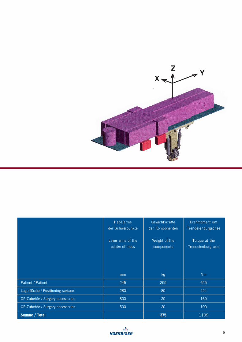
ZY
X
Hebelarme
der Schwerpunkte
Lever arms of the
centre of mass
Drehmoment um
Trendelenburgachse
Torque at the
Trendelenburg axis
Gewichtskräfte
der Komponenten
Weight of the
components
Patient / Patient
Summe / Total
OP-Zubehör / Surgery accessories
Lagerfläche / Positioning surface
OP-Zubehör / Surgery accessories
80
20
375
20
255
1109
100
160
224
625
280
800
500
245
mm kg Nm
5
From our product range of various
types of lift columns we present to you
the different versions of lift column
C6.
The basic version consists of 3 basic
movements (stroke, lateral, tilt), which
can be operated either manually
(description page 10) or electrically
(description page 12).
Three extra functions (for example leg,
back, foot lock) can be realized in
addition (description page 14).
The power supply has to be provided
by the manufacturer of the operating
table.
All versions are closed systems whose
function and tightness are tested and
ready to be installed in your operating
table.
6
Aus dem Produktspektrum mehrerer
Hubsäulenvarianten zeigen wir hier die
Hubsäule C6 in unterschiedlichen
Ausführungen.
Die Grundausführung besteht aus 3
Basisbewegungen ( Hub, Trend, Tilt )
die sowohl manuell (Beschreibung
Seite 10) als auch elektrisch
(Beschreibung Seite 12) betätigt
werden. Zusätzlich können drei weitere
Funktionen (zum Beispiel Bein,
Rücken, Fußfeststellung) realisiert
werden (Beschreibung Seite 14).
Die Spannungsversorgung muß durch
den OP-Tischhersteller zur Verfügung
gestellt werden.
Bei allen Ausführungen handelt es sich
um ein geschlossenes System das auf
Funktion und Dichtheit geprüft und für
den Einbau in Ihren OP-Tisch
vorbereitet ist.
Lift Column C6Hubsäule C6

7
3 Funktionen manuell betätigt3 functions manually operated
3 Funktionen elektrisch betätigt3 functions electrical operated

8
Abmaße
Breite 301 mm
Tiefe C6 manuell 240 mm
Tiefe C6 252 mm
elektrisch, 3 Bewegungen
Tiefe C6 273 mm
elektrisch, 6 Bewegungen
Höhe 579 mm
Gewicht ca. 40 kg
Bewegungen
Hub 360 mm
Trendelenburg ± 30°
Kantung ± 20°
Geschwindigkeit ca. 9 mm/s
(ohne Belastung!)
Kräfte (theoretisch)
Hub 5000 N
Nennbelastungen*
x-Achse 1100 Nm
y-Achse 250 Nm
z-Achse 500 Nm
* bei 4-facher Sicherheit
Umgebungstemperatur 15° . . . 35°C
Lagerungstemperatur -15° . . 60°C
Lift Column C6Hubsäule C6
Dimensions
width 301 mm
depth C6 manual 240 mm
depth C6 252 mm
electric, 3 movements
depth C6 273 mm
electric, 3 movements
height 579 mm
weight approx. 40 kg
Movements
stroke 360 mm
lateral ± 30°
tilt ± 20°
Speed approx. 9 mm/s
(without load!)
Forces (theoretically)
stroke 5000 N
Torque nominal*
x-axis 1100 Nm
y-axis 250 Nm
z-axis 500 Nm
* at a safety factor of 4
Ambient temperature 15° . . . 35°C
Storage temperature -15° . . 60°C

9
6 Funktionen elektrisch betätigt6 functions electrical operated

BeispielExample
Durch die Betätigung der Fußpumpe
(z. B. Betätigung über ein Pedal)
können die Bewegungen abgefahren
werden. Hierzu wird nur die Stellung
des Rotationsventils (5) in die ge-
wünschte Position gebracht. Jetzt
bewegt sich der Rahmen (2). Eine
Änderung der Bewegungsrichtung wird
über das Umsteuerventil (6) erreicht.
manuell, 3 Bewegungen
Lift Column C6
The movements can be activated by
operating the foot pump (e.g. by
pedal). The position of the rotary valve
(5) has to be put into the desired
position. The frame (2) moves. A
change of the movement direction is
achieved by the reversing valve (6).
10
Hubsäule C6manual, 3 movements
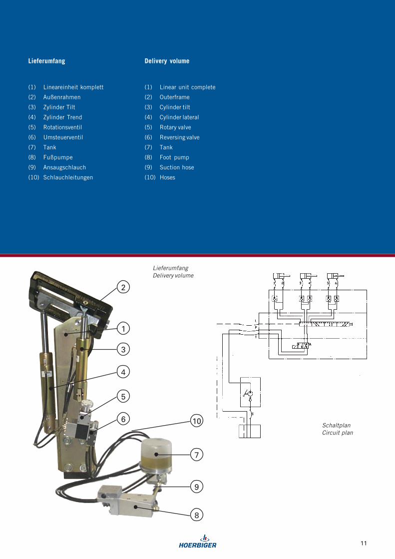
Lieferumfang Delivery volume
(1) Lineareinheit komplett
(2) Außenrahmen
(3) Zylinder Tilt
(4) Zylinder Trend
(5) Rotationsventil
(6) Umsteuerventil
(7) Tank
(8) Fußpumpe
(9) Ansaugschlauch
(10) Schlauchleitungen
(1) Linear unit complete
(2) Outerframe
(3) Cylinder tilt
(4) Cylinder lateral
(5) Rotary valve
(6) Reversing valve
(7) Tank
(8) Foot pump
(9) Suction hose
(10) Hoses
SchaltplanCircuit plan
11
10
8
6
5
4
3
9
7
2
1
LieferumfangDelivery volume

Die Spannungsversorgung 24 V DC
erfolgt extern über Akku (nicht im
Lieferumfang enthalten).
Nach deren Anschluß können durch
Drücken der Tasten am Handbedienteil
die gewünschten Bewegungen
abgefahren werden.
Hubsäule C6electric, 3 movements
The power supply 24 VDC is effected
externally by an akku (not included in
the delivery volume).
After the akku is connectrd the desired
movements can by activated by
pressing the buttons on the hand
panel.
elektrisch, 3 Bewegungen
Lift Column C6
Besonderheiten:
� das elektrische System schaltet
sich nach 30s aus, wenn keine
Taste am Handbedienteil betätigt
wird
� Anzeigen der Betriebszustände
durch die beiden LED´s
(Ready & Service)
Option:
� RTL-Funktion (Horizontale
Nullage)
Hydraulikaggregat:
Nennspannung 24 VDC
Stromaufnahme max. 15 A
Schutzart IP54
Betriebsdruck 140 bar
Elektronik:
EMV getestet EN60601-1-2:1993
(mit Verkleidung der Hubsäule aus
Edelstahl 2 mm)
Particularities:
� if no button is pressed on the
hand panel the electric system is
switched off after 30 s.
� Two LED displays
(Ready & Service) indicate the
operating states
Option:
� horizontal zero position
Hydraulic power unit:
Nominal voltage 24 VDC
Power consumption max. 15 A
Protection class IP54
Working pressure 140 bar
Electronic:
EMC tested according to EN60601-1-
2:1993 (case of the lift column in
stainless steel 2 mm)
12

(1) Lineareinheit komplett
(2) Außenrahmen
(3) Zylinder Tilt
(4) Zylinder Trend
(5) Aggregat A 08
(6) Elektronikplatine kompl. (MPC)
(7) Rotationsventil kompl.
(8) Handbedienteil inkl. Spiralkabel
(9) Kabelbaum
(10) Schlauchleitungen
(1) Linear unit complete.
(2) outer frame
(3) Cylinder tilt
(4) Cylinder lateral
(5) Power unit A 08
(6) Electronic board complete. (MPC)
(7) rotary valve complete
(8) hand panel incl. spiral cable
(9) cable harness
(10) hoses
2
9
8
7
3
4
5
10
6
1
LieferumfangDelivery volume
Handbedienteilmit 3 Funktionen
Hand panelwith 3 functions
Platz für Firmenlogo
space for company logo
SchaltplanCircuit plan
Lieferumfang Delivery volume
13
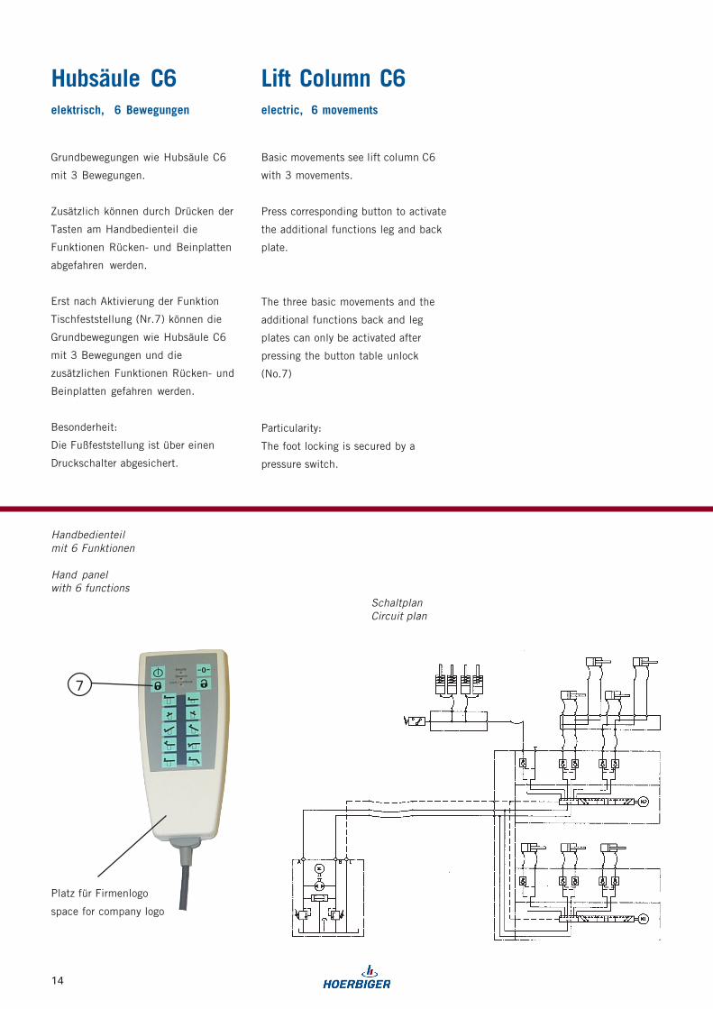
Grundbewegungen wie Hubsäule C6
mit 3 Bewegungen.
Zusätzlich können durch Drücken der
Tasten am Handbedienteil die
Funktionen Rücken- und Beinplatten
abgefahren werden.
Erst nach Aktivierung der Funktion
Tischfeststellung (Nr.7) können die
Grundbewegungen wie Hubsäule C6
mit 3 Bewegungen und die
zusätzlichen Funktionen Rücken- und
Beinplatten gefahren werden.
Besonderheit:
Die Fußfeststellung ist über einen
Druckschalter abgesichert.
Hubsäule C6elektrisch, 6 Bewegungen electric, 6 movements
Basic movements see lift column C6
with 3 movements.
Press corresponding button to activate
the additional functions leg and back
plate.
The three basic movements and the
additional functions back and leg
plates can only be activated after
pressing the button table unlock
(No.7)
Particularity:
The foot locking is secured by a
pressure switch.
7
Handbedienteilmit 6 Funktionen
Hand panelwith 6 functions
Platz für Firmenlogo
space for company logo
SchaltplanCircuit plan
Lift Column C6
14
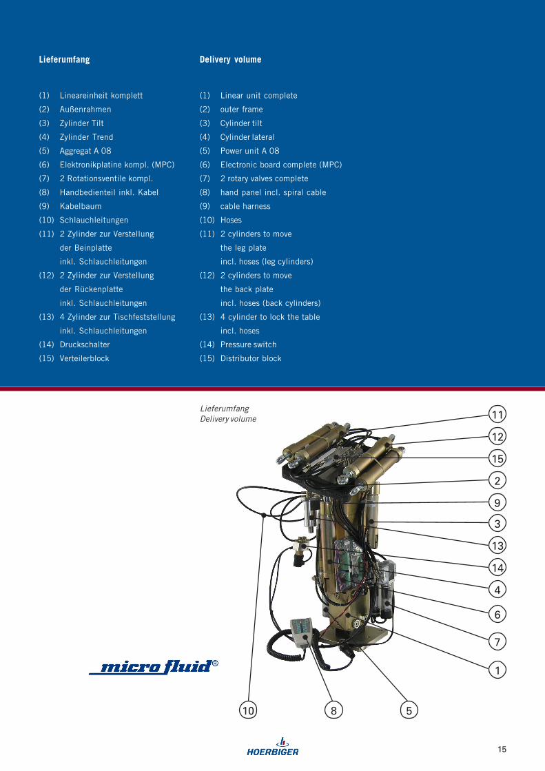
(1) Lineareinheit komplett
(2) Außenrahmen
(3) Zylinder Tilt
(4) Zylinder Trend
(5) Aggregat A 08
(6) Elektronikplatine kompl. (MPC)
(7) 2 Rotationsventile kompl.
(8) Handbedienteil inkl. Kabel
(9) Kabelbaum
(10) Schlauchleitungen
(11) 2 Zylinder zur Verstellung
der Beinplatte
inkl. Schlauchleitungen
(12) 2 Zylinder zur Verstellung
der Rückenplatte
inkl. Schlauchleitungen
(13) 4 Zylinder zur Tischfeststellung
inkl. Schlauchleitungen
(14) Druckschalter
(15) Verteilerblock
(1) Linear unit complete
(2) outer frame
(3) Cylinder tilt
(4) Cylinder lateral
(5) Power unit A 08
(6) Electronic board complete (MPC)
(7) 2 rotary valves complete
(8) hand panel incl. spiral cable
(9) cable harness
(10) Hoses
(11) 2 cylinders to move
the leg plate
incl. hoses (leg cylinders)
(12) 2 cylinders to move
the back plate
incl. hoses (back cylinders)
(13) 4 cylinder to lock the table
incl. hoses
(14) Pressure switch
(15) Distributor block
Lieferumfang Delivery volume
11
12
15
2
3
13
14
4
6
7
1
10 5
9
8
LieferumfangDelivery volume
15
HOERBIGER Micro Fluid GmbH
Borsigstraße 11
93092 Barbing
GERMANY
Tel. +49 (0)9401 785 - 0
Fax +49 (0)9401 785 - 50
E-mail [email protected]
www.hoerbiger-microfluid.com
907X1
005
Die hier gemachten Angaben sind
typische Werte; sie sind keine
zugesicherten Eigenschaften im
Rechtssinne.
Technische Änderungen und Irrtümer
vorbehalten.
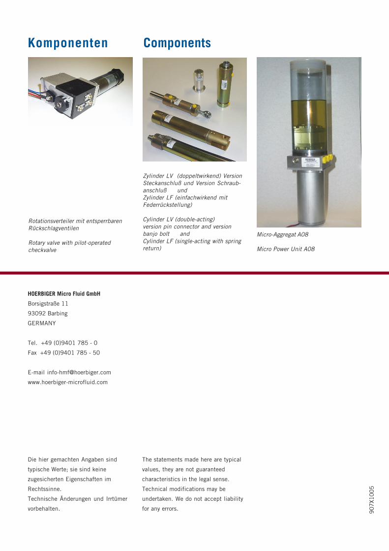
Komponenten
Zylinder LV (doppeltwirkend) VersionSteckanschluß und Version Schraub-anschluß undZylinder LF (einfachwirkend mitFederrückstellung)
Cylinder LV (double-acting)version pin connector and versionbanjo bolt andCylinder LF (single-acting with springreturn)
Micro-Aggregat A08
Micro Power Unit A08
Rotationsverteiler mit entsperrbarenRückschlagventilen
Rotary valve with pilot-operatedcheckvalve
Components
The statements made here are typical
values, they are not guaranteed
characteristics in the legal sense.
Technical modifications may be
undertaken. We do not accept liability
for any errors.
Top Related