


Languages
Pages
Legal

BY ORDER OF THE COMMANDER
AIR FORCE SPACE COMMAND
AIR FORCE SPACE COMMAND
MANUAL 91-710 VOLUME 2
13 JULY 2017
Safety
RANGE USER LAUNCH SAFETY
REQUIREMENTS MANUAL VOLUME
2, FLIGHT SAFETY REQUIREMENTS
COMPLIANCE WITH PUBLICATION IS MANDATORY
ACCESSIBILITY: Publication are forms are available for downloading or ordering on the
e-Publishing website at www.e-Publishing.af.mil.
RELEASABILITY: There are no releasability restrictions on this publication
OPR: HQ AFSPC/SEK
Supersedes: AFSPCMAN 91-710V2,
1 July 2004
Certified by: AFSPC/SEK
(Mr. Edward Rivera)
Pages: 98
This manual implements Department of Defense Directive (DoDD) 3100.10, Space Policy,
DoDD 3200.11, Major Range and Test Facility Base, DoDD 3230.3, Management and
Operation of the Major Range and Test Facility Base, DoDI 3200.18, DoD Support for
Commercial Space Launch Activities, Air Force Policy Directive (AFPD) 91-1, Nuclear
Weapons and Systems Surety, AFPD 91-2, Safety Programs, Air Force Instruction (AFI) 91-217,
Space Safety and Mishap Prevention Program, AFI 91-202, US Air Force Mishap Prevention
Program, Air Force Space Command (AFSPC) Sup.1, and the Memorandum of Agreement
between the Department of the Air Force and the Federal Aviation Administration (FAA) on
Safety for Space Transportation and Range Activities. This volume incorporates information
previously found in Eastern and Western Range 127-1, Chapter 2, Flight Analysis. It establishes
the requirements for flight safety for vehicles launched and operations conducted from AFSPC
ranges, including the Eastern Range (ER) and Western Range (WR). The volume includes
requirements for the following programs: ballistic missiles and space vehicles; cruise missiles
and remotely piloted vehicles; small unguided rockets or probe vehicles; aerostats or balloons
systems; projectiles, torpedoes, and non-propulsive air-dropped bodies; air-launched vehicles;
intended support plans for aircraft and ships; directed energy systems; and the launch of large
nuclear systems into space. Flight Safety Requirements approval is a necessary prerequisite for
conducting operations covered by this volume. By itself, Flight Safety Requirements approval
does not constitute permission to conduct an operation. Unless otherwise specified in this
volume, the term Range Safety/Launch Safety refers to the Operations Support and Flight Safety
Requirements groups at the ER and WR. This volume applies to all Range Users conducting or

2 AFSPCMAN91-710V2 13 JULY 2017
supporting operations on the AFSPC ranges. Range Users include any individual or organization
that conducts or supports any activity on resources (land, sea, or air) owned or controlled by
AFSPC ranges. This includes such organizations as the Department of Defense (DoD), United
States (US) government agencies, civilian launch operators, and foreign government agencies
and other foreign entities that use AFSPC range facilities and test equipment; conduct prelaunch
and launch operations, including payloads to orbital insertion or impact; and/or require on-orbit
or other related support. Commercial users intending to provide launch services from one of the
ranges shall have a license or license application in process from the Department of
Transportation's FAA or have a DoD sponsorship and be accepted by the DoD to use the ER or
WR. Foreign government organizations or other foreign entities shall be sponsored by an
appropriate US government organization or be a customer of a Range User. This volume does
not apply to the Air National Guard or the Air Force Reserve Command. This AFSPCMAN may
be supplemented at any level, but all supplements that directly implement this publication must
be routed to AFSPC/SEK for coordination prior to certification and approval. The authorities to
waive wing/unit level requirements in this publication are identified with a Tier (“T-0, T-1, T-2,
T-3”). Submit requests for waivers through the chain of command to the appropriate Tier waiver
approval authority, or alternately, to the Publication Office of Primary Responsibility (OPR) for
non-tiered compliance items. However, this instruction contains references to requirements
stemming from higher headquarters instructions (e.g. AFI 91-217), as such, reference the
specified instruction for Tier level waiver compliance. See AFI 33-360, Publications and Forms
Management, Table 1.1. for a description of the authorities associated with the Tier numbers.
Ensure that all records created as a result of processes prescribed in this publication are
maintained in accordance with Air Force Manual (AFMAN) 33-363, Management of Records,
and disposed of in accordance with the Air Force Records Disposition Schedule (RDS) located in
the Air Force Information Management System (AFRIMS).
SUMMARY OF CHANGES
This document has been substantially revised and must be completely reviewed. Major changes
include an update to flight analysis approval and data requirements. Also, IAW AFI 33-360 a
new Attachment 1 has been added to reflect that Volume 7 contains the references, prescribed
forms, and adopted forms.
Chapter 1— GROUND RULES 4
1.1. Organization of the Volume: .................................................................................. 4
1.2. Impact Restrictions: ................................................................................................ 5
1.3. Land Overflight. ...................................................................................................... 5
1.4. Trajectory Safety Margins: ..................................................................................... 5
1.5. Data Submission: .................................................................................................... 5
1.6. Range User Responsibilities. .................................................................................. 6
AFSPCMAN91-710V2 13 JULY 2017 3
Chapter 2— FLIGHT ANALYSIS APPROVAL AND DATA REQUIREMENTS 8
2.1. Introduction. ............................................................................................................ 8
Table 2.1. Data Requirements Documentation Lead Times. ................................................... 9
2.2. Flight Plan Approval and Data Requirements Overview. ....................................... 10
Figure 2.1. General Format. ...................................................................................................... 11
Figure 2.2. Nominal vehicle altitude versus time. ..................................................................... 14
2.3. Aircraft/Ship Intended Support Plans (ISP) and Data Package Requirements. ...... 18
2.4. Directed Energy Plan Approval and Data Requirements. ....................................... 20
2.5. Large Nuclear Systems Approval and Data Requirements. .................................... 25
Chapter 3— PROGRAM-SPECIFIC FLIGHT ANALYSES 26
3.1. Trajectory Analysis. ................................................................................................ 26
3.2. Malfunction Turn Analysis. .................................................................................... 37
3.3. Debris Analysis. ...................................................................................................... 38
3.4. Debris Risk Analysis .............................................................................................. 38
3.5. Acoustic Analysis. .................................................................................................. 38
3.6. Sonic Boom Analysis. ............................................................................................. 39
3.7. FTS Determination Analysis................................................................................... 39
3.8. Post-Flight Vehicle Performance Analysis. ............................................................ 40
Attachment 1— GLOSSARY OF REFERENCES AND SUPPORTING INFORMATION 42
Attachment 2— TRAJECTORY DATA 43
Attachment 3— MALFUNCTION TURN DATA 53
Attachment 4— FRAGMENT DATA 61
Attachment 5— JETTISONED BODY DATA 65
Attachment 6— FLIGHT TRAJECTORY DATA PREPARATION, SUBMITTAL AND
PROCESSING 67
Attachment 7— SUPER COMBO/CALIPER INPUT FILE FORMATS 87
Attachment 8— RRAT COVARIANCE INPUT FILE FORMATS 94

4 AFSPCMAN91-710V2 13 JULY 2017
Chapter 1
GROUND RULES
1.1. Organization of the Volume:
1.1.1. Main Chapters. The main chapters of this volume include common requirements for
all vehicle classes. Attachments include additional requirements to supplement the main
chapters.
1.1.2. Open Text. The open text contains the actual mandatory performance-based
requirements. The only tailoring expected for these requirements would be the deletion of
non-applicable requirements. For example, solid rocket motor performance requirements
would be deleted for launch systems that do not use solid rocket motors.
1.1.3. Bordered Paragraphs:
1.1.3.1. Bordered paragraphs are non-mandatory and are used to identify some of the
potential detailed technical solutions that meet the performance requirements. In addition,
the bordered paragraphs contain lessons learned from previous applications of the
performance requirement, where a certain design may have been found successful, or
have been tried and failed to meet the requirement. These technical solutions are provided
for the following reasons:
1.1.3.1.1. To aid the tailoring process between Wing Safety and Range Users in
evaluating a potential system against all the performance requirements.
1.1.3.1.2. To aid Wing Safety and Range Users in implementing lessons learned.
1.1.3.1.3. To provide benchmarks that demonstrate what Wing Safety considers an
acceptable technical solution/implementation of the performance requirement and to
help convey the level of safety the performance requirement is intended to achieve.
1.1.3.2. The technical solutions in the bordered paragraphs may be adopted into the
tailored version of the requirements for a specific program when the Range User intends
to use that solution to meet the performance requirement. At this point, they become
mandatory requirements to obtain Wing Safety approval. This process is done to:
1.1.3.2.1. Provide an appropriate level of detail necessary for contractual efforts and
to promote efficiency in the design process.
1.1.3.2.2. Avoid contractual misunderstandings that experience has shown often
occur if an appropriate level of detail is not agreed to. The level of detail in the
bordered paragraphs is necessary to avoid costly out-of-scope contractual changes
and to prevent inadvertently overlooking a critical technical requirement.
1.1.3.3. The Range User always has the option to propose alternatives to the bordered
paragraph solutions. Range User proposed alternative solutions shall achieve an
equivalent level of safety and be approved by Wing Safety. After meeting these two
requirements, the Range User proposed solutions become part of the tailored
AFSPCMAN 91-710 for that specific program.

AFSPCMAN91-710V2 13 JULY 2017 5
1.1.3.4. Wing Safety has final decision authority in determining whether Range User
proposed detailed technical solutions meet AFSPCMAN 91-710 performance
requirements.
1.2. Impact Restrictions:
1.2.1. No launch vehicle, payload, or jettisoned body shall be intentionally impacted on land,
high density shipping lanes, or oil and gas fields penetrate through occupied airline traffic
routes unless approved by the Chief of Safety and meets the public risk criteria in Volume 1
of this publication. Proposed flights shall be planned and trajectories shaped so that normal
impact dispersion areas for such items do not encompass those areas. Range Users should
verify with Wing Safety that standoff distances are acceptable for jettisoned body normal
impact dispersion areas that closely approach, but do not impact land. Range users should be
aware that normal impact areas within internationally recognized territorial limits or
economic zones may affect trajectories.
1.2.2. If any jettisoned body remains buoyant after impact and presents a hazard to maritime
vessels or platforms and if the probability of contact with the body during it’s expected
duration of floatation exceeds 1E-5, a means of sinking or recovering the body shall be
provided.
1.2.3. For space vehicles, if a stage contains multiple-burn engines, the impact dispersion
area corresponding to any planned cutoff before orbital insertion shall be entirely over
water. Note: Time permitting, critical events, such as the arming of engine cutoff circuits and
the transmission of backup engine cutoff commands, should be sequenced to occur when
the impact dispersion areas are entirely over water
1.2.4. In accordance with (IAW) DoDD 4540.1, Use of Airspace by U.S. Military Aircraft
and Firings Over the High Seas, all operations shall be conducted with due regard for the
safety of all air and surface traffic. Areas for activities shall be selected so as not to interfere
with established air routes and ocean shipping lanes.
1.3. Land Overflight. The overflight of any inhabited landmasses is discouraged and is
approved only if operation requirements make overflight necessary and risk studies indicate the
probability of impact and casualty expectancy is acceptable.
1.4. Trajectory Safety Margins:
1.4.1. The flight trajectory shall be designed to accommodate Wing Safety capability to
control launch-related risks.
1.4.2. A sufficient safety margin shall be provided between the intended flight path and
protected areas so a normal vehicle does not violate destruct criteria.
1.4.3. During the initial launch phase, the launch profile shall not be so steep that critical
coastal areas cannot be protected by standard safety destruct criteria.
1.4.4. No hazardous condition is acceptable if mission objectives can be obtained from a
safer approach, methodology, or position.
1.5. Data Submission:
1.5.1. General. The Range User is only required to supply required data once if no changes
occur from operation to operation. If this is the case, the Range User shall state, in writing to
6 AFSPCMAN91-710V2 13 JULY 2017
Wing Safety, that there are no changes. However, if any changes occur from operation to
operation, the Range User shall identify, in writing to Wing Safety, all data that have
changed from a specified baseline mission and specify the document, paragraph, and page
number where each change item can be found. This statement shall be submitted to Wing
Safety according to established lead times.
1.5.2. Statement of Program Justification. The Range User shall provide the following
additional supporting data justification before a Wing Safety program approval can be made.
The level of detail required for this information shall be established in preliminary
discussions with Wing Safety or in the Chief of Safety’s response to a Range User’s written
request for approval.
1.5.2.1. Detailed explanation of the operation/mission objectives.
1.5.2.2. Operation/mission objectives that will not be met if the proposed plan must be
modified as suggested by Wing Safety or is not approved.
1.5.2.3. Alternate or modified plans that will accomplish the operation/mission objective.
1.5.2.4. Effects on the operation/mission such as cost, schedule, data requirements,
vehicle reliability, reserve propellants, and launch window, if the plan must be modified
or if the plan is not approved.
1.5.2.5. Other data the Range User may wish to submit.
1.6. Range User Responsibilities. Range Users shall be responsible for the following:
1.6.1. Submitting all data identified as requirements for Wing Safety support of planned
operations.
1.6.2. Complying with data submission lead times and Wing Safety approval conditions.
1.6.3. Advising Wing Safety of changes to operational scenarios to determine if approvals
are affected.
1.6.4. Providing specific data required for the scheduled operation day.
1.6.5. Ensuring accuracy and relevancy of all data to support the requests for approvals.
1.6.6. Providing anticipated trajectory data to the lead range when the Program
Requirements Document (PRD) is submitted, when trajectories are changed, or when
additional trajectories are added. Range Users should contact Wing Safety for flight
trajectory data preparation, submittal, and processing.
1.6.7. Revising theoretical trajectory data when use of the trajectory, as supplied, will
adversely affect the support needed by either the planning or operational phases of the Range
User program.
1.6.8. Providing hazard assessments (the process of identifying operation-related hazards,
assessments of those hazards, and quantification of risk to establish operation constraints).
Note: The hazards associated with each source of risk (debris impact, toxic chemical
dispersion, and acoustic overpressure) have an associated set of critical parameters and
thresholds of acceptability. Changes in the launch parameters, such as azimuth, payload, and
launch site, and the need for flight safety controls, including the evacuation of personnel,
AFSPCMAN91-710V2 13 JULY 2017 7
enforcement of road-blocks, and restriction of sea lanes or airspace, depend on the results of
the hazard assessments.
1.6.9. Range User Range Tracking System Performance Requirements. The following
requirements may apply to Range Users for range tracking. The range tracking system (RTS)
consists of the hardware, software, and personnel required to transmit, receive, process, and
display launch vehicle data for Wing Safety purposes.
1.6.9.1. General. An RTS, including at least two adequate and independent
instrumentation data sources. At least one of the instrumentation data sources shall be
GPS MT as required by the Under Secretary of the Air Force memorandum (GPS Metric
Tracking) dated Sep 20, 2006. This requirement applies to all launches (DoD, Civil and
commercial) from the Eastern and Western ranges. Waiver authority for this requirement
is the AFSPC/CC (T-2). If an autonomous flight safety system is used, then a GPS
tracking source is not mandated.
1.6.9.2. Tracking Source Adequacy and Accuracy. Each tracking source, provided for
Wing Safety, shall provide real-time state vector accuracy (position and velocity),
timeliness, and reliability so that when extrapolated to the instantaneous impact point
(IIP) space, the following criteria shall meet RCC-324 for Telemetered Inertial Guidance
(TMIG) and GPS sources and shall meet RCC 262 for radar beacons.
1.6.9.2.1. Accuracy. The three-sigma present position uncertainty, resulting from all
error sources, shall be no greater than the following:
1.6.9.2.1.1. The launch area (when the arc range to IIP (RIIP) < 100,000 feet)
present position (PP) uncertainties shall not exceed 250 feet.
1.6.9.2.1.2. The downrange area (when the RIIP > 100,000 feet) PP uncertainties
shall not exceed 750 feet.
1.6.9.2.1.3. The terminal area IIP uncertainties shall be IAW AFSPCI 91-701.
1.6.9.3. Tracking Source Independence. Each tracking source provided for Wing
Safety shall be electrically, mechanically, and structurally separate from each other so
that one tracking source will not influence another tracking source.
1.6.9.4. RTS Ground System Lightning Protection. All range tracking systems (RTS)
must have a ground lightning protection system IAW AFSPCI 91-701.
1.6.9.5. RTS backup power. The RTS shall have backup electric power that allows
failover without affecting operating equipment condition. RTS shall not be interrupted by
automated software updates or automated network maintenance or scheduled
maintenance during operations.
1.6.9.6. RTS minimum displays requirements. The RTS shall display at a minimum,
the present position, predicted impact point, at least two tracking sources, maps that can
cover the full range the vehicle can fly, critical event points, FTS health status, mission
time, and altitude.

8 AFSPCMAN91-710V2 13 JULY 2017
Chapter 2
FLIGHT ANALYSIS APPROVAL AND DATA REQUIREMENTS
2.1. Introduction. The Range User shall initiate flight analysis approval at the earliest practical
date to establish that the proposed program is acceptable from a safety standpoint. Early action
by the Range User keeps data requirements to a minimum and ensures that the effort and expense
of planning a program or computing pre-operation trajectories is not wasted. The specific
approval depends on the type of program activity. Developing the safest operation consistent
with program objectives can take several months while changes in the proposed plan are made.
This chapter is subdivided into four distinct classes of flight analysis approvals: Flight Plan
Approval (FPA) and Data Requirements, Aircraft/Ships Intended Support Plans (ISP) Approval
and Data Requirements, Directed Energy Plan (DEP) Approval and Data Requirements, and
Large Nuclear Systems Approval and Data Requirements.
2.1.1. Security and Data Delivery Lead Times:
2.1.1.1. Proprietary Data and Security. The Range User shall clearly identify and mark
any proprietary data. The Range User shall also provide a Security Classification Guide
for all classified program information.
2.1.1.2. Lead Times. Before Wing Safety approval is granted, the Range User shall
provide required data in specified formats IAW the lead times listed in Table 2.1. Lead
times may be modified depending on the complexity of the program. If the requirements
are not provided within the lead-time specified, Wing Safety may not be able to prepare
all necessary safety criteria in time to support a proposed operation. In this event, the
operation shall not be conducted until Wing Safety can make adequate safety
preparations.
AFSPCMAN91-710V2 13 JULY 2017 9
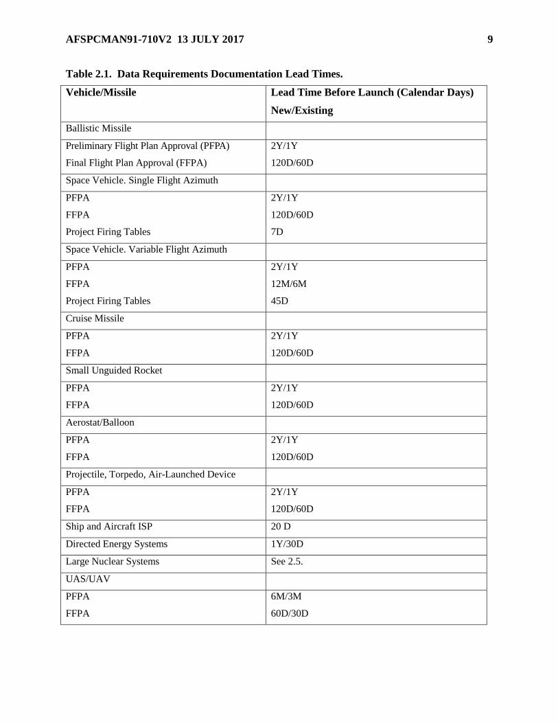
Table 2.1. Data Requirements Documentation Lead Times.
Vehicle/Missile Lead Time Before Launch (Calendar Days)
New/Existing
Ballistic Missile
Preliminary Flight Plan Approval (PFPA)
Final Flight Plan Approval (FFPA)
2Y/1Y
120D/60D
Space Vehicle. Single Flight Azimuth
PFPA
FFPA
Project Firing Tables
2Y/1Y
120D/60D
7D
Space Vehicle. Variable Flight Azimuth
PFPA
FFPA
Project Firing Tables
2Y/1Y
12M/6M
45D
Cruise Missile
PFPA
FFPA
2Y/1Y
120D/60D
Small Unguided Rocket
PFPA
FFPA
2Y/1Y
120D/60D
Aerostat/Balloon
PFPA
FFPA
2Y/1Y
120D/60D
Projectile, Torpedo, Air-Launched Device
PFPA
FFPA
2Y/1Y
120D/60D
Ship and Aircraft ISP 20 D
Directed Energy Systems 1Y/30D
Large Nuclear Systems See 2.5.
UAS/UAV
PFPA
FFPA
6M/3M
60D/30D

10 AFSPCMAN91-710V2 13 JULY 2017
2.2. Flight Plan Approval and Data Requirements Overview. Flight plan approval (FPA) is
applicable to the following programs: ballistic missile and space vehicles; cruise missiles; small
unguided rockets or probes; aerostats or balloon systems; projectiles, torpedoes, non-propulsive
air-dropped bodies, or any small devices to be flight tested.
2.2.1. Approval Phases. The FPA process incorporates two formal approval phases:
Preliminary Flight Plan Approval (PFPA) and Final Flight Plan Approval (FFPA).
2.2.1.1. Programs usually fall into two categories: new or existing. New programs
include existing programs whose FPA supporting data has changed significantly. New
programs shall submit the data requirements for both PFPA and FFPA. Existing
programs generally shall submit the data requirements for only FFPA. For either new or
existing programs that do not involve long lead times for planning or payload
development, formal approval may, of necessity, occur only a few months before the
desired operation date.
2.2.1.2. In each FPA phase, Wing Safety shall respond to the Range User’s written
request for approval in one of the following ways: (1) by issuing a letter of approval, (2)
by issuing a letter of disapproval, (3) by requesting that a change in the proposed plan be
made or evaluated, or (4) by requesting additional data. After all the requested data have
been provided and evaluated, the Range User shall be given an “approval,” “conditional
approval,” or “disapproval” letter. If the flight plan or mission is approved, the letter shall
specify the conditions of approval pertaining to such things as launch azimuth limits,
trajectory shaping, wind restrictions, locations of impact areas, times of discrete events,
and number of operations for which the approval applies. The approval shall be final as
long as the operation(s) remain within the stated conditions. If significant changes to the
flight plan occur after approval has been granted, further analysis of the revised plan may
be necessary. The Range User is responsible for advising Wing Safety of any such
changes or anticipated changes as early as possible.
2.2.2. Data Requirements. Data requirements for the PFPA and FFPA are found in two
chapters of this volume. The requirements in Chapter 2 apply to all programs. Requirements
for specific programs, including detailed analyses, are in Chapter 3 of this volume. All
requirements may be tailored by Wing Safety, as required. The Preliminary Flight Data
Package (PFDP) and the Final Flight Data Package (FFDP) are submitted in support of the
PFPA and FFPA, respectively. The data packages may be submitted in any convenient
format. The following general format, which conforms to the order in which requirements are
established, is suggested for any Range User who desires a standard submission form. If this
format is adopted and the information submitted in response to a requirement cannot easily
be placed in the data package, it should be made an appendix to the specific part. For
example, compact disks and listings for trajectories would be an appendix to Part III in the
format shown below:

AFSPCMAN91-710V2 13 JULY 2017 11
Figure 2.1. General Format.
2.2.3. Preliminary Flight Plan Approval (PFPA) and Data Package Requirements.
2.2.3.1. PFPA. The FPA process for all new programs begins with an introductory
meeting followed by the submittal of required data and a formal written request for a
PFPA. Existing programs shall also request a PFPA when previously approved
supporting data is not applicable to the planned operation. The purpose of the PFPA is to
ensure Wing Safety requirements are included in the overall system design and to
determine if the specific program is conceptually acceptable. In preliminary meetings,
Wing Safety can define acceptable flight limits and conditions, specify which parts of the
flight plan need special emphasis, and identify requirements applicable to the program.
Data regarding anticipated flight trajectories, booster configuration, and flight
termination system (FTS) configuration shall be included in the PFPA. Lack of some
pertinent data should not be cause for delaying the initial written request, particularly if
preliminary discussions have not been held. The Range User should begin PFPA action
during the Preliminary Design Review (PDR) phase of the program planning or, in any
event, immediately after Wing Safety has replied to the Program Introduction (PI) in a
Statement of Capability. For new programs, the PFPA usually occurs at least two years
(one year for existing programs) before the planned operation.
2.2.3.2. Preliminary Flight Data Package Requirements. In addition to the program-
specific requirements listed in Chapter 3 of this volume, the PFPA data package shall
include the following:
2.2.3.2.1. Basic program description and objectives including number, designation,
and purpose of operation(s) for which the proposed flight plan is applicable.
2.2.3.2.2. General operation scenarios and proposed target areas and a statement
indicating whether the proposed trajectory (or flight plan) is similar to some prior
operation.
2.2.3.2.3. Intended launch or flight test date(s).
2.2.3.2.4. Map and listing of downrange and crossrange vacuum instantaneous
impact points (IIPs) for each second of powered flight time.
2.2.3.2.5. General description of launch vehicle and payload in sufficient detail for
hazard assessment providing the following information:
2.2.3.2.5.1. Type, weight, and TNT equivalency of all propellants.
2.2.3.2.5.2. Description of ordnance items.
2.2.3.2.5.3. Description of toxic and radioactive materials.
2.2.3.2.5.4. Characteristics of high pressure vessels, lasers, and batteries.
12 AFSPCMAN91-710V2 13 JULY 2017
2.2.3.2.5.5. Description of materials, thickness, and safety factors of pressure
vessels.
2.2.3.2.5.6. Thrust and burn times of motors and thrusting devices.
2.2.3.2.5.7. Description of guidance and control system.
2.2.3.2.5.8. Drawings and diagrams showing structural arrangement and layout of
significant components in each stage or payload.
2.2.3.2.6. General description and location of the airborne FTS (made up of the
command and automatic destruct subsystems) or statement indicating that the planned
system is similar to one already in use. Wing Safety shall be involved before the PDR
time frame if a new design is to be considered.
2.2.3.2.7. Preliminary estimate of fragment characteristics such as number,
composition, dimensions, and weight due to all potential modes of vehicle breakup
such as destruct and aerodynamic loading.
2.2.3.2.8. Tracking aids such as C-Band transponder, global positioning system
(GPS) receivers/translators installed in the vehicle that can be used for flight safety
purposes and their locations in the stages or sections.
2.2.3.2.9. Telemetry measurement listing and data word definitions.
2.2.3.2.10. Description of launch site facilities, support buildings, and the structural
integrity information for each of these.
2.2.3.2.11. Geodetic latitude, longitude, and designation of proposed launch site, or
location on the earth’s surface for launches that occur above or below the earth’s
surface; if launch or test initiation can occur inside an area rather than at a single
specified location, this area shall be defined.
2.2.3.2.12. Launch azimuth for single azimuth launches or desired azimuth sector(s)
for variable azimuth launches.
2.2.3.2.13. Estimates of the nominal impact point and the three-sigma drag-corrected
dispersion area for each jettisoned body.
2.2.3.2.14. Buoyancy analysis of all jettisoned bodies that impact water; for bodies
that remain buoyant after impact and present a hazard to maritime vessels or
platforms, a means of sinking or recovering the body is required. If recovery is
desired, a recovery procedure shall be identified. The buoyancy analysis shall include
the following:
2.2.3.2.14.1. Description of object, size, weight, general description of materials,
and color.
2.2.3.2.14.2. Description of object’s orientation in water. If more than one
orientation is possible, then provide probabilities for each orientation.
2.2.3.2.14.3. Time duration measured from impact it will take the body to
completely sink below deepest draft of expected vessels in area. If more than one
orientation is possible, then provide time durations for each orientation.
AFSPCMAN91-710V2 13 JULY 2017 13
2.2.3.2.14.4. Plot showing potential regions of drift based on nominal impacts. If
more than one orientation is possible, then annotate on the map when each
orientation would sink.
2.2.3.2.14.5. Description of any hazardous items, such as unexploded ordinance,
pressure vessels, and hazardous chemicals.
2.2.3.2.14.6. Description of vessel types that the body would pose a hazard to,
and the rationale.
2.2.3.2.14.7. If requested to provide a hazard analysis predicting probability of
contact with maritime traffic, include sources of data and vessel classifications.
2.2.3.3. Reliability and Malfunction Analysis Data Requirements. Reliability of each
stage and probability of a normal mission or failure rate data for each stage shall be
provided. The following data shall be provided:
2.2.3.3.1. Description of failure modes that can result in an abnormal flight. An
analysis of all subsystems shall be made to determine failure modes that would result
in a catastrophic event. Typical malfunctions that should be considered include failure
of the propulsion system, failure of the hydraulic and electrical systems, failure of the
guidance and control system, failure of separation mechanisms between stages,
failures that lead to premature thrust termination, overshoot, or shifting of the
platform reference.
2.2.3.3.2. An estimate for the probability of occurrence or failure rate (versus time)
for each failure mode and an explanation of the method(s) used for the estimate; any
other information considered pertinent with respect to critical portions of flight, such
as vehicle stability characteristics and structural limits.
2.2.3.3.3. Description of all credible failed vehicle response modes. A response mode
is a category of vehicle dynamic response, including vehicle breakup, which results
from one or more failure modes. At a minimum, the response modes should include
on-trajectory failures such as thrust termination and explosion and malfunction turn
failures (loss of thrust vector control, tumble turn, nozzle burn-through failures). On-
trajectory failures should be subdivided according to the type of breakup (for
example, aerodynamic or explosive) that will result. Malfunction turn failures should
be subdivided into tumble turns and trimmed turns if trimmed turns are a credible
response mode.
2.2.3.3.4. Summary of past vehicle performance giving number launched, launch
location, number that performed normally, and number that malfunctioned, behavior
and actual (if available) or estimated impact location (of the vehicle or vehicle debris)
for those that malfunctioned, time and nature of malfunction, and corrective action.
2.2.3.4. Propellant Description. If a vehicle has the capability of exploding as a result
of self-initiation, FTS activation, or ground or water impact or if a vehicle uses
propellants that are toxic in gaseous or vapor states due to combustion or release to the
atmosphere, the following data shall be provided:
14 AFSPCMAN91-710V2 13 JULY 2017
2.2.3.4.1. Types of propellant or a statement indicating the same propellant
formulation is already in use. The following thermodynamic and chemical
information shall be provided for each propellant type used on the vehicle:
2.2.3.4.1.1. List of major chemical constituents. A major constituent is defined as
a chemical component that (1) constitutes more than 1 percent of the propellant
mass, (2) is a toxic chemical, or (3) produces a toxic combustion product. The list
of combined constituents shall account for at least 99 percent of the total
propellant mass.
2.2.3.4.1.2. Chemical formula for each major constituent.
2.2.3.4.1.3. Mass fraction of each major constituent relative to the total mass
propellant.
2.2.3.4.1.4. Reference temperature of chemical constituents in their normal state;
for example 25oC.
2.2.3.4.1.5. Enthalpy of formation for each chemical constituent at the reference
temperature (calorie/gram-mole).
2.2.3.4.1.6. Designation of each chemical constituent as fuel or oxidizer (F or O).
2.2.3.4.1.7. Molecular weight of each chemical constituent.
2.2.3.4.2. TNT equivalency of remaining propellant versus flight time and explosion
scenario for each separate stage (or motor) and each possible combination of stages
that could result from malfunction conditions.
2.2.3.4.3. An estimate of the probability of explosion versus flight time for each of
the following: self-initiation, FTS activation, and ground or water impact. A
comprehensive description of the methods used to derive the estimate shall be
provided.
2.2.3.4.4. Description of methods used to minimize the possibility of explosion.
2.2.3.4.5. Time of day when launches will be scheduled and the number of launches.
2.2.3.4.6. Maximum total quantities of liquid and solid propellants.
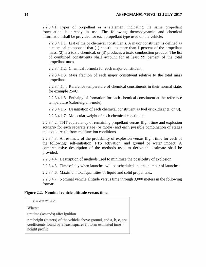
2.2.3.4.7. Nominal vehicle altitude versus time through 3,000 meters in the following
format:
Figure 2.2. Nominal vehicle altitude versus time.
AFSPCMAN91-710V2 13 JULY 2017 15
2.2.3.4.8. Exhaust plume heat content (calorie/gram), mass flux (gram/second), and
chemical composition (mass fractions and chemical species) for all motors ignited at
liftoff. This data shall be evaluated at a point sufficiently far downstream from the
nozzle exit plume such that plume afterburning is essentially complete and the plume
has expanded and cooled sufficiently to allow high temperature combustion species to
have completed recombination actions. Total mass flux shall indicate nominal engine
burn propellant mass flux as well as entrained air mass flux. Documentation of this
data shall include reference to the method of calculation, distance downstream from
the nozzle, possible chemical interactions between main engines and strap-on
boosters (if appropriate), and radiation heat loss. Chemical composition of the plume
shall cover all major species such that (1) at least 99 percent of total plume mass is
represented, and (2) all major toxic species are included. Chemical species of concern
to Wing Safety include, but are not necessarily limited to, hydrogen chloride, carbon
dioxide, carbon monoxide, aluminum oxide, hydrazine, unsymmetrical dimethyl-
hydrazine, monomethyl hydrazine, nitrogen tetroxide, nitrogen dioxide, nitric acid,
nitrosodi-methylamine, formaldehyde dimethyl hydrazine, benzene, toluene, and
other volatile organic compounds.
2.2.3.4.9. Solid propellant burn time (seconds) and average burn rate
(grams/seconds) for propellant fragments burning at 1 atmosphere of pressure
following an accidental FTS-initiated destruct for each motor containing solid
propellant. Fuel fragmentation assumptions (number and size of fragments, surface
area, inches/second burn rate) used to generate the average solid propellant burn time
and mass burn rate shall be included.
2.2.3.4.10. Liquid propellant expenditure rate (grams/seconds) for nominal launch
for the first 3,000 meters of vehicle ascent.
2.2.3.4.11. For catastrophic abort or FTS vehicle destruct of vehicles using liquid
propellants, the information described below is required to support Wing Safety toxic
risk analyses. Depending on the similarity of the program vehicle’s propellants to
existing vehicle propellants, the Range User may be required to perform significant
additional technical analyses to provide this information.
2.2.3.4.11.1. Percentages of available liquid fuel and oxidizer mixed and reacted
within each stage during the first several hundred milliseconds of the initiating
destruct mechanism.
2.2.3.4.11.2. Percentage of available liquid propellants mixed and reacted during
the active fireball burn phase that typically last several seconds past the initiating
event. Provide assumptions about the degree of mixing and the nature of chemical
reaction between vehicle stages, including solid rocket motors and the extent of
air entrainment and after-burning of fuel species.
2.2.3.4.11.3. Percentage of available liquid propellants dispersed by vehicle
explosion that do not undergo chemical reactions but remain as vaporized
unreacted propellant. The objective of obtaining this information is to characterize
and quantify the types of chemical reactions among the vehicle propellants so that
the chemical composition and total heat content of the liquid propellant fireball
can be computed from input reactant data.

16 AFSPCMAN91-710V2 13 JULY 2017
2.2.3.4.12. Initial Exhaust Cloud Data. The following information shall be provided
to specify the initial parameters required to calculate buoyant cloud rise in support of
Wing Safety toxic risk analyses. These values describe the exhaust ground cloud
when the horizontal momentum produced by the ducting or reflection in the launch
mount becomes negligible compared to the buoyant forces within the cloud for the
nominal launch scenario. Depending on the similarity of the program vehicle to
existing vehicles, the Range User may be required to perform significant additional
technical analyses to provide this information.
2.2.3.4.12.1. Initial exhaust ground cloud radius for normal launches. Assume a
spherical cloud with a volume equivalent to that estimated for the actual ground
cloud.
2.2.3.4.12.2. Initial radius of the area over which solid propellant fragments are
dispersed due to a vehicle abort on the pad. For aborts during the first 50 seconds
of flight, provide estimates of solid propellant fragment number, size, mass,
ballistic coefficient, explosion-induced fragment velocity, and nominal vehicle
position; and, at 10-second intervals, velocity vector.
2.2.3.4.12.3. Vertical velocity of the ground cloud centroid for nominal launch
cases.
2.2.3.4.12.4. Initial ground cloud centroid height (meters above ground level
[AGL]).
2.2.3.5. Explosive Reentry Vehicle or Warhead Information. An operation that
includes the use of an explosive reentry vehicle (RV) or warhead shall not be conducted
without the approval of the Space Wing Commander. For these operations, the following
data are required:
2.2.3.5.1. A complete justification for the proposed operation.
2.2.3.5.2. The proposed position and altitude of the RV or warhead detonation point.
2.2.3.5.3. The effects of the detonation on the missile and RV or warhead in terms of
number, weights, cross-sectional areas, ballistic coefficients, and velocities imparted
to the pieces.
2.2.3.5.4. The impact dispersion area for all fragments including diffusion and
dispersion of any toxic or radioactive clouds or fragments and the radiation exposure
characteristics.
2.2.4. Final Flight Plan Approval (FFPA) and Data Package Requirements.
2.2.4.1. FFPA. The FFPA is applicable to each program operation. The FFPA is based
on detailed analyses of the operation objectives, vehicle performance, and other data
items required. In response to the Range User request, the FFPA is issued when the Chief
of Safety is satisfied that a specific operation can be supported within the limits of flight
safety control capabilities to provide positive protection to life and property. Any
constraints or conditions identified in the PFPA may be superseded by those stated in the
FFPA. The FFPA applies to a specific operation and does not guarantee that similar
operations will receive an FFPA. If a program consists of identical operations, a blanket
FFPA may be granted that would remain in effect throughout the life of the program as
AFSPCMAN91-710V2 13 JULY 2017 17
long as the operations remain within the specified safety constraints. The request for
FFPA and the supporting data are typically received by Wing Safety at 120 calendar days
(new programs) or 60 calendar days (existing programs) before the planned operation.
Past data submittals may be referenced if that data has not changed from previous
operations.
2.2.4.2. Final Flight Data Package Requirements.
2.2.4.2.1. General. These data requirements apply to requests for FFPA for all
programs specified in 2.2. The analysis-specific data requirements in Chapter 3, 3.1
through 3.7 of this volume are also required before an FFPA is issued. The FFDP
shall include items that were changed from or not provided in the PFDP. The FFDP is
made up of the data requirements used to produce the final set of operational rules
and flight control criteria and ensures all data complies with the conditions of the
PFPA and data format requirements. The request for FFPA shall specify the operation
designation, intended operation date, and references to all applicable supporting data
products. In meeting the FFPA requirements, some of the information submitted by
the Range User may not change from the PFDP or from operation to operation. In
such cases, the information need be supplied only once. However, for each operation,
the Range User shall state in writing which supporting data are applicable and specify
the document, page number, and paragraph where each required item can be found. In
other cases where the proposed plan deviates from the PFPA or previously accepted
limits, additional data shall be provided.
2.2.4.2.2. Limits of a Useful Mission.
2.2.4.2.2.1. These data requirements apply solely to space operations. They are
used to establish guidelines or limits for land overflight prior to orbital insertion.
2.2.4.2.2.2. The permissible limits for overflight depend not only on this data, but
also on estimated overflight hazards, the operational objectives, and the
importance of these objectives. The Range User shall provide the following data:
2.2.4.2.2.2.1. Launch azimuth limits for which the primary operation
objectives can be met and for which a useful orbit can be attained.
2.2.4.2.2.2.2. Operational objectives that will be met or the extent to which
the primary objectives will be degraded.
2.2.4.2.2.2.3. Description of limiting orbit(s) (apogee, perigee, period, and
inclination) as a function of overflight azimuth.
2.2.4.2.2.2.4. Circumstances or types of malfunctions that could cause the
vehicle to fly outside the three sigma limits of normality, but remain within
the limits for which a useful orbit can be attained.
2.2.4.2.2.2.4.1. The probability of occurrence of these malfunctions.
2.2.4.2.2.2.4.2. The affects of these malfunctions on the success of
succeeding burns or stages.

18 AFSPCMAN91-710V2 13 JULY 2017
2.2.4.2.2.2.5. The most lofted and depressed trajectories for which the
primary operation objective can be met and for which a useful orbit can be
attained, given the information requested in 2.2.4.2.2.2.1 through
2.2.4.2.2.2.4.2. In deriving these trajectories, only perturbations that result in
deviations in the pitch plane shall be considered. If these trajectories cannot be
provided to Wing Safety, any one of the following may be substituted:
2.2.4.2.2.2.5.1. If the stage that achieves orbit does not contain an FTS, the
Range User shall provide the upper and lower altitude limits at shutdown of
the last suborbital stage if the succeeding stage is to attain a useful orbit.
2.2.4.2.2.2.5.2. If the stage that achieves orbit contains an FTS, the Range
User shall provide the upper and lower altitude limits as the vacuum impact
point reaches the continent to be overflown by the first orbital stage if this
stage is to attain a useful orbit.
2.2.4.2.2.2.5.3. The Range User shall provide the minimum impact range
that the last suborbital stage must achieve, if the succeeding stage is to attain
a useful orbit and a minimum orbit (perigee > 70 nautical miles).
2.2.4.2.3. Solid Propellant Data Requirements. The following data are required
for solid propellants:
2.2.4.2.3.1. Burning rate of solid propellants, in inches/second, as a function of
pressure, including ambient atmospheric pressures.
2.2.4.2.3.2. Percent propellant TNT equivalency for each stage as a function of
relevant impact parameters, such as weight of propellant, impact velocity, surface
composition, and impact geometry.
2.2.4.2.3.3. Stage ignition and burntime, propellant weight versus time, and
propellant density.
2.3. Aircraft/Ship Intended Support Plans (ISP) and Data Package Requirements.
2.3.1. Purpose. The purpose of the ISP approval is to ensure maximum safety consistent
with the operation objectives. To the extent possible, this means that support positions and
flight plans can be established outside a 1x10⁻⁵ hit-probability contour for a specific support
aircraft, or outside a 1x10⁻⁴ hit-probability contour for a specific support vessel. When the
required support data cannot be collected from such remote locations, support positions
located in relatively hazardous areas shall be carefully planned to minimize the ship or
aircraft hit probability. Hazards to ships and aircraft exist primarily in the launch area, along
the flight azimuth where jettisoned stages and components reenter and breakup, and in the
target area where reentry vehicles and final stages impact. ISP approval is applicable to each
ship and aircraft supporting an operation requirement identified in the Universal
Documentation System (UDS) or participating in an operation on a non-interference basis.
Additional information for control of 45 SW test support aircraft is provided in 45 SWI 13-
201, Eastern Range Air Space Management Procedures. Similar regulations for ships do not
exist.

AFSPCMAN91-710V2 13 JULY 2017 19
2.3.2. ISP Development and Submittal. ISPs for ships and aircraft shall be developed
either by the Range User or by support agencies that are responding to requirements
contained in the PRD or the Operations Requirements (OR). In either case, the developing
organization shall furnish the ISP for review and approval, either directly to Wing Safety or
through the Range Squadron.
2.3.3. ISP Data Package Requirements. For operations requiring support aircraft or ships,
the Range User shall provide the following additional information 20 calendar days before
the mission. All identifying points and positions shall be time correlated using the operation
start time as a reference.
2.3.3.1. Aircraft Flight Profile Requirements:
2.3.3.1.1. Type of aircraft.
2.3.3.1.2. Aircraft physical dimensions as described in Jane’s aircraft publications.
The following data shall be provided as a minimum:
2.3.3.1.2.1. One-half wing span – the length of the wing measured from the
fuselage to the wing tip edge.
2.3.3.1.2.2. Maximum width of the fuselage measured in the top view.
2.3.3.1.2.3. Average thickness of the wing measured in the side view.
2.3.3.1.2.4. Average fuselage thickness measured in the side view.
2.3.3.1.2.5. Overall area (in square feet) measured in the top view.
2.3.3.1.2.6. Overall perimeter (in feet) measured in the top view.
2.3.3.1.3. Call sign.
2.3.3.1.4. Registration Number ("N" number).
2.3.3.1.5. Tail number.
2.3.3.1.6. Warning area and mission area penetration points (entry and exit).
2.3.3.1.7. Holding fixes and altitudes.
2.3.3.1.8. Primary and alternate Mission Support Positions (MSPs), including
geodetic latitude, longitude, heading, speed, and time of arrival.
2.3.3.1.9. Written and graphic flight path location describing the maneuvers within
200 miles of the MSP giving orbit or loiter locations, positions along ground track in
latitude and longitude, turn points, turn radii where applicable, speeds, and headings.
2.3.3.1.10. Course, speed, and altitudes from the MSP to the terminal end of the data
run.
2.3.3.1.11. Departure route after mission completion, including maneuvers for
departure to recovery base.
2.3.3.1.12. Final staging and recovery bases.
2.3.3.2. Ship Cruise Profile Information:
2.3.3.2.1. Class of ship.
20 AFSPCMAN91-710V2 13 JULY 2017
2.3.3.2.2. Dimensions of ship measured in the top view.
2.3.3.2.3. Call sign.
2.3.3.2.4. Registration Number.
2.3.3.2.5. Name.
2.3.3.2.6. Warning area and mission area penetration points (entry and exit).
2.3.3.2.7. Primary and alternate MSPs including geodetic latitude, longitude, heading
and speed.
2.3.3.2.8. Course and speed from the MSP to the terminal end of the data run.
2.3.3.2.9. Planned location (support plan), both written and graphic, of the vessel
during the period from launch until operation termination or impact.
2.4. Directed Energy Plan Approval and Data Requirements. These requirements apply to
all forms of directed energy systems. Laser design, test, and documentation requirements are also
addressed in Volume 3, Chapter 8.2., Laser Systems, of this publication. Reasonable and
prudent operational procedures shall be established so that hazards from directed energy system
operations present virtually no risk to the general public.
2.4.1. Purpose. The purpose of the Directed Energy Plan (DEP) approval is to ensure the
operation is conducted safely with consideration for the operation requirements and national
need. The DEP approval applies to programs using directed energy systems. These systems
include, but are not limited to, lasers and neutral particle and ion beams, with any
combination of surface, air, or space locations for the energy source and target. In this
volume, the term laser is used as a generic reference to all directed energy systems. In
general, those laser operations in the following categories are subject to review:
2.4.1.1. Laser operations requesting range support through the provision of the UDS.
2.4.1.2. Laser illumination, for which an Operations Directive (OD) does not exist,
conducted in conjunction with a scheduled range operation for which an OD does exist.
2.4.1.3. Laser operations having the potential to impair Wing Safety controls or reduce
the reliability of Wing Safety systems.
2.4.2. DEP Submittal.
2.4.2.1. Requests for DEP approval shall be forwarded directly to Wing Safety or
through either the Plans Office for new programs or the Range Squadron for existing
programs. Lead times and requirements may vary and shall be tailored depending on the
specific characteristics of the system and proposed operating scenarios. Lead times for
data requirements reflect the dependence of mission success on planned laser operations.
For instance, laser operations performed on a non-interference basis using scheduled
launches as a target of opportunity will have lead times different from directed energy
activities that are integral to a scheduled operation.
2.4.2.2. Laser operations considered mandatory by the Range User shall be included as
part of the Program Introduction (PI). If the laser operation is not mandatory IAW Range
User requirements, the initial request for laser program approval is desired at least one
year before the planned operation date.

AFSPCMAN91-710V2 13 JULY 2017 21
2.4.2.3. Requests for Wing Safety review of recurring laser operations are desired 30
calendar days before each planned operation date.
2.4.2.4. Modifications to existing laser systems or changes to current operating plans
should be discussed with Wing Safety during the planning phase to determine the need
for additional data requirements and establish mutually agreeable lead times for
submission of additional data.
2.4.3. Laser Operational Procedures.
2.4.3.1. Avoidance Volume.
2.4.3.1.1. The avoidance volume shall encompass that portion of the laser beam that
is capable of causing either permanent or temporary ocular impairment.
2.4.3.1.2. The computation of the avoidance volume radial distance from the center
of the laser beam shall consider, at a minimum, the following variables:
2.4.3.1.2.1. Time delays between aircraft detection and laser termination.
2.4.3.1.2.2. Average aircraft speeds.
2.4.3.1.3. Laser operating parameters and the reliability of system controls.
2.4.3.1.4. Laser beam azimuth and elevation restrictions shall be defined so that the
laser beam avoidance volume is constrained to airspace for which an approved
surveillance capability has been established.
2.4.3.2. Airspace Surveillance.
2.4.3.2.1. Organizations conducting laser operations shall provide for an airspace
surveillance capability and procedures that ensure the laser operation can be
terminated before a non-participating aircraft enters the pre-defined laser beam
avoidance volume.
2.4.3.2.2. The American National Standard Institute (ANSI) ANSI Z136.1, Safe Use
of Lasers, and ANSI Z136.6, Safe Use of Lasers Outdoors, require coordination with
the Federal Aviation Administration when laser programs include the use of Class 3a,
3b, and 4 lasers within navigable airspace. For Wing Safety purposes, air space
control is a desirable safety measure; however, it is considered a secondary protection
measure to surveillance requirements. Airspace controls shall be initiated by Wing
Safety when the value added to safety is justifiable.
2.4.3.3. Weather Constraints. The laser operation shall be terminated during periods
when weather conditions obstruct or adversely affect an approved surveillance method.
2.4.4. DEP Data Package Requirements.
2.4.4.1. General Data. The following data are required for each operation or group of
operations. Additional data may be required depending on the laser system.
2.4.4.1.1. Complete description of surveillance methods, surveillance range limits,
and a description of the procedures used to terminate laser operations when
necessary.
2.4.4.1.2. General information on the purpose of the operation.
22 AFSPCMAN91-710V2 13 JULY 2017
2.4.4.1.3. Description of the laser and its operation.
2.4.4.1.4. Laser classification IAW ANSI Z136.1.
2.4.4.1.5. Description of operation scenarios and proposed target areas.
2.4.4.1.6. Copies of safety analyses and test procedures conducted on the system.
2.4.4.1.7. Laser Emission Characteristics:
2.4.4.1.7.1. Mode of operation (continuous wave or pulsed).
2.4.4.1.7.2. Wavelength (nanometers).
2.4.4.1.7.3. Energy per pulse in Joules for pulsed lasers or power in watts for
continuous wave lasers.
2.4.4.1.7.4. Pulse repetition frequency (Hertz).
2.4.4.1.7.5. Pulse width and separation (seconds).
2.4.4.1.7.6. Beam diameter – the diameter of a circular beam at a point where the
intensity drops to 1/e (0.368) of its maximum value usually located at the exit
aperture or at the waist if convergent beam (centimeters).
2.4.4.1.7.7. Beam divergence angle at the aperture or waist (radians).
2.4.4.1.8. Number and designation of laser operations to which the proposed
operation applies.
2.4.4.1.9. A statement indicating whether the proposed operation is similar in its
safety aspects to that of some prior operation for which documentation is available.
2.4.4.1.10. Intended operation dates.
2.4.4.1.11. Functional description of the target acquisition and laser firing process
and of any error/failure detection and correction or termination capability, including
its reliability and response time.
2.4.4.2. Scenario Type. The scenario type can be any combination of the following:
2.4.4.2.1. Fixed laser and/or target.
2.4.4.2.2. Moving laser and/or target.
2.4.4.3. Laser and Target(s) Position Data.
2.4.4.3.1. Fixed – latitude, longitude, and altitude where laser beam exits the
protective housing of each target.
2.4.4.3.2. Moving – position and velocity vector versus time of each object in an
Earth Centered Earth Fixed (ECEF) Coordinate System.
2.4.4.4. Nominal Operation Scenario Data. The following information shall be
provided:
2.4.4.4.1. Desired operating azimuth and elevation sectors.
2.4.4.4.2. Event times; for example, acquisition, arming, and firing on/off times.

AFSPCMAN91-710V2 13 JULY 2017 23
2.4.4.4.3. Duration of each laser firing (seconds).
2.4.4.4.4. Slew rate (radians/seconds).
2.4.4.4.5. Hardware and software stops (angles from forward direction, radians).
2.4.4.4.6. Pointing accuracy (radians); brief description of laser beam pointing aids
including their location.
2.4.4.4.7. Laser platform/vehicle attitude control accuracy (static, radians; dynamic,
radians/seconds).
2.4.4.5. Target Data:
2.4.4.5.1. Target size - radius or height, width, and length.
2.4.4.5.2. Orientation - angle of each target surface with respect to the incident beam.
2.4.4.5.3. Type of reflection possible, such as specular or diffuse.
2.4.4.5.4. Reflection coefficients.
2.4.4.6. Exposure Controls. Exposure controls shall be calculated IAW ANSI Z136.1.
2.4.4.6.1. Maximum Permissible Exposure (MPE) level, nominal optical hazard
distance in vacuum, and other applicable hazard ranges for each laser.
2.4.4.6.2. Description of the maximum region around each target that can be
subjected to the hazard during a nominal operation.
2.4.4.6.3. Reflection characteristics of other significant objects in the hazard region
around each target. The hazard region is the zone where the laser radiation levels may
exceed the MPE level.
2.4.4.7. Risk Study. In some instances, laser operations may include test parameters or
characteristics that may not allow for the laser beam to be safely contained within a
predicted control volume. In such cases, Wing Safety may require a risk study. If a risk
study is required, the following data shall be submitted:
2.4.4.7.1. Probability of Occurrence Data. The probability of occurrence versus time
of operation for each of the following generic hazard modes (modes of beam control
error or failure): Pointing Error, Inadvertent Slewing, Premature Firing, Delayed
Firing, Beam Focusing Error, Loss of Focus, and other modes such as Wrong Target
Acquisition applicable to the system. If the probability of occurrence is non-zero for
any of these hazard modes, then probability distributions for the random hazard mode
parameters describing how each mode can occur over time shall be provided. The
following parameters describe each of the stated failure modes:
2.4.4.7.1.1. Pointing Error Hazard Mode. Offset angle (radians) between the
correct laser system to target pointing direction and the incorrect pointing
direction (angle assumed constant during a firing).
2.4.4.7.1.2. Inadvertent Slewing Hazard Mode:
2.4.4.7.1.2.1. Time (seconds) during firing at which the inadvertent slewing
starts.
24 AFSPCMAN91-710V2 13 JULY 2017
2.4.4.7.1.2.2. Azimuth angle (radians measured from North) of the slew
plane; it is assumed that, over time, the laser-to-target line remains contained
in a plane.
2.4.4.7.1.2.3. The angular rate (radians/seconds) of slewing in the plane (rate
assumed constant).
2.4.4.7.1.2.4. Duration of the slewing (seconds), if other than that of the
nominal firing time remaining after the start of the slewing.
2.4.4.7.1.3. Premature Firing Mode. The number of seconds before the nominal
start time that laser firing occurs.
2.4.4.7.1.4. Delayed Firing Termination Mode. The number of seconds after the
nominal termination time that laser cutoff occurs.
2.4.4.7.1.5. Beam Focusing Error Mode. The range (meters) along the laser-to-
target vector at which the convergent beam is misfocused; the incorrect range can
either be too long or too short relative to the nominal focus range.
2.4.4.7.1.6. Loss of Focus Mode:
2.4.4.7.1.6.1. Time (seconds) during firing at which the loss of focus occurs.
2.4.4.7.1.6.2. Beam divergence angle (radians) that measures the spreading of
the beam (assumed to remain centered on the laser-to-target vector).
2.4.4.7.2. Failure Modes, Effects, and Criticality Analysis (FMECA):
2.4.4.7.2.1. Applicable hazard modes shall be defined and documented by a
FMECA IAW MIL-STD-1629 and BSR/ANSI/AIAA S-102.2. 4-2015,
Capability-Based Product Failure Mode, Effects and Criticality Analysis
requirement, or the equivalent.
2.4.4.7.2.2. Their probabilities of occurrence and the probability distributions of
their descriptive parameters shall be quantified with fault tree analysis or the
equivalent.
2.4.4.7.2.3. The level of analysis conducted in each case shall be the level at
which appropriate component error/failure data are available.
2.4.4.7.2.4. If necessary for confidence in the results, analyses of the effects of
the uncertainties in the component data shall be carried out.
2.4.4.7.3. Alternative Data Submission. The Range User may arrange to have the risk
study done by Wing Safety. The following data shall be provided to support this
option:
2.4.4.7.3.1. System design description and performance data and functional and
reliability block diagrams for portions of the system affecting beam control,
including platform attitude control.
2.4.4.7.3.2. Associated component (including hardware, software, and human)
reliabilities or, at a minimum, component and component environment
descriptions allowing the estimation of these reliabilities.
AFSPCMAN91-710V2 13 JULY 2017 25
2.4.5. Coordination with the United States Strategic Command (USSTRATCOM)
Laser Clearinghouse , Cheyenne Mountain Operations Center (CMOC) Space Control
Division CMOC/J3S, is required for all Class 3 and 4 lasers operated outside of a confined
laboratory environment. Unless waived by USSTRATCOM CMOC/J3S, firing time
coordination for those systems shall be accomplished to verify that on-orbit objects of
national interest are not affected by the laser operation.
2.5. Large Nuclear Systems Approval and Data Requirements. Range Users employing
radioactive materials that exceed the limits established by the Office of Science Technology
Policy (OSTP) shall comply with Presidential Directive/National Security Council 25, Scientific
or Technological Experiments with Possible Large Scale Adverse Environmental Effects and
Launch of Nuclear Systems into Space. The Range User shall provide Wing Safety with a copy
of the following documents. Nuclear system design, test, and documentation requirements are
also addressed in Volume 3 of this publication.
2.5.1. Environment Impact Statement: L-3 years.
2.5.2. Final Safety Analysis Report: L-1 year.
2.5.3. Interagency Nuclear Safety Review Panel (INSRP) Safety Evaluation Report: L-7
months. In the event that the INSRP is not impaneled by the OSTP, the provisions of the
latest version of AFI 91-110, Nuclear Safety Review and Launch Approval for Space or
Missile Use of Radioactive Material and Nuclear Systems, shall be performed by the Chief,
Weapons, Space and Nuclear Safety Division and the results provided to Wing Safety in lieu
of the INSRP Safety Evaluation Report.
2.5.4. Certification of Presidential Approval for Flight: L-10 days. A copy of the OSTP
approval letter or the National Security Council approval letter meets this certification
requirement.

26 AFSPCMAN91-710V2 13 JULY 2017
Chapter 3
PROGRAM-SPECIFIC FLIGHT ANALYSES
3.1. Trajectory Analysis.
3.1.1. General. The Range User shall perform a trajectory analysis to determine a vehicle’s
nominal trajectory and potential three-sigma trajectory dispersions about the nominal
trajectory. The Range User’s trajectory analysis shall also determine, for any time after
liftoff, the limits of a launch vehicle’s normal flight. “Normal flight” is defined as a properly
performing vehicle whose real-time IIP does not deviate from the nominal IIP by more than
those of three-sigma dispersed trajectories generated according to Attachment 2, A2.2.4 of
this volume.
3.1.2. Trajectory Analysis Products.
3.1.2.1. Ballistic Missiles and Space Vehicles.
3.1.2.1.1. Ballistic Missile and Space Vehicle PFDP. The following data are
required in addition to the data requirements specified in 2.2.3.
3.1.2.1.1.1. Nominal Trajectory. Position and velocity vectors as a function of
time from liftoff until the vehicle attains an altitude of 100,000 feet (may vary
depending on the program). If position and velocity components are not available,
ground range and altitude may be substituted for the position vector, and the total
earth-fixed velocity and flight path angle may be substituted for the velocity
vector. The data should be provided in time increments no larger than 5 seconds
(may vary depending on the program).
3.1.2.1.1.2. Maps.
3.1.2.1.1.2.1. A map showing the planned vacuum locus of impact points for
the intended flight azimuth or azimuth sector. The vacuum impact points at
times of discrete events, such as arming of engine cutoff circuits, ignition of
upper stages, firing of retro-rockets, and the end of burns that occur before
orbital insertion, shall be indicated.
3.1.2.1.1.2.2. A map showing the best estimates of mean impact points and
the three-sigma drag-corrected impact dispersion area for each jettisoned
body.
3.1.2.1.1.3. Orbit Parameters and Sequence of Events. The following data should
be provided for space vehicles only:
3.1.2.1.1.3.1. Apogee, perigee, period, and inclination of intended orbits.
3.1.2.1.1.3.2. The approximate times from liftoff when engine cutoff circuits
are armed, when upper stages will be cutoff by backup devices, and when
control modes will be switched.
3.1.2.1.2. Ballistic Missile and Space Vehicle FFDP. The following data are
required in addition to the data requirements specified in 2.2.4:

AFSPCMAN91-710V2 13 JULY 2017 27
3.1.2.1.2.1. Trajectories. These requirements identify the types of trajectories
required for the following flight plans. All trajectories shall be developed using
the procedures and format described in Attachment 2 of this volume.
3.1.2.1.2.1.1. Single Flight Azimuths. See Attachment 2, Table A2.1. of this
volume (Items 1-8).
3.1.2.1.2.1.2. Variable Flight Azimuths. Space vehicle launches with variable
flight azimuths shall provide a complete set of firing tables detailing launch
times and flight azimuths for each day of the launch window (see Attachment
2, Table A2.2 of this volume).
3.1.2.1.2.1.3. Multiple Liquid Propellant Engines Thrusting at Liftoff. For
single or variable azimuth flight plans with launch vehicles having multiple
liquid propellant engines that normally thrust at liftoff, the trajectories in
Table A2.3 of Attachment 2 of this volume are required for engine-out (not-
thrusting) conditions. Wing Safety shall specify the precise engine-out
condition(s) after the vehicle configuration is known.
3.1.2.1.2.2. Jettisoned Body Data. Nominal impact point, associated drag data,
and impact dispersion data for each jettisoned body. See Attachment 5 of this
volume.
3.1.2.1.2.3. Sequence of Events. Times from liftoff of discrete events such as
ignition, cutoff, and separation of stages, firing of ullage rockets, jettisoning of
components, firing of separation rockets, initiation and termination of various
control and guidance modes, starting and ending of coast periods and control
modes, arming of engine cutoff circuits, and settings for backup engine cutoff
signals.
3.1.2.1.2.4. High Q Flight Region. A statement indicating the flight time interval
when the vehicle is experiencing the “high q” flight regime. This high q flight
region is defined as the time during flight when the dynamic pressure can cause
vehicle aerodynamic breakup during a malfunction turn with the result of creating
little or no cross range displacement.
3.1.2.1.2.5. Orbital Parameters for Space Vehicles.
3.1.2.1.2.5.1. Apogee, perigee, inclination, and period of orbits to be
achieved; the time, altitude, latitude, and longitude of the submissile point for
injection events such as ignition and cutoff of each stage, separation of
payload, and reignition of upper stages.
3.1.2.1.2.5.2. The state vector (position and velocity components) at the
beginning and ending of each thrusting phase after initial orbital insertion.
3.1.2.1.2.5.3. The state vector for any separated stage or component at the
beginning of its final coast or free-flight phase.
3.1.2.1.2.5.4. When requested by Wing Safety, provide launch vehicle
ephemeris data or position covariance data for any component of the launch
vehicle that reaches at least 150 km, for a period of 3 hours, or for the full
time it is expected to be above 150 km if less than 3 hours. It is the Range
28 AFSPCMAN91-710V2 13 JULY 2017
User’s choice on selecting either ephemeris data or position covariance data,
and the possible effects that may have on the launch window from Collision
Avoidance (COLA) launch holds. The format, coordinate system, and
frequency are specified in Attachment 7 of this Volume.
3.1.2.1.2.6. Approximate elapsed time from the receipt of an FTS signal at the
command antenna until the FTS charges explode.
3.1.2.2. Cruise Missiles. In general, cruise missile operations involving intentional land
overflight (except for launch and landing) will not be approved. In highly unusual
situations where the operation objectives dictate otherwise and preliminary flight plan
approval has been granted, the information requested in 3.1.2.2.2.2. will be used to
establish guidelines or limits for land overflight. The permissible limits will depend not
only on this information but also on risk estimates of overflight hazards, the operation
objectives, and the importance of these objectives. The following items are required for
each flight or group of similar flights. Data shall be updated as vehicle configuration
changes occur or whenever revised information becomes available.
3.1.2.2.1. Cruise Missile PFDP. The following data are required in addition to the
data requirements specified in 2.2.3:
3.1.2.2.1.1. Position and velocity vectors expressed in the coordinate system
defined in Attachment 2, A2.2.1 of this volume as a function of time from
launch until cruise altitude or a cruise condition is reached. If position and
velocity components are not available, ground range and altitude may be
substituted for the position vector, and the total earth-fixed velocity and flight
path angle may be substituted for the velocity vector. The data shall be provided
in time increments no larger than 5 seconds. If trajectory data cannot be provided,
the steepness of the trajectory in the launch area shall be compared with the
trajectory from any prior similar operation.
3.1.2.2.1.2. A map showing the expected flight path over the earth’s surface.
Times are to be indicated at regular intervals along the path.
3.1.2.2.1.3. A graph showing an altitude profile correlated with the flight path.
Times are to be indicated at regular intervals along the path.
3.1.2.2.1.4. A map showing the estimate of nominal impact points and three-
sigma drag-corrected impact dispersion areas for each jettisoned body.
3.1.2.2.2. Cruise Missile FFDP. The following data are required in addition to the
data requirements specified in 2.2.4:
3.1.2.2.2.1. General Data.
3.1.2.2.2.1.1. General information concerning the nature and purpose of the
flight.
3.1.2.2.2.1.2. A scaled diagram of the general arrangements and dimensions
of the vehicle.
AFSPCMAN91-710V2 13 JULY 2017 29
3.1.2.2.2.1.3. Tracking aids, such as S- or C-Band transponder or GPS
receiver and telemetry transmitter, in the vehicle that can be used for flight
safety purposes; the stage or section where each is located. Note: AFSPC
strongly advocates the use of non-radar based tracking sources such as GPS
and/or TMIG where ever possible to reduce the range infrastructure burden
and potential for tracking dropouts in flight.
3.1.2.2.2.1.4. Trajectory deviations or other conditions beyond which the
Range User is willing to accept flight termination action even though the
vehicle has not reached a dangerous position or attitude.
3.1.2.2.2.1.5. Approximate elapsed time from the receipt of an FTS signal at
the command antenna until FTS explosive charges explode or the recovery
sequence is initiated.
3.1.2.2.2.1.6. Graphs of fuel weight (pounds) versus time (seconds or
minutes).
3.1.2.2.2.1.7. Graphs of gross weight (pounds) versus time (seconds or
minutes).
3.1.2.2.2.1.8. Graphs of maximum cruising speed (feet/seconds) versus
altitude (feet).
3.1.2.2.2.2. Land Overflight Data.
3.1.2.2.2.2.1. The flight azimuth limits or the maximum deviations from the
nominal flight path for which the primary operation objectives can be met.
3.1.2.2.2.2.2. The flight azimuth limits or the maximum deviations from the
nominal flight path for which a useful operation can be accomplished, even
though the vehicle is outside the normal three-sigma limits.
3.1.2.2.2.2.3. The operation objectives that will not be met or the extent to
which primary objectives will be degraded if land overflight is not permitted
when the missile is outside the three-sigma normal limits.
3.1.2.2.2.2.4. Circumstances or types of malfunctions that can cause the
missile to fly outside the three-sigma limits of normality but still accomplish
useful objectives.
3.1.2.2.2.2.5. The probability of occurrence of the malfunctions listed in
response to the requirements in 3.1.2.2.2.2.4.
3.1.2.2.2.3. Trajectories. These requirements identify the types of trajectories
required for the following flight plans. All trajectories are to be developed using
the procedures and format described in Attachment 2 of this volume.
3.1.2.2.2.3.1. Single Flight Azimuths. See Attachment 2, Table A2.1 of this
volume.
3.1.2.2.2.3.2. Variable Flight Azimuths. Operations with variable flight
azimuths shall provide a complete set of firing tables detailing launch times
and flight azimuths for each day of the launch window (see Attachment 2,
30 AFSPCMAN91-710V2 13 JULY 2017
Table A2.2 of this volume).
3.1.2.2.2.3.3. Multiple Liquid Propellant Engines Thrusting at Ignition. For
single or variable azimuth flight plans with vehicles having multiple liquid
propellant engines that normally thrust at liftoff, the trajectories in Table A2.3
of Attachment 2 of this volume are required for engine-out (not thrusting)
conditions. Wing Safety shall specify the precise engine-out conditions after
the vehicle configuration is known.
3.1.2.2.2.4. Jettisoned Body Data. Nominal impact point, associated drag data,
and impact dispersion data for each jettisoned body. (See Attachment 5 of this
volume.)
3.1.2.2.2.5. Sequence of Events. Using the launch or drop time as the zero
reference, time of discrete events such as ignition, cutoff, separation of booster
stages, jettisoning of components, starting and ending of control modes, and
initiation of recovery devices.
3.1.2.3. Small Unguided Rockets and Probe Launch Vehicles. The term small
unguided rocket is not precisely defined here; it generally refers to one- or two-stage
rockets having maximum impact ranges less than 100 nautical miles. Small rockets are
not required to carry FTSs when dispersion analyses and control of launch conditions
indicate that all vehicle components can be contained within predetermined safe areas.
Unguided rockets of more than two stages or with impact ranges greater than 100 nautical
miles are required to carry an FTS. In this event, the data requirements specified in
3.1.2.1 for ballistic missiles and space vehicles shall apply. The following vehicle-related
items are required for each rocket flight or group of similar flights and data shall be
updated as vehicle configuration changes occur or revised information becomes
available:
3.1.2.3.1. Small Unguided Rocket and Probe Launch Vehicle PFDP. The
following data are required in addition to the requirements in 2.2.3:
3.1.2.3.1.1. Burn time of each stage.
3.1.2.3.1.2. Graphs of impact range versus launch elevation angle for the planned
elevation angle sector.
3.1.2.3.1.3. Graphs of ground range versus altitude for the planned elevation
angle sector.
3.1.2.3.1.4. Proposed flight azimuth limits and elevation angle limits.
3.1.2.3.1.5. Summary of past vehicle performance giving number launched,
launch location, number that performed normally and number that malfunctioned,
behavior and impact location for those that malfunctioned, nature of malfunction
and corrective action; this requirement can be met by submission of portions of
2.2.3.3.
3.1.2.3.2. Small Unguided Rocket and Probe Launch Vehicle FFDP. The
following data are required in addition to requirements specified in 2.2.4:
3.1.2.3.2.1. General Data.
AFSPCMAN91-710V2 13 JULY 2017 31
3.1.2.3.2.1.1. General information concerning the purpose and objectives of
the operation, such as data to be obtained, number of launches planned, and a
brief description of the payload, giving approximate weights.
3.1.2.3.2.1.2. Scaled diagram of the vehicle.
3.1.2.3.2.1.3. Geodetic latitude and longitude of launch point or launcher.
3.1.2.3.2.1.4. Desired Launch Azimuth and Launch Elevation Angles.
Provide the variation in azimuth and elevation angles that are acceptable from
the standpoint of the operation objectives. Indicate which of the operation
objectives actually determine the acceptable limits for azimuth and elevation
angles.
3.1.2.3.2.1.5. A brief description of the type of launcher; for example zero
length or short rail, travel distance of the rocket to clear the launcher, the
amount of effective guidance, launcher adjustments available in Quadrant
Elevation (QE) angle and azimuth, and the smallest increment for these
adjustments.
3.1.2.3.2.1.6. Total vehicle weight at liftoff.
3.1.2.3.2.1.7. Total propellant weight in each stage at liftoff.
3.1.2.3.2.1.8. Inert weight of each stage and separable component after
burnout or jettison.
3.1.2.3.2.2. Wind Effects Data. In most cases, wind is the largest independent
factor causing displacement of unguided vehicle impact points. Accompanied by
tabulations, charts, and a comprehensive discussion of their formulation, the
following data are required to predict the magnitude and direction of this effect:
3.1.2.3.2.2.1. Ballistic wind-weighting factors versus altitude in feet. The
effects of booster and first-stage wind drifts are of prime importance since the
first-stage motor impact point is usually near the launch site. The wind-
weighting factor shall be presented in percent of wind effect for specific wind
altitude intervals or for specific altitude interval as percentage of the total
wind effect. The ballistic wind-weighting factors shall include the effects of
both weather cocking and drift.
3.1.2.3.2.2.2. Change in the nominal impact point location due to missile
weather cocking and drift as a result of ballistic winds (head, tail and cross; or
resultant wind effect). The deviation is required in feet or nautical miles per
foot per second of the wind. Since deviations vary significantly with a change
in launch quadrant elevation angle (QE), values shall be supplied in a table of
launcher QE versus unit wind effect. The table shall cover the range of
elevation angles for which launches are to occur with an elevation angle
interval no greater than 2 degrees and include plus and minus 12 degrees from
the desired resultant QE up to a maximum launcher setting of 88 degrees.
32 AFSPCMAN91-710V2 13 JULY 2017
3.1.2.3.2.2.3. Launcher adjustment curve or launcher tilt effect to correct the
launcher in azimuth and elevation for wind effects. A discussion of methods
to be used in adjusting the launcher settings to compensate for winds is
required. This data is required only if the Range User desires to adjust the
launcher azimuth and elevation to correct for wind effects and shall be
supplied for all desired resultant QEs. Wind compensation minimizes the area
clearance problem by maintaining a constant impact point. A thorough
description of the correction method and the expected accuracies to be
achieved are required in addition to the proper curves and tabulation data.
3.1.2.3.2.2.4. A graphical and tabular presentation of the impact point
displacement due to earth rotation versus QE. Calculations for this
information are based on the latitude of the launcher and the desired launch
azimuth. The table shall cover the range of elevation angles for which
launches are to occur with an elevation angle interval no greater than 2
degrees and include plus and minus 12 degrees from the desired resultant QE
up to a maximum of 88 degrees.
3.1.2.3.2.2.5. When a computer program is used to perform the calculation
required for adjustment of the launcher in QE and azimuth or to verify the
impact predictions of all stages, the Range User shall include a discussion of
the intended use of the program. If the Range User uses one of the computer
programs available at the range, Wing Safety should be consulted to make
sure that requirements in 3.1.2.3.2.2.1 are presented in a form compatible
with the computer input requirements.
3.1.2.3.2.3. Analyses for Long Range Probes. All analyses for long-range probes
(500 nautical miles plus) shall be calculated using a rotating spherical or
ellipsoidal gravity field. In contrast to the majority of probe vehicles, long-range
probes normally require an FTS incorporated into the vehicle. The data
requirements are the same as those specified for 3.1.2.1 for guided ballistic
missiles. A debris risk analysis ( 3.4) is required to evaluate requests to waive the
requirement for an FTS on a long-range probe vehicle.
3.1.2.3.2.4. Trajectory Requirements. See Attachment 2 of this volume.
3.1.2.3.2.5. Graphs. In addition to the tabular nominal trajectory data, graphs of
the following shall be provided for each stage and payload weight:
3.1.2.3.2.5.1. Impact range versus launch elevation angle (feet or nautical
miles versus degrees).
3.1.2.3.2.5.2. Apogee altitude versus launch elevation angle (feet or nautical
miles versus degrees).
3.1.2.3.2.5.3. Altitude versus ground range (feet versus feet or nautical
miles).

AFSPCMAN91-710V2 13 JULY 2017 33
3.1.2.3.2.6. Six Degree-of-Freedom Data. The Range User may be required to
provide additional data on the launch vehicle and launcher to enable Wing Safety
to perform six degree-of-freedom trajectory analyses. If required, Wing Safety
shall contact the Range User and specify the data required to perform the
analyses.
3.1.2.4. Aerostats and Balloon Systems. These trajectory and performance data
requirements apply to “large” (per FAA 14 CFR section 101.1) unmanned, untethered,
and tethered aerostats and balloons. They do not apply to small weather balloons and
other such objects that are released routinely throughout the country and the world for
scientific purposes.
3.1.2.4.1. Aerostat and Balloon System PFDP. The following data are required:
3.1.2.4.1.1. Description of the proposed flight plan giving particulars about the
location and boundaries of the proposed test area, time sequence and description
of significant events, flight duration, altitude, and speed limits.
3.1.2.4.1.2. Method of control, including emergency control procedures.
3.1.2.4.2. Aerostat and Balloon System FFDP. The following data are required:
3.1.2.4.2.1. Untethered Aerostats and Balloons. Large unmanned and untethered
aerostats and/or balloons flight tested on the range shall carry an approved FTS
capable of causing rapid deflation upon command. The following vehicle-related
items are required for each flight or group of similar flights. The data shall be
updated as vehicle configurations vary or revised information becomes available.
3.1.2.4.2.1.1. Detailed information concerning the purpose and objectives of
the mission, data to be obtained, number of flights planned, and proposed
flight dates.
3.1.2.4.2.1.2. A statement indicating whether the vehicle and proposed flights
are similar to prior flights either on the range or elsewhere.
3.1.2.4.2.1.3. A description of the vehicle giving dimensions, component
weights, materials, and characteristics of propulsion, control, and recovery
systems, including estimates of system reliability.
3.1.2.4.2.1.4. Accuracy of the guidance and control system in maintaining the
desired aerostat position.
3.1.2.4.2.1.5. Description and location of the FTS.
3.1.2.4.2.1.6. Description and location of tracking aids.
3.1.2.4.2.1.7. Wind restrictions for launch and flight.
3.1.2.4.2.1.8. Description of the Proposed Flight Plan:
3.1.2.4.2.1.8.1. Location of the proposed test area.
3.1.2.4.2.1.8.2. Graph of altitude (feet) versus time (minutes) from release
until float altitude is reached.
3.1.2.4.2.1.8.3. Total duration of flight.

34 AFSPCMAN91-710V2 13 JULY 2017
3.1.2.4.2.1.8.4. Graph of altitude (feet) versus time (minutes) for the entire
operation or indication of how altitude will be varied throughout the flight.
3.1.2.4.2.1.8.5. Maximum possible altitude without bursting.
3.1.2.4.2.1.8.6. Maximum aerostat speed in still air as a function of altitude.
3.1.2.4.2.1.8.7. Location and size of impact dispersion areas for any bodies
jettisoned during flight.
3.1.2.4.2.1.8.8. Location and size of final impact dispersion area or intended
recovery area.
3.1.2.4.2.1.9. Drag coefficient (Cd) versus Mach number giving reference
area and weight for each jettisoned body and for the entire vehicle (or
resulting components) after activation of the FTS; the same data should also
be provided for a normal recovery sequence if different from the above.
3.1.2.4.2.2. Tethered Aerostats and Balloons. Tethered aerostats and/or balloons
shall carry an approved automatic FTS that will cause rapid deflation if the
balloon escapes its mooring or the tether breaks. The following vehicle-related
items are required for each flight or group of similar flights. The data shall be
updated as vehicle configurations vary or revised information becomes available.
3.1.2.4.2.2.1. Detailed information concerning the purpose and objectives of
the mission, data to be obtained, number of flights planned, and proposed
flight dates.
3.1.2.4.2.2.2. Description and location of the FTS.
3.1.2.4.2.2.3. Description of the mooring tethering system giving lengths and
breaking strength of the tether.
3.1.2.4.2.2.4. Operational method of measuring tension in the tether.
3.1.2.4.2.2.5. Wind and weather restriction for launch and flight.
3.1.2.4.2.2.6. Maximum float altitude.
3.1.2.4.2.2.7. Planned and maximum duration of flight.
3.1.2.5. Projectiles, Torpedoes, Air-Dropped Bodies, and Small Devices. These data
requirements apply to projectiles, torpedoes, air-dropped bodies, and small devices that
normally would not contain an FTS and that may or may not be propulsive.
3.1.2.5.1. Projectiles, Torpedoes, Air-Dropped Bodies, and Small Device
PFDP. The following data are required in addition to the requirements in 2.2.3:
3.1.2.5.1.1. Description of the proposed flight plan giving particulars about the
location and boundaries of the proposed operation area, time sequence, and
description of significant events.
3.1.2.5.1.2. Burn or thrust time of each thrusting item.
3.1.2.5.1.3. Graphs of the impact range (nautical miles) versus launch elevation
angle (degrees) for the planned elevation angle sector or drop altitude sector.

AFSPCMAN91-710V2 13 JULY 2017 35
3.1.2.5.1.4. Ground range (nautical miles) versus altitude (feet) for the planned
elevation angle sector.
3.1.2.5.1.5. Nominal impact location in geodetic latitude (degrees) and longitude
(degrees) for each jettisoned or impacting body.
3.1.2.5.1.6. Estimates of the three-sigma dispersion area in downrange (feet or
nautical miles) and cross-range (feet or nautical miles) measured from the
nominal impact location.
3.1.2.5.2. Projectiles, Torpedoes, Air-Dropped Bodies, and Small Device
FFDP. The following data are required in addition to the requirements specified in
2.2.4:
3.1.2.5.2.1. Detailed information concerning the purpose of the operation, data to
be obtained, description of objects, number of operations in the program, and
proposed operation dates.
3.1.2.5.2.2. Scaled diagram of vehicle.
3.1.2.5.2.3. Latitude and longitude of the desired drop point and the maximum
region around the point where launch could occur. This information may be
provided in distances downrange and cross-range relative to the expected drop
point or by providing the geodetic latitude and longitude of the corners of the
area.
3.1.2.5.2.4. Jettisoned Body Data. See Attachment 5 of this volume.
3.1.2.5.2.4.1. Latitude and longitude of the desired impact or target point.
3.1.2.5.2.4.2. The three-sigma downrange and cross-range impact dispersions
or circular error probability (CEP) of impact points for each impacting body.
This information may be provided in distances downrange and cross-range
relative to the expected launch point or by providing the geodetic latitude and
longitude of the corners of the area.
3.1.2.5.2.4.3. For air-dropped bodies, the effect of the three-sigma aircraft
position and velocity error at drop.
3.1.2.5.2.4.4. If the body descends on a parachute or other device, drag data
before and after chute opening.
3.1.2.5.2.5. For air-dropped bodies, the data items in 3.1.2.6 shall be provided.
3.1.2.5.2.6. The effect of head wind, tail wind, and cross wind on the impact
point location in terms of displacement distance (feet or nautical miles) per knot
(or feet/seconds) of wind.
3.1.2.5.2.7. Trajectory Requirements. The following trajectory data items are
required for each operation or group of similar operations:
3.1.2.5.2.7.1. A graph of the nominal trajectory, including a plot of altitude
(feet) versus downrange distance (feet or nautical miles); timing marks
(seconds), including the impact time, shall be indicated along the trajectory;
separate graphs are required for each planned launch point or other condition.

36 AFSPCMAN91-710V2 13 JULY 2017
3.1.2.5.2.7.2. The maximum horizontal distance (feet or nautical miles) that
can be traveled by the objects from the launch point to impact.
3.1.2.5.2.7.3. If the objects descend on a parachute, a plot of altitude (feet)
versus range (feet or nautical miles) for the case where the chute fails to open.
3.1.2.6. Air-Launched Vehicle Data Requirements. These data requirements apply to
all programs that use an aircraft as the originating platform for the operation. If the air-
launched vehicle is a space vehicle, the requirements of 3.1.2.1. also apply.
3.1.2.6.1. General Data Requirements:
3.1.2.6.1.1. General information concerning the nature and purpose of the flight.
3.1.2.6.1.2. The minimum weather requirements for the operation.
3.1.2.6.1.3. Emergency Requirements. Special emergency requirements shall be
specified, including:
3.1.2.6.1.3.1. Search and rescue support requirements.
3.1.2.6.1.3.2. Emergency Recovery Plan, including minimum field length(s).
3.1.2.6.1.3.3. Description of ditching characteristics, if known.
3.1.2.6.1.3.4. Description of secondary communication procedures to be used
in the event of primary communications failure.
3.1.2.6.1.3.5. If structural flight and system tests are to be conducted, any
weather minimums and special requirements.
3.1.2.6.2. Aircraft Data Requirements:
3.1.2.6.2.1. Aircraft type (such as chase, tanker), aircraft registration
number/serial number, and the performance capability of aircraft, such as turn
rate, climb rate, and velocity.
3.1.2.6.2.2. For other than level flight launches, an additional statement
describing how the aircraft path angle and launch azimuth are determined for
vehicle release.
3.1.2.6.2.3. Description of guidance system used and how ignition and altitude
are determined.
3.1.2.6.3. Aircraft Flight Plan Data Requirements:
3.1.2.6.3.1. Description of drop aircraft flight plan, such as aircraft flight azimuth
(degrees from true North), speed (knots), altitude (feet), flight path angle
(degrees) of the velocity vector relative to local horizontal at the vehicle launch
point; a map showing the flight path over the earth’s surface with altitudes and
speeds indicated at appropriate way points.
3.1.2.6.3.2. The expected maximum region around the launch point (a launch
point envelope where the operation is conducted) provided as distances in
altitude, downrange, up-range, and cross-range relative to the expected launch
point and perpendicular to the launch azimuth or by the geodetic latitude and
longitude of the corners of the launch box.
AFSPCMAN91-710V2 13 JULY 2017 37
3.1.2.6.3.3. A definition and description of events occurring before vehicle
release and to the time of vehicle engine ignition.
3.1.2.6.3.4. For ballistic air-launched bodies, altitude of the aircraft, true air
speed, and dive angle beginning 60 seconds before launch and continuing through
launch.
3.1.2.6.4. Launched Vehicle Data Requirements:
3.1.2.6.4.1. A nominal flight profile for each stage from launch to impact,
showing altitude (feet) versus downrange (feet) is required. Profiles shall include
parachute opening, parachute not opening, all unignited and non-separation
conditions of the vehicle. Timing marks in seconds shall be indicated on the
trajectory, as well as total time of flight for each object dropped. Drag data before
and after chute opening shall be provided.
3.1.2.6.4.2. The drop rate of launched vehicles and description of control system
used.
3.1.2.6.4.3. Method of booster ignition and position of the vehicle relative to the
earth at ignition.
3.1.2.7. Unmanned Aerial System/Unmanned Air Vehicles (UAS/UAV). Wing
Safety requirements for use of UAVs are provided in RCC 323-99, Range Safety Criteria
for Unmanned Air Vehicles. User guide RCC 555-07, UAS Operations on the National
Ranges is also available. And UAV guidance is defined in SECDEF Policy Memorandum
15-002.
3.2. Malfunction Turn Analysis. These requirements apply to the following programs:
ballistic missiles, space vehicles, cruise missiles, small unguided rockets, and probe launch
vehicles.
3.2.1. General. The Range User shall perform a malfunction turn analysis to determine a
vehicle’s maximum turning capability as a function of trajectory time. The Range User shall
use the products of the malfunction turn analysis as input to its Launch Safety analysis and
other analyses where it is necessary to determine how far a vehicle’s impact point can deviate
from the nominal impact point after a malfunction occurs.
3.2.2. Malfunction Turn Analysis Products:
3.2.2.1. Malfunction Turn Analysis PFDP. The Range User shall provide the vehicle
maximum turn capability that will cause the furthest distance the vehicle impact point can
deviate from nominal if a thrust vector offset or other malfunction were to occur. The
corresponding changes in vehicle velocity vector flight path angle and magnitude shall
also be provided. The Range User shall generate the detailed information described in
Attachment 3 of this volume.
3.2.2.2. Malfunction Turn Analysis FFDP. The Range User shall provide the same
information as in the PFDP but updated to reflect performance caused by changes in
flight plans or vehicle configuration.

38 AFSPCMAN91-710V2 13 JULY 2017
3.3. Debris Analysis. These requirements apply to the following programs: ballistic missiles,
space vehicles, cruise missiles, small unguided rockets, and probe launch vehicles.
3.3.1. General. Wing Safety shall perform a debris risk analysis utilizing Range Safety
approved Range User provided data, characterizing inert, explosive, and other hazardous
vehicle debris resulting from a vehicle malfunction and from any planned jettison of vehicle
components.
3.3.2. Debris Analysis Products:
3.3.2.1. Debris Analysis PFDP. The Range User shall provide a preliminary estimate of
fragment characteristics such as number, composition, dimensions, and weight due to all
potential modes of vehicle breakup such as destruct and aerodynamic loading.
3.3.2.2. Debris Analysis FFDP. The Range User shall generate the detailed information
described in Attachment 4 of this volume. In addition, the PFDP shall be updated to
reflect any changes in the results presented.
3.4. Debris Risk Analysis . These requirements apply to the following programs: ballistic
missiles and space vehicles, cruise missiles, UAS/UAVs, and small unguided rockets and probe
launch vehicles.
3.4.1. General:
3.4.1.1. Wing Safety shall perform an overall (launch area/downrange overflight) debris
risk analysis to determine the collective average expectation of casualties (Ec) to the
public, personnel, and Range assets exposed to inert and explosive debris hazards from
the proposed vehicle flight. The results of the analysis shall be used to demonstrate
compliance with the public risk criteria of Volume 1 of this publication and shall be
shared with the Range User.
3.4.2. Debris Risk Analysis Products:
3.4.2.1. Debris Risk Analysis PFDP. The Range User shall generate the reliability and
malfunction data requirements of 2.2.3. In addition, the Range User shall generate the
following information:
3.4.2.1.1. The Range User shall provide launch vehicle position and velocity
covariance data from liftoff through 5 seconds after vacuum IIP liftoff. The Range
User may select from one of three possible formats with coordinate system and
method specified in Attachment 8 of this Volume. The frequency will be such that
linear interpolation offers negligible error, at least once every 5 seconds.
3.4.2.1.2. The Range User shall comply with population data requests.
3.4.2.2. Debris Risk Analysis FFDP. The Range User shall provide the same
information as in the PFDP but updated to reflect performance caused by changes in
flight plans, vehicle configuration, or more accurate analyses.
3.5. Acoustic Analysis. These requirements apply to ballistic missiles, space vehicles, cruise
missiles, small unguided rockets, probe launch vehicles, and air-launched vehicles.
3.5.1. Acoustic Analysis Products:

AFSPCMAN91-710V2 13 JULY 2017 39
3.5.1.1. Acoustic Analysis PFDP. The Range User shall provide the following
information. If the information is not available at the PFDP delivery date, it shall be
included as part of the FFDP.
3.5.1.1.1. Acoustic intensity contours above 85dB at 10dB intervals that are
generated during launch of the vehicle.
3.5.1.1.2. The predominant acoustical bands above 85dB at distances of .5, 1, 2, and
3 nautical miles surrounding the launch pad.
3.5.1.2. Acoustic Analysis FFDP. The data requirements for the FFDP are the same as
those for the PFDP but updated to reflect the performance caused by changes in flight
plans, vehicle configuration, or more accurate analyses.
3.6. Sonic Boom Analysis. These requirements apply to reusable/re-entry space vehicles, cruise
missiles, and air-launched vehicles. In addition to these requirements, the Range User shall
comply with the requirements of AFI 13-201, U.S. Air Force Air-Space Management.
3.6.1. Sonic Boom Analysis Products:
3.6.1.1. Sonic Boom Analysis PFDP. The Range User shall provide as part of the
PFDP, a sonic boom analysis/assessment to determine if the vehicle can generate a sonic
boom at ground level during atmospheric flight.
3.7. FTS Determination Analysis. These requirements apply to ballistic missiles, space
vehicles, cruise missiles, small unguided rockets, probe launch vehicles, and air-launched
vehicles.
3.7.1. General. The threat from any payload or stage without an FTS shall be analyzed to
determine the risk associated with a malfunctioned vehicle whose payload or stage may
separate prematurely.
3.7.2. FTS Determination Analysis Products:
3.7.2.1. FTS Determination Analysis PFDP. The Range User shall provide the data and
analyses listed below for the payload or stage deemed hazardous by Wing Safety. The
data and the results of these analyses shall be provided to Wing Safety at least three
months (time will vary with program) before the time that a waiver of the FTS is
required. If the resulting impact dispersions are small enough for inclusion as offsets in
the Wing Safety destruct computations, there may be no need for a risk study.
3.7.2.1.1. Functional description of structural, mechanical, and electrical inhibits or
safeguards for preventing premature separation and ignition of payload or stage
propulsion systems; extent to which such inhibits are independent; simplified
schematics and operational description of propulsion system ignition circuits; extent
to which circuits and systems are shielded.
3.7.2.1.2. Failure modes that can lead to premature separation and/or ignition of
upper-stage propulsion systems; probability of occurrence for each failure mode
including method of derivation and a fault tree analysis if multiple components or
subsystems are involved
40 AFSPCMAN91-710V2 13 JULY 2017
3.7.2.1.3. Probability of stable flight and stability characteristics of prematurely
separated and thrusting stage, stage and payload, and payload alone, both within and
outside the sensible atmosphere; effects of structural confinement such as payload
fairing on prematurely separated upper stage or payload.
3.7.2.1.4. Risk Study. Results of the risk study shall include the impact probability
for critical facilities and land areas that can be endangered by the payload or stage
before orbital insertion.
3.7.2.1.5. Residual Thrust Dispersion Analysis. The residual thrust dispersion
analysis shall show the extent to which the impact points(s) can deviate from nominal
if the payload or stage separates prematurely and the propulsion system ignites.
Computations are generally required from liftoff until upper stage fuel depletion or
orbit insertion.
3.7.2.1.6. Intact Impact Analysis. The intact impact analysis shall address the
explosive effects of solid rocket and liquid motors upon ground impact. The Range
User shall supply stage or payload data requested by Wing Safety to support this
analysis. The analysis shall contain piece description, number of pieces, and the range
the explosion propels pieces from the motor impact point.
3.7.2.2. FTS Determination Analysis FFDP. The Range User shall provide the same
information as in the PFDP but updated to reflect performance caused by changes in
flight plans or vehicle configuration.
3.8. Post-Flight Vehicle Performance Analysis. These requirements apply to all programs
identified in this volume.
3.8.1. Within three months after an operation has been conducted, the Range User shall
provide the Wing Safety Office a statement of vehicle performance. This information may be
provided in a special report or by supplying performance evaluation documents prepared for
other purposes. This information is needed for evaluation of vehicle performance capabilities
upon which changes in safety abort criteria are based and for updating the failure rate
information used in the various risk analysis models.
3.8.2. The report(s) shall include the following information:
3.8.2.1. Qualitative statement about the performance of each stage and various
subsystems.
3.8.2.2. Failures that occurred and resulting flight conditions produced.
3.8.2.3. Probable cause of failure and corrective action taken.
3.8.2.4. Actual (if available) or estimated impact points for stages.
3.8.2.5. Miss distances for weapon system tests and orbital parameters for space vehicle
flights.
3.8.2.6. Comparison of planned and achieved cutoff conditions for each stage.
3.8.2.7. Performance of on-board safety instrumentation.
3.8.2.8. Small Unguided Rockets and Probe Launch Vehicles. The following additional
data are required for small unguided rockets and probe launch vehicles:
AFSPCMAN91-710V2 13 JULY 2017 41
3.8.2.8.1. Vehicle type and number, launch location, operation number, payload type
and weight.
3.8.2.8.2. Actual launcher azimuth and elevation settings (degrees).
3.8.2.8.3. For each stage and payload, the predicted range (nautical miles) from
launcher to impact point and the azimuth of the impact point. The impact point
prediction is based on the predicted winds at time of launch.
3.8.2.8.4. Actual range (nautical miles) and azimuth (degrees from true North) from
the launcher to impact points for all stages and payload(s).
3.8.2.8.5. Actual impact range (nautical miles) for each stage and payload giving
components measured along and perpendicular to the predicted impact azimuth.
Where a stage is not tracked to impact, the impact point shall be computed using the
best estimates of the drag characteristics and of the winds at launch.
3.8.2.8.6. Predicted QE (degrees) of trajectory for each stage.
3.8.2.8.7. Actual QE (degrees) of trajectory for each stage.
3.8.2.8.8. Predicted range (nautical miles) and altitude (feet) of apogee for each
stage.
3.8.2.8.9. Actual range (nautical miles) and altitude (feet) of apogee for each stage.
3.8.2.8.10. A tabulation of the reduced wind data used in the launcher-setting
calculations giving speed (feet/seconds) and direction (degrees) as a function of
altitude (feet).
3.8.2.8.11. A reference list of all documents, graphs, and tabulations that were used
in making the launcher-setting calculations (wind-weighting curves, ballistic wind-
weighting factors, and unit wind effect).
3.8.2.8.12. Description of the tracking data source.
CHRISTOPHER B. HALE, Colonel, USAF
Director of Safety
42 AFSPCMAN91-710V2 13 JULY 2017
Attachment 1
GLOSSARY OF REFERENCES AND SUPPORTING INFORMATION
References
See AFSPCMAN 91-710 Vol 7
Prescribed Forms
See AFSPCMAN 91-710 Vol 7
Adopted Forms
See AFSPCMAN 91-710 Vol 7
Abbreviations and Acronyms
See AFSPCMAN 91—710 Vol 7
Terms
See— AFSPCMAN 91-710 Vol 7
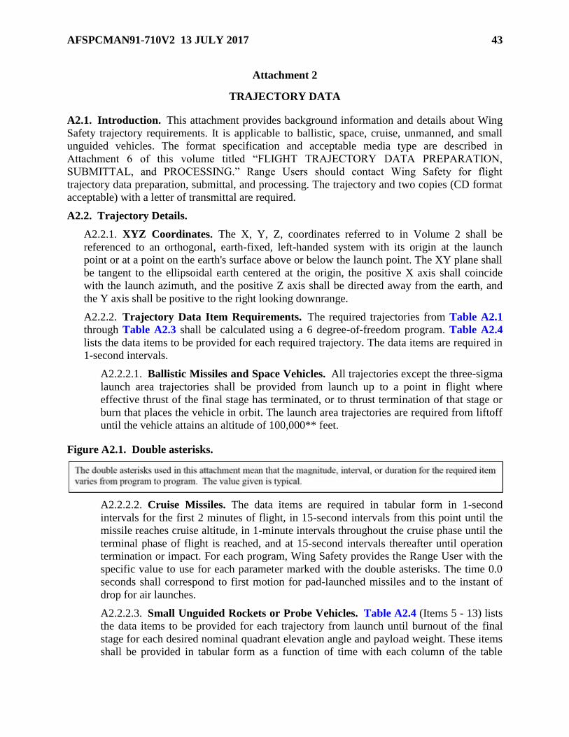
AFSPCMAN91-710V2 13 JULY 2017 43
Attachment 2
TRAJECTORY DATA
A2.1. Introduction. This attachment provides background information and details about Wing
Safety trajectory requirements. It is applicable to ballistic, space, cruise, unmanned, and small
unguided vehicles. The format specification and acceptable media type are described in
Attachment 6 of this volume titled “FLIGHT TRAJECTORY DATA PREPARATION,
SUBMITTAL, and PROCESSING.” Range Users should contact Wing Safety for flight
trajectory data preparation, submittal, and processing. The trajectory and two copies (CD format
acceptable) with a letter of transmittal are required.
A2.2. Trajectory Details.
A2.2.1. XYZ Coordinates. The X, Y, Z, coordinates referred to in Volume 2 shall be
referenced to an orthogonal, earth-fixed, left-handed system with its origin at the launch
point or at a point on the earth's surface above or below the launch point. The XY plane shall
be tangent to the ellipsoidal earth centered at the origin, the positive X axis shall coincide
with the launch azimuth, and the positive Z axis shall be directed away from the earth, and
the Y axis shall be positive to the right looking downrange.
A2.2.2. Trajectory Data Item Requirements. The required trajectories from Table A2.1
through Table A2.3 shall be calculated using a 6 degree-of-freedom program. Table A2.4
lists the data items to be provided for each required trajectory. The data items are required in
1-second intervals.
A2.2.2.1. Ballistic Missiles and Space Vehicles. All trajectories except the three-sigma
launch area trajectories shall be provided from launch up to a point in flight where
effective thrust of the final stage has terminated, or to thrust termination of that stage or
burn that places the vehicle in orbit. The launch area trajectories are required from liftoff
until the vehicle attains an altitude of 100,000** feet.
Figure A2.1. Double asterisks.
A2.2.2.2. Cruise Missiles. The data items are required in tabular form in 1-second
intervals for the first 2 minutes of flight, in 15-second intervals from this point until the
missile reaches cruise altitude, in 1-minute intervals throughout the cruise phase until the
terminal phase of flight is reached, and at 15-second intervals thereafter until operation
termination or impact. For each program, Wing Safety provides the Range User with the
specific value to use for each parameter marked with the double asterisks. The time 0.0
seconds shall correspond to first motion for pad-launched missiles and to the instant of
drop for air launches.
A2.2.2.3. Small Unguided Rockets or Probe Vehicles. Table A2.4 (Items 5 - 13) lists
the data items to be provided for each trajectory from launch until burnout of the final
stage for each desired nominal quadrant elevation angle and payload weight. These items
shall be provided in tabular form as a function of time with each column of the table

44 AFSPCMAN91-710V2 13 JULY 2017
containing only a single parameter. Time shall be given at even intervals, not to exceed 1-
second increments during thrusting flight, and for times corresponding to ignition, thrust
termination or burnout, and separation of each stage. If stage burning times are less than
4 seconds, time intervals should be reduced to 0.2 seconds or less.
A2.2.3. Nominal (Reference) Trajectory. The nominal or reference trajectory is the
trajectory that the vehicle would fly if all vehicle parameters were exactly as expected, if all
vehicle systems performed exactly as planned, and there were no external perturbing
influences.
A2.2.4. Three-Sigma Dispersed Trajectories. The three-sigma dispersed trajectories
define the downrange and cross-range limits of normality for the vehicle IIP at any time after
launch. The three-sigma trajectories shall be computed using annual wind profiles unless the
launch is to be conducted at a particular time of the year and only at that time. Care should be
exercised in the selection of the cumulative percentage frequency of the wind profile used for
the computation of these trajectories. Selecting a wind profile as severe as the worst wind
conditions when a launch would be attempted is usually recommended. In critical instances,
this has the disadvantage of limiting the allowable launch azimuth or reducing the allowable
launch day winds in the flight safety restrictions for wind drift of vehicle fragments resulting
from FTS action. The flight termination criteria allow for as much vehicle deviation due to
wind as shown in these trajectories, but does not account for wind conditions that exceed
those used in these computations.

AFSPCMAN91-710V2 13 JULY 2017 45
Table A2.1. Trajectory Types for Single Flight Azimuths.
Item # Program Trajectory Type Reference
1 All Programs Nominal or reference A2.2.3.
2 Ballistic Missiles
and Space
Vehicles
Three-sigma maximum-performance A2.2.4.2.
3 Three-sigma minimum-performance A2.2.4.2.
4 Three-sigma lateral left A2.2.4.3.
5 Three-sigma lateral right A2.2.4.3.
6 Three-sigma steep launch area A2.2.4.4.
7 Three-sigma lateral launch area A2.2.4.4.
8 Fuel-exhaustion A2.2.4.5.
9 Cruise Missile Three-sigma maximum-altitude. The
maximum altitude deviations (feet) above
nominal as a function of ground range from
the launch or drop point may be substituted
for Table A2.4., Item 3.
A2.2.4.2.
A2.2.4.2.1.
10 Three-sigma minimum-altitude. The
maximum altitude deviations (feet) below
nominal as a function of ground range from
the launch or drop point may be substituted
for Table A2.4., Item 3.
A2.2.4.2.
A2.2.4.2.1.
11 Three-sigma lateral. The maximum lateral
deviations (feet or nautical miles) from the
nominal flight path as a function of ground
range from the launch or drop point may be
substituted for Table A2.4., Item 3.
A2.2.4.3.
A2.2.4.3.4.
12 Fuel-exhaustion. The three-sigma high
performance trajectory should define the
vehicle capability limits in climbing to the
maximum altitude at the maximum possible
rate. Table A2.4., Items 3 & 4 are required
from launch or drop until the vehicle reaches
a steady-state cruise condition.
A2.2.4.5.
A2.2.4.5.1.

46 AFSPCMAN91-710V2 13 JULY 2017
Table A2.2. Trajectory Types for Variable Flight Azimuths.
Item # Trajectory Type Reference
1 Nominal, reference, central, or middle trajectory A2.2.3.
2 Extreme right-hand nominal or steepest nominal trajectory A2.2.3.
3 Extreme left-hand nominal or shallowest nominal trajectory A2.2.3.
4 Three-sigma maximum-performance trajectory for the centrally
located flight azimuth
A2.2.4.2.
5 Three-sigma minimum-performance trajectory for the centrally
located flight azimuth
A2.2.4.2.
6 Three-sigma lateral trajectories for the centrally located flight
azimuth
A2.2.4.3.
7 Three-sigma left for smallest flight azimuth A2.2.4.2.
8 Three-sigma right for largest flight azimuth A2.2.4.2.
9 Three-sigma steep launch area A2.2.4.4.
10 Three-sigma lateral launch area A2.2.4.3.
11 Fuel-exhaustion A2.2.4.5.
Table A2.3. Trajectory Types for Multiple Liquid Propellant Engines Thrusting at Liftoff.
Item # Trajectory Type Reference
1 Three-sigma steep launch area trajectory with one or more engines
not thrusting
A2.2.4.4.
2 Three-sigma lateral launch area trajectory with one or more engines
not thrusting
A2.2.4.3.
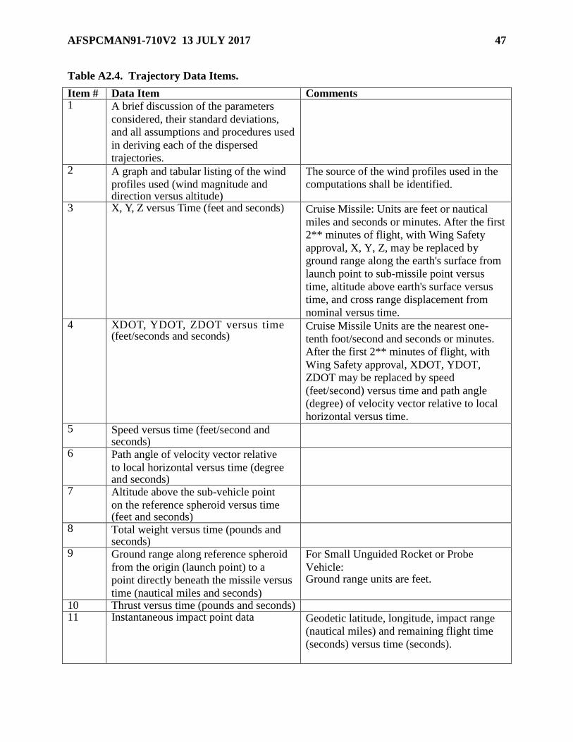
AFSPCMAN91-710V2 13 JULY 2017 47
Table A2.4. Trajectory Data Items.
Item # Data Item Comments 1 A brief discussion of the parameters
considered, their standard deviations,
and all assumptions and procedures used
in deriving each of the dispersed
trajectories.
2 A graph and tabular listing of the wind
profiles used (wind magnitude and direction versus altitude)
The source of the wind profiles used in the
computations shall be identified.
3 X, Y, Z versus Time (feet and seconds) Cruise Missile: Units are feet or nautical
miles and seconds or minutes. After the first
2** minutes of flight, with Wing Safety
approval, X, Y, Z, may be replaced by
ground range along the earth's surface from
launch point to sub-missile point versus
time, altitude above earth's surface versus
time, and cross range displacement from
nominal versus time. 4 XDOT, YDOT, ZDOT versus time
(feet/seconds and seconds) Cruise Missile Units are the nearest one-
tenth foot/second and seconds or minutes.
After the first 2** minutes of flight, with
Wing Safety approval, XDOT, YDOT,
ZDOT may be replaced by speed
(feet/second) versus time and path angle
(degree) of velocity vector relative to local
horizontal versus time. 5 Speed versus time (feet/second and
seconds)
6 Path angle of velocity vector relative
to local horizontal versus time (degree and seconds)
7 Altitude above the sub-vehicle point
on the reference spheroid versus time (feet and seconds)
8 Total weight versus time (pounds and seconds)
9 Ground range along reference spheroid
from the origin (launch point) to a
point directly beneath the missile versus
time (nautical miles and seconds)
For Small Unguided Rocket or Probe
Vehicle: Ground range units are feet.
10 Thrust versus time (pounds and seconds) 11 Instantaneous impact point data Geodetic latitude, longitude, impact range
(nautical miles) and remaining flight time
(seconds) versus time (seconds).

48 AFSPCMAN91-710V2 13 JULY 2017
12 Launch azimuth Degrees measured clockwise from true North.
13 The name, coordinates, and mean sea
level elevation of the coordinate system
origin (launch pad).
14 Name of reference spheroid used in
trajectory calculations.
A2.2.4.1. Generating a Single Composite Three-Sigma Trajectory. To generate a
single composite three-sigma trajectory in terms of instantaneous impact range, the
following procedure is suggested. If the following procedure is not used, a description of
the method used to generate the three-sigma trajectories shall be provided.
A2.2.4.1.1. Step 1: Identify individual parameters such as thrust, weight, specific
impulse, and atmospheric density that significantly affect the performance of the
vehicle IIP. Estimate three-sigma dispersions for these parameters.
A2.2.4.1.2. Step 2: Run a series of trajectory computations or simulations where
three-sigma values of significant perturbing parameters are introduced one at a time.
At a suitable number of time points, tabulate the IIP deviations from nominal that
have been caused by perturbing each parameter.
A2.2.4.1.3. Step 3: At each time point and direction, calculate the square root of the
sum of the squares of all deviations to arrive at the three-sigma IIP deviations.
A2.2.4.1.4. Step 4: By further trajectory computations or simulations, generate a
thrusting flight trajectory (a three-sigma, no-wind trajectory) that matches as closely
as possible the three-sigma deviations calculated in Step 3. This may be done by
perturbing only a few key parameters at varying magnitudes throughout the run.
A2.2.4.1.5. Step 5: Compute the required three-sigma trajectory using worst case
winds together with the parameter magnitudes used to calculate the three-sigma, no-
wind trajectory. The wind dispersed trajectories indicate vehicle performance
deviations due to the effects of severe winds. This data should be supplied until the
vehicle attains an altitude where there is essentially no wind effect. It is usually
sufficient to use 100,000 feet as this altitude limit. Computations should not be
limited to wind drift but include all wind effects.
A2.2.4.2. Three-Sigma Maximum and Minimum Performance Trajectories. The
three-sigma maximum and three-sigma minimum-performance trajectories define at any
time after launch the limits of normality as far as impact downrange is concerned. The
three-sigma maximum-performance trajectory provides the maximum downrange
distance of the vacuum IIP for any given time and the three-sigma minimum-performance
trajectory provides the minimum downrange distance of the IIP for any time. In
calculating these trajectories, head and tail wind profiles should be used that represent the
worst wind conditions for which a launch would be attempted. For any particular time
after launch, approximately 99.73 percent of all normal vehicles (assuming a normal
Gaussian distribution) that are subjected to the assumed wind will have impact ranges
lying between the extremes, achieved at that time by three-sigma maximum performance
and three-sigma minimum-performance vehicles. Of the 0.27 percent of the normal

AFSPCMAN91-710V2 13 JULY 2017 49
vehicles that fall outside the three-sigma limits, approximately half would be short and
half would be long. It is recognized that it may not be possible for a normally performing,
fully guided vehicle to fly either the three-sigma maximum or minimum-performance
trajectory as defined above. However, what is wanted is a single trajectory having an
impact range at any time greater than the impact range of 99.865 percent of all normal
vehicles, and a single trajectory with an impact range at any time less than the impact
range of 99.865 percent of all normal vehicles. Any deviation out- side of three-sigma
limits indicates that the vehicle is probably behaving in an abnormal, though not
necessarily dangerous, fashion. Those parameters having a significant effect upon impact
range, such as thrust, specific impulse, weight, variation in firing times of different
stages, and fuel flow rates, should be combined in the best considered fashion to produce
the required results.
A2.2.4.2.1. Cruise Missiles. The three-sigma high performance trajectory should
define the vehicle capability limits in climbing to maximum altitude at the maximum
possible rate. It defines, at any time after launch, the limits of normality as far as
impact range is concerned. The three-sigma high-performance trajectory provides the
maximum downrange distance of the vacuum instantaneous impact point (IIP) for any
given time. The three-sigma maximum and minimum-altitude trajectories define for
any ground range the limits of normality as far as altitude is concerned. In other
words, for any particular ground range approximately 99.73 percent of all normal
vehicles (assuming a normal Gaussian distribution) will have altitudes between the
extremes defined by three-sigma maximum altitude and three-sigma minimum-
altitude trajectories. Any deviation outside these limits indicates that the vehicle is
behaving in an abnormal, though not necessarily dangerous, fashion. However, the
Mission Flight Control Officer (MFCO) may destroy such a vehicle if it is
approaching land or threatening to get outside or below the command destruct
coverage area.
A2.2.4.3. Three-Sigma Lateral Trajectory Requirements.
A2.2.4.3.1. Definition. Three-sigma lateral trajectories define the cross-range limits
of normality for the vacuum instantaneous impact point (IIP). Both a three-sigma left
and a three-sigma right trajectory shall be provided. These trajectories should be
calculated using the worst lateral wind conditions for which a launch would be
attempted. For any downrange distance, the IIP traces for 99.73 percent of all normal
vehicles subjected to the assumed winds lie between the three-sigma lateral IIP traces.
For variable azimuth launches, a three-sigma left trajectory for the smallest flight
azimuth in the approved azimuth sector and a three-sigma right trajectory for the
largest flight azimuth in the approved sector are required in addition to three-sigma
lateral trajectories for a centrally located flight azimuth. Unless the procedure is
invalid, the assumption will be made that the three-sigma left and right trajectories
provided for the centrally located azimuth can be used to produce a reasonable
approximation of the three-sigma left and right trajectories for other flight azimuths
by reorienting the X and Y axis of the data. For example, if the three-sigma lateral
trajectories have been computed for a central flight azimuth of 100 degrees, the three-
sigma lateral trajectories for a 90-degrees flight azimuth will be determined simply by
assuming that the X axis is 90 degrees instead of 100 degrees. If this assumption is
50 AFSPCMAN91-710V2 13 JULY 2017
not reasonable, additional trajectories shall be provided to define the extreme left and
right lateral limits.
A2.2.4.3.2. Use. Three-sigma lateral trajectories are needed to determine whether a
normal vehicle experiencing a three-sigma deviation will violate flight safety destruct
criteria. They may also be used as guidelines by the MFCO in deciding whether a
vehicle will be allowed to continue in flight or to over fly land. When used for
comparison with the impact predictor destruct criteria, the vacuum IIP data are
required. When used on the present-position display, values of X, Y, Z along the
three-sigma lateral trajectories are required. The three-sigma lateral trajectories, as
defined in A2.2.4.3.1. in terms of IIP, may not provide three-sigma deviations of the
lateral position Y as a function of X, although this is normally assumed to be the case.
If this assumption is not valid, the Range User should also submit three-sigma
trajectories that define the lateral limits of Y in terms of X.
A2.2.4.3.3. Calculation. In calculating a three-sigma lateral trajectory, those
parameters having a significant effect on the lateral deviation of the IIP (or of the
position Y in terms of X) should be combined in the best considered fashion to
produce the required results. The procedures described in A2.2.4.2. and A2.2.4.2.1.
for calculating three-sigma maximum and minimum-performance trajectories are also
suggested here.
A2.2.4.3.4. Cruise Missiles. The three-sigma lateral trajectory defines the lateral
limits within which 99.73 percent of all normal missiles are expected to remain. This
trajectory should be calculated using the worst lateral wind condition for which a
launching would be attempted. Since only one three-sigma lateral trajectory is
requested, the assumption will be made that the three-sigma left and three-sigma right
trajectories are symmetric about the nominal trajectory. If this assumption is not
reasonable, then both three-sigma left and three-sigma right trajectories shall be
provided. A missile that deviates outside the three-sigma lateral limits is subject to
possible destruction if it is approaching land or threatening to get outside or below the
command destruct coverage area.
A2.2.4.4. Dispersed Launch Area Trajectories. If the dispersed launch area
trajectories are computed as specified and the proposed flight plan is approved, the
launch agency can be certain that a normal vehicle will not violate the safety destruct
criteria in the launch area, irrespective of the actual winds existing at launch.
Unfortunately, there is also a distinct disadvantage in using extreme winds to calculate
the dispersed trajectories. To arrive at destruct lines that will not be violated by vehicles
flying the extreme trajectories, the allowances made for wind effects in the destruct line
computations must be kept small. This, in turn, means that wind restrictions must be
imposed on launch day. The wind profile used in the destruct calculations may be much
smaller than the extreme wind profiles used to calculate the dispersed trajectories. In
general, the greater the wind profile used in calculating the dispersed launch area
trajectories, the steeper the trajectories are; and the steeper the dispersed trajectories, the
more severe the Launch Safety wind restriction must be on launch day to have acceptable
destruct criteria. Reducing the wind profile in calculating the dispersed trajectories
lessens the probability of a hold due to wind, but increases the probability that a normal
vehicle will fly outside the limits defined by the dispersed trajectories. This, in turn,
AFSPCMAN91-710V2 13 JULY 2017 51
increases the probability that a normal vehicle will be destroyed. For those vehicle flights
for which severe launch area wind restrictions are required, it may be necessary for the
Range User to supply dispersed launch area trajectories for two or three different wind
profiles. By so doing, the probability of a safety hold due to wind is thus reduced.
A2.2.4.4.1. Three-Sigma Steep Launch Area Trajectory. The three-sigma steep
launch area trajectory should maximize Z as a function of X', where the azimuth of
the X' axis must be specified by Wing Safety for each program or group of similar
flights. The positive X' axis is directed downrange from the launch point directly
away from the uprange impact limit line so the negative X' axis intersects the impact
limit line at right angles. In calculating this trajectory a head wind (or tail wind)
blowing toward (or away from) the impact limit line, that is, blowing from (or
toward) the positive X' direction, normally is used. This wind profile should, but may
not always, represent the worst conditions for which a launch would be attempted.
Therefore, other wind azimuths may need to be examined for worst conditions
depending on the particular vehicle’s guidance system response to wind direction. If
other perturbing factors such as gyro drift or high thrust add significantly to the
uprange deviations caused by wind, these factors should also be included in the
calculations. The steep launch area trajectory is a three-sigma trajectory in that, for
any X', the value of Z along the three-sigma steepest trajectory would be greater than
the corresponding values of Z achieved by 99.865 percent of all normal missiles
subjected to the assumed head wind.
A2.2.4.4.2. Three-Sigma Lateral Launch Area Trajectory. The three-sigma
lateral launch area trajectory should maximize Z as a function of Y', where the
azimuth of the Y' axis must be specified by the Flight Analysis Section for each
program or group of similar flights. When looking down-range, the negative Y' axis is
laterally directed to the right with respect to the intended flight line, the actual
direction being perpendicular to the lateral impact limit line being protected. In
calculating this trajectory, a lateral wind blowing toward (or away from) the impact
limit line, that is, blowing from (or toward) the positive Y' direction normally is used.
This wind profile should, but may not always, represent the worst conditions for
which a launch would be attempted. Therefore, other wind azimuths may need to be
examined for worst conditions depending on the particular vehicle’s guidance system
response to wind direction. Other perturbing factors that add significantly to the
vehicle lateral movement, such as gyro drift, roll program error, and alignment errors,
should also be included in the calculations. The lateral launch area trajectory is a
three-sigma trajectory in that, for any Y', the value of Z along the three-sigma lateral
launch area trajectory would be greater than the corresponding values of Z achieved
by 99.865 percent of all normal missiles subjected to the assumed lateral wind.
A2.2.4.5. Fuel-Exhaustion Trajectory. For many flights, a programmed thrust
termination may be scheduled well in advance of fuel exhaustion. To know whether a
potential safety problem can arise if the vehicle should fail to cut off, trajectory data
through fuel exhaustion are needed. For ballistic missile flights, the information should
be provided only for the last stage IAW assumptions mutually agreed to by the Range
User and Wing Safety. For orbital flights, the fuel exhaustion trajectory should be
provided for the last suborbital stage. The requirement should be met by extending either

52 AFSPCMAN91-710V2 13 JULY 2017
the nominal or three-sigma maximum-performance trajectory through fuel exhaustion,
depending on which produces a greater impact range.
A2.2.4.5.1. Cruise Missiles. In calculating this trajectory, a tail-wind profile should
be used that represents the worst wind conditions for which a launching would be
attempted. For any particular time after launch, approximately 99.73 percent of all
normal vehicles (assuming a normal Gaussian distribution) will have impact ranges
less than the range achieved at that time by a three-sigma high performance mission.

AFSPCMAN91-710V2 13 JULY 2017 53
Attachment 3
MALFUNCTION TURN DATA
A3.1. Introduction. This attachment provides background information and details about Wing
Safety malfunction turn data requirements. It is applicable to ballistic missiles, space vehicles,
cruise missiles. The turn data shall describe the turning capability of the vehicle velocity vector
as a function of thrust vector offset or other parameters characterizing the turns. This information
is used to determine how fast a vehicle or, more exactly, a vehicle impact point can deviate from
the nominal if a malfunction occurs. Velocity vector turn data is required only for the thrusting
periods from launch up to a point in flight where effective thrust of the final stage has terminated
or to thrust termination of that stage or burn that places the vehicle in orbit.
A3.2. Turn Definitions.
A3.2.1. Yaw turn – the angle turned in the lateral direction by the total velocity vector. The
lateral plane is defined as the plane normal to the vector generated by the cross-product of
the unit vectors of the total velocity and the normal to the nominal trajectory plane, not the
angle turned in the horizontal plane by the horizontal component.
A3.2.2. Maximum turn capability – the envelope of the maximum-rate trim and all tumble
velocity vector turn angle curves for a given malfunction time, irrespective of how unlikely
this rate is to occur.
A3.2.3. Trim turn – a turn resulting from a malfunction that causes the launch vehicle thrust
moment to balance the aerodynamic moment while imparting a constant rotation rate to the
vehicle longitudinal axis. The maximum-rate trim turn is the trim turn made at or near the
greatest angle of attack that can be maintained while the aerodynamic moment is just
balanced by the thrust moment, whether the vehicle is stable or unstable.
A3.2.4. Tumble turn – the family of tumble turns that results if the airframe rotates in an
uncontrolled fashion at various angular rates, each rate being brought about by a different,
constant value of the thrust vector offset angle or constant value of another parameter that
defines the tumble turn.
A3.2.5. 90-degree option – the turn produced by directing and maintaining the vehicle thrust
at about 90 degrees to the velocity vector without regard for how this situation can be
brought about.
A3.2.6. Turn Angle Envelope – the maximum turn angle curve created by selecting the
points from a variety of individual engine deflection curves that provide maximum turn angle
for the shortest malfunction duration. The associated velocity curve will be derived by
selecting the velocity that physically corresponds to the final maximum turn angle curve.
A3.2.7. Turn Curve – Simplified data format used to represent the malfunction turn in terms
of how the velocity vector magnitude and direction in a plane changes with time.
A3.2.8. Turn Trajectories – Data format that represents numerous malfunction turn
simulations in a standard trajectory format.

54 AFSPCMAN91-710V2 13 JULY 2017
A3.3. Malfunction Turn Computation Requirements:
A3.3.1. Turning information need be computed for the nominal or reference trajectory only.
A3.3.2. In the various velocity vector turn computations, it should be assumed that the
vehicle performance is normal up to the point of the malfunction that produces the turn.
A3.3.3. If turn curve data is to be provided, the effects of gravity shall be omitted from the
final turn data calculations.
A3.3.4. If pitch and yaw turn angles are essentially the same except for the effects of gravity,
the yaw turn angles may be determined from pitch calculations that, in effect, have had the
gravity component subtracted out at each step in the computations.
Figure A3.1. Double asterisks.
A3.3.5. During the first 100** seconds of flight both pitch and yaw turns shall be provided.
After 100** seconds, turns need be computed only in the yaw plane. For each program, Wing
Safety provides the Range User with the specific value to use for each parameter marked
with the double asterisks. Exception: During the first 100** seconds of flight, when
neglecting gravity, if the pitch and yaw turns are the same, only the yaw turns are required.
A3.3.6. Malfunction turn data are required for malfunctions initiated at even 4** second
intervals beginning 4** seconds after first motion continuing for the first 100** seconds of
flight or through the first-stage thrusting phase and into the second-stage phase for at least
one time point, and at even 8** second intervals thereafter.
A3.3.7. One possible difficulty needs to be mentioned in connection with calculating tumble
turns for aerodynamically unstable missiles. In the high aerodynamic region, it often turns
out that no matter how small the initial deflection of the rocket engine, the airframe tumbles
through 180 degrees or one-half cycle in less than the specified time period for which the
calculations are to be carried out. In such a case, if the computation is carried out for the
specified time period, part of the angle turned by the velocity vector during the first half
cycle is then canceled out during the second half cycle of the turn. If only tumble turns were
considered in such cases, the conclusion would be reached that the vehicle velocity vector
can turn through a greater angle in a shorter time period than it can in a longer time period.
This is an unacceptable conclusion from a safety viewpoint. The envelope of the family of
tumble turns must rise continuously throughout the specified malfunction time period. One
generally acceptable way to satisfy this requirement is to compute tumble turn angles without
considering aerodynamic forces. Although such a vacuum turn cannot actually be simulated
in the atmosphere by means of a constant engine deflection, in all likelihood there is some
particular intelligent behavior of the engine that can approximate the turn fairly closely. If,
however, vacuum tumble turns are considered unrealistic and unjustifiable, other types of
malfunctions shall be considered.
AFSPCMAN91-710V2 13 JULY 2017 55
A3.3.8. The turn data shall be defined for a series of malfunction modes such as thrust vector
offset. Turn data computations shall include a credible distribution (range) of parameter
values to demonstrate the variation of the turn characteristics caused by each malfunction
mode. If the turns can occur as a function of more than one malfunction mode (for example,
solid rocket motor (SRM) thrust vector offset angle for thrust vector control failures and
thrust dissipation time for SRM nozzle burn through), turn data are required for each mode.
Where possible, the same set of malfunction modes shall be used for each turn initiation
time.
A3.4. Malfunction Turns off of Guidance and Performance Dispersed
Trajectories. Although velocity vector turning computations are not required for the three-
sigma maximum and three-sigma minimum performance trajectories, a method for applying the
turn angles to these trajectories shall be provided. The trajectory data items of A2.2.2. shall also
be applied for the trajectory used to start the turn computations, if this trajectory is not one of
those provided in response to A2.2.1. Range Users should contact Wing Safety regarding data
format requirements. A columnar or block printout is acceptable. In addition, a complete
discussion is required of assumptions made, methods of calculation, and equations used in
deriving the malfunction turns.
A3.5. Determining Types of Data to Submit. In determining the maximum turn capability of
a vehicle, the usual procedure is for the Range User to consider both trim turns and tumble turns,
in both the pitch and yaw planes. However, with Wing Safety approval, the Range User may
elect to calculate turn rates using the 90-degree option in lieu of trim and tumble turns. If the 90-
degree option is ruled out, the criteria for each of the vehicle conditions listed in A3.5.2. through
A3.5.4. should be used to determine whether trim turns, tumble turns, or both should be provided
at each turn initiation time. For determining the format (of turn curves vs turn trajectories) to
deliver refer to A3.5.5. Note that A3.5.5. is a new requirement that will be defined in a
subsequent comment.
A3.5.1. 90 Degree Option. In some cases, Wing Safety may accept turning angles or rates
computed on the basis of the 90-degree assumption even though it is extremely unlikely for
the missile to achieve these turn rates. This option is usually quite disadvantageous to the
Range User, since larger turning angles (higher turn rates) lead to more restrictive destruct
criteria. Such unduly restrictive criteria could necessitate the revision of a proposed flight
plan that may otherwise have been allowed or could result in somewhat earlier destruction of
an erratic missile.
A3.5.2. Condition 1: For Vehicles Aerodynamically Unstable at All Angles of Attack.
During that part of flight where the maximum trim angle of attack is small, it may be obvious
that tumble turns lead to greater turning angles. If the maximum trim angle of attack is large,
trim turns will in all probability lead to higher turning angles than tumble turns and to more
restrictive destruct criteria.
A3.5.2.1. If the Range User can state that the probability of flying a trim turn even for a
period of only a few seconds is virtually zero, only tumble turns are required.
A3.5.2.2. If the Range User cannot so state, a series of trim turns (that includes the
maximum-rate trim turn) and the family of tumble turns shall be provided.
A3.5.3. Condition 2: For Vehicles Stable at All Angles of Attack.

56 AFSPCMAN91-710V2 13 JULY 2017
A3.5.3.1. If the vehicle is so stable that the maximum thrust moment cannot produce
tumbling, but produces a maximum-rate trim turn at some angle of attack less than 90
degrees, a series of trim turns that includes the maximum-rate trim turn shall be provided.
A3.5.3.2. If the maximum thrust moment results in a maximum-rate trim turn at some
angle of attack greater than 90 degrees, a series of trim turns shall be provided only for
angles of attack up to and including 90 degrees.
A3.5.4. Condition 3: For Vehicles Unstable at Low Angles of Attack but Stable at Some
Higher Angle of Attack Region:
A3.5.4.1. If large engine deflections result in tumbling, whereas small engine deflections
do not, a series of trim and tumble turns should be generated as prescribed in A3.5.2. for
aerodynamically unstable missiles. The same difficulty discussed in A3.3.5. with tumble
turns may arise here; namely, the envelope of the computed tumble turns may fail to rise
continuously throughout the entire time period for which the calculations are to be carried
out. In this event, either tumble-turn calculations neglecting aerodynamic forces or trim-
turn calculations must be made as discussed in A3.5.2.
A3.5.4.2. If both large and small constant engine deflections result in tumbling,
irrespective of how small the deflection might be, the turn data achieved at the stability
angle of attack, assuming no upsetting thrust moment, are required in addition to the turn
data achieved by a tumbling vehicle. This situation arises because the stability at high
angles of attack is insufficient to arrest the angular velocity that is built up during the
initial part of a tumble turn where the vehicle is unstable. Although the missile cannot
arrive at this stability angle of attack as a result of the constant engine deflection, there is
some deflection behavior that will produce this result. If arriving at such a deflection
program is too difficult or too time consuming, it may be assumed that the vehicle
somehow instantaneously rotated to the trim angle of attack and stabilizes at this point. If
so, tumble turn angles may be used in Wing Safety destruct calculations during that part
of flight for which the envelope rises continuously for the duration of the computation.
A3.5.5. For vehicles thrusting during a nominal high velocity and high angle of attack
portion of flight, or vehicles that have large thrust vector(s) offset away from the center of
gravity, or vehicles that have large aerodynamic moments not typical of a standard launch
vehicle.
A3.5.5.1. Turn curve data becomes hard to apply for Wing Safety assessments. For
phases of flight where nominal angle of attack is high or the vehicle has asymmetry,
many (100s to 1000s) simulated turn trajectories are required per failure time. Turn
trajectories should contain multiple thrust vector offsets in multiple turn planes per failure
time. Additionally, each turn trajectory should initiate from a randomly selected
trajectory within the family of guidance and performance trajectories. Malfunction turn
trajectories should follow the data format and data items specified in A6.3.7. and
requirements in A3.3. and A3.6.

AFSPCMAN91-710V2 13 JULY 2017 57
A3.6. Turn Duration. The malfunction turn data (turn curves or turn trajectories) are to be
provided at 1** second intervals, for at least 12** seconds into the turn and until one of the
following two conditions are met. Various time intervals or time delays shall be considered,
since the delays that are built into the Wing Safety destruct calculations depend upon the
accuracy, sensitivity, and type of presentation associated with a particular instrumentation
system as well as missile characteristics.
A3.6.1. The vehicle reaches a critical loading condition that will cause breakup.
A3.6.2. The vehicle is tumbling so rapidly that the effective thrust acceleration is negligible;
for example, the projected vacuum impact point is no longer moving significantly.
A3.7. Turn Curve Data Format. Malfunction turn data shall be delivered in the form of
graphs and digital data files. Scale factors of plots shall be selected so the plotting and reading
accuracies do not degrade the basic accuracy of the data. In addition, tabular listings of the data
used to generate the graphs are required in ASCII format files on floppy or compact disks or
other electronic media, with corresponding hard copies. The 5 data files required shall provide
textual information about the files, time and thrust information, the maximum turn envelope of
the family of curves, associated velocities for this envelope, and special time points for the
family of curves presented in the graphs.
A3.7.1. Velocity Turn Angle Graphs. For turn angle graphs, the ordinate represents the
total angle turned by the velocity vector in degrees; and the abscissa, the time duration of the
turn in seconds.
A3.7.2. Velocity Magnitude Graphs. For velocity magnitude graphs, the ordinate
represents the magnitude of the velocity vector in feet per second; and the abscissa, the time
duration of the turn in seconds.
A3.7.3. Digital Data Files. The required data consists of five data files. Data units shall be
in the English system. Files 2 through 5 shall contain related data and must have the same
number of records. Each record in an individual file should have the same number of words.
Each line of the records in File 3 – 5 shall contain 6 words (suggested format is 6E20.12).
File contents shall be as follows:
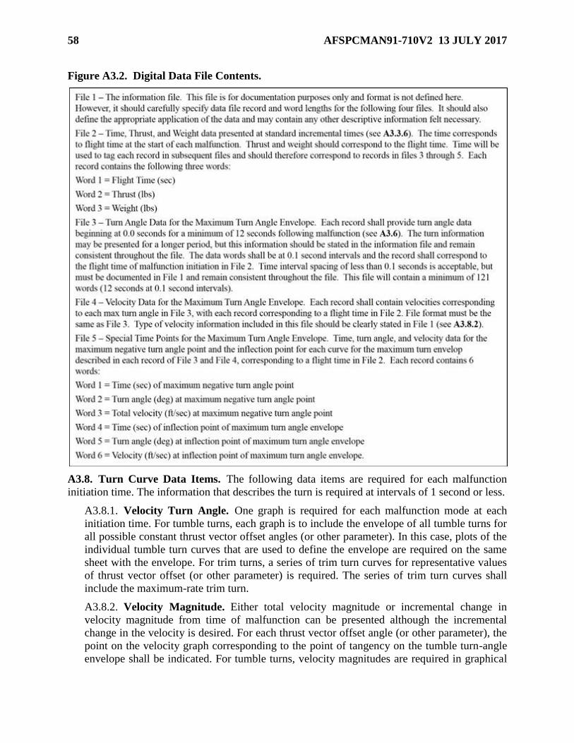
58 AFSPCMAN91-710V2 13 JULY 2017
Figure A3.2. Digital Data File Contents.
A3.8. Turn Curve Data Items. The following data items are required for each malfunction
initiation time. The information that describes the turn is required at intervals of 1 second or less.
A3.8.1. Velocity Turn Angle. One graph is required for each malfunction mode at each
initiation time. For tumble turns, each graph is to include the envelope of all tumble turns for
all possible constant thrust vector offset angles (or other parameter). In this case, plots of the
individual tumble turn curves that are used to define the envelope are required on the same
sheet with the envelope. For trim turns, a series of trim turn curves for representative values
of thrust vector offset (or other parameter) is required. The series of trim turn curves shall
include the maximum-rate trim turn.
A3.8.2. Velocity Magnitude. Either total velocity magnitude or incremental change in
velocity magnitude from time of malfunction can be presented although the incremental
change in the velocity is desired. For each thrust vector offset angle (or other parameter), the
point on the velocity graph corresponding to the point of tangency on the tumble turn-angle
envelope shall be indicated. For tumble turns, velocity magnitudes are required in graphical

AFSPCMAN91-710V2 13 JULY 2017 59
form as a function of time for each thrust vector offset (or other parameter) used to define the
tumble turn envelope.
A3.8.3. Vehicle Orientation. If the vehicle has thrust augmenting rocket motors, then the
vehicle attitude (in the form of the angular orientation of the vehicle longitudinal axis) as a
function of time into the turn is required for each turn initiation time.
A3.8.4. Onset Conditions. The vehicle state at the beginning of the turn, including the
thrust, weight, and state vector (including velocity magnitude) shall be provided for each set
of curves.
A3.8.5. Breakup Information. The Range User shall specify if the vehicle will remain
intact throughout the turn. If the vehicle will breakup during a turn, then the point (time) for
which vehicle breakup is expected to occur shall be indicated. The time into the turn at which
vehicle breakup would occur can be a specific value or a probability distribution for time to
breakup.
A3.8.6. Probability of Occurrence. The distribution for the probability of occurrence for
the value of the parameter defining the turns, such as thrust vector offset, shall be defined for
each parameter (as a function of turn initiation time if the distribution varies with time). Also,
information defining how the probability distribution was determined shall be provided.
A3.9. Velocity Vector Turn Data for Cruise Missiles.
A3.9.1. From launch or drop until cruise altitude is reached, this information is required to
provide a means of determining the maximum angle through which the missile velocity
vector can turn in the event of a malfunction. The maximum angles turned for time intervals
up to about 30** seconds in duration are required. (The actual times will depend on the
delays included in the FTS as well as other factors). Both pitch and yaw turns should be
investigated and the larger presented. It should be assumed that the missile has followed the
nominal trajectory up to the point of malfunction that produces the maximum-rate trim turn.
Thereafter, it should be assumed that the missile is trimmed to the maximum air load that the
structure can stand, or that the missile is flying out of control in an attitude that produces
maximum lateral acceleration (for example, a near 90-degree bank with a maximum pitch
turn). During the launch phase, the missile may not be able to fly for 30** seconds under
these extreme conditions. In this event, it should be assumed that the missile is turning at the
maximum rate for which these flight conditions can be maintained for required time duration.
A complete discussion of the methods used in the calculations shall be provided. This
discussion should include assumptions made, types of malfunctions considered, forces
producing turns, equations used, and sample computations.
A3.9.2. During the cruise phase, the maximum turn capability of the velocity vector as a
function of altitude is required. Rates should be based on normal missile weights and the
expected cruising speeds at each altitude. For this phase of flight, the data may be expressed
in the form of maximum lateral accelerations, if desired. A complete discussion similar to
that requested for A3.9.1. is required. Also required is the maximum turn capability that the
guidance system and the autopilot can command during the cruise phase.

60 AFSPCMAN91-710V2 13 JULY 2017
A3.9.3. A cruise missile may be boosted from the launch pad by separable rockets or by a
booster motor that is an integral part of the missile. While the booster motor is thrusting, the
missile may perform more as a ballistic missile or space vehicle than as a cruise missile. In
such cases, maximum turning capability data during the boost phase will be required as
specified in A3.5. rather than as specified in A3.9.1. For each missile program, Wing Safety
shall indicate which procedures are to be used in computing malfunction turn data during the
boost phase.

AFSPCMAN91-710V2 13 JULY 2017 61
Attachment 4
FRAGMENT DATA
A4.1. Introduction. Fragment listings and characteristics for all potential modes of vehicle
breakup are required. At a minimum, the following modes of vehicle breakup shall be
considered: (1) breakup due to FTS activation, (2) breakup due to an explosion, and (3) breakup
due to aerodynamic loads, inertial loads, and atmospheric reentry heating. Fragment data is
required up to thrust termination of the last stage that carries a destruct system. All fragments of
0.5 lbm/sqft and greater, based on the minimum projected area, shall be included; and, as much
as possible (best estimate), all fragments down to a mass of 1.0 gram shall be included. Similar
fragments can be accounted for in fragment groups, however it is preferred that a list of each of
the individual fragments be provided.
A4.2. Describing Fragment Groups. A fragment group is one or more fragments whose
characteristics are similar enough to allow all the fragments to be described by a single
“average” set of characteristics. The following information is provided to aid in determining
fragment groups:
A4.2.1. Fragment Type. All fragments shall be of the same type (for example solid
propellant, explosive, or inert), including whether or not propellant fragments are burning
following breakup.
A4.2.2. Ballistic Coefficient (beta). The maximum beta in the group should be no more than
about a factor of 3 times the minimum (except for very low beta fragments where betas
ranging from near 0 to about 3 pounds per square foot [lb/ft2] can be grouped together).
A4.2.3. Weight. If the fragments contain propellant that is burning during free fall, the
maximum weight of propellant in a fragment group should be no more than a factor of 1.2
times the minimum weight of propellant. The fragments included in a group should be such
that the kinetic energies (KE) based on terminal velocity (KE = 13 x W x beta, foot pounds
force ft-lbf [The 13 has units of ft3/ lbf]) are within the following guidelines:
A4.2.3.1. Fragments having KE < 35 are grouped.
A4.2.3.2. Fragments having 35 < KE < 100 are grouped.
A4.2.3.3. Fragments having 100 < KE < 6,200 should be grouped so that the maximum
fragment KE is no more than about three times the minimum.
A4.2.3.4. Fragments having 6,200 < KE < 33,670 should be grouped so that the
maximum fragment KE is no more than about three times the minimum.
A4.2.3.5. Fragments having 33,670 < KE < 74,000 should be grouped so that the
maximum fragment KE is no more than about three times the minimum.
A4.2.3.6. Fragments having 74,000 < KE < 1,616,000 should be grouped so that the
maximum fragment KE is no more than about three times the minimum.
A4.2.3.7. Fragments having KE > 1,616,000 are grouped.
A4.2.4. Velocity Perturbation. The maximum expected destruct explosion or pressure
rupture induced velocity in the group should be no more than a factor of 1.2 times the
minimum induced velocity.
62 AFSPCMAN91-710V2 13 JULY 2017
A4.2.5. Projected Area. For explosive fragments, the range of projected areas should be
controlled by requiring that the maximum value of the weight of propellant at impact is no
more than a factor of two times the minimum; however, if the propellant is burning during
free fall the factor is 1.2. There is no limit on the range of projected areas for inert fragments.
A4.3. Fragment Data Items. These requirements provide a description of the data items
required for each fragment or fragment group for each potential mode of vehicle breakup. The
variation of the fragment characteristics with flight time shall be defined. Normally this is
accomplished by specifying multiple fragment lists, each of which is applicable over a specified
period of flight.
A4.3.1. That fragment that, in the absence of winds, is expected to travel a maximum
distance, and that fragment(s) that, in the absence of winds, is expected to travel a minimum
distance shall be included.
A4.3.2. Fragment group name.
A4.3.3. Number of fragments.
A4.3.4. General description(s) of fragments such as part/component, shape, dimensions, and
figure.
A4.3.5. Breakup Altitude. For breakup due to atmospheric reentry, the altitude at which
breakup is expected to occur shall be provided.
A4.3.6. Ballistic Coefficient (beta). Nominal, plus three-sigma, and minus three-sigma
values (psf) for each fragment or group; including graphs of the coefficient of drag (Cd)
versus Mach number for the nominal and three-sigma beta variations for each fragment or
group. Each graph shall be labeled with the shape represented by the curve and reference area
used to develop the curve. A Cd versus Mach curve for axial, transverse, and tumble
orientations (when applicable) shall be provided for fragments not expected to stabilize
during free-fall conditions. For fragments that may stabilize during free-fall, Cd versus Mach
curves should be provided for the stability angle of attack. If the angle of attack where the
fragment stabilizes is other than 0 degrees, both the coefficient of lift (CL) versus Mach
number and the Cd versus Mach number curves should be provided. If available, equations
for Cd versus Mach curves should be provided. The difficulty of estimating drag coefficient
curves and weights for vehicle pieces is fully realized. If this cannot be done satisfactorily, an
estimate of the subsonic and supersonic W/ Cd A for each major piece may be provided
instead. In either case, three-sigma tolerance limits shall be included for the drag coefficients
for the maximum and minimum-distance pieces.
A4.3.7. Weight per Fragment. Include the possible three-sigma weight (pounds) variation for
the fragment or group. The fragment data shall approximately add up to the total weight of
inert material in the vehicle plus the weight of contained liquid propellants and solid
propellant that is not consumed in the initial breakup and/or conflagration.
A4.3.8. Projected Area per Fragment (ft2). Include the axial, transverse, and tumbling area
for the fragment or group. This information is not required for those fragment groups classed
as uncontained propellant fragments (as described below).

AFSPCMAN91-710V2 13 JULY 2017 63
A4.3.9. Estimates of the maximum incremental velocities (feet/seconds) imparted to the
vehicle pieces due to FTS activation, explosive and/or overpressure loads at breakup. The
velocity is normally assumed to be Maxwellian distributed with the specified maximum
value equal to the 97th percentile. If the distribution is known to be significantly different
than the Maxwellian, the correct distribution is required, including if the specified value
should be interpreted as a fixed value with no uncertainty.
A4.3.10. Fragment Group Type.
A4.3.10.1. Type 1 = inert fragments; for example, no volatile type material that could be
burning or could explode.
A4.3.10.2. Type 2 = uncontained solid propellant fragments; for example, solid
propellant exposed directly to the atmosphere and will not explode upon impact.
A4.3.10.3. Type 3 = contained propellant fragments; for example, propellant that is
enclosed in a container, such as a motor case or pressure vessel, and will not explode
upon impact.
A4.3.10.4. Type 4 = contained explosive propellant fragments; for example, propellant
that is enclosed in a container, such as motor case or pressure vessel, and will explode
upon impact.
A4.3.10.5. Type 5 = uncontained explosive solid propellant fragments; for example,
solid propellant exposed directly to the atmosphere and will explode upon impact.
A4.3.11. Casualty Area per Fragment (ft2). The casualty area per fragment shall be based on
a fragment falling vertically at impact, and should reflect the credible fragment orientation
giving the maximum projected area.
A4.3.12. Vehicle stage where fragment group originated.
A4.3.13. For those fragment groups defined as uncontained propellant fragments, contained
propellant fragments, and explosive fragments, an indication as to whether or not the
propellant fragments are burning during free fall.
A4.3.14. For those fragment groups defined as contained propellant fragments, explosive or
non-explosive, the initial weight of contained propellant (pounds) and the consumption rate
during free fall (pounds per second); the initial weight of the propellant in a contained
propellant fragment is the weight of the propellant before and after the anomalous event.
A4.3.15. Diffusion and dispersion of any fragments containing toxic or radioactive materials
and the radiation and exposure characteristics.
A4.4. Residual Thrust Dispersion. If an upper stage can be ignited as a result of FTS
activation on a lower stage, sufficient information is required to evaluate the effects and duration
of thrust, and the maximum deviation of the impact point that can be brought about by this
thrust. The explosion effects on remaining fuels, pressurized tanks, and remaining stages are
required, particularly with respect to ignition or detonation of upper stages if destruct action is
64 AFSPCMAN91-710V2 13 JULY 2017
taken during the burning period of a lower stage. For each thrusting or non-thrusting stage
having residual thrust capability following FTS activation, provide either the total residual
impulse (pounds-seconds) imparted after "arm" and "destruct," or the full-residual thrust
(pounds-feet) versus time (s). Otherwise, a detailed analysis that clearly shows the stages are not
capable of thrusting after FTS activation is required.

AFSPCMAN91-710V2 13 JULY 2017 65
Attachment 5
JETTISONED BODY DATA
A5.1. General Data Requirements. The following data shall be provided for each jettisoned
body:
A5.1.1. The nominal impact point. The nominal impact point (or aiming point) for each
jettisoned body shall be given in terms of geodetic latitude and longitude in decimal degrees,
and range (nautical miles) from the pad. Computations shall be made for an ellipsoidal
rotating earth taking into account drag and, if applicable, lift.
A5.1.2. The number of fragments resulting from a specific scheduled jettison. If the
jettisoned body is expected to break up during reentry, an estimate of the number of pieces,
their approximate weights, cross-sectional areas, ballistic coefficients and their impact ranges
are required.
A5.1.3. Jettison flight time (seconds), total weight (pounds) jettisoned and weight per
fragment (pounds), reference area per fragment (ft2), and the best estimate of Cd versus Mach
number and sub-sonic and supersonic ballistic coefficient for each stage or piece. The Cd
versus Mach number data are to be provided in graphical and tabular format for the nominal,
minus three-sigma and plus three-sigma drag coefficients and shall cover the range of
possible Mach numbers from 0 to the maximum values expected during free fall. Also
indicate whether bodies are stable and, if so, at what angles of attack. For pieces that can
possibly stabilize during free flight, drag coefficient curves shall be provided for the stability
angle of attack. If the stability angle of attack is other than 0 degrees, both coefficient of lift
(CL) versus Mach number and Cd versus Mach number curves shall be provided. State briefly
how drag curves were determined.
A5.1.4. The three-sigma uprange-downrange (nautical miles) and crossrange (nautical miles)
impact dispersions and the azimuth orientation of the dispersion major axis (degrees
clockwise from true North), assuming a normally functioning vehicle. Three-sigma wind
effects acting upon the descending body or pieces shall be included in the dispersion area. A
brief discussion of the method used to determine dispersions is also required. The magnitude
of the wind contribution in the total dispersions is required.
A5.1.5. The resultant ballistic coefficient at time of debris impact.
A5.1.6. Maximum possible impact range of each impacting stage or reentry vehicle for a
missile burning to fuel exhaustion.
A5.2. Reentry Vehicle Data. The items below are required as part of the trajectory or with
general vehicle data:
A5.2.1. Type of reentry vehicle (RV) heat protection (ablation or heat sink); if ablation,
provide ablation tables. The ablation table is a listing of Mach number or altitude versus the
ratio W/Wo, where W equals the instantaneous RV weight during reentry and Wo equals the
vehicle weight before ablation.
A5.2.2. The RV weight before ablation.
A5.2.3. A table of RV drag coefficient versus Mach number.

66 AFSPCMAN91-710V2 13 JULY 2017
A5.2.4. A table of RV drag coefficient as a function of altitude.
A5.2.5. RV aerodynamic reference area associated with the drag coefficients.
A5.3. Small Unguided Rockets and Probe Vehicles. Three-sigma range and cross-range
dispersions are required for each stage, separable fragment or component, and payload. Since the
magnitude of these dispersions may determine whether a destruct system deviation equivalent
level of safety certification or waiver will be granted or the extent to which shipping must be
clear of impact areas, a careful analysis is essential.
A5.3.1. The following factors should be considered in determining three-sigma impact
dispersions about predicted impact points:
A5.3.1.1. Variation in thrust.
A5.3.1.2. Error in drag estimates.
A5.3.1.3. Thrust misalignment.
A5.3.1.4. Fin and body misalignment.
A5.3.1.5. Variation in weight.
A5.3.1.6. Variation in ignition times of stages.
A5.3.1.7. Impulse errors.
A5.3.1.8. Tip-off and separation perturbations.
A5.3.1.9. Errors in wind velocity measurements.
A5.3.1.10. Errors in launcher setting.
A5.3.1.11. Other significant perturbing influences, such as wind effects.
A5.3.2. The three-sigma variation in each factor shall be provided in tabular format in
addition to the extent to which each factor displaces the impact point of each stage in the
downrange and cross-range directions. Then, total impact dispersion is computed by a
statistical combination of the individual displacements.
A5.3.3. A brief discussion of the assumptions made, method of analysis, and method of
computation is required. The extent to which the three-sigma impact dispersion areas change
with quadrant elevation angle is also required.
AFSPCMAN91-710V2 13 JULY 2017 67
Attachment 6
FLIGHT TRAJECTORY DATA PREPARATION, SUBMITTAL AND PROCESSING
A6.1. Introduction : This attachment describes the policies, procedures, format, and
instructions for preparing, submitting, and processing standard theoretical trajectory data in the
format to be determined. It applies to AFSPC range users.
A6.1.1. Scope. The present theoretical trajectory data format accommodates the following
basic types of launches supported by the Eastern and Western ranges:
A6.1.1.1. Single and Multiple Reentry Ballistic launches where support is necessary
from launch through midcourse, reentry, and to impact (Option 1).
A6.1.1.2. Orbital launches with fixed flight azimuths where trajectory data generally is
provided to orbit insertion and to meet additional support requirements which may
continue for varying periods (Option 2).
A6.1.1.3. Orbital launches with variable flight azimuths (VFA) for a specified launch
window where multiple trajectories to orbit insertion may be required to adequately
characterize the mission and meet lead range requirements. These windows are intended
to be flight azimuth variable as a function of time, although other parameters may also be
varying. Variable azimuth missions can be categorized as step-wise (SVFA, Option 3) or
continuous (CVFA, Option 4), where the trajectory flight azimuth varies discretely or
continuously, respectively, throughout the launch window. Specific trajectory
requirements for each option are specified by the lead range.
A6.1.2. Range support for which the range user provides all or part of the required trajectory
data may terminate at or near final thrusting. In all cases, the range user will provide
trajectory data from lift off through the end of program support requirements. When
complete trajectory data are not provided, supplementary data are required to enable the lead
range to generate the additional necessary trajectories which may include free fall and
powered flight.
A6.2. Responsibilities.
A6.2.1. Lead Range. The lead range will:
A6.2.1.1. Provide the range user with instructions on submission and distribution of
trajectory data media when assignment of a program is received by a range.
A6.2.1.2. Receive, prepare, and make distribution of copies of trajectory data to range
support agencies as required.
A6.2.2. Range Users. Range Users will:
A6.2.2.1. Provide two copies via appropriate media (CD acceptable) of the theoretical
trajectory data in the format described in Section A6.3.2. to the lead range when:
A6.2.2.1.1. The Program Requirements Document (PRD) is submitted. An
appropriate medium will be provided that contains the best estimate of each trajectory
for which the Program Support Plan (PSP) is expected to reply.
A6.2.2.1.2. The mission trajectories are changed or additional trajectories are added.

68 AFSPCMAN91-710V2 13 JULY 2017
A6.2.2.2. Revise the theoretical trajectory data in the format described in A6.3.2. when
use of the trajectory, as supplied, will adversely affect the support needed by either
planning or operational phases of the user's programs.
A6.2.2.3. Provide the final required theoretical trajectory via the appropriate media (CD
acceptable), in the format described in Section A6.3.2. This shall be complete with any
additional trajectories that may be required by the range per the Minimum Lead Times
specified in AFSPCMAN 91-710.
A6.3. Theoretical Trajectory Data Format.
A6.3.1. General Requirements. This section describes the theoretical trajectory data format
required by the Eastern and Western ranges in support of the various types of launch
programs:
A6.3.1.1. The range user will supply completed trajectories from liftoff to the end of the
Wing Safety requirements and Range User metric data requirements. Trajectory
requirements for variable flight azimuth missions may be specialized for the individual
ranges and the input is described in one of the options that follow or in discussions with
the range user. If the range user's type of launch does not fit into one of these options or if
any doubt exists, the lead range will be contacted through the local program office in
order that a discussion can be arranged to determine the inputs required and Range User
metric data requirements.
A6.3.1.2. Theoretical trajectory data will be in the format described Sections A6.3.7.
and A6.3.8. on one of the media selected from Section A6.4. and shall contain the
following:
A6.3.1.2.1. Trajectory data and information file common to all categories of launches
from Eastern and Western ranges.
A6.3.1.2.2. Trajectory/vehicle parameters for the variable window or other launch
programs in which the lead range generates certain trajectory data.
A6.3.1.2.3. Dispersed trajectory data for Wing safety use.
A6.3.2. Description of the Standard Theoretical Trajectory Data Format.
A6.3.2.1. The trajectory data package submitted shall be on one of the media described
in Section A6.4. All data must be written 8 bit ASCII. The data should contain a file for
each trajectory and a separate file containing identification information. Information on
the trajectory types is described in Section A6.3.3.
A6.3.2.2. A listing of the identification information and trajectory parameters should also
be provided in printed form. The trajectory parameters listing should contain all 38 words
as described in Section A6.3.7.
A6.3.2.3. The identification information file shall contain the information described in
Section A6.3.5. The items included in the identification information shall be formatted as
described in the examples in Section A6.3.5., in ASCII test report format, suitable for
printing on standard output devices, or processing with common COTS tools/editors (i.e.,
MS Notepad, MS Word, etc.).

AFSPCMAN91-710V2 13 JULY 2017 69
A6.3.2.4. The trajectory files must contain 38 parameters for each time sample. The
description of each of the parameters is given in Section A6.3.7. Only words 1 through
38 should be provided. If any of the 38 parameters are not available they should be left
blank.
A6.3.2.5. The earth fixed pad-centered coordinates x and y should have values of zero at
time zero (i.e., words 1, 2, and 3 equal 0.0). The z coordinate (word 4) should have a
value reflecting the vehicle’s tracking point referenced to the pad (see Section A6.3.5.6.).
Sampling times should be included immediately prior and after (resulting in duplicate
times) all discrete event times. The times at which events are sampled are described in
Section A6.3.4.
A6.3.2.6. Each applicable parameter in the information file and each trajectory parameter
indicate the decimal digits desired, i.e. (4D) means four decimal places of resolution. The
requirement is not intended to imply precision or accuracy of the data. In the event that
machine limitations do not permit listing all digits, including the desired decimal portion,
the maximum number of digits available is to be provided. Items 1 through 13 are
common to all types of launch programs and are referred to as General Information File
Items. Items 14 and later are dependent on the type of launch program option and are
identified in this manner.
A6.3.2.7. Trajectory data files format is an ASCII text file of records containing up to
thirty-eight comma delimited parameters. Each parameter is presented in exponential
form to 10 significant digits (.3356233478E 02). Records containing all thirty-eight
parameters will consist of ten lines: The first nine lines will contain four values and the
last line will contain two values. The end of each line will be indicated by ASCII <CR>
(carriage return X0D) and <LF> (line feed X0A) control characters. The relative
positional relationship of parameters and parameter slot definition will be maintained by
the use of the comma delimiter. It is permissible to replace two or more contiguous lines
containing unused parameter slots (i.e., two or more consecutive commas, optionally
separated by blanks) by one line as long as the number of characters in the new line is
less than eighty. Below are three time samples (0, 1, and 2 seconds). The first nine lines
contain four parameters each and the tenth line contains the remaining two parameters.
(NOTE: The first two lines are provided to show column positions only and must not be
included in the file.) Explanatory notes are in parenthesis, bolded and italicized ASCII
control characters are denoted in bolded angle brackets (<CR>).
Figure A6.1. Trajectory data files format, first two lines.
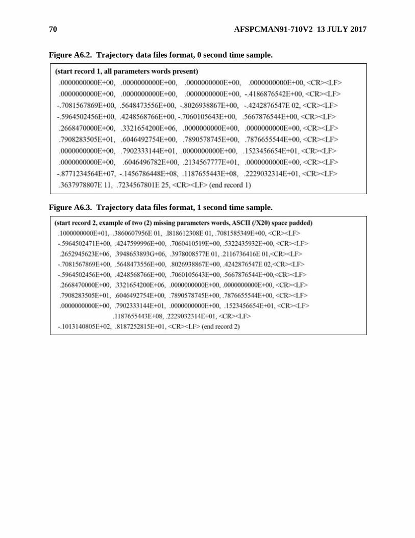
70 AFSPCMAN91-710V2 13 JULY 2017
Figure A6.2. Trajectory data files format, 0 second time sample.
Figure A6.3. Trajectory data files format, 1 second time sample.

AFSPCMAN91-710V2 13 JULY 2017 71
Figure A6.4. Trajectory data files format, 2 second time sample.
A6.3.3. Trajectory Information. Except as noted for special trajectory cases, each set of
trajectory data will include the nominal trajectory from liftoff to impact or insertion of the
payload into final orbit for each critical azimuth and for each new series of missiles. The lead
range, Flight Analysis Section, will also normally require the following 3-sigma trajectories:
maximum performance IIP, minimum performance IIP, lateral left and right IIP, steepest
launch area PP, and lateral launch area PP. These trajectories are defined in AFSPCMAN 91-
710. When dispersed trajectories are waived by Flight Analysis, dispersion increments may
be required, as applicable, for calculation of dispersed launch conditions.
A6.3.3.1. For VFA missions (normally time varying), the trajectory media should record
the trajectory data files in the order of increasing flight azimuth and day of the firing
period. For CVFA missions, trajectories are required at 3o increments across the azimuth
range desired by the range user in which a common reference azimuth is always included.
The reference azimuth should correspond to the trajectories that could be used at any
flight azimuth in the desired range with minimal error in representing the vehicle’s
expected position. Since trajectory data will be provided left and right of the reference
azimuth this may result in increments at the minimum and maximum azimuths of less
than 3o. For SVFA missions, trajectories will be defined by the Flight Analysis Section at
the respective ranges, basically defining the planar nominal (median or modal) trajectory,
and the extreme left and right yaw nominal trajectories for each fixed or discrete azimuth.
Any remaining trajectory needs at the range will be generated from discussions with the
range and Flight Analysis during mission or program introduction. Flight Analysis
Section dispersed trajectory data is normally required at least for the reference azimuth
(in the middle of the window for CVFA options and at the in-plane azimuth for SVFA
options).
A6.3.3.2. If recovery, or track, of any boost stage is required, a complete trajectory of
each such stage must be furnished. The booster trajectory, both the information file and
the trajectory data, will be recorded on a separate medium. Each applicable parameter in
the information file and each trajectory parameter indicate the decimal digits desired. The
requirement is not intended to imply significant digits or accuracy of the data.
72 AFSPCMAN91-710V2 13 JULY 2017
A6.3.3.3. Printouts from the range user should be double-spaced between items and
single-spaced within the information and data items.
A6.3.4. Sampling Rates. Normally, the time intervals at which trajectory data will be
supplied are:
A6.3.4.1. From liftoff to final thrust termination of the last thrusting stage, to thrust
termination of that stage or burn which places vehicle in orbit or to impact of any boost
segment/stage on which track or recovery is required 1-second intervals.
A6.3.4.2. During programmed changes in thrust of all other stages on which track or
recovery is required 1-second intervals.
A6.3.4.3. During free flight or coast periods not exceeding five minutes duration 1-
second intervals.
A6.3.4.4. During free flight or coast periods exceeding five minutes duration 5-second
intervals.
A6.3.4.5. From 400,000 feet altitude to impact, including reentry (300,000 feet altitude)
2 second intervals.
A6.3.4.6. During programmed changes in altitude 1-second intervals.
A6.3.4.7. At all critical times, such as burnouts, ignitions, separation events, control
mode changes, arming functions, and vehicle reorientation (change in pitch, roll or yaw),
data points will be inserted in the trajectory as to maintain a monotonic increase in time.
A6.3.4.8. During flight periods in which cameras will be used for coverage, data will be
required at least at 2-second intervals. The trajectory data need not be correlated to the
time of strobe flash or flare ejection. It is required that at least one trajectory data point be
supplied prior to the first strobe flash or flare ejection and at least one data point after the
last strobe or flare event. If the strobe or flare events occur in volleys, points are required
at the beginning and end of each volley.
A6.3.4.9. Sampling rates will be varied from this table only with approval of the Flight
Analysis Section at the lead range. The trajectory requirements will be modified by letter
from the Flight Analysis Section when not sufficient for their purposes.
A6.3.5. General Information File Items.
A6.3.5.1. Item 1. Identification of the trajectory to which data applies including program
name, PRD number and test code, missile name and number, trajectory identifier if
applicable, and Operation Number if available. (EXAMPLE Item 1. This trajectory
applies to the Atlas 50E/NOAA-D, PRD E0D31 Test Code B, Atlas 50E Launch Vehicle
and NOAA-D Spacecraft, Operation Number A0069.)
A6.3.5.2. Item 2. The date of medium issue, issue number, and whether the medium
replaces, or adds to previous identified issues. However, if any changes are made to the
data, a new medium should be prepared and transmitted to the range. (EXAMPLE Item 2.
Issued 21 June 1990. Third Revision.)

AFSPCMAN91-710V2 13 JULY 2017 73
A6.3.5.3. Item 3. The program office assigned to the program, the name of the contractor
originating the trajectory data, and enough other information to enable the range to
contact the originating range if the need arises. (EXAMPLE Item 3. Through WS lO7A
Project Office (6555/DWTD) from ACE Missile Company, PO Box 123, Los Angeles
CA 90045. John Watson, Project Engineer, Telephone Bradshaw 272-5262, Ext. 123,
TWX West Los Angeles, 6284.)
A6.3.5.4. Item 4. Designation of the pad, launcher, or launch point for the vehicle.
(EXAMPLE Item 4. This vehicle will be launched from Pad l7A.)
A6.3.5.5. Item 5. The Geodetic latitude (6D), longitude (6D), and height (3D) of the
origin of the XYZ data. This is necessary to correlate such items as trajectory and impact
point given in the trajectory files. It is also desired that the origin be identified by name
when possible. The lead range prefers that longitude be considered positive east of
Greenwich and negative from 0 degrees to 180 degrees west of Greenwich. However, for
those range users not following this convention, the lead range will provide for changes
in sign within its computer programs. Longitude values provided should specify East or
West. Southerly latitudes will be considered as negative. (EXAMPLE Item 5. The origin
of the XYZ data is the intersection of the launch stand pin plane and the missile center
line and is located at 28.327621 degrees north Geodetic latitude and -80.326241 degrees
west longitude and 42.826 feet above mean sea level.)
A6.3.5.6. Item 6. Physical relationship (2D) of the tracking point on the missile to the
trajectory data origin.
A6.3.5.7. Item 7. Azimuth (3D) of the X-axis of the XYZ system measured from true
north. This azimuth would normally be the final flight azimuth or rolled azimuth. For
VFA launches, the azimuths of the X-axis are specified in the information items as set
forth under this option. When this condition is used, the words "Variable Window
Launch" should be mentioned. (EXAMPLE Item 7. The azimuth of the X axis is 105.001
degrees from true north.)
A6.3.5.8. Item 8. Name of earth model used in calculations. (EXAMPLE Item 8. The
earth model used in DoD/WGS 1984 (or currently applicable DoD earth model.)
A6.3.5.9. Item 9. Data units of parameters used. English or SI units are acceptable.
A6.3.5.10. Item 10. All critical times (3D) in seconds. For VFA launches, critical times
are requested in specific options. (EXAMPLE Item 10.)
Figure A6.5. EXAMPLE Item 10.
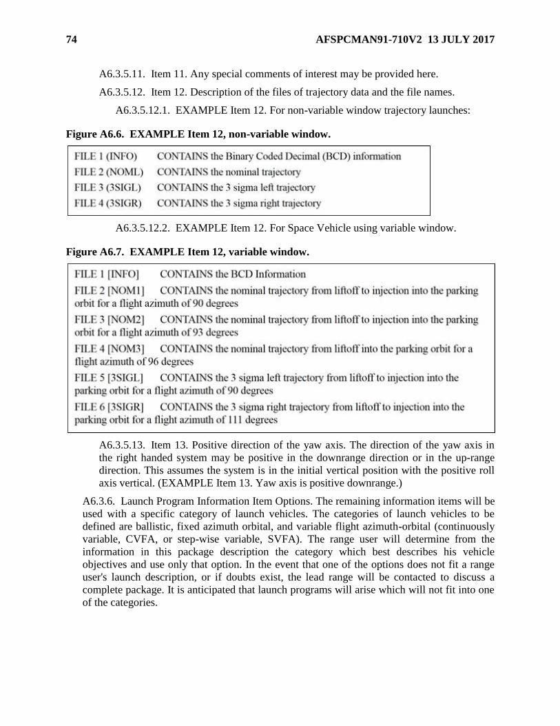
74 AFSPCMAN91-710V2 13 JULY 2017
A6.3.5.11. Item 11. Any special comments of interest may be provided here.
A6.3.5.12. Item 12. Description of the files of trajectory data and the file names.
A6.3.5.12.1. EXAMPLE Item 12. For non-variable window trajectory launches:
Figure A6.6. EXAMPLE Item 12, non-variable window.
A6.3.5.12.2. EXAMPLE Item 12. For Space Vehicle using variable window.
Figure A6.7. EXAMPLE Item 12, variable window.
A6.3.5.13. Item 13. Positive direction of the yaw axis. The direction of the yaw axis in
the right handed system may be positive in the downrange direction or in the up-range
direction. This assumes the system is in the initial vertical position with the positive roll
axis vertical. (EXAMPLE Item 13. Yaw axis is positive downrange.)
A6.3.6. Launch Program Information Item Options. The remaining information items will be
used with a specific category of launch vehicles. The categories of launch vehicles to be
defined are ballistic, fixed azimuth orbital, and variable flight azimuth-orbital (continuously
variable, CVFA, or step-wise variable, SVFA). The range user will determine from the
information in this package description the category which best describes his vehicle
objectives and use only that option. In the event that one of the options does not fit a range
user's launch description, or if doubts exist, the lead range will be contacted to discuss a
complete package. It is anticipated that launch programs will arise which will not fit into one
of the categories.

AFSPCMAN91-710V2 13 JULY 2017 75
A6.3.6.1. Option 1A. Ballistic Type Launch with single R/V (reentry vehicle). The
additional information items for single R/V ballistic type programs are:
A6.3.6.1.1. Item 14. Total time (3D) of flight in seconds. (EXAMPLE Item 14. The
total time of flight from liftoff to impact is 1456.080 seconds.)
A6.3.6.1.2. Item 15. Range (4D) to target. (EXAMPLE Item 15. The range from
launch pad to target is 13,200.6231 Nautical Miles.)
A6.3.6.1.3. Item 16. Geodetic latitude (6D) and longitude (6D) of target. See
information Item 5 for the definition of longitude. (EXAMPLE Item 16. The target is
2.621486 degrees north geodetic latitude and -1.421634 degrees west longitude.)
A6.3.6.1.4. Item 17. Weight (1D) of reentry vehicle for drag calculations.
(EXAMPLE Item 17. The reentry vehicle weighs 1062.3 pounds.)
A6.3.6.1.5. Item 18. Reference cross sectional area (3D) for drag calculations.
(EXAMPLE Item 18. Cross sectional area of the reentry vehicle is 93.321 square
feet.)
A6.3.6.1.6. Item 19. Table of coefficients of drag (2D) versus Mach number (2D) for
defining drag curve of re-entry vehicle, when there is to be a recovery. (EXAMPLE
Item 19.)
Figure A6.8. EXAMPLE Item 19.
A6.3.6.1.6.1. This table should contain a minimum of 30 points. Sufficient points
should be chosen such that a series of straight lines will reproduce the curve.
Coefficients of drag should be included for a zero Mach number and for at least
two Mach numbers greater than the expected performance maximum.
A6.3.6.1.6.2. For booster recovery data or track, the coefficient of drag table for
the boost body should reflect what the range user considers will be the most likely
flight configuration. Note: Where the cross sectional area, weight, and
coefficients of drag are Restricted Data, place the statement "See Item 19" in both
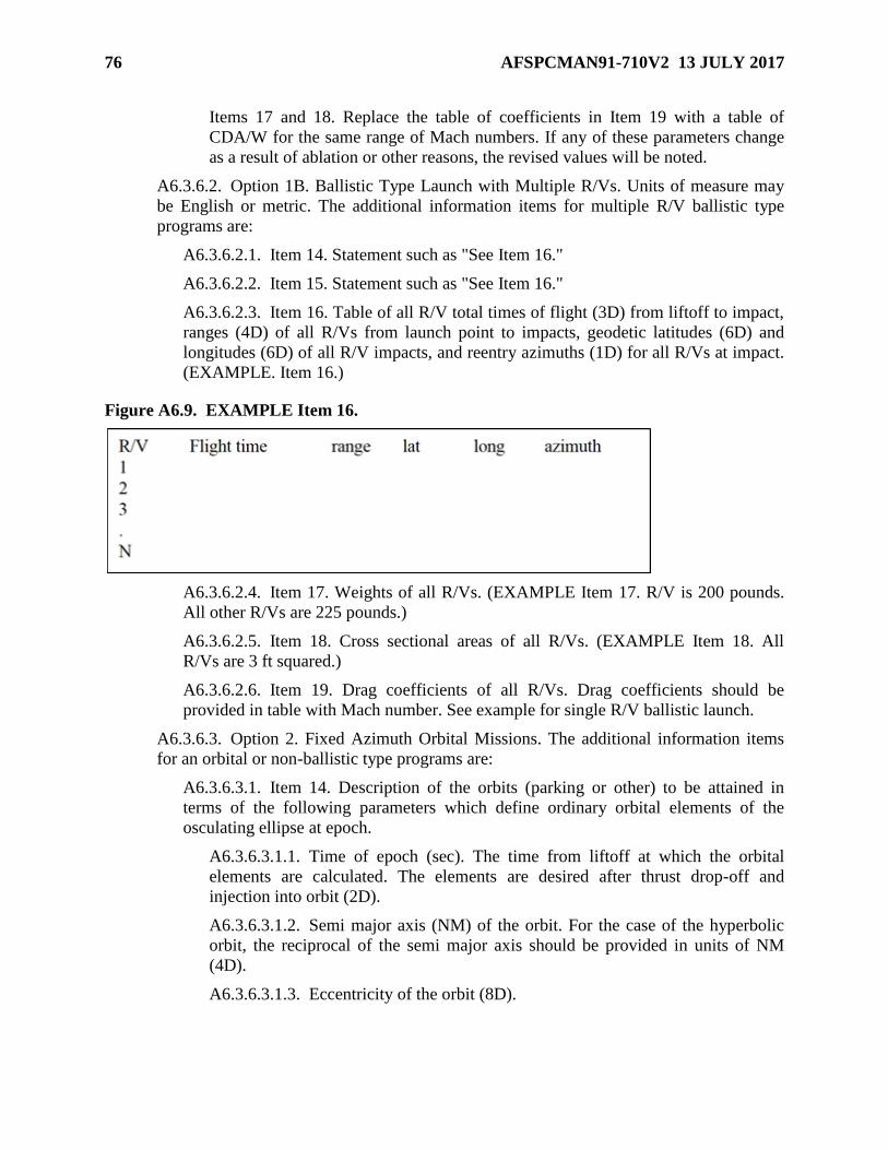
76 AFSPCMAN91-710V2 13 JULY 2017
Items 17 and 18. Replace the table of coefficients in Item 19 with a table of
CDA/W for the same range of Mach numbers. If any of these parameters change
as a result of ablation or other reasons, the revised values will be noted.
A6.3.6.2. Option 1B. Ballistic Type Launch with Multiple R/Vs. Units of measure may
be English or metric. The additional information items for multiple R/V ballistic type
programs are:
A6.3.6.2.1. Item 14. Statement such as "See Item 16."
A6.3.6.2.2. Item 15. Statement such as "See Item 16."
A6.3.6.2.3. Item 16. Table of all R/V total times of flight (3D) from liftoff to impact,
ranges (4D) of all R/Vs from launch point to impacts, geodetic latitudes (6D) and
longitudes (6D) of all R/V impacts, and reentry azimuths (1D) for all R/Vs at impact.
(EXAMPLE. Item 16.)
Figure A6.9. EXAMPLE Item 16.
A6.3.6.2.4. Item 17. Weights of all R/Vs. (EXAMPLE Item 17. R/V is 200 pounds.
All other R/Vs are 225 pounds.)
A6.3.6.2.5. Item 18. Cross sectional areas of all R/Vs. (EXAMPLE Item 18. All
R/Vs are 3 ft squared.)
A6.3.6.2.6. Item 19. Drag coefficients of all R/Vs. Drag coefficients should be
provided in table with Mach number. See example for single R/V ballistic launch.
A6.3.6.3. Option 2. Fixed Azimuth Orbital Missions. The additional information items
for an orbital or non-ballistic type programs are:
A6.3.6.3.1. Item 14. Description of the orbits (parking or other) to be attained in
terms of the following parameters which define ordinary orbital elements of the
osculating ellipse at epoch.
A6.3.6.3.1.1. Time of epoch (sec). The time from liftoff at which the orbital
elements are calculated. The elements are desired after thrust drop-off and
injection into orbit (2D).
A6.3.6.3.1.2. Semi major axis (NM) of the orbit. For the case of the hyperbolic
orbit, the reciprocal of the semi major axis should be provided in units of NM
(4D).
A6.3.6.3.1.3. Eccentricity of the orbit (8D).

AFSPCMAN91-710V2 13 JULY 2017 77
A6.3.6.3.1.4. Inclination (deg). The angle between the plane of the orbit and the
plane of the equator measured from the plane of the equator at the ascending
node. If the direction of motion of the satellite is the same as the earth's rotation, it
is called direct and the inclination will be less than 90 degrees. However, if the
motion is opposite to the rotation of the earth, the orbit is called retrograde and the
inclination will be greater than 90 degrees. The limits of the inclination (i) will be
0o < i < 180o (4D).
A6.3.6.3.1.5. Longitude of the ascending node (deg). The angle measured
eastward from the Greenwich meridian to the intersection of the equatorial plane
and the orbital plane fixed at the time of epoch conditions when the path crosses
the equatorial plane from south to north. The limits for the angle (Ω) will be 0o <
Ω < 360o (4D).
A6.3.6.3.1.6. Argument of Perigee (deg). The angle between the ascending node
and the perigee is measured at the elliptical focus (center of the earth) in the plane
of the orbit and in the direction of the satellite's motion. For a circular orbit, the
argument of the perigee will be computed at the epoch point. The limits for the
argument of perigee (ω) will be 0o < ω < 360o (4D).
A6.3.6.3.1.7. Sum of True Anomaly and Argument of Perigee (deg). The true
anomaly is the angle from the perigee point to the satellite at epoch measured at
the elliptical focus in the direction of satellite motion. For circular orbits, perigee
is taken at the time of epoch and thus the true anomaly would be zero. The limits
for (υ+ω) will be 00 < ω < 360o (4D).
A6.3.6.3.1.8. Period (min). The time between two successive perigee passages in
Keplerian motion, defined in terms of semi major axis of the osculating ellipse
(4D).
A6.3.6.3.1.9. Mean Anomaly (deg). The angle at the focus described by the
radius vector moving at a mean angular rate n (n=2π /period). Measured from
perigee to the satellite at the time of epoch. The limits for the mean anomaly (M)
will be 00 < M < 360o (4D).
A6.3.6.3.1.10. Time of Apogee (min). Time from liftoff to apogee passage. For
the hyperbolic orbit this item should be the time of perigee and would be the time
from liftoff to perigee passage (4D).
A6.3.6.3.1.11. Height of Apogee (NM). Height above ellipsoidal earth along the
local geocentric vertical. For the hyperbolic orbit this item is not applicable and
the term "hyperbolic orbit" should be inserted in this location (4D).
A6.3.6.3.1.12. Height of Perigee (NM). Height above ellipsoidal earth along the
local geocentric vertical (4D). (The parabolic orbit is not discussed but rather is
considered as a special case of the hyperbolic orbit.) (EXAMPLE Item 14.)
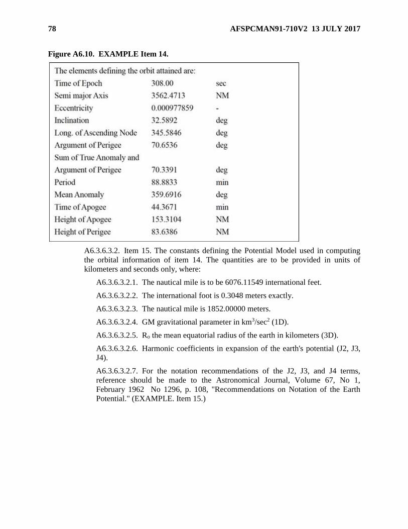
78 AFSPCMAN91-710V2 13 JULY 2017
Figure A6.10. EXAMPLE Item 14.
A6.3.6.3.2. Item 15. The constants defining the Potential Model used in computing
the orbital information of item 14. The quantities are to be provided in units of
kilometers and seconds only, where:
A6.3.6.3.2.1. The nautical mile is to be 6076.11549 international feet.
A6.3.6.3.2.2. The international foot is 0.3048 meters exactly.
A6.3.6.3.2.3. The nautical mile is 1852.00000 meters.
A6.3.6.3.2.4. GM gravitational parameter in km3/sec2 (1D).
A6.3.6.3.2.5. Ro the mean equatorial radius of the earth in kilometers (3D).
A6.3.6.3.2.6. Harmonic coefficients in expansion of the earth's potential (J2, J3,
J4).
A6.3.6.3.2.7. For the notation recommendations of the J2, J3, and J4 terms,
reference should be made to the Astronomical Journal, Volume 67, No 1,
February 1962 No 1296, p. 108, "Recommendations on Notation of the Earth
Potential." (EXAMPLE. Item 15.)

AFSPCMAN91-710V2 13 JULY 2017 79
Figure A6.11. EXAMPLE Item 15.
A6.3.6.3.3. Item 16. Geodetic latitude (6D) and longitude (6D) of target, when there
is to be a recovery. (EXAMPLE. Item 16. The target is 2.621486 degrees north
latitude and -1.421634 degrees west longitude.)
A6.3.6.3.4. Item 17. Weight (1D) of reentry vehicle, when there is to be a recovery.
(EXAMPLE Item 17. The reentry vehicle weighs 1062.3 pounds.)
A6.3.6.3.5. Item 18. Referenced cross sectional area (3D), when there is to be a
recovery. (EXAMPLE Item 18. Cross sectional area of the reentry vehicle data in
item 16 is 93.321 square feet.)
A6.3.6.3.6. Item 19. Table of coefficients of drag (2D) versus Mach number (2D) for
defining drag curve of reentry vehicle, when there is to be a recovery. (EXAMPLE
Item 19.)
Figure A6.12. EXAMPLE Item 19.
A6.3.6.3.6.1. This table will contain a minimum of 30 points, sufficiently chosen
such that a series of straight lines would reproduce the curve. Coefficients of drag
will be included for zero Mach number and for at least two Mach numbers greater
than the expected performance maximum.
A6.3.6.3.6.2. For booster recovery data, the coefficient of drag table for the boost
body should reflect what the range user considers will be the most likely flight
configuration. (Where the cross sectional area, weight, and coefficients of drag
are Restricted Data, place the stated "See Item 19" in both items 17 and 18.
Replace the Table of Coefficients in item 19 with a Table of CDA/W for the same
range of Mach numbers.)
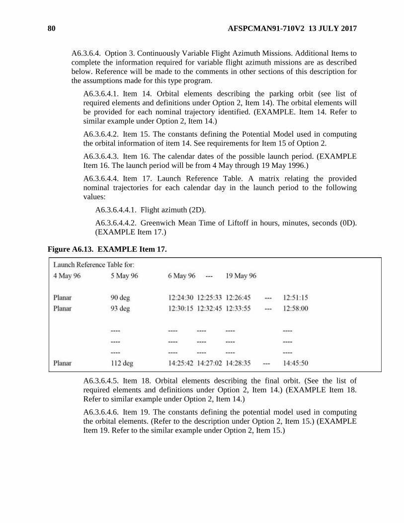
80 AFSPCMAN91-710V2 13 JULY 2017
A6.3.6.4. Option 3. Continuously Variable Flight Azimuth Missions. Additional Items to
complete the information required for variable flight azimuth missions are as described
below. Reference will be made to the comments in other sections of this description for
the assumptions made for this type program.
A6.3.6.4.1. Item 14. Orbital elements describing the parking orbit (see list of
required elements and definitions under Option 2, Item 14). The orbital elements will
be provided for each nominal trajectory identified. (EXAMPLE. Item 14. Refer to
similar example under Option 2, Item 14.)
A6.3.6.4.2. Item 15. The constants defining the Potential Model used in computing
the orbital information of item 14. See requirements for Item 15 of Option 2.
A6.3.6.4.3. Item 16. The calendar dates of the possible launch period. (EXAMPLE
Item 16. The launch period will be from 4 May through 19 May 1996.)
A6.3.6.4.4. Item 17. Launch Reference Table. A matrix relating the provided
nominal trajectories for each calendar day in the launch period to the following
values:
A6.3.6.4.4.1. Flight azimuth (2D).
A6.3.6.4.4.2. Greenwich Mean Time of Liftoff in hours, minutes, seconds (0D).
(EXAMPLE Item 17.)
Figure A6.13. EXAMPLE Item 17.
A6.3.6.4.5. Item 18. Orbital elements describing the final orbit. (See the list of
required elements and definitions under Option 2, Item 14.) (EXAMPLE Item 18.
Refer to similar example under Option 2, Item 14.)
A6.3.6.4.6. Item 19. The constants defining the potential model used in computing
the orbital elements. (Refer to the description under Option 2, Item 15.) (EXAMPLE
Item 19. Refer to the similar example under Option 2, Item 15.)

AFSPCMAN91-710V2 13 JULY 2017 81
A6.3.6.5. Option 4. Stepwise Variable Flight Azimuth Missions. The present trajectory
package is to include complete trajectories for each reference azimuth for each day of any
launch opportunity under consideration. The package also specifies flight azimuth
increments, sampling rates, listing of orbital parameters and critical event times, and
other associated items. Dispersion trajectories as such (i.e., 3 sigma Maximum IIP, 3
sigma Minimum IIP, 3 sigma Left and Right Lateral IIP) are also required. Additional
Items to complete the information required for stepwise variable flight azimuth missions
are as described below. Reference will be made to the comments in other sections of this
description for the assumptions made for this type program.
A6.3.6.5.1. Item 14. Orbital elements describing the parking orbit (see list of
required elements and definitions under Option 2, Item 14). The orbital elements will
be provided for each nominal trajectory identified. (EXAMPLE Item 14. Refer to
similar example under Option 2, Item 14.)
A6.3.6.5.2. Item 15. The constants defining the Potential Model used in computing
the orbital information of item 14. See requirements for Item 15 of Option 2.
A6.3.6.5.3. Item 16. The calendar dates of the possible launch period. (EXAMPLE
Item 16. The launch period will be from 4 May through 19 May 1996.)
A6.3.6.5.4. Item 17. Launch Reference Table. A matrix relating the provided
nominal trajectories for each calendar day in the launch period to the following
values:
A6.3.6.5.4.1. Flight azimuth (2D).
A6.3.6.5.4.2. Greenwich Mean Time of Liftoff in hours, minutes, seconds (0D).
Figure A6.14. EXAMPLE Item 17.
A6.3.6.5.5. Item 18. Orbital elements describing the final orbit. (See the list of
required elements and definitions under Option 2, Item 14.) (EXAMPLE Item 18.
Refer to similar example under Option 2, Item 14.)
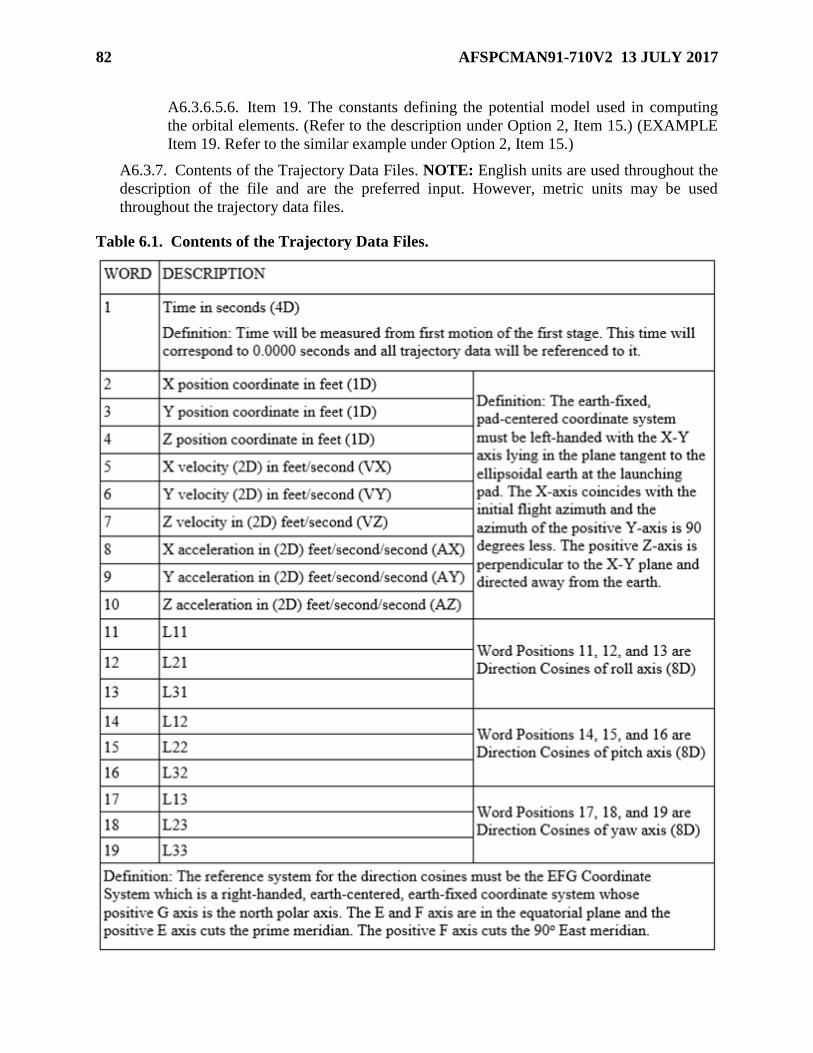
82 AFSPCMAN91-710V2 13 JULY 2017
A6.3.6.5.6. Item 19. The constants defining the potential model used in computing
the orbital elements. (Refer to the description under Option 2, Item 15.) (EXAMPLE
Item 19. Refer to the similar example under Option 2, Item 15.)
A6.3.7. Contents of the Trajectory Data Files. NOTE: English units are used throughout the
description of the file and are the preferred input. However, metric units may be used
throughout the trajectory data files.
Table 6.1. Contents of the Trajectory Data Files.
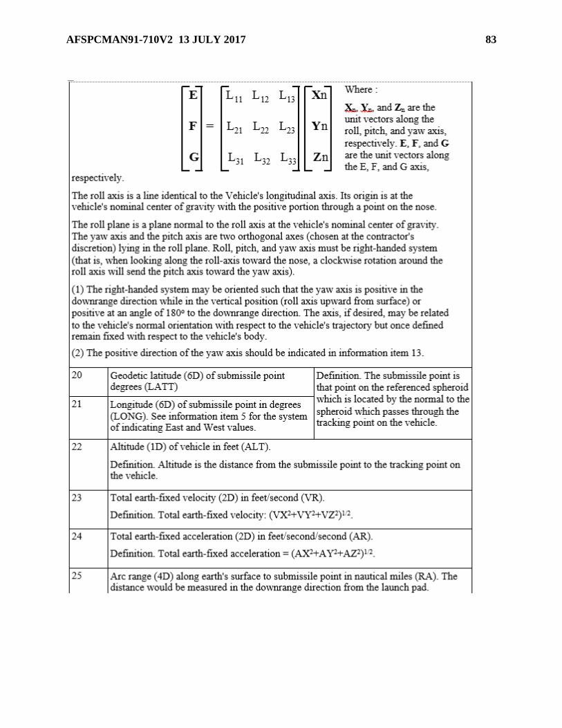
AFSPCMAN91-710V2 13 JULY 2017 83
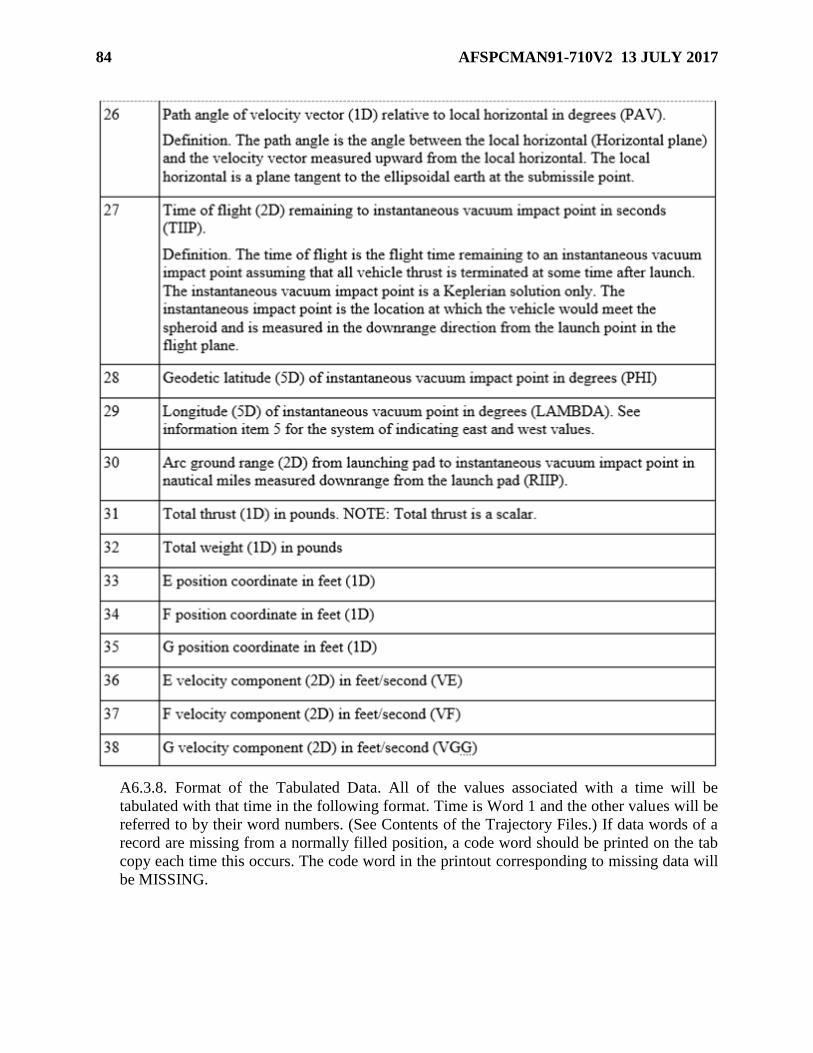
84 AFSPCMAN91-710V2 13 JULY 2017
A6.3.8. Format of the Tabulated Data. All of the values associated with a time will be
tabulated with that time in the following format. Time is Word 1 and the other values will be
referred to by their word numbers. (See Contents of the Trajectory Files.) If data words of a
record are missing from a normally filled position, a code word should be printed on the tab
copy each time this occurs. The code word in the printout corresponding to missing data will
be MISSING.
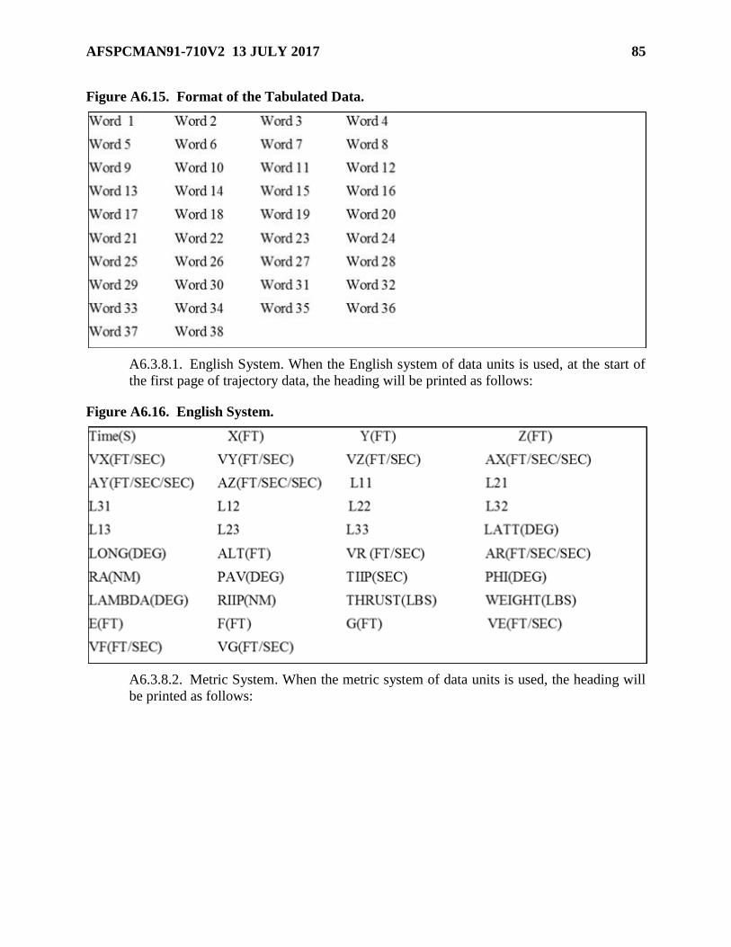
AFSPCMAN91-710V2 13 JULY 2017 85
Figure A6.15. Format of the Tabulated Data.
A6.3.8.1. English System. When the English system of data units is used, at the start of
the first page of trajectory data, the heading will be printed as follows:
Figure A6.16. English System.
A6.3.8.2. Metric System. When the metric system of data units is used, the heading will
be printed as follows:
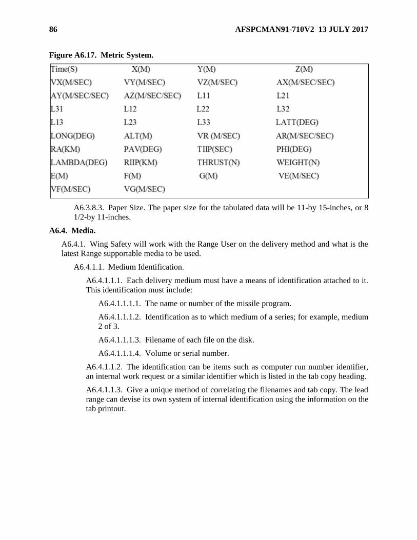
86 AFSPCMAN91-710V2 13 JULY 2017
Figure A6.17. Metric System.
A6.3.8.3. Paper Size. The paper size for the tabulated data will be 11-by 15-inches, or 8
1/2-by 11-inches.
A6.4. Media.
A6.4.1. Wing Safety will work with the Range User on the delivery method and what is the
latest Range supportable media to be used.
A6.4.1.1. Medium Identification.
A6.4.1.1.1. Each delivery medium must have a means of identification attached to it.
This identification must include:
A6.4.1.1.1.1. The name or number of the missile program.
A6.4.1.1.1.2. Identification as to which medium of a series; for example, medium
2 of 3.
A6.4.1.1.1.3. Filename of each file on the disk.
A6.4.1.1.1.4. Volume or serial number.
A6.4.1.1.2. The identification can be items such as computer run number identifier,
an internal work request or a similar identifier which is listed in the tab copy heading.
A6.4.1.1.3. Give a unique method of correlating the filenames and tab copy. The lead
range can devise its own system of internal identification using the information on the
tab printout.
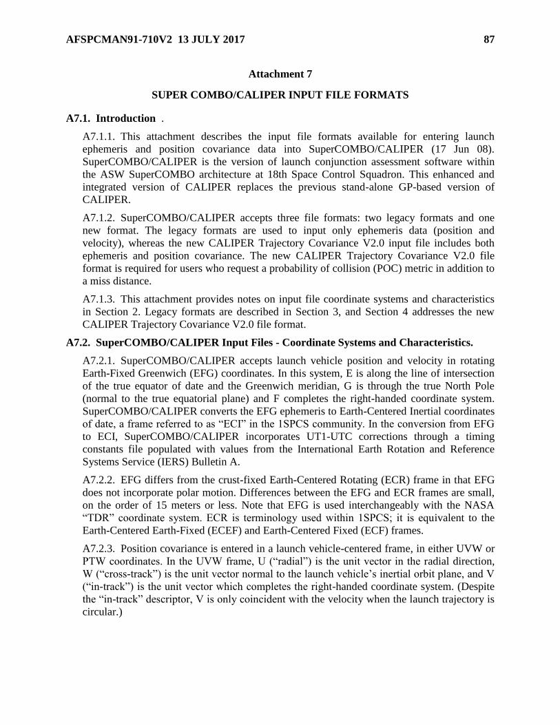
AFSPCMAN91-710V2 13 JULY 2017 87
Attachment 7
SUPER COMBO/CALIPER INPUT FILE FORMATS
A7.1. Introduction .
A7.1.1. This attachment describes the input file formats available for entering launch
ephemeris and position covariance data into SuperCOMBO/CALIPER (17 Jun 08).
SuperCOMBO/CALIPER is the version of launch conjunction assessment software within
the ASW SuperCOMBO architecture at 18th Space Control Squadron. This enhanced and
integrated version of CALIPER replaces the previous stand-alone GP-based version of
CALIPER.
A7.1.2. SuperCOMBO/CALIPER accepts three file formats: two legacy formats and one
new format. The legacy formats are used to input only ephemeris data (position and
velocity), whereas the new CALIPER Trajectory Covariance V2.0 input file includes both
ephemeris and position covariance. The new CALIPER Trajectory Covariance V2.0 file
format is required for users who request a probability of collision (POC) metric in addition to
a miss distance.
A7.1.3. This attachment provides notes on input file coordinate systems and characteristics
in Section 2. Legacy formats are described in Section 3, and Section 4 addresses the new
CALIPER Trajectory Covariance V2.0 file format.
A7.2. SuperCOMBO/CALIPER Input Files - Coordinate Systems and Characteristics.
A7.2.1. SuperCOMBO/CALIPER accepts launch vehicle position and velocity in rotating
Earth-Fixed Greenwich (EFG) coordinates. In this system, E is along the line of intersection
of the true equator of date and the Greenwich meridian, G is through the true North Pole
(normal to the true equatorial plane) and F completes the right-handed coordinate system.
SuperCOMBO/CALIPER converts the EFG ephemeris to Earth-Centered Inertial coordinates
of date, a frame referred to as “ECI” in the 1SPCS community. In the conversion from EFG
to ECI, SuperCOMBO/CALIPER incorporates UT1-UTC corrections through a timing
constants file populated with values from the International Earth Rotation and Reference
Systems Service (IERS) Bulletin A.
A7.2.2. EFG differs from the crust-fixed Earth-Centered Rotating (ECR) frame in that EFG
does not incorporate polar motion. Differences between the EFG and ECR frames are small,
on the order of 15 meters or less. Note that EFG is used interchangeably with the NASA
“TDR” coordinate system. ECR is terminology used within 1SPCS; it is equivalent to the
Earth-Centered Earth-Fixed (ECEF) and Earth-Centered Fixed (ECF) frames.
A7.2.3. Position covariance is entered in a launch vehicle-centered frame, in either UVW or
PTW coordinates. In the UVW frame, U (“radial”) is the unit vector in the radial direction,
W (“cross-track”) is the unit vector normal to the launch vehicle’s inertial orbit plane, and V
(“in-track”) is the unit vector which completes the right-handed coordinate system. (Despite
the “in-track” descriptor, V is only coincident with the velocity when the launch trajectory is
circular.)

88 AFSPCMAN91-710V2 13 JULY 2017
A7.2.4. In the PTW covariance frame, T is the unit vector along the launch vehicle’s
velocity vector, W is again the unit vector normal to the launch vehicle’s inertial orbit plane,
and P is the unit vector that completes the right-handed coordinate system. PTW is the most
easily visualized covariance frame for elliptical launch vehicle trajectories because the T
direction is aligned with the launch vehicle’s velocity.
A7.2.5. The SuperCOMBO/CALIPER launch trajectory input file should have
ephemeris/covariance points provided at sufficiently frequent time points that interpolation
may be used with negligible error. For boosting launch trajectories, an ephemeris/covariance
point spacing of 10 seconds is recommended – although less than 10 second spacing could be
needed if the trajectory contains large maneuvers. For non-boosting, non-maneuvering
phases of a launch trajectory profile, larger ephemeris/covariance point spacing can be used.
Note that SuperCOMBO/CALIPER can accept launch trajectory files with variable
ephemeris/covariance point spacing.
A7.2.6. Because launch vehicle velocity is used for both interpolation and for identifying
potential conjunctions, SuperCOMBO/CALIPER requires that the launch vehicle velocity be
realistic such that the EFG velocity represents the derivative of the EFG position. Also, the
position and velocity ephemeris points should be relatively smooth and continuous (e.g., real
world delta-Vs for maneuvers are acceptable but large deviations particularly those that are
discontinuous step functions are not).
A7.2.7. For meaningful POC calculations, the launching agency must provide realistic
launch trajectory covariance. For responsible decision making based on POC, the launching
authority must be knowledgeable on the POC metric and its use/limitations.
A7.3. Legacy File Formats for Ephemeris Data Only.
A7.3.1. There are two file formats for entering only ephemeris (position and velocity). They
are legacy formats from the previous stand-alone CALIPER. One is the standard CALIPER
trajectory file format. The other is a more concise, space-delimited, free-format that had to be
processed before being input into the previous version of CALIPER, but can now be input
directly into SuperCOMBO/CALIPER. Both formats are described in the following
paragraphs.
A7.3.1.1. CALIPER Trajectory File
A7.3.1.1.1. In the CALIPER Trajectory file, one or more launch times/trajectories
can be represented in a single file. In the previous version of CALIPER, all launch
times in a launch window had to be represented in a single file.
A7.3.1.1.2. Now, you can input a single trajectory and either run it as is in
SuperCOMBO/CALIPER or you can override the launch time and input launch
window start/stop/time steps. Since most launch profiles maintain the same earth-
fixed trajectory throughout the launch window, this approach is desirable as it
requires less I/O processing time. However, if the earth-fixed trajectories do differ
with each new launch time (e.g., launch azimuth varies for interplanetary launch
opportunities), then all launch times/trajectories will have to be submitted within a
single file.
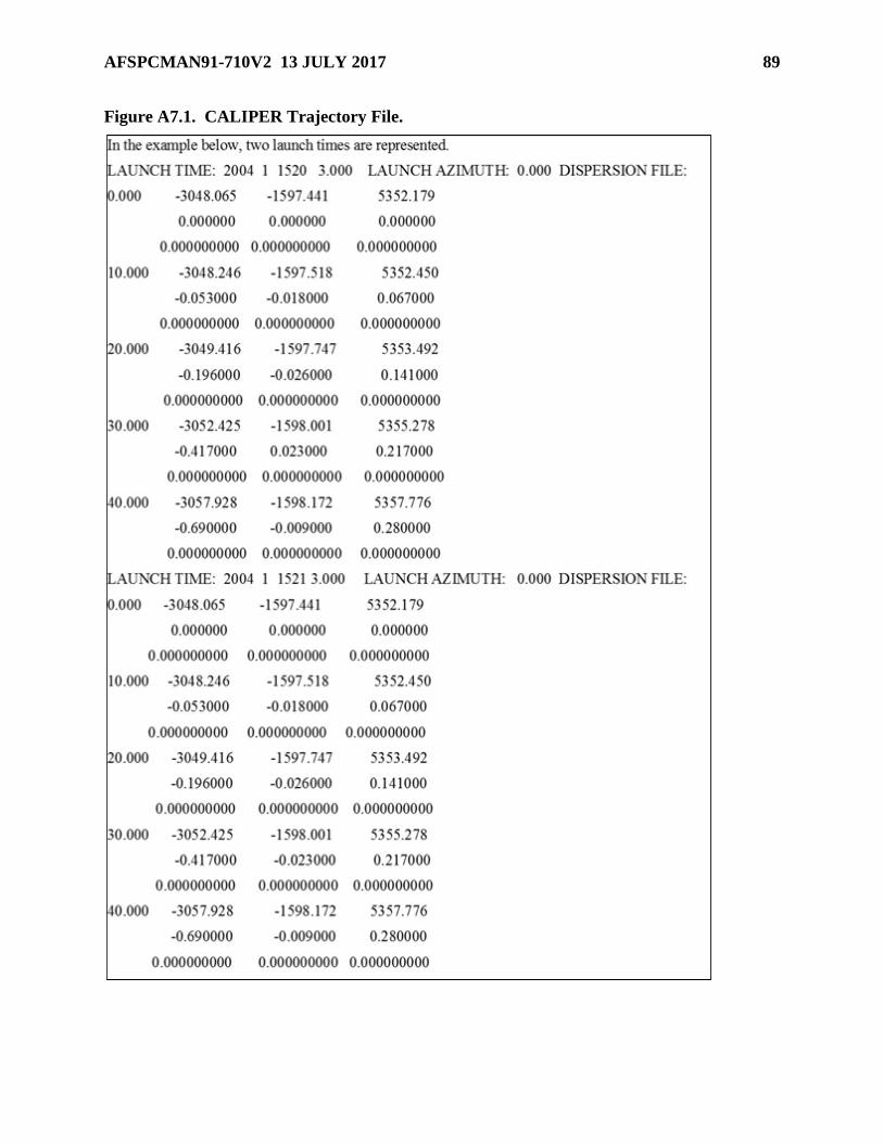
AFSPCMAN91-710V2 13 JULY 2017 89
Figure A7.1. CALIPER Trajectory File.

90 AFSPCMAN91-710V2 13 JULY 2017
A7.3.1.1.3. A line with the launch time separates each EFG trajectory. Launch
Azimuth and the Dispersion File are not used. The first line of each ephemeris point
record contains time since launch in seconds followed by the XYZ components of
EFG position in km. The second line contains the XYZ components of EFG velocity
in km/s. The third line is a placeholder for acceleration of the asset, but acceleration is
not currently used.
A7.3.1.1.4. Any single CALIPER trajectory for a given launch time must contain a
minimum of 5 points and a maximum of 25000 points. The maximum number of
seconds since epoch is 999999.999 seconds, equivalent to 11.574 days.
A7.3.1.2. Free-Format Ephemeris File
A7.3.1.2.1. The second format is a concise, space-delimited, free-format. In the
previous version of CALIPER, it had to be processed before being input into the
program. Now it can be directly input into SuperCOMBO/CALIPER. An example is
provided below.
Figure A7.2. Free-Format Ephemeris File.
A7.3.1.2.2. This EFG file of positions and velocities is independent of launch time.
Launch window start/stop/spans are entered within the SuperCOMBO/CALIPER
program. Numbers are in standard double precision format (not scientific/exponential
format).
A7.3.1.2.3. The first column is time since launch in seconds. The next three columns
are the XYZ components of EFG position in km. The last three columns are the XYZ
components of EFG velocity in km/s.

AFSPCMAN91-710V2 13 JULY 2017 91
A7.4. CALIPER Trajectory Covariance V 2 File Format.
A7.4.1. The elements of the CALIPER Trajectory Covariance V2.0 format are shown below.
Figure A7.3. CALIPER Trajectory Covariance V 2 Format.
A7.4.2. A sample CALIPER Trajectory Covariance V2.0 file is shown next.
Figure A7.4. Sample CALIPER Trajectory Covariance V 2 file.
A7.4.3. A CALIPER Trajectory Covariance V2.0 file begins with 2 header lines.
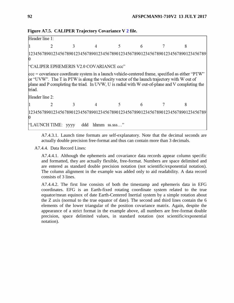
92 AFSPCMAN91-710V2 13 JULY 2017
Figure A7.5. CALIPER Trajectory Covariance V 2 file.
A7.4.3.1. Launch time formats are self-explanatory. Note that the decimal seconds are
actually double precision free-format and thus can contain more than 3 decimals.
A7.4.4. Data Record Lines:
A7.4.4.1. Although the ephemeris and covariance data records appear column specific
and formatted, they are actually flexible, free-format. Numbers are space delimited and
are entered as standard double precision notation (not scientific/exponential notation).
The column alignment in the example was added only to aid readability. A data record
consists of 3 lines.
A7.4.4.2. The first line consists of both the timestamp and ephemeris data in EFG
coordinates. EFG is an Earth-fixed rotating coordinate system related to the true
equator/mean equinox of date Earth-Centered Inertial system by a simple rotation about
the Z axis (normal to the true equator of date). The second and third lines contain the 6
elements of the lower triangular of the position covariance matrix. Again, despite the
appearance of a strict format in the example above, all numbers are free-format double
precision, space delimited values, in standard notation (not scientific/exponential
notation).
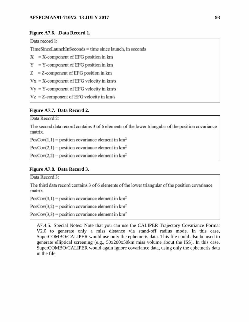
AFSPCMAN91-710V2 13 JULY 2017 93
Figure A7.6. .Data Record 1.
Figure A7.7. Data Record 2.
Figure A7.8. Data Record 3.
A7.4.5. Special Notes: Note that you can use the CALIPER Trajectory Covariance Format
V2.0 to generate only a miss distance via stand-off radius mode. In this case,
SuperCOMBO/CALIPER would use only the ephemeris data. This file could also be used to
generate elliptical screening (e.g., 50x200x50km miss volume about the ISS). In this case,
SuperCOMBO/CALIPER would again ignore covariance data, using only the ephemeris data
in the file.
94 AFSPCMAN91-710V2 13 JULY 2017
Attachment 8
RRAT COVARIANCE INPUT FILE FORMATS
A8.1. Introduction. The debris risk program used by the Air Force and FAA accept three file
formats that define the uncertainty in position and velocity of the nominal trajectory due to
guidance and performance uncertainties. The Metric Covariance (MCOV), and Guidance and
Performance State Vector (GPSV) formats are the preferred formats. The MBOD format uses a
vehicle velocity based coordinate system and the GPSV format is used when providing Monte
Carlo trajectory results. The three formats are detailed below:
A8.1.1. The Metric Covariance (MCOV) data file format allows the user to input directly the
full 6x6 covariance matrix in earth centered, rotating (ECR, consisting of EFG axes fixed in
the rotating earth) coordinates. The MCOV representation of uncertainty is the same as is
used internally in CRTF; all other inputs are transformed to this coordinate system.
Therefore, this input method provides the most control for the user, but the file is more
difficult to create and to understand than other formats. Note that in the current version of the
computation, the off-diagonal 3x3 position and velocity covariance matrices (top right 3x3
and bottom left 3x3) are not used due to problems with numerical decomposition of near-
singular matrices—instead, they are replaced with zeroes. Neglecting these terms typically
has little effect on the resulting dispersions.
A8.1.2. A second input format, MBOD, is similar to the MCOV format but it is in a different
coordinate system. The MBOD format looks the same as MCOV as it includes the full
covariance matrix. The coordinate system is relative to the vehicle velocity vector. The body-
axis system is defined such that (1,1) is the variance along the axial vector of the vehicle
(assumed to be in the direction of the velocity vector), (2,2) is the variance in the yaw
direction, and (3,3) is the variance in the pitch direction. These correspond to the standard
xyz coordinates of the body-axis system. Like the MCOV format, the off-diagonal 3x3
covariance matrices are not used and are replaced by zeroes.
A8.1.3. Guidance and Performance State Vector (GPSV) data file format allows for the
input of Monte Carlo simulations of the nominal trajectory. These sources of metric
uncertainty may represent variations of the initial conditions or variations of the forces on the
vehicle as it moves along its flight path. Several hundred simulation trajectories are usually
required to obtain sufficient statistics to accurately sample the uncertainty. When a GPSV file
is used in an analysis, the position-velocity covariance is computed from all the state vectors
at each state time, and that uncertainty is used. CRTF also writes the covariance to an MCOV
format file called “Metric_Cov.Dat”. Use of the MCOV format is faster than the GPSV
format, and therefore it is often more efficient to generate the “Metric_Cov.Dat” file once (by
running CRTF), and then change the metric file specification to point to this generated file.
This is particularly important when CRTF is run remotely, because CRTF is executed many
times with the same metric file.
A8.2. RRAT File Format Requirements.
A8.2.1. MCOV File Format. The MCOV file is ASCII, and is in a free field format so the
data must obey ADA standards.
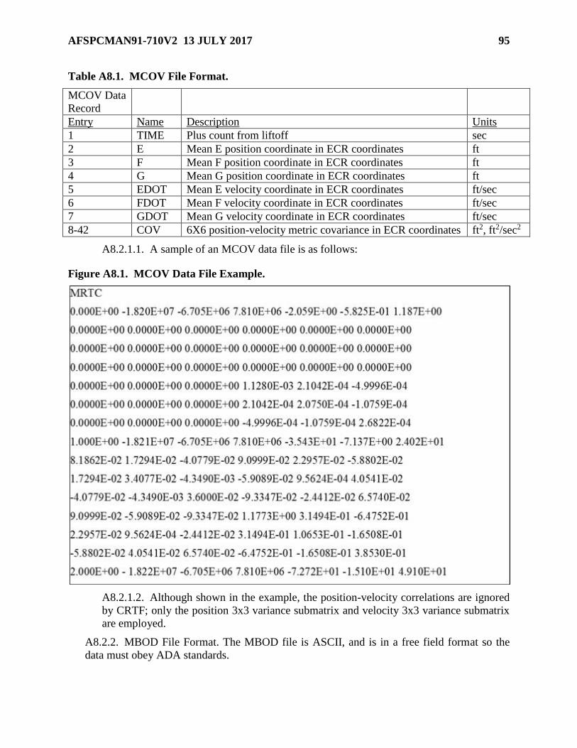
AFSPCMAN91-710V2 13 JULY 2017 95
Table A8.1. MCOV File Format.
MCOV Data
Record
Entry Name Description Units
1 TIME Plus count from liftoff sec
2 E Mean E position coordinate in ECR coordinates ft
3 F Mean F position coordinate in ECR coordinates ft
4 G Mean G position coordinate in ECR coordinates ft
5 EDOT Mean E velocity coordinate in ECR coordinates ft/sec
6 FDOT Mean F velocity coordinate in ECR coordinates ft/sec
7 GDOT Mean G velocity coordinate in ECR coordinates ft/sec
8-42 COV 6X6 position-velocity metric covariance in ECR coordinates ft2, ft2/sec2
A8.2.1.1. A sample of an MCOV data file is as follows:
Figure A8.1. MCOV Data File Example.
A8.2.1.2. Although shown in the example, the position-velocity correlations are ignored
by CRTF; only the position 3x3 variance submatrix and velocity 3x3 variance submatrix
are employed.
A8.2.2. MBOD File Format. The MBOD file is ASCII, and is in a free field format so the
data must obey ADA standards.
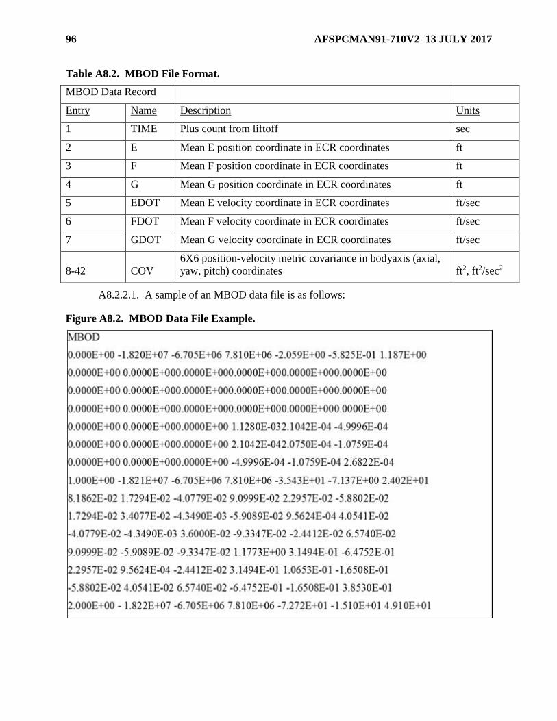
96 AFSPCMAN91-710V2 13 JULY 2017
Table A8.2. MBOD File Format.
MBOD Data Record
Entry Name Description Units
1 TIME Plus count from liftoff sec
2 E Mean E position coordinate in ECR coordinates ft
3 F Mean F position coordinate in ECR coordinates ft
4 G Mean G position coordinate in ECR coordinates ft
5 EDOT Mean E velocity coordinate in ECR coordinates ft/sec
6 FDOT Mean F velocity coordinate in ECR coordinates ft/sec
7 GDOT Mean G velocity coordinate in ECR coordinates ft/sec
8-42 COV
6X6 position-velocity metric covariance in bodyaxis (axial,
yaw, pitch) coordinates ft2, ft2/sec2
A8.2.2.1. A sample of an MBOD data file is as follows:
Figure A8.2. MBOD Data File Example.
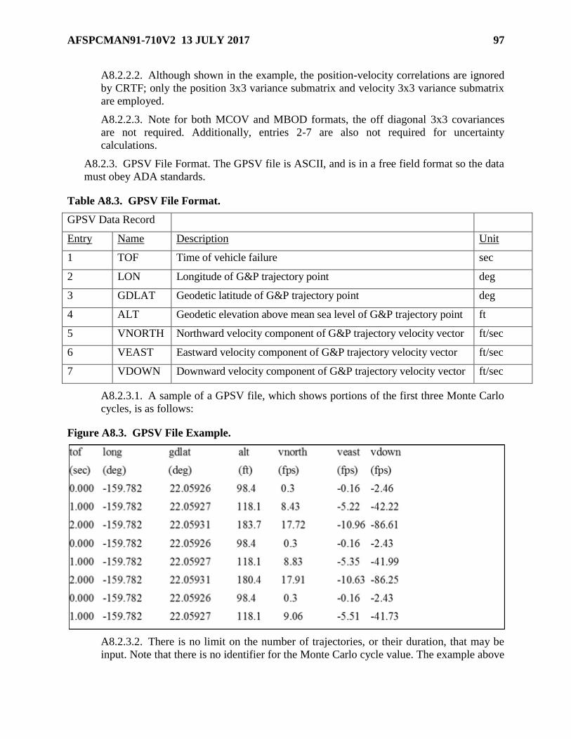
AFSPCMAN91-710V2 13 JULY 2017 97
A8.2.2.2. Although shown in the example, the position-velocity correlations are ignored
by CRTF; only the position 3x3 variance submatrix and velocity 3x3 variance submatrix
are employed.
A8.2.2.3. Note for both MCOV and MBOD formats, the off diagonal 3x3 covariances
are not required. Additionally, entries 2-7 are also not required for uncertainty
calculations.
A8.2.3. GPSV File Format. The GPSV file is ASCII, and is in a free field format so the data
must obey ADA standards.
Table A8.3. GPSV File Format.
GPSV Data Record
Entry Name Description Unit
1 TOF Time of vehicle failure sec
2 LON Longitude of G&P trajectory point deg
3 GDLAT Geodetic latitude of G&P trajectory point deg
4 ALT Geodetic elevation above mean sea level of G&P trajectory point ft
5 VNORTH Northward velocity component of G&P trajectory velocity vector ft/sec
6 VEAST Eastward velocity component of G&P trajectory velocity vector ft/sec
7 VDOWN Downward velocity component of G&P trajectory velocity vector ft/sec
A8.2.3.1. A sample of a GPSV file, which shows portions of the first three Monte Carlo
cycles, is as follows:
Figure A8.3. GPSV File Example.
A8.2.3.2. There is no limit on the number of trajectories, or their duration, that may be
input. Note that there is no identifier for the Monte Carlo cycle value. The example above

98 AFSPCMAN91-710V2 13 JULY 2017
also shows that the start and stop times for each Monte Carlo cycle need not agree. Fewer
cycles at a given time will simply result in weaker statistics when covariance matrices are
generated for each state time using the GPSV data.
Top Related