


Languages
Pages
Legal


20Octob
er2014
SULPHUR TECHNOLOGY MANAGERBLACK & VEATCH ENERGYBILL BRECKENRIDGE
MIDDLE EAST SULPHUR PLANTOPERATIONS FORUM
AGENDAInteractive Discussion
Trends in Overall Plant EmissionsRegional / Global Market Perspectives
Technical TopicsCBA Performance: Improvements & FeedbackOrganic Sulfur in Acid GasContaminated Acid GasDesign Basis

TRENDS IN OVERALLPLANT EMISSIONS
20October 2014
WHAT ARE THE REGIONALTRENDS/OBSERVATIONS?
• 150 mg SO2/Nm3 (dry basis with 3% excessoxygen)• 2007 Environmental Health Standard (EHS)Guidelines for Sulfur Recovery Units inRefineries issued by the InternationalFinance Corporation (“World BankStandard”)
• Commonly used in:• Early project development• Developing countries with no localguidelines
• 750 mg SO2/Nm3 (dry, air free basis)• Roughly 250 ppmv on a dry, air free basis(United States Environmental ProtectionAgency in Part 60, Subpart J. for PetroleumRefineries)
SO2 EMISSION STANDARDS FOR SULFURRECOVERY UNITS
20 October 2014

TYPICAL RECOVERY LEVELS FOR SO2EMISSIONS FROM SULFUR RECOVERY UNITS
20 October 2014
*815C Incinerator Temperature
DRY + 3% OXYGEN DRY + AIR FREE
% Recovery SO2mg/Nm3*
SO2 Stackppmv*
SO2mg/Nm3*
SO2 Stackppmv*
99.97% 150 ~50 180 ~60
99.9% 500 ~165 600 ~200
99.85% 750 ~250 900 ~300
Conventional SRU / TGTU (Amine Based) Design Performance
The trend is lowerand lower emissionrequirements, <150mg/Nm3
CONCLUSIONS:1. Conventional units cannot consistently achieve 50ppmv total sulfur
2. COS remains principal constituent to address
HISTORICAL TGTU PERFORMANCE(CONVENTIONAL REDUCTION / ABSORPTION)
20 October 2014
Absorber Overhead
H2S(ppmv)
COS (ppmv)
CS2(ppmv)
Other (ppmv)
Total(ppmv as S1)
HighPerformance Units
30(<10 to 90)
17(2 to 80)
2(1 to 12)
2(0 to 13)
~50(<10 to 90)
Generic MDEA Units
150(100 to 300)
~175 (100 to 300)
LowPerformance Units
1500(up to 2000)
1500 (up to 2000)

REGIONAL / GLOBALMARKET PERSPECTIVES
20October 2014
REGIONAL GAS SUPPLY/DEMAND &FORECAST FOR NEW SOUR GASDEVELOPMENTS
REGIONAL SULFUR MARKET
GLOBAL GAS MARKETSUPPLY/DEMAND & VIABILITY OFSOUR GAS DEVELOPMENT PROJECTSVS. IMPORTING GAS
TECHNICAL TOPICS

CBA PERFORMANCE:IMPROVEMENTS &FEEDBACK
20October 2014
WHAT ARE THE REGIONALOBSERVATIONS REGARDINGSUBDEWPOINT PERFORMANCE &RELIABILITY?
• CBA process developed by Amoco in 1970s• Achieves higher sulfur recovery than conventionalClaus process (>98.7% vs. 92 96%)
• CBA reactor is a conventional Claus reactoroperated at lower temperature
• CBA reactor operates in “subdewpoint” mode• CBA reactor uses conventional Claus catalyst
SULFUR RECOVERY USING COLD BEDADSORPTION (CBA) PROCESS
20 October 2014

• Cyclical process, CBA reactor alternates adsorptionstep with regeneration step
• There are other similar subdewpoint Clausprocesses; these differ from CBA in method ofregeneration:
• About 35 CBA units have been installed, many innatural gas purification service. Capacities rangefrom 10 TPD – 700 TPD.
SULFUR RECOVERY USING COLD BEDADSORPTION (CBA) PROCESS
20 October 2014
CBA REACTOR SUBDEWPOINTOPERATION
20October 2014
TypicalClaus Reactor
TypicalSubdewpoint Reactor
415° F
450° F
260° F
300° F
Gas inside reactor stays abovesulfur dewpoint as Clausreaction progresses
Gas inside reactor reachessulfur dewpoint as Clausreaction progresses

2 BED CBA—HAS ACHIEVED >99.0%RECOVERY
20 October 2014
SULFUR
CBACONDENSER
CLAUSCONDENSER
CLAUSREACTOR
CBAREACTOR
NO. 1
CBAREACTOR
NO. 2
FROM1ST
CONDENSER
TAIL GASTOINCINERATOR
STEAM STEAM
1st 2nd
3 BED CBA—HAS ACHIEVED >99.2%RECOVERY
20 October 2014
SULFUR
CBACOND. NO. 1
CLAUSCONDENSER
CBACOND. NO. 2
CBACOND. NO. 3
CLAUSREACTOR
CBAREACTOR
NO. 1
CBAREACTOR
NO. 2
CBAREACTOR
NO. 3
FROM1ST
CONDENSER
TAIL GASTO
INCINERATOR
STEAM STEAM STEAM STEAM
1st 2nd 3rd
ONE COMPLETE 2 REACTOR CBA CYCLE
20 October 2014
200
250
300
350
400
450
500
550
600
650
700
4:00
5:00
6:00
7:00
8:00
9:00
10:00
11:00
12:00
13:00
14:00
15:00
16:00
17:00
18:00
19:00
20:00
21:00
22:00
23:00
0:00
1:00
Tempe
rature,°
F
JUST INLET TEMPERATURESAND INCINERATOR SO2 CONCENTRATION
20October 2014
0
1000
2000
3000
4000
5000
200
300
400
500
600
700
12:00
0:00
12:00
0:00
12:00
0:00
Incine
ratorS
O2,pp
mv
Tempe
rature,°
F

• Apply 3 improvements:1. Use a better CBA reactor rotation sequence to avoid
SO2 emissions spikes, improving sulfur recoveryefficiency
2. Use an improved condenser arrangement, requiringonly 3 condensers instead of 4
3. With improved condenser arrangement, operate lastbed at cooler temperature, get better sulfur recoveryefficiency
CAN IMPROVE 3 BED CBA SULFURRECOVERY EFFICIENCY
20 October 2014
• Past 3 bed designs considered catalyst sulfurloadings, sequenced reactors from most loaded toleast loaded
• Better to consider temperature instead of loading,sequencing reactors from highest temperature tolowest temperature
• Catalyst temperature has greater effect on sulfurrecovery efficiency than does catalyst sulfur loading
BETTER 3 BED CBA REACTOR ROTATIONSEQUENCE
20 October 2014

REVISED 3 BED CBA SEQUENCE
20 October 2014
1st 2nd 3rd
1st 2nd 3rd
Old Sequence:(Stages Loadings)
New Sequence:(Stages Temps.)
• Adopt a reactor condenser arrangement wherereactor and upstream condenser switch in sequenceas a unit
• Only 3 condensers required instead of 4• 2 more switching valves required• Facilitates operation of last condenser at coolertemperature
NEXT, IMPROVE 3 BED CBA CONDENSERARRANGEMENT
20 October 2014

3 BED CBA—REACTOR SWITCHES AS UNITWITH UPSTREAM CONDENSER
20 October 2014
1st 2nd 3rd
CBACOND. NO. 1
CLAUSREACTOR
CBAREACTOR
NO. 1
FROM1ST
CONDENSER
STEAM
CBACOND. NO. 2
STEAM
CBAREACTOR
NO. 2
CBACOND. NO. 3
STEAM
CBAREACTOR
NO. 3
SULFUR
TAIL GASTOINCINERATOR
150
200
250
300
350
400
450
500
12:00
0:00
12:00
0:00
12:00
Tempe
rature,°
F
Time, Hours
EXPECTED LAST REACTOR OUTLETTEMPERATURE PROFILES
20 October 2014
2 Bed
3 Bed
3 Bed, Better Rotation3 Bed, Better Rotation, Cooler Temperature

CALCULATED SULFUR RECOVERY EFFICIENCYCOMPARISON FOR NEW 3 BED CBA SCHEME—41% H2S IN ACID GAS FEED
Step Duration(hr)
Sulfur RecoveryEfficiencyPrior 3 Bed
Sulfur RecoveryEfficiencyImproved 3 Bed
Precool 3.0 99.36% 99.52%
Final Cool 3.0 99.43% 99.55%
Heat Up 4.1 99.43% 99.55%
Plateau 1.4 99.35% 99.60%
Heat Soak 1.9 99.45% 99.64%
Overall Averagefor Cycle
13.4 99.41% 99.56%
20 October 2014
• Improved 3 Bed CBA performance (B&V Patent)• Better CBA reactor rotation sequence• Better sulfur condenser arrangement• Cooler last CBA reactor
• No performance data yet• Can test performance improvements in existing 3Bed CBA units, without plant modifications
• Expect 0.15% improvement in sulfur recoveryefficiency—a 25% reduction in SO2 emissions
• Reliable CBA operation at >99.5% cycle averagesulfur recovery efficiency appears within reach, witha cost effective flowsheet
CBA IMPROVEMENT SUMMARY
20 October 2014
SULFUR RECOVERY FOR CLAUS AND CBA DESIGNS
20 October 2014
H2S Concentration in Acid Gas, Mole Percent
Sulfu
r Rec
over
y Ef
ficie
ncy,
Per
cent
0
96
98
100
40 8094
99
97
95
3 Reactor Claus
4 Reactor Claus
CBA 3 ReactorCBA 4 Reactor
20 60 100
Higher SRU recovery by CBAconfiguration may eliminate redundantTGTU sparing requirements
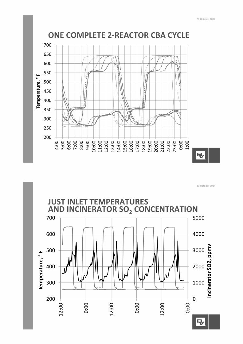
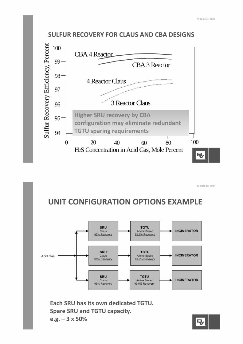
UNIT CONFIGURATION OPTIONS EXAMPLE
20 October 2014
Each SRU has its own dedicated TGTU.Spare SRU and TGTU capacity.e.g. – 3 x 50%

UNIT CONFIGURATION OPTIONS EXAMPLE
20 October 2014
Make each TGTU slightly larger, and eliminateone unit. Spare SRU and TGTU capacity. Somepiping / control complications.e.g. – 3 x 50% SRUs, 2 x 100% TGTUs
UNIT CONFIGURATION OPTIONS EXAMPLE
20 October 2014
Convert each SRU to subdewpoint. Based on~99% recovery, eliminate the requirement forspare TGTU capacity.e.g. – 3 x 50% SRU, 1 x 100% TGTU
Each project will have uniquecircumstances governing /limiting the unit size, recoveryand sparing approach.
ORGANIC SULFUR IN FEEDGAS
20October 2014
HOW OFTEN IS COS/RSH PRESENT INYOUR ACID GAS?
HOW DOES THIS IMPACT EMISSIONS,PARTICULARLY WITH ACID GASENRICHMENT?
DESI
GN
CHALL
ENGES
• For AGE facilities, COS and mercaptans (RSH) contributedirectly to emissions because they tend to slip throughAGE Absorber• COS comes from upstream AGRU that is normally designedto remove all COS (also coabsorbs abundant CO2)
• Mercaptans depend on upstream, AGRU solvent selectionand sophistication of model
• Predicting performance of organic sulfur absorption iscomplex and challenging, particularly at low pressuresand in the presence of H2S• Heavily dependent on accuracy of solvent vendorperformance data to meet emissions
ORGANIC SULFUR IN FEED GAS20 October 2014
Cannot decouple AGRU and SRU Performance!!

1. Diversion of inlet feed gas to TGTU, which contains areducing section that will hydrolyze mercaptans andCOS (no AGE Absorber)
OPTIONS TO MITIGATE ORGANIC SULFUR INFEED GAS – SULFUR BLOCK MODIFICATION
20October 2014
DESI
GN
CHALL
ENGES
2. Diversion of AGE Absorber overhead to TGTU usingsemi rich solvent in AGE Absorber (B&V Patent)
OPTIONS TO MITIGATE ORGANIC SULFUR INFEED GAS – SULFUR BLOCK MODIFICATION
20October 2014
DESI
GN
CHALL
ENGES

3. Interstage cooling and hydrolysis in the AGRU tomaximize CO2 slip and hydrolyze COS (B&V designfrom Sinopec Puguang Natural Gas Treating Project)
OPTIONS TO MITIGATE ORGANIC SULFUR INFEED GAS – UPSTREAMMODIFICATION
20October 2014
DESI
GN
CHALL
ENGES
4. Tail Gas Scrubbing (Caustic Scrubber)• Last resort if integration with AGRU or project optimizationcannot be achieved
• Challenges with tail gas scrubbing• Wastewater disposal or treatment• High alloy metallurgy• Cost (Opex) and delivery logistics of caustic
• Tail gas scrubbing represents a trade of air emissions forliquid emissions or costly wastewater treatment
OPTIONS TO MITIGATE ORGANIC SULFUR INFEED GAS – DOWNSTREAMMODIFICATION
20October 2014
DESI
GN
CHALL
ENGES

CONTAMINATED ACIDGAS
20October 2014
HOW OFTEN IS BTX A COMPONENT INACID GAS?
HAS IT BEEN A PROBLEM?
WHAT ARE YOUR MITIGATIONMEASURES?
• Uncertainty in BTX contained in Produced Gas• Uncertainty in BTX pickup by AGRU solvent• BTX has to be removed or destroyed prior to cominginto contact with any catalyst bed
• Lean acid gases often do not burn hot enough forsufficient BTX destruction in the SRU ThermalReactor
BTX IN FEED GAS
20 October 2014
DESI
GN
CHALL
ENGES

DESI
GN
CHALL
ENGES
• Lean Acid Gas (<45% H2S) + COS/RSH + BTX + Ultra LowEmissions (<150 mg SO2/Nm3) = Difficult Challenge toProcess
• In addition to ultra low emissions, some projects arerequiring a minimal level of SRU recovery• Requirements >95% will require 3rd catalytic stage or moreelaborate design
CONTAMINATED LEAN ACID GAS
20 October 2014
DESI
GN
CHALL
ENGES
• Often significant technical challenges and uncertaintywith lean acid gas feeds and ultra low emissions
• Sizeable commercial and operational impacts forachieving ultra low emissions
• Design optimization requires joint effort andcooperation between designers, end users andregulatory agencies
CONTAMINATED LEAN ACID GAS
20 October 2014
• Alternative options to destroy BTX• Thermal Reactor temperature enhancements:
• Oxygen enrichment – unattractive if oxygen notreadily available. Higher Opex.
• Co firing natural gas – not recommend, trades onecatalyst contaminant (BTX) for another (soot)
• Acid Gas Enrichment to improve acid gas quality• Upstream BTX removal – Sorbead™ Quick Cycleprocess (silica gel based absorbent that removes BTXwith heavier hydrocarbons, also removes mercaptans)
• Carbon beds upstream of SRU (developed by SaudiAramco)
BTX IN FEED GAS
20 October 2014
DESI
GN
CHALL
ENGES
DESIGN BASIS20October 2014
WHAT IS YOUR APPROACH TO SETTINGDESIGN PARAMETERS GAS TREATINGDURING EARLY PROJECTDEVELOPMENT?ARE YOU THINKING ABOUTCOS/RSH/BTX?WHAT ARE LONG TERMPERFORMANCE REQUIREMENTS?

DESI
GN
CHALL
ENGES
• Important components that need to be adequatelydefined:• Organic Sulfur Species – complicate achieving ultra lowemissions• Carbonyl Sulfide (COS) and/or mercaptans (RSH)
• Contaminants – potential catalyst deactivation• Benzene, Toluene, Xylene (BTX)
DESIGN BASIS – FEED COMPOSITION
20 October 2014
DESI
GN
CHALL
ENGES
• Upstream modifications can reduce organic sulfur andBTX content in acid gas feed to SRU
• Being able to integrate and optimize upstreammodifications with SRU design is often complicated• It is difficult for SRU designed to influence overall design ofupstream units that may or may not be in SRU designersscope
• If design can be integrated and optimized across all unitinterfaces, it will result in an overall project WIN in termsof OPEX/CAPEX
DESIGN BASIS – UPSTREAMMODIFICATIONS
20 October 2014

DESI
GN
CHALL
ENGES
• Typically contractors focus on start of run (SOR)guarantees
• Projects with lean acid gases and ultra low emissionsmay have some exposure to performances shortcomingsat end of run (EOR)
• Technology provider and Owner should focus onmaximizing performance at EOR and not just meetingguarantees
DESIGN BASIS – SOR VS. EOR
20 October 2014
www.bv.com
Top Related