


Languages
Pages
Legal

1
Mauro NataliniDeputy Manager - Valve Engineering Dept.
REMOSACagliari, Italy
Tel +39.070.2020237 / Mob [email protected] www.remosa-valves.com
FCC Special ValvesBest Practices to Increase
Performance, Reliability & Service Life

2
- REMOSA brief introduction
- IMI Severe Service Organization
- FCC Special Valves and Plant Layouts
- Case Studies (Slide Valves, Diverter Valve, VO Valve)
- Engineering Advantage and Technical Services
- Best Practice for Turnaround and Commissioning
Lifting a Diverter Valve
OVERVIEW
3
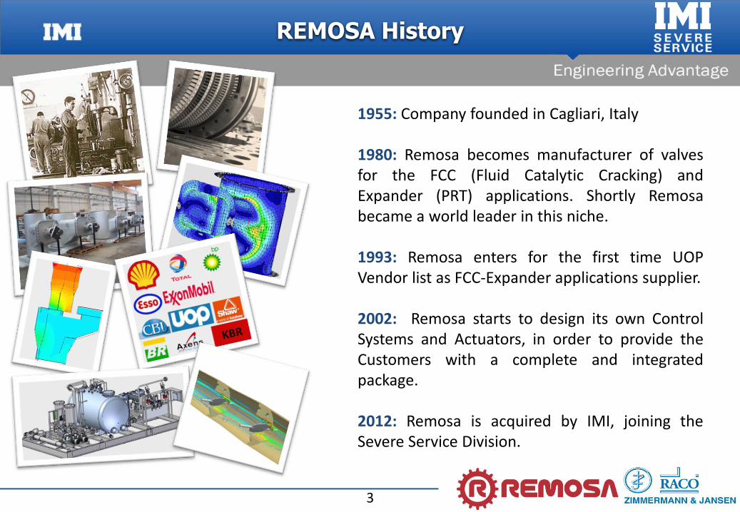
1955: Company founded in Cagliari, Italy
1980: Remosa becomes manufacturer of valvesfor the FCC (Fluid Catalytic Cracking) andExpander (PRT) applications. Shortly Remosabecame a world leader in this niche.
1993: Remosa enters for the first time UOPVendor list as FCC-Expander applications supplier.
2002: Remosa starts to design its own ControlSystems and Actuators, in order to provide theCustomers with a complete and integratedpackage.
2012: Remosa is acquired by IMI, joining theSevere Service Division.
REMOSA History
4
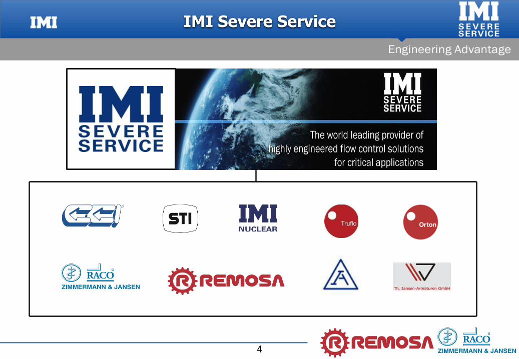
IMI Severe Service
5
1B
1A8
Air
67
CatalystWithdrawal
1C
2
Wet Gas / LPG
Naphtha / Gasoline
LCO / Middle Distillate
HCO / Fuel Oil
PumpAround
BottomResidual
BottomDischarge
Pumps
Pumps
5
5
5
5
5
5
5
5
5
2
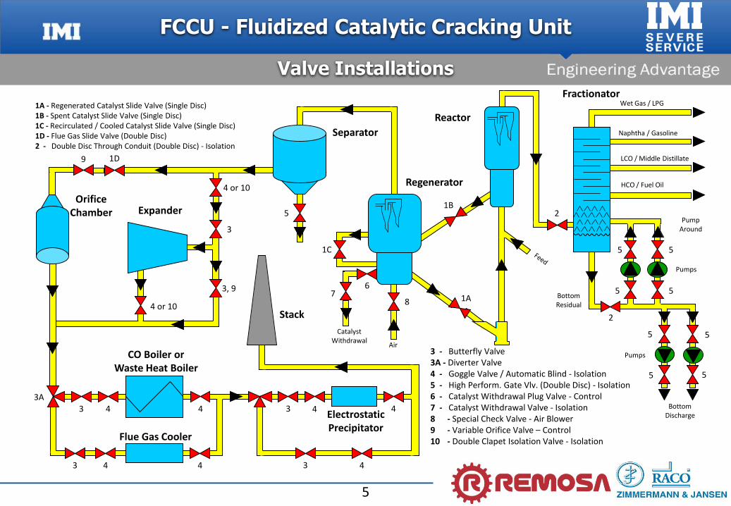
3 - Butterfly Valve3A - Diverter Valve4 - Goggle Valve / Automatic Blind - Isolation5 - High Perform. Gate Vlv. (Double Disc) - Isolation6 - Catalyst Withdrawal Plug Valve - Control7 - Catalyst Withdrawal Valve - Isolation8 - Special Check Valve - Air Blower9 - Variable Orifice Valve – Control10 - Double Clapet Isolation Valve - Isolation
3
1D
4 or 10
3
4 or 10
3, 9
Reactor
Regenerator
Fractionator
Separator
ExpanderOrifice
Chamber
Stack
ElectrostaticPrecipitator
CO Boiler orWaste Heat Boiler
Flue Gas Cooler
3
4
4
4
4
3A43
3 4
4
1A - Regenerated Catalyst Slide Valve (Single Disc)1B - Spent Catalyst Slide Valve (Single Disc)1C - Recirculated / Cooled Catalyst Slide Valve (Single Disc)1D - Flue Gas Slide Valve (Double Disc)2 - Double Disc Through Conduit (Double Disc) - Isolation
9
FCCU - Fluidized Catalytic Cracking Unit
Valve Installations

6
FCCU - Fluidized Catalytic Cracking Unit
REMOSA / Z&J Products
Slide Valve (Single Disc)
Slide Valve (Double Disc)
Butterfly Valve(PRT, Flue Gas Bypass)
Double Clapet ExpanderIsolation Valve
Double Disc ThroughConduit Isolation Valve
Goggle Valve / AutomaticBlind Isolation Valve
Special Check Valve
Actuating / Control Systems
Diverter Valve (Pendulum Type)
Diverter Valve (Linear Type & Flip-Flop)
Variable Orifice Valve(PRT, Flue Gas Bypass)
Plug Valve
Catalyst WithdrawalValve
High PerformanceGate Valve
Special CustomizedEquipments
Remote PLC Cabinets(for FCC, DC, Catofin, others)
7
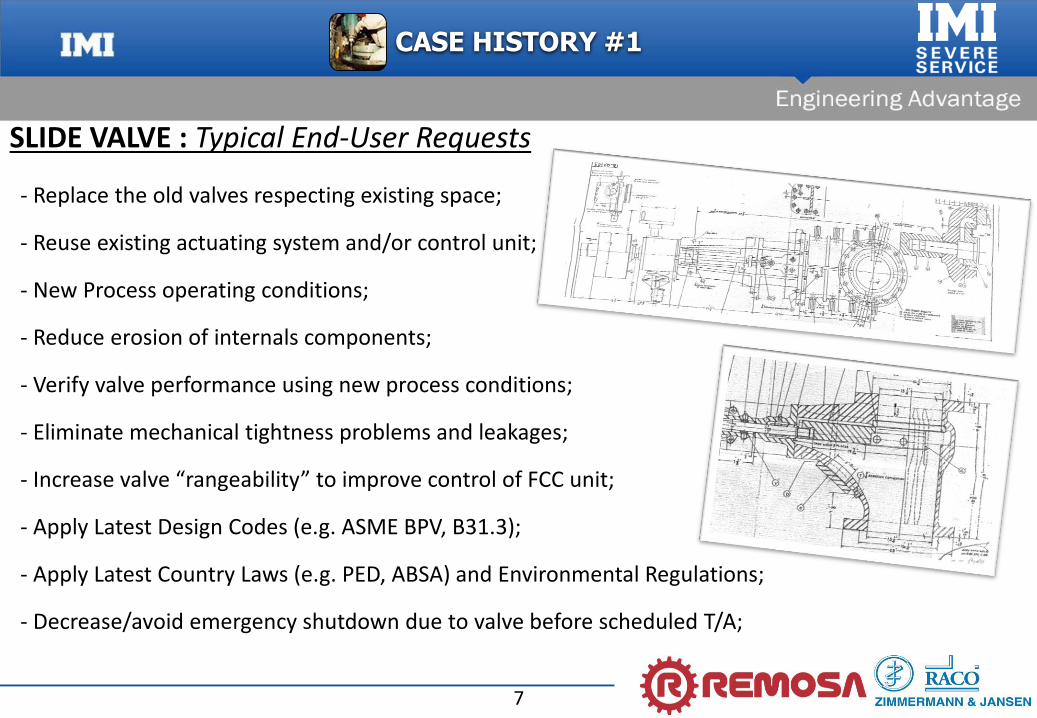
SLIDE VALVE : Typical End-User Requests
- Replace the old valves respecting existing space;
- Reuse existing actuating system and/or control unit;
- New Process operating conditions;
- Reduce erosion of internals components;
- Verify valve performance using new process conditions;
- Eliminate mechanical tightness problems and leakages;
- Increase valve “rangeability” to improve control of FCC unit;
- Apply Latest Design Codes (e.g. ASME BPV, B31.3);
- Apply Latest Country Laws (e.g. PED, ABSA) and Environmental Regulations;
- Decrease/avoid emergency shutdown due to valve before scheduled T/A;
CASE HISTORY #1
8
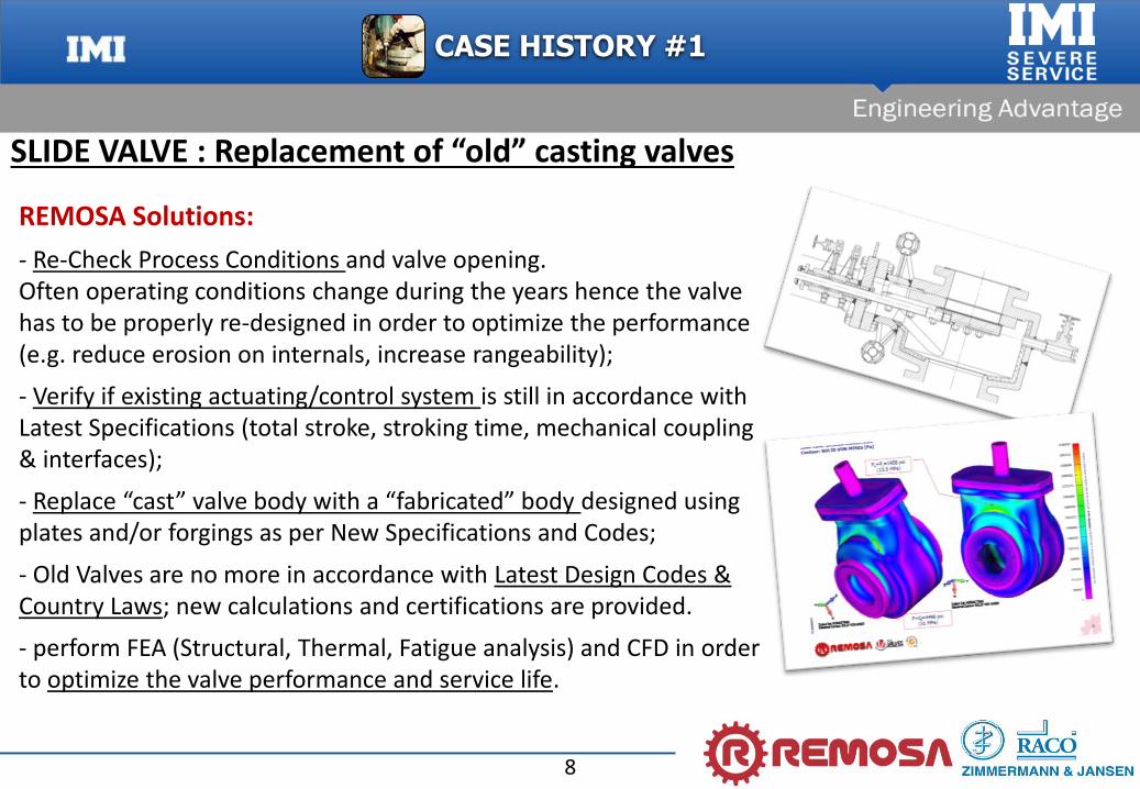
REMOSA Solutions:
- Re-Check Process Conditions and valve opening. Often operating conditions change during the years hence the valve has to be properly re-designed in order to optimize the performance (e.g. reduce erosion on internals, increase rangeability);
- Verify if existing actuating/control system is still in accordance with Latest Specifications (total stroke, stroking time, mechanical coupling & interfaces);
- Replace “cast” valve body with a “fabricated” body designed using plates and/or forgings as per New Specifications and Codes;
- Old Valves are no more in accordance with Latest Design Codes & Country Laws; new calculations and certifications are provided.
- perform FEA (Structural, Thermal, Fatigue analysis) and CFD in order to optimize the valve performance and service life.
CASE HISTORY #1
SLIDE VALVE : Replacement of “old” casting valves
9
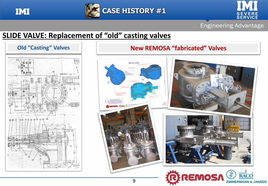
SLIDE VALVE: Replacement of “old” casting valves
Old “Casting” Valves New REMOSA “fabricated” Valves
CASE HISTORY #1

10
SLIDE VALVE: “…have more Service Life ! ”
- Existing Valve (not manufactured by REMOSA) had “sticking” problems due to wrong Cold Set Clearances between Disc and Orifice Plate.
- Cold vertical clearances were not enough large to prevent the contact between disc and
orifice plate during the emergency trip condition.
- REMOSA changed the design in order to avoid contacts and increase reliability of the new valve.
Original ValveOriginal Cold vertical clearances between internal sliding parts
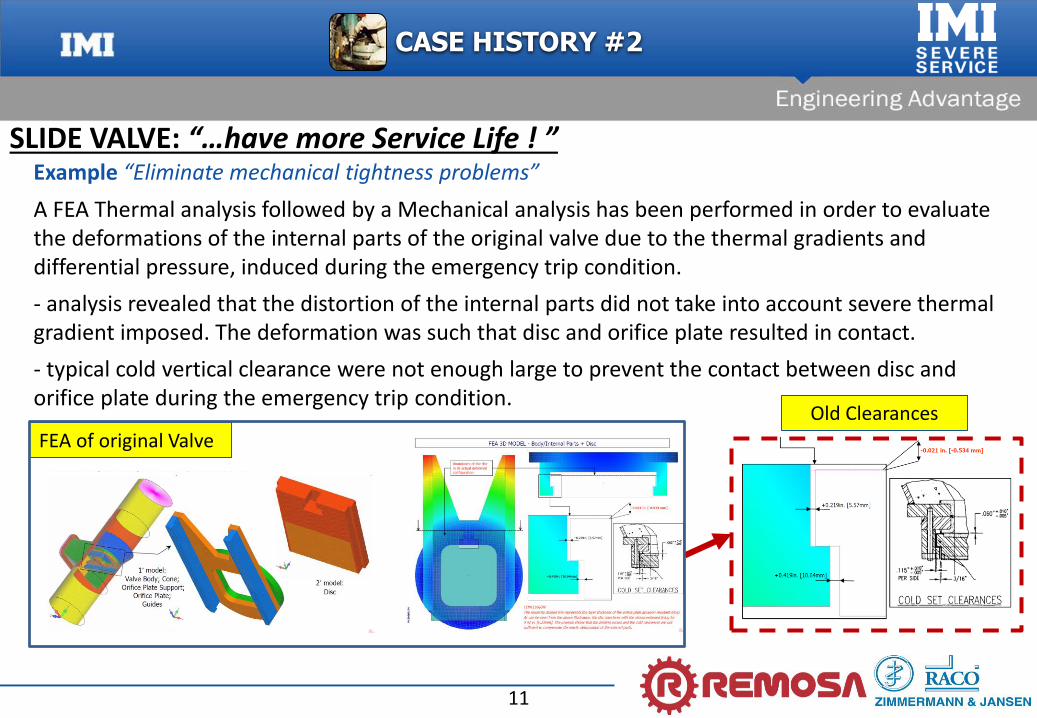
Example “Eliminate mechanical tightness problems”
CASE HISTORY #2
11
A FEA Thermal analysis followed by a Mechanical analysis has been performed in order to evaluate the deformations of the internal parts of the original valve due to the thermal gradients and differential pressure, induced during the emergency trip condition.
- analysis revealed that the distortion of the internal parts did not take into account severe thermal gradient imposed. The deformation was such that disc and orifice plate resulted in contact.
- typical cold vertical clearance were not enough large to prevent the contact between disc and orifice plate during the emergency trip condition.
SLIDE VALVE: “…have more Service Life ! ”Example “Eliminate mechanical tightness problems”
FEA of original Valve
Old Clearances
CASE HISTORY #2

12
REMOSA Solution:
- Opening modified as per New Customer Specifications;
- FEA of the new Valve to evaluate the deformations of the internal parts of the valve due to the thermal gradients and differential pressure, induced during the upstream high emergency condition;- Vertical cold clearances increased to take into account emergency condition.
SLIDE VALVE: “…have more Service Life ! ”
FEA of “New” Valve
New Clearances
CASE HISTORY #2

13
CASE HISTORY #3
SLIDE VALVE: “Revamping an old valve during the T/A”
Old Valve (Not Manufactured by REMOSA)
The guides were “fixed” to the bonnet !

14
CASE HISTORY #3
SLIDE VALVE: “Revamping an old valve during the T/A”
Old Valve (Not Manufactured by REMOSA)
Disc
Guides
Guide bolts protection cuttingOrifice Plate cutting
Orifice Plate
15
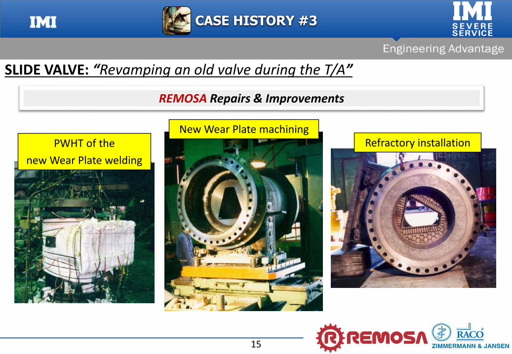
CASE HISTORY #3
SLIDE VALVE: “Revamping an old valve during the T/A”
REMOSA Repairs & Improvements
PWHT of the
new Wear Plate welding
New Wear Plate machiningRefractory installation
16
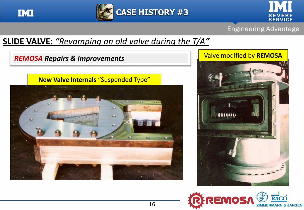
CASE HISTORY #3
SLIDE VALVE: “Revamping an old valve during the T/A”
REMOSA Repairs & Improvements
New Valve Internals “Suspended Type”
Valve modified by REMOSA

17
ORIFICE CHAMBER vs VARIABLE ORIFICE VALVE
3D of VO Valve
VO Valve Installed
CASE HISTORY #4
18
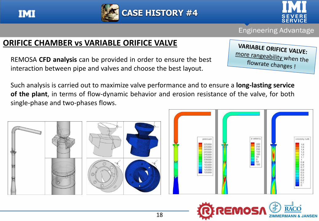
REMOSA CFD analysis can be provided in order to ensure the bestinteraction between pipe and valves and choose the best layout.
CASE HISTORY #4
ORIFICE CHAMBER vs VARIABLE ORIFICE VALVE
Such analysis is carried out to maximize valve performance and to ensure a long-lasting serviceof the plant, in terms of flow-dynamic behavior and erosion resistance of the valve, for bothsingle-phase and two-phases flows.
19
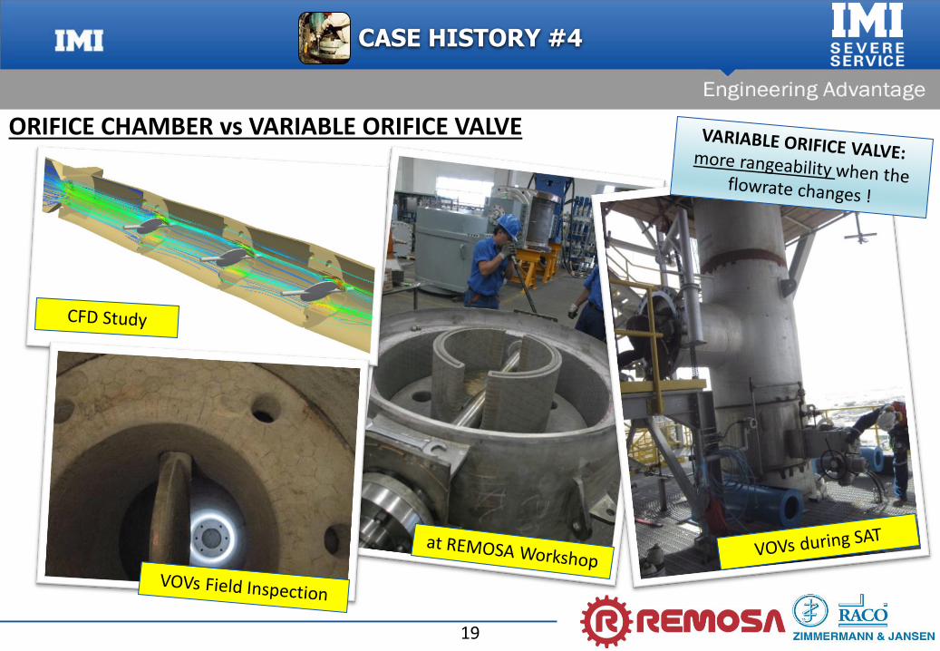
CASE HISTORY #4
ORIFICE CHAMBER vs VARIABLE ORIFICE VALVE

20
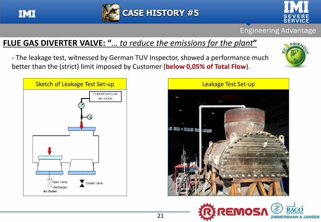
FLUE GAS DIVERTER VALVE: “… to reduce the emissions for the plant”
- Flue Gas Diverter Valve, linear design;
- The diverter valve control the flow coming from third stage separator directing it to the CO Boiler or to a bypass stack;
- Enviromental Regulations are constantly decreasing the emissions limits for the plants, so also for these valves;
- Due to the poor performance of the existing diverter (not supplied by Remosa) the Customer asked Remosa to design and manufacture a new diverter valve able to meet an extremely low leakage limit (below 0,05% of Total Flow);
CASE HISTORY #5
21
Leakage Test Set-upSketch of Leakage Test Set-up
- The leakage test, witnessed by German TUV Inspector, showed a performance much better than the (strict) limit imposed by Customer (below 0,05% of Total Flow).
FLUE GAS DIVERTER VALVE: “… to reduce the emissions for the plant”
CASE HISTORY #5
22
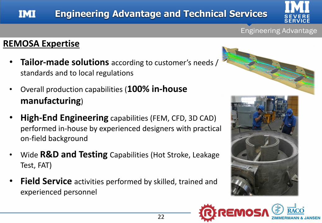
• Tailor‐made solutions according to customer’s needs /
standards and to local regulations
• Overall production capabilities (100% in-house manufacturing)
• High‐End Engineering capabilities (FEM, CFD, 3D CAD)
performed in‐house by experienced designers with practical on‐field background
• Wide R&D and Testing Capabilities (Hot Stroke, Leakage
Test, FAT)
• Field Service activities performed by skilled, trained and
experienced personnel
Engineering Advantage and Technical Services
REMOSA Expertise
23
Turnaround Strategies & Best Practice
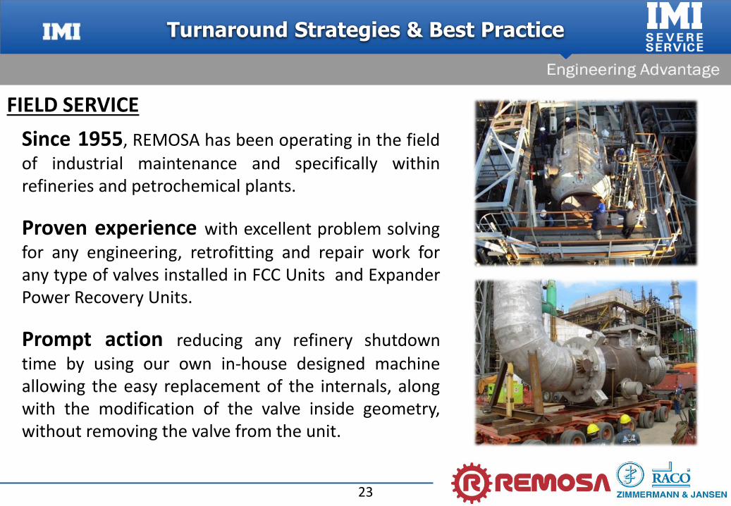
FIELD SERVICE
Since 1955, REMOSA has been operating in the field
of industrial maintenance and specifically withinrefineries and petrochemical plants.
Proven experience with excellent problem solving
for any engineering, retrofitting and repair work forany type of valves installed in FCC Units and ExpanderPower Recovery Units.
Prompt action reducing any refinery shutdown
time by using our own in-house designed machineallowing the easy replacement of the internals, alongwith the modification of the valve inside geometry,without removing the valve from the unit.
24
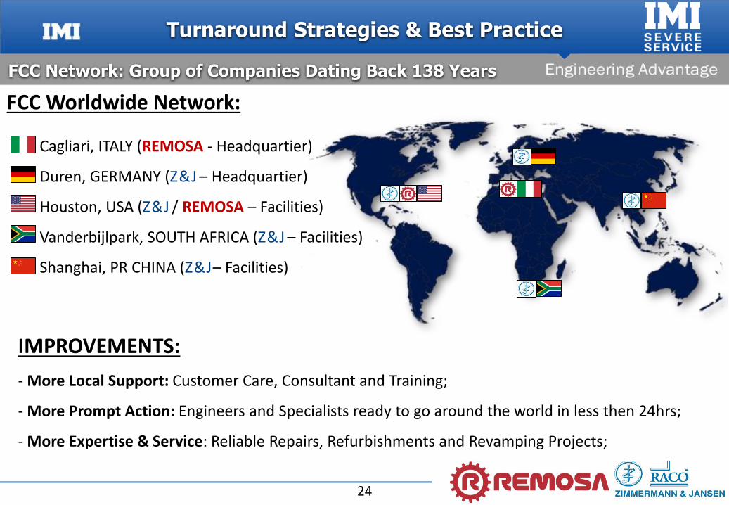
Cagliari, ITALY (REMOSA - Headquartier)
Duren, GERMANY (Z & J – Headquartier)
Houston, USA (Z & J / REMOSA – Facilities)
Vanderbijlpark, SOUTH AFRICA (Z & J – Facilities)
Shanghai, PR CHINA (Z & J– Facilities)
FCC Worldwide Network:
IMPROVEMENTS:
- More Local Support: Customer Care, Consultant and Training;
- More Prompt Action: Engineers and Specialists ready to go around the world in less then 24hrs;
- More Expertise & Service: Reliable Repairs, Refurbishments and Revamping Projects;
FCC Network: Group of Companies Dating Back 138 Years
Turnaround Strategies & Best Practice

25
INCREASINGPLANT PROFIT
MINIMIZING TOTAL DOWNTIME
MAINTAINING RELIABLE PERFORMANCE
MAXIMIZING ELAPSED TIME BETWEEN TURNAROUNDS
PREDICTIVE MAINTENANCE
INCREASING PLANT PERFORMANCE
FIELD SERVICE
Turnaround Strategies & Best Practice
26
Plan the turnaround, with a qualified valve/control system manufacturer, no later than 6 months prior to the scheduled shutdown
Review the report from the previous turnaround (if available)
Inspect the spare parts in stock and record their existing condition
Walk through the unit and identify each valve/actuator and their location to determinenecessary manpower and equipment required
Discuss any operation problems (recorded or not recorded) with the valves/actuators (if any)
Evaluate current process against current design
Discuss customer’s expectation for the upcoming shutdown
Review customer safety plans, trainings and T/A scheduling
MINIMIZING TOTAL DOWNTIME
FIELD SERVICE
Turnaround Strategies & Best Practice
27
• Recommendation for the necessary level of spare parts must have “on hand” for the Turnaround
• Proposed Turnaround procedure
• Definition of Valve Contractor work
• Definition of Valve Contractor responsibility
• Planning and Scheduling of Turnaround activities
No surprises when the Turnaround starts !
MINIMIZING TOTAL DOWNTIME
FIELD SERVICE
Turnaround Strategies & Best Practice
28
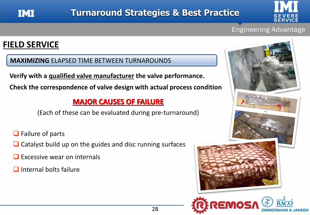
Verify with a qualified valve manufacturer the valve performance.
Check the correspondence of valve design with actual process condition
MAJOR CAUSES OF FAILURE
(Each of these can be evaluated during pre-turnaround)
Failure of parts
Catalyst build up on the guides and disc running surfaces
Excessive wear on internals
Internal bolts failure
MAXIMIZING ELAPSED TIME BETWEEN TURNAROUNDS
FIELD SERVICE
Turnaround Strategies & Best Practice
29
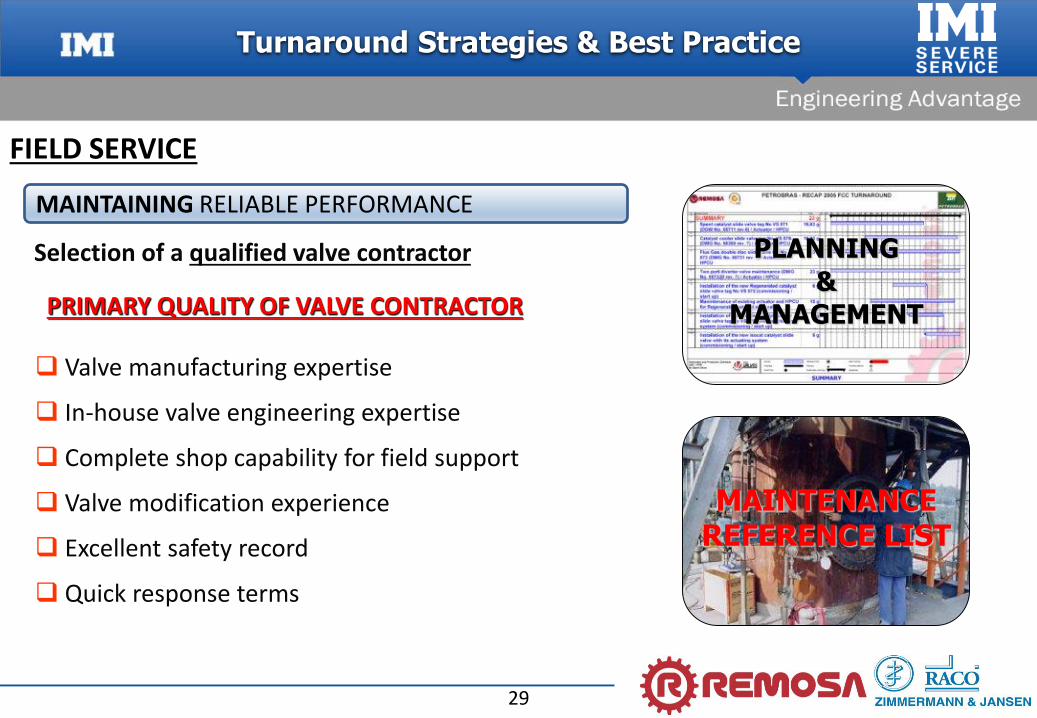
Selection of a qualified valve contractor
PRIMARY QUALITY OF VALVE CONTRACTOR
Valve manufacturing expertise
In-house valve engineering expertise
Complete shop capability for field support
Valve modification experience
Excellent safety record
Quick response terms
PLANNING
&
MANAGEMENT
MAINTAINING RELIABLE PERFORMANCE
MAINTENANCEREFERENCE LIST
FIELD SERVICE
Turnaround Strategies & Best Practice
30
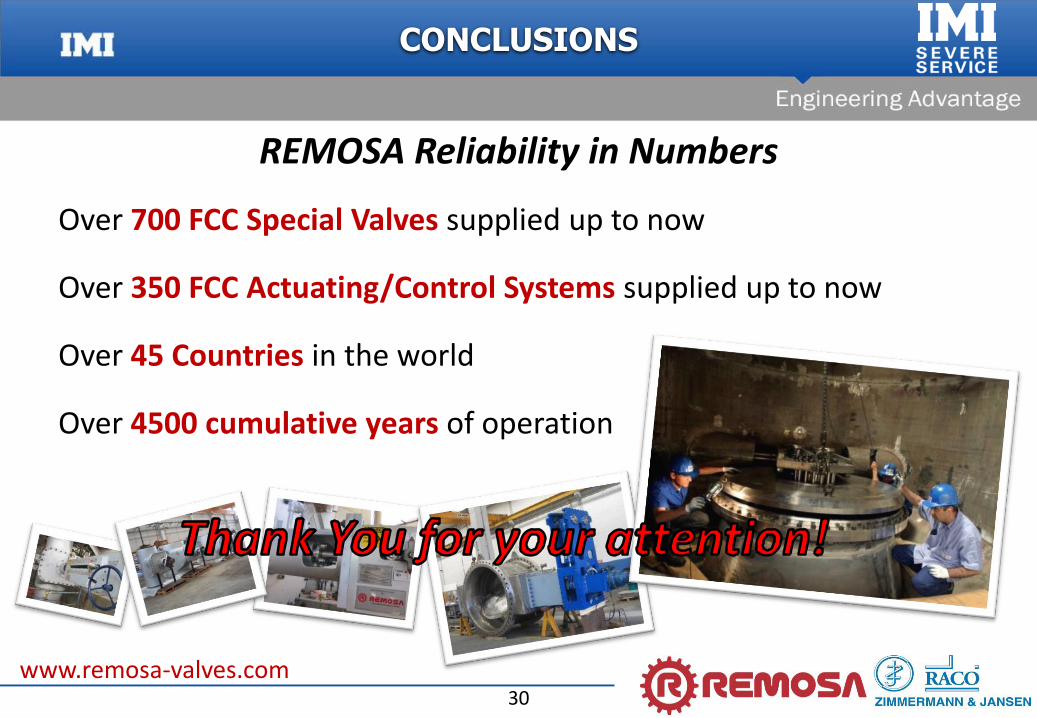
Over 700 FCC Special Valves supplied up to now
Over 350 FCC Actuating/Control Systems supplied up to now
Over 45 Countries in the world
Over 4500 cumulative years of operation
REMOSA Reliability in Numbers
CONCLUSIONS
www.remosa-valves.com
Top Related