


Languages
Pages
Legal


BARTON® MODEL 202EDIFFERENTIAL PRESSURE
RECORDERS
User ManualPart No. 9A-10060, Rev. 02
March 2009
Contents
Safety Information .......................................................................................... 2Section 1—Introduction ................................................................................. 3
General ......................................................................................................... 3Main Components ......................................................................................... 3
Section 2—Installation/Calibration Check ................................................... 9General ......................................................................................................... 9Calibration Check........................................................................................ 10Recorder Mounting .................................................................................... 12Piping .......................................................................................................... 13Electrical Connections ................................................................................ 13Chart Installation ......................................................................................... 13Startup ....................................................................................................... 13Operation .................................................................................................... 14
Section 3—Maintenance and Calibration ................................................... 15Maintenance ............................................................................................... 15Differential Pressure Pen Calibration .......................................................... 15Adding Counterweight to #2 Pen (DP) ........................................................ 17Static Pressure Pen Calibration .................................................................. 19Static Pressure Element Replacement ....................................................... 21Chart Drive Replacement............................................................................ 21Linkage Adjustments ................................................................................... 22DPU Replacement ...................................................................................... 23DPU Cleaning and Inspection ..................................................................... 24Change of DPU Range ............................................................................... 27Setting Bellows Travel................................................................................. 30Bellows Unit Assembly (BUA) Replacement ............................................... 30
Section 4—Troubleshooting ........................................................................ 33Section 5—Installation/Dimensional Drawings ......................................... 37
Model 202E (Part No. 9A-0202-101.3) ....................................................... 37Model 202E w/Temperature Element (Part No. 9A-0202-1011.3) ............... 39Model 199 DPU (Part No. 9A-0199.0903.3) ............................................... 41

22
Safety Information
Before installing this instrument, become familiar with the installation in-structions in Section 2.
! WARNING:Thissymbolidentifiesinformationaboutpracticesorcircum-stancesthatcanleadtopersonalinjuryordeath,propertydamage,oreconomic loss.
CAUTION: Indicatesactionsorprocedureswhichifnotperformedcorrectlymayleadtopersonalinjuryorincorrectfunctionoftheinstrumentorconnectedequipment.
IMPORTANT: Indicates actions or procedures which may affect instrument operation or may lead to an instrument response that is not planned.
Contents (cont'd)Section 6—Assembly Drawings and Parts Lists ....................................... 43
202E Recorder ............................................................................................ 43199 DPU Assembly ..................................................................................... 49Instrument Specifications ............................................................................ 52Product Warranty ........................................................................................ 55

3
202E Differential Pressure Recorder Section 1
Section 1—Introduction
GeneralThe Barton Model 202E Differential Pressure Recorder measures and records system operation parameters, including gas and liquid flow rate, liquid level in a vessel, and other system variables that can be measured by differential pressure and static pressure methods.
MainComponents
Figure 1.1—202E recorder components
Differential Pressure Unit
The Barton Model 199 Differential Pressure Unit (DPU) shown in Figure 1.1 actuates the recorders. The DPU is a dual bellows assembly enclosed within pressure housings. The bellows are liquid-filled and withstand overranges equal to the working pressure of the housing without calibration change. Movement of the bellows is transmitted through a torque tube from the DPU

4
Section 1 202E Differential Pressure Recorder
to the recording mechanism. The torque tube is hermetically sealed to elimi-nate friction and leakage; it does not require lubrication.
The DPU is attached to the back of the recorder case. The torque tube is inserted through a hole in the case and connected to the DP drive arm of the recorder mechanism. Movement of the bellows is transmitted by the DPU drive arm to the torque tube as a rotary motion, which in turn rotates the re-corder mechanism. The pressure housings of the DPU are connected by pipe or tubing to the high- and low-pressure sides of the primary device located in the process system.
The range of the DPU is determined by the force required to move the bel-lows through their normal range of travel. The range springs, which are avail-able in various ranges, balance the DP applied to the unit (see bellows unit assemblies in Figure 1.2 and Figure 1.3, page 5). The number of springs and their ratings vary with individual DP range requirements.
Drive ArmHole Plug
(Do Not Loosen)
Range Springs
Lock Nut
Push Rod
Retainer Screws
Torque TubeGland Nut
(Do Not Loosen)
Torque Tube Shaft
Range Spring Assembly
Figure 1.2—Bellows unit assembly (2 1/8-in.)

5
202E Differential Pressure Recorder Section 1
Range Springs
Torque TubeGland Nut
(Do Not Loosen)
Torque TubeShaft
Lock Nut
Push Rod
Spring End Cap
Range Spring Assembly
Range Spring Post
Drive ArmHole Plug
(Do Not Loosen)
Figure 1.3—Bellows unit assembly (3 3/4-in.)
Adjusting Pulsation Dampener
The built-in pulsation dampener (Figure 1.4) controls the flow of fill-liquid between the high and low pressure bellows, with an externally adjustable needle valve. In applications where pulsation is not a problem, the needle is set to the full open position.
1. Remove dust cover and insert 1/8 hex key into needle valve.2. Turn valve clockwise to closed position, approximately 3 turns.3. Back out valve 1/2 turn, or as required to reduce pulsations or shock
pressures.
Figure 1.4—Pulsation dampener

6
Section 1 202E Differential Pressure Recorder
Recording Mechanism
The recording mechanism is a linkage and pen system that permanently records data. It converts mechanical inputs from the DPU and static pressure element to transcribe lines on a revolving chart. All operative parts of the recorder mechanism are made of stainless steel for a longer field life. The pen mount is exceptionally rugged. All lines are adjustable. Screw adjustments for zero, range, and linearity assure fast and accurate calibration.
The DP recording mechanism is shown in Figure 1.5.
Figure 1.5—DP recording mechanism

7
202E Differential Pressure Recorder Section 1
Static Pressure Element
This element measures static pressure in a piping system from 0 to 30 inches of Hg (mercury) vacuum or from 0 to 10,000 psi. The sensor element is a bourdon tube consisting of a slightly flattened cross-section of tubing coiled into a helix or flat spiral. The outer end of the tubing is sealed and attached to a drive arm, which is attached to the static pressure connection tubing.
The static pressure recording mechanism is shown in Figure 1.6.
Figure 1.6—SP recording mechanism
8
Section 1 202E Differential Pressure Recorder
The static pressure connection is located on the back of the recorder case. Static pressure introduced through the tubing causes the spiral or helix to unwind. A reduction of pressure within the tubing causes the element to wind more tightly. Sensor elements are available in various alloys for a variety of pressure ranges (see Table 6.2—Static Pressure Elements on page 47).
Chart Drive
Spiral wound chart drives (electrical or mechanical) can be selected to fit a wide variety of chart speeds or time intervals to reduce maintenance time. All chart drives are interchangeable and fitted with a flow recorder hub clip, which locks the chart in place. Explosion proof electrical drives are also available. See Table 6.3—Chart Drives on page 48 for a complete list of chart drives.

9
202E Differential Pressure Recorder Section 2
Section 2—Installation/Calibration Check
GeneralThe instrument should be inspected at time of unpacking to detect any dam-age that may have occurred during shipment.
Standard Practice Considerations
The following practices should be observed upon installation:
1. The distances between the primary device and the DPU should be mini-mized. Distances exceeding 100 feet are not recommended. For distances up to 50 feet, use 1/4-inch or 3/8-inch pipe or tubing. For runs of 50 to 100 feet, use 1/2-inch pipe or tubing. The recommended limitation does not apply when an air purge or blow-back system is used.
2. Slope all piping at least 1-inch/linear foot to avoid liquid or gas entrap-ment.
3. Provide 2 ft of uninsulated piping between the DPU and the primary device for each 100°F (+37.8°C) in excess of 200°F (+93.3°C).
4. Assure that the temperature of the DPU never exceeds 180°F (82.2°C). When steam tracing is necessary, the steam pressure should not exceed five pounds per square inch and insulation should not be used. If pres-sure must exceed five pounds per square inch, limit the length of tubing around the DPU to two turns and do not insulate.
5. Install a suitable pulsation dampening device upstream of DPU. Severe pulsation will affect the accuracy of flow measurement. Avoid severe pulsating flows, such as reciprocating pumps or compressors.
6. Mount the DPU on a solid support to minimize vibration. Tighten all points, using a suitable compound. Leaks in piping can cause measure-ment errors.
7. Rotate the housing as necessary to place the connection in the proper position. The DPU has connections in the pressure housings to accom-modate various pipe sizes (See Section 5—Installation/Dimensional Drawings on page 37).
8. Install a valve manifold connecting the DPU and the source of differen-tial pressure to facilitate operation and checking of the DPU.
9. Locate all shutoff and bypass valves so they are accessible from the front of the instrument. Locate block valves at the source of differential pres-sure.

10
Section 2 202E Differential Pressure Recorder
Application Considerations
Flow—Make sure the DPU high pressure housing is connected to the up-stream tap of the primary device.
IMPORTANT: To prevent overheating the DPU during blowdown, the operator should monitor the temperature by placing a hand on the pipe between the DPU and the manifold pipe containing the vent valves.
Liquid Level—The process media can be used as a reference leg seal fluid when it is of a type that will condense in the reference leg under all condi-tions.
If process or process media characteristics prevent meeting the above require-ments, a special reference leg seal fluid will be required. The special seal fluid must not be volatile and must not be miscible with the process media. Also, the difference in the densities of the special seal fluid and the process media will require compensation in calculating the DP range of the DPU.
! WARNING:ExplosionHazard.Noorganiccompounds,oil,grease,dirt,orscale of any kind can be tolerated in an oxygen installation.
Calibration Check
IMPORTANT: There should be enough pen pressure to produce a continuous line. The pen should spring free of chart when chart is pushed inward about 1/8-inch. If necessary, adjust pen pressure by bending pen arm in the required direction.
Differential Pressure Pen
To adjust the instrument to factory-set calibration levels:
1. Verify the instrument is positioned approximately level and is securely mounted.
2. Connect the high-pressure housing into the calibration setup.3. Vent the DPU low-pressure side to atmosphere by removing one vent
plug from the low-pressure housing.4. Remove the dust cap of the pulsation dampener valve, using a regular
screwdriver. Open the dampener valve by turning it fully counterclock-wise until it stops turning (using a 1/8-inch Allen wrench).
5. Place a recording chart onto the chart plate. Lock the chart into position with the hub clip.
6. Set the pen precisely at zero, using the pen zero adjustment screw.

11
202E Differential Pressure Recorder Section 2
7. Apply 100% pressure. Verify that the pen moves across scale to the 100% pressure indication.
8. Apply 50% pressure. Verify that the pen indicates 50% pressure on the chart.
9. If the pen does not accurately indicate the pressure being applied, further adjustments are necessary; perform the calibration procedure outlined in Differential Pressure Pen Calibration on page 15.
Figure 2.1—Calibration configurations

12
Section 2 202E Differential Pressure Recorder
Static Pressure Pen
If the instrument includes a static pressure element, use the following to check the static calibration:
1. Connect the static pressure element into the calibration setup:
Figure 2.2—Static pressure element calibration setup
2. Release pressure. Set the pen to zero, using the zero adjustment screw.3. Apply 100% pressure. Verify that the SP pen moves across scale to the
100% pressure indication.4. Apply 50% pressure. Verify that the SP pen indicates 50% pressure on
the chart.5. If the pen does not accurately indicate the pressure being applied, further
adjustments are necessary; perform the calibration procedure outlined in Static Pressure Pen Calibration on page 19.
Recorder Mounting
IMPORTANT: Before installation, perform a calibration check (page 10). Do not place unit near vents or bleed holes that discharge corrosive vapors or gases. Do not apply wrench/bar pressure to recorder case. All fittings must be leaktight. All tubing must be secure to minimize vibration. Mount the instrument as level as possible.
Flush Mounting1. Cut opening in panel to the dimensions shown in Section 5.2. Drill out pilot holes located on top and bottom of case. Use a
No. 1 (0.288) drill. Limit drill penetration and remove chips.3. Attach mounting brackets to case bottom with supplied self-tapping screws.4. Slide case (from front of panel) into the panel cutout.5. Attach remaining mounting bracket and install panel mounting screws.

13
202E Differential Pressure Recorder Section 2
Pipe Mounting1. Place a suitable length of 2-inch pipe into a well-secured floor or wall
flange; or attach the 2-inch pipe to existing pipe with a saddle that is fit-ted with a 2-inch NPT outlet.
2. Thread the DPU onto the pipe, orient the instrument (with wrench or bar applied to the DPU bracket only), and tighten retaining screws.
PipingConnect the pressure element to system pressure using tubing or pipe. The pressure connection on the outside of the recorder case is 1/4-inch NPT, female.
Electrical ConnectionsTwo knockouts are on the bottom of the case. One knockout is on the back of the case to accommodate conduit clamping connections, through which wiring is fed to the terminal strip. The terminal strip is below the chart drive motor. The standard electrical power supply requirement is 110 VAC, 60 Hz (50 Hz wiring available upon request).
Chart InstallationPerform the following steps to install the chart:
1. Open the recorder door and release the chart lock (on chart drive hub).2. Raise the pen lifter arm and slide the chart between the pen(s) and the
chart plate. Insert the chart in the chart guides in the chart plate, and locate the hole in the chart onto the chart hub. Place the pressure chart onto the chart hub. Then, lower the pen lifter arm and position the chart to place the pen(s) on the desired chart time line.
3. Secure the chart in place with the chart hub lock.
Startup
IMPORTANT: Be careful not to subject the DPU to unnecessary shock or overrange pressure during operations.
1. Always start with the block valves closed.
IMPORTANT: Do not perform a zero check with only one block valve closed. If seal pots are used, some of the sealing fluid will be lost or displaced. In gas service, a standard wave effect may occur that will displace the zero reading.

14
Section 2 202E Differential Pressure Recorder
2. Perform a zero check on the instrument, per the following:
For Gas Service:a. Verify the instrument is mounted approximately level and is properly
connected to the pressure source.b. Tighten process connections to each DPU housing. c. Check manifold and piping for leaks:
i. Close shutoff valves, open the equalizer or bypass valve(s), and then slowly open one shutoff valve to pressurize the instrument.
ii. When system is pressurized, close both valves opened in Step 1.iii. Any leakage will be indicated by pen movement, up or down
the scale. If leakage is indicated, check all manifold and piping joints. Tighten as necessary.
iv. Repeat Steps i through iii until no pen movement occurs.d. The pen should indicate zero. If it does not indicate zero, check for
gas or liquid entrapment in the lines or in the DPU (depending upon orientation of piping and service). If no entrapment is found, set the pen to zero using the pen zero adjustment screw.
e. Close equalizer valve and observe the pen:i. If zero, no further check is needed.ii. If upscale, a leak may exist on the low-pressure side. Check and
tighten connections.iii. If downscale, a leak may exist on the high-pressure side. Check
and tighten connections.iv. If still slightly off, make a fine adjustment using the pen zero
adjustment screw.
For Liquid Service:a. Fill the service lines with process fluid. Vent and bleed each side of
the DPU before tightening the vent plugs.b. Perform steps 2.a. through 2.e. in the Gas Service procedure above.c. Open hte shutoff valve. Leave the equalizer valve closed. The flow
recorder is now operational.3. Adjust the dampener valve as required.
OperationTo place the instrument into operation:
1. Turn on the drive. 2. Verify that the pen has ink and is in contact with chart.3. Turn on pressure to the recorder.

15
202E Differential Pressure Recorder Section 3
Section 3—Maintenance and Calibration
MaintenanceGenerally, Barton recorders require no maintenance other than replacement of the chart, replenishment of the ink, winding of the spring-wound chart drives, and occasional calibration. In addition, the operator should periodically check the door seal for wear and the pressure fittings for tightness. See Table 3.1 for a list of tools required for routine maintenance.
Table 3.1—Required ToolsTool Purpose
1/2-inch open-end wrench Pushrod—bellows cup connection
Modified box/open-end 7/16-inch wrench Kickoff spring lock nut
Torque wrench (100 ft-lb) Pressure housing bolts
Screwdriver Bracket screws
Differential Pressure Pen CalibrationTo calibrate the DP pen, perform the following steps. Refer to Figure 3.1—DP recording mechanism on page 17 as necessary.
1. Make sure chart plate is on same plane and flush with hub flange. The chart must be flat with the hub locked. Also, make sure the pens and pen arms are correctly connected and that they do not interfere with one another.
2. With a chart locked into place, move the pen from zero to full span and back to ensure that the pen travels along the time line. If adjustments are needed: loosen the two pen mount screws, adjust the pen mount position until the pen follows the time line, then tighten the pen mount screws.
3. Disconnect the differential pressure drive link from the range arm. Move both differential and static pressure pens to full span. Adjust the static pen so that pens are approximately 7 to 15 minutes apart by adjusting the static pen arm mounting location on the pen arm shaft assembly. Move both pens to the 50% indicating position. Ensure that the pens don’t in-terfere with one another. Adjust static pens as necessary; do not alter the differential pressure pen once it has been adjusted to the time line.
4. Assure that there is enough pen pressure against the chart to produce a continuous line. If necessary, adjust the pen pressure by bending the arm in the required direction.
5. Unlock the flow recorder hub clip. Remove the chart and chart plate.

16
Section 3 202E Differential Pressure Recorder
IMPORTANT: Prepare a calibration chart by cutting a chart into the wedge shape and gluing it to a piece of similarly shaped cardboard of stiffener. This allows calibration of the pens and permits access to the flow recorder mecha-nism when linkage adjustments are necessary.
6. Mount a calibration chart onto the flow recorder hub. Lock the chart in place. Move overrange stops out of play.
IMPORTANT: Verify that all linkage is free. Adjust range arm and drive arm at precisely the same distance back of the case. Adjust the lever arm and pen zero adjust screws to their midpoints all 90° midscale linkage angles must be measured.
7. Apply 50% differential pressure to the high-pressure side. Arrange the differential pressure linkage as shown on page 17. Set a 90° angle between the drive arm and link. By varying the length of the link, set a 90° angle between the range arm and link. Slip the range arm on the pen shaft so the pen is at approximately 50% on the chart.
8. Remove pressure. The pen should indicate zero. If the pen deviates less than 10% from zero in either direction, perform fine adjustment by using the pen zero adjust screw (refer to page 17) and proceed to step 8.b. If the pen deviates more than 10% from zero, make adjustments as follows:a. Rotate pen arm and shaft by gripping the range arm and forcing (or
slipping) the pen until it indicates zero. The pen arm and shaft should rotate at the range arm pivot point without loosening the range arm lock screw.
b. Apply 100% pressure. Make the necessary adjustment by turning the range arm adjust screw counterclockwise if the pen is slightly under-ranged and clockwise if the pen is slightly overranged. Repeat zero and 100% adjustments until calibration at these points is achieved.
c. Apply 50% pressure. The pen should be on the 50% chart line.d. If the pen is low, lengthen the linkage to make a correction forty
times as great in the low direction. Adjust the pen to 50% as in step 8.a. (refer to page 17).
e. If the pen is high, shorten the linkage to make a correction forty times as great in the high direction. Adjust the pen to 50% as in Step 8.a. Assure all linkage screws are retightened.
9. Repeat step 8 until calibration of all three points (0, 50, and 100% indica-tion) is achieved. To assure accuracy a nine-point calibration check (1, 24, 50, 74, and 100% ascending and descending) must be run.

17
202E Differential Pressure Recorder Section 3
Figure 3.1—DP recording mechanism
Adding Counterweight to #2 Pen (DP)
Fabricated Counterweight for 3-Pen or 4-Pen Flow Recorders:1. Disconnect the drive link from the range arm.2. Remove the #2 pen from the pen mount (note approximate position from
range arm).3. Remove the range arm from the shaft, and slip the counterweight to
about mid point. Position approximately as shown on page 17 and secure in place. Replace the range arm to approximate position (note step 2) and secure in place.
4. Reassemble in pen mount and prepare for calibration.
18
Section 3 202E Differential Pressure Recorder
Fabricated Counterweight for 2-Pen Flow Recorders:1. Disconnect the drive link from the range arm.2. Remove the #2 pen from the pen mount.3. Slip the counterweight over the shaft in front of the pen (shaft length is
approximately 9/16") and position approximately as shown on page 17 and secure in place.
4. Reassemble in pen mount and prepare for calibration.
Die Cast Counterweight
These counterweights slip over the pen shaft without disassembly. This is ap-plicable to a 2-pen or 3-pen assembly:
1. Remove lockscrew from counterweight.2. Slip over #2 shaft at any convenient location. Replace lockscrew care-
fully, orienting the counterweight in the position shown on page 17.
IMPORTANT: The counterweight is die cast zinc, subject to bending if too much torque is applied to the lockscrew.
Calibration1. After removal of the range arm for adding a counterweight, complete
recalibration is required. 2. After the addition of the counterweight in front of the DP (#2) pen, set
the counterweight at the 3 o’clock position and apply 50% differential (as described in step 7 of Differential Pressure Pen Calibration on page 15). The addition of the counterweight causes a zero offset, but has little effect on span.
3. Reset zero, check span and adjust as necessary.

19
202E Differential Pressure Recorder Section 3
Static Pressure Pen CalibrationTo calibrate the static pressure pen and associated linkage, perform the fol-lowing steps. Refer to Figure 3.2—SP pen mechanism on page 20 as necessary.
1. Adjust the static range arm and drive arm at precisely the same distance from the back of the case.
2. Place static drive link in the fourth hole from the pen shaft of the range arm.
3. Adjust static pressure linkage to form 90° angles between the drive link (see above illustration) and pivot points of the associated linkage, as fol-lows:a. Apply 50% static pressure, center thumb nut on the drive arm, and
arrange static linkage .b. Set a 90° angle between drive arm & link. Tighten clamp block
screw.c. Vary the length of link to get a 90° angle between range arm and
link. d. Slip the range arm on pen shaft to 50% on chart.
IMPORTANT: Verify that all linkage is free. Adjust range arm and drive arm at precisely the same distance from the back of the case. Adjust the lever arm and pen zero adjust screws to their midpoints and measure all 90° midscale linkage angles.
4. Release pressure and reset the pen to zero indication, using pen zero adjust screw for fine adjustment (10% or less). For major adjustments (more than 10%), loosen range arm lock screw and slip the pen to zero on chart and retighten lock screw.
IMPORTANT: It may be necessary to raise or lower the pivot point of the drive link on the range arm, as in step 3. If counterclockwise movement of thumb nut (step 5) does not increase the span sufficiently, move the pivot pin up to the next pivot hole; if clockwise movement of the thumb nut does not decrease the span sufficiently, move the pivot pin down to the next pivot hole.
5. Apply 100% pressure and observe the pen. Make the necessary adjust-ments by turning the drive arm thumb nut counterclockwise if the pen is slightly underranged and clockwise if the pen is slightly overranged.
6. Repeat zero and 100% adjustment until calibration at these two points is achieved.
7. Apply 50% pressure and observe pen indication.a. If pen indicates high or low, adjust drive link to make a correction
approximately 40 times the error — in the direction of the error.b. Reset the pen to the 50% line by slipping the pen shaft at the range
arm pivot point.

20
Section 3 202E Differential Pressure Recorder
c. Repeat this step (7), as necessary.8. Release pressure and reset the pen to zero indication, using pen zero
adjust screw for precise adjustment.9. Repeat steps 4 through 8 until calibration of zero, linearity, and span (0%,
50%, and 100% indication) is achieved.10. Assure range arm lock screws, thumb nut lock screw, and link screws are
tight.11. Reconnect the DP linkage and range arm.12. Unlock the recorder hub clip and remove the temporary calibration chart.13. Replace the chart plate by sliding it into the chart plate retainer brackets
and engaging each side into the chart plate latches.
Figure 3.2—SP pen mechanism

21
202E Differential Pressure Recorder Section 3
StaticPressureElementReplacementIf the static pressure element needs replacement, proceed as follows:
1. Close all valves and turn off the power switch to the recorder.2. Separate the drive link arm by opening the link table and disengaging the
pivot pin from the clamp.3. Loosen the clamp block screw on the lever arm assembly and separate
the drive arm from the static pressure element shaft.4. Disconnect the tubing from the static pressure element at the tubing con-
nection (refer to page 20).5. Remove the mounting screws from the static pressure element and dis-
card the damaged element.6. Install the new element, using the old mounting screws.7. Connect tubing to the element at the tubing connection.8. Assemble the lever arm assembly onto the static pressure element shaft;
do not tighten the clamp block screw yet.9. Connect the drive link to the drive arm by engaging the pivot pin and
locking the link tab into place.10. Align the static pressure linkage (range arm, drive link, and drive arm) so
that it lies in the same plane without binding or bending.11. Tighten clamp block screw.12. Calibrate in accordance with the procedure outlined in SP Pen Calibra-
tion on page 20.
ChartDriveReplacementTo replace the chart drive, proceed as follows:
1. Release the pressure to the recorder.2. Turn off the chart drive.3. Raise the pen lifter and remove the chart and chart plate.4. Remove the chart drive mounting screws and remove the chart drive.5. Position the new chart drive at the back of recorder case and attach with
mounting screws.6. Replace the chart plate, adjust the chart drive hub to be level with the
chart plate and then install the chart. Lower the pen to the recording posi-tion.
7. Check the time line on the first pen from the chart, zero, and span ele-ments.

22
Section 3 202E Differential Pressure Recorder
LinkageAdjustments
Range Arm and Drive Arm Lock Screws
IMPORTANT: Tightening lock screws fingertight is often not tight enough, but tightening them more than a full turn often breaks them.
1. Tighten the lock screw until snug.2. Hold the drive arm at the clamp block by hand or with a 1/4-inch open
wrench (Figure 3.3). If a wrench is used, place it between the torque tube shaft and the lock screw, taking care not to damage the torque tube shaft or bearing. (In the case of the range arm lock screw, place the wrench between the shaft and lock screw.)
3. Tighten the lock screw 1/3 to 1/2 turn beyond snug.4. Test for tightness by moving free end of drive arm approximately 1/2-inch
in either direction. Drive arm should spring back without yielding.
Figure 3.3—Linkage adjustments
Overrange Stops Adjustment
IMPORTANT: Prepare a calibration chart by cutting a chart into the wedge shape shown page 17 and gluing it to a piece of similarly shaped cardboard of stiffener. This allows calibration of the pens and permits access to the flow recorder mechanism when linkage adjustments are necessary.
Overrange stops may be adjusted to prevent the pen from excessive overtravel (check for interference at zero and full span), per the following:
1. Unlock the flow recorder hub clip. Remove the chart.2. Remove the chart plate by disengaging the chart plate latches on both
sides and sliding the chart plate retainer brackets.3. Mount a calibration chart onto the flow recorder hub and lock in place.
23
202E Differential Pressure Recorder Section 3
4. Loosen the screws on zero and full scale overrange stops.5. Vent the DPU low-pressure housing. Apply sufficient pressure to the
high-pressure housing to move the pen approximately 3/8-inch above 100% indication.
6. Position the zero overrange stop so that it contacts the drive arm.7. Tighten the zero scale overrange stop screw.8. Apply sufficient pressure to the DPU low-pressure housing to move the
pen approximately 3/8-inch below zero indication.9. Position the full scale overrange stop so it is in contact with drive arm.10. Tighten the full scale overrange stop screw.11. Unlock the flow recorder hub clip. Remove temporary calibration chart.12. Replace the chart plate by sliding it into the chart plate retainer brackets
and engaging each side into the chart plate latches.13. Install a regular recorder chart and lock it into place with chart hub clip.14. Check the pens to make sure that they touch the chart; if necessary,
straighten pens by sliding them between two fingers and curling in and out.
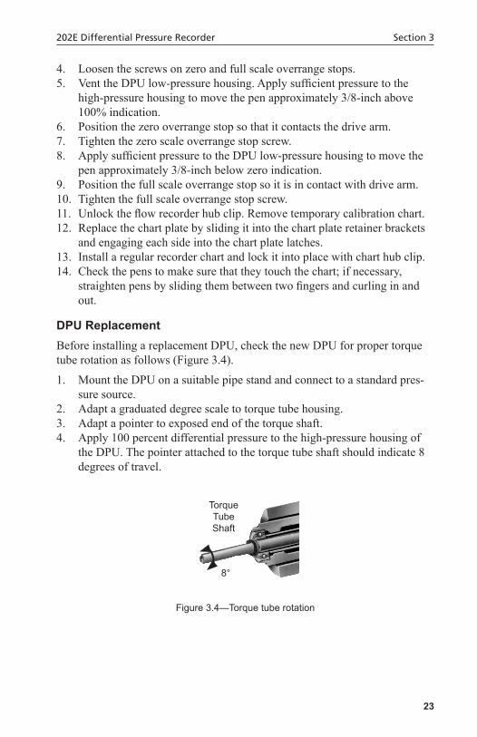
DPUReplacementBefore installing a replacement DPU, check the new DPU for proper torque tube rotation as follows (Figure 3.4).
1. Mount the DPU on a suitable pipe stand and connect to a standard pres-sure source.
2. Adapt a graduated degree scale to torque tube housing.3. Adapt a pointer to exposed end of the torque shaft.4. Apply 100 percent differential pressure to the high-pressure housing of
the DPU. The pointer attached to the torque tube shaft should indicate 8 degrees of travel.
8°
Torque Tube Shaft
Figure 3.4—Torque tube rotation

24
Section 3 202E Differential Pressure Recorder
DPUCleaningandInspection
! WARNING:TakenecessaryprecautionswhendisassemblingaDPUthathasbeenusedinahigh-pressuregasinstallations(withpressuresgreaterthan200psi).BeforeremovingtheDPUhousingbolts,performthepressurecheckprocedureonpage24.
IMPORTANT: If accumulation of solids or semi-solids is extensive, remove the hous-ings carefully to prevent damaging the bellows.
Pressure Check Procedure
! WARNING:Failuretoperformthisprocedurecanresultinsevereinjury,deathorsubstantialpropertydamageduetothereleaseofinternalpres-sure.
This procedure should be performed prior to removing the DPU housing bolts, if the DPU has been installed in gas applications with working pres-sures greater than 200 psig.
1. Back off all housing bolts 4 turns.2. Check for internal pressure by attempting to move the housing in and out
along the bolts. If the housing moves freely, no pressure is present and servicing or repair may continue.
! WARNING:Ifthehousingdoesnotmovefreely,thebellowsmaybepres-surizedandispotentiallyhazardousiffurtherdisassembled.TightentheboltsandreturntheunittothefactoryorauthorizedBartonservicecenterforrepair.Tagtheunitandspecify“GasinBellows.”
Cleaning/Inspection Procedure
Instruments used where solids or semi-solids may accumulate inside the pres-sure housings require periodic inspection and cleaning, as follows.
1. Remove the DPU from service and remove the pressure housings.2. Carefully remove the pressure housings from the bellows unit assembly.
CAUTION: Iftheaccumulationofmaterialinsidethehousingisextensive,rapidremovalofthehousingmaydamagethebellowsconvolu-tions.
25
202E Differential Pressure Recorder Section 3
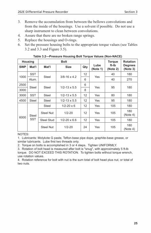
3. Remove the accumulation from between the bellows convolutions and from the inside of the housings. Use a solvent if possible. Do not use a sharp instrument to clean between convolutions.
4. Assure that there are no broken range springs.5. Replace the housings and O-rings.6. Set the pressure housing bolts to the appropriate torque values (see Tables
3.2 and 3.3 and Figure 3.5).
Table3.2—PressureHousingBoltTorqueValues(Non-NACE)Housing Bolt
Lube (Note 1)
Torque ft-lb
(Note 2)
Rotation Degrees (Note 3)SWP Mat'l Mat'l Size Qty
1000SST
Steel 3/8-16 x 4.212
Yes40 180
Alum. 6 40 270
2500Steel Steel 1/2-13 x 5.5
6Yes 95 180
3000 8
3000 SST Steel 1/2-13 x 5.5 12 Yes 80 180
4500 Steel Steel 1/2-13 x 5.5 12 Yes 95 180
6000 Steel SST
Steel 1/2-20 x 6 12 Yes 105 180
Steel Nut 1/2-20 12 Yes 105 180 (Note 4)
Steel Stud 1/2-20 x 6.6 12 Yes 105 180
Steel Nut 1/2-20 24 Yes 105 180 (Note 4)
NOTES:1. Lubricants: Molykote G paste, Teflon-base pipe dope, graphite-base grease, or similar lubricants. Lube first two threads only.2. Torque on bolts is accomplished in 3 or 4 steps. Tighten UNIFORMLY.3. Rotation of bolt head is measured after bolt is "snug", with approximately 5 ft-lb torque. DO NOT EXCEED THIS ROTATION. To tighten bolts without torque wrench, use rotation values.4. Rotation reference for bolt with nut is the sum total of bolt head plus nut, or total of two nuts.

26
Section 3 202E Differential Pressure Recorder
Table3.3—PressureHousingBoltTorqueValues(NACE)
ItemSWP
2000 PSI (13.8 MPa)
3000 PSI (20.7 MPa)
4500 PSI (31.0 MPa)
Fastener 12 Pt. Head Bolt 12 Pt. Head Bolt with Hex Nut
12 Pt. Head Bolt with Hex Nut
Bolt Size 1/2-13 x 5.5" 1/2-20 x 6" 1/2-20 x 6"
Bolt Material B7M/L7M Steel B7M/L7M Steel B7M/L7M Steel
Nut Size N/A 1/2-20 1/2-20
Nut Material N/A 4140 Steel 4140 Steel
Quantity 6 12 12
Torque (ft-lb) 55-60 55-60 55-60
NOTES:1. Lubricants: Molykote G paste, Teflon-base pipe dope, graphite-base grease, or simi-lar lubricants. Lube first two threads only. Do not lube bearing surface.2. Torque on bolts is accomplished in 3 or 4 steps. Tighten UNIFORMLY.3. If originally supplied with unit, re-install the "Do Not Reuse Bolts" and "NACE" prod-uct tags.
Figure 3.5—Rotation of head bolt and nuts when tightening

27
202E Differential Pressure Recorder Section 3
Change of DPU RangeChanging the range of the Model 199 DPU requires replacing the bellows unit assembly with a unit of the desired range (see Bellows Unit Assembly (BUA) Replacement on page 30).
! WARNING:TakenecessaryprecautionswhendisassemblingaDPUthathasbeenusedinahigh-pressuregasinstallations(withpressuresgreaterthan200psi).BeforeremovingtheDPUhousingbolts,performthepressurecheckprocedureonpage24.SeeCleaningandInspectiononpage24.
IMPORTANT: The calibration range of the DPU was carefully set at the factory. The following procedure maintains the original factory bellows travel setting while the range spring change is performed. This procedure must be strictly followed while changing the range spring assembly or altering the adjustment.
To replace the range spring assembly with either a new assembly of the same range or one with a different range value, perform one of the procedures be-low. These procedures assume that the DPU is either connected to an indicat-ing instrument or fitted with a scale and pointer to measure torque tube shaft movement.
2-1/8-in. Diameter Bellows1. Remove the DPU from service .2. Remove the pressure housing bolts and the low-pressure housing.3. With the pointer at zero, remove the spring retainer screw, retainer
springs, and the range spring assembly.
IMPORTANT: The pointer will shift from zero. This is a normal action and the pointer should not be readjusted at this point.
4. Install the new range spring assembly onto the push rod, and replace the spring retainer screw.
5. If the pointer is set above zero, rotate the spring adjustment clockwise until the pointer is set at zero. If the pointer is below zero rotate the spring adjustment conterclockwise until the pointer is set at zero.
6. Replace and tighten the lock nut. If the pointer shifts from zero, loosen the lock nut and reset the pointer as in step 5. Tighten the lock nut.
7. Replace the low-pressure housing and bolts (new gaskets are recom-mended). Use the torque values listed in Table 3.2 and Table 3.3.
8. Calibrate in accordance with the technical manual for the actuated instru-ment.

28
Section 3 202E Differential Pressure Recorder
3-3/4-in. Diameter Bellows Without Kickoff Spring (above 50-inches w.c.)1. Remove the instrument from service.2. Remove the pressure housing bolts and the low-pressure housing.3. With the pointer set at zero, remove the lock nut retainer nuts, and the
range spring assembly. To remove the range spring assembly, rotate the assembly counterclockwise while pulling outward on the assembly.
IMPORTANT: The pointer will shift from zero. This is a normal action and the pointer should not be readjusted at this point.
4. Thread the new assembly onto the push rod, and align the holes in the range spring assembly with the spring posts. Replace and tighten the retainer nuts.
5. Using a spanner wrench, rotate the spring adjustment until the pointer is set at exact zero. Replace and tighten the lock nut. The pointer must remain at the zero setting. If the pointer shifts from zero, loosen the lock nut and repeat this step.
6. Replace the low-pressure housing and bolts (new gaskets are recom-mended). Use the torque values listed in Table 3.2 and Table 3.3.
7. Calibrate in accordance with the technical manual for the actuated instru-ment.
3-3/4-Inch Diameter Bellows With Kickoff (“anti-stick”) Spring
IMPORTANT: The kickoff spring is supplied with the 0-40” w.c. and lower range DPUs as standard equipment. It is optional with 0-50” w.c. DPUs.
1. Remove the instrument from service. Set the pointer (or pen) at zero, using the instrument zero adjustment.
2. Remove the pressure housing bolts and remove the low-pressure housing. 3. With the pointer set at zero, remove the lock nut, four spring retainer
nuts, washer and lock nut, and range spring assembly.
IMPORTANT: The pointer will shift from zero. This is a normal action and the pointer should not be readjusted at this time.
4. Install the range spring assembly, using a 1/2-inch open-ended wrench to connect the push rod to the low-pressure bellows cup.
IMPORTANT: The range spring assembly consists of the range springs, kickoff spring assembly, and the push rod. The assembly is furnished as a complete and assembled unit.

29
202E Differential Pressure Recorder Section 3
Figure 3.6—Range spring assembly
5. Position the range spring assembly over the retainer posts and replace the retainer nuts.
6. Insert the tubing between the range springs and tighten the inboard lock nut.
7. Zero the pointer by adjusting the spud on the push rod. Be sure that the kickoff spring is not engaged during this operation.
8. Position the kickoff spring to prevent interference with the coil springs and tighten the kickoff spring lock nut. If clearance is needed for the wrench during this operation, note the position of the spud (measure with a scale or count threads to the end of the push rod) and move the spud for the required clearance. After the lock nut is tightened, return the spud to the original position.
IMPORTANT: The lock nut requires a special wrench for tightening. See illustration below for information on how to modify a 7/16-inch, 12 point box wrench.
Figure 3.7—Modified wrench for tightening lock nut
9. Check the back-clearance between the kickoff spring and the slot. Use a wire feeler gage or comparable measuring device. The clearance will vary between each individual slot but must be at least 0.005-inch for any one slot to prevent interference with instrument zero. Add or remove
30
Section 3 202E Differential Pressure Recorder
washers as required to obtain the proper clearance. Tighten the lock nut securely.
10. Install the jam nut and lock the spud to the push rod. Hold with pliers. If the spud was moved in step 9, return the spud to the proper position before tightening the jam nut.
11. Apply 100 percent negative pressure to the high-pressure side of the DPU and repeat the clearance check and adjustment of step 9.
12. Apply 100 percent positive pressure to the high-pressure side of the DPU and repeat the clearance check and adjustment of step 9.
13. Release all pressure from the instrument and replace the low-pressure housing. Use new gaskets.
14. Replace the housing bolts. Use the torque values listed in Table 3.2 and Table 3.3.
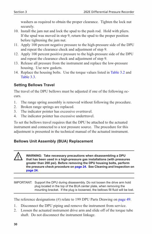
Setting Bellows TravelThe travel of the DPU bellows must be adjusted if one of the following oc-curs.
1. The range spring assembly is removed without following the procedure.2. Broken range springs are replaced.3. The indicator pointer has excessive overtravel.4. The indicator pointer has excessive undertravel.
To set the bellows travel requires that the DPU be attached to the actuated instrument and connected to a test pressure source. The procedure for this adjustment is presented in the technical manual of the actuated instrument.
BellowsUnitAssembly(BUA)Replacement
! WARNING:TakenecessaryprecautionswhendisassemblingaDPUthathasbeenusedinahigh-pressuregasinstallations(withpressuresgreaterthan200psi).BeforeremovingtheDPUhousingbolts,performthepressurecheckprocedureonpage24.SeeCleaningandInspectiononpage24.
IMPORTANT: Support the DPU during disassembly. Do not loosen the drive arm hold plug located in the top of the BUA center plate, when removing the mounting bracket. If the plug is loosened, the bellows fill fluid will be lost.
The reference designations (#) relate to 199 DPU Parts Drawing on page 49.
1. Disconnect the DPU piping and remove the instrument from service. 2. Loosen the actuated instrument drive arm and slide off of the torque tube
shaft. Do not disconnect the instrument linkage.

31
202E Differential Pressure Recorder Section 3
3. Remove the four case-retaining screws and remove the case assembly.4. Remove three mounting bracket screws and remove bracket (18). 5. Remove the pressure housings bolts and pressure housings (26). 6. Place the pressure housings (26) on the replacement bellows unit assem-
bly (1) and insert and start (only) the pressure housing bolts.7. Attach the case mounting bracket (18) to the replacement assembly, us-
ing three mounting bracket screws.8. Support the DPU and tighten and torque the pressure housing bolts to the
specifications listed in Table 3.2 and Table 3.3.9. Attach the case assembly using four case retaining screws.10. Attach linkage to DPU torque tube shaft.
a. Tighten clamp screw until “snug.”b. Tighten further, 1/3 to 1/2 turn of screw.c. Test by moving end of drive arm, approx. 1/2”.
4. Replace/adjust components removed or moved to gain access to DPU case mounting screws.
5. Calibrate the instrument before returning it to service.
Figure 3.8—Linkage attachment to DPU

32
Section 3 202E Differential Pressure Recorder

33
202E Differential Pressure Recorder Section 4
Section 4—Troubleshooting
Table 4.1 and Table 4.2, page 34, provide a description of problems, common causes, and recommended corrections. For further assistance, contact your local Cameron field representative.
Table 4.1—Troubleshooting GuideProblem Source Probable Cause Corrective Action
Low or No Indication
Mechanism Loose links or move-ments
Tighten or replace
Out of calibration Recalibrate
Corrosion or dirt in mechanism
Clean or replace
Pen arm loose Tighten
Pen arm Pen arm bent Straighten or replace pen arm
High Indication Mechanism Loose links or move-ments
Tighten or replace
Out of calibration Recalibrate
Erratic Indication Mounting Excessive vibration Secure the means of mounting
Mechanism Linkage dragging or dirty
Adjust or clean
Excessive pen pres-sure on chart
Adjust
No Chart Rotation Fuse Fuse blown Check and replace fuse
Chart Drive Electric drive not turned on
Turn on chart drive
Clock motor not wound
Wind chart drive
Defective drive Replace drive
Wrong Chart Speed
Chart Hub Lock Lock not latched Latch hub lock
Chart Drive Wrong chart drive Replace with proper chart drive
34
Section 4 202E Differential Pressure Recorder
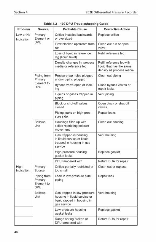
Table 4.2—199 DPU Troubleshooting GuideProblem Source Probable Cause Corrective Action
Low or No Indication
Primary Element or DPU
Orifice installed backwards or oversized
Replace orifice
Flow blocked upstream from run
Clean out run or open valve
Loss of liquid in reference leg (liquid level)
Refill reference leg
Density changes in process media or reference leg
Refill reference legwith liquid that has the same density as process media
Piping from Primary Element to DPU
Pressure tap holes plugged and/or piping plugged
Clean out piping
Bypass valve open or leak-ing
Close bypass valves or repair leaks
Liquids or gases trapped in piping
Vent piping
Block or shut-off valves closed
Open block or shut-off valves
Piping leaks on high-pres-sure side
Repair leaks
Bellows Unit
Housings filled up with solids restricting bellows movement
Clean out housing
Gas trapped in housing in liquid service or liquid trapped in housing in gas service
Vent housing
High-pressure housing gasket leaks
Replace gasket
DPU tampered with Return BUA for repair
High Indication
Primary Source
Orifice partially restricted or too small
Clean out or replace
Piping from Primary Element to DPU
Leak in low-pressure side piping
Repair leak
Bellows Unit
Gas trapped in low-pressure housing in liquid service or liquid rapped in housing in gas service
Vent housing
Low-pressure housing gasket leaks
Replace gasket
Range spring broken or DPU tampered with
Return BUA for repair

35
202E Differential Pressure Recorder Section 4
Table 4.2—199 DPU Troubleshooting GuideProblem Source Probable Cause Corrective Action
Erratic Indication
Primary Element
Flow pulsating Install dampening device upstream or DPU run
Piping from Primary Element to DPU
Liquid trapped in gas piping or gas bubble in liquid piping
Remove
Vapor generator incorrectly installed
Repipe
Reference leg gasy or liquid vaporizing
See piping instructions
Bellows Unit
Obstructed bellows travel Clean bellows
Gas trapped in DPU high-pressure or low-pressure housing
Remove (see startup procedures)

36
Section 4 202E Differential Pressure Recorder

37
202E Differential Pressure Recorder Section 5
Section 5—Installation/Dimensional Drawings
Model 202E (Part No. 9A-0202-101.3)

38
Section 5 202E Differential Pressure Recorder
Model 202E (cont'd)
39
202E Differential Pressure Recorder Section 5
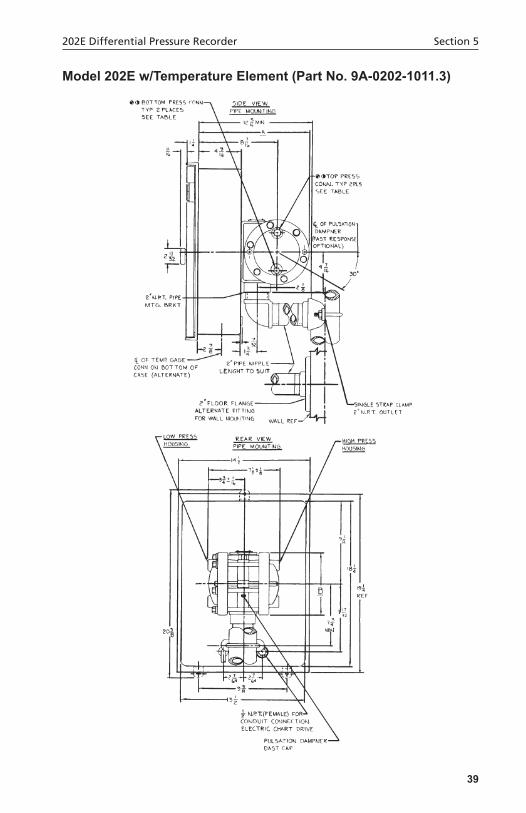
Model202Ew/TemperatureElement(PartNo.9A-0202-1011.3)

40
Section 5 202E Differential Pressure Recorder
Model202Ew/TemperatureElement(cont'd)

41
202E Differential Pressure Recorder Section 5
Model 199 DPU (Part No. 9A-0199.0903.3)

42
Section 5 202E Differential Pressure Recorder
Model 199 DPU (cont'd)

43
202E Differential Pressure Recorder Section 6
Section 6—Assembly Drawings and Parts Lists
202E Recorder
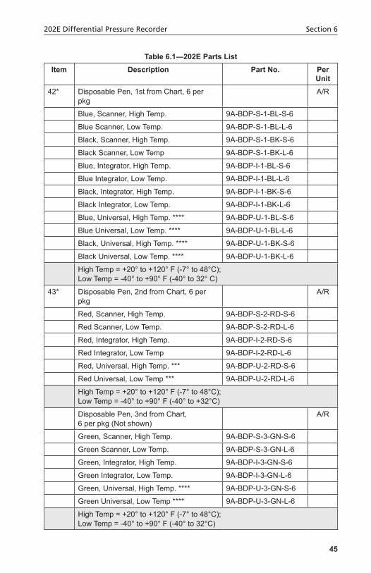
Table 6.1—202E Parts ListItem Description Part No. Per
Unit1 Door Assembly, Flow Recorder 9A-0238.1023.B 1
2 Case, Flow Recorder 9A-0238.1186.C 1
3 Assembly, Pen Lifter 9A-0238.1159.B 1
4 Riser, Chart Drive 9A-0238.0007.C 3
5 Door Latch 9A-0238.0071.C 1
6 Overrange Stop 9A-0238.0082.C 2
7 Riser, Chart Plate 9A-0238.1210.C 4
8 Screw, Fil. Hd. (Chart Plate) 9A-0114.1036.J 4
9 Bushing, Door Stop 9A-0238.1018.C 1
10 Screw, Cap 1/4-20 x 5/8 (Riser) 9A-S797.0048.Z 4
11 Hinge, Door 9A-0238.1034.C 1
44
Section 6 202E Differential Pressure Recorder
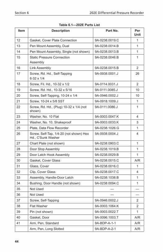
Table 6.1—202E Parts ListItem Description Part No. Per
Unit12 Gasket, Cover Plate Connection 9A-0238.0019.C 1
13 Pen Mount Assembly, Dual 9A-0238.0014.B 1
14 Pen Mount Assembly, Single (not shown) 9A-0238.0013.B 1
15 Static Pressure Connection Assembly
9A-0238.0046.B 1
16 Link Assembly 9A-0238.0015.B 2
17 Screw, Rd. Hd., Self-Tapping 6-32 x 1/4
9A-0938.0001.J 26
18 Screw, Fil. Hd., 10-32 x 1/2 9A-0114.0031.J 2
19 Screw, Rd. Hd., 10-32 x 5/16 9A-0111.0085.J 10
20 Screw, Self-Tapping, 10-24 x 1/4 9A-0946.0002.J 10
21 Screw, 10-24 x 5/8 SST 9A-0918.1009.J 1
22 Screw, Rd. Hd., (Plug) 10-32 x 1/4 (not shown)
9A-0111.0086.J 1
23 Washer, No. 10 Flat 9A-0003.0047.K 4
24 Washer, No. 10, Shakeproof 9A-0003.0033.K 3
25 Plate, Data Flow Recorder 9A-0238.1026.G 1
26 Screw, Self-Tap, 1/4-20 (not shown) Hex Hd., C'Sunk Washer
9A-0938.0004.J 4
27 Chart Plate (not shown) 9A-0238.0903.C 1
28 Door Stop Assembly 9A-0238.1019.B 1
29 Door Latch Hook Assembly 9A-0238.0029.B 1
30 Gasket, Cover Glass 9A-0238.0015.C A/R
31 Glass, Cover 9A-0238.0016.C 1
32 Clip, Cover Glass 9A-0238.0017.C 4
33 Assembly, Handle-Door Latch 9A-0238.1038.B 1
34 Bushing, Door Handle (not shown) 9A-0238.0094.C 1
35 Not Used — —
36 Not Used — —
37 Screw, Self-Tapping 9A-0946.0002.J 2
38 Flat Washer 9A-0003.1064.K 2
39 Pin (not shown) 9A-0003.0022.T 1
40 Gasket, Door 9A-0096.1003.T A/R
41 Arm, Pen, Standard 9A-BDP-A-1-1 A/R
Arm, Pen, Long Slotted 9A-BDP-A-2-1 A/R
45
202E Differential Pressure Recorder Section 6
Table 6.1—202E Parts ListItem Description Part No. Per
Unit42* Disposable Pen, 1st from Chart, 6 per
pkgA/R
Blue, Scanner, High Temp. 9A-BDP-S-1-BL-S-6
Blue Scanner, Low Temp. 9A-BDP-S-1-BL-L-6
Black, Scanner, High Temp. 9A-BDP-S-1-BK-S-6
Black Scanner, Low Temp 9A-BDP-S-1-BK-L-6
Blue, Integrator, High Temp. 9A-BDP-I-1-BL-S-6
Blue Integrator, Low Temp. 9A-BDP-I-1-BL-L-6
Black, Integrator, High Temp. 9A-BDP-I-1-BK-S-6
Black Integrator, Low Temp. 9A-BDP-I-1-BK-L-6
Blue, Universal, High Temp. **** 9A-BDP-U-1-BL-S-6
Blue Universal, Low Temp. **** 9A-BDP-U-1-BL-L-6
Black, Universal, High Temp. **** 9A-BDP-U-1-BK-S-6
Black Universal, Low Temp. **** 9A-BDP-U-1-BK-L-6
High Temp = +20° to +120° F (-7° to 48°C);Low Temp = -40° to +90° F (-40° to 32° C)
43* Disposable Pen, 2nd from Chart, 6 perpkg
A/R
Red, Scanner, High Temp. 9A-BDP-S-2-RD-S-6
Red Scanner, Low Temp. 9A-BDP-S-2-RD-L-6
Red, Integrator, High Temp. 9A-BDP-I-2-RD-S-6
Red Integrator, Low Temp 9A-BDP-I-2-RD-L-6
Red, Universal, High Temp. *** 9A-BDP-U-2-RD-S-6
Red Universal, Low Temp *** 9A-BDP-U-2-RD-L-6
High Temp = +20° to +120° F (-7° to 48°C);Low Temp = -40° to +90° F (-40° to +32°C)
Disposable Pen, 3nd from Chart, 6 per pkg (Not shown)
A/R
Green, Scanner, High Temp. 9A-BDP-S-3-GN-S-6
Green Scanner, Low Temp. 9A-BDP-S-3-GN-L-6
Green, Integrator, High Temp. 9A-BDP-I-3-GN-S-6
Green Integrator, Low Temp. 9A-BDP-I-3-GN-L-6
Green, Universal, High Temp. **** 9A-BDP-U-3-GN-S-6
Green Universal, Low Temp **** 9A-BDP-U-3-GN-L-6
High Temp = +20° to +120° F (-7° to 48°C);Low Temp = -40° to +90° F (-40° to 32°C)

46
Section 6 202E Differential Pressure Recorder
Table 6.1—202E Parts ListItem Description Part No. Per
UnitDisposable Pen, 3nd from Chart,6 per pkg (Not shown)
A/R
Purple, Universal, High Temp. **** 9A-BDP-U-4-PL-S-6
Purple Universal, Low Temp. **** 9A-BDP-U-4-PL-L-6
High Temp = +20° to +120° F (-7° to 48°C);Low Temp = -40° to +90° F (-40° to +32°C)
44 Static Shaft Arm Assembly 9A-0202.0034.B 1
45 Range Arm Assembly 9A-0238.0012.B 1
46 Block, Clamp 9A-0250.0003.C 1
47 Lever Arm Assembly 9A-0238.0031.B 1
48 Drive Arm Assembly 9A-0238.0004.B 1
49 Element, Static Pressure See Table 6.2
50 Drive Chart See Table 6.3
51 Shaft, Pen Arm (1st from Chart) 9A-0238.0006.B 1
52 Shaft, Pen Arm (2nd from Chart) 9A-0238.0007.B 1
53 Hub, Chart 9A-0238.0033.B 1
55 Screw, Sl. Hex Hd., 8-32 x 1/4 (Pen Mount, Top Plate)
9A-0116.0014.J 2
56 Washer, Lock #8 (Pen Mount, Top Plate)
9A-0003.0036.K 2
57 Screw, Sl. Fil. Hd., 6-40 x 1/4 (Chart Drive)
9A-0114.0017.J 3
58 Screw, Set, 2-56 x 5/32 (Drive Arm) 9A-0200.0040.C 3
59 Differential Pressure Unit (not shown)
Specify 1
60 Counterweight 9A-0238.1165.C 1
61 Screw, Counterweight Clamp 9A-0238.1201.C 1

47
202E Differential Pressure Recorder Section 6
Table 6.2—Static Pressure ElementsPart No. Alt. Part No. StandardRange(psi)a
HelicalElements(316SST;1/8”UnionConnection;RangesinPSIG)9A-B17SL-25 0-25
9A-B17SL-35 0-35
9A-B17SL-50 9A0044-0040T 0-50
9A-B17SL-75 0-75
9A-B17SL-100 9A-0044-0035T 0-100
9A-B17SL-150 9A-0044-0099T 0-150
9A-B17SL-200 0-200
9A-B17SL-250 9A-0044-0036T 0-250
9A-B17SL-300 9A-0044-0044T 0-300
9A-B17SL-350 0-350
9A-B17SL-400 0-400
9A-B17SL-500 9A-0044-0041T 0-500
9A-B17SL-600 0-600
9A-B17SL-750 9A-0044-0100T 0-750
9A-B17SL-1000 9A-0044-0042T 0-1000
9A-B17SL-1500 9A-0044-0046T 0-1500
9A-B17SL-2000 0-2000
9A-B17SL-2500 9A-0044-0048T 0-2500
9A-B17SL-3000 0-3000
9A-B17SL-3500 9A-0044-0050T 0-3500
9A-B17SL-4000 0-4000
9A-B17SL-5000 9A-0044-0054T 0-5000
9A-B17SL-6000 0-6000
Part No. StandardRange(psi)a
Capsular9A-BCR3-15SL SST: Range (PSI): 3-15
Monel9A-B17MK-XXXX“XXXX” = Range in PSIG
Available in ranges from 0-250 PSIG thru 0-6000 PSIG (W/18” Welded Connection Line) ¼” FNPT Conn.
a Unit can be adjusted to include vacuum measurement.

48
Section 6 202E Differential Pressure Recorder
Table 6.3—Chart DrivesPart No. Description Model No.
Mechanical(SpringWound)9A-0042-0015T 24 Hour/9 Day 725R060
9A-0042-0016T 7 Day 725R061
9A-0042-0017T 24 Hour/7 Day 725R084
9A-0042-0030 8 Day 725R067
9A-0042-0031T 24 Hour/8 Day 725R068
9A-0042-1004T 31 Day 725R070
9A-0042-1003T 2 Hour/8 Hour 725R077
9A-0042-0024T 4 Hour 725R081
9A-0042-1007T 1 Hour/15 Minute 725R086
9A-0042-0020T 96 Minute/24 Hour 725R175
9A-0042-1009T 1 Hour/3 Hour 725R138
BatteryDriven(1.5VDC-CCellAlkaline)9A-0043-1002T 11 Selectable Speeds 820R001
9A-0043-1003T 11 Selectable Speeds (Foxboro)
820R007
9A-0043-1004T 11 Selectable Speeds (CSA Approved)
820R011
9A-0043-1005T 12 Selectable Speeds(Including 4 Hour)
820R029
9A-0043-2001T Fast Slow Speeds 830R001
Chart Drive Accessories9A-0238-0033B One Piece Hub 725G190
Hub (Used w/ 625G070) 725G198
Cap & Chain (Used w/ 725G198)
625R070
Universal Mounting Plate 620G164
Wind Key 725G364
Wind Key, Long Shank 725G357
Push/Pull Hub (Foxboro) 725R004

49
202E Differential Pressure Recorder Section 6
199 DPU Assembly

50
Section 6 202E Differential Pressure Recorder
! WARNING:InNACE-qualifiedservice,useonlyNACE-qualifiedreplace-mentpartsforhousings,bolts,andBUA.ForNACEboltpartnumbers,refertoTable6.5.AnydeviationfromuseofqualifiedNACEpartsinNACE service will void the instrument/DPU NACE rating(s).
Table 6.4—199 DPU Assembly Parts ListItem Description Part No. Per
Unit1 Bellows Unit Assembly (BUA) (Specify) 1
2* Post, Calibration Spring Retainer (for 3-3/4" Bellows)
9A-0199-0019C 4
3 Rod, Spring Push 9A-0199-0049C 1
4* Screw, Retainer, 6-32 x 5/16" 9A-0111-0049J 8
5* Spring Assembly, Calibration Tension (for 2-1/8" Bellows)
(Specify) 1
6 Nut, Lock, Spring Adjust 9A-0199-0144C 1
7 Plug, Pipe, 1/4" NPT, Steel 9A-0199-0191C 2
8 Plug, Pipe, 1/2" NPT, Steel 9A-0199-0192C 2
9 Bolt, Housing (Standard Units):** A/R
Stainless Steel, 1000 PSI Units 9A-0199-1345C
Steel, 2500/3000/4500 PSI Units 9A-0199-0085C
Stud, Alloy Steel, 1/2-20 x 7 for 6000 PSI Units (Not Shown
9A-0199-1001C
Bolt for 6000 PSI Units (Not Shown 9A-0199-1346C
10* Screw, Pipe Mount Adapter, 3/8-16 x 3/4" 9A-0210-0012J 1
11 Screw, Sch Cap, Steel, 3/8-16 x 1-1/2" Lg. 9A-0220-1102J 2
12* Screw, 3/8-16 x 5/8", Steel (for Item 13) 9A-0310-0013J 3
13 Adapter, Pipe Mounting 9A-0199-0988C 1
14* Nut, Spring Retainer, Hex, 6-32, SM Pattern, SST (for 3-3/4" Bellows)
9A-0500-0028J 8
15* Assembly, Range Spring (for 3-3/4" Bellows) (Specifiy) 1
16 Spacer, Indicator Bracket 9A-0199-0006C 2
17 Screw, Indicator Bracket (Soc. Flat, 3/8-16 x 7/8", ST)
9A-0240-0003J 1
18 Bracket (Specify) 1
19 Screw, Indicator Bracket, Hex, Washer Hd., 3/8 x 1-1/8"
9A-0002-1009T 2
20 Screw, Recorder Bracket, Hex, Washer hd., 3/8-16 x 1/2"
9A-0002-0034T 1
21* O-Ring, 2-127, Nitrile N3** 9A-0001-1178R 1

51
202E Differential Pressure Recorder Section 6
Table 6.4—199 DPU Assembly Parts ListItem Description Part No. Per
Unit22* Gasket, Torque Tube 9A-0199-0209C 1
23 Not Used
24 Screw, Recorder Bracket, Hex, Washer Hd., 3/8-16 x 5/8"
9A-0002-0033T 2
25* Gasket, Pressure Housing:** 2
1000 PSI Aluminum Units 9A-0199-0027C
2500/3000/4500 PSI Steel Units 9A-0199-0027C
1000/3000/6000 PSI SST & Monel Units 9A-0199-0184C
26 Housing, Pressure (Specify) 2
27 Washer, Lock, 3/8" (Used with Items 10 & 11) 9A-0275-0049C 1
29 Nut, 1/2-20, 6000/3000 PSI Monel Units (Used with Item 9)**
9A-0199-1002C A/R
30* Plug, Dampener Valve (Not Shown) Bd Hd., 1/4-28 x 1/4", SST
9A-0199-0036C 1
32* Wrench, Range Spring Adjustment 9A-0199-0142C 1
33 Keys, Set of Hex (Not Shown) 9A-0016-0013T 1
* Recommended spare part.** For NACE parts, refer to Table 6.5.A/R - As required.When ordering parts, specify instrument serial number.
Table6.5—NACEReplacementPartsItem Description Part No. Per Unit
1 Bolt, Housing, Standard Units, B7M/L7M Steel, 2000 PSI, NACE
9A-0220-1075J A/R
2 Bolt, Housing, Standard Units, B7M/L7M Steel, 3000/4500 PSI, NACE
9A-S408-0064Z A/R
3 Nut, 1/2-20, 4140 Steel, 3000/4500 PSI, NACE
9A-S408-0021Z A/R
4 Gasket, Housing, 2000 PSI, NACE 9A-S0001-1140R A/R
5 Gasket, Housing, 3000/4500 PSI, NACE 9A-S528-0001Z A/R
6 O-Ring, Housing, 2-127, Nitrile N3, NACE 9A-0001-1099R A/R

52
Section 6 202E Differential Pressure Recorder
InstrumentSpecificationsCase ............................................... Die-cast aluminum, black epoxy resin paint, water-
proof and weather resistant; hinged door; neoprene gasket seal
DP Accuracy:0-20” w.c. to 0-349” w.c. ................. ±0.5% of full scale0-350” w.c. to 0-75 psi .................... ±0.75% of full scaleSP Accuracy ................................... ±1.0% of full scale
53
202E Differential Pressure Recorder Section 6
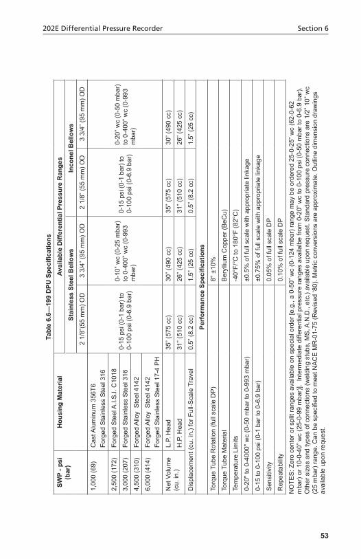
Table6.6—
199DPU
Specifications
SWP-p
si(b
ar)
Hou
sing
Material
Avai
labl
e D
iffer
entia
l Pre
ssur
e R
ange
sSt
ainl
ess
Stee
l Bel
low
sIn
cone
l Bel
low
s2
1/8”
(55
mm
) OD
3 3/
4” (9
5 m
m) O
D2
1/8”
(55
mm
) OD
3 3/
4” (9
5 m
m) O
D
1,00
0 (6
9)C
ast A
lum
inum
356
T6Fo
rged
Sta
inle
ss S
teel
316
0-15
psi
(0-1
bar
) to
0-10
0 ps
i (0-
6.9
bar)
0-10
” wc
(0-2
5 m
bar)
to
0-4
00” w
c (0
-993
m
bar)
0-15
psi
(0-1
bar
) to
0-10
0 ps
i (0-
6.9
bar)
0-20
” wc
(0-5
0 m
bar)
to
0-4
00” w
c (0
-993
m
bar)
2,50
0 (1
72)
Forg
ed S
teel
A.I.
S.I.
C10
18
3,00
0 (2
07)
Forg
ed S
tain
less
Ste
el 3
16
4,50
0 (3
10)
Forg
ed A
lloy
Ste
el 4
142
6,00
0 (4
14)
Forg
ed A
lloy
Ste
el 4
142
Forg
ed S
tain
less
Ste
el 1
7-4
PH
Net
Vol
ume
(cu.
in.)
L.P.
Hea
d35
” (57
5 cc
)30
” (49
0 cc
)35
” (57
5 cc
)30
” (49
0 cc
)
H.P
. Hea
d31
” (51
0 cc
)26
” (42
5 cc
)31
” (51
0 cc
)26
” (42
5 cc
)
Dis
plac
emen
t (cu
. in.
) for
Ful
l-Sca
le T
rave
l0.
5” (8
.2 c
c)1.
5” (2
5 cc
)0.
5” (8
.2 c
c)1.
5” (2
5 cc
)
PerformanceSpecifications
Torq
ue T
ube
Rot
atio
n (fu
ll sc
ale
DP
)8°
±10
%
Torq
ue T
ube
Mat
eria
lB
eryl
lium
Cop
per (
BeC
u)
Tem
pera
ture
Lim
its-4
0°F/
°C to
180
°F (8
2°C
)
0-20
" to
0-40
00" w
c (0
-50
mba
r to
0-99
3 m
bar)
±0.5
% o
f ful
l sca
le w
ith a
ppro
pria
te li
nkag
e
0-15
to 0
-100
psi
(0-1
bar
to 0
-6.9
bar
)±0
.75%
of f
ull s
cale
with
app
ropr
iate
link
age
Sen
sitiv
ity0.
05%
of f
ull s
cale
DP
Rep
eata
bilit
y0.
10%
of f
ull s
cale
DP
NO
TES
: Zer
o ce
nter
or s
plit
rang
es a
vaila
ble
on s
peci
al o
rder
[e.g
., a
0-50
” wc
(0-1
24 m
bar)
rang
e m
ay b
e or
dere
d 25
-0-2
5” w
c (6
2-0-
62
mba
r) o
r 10-
0-40
” wc
(25-
0-99
mba
r)].
Inte
rmed
iate
diff
eren
tial p
ress
ure
rang
es a
vaila
lbe
from
0-2
0” w
c to
0-1
00 p
si (0
-50
mba
r to
0-6.
9 ba
r).
Oth
er s
izes
and
type
s of
con
nect
ions
(wel
ding
stu
bs, M
S, A
.N.D
., et
c.) a
vaila
ble
upon
requ
est.
Sta
ndar
d pr
essu
re c
onne
ctio
ns a
re 1
/2” 1
0” w
c (2
5 m
bar)
rang
e. C
an b
e sp
ecifi
ed to
mee
t NA
CE
MR
-01-
75 (R
evis
ed ‘8
0). M
etric
con
vers
ions
are
app
roxi
mat
e. O
utlin
e di
men
sion
dra
win
gs
avai
labl
e up
on re
ques
t.

54
Section 6 202E Differential Pressure Recorder
5555
Product Warranty
A. WarrantyCameron International Corporation ("Cameron") warrants that at the time of shipment, the products manufactured by Cameron and sold hereunder will be free from defects in mate-rial and workmanship, and will conform to the specifications furnished by or approved by Cameron.
B. Warranty Adjustment1. If any defect within this warranty appears, Buyer shall notify Cameron immediately2. Cameron agrees to repair or furnish a replacement for, but not install, any product
which within one (1) year from the date of shipment by Cameron shall, upon test and examination by Cameron, prove defective within the above warranty.
3. No product will be accepted for return or replacement without the written authoriza-tion of Cameron. Upon such authorization, and in accordance with instructions by Cameron, the product will be returned shipping charges prepaid by Buyer. Replace-ments made under this warranty will be shipped prepaid.
C. Exclusions from Warranty1. THE FOREGOING WARRANTY IS IN LIEU OF AND EXCLUDES ALL OTHER
EXPRESSED OR IMPLIED WARRANTIES OF MERCHANTABILITY, OR FIT-NESS FOR A PARTICULAR PURPOSE, OR OTHERWISE.
2. Components manufactured by any supplier other than Cameron shall bear only the warranty made by the manufacturer of that product, and Cameron assumes no respon-sibility for the performance or reliability of the unit as a whole.
3. "In no event shall Cameron be liable for indirect, incidental, or consequential dam-ages nor shall the liability of Cameron arising in connection with any products sold hereunder (whether such liability arises from a claim based on contract, warranty, tort, or otherwise) exceed the actual amount paid by Buyer to Cameron for the products delivered hereunder."
4. The warranty does not extend to any product manufactured by Cameron which has been subjected to misuse, neglect, accident, improper installation or to use in violation of instructions furnished by Cameron.
5. The warranty does not extend to or apply to any unit which has been repaired or al-tered at any place other than at Cameron's factory or service locations by persons not expressly approved by Cameron.
Product Brand
Barton® is a registered trademark of Cameron International Corporation ("Cameron").

Top Related