


Languages
Pages
Legal


www.loytec.com124
Acce
ssor
ies
Inte
rfac
esRo
uter
s, N
ICL‑
DA
LIL‑
VIS,
L‑S
TAT
Gat
eway
sL‑
IOB
L‑IN
XL‑
ROC
L‑W
EB, L
‑STU
DIO
Func
tions
L‑D
ALI
LDALI‑ME201‑U, LDALI‑ME204‑UBACnet/ DALI Controller
L‑DALI Controllers are multifunctional devices combining constant light con‑trol, sunblind control and gateway functions between DALI (Digital Addressable Lighting Interface) and BACnet or Modbus systems. With Alarming, Scheduling, Trending and e‑mail notification (AST™) the L‑DALI Controller is a perfect solu‑tion for DALI lighting systems and for a smooth DALI integration into BACnet or Modbus networks.
DALI Network Interface
L‑DALI Controllers act as a DALI‑Master in the DALI network and can interact with DALI‑2 multi‑sensors and buttons in Multi‑Master mode. The LDALI‑ME204‑U device is equipped with 4 independent DALI channels. The LDALI‑ME201‑U device is equipped with 1 DALI channel. Up to 64 DALI or DALI‑2 based luminaries per DALI channel can be controlled individually or via 16 groups. All luminaries are monitored for lamp or ballast defect. In addition up to 64 DALI‑2 input devices are supported per DALI channel. Each input device can be equipped with push but‑tons, sliders, occupancy and light sensors.
Built-In DALI Bus Power Supply
All L‑DALI models come with a built‑in DALI bus power supply. The LDALI‑ME201‑U can supply its DALI channel with a guaranteed supply current of 230 mA, the LDALI‑ME204‑U can supply 116 mA per channel. In case of the LDALI‑ME204‑U an external DALI bus power supply can be added to top up the supply current to 232 mA. External power supplies are available for up to four DALI channels. The internal DALI bus power can be switched on and off via web interface or LCD UI. Thanks to the switching power supply, these devices can handle input voltages from 85 – 240 V AC, 50 / 60 Hz.
BACnet Connectivity
The L‑DALI Controllers feature connectivity in BACnet networks via BACnet/ IP or BACnet MS/ TP. They also provide data exchange through Global Connections and support comprehensive AST™ functionality (Alarming, Scheduling, and Trending). Full L‑WEB integration is supported as well. The L‑DALI Controllers are equipped with two Ethernet ports including a built‑in Ethernet switch.
IoT Integration
The IoT function (Node.js) allows connecting the system to almost any cloud ser‑vice, either for uploading historical data to analytics services, delivering alarm messages to alarm processing services or operating parts of the control system over a cloud service (e.g., scheduling based on Web calendars or booking sys‑tems). Processing Internet information such as weather data in forecast‑based control is also possible. Finally, the JavaScript kernel also allows implementing serial protocols to non‑standard equipment.
Local Operation and Override
The L‑DALI Controllers come with a built‑in backlit display (128x64) and a jog dial for local operation and override. Using the local operation, maintenance tasks (DALI device replacement, burn‑in mode, etc.) can be executed without the need of any software tool.
Constant Light Control
The integrated Constant Light Controller works with DALI and with BACnet devices. It supports various lighting control strategies, presence and lux level based. Several parameters can be used to configure the Constant Light Controller for almost any use case.
Sunblind Control with Constant Light Control Interaction
The integrated Sunblind Controller application allows intelligent controlling of blinds connected via SMI (requires LSMI‑804). It offers effective sun and anti‑glare
BACnet DALI CEA‑709 OPC Modbus
Datasheet #89021220
BACnetOPC
XML-DA
Gateway
serial
15 16 174 5 6 ~~+- DC
AC
statuspower
12-35 VDC INPUT or12-24 VAC, 40-70 Hz
ACTLINK
ACT
100Base-T100Base-T
Made in Austria
LOYTECwww.loytec.com
1
1 2 3
2
+ -RS-485RS-485
ABFT
RNI
PLC CNIP
LINX-110
Automation ServerL-INX
VNC
y=f(x)
SMIOPC UA enocean®
Modbus
VPN
WLAN
IoT SMS
LTE
DALI-2
buildings under controlwww.loytec.com 125
FunctionsL‑W
EB, L‑STUDIOL‑RO
CL‑IN
XL‑IO
BG
ateways
L‑VIS, L‑STATL‑D
ALI
Routers, NIC
InterfacesAccessories
L‑DA
LI
LDALI‑ME201‑U, LDALI‑ME204‑UBACnet/ DALI Controller
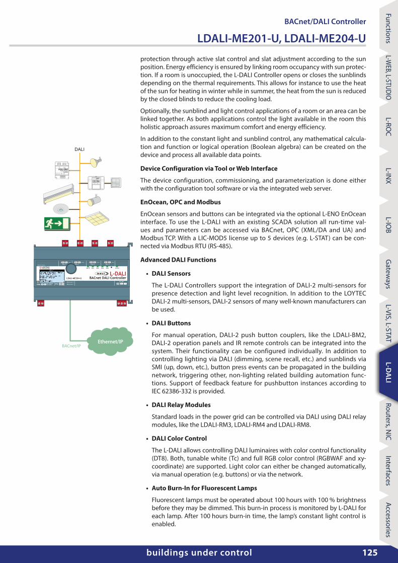
protection through active slat control and slat adjustment according to the sun position. Energy efficiency is ensured by linking room occupancy with sun protec‑tion. If a room is unoccupied, the L‑DALI Controller opens or closes the sunblinds depending on the thermal requirements. This allows for instance to use the heat of the sun for heating in winter while in summer, the heat from the sun is reduced by the closed blinds to reduce the cooling load.
Optionally, the sunblind and light control applications of a room or an area can be linked together. As both applications control the light available in the room this holistic approach assures maximum comfort and energy efficiency.
In addition to the constant light and sunblind control, any mathematical calcula‑tion and function or logical operation (Boolean algebra) can be created on the device and process all available data points.
Device Configuration via Tool or Web Interface
The device configuration, commissioning, and parameterization is done either with the configuration tool software or via the integrated web server.
EnOcean, OPC and Modbus
EnOcean sensors and buttons can be integrated via the optional L‑ENO EnOcean interface. To use the L‑DALI with an existing SCADA solution all run‑time val‑ues and parameters can be accessed via BACnet, OPC (XML/DA and UA) and Modbus TCP. With a LIC‑MOD5 license up to 5 devices (e.g. L‑STAT) can be con‑nected via Modbus RTU (RS‑485).
Advanced DALI Functions
• DALI Sensors
The L‑DALI Controllers support the integration of DALI‑2 multi‑sensors for presence detection and light level recognition. In addition to the LOYTEC DALI‑2 multi‑sensors, DALI‑2 sensors of many well‑known manufacturers can be used.
• DALI Buttons
For manual operation, DALI‑2 push button couplers, like the LDALI‑BM2, DALI‑2 operation panels and IR remote controls can be integrated into the system. Their functionality can be configured individually. In addition to controlling lighting via DALI (dimming, scene recall, etc.) and sunblinds via SMI (up, down, etc.), button press events can be propagated in the building network, triggering other, non‑lighting related building automation func‑tions. Support of feedback feature for pushbutton instances according to IEC 62386‑332 is provided.
• DALI Relay Modules
Standard loads in the power grid can be controlled via DALI using DALI relay modules, like the LDALI‑RM3, LDALI‑RM4 and LDALI‑RM8.
• DALI Color Control
The L‑DALI allows controlling DALI luminaires with color control functionality (DT8). Both, tunable white (Tc) and full RGB color control (RGBWAF and xy‑coordinate) are supported. Light color can either be changed automatically, via manual operation (e.g. buttons) or via the network.
• Auto Burn-In for Fluorescent Lamps
Fluorescent lamps must be operated about 100 hours with 100 % brightness before they may be dimmed. This burn‑in process is monitored by L‑DALI for each lamp. After 100 hours burn‑in time, the lamp’s constant light control is enabled.
Ethernet/IP
DALI
L-DALILOYTECwww.loytec.com
Made in Austria
Ethernet 2
PWR85-240VAC Ethernet 1LN
status
50/60Hz USB 1USB 2
BACnet DALI ControllerLDALI-ME204-U
DA1 DA2
DA-DA+DALI 4
DA+ DA-DALI 3
116mA 116mA
MSTP DA3 DA4
DA-DA+DALI 2
DA+ DA-DALI 1
RS-485
116mA 116mA
GND -+
BACnet/IP

www.loytec.com126
Acce
ssor
ies
Inte
rfac
esRo
uter
s, N
ICL‑
DA
LIL‑
VIS,
L‑S
TAT
Gat
eway
sL‑
IOB
L‑IN
XL‑
ROC
L‑W
EB, L
‑STU
DIO
Func
tions
L‑D
ALI
LDALI‑ME201‑U, LDALI‑ME204‑UBACnet/ DALI Controller
• DALI integration into BACnet networks
• Supports up to 64 DALI ballasts and 16 DALI groups per DALI channel
• Supports up to 64 input devices overall per channel
• Up to 16 DALI sensors per DALI channel are supported
• Up to 64 DALI button modules per DALI channel are supported
• Integrated DALI bus power supply
• Manual operation using the jog dial and local access to information about device status and data points in clear text and symbols
• 128x64 graphic display with backlight
• Built‑in web server for device configuration
• Test and assignment of DALI devices on the web interface
• Replacement of DALI devices without additional software tools via LCD and jog dial
• Supports the control of standard loads in the power grid via LDALI‑RM3, LDALI‑RM4 or LDALI‑RM8 Relay Modules
• Integrated Constant Light Controller
• Integrated Sunblind Controller
• Supports DALI‑2 devices (drivers and input devices)
• DALI‑2 certified (compliant with IEC 62386‑101 and IEC 62386‑103)
• Support DALI color control (DT8 tunable white & full color control)
• Supports lamp burn‑in mode
• Supports periodic testing of DALI emergency lights
• Integrated DALI Protocol Analyzer
• Compliant with ANSI/ ASHRAE 135‑2012 and ISO 16484‑5:2012 standard
• Supports BACnet/ IP or BACnet MS/ TP
Features
• Automatic Test of Emergency Lighting Systems
In DALI emergency lighting systems based on IEC 62386‑202, L‑DALI can be used for test‑ing the system. The results can be logged.
• Collection of Important Operational Parameters
For maximum transparency in the lighting system, L‑DALI can record the operating hours of each lamp and also the energy consumption (calculated).
• DALI Device Replacement made easy
Defective DALI ballasts can easily be replaced directly on the L‑DALI Controller (LCD and jog dial) or via the web interface. No software tool is necessary.
Smooth DALI Integration into BACnet and Modbus Networks
The L‑DALI Controller maps information from the DALI network to BACnet objects or Modbus registers that are used to control DALI ballasts or to display operating states.
BACnet Interface
The following BACnet server objects are supported:
• Analog Output objects to control DALI ballasts, groups, and channels
• Multi‑State Output objects for scene control of DALI groups and channels
• Analog Input objects providing feedback from DALI ballast, groups, and channels
• Analog Input objects providing status information from DALI groups and channels
• Accumulator objects providing estimated energy usage of DALI groups and channels
• Multi‑State Output objects to issue commands (start/stop emergency test or burn‑in, change color temperature, etc.) to DALI ballasts, groups and channels
• Analog Input objects providing battery status of emergency ballasts, groups
• Analog Input objects providing lux level information from supported DALI sensors (LDALI‑MS2: additionally humidity and temperature information is provided)
• Binary Input objects providing occupancy information from supported DALI sensors
• Loop objects providing constant light controller functionality
• Binary Input objects providing button information from supported DALI buttons
• Various objects to control sunblinds
All data points are available on the web server in a tree structure and can be displayed and set via a web browser.

buildings under controlwww.loytec.com 127
FunctionsL‑W
EB, L‑STUDIOL‑RO
CL‑IN
XL‑IO
BG
ateways
L‑VIS, L‑STATL‑D
ALI
Routers, NIC
InterfacesAccessories
L‑DA
LI
BACnet/ DALI Controller
LDALI‑ME201‑U, LDALI‑ME204‑U
SpecificationsType LDALI-ME201-U LDALI-ME204-U
Dimensions (mm) 159 x 100 x 75 (L x W x H), DIM035
Installation DIN rail mounting following DIN 43880, top hat rail EN 50022
Power supply 85‑240 V AC, 50/ 60 Hz, typ. 7.5 W 85‑240 V AC, 50/ 60 Hz
Operating conditions 0 °C to 40 °C, 10 – 90 % RH, noncondensing, degree of protection: IP40, IP20 (terminals)
DALI channels 1 4
Integrated DALI bus power supply(per channel)
16 V DC230 mA guaranteed supply current250 mA max. supply current
16 V DC116 mA guaranteed supply current125 mA max. supply current
Certificates DALI‑2 DALI‑2
Interfaces 2 x Ethernet (100Base‑T): OPC XML‑DA, OPC UA, BACnet/ IP*, Modbus TCP, HTTP, FTP, SSH, HTTPS, Firewall, VNC, SNMP
1 x RS‑485 (ANSI TIA/ EIA‑485): BACnet MS/ TP* or Modbus RTU/ASCII (Master or Slave)**
2 x USB‑A: WLAN (needs LWLAN‑800), EnOcean (needs LENO‑80x), SMI (needs LSMI‑804), LTE (needs LTE‑800)
* Either BACnet/ IP or BACnet MS/ TP** Requires LIC-MOD5 software license
Tools L‑INX Configurator and configuration via web interface
• BACnet Client Function (Write Property, Read Property, COV Subscription)
• B‑BC (BACnet Building Controller) functionality, BTL certified
• Alarming, Scheduling, and Trending (AST™) locally or embedded in L‑WEB (building management)
• Node.js support for easy IoT integration (e.g. Google calendar, Alexa & friends, multimedia equipment,…)
• Event‑driven e‑mail notification
• Supports Local and Global Connections
• Stores customized graphical pages
• Visualization of customized graphical pages through LWEB‑900 (Building Management), LWEB‑803 (Monitoring and Control), or LWEB‑802 (Web Browser)
• Stores user‑defined project documentation
• Dual Ethernet/ IP interface
• Built‑in OPC XML‑DA and OPC UA server
• Modbus TCP (Master or Slave)
• Supports SMI (Standard Motor Interface) through LSMI‑804
• Connection to EnOcean wireless devices via LENO‑80x Interface
• Supports WLAN through LWLAN‑800 Interface
• Supports LTE through LTE‑800 Interface
• Modbus RTU/ASCII for 5 devices (LIC‑MOD5 required)
DALI 4
DALI 3
DALI 2
DALI 1
85 - 240 VAC
LOYTECwww.loytec.com
Made in Austria
N
L-DALIPower Supply
L
POWER
Input50/60 Hz85-240VAC OUTPUT
DA4+ DA4-DALI 4
DALI 4x 116mA LDALI-PWR4-U
DA3+ DA3-DALI 3
DA2+ DA2-DALI 2
DA1+ DA1-DALI 1
BACnet MS/TPBACnet/IP
PWR
L-DALILOYTECwww.loytec.com
Made in Austria
Ethernet 2
PWR85-240VAC Ethernet 1LN
status
50/60Hz USB 1USB 2
BACnet DALI ControllerLDALI-ME204-U
DA1 DA2
DA-DA+DALI 4
DA+ DA-DALI 3
116mA 116mA
MSTP DA3 DA4
DA-DA+DALI 2
DA+ DA-DALI 1
RS-485
116mA 116mA
GND -+
LSMI-804Made in Austria
N DO1 DO1 DO2 DO2 DO3 DO3 DO4 DO4
I+I+ I- I- I- I-I+I+
L-SMISMI Interface
SMI 1 SMI 2 SMI 3 SMI 4 USB
SMI 1 SMI 2 SMI 3 SMI 4
L
LOYTECwww.loytec.com
SMI POWER ON/OFF50/60 Hz85-240VAC
16 motors 16 motors 16 motors 16 motors

www.loytec.com128
Acce
ssor
ies
Inte
rfac
esRo
uter
s, N
ICL‑
DA
LIL‑
VIS,
L‑S
TAT
Gat
eway
sL‑
IOB
L‑IN
XL‑
ROC
L‑W
EB, L
‑STU
DIO
Func
tions
L‑D
ALI
BACnet/ DALI Controller
LDALI‑ME201‑U, LDALI‑ME204‑U
Order number Product descriptionLDALI‑ME201‑U BACnet/DALI Controller, 1 DALI channel, integrated DALI power supply
LDALI‑ME204‑U BACnet/DALI Controller, 4 DALI channels, integrated DALI power supply
LIC‑MOD5 Add‑on license to enable 5 Modbus devices
LDALI‑PWR2‑U DALI power supply unit for 2 DALI channels
LDALI‑PWR4‑U DALI power supply unit for 4 DALI channels
LDALI‑MS2 DALI‑2 multi‑sensor (presence detection, lux sensor, IR receiver, temperature sensor, humidity sensor, 3 digital inputs)
LDALI‑MS2‑BT DALI multi‑sensor (presence detection, lux sensor, IR receiver, temperature sensor, humidity sensor, 3 digital inputs, Bluetooth), up to 12 m mounting height
LDALI‑MS4‑BT DALI multi‑sensor (presence detection, lux sensor, IR receiver, temperature sensor, humidity sensor, 3 digital inputs, Bluetooth, flat lense), up to 5 m mounting height
LDALI‑BM2 Quadruple DALI pushbutton coupler
LDALI‑RM3 DALI Relay Module 10 A, Analog Interface 0 – 10 V and 1 – 10 V
LDALI‑RM4 DALI Relay Module 10 A, Analog Interface 0 – 10 V and 1 – 10 V, “spud‑mount”
LDALI‑RM8 DALI Relay Module 16 A, 8‑channel
LENO‑800 EnOcean Interface 868 MHz Europe
LENO‑801 EnOcean Interface 902 MHz USA/Canada
LENO‑802 EnOcean Interface 928 MHz Japan
LWLAN‑800 Wireless LAN Interface IEEE 802.11bgn
LSMI‑804 Standard Motor Interface for 64 motors, 4 SMI channels via USB
LTE‑800 LTE Interface
Resource limitsDALI ballasts per DALI channel 64 Number of L‑WEB clients 32 (simultaneously)
DALI groups per DALI channel 16 BACnet client mappings 1 000
DALI sensors per DALI channel 16 BACnet scheduler objects 100
DALI button modules per DALI channel 64 BACnet calendar objects 25
Scene control 16 scenes per DALI group BACnet notification classes 32
Math objects 100 Trend logs 512 (4 000 000 entries, ≈ 60 MB)
Alarm logs 10 Data points in trend log 1 000
OPC data points 10 000 E‑mail templates 100
Connections (Local/Global) 2 000 / 250 Modbus data points 2 000
SMI devices (per channel) 16 Number of EnOcean devices 100
SMI devices (maximum) 64 EnOcean data points 1 000
Licht
Aus0
10
20
30
40
50
60
70

www.loytec.com
Acce
ssor
ies
Inte
rfac
esRo
uter
s, N
ICL‑
DA
LIL‑
VIS,
L‑S
TAT
Gat
eway
sL‑
IOB
L‑IN
XL‑
ROC
L‑W
EB, L
‑STU
DIO
Func
tions
Dimensions of the devices in mm and [inch]
DIM035 LDALI‑3E101‑U
LDALI‑3E102‑U
LDALI‑3E104‑U
LDALI‑ME201‑U
LDALI‑ME204‑U
LDALI‑PLC4
L-DALILOYTECwww.loytec.com
Made in Austria
Ethernet 2
PWR85-240VAC
Ethernet 1LN
status
50/60Hz USB 1USB 2
DALI Controller
DA1 DA2
DA-DA+DALI 4
DA+ DA-DALI 3
116mA 116mA
DA3 DA4
DA-DA+DALI 2
DA+ DA-DALI 1
116mA 116mA
159
89 100
164
6013
15[.
512]
[2.3
62]
[.59
1][3
.937
]
[3.5
04]
[6.260]
[6.457]
Version 1.12
SCALE 1 : 2
0 2010 40 60 80 100 mm
Top Related