


Languages
Pages
Legal


Axpert VMIII / KING48V/5KW
SOLAR INVERTER / CHARGER
Version: 1.0

1
1 . Operating Sample
Figture 1 Hybird power system

2
2 . Battery Module (US2000 Plus/US3000) Front Interface
Power Terminal connect to VMIII/KING 10 port . Battery input.
RS485 port connect to VMIII 15 port/KING 17 port. BMS Communication port: RS485
Definition of RJ45 Port Pin (Battery side) Definition of RJ45 Port Pin (Inverter side)

3
3 . Axpert VMIII Overview 1. LCD display
2. Status indicator
3. Charging indicator
4. Fault indicator
5. Function buttons
6. Power on/off switch
7. AC input
8. AC output
9. PV input
10. Battery input
11. Circuit breaker
12. Remote LCD panel communication port(optional)
13. Dry contact
14. USB communication port
15. BMS Communication port: RS485( to Battery )
16. RS-232 communication port (to PC )
17. LED indicators for USB function setting/ Output source
priority timer / Charger source priority setting
4
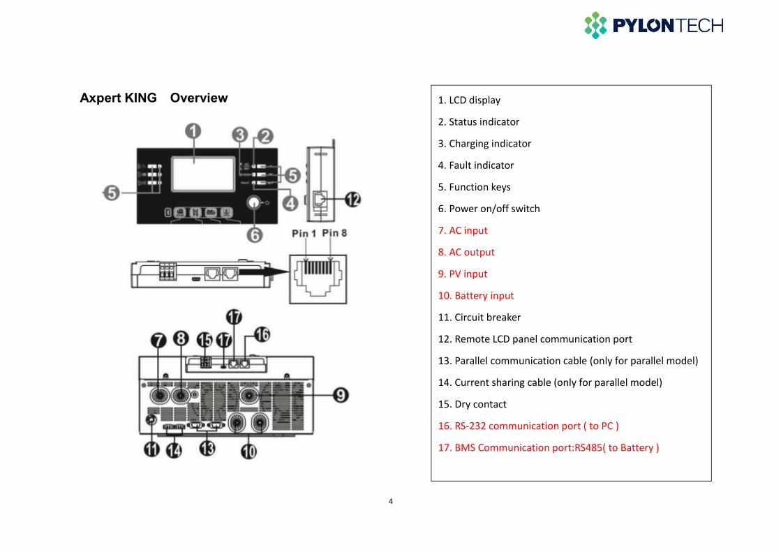
Axpert KING Overview 1. LCD display
2. Status indicator
3. Charging indicator
4. Fault indicator
5. Function keys
6. Power on/off switch
7. AC input
8. AC output
9. PV input
10. Battery input
11. Circuit breaker
12. Remote LCD panel communication port
13. Parallel communication cable (only for parallel model)
14. Current sharing cable (only for parallel model)
15. Dry contact
16. RS-232 communication port ( to PC )
17. BMS Communication port:RS485( to Battery )

5
4 . Communication Connection
Connect LCD panel to the inverter with an optional RJ45 communication cable as below chart.
Please use supplied communication cable to connect to inverter and PC. Insert bundled CD into a computer and
follow on-screen instruction to install the monitoring software. For the detailed software operation, please check user
manual of software inside of CD.

6
5 . Parameter configuration in watchpower
The setting parameters of the two Inverter types are basically the same. Charging current and working mode
are set according to on-site requirements.
5.1 Run the “WatchPower.exe”, Then click “Modbus serial setting “,select the serial Port of the device
connection in it.The Baud rate is 19200, the port name is from the Device Manager.

7
5.2 If the Basic information showed values, which means connect successfully

8
5.3 Click “Device control” button to set the parameters as below or according to site conditions.
5.4 Max.charging current: = N*20A ( N=The battery Number in parallel ). Max. charging current =
utility charging current + solar charging current.
In SBU or SUB mode,”Back to grid voltage” is recommended to set as 48 V, ”Back to discharge voltage”
is recommended to set as 52 V.

9
5.5 “Battery cut-off voltage” is recommended to set as 47 V, “C.V voltage” and “Float charging voltage” are
recommended to set as 53.2V.Other parameters setting as below. Remember to click “Apply” button after
changing parameters.

10
6 . Definitions
A: Axpert VMIII
Charger source priority:
To configure charger source
priority
CSOSolar energy will charge battery as first priority.
Utility will charge battery only when solar energy is not availabl
S∩U Solar energy and utility will charge battery at the same time.
OSOSolar energy will be the only charger source no matter utility is
available or not.
Output source priority:
To configure load power
source priority
USB
Utility will provide power to the loads as first priority.
Solar and battery energy will provide power to the loads only
when utility power is not available.
SUB
Solar energy provides power to the loads as first priority.
If solar energy is not sufficient to power all connected loads,
battery energy will supply power the loads at the same time.

11
Output source priority:
To configure load power
source priority
Utility provides power to the loads only when any one
condition happens:
- Solar energy is not available
- Battery voltage drops to “low-level warning voltage” or the
setting point in “voltage point back to utility source”.
SBU
Solar energy provides power to the loads as first priority.
If solar energy is not sufficient to power all connected loads,
battery energy will supply power to the loads at the same time.
Utility provides power to the loads only when battery voltage
drops to either “low-level warning voltage” or the setting point
in “voltage point back to utility source”.
12
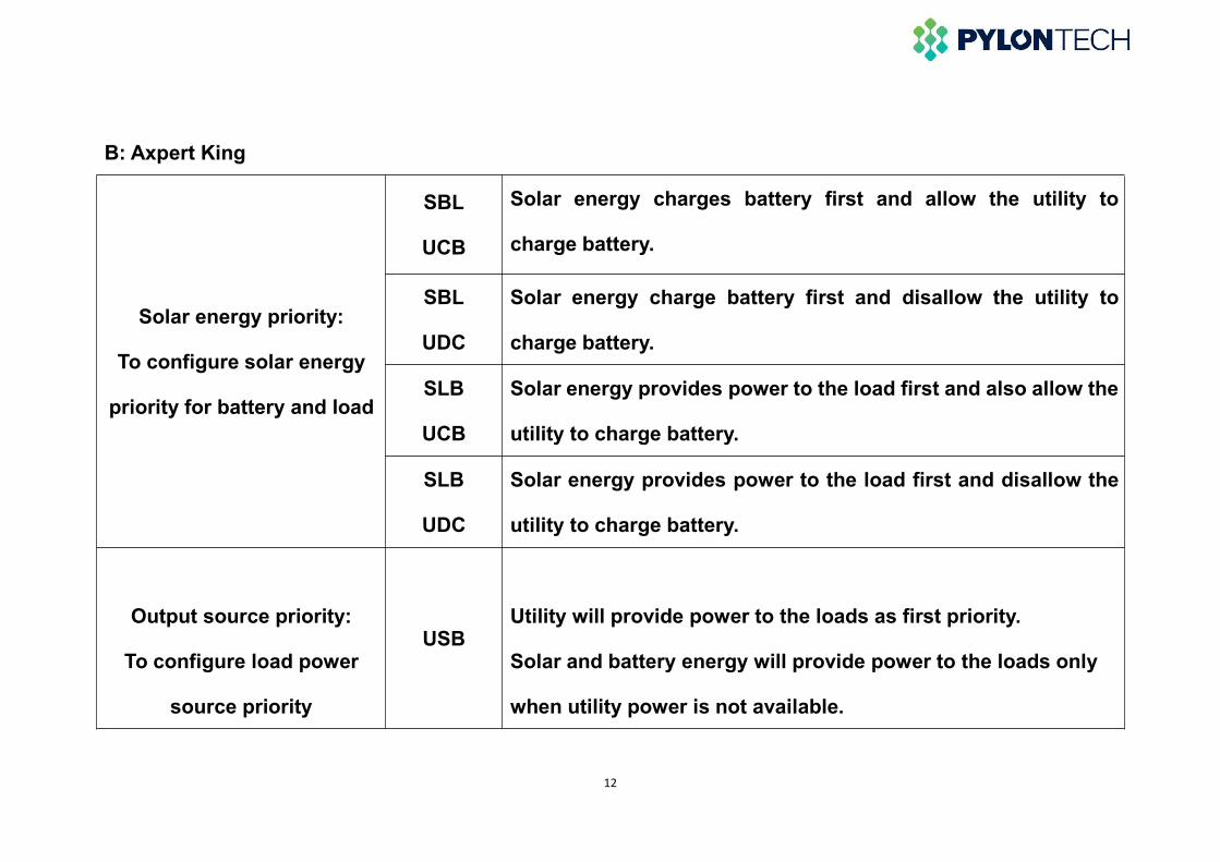
B: Axpert King
Solar energy priority:
To configure solar energy
priority for battery and load
SBL
UCB
Solar energy charges battery first and allow the utility to
charge battery.
SBL
UDC
Solar energy charge battery first and disallow the utility to
charge battery.
SLB
UCB
Solar energy provides power to the load first and also allow the
utility to charge battery.
SLB
UDC
Solar energy provides power to the load first and disallow the
utility to charge battery.
Output source priority:
To configure load power
source priority
USBUtility will provide power to the loads as first priority.
Solar and battery energy will provide power to the loads only
when utility power is not available.

13
Output source priority:
To configure load power
source priority
SUB
Solar energy provides power to the loads as first priority.
If solar energy is not sufficient ,utility energy will supply power
to the loads at the same time.Battery provides power to the
loads only when solar and utility is not sufficient.
SBU
Solar energy provides power to the loads as first priority.
If solar energy is not sufficient to power all connected loads,
battery energy will supply power to the loads at the same time.
Utility provides power to the loads only when battery voltage
drops to either “low-level warning voltage” or the setting point
in “voltage point back to utility source”.
Data:2018.12.21
Top Related