


Languages
Pages
Legal


DOCUMENT RESUME
ED 261 237 CE 042 464
TITLE Avionics. Progress Record and Theory Outline.INSTITUTION Connecticut State Dept. of Education, Hartford. Div.
of Vocational-Technical Schools.PUB DATE 84NOTE 89p.PUB TYPE Guides - Classroom Use Guides (For Teachers) (052)
EDRS PRICEDESCRIPTORS
MF01/PC04 Plus Postage.*Aerospace Education; Aerospace Technology; *AviationTechnology; Behavioral Objectives; Check Lists;Communications; Competency Based Education; ComputerScience; Electricity; *Electronics; *EquipmentMaintenance; Equipment Utilization; Guidelines; JobSkills; Measurement Equipment; MeasurementTechniques; Navigation; Postsecondary Education;*Power Technology; Programing; Radio; Recordkeeping;Secondary Education; Student Records
ABSTRACTThis combination progress record and course outline
is designed for use by individuals teaching a course in avionics thatis intended to prepare students for employment in the field ofaerospace electronics. Included among the topics addressed in thecourse are the following: shop practices, aircraft and the theory offlight, electron physics, fundamentals of electricity, Federalaviation regulations, technical math, graphics, electrical circuitsand systems, aircraft static and vacuum systems, aircraft pilotsystems, semiconductor devices, power supplies, radios and radiotransmission, test equipment and precision measurements, electronics,computers, computer programming, microprocessors, motors andgenerators, aircraft communication, navigation, flight controlsystems, and turbulence and flight collision avoidance. In additionto the theory outline, which includes space for recording informationconcerning the scheduling and presentation of the lesson material,this record book allo contains a list of course objectives and a gridfor use in recording the individual student's mastery of eachspecific skill taught in the course. (MN)
************************************************************************ Reproductions supplied by EDRS are the best that can be made *
* from the original document. *
***********************************************************************

PROGRESS ,IECORD
AND
THEORY OUTLINE
AVIONICS
DIVISION OF VOCATIONAL-TECHNICAL SCHOOLS
CONNECTICUT DEPARTMENT OF EDUCATION
1983-1984
U.S. DEPARTMENTOF EDUCATION
NATIONAL INSTITUTEOF EDUCATION
E0 CATIONAL RESOURCESINFORMATION
CENTER (ERIC,Tho document has been reproducd asroved from the
oerson of orginizahonongetahno ItLtno changes
hart boon mods al it wovereproduction qual/te
Pants of inaw Or °mons statedin the doc umerit do not nweisanly
'foment oNclaP.VIEpose on or poky
"PERMISSION TO REPRODUCE THISMATERIAL HAS BEEN GRANTED BY
I
I
TO THE EDUCATIONAL RESOURCESINFORMATION CENTER (ERIC),"
PREFACE
The objective of this Assignment Book is to
reduce unnecessary paperwork on the part of the
shop instructor.
The Avionics Assignment Book accomplishes this
by increasing the instructor's ability to plan and
organize in advance and in keeping student records
together and up to date.
A list of preferred hands-on exercises and
experiments is included to be used at the discretion
of the individual instructor.
This outline is not to be construed to be
inflexible as to the material content or order of
presentation.

GENERAL COURSE OBJECTIVES
Avionics is a program designed to,rovide vocational preparation forentry into the highly technical fieldof Aero-Space Electronics.
It provides both the theoretical back-ground and the practical skills ofservicing, installation, adjustments andtroubleshoot:mg techniques.
The course will develop in the studentskills that are necessary to enter theAvionics field at the trainee level.
The program prepares the student for theFederal Communication Commission's GeneralRadio-telephone Licensing examination.
- 2
4

PRIMARY OBJECTIVES
The student should be able to:
1. Demonstrate good safety practicesat all times.
2. Use common hand pools and powertools of the trade.
3. Use basic electron:: instruments.
4. Apply theories of electricity,electrostatics, electron physics,and magnetism.
5. Demonstrate elementary directcurrent circuits and their pro-tective devices.
6. Demonstrate basic knowledge ofaviation wiring practices andinstallation procedures.
7. Demonstrate a basic knowledge oftechnical math associated withAvionics.
8. Demonstrate a basic knowledge ofdrafting fundamentals, schematics,blueprints, and wiring diagramsassociated with Avionics.
9. Know Avionic definitions andabbreviations including FAR Part 1.
10. Demonstrate a knowledge of basicalternating current, inductance,capacitance and resonance.
11. Use basic semiconductor andintegrated circuit fundamentals.
12. Demonstrate a basic knowledge ofaviation flight instruments.
13. Demonstrate a knowledge of air-craft electrical power generationand distibut )n.
14. Demonstrate a knowledge offundamental electronic circuits.
3 5

15. Demonstrate a knowledge offundamental digital circuits.
16. Demonstrate a knowledge offundamental microprocessorcircuits.
17. Demonstrate a knowledge offundamental microprocessorinterfacing.
18. Demonstrate a knowledge ofoperation of aviation typereceivers and transmitters.
19. Demonstrate a basic knowledgeof operation of aircraftelectronics navigation devices.
20. Demonstrate a bay is 'ulowledge ofoperation of aircraft pulse andmicrowave systems.
21. Apply FAR PART 43.
22. Apply FCC regulations in regardto aviation.
23. Demonstrate a knowledge ofaircraft flight control systems.
24. Demonstrate knowledge of emergencylocation transmitters.
25. Demonstrate knowledge of VLF, LFand Loran Navigation systems.
26. Demonstrate knowledge of TurbulanceAvoidance Systems.
27. Demonstrate knowledge of Avionictransmission lines and antennasystems.
28. Demonstrate knowledge of air trafficcontrol procedures for both VFR andIFR Flying.

Strip wire
Make splices
Make wiring harness
Solder
Make wireconnectionsUse basic sheetmetAl tools
_ --
Use hand powertools
ti, Make crimpconnections
1

Generate staticelectricity
Identify sourcesof electricity
Measure volta:es
Wire simplepircuits
Measure resistance
Read resistorcolor code
I
a'
I
Install fuses
Install circuitbreakers
Install Amp Meter
9 10
t:f 0
H7'70 0Mta

Wire seriesritrwirq
Wire parallelorruir.Wire seriesparallP1
Read voltmeter
Read ammeter
Read ohmmeter
Read multimeter
Read loadingeffects
11 12
HC3CH1-3cn

Identify cells
Wire batterycircuits
Charge
Test
1
03
Identify magneticfields and pobConstruct electro-magnetDetermine magneticPolarity
13 14

Identify symbols
Make simpledrawings
Trace circuits
Develop schematics
1
1/4c)
Cut off stock
Bend stock,
Make folds
___.Fasten components/screws
Drive rivets
15 16

Use layout ink
_ADubler_RiateFabricate antenna
Fabricate audioswitch panelLayout basicinstrument panelMake instrumenthole template
1
r0I
Select and installprotective devices
Size cable
Clamp cable
Lace cable
Install solderlessennnentnrs
1718
HWC-1
H
H
HH0z
1-4
rnH 0
cnHHztjcn C-4H
H")
HHO
O
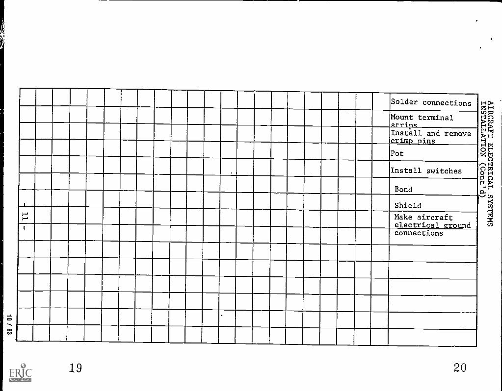
Solder connections
Mount terminalcrripqInstall and removecrime 'ins
Pot
11HM pzIH n
rl9Hhltri0 t"'Z tri0e. H
Install switches 00 74
H0 C)rt
0.,...." (f)
"4mHM
1
Bond
Shield
Make aircraftelectrical groundconnections
19
IMIN...
20

,
Generate A.G.voltage
Calibrate scope
Read voltage
Measure frequency
Calculate phasemeasurement
I-.
tv
i
Identify character-istics of inductorsConnect inductorsin seriesConnect inductorsin parallel
ConnecttrancfnrmprsMeasure R.L.impedance
2122
C)

Measure R.L. timeconstantsDemonstratesaturable reactorsCalculate induc-tance measurements
r(.0
Ident. characteristics of capacitanc=cConnect capacitors ;
in series cF
Connect capacitors 5
in parallelc
Measure R.C.impedance
Read color code
' Inspect capacitor
Measure R.C. TimeConstants

.
Identify seriesresonance circuitIdentify parallelresonance circuitIdentify filtercircuitsDetermine resonantfrequencyDetermine bandwidth
Measure diodecharacteristics
Ident. transistors
Trace curves
Wire transistorcircuits (CE.GB.CC)Measure transistorbias
25 26
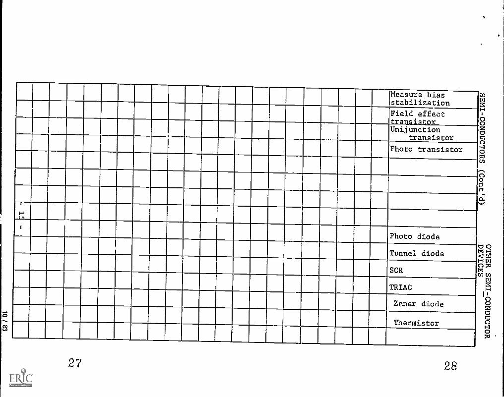
Measure biasstabilization
mXXH
o3HoPJm
IC;
o0rt
rim<Hnmm
Field effecttransistorUnijunction
transistor
Photo transistor
Photo diode
Tunnel diode
SCR
TRIAC
Zener diode
Thermistor
27 28

29
Mount wire circuitconnectionsRemove solderedchi from PC board
Make input-outputrhprks
Ident. I.C. types
30

Half waverectifiers
Full waverectifiers
Bridge rectifiers
Voltage doublers
Inverters
Filters
Regulator circuits
I-11
Construct transist-nr vnitava ampDemonstrate ampbiasing methods
Construct I.C. amp
Construct transist-nr power amp
3132
ro0
roro
Htrl
C")0zH7:1
C")H

,..__
Demonstrate coup-ling methods
Construct phasesplittersConstruct push/.ull am.
Construct compli-mentar out.utstage
Construct symmetryt lie out.ut sta:e
I-.
co
Construct R.F.amplifiers___,
.
Determine gain andfrequency responseof R.F. amp.
Construct I.F. amp
Deter. band width &gain of I.F. amp.
33 34
H0
00
rr

Audio FrequencyOscillator
P.F. Oscillator
I-,Determine wave1 n th of antennasTeststren
fthield
Install V.O.R.
- -
Install ADFantpnnnInstall glide
SO 'SO
L .
35 36
0 r.n0 HZ ZHCn DJ
1-3 <M
0r.n0Ht.
H07Jr.n
I I
>ZHZ
><M
17J00H0>1-3H0Z

Construct AM & FM ,]
transmitters
Tune and align v:
HIAMeasure modulation H
PJw
N.)0i
Construct AMupaziolat
Construct FMelirpt,
Align receiver
..
c
C
3'7 38

Demonstrate squarewave analysis ofamp i ier
Constr. neon relaxation oscillatorConstr. differentiators
Constr. integrators
1
Nt-,
Determine VOMlimitationsDetermine VTVMlimitationsDeter, solid stateVOM advantagesDeter. osciloscopeadvantagesMeasure R.F.generator
Deter, advantagesof frequencycounter tracecurves
39 40
z0zs
cnHzVI0H0

Meas. transmitterR.F. power output
Measure %,modulationOper. aviation VHFcommunicationgenerator
Oper. aviation VOR/LOC generator()per. aviationmarker receivergenerator
t.)I.>
Oper. aviation DMEgeneratorOper. aviationtransponder genera-tor
i
I
41 42

Dsaturatedemonstrate
switch
Construct inverterciuConstruct OR gate
Construct NOR gate. .
Construct NAND gat. .
Construct astablemulti-Vibratorcircuit
1111 Construct monosta e mu ti-vibrator circuit
Construct bistable1
.. r ir
Cemonstrate trig-.
. 1 e
43 44
c)0C1-3txi
CIHCICI
H1-3(/)

HRecognize0H
',1
Hz1-3
m0
Apply digital-integrated circuitsApply input-output devices
m
H0C.4
HHW
ZH20
I
I3Ps
I
For future use,dependent onavailable trainingequipment
0
c1-]
xv
4546
H0Pi0FTi
Pi00MMM0M.;.
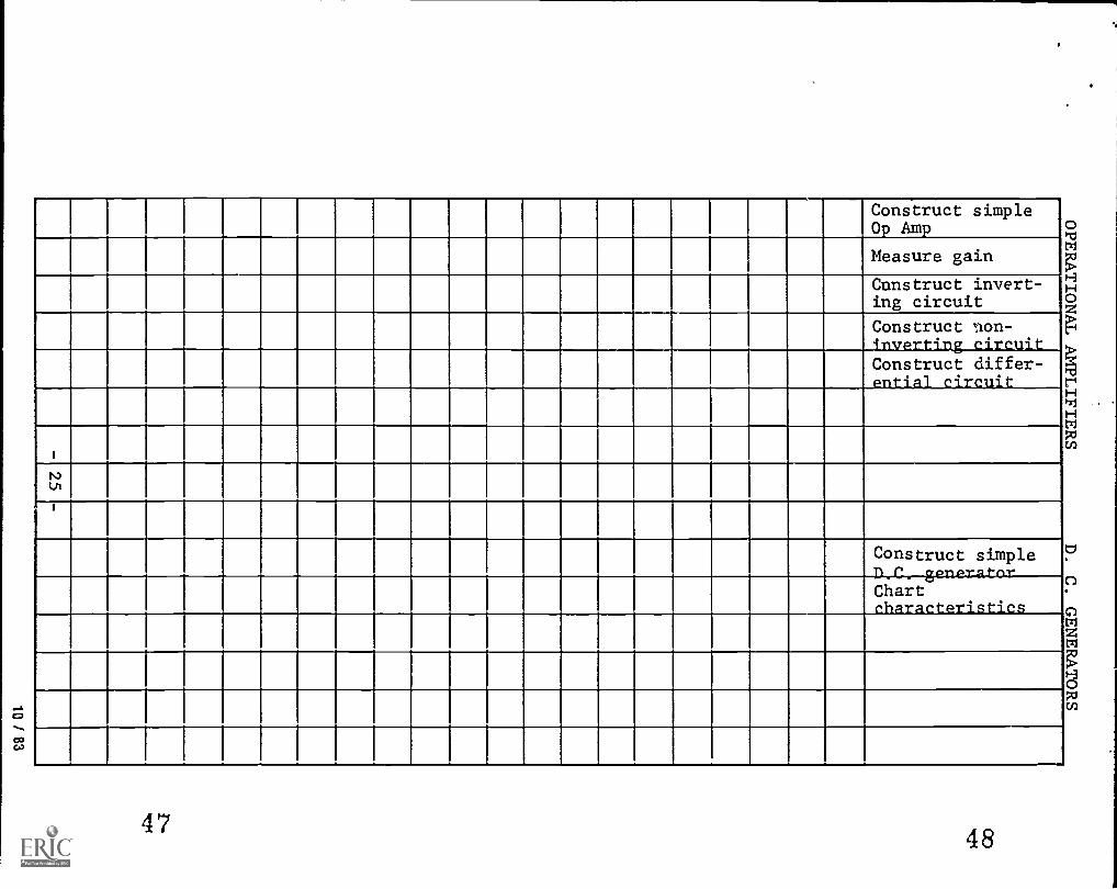
Construct simpleOp Amp o
rom
Measure gain
Construct invert-ing circuit
Hoz
HP7i
HPC,
Construct non-el
Construct differ-- .
I
lit
Construct simpleD_C. generatorChart
. . oz
ozim
4748
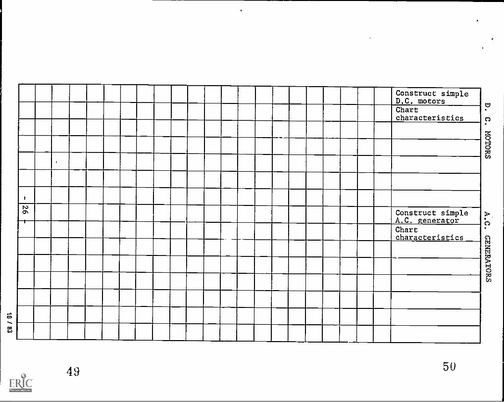
Construct simpleD.C. motorsChartcharacteristics
Construct simpleA.C. generatorChartcharacteristics
49 5U

Construct simple--A.C. motorsChartcharacteristics
,Tune & adjustVHF transmitterTune & adjustVHF receiver
-.4
Tune & adiust ,
singlesidebandtransmitter
Tune & adjustsinglesidebandreceiver
5152

Mount wire,install and
>Hcomplete FAApaperwork on:
o
1.VHF transmitter1-3
02.VHF receiver
3 Singlesideband z'transmitter H0
>yH02M
SinglesidebandLr...eceimer
I
IN.)
CO -C0
M0.
5354

TUNE & ADJUST
1. Loran C
2. VOR
3. Glide Scope
4. Marker Beacon
5. Radar
6. Radar AltimeterIVV)
7. D.M.E.
8. Transponder
MOUNT WIRE, INSTALLAND COMPLETE FAAPAPERWORK ON:
1. Loran C
2. VOR
3. Glide Scope
4. Marker Beacon
5556

5. Radar
6. Radar altimeter
7. D.M.E.
8. Transponder
LA)0
Adjust auto-pilot
Adjust integratedfli ht s stems
-4
57 58
<7c1HOOpol
1-3171Ht-30z
0rt

MAJOR UNITS OF THEORY
I. ORIENTATION
II. SHOP PRACTICES
III. AIRCRAFT FAMILIARIZATION
IV. THEORY OF FLIGHT
V. ELECTRON PHYSICS
VI. FUNDAMENTALS OF ELECTRICITY
VII. FEDERAL AVIATION REGULATIONS
VIII. TECHNICAL MATH
IX. GRAPHICS
X. D. C. CIRCUITS
XI. METERS
XII. BATTERIES
XIII. MAGNETISM
XIV. AIRCRAFT SHEETMETAL PRACTICES
XV. INSTALLATION OF ELECTRICAL SYSTEMS
XVI. A. C. FUNDAMENTALS
XVII. BASIC TRIGONOMETRY
XVIII. INDUCTANCE
XIX. CAPACITANCE
XX. RESONANCE
XXI. AIRCRAFT STATIC SYSTEM
XXII. AIRCRAFT PITOT SYSTEM
XXIII. AIRCRAFT VACUUM SYSTEM
XXIV. SEMICONDUCTOR DEVICES
XXV. OTHER SEMICONDUCTOR DEVICES
XXVI. POWER SUPPLIES
XXVII. AUDIO AMPLIFIERS
XXVIII. RADIO FREQUENCY AMPLIFIERS
XXIX. SINE WAVE OSCILLATORS
XXX. NON-SINOUSIDAL WAVEFORMS
XXXI. TRANSMITTERS
XXXII. RECEIVERS: AM AND FM
XXXIII. TEST EQUIPMENT AND PRECISION MEASUREMENTS
XXXIV. ANTENNAS AND WAVE PROPAGATION
XXXV. FCC REGULATIONS
XXXVI. INTEGRATED CIRCUITS
XXXVII. DIGITAL ELECTRONICS
- 31- 59

XXXVIII.
XXXIX.
XXYv
XXXXII.
XXXXIII.
XXXXIV.
XXXXV.
XXXXVI.
XXXXVII.
XXXXVIII.
XXXXIX.
L.
COMPUTERS
INTRODUCTION TO PROGRAMMING (SOFTWARE)
MICROPROCESSORS (HARDWARE AND SOFTWARE)
OPERATIONAL AMPLIFIERS
TRANDUCERS
MOTORS AND GENERATORS
AIRCRAFT COMMUNICATIONS
AIRCRAFT NAVIGATION
PULSE AND MICROWAVE SYSTEMS
FLIGHT CONTROL SYSTEMS
TURBULANCE AVOIDANCE
FLIGHT COLLISION AVOIDANCE
AIR TRAFFIC CONTROL PROCEDURES
- 32-60

THEORY OUTLINE
ORIENTATION
A. Occupational Analysis
1. Development of the Avionics Industry2. Employment opportunities3. Employment requirements and trade
practices4. Federal Aviation Administration5. Federal Communication Commission
II. SHOP PRACTICES
A. Care and Use of Common Hand Tools1. Saietv
B. Care and Use of Air and Electric PowerTools
1. Safety
C. Wire Stripping, Splicing and SolderingTechniques
1. Safety
D. Safety Around Aircraft
1. Propeller2. Fuel3. Jet intake and exhaust4. Helicopter blades and tail rotor5. Aircraft wing and tail surfaces6. Retractable gear
III. AIRCRAFT FAMILIARIZATION
A. Types
1. Fixed wing
a. Singleb. Multic. Gliderd. Ultra light
2. Rotor Craft
a. Helicopterb. Autogyro
3. Lighter than air
- 33- 61
z
z0U)cnr. 0
zPw
nc4

B. Construction
1. Metal2. Wood3. Fabric4. Fiberglass
C. Cockpit
1. Instrument panel2. Controls3. Cockpit safety
D. Power Plants
1. Piston2. TurboDron3. Turbine4. Safety
IV. THEORY OF FLIGHT
A. Aircraft Controls
B. Forces on Airplane in Flight
C. Load Factors and Safety
V. ELECTRON PHYSICS
A. The Nature of Matter
1. States and forms of matter
a. Moleculeb. Atomc. Compoundd. Element
B. Atomic Structure
1. Sub-atomic particles
a. Chargesb. Physical arrangement
2. Differences between atoms
a. Conductors and non-conductorsb. Stable :Ind unstable atomsc. Neutral atoms and ions
-34- 62
zaa.
z0cnCl) 0g
C:)
a
4141
A Cl)0
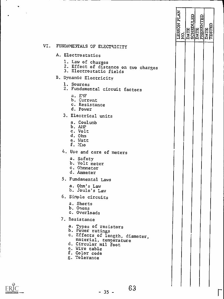
VI. FUNDAMENTALS OF ELECTRICITY
A. Electrostatics
1. Law of charges2. Effect of distance on two charges3. Electrostatic fields
B. Dynamic Electricity
1. Sources2. Fundamental circuit factors
a. EIFb. Currentc. Resistanced. Power
3. Electrical units
a. Coulumbb. AIIPc. Voltd. Ohme. Wattf.
4. Use and care of meters
a. Safetyb. Volt meterc. Ohmmeterd. Ammeter
5. Fundamental Laws
a. Ohm's Lawb. Joule's Law
6. Simple circuits
a. Shortsb. Ovensc. Overloads
7. Resistance
a. Types of resistorsb. Power ratingsc. Effects of length, diameter,
material, temperatured. Circular mil foote. Wire tablef. Color codeg. Tolerance

VII. FEDERAL AVIATION REGULATIONS
A. Part 1
B. Part 43
C. Part 65
D, Part 91
E. Part 145
VIII. TECHNICAL MATH
A. Signed Numbers
1. Addition2, Subtraction3. Multiplication4. Division
B. Power of Ten
1. Positive and negative exponents2. Common electronic prefixes
a. MEG, KILO, MILLIb. MICRO, NANO, PICO
3. Multiplication and division
C. Electronic Calculator
1. Multiplication2. Division3. Square roots4. Trig functions5. Memory
IX. GRAPHICS
A. Drafting Fundamentals
1. Aircraft electrical symbols2. Blueprints3. Wiring diagrams
X. D. C. CIRCUITS
A. Series Circuits
1. Definition2. Basic rules
- 36- 64
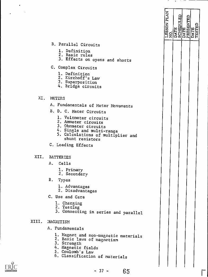
B. Parallel Circuits
1. Definition2. Basic rules3. Effects on opens and shorts
C. Complex Circuits
1. Definition2. Kirchoff's Law3. Superposition4. Bridge circuits
XI. METERS
A. Fundamentals of Meter MovementsB. D. C. Meter Circuits
1. Voltmeter circuits2. Ammeter circuits3. Ohmmeter circuits4. Single and multi-range5. Calculations of multiplier and
shunt resistors
C. Loading Effects
XII. BATTERIES
A. Cells
1. Primary2. Secondary
B. Types
1. Advantages2. Disadvantages
C. Use and Care
1. Charging2. Testing3. Connecting in series and parallel
XIII. MAGNETISM
A. Fundamentals
1. Magnet and non-magnetic materials2. Basic laws of magnetism3. Strength4. Magnetic fields5. Coulomb's Law6. Classification of materials
- 37 - 65
z
z0U)CDrs1 0Z

B. Electromagnetism
1. Definition2. Fundamentals
a. Strength and directionb. Left hand rule
XIV. AIRCRAFT SHEETMETAL PRACTICES
A. Tools
1. Floor and bench
a. Shearsb. Nibbling mac'iinec. Breaksd. Band sawe. Drill press
2. Hand air and electric power tcols
a. Drillsb. Screwdriversc. Sheetmetal shtzarsd. Sabre sawse. Grindersf. Rivet tools
3. Hand tools
a. Hammersb. Hand snips and shearsc. Malletsd. Punchese. Hand rivet setf. Chiselsg. Dividersh. Pliersi. Rulersj. Wire and sheetmetal gagesk. Hacksaw1. Scribem. Files
4. Riveting
a. Typesb. Rivet codec. Temper designationd. Installing rivets
- 38- 66

5. Riveting Practices
a. Sizesb. Spacingc. Number of rivets requiredd. Dimensionse. Bucking barf. Use of rivet gung. Sheet fastenersh. Removing rivets
6. Special Rivets
a. Needb. Types
XV. INSTALLATITI OF ELECTRICAL SYSTEMS
A. Electrical System Requirements
1. 'eneral2. Protective devices3. Safety and emergency4. Electrical load
B. Electrical Wiring
1. Cable characteristics2. Cable size3. Current carrying capacity4. Requirements for open wiring5. Cable lacing6. Cable clamping7. Routing of electrical cable8. Electrical conduit
C. Connecting Devices
1. Cable terminals
a. Crimp terminalsb. Solder terminalsc. Advantages and disadvantages
2. Connectors
a. Solder connectorsb. Crimp connectorsc. Advantages and disadvantages
3. Electrical terminal strins
a. Solder typeb. Screw lug typec. Punch nip type
4. Potting

D. Switches and relays
E. Circuit protecting devices
1. Fuses2. Circuit breakers3. Over voltage cutouts
F. Bonding and sheilding
G. Wire identification
1. Adhesive tane2. Heat shrink tubing labels3. Hot stump labeling
H. Typical systems
1. Simple electrical systems2. Alternator circuits3. Battery and starter circuits
XVI. A. C. FUNDAMENTALS
A. Definition
B. Generation of AC
1. Lenz's Law2. Left hand rule3. Fundamental factors needed to
generate a voltage4. Factors determining the strength
of induced E.M.F.5. Terms
a. Cycle, alternation, periodb. Frequency, Hertz, wavelengthc. Instantaneous, peak, and adveraged. Phase angle
6. Introduction to Oscilloscopes
a. Basic operationb. Voltage measurementse. Frequency measurementsd. Lissajous patternse. Calibrationf. Phase angle measurements
-40- 68

XVII. BASIC TRIGONOMETRY
A. Angles
1. Definition2. Types
B. Triangle
1. Definition2. Types
C. Right Triangle
1. Definition2. Hypotenuse3. Pythagorean Thorem4. Trigonometric functions5. Problem solving
D. Vectors
1. Definition2. Use in electronics3. Problem solving
XVIII. INDUCTANCE
A. Inductance by AC
B. Lenz's Law
C. Impedance and reactance
D. Inductance in Series and Parallel
E. Mutual Inductance
F. R. L. Circuits, Series and Paralle2P
G. Power Factor
H. Time Constants
I. Q
J. Losses in Coils
1. D.C. Resistance2. Effective Resistance3. Radiation Losses4. Effect of coil shields
- 41 - 69
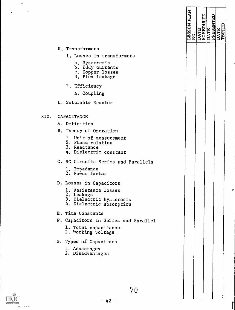
K. Transformers
1. Losses in transformers
a. Hysteresisb. Eddy currentsc. Copper lossesd. Flux leakage
2. Efficiency
a. Coupling
L. Saturable Reactor
XIX. CAPACITANCE
A. Definition
B. Theory of Operaticn
1. Unit of measurement2. Phase relation3. Reactance4. Dielectric constant
C. RC Circuits Series and Parallels
1. Impedance2. Power factor
D. Losses in Capacitors
1. Resistance losses2. Leakage3. Dielectric hysteresis4. Dielectric absorption
E. Time Constants
F. Capacitors in Series and Parallel
1. Total capacitance2. Working voltage
G. Types of Capacitors
1. Advantages2. Disadvantages
70-42-
Aw
A
eC 0A co
PEw
mu)
A a
aA

XX. RESONANCE
Ca q
zA 4.1
WqActin 0w
(1)
O Aa
A
"A
A. Series and Parallel
B. Vector Analysis
C. Q
D. Bandwith
E. Applications
1. Filter circuits
a. Highpassb. Lowpassc. Pi typed. Band passe. Band elimination
XXI. STATIC SYSTEMS
A. Static ports
B. Plumbing techniques
C. Instruments
1. Altimeter2. Vertical air speed3. Encoding altimeter4. Autopilot altitude hold chamber5. Air speed6. Alternate air source7. Required tests
D. Safety
XXII. PITON SYSTEM
A. Pitot tube
1. Function2. Pitot tube heat
B. Plumbing techniques
C. Instruments
1. Airspeed2. Flight directors
D. Safety
71- 43 -
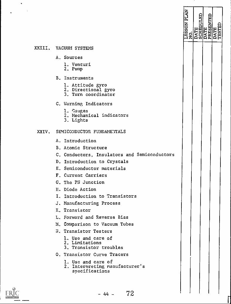
XXIII. VACUUM SYSTEMS
A. Sources
1. Venturi2. Pump
At
B. Instruments
1. Attitude gyro2. Directional gyro3. Turn coordinator
C. Warning Indicators
1. Gauges2. Mechanical indicators3. Lights
XXIV. SEMICONDUCTOR FUNDAME1TALS
A. Introduction
B. Atomic Structure
C. Conductors, Insulators and Semiconductors
D. Introduction to Crystals
E. Semiconductor materials
F. Current Carriers
G. The PN Junction
H. Diode Action
I. Introduction to Transistors
J. Manufacturing Process
K. Transistor
L. Forward and Reverse Bias
M. Comparison to Vacuum Tubes
N. Transistor Testers
1. Use and care of2. Limitations3. Transistor troubles
0. Transistor Curve Tracers
1. Use and care of2. Interpreting manufacturer's
specifications
- 44 - 72

P. Common Base Amplifier
Q. Common Collector Amplifier
R. Common Emitter Amplifier
S. Transistor Circuit Parameters
T. Transistor Bias Stabilization
U. Power Transistors
V. Other Transistor Types
1. FET2. Surface Barrier3. Unijunction4. MESA5. Enitaxial6. Photo
XXV. OTHER SEMICONDUCTOR DEVICES
A. Photo Diodes
B. Tunnel Diodes
C. Silicon Controlled Rectifiers
D. Triacs
E. Zener Diodes
F. Thermistors
XXVI. POWER SUPPLIES
A. Half-wave
B. Full-wave
C. Bridge
D. Voltage Doublers
E. Positive and Negative Supplies
F. Filters
G. Voltage Dividers
H. Voltage Regulator Circuits
Voltage Regulator Devices
J. DC to AC Inverters
73-45-

XXVII. AUDIO AMPLIFIERS
A. Voltage Amplifiers
1. Basic operation2. Classes of oneration3. Coupling methods4. Biasing methods5. Response curve6. Distortion7. I. C. Amplifiers
B. Power Amplifiers
1. Purpose2. Output stages3. Tone controls4. Decibles
XXVIII. RADIO FREQUENCY AMPLIFIERS
A. R. F. Losses
B. Functions of R.F. Amplifiers
C. Typical RF Amplifiers
D. Coupling methods
E. Shunt damping
F. Grounded base
G. Cascode
H. Cascade
I. Wire Band Amplifiers
J. Mechanical Filters
K. Crystal Filters
L. I. F. Amplifiers
XXIX. SINE UAVE OSCILLATORS
A. Oscillator Requirements
B. Oscillator Operation
C. Phase-shift Oscillators
D. Tickler-coil Oscillators
E. Colpitts Oscillator
F. Electron-coupled Oscillator
G. Tuned-grid, Tuned-plate Oscillator
U. Crystal Oscillator
74-46-
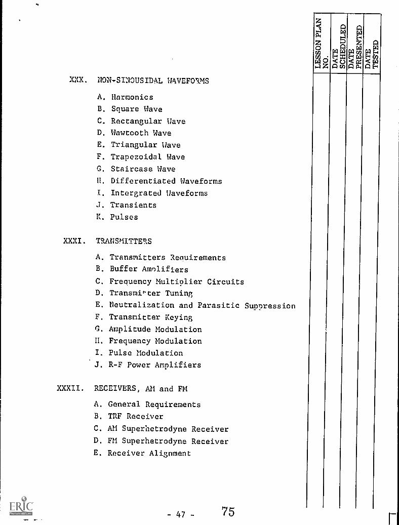
XXX. NON-SINOUSIDAL WAVEFORMS
A. Harmonics
B. Square Wave
C. Rectangular Wave
D. Wawtooth Wave
E. Triangular Wave
F. Trapezoidal Wave
G. Staircase Wave
H. Differentiated Waveforms
I. Intergrated Waveforms
J. Transients
K. Pulses
XXXI. TRANSMITTERS
A. Transmitters Requirements
B. Buffer Amplifiers
C. Frequency Multiplier Circuits
D. Transmi*ter Tuning
E. neutralization and Parasitic Suppression
F. Transmitter Keying
G. Amplitude Modulation
H. Frequency Modulation
Pulse Modulation
J. R-F Power Amplifiers
XXXII. RECEIVERS, AM and FM
A. General Requirements
B. TRF Receiver
C. AM Superhetrodyne Receiver
D. FM Superhetrodyne Receiver
E. Receiver Alignment
- 47 - 75

XXXIII. TEST EQUIPMENT AND PRECISION MEASUREMENTS
A. Introduction to Standardized Calibration
1. National Bureau of Standards
a. Measurement Nomenclature
1. Absolute2. Secondary3. Working standards
B. Basic Standards and Measurements
C. Operational Standards and Calibration
1. Volt-Ohm-Milliameter2. Vacuum tube voltmeter3. Solid state voltmeter4. L-C-R Measurements5. Oscilloscopes6. All purpose signal generators7. Aviation signal generators8. Tube and semiconductor testers9. Miscellaneous test instruments
XXXIV. ANTENNAS AND WAVE PROPAQATION
A. Electromagnetic Waves
1. Frequency Spectrum
B. Antenna Types
1. Longwire2. Whip3. Broadband4. Electronic
XXXV. FCC REGULATIONS
A. Licensing Requirements
1. Personnel2. Station
B. Performance Standards
1. Frequency tolerance2. Percent modulation
-48-76
z<..1cl
zaU,. .
N 2
AMzW
r=3
AP,dtg Mr:
AM
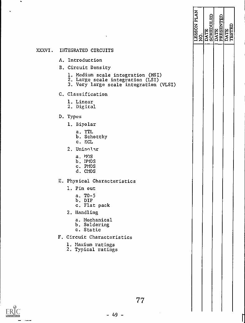
XXXVI. INTEGRATED CIRCUITS
A. Introduction
B. Circuit Density
1. Medium scale integration (MSI)2. Large scale integration (LSI)3. Very large scale integration (VLSI)
C. Classification
1. Linear2. Digital
D. Types
1. Bipolar
a. TTLb. Schottkyc. ECL
2. Uninnilr
a. MOSb. HMOSc. PMOSd. CMOS
E. Physical Characteristics
1. Pin out
a. TO-5b. DIPc. Flat pack
2. Handling
a. Mechanicalb. Solderingc. Static
F. Circuit Characteristics
1. Maxium ratings2. Typical ratings
77
-49-
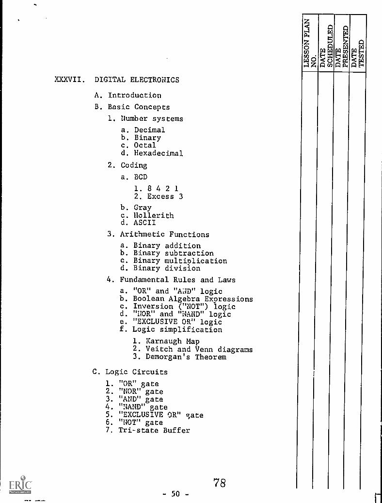
XXXVII. DIGITAL ELECTRONICS
A. Introduction
B. Basic Concepts
1. Number systems
a. Decimalb. Binaryc. Octald. Hexadecimal
2. Coding
a. BCD
1 . 8 4 2 12. Excess 3
b. Grayc. Hollerithd. ASCII
3. Arithmetic Functions
a. Binary additionb. Binary subtractionc. Binary multiplicationd. Binary division
4. Fundamental Rules and Laws
a. "OR" and "AND" logicb. Boolean Algebra Expressionsc. Inversion ("NOT") logicd. "NOR" and "NAND" logice. "EXCLUSIVE OR" logicf. Logic simplification
1. Karnaugh Map2. Veitch and Venn diagrams3. Demorgan's Theorem
C. Logic Circuits
1. "OR" gate2. "NOR" gate3. "AND" gate4. "NAND" gate5. "EXCLUSIVE OR" gate6. "NOT" gate7. Tri-state Buffer
78- 50 -

D. Logic Circuit Characteristics
1. Logic2. Power dissipation3. Transient Response4. Propagation time5. Fan-out
E. Regenerative Switching Circuits
1. Astable multivibrator (clock)2. Monostable multivibrator (one-shot)3. Bistable multivibrator (flip -floe)
a. T flip-flopb. RS and RST flip -flopc. Clocked RD flip-flopd. D flip-flope. J-K Flip-flop
F. Applications
1. Counters
a. Ripple counterb. Modulo 0c. Synchronousd. Up-downe. Preset and self-stoppingf. Ringg. Frequency dividers
2. Shift registers
a. Serial -Loadb. Parallel loadc. Shift left- shift rightd. Rotate left/righte. Arithmetic
3. Arithmetic Circuits
a. Adders
1. Half2. Full
b. Subtractors
1. Half2. Full
79
3. Adders as subtractors
a. Two's complementb. Sign bitc. Multipliersd. Dividerse. Serial addersf. Parallel adders
G. Converters
1. Digital/Analog (D/A)2. Analog/Digital (A/D)
H. Memories
1. Memory Types
a. RAM
1. Static2. Dynamic3. Bubble
b. ROM
1. ROM2. PROM3. EPROM4. EEPROM
2. Bulk Storage Devices
a. Magnetic
1. Core2. Tape3. Drum4. Disc
a. Floppyb. Hard
b. Mechanical
1. Punch card2. Paper tape
- 52-
80
PgAu)

XXXVIII. COMPUTERS
A. Introduction
1. Analog2. Digital3. Hardware4. Software
B. Terms and Conventions
1. Microprocessor vs Microcomputer2.. Stored program concept3. Computer words4. Word length
a. Byteb. Nibble
5. Baud rate6. Bi-directional busing
a. Tri-state buffersb. Timingc. Shared address and data bus
C. Basic Computer System
1. Block diagram
a. CPUb. Periperal devices
1. Definition (I /O)2. CRT display
. 3. Keyboard4. Memory5. Sensors6. Printers
D. Elementary Microcomputer
1. Microprocessor Unit (MPU)2. Memory3. Executing a program
a. Fetch phaseb. Execute phasec. Fetch/Execute a typical instruction
0U)W 0rzl
Z

XXXIX. INTRODUCTION TO PROGRAMMING (SOFTWARE)
A. Introduction
B. Languages
1. Low order
a. Machineb. Assembly
C. Flow Charting
1. Purpose2. Symbols used3. Logical sequences
a. Straight-lipc programsb. Branching programs
1. Unconditional2, Conditional
XXXX. MICROPROCESSORS (HARDWARE AND SOFTWARE)
A. Introduction
B. Microprocessor Architecture
1. CPU Block diagram (Programming model)2. Characteristics3. Typical microprocessors
C. Instructio.i Set
1. Ad4ressiug Modes
a. Immediateb, Directc. Relatived. Inherent or impliede. Indexedf. Extended
2. Data Handling
a. Moving Data
1. Into CPU Registers2. Into memory locations3. Out of CPU registers4. Out of memory locations
b. Arithmetic operationsc. Logic operationsd. Stack operations
- 54 - 82
z. a
'.1
l.4
,,,z aEn NP4'aci

e. Condition Code or Flagregister operation
f. Branching
1. Unconditional2. Conditional3. Subroutines
a. Jump to Subb. Conditional jumpe. Nested subroutine
g. Interrupt',
1. Reset2. Non-mskable3. Retury from interrupt4. Interrupt request.5. Interrupt mask6. Wait for interrupt
h. Input-Output (I/O)
1. Input2. Output3. I/O Programming4. Program control of I/O5. Interrupt control of I/O
D. Interfacing
1. Fundamentals
a. Busesb. Tri-state logicc. MPU interface linesd. Instruction timinge. Timing of program segmentf. Data sheet
2. Interfacing Memory
a. RAM
1. Static2. Dynamic
b. ROMc. Configurations of RAM
1. 128-word by 8-bit2. 256-word by 4-bit
d. Connecting RAM to MPUe. Address decoding
- 55-83

z<a
Z Z A0 A rz) ril
cncn w Ptrii4,0 44044,4
?,'...1z Acn A a4
3. Interfacing with Displays
a. The 7-segment displayb. Driving the 7-segment displayc. Using an addressable latchd. Multiplexing displays
4. Interfacing with Switches
a. Interfacing requirementsb. A typical keyboard
5. The Peripheral Interface Adapter (PIA)
a. I/O diagramb. PIA registersc. Addressing ne registers in the PIAd. Initializing the PIAe. Addressing the PIA
6. Using the PIA
a. Driving 7-segment displaysb. Decoding keyboardsc. Decoding a switch matrix
E. Troubleshooting Microcomputer Circuits
1. Trouble Symptom Analysis
a. Block diagramb. Diagnostic programc. Chip location guided. Schematic
2. Changing Chips
a. Extraction techniquesb. Insertion techniquesc. Static electricity precautionsd. Soldering precautions
3. Common Problems
a. Power Supply
1. Low or missing voltages2. Excessive ripple
b. Clock
1. No clock pulses2. Clock pulses out of phase
c. Defective busesd. Memory chips
- 56 - 84

AP
F. Microprocessor Applications
1. Transmitters2. Receivers3. Test equipment4. Navigation aids
a. RNAVb. DMEc. Transponderd. Loran Ce. Radar
5. Autopilot
XXXXI. OPERATIONAL AMPLIFIERS
A. Fundamental Circuit Theory
1. Operational model2. Symbols3. Idealized characteristics
B. Electrical Specifications
1. Minimum and maximum vs. typical2. Definitions
a. Rated outputb. Open loop gainc. Unity gain bandwidthd. Slew ratee. Full power response and settling timef. Voltage offsetg. Noiseh. Input and output impedancei. Common mode rejection
C. Linear Circuits
1. Inverting amplifier2. Non-inverting amplifier3. Voltage follower4. Mixers5. Current amplifier6. Differential amplifier
D. Digital Circuits
1. Comparator2. Inverting adder3. Non-inverting adder
- 57 - 85i

E. Special Applications
1. Voltage to current converter2. Current to voltage converter3. Constant current source4. Phase shifter
F. Generator Circuits
1. Free running multivibrator2. One shot multivibrator3. Ramp generator4. Triangular wave generator5. Saw tooth generator6. Voltage to frequenty converter7. Adjustable timer
4G. 555 Timer
1. Introduction2. Terminals3. Free running4. One shot5. Timer6. Programmable timer
XXXXII. TRALISDUCERS
A. Introduction
B. Motion Sensors
C. Force Sensors
D. Fluid Sensors
1. Pressure2. Differential-pressure3. Flow4. Level
E. Temperature Sensors
1. Fluid temperature2. Resistive3..Bimetallic4. Thermocounle5. Radiation pyrometers
86- 53-

F. Radiation Sensors
1. Light2. X-ray3. Radioactivity
G. Thickness Sensors
H. Proximity Sensors
I. Moisture-content Sensors
J. Density Sensors
K. PH Sensors
XXXXIII. MOTORS AND GENERATORS
A. D. C. Generators
B. A.C. Generators
C. D.C. Motors
D. A.C. Motors
E. Motor Controls
XXXXIV. AIRCRAFT COMMUNICATIONS
A. VHF Transmitters
B. VHF Receivers
C. HF Transmitters
D. HF Receivers
E. LF Transmitters
F. LF Receivers
G. SSB
H. ELT
I. P.A. Syst msr
87...' -59-
aa.
Z0cncnril
Z0
-1
A
zw2g<
A a.

XXXXV. AIRCRAFT NAVIGATION
A. VLF Frequency / LF
1. Omega2. INS
B. Loran C
C. Inertial Guidance
D. Very High Frequency
1. VOR2. ILS
a. Localizerb. Glide Scopec. Marker Beacon
3. Area navigation
E. Magnetic Compass System
F. Directional Gyro
XXXXVI. PULSE AND MICROWAVE SYSTEMS
A. Radar Systems
B. Radar Altimeter
C. D. M. E.
D. Transponders
E. Encodering Altimeter
XXXXVII. FLIGHT CONTROL SYSTEMS
A. Automatic Pilots
B. Altitude Gyros
1. Wing levelers2. 2 axis3. 3 axis
C. Integrated Flight Systems
1. Artificial Horizon2. Horizontal situation indicator
- 60 -88

I
XXXXVIII. TURBULANCE AVOIDANCE
A. Weather radar
B. Low Frequency Static Discharge
XXXXIX. FLIGHT COLLISION AVOIDANCE
A. Radio altimeter
B. Air to air
L. AIR TRAFFIC CONTROL PROCEDURES
A. History
B. Function
1. VFR2. IFR
Top Related