


Languages
Pages
Legal


Automatic
Valves
The solution you’ve been looking for

2
Automatic
Valves
Over 50,000 Larox valves are currentlyoperating in mining and metalindustries, minerals processing, pulpand paper, chemical processindustries, energy as well as oil andoffshore industries. Numerousapplications also exist in water andeffluent treatment, dairy, food andbeverage production, andpharmaceutical processing plants.
Modular design
Our modular valve design has threemain components: the sleeve, thebody and the actuator. The sleeve isthe only part that is in contact with theprocess medium. The constructionand materials of all three main
components can be tailored to suitmost process conditions. Self-cleaningLarox valves provides 100% tight shut-off even if solids have built up on thesleeve wall. When compressed, anycrystallized particles flake off thesleeve surface and are washeddownstream.
The standard range is for diametersfrom 25 mm to 1,000 mm, tempera-tures from -50°C to +160°C, andoperating pressures from vacuum to100 bar.
We provide tailor-made flow controlsolutions precisely in accordance withthe customer specifications.
Larox automatic valves
Larox automatic valves are ideal for shut off or controlapplications that involve abrasive or corrosive slurries,powders or granular substances. Our advanced flow controlsolutions meet even the most stringent customerspecifications. Larox valves offer substantial savings throughimproved performance, longer service lifetime and lowermaintenance costs.
Technical
features
• 100% Tight
• Full Bore
• Only the Sleeve isin Contact with the Medium
• Linear Control Curve
• Centerline Closing
• Flexible Sleeve
Process
benefits
• Excellent Wear Resistance
• High Corrosion Resistance
• No Jamming orClogging
• Self-cleaning
• Trouble-freeOperation
• Long ServiceIntervals
• Low MaintenanceCosts
• Reduced Cost of Ownership
The operating principle of a Larox valve is simple. In the open position, the valve is at fullbore with no flow restrictions thus making the valve an integral part of the pipeline. Duringclosing, two pinch bars squeeze the sleeve shut on the centerline.
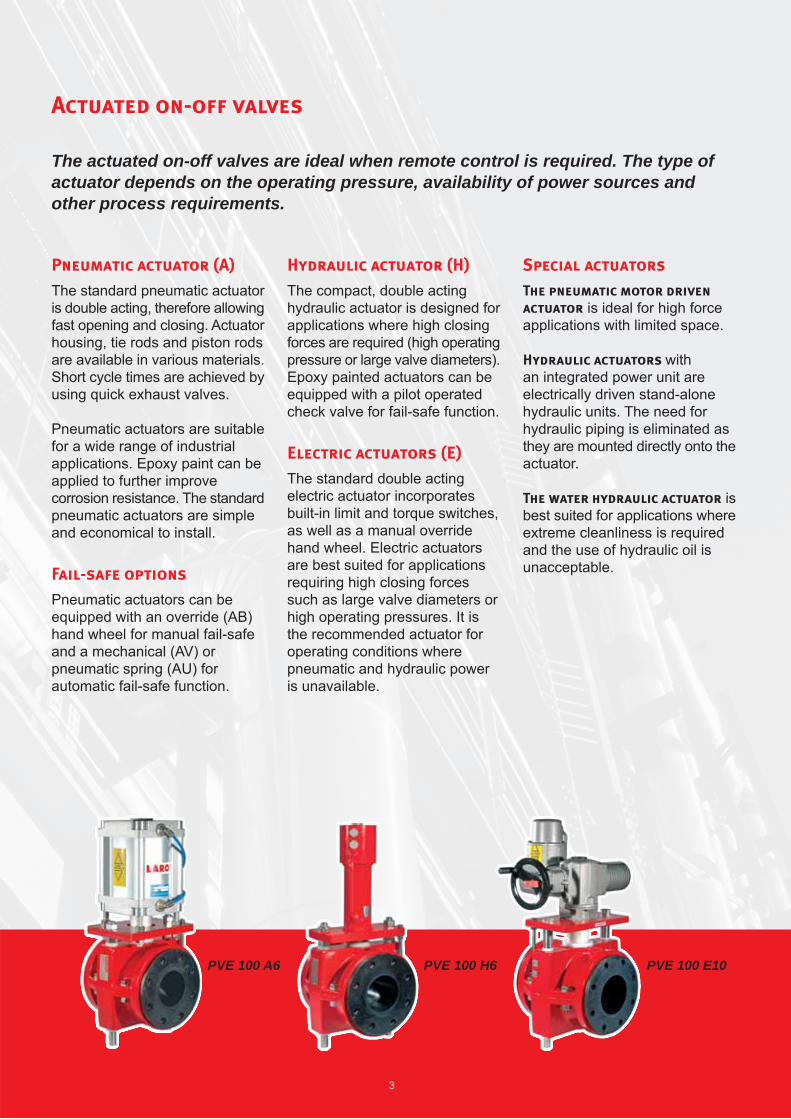
Actuated on-off valves
The actuated on-off valves are ideal when remote control is required. The type ofactuator depends on the operating pressure, availability of power sources andother process requirements.
3
PVE 100 A6 PVE 100 H6 PVE 100 E10
Pneumatic actuator (A)
The standard pneumatic actuatoris double acting, therefore allowingfast opening and closing. Actuatorhousing, tie rods and piston rodsare available in various materials.Short cycle times are achieved byusing quick exhaust valves.
Pneumatic actuators are suitablefor a wide range of industrialapplications. Epoxy paint can beapplied to further improvecorrosion resistance. The standardpneumatic actuators are simpleand economical to install.
Fail-safe options
Pneumatic actuators can beequipped with an override (AB)hand wheel for manual fail-safeand a mechanical (AV) orpneumatic spring (AU) forautomatic fail-safe function.
Hydraulic actuator (H)
The compact, double actinghydraulic actuator is designed forapplications where high closingforces are required (high operatingpressure or large valve diameters).Epoxy painted actuators can beequipped with a pilot operatedcheck valve for fail-safe function.
Electric actuators (E)
The standard double actingelectric actuator incorporatesbuilt-in limit and torque switches,as well as a manual overridehand wheel. Electric actuatorsare best suited for applicationsrequiring high closing forcessuch as large valve diameters orhigh operating pressures. It isthe recommended actuator foroperating conditions wherepneumatic and hydraulic poweris unavailable.
Special actuators
The pneumatic motor driven
actuator is ideal for high forceapplications with limited space.
Hydraulic actuators withan integrated power unit areelectrically driven stand-alonehydraulic units. The need forhydraulic piping is eliminated asthey are mounted directly onto theactuator.
The water hydraulic actuator isbest suited for applications whereextreme cleanliness is requiredand the use of hydraulic oil isunacceptable.

*) Fe DN25-200: GRS 250 (EN-GJL-250), epoxy painted K18-E180/2-FeSa 2ΩDN250…: fabricated Fe37B (EN 10025 S235JRG2), epoxy painted K180-E180/2-FeSa 2Ω
AISI 316 DN25-200: casted (EN 10213-4 1.4408)DN250…: fabricated (EN 10088-2 1.4432)
Aluminium DN25-150: aluminium alloy (EN 1706 EN AC 44200) epoxy painted K18-E180/2-FeSa 2Ω
Plastic Ciba 5000 series DN65---150; PA Blend DN250
4
R Z
S QPV PVE PVE/S PVS
Valve model selection
Example: PVE100AK10 - 203LR
PVE
type
PV =open
PVE =enclosed
PVE/S =enclosed/sealed
PVS =sealed
100
size
(DN)
25-1000
AK
actuator
M = handwheel
A = pneumatic
AB = with manualoverride
AK = withel.pneum.positioner
AN = with pneum.positioner
AU = with pneum.spring
AV = with mech.spring
H = hydraulic
HP = withhydraulicpositioner
E = electric
EO = electric forcontrol
10
pressure
classes
(PN)
1= 1 bar
6= 6 bar
10= 10 bar
16= 16 bar
25= 25 bar
40= 40 bar
64= 64 bar
100 = 100 bar
2
flange
drillings
1 = -
2 = DINPN 10
3 = DINPN 16
4 = DINPN 25
5 = DINPN 40
6 = ANSI 150
7 = ANSI 300
8 = BSTABLE D
9A = ASTABLE D
9B = ASTABLE E
9C = JIS 10
9D = JIS 16
Other on request
0
body
material
*
0 = Fe
1 = -
2 = AISI 316
3 = aluminium
4 = other
5 = plastic
3
flange
shape
types 1 - 4
Determinedby the valvemanufacturer
R
auxiliaries
Q = quickexhaustvalve
R = inductivelimits
S = magneticlimits
T = mechan.limits
Z = solenoidvalve
X = other,must be specified
L
opening
tags
L = openingtags
-

5
Sleeve model selection
Example: SBRT 10100/250/3L2
Opening tags
Reinforcing cords
Wear-resistant inner lining
SBRT
sleeve materials
SBRT = styrene butadiene
EPDM= ethylene propylene
CR = chloroprene
CSM = chloro-sulphone-ethene
FPM = fluorine rubber
HNBR= hydrogenated nitrile
IIR = butyl
NBR = nitrile
NBRF = nitrile foodstuffquality
NR = natural rubber
NRF = natural rubberfoodstuff quality
PU = polyurethane
_/PU = PU coatinginside the sleeve
_/M = Larox SensoMatesleeve
10
pressure
classes (PN)
1 = 1 bar
6 = 6 bar
10 = 10 bar
16 = 16 bar
25 = 25 bar
40 = 40 bar
64 = 64 bar
100 = 100 bar
100
sleeve
inner
diameter
(MM)
25 - 1000
250
sleeve
length (MM)
Depends onthe sleeveinner diameter
3
flange
shape
type 1
type 3
type 4
L
opening
tags
L = yes
- = none
/ /
Determinedby the valvemanufacturer
(dependingon the valvediameter /pressureclass)
2
flange
drillings
1 = -
2 = DIN PN 10
3 = DIN PN 16
4 = DIN PN 25
5 = DIN PN 40
6 = ANSI 150
7 = ANSI 300
8 = BS TABLE D
9A = AS TABLE D
9B = AS TABLE E
9C = JIS 10
9D = JIS 16
X = other, mustbe specified
6
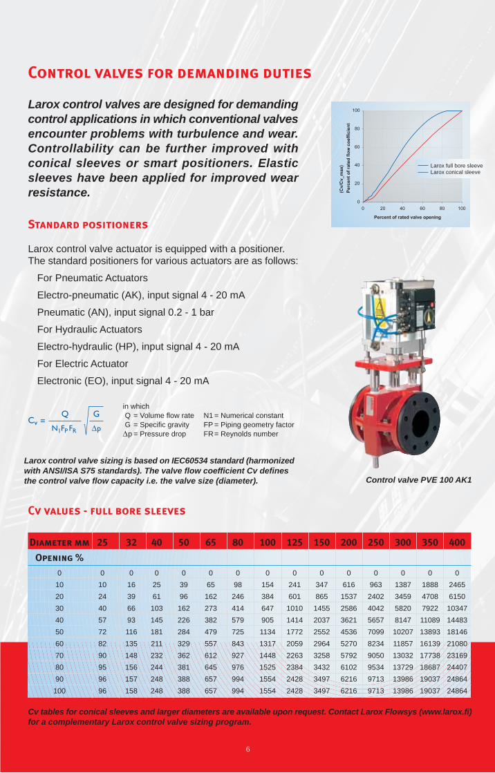
Larox control valves are designed for demandingcontrol applications in which conventional valvesencounter problems with turbulence and wear.Controllability can be further improved withconical sleeves or smart positioners. Elasticsleeves have been applied for improved wearresistance.
Standard positioners
Larox control valve actuator is equipped with a positioner.The standard positioners for various actuators are as follows:
• For Pneumatic Actuators
• Electro-pneumatic (AK), input signal 4 - 20 mA
• Pneumatic (AN), input signal 0.2 - 1 bar
• For Hydraulic Actuators
• Electro-hydraulic (HP), input signal 4 - 20 mA
• For Electric Actuator
• Electronic (EO), input signal 4 - 20 mA
Cv values - full bore sleeves
Diameter mm
Opening %
0
10
20
30
40
50
60
70
80
90
100
25
0
10
24
40
57
72
82
90
95
96
96
40
0
25
61
103
145
181
211
232
244
248
248
50
0
39
96
162
226
284
329
362
381
388
388
65
0
65
162
273
382
479
557
612
645
657
657
80
0
98
246
414
579
725
843
927
976
994
994
100
0
154
384
647
905
1134
1317
1448
1525
1554
1554
32
0
16
39
66
93
116
135
148
156
157
158
125
0
241
601
1010
1414
1772
2059
2263
2384
2428
2428
150
0
347
865
1455
2037
2552
2964
3258
3432
3497
3497
200
0
616
1537
2586
3621
4536
5270
5792
6102
6216
6216
250
0
963
2402
4042
5657
7099
8234
9050
9534
9713
9713
300
0
1387
3459
5820
8147
10207
11857
13032
13729
13986
13986
350
0
1888
4708
7922
11089
13893
16139
17738
18687
19037
19037
400
0
2465
6150
10347
14483
18146
21080
23169
24407
24864
24864
Control valve PVE 100 AK1
CvQ
N1FP FR p
G=
in whichQ = Volume flow rateG = Specific gravityp = Pressure drop
N1 = Numerical constantFP = Piping geometry factorFR= Reynolds number
Control valves for demanding duties
Larox control valve sizing is based on IEC60534 standard (harmonizedwith ANSI/ISA S75 standards). The valve flow coefficient Cv definesthe control valve flow capacity i.e. the valve size (diameter).
Cv tables for conical sleeves and larger diameters are available upon request. Contact Larox Flowsys (www.larox.fi)for a complementary Larox control valve sizing program.
Larox full bore sleeveLarox conical sleeve

7
Main dimensions
Open and enclosed body
Dimensions subject to change without notice. Larger sizes and higher pressures also available.Complete dimensional drawings with selected actuator available upon request.
PV PVE
Size
pv 80
pv 100
pv 125
pv 150
pv 200
pv 250
pv 300
pve 25
pve 32
pve 40
pve 50
pve 65
pve 80
pve 100
pve 125
pve 150
pve 200
pve 250
pve 300
PN (bar)
1 - 25
1 - 25
1 - 25
1 - 16
1 - 16
1 - 10
1 - 6
1 - 25
1 - 25
1 - 25
1 - 25
1 - 25
1 - 25
1 - 25
1 - 25
1 - 16
1 - 16
1 - 10
1 - 6
A (mm)
200
250
310
375
500
625
750
165
165
165
165
165
200
250
310
375
500
625
750
B (mm)
235
265
325
381
461
545
704
125
140
180
190
210
245
278
340
400
480
570
720
E (mm)
100
110
135
143
170
210
250
87
90
105
120
136
155
175
210
240
295
380
445
WEIGHT fe (kg)
14
16
23
36
47
85
100
8
10
12
13
17
27
33
48
75
119
161
212
WEIGHT al (kg)
-
-
-
-
-
-
-
4
5
6
7
9
13
17
25
43
-
-
-
Weights are for body and sleeve without actuatorwithout actuator..

LPP
Pumps
Automatic 03/06 ENG
Larox Flowsys Oy • P.O. Box 338 • FI-53101 Lappeenranta, Finland • Tel. +358 201 113 311 • Fax +358 201 113 300
e-mail [email protected] • www.larox.fi
TYPE APPROVALP-11460
For your local Larox
representative see
www.larox.fi
Valve
Sleeves
The solution you’ve been looking for
Manual
Valves
The solution you’ve been looking for
Automatic
Valves
The solution you’ve been looking for
The solution you’ve been looking forCompany
Profile
Top Related