


Languages
Pages
Legal

www.schneider-electric.com
Altivar 61/71Variable speed drivesfor synchronous and asynchronous motors
EtherCAT® Communication ManualVW3A332604/2013
HR
B14
105
efesotomasyon.com
2 HRB14105 04/2013
The information provided in this documentation contains general descriptions and/or technical characteristics of the performance of the products contained herein. This documentation is not intended as a substitute for and is not to be used for determining suitability or reliability of these products for specific user applications. It is the duty of any such user or integrator to perform the appropriate and complete risk analysis, evaluation and testing of the products with respect to the relevant specific application or use thereof. Neither Schneider Electric nor any of its affiliates or subsidiaries shall be responsible or liable for misuse of the information contained herein. If you have any suggestions for improvements or amendments or have found errors in this publication, please notify us.
No part of this document may be reproduced in any form or by any means, electronic or mechanical, including photocopying, without express written permission of Schneider Electric.
All pertinent state, regional, and local safety regulations must be observed when installing and using this product. For reasons of safety and to help ensure compliance with documented system data, only the manufacturer should perform repairs to components.
When devices are used for applications with technical safety requirements, the relevant instructions must be followed.
Failure to use Schneider Electric software or approved software with our hardware products may result in injury, harm, or improper operating results.
Failure to observe this information can result in injury or equipment damage.
© 2013 Schneider Electric. All rights reserved.
efesotomasyon.com

HRB14105 04/2013 3
Safety Information . . . . . . . . . . . . . . . . . . . . . . . . . . . . . . . . . . . . . . . . . . . . . . . . . . . . 5About the Book. . . . . . . . . . . . . . . . . . . . . . . . . . . . . . . . . . . . . . . . . . . . . . . . . . . . . . . 6
Chapter 1 ATV61/71 EtherCAT Overview. . . . . . . . . . . . . . . . . . . . . . . . . . . . . . . . . . . . . . . . . . . . 9Overview. . . . . . . . . . . . . . . . . . . . . . . . . . . . . . . . . . . . . . . . . . . . . . . . . . . . . . . . . . . . 10Software and protocols supported . . . . . . . . . . . . . . . . . . . . . . . . . . . . . . . . . . . . . . . . 11Communication and Services. . . . . . . . . . . . . . . . . . . . . . . . . . . . . . . . . . . . . . . . . . . . 12Notation rules in this manual . . . . . . . . . . . . . . . . . . . . . . . . . . . . . . . . . . . . . . . . . . . . 13
Chapter 2 Hardware Setup . . . . . . . . . . . . . . . . . . . . . . . . . . . . . . . . . . . . . . . . . . . . . . . . . . . . . . 15Hardware presentation . . . . . . . . . . . . . . . . . . . . . . . . . . . . . . . . . . . . . . . . . . . . . . . . . 16Wiring . . . . . . . . . . . . . . . . . . . . . . . . . . . . . . . . . . . . . . . . . . . . . . . . . . . . . . . . . . . . . . 17
Chapter 3 Configuration . . . . . . . . . . . . . . . . . . . . . . . . . . . . . . . . . . . . . . . . . . . . . . . . . . . . . . . . 19ESI file (EtherCAT Slave Information) . . . . . . . . . . . . . . . . . . . . . . . . . . . . . . . . . . . . . 20Configuring PDO (communication scanner) . . . . . . . . . . . . . . . . . . . . . . . . . . . . . . . . . 21Configuring the Control Channels . . . . . . . . . . . . . . . . . . . . . . . . . . . . . . . . . . . . . . . . 22Configuring Monitor Parameters. . . . . . . . . . . . . . . . . . . . . . . . . . . . . . . . . . . . . . . . . . 23Configuring Communication Interruption Management . . . . . . . . . . . . . . . . . . . . . . . . 24
Chapter 4 Example with TwinCAT® . . . . . . . . . . . . . . . . . . . . . . . . . . . . . . . . . . . . . . . . . . . . . . . . . . . . . . . . . . . .25
Example: Altivar 61/71 with TwinCAT® "PLC - Configuration" . . . . . . . . . . . . . . . . . . . 26Chapter 5 Diagnostics and monitoring . . . . . . . . . . . . . . . . . . . . . . . . . . . . . . . . . . . . . . . . . . . . 37
LED Indicators . . . . . . . . . . . . . . . . . . . . . . . . . . . . . . . . . . . . . . . . . . . . . . . . . . . . . . . 38Communication Diagnostics . . . . . . . . . . . . . . . . . . . . . . . . . . . . . . . . . . . . . . . . . . . . . 40Control-Signal Diagnostics . . . . . . . . . . . . . . . . . . . . . . . . . . . . . . . . . . . . . . . . . . . . . . 42
Chapter 6 Profiles . . . . . . . . . . . . . . . . . . . . . . . . . . . . . . . . . . . . . . . . . . . . . . . . . . . . . . . . . . . . . 45Definition of a Profile . . . . . . . . . . . . . . . . . . . . . . . . . . . . . . . . . . . . . . . . . . . . . . . . . . 46Functional Profiles Supported by the Altivar 61/71. . . . . . . . . . . . . . . . . . . . . . . . . . . . 47
Chapter 7 Detailed Description of Services. . . . . . . . . . . . . . . . . . . . . . . . . . . . . . . . . . . . . . . . . 49EtherCAT State Machine (ESM). . . . . . . . . . . . . . . . . . . . . . . . . . . . . . . . . . . . . . . . . . 50Emergency Object (EMCY) . . . . . . . . . . . . . . . . . . . . . . . . . . . . . . . . . . . . . . . . . . . . . 52
Chapter 8 Object Dictionary . . . . . . . . . . . . . . . . . . . . . . . . . . . . . . . . . . . . . . . . . . . . . . . . . . . . . 55Introduction. . . . . . . . . . . . . . . . . . . . . . . . . . . . . . . . . . . . . . . . . . . . . . . . . . . . . . . . . . 56Communication Profile Area. . . . . . . . . . . . . . . . . . . . . . . . . . . . . . . . . . . . . . . . . . . . . 57RPDO: Receive PDO . . . . . . . . . . . . . . . . . . . . . . . . . . . . . . . . . . . . . . . . . . . . . . . . . . 57TPDO: Transmit PDO. . . . . . . . . . . . . . . . . . . . . . . . . . . . . . . . . . . . . . . . . . . . . . . . . . 57Sync Manager . . . . . . . . . . . . . . . . . . . . . . . . . . . . . . . . . . . . . . . . . . . . . . . . . . . . . . . 58Manufacturer Specific Area . . . . . . . . . . . . . . . . . . . . . . . . . . . . . . . . . . . . . . . . . . . . . 58Application Profile Area . . . . . . . . . . . . . . . . . . . . . . . . . . . . . . . . . . . . . . . . . . . . . . . . 58
Chapter 9 Glossary . . . . . . . . . . . . . . . . . . . . . . . . . . . . . . . . . . . . . . . . . . . . . . . . . . . . . . . . . . . . 59
Table of Contents
efesotomasyon.com

4 HRB14105 04/2013
efesotomasyon.com

HRB14105 04/2013 5
§
Safety Information
Safety Information
Important Information
NOTICERead these instructions carefully, and look at the equipment to become familiar with the device before trying to install, operate, or maintain it. The following special messages may appear throughout this documentation or on the equipment to warn of potential hazards or to call attention to information that clarifies or simplifies a procedure.
PLEASE NOTEThe word "drive" as used in this manual refers to the controller portion of the adjustable speed drive as defined by NEC.
Electrical equipment should be installed, operated, serviced, and maintained only by qualified personnel. No responsibility is assumed by Schneider Electric for any consequences arising out of the use of this product.
© 2012 Schneider Electric. All Rights Reserved.
The addition of this symbol to a Danger or Warning safety label indicates that an electrical hazard exists, which will result in personal injury if the instructions are not followed.
This is the safety alert symbol. It is used to alert you to potential personal injury hazards. Obey all safety messages that follow this symbol to avoid possible injury or death.
DANGERDANGER indicates an imminently hazardous situation, which, if not avoided, will result in death or serious injury.
WARNINGWARNING indicates a potentially hazardous situation, which, if not avoided, can result in death, serious injury or equipment damage.
CAUTIONCAUTION indicates a potentially hazardous situation, which, if not avoided, can result in injury or equipment damage.
NOTICENOTICE is used to address practices not related to physical injury.
efesotomasyon.com

6 HRB14105 04/2013
About the Book
About the Book
Document ScopeThe purpose of this document is to:• show you how to install the EtherCAT module on your Altivar 61/71,• show you how to configure the Altivar 61/71 to use EtherCAT fieldbus.NOTE: Read and understand this document and all related documents (see below) before installing, operating, or maintaining your ATV61/71.
Validity NoteThis documentation is valid for the Altivar 61/71 EtherCAT fieldbus.
Related Documents
You can download the latest versions of these technical publications and other technical information from www.schneider-electric.com.
Product related information
Title of Documentation Reference Number
ATV71 Installation manual 1755843
ATV61 Programming manual 1760649
ATV71 Programming manual 1755855
ATV71 Communication parameters manual 1755861
ATV61/71 CANopen manual 1755865
ATV71 integrated Modbus 1755863
ATV71 Modbus/Uni-Telway card - Modbus protocol 1755875
ATV71 Modbus/Uni-Telway card - Uni-Telway protocol 1755867
ATV71 Modbus Plus 1755869
ATV61/71 Modbus TCP/IP - Ethernet manual 1755879
ATV61 71 Modbus TCP/IP - Daisy Chain Ethernet manual AAV69931
ATV71 DeviceNet 1755877
ATV61 71 CC-Link manual AAV49429
ATV61/71 Ethernet IP AAV68822
ATV61/71 INTERBUS 1755871
ATV61/71 Profibus DP 1755873
ATV61/71 Profibus DPv1 AAV52935
DANGERUNINTENDED EQUIPMENT OPERATION
• Read and understand this manual before installing or operating the drive.• Any changes made to the parameter settings must be performed by qualified personnel.
Failure to follow these instructions will result in death or serious injury.
efesotomasyon.com

About the Book
HRB14105 04/2013 7
(1) For additional information, refer to NEMA ICS 1.1 (latest edition), “Safety Guidelines for the Application, Installation, and Maintenance of Solid State Control” and to NEMA ICS 7.1 (latest edition), “Safety Standards for Construction and Guide for Selection, Installation and Operation of Adjustable-Speed Drive Systems.”
DANGERHAZARD OF ELECTRIC SHOCK, EXPLOSION OR ARC FLASH
• Only appropriately trained persons who are familiar with and understand the contents of this manual and all other pertinent product documentation and who have received safety training to recognize and avoid hazards involved are authorized to work on and with this product system. Installation, adjustment, repair and maintenance must be performed by qualified personnel.
• The system integrator is responsible for compliance with all local and national electrical code requirements as well as all other applicable regulations with respect to grounding of all equipment.
• Many components of the product, including the printed circuit boards, operate with mains voltage. Do not touch. Use only electrically insulated tools.
• Do not touch unshielded components or terminals with voltage present.• Motors can generate voltage when the shaft is rotated. Prior to performing any type of work on the product
system, block the motor shaft to prevent rotation.• AC voltage can couple voltage to unused conductors in the motor cable. Insulate both ends of unused
conductors of the motor cable.• Do not short across the DC bus terminals or the DC bus capacitors or the braking resistor terminals.• Before performing work on the product system:
- Disconnect all power, including external control power that may be present.- Place a "Do Not Turn On" label on all power switches.- Lock all power switches in the open position.- Wait 15 minutes to allow the DC bus capacitors to discharge. The DC bus LED is not an indicator of the
absence of DC bus voltage that can exceed 800 Vdc.Measure the voltage on the DC bus between the DC bus terminals using a properly rated voltmeter to verify that the voltage is <42 Vdc.
- If the DC bus capacitors do not discharge properly, contact your local Schneider Electric representative.• Install and close all covers before applying voltage.
Failure to follow these instructions will result in death or serious injury.
WARNINGDAMAGE DRIVE EQUIPMENT Do not operate or install any drive or drive accessory that appears damaged.
Failure to follow these instructions can result in death, serious injury, or equipment damage.
WARNINGLOSS OF CONTROL
• The designer of any control scheme must- consider the potential failure modes of control paths and, for certain critical control functions, - provide a means to achieve a safe state during and after a path failure.
Examples of critical control functions are emergency stop and overtravel stop.• Separate or redundant control paths must be provided for critical control functions.• System control paths may include communication links. Consideration must be given to the implications
of unanticipated transmission delays or failures of the link.(1)
Failure to follow these instructions can result in death, serious injury, or equipment damage.
efesotomasyon.com

About the Book
8 HRB14105 04/2013
efesotomasyon.com

HRB14105 04/2013 9
ATV61/71 EtherCAT Overview
1ATV61/71 EtherCAT Overview
What's in this Chapter?This chapter contains the following topics:
Topic Page
Overview 10
Software and protocols supported 11
Communication and Services 12
Notation rules in this manual 13
efesotomasyon.com

ATV61/71 EtherCAT Overview
10 HRB14105 04/2013
OverviewThe VW3A3326 communication card enables the integration of an Altivar 61/71 variable speed drive into an EtherCAT network.
efesotomasyon.com

ATV61/71 EtherCAT Overview
HRB14105 04/2013 11
Software and protocols supported
ATV61/71 compatibilityThe VW3A3326 EtherCAT card is compliant with ATV71 minimum version 5.7 and ATV61 minimum version 5.8.
ATV61/71 Profile with EtherCAT®
EtherCAT® is a registered trademark and patented technology licensed by Beckhoff Automation GmbH, Germany. The ATV61/71 supports CANopen CiA®402 V3 drive profile, using CoE (CAN application layer Over EtherCAT).
BECKHOFF® software
The ATV61/71 communication card is compliant with BECKHOFF software TwinCAT® V2.x with CodeSys V2.
Further readingRecommended literature for further readingEtherCAT Technology Group (ETG), see www.ethercat.org
efesotomasyon.com

ATV61/71 EtherCAT Overview
12 HRB14105 04/2013
Communication and Services
Cyclical Communication: PDO• PDO is intended for use with the communication scanner according to CiA402.
• PDO overview
The configuration means are:• EtherCAT configuration tool, then the configuration is downloaded by the master,• SoMove or SoMachine: DTM ATV61/71.
Acyclic Services: SDOThe ATV61/71 manages a SDO server (Service Data Object). SDO telegrams are used for configuration and adjustment, they are characterized by two identifiers:• One for requests (telegrams sent from the PLC to the Altivar)• One for responses (telegrams sent back to the PLC by the Altivar)
Other Supported ServicesAssignment by default of address-based identifiers.• EtherCAT state machine commands• Emergency (EMCY)
ESI file (EtherCAT Slave Information)Download the ESI file in XML format for the ATV61/71 on www.schneider-electric.com.
CMD value LFRD value NC3 NC4 NC5 NC6 NC7 NC8 = RPDO
ETA value RFRD value NM3 NM4 NM5 NM6 NM7 NM8 = TPDO
efesotomasyon.com

ATV61/71 EtherCAT Overview
HRB14105 04/2013 13
Notation rules in this manual
Drive Terminal DisplaysThe graphic display terminal (to be ordered separately - reference VW3A1101) menus are shown in square
brackets.
Example: [COMMUNICATION]The integrated 7-segment display terminal menus are shown in round brackets.
Example: (COM-)
Parameter names are displayed on the graphic display terminal in square brackets.
Example: [Fallback speed]Parameter codes are displayed on the integrated 7-segment display terminal in round brackets.
Example: (LFF)
FormatsIn this manual, hexadecimal values are written as follows: 16#
efesotomasyon.com

ATV61/71 EtherCAT Overview
14 HRB14105 04/2013
efesotomasyon.com

HRB14105 04/2013 15
Hardware Setup
2Hardware Setup
What's in this Chapter?This chapter contains the following topics:
Topic Page
Hardware presentation 16
Wiring 17
efesotomasyon.com

Hardware Setup
16 HRB14105 04/2013
Hardware presentation
Receipt• Check that the card catalog number marked on the label is the same as that on the delivery note
corresponding to the purchase order.• Remove the communication module from its packaging and check that it has not been damaged in transit.
Presentation
InstallationFirst remove the control front panel.
DANGERHAZARD OF ELECTRIC SHOCK, EXPLOSION OR ARC FLASHRead and understand the precautions in the About the book section before performing the procedure in this section.
Failure to follow these instructions will result in death or serious injury.
LEDs
Dual RJ45
NOTICERISK OF DAMAGE TO THE CONNECTOR
Ensure good positioning of the option card on the clasps to avoid damage to the connector.
Failure to follow these instructions can result in equipment damage.
321
Install encoder interface card (if used)
4
Replace the control front panel over the option card (same procedure as for installing the option card, see and )
75 6
65
74
Position the option card on the clasps
Then pivot it until it clicks into place
5
6
efesotomasyon.com
Hardware Setup
HRB14105 04/2013 17
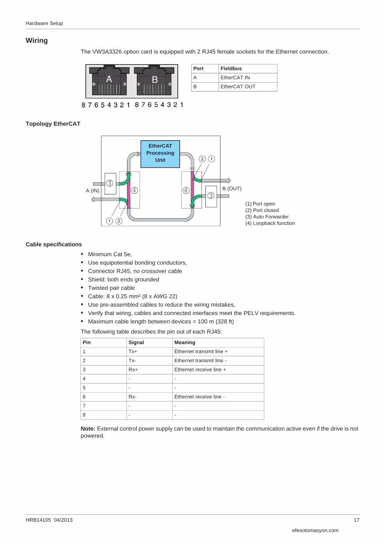
WiringThe VW3A3326 option card is equipped with 2 RJ45 female sockets for the Ethernet connection.
Topology EtherCAT
Cable specifications• Minimum Cat 5e,• Use equipotential bonding conductors,• Connector RJ45, no crossover cable• Shield: both ends grounded• Twisted pair cable• Cable: 8 x 0.25 mm² (8 x AWG 22)• Use pre-assembled cables to reduce the wiring mistakes,• Verify that wiring, cables and connected interfaces meet the PELV requirements.• Maximum cable length between devices = 100 m (328 ft)
The following table describes the pin out of each RJ45:
Note: External control power supply can be used to maintain the communication active even if the drive is not powered.
Port Fieldbus
A EtherCAT IN
B EtherCAT OUT
A (IN) B (OUT)
(1) Port open(2) Port closed(3) Auto Forwarder(4) Loopback function
EtherCATProcessing
Unit
Pin Signal Meaning
1 Tx+ Ethernet transmit line +
2 Tx- Ethernet transmit line -
3 Rx+ Ethernet receive line +
4 - -
5 - -
6 Rx- Ethernet receive line -
7 - -
8 - -
efesotomasyon.com

Hardware Setup
18 HRB14105 04/2013
efesotomasyon.com

HRB14105 04/2013 19
Configuration
3Configuration
What's in this Chapter?This chapter contains the following topics:
Topic Page
ESI file (EtherCAT Slave Information) 20
Configuring the Communication Parameters 20
Configuring Monitor Parameters 23
Configuring Communication Interruption Management 24
efesotomasyon.com
Configuration
20 HRB14105 04/2013
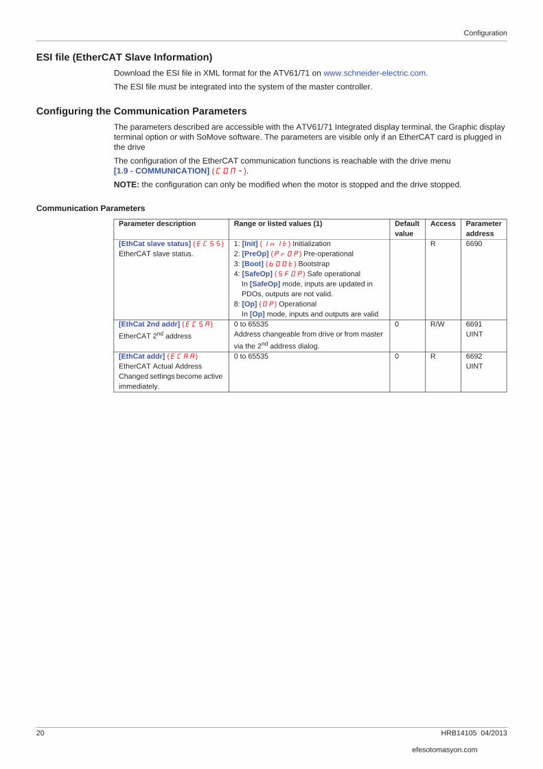
ESI file (EtherCAT Slave Information)Download the ESI file in XML format for the ATV61/71 on www.schneider-electric.com.
The ESI file must be integrated into the system of the master controller.
Configuring the Communication ParametersThe parameters described are accessible with the ATV61/71 Integrated display terminal, the Graphic display terminal option or with SoMove software. The parameters are visible only if an EtherCAT card is plugged in the drive
The configuration of the EtherCAT communication functions is reachable with the drive menu [1.9 - COMMUNICATION] (COM-).
NOTE: the configuration can only be modified when the motor is stopped and the drive stopped.
Communication Parameters
Parameter description Range or listed values (1) Defaultvalue
Access Parameteraddress
[EthCat slave status] (ECSS)EtherCAT slave status.
1: [Init] (InIt) Initialization2: [PreOp] (PrOP) Pre-operational3: [Boot] (bOOt) Bootstrap4: [SafeOp] (SFOP) Safe operational
In [SafeOp] mode, inputs are updated in PDOs, outputs are not valid.
8: [Op] (OP) OperationalIn [Op] mode, inputs and outputs are valid
R 6690
[EthCat 2nd addr] (ECSA)EtherCAT 2nd address
0 to 65535Address changeable from drive or from master via the 2nd address dialog.
0 R/W 6691UINT
[EthCat addr] (ECAA)EtherCAT Actual AddressChanged settings become active immediately.
0 to 65535 0 R 6692UINT
efesotomasyon.com

Configuration
HRB14105 04/2013 21
Configuring PDO (communication scanner)PDOs are configured by configuring the communication scanner.The 8 periodic output variables are assigned by means of parameters nCA1 to nCA8. They are configured using the graphic display terminal via the [1.9 - COMMUNICATION] (COM-) menu and [COM. SCANNER OUTPUT] (OCS-) submenu. Note: [COM. SCANNER OUTPUT] (OCS-) submenu defines the data (parameters nCA1 to nCA8) from the PLC to the drive.An nCAp parameter with a value of zero does not designate any parameter in the drive. These 8 words are described in the table below:
The 8 periodic input variables are assigned by means of parameters nMA1 to nMA8. They are configured using the graphic display terminal via the [1.9 - COMMUNICATION] (COM-) menu and [COM. SCANNER INPUT] (ICS-) submenu.
Note: [COM. SCANNER INPUT] (ICS-) submenu defines the data (parameters nMA1 to nMA8) from the drive to the PLC.
An nMAp parameter with a value of zero does not designate any parameter in the drive. These 8 words are described in the table below:
Example of configuring PDOs via the graphic display terminal:
Note:Modifications to parameters nMA1 ... nMA8 or nCA1 ... nCA8 shall be made with the motor stopped. The master PLC program should be updated to take account of this modification.
Parameter name PDOs variable Default assignment[Scan. Out1 address] (nCA1) RPDO1 Command word (CMD)[Scan. Out2 address] (nCA2) RPDO2 Speed target (LFRD)[Scan. Out3 address] (nCA3) RPDO3 Not used[Scan. Out4 address] (nCA4) RPDO4 Not used[Scan. Out5 address] (nCA5) RPDO5 Not used[Scan. Out6 address] (nCA6) RPDO6 Not used[Scan. Out7 address] (nCA7) RPDO7 Not used[Scan. Out8 address] (nCA8) RPDO8 Not used
Parameter name PDOs variable Default assignment[Scan. In1 address] (nMA1) TPDO1 Status word (ETA)[Scan. In2 address] (nMA2) TPDO2 Output speed (RFRD)[Scan. In3 address] (nMA3) TPDO3 Not used[Scan. In4 address] (nMA4) TPDO4 Not used[Scan. In5 address] (nMA5) TPDO5 Not used[Scan. In6 address] (nMA6) TPDO6 Not used[Scan. In7 address] (nMA7) TPDO7 Not used[Scan. In8 address] (nMA8) TPDO8 Not used
RDY NET +0.00Hz 0A RDY NET +0.00Hz 0A
COM. SCANNER INPUT COM. SCANNER OUTPUT
Scan. In1 address : 3201 Scan. Out1 address : 8501
Scan. In2 address : 8604 Scan. Out2 address : 8602
Scan. In3 address : 0 Scan. Out3 address : 0
Scan. In4 address : 0 Scan. Out4 address : 0
Scan. In5 address : 0 Scan. Out5 address : 0
Code Quick Code Quick
Scan. In6 address : 0 Scan. Out6 address : 0
Scan. In7 address : 0 Scan. Out7 address : 0
Scan. In8 address : 0 Scan. Out8 address : 0
efesotomasyon.com
Configuration
22 HRB14105 04/2013
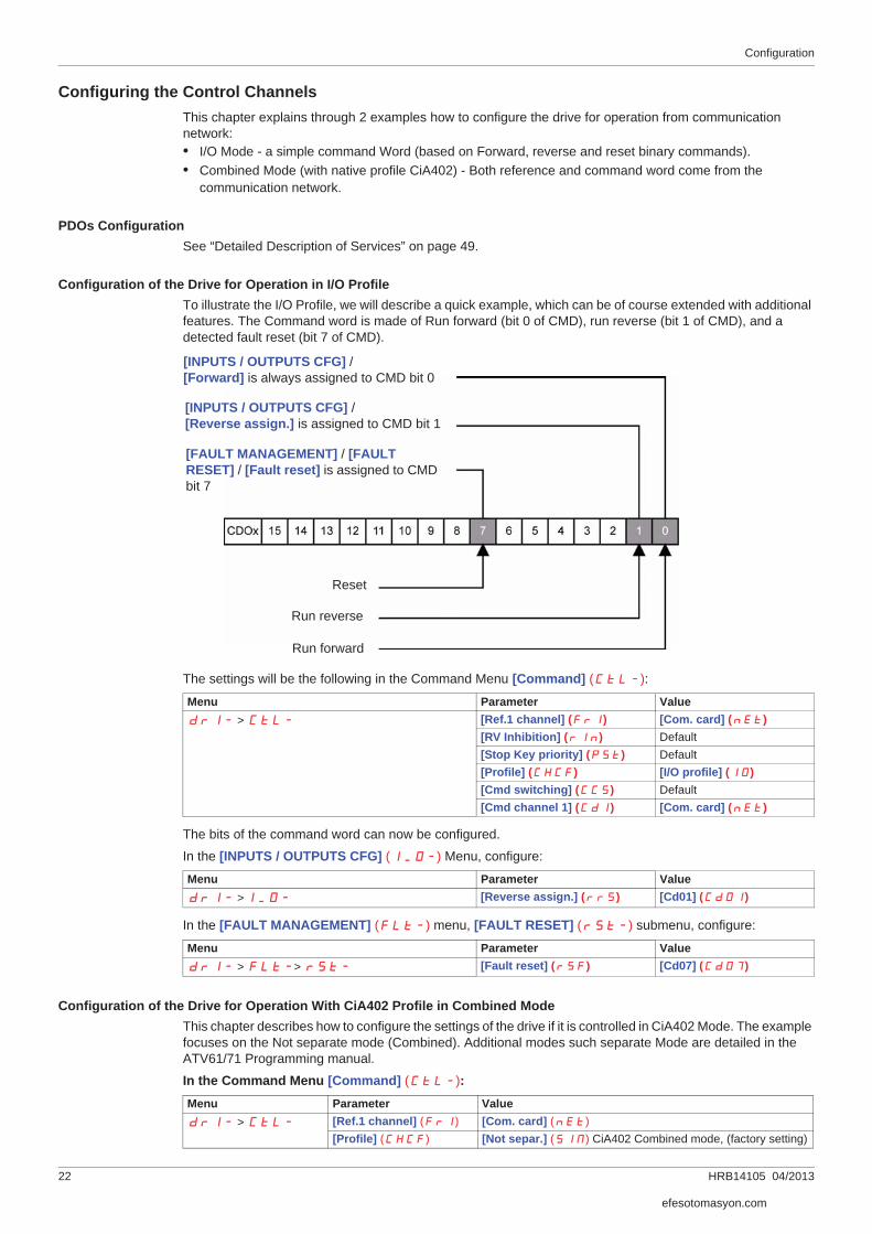
Configuring the Control ChannelsThis chapter explains through 2 examples how to configure the drive for operation from communication network:• I/O Mode - a simple command Word (based on Forward, reverse and reset binary commands).• Combined Mode (with native profile CiA402) - Both reference and command word come from the
communication network.
PDOs Configuration See “Detailed Description of Services” on page 49.
Configuration of the Drive for Operation in I/O ProfileTo illustrate the I/O Profile, we will describe a quick example, which can be of course extended with additional features. The Command word is made of Run forward (bit 0 of CMD), run reverse (bit 1 of CMD), and a detected fault reset (bit 7 of CMD).
The settings will be the following in the Command Menu [Command] (CtL-):
The bits of the command word can now be configured.
In the [INPUTS / OUTPUTS CFG] (I_O-) Menu, configure:
In the [FAULT MANAGEMENT] (FLt-) menu, [FAULT RESET] (rSt-) submenu, configure:
Configuration of the Drive for Operation With CiA402 Profile in Combined ModeThis chapter describes how to configure the settings of the drive if it is controlled in CiA402 Mode. The example focuses on the Not separate mode (Combined). Additional modes such separate Mode are detailed in the ATV61/71 Programming manual.
In the Command Menu [Command] (CtL-):
Menu Parameter ValuedrI- > CtL- [Ref.1 channel] (Fr1) [Com. card] (nEt)
[RV Inhibition] (rIn) Default[Stop Key priority] (PSt) Default[Profile] (CHCF) [I/O profile] (IO)[Cmd switching] (CCS) Default[Cmd channel 1] (Cd1) [Com. card] (nEt)
Menu Parameter ValuedrI- >I_O- [Reverse assign.] (rrS) [Cd01] (Cd01)
Menu Parameter ValuedrI- > FLt-> rSt- [Fault reset] (rSF) [Cd07] (Cd07)
[INPUTS / OUTPUTS CFG] / [Forward] is always assigned to CMD bit 0
[INPUTS / OUTPUTS CFG] / [Reverse assign.] is assigned to CMD bit 1
[FAULT MANAGEMENT] / [FAULT RESET] / [Fault reset] is assigned to CMD bit 7
Reset
Run reverse
Run forward
Menu Parameter ValuedrI- > CtL- [Ref.1 channel] (Fr1) [Com. card] (nEt)
[Profile] (CHCF) [Not separ.] (SIM) CiA402 Combined mode, (factory setting)
efesotomasyon.com

Configuration
HRB14105 04/2013 23
Configuring Monitor ParametersIt is possible to select up to 4 parameters to display their values in the [1.2 MONITORING] menu on the graphic display terminal (to be ordered separately - reference VW3A1101).
The selection is made via the [6 MONITORING CONFIG.] --> [COM. MAP CONFIG.] submenu.
Each parameter in the range [Word 1 add. select.] ... [Word 4 add. select.] can be used to select the parameter logic address. An address at zero is used to disable the function.
ExampleIn the example given here, the monitored words are:• Parameter 1 = [Motor current] (LCr): logic address 3204, signed decimal format.• Parameter 2 = [Motor torque] (Otr): logic address 3205, signed decimal format.• Parameter 3 = [Last fault occured] (LFt): logic address 7121, hexadecimal format.• Disabled parameter: 0; default format: Hexadecimal format
One of the three display formats below can be assigned to each monitored word:
NOTE: If a monitored parameter:• has been assigned to an unknown address,• has been assigned to a protected parameter,• has not been assigned,the value displayed in the [COMMUNICATION MAP] screen is: “••••” (see “Diagnostics and monitoring” on page 37).
RDY CAN +0.00Hz 0A
COM. MAP CONFIG.
Address 1 select : 3204
FORMAT 1 : Signed
Address 2 select : 3205
FORMAT 2 : Signed
Address 3 select : 7121
Code Quick
FORMAT 3 : Hex
Address 4 select : 0
FORMAT 4 : Hex
Format Range Terminal display
Hexadecimal 0000 ... FFFF [Hex]
Signed decimal -32 767 ... 32 767 [Signed]
Unsigned decimal 0 ... 65 535 [Unsigned]
efesotomasyon.com

Configuration
24 HRB14105 04/2013
Configuring Communication Interruption Management
The response of the drive in the event of a communication interruption can be configured.
With the graphic display terminal or the integrated display terminal, select the drive menu:[1.8 FAULT MANAGEMENT] (FLt-) --> [COM. FAULT MANAGEMENT] (CLL-), via the [Network fault mgt] (CLL) parameter.
The values of the [Network fault mgt] (CLL) parameter, which trigger a drive detected fault[Com. network] (CnF), are:
The values of the [Network fault mgt] (CLL) parameter, which do not trigger a drive detected fault, are:
The fallback speed can be configured in the [FAULT MANAGEMENT] (FLt-) / [FALLBACK SPEED] (LFF-) menu using the [Fallback speed] (LFF) parameter.
WARNINGLOSS OF CONTROL If Network fault management [Network fault mgt] (CLL) is set to [Ignore] (nO), communicationcontrol will be inhibited.For safety reasons, inhibiting the communication interruption detection should be restricted to the debugphase or to special applications.
Failure to follow these instructions can result in death, serious injury, or equipment damage.
RDY nEt +0.00Hz 0A
COM. FAULT MANAGEMENT
Network fault mgt : Freewheel
CANopen fault mgt : Freewheel
Modbus fault mgt : Freewheel
Code Quick
Value Meaning
[Freewheel] (YES) Freewheel stop (factory setting)
[Ramp stop] (rMP) Stop on ramp
[Fast stop] (FSt) Fast stop
[DC injection] (dCI) DC injection stop. This type of stop cannot be used with certain other functions. See the Programming manual.
Value Meaning
[Ignore] (nO) Detected fault ignored
[Per STT] (Stt) Stop according to configuration of [Type of stop] (Stt), see the Programming manual for more details.
[fallback speed] (LFF) Change to fallback speed, maintained as long as the detected fault persists and the run command has not been removed
[Spd maint.] (rLS) The drive maintains the speed at the time the detected fault occurred, as long as the detected fault persists and the run command has not been removed
efesotomasyon.com

HRB14105 04/2013 25
Example with TwinCAT®
4Example with TwinCAT®
What's in this Chapter?This chapter contains the following topics:
Topic Page
Example: Altivar 61/71 with TwinCAT® "PLC - Configuration" 26
efesotomasyon.com

Example with TwinCAT®
26 HRB14105 04/2013
Example: Altivar 61/71 with TwinCAT® "PLC - Configuration"
1. HardwareConnect your computer and the ATV61/71 EtherCAT option with a standard Cat 5e minimum cable (2 x RJ45, shielded twisted pair cable)
2. TwinCAT® software installation
Install the TwinCAT® software. Example realized with TwinCAT® software version 2.11.Note: The screenshots or procedure in this example may change with a new TwinCAT® software version.
3. ESI file (EtherCAT Slave Information)Download the ESI file in XML format (Schneider_Electric_ATV71_Vxxx.xml) for the ATV61/71 on www.schneider-electric.com.
Copy this XML file on your computer in C:\TwinCAT\Io\EtherCAT.
Integrate the ESI file into the system of the master controller.
4. Altivar 61/71 configurationRealize the configuration of the Drive for Operation With CiA402 Profile in Combined Mode.
Set [Ref.1 channel] (Fr1) to [Com. card] (nEt),
Set [Profile] (CHCF) to [Not separ.] (SIM) CiA402 Combined mode, (factory setting).
5. System Manager: Declare your computer on Ethernet network
Start TwinCAT® system-manager®
Select Option --> "Show Real Time Ethernet Compatible devices"
Select your Computer Ethernet board, and "Install".
Enable it.
�
�
efesotomasyon.com
Example with TwinCAT®
HRB14105 04/2013 27
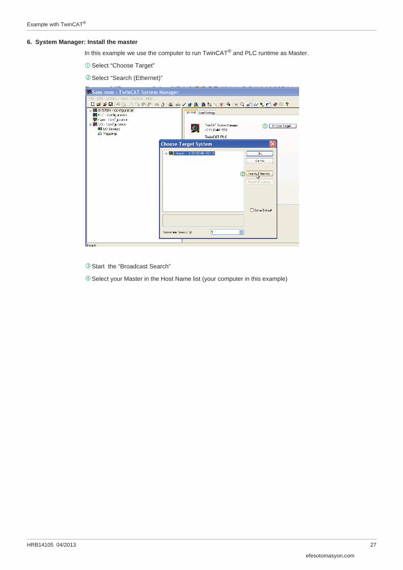
6. System Manager: Install the master
In this example we use the computer to run TwinCAT® and PLC runtime as Master.
Select “Choose Target”
Select “Search (Ethernet)”
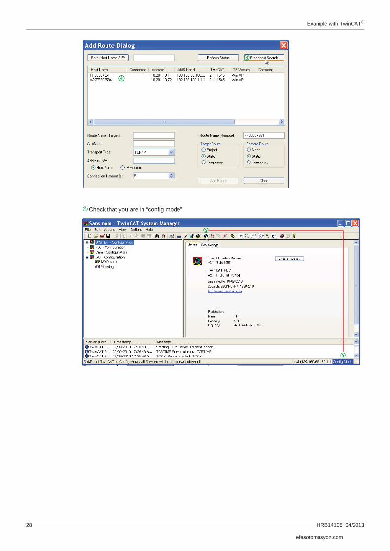
Start the “Broadcast Search”
Select your Master in the Host Name list (your computer in this example)
�
�
�
�
efesotomasyon.com
Example with TwinCAT®
28 HRB14105 04/2013
Check that you are in “config mode”�
efesotomasyon.com

Example with TwinCAT®
HRB14105 04/2013 29
7. System Manager - Install the slave: Altivar 61/71 in "PLC – Configuration"
8. PLC – Control: initialization
Start TwinCAT PLC control® software
File -> new
�
�
�
�
ATV71 created
�
�
ST: Structured language
efesotomasyon.com
Example with TwinCAT®
30 HRB14105 04/2013
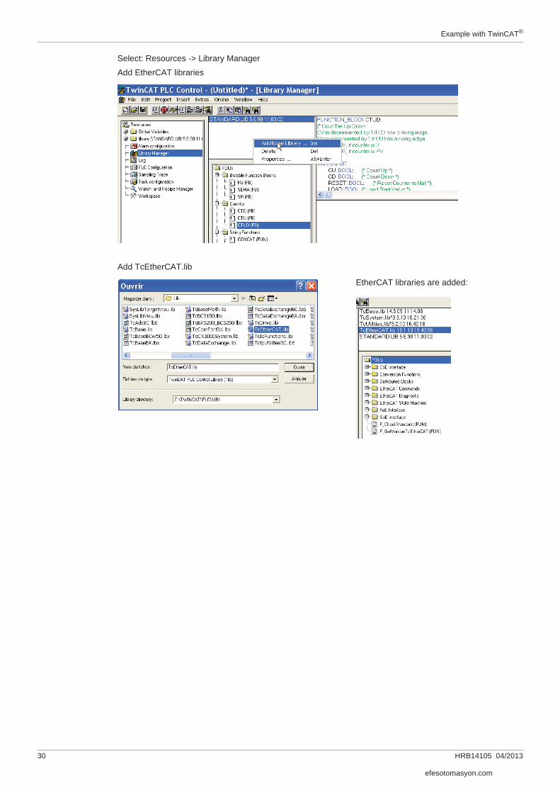
Select: Resources -> Library Manager
Add EtherCAT libraries
Add TcEtherCAT.lib
EtherCAT libraries are added:
efesotomasyon.com

Example with TwinCAT®
HRB14105 04/2013 31
9. PLC - Control: Declare the variables Select Global_Variables
Create the Master Global_Variables for ATV61/71 as below. Copy/paste the variables:VAR_GLOBAL
ATV71_State AT %I*:WORD; PLC_state AT %I*:UINT; ATV71_TPDO_Input1_Status_Word AT %I*:WORD; ATV71_TPDO_Input2_Control_Effort AT %I*:WORD; ATV71_TPDO_Input3 AT %I*:WORD; ATV71_TPDO_Input4 AT %I*:WORD; ATV71_TPDO_Input5 AT %I*:WORD; ATV71_TPDO_Input6 AT %I*:WORD; ATV71_TPDO_Input7 AT %I*:WORD; ATV71_TPDO_Input8 AT %I*:WORD; ATV71_RPDO_Output1_Control_Word AT %Q*:WORD; ATV71_RPDO_Output2_Target_Velocity AT %Q*:WORD; ATV71_RPDO_Output3 AT %Q*:WORD; ATV71_RPDO_Output4 AT %Q*:WORD; ATV71_RPDO_Output5 AT %Q*:WORD; ATV71_RPDO_Output6 AT %Q*:WORD; ATV71_RPDO_Output7 AT %Q*:WORD; ATV71_RPDO_Output8 AT %Q*:WORD;END_VAR
Reminder:
• RPDO (Receive PDO), containing 8 input words of the communication scanner NCA1 to NCA8.• TPDO (Transmit PDO), containing 8 output words of the communication scanner NMA1 to NMA8.
Add 1 instruction minimum in POUs before rebuild;
• Select: Project -> Rebuild All• Check the compilation result without error.• This action creates files in: C:\TwinCAT\Plc\
As example, create: ATV71_PLC.tpy
efesotomasyon.com

Example with TwinCAT®
32 HRB14105 04/2013
10. System Manager - Append PLC ProjectIn System Manager software, realize the link between the Master and the slave. Creation of the links between "PLC - Configuration" and "I/O - Configuration"
Select "Append PLC Project…":
As example, select: C:\TwinCAT\Plc\ATV71_PLC.tpy
For each parameter, create the link with the ATV71 I/O listing
Example for "ATV71_State"
efesotomasyon.com

Example with TwinCAT®
HRB14105 04/2013 33
Links to create
Note: if more than 8 input or output parameters are created in TwinCAT® System Manager, the ATV61/71 will be blocked in "PreOp" state. The ATV61/71 has maximum 8 TPDO and 8 RPDO.
Select: Actions -> Generate Mappings.
11. PLC - Control: new compilationSelect: Project -> Rebuild All
This action updates the information. At this step, if the TwinCAT_Configuration (VAR_CONFIG) is not in the Global Variables, the information will not be updated, and the link will not be built.
12. System Manager: Activate configurationSelect: Actions -> Activate Configurations
13. PLC - Control: new compilationSelect: Online -> login
Select: Online -> Run
The PLC and the EtherCAT fieldbus are now running
In TwinCAT® PLC Control, you see the list of the variables and values:
PLC - Configuration I/O - ConfigurationInputs ATV71_State StateInputs PLC_state DevState (with Device1)Inputs ATV71_TPDO_Input1_Status_Word Status wordInputs ATV71_TPDO_Input2_Control_Effort Control effortInputs ATV71_TPDO_Input3 Available for other parameterInputs ATV71_TPDO_Input4 Available for other parameterInputs ATV71_TPDO_Input5 Available for other parameterInputs ATV71_TPDO_Input6 Available for other parameterInputs ATV71_TPDO_Input7 Available for other parameterInputs ATV71_TPDO_Input8 Available for other parameterOutputs ATV71_RPDO_Output1_Control_Word Control wordOutputs ATV71_RPDO_Output2_Target_Velocity Target VelocityOutputs ATV71_RPDO_Output3 Available for other parameterOutputs ATV71_RPDO_Output4 Available for other parameterOutputs ATV71_RPDO_Output5 Available for other parameterOutputs ATV71_RPDO_Output6 Available for other parameterOutputs ATV71_RPDO_Output7 Available for other parameterOutputs ATV71_RPDO_Output8 Available for other parameter
efesotomasyon.com
Example with TwinCAT®
34 HRB14105 04/2013
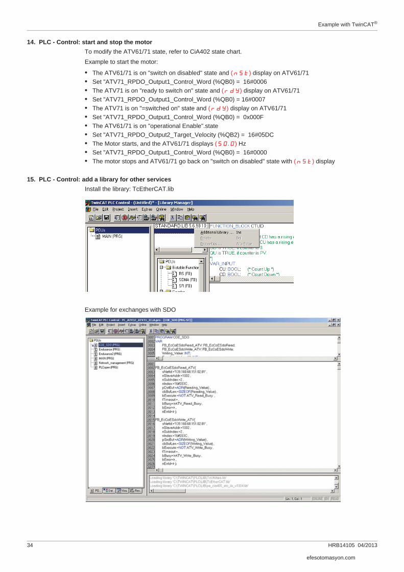
14. PLC - Control: start and stop the motorTo modify the ATV61/71 state, refer to CiA402 state chart.
Example to start the motor:
• The ATV61/71 is on "switch on disabled" state and (nSt) display on ATV61/71• Set "ATV71_RPDO_Output1_Control_Word (%QB0) = 16#0006• The ATV71 is on "ready to switch on" state and (rdY) display on ATV61/71• Set "ATV71_RPDO_Output1_Control_Word (%QB0) = 16#0007• The ATV71 is on "=switched on" state and (rdY) display on ATV61/71• Set "ATV71_RPDO_Output1_Control_Word (%QB0) = 0x000F• The ATV61/71 is on "operational Enable".state• Set "ATV71_RPDO_Output2_Target_Velocity (%QB2) = 16#05DC• The Motor starts, and the ATV61/71 displays (50.0) Hz• Set "ATV71_RPDO_Output1_Control_Word (%QB0) = 16#0000• The motor stops and ATV61/71 go back on "switch on disabled" state with (nSt) display
15. PLC - Control: add a library for other servicesInstall the library: TcEtherCAT.lib
Example for exchanges with SDO
efesotomasyon.com

Example with TwinCAT®
HRB14105 04/2013 35
Example for exchanges with ESM states
efesotomasyon.com

Example with TwinCAT®
36 HRB14105 04/2013
efesotomasyon.com
HRB14105 04/2013 37
Diagnostics and monitoring
5Diagnostics and monitoring
What's in this Chapter?This chapter contains the following topics:
Topic Page
LED Indicators 38
Communication Diagnostics 40
Control-Signal Diagnostics 42
efesotomasyon.com

Diagnostics and monitoring
38 HRB14105 04/2013
LED IndicatorsThe following figure describes the LEDs status module:
LEDs 2.1 and 2.2: Link / ActivityThese LEDs indicate the status of the EtherCAT port A (IN) and EtherCAT port B (OUT)
LED 2.3: RUN Status
LED 2.4: Network ERRor Status
1.11.21.31.41.5
2.12.22.32.42.5
LED Description
2.1: IN Link/Activity (IN)
2.2: OUT Link/Activity (OUT)
2.3: RUN Network RUN
2.4: ERR Network ERRor status
Color & Status Description
OFF No link
Green ON Link, no activity
Green Flickering Link, activity
Color & Status Description
OFF EtherCAT state: INIT
Green blinking EtherCAT state: PRE-OPERATIONAL
Green single flashing EtherCAT state: SAFE-OPERATIONAL.
Green ON EtherCAT state: OPERATIONAL
Color & Status Description
OFF No detected fault
Red blinking Invalid configuration
Red single flashing Local error (such as synchronization error)
Red double flashing Watchdog timeout
efesotomasyon.com

Diagnostics and monitoring
HRB14105 04/2013 39
LED Behavior Detail
on
off50 ms
200 mson
off
200 mson
off
1000 ms
200 mson
off
200 ms 200 ms 1000 ms
200 ms
Flickering
Blinking
Single flash
Double flash
efesotomasyon.com

Diagnostics and monitoring
40 HRB14105 04/2013
Communication DiagnosticsA properly operating fieldbus is essential for evaluating operating and detected faults messages.
Connections for Fieldbus ModeIf the product cannot be addressed via the fieldbus, first check the connections. The product manual contains the technical data of the device and information on network and device installation. Check the following:• 24Vdc power supply (if used)• Power connections to the device• Fieldbus cable and fieldbus wiring• Network connection to the device
Command and Reference ChannelsDrive's command and reference parameters are managed on a channel-by-channel basis.
It is possible to identify the last value written for each channel and each command or reference parameter:
Monitoring of Communication ChannelsCommunication channels are monitored if they are involved in one of the following parameters:• The control word ([Cmd value] (CMd)) from the active command channel• The control word containing the command switch (bit configured on [Cmd switching] (CCS))• The control word containing the switch for reference 1'1B (bit configured on [Ref 1B switching] (rCb))• The control word containing the switch for reference 1'2 (bit configured on [Ref. 2 switching] (rFC))• The frequency or speed reference ([HMI Frequency ref.] (LFr) or [Nominal speed value] (LFrd))
from the active reference channel• Summing frequency or speed reference ([HMI Frequency ref.] (LFr) or [Nominal speed value]
(LFrd)) 2 (assigned to [Summing ref. 2] (SA2))• Summing frequency or speed reference ([HMI Frequency ref.] (LFr) or [Nominal speed value]
(LFrd)) 3 (assigned to [Summing ref. 3] (SA3))• Subtracting frequency or speed reference ([HMI Frequency ref.] (LFr) or [Nominal speed value]
(LFrd)) 2 (assigned to [Subtract ref. 2] (dA2))• Subtracting frequency or speed reference ([HMI Frequency ref.] (LFr) or [Nominal speed value]
(LFrd)) 3 (assigned to [Subtract ref. 3] (dA3))• The PID regulator reference [HMI PID reference] (PISP)• The PID regulator feedback ([AI Virtual 2] (AIU2))• The reference multiplication coefficient ([Multiplying coeff.] (MFr)) 2 (assigned to
[Multiplier ref. 2] (MA2))• The reference multiplication coefficient ([Multiplying coeff.] (MFr)) 3 (assigned to
[Multiplier ref. 3] (MA3))
As soon as one of these parameters has been written once to a communication channel, it activates monitoring for that channel.
If a communication alarm is sent (in accordance with the protocol criteria) by a monitored port or network card, the drive will trigger a communication interruption.
The drive reacts according to the communication interruption configuration (detected fault, maintenance, fallback, etc.)
If a communication alarm occurs on a channel that is not being monitored, the drive will not trigger a communication interruption.
Parameter name Parameter code
Taken into account bythe drive
Modbus CANopen Communic.card
PLCcard
Control word (CMd) (CMd1) (CMd2) (CMd3) (CMd4)
Extended control word (CMI) (CMI1) (CMI2) (CMI3) (CMI4)
Speed reference (rpm) (LFrd) (LFrd1) (LFrd2) (LFrd3) (LFrd4)
Frequency reference (0.1 Hz) (LFr) (LFr1) (LFr2) (LFr3) (LFr4)
PI regulator reference (PISP) (PIr1) (PIr2) (PIr3) (PIr4)
Analog multiplier reference (MFr) (MFr1) (MFr2) (MFr3) (MFr4)
efesotomasyon.com

Diagnostics and monitoring
HRB14105 04/2013 41
Communication InterruptionsCommunication interruptions are displayed by [Past fault 1] (dP1) indicator of the integrated display terminal or graphic display terminal or by Emergency object (EMCY), described in Emergency Object (EMCY), page 52.
In factory settings, an EtherCAT communication interruption triggers a drive detected fault that can be cleared [Network fault mgt] (CLL) and a freewheel stop.
The response of the drive in the event of an EtherCAT communication interruption can be changed:• Drive fault [Network fault mgt] (CLL) (freewheel stop, stop on ramp, fast stop or DC injection stop).• No drive detected fault (stop, maintain, fallback).
In the event of a [Network fault mgt] (CLL), the drive sends an EMCY message to the EtherCAT master, see Emergency Object (EMCY), page 52.
Communication detected Faults: CnF and ILFAfter a detected fault occurred, here are the values to read:
EtherCAT state machineFor the status, see [EthCAT slave status] (ECSS) page 20.
For the EtherCAT state machine diagram, see page 50.
Enabling of Communication ChannelsA communication channel is enabled once all the parameters involved have been written at least one time.The drive is only able to start if all channels involved in command and reference are enabled. Example:A drive in DSP402 profile is connected to an active communication channel.It is mandatory to write at least one time the reference and the command in order to switch from “4-Switched on” to “5-Operation enabled” stateA communication channel is disabled:• In the event of a communication alarm• In “forced local” mode.
Note: On exiting “forced local” mode:• The drive copies the run commands, the direction and the forced local reference to the active channel
(maintained).• Monitoring of the active command and reference channels resumes following a time delay
[Time-out forc. local] (FLOt).• Drive control only takes effect once the drive has received the reference and the command from the active
channel.
Parameter Description Possible values and descriptions[Option int link](ILF)
This parameter indicates a detected error and can be cleared: It needs a drive Power Off / Power On.
18: Interface connection timeout19: EEPROM/NVS detected fault21: ’No memory' or 'background watchdog' detected fault[Internal link fault 1]
(ILF1)displays the trip that occurred on option card no. 1 (directly mounted on the drive)
[Internal link fault 2] (ILF2)
displays the trip that occurred on option card no. 2
[Com. network](CnF)The parameter [Com. network] (CnF) is displayed on the display terminal (graphic only): [1.10 DIAGNOSTICS] (dGt-) menu, [MORE FAULT INFO] (AFI-) submenu.
This parameter indicates that a network interruption occurred. A value is recorded depending of the interruption type.When the detected fault has disappeared, the option writes 0: No network interruption.Note: (CnF) is available only in "operational" state and if the motor is running.
0: No network interruption1: Unspecified interruption11: lost of link (2ports)23: invalid Sync Manager configuration25: No valid outputs27: Sync Manager watchdog (1port)29: invalid Sync Manager out configuration30: invalid Sync Manager in configuration 31: invalid watchdog configuration36: invalid input mapping37: invalid output mapping38: inconsistent settings43: No valid inputs and outputs44: Sync error80: EE no access81: EE error96: Invalid State machine change
efesotomasyon.com

Diagnostics and monitoring
42 HRB14105 04/2013
Control-Signal DiagnosticsOn the terminal, the [1.2 - MONITORING] (MOn-) menu ([COMMUNICATION MAP] (CMM-) submenu) can be used to display control-signal diagnostic information between the Altivar drive and the EtherCAT master:• Active command channel [Command channel] (CMdC)• Value of the control word (CMD) from the active command channel [Cmd value] (CMd)• Active target channel [Active ref. channel] (rFCC)• Value of the target from the active target channel [Frequency ref.] (FrH)• Value of the status word [ETA state word] (EtA)• Values of the four parameters selected by the user (W---)• The [COM. SCANNER INPUT MAP] submenu: contains the parameter value mapped DRIVE scanner
(NMAx).• The [COM SCAN OUTPUT MAP] submenu: contains the parameter value mapped DRIVE scanner
(NCAx).• In the [CMD. WORD IMAGE] submenu: control words from all channels• In the [FREQ. REF. WORD MAP] submenu: frequency targets produced by all channels
ExampleExample of the display of communication diagnostic information:
Control Word DisplayThe [Command Channel] (CMdC) parameter indicates the active command channel.
The [Cmd value] (CMd) parameter indicates the hexadecimal value of the control word (CMD) used to control the drive.
The [CMD. WORD IMAGE] (CI-) submenu ([CANopen cmd.] (CMd3) parameter) is used to display the hexadecimal value of the control word sent by CANopen.
Frequency Target DisplayThe [Active ref. channel] (rFCC) parameter indicates the active target channel.
The [Frequency ref] parameter indicates the value (in 0.1 Hz units) of the frequency target (LFR) used to control the drive.
The [FREQ. REF. WORD MAP] submenu ([COM. card cmd] parameter) is used to display the value (in 0.1 Hz units) of the speed target sent by the network.
RUN nEt +50.00Hz 80A
COMMUNICATION MAP
Command Channel : Com.Card
Cmd value : 000FHex
Active ref. channel : Com.Card
Frequency ref. : 500.0Hz
ETA state word : 8627Hex
Code Quick
W3204 : 73
W3205 : 725
W7132 : 0000Hex
W0 : -----
COM. SCANNER INPUT MAP
COM SCAN OUTPUT MAP
CMD. WORD IMAGE
FREQ. REF. WORD MAP
MODBUS NETWORK DIAG
MODBUS HMI DIAG
efesotomasyon.com

Diagnostics and monitoring
HRB14105 04/2013 43
Status Word DisplayThe [ETA state word] (EtA) parameter gives the value of the status word (ETA).
Display of the Parameters Selected by the UserThe four [W•••] parameters give the value of the four monitored words selected by the user.
The address and display format of these parameters can be configured in the [3.3 MONITORING CONFIG.] (MCF-) menu ([COM. MAP CONFIG.] (AdL-) submenu).
The value of a monitored word equals “••••” if:• Monitoring has not been activated (address equals W0),• The parameter is protected,• The parameter is not known (example: W3200).
efesotomasyon.com

Diagnostics and monitoring
44 HRB14105 04/2013
efesotomasyon.com
HRB14105 04/2013 45
Profiles
6Profiles
What's in this Chapter?This chapter contains the following topics:
Topic Page
Definition of a Profile 46
Functional Profiles Supported by the Altivar 61/71 47
efesotomasyon.com

Profiles
46 HRB14105 04/2013
Definition of a ProfileThere are three types of profile:• Communication profiles• Functional profiles• Application profiles
Communication ProfilesA communication profile describes the characteristics of the bus or network:• Cables• Connectors• Electrical characteristics• Access protocol• Addressing system• Periodic exchange service• Messaging service• ...
A communication profile is unique to a type of network (Modbus TCP, Profibus DP, etc.) and is used by various different types of device.
Functional ProfilesA functional profile describes the behavior of a type of device. It defines:• Functions• Parameters (name, format, unit, type, etc.)• Periodic I/O variables• State chart(s)• ...
A functional profile is common to all members of a device family (variable speed drives, encoders, I/O modules, displays, etc.).
They can feature common or similar parts. The standardized (IEC 61800-7) functional profiles of variable speed drives are:• CiA402• PROFIDRIVE• CIP
DRIVECOM has been available since 1991.
CiA402 “Device profile for drives and motion control” represents the next stage of this standard’s development and is now part of the IEC 61800-7 standard.
Some protocols also support the ODVA (Open DeviceNet Vendor Association) profile.
Application ProfilesApplication profiles define in their entirety the services to be provided by the devices on a machine. For example, “CiA DSP 417-2 V 1.01 part 2: CANopen application profile for lift control systems - virtual device definitions”.
InterchangeabilityThe aim of communication and functional profiles is to achieve interchangeability of the devices connected via the network.
efesotomasyon.com
Profiles
HRB14105 04/2013 47
Functional Profiles Supported by the Altivar 61/71
I/O ProfileUsing the I/O profile simplifies PLC programming.
The I/O profile mirrors the use of the terminal strip for control by utilizing 1 bit to control a function.
With an Altivar 61/71, the I/O profile can also be used when controlling via a network.
The drive starts up as soon as the run command is sent.
15 bits of the control word (bits 1 to 15) can be assigned to a specific function.
This profile can be developed for simultaneous control of the drive via:• The terminals• The Modbus control word• The CANopen control word• The network module control word
The I/O profile is supported by the drive itself and therefore in turn by all the communication ports (integrated Modbus, CANopen, Ethernet, Profibus DP, DeviceNet, EtherCAT communication modules).
CiA402 ProfileThe drive only starts up following a command sequence.
The control word is standardized.
5 bits of the control word (bits 11 to 15) can be assigned to a function.
The CiA402 profile is supported by the drive itself and therefore in turn by all the communication ports (integrated Modbus, CANopen, Ethernet, Profibus DP, DeviceNet, EtherCAT communication modules).
The Altivar 61/71 supports the CiA402 profile’s “Velocity mode”.
In the CiA402 profile, there are two modes that are specific to the Altivar 61/71 and characterize command and reference management:• Separate mode [Separate] (SEP)• Not separate mode [Not separ.] (SIM)
efesotomasyon.com

Profiles
48 HRB14105 04/2013
efesotomasyon.com
HRB14105 04/2013 49
Detailed Description of Services
8Detailed Description of Services
What's in this Chapter?This chapter contains the following topics:
Topic Page
EtherCAT State Machine (ESM) 50
Emergency Object (EMCY) 52
efesotomasyon.com

Detailed Description of Services
50 HRB14105 04/2013
EtherCAT State Machine (ESM)
ESM DiagramThe EtherCAT State machine coordinates the master and slave applications at start up and during operation. State changes are typically initiated by requests of the master. They are acknowledged by the local application after the associated operations have been executed.
Description of the states management
ESM statesThe state Init defines the foundation of the communication relationship between the master and the slaves at the application layer. Direct communication between the master and the slave is impossible at the application layer. The master uses the Init state to initialize a set of configuration registers of the EtherCAT slave controllers. If the slaves support mailbox services, the Sync Manager is also configured in this state.
In the Pre-Operational state, the mailbox is active. Both master and slave use the mailbox and the corresponding protocol to interchange application-specific initialization data and parameters. In this state, process data communication is not possible.
If the drive does not receive a valid mapping for the process data from the EtherCAT master, it remains in this state.
In the Safe-Operational state, the slave application provides current input data such as limit switch data. Output data of the master are ignored in this state. This state is not a safety function.
In the state Operational, the slave applications deliver current input data and the drive processes the current output data from the drive, such as speed setpoint.
Init
Pre-Operational
Safe-Operational
Operational
OI
IPPI SI
OP PS SP
OSSO
efesotomasyon.com
Detailed Description of Services
HRB14105 04/2013 51
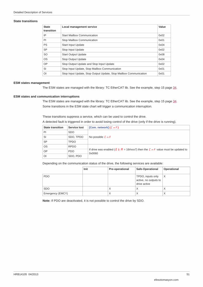
State transitions
ESM states managementThe ESM states are managed with the library: TC EtherCAT lib. See the example, step 15 page 34.
ESM states and communication interruptionsThe ESM states are managed with the library: TC EtherCAT lib. See the example, step 15 page 34.
Some transitions in the ESM state chart will trigger a communication interruption.
These transitions suppress a service, which can be used to control the drive.
A detected fault is triggered in order to avoid losing control of the drive (only if the drive is running).
Depending on the communication status of the drive, the following services are available:
Note: If PDO are deactivated, it is not possible to control the drive by SDO.
Statetransition
Local management service Value
IP Start Mailbox Communication 0x02
PI Stop Mailbox Communication 0x01
PS Start Input Update 0x04
SP Stop Input Update 0x02
SO Start Output Update 0x08
OS Stop Output Update 0x04
OP Stop Output Update and Stop Input Update 0x02
SI Stop Input Update, Stop Mailbox Communication 0x01
OI Stop Input Update, Stop Output Update, Stop Mailbox Communication 0x01
State transition Service lost [Com. network] (CnF)
PI SDO
No possible CnFSI SDO, TPDO
SP TPDO
OS RPDOIf drive was enabled (EtA = 16#xxx7) then the CnF value must be updated to 0x0060
OP PDO
OI SDO, PDO
Init Pre-operational Safe-Operational Operational
PDO TPDO, inputs only active, no outputs to drive active
X
SDO X X X
Emergency (EMCY) X X X
efesotomasyon.com
Detailed Description of Services
52 HRB14105 04/2013
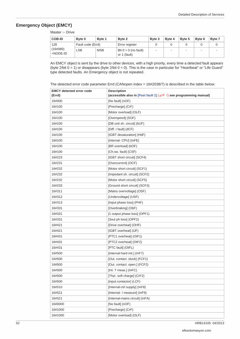
Emergency Object (EMCY)Master B Drive
An EMCY object is sent by the drive to other devices, with a high priority, every time a detected fault appears (byte 2/bit 0 = 1) or disappears (byte 2/bit 0 = 0). This is the case in particular for “Heartbeat” or “Life Guard” type detected faults. An Emergency object is not repeated.
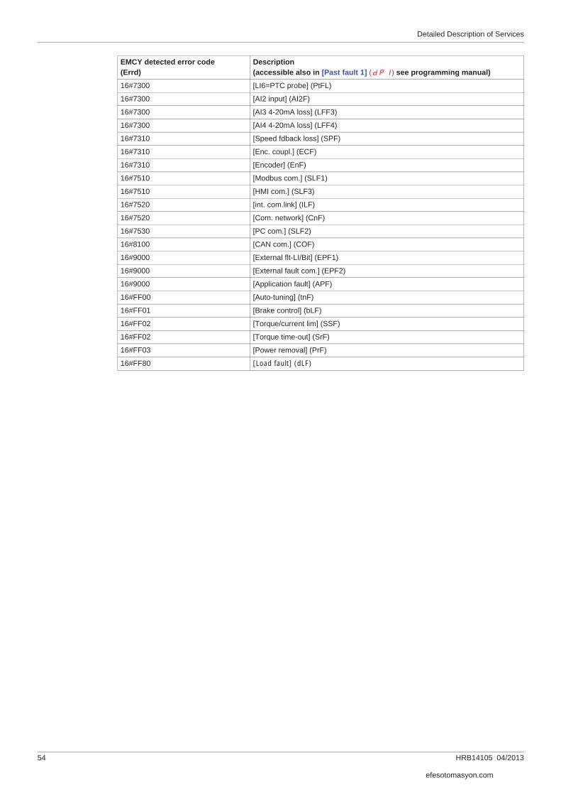
The detected error code parameter Errd (CANopen index = 16#2038/7) is described in the table below:
COB-ID Byte 0 Byte 1 Byte 2 Byte 3 Byte 4 Byte 5 Byte 6 Byte 7
128(16#080)+NODE-ID
Fault code (Errd) Error register 0 0 0 0 0
LSB MSB Bit 0 = 0 (no fault)or 1 (fault)
- - - - -
EMCY detected error code(Errd)
Description (accessible also in [Past fault 1] (dP1) see programming manual)
16#000 [No fault] (nOF)
16#100 [Precharge] (CrF)
16#100 [Motor overload] (OLF)
16#100 [Overspeed] (SOF)
16#100 [DB unit sh. circuit] (bUF)
16#100 [Diff. I fault] (dCF)
16#100 [IGBT desaturation] (HdF)
16#100 [internal- CPU] (InFE)
16#100 [BR overload] (bOF)
16#100 [Ch.sw. fault] (CSF)
16#223 [IGBT short circuit] (SCF4)
16#231 [Overcurrent] (OCF)
16#232 [Motor short circuit] (SCF1)
16#232 [Impedant sh. circuit] (SCF2)
16#232 [Motor short circuit] (SCF5)
16#233 [Ground short circuit] (SCF3)
16#311 [Mains overvoltage] (OSF)
16#312 [Undervoltage] (USF)
16#313 [Input phase loss] (PHF)
16#331 [Overbraking] (ObF)
16#331 [1 output phase loss] (OPF1)
16#331 [3out ph loss] (OPF2)
16#421 [Drive overheat] (OHF)
16#421 [IGBT overheat] (tJF)
16#431 [PTC1 overheat] (OtF1)
16#431 [PTC2 overheat] (OtF2)
16#431 [PTC fault] (OtFL)
16#500 [Internal-hard init.] (InF7)
16#500 [Out. contact. stuck] (FCF1)
16#500 [Out. contact. open.] (FCF2)
16#500 [Int. T meas.] (InFC)
16#500 [Thyr. soft charge] (CrF2)
16#500 [input contactor] (LCF)
16#510 [Internal-ctrl supply] (InF8)
16#521 [Internal- I measure] (InF9)
16#521 [Internal-mains circuit] (InFA)
16#0000 [No fault] (nOF)
16#1000 [Precharge] (CrF)
16#1000 [Motor overload] (OLF)
efesotomasyon.com

Detailed Description of Services
HRB14105 04/2013 53
16#1000 [Overspeed] (SOF)
16#1000 [DB unit sh. circuit] (bUF)
16#1000 [Diff. I fault] (dCF)
16#1000 [IGBT desaturation] (HdF)
16#1000 [internal- CPU] (InFE)
16#1000 [BR overload] (bOF)
16#1000 [Ch.sw. fault] (CSF)
16#2230 [IGBT short circuit] (SCF4)
16#2310 [Overcurrent] (OCF)
16#2320 [Motor short circuit] (SCF1)
16#2320 [Impedant sh. circuit] (SCF2)
16#2320 [Motor short circuit] (SCF5)
16#2330 [Ground short circuit] (SCF3)
16#3110 [Mains overvoltage] (OSF)
16#3120 [Undervoltage] (USF)
16#3130 [Input phase loss] (PHF)
16#3310 [Overbraking] (ObF)
16#3310 [1 output phase loss] (OPF1)
16#3310 [3out ph loss] (OPF2)
16#4210 [Drive overheat] (OHF)
16#4210 [IGBT overheat] (tJF)
16#4310 [PTC1 overheat] (OtF1)
16#4310 [PTC2 overheat] (OtF2)
16#4310 [PTC fault] (OtFL)
16#5000 [Internal-hard init.] (InF7)
16#5000 [Out. contact. stuck] (FCF1)
16#5000 [Out. contact. open.] (FCF2)
16#5000 [Int. T meas.] (InFC)
16#5000 [Thyr. soft charge] (CrF2)
16#5000 [input contactor] (LCF)
16#5100 [Internal-ctrl supply] (InF8)
16#5210 [Internal- I measure] (InF9)
16#5210 [Internal-mains circuit] (InFA)
16#5210 [Internal- th. sensor] (InFb)
16#5530 [Control Eeprom] (EEF1)
16#5530 [Power Eeprom] (EEF2)
16#6100 [Calibration error] (InF)
16#6100 [Rating error] (InF1)
16#6100 [PWR Calib.] (InF2)
16#6100 [Int.serial link] (InF3)
16#6100 [Int.Mfg area] (InF4)
16#6100 [Cards pairing] (HCF)
16#6300 [Incorrect config.] (CFF)
16#6300 [Invalid config.] (CFI)
16#7000 [Internal-option] (InF6)
16#7110 [Brake feedback] (brF)
16#7300 [Load slipping] (AnF)
16#7300 [AI2 4-20mA loss] (LFF2)
16#7300 [PTC1 probe] (PtF1)
16#7300 [PTC2 probe] (PtF2)
EMCY detected error code(Errd)
Description (accessible also in [Past fault 1] (dP1) see programming manual)
efesotomasyon.com
Detailed Description of Services
54 HRB14105 04/2013
16#7300 [LI6=PTC probe] (PtFL)
16#7300 [AI2 input] (AI2F)
16#7300 [AI3 4-20mA loss] (LFF3)
16#7300 [AI4 4-20mA loss] (LFF4)
16#7310 [Speed fdback loss] (SPF)
16#7310 [Enc. coupl.] (ECF)
16#7310 [Encoder] (EnF)
16#7510 [Modbus com.] (SLF1)
16#7510 [HMI com.] (SLF3)
16#7520 [int. com.link] (ILF)
16#7520 [Com. network] (CnF)
16#7530 [PC com.] (SLF2)
16#8100 [CAN com.] (COF)
16#9000 [External flt-LI/Bit] (EPF1)
16#9000 [External fault com.] (EPF2)
16#9000 [Application fault] (APF)
16#FF00 [Auto-tuning] (tnF)
16#FF01 [Brake control] (bLF)
16#FF02 [Torque/current lim] (SSF)
16#FF02 [Torque time-out] (SrF)
16#FF03 [Power removal] (PrF)
16#FF80 [Load fault] (dLF)
EMCY detected error code(Errd)
Description (accessible also in [Past fault 1] (dP1) see programming manual)
efesotomasyon.com

HRB14105 04/2013 55
Object Dictionary
9Object Dictionary
What's in this Chapter?This chapter contains the following topics:
Topic Page
Introduction 56
Communication Profile Area 57
RPDO: Receive PDO 57
TPDO: Transmit PDO 57
Sync Manager 58
Manufacturer Specific Area 58
Application Profile Area 58
efesotomasyon.com

Object Dictionary
56 HRB14105 04/2013
IntroductionThe description object dictionary is made of separate chapters:• Communication profile area• RPDO• TPDO• Manufacturer specific• Application profile (CiA402)
Index Object
16#0000 Unused
16#0001 - 16#001F Static data types
16#0020 - 16#003F Complex data types
16#0040 - 16#005F Unused (Manufacturer specific complex data types)
16#0060 - 16#007F Device profile specific static data types
16#0080 - 16#009F Device profile specific complex data types
16#00A0 - 16#0FFF Reserved for further use
16#1000 - 16#1FFF Communication profile area
16#2000 - 16#5FFF ATV61/71 specific profile area
16#6000 - 16#9FFF Standardised device profile area
16#A000 - 16#FFFF Reserved for further use
efesotomasyon.com

Object Dictionary
HRB14105 04/2013 57
Communication Profile Area
RPDO: Receive PDO
TPDO: Transmit PDO
Index Sub-Index Access Type Default value Description
16#1000 16#00 R unsigned32 16#00410192 Device type and profile:Bits 16-23 = Device type modeBits 00-15 = Device profile number (402)
16#1001 16#00 R unsigned8 16#00 Detected error register: detected error (1) or no detected error (0)
16#1003 16#00 R unsigned32 16#00000005 Number of detected errors: No detected error (0) or one or more detected errors (>0) in object 16#1003; only the value 0 can be written
16#01 to 16#10
R unsigned32 16#00000000 Standard detected error Field:Bits 16-31 = Additional information (all 0s)Bits 00-15 = detected error code (Errd)
16#1008 16#00 R visible string ATV61/71pppppp Device name, ATV61/71 reference
16#1018 16#00 R unsigned32 Identity object
16#01 R unsigned32 16#0800005A Vendor ID
16#02 R unsigned32 16#00000020 Product code
16#04 R unsigned32 Revision number
16#05 R unsigned32 Serial number
Index Sub-Index Access Type Default value Description
16#1600 16#00 R/W unsigned8 16#02 Receive PDO mapping - Number of mappedobjects: 0 to 4 objects can be mapped for this PDO
16#01 R/W unsigned32 16#60400010 Receive PDO mapping - 1st mapped object: Control word “CMD” (16#6040)
16#02 R/W unsigned32 16#60420010 Receive PDO mapping - 2nd mapped object: Velocity reference “LFRD” (16#6042)
16#03 R/W unsigned32 16#00000000 Receive PDO mapping: 3rd mapped object
16#04 R/W unsigned32 16#00000000 Receive PDO mapping: 4th mapped object
16#05 R/W unsigned32 16#00000000 Receive PDO mapping: 5rd mapped object
16#06 R/W unsigned32 16#00000000 Receive PDO mapping: 6th mapped object
16#07 R/W unsigned32 16#00000000 Receive PDO mapping: 7th mapped object
16#08 R/W unsigned32 16#00000000 Receive PDO mapping: 8th mapped object
Index Sub-Index Access Type Default value Description
16#1A00 16#00 R/W unsigned8 16#02 Transmit PDO mapping - Number of mapped objects.
16#01 R/W unsigned32 16#60410010 Transmit PDO mapping - 1st mapped object:Status word “ETA” (16#6041)
16#02 R/W unsigned32 16#60440010 Transmit PDO mapping - 2nd mapped object:Output speed “RFRD” (16#6044/00) default value
16#03 R/W unsigned32 16#00000000 Transmit PDO mapping: 3rd mapped object
16#04 R/W unsigned32 16#00000000 Transmit PDO mapping: 4th mapped object
16#05 R/W unsigned32 16#00000000 Transmit PDO mapping: 5th mapped object
16#06 R/W unsigned32 16#00000000 Transmit PDO mapping: 6th mapped object
16#07 R/W unsigned32 16#00000000 Transmit PDO mapping: 7th mapped object
16#08 R/W unsigned32 16#00000000 Transmit PDO mapping: 8th mapped object
efesotomasyon.com

Object Dictionary
58 HRB14105 04/2013
Sync Manager
Manufacturer Specific Area• The ATV61/71 specific profile area range is 16#2000 to 16#5FFF.
• The ATV61/71 parameters are based on Modbus addresses and CANopen addresses.
• To get the address list, download on www.schneider-electric.com, the ATV61/71 Communication parameters manual.
- ATV61 document reference: 1760661- ATV71 document reference: 1755861
Application Profile AreaThese area contains standardized parameters in conformance with CiA402 velocity mode.
Index Sub-Index Access Type Default value Description
16#1C12 16#00 R unsigned8 Sync manager channel 2. Number of assigned RPDO (0 or 1)
16#01 R unsigned16 Assigned RPDO number 1
16#1C13 16#00 R unsigned8 Sync manager channel 3. Number of assigned TPDO (0 or 1)
16#01 R unsigned16 Assigned TPDO number 1
Index Description
16#603F Detected error code
16#6040 Control Word
16#6041 Status Word
16#6042 Target velocity
16#6043 Velocity demand
16#6044 Control Effort
16#6046 01 Velocity min. amount
02 Velocity max amount
16#6048 Velocity acceleration
01 Delta speed
02 Delta time
16#6049 Velocity deceleration
01 Delta speed
02 Delta time
16#604b Set Point factor
01 Set Point factor numerator
02 Set Point factor denominator
16#605A Quick stop option code
16#605C Disable option code
16#6060 Modes of operation
16#6077 Torque actual value
16#6502 Supported drive modes
efesotomasyon.com

HRB14105 04/2013 59
Glossary
10Glossary
Term Definition
AL Application Layer
CAN Controller Area Network is an internally standardized serial bus system
CNC Computer Numerical Control
COB Communication Object. A unit of transportation in a CAN network. Data must be sent across a CANNetwork inside a COB. There are 2048 different COB's in a CAN network. A COB can contain at most8 bytes of data
COB-ID Each COB is uniquely identified in a CAN network by a number called the COB Identifier (COB-ID).The COB-ID determines the priority of that COB for the MAC sub-layer
CoDeSys Controller Development System
CoE CAN application layer over EtherCAT
COF CANopen Communication interruption
DC Distributed Clock
DINT Signed Double INTeger
DL DataLink layer
ENI EtherCAT Network Information (network configuration in XML format, generated by the master)
EoE Ethernet over EtherCAT
ERCO Error Code
ESI EtherCAT Slave Information (device description in XML format)
ESM EtherCAT State Machine
INT Signed INTeger
NC Numerical Control
NMT NMT Network Management. One of the service elements of the application layer in the CAN Reference Model. The NMT serves to configure, initialise, and handle detected errors in a CAN network
OSI Open Systems Interconnection
PDO Process Data Objects
PL Physical Layer
PLC Programmable Logic controller
RPDO Receive PDO
SDO Service Data Objects
SoMove Windows setup software for drives and softstartersYou can download it on www.schneider-electric.com
ST Structured Language
SYNC Synchronization Object
TPDO Transmit PDO
TwinCAT Windows Control and Automation Technology system software copyright Beckhoff©
UDINT Unsigned Double INTeger
UINT Unsigned INTeger
XML eXtended Markup Language
efesotomasyon.com

ATV61/71_EtherCAT_Manual_HRB14105_01
04/2013 efesotomasyon.com
Top Related