


![] o ^h rKh ^d t^ u ] r í i µ ] o o î ì í ó · ] o ^h rKh ^d t^ u ] r í ... de l'air), ainsi que la présentation des activités par les pilotes du club. Ceux-ci se tiendront](https://static.fdocuments.us/doc/165x107/5ec1347dfdb248731e6445f0/-o-h-rkh-d-t-u-r-i-o-o-o-h-rkh-d-t-u-r-de.jpg)

Languages
Pages
Legal


.
ATOMKS INTERNATIONAL t
-- -
SRE FUEL ELEMENT DAMAGE .\. . FINAL REPORT
-
i
AEC Research and Development Report
ATOMICS INTE-ONAL -A DIVISION OF NORTH AMERICAN AVlATlON, INC.
. -

I This report was prepormd as on account af C o m n m n t spmsorod work. N e i k ths Unitod States, nor th. Commission, nor any porson acting on k k l f of ths Canmission:
A. Makes any -nty a rrpresentorion, expesrmd or impliod, with rosp.ct to ths accuracy, complet.nss, w uwfu lwss of ths infanmion cantoiwd in this roporf, or that th use of ony infamation, apparatus, nuthod, a process disclosod in this report n q not inking. prirotely ownod rightr; a
I 0. Assunms any liabilities with m s p c t to th use of, a for damog.s resulting from th ure of ony i n fa r rp t i g appamtus, mthod, a pocors d i r c l d ' i n this mport.
As used in rh. o h , "porson octing on b h o i f of thm bnmission" i nc luks any employoo a conkoctor of ths bnmission, a amplq... of such contmcta, to th Want that such emplg.. or cmkoc ta of h a Cocnmission, or omplq.. of rKh controetor p.- poros, dirsominatos, a pmvi&s occoss to, any infmmtion prsuont to his rmplq.mm( or contmct with rh. Camnirsion, or his oap lgnm( with ruch contmcta.
-.--PrJc$l. 50 Available from the . ice of Technical Services - . -
Department of Commerce Washington 25, D. C

a
NAA-SR-4488 (suppl) REACTORS-POWER
60 PAGES
O F T H E ATOMICS INTERNATIONAL AD HOC COMMITTEE
R. L. ASHLEY W. J. H A L L E T T R. J. B E E L E Y B. R. HAYWARD, JR. -
F. 1. FILLMORE, CHAIRMAN A. A. JARRETT
ATOMICS I N T E W I O W A D I V I S I O N OF NORTH AMERICAN AVIATION, INC. P.O. BOX 3 0 9 C A N O G A PARK, CALIFORNIA
CONTRACT: AT(1 I-I)-GEN-8 ISSUED:

DISTRIBUTION
- This report has been distributed according to the category
"Reactors - Power" as given in "Standard Distribution Lieta for
Unclassified Scientific and Technical Reports" TID-4500 (15th Ed.),
August 1, 1959. Additional special distribution has been made. A '
total of 700 copies was printed.
NAA- SR-4488 (suppl) . . 11

CONTENTS
Page
. . . . . . . . . . . . . . . . . . . . . . . . . . . . . . . . . . . . . . Abstract
. . . . . . . . . . . . . . . . . . . . . . . . . I . Introduction and Conclusions
. . . . . . . . I1 . Chronology of Events Since Issuance of Inter im Report
A . F - e l Element Removal . . . . . . . . . . . . . . . . . . . . . . . . . . . . . . . . . . . . . . . . . . . . B . Survey and Cleanup of the Reactor
C . Removal and Replacement of Damaged . . . . . . . . . . . . . . . . . . . . . . . . . . Moderator Assemblies
. . . . . . . . . . . . . . . . . . . . D Cleanup of Piping and Equipment
. . . . . . . . . . . . . . . . . . . . . . . . . . . . . . . . III Data and Evaluation
. . . . . . . . . . . . . . . . . . . . . . . . . A Fue l Damage Information
. . . . . . . . . . . . . . . . . . . . . B Reactor Coolant Contamination
. . . . . . . . . . . . . . . . . . . . . . . a C Radiological Considerations
. . . . . . . . . . . . . . . . . . . . . . . . . . . . . D Reactor Phys ics , . . . . . . . . . . . . . . . . . . . . . . IV Modifications to Reactor System :
. . . . . . . . . . . . . . . . . . . . . . . . . . . A Elimination of Tet ra l in
. . . . . . . . . . . . . . . . . . . . . . . . . . B Sodium System Changes
. . . . . . . . . . . . . . . . . . . . . . . . . . . . . . C Fue l Washing Cell
. . . . . . . . . . . . . . . . . . . . . . D Instrumentation Modifications
. . . . . . . . . . . . . . . . . . . . . . . . . . . E Fue l Element Changes
. . . . . . . . . . . F Effects of Modifications on Reactor h e r a t i o n s
. . . . . . . . . . . . . . . . . . . . . A Cause of Fuel Element Damage
. . . . . . . . . . . . . . . . . . . . . . B Causes of Reactivity Changes
. . . . . . . . . . . . . . . . . C Current Condition of Reactor System
. . . . . . . . . . . . . . . . . D Modificatione to Avoid Recurrences ;
. . . . . . . . . . . . . . . . . . . . . . . . . . . . . E Reactor Operability
Appendix . . . . . . . . . . . . . . . . . . . . . . . . . . . . . . . . . . . . . . . . . . . . . . . . . . . . . . . . . . . . . . . . . . . . . . . . . . . References
.
11- 4
11- 8
111- 1
111- 1
111- 13
111- 19
111- 2 1
IV- 1.
IV- 1 .
IV- 2
IV- 3
IV-4
IV- 9
IV- 13
v- 1
v- 1 v- 1 v- 2
v - 3
v- 3
A- 1
R- 1
11- 1 . Chronology of SRE Recovery Operations (FY- 1960) . . . . . . . . . . 11-2
11- 2 . Chronology of SRE Recovery Operations (FY- 1961) . . . . . . . . . . 11-3
NAA-SR-4488 (suppl) . . . . iii

FIGURES
Page
II- 3 . Equipment fo r Removing Moderator Cans (7519-5240) . . . . . . . . 11.4 . Removing a Moderator Can (75 19- 52 1 15) . . . . . . . . . . . . . . . . .
111- 1 . Fuel Element F r o m Channel R- 24 . . . . . . . . . . . . . . . . . . . . . LLI- 2 . Fuel Slug Showing Effects of Thermal Cycling . . . . . . . . . . . . . 111-3 . Fuel Slug F r o m Element F r o m Channel R-21 (7519-51135- 30) . . .
. .
111.4 . Mass Flow Reduction in SRE Fuel Channel Due to Format ion of Plugs in Fuel-Tube Region . . . . . . . . . . . . . . . . .
. . . . . . . . . . . . . . . . . . . . LLI- 5 Outlet Tempera ture for Channel R- 24
. . . . . . . . . . . . . . . . . . III.6 . Outlet Tempera ture fo r Channel R-25 : . . . . . . . . . . . . . . . . . . J3.I-7. Outlet Tempera ture for Channel R-55
. . . . . . . . . . . . . . . . III.8 . In-fuel Tempera ture f o r Element in R-55
. . . . . . . . . . . . . . . . . . . . . . . . . IV- 1 . Moderator Coolant J e t Loop
. . . . . . IV.2 . Simplified Flow Diagram. Main P r i m a r y Sodium System
. . . . . . . . . . . . . . . . . . . . . . . . IV.3 . Fission-Gas Detection System
. . . . . . . . . . . . . . . . . . . . IV.4 . Core Location of Inetrumented Fuel
IV.5 . Thermocouple Location of Instrumented Fuel . . . . . . . . . . . . . . IV.6 . Operating Limits on Flux Power Deviation Circuit . . . . . . . . . . IV.7 . Thorium-Uranium Five-Rod and Seven-Rod Clusters . . . . . . . . .
. . . . . . . . . . . . . . . . . . . . . . IV- 8 . Thorium- Uranium Fuel Element
IV.9 . Cruci form Holddown on Fuel Element . . . . . . . . . . . . . . . . . . .
111- 7
111- 9
111- 10
111- 10
111- 1 1
IV- 3
IV, 3
IV- 5
IV- 7
IV- 8
IV- 10
IV- 11
IV- 12
IV-13
' ~ l & - ~ ~ - 4 4 8 8 (suppl) iv

ABSTRACT
Following power run 14 on the Sodium Reactor Experiment
(SRE), 13 of the 43 fuel elements were found to be damaged. An
Ad Hoc Committee was established to ass i s t in determining the - source of the difficulty, to review and advise on steps taken to
re turn the reactor to operation, and to recornmend any necessary
changes in the reactor system or in operating procedures to avoid
a recurrence. An Iterim Report was issued, "SRE Fuel Element
Damage, ' I N U - SR-4488, which presented the evidence available
a t that time a s to the cause of the damage.
This Supplement i s the concluding report of the Ad Hoc Com-
mittee. The conclusion a s to cause of the fuel element failures
has been modified to some extent on the basis of data developed
since the f i r s t report was written. Several modifications have
been made to the reactor system to avoid a recurrence.

I. INTRODUCTION AND CONCLUSIONS
During the course' of -power run 14 on the Sodium- Reactor Experiment (SRE)
a t low power, temperature differences among various fuel channels were found
to be undesirably high. Normal operating practices did not succeed in reducing
this temperature difference to acceptable values, and on July.26, 1959, the run
was terminated. A ser ies of fuel elemeit inspections was begun to ascertain the
cause of these circumstances, and 13 of the 43 fuel elements were discovered to
have suffered substantial damage.
On July 29, 1959, an Ad Hoc Committee was appointed to:
a) Assist in analysis of the existing situation in the reactor and deter-
mination of its origin; -
b) Review and advise on steps taken to remedy the situation and bring
the reactor back into operation;
c ) Recommend any necessary changes in operating procSdures o r the-
reactor system to prevent occurrence of a similar situation.
On November 15, 1959, the Committee issued an interim report, "SRE Fuel
Element Damage," NAA- SR-4488,l which reported on the origin, the nature and
consequences of the damage to the SRE fuel based on activities, data gathered,
and evaluations performed to ~ c t o b e r 19, 1959. h he Ad Hoc Committee hasnow
completed i ts investigations. This final Committee report revises and supple-
ments the ear l i e r interim report.
Since the publication of the interim report, sodium was drained f rom the
reactor system and the top of the reactor remotely inspected and cleaned. Six-
teen moderator cans were removed and replaced. Sodium coolant was returned
to the reactor system for continuous circulation with cold trapping for impurity
removal. Information on recovery equipment and techniques used will be pub-
lished. 2
As a result of the evaluation of the data accumulated during the f i rs t core
operation of the SRE, a number of system modifications have been made.3 These
changes include elimination of tetralin a s a serbice . coolant, , modification of the
fuel element design, installation of a continuous ;over gas monitor, and installa-
tion of a number of instruments designed to provide more detailed data on reactor
NAA- SR-4488 (suppl) I- 1

operation. As a result of these changes, an addendum to the hazards report
has been prepared. 4.
Metallurgical examinations of the fuel, moderator cans and other compo-
nents of the reactor have been made and results reported. 5 y 6 Filtering and cold
.trapping of the sodium coolant have resulted in removal of the bulk of insoluble
contaminants and fission products f rom the coolant. Strontium-90 has deposited 2
to the extent of about 0.8 pc /cm in the primary system. A report discussing
the movement of fission products in the sodium systemwill be published. 7
Reactivity changes have been investigated more completely, and mechanisms for 8
these chaxzes have been postulated. A report has been written summarizing
these conclusions.
Conclusions developed f rom the Ad Hoc Committee investigatibn into causes
of fuel element damage a r e a s follows:
a ) --- The fuel elements failed a s a result of thermal cycling through the
uranium a-p transformation temperature and by formation and melt-
ing of Fe-U alloys.
b) Both effects were caused by partial blockage of coolant passages by
tetralin decomposition products. -
c ) The high temperature runs (12 and 13) on SRE did not contribute to
the fuel cladding failures of run 14.
d) The reactor excursion during run 14 i s explained by the expulsion of
sodium f rom several of the partially blocked fuel channels.
e) The 1.2% loss in reactivity incurred during run 14 resulted from pene-
tration of sodium into moderator assemblies R-10 and R-42.
f ) Carburization and nitriding of the stainless steel in the primary sys-
tem were negligible. Some hydriding of the zirconium moderator cans
occurred. The probability of can failures may have increased a s a
result of the hydriding.
g) In spite of the cladding failure to 13 fuel elements and the release to
the pr imary coolant of several thousands of curies of fission product
activity, no radiological hazard was presented to the reactor environs.
~ e c o i e r ~ operations were conducted by SRE operating crews, working
within standard AEC regulations on radiation exposure.
. . , .
NU- SR-4488 (suppl) I- 2

h) Modifications to the system have reduced the probability of a s imi lar
major fuel element fai lure to a negligible value.
After a final committee review of causes and effects of fuel element damage,
modifications to the reactor system, changes in the operating procedures, and
revisions of organization and lines of authority a t the SRE, the Committee rec-
ommended approval for operation. Approval fo r operation was received f r o m
the AEC. On September 7, 1960, the SRE was made cr i t ical with a Th-U loading.

11. CHRONOLOGY OF EVENTS SINCE ISSUANCE OF INTERIM REPORT
In the f i r s t report chronology was presented of pertinent events in the
reactor history previous to the fuel cladding failures and of the initial steps
taken in restoring the reactor to operating condition. The chronology i s con-
tinued in this report. Only those operations at the reactor site a r e discussed
in this section; supplementary examination, analyses, and experiments in the
hot cell and other laboratories a r e discussed in Section IV. Major steps in the
recovery operations a re shown in Figures 11- 1 and II-2. ~ h r o u ~ h o u t the entire
operation, s tr ict Health Physics su'rveillance and procedures were followed.
Only -.very light contaimination of personnel occurred. The few cases which did
occur were quickly detected and remedied. No one received a radiation dosage
greater than standard AEC tolerance. -
A. FUEL ELEMENT REMOVAL
Of the 43 fuel elements in the reactor, 13 were damaged. The upper halves--
of 10 of the broken elements were removed by a modified standard procedure '
utilizing the new fuel handling machine. A special cylindrical probing tool was
devised to explore the possibility of grappling and removing the remaining fuel
f rom the 10 channels -involved. These probings revealed that the fuel had dis-
torted sufficiently to completely take up the channel clearance (nominally 29
mils), and they could not be removed without damaging the moderator can. It
was decided, therefore, to remove the lower part of the fuel element and modera-
tor assembly a s a single unit. The hanger rods and shield plugs of the two stuck
elements (R- 24, R-76) were separated fzom their respective fuel' clusters by
rotating the shield plugs. This action sheared the hanger rod at the shear pin
which is located near the top of the moderator cans. Following the removal of
the 30 sound fuel elements, one complete but defective element, and the upper
halves of the 10 parted elements, the sodium was drained f rom the core and
electrical heaters were added to maintain the core at 350°F. The helium cover
gas was replaced with argon.
B. SURVEY AND CLEANUP OF THE REACTOR
At this time, inspection of the core was begun. The radiation level a t the
bottom of the loading face shield was measured and found to be 43 r /h r . One of
the 3-in. plugs in the top shield was removed using the fuel handling cask and a
NAA- SR-448 8 ( suppl) LI- 1


JULY
-CUT TWO 21 SPECIMESS FR0.U MODERATOR CAY R-35 FOR METALLURGICAL AYALYSIS
CL'T 3 Zr SP~CI.UESS FROM MODERATOR C A S R-32 - C c o * t P L E T z D u A K c m c K O F Top-SHIELD c o o L r s C C I R c u T s
-PHOTOCRAPIED A S 3 RENOVED SPECI~.LESST~XOLI MODERATOR CAY R-45 HYDRAULIC TESTS O S PRIMARY . PERFORACED
SODIUM iYST IXSTALLED FISSIOS-PRODUCT MOXTOR HARDU ARE
P E R F O R U E D SAFETY -ROD DROP TIME TESTS
I I I
REINSTALLED MS Na PUMP]
[COMPLETED MODLTICATIONS TO EDDY-CURRENT BRAKES~
.REPLACED )-TON BRIDGE CIAHE. ON KNW M O D I F I t D SMCTY A U P l S I E R T O SCRAM AT 1% DUKCNG ThU LOADLNG
S T A R T W IEMOVU4G MODERATOR EOWIPUEXT FROM KIGH BAY T O STORAGE s m DOWN umi ELECTRICAL mwm TO SERVICE STEP-DOWN
F igure LI-2. Chronology of SRE Recovery Operations ( F Y - 196 1)
-REPLACED MODERATOR CAN R - l 2 -REMOVED W D E R A T O R CAN R-45
m s x T w MI- YODERATOB CAW R-u R E P L A C E D MODERATOR CAN X-44
P M B W MODERATOR CAI4 ELEVATIONS FILLED ALL Na SYSTEMS AND STARTED CIRCULATING TOOK N. S A U P L E FOR CARBON ANALYSIS
NAA-SR-4488 (suppl) 11- 3
I
IK*m OmR I I I
R A S E D Na T L Y P E R A T U R E T O 545.F AND COLD T R A P P E D - D m D C O L t . P M B L D MODERATOR CANS
STARTED LOADING NON-IVEL LLEMENTS N CORE
RODS
~ O M P I E T E D LOADING NON-FUEL ELEMEKTS]
I . , , ,
-DETPRMN!ZD C W I C A L MASS O F 30.5 TbU E L E b E M S
LOADED REACTOR T O 40 F U E L ELEMENTS - REACTOR CRITICAL 12:13 PM SEPTEMBER 7, 1960

glass window 1/2 in. thick was installed. The radiation level above the glass
was about 50 m r / h r . - The contamination in the cover gas was determined to be 3
dbout 4 x p c / c m of ~r~~ in helium; replacement b y argon reduced activity -4 3 to about 7 x 10 p c / c m . The condition of the top of the core was examined
with the aid of special viewing devices constructed for this purpose. This ex-
amination revealed a layer of black, flocculent, carbonaceous-appearing mate-
r i a l on the tops of the cans. On top of this layer , and scat tered a t random, were
about 82 separate fuel slugs, some bi ts of fuel cladding, and severa l pieces of
wire wrap. ~ h = . material had fallen on top of the core during th; removal of
damaged fuel clusters. Location of this debris was mapped, and preparations
were made fo r i ts removal.
The fuel slugs and cladding fragments were picked up by articulated grap-
ples fitted through the 3-in. fuel plug openings in the top shield, and placed in
a 2.5-in. -diameter, 30-in. -long bucket suspended f r o m a shield plug in an ad-
jacent corner channel. The buckets were removed by means of the fuel handling
machine, canned and s tored with the other damaged fuel. Viewing was acconi-
plished by means of a "corescope," which was simply a 3-in., 10-ft-long tube
with a lens sealed in the bottom end, and a telescope mounted in the upper end.
Lighting was provided by means of mercury vapor lamps suspended f r o m shield -
plugs. Removal of most of the flocculent carbonaceous mater ia l was accom-
plished by vacuuming the tops of the cans. The vacuum cleaner consisted of a
commercially available blower, a nozzle, glass-fiber flexible hose, f i l te r and
settling tank, and shielding. The fil tered gas was discharged back to the reactor.
One f i l te r change was needed to keep the radiation level below 90 r / h r a t the sur-
face of the fil ter. Roughly 2 lb of carbon, estimated f rom the associated radio-
activity, were removed f r o m the sys tem by this means.
C. REMOVAL AND REPLACEMENT O F DAMAGED MODERATOR ASSEMBLIES
Preparat ions for the moderator can removal through the 40-in. plugs in the
loading face shield went on concurrently with the core and sys tem cleanup. Al-
though the moderator replacement equipment had been largely designed and most
of the pa r t s manufactured, it was necessary to complete the assembl ies and
thoroughly check them out. In addition, means were developed to detect sodium
in-leakage to individual moderator cans to determine which cans had failed. The
two most useful techniques were: (1) use of a n induction probe lowered through

a thimble placed in the moderator-can fuel channel to detect the electrical re-
sistance change expected iri sodium-saturated graphite, and (2) a probe of the
can heights to detect th'e 1.70 to 1.570 dilation of graphite accompanying sodium
absorption. Both methods indicated leaks in cans R- 10, which had lengthened
718 in. , and R-42, which elongated 1- 112 in.
Equipment for removal of the 40-in. plugs and the moderator elements is
shown in Figures 11-3 and 11-4. Use of this equipment is describedinReference 2.
The moderator-can encapsulating station was equipped, for viewing the cans - . 6
andobtainingzirconium samples. Af t e r thecans wereinspected, theywere
sealed in argon-filled metal storage capsules. The capsules were then trans-
ported to the solid-waste storage building.
All of the equipment used was gas tight; seals between the various assem- - blies were checked for leak tightness at each step. All seals were double;
spaces between the seals were purged to the reactor radioactive vent system.
These precautions prevented escape of radioactivity from the core into the work
area .
During the moderator-can-remwal operation all of the cans were inspected
for carbon deposit. None was observed on the sides of the r emwed cans o r on
the six adjacent can panels. A light carbonaceous deposit was noted on the bot-
tom of some cans. Observations of the top of the grid plate through the void
created by the removed can disclosed a very thin and somewhat mottled dark
coating. The amount observed did not warrant the additional manipulative and
exposure hazard which would have been necessary for its removal.
By means of a special draining device, the sodium level. in the lower plenum
was reduced to approximately 114 ip. in the deepest area. This left several
mirror-surfaced sodium puddle6 and exposed about one half af the core tank
bottom which was perfectly clean and bright. Two fuel slugs were observed on
the floor of the tank; these were remwed.
After establishing that the system was reasonably clean, it was refilled with
sodium, heated to 600°F, and eodium circulated for seven days to check for any
additional leaky cans. Three were found, R-32, R-44, and R-45; these were
replaced. It was subsequently established that two of the three cans (R-32 and
R-44) failed because of mechanical damage to the short unprotected zirconium
pumpout tubes during fuel slug grappling operations. The third can (R-45) was -
NAA- SR-448 8 (suppl) 11-5 , ''

Figure II- 3. Equipment for Removing Moderator Cans
NAA- SR-4488 ( ~ u p p l ) II- 6

CABLE ATTACHED TO END OF LIFTING CABLE
SWITCH
HYDRAULIC LOAD APPLICATION DEVICE FOR PRECISE RAISING OR
MODERATOR CASK-1 LOWERING OF MODERATOR WITH INDICATION OF APPLIED LOAD
Figure II-4. Removing a Moderator Can
NAA-SR-4488 (suppl) 11- 7

not examined in sufficient detail to establish the point of sodium entry. This
made a total of 16 cans replaced. A second sodium circulation test and height
probe showed that all the cans were sound. The critical loading was conducted,
the cans were again tested, and found to be intact, thus validating critical load-
ing measurements. Any future can failures can be detected by changes in reac-
tivity.
D. CLEANUP OF PIPING AND EQUIPMENT
It was observed that carbonaceous material taken f rom the core had a spe-- -
cific activity about 10' t imes a s great a s that of the sodium. This phenomenon
provided a ready means of locating carbon deposits in the piping and equipment.
Measurements (made in a 10-in. -diameter thimble which 'penetrates the main
gallery) showed that the gamma field a t the main intermediate heat exchanger
decreased f rom 2.5 r/hr to 1.8 r/hr while the cold t rap increased from 68 r / h r
to 80 r / h r over the same time interval (August 18 to 25, 1959), indicating that
the activity was being t ransferred f rom tlig piping into the cold trap. ~ f t e r the
gallery shield blocks were removed, a detailed survey was made of the piping.
Over most of the pipe runs the activity level was in the range of 0.1 to O.Zr/hr.
At several specific locations the radiation levels were somewhat higher. A
sodium circulation test was performed to reduce the radiation levels. The re-
sulting reduction in radiation levels at the control points were: hot trap econo-
mizer 7.0 r / h r to 0.95 r/hr; main pr&ry pump discharge 18 r / h r ro 7.0 r / h r ;
and, bottom of the pump case 0.4 r/hr to 0.16 r /h r . At the same time, the
radiation level of the replaced cold t r ap increased f rom 2 r/hr to 11 r / hr , again
indicating the transport of carbon f rom the piping to the cold trap.

Ill. DATA AND EVALUATION
Since the Interim Report was written, more information has been obtained
on the mode of failure of the fuel elements. A tentative conclusion of the Interim
Report was that the elements had failed through diffusion of uranium into the
cladding to form low melting alloys. Such alloys had been identified through
chemical analyses of pieces of cladding and wire wrap taken f rom the area of
failure. It was stated that the high temperatures required for the diffusion proc-
e s s had been produced by local plugging of the coolant channels by tetralin de-
composition products, and photographs of such plugs were shown. Much of the
new information was obtained f rom the examination of a complete element in the
Component Development Hot Cell (CDHC). The additional data demonstrate that
temperature cycling was a major contributor to the failures.
-- 1 . Examination of Element F r o m Channel R-24
When the parent report was written, two complete fuel elements remainid
stuck in their coolant channels. These were the elements in channels R-24 and
. R-76. They were removed f rom the core along with the associated moderator
assemblies. -
The assembly containing channel R-24 was moved to the CDHC where it
was opened in an inert atmosphere. The moderator assembly was sectioned
axially and the outer can and graphite removed. The zirconium process tube . .
was then cut axially and the tube opened, exposing the fuel element.
The results a r e shown in Figure 111- 1. Several features should be noted:
(a) the solid plug of material about 1-ft above the bottom of the fuel rods, (b) the
Fe-U alloy melt-through a r e a about one-third of the way up the element and ex-
tending for several inches, (c) the region above the melt-through where the clad-
ding had been distended until it burst, and (d) the black spongy plug in the channel
below the element.
The solid plug was determined metallographically to consist of Fe-U alloy
of near- eutectic composition. Its source was the melt-through a rea above, f rom
which Fe-U alloy, formed near the surface of the slugs, penetrated and destroyed
the cladding.
NAA- SR-4488 (suppl) 111- 1

( c CLADDING D!STORTION AND FAILURE -
( a ) SOLID PLUG
INTACT ENDS
. b) MELT THROUGH
, INTACT ENDS
(d SPONGY PLUG
Figure 111- 1. Fuel ~ l e m e n t - ~ r o r n Channel R- 24
NAA- SR-4488 (suppl) 711- 2

The cladding breaks above the melt-through a r ea were typical of a ductile
material, and cladding pieces from this area were readily bent with the hot cell
manipulators. There was no evidence of Fe-U diffusion in this area; the failure
i s attributed to swelling of the fuel from thermal cycling.
Par t of the spongy plug was immersed in alcohol in which it partially dis-
solved, indicating a substantial sodium content. The insoluble residue appeared
to be primarily carbon. The porosity of the plugging material to sodium flow is
clearly demonstrated by the fact that the channel drained when sodium was r e -
moved from the reactor. - -
It cannot be assumed that either the location o r physical character of the
plugging material at the time of fuel element failure was necessarily the same
a s that observed in the hot cell.
2. Supplementary Experimental Results
In addition to the hot cell examination of element R- 24, metallographic
and chemical analyses of small sections of fuel element were made for evidence
of carburization, nitriding and Fe- U diffusion. Exper bent s on Fe- U diffusion '
couples were also conducted with unirradiated material, and the microstructure
was found to be similar to that of specimens taken f rom the broken elements.
A thermal cycling test was a lso conducted onunirradiated uranium. Two
capsules, s imilar in geometry to an SRE fuel rod, were thermally cycled be-
tween 900 and 1300°F, crossing the a - p phase transformation temperature of
1220°F, with a frequency of about 4 cph. The cladding burst within 24 hr.
Measurements on individual slugs removed f rom the reactor showed sub-
stantial increases in diameter. One such slug i s indicated in Figure 111-2. The
surface i s severely cracked, giving it a bark-like appearance. Diameter meas-
urements on this slug ranged up to 0.95 in. ; the original value was 0.75 in. The
distorted slugs were severely out of round; in one case the wire wrap was deeply
embedded in the clad slug. The highly localized nature of the high temperature
regions in the fuel channels i s demonstrated-by the slug shown in Figure 111-3,
one end of which i s in good condition.
Bend tests on sections of cladding taken f rom regions distant from eutec-
t ic failure a r e a s showed good ductility. Specimens found to contain uranium.were
brittle, particularly those of near-eutectic composition. The eutectic alloy has
NAA- SR-4488 (suppl) 111- 3

Figure 111-2. Fuel Slug Showing Effects of Thermal Cycling
Figure 111-3. Fuel Slug From Element From Channel R-21
-. - NAA- SR-4488 ( s u p p l )
111- 4

virtually no ductility. Specimens taken f rom the burst-cladding a r ea of the ele-
ment f r om R-24 showed good ductility, indicating no alloying had occurred.
. Several specimens of cladding were examined chemically and metallo-
graphically for evidence of carburization and nitriding. The resul ts were nega-
tive for a l l specimens except those taken f rom an a r e a of failure; such speci-
mens were found to contain a s much a s 0.3% carbon, about four t imes the carbon
content of the original material.
Four undamaged elements, removed f rom the react0.r after run 14, were -- -
examined in detail. Cladding and fuel slugs f rom these elements were com-
pletely normal.
3. Effects of High Temperature Runs
In runs 12 and 13 the reactor outlet temperature was increased f rom the
nominal operating value of 960'F to about 1000°F. F o r a period of 55 min dur-
ing run 12 the outlet temperature was ra ieed to 1065.F. .There i s good evidence
that these runs did got contribute in any way to the damage incurred during ruk 14.
It was known that unalloyed uranium would swell in the SRE irradiation
environment, and several selected elements were periodically checked for swell-
ing by measuring the outside diameter of the fuel rode with a micrometer . Sev-
e r a l of these were measured before the s t a r t of run-12 and showed a diameter
increase of a few mils. They were measured again a t the end of run 12, and no
fur ther diameter increases were found. It was on this bas is that the higher reac -
tor outlet temperature was again approved for run 13. . -
Following run 13 preparations were made to measure the elements again,
but the f i r s t element washed (from R-56) was severely damaged in the wash cell.
Recent metallographic examinations of cladding specimens f rom this element,
taken f r o m a n a r ea where the cladding had ruptured in the wash cell, showed no
evidence of uranium reaction with the cladding. Following run 14 the rods of
four undamaged elements were measured; and no dimensional changes were
noted. These t e s t s demonstrate quite conclusively that the high- temperature
runs did not contribute to the fuel cladding failures.
4. Mode of Element Fai lure
The evidence clearly points to two modes of cladding failure, (a) thermal
cycling through the uranium Q-6 transformation temperature which caused the
NAA- SR- 448 8 (suppl) III- 5

fuel to expand until the cladding burst, and (b) diffusion of uranium into the 304
stainle s s steel -cladding to fo rm low-melting alloys. Both types of failure were
caused by the presence of plugging mater ia l in the coolant passages of the fuel
elements.
The outlet channel temperature data, analyzed in detail after publication
of the fir s t report, reveal two significant facts: (a) the flow of coolant in the
channels which contained broken elements was at leas t 30% of nominal full flow,
-and (b) the outlet temperatures of some of the partially plugged channels cycled
through a range of about 50'F.
The fuel channel outlet thermocouple readings can be used to determine
sodium flow ra te in each channel. Par t ia l plugging of the channel i s reflected
in a- high'outlet temperature. Using the thermocouple informationin this man-
ner, it was established that the minimum flow (in the most severely plugged
channel) was never l e s s than about 30% of nominal full flow. The validity of the
thermocouple data was then checked by comparing the sum of flows through-211
channels, a s calculated f rom thermocouple readings; with the total flow through
the reactor . Three such comparieons, fo r three diiferent occasions in run 14,
agreed within 3% in each case. The possibility that the flow rate in several
plugged channels was l e ss than about one-third of nominal full flow is thus very
small. With one-third of nominal flow through the channel at' the power levels
of run 14 ( less than 2 Mw for mos t of the run), the design temperature l imits for
the fuel element could not be exceeded unless the plugs interfered locally with
heat t ransfer . To reach the fuel temperatures observed, i t was necessary fo r
a plug to have occupied the region of fa i lure a t the time of failure.
Physical characteris t ics of the plugs in the fuel channels during reactor
operation could be determined only in a ve ry general way. The basic mater ia l
of which the plugs were formed was probably particulate carbon; in additionlong-
chain hydrocarbons were almost certainly present at the s t a r t of run 14 and some
probably persis ted in this f o rm throughout the run. The material was somewhat
permeable to sodium flow a s indicated by the observations of the blockage in
channel R-24.
The plugs must have been large in order to reduce flow in a given channel
to one-third of nominal flow. The relationship of flow to plug geometry in achan-
nel i s indicated in Figure 111-4. As s h o r n in the figure, a very short plug (thin
NAA- SR- 44 8 8 ( suppl) 111- 6

- w -. MASS FLOW PLUGGED CHANNEL -:
r MASS FLOW OPEN CHANNEL Lp LENGTH OF PLUG - = L C LENGTH OF FUEL TUBE
Ap FLOW-AREA OF PLUGGED CHANNEL -: A, FLOW AREA OF OPEN CHANNEL
ORIFICE .DIAMETER = 1/2 in. i CORE A p = 1.5 psi
Ap FLOW AREA OCCUPIED a = J - - = A, BYPLUG/TOTAL FLOWAREA
Figure 111-4. Mass Flow Reduction in SRE Fuel Channel Due to Formation of Plugs in Fuel-Tube Region
NAA- SR-4488 ( suppl) 111- 7

plate) would have to occupy about 9570 of the flow a r e a around the fuel rods to
reduce flow to one-thifd; if the plug were as long a s the channel, i t would have
to occupy about 7570 of the flow a r e a to reduce flow to one-third. The calcula-
tions leading to Figure 111-4 assumed no plug porosity. With some flow through
the plug, the plug would have to occupy a still l a rge r fract ion of the channel to
r e s t r i c t flow a given amount. The few observations of the spongy plugging mate-
r i a l , in channel R-24 and on top of the core, together with the dataof Figure 111-4,
would indicate that the plugs were probably long (a few feet) and occupied most
of the flow c r o s s sectional a rea .
Temperatures reached in the blocked region of some of the elements a r e
indicated by data f rom the element in R-55. On July 22, 1959 with the reac tor
power level a t about 4 Mw, the outlet temperature for this channel was about
850'F, indicating about 50% of nominal full flow. In-fuel thermocouple No. 10,
.located 15 in. f r o m the top of the element, was reading 1200aF a t this t ime.
Thermocouple No. 9, 27 in. f rom the top of the element, was reading 1465'F. . .--
The upper end of the region of cladding failure was about 1 ft below thermocouple
No. 9 and in a region of higher neutron flu5. A linear extrapolation of the tem- '
pera ture data would yield a value of 1730°F a t this point. Thermocouples 9 and
10 were located on the slug centerline, and surface tempera tures were some-
- what lower; however, even at the reactor midplane in the cent ra l channel, the
temperature drop f r o m center to surface of the fue l slug is l e s a than 10O0F a t
4 Mw. The length of the region of failure for this element is not known, but if
s imi lar to the element f rom R-24, it extended for a length of about 2 f t . At any
ra te , i t is c lea r that still higher temperatures were reached in the region of
fai lure, and it is likely that sodium boiling occurred in that region.
The concept of sodium boiling in channel R- 55 while flow was 50% of
nominal full flow throws some light on the nature of the plugs in the channels.
F igure 111-4 would indicate that, with 50% flow, f r o m 60 to 90% of the sodium
flow a r e a was blocked. If some of the flow was through the plug, which Figure
111-4 neglects, the plug occupied a stil l la rger fract ion of the flow a rea . To
reach tempera tures above the 1465'F indicated by thermocouple No. 9, a sub-
stantial degree of insulation of fuel rods f rom the flowing sodium was required.
Such insulation could not be obtained with a plug containing substantial amounts
of liquid sodium, and it is difficult to escape the conclusion that the plug con-
tained gas bubbles. The gas could have been helium or hydrogen but sodium '

'
vapor seems a likely contributor. Vapor, once formed in a small section of the
plug, would tend to propagate throughout the plug volume.
With the limited evidence at hand, the conclusion is reached that the plugs
(a) occupied most of the c r o s s sectional flow area , (b) were relatively long, and
(c) contained a substantial volume fraction of gas.
A careful review of the chart f rom run 14 showed that all of the channels
in which fuel fai lures occurred had shown fluctuations in outlet channel tempera-
tu res . The record of tempera tures f r o m channel R-24 for ,a typical 24-hrperiod
i s shown in Figure 111-5. Fluctuation in outlet channel tempera tures a l s o oc-
cu r red f o r a few hours in some channels in which the fuel elements did not fail.
The element f rom R-25, in which temperature fluctuations occurred for only pa r t
of the run, suffered the leas t damage of the thirteen damaged elements. The
tempera ture history for R-25 over a 24-hr period i s shown in Figure 111-6 Some
indication of the relation between fuel temperatures at some regions of the ele-
ment and the outlet channel tempera tures can be gained f r o m the data f o r R-55 --
Figure 111-5. Outlet Temperature fo r Channel R-24
NAA-SR-4488 (suppl) 111- 9

Figure 111-6. Outlet Temperature fo r Channel R - 25
shown in F igures III-7 and LII-8. As indicated by the figures, the fuel tempera-
tu re was cycling over a range of about 150'F while outlet channel tempera ture
variation was about 50'F.
7-22-59 7-23-59 Figure 111-7. Outlet Temperature fo r Channel R-55
Examination of the temperature char ts f rom previous runs showed only
one other period in which outlet channel temperatures fluctuated. This was dur-
ing the e a r l y pa r t of run 8, which was preceded by a tetral in leak.

1000 I I 1 I I I 0800 1600 2400 0800
7-22-59 7-23-5 9
Figure 111- 8. In-fuel Temperature for Element in R- 55
Cycling of the channel outlet-temperatures demonstrates a corresponding
variation in flow. With the type of plug described in previous paragraphs, the
variation in flow can readily be ascribed to boiling of sodium within the plug.
Similar oscillations have been observed in an experimental sodium boiling- con-
densing apparatus at Atomics International and with a similar period.
NAA- SR-4488 (suppl) 111- 1 1

The local boiling postulate is supported by evidence that boiling tempera- I tures could have been reached and by the observance of outlet temperature oscil-
lation. The boiling model also provides a logical explanation of reactivity changes
which occurred during run 14, a s discussed in Section IV-D. Whatever the mech-
anism, it i s c lear that thermal cycling occurred and with ~ufficient severity to
cause cladding failure by expansion of the fuel.
The sequence of events leading to fuel element failures is thus believed
to be a s follows: - -
Tetralin slowly leaked into the primary sodium via a freeze seal
on the main pr imary pump. The tetralin leaked into 1000°F sodium
for a period of about 5 days. The reactor was shut down to repair
the pump, _the tetralin continuing to leak into 350°F sodium for an - additional 9 days.
Nitrogen was admitted to the system to purge the .sodium of tetralin
and some of i t s decomposition products. Seventeen fuel elements
were removed f rom the core for this operation. These were viewed
in the handling machine and appeared to be in good . condition.
The pump and fuel elements were reinstalled and run 14 started at
low power. Carbon and other tetralin decomposition products, a s
well as quantities of oxide, were stil l present in the core, though
undetected. Par t ia l plugging of several fuel channels is evident
f rom the spread infue lchanne l outlettemperatures. .
The partial plugs in the channels were located randomly in the core
and in the channels. It i s possible that some of the elements were
plugged before the run started. A few of those which had been re-
moved and re-inserted between runs 13 and 14 plugged shortly after
r e - insertion.
In addition to excluding coolant locally, the plugs resulted in fluctua-
tions in coolant flow. The fluctuation in flow produced severe ther-
m a l cycling of the fuel. The thermal cycling caused the fuel slugs
to expand to such an extent that the cladding tubes were ruptured.
The severity of the fuel distortion forces the conclusion that the fuel
was cycled through the uranium a - B phase transformation tempera-
t u r e (1220°F). In a t least one area (the "burst" a rea of the element

f r o m R - 2 4 ) the temperatures were not sufficiently high to promote
accelerated Fe-U diffusion.
The plugging interfered locally with heat t ransfer to such an extent .
that very high (above 1400°F) temperatures were reached in several
places even a t low power, and Fe-U alloys were formed and melted.
The Fe-U alloying and thermal cycling a r e probably inter-related. It i s quite
possible that the cycling and distortion occur red f i r s t , fur ther restricting coolant
flow, increasing local tempera tures , and improving contact between fuel slugs
and cladding. Much of the background for the above general picture was obtained
f r o m examination of the element f r o m R-24. It i s considered that adequate infor-
mation is in hand for understanding what happened and fo r preventing a recurrence
B. REACTOR COOLANT CONTAMINATION -
1. Contaminants in SRE Sodium
Impurities potentially present in SRE sodium, which could contribute to
metallurgical changes in s t ruc tura l members a r e carbon, hydrogen, nitrogen,.
and oxygen: Carbon is present pr imar i ly a s a resul t of thermal decomposition-
of tetralin and possibly f r o m dissolution of graphite f r o m ruptured moderator
cans. Hydrogen i s a l so a decomposition product of tetralin. Nitrogen was intro- -
duced during the attempt to remove the tetralin by stripping. Some oxygen was
introduced along with this nitrogen, but in- leakage of a i r during shutdown opera-
tions was a l so a major contributor of both elements. F iss ion products (in the
system since the fuel elements were damaged) a r e not present in amounts suffi-
cient to cause any significant metal lurgical changes in the s t ruc tura l ma te r i a l s
in the system.
It is estimated f r o m plugging temperature data that the pr imary sodium
was saturated with oxygen upon circulation of sodium during the cr i t ica l exper i -
ments. The cold t r ap was operated until the system oxygen content was reduced
to a n acceptable operating level of approximately 20 ppm, in February 1961.
a. Effect of Carbon on 304 Stainless Steel
Two types of carburization, grain boundary and volume, have been ob-
served in 304 stainless s tee l exposed to carbon- saturated sodium a t elevated
temperature.9 It has been found that grain boundary carburization has negligible
NAA- SR-4488 (suppl) 111- 13

effects on mechanical propert ies . The britt le case formed by volume carburiza-
tion can produce two characteris t ic effects on mechanical properties, depending
on the rat io of case depth t o section thickness.
Relatively thin carburized layers cause weakening of the section when
plastically strained. This appears to resul t f rom cracking of the case and con-
sequent reduction in cross-sect ional a rea . Under fatigue and stress-rupture
testing of smooth and notched specimens, however, the cracks seem to have no
tendency to propagate in the ductile base material. -.
Carburized specimens with relatively high ratios of case depth to sec-
tion thickness exhibit higher strength and lower ductility than uncarburized mate-
r i a l . The ratio of case depth to section thickness which appear s to be a conserv-
ative limit for ductile behavior under plastic s t ra in i s approximately 10%. On
this basis the 0.010-in. -thick fuel jackets could tolerate 0.001-in. depth of car -
buriiation.
-- Studies of the carburirat ion of 304 stainless s teel in sodium9 have pro-
vided information necessary to calculate the surface carbon content of a carbu- .
r ized specimen, which can then be related to the carbon content of the sodium.
Each of the following combinations of data can be used for the calculation of sur-
face carbon content: -
1) Mean carbon content of the ful l specimen thickness, time, and
temperature of exposure.
2) Depth of volume carburization metallographically detectable,
time and temperature of exposure.
3) Surface hardnea s of carburized specimen.
4) Hardness fi distance f rom surface, time, and temperature of
exposure.
Each of these combinations was used to obtain the surface carbon con-
tent of a sample of the SRE hot-trap inlet pipe, removed f rom the system after
run 14. This component was operated a t 1200.F fo r 450 hr. F r o m these resul ts
an estimate of the effective carbon content of the sodium was made. The four
methods yielded resul ts in the range 20 to 25 ppm for the effective carbon con-
centration in the sodium.
NAA- SR-4488 (suppl) 111- 14

A sample of the hanger rod f rom the fuel element in R-24, cut f rom a
section which was submerged in the sodium, was also subjected to hardness
measurement t raverse. F r o m these data an est imate of 2 0 t o 25 ppm was made
for the carbon content of the sodium. This element was in the reactor during
the period covering runs 9 through 14. The sys tem is known to have contained
particulate carbon throughout this period.
The following table shows t ime at temperature which produces 0.001 in.
of volume carburization of 304 stainless s tee l for various concentrations of c a r -
bon in sodium. These data a r e based on capsule tes ts in which no thermal gradi-
ent existed.
TABLE LII- 1
HOURS TO CARBURIZE TO 0.001 IN."
*To convert time for any case depth, multiply by the square of rat io of desired case depth to 0.001 in.
7Extrapolation of diffusion data.
Temperature (" F) 1 200
11 50
1100
1000
The carburizing potential of the SRE sodium remains in doubt a s visual
evidence of solid carbonaceous materis! in the sodium indicates the possibility of .
achieving saturation. To avoid possible extensive carbur ization of 304 stainless
s tee l fuel cladding during operation with sodium at high carbon concentration,
maximum operating temperature will initially be limited to 800°F at the sodium-
cladding interface. This limitation will be modified after metallurgical examina-
tion of thin tabs exposed in the upper sodium pool. With the restr ict ions designed
to protect the fuel cladding, there is no problem with excessive carburization of
the intermediate heat exchangers o r other pa r t s of the p r imary system.
Carbon in Sodium
22 PPm
30
50
90
29 5
40 ppm I Saturated
8 .
13
24
7 8
-- .6
11
20
69

b. Effect of Nitrogen on Stainless Steel
Addition of riitrogen to austenitic stainless steel promotes susceptibil-
ity' to cracking when exposed to relatively weak corrosive environments. No ef - fect would be expected during operation of the SRE since a noncorrosive environ-
ment exists. During or following steam cleaning of a stainless steel component,
such a s a fuel element, corrosion would probably occur providing, of course,
that nitrogen had diffused into the material.
Although traces of nitrogen may still remain in the sodium in the SRE
primary system, no evidence of nitriding was obtained from metallurgical exam-
ination of a sample from the hanger rod of the fuel element in position R-31.
Analysis of tabs of stainless steel suspended in the sodium pool over the core
provides a means of detecting any nitriding that may occur during future opera-
tion of the reactor.
c. Effect of Hydrogen on Zirconium -
The effect of increasing hydrogen content on the mechanical properties
of zirconium is to decrease the ductility and fatigue life a t room temperature.
Above 250°F, the tensile properties a r e unaffected and the ductility and
fatigue life1' a r e altered but little. Examination of the zirconium sheath of
moderator assemblies and dummy fuel elements removed f rom the SRE was per- 6
formed to determine the extent of hydrogen absorption and the resultant effects
on the mechanical.properties of the material.
The general condition of the zirconium, a s determined by visual ob-
servation of the moderator- can skins, appears to have been unchanged by 4500 hr
of SRE operation. Breaks in the skin (see Section 11) in the vicinity of the head
welds on failed cans, resulted f rom tensile forces produced by swelling of the
graphite. The swelling was due to interaction between the graphite and sodium.
The cans stretched about 1 in. before failing.
Bend tes ts of zirconium cladding f rom two dummy fuel elements gave
the f i r s t indication that the SRE zirconium was brittle a t room temperature. The
better ductility of the zirconium f rom the bottoms of the cans, which contained
considerably less hydrogen than zirconium from other regions of the cans, in-
dicates that the major par t of the embrittlement was due to the pickup of hydrogen
during SRE exposure.
. .
NAA- SR-4488 (suppl) 111- 1 6

Hydrogen i s one of the gases which i s absorbed in large quantities dur-
ing manufacture of graphite. When the temperature of the graphite i s increased,
these gases a r e slowly'released. Approximatel)- 30% of the total gas absorbed
initially in the SRE graphite was hydrogen, which i s rapidly gettered by the z i r -
conium. If a l l the hydrogen absorbed in the graphite in a moderator can were
re leased and gettered by the zirconium, the hydrogen content of the zirconium .
would be approximately 400 ppm, assuming uniform distribution along the length
of the can. A relatively uniform distribution of hydrogen, except a t the very bot- 6 tom, was found in the zirconium of the dummy fuel element. cans. Since not all
of the gases contained in the graphite would be re leased a t reac tor temperatures,
the hydrogen content of the SRE zirconium would be expected to be l e s s than
400 ppm. The measured hydrogen content, approaching 1000 pprn a t the tops of
the moderator cans, indicates that another source of hydrogen was present in the -
SRE core. The zirconium f r o m the dummy element can which was in the core
during power run 14 contained about three t imes m o r e hydrogen than the dummy
element can removed from the core a f t e r power - run 11. --
Tensile testing of unirradiated zirconium containing 1000 pprn hydrogen
showed that between room tempera ture and 2504F, the ductility of the hydrided
zirconium was l e s s than that of "as- r eceived" mater ia l containing about 40 ppm.
Above 2504F, the ductility of the zirconium containing 1000 pprn hydrogen was
s imi lar to that of 40-ppm material . Thus, the tensile propert ies of the SRE z i r -
conium remaining in the core should b e s imi lar to "as-received" zirconium a t
reac tor operating temperatures.
Bend testing of the SRE zirconium was the only simple means of deter-
mining i t s ductility outside of a hot cel l . Because of the high radiation level of
the mater ia l , it was possible to work only with very smal l specimens. Room-
tempera ture bend tes ts of the parent zirconium, containing about 1000 pprn of
hydrogen, showed almost a complete loss of ductility. The transition f r o m bri t t le
to ductile behavior for SRE zirconium was in the 175' to 200.F tempera turerange ,
and is most likely due to the hydride going into solution i n the zirconium a s a r e -
sul t of increasing temperature. In the reac tor the zirconium temperature will
always be above 250'F.
SRE moderator-can welds behave in a br i t t le manner below 350°F in a
bend test . Above this temperature, the ductility improves but, even at 500°F,
NAA-SR-4488 (suppl) 21- 17

- 8
some of the welds were found to be m o r e brit t le than unexposed zirconium welds
a t room temperature. No well defined brittle-ductile transition temperature . was found for the weld material . This is undoubtedly the resul t of variations in
weld thickness, imperfections within the weld, variations in grain s ize, and dif-
fe rences in hydrogen content. The better ductility of the weld material near the
bottom of the cans is due to the low hydrogen content found in this region.
One possible source of future difficulties with moderator cans is a
difference in volume change during hydriding between weld and parent mater ia ls .
The weld a reas appeared, in one test , to hydrjde l e s s and, a s a resul t , to ex-
pand l e s s than the parent metal. The cans remaining in the core may therefore
be buckled slightly o r overs t ressed in the vicinity of welded areas . Creep and
diffusion of hydrogen would rel ieve such s t r e s s e s ; higher operating temperatures -
would promote such relief, but mus t be limited until the carbon level in the cool-
ant is reduced.
d. Zirconium Grain Growth
No general grain growth was observed in zirconium which was expo.sed
to 1000°F sodium during reac to r operation. Six specimens, two each f rom the
top, middle, and bottom of can R-24, showed a normal zirconium structure with
grain s i zes of 0.01 to 0.02 rnm in diameter . -The same resul t was iound for
ma te r i a l f r o m the. scallop a r e a . Some grain growth of the zirconium was ob-
served in the vicinity of the damaged region of the fuel element in moderator
can R- 24, which shows that i t s tempera ture was substantially above normal for
some pa r t of i ts exposure in the SRE.
e. Effect of Nitrogen on Zirconium
The room tempera ture mechanical propert ies of zirconium a r e affected
by nitriding, but a t elevated tempera tures the effects decrease.'' Any effects of
smal l additions of nitrogen a r e probably completely masked by the effects of hy-
drogen. A Kjeldahl analysis of a sample of moderator sheath material indicated
li t t le, if any, increase in nitrogen content over the original material . Results of
vacuum fusion analys ? 9 were inconclusive a s nitrogen content is obtained by dif-
fe rence , an inherently imprecise method.
The resul t s of the zirconium examinations a r e summarized a s follows:
1) General appearance of the zirconium surfaces exposed to the
sodium was !~nchangeC during reac tor exposure.

2) Bend testing of the SRE irradiated zirconium determined that
ductility, a t normal reactor operating tempera tures , i s not
adversely affected by high hydrogen content.
3) At normal SRE operating temperatures, no change occurred in
the grain s i ze of the moderator- can zirconium.
4) Moderator- can sheet ruptures resul ted f rom a swelling of the
graphite upon penetration by sodium.
- . 5) High operating temperatures (above 900°F) 'would probably be
beneficial to the zirconium.
Based on the resu l t s of this investigation, the SRE zirconium remain-
ing in the core after approximately 4500 hr of reac tor operation i s deemed satis-
factory for continued operation under reactor design conditions. -
.2. Estimate of Tetral in Leakage
It was estimated that f r o m 1 to 10 gal of te t ra l in had leaked into the pri- --
m a r y sodium sys tem prior to run 14. An additional est imate can now be made'
with the analyses for hydrogen absorbed in the moderator can zirconium. As-
suming complete decomposition of all the tetralin to carbon and hydrogen, ab-
sorption by zirconium of all the hydrogen released, and assuming that all the
hydrogen came f r o m the te t ra l in and none f r o m the graphite, a figure of approx-
imately 4 gal of tetralin was obtained. This value is in agreement with the pre-
vious estimate, but i s quite uncertain because there were severa l other sources
of hydrogen, particularly outgassing of the graphite logs, which could contribute
m o r e than half of the observed hydride. I t i s a lso possible that sodium hydride
was removed in the cold t rap.
C. RADIOLOGICAL CONSIDERATIONS
In the parent report, the section dealing with radiological aspects of S R E
operation was concerned with sources of activity, correlat ion of r e l ease of activ-
ity with events occurring in the reac tor , and the effects of these re leases on the
environment. This repor t discusses the distribution and management of the fis-
sion products during the recovery operations. During the recovery effort the
objectives were:
1) To l imit personnel exposure to an average dosage r a t e of 1.25 r e m /
quar ter (5 r e m / y r ) .
N U - SR- 448 8 (suppl) III- 19

2) To limit the stack gas release to less than MPC.
3) To confine unpackaged radioactive contamination to the SRE reactor
room.
4) To assess effectiveness of the sodium in retaining the fission fragments.
5) To assess latent problems which might develop a s a consequence of the
contamination of sodium by f is sion products and uranium.
Throughout the recovery effort the radiation exposure to each .- individual - was
limited to less than 5 r em/y r . It was occasionally necessary to permit the weekly
exposure for some key individuals to reach 600 mrem per week, in which case the
individual was not exposed to radiation during the following week. Such exposures
required a special permit, and only 30 such permits were issued. F o r the 150
persons directly involved in the work, the average exposure was 2 r e m / ~ r .
Constant monitoring for airborne contamination in the reactor room was con- 3 tinued during the recovery effort. The highest level recorded was 3 x 1 0 ' ~ ~ c l c m ,
which occurred on 5/21/60 a t 2400 during core inspection activities. operat i ins 3 were suspended for one hour, by which time the level had returned to 1 0 ' ~ p c l c m .
3 At no other time did the level exceed the tolerance level of 1 0 - ~ p c / c m . No-re-
lease above MPC was detected by the stack monitor during 1960.
The general contamination levels on the walls, floors, tools, etc. in the 2 reactor room ranged f rom 100 to 1500 d /m/ 100 c m of beta and gamma activity. -
L Occasional high counts of 150,000 d i m / 100 c m were experienced and immediately
cleaned up. There were several instances where minor contamination of the as-
phalt blacktop occurred just outside of the SRE access door. These were promptly
cleaned up and no further spread occurred.
With the exception of the inert gases ~e 33 and ~ r ~ ~ , all of the fission frag-
ments remained in the sodium, or were absorbed by the carbon or by the sodium-
wetted metal surfaces. Fission fragment data f rom the sodium samples show
considerable scatter due to t race quantities of particulate carbon. It has been
shown that a t least the gamma emitters a r e being effectively removed f rom the
sodium by the cold traps (Section ILI). Typical values showing the decrease of
gross fission-product activity in sodium with time are: 8/6/60, 0.2 p c l g and
101 23/60, 0.04 pc/g.
NAA- SR-4488 (suppl) 111- 2 0

Samples of SRE sodium were sent to Argonne National Laboratory for fluoro-
scopic analysis; these analyses showed a uranium concentration of 0.2 * 0.1 ppm.
This concentration i's lower than that specified for the EBR-I1 sodium specifica-
tion and will cause no future operational difficulties.
Examination of sample sections of SRE primary piping has shown some ab-
sorption and possibly adsorption of certain fission products. The principal con- 90 tributors and their typical concentrations (normalized to 1 / 1 / 6 1) are: (1) Sr ,
2 2 144 0.6 p / c m 2 ; and (3) ~ s ~ ~ ~ , 0.02. p c / c m . It has been 0.78 p c / c m ; (2) Ce , shown by etching techniquks that 9970 .of these isotopes a r e contained in the f i rs t
0.1 mi l of depth. It is not known a t the present t ime whether they have diffused
into the s tainless s teel o r a r e retained in surface micro-fissures. It i s also not
yet known how effective the cold trapping and hot trapping of the sodium will be
in removing this surface contamination. Because of the contamination, welders
working on the pr imary sys tem a r e required to wear self-contained breathing
apparatus.
Continued routine monitoring of soil, vegetation, water, and air revealed no
increase in background radiation levels.
D. REACTOR PHYSICS -
1. Introduction
In the parent repor t , several possible sources of reactivity change were
discussed as to magnitudes and possible ra tes of insertion. Some of the quanti-
t ies repor ted were in e r r o r and were corrected in an e r r a t a sheet (see Appendix).
Those points which were left unanswered in the interim report ;are considered
and their present s tatus se t forth. In particular, a considerable amount of effort
has gone into the analysis of the power excursion which resulted in a 7.5- sec
reactor period.
2. Correct ion of E r r o r s
One of the most significant e r r o r s in the inter im report was the statement
that the power a t the peak of the excursion reached 24 Mw. A re-evaluation of
reactor instrument records showed that the peak power reached was about 14 Mw.
The 24-Mw value was obtained by a linear extrapolation of the log N recorder
chart f r o m power levels of about 2 Mw, and linear extrapolation is not valid. All
other values of reactor power given in the parent report a r e correc t to within
about 10 YO.
NAA- SR-4488 ( ~ u p p l ) 111- 2 1

A second correction i s to the value of the reactivity that is introduced
when a fuel channel is voided of sodium. A recalculation of this quantity gave
a p = +0.03% for a typical'fuel channel (Appendix).
3. Reactivity Gain During Run 13
During run 13 a slow increase in reactivity of about 0.3% took place over
a period of about 6 hr. Two possible causes of the increase a r e postulated. The
f i r s t is an increase in average moderator temperature, the second is collection
of gas between moderator cans. - .
During run 13 the entire moderator coolant supply was bypass flow around
the moderator pedestals at the grid plate. These small passages were partially
blocked by contaminants in the coolant, a s was indicated by an increase in mod-
e ra tor coolant outlet temperature. An average increase of about 180°F-in mod-
era tor temperature would produce the 0.3% change in reactivity. The presence
of a negative pressure coefficient during run 14 indicates the possible presence
of bubbles in the core. Displacement of the sodium from around the central mod-
era tor assembly would produce a reactivity increase of about 0.2%. Either o r - both of these mechanisms may have contributed to the observed reactivity change.
A careful review of reactor operating history revealed a probable corre-
lation between tetralin leaks and increased reactivity. Leaks occurred before
runs 4 and 8 and during run 13. In each case a few tenths of a percent increase
in reactivity appeared immediately after the leak. The increase slowly disap-
peared, over a period of several months. The anomaly in reactivity duringrun 13
- thus appears to be due to the tetralin leak, but the mechanism is uncertain.
4. Reactivity Loss During Run 14
During the f i r s t four days of run 14 there was a gradual loss in reactivity
of about 1.2%. It was stated that the only reasonable explanation of this loss was
the flooding of moderator cans with sodium. During the recovery operations it
was learned that the moderator cans associated with core channels R-10 andR-42
had in fact failed and that the graphite contained in them was saturated with sodium.
It i s believed that this i s a satisfactory explanation for the above loss in reactivity.
An alternate explanation for a part of this reactivity 10s s was that the dam-
aged fuel elements had parted and the bottom parts fallen out of the core. No evi-
dence has been found that the bottom parts of broken fuel elements fell. In fact,
NAA- SR-4488 (suppl) , 111- 2 2

the nature of the plugging that was observed in R-24 suggests that most of the
damaged fuel was securely-wedged in the process channels.
5. Explanation'of Reactivity Changes Pr ior to and During the Power Excursion
A study was made of the reactor behavior over a period of 1 hr prior to
the excursion which occurred on July 13, 1959. The details of this study a r e
given in Reference 8. The results and conclusions a r e summarized in the follow-
ing paragraphs:
The solution of the reactor kinetics-equation shows that all but three of - -
the changes in power level that occurred during the time interval considered a r e
explainable in terms of reactivities introduced by control rod motion and by fuel
and moderator temperature changes. The three exceptions are:
a ) The negative-excursion that occurred at 1807 hours. -
b) The gradual increase in power f rom 3.0 to 4.5 Mw between approxi-
mately 1821 and 1824 hours.
c) The positive excursion with 7.5-sec period that occurred at about
1825 hours.
The reactor kinetics calculations showed that the unexplained reactivity
changes involved in these three exceptional instances had approximately the fol- -
lowing characteristics:
a) Negative excursion: = -0.06% step followed by a recovery of most
of this reactivity loss within the next few minutes.
b) Slow rise: = +0.04% in a 3-min ramp.
c ) Positive excursion: = +0.370 in a 5 to 10- sec ramp.
Using these reactivity changes in the calculations, in addition to those
changes being caused by control rod motion and reactor temperature changes,
produced a reasonably good approximation to the observed changes in power level
and reactor period.
Reasonable explanations for these reactivity changes follow:
a. Negative Excursion
In Section IV-A, a mechanism for formation of vapor within paptially
plugged channels was discussed. Shortly before the negative excursion, the

reactor power level was being increased. The evolution of vapor a s the power
rose introduced additional void into the core by the displacement of sodium from
the plug region. This resulted in the introduction of a small amount of positive
reactivity. Fuel temperature in the immediate vicinity of the plug rose a s the
formation of vapor took place. Control rods were inserted in order to res t ra in
the power increase, and this insertion halted and started to reverse the r i s e in
power. As power started to drop, the volume of vapor in fuel channels decreased,
thereby introducing negative reactivity and speeding the drop in power. The col-
lap sing bubbles allowed more coolant to enter the plugged regions, thereby rapidly - -
cooling the overheated fuel contained therein. The reduction of fuel temperature
introduced positive reactivity due to the Doppler effect, thereby reducing the rate
a t which power was dropping. This recovery of reactivity allowed the reactor to
be made cri t ical again with a relatively small withdrawal of control roda.
This model f i ts al l phases of the observed reactor behavior during this
period. --
b. Slow Rise
A moderator temperature r i s e of about 25'F above that used in the
kinetic studies would account for the reactivity change of 0.0470. The tempera-
tu re data used in the calculations were obtained f rom a record of moderator cool-
ant temperature which, with the reactor condition during run 14, was an unreli-
able indication of moderator temperature. Most of the power changes were small
during run 14, and the aseumed moderator temperature changes were adequate in
other cases to match calculations to observed reactor behavior; however, with a
change in power level f rom 3.0 to 4.5 Mw, the assumed temperature change may
not have been adequate.
An additional possible source of the 0.04% increase was an increase in
sodium vapor volume in the core a s power level was increased. If the picture of
sodium vapor in the channels is correct , some expansion of vapor volume would
accompany the 1.5-Mw increase in power level.
c. Positive Excursion.
In o r d e r to produce a 7.5- sec reactor period, it i s necessary to intro-
duce about 0.3% reactivity in a time interval of not more than about 10 sec. A.
reasonable mechanism for accomplishing this is the creation of void in about 10
fuel channels.
NAA- SR-4488 (suppl) 111- 24

The discovery of thermal cycling effects on the fuel in some charnels
produced a picture of cyclical pulsing of sodium vapor within channels. Several
channels were involved, each with a cycle period of about 2 min. The cycling in
each affected channel introduced reactivity changes which, a t about 4 Mw of power,
were not large enough to influence the cycling in the other channels. However,
shortly before the excursion the reac tor power level was about 5 Mw. It appears
plausible that a t this power level, the vapor volume was la rger , and the effect on
reactivity was of sufficient s ize to produce a significant increase in reactor power
level, so that all cycling channels were.affected. This action produced a combin-
ing of the reactivity contributions f r o m severa l channels, resulting in an accel-
erat ing reactivity increase.
d. Gas Bubbles -
An al ternate mechanism that has been suggested to account for voids
in the c o r e i s the presence of gas other than sodium vapor. The movement and
growth of gas bubbles could easi ly account fo r all three of the reactivity changes
noted. Thus, the introduction of a bubble into the core would introduce positive
reactivity. Lf such a bubble were then to move out of the core, i t could introduce
the negative reactivity requi red to cause the negative excursion. A re-accumu-
lation of the gas in the core would then add reactivity so that the reactor could
again be made cr i t ical with a relatively s m a l l withdrawal of control rod. The
positive excursion could have been caused by the movement of large bubbles up
through the reac tor core. The t r ans i t t ime for sodium t o flow through the fuel
channels is on the order of 2 sec. This t ime is consistent with the required ra te
of insert ion of the 0.370 reactivity needed to cause the 7.5-sec reactor period.
It i s not obvious how bubbles of gas other than sodium vapor could
have produced the cyclical variat ion in the outlet tempera ture of the partially
plugged fuel channels. The explanation of observed anomalies on the basis of
local boiling is therefore deemed m o r e plausible.
NAA- SR- 448 8 ( suppl) 111- 25

IV. MOD1 F lCATlONS T O REACTOR SYSTEM
Several modifications were made to the SRE duriLg recovery operations. 3
Some will prevent a recurrence of the difficulties which caused the fuel cladding
failures during run 14. Others have the purpose of correcting functional difficul-
ties, improving reliability, o r supplying more operating information. The im-
portant changes a r e summarized in the following pages.
A. ELIMINATION OF TETRALIN .- .
Tetralin (tetrahydronaphthalene) has been eliminated a s a service coolant a t
the SRE in favor of NaK, nitrogen gas, and kerosene. Experience has shown
that tetralin decomposes in sodium to form materials which can block reactor -
coolant channels; tetralin also has been discovered to have other undesirable
features a s a service coolant.
--- Tetralin forms unstable peroxides upon exposure to air. At the SRE a nitro-
gen cover gas in the tetralin expansion tank and use bf an amine a s an anti- dxidant
resulted in tetralin peroxide concentrations of less than 0.0570 in the tetralin. -
However, high peroxide concentrations could conceivably appear in portions of
the SRE system during a n extended shutdown or after components have been re - -
moved from the system. An additional undesirable feature of tetralin is that
naphthalene, one of its decomposition products, reacts with sodium to form a
very reactive, pyrophoric naphthyl- sodium compound.
Considerations in the choice of a service coolant include heat transfer char-
acteristics, available temperature difference, and coolant flow area. A gas i s
adequate in some areas where heat fluxes a r e low and temperature differences
high. Nitrogen, the inert atmosphere of the primary galleries, i s now used to
cool the primary cold trap and plugging meter and a s a backup coolant on the
freeze- stem valves. Theee components in the secondary system a re cooled with
air.
Freeze- seals on sodium pumps a r e cooled with NaK. Its use was recom-
mended by consideration of coolant flow area , available temperature difference, .
and need for a coolant that does not reac t with sodium in case of a freeze- seal
leak. Pump replacement with a type not requiring a freeze seal was deemed im-
practical f rom system considerations, which precluded
pump without very extensive s t ructural modifications.
use of a free-surface
NAA- SR- 4488 (suppl) IV- 1

An organic coolant i s used in some areas , with a double barr ier between the
organic and sodium. The organic deemed most appropriate for service coolant
i s a high grade of kerosene. This material does not form compounds with sodium
and does not form peroxides in the presence of a i r . A major consideration in
this choice i s the extensive industrial history of kerosene uses. Kerosene is used
to cool the top shield, core cavity liner instrument thimbles, and freeze- s tem
valves. The top shield cooling system is a separate, limited-volume system with
positive means of detecting leakage.
B. SODIUM SYSTEM CHANGES
Several modifications were made to the sodium heat transfer systems to im-
prove performance or reliability. -
1. Moderator Coolant Eductor
' Sodium coolant for the moderator cans flows through a line which enters
the moderator coolant plenum between the reactor grid plate and tEe bottoms of
moderator cans. An EM pump which was installed to provide flow developed a '
leak in one of the throat sections. It has been replaced by a jet pump, o r eductor,
which uses the main sodium flow for actuation.
The jet pump i s shown in Figure IV-1. Its location in the primary system
i s shown in the simplified flow diag;am of Figure IV-2. By manipulation of the
two valves shown, it i s possible to pump sodium into or out of the moderator cool-
ant plenum. h the past there has been enough coolant leakage past the grid plate
at the moderator pedestals to provide m o r e than the required cooling to the mod-
erator cans, and it i s desirable to be able to pump in either direction.
2. Main Secondary Bypass Line
A 2-in. line has been installed which connects the steam generator inlet
and outlet lines. It was added to permit isothermal circulation a t higher temper-
atures than is feasible through the steam generator, thereby increasing the tem-
perature range (to 700eF) in which isothermal reactor physics tests can be made.
A valve in the line prevents flow during normal plant operation.
3. Materials Evaluation Facility
This facility was provided during SRE construction to obtain sodium sam-
ples and to dxpose metal specimena to the hot and cold legs of the primary sodium
NAA-SR-4488 (suppl) IV- 2
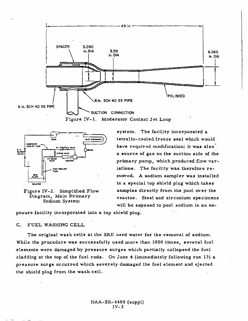
SPACER 3.090
\ in.D1A 3.59
I in. DIA 6.065 in. DIA
6 in.
8 in. SCH 40 SS PlPE
SS PlPE
SUCTION CONNECTION ' . k' Figure IV-1. Moderator Coolant Jet Loop
system. The facility incorporated a
tetralin- cooled freeze seal which would
have required modification; i t was also
a source of gas on the suction side of the
pr imary pump, which produced flow var -
iations. The facility was therefore r e -
m w e d . A sodium sampler was installed
in a special top shield plug which takes
Figure IV- 2. Simplified Flow samples directly f rom the pool over the Diagram, Main P r imary reactor . Steel and zirconium specimens
Sodium System will be exposed to pool sodium in a n ex-
posure facility incorporated into a top shield plug.
C. FUEL WASHING CELL
The original wash cel ls a t the SRE used water for the removal of sodium.
While the procedure was successfully used mdre than 1000 times, severa l fuel
.elements were, damaged by p r e s su re surges which partially collapsed the fuel
cladding a t the top of the fuel rods. On June 4 (immediately following run 13) a
p ressure surge occurred which severely damaged the fuel element and ejected
the shield plug f rom the wash cell.
NAA- SR- 448 8 ( suppl) IV- 3

A test apparatus was fabricated and an extensive ser ies of tests conducted to
determine the cause of the pressure excursions and to develop an improved wash-
ing procedure. The tes ts indicated that the pressure surges were caused by sub-
merging a substantial quantity of sodium under water. Apparently the drain holes
in the cylindrical holddown tube were plugged sufficiently, with decomposition
products from the tetralin leaks which had occurred, to prevent complete drain-
ing of the sodium. (The holddown tube has been modified; see Section IV-E).
Following the water tests a ser ies of washings was conducted aith steam.
These tests were highly successful in removing substantial quantities of sodium
without pressure buildup. The steam cleaning left NaOH residue, however, which
can be removed with water. The new wash cells therefore incorporate steam
cleaning and a water rinse. A hydrogen recombiner has been added to the system
because the gases from the washing operation a r e vented into the radioactive vent
system, into which a i r leakage i s unavoidable.
--
D. INSTRUMENTATION MODIFICATIONS
1. Fission Product Monitor
The analyses of core cover gas (helium) samples after run 1 4 indicated a 133
large increase in Xe activity. This euggested that continuous monitoring of
the ~e 133 activity would provide a reliable means of detecting fuel element clad-
ding failures. Techniques were developed for gas sampling during reactor oper-
ation. The detector i s a scintillation spectrometer-.used in the system shown
schematically in Figure IV-3. .Gas flow through the spectrometer i s at a rate of
about 0.3 d m . The differential analyzer i s adjusted to discriminate in favor of 13 3
the 0.081-Mev gamma from Xe . If the level exceeds a predetermined amount,
a signal i s provided to an annunciator a larm in the SRE control room. Purge 133 lines a r e provided to permit calibration with a sample of Xe .
2. Reactor Transient Monitor
The transient monitor i s a fas t data-recording system to record selected
parameters during off-normal conditions. It was installed to provide detailed
data for diagnosis of abnormal occurrences.
In operation seven selected signals a r e recorded continuously a t a fast
tape speed on a continuous-loop magnetic tape. Three heads a r e provided for
recording, reproducing, and erasing. The recording and erasing heads a r e in
NAA- SR-4488 (suppl) IV-4

REACTOR VESSEL
FLOW ALARM
A
PURGE R SAMPLE LINE *
L r VAPOR TRAP FILTER
Figure IV- 3 . F i s sion-Gas ~ e t e c t i o n System
el AMPLIFIER
DIFFERENTIAL ANALYZER
LOG COUNT RATE METER
LOG COUNT I RATE / RECORDER

continuous operation. Upon receipt of an off-normal signal, such a s a reac tor
sc ram, the reproducing head i s activated, and the information is t ransfer red
f r o m the continuous tape to a second tape recorder . Because the continuous tape
has a circuit t ime of 8 min, the system has an 8-min "memory"; i. e . , informa-
tion i s recorded on the second tape which covers the operating period beginning
8 min before the activating signal i s received. Up to 4 h r of recorded data can
be s tored on the second tape after receipt of the activating signal.
Typical reactor pa ramete r s which will be monitored by the t ransient
monitor a re : (a) neutron flux level, (b) reactor period, (c) a selected fuel chan-
nel outlet temperature, (d) a selected in-fuel temperature, ( e ) moderator coolant
temperature, (f) p r imary coolant flow, and (g) sh im rod position. -
3. Reactor Temperature Measurements
Two recorders have been added to record data f r o m thermocouples in-
stalled in some of the fuel slugs and in special tubing which se rves a s wi re wrap --
to separa te the fuel rods (see Section IV-E). Chart speed is 12 in. / h r and each
point ia recorded a t 50-sec intervals. The recorders a r e f a s t e r than previous.
equipment by a factor of six and will provide more detail in fuel element temper-
a tur e histories.
There a r e eight special fuel elements with in-fuel and wire-wrap thermo-
couples. Their locations in the core a r e indicated in Figure IV-4. The thermo-
couple locations a r e shown in Figure IV-5.
4. Operation Events Recorder
Three 20-pen recorders have been installed to indicate when any of 60
functions i s being performed. The recorders a r e of the off-on type and therefore
measure only the t ime duration of events being monitored. The following will be
monitored:
10 reac tor s c r a m circui ts 4 safety-rod- out circui ts
9 reac tor s c r a m bypasses 4 shim-rod-in slow drive circuits
3 reac tor setback circui ts 4 shim- rod-out slow drive circuits
3 reactor setback bypasses 2 shirn-rod-in fas t dr ive circuits
9 plant protective sys tem a l a r m s 2 shim- rod-out f a s t dr ive circuits
4 control circui t interlock bypasses 2 types of automatic control (tem-
4 safety-rod-in circui ts perature o r flux). -
NAA-SR-4488 (suppl) IV- 6

A 8 B IN FUEL THERMOCOUPLES C WRAP AROUND THERMOCOUPLES
w
Figure IV-4. c o r e Location of Instrumented Fuel
The recorders have synchronous chart drives, and the charts can be
simultaneouely time-marked by operation of a switch. They therefore provide
an accurate chronology of operating events and aid in separating cause and effect
in analysis of reactor operation.
5. F l u x / Power Deviation Circuit
As a supplement to the standard plant protective system, a flwc/power
deviation circuit has been added. The function of the circuit is to prevent large
mismatches between heat generation and heat removal rates. Reactor power a s
determined f rom neutron flux level i s compared to power a s determined from
NAA-SR-4488 (suppl) IV- 7

HANGER SUPPORTROD \
ELEVATION OF SPECIAL THERMOCOUPLES FUEL CLUSTER No.
-4 -7 -9 -10 - 1 1 -12 -13 -14
A AND B IN-FUEL THERMOCOUPLES C WRAP-AROUND THERMOCOUPLE
ORIFICE PLATE \ \ TOP OF MODERATOR
/ FUEL CHANNEL
LOCATION OF WRAP-AROUND THERMOCOUPLE ON FUEL CLUSTER AND IN-FUEL THERMOCOUPLES
FUEL CHANNEL OUTLET THERMOCOUPLES
TOP OF MODERATOR CAN
WRAP AROUND THERMOCOUPLE
IN FUEL THERMOCOUPLES _ -
STRAINER
FUEL ELEMENT ASSEMBLY IN MODERATOR FUEL CHANNEL
Figure IV- 5. Thermocouple Location of Instrumented Fuel .
NAA-SR-4488 ( s u p s ) IV- 8
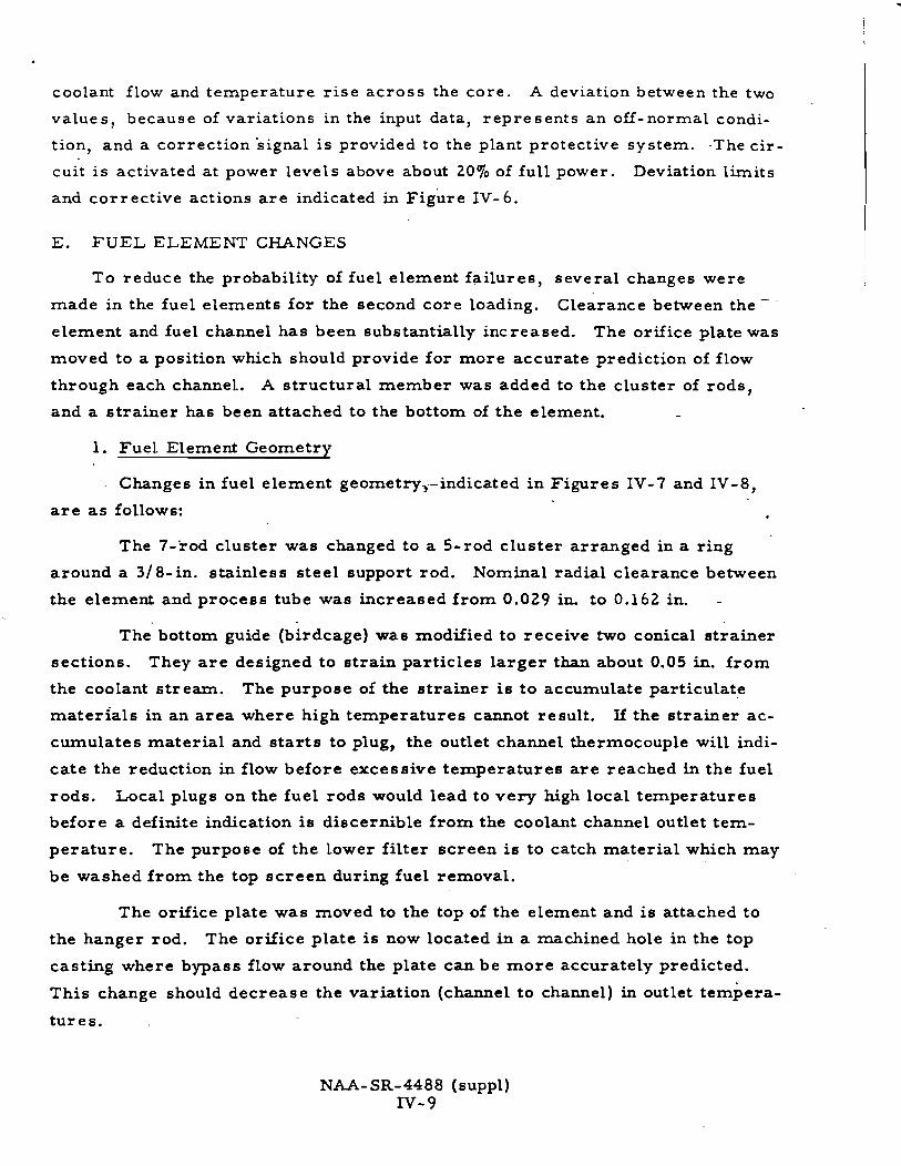
coolant flow and temperature r ise across the core. A deviation between the two
values, because of variations in the input data, represents an off - normal condi-
tion, and a correction signal is provided to the plant protective system. -The cir-
cuit i s activated at power levels above about 20% of full power. Deviation l M i t s
and corrective actions a r e indicated in ~ i ~ u r e IV- 6.
E. FUEL ELEMENT CHANGES
To reduce the probability of fuel element failures, several changes were
made in the fuel elements for the second core loading. Clearance between the - -
element and fuel channel has been substantially increased. The orifice plate was
moved to a position which should provide for more accurate prediction of flow
through each channel. A structural member was added to the cluster of rods,
and a strainer has been attached to the bottom of the element. -
1. Fuel Element Geometry
Changes in fuel element geometry,-indicated in Figures IV-7 and IV-8,
a r e a s follows:
The 7-rod cluster was changed to a 5-rod cluster arranged in a ring
around a 318-in. stainless steel support rod. Nominal radial clearance between
the element and process tube was increased f rom 0.029 in. to 0.162 in. -
The bottom guide (birdcage) was modified to receive two conical strainer
sections. They a r e designed to strain particles larger than about 0.05 in. f rom
the coolant stream. The purpose of the strainer i s to accumulate particulate
materials in an a rea where high temperatures cannot result. If the strainer ac-
cumulates material and s ta r t s to plug, the outlet channel thermocouple will indi-
cate the reduction in flow before excessive temperatures a r e reached in the fuel
rods. Local plugs on the fuel rods would lead to very high local temperatures
before a definite indication i s discernible f rom the coolant channel outlet tem-
perature. The purpose of the lower filter screen is to catch material which may
be washed f rom the top screen during fuel removal.
The orifice plate was moved to the top of the element and i s attached to
the hanger rod. The orifice plate i s now located in a machined hole in the top
casting where bypass flow around the plate can be more accurately predicted.
This change should decrease the variation (channel to channel) in outlet tempera-
tures.
NAA- SR-4488 (suppl) N- 9

THERMAL POWER PttH) s C P ATw
INCREASED FLOW CONSTANT
HIGH FLUX TRANSIENT CONSTANT
LOW FLUX TRANSIENT CONSTANT
R I
NEUTRON
MEASUREMENT
0- - THERMAL POWER
MEASUREMENT R3
ITRANSISTORIZED 1 ELECTRONIC
t t PLANT PROTECTIVE SYSTEM
DEVIATION CIRCUIT
FLOW 1 FLUX I POWER PROTECTION I DECREASE
INCREASE
CONSTANT
CONSTANT
CONSTANT
I. ALARM
2. SETBACK
3. SCRAM
Figure IV-6. Operating Limits on F 1 u x ' ~ o w e r Deviation Circuit
CONSTANT CONSTANT
CONSTANT
INCREASE
DECREASE
DECREASE
INCREASE
,DECREASE
CONSTANT
CONSTANT

SECTION A A
SECTION B B
STRUCTURAL
f MEMBER
SECTION CC
CRUCIFORM
ORIFICE --- PLATE
THERMOCOUPLE LEAD
THERMOCOUPLE JUNCTION
5 -ROD CLUSTER
STRAINER
Figure IV- 7. Thorium- Uranium Five- Rod and Seven- Rod Clusters
NAA- SR-448 8 (suppl) IV- 1 1

W I R E 0.09 -
0.029 - in. RAD l A L CLEARANCE
1
in. 0 0 - 2.805 in.
)5 in.
Figure IV-8. Thorium-Uranium Fuel Element
NAA-SR-4488 (suppl) IV- 12

The hanger rod and holddown tube of the f i r s t core loading has been r e -
placed by a crucrform section, a s shown in Figure IV-9, to reduce potential hold-
up of sodium and subsequent difficulties in the wash cell.
2. Fuel Element Instrumentation
Fuel element instrumentation has been improved. The two outlet channel
thermocouples (one spare) on each fuel element a r e far ther into the cooling chan-
nel than was previously the case . The thermocouple junctions have been placed
direct ly in the coolant s t r e a m ( see Figure IV-9) to improve response time.
Figure IV-9. Cruciform Holddown on Fuel Element
Eight fuel elements have special thermocouples. Each of the eight ele-
ments has two thermocouples in the fuel slugs. Elevation of the thermocouples
in the fuel rods i s shown in Figure IV-5. Six of the eight elements have a n addi-
tional thermocouple in special tubing, which serves a s a wire wrap for fuel rod
spacing; these thermocouples m e a s u r e local sodium temperatures . Each of the
wire-wrap thermocouples i s opposite an in-fuel thermocouple to facilitate heat
f lux determinations.
F. EFFECTS OF MODIFICATIONS ON REACTOR OPERATIONS
The modifications es sentially eliminate the possibility of major contamina-
tion of the p r imary coolant. The new fuel element has adequate clearance in the
N U - S R - 4 4 8 8 (suppl) IV- 13

fuel channel to permit routine removal even-in the event of fuel distortion or a
major cladding failure. . The possibility of multiple fuel element failures has
been markedly reduced through urre of the fission-gas monitor on the reactor,
which should indicate faults in the cladding. Better control of outlet channel tem-
peratures through relocation of the orifice plates should reduce thermal s t resses
in moderator cans. The new transient monitor and the operation events recorder
provide detailed data during periods of off-normal conditions. which should aid
greatly in understanding the reactor system. - -
NAA-SR-4488 ( S U P ~ ~ )
IV- 14

V. SUMMARY
Investigation into the SRE fuel element damage has been completed. A gen-
era l picture of both causes and effects has been reached, andresumptionof opera-
tion of the SRE has been recornrnended.
CAUSE OF FUEL ELEMENT DAMAGE
Failure of the fuel cladding can be attributed to abnormal temperatures
caused by interference with heat removal capability by decomposition products
of tetralin. Local blockage of coolant pas sages prevented an adequate supply of
coolant f rom reaching par ts of the fuel elements.
The fuel cladding failure was caused by (1) thermal cycling and expansion of
the-fuel slugs until the cladding burst, and (2 ) formation of low melting alloys of
uranium and the iron, nickel, and chromium constituents of 304 stainless steel
used for cladding. .--
1) Failure by thermal cycling and expansion was'indicated by examinatioo
of the top sections of the element from R-24. The cladding was split '
although there was no appreciable change in i ts ductility, and no evi-
dence of Fe-U diffusion. The thermal cycling was probably caused by
pulsing of sodium-sodium vapor in the partially obstructed process
tubes, which in turn produced corresponding variations in coolant flow
and fuel temperatures. Careful examination of the records of channel
outlet temperatures showed indication of cyclical variations in several
channels with a period of approximately 2 min.
2) Chemical analyses definitely established the presence of iron-uranium
alloys, both in and near regions of cladding failure. Examination of
the element f rom R-24, made by sectioning the moderator element in
which the element was stuck, revealed about 800 g of Fe-U alloy near
the eutectic composition.
B. CAUSES OF REACTIVITY CHANGES
The major reactivity changes requiring explanation a r e three: (1) the slow
increase of about 0.3% during run 13, (2) the loss of about 1.2% during the f i r ~ t
par t of run 14, and (3) the rapid insertion of about 0.3% during run 14 which caused

a power transient. All causes of the reactivity changes a r e directly related to
the presence of tetralin decomposition products in the reactor, and should not
present difficulties in future operation.
1) The most likely causes of the 0.3% reactivity increase which occurred
in a 6-hr period on May 30, 1959, a r e the displacement of some of the
core sodium by bubbles and an increase in moderator temperature.
This reactivity change, determined after the termination of run 14
from records of control rod position, is in fact the best indicator of
the s ta r t of the tetralin leak.
2) The reactivity 10s s of about 1.270 during the fir at three or four days of
run 14 i s due to entry of sodium into the moderator cans in positions
R-10 and R-42. The failures were probably caused by abnormal tem-
perature conditions in the core during run 14.
. - 3) The most likely cause of the 0.370 reactivity increase, which put the
reactor on a 7.5- sec period and produced an excursion to about 70Sof
full power, i s the expulsion of sodium f rom several fuel channels in
quick succession. It i s a lso possible that the cause of the reactivity
insertion was the upward movement of a large bubble between modera- -
tor cans toward the center of the core.
C. CURRENT CONDITION O F REACTOR SYSTEM
In order to determine operability of the SRE after the fuel e l emen~ damage,
it was necessary, a s par t of the investigation, to determine its physical condi-
tion. In general it was concluded that there has been little change and the system
condition is satisfactory; however, the probability of moderator-can failure may
have increased.
The zirconium cans a r e known to be hydrided. Specimens taken f rom sev- -
era1 of the cans removed f rom the reactor indicated hydriding over a range of
about 100 to 1000 ppm of hydrogen. Ductility of the weld material in the modera-
tor cans has been reduced by the hydriding.
With the addition to the primary system of substantial quantities of carbon,
carburization of the stainless steel, with resultant loss in ductility, i s a pbssibil- . ity. Tests of stainless steel specimens show that no appreciable amount of car-
burization has occurred except in those sections of the fuel cladding near failures.
NAA- SR-4488 (suppl) v- 2

Examination of specimens of fuel cladding (0.01 0-in. wall) taken f r o m points dis-
:ant f r o m fai lures, sections of the upper element hardware, and a small section
of piping, prove that no general carburization occurred.
The nitrogen purge operation before run 14 was suspected of providing con-
ditions fo r nitriding of the s tainless steel; however, no evidence of nitriding was
found.
It i s known that fission products have deposited on the walls of a l l p r imary 90 2
- . system components. Jn part icular , Sr i s present to the extent of about 314 pclcrn .
While the presence of this isotope i s of little concern in maintenance operations
around pr imary system components (it is a pure beta emitter), i t is of importance
in any operation in which the piping i s welded.
D. MODWICATIONS TO AVOLD RECURRENCE -
To minimize the possibility of a second major fuel element fai lure a t SRE,
modifications have been made to the system. Tetral in i s no longer used a s -- a
service coolant. The freeze- sea l s on the sodium pumps a r e now cooled with NaK.
Kerosene i s used for auxiliary cooling, but only in locations where a t leas t two .
b a r r i e r s exist between the organic mate r i a l and sodium.
A fission-gas monitor has been added to the reac tor system to provide a con-
tinuous check on radioactivity of the cover gas. This instrument will inform the
operators of the beginning of a cladding failure, and the reac tor can be shut down
before extensive damage occur s.
E. REACTOR OPERABILITY
The general conclusion reached regarding operability of the SRE i s that there
has been no important change in i ts physical condition a s a resul t of the fuel ele-
ment damage to the f i r s t core. The one reservat ion in this regard is that the
probability of moderator can fai lure may have increased. The sodium may be
saturated with carbon, and tempera ture l imits have been imposed on operation
until i t has been demonstrated that the carbon content has been reduced to a sat-
isfactorily low level.

IV- D- 10 / T a b l e IV- D- 1, I
P a g e L i n e
e n t r y 1
e n t r y 7
I n s e r t De le t e
IV- D- 3 I 1 1
-0.03 t o -0.05
0 t o 0.7
e n t r y 1 2
NAA- SR-4488 (suppl) A- 1
-0 .10%
0.01 t o 0.02

REFERENCES
1. A. A. J a r r e t t et a l . , "SRE Fuel Element Damage, an Interim Report," NU-SR-4488 (November 15, 1959)
2. W. J . Freede , "SRE Recovery Operations," (to be published)
3. G. Deegan -- et a l . , "Design Modifications to the SRE During F Y 1960," NU-SR-5348 (Rev. ) (February 15, 196 1)
4. Atomics International Staff, "Supplement to Hazards Summary for Thorium- Uranium Fuel in the Sodium Reactor Experiment," N U - S R - 3 175 (Rev. ) (to be published) (April 8, 1960)
5. J . L. Ballif, " Metallurgical Aspects of the SRE Fuel Damage Episode," NU-SR-4515 (to be published)
6. J. J . Gill, "Zirconium Moderator Cladding Irradiated in the Sodium Reactor Experiment," NU-SR-5970 (December 15, 1960)
7. R: S. Hart, "Investigation of Radioactivity in Coolant of SRE," (to be pub- lished)
8. F. Fi l lmore, "Reactivity Effects in SRE," NU-SR-5898 (to be published)
9. W. J. Anderson and G. V. Sneesby, "Carburization of Austenitic Stainless Steel in Liquid Sodium," N U - S R - 5282 (September 1, 1960)
10. B. Lkstman and F. Kerze, The Metallurgy of Zirconium, (lSt ed. , New York, McGraw- Hill Book Co. , Inc., 1955) p 509
11. J. C. Bokras, "Effect of Sodium on Mechanical Proper t ies of Zirconium," NU-SR-1867 (June 15, 1957)
NAA- SR- 4488 (suppl) R- 1
Top Related