


Languages
Pages
Legal


ASSEMBLY INSTRUCTION
FLEXMO™ VAN EQUIPMENT
Professional Service-Car-Systems
Lighter.Flexible. Efficiently.

©2016-05 FLEXMO™ by KÖGL GmbH www.flexmo.de Page 2 of 29
Introduction – Original assembly instruction
1. Introduction 3
2. Overview installation material and tools 4 3. Installation of equipment 5
4. FLEXMO floor plates 23 5. Loading information of FLEXMO equipment 24 6. Spare part and accessories 25

©2016-05 FLEXMO™ by KÖGL GmbH www.flexmo.de Page 3 of 29
1. Introduction
This manual describes the correct installation of the FLEXMO modules and the FLEXMO floor plates in your vehicle. Before fitting out a van with FLEXMO it is important that the information in this manual has been read in full and unserstood. Depending on your order and your vehicle, not all points of this manual are applicable. Check before installation if you have received the goods completely. If you have damaged or missing parts, so please contact directly your FLEXMO contact person. We recommend the installation of the FLEXMO modules on a FLEXMO van floor.
A van equipment is approved by the legislator as a load.
Therefore shall be provided between passenger´s cell and
loading space a appropriate safety grid as a personal security.
Read this manual, take notice and keep it any time
available for later looking-up.
©2016-05 FLEXMO™ by KÖGL GmbH www.flexmo.de Page 4 of 29
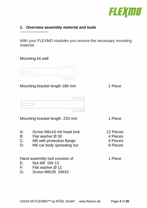
1. Overview assembly meterial and tools With your FLEXMO modules you receive the necessary mounting material.
Mounting kit wall
Mounting bracket length 180 mm 1 Piece
Mounting bracket length 220 mm 1 Piece
A: Screw M6x16 mit head lock 12 Pieces B: Flat washer Ø 30 4 Pieces C: M6 with protection flange 4 Pieces D: M6 car body spreading nut 8 Pieces Hand assembly tool consists of 1 Piece E: Nut M8 SW 13 F: Flat washer Ø 11 G: Screw M6x35 SW10

©2016-05 FLEXMO™ by KÖGL GmbH www.flexmo.de Page 5 of 29
Mounting kit floor H: Quick drive-in nut M6 8 Pieces
I: Srew M6x16 with head lock 8 Pieces
Required tools - Adhesive tape - Mark pencil - Combination spanner SW 10 and SW 13 - Drilling machine and drill Ø 10 - Wrench SK 4 - Torque key to 10 Nm

©2016-05 FLEXMO™ by KÖGL GmbH www.flexmo.de Page 6 of 29
2. Assembly of the equipment
Overview of the single steps:
3.1 Remove wall covering (partly necessary) 3.2 Place the floor in the van 3.3 Position modules in the van 3.4 Determine the mounting point in car body 3.5 Determine the mounting point in the floor 3.6 Take out units and flooring of the van 3.7 Position the screw at the car body 3.8 Position the screw at the floor 3.9 Final assembly of the floor 3.10 Assembly panels (partly necessary) 3.11 Assembly modules on the floor 3.12 Assembly modules on the car body 3.13 Final assembly

©2016-05 FLEXMO™ by KÖGL GmbH www.flexmo.de Page 7 of 29
3.1 Removal the the panel (partly necessary)
Now you can define position of the mounting bracket in the
supporting structure
Should the panel be across the carrying structure you have to remove it to define the position to screw of the mounting
bracket.

©2016-05 FLEXMO™ by KÖGL GmbH www.flexmo.de Page 8 of 29
3.2 Mounting panel floors in the van
Put the panel loosely in the van. According to vehicle the floor is composed from one or several parts.

©2016-05 FLEXMO™ by KÖGL GmbH www.flexmo.de Page 9 of 29
3.3 Mounting modules in the van
Remove first all loose parts from the module as for example
case and box.
To simplify the work, you can also remove the drawers from
the modules.
Put now the modules to the desired position in the vehicle.
Removal push tray: Unlock the runner (drawer) on both sides and pull it from the
slide rail.

©2016-05 FLEXMO™ by KÖGL GmbH www.flexmo.de Page 10 of 29
With the positioning of the modules to the side
panels you probably have to consider the pre-
removed lining panels.

©2016-05 FLEXMO™ by KÖGL GmbH www.flexmo.de Page 11 of 29
3.4 Definition mounting points on the car body
Number of mounting points:
Height till 1000 mm
1 Wall bracket
per side
Height from 1001-1500mm
2 Wall bracket per side
Height over 1500 mm
3 Wall bracket
per side
Mount always the upper wall pracket so high as possible.
Evenly spread the remaining wall pracket.
With 2 modules in-line the sequently side panels are to be
screwerd together with each other and to use unique a mounting
variation like shown on top.
Avoid direct contact of the modules with the side panels
of the car body to avoid driving noises.
Vanaf 1.50 mtr
©2016-05 FLEXMO™ by KÖGL GmbH www.flexmo.de Page 12 of 29
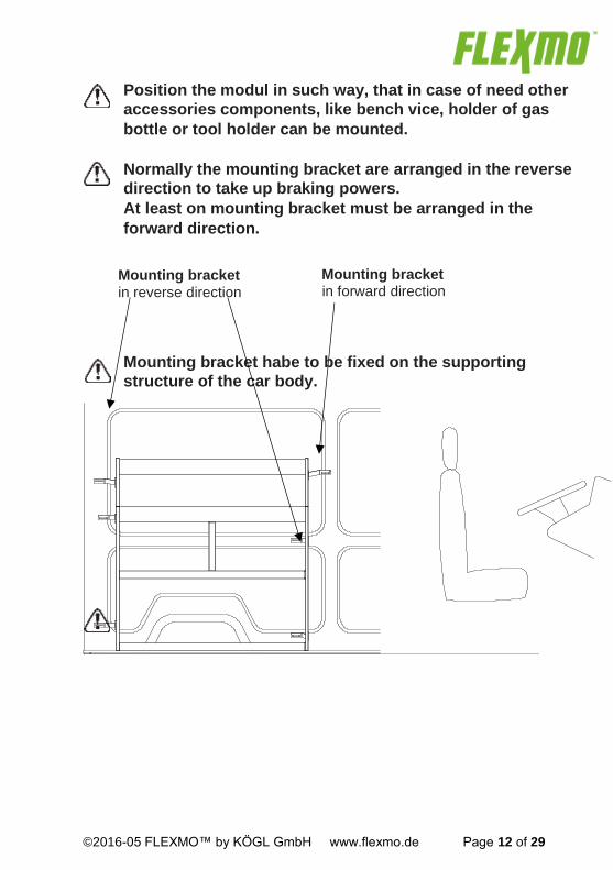
Mounting bracket
in reverse direction
Mounting bracket
in forward direction
Position the modul in such way, that in case of need other
accessories components, like bench vice, holder of gas
bottle or tool holder can be mounted.
Normally the mounting bracket are arranged in the reverse
direction to take up braking powers.
At least on mounting bracket must be arranged in the
forward direction.
Mounting bracket habe to be fixed on the supporting
structure of the car body.

©2016-05 FLEXMO™ by KÖGL GmbH www.flexmo.de Page 13 of 29
Mounting bracket have to be adapted according position of the
module and the supporting structure!

©2016-05 FLEXMO™ by KÖGL GmbH www.flexmo.de Page 14 of 29
Fix this side of the car body
with 4 screw position
Diese Seite an die Karosserie mit mindstens 4
Spreitzmuttern
Fix this side on the module
with 2 screw position
Use a bench vice with rounded aluminiu-bracket to bend
the mounting bracket.
Avoid frequent postbending because it can lead to cracking and
therefore break of the mounting bracket!
Fix the bent mounting bracket sturdy on the module. Mark all required mounting points to the car body
©2016-05 FLEXMO™ by KÖGL GmbH www.flexmo.de Page 15 of 29
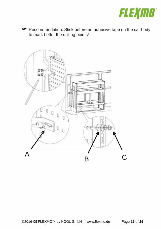
Recommendation: Stick before an adhesive tape on the car body
to mark better the drilling points!
A B C

©2016-05 FLEXMO™ by KÖGL GmbH www.flexmo.de Page 16 of 29
3.5 Determine mounting points on floor Mark all mounting points of the module side panels on the floor. Every side panel will be fixed with minimum 4 screws on the floor.
©2016-05 FLEXMO™ by KÖGL GmbH www.flexmo.de Page 17 of 29
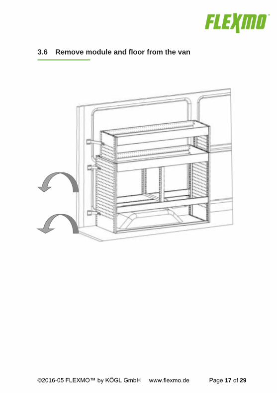
3.6 Remove module and floor from the van
©2016-05 FLEXMO™ by KÖGL GmbH www.flexmo.de Page 18 of 29
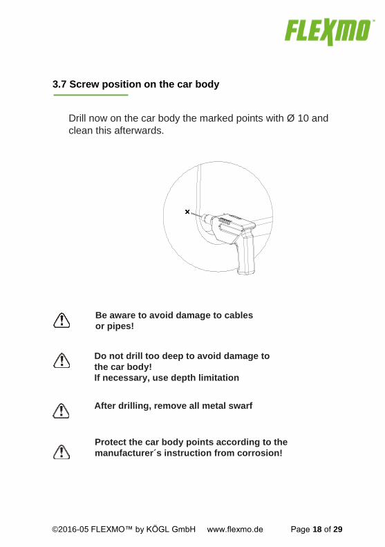
After drilling, remove all metal swarf
Protect the car body points according to the
manufacturer´s instruction from corrosion!
3.7 Screw position on the car body
Drill now on the car body the marked points with Ø 10 and
clean this afterwards.
Do not drill too deep to avoid damage to
the car body!
If necessary, use depth limitation
Be aware to avoid damage to cables
or pipes!

©2016-05 FLEXMO™ by KÖGL GmbH www.flexmo.de Page 19 of 29
Fitting spread nut on car body
Insert the expanding nut D into the drill hole. Turn screw G with washer F and nut E into the spread nut D. Keep hold nut E with an open-end spanner and turn in screw G as long as spread nut D is tight.
D E F G
The spread nut must be fixed directly on the car body.

©2016-05 FLEXMO™ by KÖGL GmbH www.flexmo.de Page 20 of 29
Only use the supplied thread drive-in nut.
3.8 Screw points on floor
Drill through the marked points with Ø 10 in the floor.
It is important that the holes are drilled exactly
straight and in the correct position. Turn the floor and insert on the back side the delivered M6 thread
drive-in nut in the drilling holes.
H

©2016-05 FLEXMO™ by KÖGL GmbH www.flexmo.de Page 21 of 29
3.9 Final assembly floor
Position the floor in the van again.
The mounting is carried out on available screw or lashing lug!
See for this at chapter 4.
3.10 Mounting Lining Panels
Remove any lining panels supplied by van manufacturer, so they
can be reinstalled. If nessary, these must leave open at the mounting points place.
Lining Panel must not be fixed between mounting bracket
and car body.
3.11 Mounting modules on floor
Position the moduels in the van. Place the modules in the desired
Position above the floor. Fix the unit with screws H handtight

©2016-05 FLEXMO™ by KÖGL GmbH www.flexmo.de Page 22 of 29
into the floor.
3.12 Mouting modules to car body
Screw the mounting bracket not fully tighten witch screws A.
Fasten all screws and nuts using a torque wrench 7-9 Nm.
3.13 Final assembly
Now you can put back drawers, suitcase and the like in the modul.
Your FLEXMO™ - Vehicle equipment is now
fit for service!
Check regularly all screws for tightness. At least every
5000 km or after an emergency braking!

©2016-05 FLEXMO™ by KÖGL GmbH www.flexmo.de Page 23 of 29
4. FLEXMO floor Please observe the supplied manufacturer´s installattions. 1. Lift the lashing rings on the floor and remove them.
All other components which are screwed to the floor or rather through the floor screwed must be removed.
2. Depending on the type of vehicles the nail strips are included
in the standard delivery. These laths prevent sagging of the floor where the van floor can not provide support.
3. Position the panel floor on the van floor.
We recommend to cant the base plate in the van. Depending on vehicle type the floor is consisting of one or several pieces
4. An Adhesive kit or lash trays mounting set is optionally
available.

©2016-05 FLEXMO™ by KÖGL GmbH www.flexmo.de Page 24 of 29
5. Loading information of the parts
This label is attached to your FLEXMO in-vehicle equipment.

©2016-05 FLEXMO™ by KÖGL GmbH www.flexmo.de Page 25 of 29
6. Spare parts and accessories
Spare parts and accessories are available at your local dealer or from www.flexmo.de
©2016-05 FLEXMO™ by KÖGL GmbH www.flexmo.de Page 26 of 29
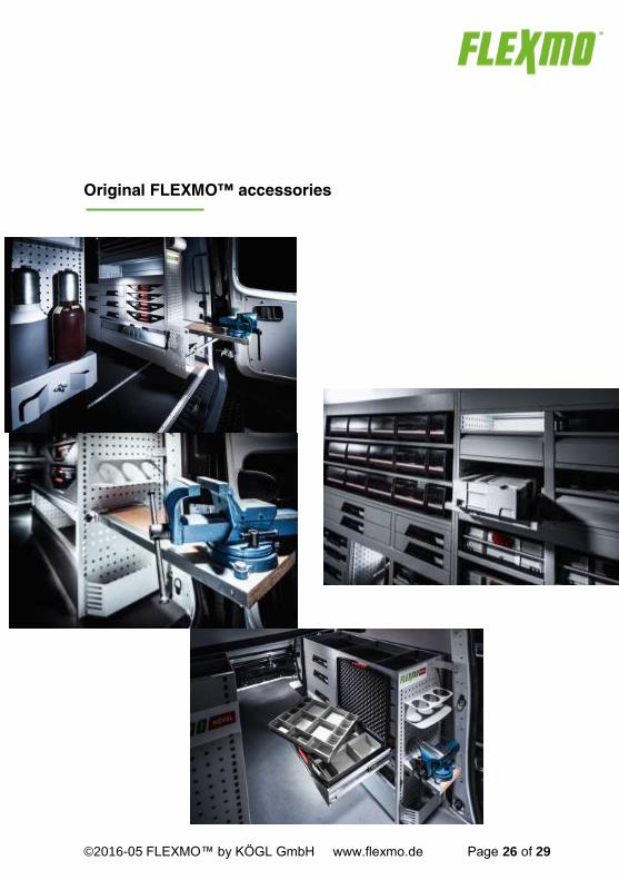
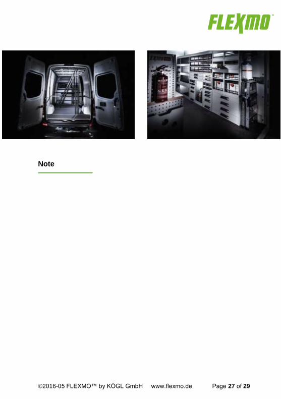
Original FLEXMO™ accessories
©2016-05 FLEXMO™ by KÖGL GmbH www.flexmo.de Page 27 of 29
Note

©2016-05 FLEXMO™ by KÖGL GmbH www.flexmo.de Page 28 of 29
Download in italian Download in french Download in spanish
FLEXMO™ Center close to you

©2016-05 FLEXMO™ by KÖGL GmbH www.flexmo.de Page 29 of 29
FLEXMO™ is a registered trade mark of KÖGL GmbH, Bubesheim. No liability for printing errors. Printed colours may differ slightly from the actual colours.Texts and pictures may contain equipment which is not part of the standard portfolio. Errors and mistakes as well technical changes are subject to change.
FLEXMO™ Professional Service-Car-Systems
by KÖGL GmbH Industriestraße 2
D-89347 Bubesheim-Günzburg
[email protected] |www.flexmo.de
Top Related