


Languages
Pages
Legal


1
Application of STAR-CCM+ to
Helicopter Rotors in Hover
Lakshmi N. Sankar and Chong Zhou
School of Aerospace Engineering, Georgia Institute of Technology, Atlanta, GA
Ritu Marpu Eschol
CD-Adapco, Inc., Orlando, FL

2
Background
▪ Over the past several decades, engineers have used a variety of
tools for modeling and improving rotor design.
▪ An engineering model called a “Lifting Line Model” with a look up of
2-D airfoil load characteristics look-up table is often used during
early stages of design, with empirical corrections for compressibility,
and sweep.
▪ During a second “preliminary” stage of design, hybrid CFD + Lifting
Line methods would be used.
▪ During later “detailed design” stages, a more accurate CFD based
model is used to refine the design.
▪ STAR-CCM+ is a valuable tool for this final detailed design.
▪ In this work, we show selected examples of three types of rotors, to
see how a preliminary and detailed analysis may be done.

3
Overview
▪ Introduction
▪ Detailed Analysis/Design Tool (STAR-CCM+)
▪ Hybrid CFD Methodology (GT-Hybrid)
➢ Wake Model (Single Tip Vortex)
➢ Vortex Core Modeling
➢ Full Span Wake Model
▪ Performance Predictions and Validation
➢ Sikorsky S-76 Helicopter Rotor with swept Tip
➢ Helicopter Rotor with Swept Anhedral Tip
➢ Coaxial Rotor
▪ Concluding Remarks
4
Objectives
▪ Apply STAR-CCM+ Analysis Wake-capturing Models To S76
Rotors In Hover
▪ Validate The Analysis For S76 In Hover
▪ Compare Predictions With GT-Hybrid (Preliminary Design/Analysis
Tool)
▪ Analyze The Effects Of The Anhedral Tip On The Inflow Distribution
▪ Explain Why The “efficiency” is Improved By The Anhedral Platform
▪ Analyze a Coaxial Rotor

5
STAR-CCM+ Computational Domain

6
Parameters for the S-76 Model Simulations
Mach Number at the Tip 0.65
Reynolds Number 1.20E+06
Ds 1.60E-06
y+ of first point off the wall ~1
Rotor Radius 56 inches
C 3.1inch
▪ Wake capturing model
▪ Unsteady simulations (7 to 20 revolutions)
➢ Time step : 1 Deg. Azimuth
➢ Sub-iterations: 10 to 15 per time step
▪ Physics Model
➢ Coupled Energy
➢ Ideal Gas
➢ K-Omega SST, fully turbulent flow

7
Mesh
▪ Overset Mesh Topology
The mesh for the rotor region Background
MeshThe mesh around the rotor blade
The cut plane of the rotor regionBlade surface grid

8
Refined Mesh Region

9
GT-Hybrid CFD Methodology (Preliminary
Design Tool)
▪ Hybrid Methodology
─ Reynolds Averaged Navier-Stokes (RANS)
methodology for flow over blades.
─ Lagrangian free wake to model far wake.
─ The near wake is captured inherently in the
Navier-Stokes analysis.
─ The far wake and effect of other blades
accounted for using wake model.
─ Wake induced velocities are applied as
boundary condition on Navier-Stokes domain.
Schematic View of the Hybrid Method

10
Wake Model (Single Tip Vortex)
▪ Lagrangian Free Wake model
─ Single concentrated tip vortexassumption
─ Collection of piece-wise linearbound and trailed vorticities
─ Strength of the vortex elementsis set to be equal to the peakbound circulation
─ Vortex shedding point basedon centroid of trailed circulationbetween the tip and location ofpeak bound circulation
─ Vortex trailed at discreteazimuthal intervals.
─ Vortex elements convectedthrough freestream velocitiesand wake induced velocities

11
▪ Vortex core growth using the Bhagwat – Leishman (2002) core
growth model
Vortex Core Modeling
▪ Wake behind any lifting surface must be considered as a viscous
phenomenon
▪ Velocity induced by a vortex with Vatistas (1991) core (n = 2)
2
2
1
10/1
2
0
2
21
21
4 r
r
r
rr
rrrr
rrV
nn
c
n
v
c
a
V
zzr
Re1
4
1
0

12
Full Span Wake Model (FSWM)
▪ The baseline wake model
assumes a single concentrated
tip vortex trailing from a region
near the blade tip.
▪ This assumption would be
physically less accurate for
rotors in low speed forward
flight.
▪ Single tip vortex is replaced by
user specified multiple vortex
segments trailed from all the
blades.
▪ FSWM is based on vorticity
conservation laws.
13
Grid Used for Numerical Studies
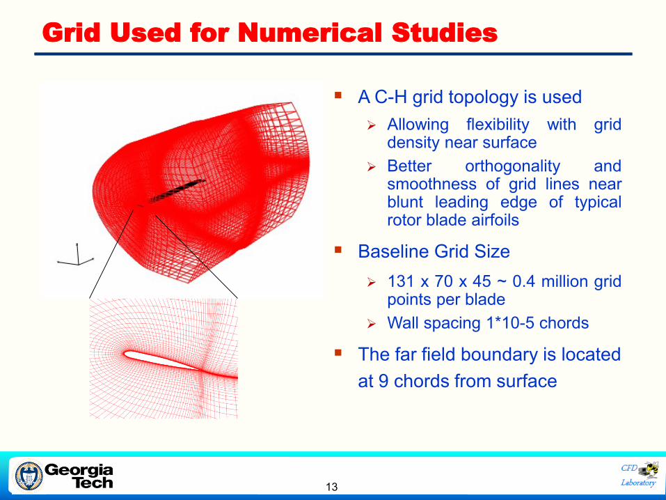
▪ A C-H grid topology is used
➢ Allowing flexibility with griddensity near surface
➢ Better orthogonality andsmoothness of grid lines nearblunt leading edge of typicalrotor blade airfoils
▪ Baseline Grid Size
➢ 131 x 70 x 45 ~ 0.4 million gridpoints per blade
➢ Wall spacing 1*10-5 chords
▪ The far field boundary is located
at 9 chords from surface

14
Baseline S-76 Rotor Characteristics
Number of blades 4
Radius 56.04”
Nominal Chord 3.1”
Equivalent Chord 3.035”
Tip Taper 60% c
Root Cutout 19% R
Sweep (leading-edge) 35 degrees at 95% R
Solidity 0.07043
AirfoilSC1013R8,
SC1095R8, SC1095
Scale 1/4.71
Twist -10° linear twist
Baseline Model Rotor Blade Baseline Blade Planform
Twist distribution Thickness distribution

15
Vorticity and Q-criterion Distribution
swept-tapered S-76 Planform, at CT/σ=0.09
▪ Near wake is well captured, including the inner wake.
▪ Far field wake is smeared due to numerical diffusion because
of the coarser grid
▪ “Starting vortex” is also seen

16
Results for the Baseline Tip Case
▪ CT: Wake Capture Model Matches Well with the Experimental Data
▪ CQ: Works Better at High Collective Pitch Angle

17
Results for the Baseline Tip Case
Collective (Deg)
Th
rus
tC
oe
ffic
ien
t
0 2 4 6 8 10 120
0.002
0.004
0.006
0.008Measured
GT-Hybrid
OVERFLOW
Helios (Boeing)
OVERTURNS
STAR CCM+
Power Coefficient
Th
rus
tC
oe
ffic
ien
t
0 0.0002 0.0004 0.0006 0.00080
0.002
0.004
0.006
0.008
Measured
GT-Hybrid
OVERFLOW
Helios (Boeing)
OVERTURNS
STAR CCM+

18
Parametric Studies

19
Results for the Anhedral Tip Case
Thrust Coefficient
Fig
ure
of
Me
rit
0 0.002 0.004 0.006 0.0080
0.1
0.2
0.3
0.4
0.5
0.6
0.7
0.8
Baseline
Rectangular
Anhedral
20
Wake Vortex Trajectory (CT/σ = 0.09)
Radial location
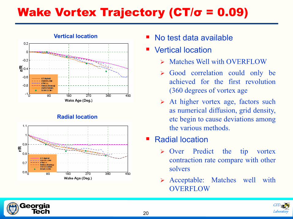
Vertical location ▪ No test data available
▪ Vertical location
➢ Matches Well with OVERFLOW
➢ Good correlation could only be
achieved for the first revolution
(360 degrees of vortex age
➢ At higher vortex age, factors such
as numerical diffusion, grid density,
etc begin to cause deviations among
the various methods.
▪ Radial location
➢ Over Predict the tip vortex
contraction rate compare with other
solvers
➢ Acceptable: Matches well with
OVERFLOW

21
S-76 Baseline Rotor
(Inflow is non-uniform)
Induced Velocity (at the Rotor Disk), at 9.5 Degrees Pitch Angle
r/R
vi/
RT
IP
0.4 0.6 0.8
-0.02
0
0.02
0.04
0.06
0.08
0.1
Azimuth (30 Deg.)_ST
Azimuth (60 Deg.)_ST
Azimuth (120 Deg.)_ST
Azimuth (150 Deg.)_ST
Azimuth (210 Deg.)_ST
Azimuth (240 Deg.)_ST
Azimuth (300 Deg.)_ST
Azimuth (330 Deg.)_ST
30 degrees upstream and downstream of the blade
At other stations
S-76 Baseline Rotor

22
Rotor with Anhedral Tip has a more uniform inflow
r/R
vi/
RT
IP
0.4 0.6 0.8 1
-0.06
-0.04
-0.02
0
0.02
0.04
0.06
0.08
Azimuth (30 Deg.)
Azimuth (60 Deg.)
Azimuth (120 Deg.)
Azimuth (150 Deg.)
Azimuth (210 Deg.)
Azimuth (240 Deg.)
Azimuth (300 Deg.)
Azimuth (330 Deg.)
30 degrees upstream and downstream of the blade
At other stations
Anhedral Tip
Induced Velocity (at the Rotor Disk), at 9.5 Degrees Pitch Angle

23
RESULTS AND DISCUSSION
FOR THE COAXIAL ROTOR

24
Harrington Rotor Characteristics
Blade Planform
Rotor Characteristics
Harrington “Rotor 1” Harrington “Rotor 2”
• Tested inside a full-scale wind tunnel at NACA Langley Research Center
• Reference: Harrington, R.D., “Full-Scale-Tunnel Investigation of the Static Thrust
Performance of a Coaxial Helicopter Rotor,” NACA TN 2318, Mar. 1951

25
Hover Performance

26
Contributions: Upper & Lower Rotor to Thrust

27
Upper vs Lower Rotor Figure of Merit

28
Effect of Number of Wake Filaments
29
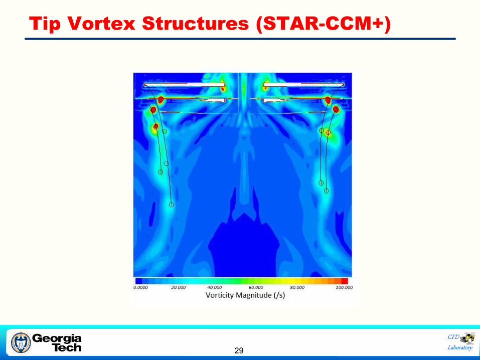
Tip Vortex Structures (STAR-CCM+)

30
Comparison of Tip Vortex Descent Rate

31
Comparison of Tip Vortex Contraction Rate

32
• The aerodynamic behavior of a conventional rotors,
anhedral rotors, and coaxial rotors has been studied
using two approaches – a hybrid Navier-Stokes-free
wake solver, and a full wake-capturing approach
• Comparisons with test data have been done.
• Anhedral tips produce a more uniform induced velocity.
• This leads to a more efficient rotor.
• Coaxial rotors are compact, have reduced swirl losses,
and eliminate the need for tail rotor.
• The performance of upper and lower rotors, for equal and
opposite torque, was examined
• Comparisons of the predicted vortex descent rate and radial
contraction rate were also examined
Summary

33
Conclusions
• At lower thrust settings, both methods give good
agreement with test data
• As the thrust level increases, the hybrid method tends to
underestimate the power required, and overestimate the
figure of merit
• We are in the process of improving the hybrid results using
vortex particle methods, improved tip cap grids, and
improved treatment of root regions

34
Conclusions (Continued)
• In terms of computational time, the hybrid method is very
efficient, requiring 4 to 6 hours of CPU time on a Linux
cluster with 72 cores of CPU
− The wake capturing method is considerably more expensive.
• For this reason, the hybrid method is well suited for initial
design studies where the rotor geometry is
parametrically varied, and quick reasonably accurate
solutions are essential
• Once a few promising configurations have been
identified, more accurate (but computationally
expensive) wake capturing simulations may be done to
refine the design.

35
Related Prior Work
❖ Hariharan, N., Egolf, T. A., and Sankar, L. N., “Simulation of Rotor in Hover:
Current State, Challenges and Standardized Evaluation,” AIAA 2014-0041.
❖ Lorber, P.F., et al., “A Comprehensive Hover Test of the Airloads and
Airflow of an Extensively Instrumented Model Helicopter Rotor,”
Proceedings of the 45th Annual Forum, American Helicopter Society, May
1989, pp 281-295.
❖ Balch, D. T., “Experimental Study of Main Rotor Tip Geometry and Tail
Rotor Interactions in Hover, Volume 2, Run Log and Tabulated Data,”
NASA CR 177336, 1985.
❖ Marpu, R., Sankar, L. N., Egolf, T. A., and Hariharan, N., “Simulation of S-
76 Rotor in Hover Using a Hybrid Methodology,” AIAA-2014-0210, SciTech
2014, January 2014.
❖ Baeder, J., Medida, S., “OVERTURNS Simulation of S-76 Rotor in Hover,”
AIAA-2014-0045, SciTech 2014, National Harbor, MD, January 2014.
Top Related