


Languages
Pages
Legal


Copeland™ Stream CO2Semi-Hermetic Compressors for Transcritical & Subcritical Applications4MTL-05_ to 4MTL-50_
Application Guidelines
4MSL-03_ to 4MSL-15_
AGL_Stream_ST_4MTL_4MSL_E_Rev01
About these guidelines ............................................................................................... 1
1 Safety instructions ........................................................................................... 1
1.1 Icon explanation ............................................................................................................... 1
1.2 Safety statements ............................................................................................................ 1
1.3 General instructions ......................................................................................................... 2
2 Product description ......................................................................................... 3
2.1 General information about Copeland™ Stream CO2 semi-hermetic compressors for transcritical and subcritical applications ................................................................................... 3
2.2 Nomenclature ................................................................................................................... 4
2.3 Nameplate information ..................................................................................................... 4
2.4 Application range ............................................................................................................. 5
2.4.1 Qualified refrigerant and oil .................................................................................. 5
2.4.2 Application limits ................................................................................................... 5
2.4.3 Recommendations for minimum suction superheat – Lubrication conditions ...... 6
2.5 Design features ................................................................................................................ 7
2.5.1 Compressor construction ..................................................................................... 7
2.5.2 Compressor cooling ............................................................................................. 7
2.5.3 Lubrication ............................................................................................................ 7
2.5.4 Oil level ................................................................................................................. 8
3 Installation ...................................................................................................... 11
3.1 Compressor handling ..................................................................................................... 11
3.1.1 Delivery............................................................................................................... 11
3.1.2 Transport and storage ........................................................................................ 11
3.1.3 Positioning and securing .................................................................................... 11
3.1.4 Installation location ............................................................................................. 12
3.1.5 Mounting parts .................................................................................................... 12
3.2 Pressure safety controls ................................................................................................ 13
3.2.1 Safety relief valves ............................................................................................. 13
3.2.2 Maximum allowable pressures PS ..................................................................... 14
3.2.3 Maximum operating pressures ........................................................................... 14
3.3 Shut-off valves ............................................................................................................... 14
3.3.1 Shut-off valves design ........................................................................................ 15
3.3.2 Explanation of supplier description .................................................................... 15
3.3.3 Additional information about shut-off valves ...................................................... 15
3.3.4 Variations for shut-off valves .............................................................................. 16
3.4 Screens .......................................................................................................................... 17
4 Electrical connection ..................................................................................... 18
4.1 General recommendations............................................................................................. 18
4.2 Electrical installation ...................................................................................................... 18
4.2.1 Part-winding motors (YY/Y) – Code A ................................................................ 18

AGL_Stream_ST_4MTL_4MSL_E_Rev01
4.2.2 Part-winding motors (YY/Y) – Code F ................................................................ 18
4.2.3 Star / Delta motors (Y/∆) – Code E .................................................................... 18
4.2.4 Terminal box isolators and jumpers position ...................................................... 19
4.3 Wiring diagrams ............................................................................................................. 20
4.3.1 Compressors with Next Generation CoreSense module ................................... 20
4.3.2 Compressors with CoreSense Protection module ............................................. 22
4.3.3 Compressors with CoreSense Diagnostics module ........................................... 24
4.4 Protection devices .......................................................................................................... 26
4.5 Next generation CoreSense™ ....................................................................................... 26
4.5.1 Next Gen CoreSense specifications .................................................................. 26
4.5.2 Next Gen CoreSense features ........................................................................... 26
4.6 CoreSense™ Protection ................................................................................................ 27
4.6.1 Motor protection ................................................................................................. 27
4.7 CoreSense™ Diagnostics (until December 2019 included) .......................................... 28
4.8 Crankcase heater ........................................................................................................... 29
5 Start-up & operation ....................................................................................... 31
5.1 Leak test......................................................................................................................... 31
5.2 System evacuation ......................................................................................................... 31
5.3 Preliminary checks – Pre-starting .................................................................................. 31
5.4 Charging procedure ....................................................................................................... 32
5.5 Initial start-up ................................................................................................................. 32
5.6 Minimum run time .......................................................................................................... 32
5.7 Inverter operation ........................................................................................................... 33
5.7.1 Maximum Operating Current – Models 4MTL-35 to 4MTL-50 ........................... 33
5.7.2 Recommendations for use with an inverter ........................................................ 33
6 Maintenance & repair ..................................................................................... 35
6.1 Exchanging the refrigerant ............................................................................................. 35
6.2 Replacing a compressor ................................................................................................ 35
6.3 Lubrication and oil removal ............................................................................................ 35
6.4 Oil additives ................................................................................................................... 36
6.5 Unbrazing system components ..................................................................................... 36
7 Dismantling & disposal .................................................................................. 36
Appendix 1: Connections of Stream CO2 compressors .......................................... 37
Appendix 2: Tightening torques in Nm .................................................................... 38
Appendix 3: Correct T-plate isolators depending on motor version & power supply ......................................................................................................................... 40
Disclaimer .................................................................................................................. 41

AGL_Stream_ST_4MTL_4MSL_E_Rev01 1
About these guidelines
The purpose of these application guidelines is to provide guidance in the application of Copeland™ Stream semi-hermetic compressors 4MTL* and 4MSL*. They are intended to answer the questions raised while designing, assembling and operating a system with these products.
Besides the support they provide, the instructions listed herein are also critical for the proper and safe functioning of the compressors. Emerson will not guarantee the performance and reliability of the product if it is misused in regard of these guidelines.
These application guidelines cover stationary applications only. For mobile applications, contact Application Engineering as other considerations may apply.
1 Safety instructions
Copeland™ semi-hermetic compressors are manufactured according to the latest European safety standards. Particular emphasis has been placed on the user’s safety.
These compressors are intended for installation in systems according to the Machinery Directive MD 2006/42/EC. They may be put to service only if they have been installed in these systems according to instructions and conform to the corresponding provisions of legislation. For relevant standards please refer to the Manufacturer’s Declaration, available at www.climate.emerson.com/en-gb.
These instructions should be retained throughout the lifetime of the compressor.
You are strongly advised to follow these safety instructions.
1.1 Icon explanation
WARNING This icon indicates instructions to avoid personal injury and material damage.
CAUTION This icon indicates instructions to avoid property damage and possible personal injury.
High voltage This icon indicates operations with a danger of electric shock.
IMPORTANT This icon indicates instructions to avoid malfunction of the compressor.
Danger of burning or frost burn This icon indicates operations with a danger of burning or frost burn.
NOTE
This word indicates a recommendation for easier operation.
Explosion hazard This icon indicates operations with a danger of explosion.
1.2 Safety statements
▪ Refrigerant compressors must be employed only for their intended use.
▪ Only qualified and authorized HVAC or refrigeration personnel are permitted to install, commission and maintain this equipment.
▪ Electrical connections must be made by qualified electrical personnel.
▪ All valid standards for connecting electrical and refrigeration equipment must be observed.
▪ The national legislation and regulations regarding personnel protection must be observed.
Use personal safety equipment. Safety goggles, gloves, protective clothing, safety boots and hard hats should be worn where necessary.

2 AGL_Stream_ST_4MTL_4MSL_E_Rev01
1.3 General instructions
WARNING System breakdown! Personal injuries! Never install a system in the field and leave it unattended when it has no charge, a holding charge, or with the service valves closed without electrically locking out the system. System breakdown! Personal injuries! Only approved refrigerants and refrigeration oils must be used.
WARNING CO2 refrigerant! Danger of suffocation! Never release significant volumes of CO2 or the entire contents of the system into closed rooms. In case of closed room, if possible, keep the room well ventilated and/or install a CO2 detection device. CO2 is odourless and colourless, so it cannot be perceived directly in case of emission.
WARNING High shell temperature! Burning! Do not touch the compressor until it has cooled down. Ensure that other materials in the area of the compressor do not get in touch with it. Lock and mark accessible sections.
CAUTION Overheating! Bearing damage! Do not operate compressor without refrigerant charge or without it being connected to the system.
CAUTION Contact with POE! Material damage! POE lubricant must be handled carefully and the proper protective equipment (gloves, eye protection, etc.) must be used at all times. POE must not come into contact with any surface or material that it might damage, including without limitation, certain polymers, eg, PVC/CPVC and polycarbonate.
IMPORTANT Transit damage! Compressor malfunction! Use original packaging. Avoid collisions and tilting.

AGL_Stream_ST_4MTL_4MSL_E_Rev01 3
2 Product description
2.1 General information about Copeland™ Stream CO2 semi-hermetic compressors for transcritical and subcritical applications
These guidelines cover Copeland™ Stream CO2 semi-hermetic compressors. The Stream CO2 series of 4MTL* transcritical models ranges from 5 to 50 hp; the series of 4MSL* subcritical models ranges from 3 to 15 hp. The performance values shown in Table 1 are valid for 50 Hz supply frequency.
Compressor Displacement
(m³/h) Cooling capacity
Qo* (kW) COP
Net weight (kg)
Footprint (mm x mm)
4MTL-05_ 4.6 8.831) 1.62
124
368 x 256
4MTL-07_ 6.2 11.851) 1.66
4MTL-09_ 7.4 14.591) 1.67
4MTL-12_ 9.5 19.241) 1.70
170 4MTL-15_ 12.5 25.161) 1.75
4MTL-30_ 17.9 36.991) 1.80
4MTL-35_ 22.7 46.901) 1.79
270 4MTL-40_ 26.6 55.901) 1.84
4MTL-50_ 32.0 67.801) 1.81
4MSL-03_ 4.6 7.802) 3.80
124 4MSL-04_ 6.2 10.402) 3.80
4MSL-06_ 7.4 12.802) 3.90
4MSL-08_ 9.5 16.302) 3.80
170 4MSL-12_ 12.5 20.702) 3.90
4MSL-15_ 17.9 31.502) 3.90 1) Evaporating -10 °C; gas cooler outlet temp 35 °C; high pressure 90 bar; superheat 10 K; subcooling 0 K 2) Evaporating -35 °C; condensing -5 °C; superheat 10 K; subcooling 0 K
Table 1: Stream CO2 compressors range and performance at full load (100 %)
Table 2 shows the key pressure values that are relevant to the use of Stream CO2 compressors.
Compressor Motor Maximum operating
pressure (MOP) (bar(a))
Standstill pressure (nameplate)
PS / PSS (bar(a))
Burst pressure (bar(a))
4MTL-05_ EWL FWM/D
FWE / FWC 120 / 50.9 135 / 90 420 / 287 4MTL-07_
4MTL-09_
4MTL-12_ AWM/D EWL AWE
120 / 50.9 135 / 90 420 / 287 4MTL-15_
4MTL-30_ 120 / 42
4MTL-35_ AWM EWL AWE
110 / 42 135 / 90 420 / 287 4MTL-40_
4MTL-50_
4MSL-03_ EWL FWM/D
FEW / FWC 60 / 23 135 / 90 420 / 287 4MSL-04_
4MSL-06_
4MSL-08_ AWM/D EWL AWE
60 / 23 135 / 90 420 / 287 4MSL-12_
4MSL-15_
Table 2: Stream CO2 compressor pressures
The line-up of 4-cylinder semi-hermetic Stream compressors for CO2 transcritical applications is the ideal solution for R744 medium temperature section of booster systems. This range is designed for

4 AGL_Stream_ST_4MTL_4MSL_E_Rev01
maximum standstill pressures of 135 bar at high side and 90 bar at low side – see Chapter 3.2.1 "Safety relief valves". Refrigerant flow and heat transfer have been optimized for best performance.
NOTE: Throughout these guidelines, pressure values shown with the bar(a) or bar unit are absolute pressures. For values in relative (gauge) pressure, bar(g) will be used.
NOTE: The compressor is only one component which must be combined with many others to build a functional and efficient refrigeration system. Therefore the information in this manual relates to Copeland Stream semi-hermetic compressors for CO2 transcritical and subcritical applications with standard equipment and accessories only.
2.2 Nomenclature
The model designation contains the following technical information about Stream CO2 compressors:
Figure 1: Nomenclature
* The oil type is indicated on the nameplate – see Chapter 2.3 "Nameplate information". Several oils are qualified – see Chapter 2.5.1 "Qualified refrigerant and oils".
2.3 Nameplate information
All important information for identification of the compressor is printed on the nameplate located below the left cylinder bank:
▪ the year and month of production are shown as part of the serial number (Jan = A, Feb = B, … Dec = L);
▪ type of refrigerant (R744);
▪ type of lubricant: POE or PAG.
Figure 2: Nameplate information
20C = Produced in March 2020
POE68 = Oil type
R744 = CO2 refrigerant

AGL_Stream_ST_4MTL_4MSL_E_Rev01 5
2.4 Application range
2.4.1 Qualified refrigerant and oil
Stream CO2 compressors are delivered with POE oil. Large models (4MTL-35 to 4MTL-50) can alternatively be delivered on request with PAG oil.
Oil recharge values can be taken from Copeland™ brand products Select software available at www.climate.emerson.com/en-gb.
Qualified refrigerant R744 (CO2)
Copeland brand products standard oils
Emkarate RL 68 HB (POE 68) Zerol RFL 68 EP (PAG 68)*
Qualified servicing oils Emkarate RL 68 HB (POE 68) Zerol RFL 68 EP (PAG 68)*
Factory oil charge (litres)
Medium temp
Low temp
Medium temp
Low temp
Medium temp
4MTL-05 4MTL-07 4MTL-09
4MSL-03 4MSL-04 4MSL-06
4MTL-12 4MTL-15 4MTL-30
4MSL-08 4MSL-12 4MSL-15
4MTL-35 4MTL-40 4MTL-50
1.3 1.8 2.5
* Optional and for large models only
Table 3: Qualified refrigerant and oils & factory oil charges
To recharge:
▪ When the compressor is completely empty of oil, the amount of oil to be "recharged" is typically 0.12 litre less than the original oil charge (oil will already be present in the system).
To top up:
▪ During commissioning, planned maintenance or servicing, add oil so that the compressor oil level is between min ¼ and max ¾ of side sight glasses and full in the housing cover sight glass.
▪ Recommended quality for carbon dioxide purity class: 4.0 [(≥ 99.99 %) H2O ≤ 10 ppm, O2 ≤ 10 ppm, N2 ≤ 50 ppm] or higher.
2.4.2 Application limits
WARNING Oil dilution due to low superheat! Compressor breakdown! Low suction superheat leads to oil dilution. Always operate the system with adequate superheat to avoid oil viscosity decrease. Additional measures in system design might help to avoid inacceptable lubrication conditions.
The operating envelopes of transcritical and subcritical StreamCO2 compressors are shown below.
Figure 3: Operating envelopes for transcritical applications with R744 – Models 4MTL-05 to 4MTL-15

6 AGL_Stream_ST_4MTL_4MSL_E_Rev01
Figure 4: Operating envelopes for transcritical applications with R744 – Models 4MTL-30 to 4MTL-50
Figure 5: Operating envelope for subcritical applications with R744 – Models 4MSL-03 to 4MSL-15
2.4.3 Recommendations for minimum suction superheat – Lubrication conditions
The operation of CO2 compressors at conditions where the viscosity of the oil is low might become very harmful with regard to compressor lifetime expectancy. Indicators like oil temperature and discharge temperature must be observed to judge about the lubrication conditions. Depending on the application (low temp, medium temp, parallel compression, etc.) different minimum suction superheat values have to be respected to secure maximum protection of the compressor. In general, higher superheat on the suction inlet of a compressor provides higher safety, but the limits for the maximum allowable discharge temperature have to be considered as well (superheat has a direct impact on the discharge temperature).
Particular attention should be paid to the following points:
▪ Measuring the suction superheat becomes more critical with larger diameters on the suction tube. Ensure proper positioning of sensor. Sensor sleeves must be used with large diameters.
▪ The oil temperature is measured on the bottom (lowest position) of the compressor shell directly between the two sight glasses. The use of sensors for measurements on a plain surface is preferable for best accuracy.
▪ The discharge temperature can be read through Modbus from the CoreSense Diagnostics module. If an additional sensor is applied to the discharge line (as close as possible to the

AGL_Stream_ST_4MTL_4MSL_E_Rev01 7
discharge shut-off valve) the temperature is expected to be 15-20 K lower than inside the cylinder head. This fact must be taken into account when applying the values in Table 4 below.
Application Minimum superheat required
Minimum oil temperature
required
Maximum acceptable discharge temperature
Stream Scroll
Low temp 20 K / 36 °F 30 °C / 86 °F 154.4 °C / 310 °F 121.1 °C / 250 °F
Medium temp 10 K / 18 °F 30 °C / 86 °F 154.4 °C / 310 °F N/A
Compressors in parallel or multi-compressors
10 K / 18 °F 30 °C / 86 °F 154.4 °C / 310 °F N/A
Table 4: Superheat recommendations
Attention! The values shown in Table 4 are maximum temperature values inside the cylinder head. When using a discharge temperature sensor on the discharge line, the temperature drop has to be considered for the high DLT cut-out setpoint.
NOTE: An additional internal heat exchanger might be required to ensure the recommended suction superheat values on the compressor inlet are achieved.
2.5 Design features
2.5.1 Compressor construction
Stream CO2 compressors have a large discharge chamber to eliminate pulsations. The cylinder heads and the discharge plenum are designed to minimize the heat transfer to suction side.
Each cylinder head has a plugged 1/8" - 27 NPTF tapped hole on the high pressure.
Figure 6: Compressor external view
2.5.2 Compressor cooling
Compressor motor cooling must be ensured in all circumstances.
All Stream CO2 compressors are suction gas-cooled. With suction gas-cooled compressors, the motor is cooled by refrigerant gas that is led through / over the motor. Depending upon the operating conditions, the maximum allowed suction gas superheat shall not exceed the values shown in the envelopes.
2.5.3 Lubrication
For small- and medium-size Stream CO2 compressors (4MSL-03 to 4MSL-15, 4MTL-05 to 4MTL-30), an oil splasher system ensures proper lubrication at constant or variable speed.
For large models (4MTL-35 to 4MTL-50) an oil pump is used:
▪ On compressors with Next Generation CoreSense™ (-N) or formerly delivered with CoreSense™ Diagnostics (-D), the oil pump integrates an electronic switch to ensure the oil pressure safety functionality.
▪ Compressors with CoreSense™ Protection (-P) are designed to accommodate fittings for an OPS2 or a standard oil pressure switch (OPS2 oil sensor included in the oil pump).
▪ The oil pumps used on these compressors are independent of their rotating direction.
8 AGL_Stream_ST_4MTL_4MSL_E_Rev01
Compressor size
Transcritical mode
Lubrication system
Subcritical mode
Lubrication system
Small
4MTL-05
Splasher
4MSL-03
Splasher 4MTL-07 4MSL-04
4MTL-09 4MSL-06
Medium
4MTL-12
Splasher
4MSL-08
Splasher 4MTL-15 4MSL-12
4MTL-30 4MSL-15
Large
4MTL-35
Oil pump - - 4MTL-40
4MTL-50
Table 5: Lubrication system on Stream CO2 compressors
2.5.4 Oil level
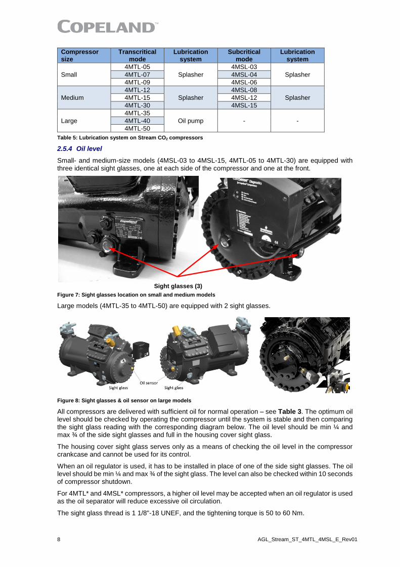
Small- and medium-size models (4MSL-03 to 4MSL-15, 4MTL-05 to 4MTL-30) are equipped with three identical sight glasses, one at each side of the compressor and one at the front.
Sight glasses (3)
Figure 7: Sight glasses location on small and medium models
Large models (4MTL-35 to 4MTL-50) are equipped with 2 sight glasses.
Figure 8: Sight glasses & oil sensor on large models
All compressors are delivered with sufficient oil for normal operation – see Table 3. The optimum oil level should be checked by operating the compressor until the system is stable and then comparing the sight glass reading with the corresponding diagram below. The oil level should be min ¼ and max ¾ of the side sight glasses and full in the housing cover sight glass.
The housing cover sight glass serves only as a means of checking the oil level in the compressor crankcase and cannot be used for its control.
When an oil regulator is used, it has to be installed in place of one of the side sight glasses. The oil level should be min ¼ and max ¾ of the sight glass. The level can also be checked within 10 seconds of compressor shutdown.
For 4MTL* and 4MSL* compressors, a higher oil level may be accepted when an oil regulator is used as the oil separator will reduce excessive oil circulation.
The sight glass thread is 1 1/8"-18 UNEF, and the tightening torque is 50 to 60 Nm.

AGL_Stream_ST_4MTL_4MSL_E_Rev01 9
Figure 9: Sight glass design Figure 10: Sight glass reading
For small- and medium-size compressors, as they do not have an oil pump, an oil pressure safety control cannot be used to protect the compressor against lubrication problems. However, a float level switch for oil can be used to protect the compressor against oil loss.
2.5.4.1 Oil level management device OM5 TraxOil
Active oil level management is a must in order to ensure reliable compressor operation, in particular in refrigeration applications with varying operating conditions and defrost cycles. An additional benefit of active systems is that, in addition to oil balancing, they normally also monitor the oil level and provide alarm capabilities.
Maintaining proper oil level is of primary importance for a long compressor lifetime.
The OM5 TraxOil uses a Hall effect sensor to measure the oil level. A magnetic float changes its position according to the oil level. The Hall sensor converts the magnetic field changes into an equivalent signal, which is used by the internal integrated electronics to evaluate the oil level.
The OM5 TraxOil provides both an oil level monitoring function and an oil level balancing function for active oil level management systems, especially in CO2 applications.
The OM5 TraxOil has been developed and specially optimized for CO2 systems where maximum working pressures above 60 bar and up to 130 bar are required.
The OM5 TraxOil is designed to feed oil in subcritical or transcritical CO2 compressors when necessary.
The oil level control is divided into 3 zones: normal, warning and alarm.
More information about this product can be found at www.climate.emerson.com/en-gb.
2.5.4.2 Oil level monitoring system OW4/OW5 TraxOil
The OW4 and OW5 TraxOil are intended for systems which only require oil level monitoring and alarming and do not need active oil level balancing.
▪ OW4 is designed for CO2 subcritical applications
▪ OW5 is designed for CO2 transcritical applications
Figure 12: OW4/OW5 TraxOil for oil level monitoring
The level control is divided into 3 zones: normal, warning and alarm.
Figure 11: TraxOil OM5 with sight glass & coil

10 AGL_Stream_ST_4MTL_4MSL_E_Rev01
If the oil level drops into the red zone, the OW4/OW5 generates an alarm signal and the alarm contact (SPDT) changes into alarm state. The alarm contact may be used to shut down the compressor. The alarm will be reset when the oil level goes back to normal.
More information about this product can be found at www.climate.emerson.com/en-gb.

AGL_Stream_ST_4MTL_4MSL_E_Rev01 11
3 Installation
WARNING High pressure! Injury to skin and eyes possible! Be careful when opening connections on a pressurized item.
3.1 Compressor handling
3.1.1 Delivery
Please check whether the delivery is correct and complete. Any deficiency should be reported immediately in writing.
Standard delivery:
▪ Suction and discharge shut-off valves
▪ Pressure relief valve on discharge
▪ Oil charge, oil sight glasses
▪ Crankcase heater 230 V
▪ Mounting parts kit (rubber)
▪ Next Generation CoreSense™, CoreSense™ Diagnostics or CoreSense™ Protection module
▪ Holding charge up to 2.5 bar(g) (dry air)
▪ Electrical terminals
3.1.2 Transport and storage
WARNING Risk of collapse! Personal injuries! Move compressors only with appropriate mechanical or handling equipment according to weight. Keep in the upright position. Respect stacking loads according to Figure 13. Check the tilting stability and if needed take action to ensure the stability of the stacked loads. Keep the packaging dry at all times.
Respect the maximum number of identical packages which may be stacked on one another, where "n" is the limiting number:
▪ Transport: n = 1 ▪ Storage: n = 1
Figure 13: Maximum stacking loads for transport and storage
NOTE: The compressor is pre-charged with dry air to avoid any moisture contamination.
Compressors are delivered on pallets. Accessories may be mounted or delivered loose.
3.1.3 Positioning and securing
IMPORTANT Handling damage! Compressor malfunction! Only use the lifting eyes whenever the compressor requires positioning. Using discharge or suction connections for lifting may cause damage or leaks.
If possible, the compressor should be kept horizontal during handling.
For safety reasons two lifting eyes should be fitted before moving a compressor (½" - 13 UNC, ident number 2932854). Otherwise refer to drawing in Figure 14 to see how to apply another lifting method.
In order to avoid refrigerant leaks or other damage the compressors should never be lifted by the service valves or other accessories.
12 AGL_Stream_ST_4MTL_4MSL_E_Rev01
Figure 14: Compressor lifting
3.1.4 Installation location
Ensure the compressors are installed on a solid level base. Horizontal installation is recommended.
Temperatures around the compressor should not exceed 65 °C in order to avoid suction gas temperature increase and malfunctioning of electronics.
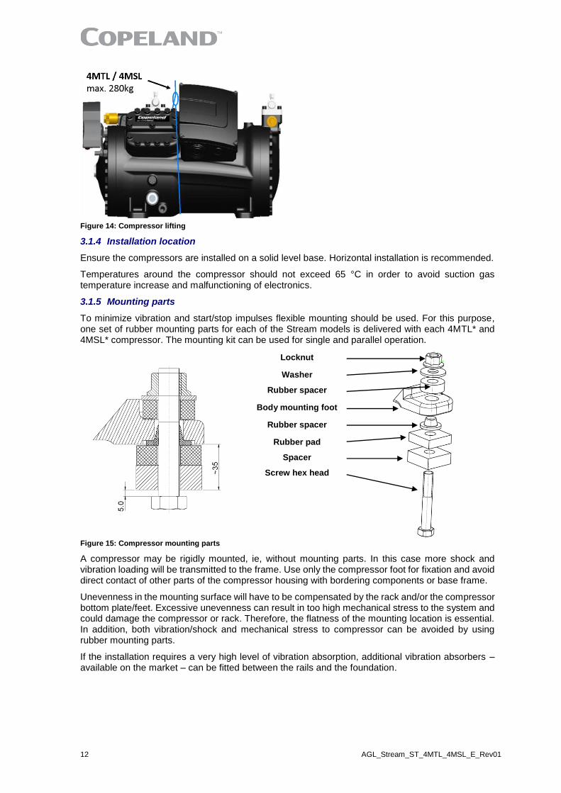
3.1.5 Mounting parts
To minimize vibration and start/stop impulses flexible mounting should be used. For this purpose, one set of rubber mounting parts for each of the Stream models is delivered with each 4MTL* and 4MSL* compressor. The mounting kit can be used for single and parallel operation.
Figure 15: Compressor mounting parts
A compressor may be rigidly mounted, ie, without mounting parts. In this case more shock and vibration loading will be transmitted to the frame. Use only the compressor foot for fixation and avoid direct contact of other parts of the compressor housing with bordering components or base frame.
Unevenness in the mounting surface will have to be compensated by the rack and/or the compressor bottom plate/feet. Excessive unevenness can result in too high mechanical stress to the system and could damage the compressor or rack. Therefore, the flatness of the mounting location is essential. In addition, both vibration/shock and mechanical stress to compressor can be avoided by using rubber mounting parts.
If the installation requires a very high level of vibration absorption, additional vibration absorbers – available on the market – can be fitted between the rails and the foundation.
Locknut
Washer
Rubber spacer
Body mounting foot
Rubber spacer
Rubber pad
Spacer
Screw hex head
AGL_Stream_ST_4MTL_4MSL_E_Rev01 13
3.2 Pressure safety controls
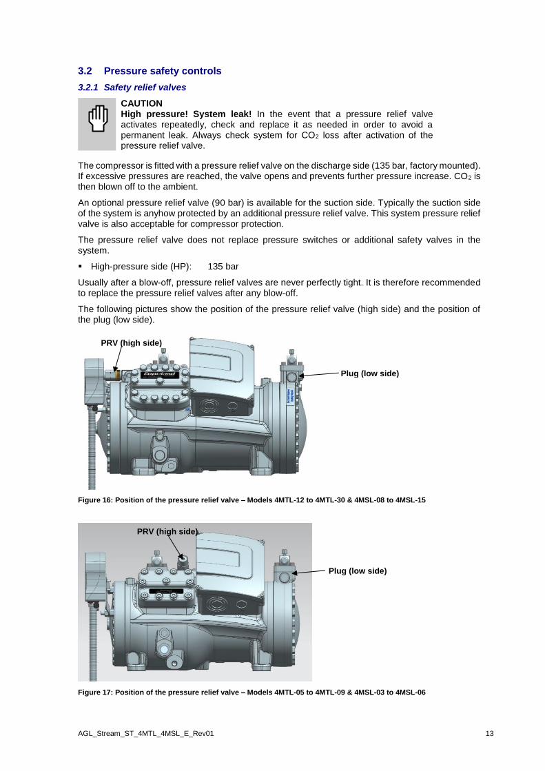
3.2.1 Safety relief valves
CAUTION High pressure! System leak! In the event that a pressure relief valve activates repeatedly, check and replace it as needed in order to avoid a permanent leak. Always check system for CO2 loss after activation of the pressure relief valve.
The compressor is fitted with a pressure relief valve on the discharge side (135 bar, factory mounted). If excessive pressures are reached, the valve opens and prevents further pressure increase. CO2 is then blown off to the ambient.
An optional pressure relief valve (90 bar) is available for the suction side. Typically the suction side of the system is anyhow protected by an additional pressure relief valve. This system pressure relief valve is also acceptable for compressor protection.
The pressure relief valve does not replace pressure switches or additional safety valves in the system.
▪ High-pressure side (HP): 135 bar
Usually after a blow-off, pressure relief valves are never perfectly tight. It is therefore recommended to replace the pressure relief valves after any blow-off.
The following pictures show the position of the pressure relief valve (high side) and the position of the plug (low side).
Figure 16: Position of the pressure relief valve – Models 4MTL-12 to 4MTL-30 & 4MSL-08 to 4MSL-15
Figure 17: Position of the pressure relief valve – Models 4MTL-05 to 4MTL-09 & 4MSL-03 to 4MSL-06
PRV (high side)
PRV (high side)
Plug (low side)
Plug (low side)
14 AGL_Stream_ST_4MTL_4MSL_E_Rev01
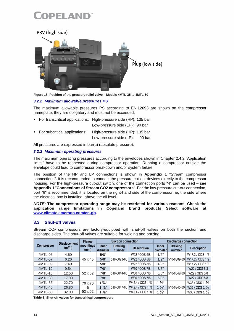
Figure 18: Position of the pressure relief valve – Models 4MTL-35 to 4MTL-50
3.2.2 Maximum allowable pressures PS
The maximum allowable pressures PS according to EN 12693 are shown on the compressor nameplate; they are obligatory and must not be exceeded.
▪ For transcritical applications: High-pressure side (HP): 135 bar
Low-pressure side (LP): 90 bar
▪ For subcritical applications: High-pressure side (HP): 135 bar
Low-pressure side (LP): 90 bar
All pressures are expressed in bar(a) (absolute pressure).
3.2.3 Maximum operating pressures
The maximum operating pressures according to the envelopes shown in Chapter 2.4.2 "Application limits" have to be respected during compressor operation. Running a compressor outside the envelope could lead to compressor breakdown and/or system failure.
The position of the HP and LP connections is shown in Appendix 1 "Stream compressor connections". It is recommended to connect the pressure cut-out devices directly to the compressor housing. For the high-pressure cut-out switch, one of the connection ports "4" can be used – see Appendix 1 "Connections of Stream CO2 compressors". For the low-pressure cut-out connection, port "6" is recommended; it is located on the right-hand side of the compressor, ie, the side where the electrical box is installed, above the oil level.
NOTE: The compressor operating range may be restricted for various reasons. Check the application range limitations in Copeland brand products Select software at www.climate.emerson.com/en-gb.
3.3 Shut-off valves
Stream CO2 compressors are factory-equipped with shut-off valves on both the suction and discharge sides. The shut-off valves are suitable for welding and brazing.
Compressor Displacement
(m³/h)
Flange mountings
(mm)
Suction connection Discharge connection
Inner diameter
Drawing number
Description Inner
diameter Drawing number
Description
4MTL-05 4.60
45 x 45
5/8"
510-0823-00
W22 / ODS 5/8 1/2"
510-0809-00
W17.2 / ODS 1/2
4MTL-07 6.20 5/8" W22 / ODS 5/8 1/2" W17.2 / ODS 1/2
4MTL-09 7.40 5/8" W22 / ODS 5/8 1/2" W17.2 / ODS 1/2
4MTL-12 9.54
52 x 52
7/8"
510-0844-00
W30 / ODS 7/8 5/8"
510-0842-00
W22 / ODS 5/8
4MTL-15 12.50 7/8" W30 / ODS 7/8 5/8" W22 / ODS 5/8
4MTL-30 17.90 7/8" W30 / ODS 7/8 5/8" W22 / ODS 5/8
4MTL-35 22.70 70 x 70 &
52 x 52
1 ⅜"
510-0847-00
W42.4 / ODS 1 ⅜ 1 ⅛"
510-0845-00
W35 / ODS 1 ⅛
4MTL-40 26.80 1 ⅜" W42.4 / ODS 1 ⅜ 1 ⅛" W35 / ODS 1 ⅛
4MTL-50 32.00 1 ⅜" W42.4 / ODS 1 ⅜ 1 ⅛" W35 / ODS 1 ⅛
Table 6: Shut-off valves for transcritical compressors

AGL_Stream_ST_4MTL_4MSL_E_Rev01 15
Compressor Displacement
(m³/h)
Flange mountings
(mm)
Suction connection Discharge connection
Inner diameter
Drawing number
Description Inner
diameter Drawing number
Description
4MSL-03 4.60
45 x 45
5/8"
510-0823-00
W22 / ODS 5/8 1/2"
510-0809-00
W17.2 / ODS 1/2
4MSL-04 6.20 5/8" W22 / ODS 5/8 1/2" W17.2 / ODS 1/2
4MSL-06 7.40 5/8" W22 / ODS 5/8 1/2" W17.2 / ODS 1/2
4MSL-08 9.54
52 x 52
7/8"
510-0844-00
W30 / ODS 7/8 5/8"
510-0842-00
W22 / ODS 5/8
4MSL-12 12.50 7/8" W30 / ODS 7/8 5/8" W22 / ODS 5/8
4MSL-15 17.90 7/8" W30 / ODS 7/8 5/8" W22 / ODS 5/8
Table 7: Shut-off valves for subcritical compressors
3.3.1 Shut-off valves design
The standard shut-off valves on Stream CO2 compressors are flange valves with one flare connection port (lockable) for service. The service connection port is a 7/16" – 20 UNF, with a blind cap SAE 1/4" (blind cap material: stainless steel 1.4301). The valves are universal, ie, suitable for brazing or welding (butt weld and fillet weld connections are possible).
Figure 19: 3-D view of shut-off valve
For proper tightening torques for bolts, spindle cap, blind cap and gland seal, please refer to table in Appendix 2 "Tightening torques in Nm".
The spindle is front-seated (close to piping system) when the compressor is delivered.
3.3.2 Explanation of supplier description
W 13.5 / ODS 3/8"
Outer diameter tube for brazing
Brazing
Outer diameter tube for welding
Welding
3.3.3 Additional information about shut-off valves
CAUTION High operating pressures! Risk of leakage! High operating pressures must be taken into account when welding and brazing connections. Use materials and follow procedures according to the relevant standards in order to prevent any risk of leakage when operating the compressor.
The shut-off valves are made of a fine-grained mild steel (S235JRG2C – EN 10025) suitable for both welding and brazing. Plating is Fe/Cu5Sn5 material.
The use of standard steel tubes (S235, P235, etc.) is possible.
When using stainless steel tubes (SS) the welding consumable has to be selected for dissimilar materials (stainless steel to mild steel).
For the brazing of the connection, brazing material with a minimum silver content of 34 % (or higher) in combination with flux material is required, eg, Fontargen A319, A320. The description of the brazing material according to European standard EN 1044 is AG106 and AG104 respectively.
In any case the connection area after welding or brazing has to be cleaned and protected against corrosion.

16 AGL_Stream_ST_4MTL_4MSL_E_Rev01
Valve description
Mounting dimensions
(F) (mm)
Inner Ø brazing
(d) (inch)
Thickness (Z)
(mm)
Dimension (a)
(mm)
Outer Ø butt welding
(D) (mm)
Depth for tube insertion
(h) (mm) PCN
W17.2 / ODS 1/2 45 x 45 1/2" 2.20 3.11 17.2 11.0
W22 / ODS 5/8 45 x 45 5/8" 2.95 4.17 22.0 11.0
W22 / ODS 5/8 52 x 52 5/8" 2.95 4.17 22.0 11.0
W30 / ODS 7/8 52 x 52 7/8" 3.83 5.41 30.0 16.0
W35 / ODS 1 ⅛ 52 x 52 1 ⅛" 3.15 4.45 35.0 19.0
W42.4 / ODS 1 ⅜ 70 x 70 1 ⅜" 4.20 5.94 42.4 23.0
Table 8: Dimensions for welding and brazing
Figure 20: Dimension references for welding and brazing
3.3.4 Variations for shut-off valves
Compressors can be ordered without valves on request. In that case the valves will be removed and a blind flange with gasket will be used for suction and discharge to guarantee the tightness of the compressor during transport.
For Stream CO2 compressors, Emerson also offers variations for connection sizes – see Tables 9 & 10 below for details. Additionally, a compression fitting can be used for the discharge part of the compressors. Compressors can be ordered with "variation discharge shut-off valve with Hy-Lok fitting at the discharge part". The tube diameter for the discharge line must be defined by the customer.
Variation bigger Ø
Compressor Displ. (m³/h)
Flange Mountings
(mm)
Suction connection Discharge connection
Transcritical Subcritical Inner Ø brazing
Valve description
Inner Ø brazing
Valve description
4MTL-05 4MSL-03 4.60
45 x 45 3/4" W25.4 / ODS 3/4
5/8" W22 /
ODS 5/8 4MTL-07 4MSL-04 6.20
4MTL-09 4MSL-06 7.40
4MTL-12 4MSL-08 9.54
52 x 52 1 ⅛" W35 /
ODS 1 ⅛ 3/4"
W25.4 / ODS 3/4
4MTL-15 4MSL-12 12.50
4MTL-30 4MSL-15 17.90
4MTL-35 --- 22.70 70 x 70
& 52 x 52
1 ⅝" W48.3 /
ODS 1 ⅝ Not available 4MTL-40 --- 26.80
4MTL-50 --- 32.00
Table 9: Variations with larger tube connections
F

AGL_Stream_ST_4MTL_4MSL_E_Rev01 17
Variation smaller Ø
Compressor Displ. (m³/h)
Flange Mountings
(mm)
Suction connection Discharge connection
Transcritical Subcritical Inner Ø brazing
Valve description
Inner Ø brazing
Valve description
4MTL-05 4MSL-03 4.60
45 x 45 1/2" W17.2 / ODS 1/2
1/2" W17.2 / ODS 1/2
4MTL-07 4MSL-04 6.20
4MTL-09 4MSL-06 7.40
4MTL-12 4MSL-08 9.54
52 x 52 5/8" W22 /
ODS 5/8 1/2"
W17.2 / ODS 1/2
4MTL-15 4MSL-12 12.50
4MTL-30 4MSL-15 17.90
4MTL-35 --- 22.70 70 x 70
& 52 x 52
1 ⅛" W35 /
ODS 1 ⅛" 7/8"
W30 / ODS 7/8
4MTL-40 --- 26.80
4MTL-50 --- 32.00
Table 10: Variations with smaller tube connections
3.4 Screens
CAUTION Screen blocking! Compressor breakdown! Use screens with at least 0.6 mm openings.
The use of screens finer than 30 x 30 meshes (0.6 mm openings) anywhere in the system should be avoided with these compressors. Field experience has shown that finer mesh screens used to protect thermal expansion valves, capillary tubes or accumulators can become temporarily or permanently plugged with normal system debris and block the flow of either oil or refrigerant to the compressor. Such blockage can result in compressor failure.

18 AGL_Stream_ST_4MTL_4MSL_E_Rev01
4 Electrical connection
4.1 General recommendations
The compressor terminal box has a wiring diagram on the inside of its cover. Before connecting the compressor, ensure that the supply voltage, the phases and the frequency match the nameplate data.
The knockouts have to be removed before the electrical glands can be installed. First make sure that the terminal box is closed with the terminal box cover. We recommend to use a subland twist driller to avoid any damage to the box while removing the knockouts.
Figure 21: Terminal box knockouts
4.2 Electrical installation
All compressors can be started Direct-On-Line.
The position of bridges required for Direct-On-Line start (depending on the type of motor and/or mains voltage) is shown in paragraph 4.2.4 "Terminal box isolators and jumper position".
4.2.1 Part-winding motors (YY/Y) – Code A
A part-winding motor contains two separate windings (2/3 + 1/3) which are internally connected in star and operated in parallel. The voltage cannot be modified by changing the electrical connections as the motor is only suitable for one voltage.
The first part-winding, ie, the 2/3 winding on terminals 1-2-3, can be used for part-winding start (remove the bridges!). After a time delay of 1 ± 0.1 seconds the second part-winding, ie, the 1/3 winding on terminals 7-8-9, must be brought on line.
4.2.2 Part-winding motors (YY/Y) – Code F
Part-winding motors contain two separate windings (Code F motors always split by 1/2 + 1/2) which are internally connected in star and operated in parallel. The voltage cannot be modified by changing the electrical connections as the motor is only suitable for one voltage.
The first part-winding, ie, the 1/2 winding on terminals 1-2-3, can be used for part-winding start (remove the bridges!). After a time delay of 1 ± 0.1 seconds the second part-winding, ie, the second half winding on terminals 7-8-9, must be brought on line.
4.2.3 Star / Delta motors (Y/∆) – Code E
On this three-phase motor, the 6 ends of the three windings are led into the terminal box of the compressor via cable bushings.
The star or delta connection as required is achieved by means of connection bars in the terminal box or via controlled contactors. Thus, the motor can be run at the operating voltage.
The voltage version L (motor code EWL) of this motor allows operation at two voltages, a lower voltage, eg, 230 V in delta connection, and a higher voltage, eg, 400 V in star connection.
The voltage version M or D (motor code EWM for 50 Hz or EWD for 60 Hz) of this motor shall be used for full-load in delta connection. Here the star connection is used primarily for starting (Star / Delta start).
However, the EWM motor can also be used for power supply with voltages of 690 V / 3 Ph / 50 Hz in star connection (only on the M version).
Twist driller

AGL_Stream_ST_4MTL_4MSL_E_Rev01 19
4.2.4 Terminal box isolators and jumpers position
4.2.4.1 Part-winding motors (AW… or FW…)
Part-winding motors can be connected Direct-On-Line or part-winding start.
Make sure that the 2 wires (L2) which are guided through the current sensor are in the same direction. The black wire (voltage sensing) from the sensor module must be connected to the same terminal as the wires that are guided through the current sensor.
Part-winding motor: YY – Y Code A Code F
Direct-On-Line start YY - Y
Part-winding start YY – Y First start step 1–2-3
Recommended isolator
(packed in T-Box)
Figure 22: Terminal box isolators & jumpers position for part-winding motors
NOTE: The isolators are not factory-mounted; they are packed and shipped loose in the terminal box.
NOTE: Assembly instructions with an exploded view are provided in Appendix 3.
4.2.4.2 Star/Delta motors (EW…)
Star/Delta motors can be connected Direct-On-Line or Star/Delta start.
Star/Delta motor Y - ∆
Code E
Direct-On-Line start ∆
Direct-On-Line start Y
Star/Delta start Y - ∆
Recommended isolator
(packed in T-Box)
Figure 23: Terminal box isolators & jumpers position for Star/Delta motors
NOTE: The isolators are not factory-mounted; they are packed and shipped loose in the terminal box.
NOTE: Assembly instructions with an exploded view are provided in Appendix 3.

20 AGL_Stream_ST_4MTL_4MSL_E_Rev01
4.3 Wiring diagrams
4.3.1 Compressors with Next Generation CoreSense module
IMPORTANT For small and medium compressor models (4MTL-05 to 4MTL-30 & 4MSL-03 to 4MSL-15), the blue positions 1U, 2V, 3W, 7Z, 8X, 9Y in diagrams below must be considered. The position of the terminals in large models (4MTL-35 to 4MTL-50) is inverted and corresponds to the black positions. The factory delivery is correct, DO NOT reverse the connections.
4.3.1.1 Wiring diagram (1st part) for part-winding motors (AW…, FW…)
Figure 24: Wiring diagram – Part-winding motors (AW…, FW…)
4.3.1.2 Wiring diagram (1st part) for Star/Delta motors (EW…)
Figure 25: Wiring diagram – Star/Delta motors (EW…)

AGL_Stream_ST_4MTL_4MSL_E_Rev01 21
4.3.1.3 Wiring diagram (2nd part) for part-winding and Star/Delta motors (AW… & EW…)
Legend
B1 ........... Discharge gas sensor DGT .. Discharge gas temperature monitoring B2 ........... Oil level watch (TraxOil) OW .... Digital oil level watch B3 ........... Oil differential pressure switch (OPS) OPS .. Oil differential pressure protection B11 ......... High-pressure switch AR ..... Alarm relay B12 ......... Low-pressure switch DS ..... Demand signal CTR2 ...... DP Gateway E1 ........... Heater CH ..... Control oil heater F1,F2,F3 Compressor fuses PTC ... Motor thermal protection F4, F5 ..... Fan fuses PM ..... Phase monitoring F6 ........... CoreSense and heater fuse PS ..... Power supply F7 ........... Control circuit fuse H1 ........... Diagnosis LED K11 ......... Time relay for part-winding (if used) M2 .......... Fan motor Q11 ........ Compressor contactor Q15 ... Fan contactor Q12 ........ Compressor contactor Y (if Y/Δ start) Q13 ... Compressor contactor Δ (if Y/Δ start) Q14 ........ Compressor contactor 2nd part-winding (if used) SB1 ........ Reset button Y21 ......... Solenoid valve capacity control 1 (not used) Y22 ......... Solenoid valve capacity control 2 (not used) T1 ........... Current sensor CM ...... Current monitoring
Figure 26: Wiring diagram – Part-winding and Star/Delta motors (AW… & EW…)

22 AGL_Stream_ST_4MTL_4MSL_E_Rev01
4.3.2 Compressors with CoreSense Protection module
4.3.2.1 Wiring diagram for part-winding motors (AW…, FW…)
Legend
A1 ....... CoreSense Protection module K1 ........ Contactor M1 A5 ....... Terminal box compressor K4 ........ Contactor M1 for 2nd part-winding F6 ....... Fuse for control circuit M21 ..... Fan motor / condenser F7 ....... Fuse for control circuit R2 ........ Crankcase heater F8 ....... Fuse for control circuit S1 ........ Thermistor chain motor temperature F10 ..... Thermal protection switch M21 S2 ........ Thermistor chain motor temperature Y3 ........ Solenoid valve unloaded start
Figure 27: Wiring diagram – Part-winding motors (AW…, FW…) with CoreSense Protection
AGL_Stream_ST_4MTL_4MSL_E_Rev01 23
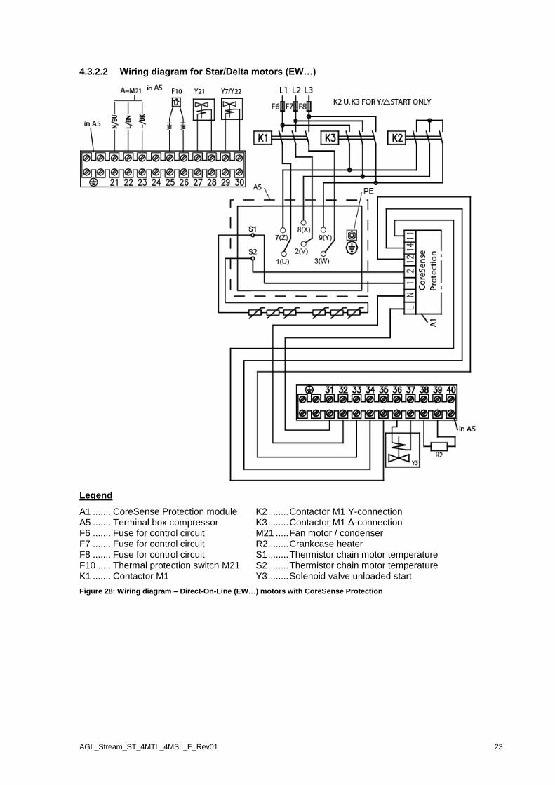
4.3.2.2 Wiring diagram for Star/Delta motors (EW…)
Legend
A1 ....... CoreSense Protection module K2 ........ Contactor M1 Y-connection A5 ....... Terminal box compressor K3 ........ Contactor M1 Δ-connection F6 ....... Fuse for control circuit M21 ..... Fan motor / condenser F7 ....... Fuse for control circuit R2 ........ Crankcase heater F8 ....... Fuse for control circuit S1 ........ Thermistor chain motor temperature F10 ..... Thermal protection switch M21 S2 ........ Thermistor chain motor temperature K1 ....... Contactor M1 Y3 ........ Solenoid valve unloaded start
Figure 28: Wiring diagram – Direct-On-Line (EW…) motors with CoreSense Protection
24 AGL_Stream_ST_4MTL_4MSL_E_Rev01
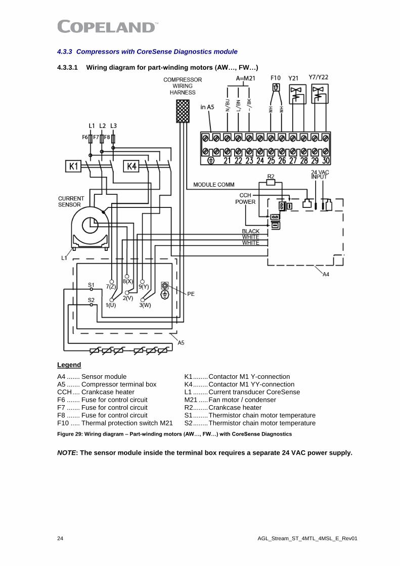
4.3.3 Compressors with CoreSense Diagnostics module
4.3.3.1 Wiring diagram for part-winding motors (AW…, FW…)
Legend
A4 ....... Sensor module K1 ........ Contactor M1 Y-connection A5 ....... Compressor terminal box K4 ........ Contactor M1 YY-connection CCH .... Crankcase heater L1 ........ Current transducer CoreSense F6 ....... Fuse for control circuit M21 ..... Fan motor / condenser F7 ....... Fuse for control circuit R2 ........ Crankcase heater F8 ....... Fuse for control circuit S1 ........ Thermistor chain motor temperature F10 ..... Thermal protection switch M21 S2 ........ Thermistor chain motor temperature
Figure 29: Wiring diagram – Part-winding motors (AW…, FW…) with CoreSense Diagnostics
NOTE: The sensor module inside the terminal box requires a separate 24 VAC power supply.

AGL_Stream_ST_4MTL_4MSL_E_Rev01 25
4.3.3.2 Wiring diagrams for Star/Delta motors (EW…)
Legend
A4 ....... Sensor module L1 ........ Current transducer CoreSense A5 ....... Compressor terminal box M21 ..... Fan motor / condenser F6 ....... Fuse for control circuit R2 ........ Crankcase heater F7 ....... Fuse for control circuit Y7 ........ Solenoid valve pumpdown F8 ....... Fuse for control circuit Y21 ...... Solenoid valve F10 ..... Thermal protection switch M21 Y22 ...... Solenoid valve K1 ....... Contactor M1 S1 ........ Thermistor chain motor temperature K2 ....... Contactor M1 Y-connection S2 ........ Thermistor chain motor temperature K3 ....... Contactor M1 Δ-connection
Figure 30: Wiring diagram – Direct-On-Line (EW…) motors with CoreSense Diagnostics
NOTE: The sensor module inside the terminal box requires a separate 24 VAC power supply.

26 AGL_Stream_ST_4MTL_4MSL_E_Rev01
4.4 Protection devices
Independently from the internal motor protection, fuses must be installed before the compressor. The selection of fuses has to made according to VDE 0635, DIN 57635, IEC 269-1 or EN 60-269-1.
4.5 Next generation CoreSense™
Next Generation CoreSense™ (or Next Gen CoreSense) is standard in all 4MTL* and 4MSL* Stream semi-hermetic compressors. With active protection, advanced algorithms and features like fault history and LED indicators, Next Gen CoreSense enables technicians to diagnose the past and recent state of the system, allowing for quicker, more accurate diagnostics and less downtime.
The Next Gen CoreSense module has a compact design with a base board and optional plug-in modules with advanced functionalities. The base board with current, discharge temperature and oil sensor, provides advanced diagnostics and protection against faults such as high discharge temperature, locked rotor, single/missing phase, voltage imbalance, low voltage etc... An external overload protection is not necessary. The module is capable of communication via Modbus and Bluetooth (optional) protocol.
Figure 31: Next Gen CoreSense module Figure 32: Next Gen CoreSense inside the terminal box
4.5.1 Next Gen CoreSense specifications
The Next Gen CoreSense module is located and prewired in the terminal box. All required parameters are flashed during the production of the compressor.
The power supply for the control module can be 115 VAC or 230 VAC.
Operating ambient temperature -30 °C to 70 °C
Storage temperature -30 °C to 80 °C
Voltage requirements 115-230 VAC - 50/60Hz
Protection class IP00
Table 11: Next Gen CoreSense specifications
4.5.2 Next Gen CoreSense features
Next Gen CoreSense is a modular system. This modular design gives the customers the flexibility to choose individual protection and/or control levels. It is possible to extend the compressor protection from just basic functions to a high tier protection to enlarge the lifetime of the compressor.
Figure 33: Inside view of the Next Gen CoreSense module, with the modular boards

AGL_Stream_ST_4MTL_4MSL_E_Rev01 27
Basic features
Motor overheat protection High discharge temperature protection
Insufficient oil pressure protection Oil level protection (in combination with Emerson TraxOil)
Current protection Phase failure protection
Voltage imbalance protection Undervoltage and overvoltage protection
Power consumption measurement Part-winding protection
Crankcase heater control Welded contactor protection
Switching frequency overstepping protection Connection with computer, Android or iOS device
LEDs on the terminal box cover Reset button for manual reset
Table 12: List of basic features
NOTE: More information on Next Gen CoreSense and available functions and protections can be found in the following Technical Information:
▪ TI_Stream_NGCS_01 "Next Generation CoreSense™ for Copeland™ Stream Compressors"
▪ TI_Stream_NGCS_04 "Next Generation CoreSense™ for Copeland™ Stream Compressors – Quick Installation Guide"
▪ TI_Stream_NGCS_05 "Next Generation CoreSense™ for Copeland™ Stream Compressors – Guide for the Replacement of CoreSense™ Diagnostics"
4.6 CoreSense™ Protection
4.6.1 Motor protection
IMPORTANT Different sources for power supply and contact 11-14! Module malfunction! Use the same potential for the power supply (L) and the switch contact of the control loop (11-14).
Stream compressors with "-P" at the end of the description are equipped with a CoreSense Protection device. The temperature-dependent resistance of the thermistor (also known as PTC-resistance) is used to sense the winding temperature. Two chains of three thermistors each connected in series are embedded in the motor windings in such a manner that the temperature of the thermistors can follow with little inertia.
The CoreSense Protection module switches a control relay depending on the thermistor resistance. It is installed in the terminal box to which the thermistors are connected.
Figure 34: Control circuit wiring diagram
Caution: The maximum test voltage for thermistors is 3 V.
The total resistance of the thermistor chains on a cold compressor should be ≤ 1800 Ω.

28 AGL_Stream_ST_4MTL_4MSL_E_Rev01
Protection class of the module: IP20.
4.7 CoreSense™ Diagnostics (until December 2019 included)
CoreSense™ Diagnostics was mounted on 4MTL* and 4MSL* Stream compressors up to December 2019 included. Stream compressors with "-D" at the end of the description are equipped with a CoreSense Diagnostics device. CoreSense Diagnostics provides advanced protection against faults such as high discharge temperature, oil pressure protection (only for 4MTL-35 to 4MTL-50), locked rotor, single/missing phase, voltage imbalance and low voltage. The module is capable of communication via Modbus protocol. An external overload protection is not necessary.
Figure 35: Compressor internal view with sensors and CoreSense Diagnostics module
For the electrical connection of the CoreSense Diagnostics module, refer to the wiring diagram in Figure 36 below:
Figure 36: CoreSense Diagnostics module wiring diagram
NOTE: For more information please refer to Technical Information D7.8.4 "CoreSense™ Diagnostics for Stream refrigeration compressors".
CoreSenseTM Diagnostics Module

AGL_Stream_ST_4MTL_4MSL_E_Rev01 29
4.8 Crankcase heater
IMPORTANT Oil dilution! Bearing malfunction! Turn the crankcase heater on 12 hours before starting the compressor.
A crankcase heater is used to prevent refrigerant from migrating into the compressor shell during standstill periods. It is always required for 4MTL* and 4MSL* Stream compressors.
4MTL* and 4MSL* Stream compressors use a 100-Watt crankcase heater available in 115 V or 230 V. The crankcase heater is delivered as a kit together with the compressor. This "easy-to-install" kit consists of 3 parts:
▪ 1 crankcase heater;
▪ 1 heat-conductive paste tube;
▪ 1 mounting ring.
The operation of 115 V and 230 V crankcase heaters can be controlled by the Next Generation CoreSense module.
Figure 37: 100-Watt crankcase heater element Figure 38: Crankcase heater kit
The crankcase heater has to be inserted in a special chamber.
Assembly instructions
Insert the mounting ring along the heating part until it blocks.
Spread a thick layer of conductive paste around the heating part.

30 AGL_Stream_ST_4MTL_4MSL_E_Rev01
Remove the plug before heater installation. Insert the heater in the hole. The mounting ring (preassembled on the heater before insertion) has to be pressed into the hole.
The crankcase heater is secured into position. It is also possible to secure the heater more firmly by using a rubber hammer on the flat surface.
Table 13: Crankcase heater installation procedure
AGL_Stream_ST_4MTL_4MSL_E_Rev01 31
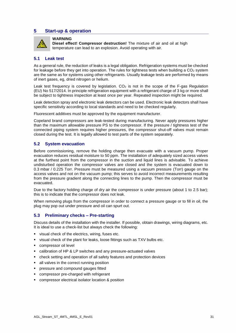
5 Start-up & operation
WARNING Diesel effect! Compressor destruction! The mixture of air and oil at high temperature can lead to an explosion. Avoid operating with air.
5.1 Leak test
As a general rule, the reduction of leaks is a legal obligation. Refrigeration systems must be checked for leakage before they get into operation. The rules for tightness tests when building a CO2 system are the same as for systems using other refrigerants. Usually leakage tests are performed by means of inert gases, eg, dried nitrogen or helium.
Leak test frequency is covered by legislation. CO2 is not in the scope of the F-gas Regulation (EU) No 517/2014. In principle refrigeration equipment with a refrigerant charge of 3 kg or more shall be subject to tightness inspection at least once per year. Repeated inspection might be required.
Leak detection spray and electronic leak detectors can be used. Electronic leak detectors shall have specific sensitivity according to local standards and need to be checked regularly.
Fluorescent additives must be approved by the equipment manufacturer.
Copeland brand compressors are leak-tested during manufacturing. Never apply pressures higher than the maximum allowable pressure PS to the compressor. If the pressure / tightness test of the connected piping system requires higher pressures, the compressor shut-off valves must remain closed during the test. It is legally allowed to test parts of the system separately.
5.2 System evacuation
Before commissioning, remove the holding charge then evacuate with a vacuum pump. Proper evacuation reduces residual moisture to 50 ppm. The installation of adequately sized access valves at the furthest point from the compressor in the suction and liquid lines is advisable. To achieve undisturbed operation the compressor valves are closed and the system is evacuated down to 0.3 mbar / 0.225 Torr. Pressure must be measured using a vacuum pressure (Torr) gauge on the access valves and not on the vacuum pump; this serves to avoid incorrect measurements resulting from the pressure gradient along the connecting lines to the pump. Then the compressor must be evacuated.
Due to the factory holding charge of dry air the compressor is under pressure (about 1 to 2.5 bar); this is to indicate that the compressor does not leak.
When removing plugs from the compressor in order to connect a pressure gauge or to fill in oil, the plug may pop out under pressure and oil can spurt out.
5.3 Preliminary checks – Pre-starting
Discuss details of the installation with the installer. If possible, obtain drawings, wiring diagrams, etc. It is ideal to use a check-list but always check the following:
▪ visual check of the electrics, wiring, fuses etc.
▪ visual check of the plant for leaks, loose fittings such as TXV bulbs etc.
▪ compressor oil level
▪ calibration of HP & LP switches and any pressure-actuated valves
▪ check setting and operation of all safety features and protection devices
▪ all valves in the correct running position
▪ pressure and compound gauges fitted
▪ compressor pre-charged with refrigerant
▪ compressor electrical isolator location & position
32 AGL_Stream_ST_4MTL_4MSL_E_Rev01
5.4 Charging procedure
CAUTION Low suction pressure operation! Compressor Damage! Do not operate with a restricted suction. Do not operate with the low-pressure cut-out bridged. Do not operate compressor without enough system charge to maintain at least 6 bar absolute suction pressure. Allowing the absolute pressure to drop below 6 bar for more than a few seconds might cause CO2 solidification which would block valves or pipes.
CAUTION Low moisture content! Corrosive impact on refrigeration system! Use only high-dried CO2 quality.
Charge the system with vapour CO2 up to a minimum absolute pressure of 6 bar to prevent dry ice
formation. A gaseous pre-charge of 10 bar in the whole system is common practice. Then continue
charging with liquid CO2. The system should be charged through the liquid-receiver shut-off valve or
through a valve in the liquid line. The use of a filter drier in the charging line is highly recommended.
As there may be several valves in the system it is recommended to charge on both the high and low
sides simultaneously to ensure a sufficient pressure is present in the compressor before it runs. The
majority of the charge should be placed in the high side of the system to prevent bearing washout
during first-time start.
5.5 Initial start-up
CAUTION Oil dilution! Bearing malfunction! It is important to ensure that new compressors are not subjected to liquid abuse. Turn the crankcase heater on 12 hours before starting the compressor.
CAUTION High discharge pressure operation! Compressor damage! Do not use compressor to test opening setpoint of high-pressure cut-out.
The compressor must be equipped according to our technical documentation considering the application intended. Make sure this requirement is met before start-up.
For brazing connections where dissimilar or ferric metals are joined a silver alloy rod with a minimum silver content of 34 % shall be used being either flux-coated or with a separate flux.
Bolt torque settings are listed in Appendix 2.
With the exception of rubber-coated metallic gaskets (Wolverine), all gaskets and O-rings should be oiled before fitting.
NOTE: A compressor should never be operated outside its approved application range!
Check the corresponding data sheet. To avoid motor damage, NEVER start the compressor
or carry out high-potential testing when the compressor is under vacuum.
5.6 Minimum run time
Emerson recommends a maximum of 10 starts per hour. The most critical consideration is the minimum run time required to return oil to the compressor after start-up.

AGL_Stream_ST_4MTL_4MSL_E_Rev01 33
5.7 Inverter operation
Stream compressors are released for inverter applications with inverters from Control Techniques or other brands available on the market.
Compressor Nominal power
Displacement m3/h @ 50 Hz
Approved frequency
ranges
Recommended mounting parts
Su
bcri
tiq
ue
4MSL-03 3 hp 4.6
25 - 70 Hz
Hard rubber kit # 3189744
4MSL-04 4 hp 6.2
4MSL-06 6 hp 7.4
4MSL-08 8 hp 9.5
25 - 70 Hz 4MSL-12 12 hp 12.5
4MSL-15 15 hp 17.9
Tra
nsc
riti
qu
e
4MTL-05 5 hp 4.6
30 - 70 Hz 4MTL-07 7 hp 6.2
4MTL-09 9 hp 7.4
4MTL-12 12 hp 9.5
25 - 70 Hz 4MTL-15 15 hp 12.5
4MTL-30 30 hp 17.9
4MTL-35 35 hp 22.7 30 - 70 Hz
(check approved application envelope)
4MTL-40 40 hp 26.6
4MTL-50 50 hp 32.0
Table 14: Inverter operation – Approved frequency ranges
NOTE: The frequency range depends on the operating conditions. For approved application envelope please contact Application Engineering or refer to Select Software at www.climate.emerson.com/en-gb.
5.7.1 Maximum Operating Current – Models 4MTL-35 to 4MTL-50
Large Stream CO2 compressors from 35 to 50 hp have a different MOC in operation with frequency drives. Table 15 below shows the values for both types of operation.
Compressor MOC (A) MOCVS (A)
4MTL-35 59.6 67.1
4MTL-40 67.4 75.8
4MTL-50 82.7 90.6
Table 15: Maximum operating current for large Stream CO2 compressor
5.7.2 Recommendations for use with an inverter
Running the Stream CO2 compressor with an inverter is a reliable application. Nevertheless resonances might occur in the lower frequency ranges. This phenomenon strongly depends on the system design and operating conditions.
Emerson conducted extensive tests to investigate compressor behaviour in terms of resonances. The testing indicates that the following hardware variables have a significant impact on possible resonances:
▪ Mounting parts: The rubber mounting parts supplied with Stream compressors are suitable for the whole frequency range from 25 to 70 Hz.
▪ Piping design: It is recommended to pay particular attention to the discharge line design. A discharge pipe parallel to the compressor axis normally gives a positive effect to reduce resonances at low frequencies.
▪ Base frame design: The framework structure should be stiff enough to ensure that its resonance frequencies are above the maximum 70 Hz frequency. A design with natural frequencies below the minimum 25 Hz speed may lead to high vibrations during start-up.

34 AGL_Stream_ST_4MTL_4MSL_E_Rev01
NOTE: Performance data and envelopes are published in Copeland brand products Select software at www.climate.emerson.com/en-gb.

AGL_Stream_ST_4MTL_4MSL_E_Rev01 35
6 Maintenance & repair
6.1 Exchanging the refrigerant
4MTL* and 4MSL* compressors are released for use with CO2 refrigerant only. The replacement of CO2 with any other refrigerant is not allowed.
In the event that the refrigerant needs replacing, the CO2 charge does not need to be recovered and can be blown off into the environment. Ensure that no oil is blown off (use a filter drier). It is essential to ensure a good ventilation or evacuation of the CO2 refrigerant to avoid a risk of suffocation.
6.2 Replacing a compressor
CAUTION Inadequate lubrication! Bearing destruction! Exchange the accumulator after replacing a compressor with a burned-out motor. The accumulator oil return orifice or screen may be plugged with debris or may become plugged. This will result in starvation of oil to the new compressor and a second failure.
In the case of a motor burnout, the majority of contaminated oil will be removed with the compressor.
The rest of the oil is cleaned through the use of suction and liquid line filter driers. A 100 % activated
alumina suction line filter drier is recommended but must be removed after 72 hours. It is highly
recommended that the suction accumulator be replaced if the system contains one. This is
because the accumulator oil-return orifice or screen may be plugged with debris or may become
plugged shortly after a compressor failure. This will result in starvation of oil to the replacement
compressor and a second failure. When a single compressor or tandem is exchanged in the field, it
is possible that a major portion of the oil may still be in the system. While this may not affect the
reliability of the replacement compressor, the extra oil will add to rotor drag and increase power
usage.
6.3 Lubrication and oil removal
CAUTION Chemical reaction! Compressor destruction! Do not mix up ester oils with mineral oil and/or alkyl benzene.
The compressor is supplied with an initial oil charge. The standard oil charge for use with R744 refrigerant is a polyolester (POE) lubricant Emkarate RL 68 HB.
One disadvantage of POE is that it is far more hygroscopic than mineral oil (see Figure 39). Only brief exposure to ambient air is needed for POE to absorb sufficient moisture to make it unacceptable for use in a refrigeration system. Since POE holds moisture more readily than mineral oil it is more difficult to remove it through the use of vacuum. Compressors supplied by Emerson contain oil with low moisture content, and it may rise during the system assembling process. Therefore it is recommended that a properly sized filter-drier is installed in all POE systems. This will maintain the moisture level in the oil to less than 50 ppm. If oil is charged into a system, it is recommended to use POE with moisture content no higher than 50 ppm.
Figure 39: Absorption of moisture in ester oil in comparison to mineral oil in ppm by weight at 25 °C and 50 % relative humidity (h=hours)
The diagram in Figure 39 compares the hygroscopic characteristics of POE oil with mineral oil (moisture absorption in ppm at 25 °C and 50 % relative humidity). If the moisture content of the oil in
36 AGL_Stream_ST_4MTL_4MSL_E_Rev01
a refrigeration system reaches unacceptably high levels, corrosion and copper plating may occur. The system should be evacuated down to an absolute pressure of 0.3 mbar or lower.
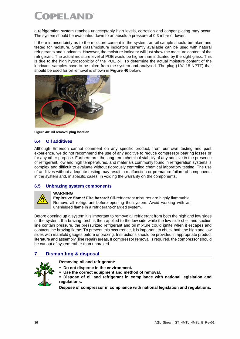
If there is uncertainty as to the moisture content in the system, an oil sample should be taken and tested for moisture. Sight glass/moisture indicators currently available can be used with natural refrigerants and lubricants. However, the moisture indicator will just show the moisture content of the refrigerant. The actual moisture level of POE would be higher than indicated by the sight glass. This is due to the high hygroscopicity of the POE oil. To determine the actual moisture content of the lubricant, samples have to be taken from the system and analysed. The plug (1/4"-18 NPTF) that should be used for oil removal is shown in Figure 40 below.
Figure 40: Oil removal plug location
6.4 Oil additives
Although Emerson cannot comment on any specific product, from our own testing and past experience, we do not recommend the use of any additive to reduce compressor bearing losses or for any other purpose. Furthermore, the long-term chemical stability of any additive in the presence of refrigerant, low and high temperatures, and materials commonly found in refrigeration systems is complex and difficult to evaluate without rigorously controlled chemical laboratory testing. The use of additives without adequate testing may result in malfunction or premature failure of components in the system and, in specific cases, in voiding the warranty on the components.
6.5 Unbrazing system components
WARNING Explosive flame! Fire hazard! Oil-refrigerant mixtures are highly flammable. Remove all refrigerant before opening the system. Avoid working with an unshielded flame in a refrigerant-charged system.
Before opening up a system it is important to remove all refrigerant from both the high and low sides of the system. If a brazing torch is then applied to the low side while the low side shell and suction line contain pressure, the pressurized refrigerant and oil mixture could ignite when it escapes and contacts the brazing flame. To prevent this occurrence, it is important to check both the high and low sides with manifold gauges before unbrazing. Instructions should be provided in appropriate product literature and assembly (line repair) areas. If compressor removal is required, the compressor should be cut out of system rather than unbrazed.
7 Dismantling & disposal
Removing oil and refrigerant:
▪ Do not disperse in the environment. ▪ Use the correct equipment and method of removal. ▪ Dispose of oil and refrigerant in compliance with national legislation and regulations.
Dispose of compressor in compliance with national legislation and regulations.

AGL_Stream_ST_4MTL_4MSL_E_Rev01 37
Appendix 1: Connections of Stream CO2 compressors
4MTL* 4MSL* 4MTL-05 4MTL-07 4MTL-09 4MSL-03 4MSL-04 4MSL-06 4MTL-12 4MTL-15 4MTL-30 4MSL-08 4MSL-12 4MSL-15 4MTL-35 4MTL-40 4MTL-50
Figure 41
SL Suction line size (sweat) 4MSL-03, 4MSL-04, 4MSL-06 4MTL-05, 4MTL-07, 4MTL-09
ID: 5/8" Tube OD: 16.15 mm
DL Discharge line size (sweat) 4MSL-03, 4MSL-04, 4MSL-06 4MTL-05, 4MTL-07, 4MTL-09
ID: 1/2" Tube OD: 12.85 mm
SL Suction line size (sweat) 4MSL-08, 4MSL-12, 4MSL-15 4MTL-12, 4MTL-15, 4MTL-30
ID: 7/8" Tube OD: 22.40 mm
DL Discharge line size (sweat) 4MSL-08, 4MSL-12, 4MSL-15 4MTL-12, 4MTL-15, 4MTL-30
ID: 5/8" Tube OD: 16.15 mm
SL Suction line size (sweat) 4MTL-35, 4MTL-40, 4MTL-50
ID: 1 3/8" Tube OD: 35.25 mm
DL Discharge line size (sweat) 4MTL-35, 4MTL-40, 4MTL-50
ID: 1 1/8" Tube OD: 28.75 mm
1 Base mountings Ø 22 mm 4 Crankcase heater No thread
2 Plug low-pressure connection 1/2"
14 NPTF 5 Plug high-pressure connection
1/8" 27 NPTF
3 Plug low-pressure connection / Oil drain plug
1/4" 18 NPTF
Table 16
5
38 AGL_Stream_ST_4MTL_4MSL_E_Rev01
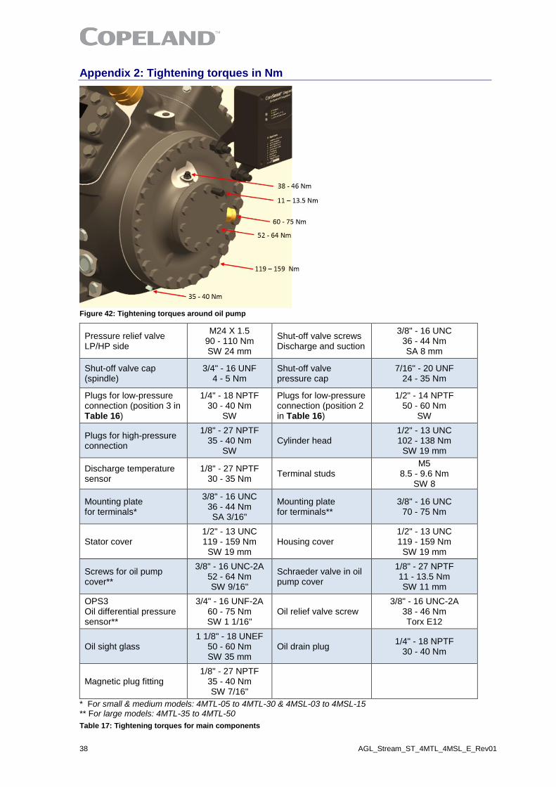
Appendix 2: Tightening torques in Nm
Figure 42: Tightening torques around oil pump
Pressure relief valve LP/HP side
M24 X 1.5 90 - 110 Nm SW 24 mm
Shut-off valve screws Discharge and suction
3/8" - 16 UNC 36 - 44 Nm SA 8 mm
Shut-off valve cap (spindle)
3/4" - 16 UNF 4 - 5 Nm
Shut-off valve pressure cap
7/16" - 20 UNF 24 - 35 Nm
Plugs for low-pressure connection (position 3 in Table 16)
1/4" - 18 NPTF 30 - 40 Nm
SW
Plugs for low-pressure connection (position 2 in Table 16)
1/2" - 14 NPTF 50 - 60 Nm
SW
Plugs for high-pressure connection
1/8" - 27 NPTF 35 - 40 Nm
SW Cylinder head
1/2" - 13 UNC 102 - 138 Nm
SW 19 mm
Discharge temperature sensor
1/8" - 27 NPTF 30 - 35 Nm
Terminal studs M5
8.5 - 9.6 Nm SW 8
Mounting plate for terminals*
3/8" - 16 UNC 36 - 44 Nm SA 3/16"
Mounting plate for terminals**
3/8" - 16 UNC 70 - 75 Nm
Stator cover 1/2" - 13 UNC 119 - 159 Nm
SW 19 mm Housing cover
1/2" - 13 UNC 119 - 159 Nm
SW 19 mm
Screws for oil pump cover**
3/8" - 16 UNC-2A 52 - 64 Nm SW 9/16"
Schraeder valve in oil pump cover
1/8" - 27 NPTF 11 - 13.5 Nm SW 11 mm
OPS3 Oil differential pressure sensor**
3/4" - 16 UNF-2A 60 - 75 Nm SW 1 1/16"
Oil relief valve screw 3/8" - 16 UNC-2A
38 - 46 Nm Torx E12
Oil sight glass 1 1/8" - 18 UNEF
50 - 60 Nm SW 35 mm
Oil drain plug 1/4" - 18 NPTF
30 - 40 Nm
Magnetic plug fitting 1/8" - 27 NPTF
35 - 40 Nm SW 7/16"
* For small & medium models: 4MTL-05 to 4MTL-30 & 4MSL-03 to 4MSL-15 ** For large models: 4MTL-35 to 4MTL-50
Table 17: Tightening torques for main components

AGL_Stream_ST_4MTL_4MSL_E_Rev01 39
Figure 43: Hexagon socket screws (Allen / Inbus) & hexagon heads (Wrench)
The ranges of torque values given in this specification are assembly torques. Torque after joint relaxation must be within 15 % of the minimum assembly torque unless re-torque is called for and must not be above 10 % of the maximum assembly torque.
40 AGL_Stream_ST_4MTL_4MSL_E_Rev01
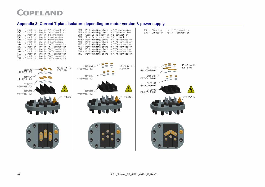
Appendix 3: Correct T-plate isolators depending on motor version & power supply

AGL_Stream_4MTL_4MSL_E_Rev01 41
Disclaimer
1. The contents of this publication are presented for informational purposes only and are not to be construed as warranties or guarantees, express or implied, regarding the products or services described herein or their use or applicability.
2. Emerson Climate Technologies GmbH and/or its affiliates (collectively "Emerson"), as applicable, reserve the right to modify the design or specifications of such products at any time without notice.
3. Emerson does not assume responsibility for the selection, use or maintenance of any product. Responsibility for proper selection, use and maintenance of any Emerson product remains solely with the purchaser or end user.
4. Emerson does not assume responsibility for possible typographic errors contained in this publication.

42 AGL_Stream_ST_4MTL_4MSL_E_Rev01

AGL_
Stre
am_S
T_4M
TL_4
MSL
_E_R
ev01
BENELUXJosephinastraat 19NL-6462 EL KerkradeTel: +31 45 535 06 73Fax: +31 45 535 06 [email protected]
UK & IRELANDUnit 17, Theale Lakes Business ParkReading, Berkshire RG7 4GB Tel: +44 1189 83 80 00Fax: +44 1189 83 80 [email protected]
BALKANSelska cesta 93HR-10 000 ZagrebTel: +385 1 560 38 75Fax: +385 1 560 38 [email protected]
GERMANY, AUSTRIA & SWITZERLANDTheo-Mack Str. 3DE-63477 MaintalTel: +49 6109 605 90Fax: +49 6109 60 59 [email protected]
SWEDEN, DENMARK, NORWAY & FINLANDPascalstr. 65DE-52076 AachenTel: +49 2408 929 0Fax: +49 2408 929 [email protected]
FRANCE, GREECE & MAGHREB8, Allée du Moulin BergerFR-69134 Ecully Cédex, Technoparc - CS 90220Tel: +33 4 78 66 85 70Fax: +33 4 78 66 85 [email protected]
EASTERN EUROPE & TURKEYPascalstr. 65DE-52076 AachenTel: +49 2408 929 0Fax: +49 2408 929 [email protected]
ROMANIA & BULGARIAParcul Industrial Tetarom 2 Emerson Nr. 4 400641 Cluj-NapocaTel: +40 374 13 23 50Fax: +40 374 13 28 [email protected]
ITALYVia Ramazzotti, 26IT-21047 Saronno (VA)Tel: +39 02 96 17 81Fax: +39 02 96 17 88 [email protected]
POLANDSzturmowa 2PL-02678 WarsawTel: +48 22 458 92 05Fax: +48 22 458 92 [email protected]
MIDDLE EAST & AFRICAPO Box 26382Jebel Ali Free Zone - South, Dubai - UAETel: +971 4 811 81 00Fax: +971 4 886 54 [email protected]
ASIA PACIFICSuite 2503-8, 25/F., Exchange Tower33 Wang Chiu Road, Kowloon BayKowloon , Hong KongTel: +852 2866 3108Fax: +852 2520 6227
CZECH REPUBLICHajkova 22 CZ - 133 00 Prague Tel: +420 733 161 651Fax: +420 271 035 [email protected]
SPAIN & PORTUGALC/ Pujades, 51-55 Box 53ES-08005 BarcelonaTel: +34 93 412 37 [email protected]
RUSSIA & CISDubininskaya 53, bld. 5RU-115054, MoscowTel: +7 - 495 - 995 95 59Fax: +7 - 495 - 424 88 [email protected]
For more details, see www.climate.emerson.com/en-gb
The Emerson logo is a trademark and service mark of Emerson Electric Co. Emerson Climate Technologies Inc. is a subsidiary of Emerson Electric Co.Copeland is a registered trademark and Copeland Scroll is a trademark of Emerson Climate Technologies Inc.. All other trademarks are property of their respective owners.Emerson Climate Technologies GmbH shall not be liable for errors in the stated capacities, dimensions, etc., as well as typographic errors. Products, specifications, designs and technical data contained in this document are subject to modification by us without prior notice. Illustrations are not binding.
© 2019 Emerson Climate Technologies, Inc.
Emerson Commercial & Residential SolutionsEmerson Climate Technologies GmbH - Pascalstrasse 65 - 52076 Aachen, GermanyTel. +49 (0) 2408 929 0 - Fax: +49 (0) 2408 929 570 - Internet: www.climate.emerson.com/en-gb
Connect with us: facebook.com/EmersonCommercialResidentialSolutions
Top Related