


Languages
Pages
Legal


REPORT NO.
UCB/EERC-87/19
NOVEMBER 1987
PB88-178983
EARTHQUAKE ENGINEERING RESEARCH CENTER
ANALYTICAL MODELS FOR PREDICTINGTHE LATERAL RESPONSE OFRCSHEAR WALLS:EVALUATION OF THEIR RELIABILITY
by
ALFONSO VULCANO
VITElMO V. BERTERO
Report to the National Science Foundation
REPRODUCED BY
U.S. DEPARTMENT OF COMMERCENATIONAL TECHNICALINFORMATION SERVICESPRINGFIELD, VA. 22161
COLLEGE OF ENGINEERING
UNIVERSITY OF CALIFORNIA AT BERKELEY

For sale by the National Technical Information Service, U.S. Department of Commerce,Springfield, Virginia 22161.
See back of report for up to date listing ofEERC reports.
DISCLAIMERAny opinions, findings, and conclusions orrecommendations expressed in this publication are those of the authors and do notnecessarily reflect the views of the NationalScience Foundation or the Earthquake Engineering Research Center, University ofCalifornia, Berkeley

Analytical Models for predicting the Lateral Response of R C
Shear Walls: Evaluation of their Reliability
!llI1U 1\11
REPORT DOCUMENTATION 11. REPORT NO.. 12. 3. Reclplent'a IIccaulon No. I1 r)_AG_1E -I..-_--'-N_SF_/_EN_G_-8_7_04_2 ...L- +r:.-B-=---:::.g....=.!-=-:...-.:../....:..7.....:a:.-9~a_::.3~.
4. Title and Subtitle 5. Report Date
November 1987
1--------'-------------------------_.. ---------------17. Author(s)
Alfonso Vulcano and Vitelmo V. Bertero9. Performlnll Organization Name and Address
Earthquake Engineering Research CenterUni vers ity of Cal iforni a1301 South 46th StreetRichmond, California 94804
12. Sponsorln&: Organization Nama and Address
National Science Foundation1800 G. Street, N.W.Washington, D.C. 20550
15. Supplementary Notes
16. Abstract (Limit: 200 words)
8. Performln&: Ol'll:anlzatlon Rept. No.
UCB/ EERC-87/1910. Project/Task/Work Unit No.
11. ContractCC) or GrantCG) No.
CC)
CG) CEE 80-0947813. Type of Report &. Pellod Covered
14.
mainadalwhich
load
Attention is focused on a wall model recently proposed by Japanese researchers. Thismodel, based on a macroscopic approach, idealizes the generic wall member as three verticalline elements with infinitely rigid beams at the top and bottom floor levels. The twooutside elements are truss elements to represent the axial stiffness of the boundarycolumns; the central element is a one-component model constituted by horizontal, verticaland rotational springs to represent, respectively, the shear stiffness of the wall, thevertical axial stiffness and the flexural stiffness of the central panel.
Modifications of this wall model are developed in the studies reported. Themodification is aimed at improving the simulation of the hysteretic behavior of theelements adopted by the Japanese. These axial elements are replaced by new elementssimulate more closely the hysteretic behavior of aRC column member under axialreversals.
In order to check the effectiveness and reliability of the modified wall model anumerical investigation is carried out by calibrating the results against measured behaviorof a series of R C structural walls that have been tested at the University of California atBerkeley. The modified wall model proves to be effective and suitable for incorporation in apractical nonlinear analysis of R C multistory structural systems.
17. Document Analysis a. Descriptors
b. Identifiers/Open·Ended Terms
c. CaSATI Field/Group
18. Availability Statemen:
Release unlimited
19. Security CI••s (ThIs Report)
Unclassified20. Security Clasa (This Palle)
Uncl assi fied22. Price
nk),1)
'II
See Inatructlona on R.v.ra.,J c
OPTIONAL FORM 212 (4-77)'Fe,r.",,,,:,I\CIS--3S)
r Commerce


ANALYTICAL MODELS FOR PREDICTING
THE LATERAL RESPONSE OF R C SHEAR WALLS:
EVALUATION OF THEIR RELIABILITY
by
Alfonso VulcanoAssociate Professor
Dipartimento di Strutture - Universita della CalabriaArcavacata di Rende (Cosenza) - Italy
and
Vitelmo V. BerteroProfessor of Civil Engineering
University of California - Berkeley
A Report to Sponsor:
National Science Foundation
Report No. UCB/EERC - 87119
Earthquake Engineering Research Center
College of Engineering
University of California
Berkeley, California
November 1987


ABSTRACT
Relative simplicity with reasonable reliability is emphasized as the prerequisite of
aRC shear wall model to be incorporated in a practical nonlinear analysis of a RC
multistory structural system containing shear walls. Attention is focused on a wall
model recently proposed by Japanese researchers. This model, based on a macroscopic
approach, idealizes the generic wall member as three vertical line elements with
infinitely rigid beams at the top and bottom floor levels. The two outside elements are
truss elements to represent the axial stiffness of the boundary columns; the central
element. is a one-component model constituted by horizontal, vertical and rotational
springs to represent, respectively, the shear stiffness of the wall, the vertical axial
stiffness and the flexural stiffness of the central panel.
Modifications of the above wall model are proposed and developed in the studies
reported herein. The main modification is aimed to improve the simulation of the
hysteretic behavior of the axial elements adopted by the Japanese researchers. These
axial elements are replaced by new elements which simulate more closely the hysteretic
behavior of aRC column member under axial load reversals.
In order to check the effectiveness and reliability of the modified wall model a
numerical investigation is carried out by calibrating the results against measured
behaviour of a series of R C structural walls that have been tested at the University of
California at Berkeley.
The modified wall model proves to be effective and suitable to be incorporated in
a practical nonlinear analysis of R C multistory structural systems. Even though an
apparently satisfactory correlation of the measured and analytical responses is found,
under high shear stresses the correct prediction of the flexural and shear displacement
components of the total displacement is very difficult and very sensitive to the choice of
many of the parameters involved in the modified wall model.
Some recommendations are advanced in order to improve further the analytical
wall model.
- i - (.

ACKNOWLEDGEMENTS
The research reported herein was supported, in part, by the National Science
Foundation Grant Number CEE 80-09478. The research started as a part of a
cooperative research program between Italy and the U.S.A., sponsored by the
Italian Research Council.
This part of the research was completed during the stay of Professor Alfonso
Vulcano at the University of California at Berkeley as a Visiting Scholar. Profes
sor Vulcano gratefully acknowledges the financial support of the Training and
Studies Center of Southern Italy.
Finally, the authors wish to acknowledge the assistance of Dr. Beverley Bolt
for the editing of this report.
Preceding page blank - iii -


TABLE OF CONTENTS
CHAPTER I-INTRODUCTION
1.1 General
1.2 Objectives and Scope of the Report
CHAPTER 2 - GENERAL REVIEW OF R C WALL MODELS
2.1 Introduction
2.2 Models Derived from a Macroscopic Approach
2.2.1 Equivalent Beam Model
2.2.2 Equivalent Truss Model
2.2.3 Three-Vertical-Line-Element Model
CHAPTER 3 - SELECTED WALL MODEL:THREE-VERTICAL-LINE-ELEMENT MODEL
3.1 General Description of the Model
3.2 Hysteresis Model
3.2.1 Axial-Stiffness Hysteresis Model
3.2.2 Origin-Oriented Hysteresis Model
1
1
2
4
4
6
6
7
8
9
9
10
10
12
Preceding page blank -v-

3.3 Stiffness Properties of the Model Elements
3.3.1 Truss Elements
3.3.2 Central Element Springs
(a) Vertical Spring
(b) Horizontal Spring
(c) Rotational Spring
3.4 Proposed Axial-Stiffness Hysteresis Model
CHAPTER 4 - METHOD OF ANALYSIS
4.1 Wall Discretization and Elastic Stiffness Matrix
4.2 Equilibrium Equations andIterative Solution Process
CHAPTER 5 - NUMERICAL STUDIES
5.1 General
5.2 Description of the Test Structures
5.3 Modeling of the Test Structures
5.4 Comparison of Experimental and Analytical Curves
5.4.1 Monotonic Loading (Specimens 3 and 5)
5.4.2 Cyclic Loading (Specimens 4 and 6)
5.5 Parametric Studies
- vi -
13
13
13
13
13
15
17
20
20
21
23
23
23
24
25
25
26
28

CHAPTER 6 - SUMMARY, CONCLUSIONSAND RECOMMENDATIONS
6.1 Summary
6.2 Conclusions
6.3 Recommendations for Future Research
REFERENCES
APPENDIX A
APPENDIXB
TABLES
FIGURES
- vii-
34
34
36
37
39
45
49
53
57


CHAPTERl
INTRODUCTION
1.1 General
The use of Reinforced Concrete (R C) shear walls in multistory buildings is very
effective in providing resistance and stiffness against lateral loads induced by wind
and/or earthquake. Well-designed R C coupled walls and frame-wall structural systems
are particularly effective during severe earthquake ground motions when a considerable
amount of the energy input has to be dissipated by reversed inelastic deformations.
Extensive research, both analytical and experimental [1-39], has been carried out
in order to clarify, and then to simulate, the hysteretic behavior of isolated and coupled
R C walls, as well as of R C frame-wall structural systems. Recent research has
improved the understanding of the inelastic behavior of such structures significantly.
These advances have provided helpful information for the development of suitable
analytical models.
An analytical model should be capable of closely describing both the hysteretic
behavior of each structural member and the interaction of connected members.
Nevertheless, the analytical model should be relatively simple so that the analysis can
be performed with reasonable computational effort. This last requirement is particularly
important when multistory structural systems have to be analyzed. In these cases,
models derived from a macroscopic approach prove to be more effective than detailed
mechanical models. In fact, the former models require relatively limited storage and,
most important, significantly lower computational effort.
- 1 -

Although suitable analytical models have been proposed for realistic and practical
prediction of the hysteretic behavior of R C beam members, many uncertainties about
the formulation of a reliable model for the practical analysis of R C structural walls
persist. Therefore, while there has been a marked improvement in the analysis of R C
frame structures in the last two decades, the analysis of R C frame-wall structural
systems has not comparably improved.
Many important features of the hysteretic behavior observed during experiments
on a full-scale seven-story building have been incorporated in the Three-Verti
cal-Line-Element Model, recently proposed by Kabeyasawa et aI. [27] to simulate the
inelastic response of R C structural walls. Even though there is good correlation
between the observed and computed responses for the overall structure, further
improvements in the wall model are believed possible.
In this report attention is focused on the modeling of R C structural walls and, in
particular. on the aforementioned model which is shown to be reasonably reliable and
suitable for incorporation in a practical nonlinear analysis of multistory structural
systems.
1.2 Objectives and Scope of the Report
The main objectives of the work described in this report are as follows:
(1) to discuss features and limitations of previously proposed R C shear wall models
and to select a relatively simple and reasonably reliable wall model, that can be
efficiently incorporated in a practical nonlinear analysis of R C multistory structural
systems that use R C shear walls;
(2) to check the effectiveness and reliability of the selected wall model in light of the
measured behavior of isolated R C structural walls;
- 2 -

(3) to evaluate the sensitivity of the response of the selected wall model to the
characteristic parameters involved in the analysis;
(4) to make suggestions that would improve the reliability of the selected wall model.
In Chapter 2 a general review of R C wall models available in the literature is
given, discussing their features and limitations.
In Chapter 3 attention is focused on the Three-Vertical-Line-Element Model. An
analytical model idealizing the hysteretic behavior of aRC column member under axial
load reversals is proposed and incorporated in the aforesaid wall model.
In Chapter 4 the features of the nonlinear analysis adopted and the computer
program coded on the basis of this method are discussed.
Results of a numerical investigation and a parametric study, referring to a group of
isolated R C structural walls tested by Vallenas et al. [4] at the University of California
at Berkeley, are presented and discussed in Chapter 5.
Lastly, in Chapter 6 the conclusions of the present work and recommendations for
future research are given.
- 3 -

CHAPTER 2
GENERAL REVIEW OF R C WALL MODELS
2.1 Introduction
Many analytical models have been proposed to predict the nonlinear response of
R C structural walls. However, they can be classified into two broad groups:
(1) detailed models derived using mechanics of solids (microscopic approach);
(2) simplified models to predict a specific overall behavior (macroscopic approach).
Models derived from a microscopic approach are based on a detailed interpreta
tion of the local behavior. Even though the microscopic approach is desirable, its
implementation involves many difficulties due both to the lack of completely reliable
basic models and the complexities involved in a detailed solution. Although, the Finite
Element Method offers a powerful analytical tool to perform the numerical analysis
[40], the computation is generally very time-consuming and requires a large storage:
thus, in practice the microscopic approach is restricted to the analysis of structural
systems less complex than multistory frame-wall structural systems, such as a single
wall or an assemblage of two coupled walls.
On the other hand, models based on a macroscopic approach attempt to describe
the overall behavior by means of a simplified idealization. The main advantages of
these models consist in the relatively limited storage and, above all, in the significantly
less computational effort than that required by detailed analytical models. However,
-4-

models deriving from a macroscopic approach have several limitations, the main one
being that usually the analytical results are valid only for the conditions on which the
derivation of the model is based.
An alternative to the two above-mentioned approaches would be their combina
tion. For instance, simplified models could be used to idealize structural members
whose inelastic deformations are expected to be predominant; or, a preliminary analysis
by a microscopic approach could provide helpful information about the structural
idealization to be adopted in selecting a suitable simplified model.
In any case the model which is adopted, regardless of the approach from which it
has been derived, should describe and predict the different components of inelastic
deformation: flexural and shear deformations, as well as fixed end rotation caused by
bond slippage of the tensile reinforcement embedded in the foundation. Moreover, the
model should be capable of simulating the observed deformation patterns due to
different failure modes: flexural, sliding shear or splitting-crushing of the web at the
base of the wall.
It should be noted that to have an efficient wall system the web splitting-crushing
mode of failure should be avoided or delayed sufficiently so that it will not control the
behavior of the system. Although this mode of failure can be simulated when a
microscopic approach is followed, its simulation becomes very difficult by models
based on a macroscopic approach. In spite of this limitation, in the following emphasis
will be placed on simplified models derived from a macroscopic approach, because they
are relatively simple and, therefore, suitable for efficient incorporation in a nonlinear
analysis of multistory structural systems in which splitting-crushing of the web is
avoided or delayed enough not to be the controlling mode of failure.
- 5 -

2.2 Models Derived from a Macroscopic Approach
2.2.1 Equivalent Beam Model (EBM)
One current modeling technique for a frame-wall system considers the generic
shear wall member replaced at its centroidal axis by a line element and connected by
rigid links to the frame beams; the fixed-end rotation at any connection interface with
the frame beams can be taken into account by introducing a nonlinear rotational spring
whose mechanical properties can be defined on the basis of bar slippage due to bond
deterioration.
Computer programs based on a one-component model are generally used [41-42].
This model consists of a flexural elastic member with a nonlinear rotational spring at
each end. The inelastic moment-rotation relationship of each spring is determined by
assuming a given location of the contraflexure point, e.g. that one based on the initial
elastic stage. This is an advantage, because the inelastic end rotation depends only on
the bending moment at the end and any moment-rotation hysteresis model can be
adopted for the spring. However, this feature of the model is also a weakness, because
the actual moment distribution and the propagation of inelasticity along the beam are
disregarded.
In order to account for the variation of location of the contraflexure point, Otani
[43] introduced some modifications to the model. But when the contraflexure point
moves suddenly a numerical problem arises because of the sign change of the member
end moments. To overcome this difficulty and to simulate the propagation of
inelasticity adequately, the wall element can be discretized into a suitable number of
short segments [36-39]; or different models [44-45], more sophisticated than a
one-component model, can be adopted in order to account for the spread of the inelastic
deformations in the critical regions . These models, however, and in particular the
- 6-

further subdivision when a one-component model is adopted require such large storage
and computational effort as to make the analysis of multistory structural systems
unfeasible.
To account for the inelastic shear deformation effects in a coupled wall system,
Takayanagi et al. [37] introduced additional plastic hinges at the ends of each line
element representing a wall member. Although the computed and measured responses
matched very well, it is important to observe that the sliding deformation mode of the
wall cannot be represented.
The main limitation of modeling R C structural walls by adopting any equivalent
beam model lies in the assumption that rotations occur around points belonging to the
centroidal axis of the wall. With this assumption important features of the behavior of
R C frame-wall structural systems (Le., migration of the neutral axis of the wall
cross-section, rocking of the wall, etc.) are disregarded and their consequent effects
(i.e., outriggering interaction with the frame surrounding the wall, etc.) are not
accounted for adequately.
2.2.2 Equivalent Truss Model (ETM)
Another modeling technique represents the wall as an equivalent truss system.
Unlike the beam model, this model accounts for the stress redistribution caused by the
diagonal cracks. However, difficulties arise in defining both the geometry and the
mechanical properties of the equivalent truss system. For example, on the basis of
experimental test results, Hiraishi [29] introduced a non-prismatic truss member whose
cross-sectional area was determined taking into account the stress along the height of
the boundary column under tension.
Further difficulties are due to changes in the structural topology which depends on
crack propagation during the loading history. Helpful information in regards to this can
be provided by a preliminary finite element solution, but the analysis is then much more
time-consuming [4].
- 7 -

2.2.3 Three-Vertical-Line-Element Model (TVLEM)
Recently, after experiments on a full-scale model of a seven-story Rebuilding,
Kabeyasawa et al. developed a mathematical model for R C structural walls [27]. A
good correlation of the observed and computed responses was found. The wall model,
although relatively simple, incorporates the main features of the experimentally
observed behavior (i.e., migration of the neutral axis of the wall cross-section, rocking
of the wall, etc.), which the equivalent beam model fails to describe, as mentioned in
Section 2.2.1.
For this reason the TVLEM can be considered to be one of the most suitable
models among the R C wall models available in the literature for incorporation in a
practical nonlinear analysis of multistory structural systems. In the next Chapters
attention will be focused on this type of model and some proposals made for improving
the original model.
It is worth mentioning that the TVLEM can be generalized as a Multi-Verti
cal-Line-Element Model. An approach of this kind was followed by Charney [22], who
adopted a multi-axial-spring-in-parallel model (LINKS Model) to describe the flexural
inelastic behavior of the base of a structural R C wall, part of a lI5-scale test frame-wall
structure.
- 8 -

CHAPTER 3
SELECTED WALL MODEL:
THREE-VERTICAL-LINE-ELEMENT MODEL
3.1 General Description of the Model
The model shown in Fig. 3.1a was fonnulated by Kabeyasawa et al. [27] to
idealize a generic wall member as three vertical line elements with infinitely rigid
beams at the top and bottom floor levels: two outside truss elements represented the
axial stiffness of the boundary columns, while the central element was a one-component
model with vertical, horizontal and rotational springs concentrated at the base.
However, a finite rigid element of length ch could be placed between the spring
assembly and the lower rigid beam. * The wall model was intended to simulate the
defonnation of the wall member under a unifonn distribution of curvature.
* The value of the dimensionless parameter c could be chosen in such a way that ch
represents the height of the center of relative rotation between top and bottom levels
(Fig. 3.1b). With a suitable choice of the c value it is possible to define an effective
relationship between the relative flexural displacement L1vflexural and the relative rotation
L1<j> ( L\V flexural :::: (c-1) h L\<j> ). A suitable value of c can be selected as based on the
expected curvature distribution along the inter-story height h (0 $. c < 1, if the curvature
sign does not change along the inter-story height).
- 9 -

The model is capable of describing flexural and shear deformations, while the
deformation due to the fixed end rotation is not accounted for. Flexural and sliding
shear modes of failure can be described, while, as already mentioned in Section 2.1 for
all the models based on a macroscopic approach, the web splitting-crushing mode of
failure is not simulated.
The hysteresis models and stiffness properties (illustrated in Sections 3.2 and 3.3,
respectively) adopted by Kabeyasawa et al. to simulate the hysteretic behavior of the
model elements were based on the experience coming from experimental tests. Many of
the assumptions contained in Sections 3.2 and 3.3 are empirical and sometimes even
seem arbitrary. Nonetheless many of these assumptions, unless differently specified, are
kept in the studies reported herein in order to check the reliability of the model. A
parametric study is presented in Chapter 5 to emphasize the sensitivity of the wall
model to different values of the characteristic parameters affecting the model response.
3.2 Hysteresis Models
3.2.1 Axial-Stiffness Hysteresis Model (ASHM)
The behavior of aRC column under axial load reversals is very complex. The
simplified model shown in Fig. 3.2 was proposed in Reference 27 and tentatively used
to describe the axial force-deformation relationship of the three vertical line elements of
Fig.3.1a.
The skeleton curve was defined by assuming the axial stiffness as constant in
compression. When the net axial load changed its sign from compression to tension, the
stiffness was reduced to 90% of the initial compressive elastic stiffness in order to
account for some stiffness degradation due to cracking and bond deterioration. After
- 10-

tensile yielding - supposed to occur when longitudinal reinforcement yielded under the
net tensile load - the stiffness was reduced to 0.1 % of the initial elastic stiffness in order
to represent some strain hardening.
Before reaching the point Y = (Dyt' Fy) corresponding to tensile yielding, the
response point followed the usual bilinear hysteresis rules between the two points Y and
Y' = (D ,-F).yc y
Once tensile yielding occurred, then the response point followed the bilinear
hysteresis rules between Y' and the point M = (Dm, Fm) corresponding to the maximum
tensile strength Fm previously attained. The unloading stiffness K, was assumed to be
(3.1)
in which
Dyt = tensile yielding point deformation;
Dm
= maximum deformation amplitude greater than Dyt;
a = unloading stiffness degradation parameter, which was assumed equal to 0.9. *
* It should be noted that the choice of the a value is very important in order to obtain arealistic unloading path. In fact, the greater is the tensile ductility factor ~t = DjDyt thesmaller is the unloading stiffness K" which, according to Eq. (3.1), could ahain the limitvalue ~im =Klim(~' a) indicated in Fig. 3.3a. In other words, for each value of~, a limitvalue ~im can be defined for the parameter a such that, if a > ~im ( a < ~im) thenK, < K 1im (K, > KIirrJ' However, the unloading path defined by the condition K, < K 1im, thatis K, < K,', is unrealistic because during an unloading phase subsequent to a tensileyielding the response of the R C column strongly depends on the steel behavior, whichdoes not match a path of this type.
It can be shown that~im =log {[2KJ K c + (~,-l)KJ K)] / [KJ K c + ~t]} / log ~;l , ~, > I
Some curves representing ~im versus ~, for different values of the ratio K, / Kc areplotted in Fig. 3.3b. All these curves, which prove to be practically insensitive to thevalue of the ratio ~ / Kc' refer to the value 0.001 assumed for this ratio in Reference 27.It is worth noting that, by referring to the curve corresponding to the values assumed inReference 27 for a , K, / K c and ~ / K c (0.90, 0.90 and 0.001, respectively), theunloading stiffness K, attains the limit value for ~,== 1.165 ; in order to have K, > K 1imfor any realistic choice of the~, value, then a < 0.687.
- 11 -

Furthennore, additional rules were applied between Y' and M. During a loading
phase in tension, when the response point reached the point M, then the response point
moved on the branch of the skeleton curve in tension corresponding to the tensile
hardening stiffness Kh, in this way renewing the point M. Moreover, during an
unloading phase from M the response point reached the point (Dx ' Fm - Fy) and then
moved toward the compressive characteristic point Y'; however, the point Y' was not
reached because the response point moved toward the point Y" == (2DyC' -2F) from
the stiffness hardening point P == (Dp' Fp) corresponding to the defonnation
D == D + A (D - D ) (3.2)p yeP x yc
in which
Dx == deformation at the point corresponding to the change of the unloading stiffness;
~ == parameter for stiffness hardening point, which was assumed equal to 0.2.
3.2.2 Origin-Oriented Hysteresis Model (OOHM)
An Origin-Oriented Hysteresis Model, which dissipates small hysteresis energy,
was used for both the rotational and horizontal springs at the base of the central vertical
element (Fig. 3.4). A trilinear skeleton curve was used for both these springs. The
response point moved along a line connecting the origin and the previous maximum
response point in each direction. Once the response point reached the previous
maximum point, the response point followed the skeleton curve renewing the maximum
response point.
It should be noted that, because of the choice of the OORM, the shear stiffness
degradation was taken without accounting for the cracking effects due to the presence
of both the actual axial force and the bending moment. As pointed out later in the
discussion of the numerical investigation (Chapter 5), there are discrepancies between
the measured and predicted shear behaviors for the test walls considered in this work,
whereas in Reference 27 the predicted response of the overall structure correlated very
- 12-
well with the observed one. These different results arise because in the latter case the
inelastic behavior of the tested structure was essentially flexural, while the shear
stiffness remained practically elastic.
Although in the studies reported herein attention is focused on the ASRM, the
above-mentioned discrepancies require that the use of the OORM to represent the
stiffness properties of the horizontal spring be revised.
3.3 Stiffness Properties of the Model Elements
3.3.1 Truss Elements
The axial stiffness properties of the two outside truss elements (represented by the
stiffnesses K j and K2 in Fig. 3.1a) were defined as for an independent column by
referring to the area of the boundary columns. As previously said, the hysteretic
behavior was simulated by using the ASHM.
3.3.2 Central Element Springs
(a) Vertical Spring
The axial stiffness properties of the central element (represented by the stiffness
Kv in Fig. 3.1a) were determined by referring to the area of the central panel bounded
by the inner faces of the two boundary columns. The same rules adopted for the truss
elements were used to describe the hysteretic behavior of the vertical spring belonging
to the central element.
(b) Horizontal Spring
The shear resistance of the wall was provided by the horizontal spring in the
central element.
- 13-

The value of the stiffness of the horizontal spring (KH in Fig. 3.la) in the initial
elastic range represents the shear stiffness of the wall in this range, which was defined
as
(3.3a)
in which
G == elastic shear modulus;
Aw
== area of the shear wall section (Fig. 3.5);
X == shape factor for shear deformation;
h == inter-story height.
The shape factor X was calculated by the following formula proposed by Tomii and
Osaki [24]:
X== 3(l+u)[I-u2(l-v)] I 4[I-u3(1-v)]
in which u and v are the geometrical parameters shown in Fig. 3.5.
The shear cracking was assumed to occur at a shear force
(3.3b)
(3.4)
The ultimate shear resisting capacity was calculated by the empirical formula
proposed by Hirosawa [25]:
Vu = [0.0679 PIO.23 (fo'+17.6) I (M I V L + 0.12)112 + 0.845 (fwh Pwh)t12 + O.lao] bej
(f.' and fWh in MPa) (3.5)
where
PI == effective tensile reinforcement ratio as a percentage =100 As I be (L - a/2);
As == area of longitudinal reinforcement in tension-side boundary column;
M I V L =shear-span-to-depth ratio;
Pwh =effective horizontal wall reinforcement ratio =Aws I be s;
be == average width of wall section;
s = spacing of horizontal wall reinforcement;
- 14-

Go = average stress over entire wall cross-section area;
j = (7/8)(L - al2);
L, a =geometrical parameters (Fig. 3.5).
In Reference 27 the ratio as of the stiffness after shear cracking to the initial elastic
stiffness K s was determined by the empirical formula:
(3.6)
The stiffness after shear yielding was taken to be 0.1 % of the initial elastic
stiffness K s in order to account for some strain hardening.
(c) Rotational Spring
The stiffness properties of the rotational spring (represented by the stiffness K~ in
Fig. 3.1a) were defined by referring to the wall area bounded by the inner faces of the
two boundary columns. Even though it is not completely clear how these properties
were defined, it seems that the displacement compatibility of the central panel with the
boundary columns was disregarded.
For the purpose of computing the wall rotation, the bending moment was assumed
to distribute uniformly along the story height with an amplitude equal to the moment at
the critical section of the wall.
Cracking would occur when the extreme fiber strain under the gravity load and
overturning moment became zero in its way to be a tensile strain. The yielding moment
was calculated as the moment about the centroid of the wall section caused by the
yielding of all vertical reinforcement, including also the gravity loading effect. The
stiffness after yielding was taken to be 0.1 % of the initial elastic stiffness, assuming in
this way some strain hardening.
It should be noted that the assumption of these stiffness properties regardless of
the displacement compatibility results in a wrong evaluation of the flexural and axial
contributions of the central panel to the response of the entire wall. This is emphasized
in Figs. 3.6a and 3.6b, in which, respectively, the flexural moment around the central
- 15 -

axis and the axial force, both versus curvature, are shown for the entire wall and its
parts (boundary columns and central panel). All the curves refer to the section of a
framed wall tested by Vallenas et al. [4] (Specimen 3), which was subjected to a
constant axial force NT =868 kN.
The analytical curves were obtained using the computer program UNCOLA [46].
In Fig. 3.6a the curve obtained for the central panel assumed isolated is shown together
with the curve corresponding to the entire wall as well as the curves obtained for the
boundary columns and the same central panel by satisfying the condition of displaceme
nt compatibility. These last two curves were obtained on the basis of the same strain
profile associated with each of the values of the curvature that were considered by
analyzing the entire wall cross-section. The same procedure was used to calculate the
contributions of axial force which correspond to the boundary columns (No) and central
panel (Np) according to the condition of displacement compatibility (Fig. 3.6b).
As shown in Fig. 3.6a, the flexural contribution of the central panel results in a
more marked softening effect when the condition of displacement compatibility is
satisfied. Under this last condition a decompression effect is observed for the central
panel, whereas it is subjected to a constant compression force if supposed isolated, that
is if the displacement compatibility with the boundary columns is disregarded (Fig.
3.6b).
In view of these results, the assumptions made by Kabeyasawa et al. about the
stiffness properties of the rotational spring seem questionable. In fact, in Reference 27
the OOHM described in Section 3.2.2 was adopted also for the rotational spring, thus
accounting for some strain hardening, and the axial force in the central panel was
assumed constant.
In order to overcome the above-mentioned limitations, in the following all the
properties of the rotational spring, unless differently specified, will be defined by a
moment-curvature analysis based ort the displacement compatibility. The moment-cur
vature relationship (M-'I') so derived is idealized as a trilinear curve. As a consequence,
- 16-

the skeleton curve of the rotational spring is also idealized as trilinear and the
moment-rotation (M-<\» relationship under cyclic loading is simulated by the OOHM
already presented in Section 3.2.2. As an example, in Fig. 3.7 the idealization of the
moment-curvature relationship is shown with reference to the central panel of Specimen
3, whose flexural response based on the condition of displacement compatibility has
been previously shown in Fig. 3.6a (see also APPENDIX A).
3.4 Proposed Axial-Stiffness Hysteresis Model
The behavior of aRC column under axial load reversals is not clearly understood.
Kabeyasawa et al. developed and tentatively used the ASHM described in Section 3.2.1,
the properties of which were defined by empirical laws and some assumptions based on
results from experimental tests.
In order to have a better understanding of the hysteretic behavior of the column
and reduce the empirical assumptions, the model shown in Fig. 3.8a is proposed and
incorporated in the selected wall model. The column member is idealized as two axial
elements in series: one element (i.e., element 1) is a one-component model to represent
as a whole the axial stiffness of the column segments in which the bond is still active,
while the other element (i.e., element 2) is a two-component model to represent the
axial stiffness of the remaining segments of steel and cracked concrete (i.e., components
(S) and (C), respectively) for which the bond has almost completely deteriorated.
The proposed model is capable of idealizing the main features of the actual
hysteretic behavior of the materials and their interaction: yielding, hardening and the
Bauschinger effect for the steel, cracking of the concrete and onset of contact stresses
during the closure of cracks, degradation of the bond between concrete and steel and so
on. Adequate constitutive laws should be used to idealize the actual behavior of the
steel and concrete, particularly the variation of the contact stress during the closure of
cracks. Moreover, a suitable law should be used for the dimensionless bond-degradation
- 17 -

parameter A, which also defines the lengths of the two elements constituting the model
in order to simulate the tension-stiffening effect. Even though refined results can
generally be attained by very sophisticated assumptions, above all it is desirable to
simplify the mathematical model to limit the cost of the numerical analysis.
To carry out a first check of the accuracy that can be achieved by the proposed
ASHM, very simple assumptions are made here which preserve, however, the essential
features of the above-mentioned observed phenomena. In particular, the constitutive
laws for the model components shown in Fig. 3.8a are simply taken to be as follows:
linearly elastic for the overall element 1; bilinear with the hardening slope depending on
the value r assumed for the steel-hardening ratio, and linearly elastic in compression
neglecting the tensile strength capacity of the concrete, respectively, for the components
Sand C constituting the element 2.
According to the simplified assumptions just mentioned, the axial force-deforma
tion relationship for the column member is of the kind shown in Fig. 3.8b, in which
typical states of the model (Le., steel yielding in tension and compression, as well as
closure of the cracks) can be easily recognized on the basis of the idealized constitutive
laws. The stiffnesses in compression Ko' in tension Kt and after tensile yielding Kh can
be expressed by the following equations, respectively:
Kc = (Ec Ac + E. A.) / h
Kt = I/{ (l-A)h / (Eo Ac + E. A.) + Ah / (E. A.)}
Kh = 1 / {(l-A)h / (Eo Ao+ E. As) + Ah / (r EsAs)}
(3.7a)
(3.7b)
(3.7c)
in which r is the steel hardening ratio and the same value Ec
has been assumed for the
concrete modulus in compression and in tension.
From Eqs. (3.7), once the value of the model stiffness in compression Kois fixed,
the values of both the stiffness in tension Kt and the stiffness after tensile yielding ~
can be adjusted by assuming for A and r suitable values to simulate the observed
- 18 -
hysteretic behavior. In the following, even though this is questionable, the values of K,
and ~ will be selected according to the corresponding values adopted by Kabeyasawa
et al. (K, = 0.90 Kc ; ~ =0.001 K) in order to check the reliability of the wall model.
However, in order to check the sensitivity of the response of the wall model to different
choices of these parameters a parametric study was conducted and the results are
presented in Chapter 5.
It is important to note that, even though the primary skeleton curve is the same for
both axial-stiffness hysteresis models shown in Figs. 3.2 and 3.8b, the hysteretic
behavior under cyclic loading is generally different. The ASHM in Fig. 3.2 contains
more rules than the simplified hysteresis model in Fig. 3.8b. Notwithstanding, the
model proposed here, besides being easily recognizable, is capable of many improve
ments (Le., more-refined constitutive laws for the model components based on the
observed hysteretic behavior of the materials, suitable laws to idealize the contact
effects due to the closure of cracks, calibration of the bond-degradation parameter 'A
according to experimentally observed tension-stiffening effects on the basis of a
suitable law for describing the degradation of the steel-concrete bond, etc.).
- 19 -
CHAPTER 4
METHOD OF ANALYSIS
4.1 Wall Discretization and Elastic Stiffness Matrix
The wall is discretized as a set of wall members, one for each story. The generic
wall member is idealized by the wall model described in Chapter 3, modified by the
inclusion of the proposed ASHM.
The elastic stiffness matrix K. [6x6] of the generic wall member is formulated
with reference to the six displacementlload components at the center of the top and
bottom rigid beams (Fig. 3.1a). By assuming in general a finite rigid element of length
ch placed between the spring assembly of the central element and the lower rigid beam
(Fig. 3.1b), the matrix K. is defined by the following equation in terms of elastic
energy:
1/2 u.T K. u. =1/2 {(Kl+Kz+Kv) (wm- w.....y + [K~+(Kl+~)QH4] (<pm- <1>.....)2+
+ 9, (Kz-K1) (wm- Wm) (<pm- <Pm) + KH[vm- V.....1+ (l-c)h<l>m+ ch<l>m_Y} (4.1)
where u. = {vm'wm,<I>m'v.....l'wm.l'<P.....l}T is the displacement vector of the generic wall
member (Fig. 3.1a). The matrix K. so formulated is shown in Fig. 4.1.
The elastic stiffness matrix KE [3n x 3n] of the wall is hence obtained as an
assemblage of the stiffness contributions of the n wall members in which the wall has
been discretized.
- 20-

4.2 Equilibrium Equations and Iterative Solution Process
The analytical response of the wall is evaluated by an incremental step-by-step
procedure. At each step of the analysis, once the initial conditions and the increment of
the load vector p [3n xl] are known, the state of strain and stress at the step end is
obtained by the initial stress-like iterative procedure shown in Fig. 4.2.
On the basis of a trial displacement vector uI(k) [3n x 1] for the discretized wall at
the end of the step, the stress state in the generic spring constituting the wall element
can be calculated. This can be accomplished in an explicit way for the horizontal and
rotational springs, while an iterative procedure is generally needed for the truss
elements and central vertical spring, for which the hysteretic behavior is described by
the proposed two-element-in series model described in Section 3.4.
This iterative procedure is needed in order to satisfy the following incremental
equations, which express displacement compatibility and equilibrium, respectively:
~D = ~DI + ~D2
~FI (~DI) = ~F2 (~DJ = ~F
(4.2a)
(4.2b)
where the subscripts 1 and 2 refer, respectively, to the two elements in series
constituting the axial model. However, the iterative procedure, which is described in
detail in Fig. 4.3, is not necessary before cracking occurs (/\.=0) or if the stiffening
effect is negligible ("-=1).
Finally, once the stress state of each spring is known, the vector s[uI(k)] [3n xl],
which represents the structural reaction corresponding to the trial displacement vector at
the end of the step, can be calculated. In order to find the displacement vector u l such
that the corresponding vector s[u l ] satisfies the equilibrium equations, the following
iterative scheme is used:
- 21 -

U Ck+l) =U (Ie) - H r Ck)1 1
(4.3a)
(4.3b)
where the index k refers to the generic iteration loop and H is a suitable iteration matrix.
The iterative process is stopped when an appropriate measure of the residual vector r Ck)
becomes less than a prefixed tolerance.
As shown in Reference 47, the convergence of the iterative process (4.3) is
ensured under very broad hypotheses on the mechanical behavior of the structure if the
iteration matrix is taken as
(4.3)
where KM is a maximizing stiffness matrix (e.g., the elastic stiffness matrix KE if the
behavior is elastic-perfectly plastic) and ~ a generic tangent stiffness matrix of the
discretized structure.
The procedure just described has been coded as a computer program for the
nonlinear analysis of R C structural walls. The flow chart of this computer program,
which is organized by subroutines (INPUT, LOADS, ASSEM, SOLVE , STRUCT,
OUTPUT) to perfonn different operations, is shown in Fig. 4.4.
- 22-

CHAPTER 5
NUMERICAL STUDIES
5.1 General
In order to check the effectiveness and the reliability of the R C wall model
obtained by incorporating in the wall model presented in Reference 27 the ASHM
proposed in this report (Section 3.4), a numerical investigation was carried out using the
computer program presented in Section 4.2. Parametric studies were also performed to
evaluate the sensitivity of the response of such a wall model to the characteristic
parameters involved in the analysis. For these purposes isolated R C structural walls
previously tested at the Earthquake Engineering Research Center of the University of
California at Berkeley provided the experimental results and are referred to as the test
structures.
After a description of these test structures and their modeling, the analytical
results obtained for the wall model will be compared with the experimental ones.
Lastly, the results of the parametric study will be presented.
5.2 Description of the Test Structures
The four 1/3-scale test specimens, previously tested at the University of California
at Berkeley by Vallenas et al. [4], were intended to idealize the three lower stories of
both a framed wall (Specimens 3 and 4, Fig. 5.1a) and rectangular wall (Specimens 5
- 23-

and 6, Fig. 5.1b) designed, respectively, for the ten-story and seven-story prototype
buildings shown in Figs. 5.2a and 5.2b, respectively. These buildings were designed in
such a way that earthquake ground motions could induce high shear stresses of the same
magnitude in both kinds of wall.
Detailed wall cross-sections and loading patterns of the specimens are shown in
Figs. 5.3 and 5.4, respectively. As it can be observed in Fig. 5.4, the axial force and
moment-to-shear ratio (M/V) were assumed constant for each of the specimens.
Specimens 3 and 5 were subjected to a monotonic loading, while Specimens 4 and 6
were subjected to a cyclic loading.
5.3 Modeling of the Test Structures
The test walls were modeled by idealizing each wall story as the wall member
model in Fig. 3.1a. The structural models so obtained are shown in Fig. 5.5a for
Specimens 3 and 4, and in Fig. 5.5b for Specimens 5 and 6. The stiffness properties of
the model elements were based on the mechanical properties of the materials reported
for the test walls at the time of testing in Reference 4 and are summarized in Table 5.1
and Table 5.2, respectively, for Specimen 3 (4) and Specimen 5 (6). Typical constitutive
curves of the steel and concrete (unconfined and confined) are shown in Fig. 5.6a and
Fig. 5.6b, respectively. Details of the stiffness properties of the model elements are
shown in APPENDIX A for Specimen 3 (4) and in APPENDIX B for Specimen 5 (6).
- 24-

5.4 Comparison of Experimental and Analytical Curves
5.4.1 Monotonic Loading (Specimens 3 and 5)
Experimental and computed responses are shown in Figs. 5.7 and 5.8, respective
ly, for the framed wall (Specimen 3) and rectangular wall (Specimen 5) subjected to
monotonic loading.
With reference to Figs. 5.7a and 5.8a, it should be noted that the analytical model
does not account for the fixed end deformation caused by slippage of the longitudinal
reinforcement along its embedment in the foundation. Even though this kind of
deformation (33 fIXed end ) contributed only a minor portion to the total displacement 33 at
the third floor (as reported in Reference 4), it has been subtracted from the total
displacement (33' = 33 - 33 f",ed end = 33 flexural + 33 slx:ar ) to make the experimental and
analytic~l curves shown in Figs 5.7a and 5.8a comparable.
The correlation of experimental and analytical curves is apparently good for plots
of base shear V versus the net top displacement 33 ' (Figs. 5.7a and 5.8a) as well as
versus the flexural displacement 33 flexural (Figs. 5.7b and 5.8b) or the shear displacement
33 ,lx:ar (Figs. 5.7c and 5.8c) at the third floor. However, it must be noted that, because of
the flattening of these curves near the maximum strength, it is very difficult to correlate
the flexural and shear displacement components of the analytical model and the
corresponding measured ones. A parametric study, the results of which are presented in
Section 5.5, pointed out that the values of these displacement components given by the
analytical model proved to be very sensitive to the choice of several parameters (e.g.,
bond degradation parameter A, steel hardening ratio r, yield shear Vy assumed for the
horizontal spring, etc.). Therefore, caution is recommended in assuming the computed
displacement components as a correct prediction of the measured displacement
components, particularly when high shear stresses are expected, as was the case for the
test walls considered in these studies.
- 25-

5.4.2 Cyclic Loading (Specimens 4 and 6)
In Fig. 5.9 analytical and experimental results for both the flexural and shear
displacement components of the framed wall under cyclic loading (Specimen 4) are
separately shown. The analytical results have been obtained as follows: for any value of
the measured net top displacement (0/ = 03 flexural + 03 shear) drawn in the characteristic
cycles of the loading program adopted for Specimen 4 (i.e., LP 0, 46,48, 58, 60, 70, 72,
82, 84), it is assumed that the analytical model will give the same value of this
displacement and therefore the base shear required to produce this value is computed.
Analogous results for the rectangular wall under cyclic loading (Specimen 6 ; LP
0, 149, 180,255,280,372,392,532,560) are shown in Fig. 5.10.
While for Specimen 4 (Fig. 5.9) the analytical model underestimates the shear
deformations (and overestimates the flexural ones) in comparison with the measured
ones, a better prediction of the two displacement components is observed in Fig. 5.10
for Specimen 6. However, as already said, such prediction depends on the choice of
several parameters. For instance, for Specimen 4, a good prediction of both the shear
and flexural displacement components is obtained by simply assuming for ~ a suitable
value greater than the adopted value (0.001 K).
In particular, the results shown in Fig. 5.10, besides showing the inadequacy of the
OOHM to idealize the measured hysteretic shear behavior accurately, show a satisfacto
ry correlation for the measured and analytical responses due to flexural deformations. It
should be noted that the flexural response idealized by the wall model essentially
depends on the assumptions adopted for the proposed ASHM.
In order to have an idea of the kind of response obtained by adopting the proposed
ASHM, the responses of the two outside truss elements and the central vertical spring,
all corresponding to the first story of the model of Specimen 6 in Fig. 5.5b, are shown in
Fig. 5.11. It is interesting to observe that, with reference to the generic cycle of loading
in Fig. 5.10 (for example, the loading cycle 1-2-1), while the response of both the
outside truss elements describes one loading cycle (for example, the loading cycle 1-2-1
- 26-

in Figs. S.11a, b), the response point of the central vertical spring moves twice in each
of the directions of loading (as, for example, in the loading process 1, 1',2, 2', 1 in Fig.
S.llc). Furthermore, the initial deformation of the central vertical spring, corresponding
to a shortening, is no longer attained during the loading cycles following the tensile
yielding of the same spring. Indeed, the minimum displacement progressively attained
during these loading cycles corresponds to a growing elongation of the centroidal axis
of the wall.
In spite of the simplified assumptions adopted in these studies for the proposed
ASHM (which, as mentioned in Section 3.4, is certainly capable of improvement), the
flexural response idealized by the wall model compares satisfactorily with that obtained
by the use of more sophisticated models.
To emphasize this last assertion, in Fig. 5.12 the flexural response obtained for
Specimen 4 by adopting the wall model considered in these studies is compared with
the two curves reported in Reference 4, which were obtained experimentally and by
using the ASNR-I computer program, both with reference to a loading cycle corre
sponding to the range ±20 mm of the flexural displacement at the third leveL
Even though the simplified wall model considered in these studies provides a
description of the measured flexural response slightly less accurate than that obtained
by the detailed finite element solution (ANSR-I) reported in Reference 4, the
advantages arising from the use of the former model are obvious, particularly in terms
of computational effort. However, it should be noted that neither of the analytical
models accounts for the resistance degradation that Specimen 4 suffered because of
previous loading cycles.
- 27-

5.5 Parametric Studies
As mentioned in the previous section, for a given value of the net top displaceme
nt as well as of the flexural or shear displacement component, there is a good
correlation betweeen the experimental and analytical values of the shear strength. On
the other hand, for a given value of shear strength close to the maximum shear strength
of the wall, the prediction by the wall model of the measured flexural and shear
displacement components has been very difficult, because of the flattening of the
experimental and analytical curves (Figs. 5.7 and 5.8).
In order to check the sensitivity of these two analytical displacement components
to different parameters involved in the analysis, a parametric study was carried out with
reference to Specimen 3.
Measured and analytical displacement components are compared in Figs. 5.13a
and 5.13b, which refer, respectively, to the third and first floor levels. The analytical
displacement components have been obtained by assuming different values of the
parameters c and Vy • It can be observed that the analytical displacement components
corresponding to the same data on which the results discussed in Section 5.4 are based
(in particular, c =0 and Vy = 1101 kN for all the stories) provide, in comparison with
the measured displacement components, an overestimation of the flexural displacement
and an underestimation of the shear displacement.
As shown in Fig. 5.13b, a good correlation of experimental and analytical curves
referring to the first level is obtained by simply assuming for c and V suitable values
(c == 0.20 and Vy = 1101 kN for all the stories). However, for these same values of c and
V the correlation of the curves corresponding to the third floor level is not satisfactoryy
(Fig.5.13a).
As shown in Fig. 5.13a, a satisfactory correlation of the displacement components
at the third floor level is obtained by assuming c =0.20 and different values of Vy
for
each story, depending on the corresponding value of the ratio M / V L (see APPENDIX
A). However, for these new values of Vy
the analytical wall model overestimates the net
- 28-

displacement (0[' =o[ sbear + O[ flcxursl ) and, particularly, the shear displacement component
at the first floor level (Fig. 5.13b). This last effect is produced by a concentration of
post-yielding shear deformations at the first story, because of the fact that the external
shear is constant along the story height (Fig. 5.4a), while the minimum value of the
yielding shear is just that corresponding to the first story (Vy= 1101 leN). On the other
hand, if the Vy value is assumed the same for all the stories, as in the two cases
previously discussed, the shear deformations are uniformly distributed among the three
stories.
, The results in Fig. 5.13 discussed above give some idea of the difficulty of
predicting by the adopted wall model the shear and flexural displacement components at
each floor for a given value of the shear, when this value is close to the maximum shear
strength. At the same time they show the need for carrying out an extensive parametric
study in order to check the sensitivity of the displacement components to different
parameters.
As can be observed in Fig. 5.14, the displacement components at the first floor are
very sensitive to the choice of the parameter c. Subsequent to the yielding of the truss
element in tension, depending on the choice of c, the occurrence of yielding in the
central vertical spring (when c =0 and c =0.20) and in the horizontal spring (when
c = 0.30 and c = 0.50) gives rise to a sudden increase of the flexural or shear
displacement component, respectively. For example, for c =0 the flexural displacement
is overestimated and the shear displacement underestimated, while the opposite hap
pens for c = 0.5. This last value of c, because of the trapezoidal curvature distribution
along the height of the first story of Specimen 3, can be considered an upper bound for
c.
As previously shown in Fig. 3.7, if the condition of disp~acement compatibility
between boundary columns and central panel is satisfied, the flexural response of the
central panel results in a softening effect for large deformations, while in Reference 27
a hardening effect is simulated by the OORM after yielding of the rotational spring. On
- 29-

the basis of a trilinear idealization of the skeleton curve of the rotational spring, the
sensitivity of the displacement components to different choices of the softening ratio p~
were studied. As shown in Fig. 5.15, the softening deformations of the rotational spring
can considerably affect the displacement components, in spite of the fact that the
flexural contribution of the central panel is relatively small in comparison with that
provided by the boundary columns (Fig. 3.6a): the larger the absolute value of p~ , the
larger the flexural deformations (the smaller the shear deformations). It should be noted
that, when a negative value of p~ is selected, a problem arises with the convergence of
the iterative procedure described in Section 4.2 if the corresponding tangent stiffness
matrix is not positive definite (see Reference 47). In order to avoid this problem, the
(positive) value of r selected for the axial-stiffness elements of the wall model should be
large enough to compensate the effect of the negative value of p~. For this reason all the
analytical results shown in Fig. 5.15 have been obtained by assuming the value r =
0.001, greater than the values specified in APPENDIX A for the outside truss elements
and the central vertical spring.
The sensitivity to the bond-degradation parameter Aand the steel hardening ratio r,
which affect the stiffness of the two outside truss elements and the central vertical
spring was also studied.
The results obtained by assuming different values of A for the two outside truss
elements are shown in Figs. 5.16 and 5.17, which correspond, respectively, to the values
p~ = a and p~ = - 0.03 of the softening ratio. All the curves have been obtained by
assuming the value r =0.001 for the steel hardening ratio.
A comparison of the curves in Figs. 5.16 and 5.17 shows that, while for p$ =a the
sensitivity to the Avalue selected for the two outside truss elements is less evident, for
p~ =- 0.03 the displacement components are very sensitive even to small variations of A.
Analogous results, which are omitted for the sake of brevity, have been obtained by
assuming different values of Aonly for the central vertical spring.
- 30-

As shown in Fig. 5.18 for the case of p~ =-0.03, the displacement components are
very sensitive to the choice of the r value selected for the outside truss elements and the
central vertical spring. It is interesting to note that, the greater the r value, the smaller
the flexural displacement at both the third floor (Fig. 5.18a) and first floor (Fig. 5.18b),
but the greater the net displacement at the first floor (0/ =01 shear + 01 flexural' Fig. 5.18b).
This last effect is due to the fact that the results shown in Fig. 5.18 have been
obtained by assuming different values of V y at each story (see APPENDIX A). As said
above with reference to Figs. 5.13, the assumption of the minimum value of Vy for the
first story of the wall model causes a concentration of post-yielding deformations at this
story. Thus, for greater values of r, while the first-floor flexural deformation decreases,
the first-floor shear deformation increases because of the greater value of the shear
which has to be developed in order to obtain by the wall model the same value of the
net top displacement at the third floor 03' attained for smaller values of r. The same
effect is observed in Figs. 5.15b, 5.16b and 5.17b, which show results based on the
same assumption about the Vy value.
All the above results show the difficulty of controlling the flexural and shear
displacement components by the wall model. Further difficulties arise in selecting
suitable values of the parameters in order to obtain an accurate description of the
flexural and shear response. Because of the inadequacy of the OORM to simulate the
shear behavior under high shear stresses, as pointed out in Section 5.4, attention is
focused on the flexural response.
The results shown in Fig. 5.19b refer to the flexural response of a wall member of
unit height under a uniform distribution of flexural moment. The results obtained from
the UNCOLA analysis, previously shown in Fig. 3.6a, by referring to the response of
the boundary columns and central panel under displacement compatibility, are com
pared with those obtained for the truss elements and rotational spring of the modified
wall model, whose stiffness properties were based on the data reported in APPENDIX
A, except r = 0.001. In order to compare the results corresponding to the UNCOLA
- 31 -
analysis with those obtained by the modified wall model for c = 0, the wall model
results have been plotted assuming an abscissa scale which is twice the abscissa scale
corresponding to the UNCOLA results. In this manner the results of the UNCOLA
analysis and those obtained by the modified wall model give the same horizontal
displacement for the wall member under consideration (Fig. 5.19a).
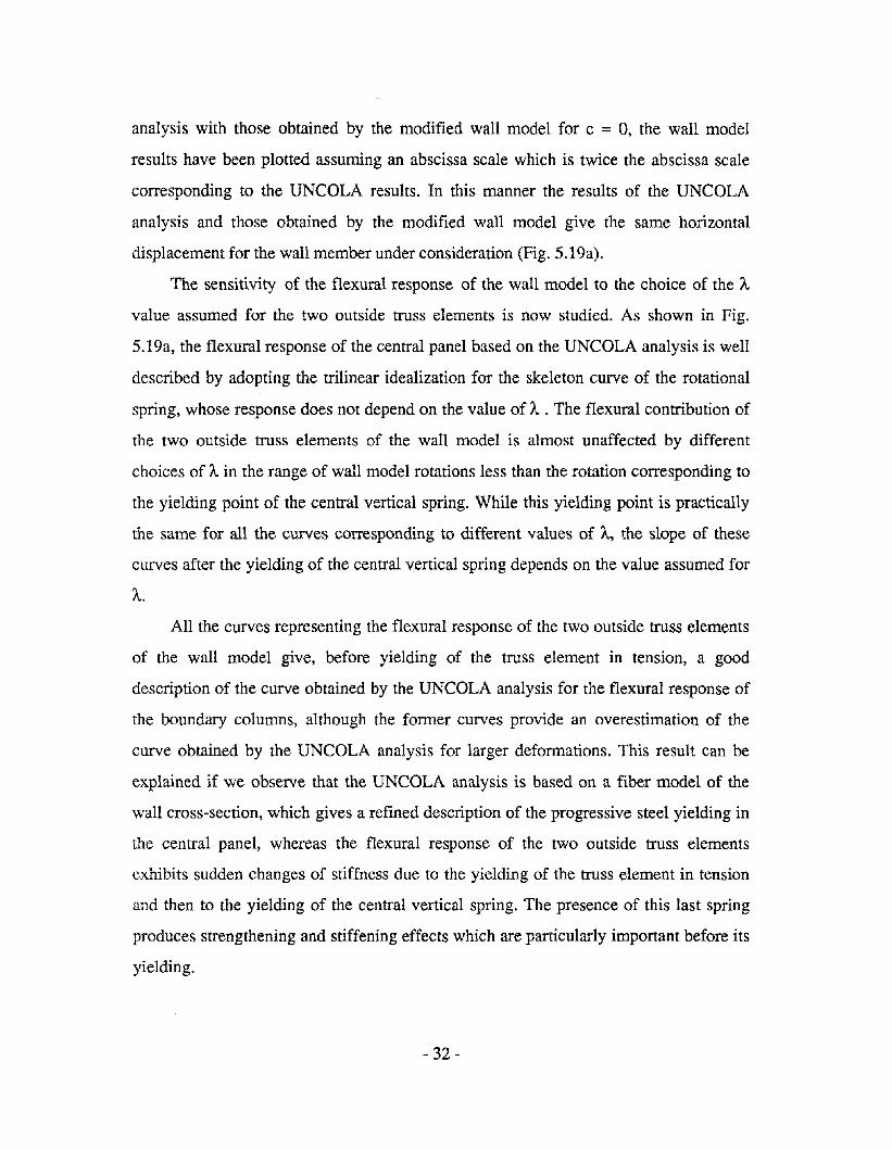
The sensitivity of the flexural response of the wall model to the choice of the A
value assumed for the two outside truss elements is now studied. As shown in Fig.
5.19a, the flexural response of the central panel based on the UNCOLA analysis is well
described by adopting the trilinear idealization for the skeleton curve of the rotational
spring, whose response does not depend on the value of A. The flexural contribution of
the two outside truss elements of the wall model is almost unaffected by different
choices of A in the range of wall model rotations less than the rotation corresponding to
the yielding point of the central vertical spring. While this yielding point is practically
the same for all the curves corresponding to different values of A, the slope of these
curves after the yielding of the central vertical spring depends on the value assumed for
A.All the curves representing the flexural response of the two outside truss elements
of the wall model give, before yielding of the truss element in tension, a good
description of the curve obtained by the UNCOLA analysis for the flexural response of
the boundary columns, although the former curves provide an overestimation of the
curve obtained by the UNCOLA analysis for larger deformations. This result can be
explained if we observe that the UNCOLA analysis is based on a fiber model of the
wall cross-section, which gives a refined description of the progressive steel yielding in
the central panel, whereas the flexural response of the two outside truss elements
exhibits sudden changes of stiffness due to the yielding of the truss element in tension
and then to the yielding of the central vertical spring. The presence of this last spring
produces strengthening and stiffening effects which are particularly important before its
yielding.
- 32-

In order to reduce these strengthening and stiffening effects and obtain a better
correlation between the results obtained by the UNCOLA analysis and the wall model,
the yielding strength of the central vertical spring was adjusted in a fictitious way (it
was reduced to the value F = 475 kN, against the actual value F = 803.088 kNy y
calculated in APPENDIX A). Nonetheless, this fictitious choice of Fy
for the central
vertical spring results in a better correlation of the results obtained by the UNCOLA
analysis (based on displacement compatibility) and the adopted wall model also in
terms of axial forces in the boundary columns and the central panel (Fig. 5.19c).
The results shown in Fig. 5.19 suggest that, in order to improve the description of
the flexural response by the wall model, it is desirable to modify this model in order to
have a more gradual description of the progressive steel yielding in the central panel.
For instance, the LINK Model proposed in Reference 22 pursues this objective, at least
with reference to the base of the wall.
- 33 -

CHAPTER 6
SUMMARY, CONCLUSIONS, AND RECOMMENDATIONS
6.1 Summary
The primary objective of the studies reported herein was to select among different
models available in literature a relatively simple and reasonably accurate wall model,
suitable for incorporation in a practical nonlinear analysis of R C multistory structural
systems that use shear walls.
For this purpose models based on a macroscopic approach are more suitable than
models based on a microscopic approach, which require a larger storage and are very
time-consuming. In Chapter 2, after discussing features and limitations of the models
available in the literature, attention is focused on the Three-Vertical-Line-Element
Model recently proposed by Kabeyasawa et al. [27]. This model was selected because,
although relatively simple, it incorporates the main features of the experimentally
observed behavior of R C structural walls (Le., migration of the neutral axis of the wall
cross-section, rocking of the wall, etc.). The model describes flexural and shear
deformations of the wall, while the deformation produced by the fixed end rotation due
to the slippage of the longitudinal reinfofcement embedded in the foundation is not
accounted fOf. The model can simulate flexural as well as sliding shear modes of
failure, but cannot simulate web crushing-splitting mode of failure, as is the case for all
the models based on a macroscopic approach.
- 34-

Chapter 3 gives details about the original wall model proposed by Kabeyasawa et
al. as well as about how the hysteresis models and stiffness properties of the elements
constituting this model were modified in the studies reported herein.
The axial hysteretic behavior of the elements constituting the modified wall model
is described by a two-element-in-series model, which is proposed in this report to
idealize the hysteretic behavior of aRC column member under axial load reversals.
The proposed Axial-Stiffness-Hysteresis Model takes advantage of the fact that its
mechanical properties are conceptually based on the actual hysteretic behavior of the
materials and their interaction, in such a way that the actual tension-stiffening effect can
be described. In defining the mechanical properties of the two elements in series
constituting this proposed model some simplifying assumptions are made.
Regarding the rotational and horizontal springs, which respectively describe the
flexural behavior of the central panel and the shear behavior of the wall, the
force-deformation relationship is based on an Origin-Oriented Hysteresis Model which
is the same as adopted in Reference 27.
In order to check the effectiveness and the reliability of the wall model so derived
a numerical investigation was carried out by assuming as test walls a group of R C
structural walls previously tested by VaIlenas et aI. [4]. For this purpose a computer
program, based on the numerical procedure described in Chapter 4, was developed.
In Chapter 5, after the description of the test walls and their modeling, the results
of the numerical investigation are presented and discussed.
Under monotonic loading the modified wall model predicts the measured shear
satisfactorily if the analytical and experimental results are compared for the same value
of the flexural or the shear displacement. If the same kind of comparison is made under
cyclic loading, the measured flexural response is still predicted with satisfactory
accuracy by the modified wall model. On the contrary, the measured shear response is
- 35-
not adequately described by the modified wall model under cyclic loading because of
the inadequacy of the Origin-Oriented Hysteresis Model to simulate the shear hys
teretic behavior under high shear stresses.
Furthermore, as a parametric study showed, under high shear stresses the
description of the measured flexural and shear displacement components by the
modified wall model is very difficult and very sensitive to the choice of many
parameters.
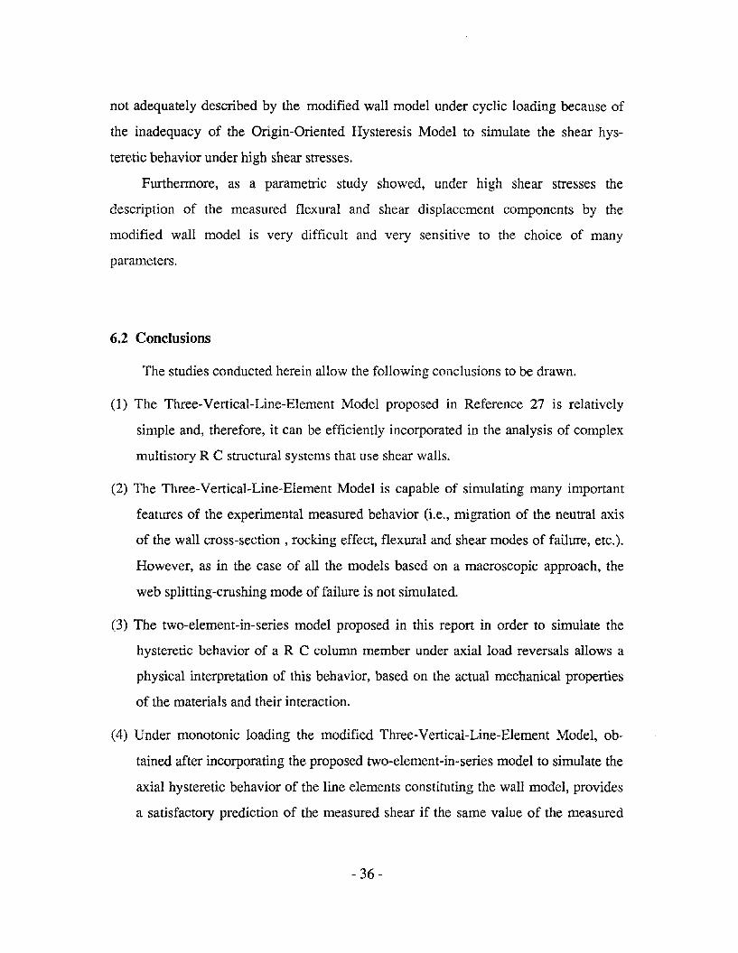
6.2 Conclusions
The studies conducted herein allow the following conclusions to be drawn.
(1) The Three-Vertical-Line-Element Model proposed in Reference 27 is relatively
simple and, therefore, it can be efficiently incorporated in the analysis of complex
multistory R C structural systems that use shear walls.
(2) The Three-Vertical-Line-Element Model is capable of simulating many important
features of the experimental measured behavior (i.e., migration of the neutral axis
of the wall cross-section, rocking effect, flexural and shear modes of failure, etc.).
However, as in the case of all the models based on a macroscopic approach, the
web splitting-crushing mode of failure is not simulated.
(3) The two-element-in-series model proposed in this report in order to simulate the
hysteretic behavior of aRC column member under axial load reversals allows a
physical interpretation of this behavior, based on the actual mechanical properties
of the materials and their interaction.
(4) Under monotonic loading the modified Three-Vertical-Line-Element Model, ob
tained after incorporating the proposed two-element-in-series model to simulate the
axial hysteretic behavior of the line elements constituting the wall model, provides
a satisfactory prediction of the measured shear if the same value of the measured
- 36-

flexural or shear defonnation is assumed for this wall modeL On the other hand, for
a given value of shear force near the maximum shear strength, it becomes very
difficult to predict the measured displacement accurately, because of the flattening
of the curves representing the relationship between the shear and the flexural
defonnation as well as between the shear and the shear defonnation.
(5) Under cyclic loading the modified Three-Vertical-Line -Element Model provides a
satisfactory simulation of the flexural hysteretic behavior if the same value of the
flexural displacement is assumed to compare analytical and experimental results.
The measured shear response, however, is not adequately described by the
modified wall model, because of the inadequacy of the Origin-Oriented-Hysteresis
Model to describe the shear hysteretic behavior for high shear stresses, as was the
case for the test walls considered in these studies.
6.3 Recommendations for Future Research
Even though the Three-Vertical-Line-Element Model proved to be effective and
reasonably accurate in simulating the hysteretic flexural behavior of the wall, further
improvements could be introduced by pursuing the following studies.
(1) A more refined description of the flexural behavior of the wall could be obtained
from one or both the following approaches:
(a) More refined (yet relatively simple) laws, based on the actual behavior of the
materials and their interaction, should be used to describe the response of the two
elements in series constituting the proposed Axial-Stiffness Hysteresis ModeL
(b) The geometry of the wall model should be modified on the basis of a
multi-axial-spring-in-parallel model (like the LINKS model adopted in Reference
22) in order to gradually account for the progressive yielding of the steel in the
central paneL
- 37 -

(2) Hysteresis models, more refined than the Origin-Oriented Hysteresis Model, should
be used to simulate the shear behavior of the wall when high shear stresses are
expected.
(3) Particularly under high shear stresses, the flexural and shear displacement compo
nents of the wall should be evaluated by relating in some way the flexural and shear
responses of the wall model, which at present are independently described by the
wall model - apart from satisfying the equilibrium condition. The wall model
should also be capable of accounting for variation of shear stiffness due to changes
of the axial and/or flexural strengths.
(4) Deformations produced by the fixed end rotation due to slippage of the longitudinal
reinforcement embedded in the foundation should be incorporated in the wall
model.
(5) Further efforts should be devoted to developing models based in part on a
microscopic approach, which would be capable of simulating the web splitting-cru
shing mode of failure, but would, at the same time, be relatively simple in order to
carry out the analysis in reasonable computational time. This could be achieved by
using more detailed models for those regions of the wall for which the above mode
of failure is expected (Le., the regions at the base of R C structural walls, which are
part of multistory frame-wall structural systems).
(6) A better calibration of the parameters affecting the response of the wall model is
needed in order to improve the prediction of the measured hysteretic behavior.
- 38 -

REFERENCES
[1] Park, R, and Paulay, T., Reinforced Concrete Structures, John Wiley and Sons,Inc., 1975.
[2] Paulay, T., "Earthquake Resistant Structural Walls", Proceedings of a Workshop onEarthquake Resistant Reinforced Concrete Building Construction [ERCBC],Bertero, V. V., organizer, Vol. Ill, pp. 1339-1365, University of California,Berkeley, 1977.
[3] Wang, T. Y., Bertero, V. V., and Popov, E. P. "Hysteretic Behavior of ReinforcedConcrete Framed Walls", Report No. UCB/EERC-75/23, Earthquake EngineeringResearch Center, University of California, Berkeley, 1975.
[4] Vallenas, J. M., Bertero, V. V., and Popov, E. P., "Hysteretic Behavior ofReinforced Concrete Structural Walls", Report No. UCB/EERC-79/20, Earthquake Engineering Research Center, University of California, Berkeley, 1979.
[5] lliya, R., and Bertero, V. V., "Effects of Amount of Arrangement of Wall-PanelReinforcement on Hysteretic Behavior of Reinforced Concrete Walls", Report No.UCB/EERC-80/04, Earthquake Engineering Research Center, University ofCalifornia, Berkeley, 1980.
[6] Bertero, V. V., "Seismic Behavior of R C Wall Structural Systems", Proceedings,7th World Conference on Earthquake Engineering, Vol. 6, Istanbul, Turkey, 1980.
[7] Harris, H. G., Bertero, V. V., and Clough, R. W., "One-Fifth Scale Model of aSeven-Story Reinforced Concrete Frame-Wall Building Under Earthquake Loading", Proceedings, International Seminar on Dynamic Modelling of Structures,Building Research Station, Garston, England, 1981.
[8] Aktan, A. E., and Bertero, V. V., "The Seismic Resistant Design of R C CoupledStructural Walls", Report No. UCB/EERC-81/07, Earthquake Engineering Research Center, University of California, Berkeley, 1981.
[9] Aktan, A. E., and Bertero, V. V., "Analytical and Physical Modeling of R CFrame-Wall/Coupled Wall Structures", Proceedings, International Seminar onDynamic Modelling of Structures, Building Research Station, Garston, England,1981.
[10] Aktan, A. E., and Bertero, V. V., "States of the Art and Practice in the OptimumSeismic Design and Analytical Response Prediction of R C Frame-Wall Structures", Report No. UCB/EERC-82/06, Earthquake Engineering Research Center,University of California, Berkeley, 1982.
- 39-

[11] Aktan, A E., Bertero, V. V., and Piazza, M., "Prediction of the Seismic Responsesof R C Frame-Coupled Wall Structures", Report No. UCB/EERC-82/12, Earthquake Engineering Research Center, University of California, Berkeley, 1982.
[12] Aktan, A E., and Bertero, V. V., "1/5 Scale Model of the 7-Story R C Frame-WallTest Building: Design and Construction", Proceedings, 3rd Joint TechnicalCoordinating Committee, U.S.-Japan Joint Cooperative Earthquake ResearchProgram, Building Research Institute, Tsukuba, Japan, 1982.
[13] Bertero, V. V., "Implications of Recent Research Results on Present Methods forSeismic Resistant Design of R C Frame-Wall Building Structures", Proceedings,51st Annual Convention of SEAOC, Sacramento, California, pp. 79-116, 1982.
[14] Charney, F. A., and Bertero, V. V., "An Evaluation of the Design and AnalyticalSeismic Response of a Seven-Story Reinforced Concrete Frame-Wall Structure",Report No. UCB/EERC-82/08, Earthquake Engineering Research Center, University of California, Berkeley, 1982.
[15] Wagner, M. T., and Bertero, V. V., "Mechanical Behavior of Shear Wall VerticalBoundary Members: An Experimental Investigation", Report No.UCB/EERC-82/18, Earthquake Engineering Research Center, University ofCalifornia, Berkeley, 1982.
[16] Aktan, A. E., Bertero, V. V., Chowdhury, A A., and Nagashima, T., "Experimental and Analytical Predictions of the Mechanical Characteristics of a 7-Story 1/5Scale Model R C Frame-Wall Building Structure", Report No. UCB/EERC-83/13,Earthquake Engineering Research Center, University of California, Berkeley,1983.
[17] Charney, F. A, and Bertero, V. V., "Correlation of Experimental and AnalyticalResponse of a 1/5 Scale Reinforced Concrete Frame-Wall Structure", Proceedings,4th Joint Technical Coordinating Committee, U.S.-Japan Joint CooperativeEarthquake Research Program, Building Research Institute, Tsukuba, Japan, 1983.
[18] Aktan, A. E., and Bertero, V. V., "Seismic Response of R C Frame-WallStructures", Journal of Structural Engineering, ASCE, Vol. 110, No.8, August,1984.
[19] Bertero, V. V., "State of the Art and Practice in Seismic Resistant Design of R CFrame-Wall Structural Systems, Proceedings., 8th World Conference on Earthquake Engineering, Vol. 5, San Francisco, U.S.A, 1984.
[20] Bertero, V. V., Aktan, A. E., Charney, F. A., and Sause, R., "U.S.-JapanCooperative Earthquake Research Program: Earthquake Simulation Tests andAssociate Studies of a 1/5th-Scale Model of a 7-Story Reinforced Concrete TestStructure", Report No. UCB/EERC-84/05, Earthquake Engineering ResearchCenter, University of California, Berkeley, 1984.
- 40-

[21] Vulcano, A., and Bertero, V. V., "Nonlinear Analysis of R C Structural Walls",Proceedings, 8th European Conference on Earthquake Engineering, Vol. 3,Lisbon, Portugal, 1986.
[22] Charney, F. A., "Correlation of the Analytical and Experimental Seismic Responseof a 1/5th-Scale Seven-Story Reinforced Concrete Frame-Wall Structure", Ph. D.Dissertation, University of California, Berkeley, 1987.
[23] Moazzami, S., and Bertero, V. V., "Three-Dimensional Inelastic Analysis ofReinforced Concrete Frame-Wall Structures", Report No. UCB/EERC-87/05,Earthquake Engineering Research Center, University of California, Berkeley,1987.
[24] Tomii, M., and Osaki, Y., "Shearing Resistance of Reinforced Concrete BracingWalls", Transactions, Architectural Institute of Japan, No. 51, pp. 83-95, September, 1955.
[25] Hirosawa, M., "Past Experimental Results on Reinforced Concrete Shear Wallsand Analysis on Them" (in Japanese), Kenchiku Kenkyu Shiryo, No.6, BuildingResearch Institute, Ministry of Construction, 1975.
[26] Otani, S., "Effectiveness of Structural Walls in Reinforced Concrete BuildingsDuring Earthquake", Civil Engineering Studies, Structural Research Series, ReportNo. 492, University ofTIlinois, Urbana, 1981.
[27] Kabeyasawa, H., Shioara, H., Otani, S., and Aoyama, H., "Analysis of theFull-Scale Seven-Story Reinforced Concrete Test Structure: Test PSD3", Proceedings, 3rd Joint Technical Coordinating Committee, U.S.-Japan CooperativeEarthquake Research Program, Building Research Institute, Tsukuba, Japan, 1982.See also: Kabeyasawa, T., Shioara, H., Otani, S., "U.S.-Japan CooperativeResearch on R C Full-Scale Building Test - Part 5: Discussion on DynamicResponse System", Proceedings, 8th World Conference on Earthquake Engineering, Vol. 6, San Francisco, U.S.A., 1984.
[28] Okamoto, S., et aI., "A Progress Report on the Full-Scale Seismic Experiment of aSeven Story Reinforced Concrete Building - Part of the U.S.-Japan CooperativeProgram", Proceedings, 3rd Joint Technical Coordinating Committee, U.S.-JapanCooperative Earthquake Research Program, Building Research Institute, Tsukuba,Japan, 1982.
[29] Hiraishi, H., "Evaluation of Shear and Flexural Deformations of Flexural TypeShear Walls", Proceedings, 4th Joint Technical Coordinating Committee,U.S.-Japan Cooperative Earthquake Research Program, Building Research Institute, Tsukuba, Japan, 1983.
- 41 -
[30] U.S.-Japan Joint Technical Coordinating Committee, "Interim Summary Reportson Tests of 7-Story R C Building", Journal of Structural Engineering, ASCE, Vol.llO, No. 10, October, 1984.
[31] Aristizabal-Ochoa, 1. D., and Sozen, M. A, "Behaviour of lO-Story R C WallsSubjected to Earthquake Motions", Civil Engineering Studies, Structural ResearchSeries, Report No. 431, University of Illinois, Urbana, 1976.
[32] Barney, G. B., Shiu, K. N., Rabbat, B. G., Fiorato, A E., Russel, H. G., andCorley, W. G., "Earthquake Resistant Structural Walls-Tests of Coupling Beams",report to National Science Foundation, submitted by Portland Cement Association, Skokie, Ill., Jan., 1978. Also available through National Technical Information Service, U.S. Dept. of Commerce, NTIS Accession No. PB281733, 5285 PortRoyal Rd., Springfield, Va. 22161.
[33] Oesterle, R. G., Aristizabal-Ochoa, J. D., Fiorato, A E., Russel, H. G., and Corley,W. G., "Earthquake Resistant Structural Walls-Tests of Isolated Walls-Phase II",report to National Science Foundation, submitted by Portland Cement Association, Skokie, Ill., Oct., 1979. Also available through National Technical Information Service, U.S. Dept. of Commerce, NTIS Accession No. 271467/AS, 5285Port Royal Rd., Springfield, Va. 22161.
[34] Shiu, K. N., Aristizabal-Ochoa, J. D., Barney, G. B., Fiorato, A E., and Corley, W.G., "Earthquake Resistant Structural Walls-Coupled Wall Tests", report toNational Science Foundation, submitted by Portland Cement Association, Skokie,Ill., July, 1981. Also available through National Technical Service, U.S. Dept. ofCommerce, NTIS Accession No. PB82-131954, 5285 Port Royal Rd., Springfield,Va. 22161.
[35] Shiu, K. N., Daniel, J. I., Aristizabal-Ochoa, J. D., Fiorato, A. E., and Corley, W.G., "Earthquake Resistant Structural Walls-Tests of Walls With and WithoutOpenings", report to National Science Foundation, submitted by Portland CementAssociation, Skokie, Ill., July, 1981. Also available through National TechnicalInformation Service, U.S. Dept. of Commerce, Accession No. PB82-131947, 5285Port Royal Rd., Springfield, Va. 22161.
[36] Takayanagi, T., and Schnobrich, W. C., "Nonlinear Analysis of Coupled WallSystems", Earthquake Engineering and Structural Dynamics, Vol. 7, 1979.
[37] Takayanagi, T., Derecho, A T., and Corley, W. G., "Analysis of Inelastic ShearDeformation Effects in Reinforced Concrete Structural Wall Systems", NonlinearDesign of Concrete Structures, CSCE-ASCE-ACI-CEB International Symposium,University of Waterloo, Canada, 1979.
[38] Keshavarzian, M., and Schnobrich, W. C., "Inelastic Analysis of R C CoupledShear Walls", Earthquake Engineering and Structural Dynamics, Vol. 13, 1985.
- 42-

[39] Shiu, K. N., Takayanagi, T., and Corley, W. G., "Seismic Behaviour of CoupledWall Systems", Journal of Structural Engineering, ASCE, Vol. 110, No.5, May,1984.
[40] Finite Element Analysis of Reinforced Concrete , State of the Art Reportpublished by ASCE, New York, 1982.
[41] Kanaan, A. E., and Powell, G. H., "DRAIN-2D, A General Purpose ComputerProgram for Dynamic Analysis of Planar Structures", Report No.UCB/EERC-73/06, Earthquake Engineering Research Center, University ofCalifornia, Berkeley, 1973.
[42] Otani, S., "SAKE - A Computer Program for Inelastic Response of R C Frames toEarthquakes", Civil Engineering Studies, Structural Research Series, Report No.413, University ofllIinois ,Urbana, 1974.
[43] Otani, S., "Inelastic Analysis of R C Frame Structures", Journal of the StructuralDivision, ASCE, Vol. 100, No. STI, July, 1974.
[44] Soleimani, D., Popov, E. P., and Bertero, V. V., "Nonlinear Beam Model for R CFrame Analysis", Proceedings, 7th Conference on Electronic Computation, St.Louis, U.S.A., 1979, published by ASCE, New York, 1979.
[45] Meyer C., Roufaiel, M. S. L., and Arzoumanidis, S. G., "Analysis of DamagedConcrete Frames for Cyclic Loads", Earthquake Engineering and StructuralDynamics, Vol. 11, 1983.
[46] Kaba, S., and Mahin, S., "Interactive Computer Analysis Methods for Predictingthe Inelastic Cyclic Behavior of Sections", Report No. UCB/EERC-83/18,Earthquake Engineering Research Center, University of California, Berkeley,1983.
[47] Casciaro, R., "Time Evolutional Analysis of Nonlinear Structures", Meccanica, No.3, VoL X, 1975.
- 43-


APPENDIX A
STIFFNESS PROPERTIES OF THE ELEMENTS
CONSTITUTING THE MODEL OF SPECIMENS 3 AND 4
Outside Truss Elements
As (8#6) = 8 x 281 =2248 mm2
Ae =254 x 254 - 2248 =62268 mm2
Fy=2248 x 0.444 =998.112 kN
EsAs = 211.4 x 2248 = 475227.2 kN
Ee Ae =22.5 x 62268 = 1401030.0 kN
By assuming K, IKe = 0.90 and Kh IKe =0.001, as well as in Reference 27, the values
of the bond-degradation parameter A and the steel-hardening ratio r can be adjusted on
the basis of Eqs. (3.7) :
A = (K IK - 1) E A / E A =c t sse c
=(l /0.90 - 1) 475227.2/1401030 =0.0376
r =(l + EeAJ EsAs) / [l + (KeIKh -1) / A] ==(l + 1401030/475227.2) / (l + 999 / 0.0376) =0.000148
Central Element Springs
(a) Vertical Spring
As (#2 at 76 mm) =2 x 25 x 31.67 =1584 mm2
A e = 1880 x 102 - 1584 = 190176 mm2
Preceding page blank- 45-

Fy =1584 x 0.507 = 803.088 kN
Es A. = 211.0 x 1584 = 334224 kN
Ee A e = 22.5 x 190176 = 4278960 kN
A= (l /0.90 - 1) 334224/4278960 = 0.0087
r =(l + 4278960/334224) / (1 + 999 / 0.0087) = 0.000120
(b) Horizontal Spring
Aw =(2388 - 254) x 102 = 217668 mm2
G =E / [2(1+v)] =22.5 / [2 (1 + 0.2)] =9.375 kN/mm2
u = 1880/2388 ; v = 102/254
The shape factor, according to Eq. (3.3b), is X = 1.191.
(' = 34.8 MPa
fWh =507 MPa
p, = 100 x 2248/ [134.335 x (2388 - 254/2)] =0.740127
Pwh =2 x 31.67/ (134.335 x 76) = 0.00620405
0"0 =2 x 434000 / (2542+ 1880 x 102) = 2.7058 MPa
be = (2 X 254 2 + 1880 x 102) / 2388 = 134.335 mm
j = 7/8 (2388 - 254/2) =1978.375 mm
M / V L = (0.644x2134 + 3009) / 2388 = 1.835 (first floor)
M / V L =(0.644x2134 + 1828) / 2388 =1.341 (second floor)
M / V L = (0.644x2134 + 914) /2388 = 0.958 (third floor)
Therefore, the skeleton curve is defined by the following parameters:
Ks =9.375 x 217668 / (1.191 x 1181) =1450.79 kN / mm (first story)
K. =9.375 x 217668/ (1.191 x 914) =1874.60 kN / mm (second and third stories)
u. =0.14 + 0.46 x 0.00621 x 507 / 34.8 =0.18
Ve =0.438 X 34.8lf2 x 217668 =562417 N == 562 kN
- 46-
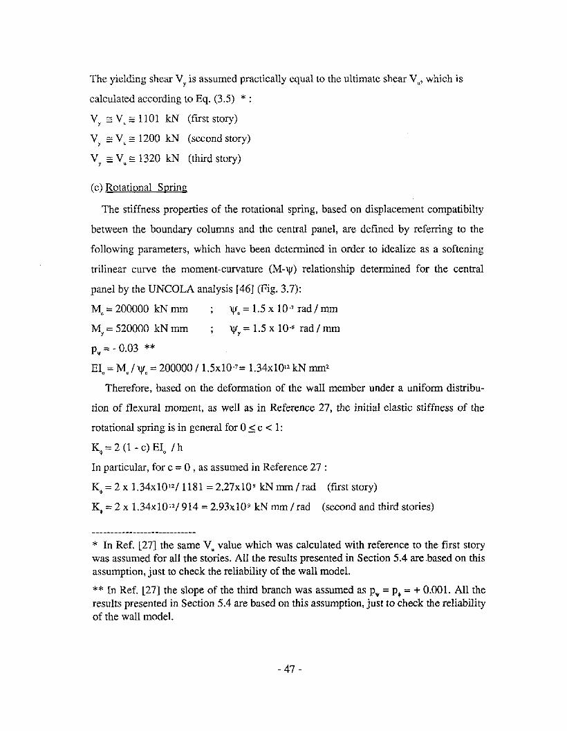
The yielding shear Vy
is assumed practically equal to the ultimate shear Vu ' which is
calculated according to Eq. (3.5) *:
Vy
:::: Vu
:::: 1101 kN (first story)
V :::: V == 1200 kN (second story)y u
V :::: V :::: 1320 kN (third story)y u
(c) Rotational Spring
The stiffness properties of the rotational spring, based on displacement compatibilty
between the boundary columns and the central panel, are defined by referring to the
following parameters, which have been determined in order to idealize as a softening
trilinear curve the moment-curvature (M-\jf) relationship determined for the central
panel by the UNCOLA analysis [46] (Fig. 3.7):
Me = 200000 kN mm \jfe = 1.5 X 10.7 rad / mm
My = 520000 kN mm \jfy = 1.5 X 10⁻⁶ rad / mm
P'l'= - 0.03 **EIo= Me / \jfe = 200000/ 1.5x10-7 = 1.34x10¹² kN mm2
Therefore, based on the deformation of the wall member under a uniform distribu
tion of flexural moment, as well as in Reference 27, the initial elastic stiffness of the
rotational spring is in general for 0 .::; c < 1:
K~ =2 (l - c) EIo / h
In particular, for c = 0 , as assumed in Reference 27 :
K~=2x 1.34x10 12/1181 =2.27x10 9 kNmm/rad (first story)
K~ =2 X 1.34x1012/ 914 =2.93x10 9 kN mm / rad (second and third stories)
* In Ref. [27] the same Vu value which was calculated with reference to the first storywas assumed for all the stories. All the results presented in Section 5.4 are .based on thisassumption, just to check the reliability of the wall model.
** In Ref. [27] the slope of the third branch was assumed as P'l' =p. =+ 0.001. All theresults presented in Section 5.4 are based on this assumption, just to check the reliabilityof the wall model.
- 47-

The ratio of the stiffness of the second and third branches of the skeleton curve of the
rotational spring to the initial elastic stiffness calculated above are, respectively,
a~= a'lf =(My - MJ / [('Vy- 'VJ EIJ ==(520000 - 200000) / [(1.5 - 0.15)10-6 x 1.34x1012 ] =0.17 (all stories)
p~ =P'lf == - 0.03 (p~ =+ 0.001, after Kabeyasawa et al. [27])
- 48-

APPENDIXB
STIFFNESS PROPERTIES OF THE ELEMENTS
CONSTITUTING THE MODEL OF SPECIMENS 5 AND 6
Outside Truss Elements
As (9#5) =9 x 198 == 1782 mm2
A = 279 x 114 - 1782 = 30024 mm2c
Fy = 1782 x 0.482 == 858.924 kN
EsAs =216 x 1782 =384912 kN
Ec Ac =22.1 x 30024 =663530.4 kN
A= (1 /0.90 - 1) 384912/663530.4 == 0.0645
r == (1 + 663530.4 / 384912) / (l + 999 /0.0645) =0.000176
Central Element Springs
(a) Vertical Spring
As (#2 at 102 mm) == 2 x 19 x 31.67 == 1203 mm2
A c =1854 x 114 - 1203 =210153 mm2
Fy = 1203 x 0.507 == 609.921 kN
Es As = 211 x 1203 = 253930 kN
Ec Ac = 22.1 x 210153 = 4644371 kN
A= (l /0.90 - 1) 253930/4644371 == 0.00607
r == (1 + 4644371 /253930) / (l + 999/0.00607) =0.000117
- 49-

(b) Horizontal Spring
Aw = (2412 - 279) x 114 = 243162 mm2
G = 22.1 / [2 (l + 0.2)] = 9.208 kN / mm2
u=1854/2412 v=114/114=1
The shape factor, according to Eq. 3.3b, is X. = 1.32,6
(' = 33.47 MPa
fWh = 507 MPa
PI = 100 x 1782/ [114 x (2412 - 279/2)] = 0.687858
Pwh =2 x 31.67 / (114 x 102) =0.0054472
<Yo = 2 x 299000/ (2412 x 114) = 2.1748 MPa
b = 114mmc
j =7/8 (2412 - 279/2) =1988.438 mm
M / V L = (0.522x2134 + 0.799x3009 + 0.104x2095 + 0.097xl181) / 2412 =
= 1.595 (first floor)
M / V L = (0.522x2134 + 0.799x1828 + O.l04x914) / 2412 = 1.107 (second floor)
M / V L = (0.522x2134 + 0.799x914) /2412 =0.764 (third floor)
Ks =9.208 x 243162/ (1.326 x 1181) = 1429.77 kN / mm (first story)
Ks=9.208 x 243162/ (1.326 x 914) =1847.44 kN / mm (second and third stories)
Us =0.14 + 0.46 x 0.0054472 x 507 / 33.47 =0.178
V e =0.438 X 33.471/2 x 243162 = 616166 N == 616 kN
Vy == Vu == 918 kN (first story)
Vy
== Vu == 1018 kN (second story)
Vy == Vu == 1134 kN (third story)
(c) Rotational Spring
Me = 127000 kN mm
My =590000 kN mm
P'l' =- 0.03
'lfe =0.9x10⁻⁷ rad / mm
'lfy = 1.5xlQ-6 rad / mm
- 50-

Ero = 127000/ 0.9xlO-7 = 1.41xlO12 kN mm2
K~ =2 X 1.41xlO12 / 1181 =2.39x10⁹ kN mm / rad (first story)
K$ =2 X 1.41x1012 / 914 =3.09x10⁹ kN mm / rad (second and third stories)
<X~ = <X1jI =(590000 - 127000) / [(1.5 - 0.09)xlO-6 x 1.41xlO12 ] =0.23 (all stories)
P~ = PIjI = - 0.003 (p, = + 0.001, after Kabeyasawa et al. [27])
- 51 -


TABLES
Preceding page blank- 53-


Table 5.1 - Mechanical Characteristics of Materials (Specimens 3 and 4 [4])
(a) STEEL PROPERTIES (See Fig. 5.6a)
Bar Area E. f fu ESH Eu
Reinforcementy
(mm 2) (MPa) (MPa) (MPa)
Longitudinal (#6) 281.00 211400 444 639 0.012 0.150Boundary
Columns Transverse 16.28 190000 440 479 --- 0.180(gage No.7 wire)
Central Horizontal and 31.67 211000 507 730 0.01 0.12Panel Vertical (#2)
(b) CONCRETE PROPERTIES AT TIME OF TESTING (See Fig. 5.6b)
fe' (average) = (35.2 + 35.4 + 33.8) /3 =34.8 MPa *Ee(average) = 46000 fe' 1/2 (psi) = 3820 fe' 1/2 (MPa) = 3820 X 34.81/2 == 22500 MPa
Unconfined Concrete :
Eo' = 0.003
Eu
' =0.01
Confined Concrete :
k= 1.2
Eo =0.009
E. 3k = 0.053
Eu =0.065
1 psi =6.895x10³ Mpa
1 in =25.4 rnrn
* This value has been calculated as an average of the values corresponding to the threestories of Specimen 3. The same value has been adopted also for Specimen 4, becausethe difference is practically negligible.
- 55-

Table 5.2 - Mechanical Characteristics of Materials (Specimens 5 and 6 [4])
(a) STEEL PROPERTIES (See Fig. 5.6a)
Bar Area E. fy
fu ESH EReinforcement
u
(mm 2) (MPa) (MPa) (MPa)
Longitudinal (#5) 198.00 216000 482 687 0.013 0.148Boundary
Columns Transverse 16.28 190000 440 479 --- 0.180(gage No.7 wire)
Central Horizontal and 31.67 211000 507 730 0.01 0.12Panel Vertical (#2)
(b) CONCRETE PROPERTIES AT TIME OF TESTING (See Fig. 5.6b)
(' (average) =(34.5 + 33.5 + 32.4) / 3 =33.47 MPa *Ee(average) =46000 fe' If}. (psi) =3820 fe' If}. (MPa) =3820 X 33.471f}. == 22100 Mpa
Unconfined Concrete:
Eo' = 0.003
Eu ' =0.01
Confined Concrete :
k= 1.2
Eo =0.009
E. 3K =0.053
Eu =0.065
Units:
1 psi =6.895xlQ-3 MPa1 in =25.4 rom
* This value has been calculated as an average of the values corresponding to the threestories of Specimen 5. The same value has been adopted also for Specimen 6, becausethe difference is practically negligible.
- 56-


FIGURES
- 57-

rh
1
Rigid Beam/
Level m
Rigid Beam
Level m-I
T//{l-c)h
+ch
1
t1v n,,~~ =(c-l) h t1<jJ < 0
r-----J/.....
_ CENTER OFRELATIVEROTATION
(a) Wall Member Model (b) Relationship Between Relative FlexuralDisplacement and Relative Rotation
Fig. 3.1 - R C Wall Model
FORCE, F(tension)
Y" (2D -2F)ye' y--K=K(D/D)a
r c yt m
Dp =Dye + ~ ( D. - DyJ
Fig. 3.2 - Axial-Stiffness Hysteresis Model Proposed by Kabeyasawa et al. [27]
Preceding page blank -59-

F
Y (D , F) M (D"" Fa)r-yt-:.----- --~Kh
I/
//
IIKt
D
~Un= 2KJK,+(D",fDyt-l)K"fK,KJK,+D",fDyt
(a) Limit Value (K1im ) of the Unloading Stiffness K r
1.5
1.0
a=0.9
(Ref. [27])
0.5
--------------K fK =0.50-- - K:f K: = 0.60_
____________------- K,f K, = 0.70_ K,fK,=0.80:::::::=====:============__ K, / K, = 0.90 (Ref. [27])~ =========- ------KJK,=1.00
98765432 10
ll,= Dm IDyl
(b) Limit Value of the Unloading Degradation Parameter aVersus Tensile Ductility Factor J..Lt (Kh / Kc = 0.001)
Fig. 3.3 - Limit Values of the Unloading Stiffness Kr and Degradation Parameter a forthe Axial-Stiffness Hysteresis Model in Fig. 3.2
- 60-

4_-7---
DISPLACEMENT
Fig. 3.4 - Origin-Oriented Hysteresis Model [27]
t=vb f-- a-I
I~!~~IT
I. I. \. g'=uL -I .1£ = (1+u)L/2-----1
L --------
Fig. 3.5 - Geometrical Parameters
- 61 -

ANALYTICAL (UNCOLA ANALYSIS [46])
Satisfied Displacement CompatibilityRegardless of Displacement Compatibility
FLEXURALMOMENT(kNm)
4000
2000
•••• EXPERIMENTAL (VALLENAS ET AL. [4])
ENTIRE WALL -----~==.:-.:--=---:.-:.".:---.:--r\ • .... ,_.::t"_..~.- .. -i • • •
~ ~.._-~ -:-~- ~::::--_-:.- --- ..~.,/=:>-- L BOUNDARY COLUMNS
.. ,/ (Satisfied Displacement Compatibility)
./ ISOLATED CENTRAL PANELt ~ (Regardless of Displacement Compatibility)
~ CENTRAL PANEL~ F(Satisfied Displacement Compatibility).1
~{~~~~--~~ ~~'~~~-'~~~~~~~~~~~'-~-'-~:~'~~=~=~~0.01 0.02 0.03 0.04
CURVATURE (rad 1m)
(a) Flexural Moment Versus Curvature
0.04
CURVATURE (rad I m)
NT = N. + Np = 868 kN
0.030.02
N. ._ ..;= constant _.r ~~::~S~OfDisplacement Compatibility
N. =constant
C_:~,,"od~":~:"'::"~:l:: _/,/------ Np(tension)
,,
0.01
,7- Np (compression)
N. (compression)
1500
1000
500
AXIALFORCE(leN)
(b) Axial Force Versus Curvature
Fig. 3.6 - Experimental and Analytical Curves for the Cross-Section of Specimen 3(Fig.5.3a)
- 62-

FLEXURALMOMENT(kNm)
( M) Lf a... EIo600 '!'y' y /
t\--------
Elo / - ------
400 r-/<:Mol
200 ,I
I,,,
---
0.001 EIo (Ref. [27])
---- ----- --- ---
0.002 0.004 0.006 0.008
CURVATURE (fad/m)
Fig. 3.7 - Idealization of the Moment-Curvature Relationship Obtained for the CentralPanel by UNCOLA Analysis [46] under the Condition of DisplacementCompatibility (alii = 0.17; PIII= - 0.003)
F yielding in tensionI ----
oyielding
~in compression
.:l..--- KK = ct 1 + J.. E A IE A
c c s s
K = Kc
h 1+A. [1 + Ec:c/EsAs -1]
(a) Two-Element-in-Series Model (b) Simplified Force-Deformation Relationship(A. = constant; r = steel-hardening ratio)
Fig. 3.8 - Proposed R C Column Model in Presence of Axial Load Reversals
- 63-

K=c-
KH 0 KH(l-c)h - KH 0 KHch
KJ+I<z+Ky (I<z-KJ)eJ2 0 -K -I<z-K (KJ-KJe/2J y
K,+ -K +,+(K1+I<z)t2f4 KH(c-l) h (KJ-I<z)i /2 -(K1+KJN4
+KH(l-C)2 h2 +KHc(l-c)h2
KH 0 - KHc h
SYMMETRIC KJ+I<z+Ky (I<z-K1)lf2
K,+
+(KJ+I<z)f/4
+ ~c2h2
Fig. 4.1 - Elastic Stiffness Matrix of the Wall Member Model in Fig. 3.1
- 64-

k==OJ..
,-----4 k == k + 1J..
U (k) (u (1) == U )1 1 0
J..~(k) == QT U(k)
J..(JE(k) == (Jo + E (~(k)_ EO)
J..
r(k) == 81
(k) - PI
U1(k+l) == U
1(k) - H r(k), H == {(l-~)~ + ~~}.l
NEXT STEP
U == Displacement Vector
~ == Elastic Strain Vector
(JE == Incremental Elastic Stress Vector
(J == Elastic-Plastic Stress Vector
8 == Structural Reaction Vector
Fig. 4.2 - Iterative Solution Process in the Generic Step of the Analysis
- 65-
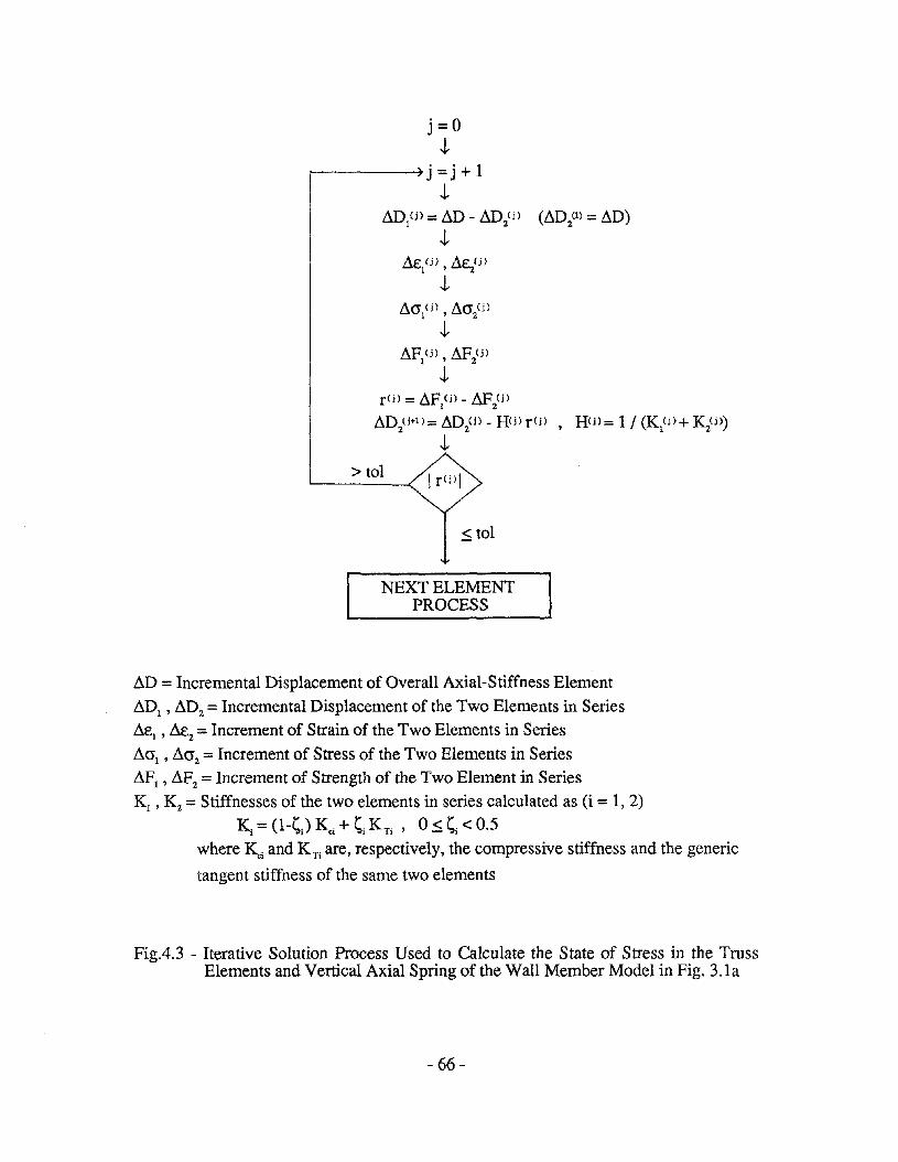
j=O.l.
~---~j=j+1
.l.~Dl(j) = ~D - ~D2(i) (~D2(1) = ~D)
.l.~C' (i) ~e (i)
"'I ' 2
.l.
r(i) = ~F (j) -~ (i)1 2
~D2(i+l)= ~D2(j) - H(j) r(j) , Hi)= 1/ (K1(j) + Kz(j»
.l.> tol Ir(i)1
.$ tol
NEXT ELEMENTPROCESS
~D = Incremental Displacement of Overall Axial-Stiffness Element
~DI ' ~D2 = Incremental Displacement of the Two Elements in Series~el , ~e2 = Increment of Strain of the Two Elements in Series
~al , ~a2 = Increment of Stress of the Two Elements in Series~Fl , ~F2 = Increment of Strength of the Two Element in SeriesK1' K2= Stiffnesses of the two elements in series calculated as (i = 1,2)
Ki = (l-~J Kci + ~i K Ti , 0.:5. ~i < 0.5where Kci and K Ti are, respectively, the compressive stiffness and the generic
tangent stiffness of the same two elements
FigA.3 - Iterative Solution Process Used to Calculate the State of Stress in the TrussElements and Vertical Axial Spring of the Wall Member Model in Fig. 3.1a
- 66-

INSTEP =rSTEP + 1 IASSEM
Tangent Stiffness Matrix: ~,1,
SOLVEIteration Matrix Factorization:
H = {(1-~) KE+ ~ ~}.I
CSTART):L
__l~~--.,ILSW =LSW - 4 I
STRUCTJ, Structural Reaction:
ASSEM SI(k) =81 [uI(k)]
Elastic Stiffness~;~:--s_s_em_bl_a_g_e:_K_E ~_4__~
OUTPUT ~Current State: I r(k) = 81(1<) - PI I
NSTEP, Up PI' sp tJ' a1 J,SOLVE
Displacement Updating:u (k+I) =U (k) - H r(k)
1 1
INPUTGeometrical & Mechanical Data
Initial Conditions: ul ' tl'O'I1
LSW~3
NSTEP=OJ
~ LOADSInitial Load: PI
1STRUCT
Structural Reaction: sJuJ
uo = u 1
Po =P1
SO = Sl
LOADUpdated Load: PI = Po + ~p
Loading NoProcess )..----41 A
Completed?
J. Yes
OUTPUTFinal State: t max, tmin,amax, O'min
Fig. 4.4 - Flow Chart of theComputer Program
- 67 -

76 mm SLAB
FOOTING
O.660m
0.2~ m SQ CQ..UMN
8mmCLEAR BaTH SIDES
VERTICAL CROSS - SECTWJN
76nwn0356mr--
__++-~+-W"U. O.02m THICK
H~r.:==~f~~=rl=====~r~!In, ',II 11 ,OSm IiI, ",," II I
l' lilt II', " II IIii II II I, II .. I~~===.friJ:..:.i,l:.-:.-:.-:.-:.-:.:fr·=-I
j.-~......--- 3.098m ----_afEl.E\ATlON
"'---- 2.388m ----""\76mml 11.880m----I~ 11---'-0 ¢=;:j
0.3051'1'I1 I I It 4.
0914 3Elmmk:::r=====l~$l3l-"t+"'-mr # 2 AT 16 nwnmm EACH WAY AND
EACH FACE4.15Zm .-
0.914m
t:t ,',r--.#·7Gmm~lj
I. 219 m ~-t~G.N. 7t«:lOPS
~I'E IfJ 34mmrr'..
(a) Dimensions and Details of the Framed Wall (Specimens 3 and 4)
76mmSLAB
406m76mmSLAB
LAB
1.016m J 1.016m
O.406-+--c.:;!;::J O.
-- -~
t O.152mSt!Il~I O.ll4mWALlrt
tl[J~I
tJ.J!4! 76mm SLAB
~ ftjl-- O.114m X a.279m COLUMN
95mm ~I WITH 9 ~ 5
L~l-r 0" 095rml II ~ FOOTING
L QJLo
VERTICAL CROSS SECTION
FOOTING
·m-==:;-1
_----+-+----+- WALL 114 mm THICK
2291l'ffl 304mm/52mm 152m", 3j3lmm
3.089m----
ELEVATION
2ATI02nm
t---;:t:===========;;;=-; Wi1~tF
(b) Dimensions and Details of the Rectangular Wall (Specimens 5 and 6)
Fig. 5.1 - Test Walls (Reference 4)
- 68-

<)N
r~-1;.;.;.;.:.;.:.;.;.;.;. __ 6 AT 2745m
20
1.l3m ::::::~:~:~:l!r== J=16 47m
:::;:::;:;:::;:;:::::::::::::::=:=::::::::::.:.:.:.:...•..........~::{:~:~:~:f~:~: 366m.:.:.:.:.:.:.:.:.;.:.' J
v,
I'17 AT 6.lm: =427m
a
o
a
o u
SHEAR WALL
1:
L--- .FLAT SLABl
" u610mmx610mm COL
~
i'B60,mir -u -- --=0-- --1-:.rI
It ] 6.lmn n .-L
I. .~ .1, .16.lm 6.401 m 6.lm
~;~:~~~~~~~;~.,
I~::~:~:::~:~:~:::::
<)N
-FIItF4..........l' •.................'.:.:.:.:.:.:.....:~:~:~:~:~:~:~;i:
i.~~~.L.- .:.:.:.:.::::::::: .~m
:~~??~~? 9 AT 2745m
2B.36m II If;~;~;~;~~~;~;~;~; J=24.7m:.:.:.:.:.:.:.:.:.
:::::;:::::;:::::;::::::;:;:::::~:~
:17 AT 6.ImI =42.7mI
o
o
o
o cSIl
L:--_.P •FLAT SLABl'0610mmx610mm COL
"\,
50Bmmx50Bmm COL
6.lm
"=----Q:-----:o'::----=O --:l-I· .1· ·1· ·1
6.1m 6.401 m 6.1m
$
TYPICAL FLOOR PLAN ELEVATION TYPICAL FLOOR PLAN ELEVATION
(a) Ten-Story Prototype Building (b) Seven-Story Prototype Building
Fig. 5.2 - Prototype Buildings (Reference 4)

t =102nvn
GAGE NO.7 AT I~"
#2 AT 76mn
L =2.388m ---------J(a) Framed Wall (Specimens 3 and 4)
9tt5
, O.279m, / 0.279m-}l" 1.854m ..t-- --I
14m If ~
t ~ ,2.412m T- \( ~9.5
~NO.7 HOOPS /}J 34mm #"2 AT 102mm
0.1
(b) Rectangular Wall (Specimens 5 and 6)
Fig. 5.3 - Detailed Cross-Sections
+-O. l04V
+O.097V
jO.522V
!299 kN
+0: 799V
I I
0.522V!
299 kN!
io.644V
!434 kN
~
I I
0. 644Vl434 kN!
(a) Specimens 3 and 4 (b) Specimens 5 and 6
Fig. 5.4 - Loading Patterns of the Test Walls
-70 -
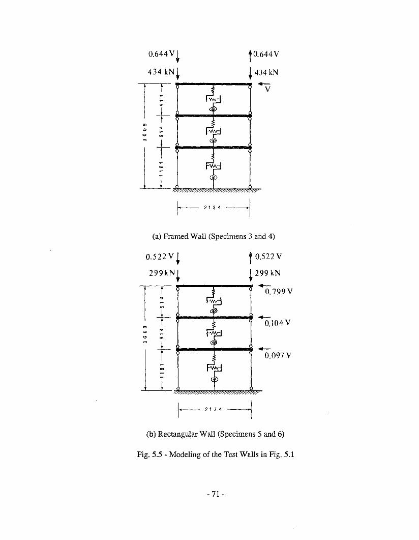
0.644 V + to.644 V
434kN+ +434kN
IT~--.....--.... .--i V
teno ;o '"
(a) Framed Wall (Specimens 3 and 4)
0.522 V + t 0.522 V
299kN+ +299kN
IT,....--.,..---,.. -+--
0.799 V
i _Cl t 0.104 Vo ;o Cl
! ~--...--~.---r- 0.097 V
(b) Rectangular Wall (Specimens 5 and 6)
Fig. 5.5 - Modeling of the Test Walls in Fig. 5.1
- 71 -

IDEALIZATION
(a) Steel
#z. AT 76 mm---t- 1.206m
RECTANGU~AR WA~~
0.254m
I0229rn l!
FRAMED WAll.
0.3k
Cc
0.04 \ 0.06 \E.3k Eu
0> (~}:~~'"""'''UNCONFINED CONCRETE
\.\94m
CONCRETE
0.02
,,,III,I,IIIII
: UNCONFINED CONCRETE
XIIIII,
!sf'c
0.6
1.0
0.8
1.2
0.4
0.2
(b) Concrete
Fig. 5.6 - Constitutive Curves of the Materials
-72 -

• • • •ANALYTICAL (Modified Wall Model)
EXPERIMENTAL (Vallenas et aL [4])
V(kN)
1000
500
---. - .....- ..- ..-.- .-.-.- ....-.-.- - ----------.-.-.-.-..-.-.-.....- ..... '" '-,'---. ... .." .".I •
II •
I.:.I,.
50 100 150
(a) Base Shear Versus Net Top Displacement at the Third Floor
V(kN)
1000
500
..-.-.-........ - .............-.-.,----r-;.-.-.- ..-.-·.....- ~
i·i.II.~I•Il'
D (mm)3t le.ural
50 100
(b) Base Shear Versus Flexural Displacement at the Third Floor
V (kN)~ r _... . -,1000 : •• •
I •I.I
t·i·i·
500
D3Shear (mm)
50
(c) Base Shear Versus Shear Displacement at the Third Floor
Fig. 5.7 - Analytical and Experimental Curves for the Framed Wall under MonotonicLoading (Specimen 3)
-73 -

ANALYTICAL (Modified Wall Model)
• • • • EXPERIMENTAL (Vallenas et al. [4])
-75, ! , I I I I
50I I I
25! I I
,.. - - --- --- ----- ----- .--.-.-, ...... """-/ ... ~".'.I:.,~,.
f
f,
500
1000
V(kN)
(a) Base Shear Versus Net Top Displacement at the Third Floor
V(kN)
1000,r;-;-;--'--·-·-· .\.,.-,•
500 ~
+ o (mm)31le.ural
25 50
(b) Base Shear Versus Flexural Displacement at the Third Floor
1000 ----- --.- ---/ .. \.' .I.
I
I:.
500
03Shear (mm)
25 50
(c) Base Shear Versus Shear Displacement at the Third Floor
Fig. 5.8 - Analytical and Experimental Curves for the Rectangular Wall underMonotonic Loading (Specimen 5)
-74 -

V(kN)
1000
500
-500
-1000 I
03 (11111)FLEX.
V(kN)
1000 j500
-500
)-1000 o (mm)3 SHEAR
-60 -40 -20 0 20 40 60 -80 -60 -40 -20 0 20 40 60
(a) Base Shear Versus FlexuralDisplacement at the Third Floor
(b) Base Shear Versus ShearDisplacement at the Third Floor
ANALYTICAL
V(kN) V(kN)
1000
500
o3SHEAR
(mml
"
I I{ . if/I9~--/ 0' If/
9IA··ffi--I '1/ v 48
1M 12 60
- 500
-1000
o3 FLEXURAL
(mm)
500
1000
-500
-1000
-60 -40 -20 0 20 40 60 - 60 - 40 - 20 0 20 40 60
(c) Base Shear Versus FlexuralDisplacement at the Third Floor
(d) Base Shear Versus ShearDisplacement at the Third Floor
EXPERIMENTAL
Fig. 5.9 - Analytical and Experimental Curves for the Framed Wall under CyclicLoading (Specimen 4)
-75 -
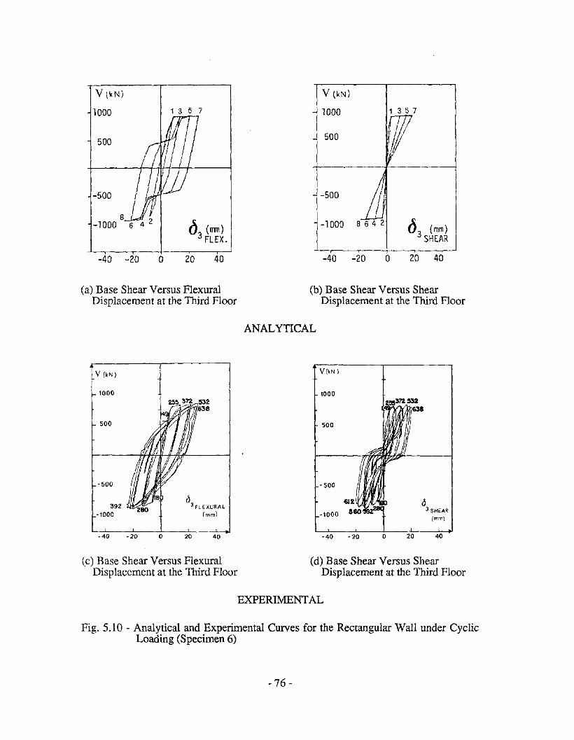
v tkN)
1000
500
-500
8-1000
1 3 5 7
d3
(nm)FLEX.
V (kN)
1000
500
-500
-1000
1 3 5 7
03 (mm)SHEAR
-40 -20 o 20 40 -40 -20 o 20 40
(a) Base Shear Versus FlexuralDisplacement at the Third Floor
V (kN)
1000
(b) Base Shear Versus ShearDisplacement at the Third Floor
ANALYTICAL
V(kN)
1000
<53 FLExuRAL
(mm)
500
-500
'392-1000
·40 -20 o 20 40
500
-500
<5-1000
3 SHEAR
(mm)
-40 - 20 0 20 40
(c) Base Shear Versus FlexuralDisplacement at the Third Floor
(d) Base Shear Versus ShearDisplacement at the Third Floor
EXPERIMENTAL
Fig. 5.10 - Analytical and Experimental Curves for the Rectangular Wall under CyclicLoading (Specimen 6)
-76 -

0,---...,----------------,ooN Z
8r.r,Zwf-<
1512
DISPLACEMENT, D <mm)
000N Z
0H(f)
ZW
~ f-<Z 0
"'"0
~ 0 2 6 8H
~
Wu
'"0~ 0,..l<>:H
~
00:3
6 9 12 15
DISPLACEMENT, D Cmm)
3o- 3
oooN
1
ooo
wu
'"r;: o r---::7.'::t-+---f----f-----f-----i,..l<>:H><<>:
(a) South Truss-Element Response (b) North Truss-Element Response
0
£ 0
::: :3
~
w 0u 0
'" '"0~
,..l<>:H
::20
oo
'"I
Z0HUlZWf-<
- 3 56 8 7
4~~ - t/<-1 t<--2
~J
)
"~ t t0 -3'::4' T"-..7' 5'=6'
-1 o 2 3 4 5 6 7DISPLACEMENT, D Cmm)
(c) Central-Vertical-Spring Response (Loading Process: 0, 1, 1',2,2', .... ,7,7' ,8)
Fig. 5.11 - Analytical Response of the First Story Axial-Stiffness Elements of the WallModel in Fig. 5.5b (Specimen 6)
-77 -

V (kN)
30
EXPERIMENTAL (Vallenas et al. [4])
D3 FLEXURAL
(1l11l)
* '( ANALYTICAL (ANSR - I, Ref. [4])
_._._._. MODIFIEDWALLMODEL
20
,.._.- _.- -'-,
/v·.....·'I.' "I I
i i
i I f}/j I Ii ,(
-1000
-800
- 600
o
-200
-400
(-;I;:"I I
I II I'ofI IIi I
/ I
600
800
1000
I I,/i
il
jI
i
Fig. 5.12 - Analytical and Experimental Curves Representing the Flexural Response ofthe Framed Wall (Specimen 4)
- 78 -

150
100
50
(a) THIRD FLOOR
DISPLACEMENT
COMPONENTS
(n)
.'.'
.'
Third Floor Shear DisplacementComponent :
ANALYTICAL
------- c = 0; Vy =1101 kN (All Stories)
....... c = 0.20; Vy = 1101 kN (All Stories)
_. -'- c = 0.20; Vy = 1101 kN (First Story)Vy = 1200 kN (Second Story)Vy = 1320 kN (Third Story)
(exp.)
• • • • EXPERIMENTAL (Va11enas et al. [4])
50 100 150
0'-0 +03 - 3 flexural 3 s~ar
Shear and Net Top Displacementsat the First Floor:
150
100
50
(b) FIRST FLOOR
DISPLACEMENT
COMPONENTS
(mm)
ANALYTICAL
- --- -- c =0 ; Vy = 1101 leN (All Stories)
........ c = 0,20; Vy = 1101 leN (All Stories)
-'-- c =0.20; Vy =1101 kN (First Story)Vy = 1200 kN (Second Story)Vy =1320 kN (Third Story)
50 100 150
0' =0 +03 3 flexural 3 s~ar
Fig. 5.13 - Comparison of Shear and Flexural Displacement Components Obtained forSpecimen 3 Experimentally (Ref. [4]) and Analytically, by Assuming forthe Modified Wall Model Different Values of the Parameters c and V(Other Data as in APPENDIX A) Y
-79 -

(mm)
(a) After Yielding of the VerticalSpring ( c = 0 ; c = 0.20 ) or theHorizontal Spring (c =0.30 ;c = 0.50) of the Modified WallModel
• • • • EXPERIMENTAL(Vallenas et al. [4])
ANALYTICAL(Modified Wall Model)
---c=O
------- c = 0.20-._. _.- c = 0.30
.......... c=0.50
(b) Before Yielding of the VerticalSpring ( c =0 ; c = 0.20 ) or theHorizontal Spring ( c = 0.30 ;c = 0.50 ) of the ModifiedWall Model (The ExperimentalResults Are Omitted)
40 s:: m01 shear (m )
30
••• • •• •
20
HORIZONTAL-SPRING YIELDING
VERTICAL-SPRING YIELDING \ t
\t../".,/"" 1-",," //
// ./"",," /"'
" ./',;' /' .-.._>:;./' ....."L HORIZONTAL-SPRING YIELDING------_.-, ....-:-- -- '\ ...
/ t ...•..•.•. '.",-- YIELDING OF muss ELEMENT IN TENSION/I .......
;/"'L HORIZONTAL-SPRING CRACKING
30
40
10
20
(mm)
2
2
Fig. 5.14 - First Floor Shear and Flexural Displacement Components for Specimen 3Obtained Experimentally (Ref. [4]) and Analytically, by Assuming for theModified Wall Model Different Values of the Parameter c (Vy = 1101 kNfor All the Stories; Other Data as in APPENDIX A)
- 80-

150
100
50
la) THIRD FLOOR
DISPLACEMENT
COMPONENTS
(mm)/
/
/ '/ "
/ '/ "
/ ./
/ ,.' //~ o· /'
/,' /0// ,,' ./ 3 flexural (exp.)
/ ,,' /' I/''/ ,
/ .,' ./ .//,' /' · -J/~."./ -- .//. /" .. .
/,' ./ • • ./s;: )/<~., -6. /./ V 3 shear (exp,
/ ,'. .... /",... ;.r ./" +"' ....... A .-/.ce· .... - - _.-.- -'-
Third Floor Shear DisplacementComponent:
ANALYTICAL(Modified Wall Model)
------- P~ = 0.. " .... P.= - 0.01- - __ P~ = - 0.02__._.. P. = - 0.03
_ _ _ • EXPERIMENTAL(Vallenas et al. [4])
50 100 150
0'=0 +03 3 flexural 3 shear
Shear and Net Top Displacementsat the First Floor:
ANALYTICAL(Modified Wall Model)
----- - p.= 0....... P~ =-0.01----p.=-O.02-._._ p.= - 0.03
150
100
50
(b) FIRST FLOOR
DISPLAC EMENT
COMPONENTS
(mm)
...-EXPERIMENTAL(Vallenas et al. [4])
50 100 150
Fig. 5.15 - Comparison of Shear and Flexural Displacement Components Obtained forSpecimen 3 Experimentally (Ref. [4]) and Analytically, by AssumingDifferent Values of the Softening Ratio P..1 for the Rotational Spring of theModified Wall Model (Other Data as in ApPENDIX A, Except r =0.001)
- 81 -

150
100
50
(a) THIRD FLOOR
DISPLACEMENT
COMPONENTS
(mm)
.'
(exp.)
(e xp.)
Third Floor Shear DisplacementComponent:
ANALYTICAL(Modified Wall Model)
______ 1.,== 0.0376 (KJKc
== 0.90)_._._._1.,=0.10.........•1.,=0.20
• • • • EXPERIMENTAL(Vallenas et al. [4])
50 100 150
150
100
50
(b) FIRST FLOOR
DISPLACEMENT
COMPONENTS
(mm)
Shear and Net Top Displacementsat the First Floor:
ANALYTICAL(Modified Wall Model)
________ 1.,==0.0376 (KJKc ==0.90)_._._._ 1.,=0.10.......... 1.,=0.20
• • • • EXPERIMENTAL(Vallenas et al. [4])
50 100 150
8' =8 +83 3 fl«uraJ 3 shear
Fig. 5.16 - Comparison of Shear and Flexural Displacement Components Obtained forSpecimen 3 Experimentally (Ref. [4]) and Analytically, by AssumingDifferent Values of the Parameter A for the Outside Truss Elements of theModified Wall Model (Other Data as in APPENDIX A, Except p~ = 0 andr = 0.001)
- 82-

ANALYTICAL(Modified Wall Model)
_0 _0_ A = 0.0376 (K, / K c = 0.90)
'" '" .. A= 0.10_______ A= 0.20
• • • • EXPERIMENTAL(Vallenas et al. [4])
Third Floor Shear DisplacementComponent:
(exp.)
/
()3 flexural
•.. ····~t~,/• ••
(a) THIRD FLOOR
DISPLACEMENT
COMPONENTS
(mm)/
//
//
/// .'
//
//
/ .'/0 ...••. .-. /~
_4- -~.~--- ---- ----,/•
50
150
100
50 100 150
Shear and Net Top Displacementsat the First Floor:
150
100
50
(b) FIRST FLOOR
DISPLACEMENT
COMPONENTS
(mm)
• • • •
ANALYTICAL(Modified Wall Model)
A = 0.0376 (Kt I Kc =0.90)A= 0.10A=0.20
EXPERIMENTAL(Vallenas et ai. [4])
50 100 150
Fig. 5.17 - Comparison of Shear and Flexural Displacement Components Obtained forSpecimen 3 Experimentally (Ref. [4]) and Analytically, by AssumingDifferent Values of the Parameter A for the Outside Truss Elements of theModified Wall Model (Other Data as in APPENDIX A, Except p, =-0.03and r =0.001)
- 83 -

EXPERIMENTAL(VaIlenas et aI. [4])
ANALYTICAL(Modified WaIl Model)
r=O.05r= 0.002
_______ r=O.OOI
• • • •
Third Floor Shear DisplacementComponent:
(exp.)
.'
(a) THIRD FLOOR
DISPLACEMENT
COMPONENTS
(mm) .'
//
.//
./.' ,,/
/// ~
.... /./ ••••• j~./.. ' /' .. ~~~
... / •• • ./ 03 shear (ex p.)• /'. _.-1"''''' ............. ' . .. ..-
.' /. ~~it _t ---- ---- ---~
50
150
100
50 100 150
8'-0 +83 - 3 Dexursl 3 .hear
150
100
50
(b) FIRST FLOOR
DISPLACEMENT
COMPONENTS
en)
Shear and Net Top Displacementsat the First Floor:
ANALYTICAL(Modified WaIl Model)
......... r=O.05_._._._r=O.002________ r =0.001
• • • • EXPERIMENTAL(VaIlenas et aI. [4])
(exp.)
(exp.)
50 100 150
Fig. 5.18 - Comparison of Shear and Flexural Displacement Components Obtained forSpecimen 3 Experimentally (Ref. [4]) and Analytically by AssumingDifferent Values of the Parameter r for All the Axial-Stiffness Elements ofthe Modified Wall Model (Other Data as in APPENDIX A, Except p~
== - 0.03)
- 84-

Th=1
1
11<1>CUNCOLA)
a) Flexural Deformations:
_______ UNCOLA AnalysisI '- Wall Model (c = 0),
..... 11<1> (Wall Model) = 11<1> (UNCOLA) / 2
yielding of the truss element in tension A, =' 0.01
[
yielding of the vertical spring __f-. -- ....... K K 0 90)-- A, = 0.0376 ( J 0 = .
__ -- -- A, =0.05----- .--- . --___ ..... ' .' ----_--ill.. ' ....---....----
. . ;.. - _..... --_.i _~------- BOUNDARY COLUMN CONTRIBUfION/ ~ Modified Wall Model (Different Values of A, for the Outside Truss Elements)
Modified Wall Model (Adjusted Yield Strength of Vertical Spring: F,=' 475 kN)UNCOLA Analysis (Under Displacement Compatibility)
FLEXURALMOMENT(kNm)
4000
2000yielding of the rotational spring
CENTRAL PANEL CONTRIBUfION,.---- Modified Wall Model (p.= 0.03)
UNCOLA Analysis (Under Displacement Compatibility) CURVATURE SCALE (rad/m)
WALL MODEL
0.004
I0.008
0.008UNCOLA ANALYSIS
AXIALFORCE(kN)
2000
1000
(b) Flexural Moment Versus Curvature
r---- Modified Wall Model (A, = 0.0376 for the Outside Truss Elements)Modified Wall Model (Adjusted Yield Strength of Vertical Spring: F, = 475 kN)UNCOLA Analysis (Under Displacement Compatibility)
,--Np (tension)
NB (compression)CURVATURE SCALE (rad/m)
WALL MODEL
0.004
i0.008
0.008
0.016
UNCOLA ANALYSIS ..
(c) Axial Force Versus Curvature
Fig. 5.19 - Flexural Deformations and Analytical Curves for a Wall Member of UnitHeight under Uniform Flexural Moment (Cross-Section and MechanicalProperties of Specimen 3)
- 85-

EARTHQUAKE ENGINEERING RESEARCH CENTER REPORT SERIES
EERC repom are available from the National Information Service for Earthquake Engineering(NISEE) and from the National Technical InformationService(NTIS). Numbers in parentheses are Accession Numbers assigned by the National Technical Information Service; these are followed by a price code.Contact NTIS. 5285 Port Royal Road. Springfield Virginia. 22161 for more information. Reports without Accession Numbers were not available from NTISat the time of printing. For a current complete list of EERC reports (from EERC 67-1) and availablity information. please contact University of California.EERC. NISEE. 130 I South 46th Street. Richmond. California 94804.
UCB/EERC-80/0 I
UCB/EERC-80/02
UCB/EERC-80/03
UCB/EERC-80104
UCB/EERC-80/05
UCB/EERC-80/06
'Earthquake Response of Concrete Gravity Dams Including HYdrodynamic and Foundation Interaction Effects.' by Chopra. AX.,Chakrabarti. P. and Gupta. S., January 1980. (AD-AOS7297)A10.
'Rocking Response of Rigid Blocks to Earthquakes: by Yim. C.S., Chopra. A.K. and Penzien. J.. January 1980, (PB80 166 002)A04.
"Optimum Inelastic Design of Seismic-Resistant Reinforced Concrete Frame Structures: by Z3gajeski, S.W. and Bertero. V.V.. January1980. (PB80 164 635)A06.
"Effects of Amount and Arrangement of Wall-Panel Reinforcement on Hysteretic Behavior of Reinforced Concrete Walls." by lIiya. R.and Bertero. V. V., February 19S0. (PB8l 122 525)A09.
"Shaking Table Research on Concrete Dam Models: by Niwa. A. and Clough, R. W., September 1980, (PB81 122 36S)A06.
-The Design of Steel Energy-Absorbing Restrainers and their Incorporation into Nuclear Power Plants for Enhanced Safety (VoIla):Piping with Energy Absorbing Restrainers: Parameter Study on Small Systems," by Powell. G.H., Oughourlian, C. and Simons. J•• June19S0.
UCB/EERC-SO/21
UCB/EERC-80/14
UCB/EERC-80/07
UCB/EERC-80/18
'Inelastic Torsional Response of Structures Subjected to Earthquake Ground Motions: by Yamazaki. Y .. April 19S0. (PBS I 122327)A08.
'Study of X-Braced Steel Frame Structures under Earthquake Simulation: by Ghanaat, Y., April 1980. (PB81 122 335)AII.
"Hybrid Modelling of Soil-Structure Interaction.' by Gupta. S.. Lin. T.W. and Penzien, J., May 19S0. (PBSI 122 319)A07.
'General Applicability ofa Nonlinear Model of a One Story Steel Frame: by Sveinsson. B.I. and McNiven, H.D.• May 19S0. (PBSI124877)A06.
"A Green-Function Method for Wave Interaction with a Submerged Body: by Kioka. W.• April 1980, (PBSI 122 269)A07.
-Hydrodynamic Pressure and Added ~ass for Axisymmetric Bodies.: by NiIrat, F., May 1980. (PBSI 122 343)A08.
"Treatment of.Non-Linear Drag'Forces Acting on Offshore Platforms,~ by Dao; B.V. aad· Penzien. J., May 1980, (pB81 153 413)A07.
"2D Plane/Axisymmetric Solid Element (Type 3-Elastic or Elastic-Perfectly Plastic)for the ANSR-II Program,' by Mondkar, D.P. andPowelL G.H., July 19S0, (PB81 122 350)A03. .
"A Response Spectrum Method for Random Vibrations: by Der Kiureghian. A., June 19S1, (PBSI 122 301)A03.
"Cyclic Inelastic Buckling of Tubular Steel Braces: by Zayas. V.A., Popov, E.P. and Martin. S.A., June 1981, (PB81 124 8S5)AI0.
"Dynamic Response of Simple Arch Dams Including Hydrodynamic Interaction,- by Porter. C.S. and Chopra, A.K.. July 1981. (PBS I124 OOO)A13.
"Experimental Testing of a Friction Damped Aseismic Base Isolation System with Fail-Safe Characteristics: by Kelly, J.M., Beucke.K.E. and Skinner. M.S., July 19S0, (PBSI 14S 595)A04.
"The Design of Steel Energy-Absorbing Restrainers and their Incorporation into Nuclear Power Plants for Enhanced Safety (Vol.! B):Stochastic Seismic Analyses of Nuclear Power Plant Structures and Piping Systems Subjected to Multiple Supported Excitations." byLee. M.e. and Penzien, J., June 19S0. (PB82 201 872)A08.
"The Design of Steel Energy-Absorbing Restrainers and their Incorporation into Nuclear Power Plants for Enhanced Safety (Vol IC):Numerical Method for Dynamic Substructure Analysis: by Dickens. J.M. and Wilson, E.L, June 1980.
"The Design of Steel Energy-Absorbing Restrainers and their Incorporation into Nuclear Power Plants for Enhanced Safety (Vol 2):Development and Testing of Restraints for Nuclear Piping Systems,- by Kelly, J.M. and Skinner. M.S.. June 19S0.
"3D Solid Element (Type 4-Elastic or Elastic-Perfectly.Plastic) for the ANSR-II Program: by Mondkar, D.P. and Powell, G.H., July19S0, (PB8 I 123 242)A03.
"Gap-Friction Element (Type 5) for the Ansr-II Program: by Mondkar, D.P. and Powell, G.H., July 19S0, (PB81 1222S5)A03.
"U-Bar Restraint Element (Type II) for the ANSR-II Program,' by Oughourlian, e. and Powell. G.H., July 1980. (PBS I 122 293)A03.
"Testing of a Natural Rubber Base Isolation System by an Explosively Simulated Earthquake: by Kelly, J.M.. August 19S0, (PBSI 201360)A04.
UCB/EERC·80/26 "Input Identification from Structural Vibrational Response: by Hu. Y., August 19S0. (PBSI 152 30S)A05.
UCB/EERC-SO/27 "Cyclic Inelastic Behavior of Steel Offshore Structures: by Zayas. V.A.. Mahin, S.A.. and Popov. E.P., August 1980. (PB81 196IS0)Al5.
UCB/EERC-SO/23
UCB/EERC-SO/24
UCB/EERC-SO/25
UCB/EERC-80/22
UCB/EERC-80/20
UCB/EERC-80/I5
UCB/EERC·80/16
UCB/EERC·80117
UCB/EERC-SO/19
UCB/EERC-80/0S
UCB/EERC-80/09
UCB/EERC-SOI1 0
UCB/EERC-SOlll
UCB/EERC-80112
'UCB/EERC-SOIl3
UCB/EERC-80/28 "Shaking Table Testing of a Reinforced Concrete Frame with Biaxial Response: by Oliva. M.G.. October 1980, (PB81 154 304)AI0.
UCB/EERC-80129 "Dynamic Properties of a Twelve-Story Prefabricated Panel Building," by Bouwkamp, J.G., Kollegger. J.P. and Stephen, R.M.. October19S0, (PB82 13S 777)A07.
UCB/EERC-80/30 "Dynamic Properties of an Eight-Story Prefabricated Panel Building: by Bouwkamp. J.G., Kollegger, J.P. and Stephen, R.M., October1980, (PB81 200 313)A05.
UCB/EERC-80/3l 'Predictive Dynamic Response of Panel Type Structures under Earthquakes: by Kollegger, J.P. and Bouwkamp. J.G., October 19S0.(PBS! 152 316)A04.
UCB/EERC-SO/32 'The Design of Steel Energy-Absorbing Restrainers and their Incorporation into Nuclear Power Plants for Enhanced Safety (Vol 3):Testing of Commercial Steels in Low-Cycle Torsional Fatique: by Spanner. P., Parker. E.R., Jongewaard, E. and Dory, M., 19S0.
Preceding page,blank - 87-

UCB/EERC-80/33 "The Design of Steel Energy-Absorbing Restrainers and their Incorporation into Nuclear Power Plants for Enhanced Safety (Vol 41:Shaking Table Tests of Piping Systems with Energy"Absorbing Restrainers." by Stiemer. S.F. and Godden. W.G.. September 1980.(PB8:? 201 880)A05.
UCB/EERC-80/34 "The Design of Steel Energy-Absorbing Restrainers and their Incorporation into Nuclear Power Plants for Enhanced Safety (Vol 5):Summary Repon: by Spencer. P.. 1980.
UCB/EERC-80/35 "Experimental Testing of an Energy-Absorbing Base Isolation System: by Kelly. J.M.• Skinner. M.S. and Beucke. K.E.. October 1980.(PB81 154 072)A04.
UCB/EERC-80/36 -Simulating and Analyzing Artificial Non-Stationary Eanh Ground Motions: by Nau. R.F.. Oliver. R.M. and Pister. K.S.. October1980. (PB81 153 397)A04.
UCB/EERC"80/37 "Eanhquake Engineering at Berkeley - 1980: by. September 1980. (PB81 205 674)A09.
UCB/EERC-80/38 "Inelastic Seismic Analysis of Large Panel Buildings." by Schricker. V. and Powell. G.H.. September 1980. (PB81 154 338)1\ 13.
UCB/EERC-80/39 "Dynamic Response of Embankment. Concrete-Gavity and Arch Dams InclUding HydrodynamIC Interation." by Hall. J.F. and Chopra.AX. October 1980. (PB81 152 324)AII.
UCB/EERC"80/40 "Inelastic Buckling of Steel Struts under Cyclic Load Reversal.." by Black. R.G.• Wenger. W.A. and Popov. E.P.. October 1980. (PB81154312)A08.
UCB/EERC·81/11
UCB/EERC-81/07
UCB/EERC-81/13
UCB/EERC-81/06
-Influence of Site Characteristics on Buildings Damage during the October 3.1974 Lima Earthquake." by Repetto. P.. Arango. I. andSeed. H.B.. September 1980. (PB81 161 739)A05.
"Evaluation of a Shaking Table Test Program on Response Behavior of a Two Story Reinforced Concrete Frame: by Blonde!. J.M..Clough. R.W. and Mahin. S.A., December 1980. (PB82 196 544)AI1.
"Modelling of Soil-Structure Interaction by Finite and Infinite Elements." by Medina. F.. December 1980. (PB8l 229 270)A04.
"Control of Seismic Response of Piping Systems and Other Structures by Base Isolation: by Kelly, J.M.. January 1981, (PB81 200735)A05.
"OPTNSR- An Interactive Software System for Optimal Design of Statically and Dynamically Loaded Structures with NonlinearResponse: by Bhatti, M.A.. Ciampi. V. and Pister. K.S.. January 1981, (PB81 218 851)A09.
"Analysis ofl-acal Variations in Free Field Seismic Ground Motions: by Chen. J.-c.. Lysmer. J. and Seed. H.B.. January 1981. (ADA099508)AI3.
-Inelastic Structural Modeling of Braced Offshore Platforms for Seismic Loading: by zayas. VA.. Shing. P."S.B.. Mahin. S.A. andPopov. E.P.. January'198l, (PB82 138 777)A07.
"Dynamic Response of Light Equipment in Structures." by Der Kiureghian. A.. Sackman. J.L. and Nour-Omid. B.. April 1981. (PB81218 497)A04.
-Preliminary Experimental Investigation of a Broad Base Liquid Storage Tank." by Bouwkamp. J.G., Kollegger. J.P. and Stephen. R.M..May 1981. (PB8:? 140 385)A03.
"The Seismic Resistant Design of Reinforced Concrete Coupled Structural Walls: by Aktan. A.E. and Benero. V.V.• June 1981. (PB82113 358)AII.
"Unassigned: by Unassigned. 1981.
"Experimental Behavior of a Spatial Piping System with Steel Energy Absorbers Subjected to a Simulated Differential Seismic Input." byStiemer. S.F.: Godden. W.G. and Kelly, J.M.• July 1981, (PB82 201 898)A04.
"Evaluation of Seismic Design Provisions for Masonry in the United States: by Sveinsson. B.L Mayes. R.L. and McNiven. H.D..August 1981. (PB82 166 075)A08.
"Two-Dimensional Hybrid Modelling of Soil-Structure Interaction: by Tzong. T.·l., Gupta" S. and Penzien. 1.. August 1981. (PB82 142118)A04.
-Studies on Effects of Infills in Seismic Resistant RIC Construction: by Brokken. S. and Benero. V.V., October 1981, (PB8:! 166190)A09.
"Linear Models to Predict the Nonlinear Seismic Behavior of a One-Story Steel Frame: by Valdimarsson. H.. Shah. A.H. andMcNiven. H.D.• September 1981. (PB82 138 793)A07.
"TLUSH: A Computer Program for the Three-Dimensional Dynamic Analysis of Earth Dams.' by Kagawa. T.. Mejia. L.H.• Seed. H.B.and Lysmer. J., September 1981. (PB82 139 940)A06.
"Three Dimensional Dynamic Response Analysis of Eanh Dams: by Mejia. L.H. and Seed. H.B.. September 1981. (PB82 137 274)AI2.
"Experimental Study of Lead and E1astomeric Dampers for Base Isolation Systems: by Kelly, J.M, and Hodder. S.B.• October 1981.(PB82 166 (82)A05.
"The Influence of Base Isolation on the Seismic Response of Light Secondary Equipment: by Kelly. J.M.• April 1981, (PB82 255266)A04.
"Studies on Evaluation of Shaking Table Response Analysis Procedures: by Blondet. J, M.. November 1981, (PB82 197 278)AIO.
"DELlGHT.STRUCT: A Computer-Aided Design Environment for Structural Engineering, - by Balling, R.J.. Pister. K.S. and Polak. IE..December 1981. (PB82 218 496)A07.
UCB/EERC-81/20 "Optimal Design of Seismic-Resistant Planar Steel Frames: by Balling. RJ .. Ciampi. V. and Pister. K.S., December 1981. (PB82 220179)A07.
UCB/EERC-811l8
UCB/EERC-81/19
UCB/EERC-81/17
UCB/EERC-81/14
UCB/EERC-811 I2
UCB/EERC"81/15
UCB/EERC-81/16
UCB/EERC-81/1O
UCB/EERC-81/05
UCB/EERC-81/04
UCB/EERC-81/02
UCB/EERC"80/43
UCB/EERC-81/01
UCB/EERC-81/08
UCB/EERC-81/09
UCB/EERC-80/42
UCB/EERC"80/4 I
UCB/EERC-81/03
UCB/EERC-82/01 "Dynamic Behavior of Ground for Seismic Analysis of Lifeline Systems." by Sato. T. and Der Kiureghian. A.. January 1982. (PB82 218926)A05.
UCB/EERC-82/02 'Shaking Table Tests of a Tubular Steel Frame Model." by Ghanaat. Y. and Clough. R.W.. January 1982, (PB82 220 161)A07.
- 88-

UCB/EERC-82/03
UCB/EERC-82/04
UCB/EERC-82/05
UCB/EERC-82/06
UCB/EERC-82/07
UCB/EERC-82/08
UCB/EERC-82/09
UCB/EERC-82/10
lJCB/EERC-82/11
UCB/EERC-82/12
lJCB/EERC-82/13
lJCB/EERC-82/14
UCB/EERC-82/15
lJCB/EERC-82/16
UCB/EERC-82/17
lJCB/EERC-82118
lJCB/EERC-82!l9
UCB/EERC-82/20
UCB/EERC-82/21
lJCB/EERC-82/22
lJCB/EERC-82/23
UCB/EERC-82/24
UCB/EERC-82/25
UCB/EERC-82/26
lJCB/EERC-82/27
UCB/EERC-83/0 I
UCB/EERC-83/02
UCB/EERC-83/03
lJCB/EERC-83/04
UCB/EERC-83/05
lJCB/EERC-83/06
UCB/EERC-83/07
lJCB/EERC-83/08
UCB/EERC-83/09
UCB/EERC-83/1O
UCB/EERC-83111
UCB/EERC-83/12
UCB/EERC-83/13
-Behavior of a Piping System under Seismic Excitation: Experimental Investigations of a Spatial Piping System supported by Mechanical Shock Arrestors.' by Schneider. S.. Lee. H.-M. and Godden. W. G.. May 1982. (PB83 172 544)A09.
-New Approaches for the Dynamic Analysis of Large Structural Systems.- by Wilson. E.L.. June 1982, (PB83 148 080)A05.
-Model Study of Effects of Damage on the Vibration Properties of Steel Offshore Platforms: by Shahrivar. F. and Bouwkamp, J.G..June 1982. (PB83 148 742)A10.
-States of the Art and Pratice in the Optimum Seismic Design and Analytical Response Prediction of RIC Frame Wall Structures, - byAktan. A.E. and Bertera. V.V., July 1982, (PB83 147 736)A05.
-Further Study of the Earthquake Response of a Broad Cylindrical Liquid-Storage Tank Model: by Manos. G.c. and Clough, R.W..July 1982. (PB83 147 744)Al I.
-An Evaluation of the Design and Analytical Seismic Response of a Seven Story Reinforced Concrete Frame: by Charney, F.A. andBertero. V.V .. July 1982. (PB83 157 628)A09.
-Fluid-Structure Interactions: Added Mass Computations for Incompressible Fluid: by Kuo. J.S.-H., August 1982, (PB83 156 281)A07.
-Joint-Opening Nonlinear Mechanism: Interface Smeared Crack Model: by Kuo, J.S.-H .. August 1982, (PB83 149 195)A05.
"Dynamic Response Analysis of Techi Dam,- by Clough. R.W.. Stephen. R.M. and Kuo. J.S.-H., August 1982, (PB83 147 496)A06.
"Prediction of the Seismic Response of RIC Frame-Coupled Wall Structures," by Aktan. A.E., Bertero. V.V. and Piazzo, M., August1982. (PB83 149 203)A09.
'Preliminary Report on the Smart I Strong Motion Array in Taiwan," by B(llt, B.A., Loh. C.H., Penzien. J. and Tsai, Y.B.. August1982. (PB83 159 400)AIO.
"Shaking-Table Studies of an Eccentrically X-Braced Steel Structure," by Yang, M.S., September 1982, (PB83 260 778)AI2.
"The Performance of Stairways in Earthquakes: by Roha. C., Axley, J .W. and Bertero, V.V., September 1982, (PB83 157 693)A07.
"The Behavior of Submerged Multiple Bodies in Eanhquakes: by Liao. W.-G., September 1982, (PB83 l58 709)A07.
"Effects of Concrete Types and Loading Conditions on Local Bond-Slip Relationships,' by Cowell, A.D., Popov, E.P. and Benero, V.V.,September 1982. (PB83 153 577)A04.
"Mechanical Behavior of Shear Wall Vertical Boundary Members: An Experimental Investigation: by Wagner, M.T. and Benero, V.V.,October 1982. (PB83 159 764)A05.
"Experimental Studies of Multi-support Seismic Loading on Piping Systems," by Kelly, J.M. and Cowell, A.D., November 1982.
"Generalized Plastic Hinge Concepts for 3D Beam-Column Elements," by Chen, P. F.-S. and Powell, G.H., November 1982, (PB83 247981)A13.
"ANSR-Il: General Computer Program for Nonlinear Structural Analysis," by Oughourlian. C.V. and Powell, G.H., November 1982.(PB83 251 330)AI2.
'Solution Strategies for Statically Loaded Nonlinear Structures," by Simons, J.W. and Powell, G.H., November 1982, (PB83 197970)A06.
"Analytical Model of Defonned Bar Anchorages under Generalized Excitations,' by Ciampi, V.. Eligehausen, R., Bertero, V.V. andPopov, E.P., November 1982. (PB83 169 532)A06.
"A Mathematical Model for the Response of Masonry Walls to Dynamic Excitations, - by Sucuoglu, H., Mengi, Y. and McNiven, H.D.,November 1982, (PB83 169011)A07.
-Earthquake Response Considerations of Broad Liquid Storage Tanks: by Cambra, F.J., November 1982, (PB83 251 215)A09.
"Computational Models for Cyclic Plasticity, Rate Dependence and Creep: by Mosaddad, B. and Powell, G.H., November 1982, (PB83245 829)A08.
'Inelastic Analysis of Piping and Tubular Structures,' by Mahasuverachai, M. and Powell, G.H.. November 1982, (PB83 249 987)A07.
"The Economic Feasibility of Seismic Rehabilitation of Buildings by Base Isolation,' by Kelly, J.M., January 1983, (PB83 197 988)A05.
"Seismic Moment Connections for Moment-Resisting Steel Frames.: by Popov, E.P.. January 1983, (PB83 195 412)A04.
"Design of Links and Beam-ta-Column Connections for Eccentrically Braced Steel Frames,' by Popov, E.P. and Malley, J.O., January1983. (PB83 194 811)A04.
'Numerical Techniques for the Evaluation of Soil-Structure Interaction Effects in the Time Domain,- by Bayo, E. and Wilson, E.L..February 1983, (PB83 245 605)A09.
-A Transducer for Measuring the Internal Forces in the Columns of a Frame-Wall Reinforced Concrete Structure: by Sause, R. andBertero, V.V.. May 1983. (PB84 119 494)A06.
'Dynamic Interactions Between Floating Ice and Offshore Structures: by Croteau. P.. May 1983. (PB84 119 486)AI6.
"Dynamic Analysis of Multiply Tuned and Arbitrarily Supported Secondary Systems: by Igusa, T. and Der Kiureghian, A., July 1983.(PB84 118 272)AII.
,A Laboratory Study of Submerged Multi-body Systems in Eanhquakes: by Ansari. G.R., June 1983, (PB83 261 842)AI7.
'Effects of Transient Foundation Uplift on Earthquake Response of Structures," by Yim, c.-S. and Chopra. A.K., June 1983, (PB83 261396)A07.
"Optimal Design of Friction-Braced Frames under Seismic Loading,' by Austin, M.A. and Pister, K.S., June 1983, (PB84 119 288)A06.
"Shaking Table Study of Single-Story Masonry Houses: Dynamic Performance under Three Component Seismic Input and Recommen,dations," by Manos, G.C.. Clough, R.W. and Mayes. R.L., july 1983. (UCB/EERC-831Il)A08.
"Experimental Error Propagation in Pseudodynamic Testing," by Shiing, P.B. and Mahin, S.A., June 1983, (PB84 119 270)A09.
"Experimental and Analytical Predictions of the Mechanical Characteristics of a lIS,scale Model of a 7-story RIC Frame-Wall BuildingStructure: by Aktan, A.E.. Benero, V.V., Chowdhury, A.A. and Nagashima, T., June 1983, (PB84 119 213)A07.
- 89-

UCB/EERC-83114 'Shaking Table Tests of Large-Panel Precast Concrete Building System Assemblages: by Oliva. M.G. and Clough. R.W.. June 1982..(PB86 110 210/AS)AI1.
UCB/EERC-83/15 -Seismic Behavior of Active Beam Links in Eccentrically Braced Frames: by Hjelmstad, K.D. and Popov. E.P.. July 1983. (PB84 119676)A09.
UCB/EERC-83/16 'System Identification of Structures with Joint Rotation: by Dimsdale. J.S.. July 1983. (PB84 192 210)A06.
UCB/EERC-83/17 "Construction of Inelastic Response Spectra for Single-Degree-of.Freedom Systems: by Mahin. S. and Lin. J.. June 1983, (PB84 208 .834)A05.
UCB/EERC-83/18 -Interactive Computer Analysis Methods for Predicting the Inelastic Cyclic Behaviour of Structural Sections: by Kaba. S. and Mahin.S.. July 1983. (PB84 192 012)A06.
UCB/EERC-83/19 "Effects of Bond Deterioration on Hysteretic Behavior of Reinforced Concrete Joints. - by Filippou. F.e.. Popov. E.P. and Benero. V.V..August \983. (PB84 192 020)A 10.
UCB/EERC-83/20 "Analytical and Experimental Correlation of Large-Panel Precast Building System Performance.' by Oliva. M.G.• Clough. R. W.• VelkCtv.M. and Gavrilovic. P.. November 1983.
UCB/EERC-83/21 -Mechanical Characteristics of Materials Used in a 1/5 Scale Model ofa 7-Story Reinforced Concrere Test Structure: by Benero. V.V..Aktan. A.E.• Harris. H.G. and Chowdhury, A.A., October 1983, (PB84 193 697)A05.
UCB/EERC-83/22 -Hybrid Modelling of Soil-Structure Interaction in Layered Media." by Tzong, T.-J. and Penzien. J•• October 1983, (PB84 192 I78)A08.
tJCB/EERC-83/23 "Local Bond Stress-Slip Relationships of Deformed Bars under Generalized Excitations.' by Eligehausen. R.• Popov. E.P. and Benero.V.V.. October 1983, (PB84 192 848)A09.
UCB/EERC-83/24 "Design Considerations for Shear Links in Eccentrically Braced Frames: by Malley, J.O. and Popov. E.P., November 1983. (PB84 1.92186)A07.
VCB/EERC-84/01 "Pseudodynamic Test Method for Seismic Performance Evaluation: Theory and Implementation: by Shing, P.-S.B. and Mahin. SA.January 1984. (PB84 190 644)A08.
VCB/EERC·84/02 "Dynamic Response Behavior of Kiang Hong Dian Dam: by Clough, R.W.• Chang, K.-T., Chen. H.-Q. and Stephen. R.M., April 1984.(PB84 209 402)A08.
UCB/EERC-84/03 "Refined Modelling of Reinforced Concrete Columns for Seismic Analysis: by Kaba, S.A. and Mahin, SA, April 1984, (PB84 234384)A06.
VCB/EERC-84/04 "A New Floor Respons~ Spectrum Method for Seismic Analysis of Multiply Supported Secondary Systems." by Asfura, A. and DerKiureghian. A., June 1984, (PB84 239 417)A06.
UCB/EERC-84/05 "Earthquake Simulation Tests and Associated Studies of a 1/5th-scale Model of a 7-Story RIC Frame-Wall Test Structure: by Ber,ero.V.V., Aktan. A.E., Charney, F.A. and Sause. R., June 1984, (PB84 239 409)A09.
VCB/EERC-84/06'RlC Structural Walls: Seismic Design for Shear: by Aktan. A.E. and Bertero, V.V., 1984.
VCB/EERC-84/07 "Behavior of Interior and Exterior Rat-Plate Connections subjected to Inelastic Load Reversals: by Zee, H.L. and Moehle. J.P.. August1984, (PB86 117 629/AS)A07.
VCB/EERC-84/08 "Experimental Study of the Seismic Behavior of a Two-Story Rat-Plate Structure: by Moehle. J.P. and Diebold. J.W., August" 984.(PB86 122 553/AS)AI2.
VCB/EERC-84/09 "Phenomenological Modeling of Steel Braces under Cyclic Loading: by Ikeda, K., Mahin. SA and Dermitzakis, S.N., May 1984, (PB86132 198/AS)A08.
UCB/EERC-84/l0 -Earthquake Analysis and Response of Concrete Gravity Dams," by Fenves, G. and Chopra, A.K., August 1984, (PB85 193902/AS)Al1.
VCB/EERC-84/11 "EAGD-84: A Computer Program for Earthquake Analysis of Concrete Gravity Dams," by Fenves. G. and Chopra, A.K., August 1984.(PB85 193 613/AS)A05.
VCB/EERC-84/12 "A Refined Physical Theory Model for Predicting the Seismic Behavior of Braced Steel Frames: by Ikeda. K. and Mahin. S.A., July1984, (PB85 191 450/AS)A09.
UCB/EERC-84/13 "Eanhquake Engineering Research at Berkeley - 1984: by, August 1984, (PB85 197 34I/AS)AIO.
UCB/EERC-84/14 -Moduli and Damping Factors for Dynamic Analyses of Cohesionless Soils: by Seed. H.B., Wong, R.T.. Idriss. I.M. and Tokimat:;u. K..September 1984. (PB85 191 468/AS}A04.
VCB/EERC-84/l5 "The Influence of SPT Procedures in Soil Liquefaction Resistance Evaluations." by Seed. H.B.. Tokimatsu. K.. Harder. L.F. and Chung.R.M.. October 1984. (PB85 191 732/AS)A04.
VCB/EERC-84/16 "Simplified Procedures for the Evaluation of Settlements in Sands Due to Earthquake Shaking: by Tokimatsu. K. and Seed. H,B..October 1984. (PB85 197 887/AS)A03.
VCB/EERC-84/l7 'Evaluation of Energy Absorption Characteristics of Bridges under Seismic Conditions," by Imbsen. R.A. and Penzien. J., November1984.
VCB/EERC-84/18 "Structure-Foundation Interactions under Dynamic Loads: by Liu. W.D. and Penzien, J., November 1984. (PB87 124 889/AS)A l1.
VCB/EERC-84/19 -Seismic Modelling of Deep Foundations," by Chen. c.-H. and Penzien, J., November 1984, <PB87 [24 798/AS)A07.
VCB/EERC-84/20 "Dynamic Response Behavior of Quan Shui Dam: by Clough, R.W., Chang, K.-T", Chen, H."Q.• Stephen. R.M.. Ghanaat. Y. and Qi.J.-H., November 1984. (PB86 115 I77/AS)A07.
UCB/EERC-85/01 "Simplified Methods of Analysis for Earthquake Resistant Design of Buildings: by Cruz, E.F. and Chopra. A.K.. February 1985, (PB86I I2299/AS)A I2.
VCB/EERC-85/02 'Estimation of Seismic Wave Coherency and Rupture Velocity using the SMART I Strong-Motion Array Recordings," by Abrahamson.N.A.• March 1985, (PB86 214 343)A07.
- 90-

UCBfEERC·85/09
UCBfEERC-85/03
UCBfEERC-85f04
UCB/EERC-85f05
UCBfEERC-85/06
UCBfEERC-85f07
UCBfEERC-85f08
'Dynamic Properties of a Thirty Story Condominium Tower Building,' by Stephen. R.M .. Wilson. E.L and Stander. N.. April 1985,(PB86 118965/AS)A06.
'Development of SubstruclUring Techniques for On-Line Computer Controlled Seismic Performance Testing,' by Dermitzakis. S. andMahin. S.. February 1985. (PB86 132941/ASlA08.
. A Simple Model for Reinforcing Bar Anchorages under Cyclic Excitations.' by Filippou, F.C. March 1985. (PB86 112 919/AS)A05.
'Racking Behavior of Wood-framed Gypsum Panels under Dynamic Load: by Oliva. M.G.. June 1985.
'Earthquake Analysis and Response of Concrete Arch Dams: by Fok. K.-L. and Chopra. A.K.• June 1985. (PB86 139672/ASlAIO.
'Effect of Inelastic Behavior on the Analysis and Design of Earthquake Resistant Structures.' by Lin, J.P. and Mahin. S.A.. June 1985.(PB86 135340fASlA08.
'Earthquake Simulator Testing of a Base-Isolated Bridge Deck: by Kelly. J.M.. Buckle. I.G. and Tsai. H.-C. January 1986. (PB87 114I52/AS)A06.
UCBfEERC-85flO 'Simplified Analysis for Earthquake Resistant Design of Concrete Gravity Dams: by Fenves. G. and Chopra. AX.. June 1986. (PB87124 160/AS)A08.
UCBfEERC-85fll
UCBfEERC-85/12
UCBfEERC-85/13
UCBfEERC-85f 14
UCB/EERC-85/l 5
UCB/EERC,85f 16
UCBfEERC,86/0 I
UCBfEERC,86f02
UCBfEERC,86f03
UCBfEERC-86f04
UCBfEERC·86f05
UCBfEERC-86f06
UCBfEERC-86f07
UCBfEERC-86f08
UCB/EERC-86109
UCBfEERC-86/1 0
UCBfEERC-86fll
UCBfEERC-86/l2
UCBfEERC-87/01
UCBfEERC·87fD2
UCBfEERC·87fD3
UCBfEERC·87f04
"Dynamic Interaction Effects in Arch Dams: by Clough, R.W.. Chang, K.-T.. Chen, H.-Q. and Ghanaat. Y.. October 1985. (PB86I 35027fAS)A05.
-Dynamic Response of Long Valley Dam in the Mammoth Lake Earthquake Series of May 25-27. 1980: by Lai. S. and Seed. H.B..November 1985. (PB86 142304fASlA05. -
'A Methodology for Computer-Aided Design of Earthquake-Resistant Steel Structures: by Austin. M.A., Pister. K.S. and Mahin. S.A..December 1985, (PB86 159480fAS)AI0.
"Response of Tension-Leg Platforms to Vertical Seismic Excitations.' by Liou. G.-S.. Penzien. J. and Yeung, R.W.. December 1985.(PB87 124 8711ASlA08.
"Cyclic Loading Tests of Masonry Single Piers: Volume 4 - Additional Tests with Height to Width Ratio of 1: by Sveinsson. B..McNiven. H.D. and Sucuoglu. H., December 1985.
'An Experimental Program for Studying the Dynamic Response of a Steel Frame with a Variety of Infill Partitions: by Yanev, B. andMcNiven. H.D.. December 1985.
'A Study of Seismically Resistant Eccentrically Braced Steel Frame Systems,' by Kasai, K. and Popov, E.P., January 1986, (PB87 124178fAS)AI4.
'Design Problems in Soil Liquefaction." by Seed. H.B., February 1986, (PB87 124 186fAS)A03.
'Implications of Recent Earthquakes and Research on Earthquake,Resistant Design and Construction of Buildings: by Bertero. V.V.,March 1986. (PB87 124 I94fAS)A05.
'The Use of Load Dependent Vectors for Dynamic and Earthquake Analyses: by Leger, P., Wilson. E.L. and Clough. R.W.. March1986. (PB87 124 202fASjAI2.
"Two Beam-To-Column Web Connections.- by Tsai. K.-C and Popov. E.P., April 1986. (PB87 124 30 IfAS)A04.
'Determination of Penetration Resistance for Coarse-Grained Soils using the Becker Hammer Drill: by Harder, L.F. and Seed, H.B.,May 1986. (PB87 124 210fAS)A07.
,A Mathematical Model for Predicting the Nonlinear Response of Unreinforced Masonry Walls to In-Plane Earthquake Excitations,' byMengi, Y. and McNiven. H.D.. May 1986. (PB87 124 780fAS)A06.
"The 19 September 1985 Mexico Earthquake: Building Behavior," by Bertero, V.v.• July 1986.
"EACD-3D: A Computer Program for Three-Dimensional Earthquake Analysis of Concrete Dams: by Fok. K.-L., Hall. J.F. andChopra. A.K.. July 1986. (PB87 124 228fAS)A08.
"Earthquake Simulation Tests and Associated Studies of a 0.3-Scale Model of a Six-Story Concentrically Braced Steel Structure: byUang. C-M. and Bertero. V.V.. December 1986. (PB87 163 564fASlA17.
'Mechanical Characteristics of Base Isolation Bearings for a Bridge Deck Model Test: by Kelly, J.M., Buckle. l.G. and Koh, C-G.,1987.
"Effects of Axial Load on Elastomeric Isolation Bearings. - by Koh. CoG. and Kelly, J.M.. 1987.
'The FPS Earthquake Resisting System: Experimental Report: by zayas. V.A.. Low. S.5. and Mahin. S.A.. June 1987.
"Earthquake Simulator Tests and Associated Studies of a 0.3-Scale Model of a Six-Story Eccentrically Braced Steel Structure," by Whittaker. A.. Uang. C.-M. and Bertew. V.V" July 1987.
'A Displacement Control and Uplift Restraint Device for Base-Isolated Structures," by Kelly, J.M .. Griffith, M.C and Aiken. l.G.. April1987.
-Earthquake Simulator Testing of a Combined Sliding Bearing and Rubber Bearing Isolation System: by Kelly, J.M. and Chalhoub,M.S.. 1987.
UCBfEERC-87f05
UCBfEERC-87f06
UCBfEERC-87f07
UCBfEERC-87f08
UCBfEERC-87f09
UCBfEERC-87flO
'Three-Dimensional Inelastic Analysis of Reinforced Concrete Frame-Wall Structures: by Moazzami. S. and Bertero. V.V., May 1987.
'Experiments on Eccentrically Braced Frames with Composite Floors: by Rides. J. and Popov, E.. June 1987.
"Dynamic Analysis of Seismically Resistant Eccentrically Braced Frames: by Ricles. J. and Popov. E.. June 1987.
"Undrained Cyclic Triaxial Testing of Gravels-The Effect of Membrane Compliance: by Evans, M.D. and Seed. H.B.. July 1987.
"Hybrid Solution Techniques for Generalized Pseudo-Dynamic Testing: by Thewalt. C. and Mahin, S.A.. July 1987.
"Investigation of Ultimate Behavior of AISC Group 4 and 5 Heavy Steel Rolled-Section Splices with Full and Partial Penetration ButtWelds.' by Bruneau. M. and Mahin. S.A.. July 1987.
- 91 -

UCB/EERC-87/11 'Residual Strength of Sand from Dam Failures in the Chilean Earthquake of March 3, 1985: by De Alba. P.• Seed. H.B.• Retamal. E.and Seed. R.B.. September 1987.
UCB/EERC-87/12 'Inelastic Seismic Response of Structures with Mass or Stiffness Eccentricities in Plan: by Bruneau, M. and Mahin. S.A., September1987.
UCB/EERC-87/13 -CSTRUCT: An Interactive Computer Environment for the Design and Analysis of Earthquake Resistant Steel Structures: by Austin.M.A., Mahin, S.A. and Pister. K.S., September 1987.
UCB/EERC-87/14 -Experimental Study of Reinforced Concrete Columns Subjected to Multi-Axial Loading: by Low, S.S. and Moehle, J.P., September1987.
UCB/EERC-87/15 'Relationships between Soil Conditions and Earthquake Ground Motions in Mexico City in the Earthquake of Sept. 19, 1985: by Seed.H.B.. Romo. M.P.. Sun. J., Jaime, A. and Lysmer. J.. October 1987.
UCB/EERC-87/16 "Experimental Study of Seismic Response of R. C. Setback Buildings: by Shahrooz, B.M. and Moehle, J.P., October 1987.
UCB/EERC-87/17 "Three Dimensional Aspects of the Behavior of R. C. Structures Subjected to Earthquakes." by Pantazopoulou, S.l. and Moehle. J.P..October 1987.
UCB/EERC-87/18 "Design Procedures for R-FBI Bearings: by MostagheI. N. and Kelly, J.M.. November 1987.
UCB/EERC-87/19 "Analytical Models for Predicting the Lateral Response of R C Shear Walls: Evaluation of their Reliability: by Vulcano. A. and Bertero. V.V., November 1987.
- 92-
Top Related