


Languages
Pages
Legal


Progress in Engineering Application and Technology Vol. 2 No. 1 (2021) 842–854
© Universiti Tun Hussein Onn Malaysia Publisher’s Office
PEAT
Homepage: http://penerbit.uthm.edu.my/periodicals/index.php/peat
e-ISSN : 2773-5303
*Corresponding author: [email protected] 2021 UTHM Publisher. All right reserved. penerbit.uthm.edu.my/periodicals/index.php/peat
Analysis of the Performance on Wheel Rim
Towards Impact Test
Nurlaily Fatin Jabidi¹, Rahmah Mahmudin¹* 1Department of Mechanical Engineering Technology, Faculty of Engineering
Technology,
Universiti Tun Hussein Onn Malaysia, 84600 Pagoh, Johor, MALAYSIA
*Corresponding Author Designation
DOI: https://doi.org/10.30880/peat.2021.02.01.080
Received 12 January 2021; Accepted 01 March 2021; Available online 25 June 2021
Abstract: The rim is to protect and seal the tire to the wheel. Rim also maintains
proper fitting between the rubber, the rim and retains the air inside the tubeless tire.
The rim caused by a crack started near the hole, which extends deeper down the rim
leading to fatigue failure. Standard tests are used to simulate the rim at 90 degrees
and 13 degrees, wheel rim positions to fulfill the safety requirements and standards.
Before testing the wheel rim, knowing the materials is essential because selecting
materials helps to lightweight rim contributes to the vehicle’s weight reduction,
eventually reducing fuel consumption other than safe to use. The study aims to
perform the impact wheel rim using three different materials, namely Aluminum
A356.2, Magnesium AM60B, and Titanium TC4. All the wheel rim impact materials
will be analyzed using the ANSYS Additive R3 2019 software’s numerical method.
All these analyses using explicit dynamic finite element methods. In this paper, the
wheel rim simulates at 13 degrees, and then the striker taps the wheel rim at a specific
height. The striker is set to step down with a drop height of 230 mm and 400 mm.
This study’s Magnesium AM60B findings have the highest deformation and the
lowest equivalent stress, followed by Aluminum A356.2 and Titanium TC4. The
analysis results have presented the deformation, stress, and strain during the impact
of the wheel rim test. To analyse the result, obtain, and recommend an optimal
material based on the impact test.
Keywords: Rim, Impact Test, ANSYS Additive R3 2019, Explicit Dynamic Finite
Element Methods
1. Introduction
Each component has its relative importance in the vehicle, including the wheel rim, which cannot
be ignored [1]. It is because the rim is the one outer edge of a wheel holding the tire. Almost all wheel
rim manufacturers in Malaysia are now producing wheel rims with lightweight alloys to reduce the
unsprung weight and increase their performance [2].
Failure of the rim wheel is caused by a crack started near the hole, which is further propagated along
the rim leading to fatigue failure. Required to increase the fatigue life of the rim, the right material has

Jabidi et al., Progress in Engineering Application and Technology Vol. 2 No. 1 (2021) p. 842-854
843
to be selected by designing experiments to find a parametric design that gives a higher fatigue life [3].
However, one of the rim's important characteristics is that the materials selected are an integral part of
the quality of the rim. Choose the right content to offer the most excellent quality value on the finished
product. Typically, the rims are made of steel due to their lightweight. The alloy wheel comes with
several variations to suit the needs of the customer [4].
Therefore, this study is limited to using 444 mm in diameter with 200 mm in width wheel rim.
Materials selection for wheel rim is Aluminum A356.2, Magnesium AM60B, and Titanium TC4. Using
this material is because the Aluminum A356.2 are widely used in current marketing where Magnesium
AM60B and Titanium TC4 is the material not commonly used in the market. So, this study is comparing
the material to which one is the best. The material for the striker is Stainless Steel. The Solid work 2019
software used to design the wheel rim and striker. Besides that, ANSYS Additive R3 2019 software is
used to analyse the wheel rim. The mesh defeature size is 5mm apply to all simulation analysis through
this study.
1.1 Impact of The Wheel Rims
The wheel rim impact is when one thing crashes affect the rim. These values are essential for
selecting materials to absorb energy during a collision.[5] Impact analysis is a method for recognizing
the possible effects of transition or estimate what needs to be done to make a difference. Many systems
use complex modeling methods to apply their impact analysis. There are two effect analysis methods,
the static analysis technique and the dynamic analysis technique [6]. In this study analysis, the striker
taps on the wheel rim, so the dynamic analysis technique is used.
1.2 Aluminum A356.2
Aluminum A356.2 material used on wheel rim is widely used nowadays, causing high strength and
weight ratios, low price, and advanced design [7]. Aluminum A356.2 is a 7Si-0.3 Magnesium alloy
with 0.2 Fe (max) and 0.10 Zn (max). The T6 heat treatment is a solution-anneal heat treat followed by
a 320F aging. Alloy A356 has greater elongation, higher strength, and considerably higher ductility
than Alloy 356 [8].
1.3 Magnesium AM60B
The Magnesium Alloy is about 30.00 % lighter than aluminum alloy and is also admirable in size
stability and impact resistance. As a result, it's a lot easier to handle the car, and vehicle movements are
more reliable. It represents a 2.20 % gain for the vehicle, with magnesium rims compared to steel rims.
Damping of the rim oscillations is generally overlooked, but we must include them to estimate what
this distinct function of magnesium [9]. Modeling tests indicate that the magnesium wheels' enhanced
damping effect has a slight influence on the handling of vehicles.
1.4 Titanium TC4
Ti-6Al-4V or Ti 6-4 sometimes called TC4 is the most widely used alloy. It is considerably stronger
than commercially pure titanium and has the same hardness and thermal properties (excluding thermal
conductivity, which is about 60.00 % lower in Grade 5 Ti than in CP Ti). As one of its other benefits,
heat can be treated. This grade is an outstanding mix of strength, corrosion resistance, welding and
fabric strength [10].
1.5 ANSYS Additive R3 2019 Software
ANSYS Additive Prep is a new build processor that can export a build file directly to an additive
manufacturing (AM) machine and can toggle between the STL supports, meshes, and element densities
within ANSYS Workbench Additive [11]. In ANSYS Additive, many toolbox analysis systems are
required, but this study focuses on explicit dynamics. Explicit Dynamics is the chosen alternative when

Jabidi et al., Progress in Engineering Application and Technology Vol. 2 No. 1 (2021) p. 842-854
844
simulating the dynamic reaction of highly fluid, highly non-linear physical phenomena such as drop
testing and high-speed effects [12].
2. Materials and Methods
2.1 Methods
This study’s methodology was organized to consistently prepare for all the procedures and
preparations included in this study to be carried out smoothly, without missing the deadline, and to
reduce any mistakes during the wheel rim design, especially the simulation analysis. Figure 1 shows
the flowchart methodology of this study from the beginning to the end of the study.
Figure 1: Flowchart methodology
2.2 Model Setup
2.2.1 Creation of Model for Analysis
This wheel rim's inspiration is from the previous researcher [4], but the author obtained wheel rim
design based on the basic dimensions and size of a standard automobiles wheel rim today. The type of
wheel rim offset zero offsets or natural offsets, The wheel rim has a 444 mm in diameter and 200 mm
width as shown in Figure 2 is the dimension of the wheel rim while Figure 3 is the solid 3D modeling
of the wheel rim. The design of the wheel rim has been created in Solid Work 2019 software.

Jabidi et al., Progress in Engineering Application and Technology Vol. 2 No. 1 (2021) p. 842-854
845
Figure 2: Dimension sketch of the wheel rim model
Figure 3: 3D Solid wheel rim model
The striker dimension is 300 mm × 200 mm × 300 mm, with a weight of 139.50 kg, while the
material used is Stainless Steel. The wheel rim is set up by 13 degrees to simulate the real conditions.
There are two criteria for drop height impact, 230 mm, followed by the previous researcher [4], and 400
mm to see more significant data value. The height of the striker above the wheel rim is at 230 mm drop
height with impact velocity 2123.9 mm/s and 400 mm drop height with impact velocity 2800.9 mm/s
has been setting on the initial conditions drop height analysis system in explicit dynamic. However, in
the simulation, the distance between them is adjusted to 0 mm for saving the computer time, as shown
in Table 1, showing the orthographic and isometric wheel rim in isometric view, top view, front view,
and the side view.
Table 1: Orthographic and Isometric Wheel Rim
View Picture
Isometric view
Top view
Front view
Side view
2.2.2 Material Properties
After the geometry has been formed, the next step is to apply the material to the geometry wheel
rim at the ANSYS Additive R3 software. Based on the form of analysis, some properties are more
Jabidi et al., Progress in Engineering Application and Technology Vol. 2 No. 1 (2021) p. 842-854
846
important than others. Young’s modulus and the Poisson ratio are the most important for explicit
dynamics. The materials properties are tabulated in Table 2. The finest materials used for the
development of the wheel rim. The selection material of the wheel rim is Aluminum A356.2,
Magnesium AM60, and Titanium TC4.
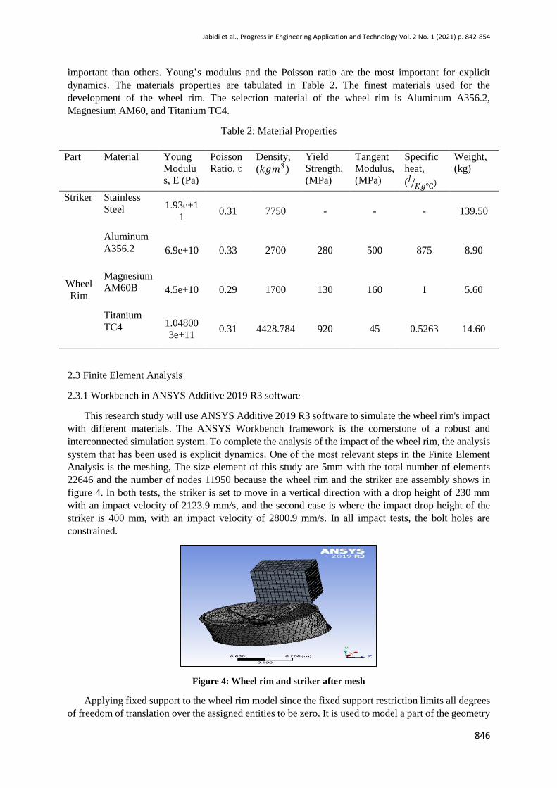
Table 2: Material Properties
Part Material Young
Modulu
s, E (Pa)
Poisson
Ratio, ʋ
Density,
(𝑘𝑔𝑚3)
Yield
Strength,
(MPa)
Tangent
Modulus,
(MPa)
Specific
heat,
(𝐽𝐾𝑔℃⁄ )
Weight,
(kg)
Striker Stainless
Steel 1.93e+1
1 0.31 7750 - - - 139.50
Wheel
Rim
Aluminum
A356.2 6.9e+10 0.33 2700 280 500 875 8.90
Magnesium
AM60B 4.5e+10 0.29 1700 130 160 1 5.60
Titanium
TC4 1.04800
3e+11 0.31 4428.784 920 45 0.5263 14.60
2.3 Finite Element Analysis
2.3.1 Workbench in ANSYS Additive 2019 R3 software
This research study will use ANSYS Additive 2019 R3 software to simulate the wheel rim's impact
with different materials. The ANSYS Workbench framework is the cornerstone of a robust and
interconnected simulation system. To complete the analysis of the impact of the wheel rim, the analysis
system that has been used is explicit dynamics. One of the most relevant steps in the Finite Element
Analysis is the meshing, The size element of this study are 5mm with the total number of elements
22646 and the number of nodes 11950 because the wheel rim and the striker are assembly shows in
figure 4. In both tests, the striker is set to move in a vertical direction with a drop height of 230 mm
with an impact velocity of 2123.9 mm/s, and the second case is where the impact drop height of the
striker is 400 mm, with an impact velocity of 2800.9 mm/s. In all impact tests, the bolt holes are
constrained.
Figure 4: Wheel rim and striker after mesh
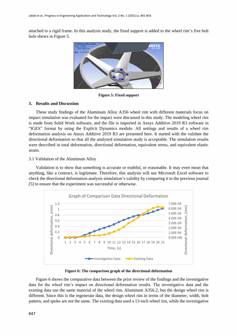
Applying fixed support to the wheel rim model since the fixed support restriction limits all degrees
of freedom of translation over the assigned entities to be zero. It is used to model a part of the geometry
Jabidi et al., Progress in Engineering Application and Technology Vol. 2 No. 1 (2021) p. 842-854
847
attached to a rigid frame. In this analysis study, the fixed support is added to the wheel rim’s five bolt
hole shows in Figure 5.
Figure 5: Fixed support
3. Results and Discussion
These study findings of the Aluminum Alloy A356 wheel rim with different materials focus on
impact simulation was evaluated for the impact were discussed in this study. The modeling wheel rim
is made from Solid Work software, and the file is imported in Ansys Additive 2019 R3 software in
“IGES” format by using the Explicit Dynamics module. All settings and results of a wheel rim
deformation analysis on Ansys Additive 2019 R3 are presented here. It started with the validate the
directional deformation so that all the analyzed simulation study is acceptable. The simulation results
were described in total deformation, directional deformation, equivalent stress, and equivalent elastic
strain.
3.1 Validation of the Aluminum Alloy
Validation is to show that something is accurate or truthful, or reasonable. It may even mean that
anything, like a contract, is legitimate. Therefore, this analysis will use Microsoft Excel software to
check the directional deformation analysis simulation’s validity by comparing it to the previous journal
[5] to ensure that the experiment was successful or otherwise.
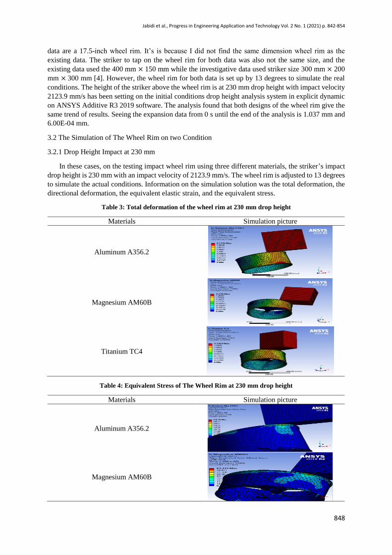
Figure 6: The comparison graph of the directional deformation
Figure 6 shows the comparative data between the prior review of the findings and the investigative
data for the wheel rim’s impact on directional deformation results. The investigative data and the
existing data use the same material of the wheel rim, Aluminum A356.2, but the design wheel rim is
different. Since this is the regenerate data, the design wheel rim in terms of the diameter, width, bolt
pattern, and spoke are not the same. The existing data used a 13-inch wheel rim, while the investigative
0.00E+00
1.00E-04
2.00E-04
3.00E-04
4.00E-04
5.00E-04
6.00E-04
7.00E-04
0
0.2
0.4
0.6
0.8
1
1.2
1 2 3 4 5 6 7 8 9 10 11 12 13 14 15 16 17 18 19 20 21
Dir
ecti
on
al d
efo
rmat
ion
, (m
m)
Dir
ecti
on
al d
efo
rmat
ion
, (m
m)
Time, (s)
Graph of Comparison Data Directional Deformation
Investigation Data Existing Data
Jabidi et al., Progress in Engineering Application and Technology Vol. 2 No. 1 (2021) p. 842-854
848
data are a 17.5-inch wheel rim. It’s is because I did not find the same dimension wheel rim as the
existing data. The striker to tap on the wheel rim for both data was also not the same size, and the
existing data used the 400 mm × 150 mm while the investigative data used striker size 300 mm × 200
mm × 300 mm [4]. However, the wheel rim for both data is set up by 13 degrees to simulate the real
conditions. The height of the striker above the wheel rim is at 230 mm drop height with impact velocity
2123.9 mm/s has been setting on the initial conditions drop height analysis system in explicit dynamic
on ANSYS Additive R3 2019 software. The analysis found that both designs of the wheel rim give the
same trend of results. Seeing the expansion data from 0 s until the end of the analysis is 1.037 mm and
6.00E-04 mm.
3.2 The Simulation of The Wheel Rim on two Condition
3.2.1 Drop Height Impact at 230 mm
In these cases, on the testing impact wheel rim using three different materials, the striker’s impact
drop height is 230 mm with an impact velocity of 2123.9 mm/s. The wheel rim is adjusted to 13 degrees
to simulate the actual conditions. Information on the simulation solution was the total deformation, the
directional deformation, the equivalent elastic strain, and the equivalent stress.
Table 3: Total deformation of the wheel rim at 230 mm drop height
Materials Simulation picture
Aluminum A356.2
Magnesium AM60B
Titanium TC4
Table 4: Equivalent Stress of The Wheel Rim at 230 mm drop height
Materials Simulation picture
Aluminum A356.2
Magnesium AM60B

Jabidi et al., Progress in Engineering Application and Technology Vol. 2 No. 1 (2021) p. 842-854
849
Titanium TC4
Table 5: Equivalent Elastic Strain of The Wheel Rim at 230 mm drop height
Materials Simulation picture
Aluminum A356.2
Magnesium AM60B
Titanium TC4
3.2.2 Drop Height Impact at 400 mm
For these cases, for simulation impact wheel rims using three different materials, the striker's impact
drop height is 400 mm with an impact velocity of 2800.9 mm/s. The wheel rim is calibrated to 13
degrees in order to simulate the real conditions. Details on the simulation approach were the total
deformation, the directional deformation, the equivalent elastic strain, and the equivalent stress.
Table 6: Total Deformation of The Wheel Rim at 400 mm drop height
Materials Simulation picture
Aluminum A356.2
Magnesium AM60B

Jabidi et al., Progress in Engineering Application and Technology Vol. 2 No. 1 (2021) p. 842-854
850
Titanium TC4
Table 7: Equivalent Stress of The Wheel Rim at 400 mm drop height
Materials Simulation picture
Aluminum A356.2
Magnesium AM60B
Titanium TC4
Table 8: Equivalent Elastic Strain of The Wheel Rim at 400 mm drop height
Materials Simulation picture
Aluminum A356.2
Magnesium AM60B
Titanium TC4

Jabidi et al., Progress in Engineering Application and Technology Vol. 2 No. 1 (2021) p. 842-854
851
3.3 Collective Data Simulation
Table 3: Obtained results
Materials
Drop
Height
Impact
(mm)
Total
Deformation
(mm)
Equivalent
Elastic
Strain
(mm/mm)
Equivalent
Stress
(MPa)
Factor
of
Safety
Weight
of the
wheel
rim,
(kg)
Aluminum
A356.2
230 2.1745 3.01 200.00 1.21 8.90
400 2.975 3.513 232.16 1.4
Magnesium
AM60B
230 2.228 2.322 97.437 1.33 5.60
400 3.05 2.8199 124.84 1.04
Titanium
TC4
230 2.142 5.278 496.81 1.85 14.60
400 2.866 5.7381 542.45 1.70
Figure 7: Comparison of The Total Deformation with different materials
Figure 7 compares the total deformation for material Aluminum A356.2, Magnesium AM60B, and
Titanium TC4. Overall, Magnesium AM60B is the tallest than the other materials, in condition 400 mm
drop height with 2.975 mm while in condition 230mm drop height the value is 2.1745 mm. So, proven
that the Magnesium AM60B can absorb more impact than the collision will slow down until it's fully
damaged. In total deformation, the maximum total deformation value will be absorbed by the highest
impact since deformation is the action or deformation or distortion mechanism.
Figure 8: Comparison of The Equivalent Elastic Strain with different materials
0
1
2
3
4
Aluminum A356.2 Magnesium AM60B Titanium TC4
Tota
l Def
orm
atio
n, (
mm
)
Materials
Comparison of Materials In Total Deformation
230mm 400mm
0
2
4
6
8
Aluminum A356.2 Magnesium AM60B Titanium TC4
Equ
ival
ent
Elas
tic
Stra
in,
(mm
/mm
)
Materials
Comparison of Materials in Equivalent Elastic Strain
230mm 400mm
Jabidi et al., Progress in Engineering Application and Technology Vol. 2 No. 1 (2021) p. 842-854
852
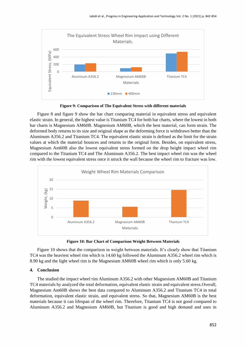
Figure 9: Comparison of The Equivalent Stress with different materials
Figure 8 and figure 9 show the bar chart comparing material in equivalent stress and equivalent
elastic strain. In general, the highest value is Titanium TC4 for both bar charts, where the lowest in both
bar charts is Magnesium AM60B. Magnesium AM60B, which the best material, can form strain. The
deformed body returns to its size and original shape as the deforming force is withdrawn better than the
Aluminum A356.2 and Titanium TC4. The equivalent elastic strain is defined as the limit for the strain
values at which the material bounces and returns to the original form. Besides, on equivalent stress,
Magnesium Am60B also the lowest equivalent stress formed on the drop height impact wheel rim
compared to the Titanium TC4 and The Aluminum A356.2. The best impact wheel rim was the wheel
rim with the lowest equivalent stress once it struck the wall because the wheel rim to fracture was low.
Figure 10: Bar Chart of Comparison Weight Between Materials
Figure 10 shows that the comparison in weight between materials. It’s clearly show that Titanium
TC4 was the heaviest wheel rim which is 14.60 kg followed the Aluminum A356.2 wheel rim which is
8.90 kg and the light wheel rim is the Magnesium AM60B wheel rim which is only 5.60 kg.
4. Conclusion
The studied the impact wheel rim Aluminum A356.2 with other Magnesium AM60B and Titanium
TC4 materials by analyzed the total deformation, equivalent elastic strain and equivalent stress.Overall,
Magnesium Am60B shows the best data compared to Aluminum A356.2 and Titanium TC4 in total
deformation, equivalent elastic strain, and equivalent stress. So that, Magnesium AM60B is the best
materials because it can lifespan of the wheel rim. Therefore, Titanium TC4 is not good compared to
Aluminum A356.2 and Magnesium AM60B, but Titanium is good and high demand and uses in
0
200
400
600
Aluminum A356.2 Magnesium AM60B Titanium TC4
Equ
ival
ent
Stre
ss,
(MP
a)
Materials
The Equivalent Stress Wheel Rim Impact using Different Materials.
230mm 400mm
0
5
10
15
20
Aluminum A356.2 Magnesium AM60B Titanium TC4
Wei
ght,
(kg
)
Materials
Weight Wheel Rim Materials Comparison

Jabidi et al., Progress in Engineering Application and Technology Vol. 2 No. 1 (2021) p. 842-854
853
aerospace. It shows that the best impact wheel rim was the wheel rim with the lowest equivalent stress
once it struck the wall because the wheel rim to fracture was low.
However, the Magnesium AM60B cost is twice expensive as Aluminum A356.2, but in the
manufacturing, producing Magnesium Am60B is better at casting parts with thinner walls and closer
tolerances than Aluminum A356.2 in the output wheel core. Many use Aluminum A356.2 as their wheel
rim due to the cost being cheaper than Magnesium AM60B.
Scope for Future Work: This study could make various proposals to enhance the future researcher
who wants to analyze wheel rim. Due to computer processing technology limitations, a very high mesh
setting could not reach the potential for future work. A higher mesh environment may be used for
research, and an explicit dynamic analysis can be used for potential work. This study could make
various proposals to enhance the future researcher who wants to analyze wheel rim.
Acknowledgement
The authors would like to thank the Faculty of Engineering Technology, Universiti Tun Hussein
Onn Malaysia for its support.
References
[1] Meshram, P. And Sinha, A., 2018. “Design & Optimization Of Alloy Wheel Rim Using
Ansys”. Smart Moves Journal Ijoscience, 4(6), P.5.
[2] Chilakala, M. And Garg, S., 2020. Three Dimensional Numerical Simulation Of Cracks In An
Automobile Wheel Rim. Materials Today: Proceedings, 26, Pp.2032-2039.
[3] Shinde, J., Kadam, S. And Pandit, S., 2017. International Research Journal Of Engineering And
Technology (IRJET). Review Paper On Design And Analysis Of Automotive Wheel Rim Using
Finite Element Analysis, 04(07).
[4] Zainuddin, H., Ali, M., Muhammad Said, N. And Zakaria, K., 2016. Correlation Between
Vertical Wheel Impact Energy With Lateral Wheel Impact Energy: A Finite Element Analysis
Approach. International Journal Of Automotive And Mechanical Engineering, 13(3), Pp.3574-
3583.
[5] Zapata, A., González-Estrada, O. And Pertuz, A., 2018. Damage Model For The Impact Test
Of An Automotive Aluminum Wheel. Journal Of Physics: Conference Series, 1126, P.012002.
[6] Priyanka, G., Murthy Raju, P. And Rajesh, S., 2020. Impact Analysis On Aluminum Alloy
Wheel Using ANSYS. International Journal For Research In Engineering Application &
Management (IJREAM), P.7.
[7] Meshram, P. And Sinha, A., 2018. “Design & Optimization Of Alloy Wheel Rim Using
Ansys”. Smart Moves Journal Ijoscience, 4(6), P.5.
[8] Zhang, J., Hao, L., Jiao, T., Que, L. and Wang, M., 2020. Mathematical morphology approach
to internal defect analysis of A356 aluminum alloy wheel hubs. AIMS Mathematics, 5(4),
pp.3256-3273.
[9] Frishfelds, V., Timuhins, A. And Bethers, U., 2018. Benefits Of Magnesium Wheels For
Consumer Cars. IOP Conference Series: Materials Science And Engineering, 355, P.012023.
[10] Jeevanantham V, Vadivelu P, Mahigandun P., 2017. “Material Based Structural Analysis Of A
Typical Landing Gear.” IJISET - International Journal Of Innovative Science, Engineering
&Amp; Technology, Vol. 4, No. 4, 4 Apr. 2017.

Jabidi et al., Progress in Engineering Application and Technology Vol. 2 No. 1 (2021) p. 842-854
854
[11] Professionale, I., 2019. ANSYS 2019 R3. [online] Parametric Design S.r.l. Available at:
<https://www.parametricdesign.it/new/blog-dettaglio.php?l=en&i_n=984> [Accessed 26
January 2021].
[12] Yang, Haibo, Hongjian Tan, Peng Hu, Xuewen Cheng, and Junlong Lu. (2018, September).
Impact test simulation and structural optimization of aluminum alloy A356. 2 wheel hub. In
Journal of Physics: Conference Series (Vol. 1074, No. 1, p. 012068). IOP Publishing.
[13] Asif, A., Jayakumar, V., Virinchy, C. And Shanmuganandam, K., 2018. Effect Of Mg, Sic And
Fly Ash Particulates In Aluminium Alloy For Automotive Wheel Rim Applications.
International Journal Of Vehicle Structures And Systems, 10(6).
[14] Jiang, X., Liu, H., Lyu, R., Fukushima, Y., Kawada, N., Zhang, Z. And Ju, D., 2019.
Optimization Of Magnesium Alloy Wheel Dynamic Impact Performance. Advances In
Materials Science And Engineering, 2019, Pp.1-12.
[15] Tocci, M., Pola, A., Montesano, L., Merlin, M., Luca Garagnani, G. And La Vecchia, G., 2017.
Tensile Behavior And Impact Toughness Of An Alsi3mgcr Alloy. Procedia Structural Integrity,
3, Pp.517-525.
[16] Chandan S N, Vinayaka N And Sandeep G M, 2016. Design, Analysis And Optimization Of
Race Car Chassis For Its Structural Performance. International Journal Of Engineering
Research And, V5(07).
[17] Ahmadein, M., Pustal, B., Wolff, N. And Bührig-Polaczek, A., 2017. Determination And
Verification Of The Gap Dependent Heat Transfer Coefficient During Permanent Mold Casting
Of A356 Aluminum Alloy. Materialwissenschaft Und Werkstofftechnik, 48(12), Pp.1249-
1256.
[18] Kumar, R., Amarnath, G. And Raj, K., 2019. Experimental Studies Of Optimization Of
Automotive Wheel Rim Using ANSYS. International Journal Of Trend In Scientific Research
And Development, Volume-3(Issue-3), Pp.311-316.
[19] REN, Z., 2018. Study On Wheel/Rail Impact Dynamics With Three Dimensional Wheel Flat
Model. Journal Of Mechanical Engineering, 54(15), P.78.
[20] Yang, L., Yang, H., Tan, H., Hu, P., Cheng, X. And Lu, J., 2018. Impact Test Simulation And
Structural Optimization Of Aluminum Alloy A356.2 Wheel Hub. Journal Of Physics:
Conference Series, 1074, P.012068.
Top Related