


Languages
Pages
Legal


Alma Mater Studiorum – Università di Bologna
DOTTORATO DI RICERCA IN
INGEGNERIA ELETTROTECNICA
_______________________
Ciclo XXVII
Settore Concorsuale di afferenza: 09/E2
Settore Scientifico disciplinare: ING-IND/32
ANALYSIS AND DESIGN OF HIGH
PERFORMANCE MULTIPHASE
ELECTRIC DRIVES FOR VEHICLE
AND AIRCRAFT APPLICATIONS
Presentata da: GIANCARLO RINI
Coordinatore Dottorato
Prof. Domenico Casadei
Relatore
Prof. Giovanni Serra
Esame finale anno 2015

TABLES OF CONTENTS
Preface .......................................................... 7
Chapter 1 Tools for automation electromagnetic finite element
analysis about rotating electrical machines ..................... 10
1.1 Introduction ............................................ 10
1.2 Finite Element Analysis with FEMM ....................... 11
1.2.1 Partial Differential Equations ....................... 11
1.2.2 Magnetostatic Problem ................................ 12
1.3 About ―Lua Motor‖ ....................................... 13
1.3.1 Aims of Lua Motor .................................... 13
1.3.2 Using the "Lua Motor" ................................ 15
1.3.3 Construction of Geometric Models ..................... 17
Chapter 2 Analysis of Synchronous Machine with External Rotor
for ―Emilia 3‖ Solar Car ....................................... 22
2.1 Summary of the PMSM design details ...................... 23
2.1.1 Cogging Torque ....................................... 24
2.1.2 No Load condition .................................... 25
2.1.3 Load condition ....................................... 27
2.2 Experimental result ..................................... 29
Chapter 3 Developments about More Electric Aircraft ............ 30
3.1 Introduction ............................................ 30
3.2 More Electric Aircraft (MEA) ............................ 32
3.3 Power generator ......................................... 36
3.3.1 Generating power at constant frequency ............... 37
3.3.2 Generating power at variable frequency ............... 38
3.4 More Electric Engine (MEE) .............................. 38
3.5 System Security ......................................... 41
3.5.1 Drive for flight control application ................. 42
3.5.2 Electromechanical Actuators (EMA) .................... 43
3.5.3 Electric-Hydraulic Actuator (EHA) .................... 44
3.6 Electric Fuel Pump ...................................... 46
3.7 On board Power Generation ............................... 46
3.8 Regeneration energy onto the electrical power bus ....... 47
3.8.1 Local energy dissipation ............................. 48
3.8.2 Centralized energy storage ........................... 48
3.8.3 Return energy to the source .......................... 49
3.9 Multi-Phase Drivers and Machine ......................... 50
Chapter 4 Design of a Multiphase Induction Machine for an Open
Rotor Aero-Engine Shaft Line Embedded Starter/Generator ........ 52
4.1 Abstract ................................................ 52
4.2 Introduction ............................................ 53
4.3 Open rotor Jet Engines .................................. 53
4.4 Fault tolerant multi-phase drives ....................... 54
4.5 Machine Design Criteria ................................. 56
4.6 Design Procedure ........................................ 56
4.7 Target design ad prototype .............................. 59
4.8 Equivalent Circuit Parameters Measurements .............. 63
4.8.1 No Load Tests ........................................ 63
4.8.2 Locked rotor tests ................................... 67
4.9 Load Test and Validation of the Simulations ............. 68
4.10 Prototype Performance Comparisons ....................... 70
4.11 Conclusions ............................................. 73
Chapter 5 Dynamic Stator Current Sharing in quadruple Three-
Phase Induction Motor Drive ..................................... 76
5.1 Abstract ................................................ 76
5.2 Introduction ............................................ 77
5.3 Quadruple three-phase induction machine ................. 78
5.3.1 Machine Model ........................................ 79
5.3.2 Three-Phase space vector ............................. 81
5.3.3 Multiple Space Vectors ............................... 81
5.4 Stator and current sharing control strategy ............. 82
5.5 Control Scheme .......................................... 83
5.5.1 Torque and Rotor Flux Control ........................ 84
5.5.2 Auxiliary Stator Current Control ..................... 84
5.5.3 Modulation Strategy of the Four Three-phase Inverters 86
5.6 Simulation Results ...................................... 86
5.7 Conclusion .............................................. 90
Chapter 6 A Modulation Strategy for Matrix Converter with
Extended Control Range and Reduced Switching Power Losses ....... 92
6.1 Abstract ................................................ 92
6.2 Introduction ............................................ 92

6.3 A Review of the Modulation Strategy for Matrix Converters 94
6.4 Extension of the operating range ........................ 97
6.5 Optimization of the Switching Losses ................... 98
6.5.1 Switching Losses ..................................... 99
6.6 Simulation Result ...................................... 102
6.7 Experimental Result .................................... 106
6.8 Conclusion ............................................. 108
Chapter 7 Modulation Strategy with Minimum Switching Losses for
Three-Phase AC-DC Matrix Converters ............................ 110
7.1 Abstract ............................................... 110
7.2 Introduction ........................................... 110
7.3 Modulation Strategy for AC/DC Matrix Converters ........ 112
7.3.1 Input Output Equations of the AC/DC Matrix Converters 112
7.3.2 Input-Output Equations in Terms of Space Vectors .... 113
7.3.3 Control Range of the output Voltage ................. 114
7.4 Improvement in the Switching Losses and Output Current
Ripple ....................................................... 116
7.4.1 General Expression of the Switching Losses .......... 116
7.4.2 Optimal Zero Sequence Component for the Reduction of the
Switching Losses ........................................... 117
7.4.3 Optimal Expression of the Switching Losses .......... 119
7.4.4 Numerical Simulations ............................... 119
7.5 Experimental Results ................................... 123
7.6 Conclusion ............................................. 123
Final Conclusion ............................................... 125
List of the main Used acronyms ................................. 127
References ..................................................... 128
Appendix A ..................................................... 137
Hardware ..................................................... 137
Driver Board ............................................... 137
Power Board ................................................ 147
List of paper of Giancarlo Rini .............................. 153

6

7
PREFACE
In the transport sector the ―more electric‖ solutions are
gaining attention in order to reduce energy and increase
efficiency and reliability and at the same time to reduce
emissions and maintenance costs. Many examples can be found: from
road transport, where hybrid electric vehicles are gaining
popularity, to the sea transport, where the electric drive
propulsion system is a very active and fast-growing research area.
In this general frame, aerospace applications have found that the
progressive electrification of on-board services is a way to
reduce or to remove the dependence on hydraulic, mechanical and
the bleed air/pneumatic systems.
The technological process in the transport sector has brought
significant improvements. Currently it is expected a continuation
of this growth, especially as regards the freight traffic. They
are, therefore, considerable pressures from aviation manufacturers
for the improvement of new aircraft in terms of safety, emissions
and noise. Growing interest to adopt new technologies on board the
aircraft, and it is widely agreed that the entire aviation system
should be profoundly rethought. In this sense, the concept of
greatest impact on the architecture of the aircraft is summed up
in the expression More Electric Aircraft (MEA), which indicates
the increasing adoption of electrical systems instead of
conventional hydraulic, pneumatic and mechanical systems.
For the future it is expected that the new generation of civil
aircraft require high electrical power to meet the growing demand
for electrical loads of the aircraft. And then next to the MEA
concept is born the More Electric Engine (MEE), in which one or
more electrical machines integrated into the engine aeronautical
performing functions of generation and start-up.
In order to use the MEA/MEE, the most important technology is
undoubtedly the power electronics. However, aerospace applications
present some challenging conditions for electronic systems; There
are still a number of studies to be carried out to make
improvements in terms of weight, cost and reliability of the
systems. A significant improvement in machines and electric drives
for applications MEA can certainly come from the use of multi-
phase drives.
The field of study of multiphase machines is a relatively new
field and in great development, but it is already possible to say
that these machines are able to provide better performance than
three phase. This technology, is characterized by a number of
issues that make it attractive in comparison to conventional
systems.

8
Multiphase systems, allow to redistribute power at a higher
number of phases, thus making possible the construction of
electronic converters which otherwise would be very difficult to
achieve due to the limits of present power electronics. Multiphase
drive have an intrinsic reliability thanks to the fact that a
failure on one phase, caused by the possible failure of a
component of the converter, can be solved by reducing performance
of the machine.
The control of the magnetic spatial harmonics in the air-gap
with order higher than one allows to reduce torque noise and to
obtain high torque density motor.
The aerospace specific requirements in terms of lightness,
reliability, cost, fault tolerance, fault propagation, harsh
ambient conditions and standard compliance have challenged the
body of knowledge and the creativity of the electrical designers
both in the industry and academic environments. In the past years
many EU projects and initiatives have been developed to explore
the MEA/MEE concepts. The research results have already brought to
the development of many electric devices that are now installed in
large civil aircraft by Airbus and Boeing, which are the beginning
of the adoption of the MEA concept.
During the Ph.D. course several themes have been developed that,
while obtaining the recent and growing interest of scientific
community, have much space for the development of research
activity and for industrial applications.

9

10
Chapter 1
TOOLS FOR AUTOMATION ELECTROMAGNETIC
FINITE ELEMENT ANALYSIS ABOUT
ROTATING ELECTRICAL MACHINES
1.1 INTRODUCTION
The initial purpose of these first activity was to develop some
tools for automating electromagnetic finite element analysis of
rotating electrical machines.
The analysis of a generic electromagnetic structure consists in
the study of the distribution of the electromagnetic fields that
develop inside the structure studied and particularly so in the
region of the air gap.
Usually one of the first steps to be taken in the design of
rotating electrical machine, is the geometric design in a CAD
(Computer-Aided Design). In fact, consolidated knowledge of CAD
applications have to dedicate a lot of time to both the design of
the lamination geometric (which could also show complex geometry)
that the setting of the relevant physical parameters responsible
for simulation development environments prone to simulation (FEMM
by David Maker, Flu By Cedrat, MagNet By Infolytica, etc.).
These operations are repetitive but essential and in this
context we find the development of a software package that
automates the operations, giving easy access to the simulations
and a safe time savings.
In particular the work done personally has been the development
of a software that integrates directly with FEMM (open source
software for analysing electromagnetic finite element) and
automatically generate some geometries of laminations relative to
rotating electrical machines.
In order to achieve the result shown in this discussion,
reference was made to the knowledge assodate thanks to the courses
of machines and electrical drives, performing a job analysis of
the problems closely related to the design of such machines. In
this work has been supported a study of the tools necessary for
the development of the software and in particular the techniques
of parametric design.

11
The results were the basis of the development of "Lua Motor" as
they have allowed to associate with specific aspects of the design
of electric machines and computer tools that enable the creation
of parametric models.
The global solution obtained is therefore the result of a survey
aimed at obtaining tools characterized by ease of use and
reliability of the results, these features allowed thanks to the
knowledge of both aspects of the design, electromagnetic and
computer science. These qualities make the software developed a
useful and important in the design phase of machines and
electrical drives.
1.2 FINITE ELEMENT ANALYSIS WITH FEMM
FEMM (Finite Element Method Magnetics) is a suite of programs for
solving low frequency electromagnetic problems on two-dimensional
planar and axisymmetric domains. The program currently addresses
linear/nonlinear magnetostatic problems, linear/nonlinear time
harmonic magnetic problems, linear electrostatic problems, and
steady-state heat flow problems.
FEMM is divided into three part:
1. Pre-processor
2. Solver
3. Post-Processing
The Pre-Processor sets the problem both from a geometrical point
of view, and to a physical point of view, defining the materials
and the boundary conditions of the system.
The phase Solver consists in analysis to the computer calculations
necessary to the solution of the problem.
The phase of Post-Processor allows, finally, an accurate analysis
of the results obtained.
1.2.1 PARTIAL DIFFERENTIAL EQUATIONS
FEMM addresses some limiting cases of Maxwell’s equations. The
magnetics problems addressed are those that can be considered as
―low frequency problems,‖ in which displacement currents can be
ignored. Displacement currents are typically relevant to magnetics
problems only at radio frequencies.

12
1.2.2 MAGNETOSTATIC PROBLEM
Magnetostatic problems are problems in wich the fields are
time-invariant. In this case, the field intensity (H) and Flux
Density (B) must obey:
(1-1)
(1-2)
subject to a constitutive relationship between B and H for each
material:
(1-3)
If the material is nonlinear (e.g. saturating Iron or AlNiCo
magnets), the permeability, µ is actually a function of B:
(1-4)
FEMM goes about finding a field that satisfies (1-1) - (1-3) via a
magnetic vector potential approach. Flux Density is written in
terms of the vector potential, A, as:
(1-5)
Now, this definition of B always satisfies (1-2). Then, (1-1) can
be rewritten as:
(
) (1-6)
For a linear isotropic material (and assuming the Coulomb gauge
), eq. (1-6) reduces to:
(1-7)
FEMM retains the form of (1-6), so that magnetostatic problems
with a nonlinear B-H relationship can be solved.
In the general 3-D case, A is a vector with three components.
However, in the 2-D planar and axisymmetric cases, two of these
three components are zero, leaving just the component in the ―Out
of the page‖ direction.

13
The advantage of using the vector potential formulation is that
all the condition to be satisfied have been combined into a single
equation. If A is found, B and H can then be deduced by
differentiating A. The form (1-6), an elliptic partial
differential equation, arises in the study of many different types
of engineering phenomenon.
1.3 ABOUT “LUA MOTOR”
The program created for the satisfaction of the features set out
above, "Lua Motor", was developed through the Visual Basic .NET
language. Visual Basic .NET (VB.NET) is a multi-paradigm, high
level programming language, Implemented on the .NET Framework.
The software "Lua Motor" allows you to create a generic plate of a
motor directly in FEMM. Along with this software have created a
set of libraries ready to interface with FEMM using another
language, Lua (Version 4.0). So it's easy to understand how it is
possible to create a design abandoning the traditional method
(mouse and keyboard) in favour of a programming approach.
The possibilities of using these two languages cover a wide range
of applications but in this case only a small part of them have
been exploited. This discussion will be given particular attention
given to the problems concerning geometric constructions,
especially in view finite element study.
1.3.1 AIMS OF LUA MOTOR
Verified the usefulness of the software capable of generating the
drawing, it is important to establish the characteristics that it
must possess.
First, the software needs to be effective and therefore must
perform a correct drawing corresponding to reality and compatible
to the needs of the remaining simulation environment.
Second, the software must be easy to use (user-friendly), that is
capable of being able to build the chart pattern starting with
little information that must be able to be communicated to the
application in a simple and intuitive.

14
The ease of use also involves the efficient management of the
errors that may occur, due, for example, the inconsistencies of
the data provided by the user.
In response to these needs the software has a series of solutions,
listed below, which have led to the final result shown in this
discussion:
To ensure the efficiency of the software and a correct
execution of the design has been conducted a study on the
geometric construction of the different types of laminations
which the application is able to generate. Have been
identified for each type of design of the basic parameters
(and not redundant so as to minimize the number) on which you
can go to reconstruct the whole geometry of the sheet. This
was achieved by identifying the Cartesian coordinates of each
point necessary for the construction of lines and arcs of a
circle belonging to the design and making use of
trigonometric and algebraic tools. This will ensure that the
fundamental equations obtained, the design generated based on
the starting parameters provided by the user always
corresponds to what it really means to represent.
Compatibility with both development environments (Lua Motor
and FEMM) has necessitated the creation of geometries
specifically designed for the simulation program and the
possibility to store some data, related to the design
generated in text files with a specific structure.
The first aspect of ease of use, that is the opportunity to
create the drawing starting with little information, is
closely linked with the first of the points outlined here and
also justifies the reason for the minimization of the basic
parameters. The user, in fact, to be able to realize the
design, will only have to indicate some specific measures for
the sheet of interest.
The simplicity of communication with the program suggested
the importance of the development of a graphic interface able
to guarantee a simple procedure for the input of data, as
well as the possibility of using text files, as well as an
interface for FEMM , also as a data base from which to
quickly recall previously created projects.
Importantly, it has come to the development of such solutions
gradually and in response to the needs that, carrying on the work,
were to occur.
15
At first it has been an increased attention to the development of
that part of the software that allow to generate the drawing
(Library Lua) and immediately with it has been taken into
consideration the possibility of creating interface files. At this
stage of development are followed those concerning the graphical
interface.
1.3.2 USING THE "LUA MOTOR"
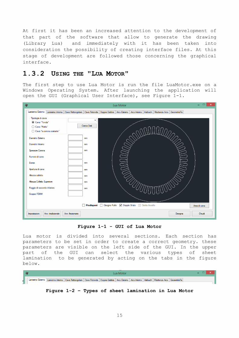
The first step to use Lua Motor is run the file LuaMotor.exe on a
Windows Operating System. After launching the application will
open the GUI (Graphical User Interface), see Figure 1-1.
Figure 1-1 - GUI of Lua Motor
Lua motor is divided into several sections. Each section has
parameters to be set in order to create a correct geometry. these
parameters are visible on the left side of the GUI. In the upper
part of the GUI can select the various types of sheet
lamination to be generated by acting on the tabs in the figure
below.
Figure 1-2 – Types of sheet lamination in Lua Motor
16
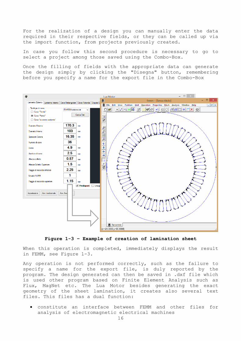
For the realization of a design you can manually enter the data
required in their respective fields, or they can be called up via
the import function, from projects previously created.
In case you follow this second procedure is necessary to go to
select a project among those saved using the Combo-Box.
Once the filling of fields with the appropriate data can generate
the design simply by clicking the "Disegna" button, remembering
before you specify a name for the export file in the Combo-Box
Figure 1-3 – Example of creation of lamination sheet
When this operation is completed, immediately displays the result
in FEMM, see Figure 1-3.
Any operation is not performed correctly, such as the failure to
specify a name for the export file, is duly reported by the
program. The design generated can then be saved in .dxf file which
is used other program based on Finite Element Analysis such as
Flux, MagNet etc. The Lua Motor besides generating the exact
geometry of the sheet lamination, it creates also several text
files. This files has a dual function:
constitute an interface between FEMM and other files for
analysis of electromagnetic electrical machines

17
as a database of projects
These .txt files are automatically saved in folders created in
order to organize these files in a correct mode.
1.3.3 CONSTRUCTION OF GEOMETRIC MODELS
The current version of Lua Motor is able to generate different
types of sheet in order to study:
Asynchronous machines
o Inner rotor with single cage or double cage
o External rotor with single cage
Synchronous machines
o Inner rotor
o External rotor
o Hallbach rotor
o Inner reluctance rotor (SynRM)
As can be seen the software is able to cover a large number of
cases of different types of electrical machines.
To analyse an asynchronous electrical machine it is necessary to
have all geometric details about sheet lamination and the
characteristics of materials used.
Figure 1-4 – Example of induction machine (4 poles)
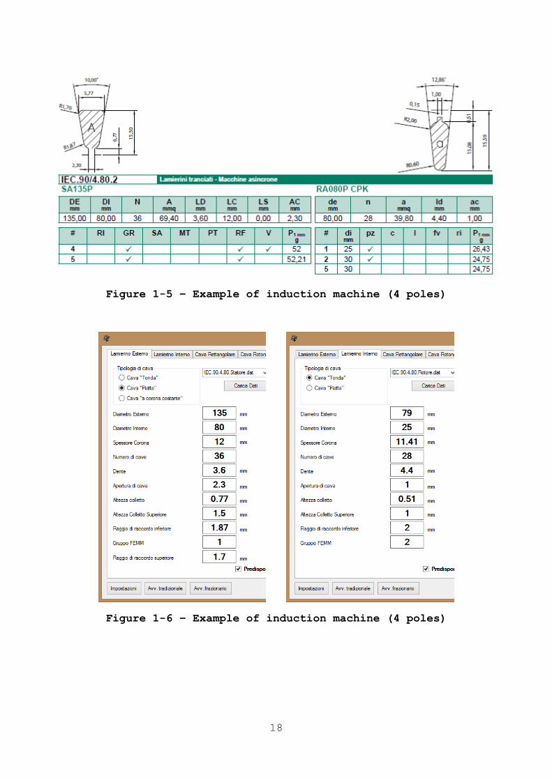
18
Figure 1-5 – Example of induction machine (4 poles)
Figure 1-6 – Example of induction machine (4 poles)
19
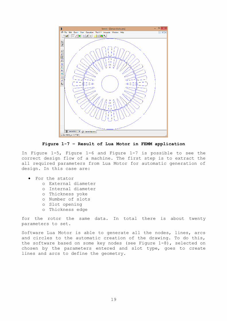
Figure 1-7 – Result of Lua Motor in FEMM application
In Figure 1-5, Figure 1-6 and Figure 1-7 is possible to see the
correct design flow of a machine. The first step is to extract the
all required parameters from Lua Motor for automatic generation of
design. In this case are:
For the stator
o External diameter
o Internal diameter
o Thickness yoke
o Number of slots
o Slot opening
o Thickness edge
for the rotor the same data. In total there is about twenty
parameters to set.
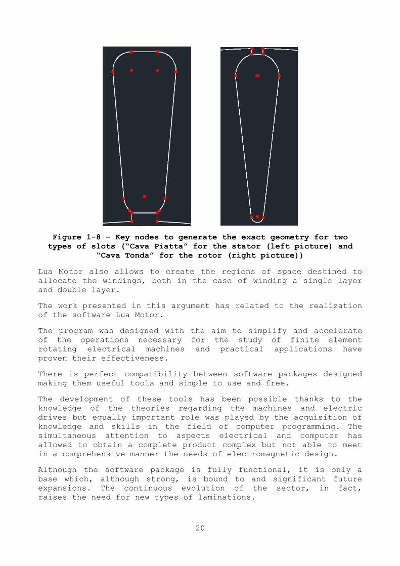
Software Lua Motor is able to generate all the nodes, lines, arcs
and circles to the automatic creation of the drawing. To do this,
the software based on some key nodes (see Figure 1-8), selected on
chosen by the parameters entered and slot type, goes to create
lines and arcs to define the geometry.
20
Figure 1-8 – Key nodes to generate the exact geometry for two
types of slots (“Cava Piatta” for the stator (left picture) and
“Cava Tonda” for the rotor (right picture))
Lua Motor also allows to create the regions of space destined to
allocate the windings, both in the case of winding a single layer
and double layer.
The work presented in this argument has related to the realization
of the software Lua Motor.
The program was designed with the aim to simplify and accelerate
of the operations necessary for the study of finite element
rotating electrical machines and practical applications have
proven their effectiveness.
There is perfect compatibility between software packages designed
making them useful tools and simple to use and free.
The development of these tools has been possible thanks to the
knowledge of the theories regarding the machines and electric
drives but equally important role was played by the acquisition of
knowledge and skills in the field of computer programming. The
simultaneous attention to aspects electrical and computer has
allowed to obtain a complete product complex but not able to meet
in a comprehensive manner the needs of electromagnetic design.
Although the software package is fully functional, it is only a
base which, although strong, is bound to and significant future
expansions. The continuous evolution of the sector, in fact,
raises the need for new types of laminations.

21
Just in anticipation of a future development I conceived the Lua
Motor as a modular software, so as to make it easily expandable
with the addition of new models without changing anything of what
already exists.
22
Chapter 2
ANALYSIS OF SYNCHRONOUS MACHINE WITH
EXTERNAL ROTOR FOR
“EMILIA 3” SOLAR CAR
A permanent magnet synchronous motors (PMSM) are widely used in
automotive applications and in industrial sector of medium and low
power application.
A synchronous electric motor is an AC motor in which, at steady
state, the rotation of the shaft is synchronized with the
frequency of the supply current; the rotation period is exactly
equal to an integral number of AC cycles. Synchronous motors
contain multiphase AC electromagnets on the stator of the motor
that create a magnetic field which rotates in time with the
oscillations of the line current. The rotor with permanent magnets
or electromagnets turns in step with the stator field at the same
rate and as a result, provides the second synchronized rotating
magnet field of any AC motor.
The brushless motor is an electric motor that in contrast to a
DC motor, has no need of sliding electrical contacts on the motor
shaft to work (hence the name "brushless"). The commutation of the
current flowing in the windings, in fact, is not made by
mechanically, but through electronic devices, with the consequence
of a lower mechanical strength, eliminating the possibility of
forming sparks, with increasing speed of rotation. With this type
of engines is significantly reduced the need for periodic
maintenance.
From an energy point of view, the brushless motors dissipate
heat better than an AC motor. The absence of copper on the rotor
and the presence of the windings on the stator allows to realize
machines without cooling fins. This is because the Joule losses
are only due to the stator windings.
These characteristics make them suitable for use in the aircraft
industry, automotive, in marine and increasingly popular hybrid
vehicles or electric vehicles.

23
In this chapter, I will describe the design of a brushless
machine. The engine has been designed, manufactured and tested.
The engine is directly mounted in a wheel, through a direct
coupling (direct drive). The synchronous machine will be part of
the one vehicle powertrain salt Italian who has successfully
participated in the World Solar Challenge 2013 (WSC2013) and the
Abu Dhabi Solar Challenge 2015 (ADSC2015). The vehicle has
completed over 4000km road proving in fact the correct design of
the electric motor.
2.1 SUMMARY OF THE PMSM DESIGN DETAILS
The Permanent Magnets Synchronous machine (PMSM) consists of
20 magnets and 18 slots. The PM Material adopted is NdFeB having a
coercitivity of and relative permeability .
The 18 slot – 20 pole structure with non-overlapping
concentrate winding was adopted. The electrical shift between coil sides results in magnetically de-coupled windings. Triplen
harmonic are naturally eliminated in the single phase EMF. The
main dimension and parameters are reported in Table 2-1.
Figure 2-1 – Finite Element Model: solution mesh
In Figure 2-1 it is possible to see the finite element model
used for the analysis. Circumferential magnet segmentation is
considered as a standard technique to reduce the magnet eddy
24
current losses, but in this case it isn’t necessary to divide the
magnetics because this motor cannot be used at high speed ( ).
The main features of the used materials are listed below:
Magnets => Material: NdFeB, ,
Stator/rotor core => Laminated non-oriented silicon steel
Copper => Resistivity
Torque (S1) 14 [Nm]
Max Torque 45 [Nm]
Rated Voltage 105 [V]
Type of connection Star connection
Number of poles 20
Rated speed 805 [rpm]
Number of slots 18
Outer stator diameter 230 [mm]
Inner stator diameter 152 [mm]
Air-gap thickness 1.5 [mm]
Magnets thickness 4 [mm]
Table 2-1 - Motor paramters
The adopted mesh used for the FE Analysis is presented in
Figure 2-1. The refinement of the mesh in the main air gap is
necessary to achieve a reasonable accuracy of the results. A three
phase winding configuration has been considered (star connection).
Two-dimensional time stepping analysis is considered.
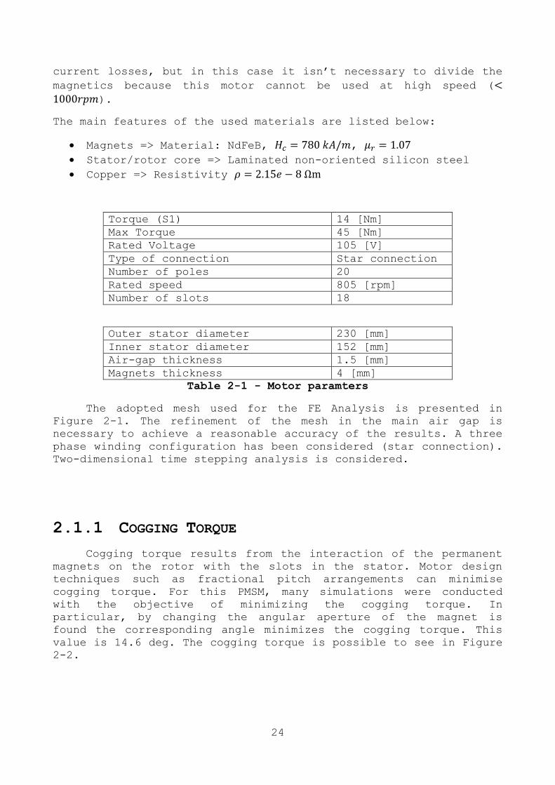
2.1.1 COGGING TORQUE
Cogging torque results from the interaction of the permanent
magnets on the rotor with the slots in the stator. Motor design
techniques such as fractional pitch arrangements can minimise
cogging torque. For this PMSM, many simulations were conducted
with the objective of minimizing the cogging torque. In
particular, by changing the angular aperture of the magnet is
found the corresponding angle minimizes the cogging torque. This
value is 14.6 deg. The cogging torque is possible to see in Figure
2-2.
25
Figure 2-2 - Cogging Torque versus mechanical angle
2.1.2 NO LOAD CONDITION
The no load condition is analysed to evaluate the no load EMF,
the relationship of the voltage with respect the speed ( ) an the
cogging torque featured by the machine. The Fourier Series
transformations has been applied to the calculated no load EMF
waveforms and the fundamental Harmonic has been considered. Linear
dependency of the no load voltages with respect the mechanical
speed is expected: the coefficient is calculated according to
(2-1)
(2-1)
where 805 rpm is the mechanical speed in root per minute. The
harmonic content of the no load EMF result limited at the
fundamental and some other harmonic, in particular the 5th and the
7th harmonic whereas no 3
rd harmonic is present as expected.
-0.04
-0.03
-0.02
-0.01
0
0.01
0.02
0.03
0.04
28 28.5 29 29.5 30 30.5
Co
ggin
g [N
m]
Mechanical angle [deg]
Cogging Torque

26
Figure 2-3 - No load EMF @ 805rpm
Figure 2-3 show the back electromotive force (BEMF) for
805rpm. Considering that the no load voltage is calculated
according with the Faraday-Lenz Law, the maximum of the no load
flux linkage for the phase A can be seen in Figure 2-4.
Figure 2-4 - Flux Linkage versus electric angle
-60
-40
-20
0
20
40
60
25 30 35 40 45 50 55 60 65 70
Eo [
V]
Ph
ase
A
electric angle [°el]
No load EMF @ 805rpm
-0.08
-0.06
-0.04
-0.02
0
0.02
0.04
0.06
0.08
0 50 100 150 200 250 300 350 400
Flu
x Li
nka
ge w
ith
Ph
ase
A [
Wb
]
electric angle [°el]

27
2.1.3 LOAD CONDITION
Loaded conditions are investigated with the aim to evaluate
ratio of the torque with respect the load current, iron and ohmic
stator winding losses. Transient 2D simulation are considered for
this analysis.
The magnetic axis related with one of the phases is aligned
with the magnetic axes of the rotor magnets to provide only a no
load positive d-axis component, coherent with the no load EMF
shown in Figure 2-3. A current-fed symmetric 3 phase supply in-
phase with the back-EMF is considered (i.e. q-axis current).
Maxwell Stress Tensor is the adopted technique to estimate the
instantaneous torque featured by the machine; the continuous
torque is calculated as the average over an electrical period of
the instantaneous result. The output torque is independent of the
speed of the machine.
Figure 2-5 - Torque waveforms @ I=10.6Arms
The torque waveform for one condition is evaluated and
illustrated in Figure 2-5. It is possible to see a small torque
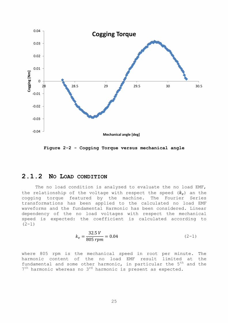
ripple, about 0.2Nm. Figure 2-6 present the flux density
distribution obtained with the 2D Model in FEMM.
13
13.2
13.4
13.6
13.8
14
14.2
14.4
14.6
14.8
15
20 25 30 35 40 45 50 55 60 65 70
Torq
ue
[N
m]
mechanical angle [deg]
Rated Torque @ 10.6 Arms
28
Figure 2-6 - |B| shaded plot for load condition simulation @
I=10.6Arms
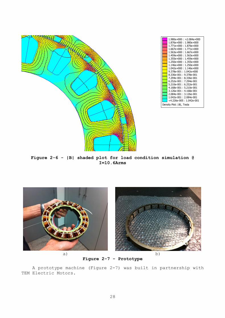
a) b)
Figure 2-7 - Prototype
A prototype machine (Figure 2-7) was built in partnership with
TEM Electric Motors.
Density Plot: |B|, Tesla
1.980e+000 : >2.084e+000
1.876e+000 : 1.980e+000
1.771e+000 : 1.876e+000
1.667e+000 : 1.771e+000
1.563e+000 : 1.667e+000
1.459e+000 : 1.563e+000
1.355e+000 : 1.459e+000
1.250e+000 : 1.355e+000
1.146e+000 : 1.250e+000
1.042e+000 : 1.146e+000
9.378e-001 : 1.042e+000
8.336e-001 : 9.378e-001
7.294e-001 : 8.336e-001
6.252e-001 : 7.294e-001
5.210e-001 : 6.252e-001
4.168e-001 : 5.210e-001
3.126e-001 : 4.168e-001
2.084e-001 : 3.126e-001
1.042e-001 : 2.084e-001
<4.226e-005 : 1.042e-001
29
2.2 EXPERIMENTAL RESULT
A short summary of the experimental tests carried out on the PMSM
with external rotor are observable in the following table.
Data Torque Speed Mot.
Power
Function Vdc Idc Pdc VLL Imot Rend.
motor
Nm rpm W Vrms Arms W
27/05/2013 15.3 704 1128 Motor 104.8 11.6 1218 37.31 11.5 0.972
27/05/2013 24.4 418 1068 Motor 104.7 12.3 1283 25.54 19.9 0.875
Table 2-2 – Experimental Result
We can observe that the efficiency (0.97) of the motor is very
high in its rated condition.
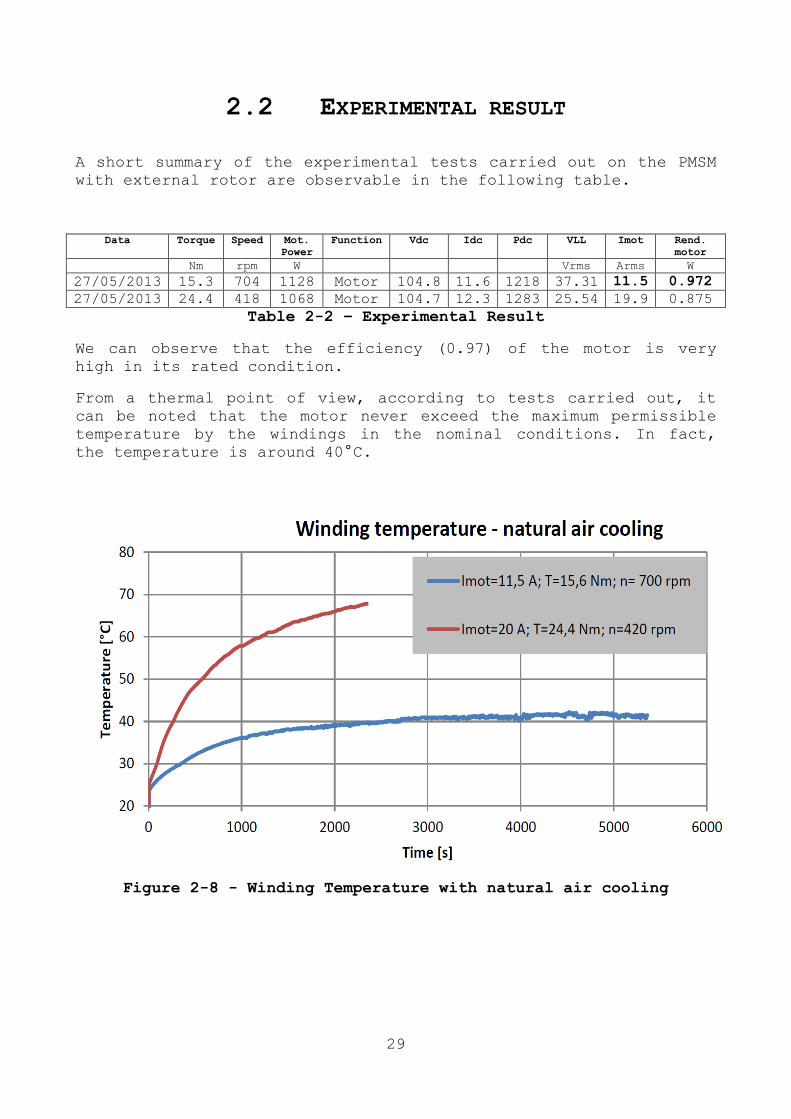
From a thermal point of view, according to tests carried out, it
can be noted that the motor never exceed the maximum permissible
temperature by the windings in the nominal conditions. In fact,
the temperature is around 40°C.
Figure 2-8 - Winding Temperature with natural air cooling

30
Chapter 3
DEVELOPMENTS ABOUT MORE ELECTRIC
AIRCRAFT
3.1 INTRODUCTION
Since 1960, the air traffic, both passenger and freight, has
increased and is expected until 2017, a steady increase in average
of 5% and 7% respectively [1]. As a result of this growth affects
a highly competitive market for all participants in the sector:
from the producer of the smallest components of an aircraft, to
travellers who expect continued improvements of features and
services offered accompanied by continuous reductions in costs and
environmental impact. With regard to the latter aspect, we can say
that the carbon dioxide emissions from aviation account for 2% of
global emissions. The aircraft engines, in fact, produce carbon
dioxide (CO2), nitrogen oxide (NOx), hydrocarbons (HC), carbon
monoxide (CO), the effects of which include:
- Climate change at high altitude;
- Air quality at low altitude.
Although the technological advances in the field have improved the
efficiency of aircraft and reduced transport costs, there are
still a lot of pressure on manufacturers to improve the
performance of future vehicles in terms of safety and air
pollution. In order to meet these expectations, the entire
aviation industry is planning to radically re-evaluate the whole
system aircraft. It is in fact necessary to revisit the whole
architecture of an aircraft, with the introduction of new
technologies for the performance of key functions on the aircraft.
Nowadays conventional civil aircraft are characterized by four
different secondary power distribution systems: mechanical,
hydraulic, pneumatic and electrical systems. This implies a
complex power distribution network on board and, given the
structure of the means of transport, the need for adequate
redundancy of each of them. Since the 80s, the US Air Force and
NASA have found a solution for the progressive reduction, or even
elimination, of such centralized power systems on board. To
improve the reliability of the system, maintenance, operating

31
costs and the weight of the aircraft have been proposed new
electric technologies that have recently made a major change in
the design. In this sense, the concept of greatest impact on the
architecture of the aircraft is concentrated in the expression
More Electric Aircraft (MEA), which indicates the growing adoption
of electric systems to replace conventional hydraulic, pneumatic
and mechanical systems. As a result, the electrical system of the
aircraft will be radically changed, so that's next to the MEA
concept, has strengthened the concept More Electric Engines (MEE),
where the electrical machines are integrated into the main turbine
to generate electricity, start the engine and ensure safety in the
event of failure during the flight.
In recent years, many projects have been developed to explore the
concepts MEA / MEE for both military and civil applications,
trying to achieve what will be the concept of the All Electrical
Aircraft (EEA).
In 2000, he launched the project Magnetostrictive Equipment and
Systems for More Electric Aircraft (MESA), which aims to reduce
power consumption and weight of onboard systems through the
development of magnetostrictive actuators and motors.
In 2002 it was the turn of the Power Optimized Aircraft (POA)
aimed at finding alternative equipment to reduce weight, fuel
consumption and maintenance costs of the aircraft.
In 2004, the project Magnetoelastic Energy Systems for Even More
Electric Aircraft (MESEMA) has been dedicated to the development,
production and testing of innovative transducer systems based on
active materials aiming for a drive with high torque density,
reduced vibration and noise generation of electricity and
structural integrity monitoring.
In 2006, the project More Open Electrical Technologies (MOET),
aimed to establish a new industry standard for the design of
commercial aircraft, in conjunction with the reduction of
emissions and improvement of operational capacity, as an evolution
of the concept of "fly-by-wire" to that of "power-by-wire".
All of these projects, which are now the ultimate expression of
MEA concept, have contributed to the development of many
electrical devices that are currently in use on modern vehicles.
For example, the electrification of the actuators of the flight
surfaces, Airbus A380 leads to less consumption, while reducing
costs, or the electrification of the cabin pressurization and air
conditioning, adopted by the Boeing 787, saves energy of 3-7%.
The most important technology that allows to use the MEA concept,
without a doubt, is the power electronics associated with
electrical machines and electric actuators. However, aeronautical
applications have some demanding conditions and there are still a
number of areas of use in which they must be made of the

32
improvements in terms of weight, cost and reliability of the
systems.
3.2 MORE ELECTRIC AIRCRAFT (MEA)
For a typical medium-sized aircraft, the only sources from which
to draw power, the engines are gas turbines, as shown in Figure
3-1. These turbines, as well as providing mainly the reliability
necessary for flight, they also provide food for all other loads
on the plane.
Figure 3-1 - Energy distribution in a conventional aircraft
In a conventional civil aircraft there are four types of renewable
energy derived from motor: electric, pneumatic, hydraulic and
mechanical.
The electrical system is used for power loads and for avionics
systems, lighting equipment and in-flight entertainment.
The pneumatic system, powered by the extraction of air from the
engine, shall govern the environmental control system
(pressurization and air conditioning) and wing protection against
the ice.
That mechanical, operated by a system of transmissions by the
engine, is used for pumping fuel and oil.
Finally, the hydraulic system is used for all the actuation
systems of the aircraft.
The assumption on which the MEA concept is based on, is that only
one single power source is available from the main motor. For this
purpose, the choice falls on a single electrical system, as it has
a series of advantages in terms of flexibility and range of
applications. A possible system designed for the MEA is shown in
Fig. 1.2, where all loads are powered by the on-board electrical
system.
33
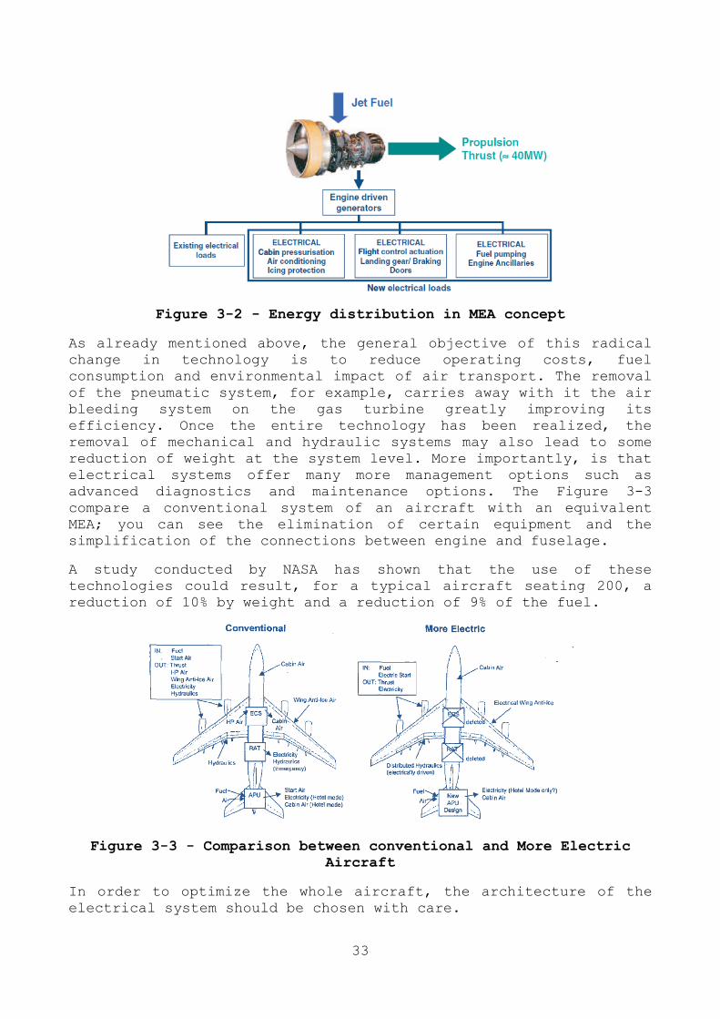
Figure 3-2 - Energy distribution in MEA concept
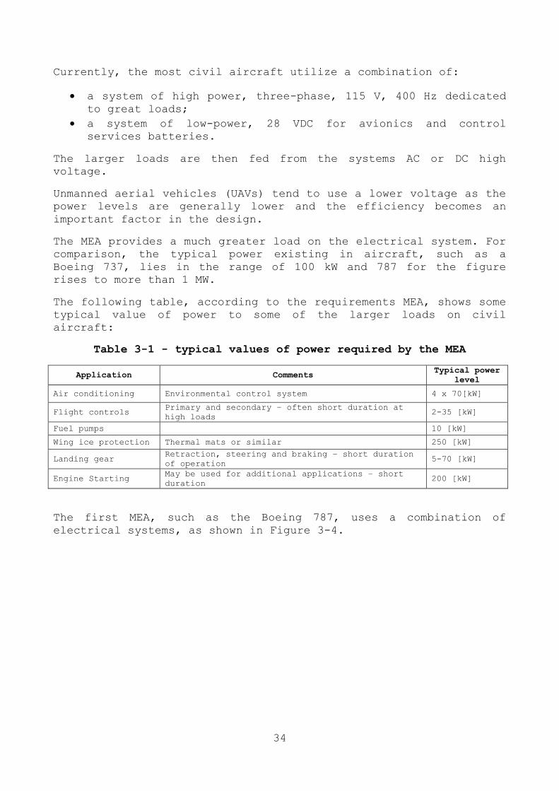
As already mentioned above, the general objective of this radical
change in technology is to reduce operating costs, fuel
consumption and environmental impact of air transport. The removal
of the pneumatic system, for example, carries away with it the air
bleeding system on the gas turbine greatly improving its
efficiency. Once the entire technology has been realized, the
removal of mechanical and hydraulic systems may also lead to some
reduction of weight at the system level. More importantly, is that
electrical systems offer many more management options such as
advanced diagnostics and maintenance options. The Figure 3-3
compare a conventional system of an aircraft with an equivalent
MEA; you can see the elimination of certain equipment and the
simplification of the connections between engine and fuselage.
A study conducted by NASA has shown that the use of these
technologies could result, for a typical aircraft seating 200, a
reduction of 10% by weight and a reduction of 9% of the fuel.
Figure 3-3 - Comparison between conventional and More Electric
Aircraft
In order to optimize the whole aircraft, the architecture of the
electrical system should be chosen with care.
34
Currently, the most civil aircraft utilize a combination of:
a system of high power, three-phase, 115 V, 400 Hz dedicated
to great loads;
a system of low-power, 28 VDC for avionics and control
services batteries.
The larger loads are then fed from the systems AC or DC high
voltage.
Unmanned aerial vehicles (UAVs) tend to use a lower voltage as the
power levels are generally lower and the efficiency becomes an
important factor in the design.
The MEA provides a much greater load on the electrical system. For
comparison, the typical power existing in aircraft, such as a
Boeing 737, lies in the range of 100 kW and 787 for the figure
rises to more than 1 MW.
The following table, according to the requirements MEA, shows some
typical value of power to some of the larger loads on civil
aircraft:
Table 3-1 - typical values of power required by the MEA
Application Comments Typical power
level
Air conditioning Environmental control system 4 x 70[kW]
Flight controls Primary and secondary – often short duration at
high loads 2-35 [kW]
Fuel pumps 10 [kW]
Wing ice protection Thermal mats or similar 250 [kW]
Landing gear Retraction, steering and braking – short duration
of operation 5-70 [kW]
Engine Starting May be used for additional applications – short
duration 200 [kW]
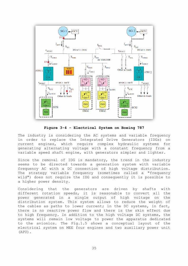
The first MEA, such as the Boeing 787, uses a combination of
electrical systems, as shown in Figure 3-4.
35
Figure 3-4 - Electrical System on Boeing 787
The industry is considering the AC systems and variable frequency
in order to replace the Integrated Drive Generators (IDGs) on
current engines, which require complex hydraulic systems for
generating alternating voltage with a constant frequency from a
variable speed shaft engine, with generators simpler and lighter.
Since the removal of IDG is mandatory, the trend in the industry
seems to be directed towards a generation system with variable
frequency AC with a DC connection of high voltage distribution.
The strategy variable frequency (sometimes called a "frequency
wild") does not require the IDG and consequently it is possible to
a higher power density.
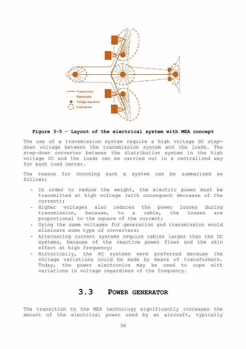
Considering that the generators are driven by shafts with
different rotation speeds, it is reasonable to convert all the
power generated in a single output of high voltage on the
distribution system. This system allows to reduce the weight of
the cables as paths to lower current; in the DC systems, in fact,
there is no reactive power flow and there is the skin effect due
to high frequency. In addition to the high voltage DC systems, the
systems will remain low voltage to power the apparatus dedicated
to the avionics. The Fig.1.5 shows a conceptual layout of the
electrical system on MEE four engines and two auxiliary power unit
(APU).
36
Figure 3-5 - Layout of the electrical system with MEA concept
The use of a transmission system require a high voltage DC step-
down voltage between the transmission system and the loads. The
step-down converter between the distribution system in the high
voltage DC and the loads can be carried out in a centralized way
for each load center.
The reason for choosing such a system can be summarized as
follows:
- In order to reduce the weight, the electric power must be
transmitted at high voltage (with consequent decrease of the
current);
- Higher voltages also reduces the power losses during
transmission, because, to a cable, the losses are
proportional to the square of the current;
- Using the same voltages for generation and transmission would
eliminate some type of converters;
- Alternating current systems require cables larger than the DC
systems, because of the reactive power flows and the skin
effect at high frequency;
- Historically, the AC systems were preferred because the
voltage variations could be made by means of transformers.
Today, the power electronics may be used to cope with
variations in voltage regardless of the frequency.
3.3 POWER GENERATOR
The transition to the MEA technology significantly increases the
amount of the electrical power used by an aircraft, typically
37
between 100-200 kW to over 1 MW for a large civil aircraft; this
increases the demand on the generating system. In order that the
MEA can be competitive in terms of weight and reliability of the
system, there has been a number of fundamental developments in the
generation of electricity on board. Below we will see some
examples of the generation of electricity.
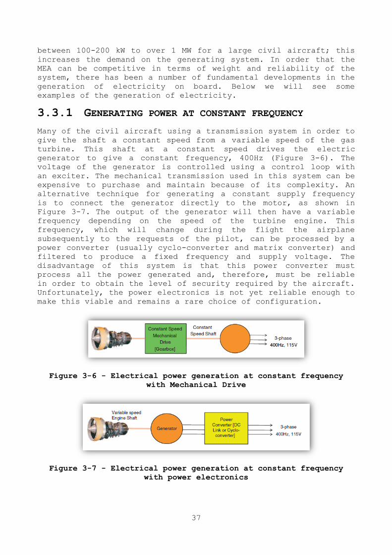
3.3.1 GENERATING POWER AT CONSTANT FREQUENCY
Many of the civil aircraft using a transmission system in order to
give the shaft a constant speed from a variable speed of the gas
turbine. This shaft at a constant speed drives the electric
generator to give a constant frequency, 400Hz (Figure 3-6). The
voltage of the generator is controlled using a control loop with
an exciter. The mechanical transmission used in this system can be
expensive to purchase and maintain because of its complexity. An
alternative technique for generating a constant supply frequency
is to connect the generator directly to the motor, as shown in
Figure 3-7. The output of the generator will then have a variable
frequency depending on the speed of the turbine engine. This
frequency, which will change during the flight the airplane
subsequently to the requests of the pilot, can be processed by a
power converter (usually cyclo-converter and matrix converter) and
filtered to produce a fixed frequency and supply voltage. The
disadvantage of this system is that this power converter must
process all the power generated and, therefore, must be reliable
in order to obtain the level of security required by the aircraft.
Unfortunately, the power electronics is not yet reliable enough to
make this viable and remains a rare choice of configuration.
Figure 3-6 - Electrical power generation at constant frequency
with Mechanical Drive
Figure 3-7 - Electrical power generation at constant frequency
with power electronics

38
3.3.2 GENERATING POWER AT VARIABLE FREQUENCY
If decade the need to have a fixed frequency electrical power, it
is possible to directly connect a generator to the motor, as shown
in Figure 3-8. The output of this generator provides a power
supply with a voltage-controlled variable frequency, typically in
the range 320-800 Hz. In this type of system, there is a direct
connection between the generator and the power bus, creating a
build configuration simple and reliable. The disadvantage of this
system is that almost all loads require power converters for the
control, since the variable frequency power supply cannot be
applied directly to most applications.
Figure 3-8 - Power Generating at variable frequency
3.4 MORE ELECTRIC ENGINE (MEE)
The technology behind the MEE concept can be described in the
following way:
- Using a motor / generator lightweight high power, high
efficiency, connected to each of the main shafts of an
engine, to provide electric energy to the system and remove
the hydraulic pump from the engine, thus simplifying the
interface engine / cabin.
It can be mounted outside of the turbine and connected to the main
shaft through reduction gears (option 'external'), or mounted
directly to the inside coaxially to the shaft (option 'internal').
There are several studies, dedicated to the integration of
electric motor/generators directly into the main gas turbine, acts
to reduce the overall complexity of the system, the fault
tolerance and with the objective of increasing the overall
efficiency of the system.
In this way, the transmission system at a constant speed (CVG), or
Integrated Drive Generators (IDG), may be partly or totally
eliminated. Consequently the frequency generated covers a wide
range depending on the change of engine speed.

39
Figure 3-9 – A Turbofan system
With reference to the structure of a turbofan engine (Figure 3-9)
it is possible to integrate the generator inside the main motor in
different positions. In particular, the generator can be operated
both by the low pressure (LP) and high pressure (HP). These two
possibilities involve different advantages and disadvantages,
mainly regarding the size, speed and environmental conditions of
work.
In integration HP shaft, the electric machine is characterized by
a lower weight, occupies a smaller room, and has a higher speed of
rotation of the shaft. Furthermore, this solution allows to use
the electric machine as a starter motor, avoiding in this way the
auxiliary system dedicated. However, because of the high inertia
of the turbine, is also required a high torque to the engine when
it is stationary.
The main disadvantage of integration onto HP is the tough
environmental conditions of exercise, due to the high temperature.
Using active magnetic bearings, which would replace the current
sphere system. These offer the possibility to remove the oil from
the engine system, which would lead to a drastic reduction of a
scheduled maintenance, a better control of engine vibrations,
since the trees would rotate around their centres of mass rather
than their geometrical centres, and a best engine diagnostics,
since the variations of signals in the feedback from the bearings
are used to control the movement dynamic shaft.
Using compressors and units of cooling/heating electrically
operated to pressurize and condition the air in the aircraft
cabin. These units may be powered by motors; the need to provide
air conditioning in the cabin in every situation (for example when
the main propulsion engines are stopped) would lead to prepare one
or more auxiliary power units (APU). The result is an improvement
40
of the environment in the cabin for the crew and passengers as
well as to a reduction of the emission of fuel.
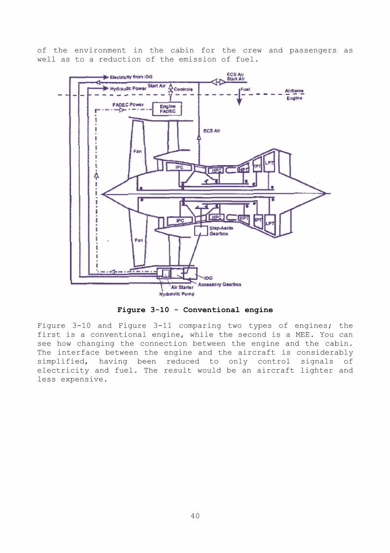
Figure 3-10 - Conventional engine
Figure 3-10 and Figure 3-11 comparing two types of engines; the
first is a conventional engine, while the second is a MEE. You can
see how changing the connection between the engine and the cabin.
The interface between the engine and the aircraft is considerably
simplified, having been reduced to only control signals of
electricity and fuel. The result would be an aircraft lighter and
less expensive.

41
Figure 3-11 - Engine with More Electric Engine Structure
3.5 SYSTEM SECURITY
It is of fundamental importance to the reliability of some
electrical drives in applications MEA and in particular for the
three main units:
1. electromechanical actuators for primary control of the flight surfaces;
2. electric fuel pump; 3. motor/generator integrated into the engine.

42
3.5.1 DRIVE FOR FLIGHT CONTROL APPLICATION
Modern aircrafts are used hydraulic actuators to move the
surfaces to control the flight. There are three basic degrees of
control of the aircraft for the flight (see Figure 3-12): roll,
pitch and yaw. The critical surfaces for the control of the flight
are respectively the ailerons, elevator and rudder which are then
referred to as the primary actuators. Other control surfaces such
as slats and flaps, are not critical to flight and, therefore,
referred to as secondary actuators.
Examples of these surfaces are shown in
Figure 3-13. The number and type of
actuators is very different compared to
the aircraft considered. Furthermore,
the load requirements are very
different: starting from a few
kilowatts to the lamellas of the edge,
up to 50-60 kW for the stabilizer
systems and vertical rudder. In
addition, the dynamic load profile may
be very different: there are few
surface movements that have great size
and short duration (typically during
landing and take-off) or "small"
superficial adjustment during flight.
In addition, abnormal performance can
be requested to the actuators in flight during some critical
conditions. For example, if all the engines on the same wing fail,
the actuator of the rudder must be able to keep the drawbar in a
fixed position, with a high yaw angle, during the flight. In this
situation, it is very high the torque required to the electric
motor.
Figure 3-13 - Wing control surfaces of a fixed-wing aircraft: 1.
wingtip, 2. Low speed aileron, 3. high speed aileron, 4. flap
track fairing, 5. Krüger flaps, 6.slats, 7. three slotted inner
flaps, 8. three slotted outer flaps, 9. spoilers, 10. spoilers
air-brakes
Figure 3-12 – Roll, pitch
and yaw are used to
describe the objects
orientation around each
of its axis

43
It is important to emphasize that the actuators have to work in
very harsh environmental conditions: temperature between -60°C and
+70°C and atmospheric pressure variable between 0 and 1 bar. Due
to the low thermal conductivity of the fuselage (composite
materials, sheet materials, etc.), the thermal exchanges between
the actuators and the environment must be carefully evaluated.
In a conventional fuselage, the drive system of the flight
surfaces is made by a centralized hydraulic system, consisting of
a hydraulic pump and a motor positioned in the fuselage as well as
to different pipelines of fluids and hydraulic actuators
positioned in the wings and in the tail. The control of hydraulic
actuators is realized with the consolidated technology of "fly-by-
wire" where there is no mechanical connection between the control
surfaces and the cockpit. Moving towards a scenario all electric
aircraft (AEA), the idea is to control each area with its own
electromechanical actuator directly coupled. This concept is
defined as "power-by-wire".
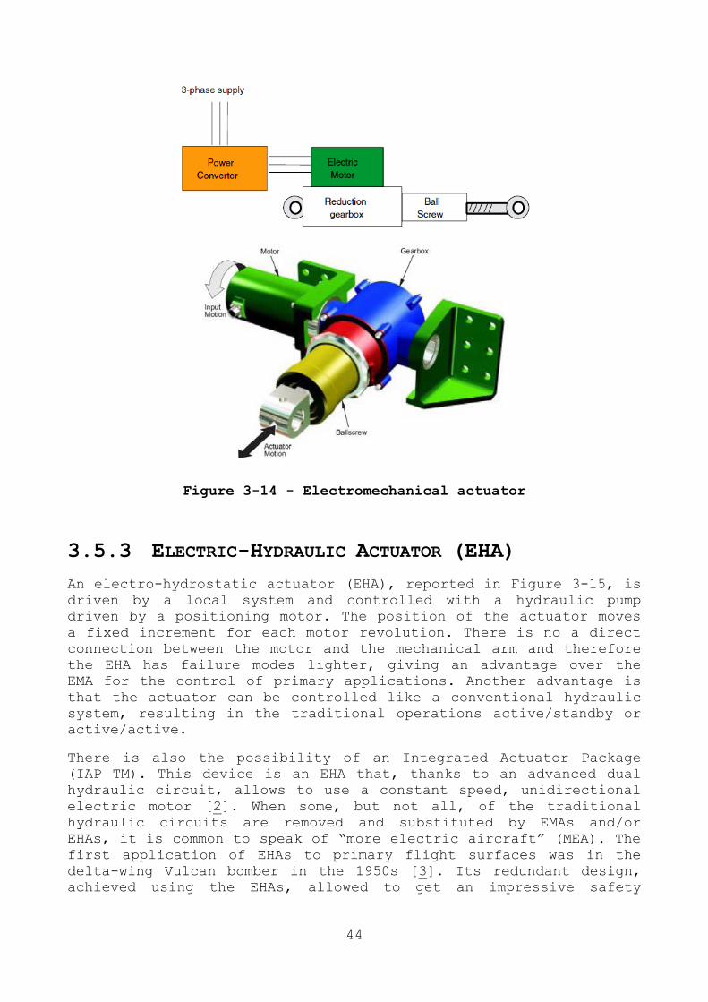
3.5.2 ELECTROMECHANICAL ACTUATORS (EMA)
When replacing hydraulic actuators with electric system, the
obvious choice is to use an electromechanical actuator (EMA), as
shown in Figure 3-14. In a system EMA, the surface is moved by
rotating a motor. At the same time, moves a system of ball screw
through a gear reducer. For each revolution of the motor moves the
actuator to a fixed quantity as there is a direct connection
between the motor and the arm. The problem in the distribution of
EMA MEA is that it is very difficult to ensure that the ball screw
can never problem. For this reason, aircraft manufacturers still
have some doubts in using the EMA preferring the more reliable
electro-hydraulic actuators (EHA).
44
Figure 3-14 - Electromechanical actuator
3.5.3 ELECTRIC-HYDRAULIC ACTUATOR (EHA)
An electro-hydrostatic actuator (EHA), reported in Figure 3-15, is
driven by a local system and controlled with a hydraulic pump
driven by a positioning motor. The position of the actuator moves
a fixed increment for each motor revolution. There is no a direct
connection between the motor and the mechanical arm and therefore
the EHA has failure modes lighter, giving an advantage over the
EMA for the control of primary applications. Another advantage is
that the actuator can be controlled like a conventional hydraulic
system, resulting in the traditional operations active/standby or
active/active.
There is also the possibility of an Integrated Actuator Package
(IAP TM). This device is an EHA that, thanks to an advanced dual
hydraulic circuit, allows to use a constant speed, unidirectional
electric motor [2]. When some, but not all, of the traditional
hydraulic circuits are removed and substituted by EMAs and/or
EHAs, it is common to speak of ―more electric aircraft‖ (MEA). The
first application of EHAs to primary flight surfaces was in the
delta-wing Vulcan bomber in the 1950s [3]. Its redundant design,
achieved using the EHAs, allowed to get an impressive safety

45
record. More recent example of commercial MEAs are the Boeing 787
and the Airbus A380.
Figure 3-15 - Example of large Electric-Hydraulic Actuator (EHA).
Source [2]
In the Boing 787, a mid-sized wide-body aircraft, spoilers and
horizontal stabilizer flight controls are operated by electric
motors in order to guarantee the control functionality also in the
case of a total hydraulics failure. The super-jumbo A380 represent
the state-of-art with respect to the flight control system.
Both EHAs and EMAs use an electric motor and a power converter and
a control system. [4]. With respect to the electric motor, a
Brushless DC (BLDC) and the switched Reluctance (SR) motors are
the more promising ones due to their lightweight, reliability
characteristics. It is commonly reported that a fault-tolerant
electric motor for EMA applications has to be guarantee
- High torque/weight radio;
- High torque/ampere radio;
- High efficiency in the full speed range;
- Electrical, thermal, magnetic and mechanical insulation
between the phases;
- Safe operation in faulty conditions (one phase loss).

46
Also the power converter topology is discussed and analysed in
literature. The proposed solutions regards the conventional
Voltage Source Inverters (VSIs) and a matrix converters. The
converter topology influence several aspects, such as the request
DC-Link capacitor in the VSIs (with weight problems [5] and power
quality management [6]) and the power quality issues for the
matrix converters [7].
3.6 ELECTRIC FUEL PUMP
The fuel pumps can be subdivided in two categories:
- The low pressure boost/transfer pump;
- The high pressure FCU (Fuel Control Unit) fuel pump.
The low pressure pump normally is electrically operated, while, in
traditional systems, the high pressure fuel pump is directly
driven through the mechanical gearbox and the fuel flux is
controlled by means of the fuel valve. As a consequence, the focus
is on the high pressure fuel pump because it is another aircraft
apparatus that could be electrically driven, introducing the
concept of ―smart electric fuel pump‖. The main advantage of the
electric solution for the fuel pump is in the possibility to drive
the pump at variable speed. In this way the pump can deliver a
variable fuel flux to the combustion chamber, in accordance to the
engine control requirements, eliminating the fuel valve in the
fuel metering system. The application of this new technology leads
to several advantages, such as weight saving, lower maintenance
costs and improved in-service reliability.
3.7 ON BOARD POWER GENERATION
On conventional civil aircraft, the electrical power is usually
generated by wound field synchronous generator with a permanent
magnet exciter stage. A generator control unit (GCU) performs a
field control in order to regulate the terminal voltage. The
generator is mechanically driven by the main engine shaft by of a
Constant Velocity Gearbox (CVG). In this way the CVG allowing to
maintain constant the frequency at 400Hz. If the CVG is integrate
inside the generator, it is called Integrated Drive Generator
(IDG).
In addition at the previous described energy generation system,
Auxiliary Power Units (APU) are presents on the aircraft. They are
small fuel burner jet engines connected to dedicated electrical
generators, aimed to supply vital loads in case of main engines or
generators failure. The APU also employed to provide electric

47
power in the pre-flight conditions, when the main aircraft engine
are still turned-off.
As back-up energy generation system, in addition at the APUs,
there are also the Ram Air Turbine (RATs) which are propellers
spanned by the high speed of the air flows near the airframe body
(Figure 3-16). They are extracted by airplane body only in
emergency conditions.
Figure 3-16 - An example of Ram Air Turbine (RAT) in on F-104S
Starfighter (Source: Wikipedia Commons) [8]
3.8 REGENERATION ENERGY ONTO THE ELECTRICAL
POWER BUS
An interesting system power could affect the ability to recover
energy from the electric actuators. This is possible when the
energy from the load circuit to the DC bus. Obviously, the amount
of energy depends on the profile of load and the duty cycle of the
actuator. Today this energy is dissipated on banks of resistors
connected on the intermediate stage of the converter, with
inevitable problems of weight and heat dissipation. Regeneration
may occur in an actuator when the surface is moved with an aiding
load or from the inertial energy when a motor is decelerated
rapidly.
A number of options have been identified that could allow the
power quality (voltage regulation) to be maintained whilst
allowing loads to regenerate power when required [9]:

48
1. Centralized energy storage – allow regeneration onto the
aircraft bus and have energy storage on the power bus for
when other loads are not present.
2. Centralized energy dissipation – allow regeneration onto the aircraft bus and have energy dissipation on the power bus for
when other loads are not present.
3. Local voltage control – allow regeneration onto the aircraft bus, but only if the voltage at the point of common coupling
is within defined limits.
4. Return energy to source – allow regeneration onto the
aircraft bus and use the generator as a motor if required,
the regenerative power would be returned to the engine
inertia.
5. Separate bus for regenerative energy – do not allow
regeneration onto the main aircraft bus, but add an
additional, relatively unregulated bus to distribute
regenerated power.
6. Local energy dissipation – do not allow regeneration onto the aircraft bus and ensure that each item of equipment has
energy dissipation if required.
7. Local energy storage – do not allow regeneration onto the
aircraft bus and have energy storage within each piece of
equipment.
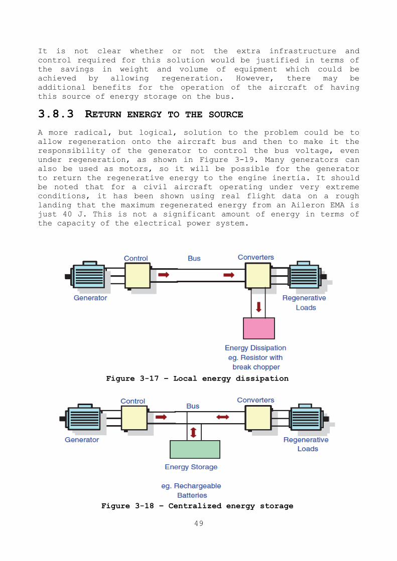
3.8.1 LOCAL ENERGY DISSIPATION
The solution used today, shown in Figure 3-17, is not to allow any
of electrical loads to regenerate energy onto the bus. If the load
has regenerative operations, this energy must be dissipated within
the power converters. This is usually achieved using a breaking
resister and chopper circuit. Whilst this system works well, the
resistor and associated cooling must be sized to cope with the
worst case operating condition. For this reason, the dissipative
elements add significant volume and weight to the power converter.
The advantages of this approach are that the generator and bus
will never see regeneration and, therefore, the risk of
uncontrolled voltage rise on the bus due to the loads is
eliminated.
3.8.2 CENTRALIZED ENERGY STORAGE
It is possible to arrange for each power bus to have an energy
storage facility in order to store the regenerated energy for use
later, as shown in Figure 3-18. This energy storage would have to
be controlled centrally in conjunction with the control of the
generator in order to maintain good control of the bus voltage.
This energy storage could be provided in the form or rechargeable
batteries or regenerative fuel cells. This energy can then be used
later in the flight to power the loads when they are in a motoring
operating condition.
49
It is not clear whether or not the extra infrastructure and
control required for this solution would be justified in terms of
the savings in weight and volume of equipment which could be
achieved by allowing regeneration. However, there may be
additional benefits for the operation of the aircraft of having
this source of energy storage on the bus.
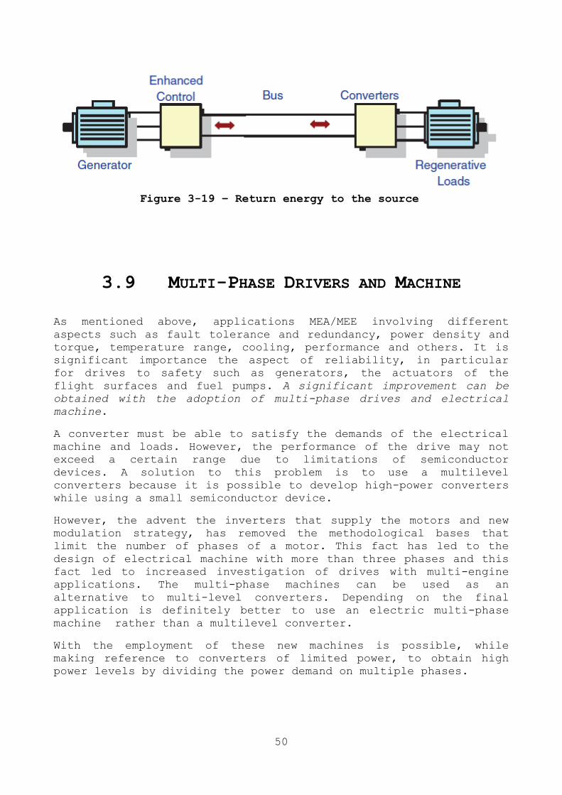
3.8.3 RETURN ENERGY TO THE SOURCE
A more radical, but logical, solution to the problem could be to
allow regeneration onto the aircraft bus and then to make it the
responsibility of the generator to control the bus voltage, even
under regeneration, as shown in Figure 3-19. Many generators can
also be used as motors, so it will be possible for the generator
to return the regenerative energy to the engine inertia. It should
be noted that for a civil aircraft operating under very extreme
conditions, it has been shown using real flight data on a rough
landing that the maximum regenerated energy from an Aileron EMA is
just 40 J. This is not a significant amount of energy in terms of
the capacity of the electrical power system.
Figure 3-17 – Local energy dissipation
Figure 3-18 – Centralized energy storage
50
Figure 3-19 – Return energy to the source
3.9 MULTI-PHASE DRIVERS AND MACHINE
As mentioned above, applications MEA/MEE involving different
aspects such as fault tolerance and redundancy, power density and
torque, temperature range, cooling, performance and others. It is
significant importance the aspect of reliability, in particular
for drives to safety such as generators, the actuators of the
flight surfaces and fuel pumps. A significant improvement can be
obtained with the adoption of multi-phase drives and electrical
machine.
A converter must be able to satisfy the demands of the electrical
machine and loads. However, the performance of the drive may not
exceed a certain range due to limitations of semiconductor
devices. A solution to this problem is to use a multilevel
converters because it is possible to develop high-power converters
while using a small semiconductor device.
However, the advent the inverters that supply the motors and new
modulation strategy, has removed the methodological bases that
limit the number of phases of a motor. This fact has led to the
design of electrical machine with more than three phases and this
fact led to increased investigation of drives with multi-engine
applications. The multi-phase machines can be used as an
alternative to multi-level converters. Depending on the final
application is definitely better to use an electric multi-phase
machine rather than a multilevel converter.
With the employment of these new machines is possible, while
making reference to converters of limited power, to obtain high
power levels by dividing the power demand on multiple phases.

51
52
Chapter 4
DESIGN OF A MULTIPHASE INDUCTION
MACHINE FOR AN OPEN ROTOR
AERO-ENGINE SHAFT LINE EMBEDDED
STARTER/GENERATOR
4.1 ABSTRACT
The aerospace world has found in electrification the way to
improve the efficiency, reliability and maintainability of an
aircraft. This idea leads to the aircraft a new management and
distribution of electrical services. On the other hand the fuel
saving targets is drawing the attention toward new architectures.
This chapter presents an method to design of a four-three-phase
fault tolerant induction machine to be installed on the high
pressure shaft of an open rotor jet engine. The integration of the
generator on shaft of this kind of engine challenges the electric
machine designer in facing, at the same time, the harsh
environment and high reliability requirements. The paper presents
the design of multi-phase fault tolerant induction machine to be
installed on the high pressure shaft of an open rotor jet engine.
In particular, the proposed solution is a four-three-phase
induction machine.
53
4.2 INTRODUCTION
In the transport sector the ―more electric‖ solutions are
gaining attention with the aims at increasing energy efficiency
and reliability leading to reduce emissions and maintenance costs.
Many examples can be found: from road transport, where hybrid
electric vehicles are gaining popularity [10] to the sea
transport.
In this general frame, aerospace applications have found that
the progressive electrification of on-board services is a way to
reduce or to remove the dependence on hydraulic, mechanical and
the bleed air/pneumatic system. The resulting step change in
aircraft electrical loads has far reaching implication for
electrical generation system.
The MEA approach has been widely discussed in the technical
literature and the topic has been included in many of the most
important international conferences and Journals [11]. One of the
dominant themes is that of fault tolerance. The fault tolerance,
together with the fault prevention, removal and forecasting, is
one of the means to achieve dependability [12]. The fault
tolerance is traditionally achieved by a complete parallel
actuation; transportation applications, where the size and weight
are important, demand optimized architectures including active
redundancies. In motor drives the fault tolerance can be enhanced
by phase modular redundancies; hence the interest toward
multiphase machines.
Next to the idea of electrification of the aircraft, the
worldwide aerospace research has been focus on new jet aero-
engines architectures with the aim of minimizing fuel consumption
and emissions: one of these architecture is the Open Rotor.
The goal of the idea is the optimal design a multi-phase fault
tolerant starter/generator suitable for the installation on the
high pressure shaft of a non-conventional jet aero-engine, with
Open Rotor (OR) architecture (Figure 4-1). In particular, it is a
four-three-phase induction machine designed for its integration to
the high pressure shaft in the rear part of the engine.
4.3 OPEN ROTOR JET ENGINES
During the last several decades worldwide aerospace research
has studied new aero-engines with the final aims if minimizing
aviation impact, reducing CO2 and NOX emissions [13] [14]. Some
project focus on the most advanced technologies to optimize
existing engines while others aim at the design of radical new
architectures [15]. In this scenario it has been extensively shown

54
that classical turbofan architectures, even if optimized, have
limits in the fuel saving potential, as efficiency improvements,
are mainly constrained by losses, drag, weight and noise [16] [17]
.
a) Direct Drive b) Geared Figure 4-1 - Qualitative geared Open Rotor engine architecture
Several OR concepts have been analysed since the 1980’s, and two
architectures seem to be the most promising ones: the direct-drive
and the geared one, where a reduction gearbox between the fan and
the low pressure shaft allows the latter to run at a higher speed.
Direct-drive configurations constrain the power turbine to rotate
at the same speed as the propellers, thus the turbine efficiency
cannot be the optimal one. Conversely, in the geared
configurations the power turbine can be released from the
propellers themselves, leading to an increase in its rotational
speed and, consequently, to a lower specific fuel consumption .
Furthermore a high-speed power turbine needs fewer stages than a
direct-drive, implying a smaller and lighter sub-system.
The Geared Open Rotor architecture (Figure 4-1) seems to be
the most promising radical architecture for future aircraft. In
fact the integration of the starter/generator in the shaft line of
the aero-engine, together with the electrification of the on-board
services, lead to the removal of the gearbox necessary to extract
the mechanical power for large part the on-board energy.
The integration of the starter/generator in the shaft line of
the aero-engine, together with the electrification of the on-board
services, leads to the removal of the heavy gearbox necessary to
extract the mechanical power for large part of the on-board
energy.
4.4 FAULT TOLERANT MULTI-PHASE DRIVES
Besides the well-known requirements related to the weight,
volume and reliability, the electric drives for aircraft
applications must also fulfil the fault tolerant operation.
Furthermore, the use of electric power as the unique on-board

55
energy vector requires improving the reliability of the
generators.
There is growing acceptance that conventional drive systems
will not be able to meet the reliability requirements and hence a
level of redundancy is essential [18]. The more recent studies on
the reliability of electromechanical actuators for MEA [19] have
demonstrated that the multi-phase drive topology gives more
advantages in terms of fault tolerant operation respect to the 3-
phase counterpart. Moreover same of these studies discuss that a
single multi-phase converter that supplies a multi-phase machine
using star connection does not fulfil the fault tolerant operation
required by the MEA applications [19]. To achieve true fault
tolerant operations, the most promising multi-phase electrical
machine configurations that can be used for the MEA applications
are:
Figure 4-2 - Fault tolerant
drive with multiple single-phase
units
Figure 4-3 - Fault tolerant
drive with multiple 3-phase
units
Multiple of independent single-phase units (Figure 4-2)
Multiple of independent 3-phase units (Figure 4-3)
Current power-supply systems in civil aircraft usually are 3-
phase voltage sources of 115V AC and the frequency can be constant
or can vary between 300Hz and 800Hz. In some applications the
voltage is now increased at 230V AC. Other solutions are DC
voltage supply at 350V or 540V, while the 270V DC is used in
military aircraft [20].
The candidate machines for the embedded starter/generator
application are Induction Machines (IMs), Switched Reluctance
Machines (SRMs) and Permanent Magnet Synchronous Machines (PMSMs).
It is accepted that PMSMs provide higher torque density than SRMs
and IMs, but they are less intrinsically fault tolerant [26]. The
not-eliminable presence of the back emf induced by the rotating
magnets poses severe problems in the faults management.

56
Furthermore the mechanical and thermal limits of the magnets could
be not compatible with the temperature constrains (including
demagnetization issues) of the application. On the other hand the
high speed and relatively low torque demanded by the application
make acceptable the lower torque density of the magnet less
solutions that show also a ―natural‖ flux weakening capability,
required by the constant power generation profile.
4.5 MACHINE DESIGN CRITERIA
When approaching the design of a high speed Induction Machine
(IM), the main constraints are the required output power, both as
motor and generator, the maximum rotational speed of the rotor and
furthermore the mechanical requirements, which are the dynamic
stiffness and the vibration limits [21]. Further constraints are
the torque overload capability at start-up and the power overload
capability as generator at high speed. Therefore, a compromise
must be found between electromagnetic and mechanical constraints.
Furthermore, the maximum operating frequency is limited by the
thermal stresses of the power electronic components and by the
machine iron losses, taking the air-gap flux density and the
number of poles into account.
On the basis of the previous considerations, the following
constraints have been adopted for the optimized design.
Air-gap mean diameter lower than 150 mm
Inner rotor diameter greater than 70 mm
Stator slot pitch greater than 8 mm
Air-gap width greater than 0.8 mm
4.6 DESIGN PROCEDURE
As is known, the main dimensions of the IM are related to the
apparent power A and torque T by the following relationships [28]
√
(4-1)
√ (4-2)
where is the operating frequency, L and D represent the axial length and the air-gap mean diameter, and are the peak value

57
of the air-gap flux density and linear current density, is the
pole pairs number and and are the winding factor, the efficiency and the power factor, respectively.
As is possible to see from (4-1) and (4-2), for given value of
the required performance, the main dimensions L and D depend on
the basic design parameters and .
The number of stator slots must be a multiple of the number of
phases. In order to produce a sinusoidal distribution of the
magnetomotive force at the air-gap, a distributed winding with an
integer number q of slot per pole per phase should be chosen. The greater the number of stator slots the lower the value of the slot
pitch. Due to the presence of the slot opening, increasing the
number of slots the air-gap permeance will decrease, due to the
increasing influence of the Carter’s coefficient.
For a given number of stator slots, the number of the rotor
slots must be chosen taking care of the magnetic interaction
between stator and rotor teeth [22].The number of conductors per
slot n is given by
√
(4-3)
where represents the rms value of the voltage applied to one of the phase winding.
By assuming a high value of the iron permeability, the
constitutive relationships of the IM allows the calculation of the
outer diameter of the stator once the surface current density J
and the flux density Bfe in the teeth and in the yoke are
selected.
These relationships equate the flux in a tooth to the flux in
the slot pitch where the mean air-gap flux density is BM.
Particular attention should be given in cases where a very high
value of the flux density may be chosen. In these cases a non-
negligible magnetic flux will flow also through the slot and it
must be considered. Further relationships equate the flux in the
yoke to the half of the flux per pole . The radial
dimension of the slot is calculated on the basis of the teeth
dimensions taking the current in a slot , the value of and the slot fill factor into consideration. The last one must be
conservative, in respect of the reliability of the application.
The same considerations apply for the calculation of the inner
diameter of the rotor. In this case, the rotor bar currents are
calculated by using the power factor of the machine.
Once the overall dimensions are calculated, the equivalent
circuit of the machine may be built, allowing the determination of

58
the characteristic curves of the machine, both in motor as well as
in generator operation. The resulting performance may match, or
not, the target design and constraints. In the positive case the
design is a candidate for the optimization. In the negative case
the design is discarded and new values of the design choices must
be adopted.
Obviously, when performing the above described procedure, the
final design must be consistent with the assumptions made in (4-1)
and (4-2).
The characteristics of the optimized machine will strongly depend
on the adopted active material stress. This, in turn, depends on
the properties of the magnetic material. With reference to the
target application, the Fe-Co alloys represent an optimal choice
for the realization of the magnetic circuit [30]. In particular,
reference is made to VACOFLUX 50, strip 0.2 mm, supplied by
VACUUMSCHMELZE GmbH & Co. KG. The B-H curve adopted here for the
design optimization is shown in Figure 4-4.
Figure 4-4 - B-H Curve of the magnetic alloy used for stator and
rotor lamination
From Figure 4-4 it is possible to see that, using this alloy, the
allowable flux density in the magnetic circuit can reach values up
to 2 T and more, with very high relative values of the
permeability, so avoiding iron saturation.
The specific losses of the magnetic material are calculated as
a function of the local maximum value of the flux density B. On
the basis of the properties of the chosen material, the iron
0
0.25
0.5
0.75
1
1.25
1.5
1.75
2
2.25
2.5
2.75
0 10000 20000 30000 40000 50000 60000 70000 80000 90000
B [
T]
H [A/m]
B-H Curve of ferromagnetic material

59
losses have been calculated with reference to Figure 4-5, were a
suitable coefficient has been included, considering the effects of
annealing and of the hardening of the sheet due to the punching
operation.
Figure 4-5 - Specific iron losses as a function of the maximum
value of the flux density, including annealing conditions and the
punching effects
The copper losses can be easily calculated at low frequency while
at high frequency the skin effect strongly influence these losses.
To reduce the skin effect, the thickness of a conductor in slot
must be limited to proper thin level, which requires increasing
the number of conductors in the slot height direction [23]
4.7 TARGET DESIGN AD PROTOTYPE
The candidate machines for the embedded starter/generator
application are Induction Machines (IMs), Switched Reluctance
Machines (SRMs) and Permanent Magnet Synchronous Machines (PMSMs).
It is accepted that PMSMs provide higher torque density than SRMs
and IMs, but they are less intrinsically fault tolerant. The not-
eliminable presence of the back emf induced by the rotating
magnets poses severe problems in the faults management.
Furthermore the mechanical and thermal limits of the magnets
(including demagnetization issues) could be not compatible with
the temperature constrains of the application (including the
thermal soak-back phenomenon at engine stop). On the other hand
the high speed and relatively low torque demanded by the
application make acceptable the lower torque density of the
magnetless solutions that show also a ―natural‖ flux weakening
capability, required by the constant power generation profile.
A suitable machine model of the quadruple three-phase IM was
derived in [24] by exploiting the potentialities of a specific

60
space vector transformation. The inherent degrees of freedom of
the multiphase drive have been emphasized defining a technique for
current sharing management among the four three-phase stator
windings. The total machine electric power can be split among the
four DC sources in a flexible way, with the usage of several
degrees of freedom.
In [24] the authors investigate potentialities of the four-
three-phase squirrel cage 100kVA induction machine characterized
by the specifications listed in Table I. The high flux density of
the Fe-Co alloys let to design lighter magnetic cores with
different optimal trade-offs between copper and iron. For this
reason Fe-Co laminations are rather common in the electric machine
production for aerospace applications. The high speed of the
motor-generator implies fundamental frequencies that bring the
specific iron losses in the range of 50-100 W/kg. To cope with
this issue together with the high cost and high specific weight of
the material, can be convenient the reduction of the flux density
in the stator core. This fact prevents the utter exploitation of
the high flux density capability of the material, making viable
the use of conventional Fe-Si lamination for the stator core; on
the contrary, it is out of discussion the use of the Fe-Co alloy
in the rotor, where the frequencies are low, letting the full
exploitation of the material and more room for the copper or
aluminum conductors
To investigate the potential improvement of the use of the Fe-
Co lamination in the rotor core, in comparison with a total Fe-Si
machine two scaled prototypes have been designed and realized. The
used Fe-Co material is the VACOFLUX 50, supplied by VACUUMSCHMELZE
GmbH & Co, while the Fe-Si lamination is the NO 20 supplied by
Cogent Power Ltd. Both laminations have a thickness of 0.2 mm. In
order to reduce the manufacturing costs of the prototypes, and to
simplify the comparison, the same active length (80 mm), the same
inner (110 mm) and outer (200 mm) diameter of the stator were
adopted. The numbers of stator (48) and rotor (40) slots have been
also assumed equal, as well as the slot fill factor.
For both the scaled-size prototypes the targets for the wanted
performances are listed in Table II.
The performed design process allowed to find solutions with
high efficiencies with acceptable power factors and thermal
compatibility. The main differences of the two final designs are
shown in Table III. For display purposes, Figure 4-6 allows to
compare the two rotor laminations. As it is possible to see in
Table III, the higher magnetic saturation level of the Cobalt Iron
alloy led to thinner width of the stator and rotor teeth of the
FeCo prototype even if it was designed with a lower number of
conductors per slot which means a higher value of flux per pole.
As a result of the design process, the expected rated performances
of the two machines, for generator and motor operations, are as
reported in Table IV and Table V, respectively. The manufacturing

61
process was performed by Electrical Discharge Machining (EMD) of
the stator and rotor laminations. Then, the die cast rotors and
the twelve phase wounded stators have been locked in the housing
having shields equipped with ball bearings designed for the
required high rotational speed. Also included were the temperature
probes and the incremental encoders.
Table 4-1 - Characteristics of the Scaled Prototypes
Starter/Generator
Number of phases 12 (4x3-phase, star connected)
Rated voltage of each 3-ph system 186 Vrms
Constant V/Hz operation up to 267 Hz
Generating mode
Continuous output power 10 kVA
Constant power range 6000 to 15000 rpm
Overload 150% 5 min., 200% 5 sec
Cooling system air, forced ventilation.
Table 4-2 - Differences in the Design-Result of the two Prototypes
Fe-Si rotor Fe-Co rotor
Stator tooth width 3.8 mm 3.6 mm
Stator yoke width 18 mm 20 mm
Conductor per slot 19 17
Rotor tooth width 3.8 mm 3.0 mm
Rotor yoke width 14 mm 16 mm
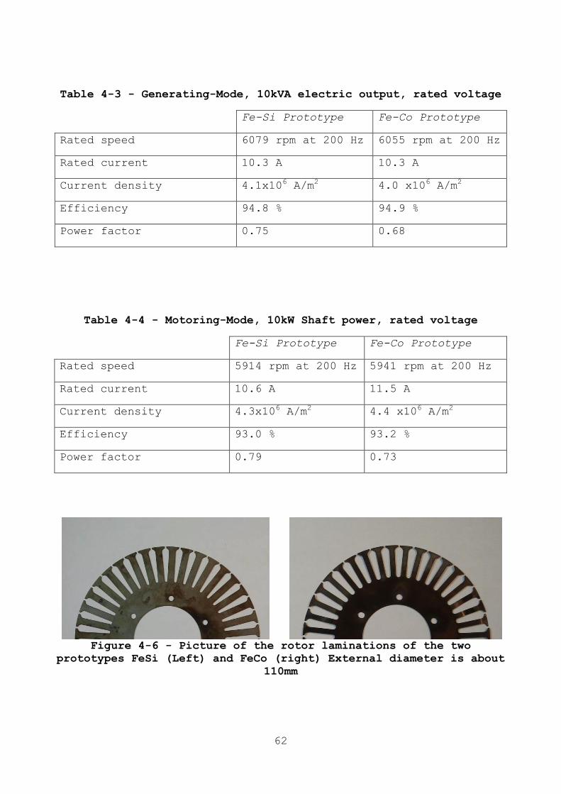
62
Table 4-3 - Generating-Mode, 10kVA electric output, rated voltage
Fe-Si Prototype Fe-Co Prototype
Rated speed 6079 rpm at 200 Hz 6055 rpm at 200 Hz
Rated current 10.3 A 10.3 A
Current density 4.1x10⁶ A/m
2 4.0 x10
6 A/m
2
Efficiency 94.8 % 94.9 %
Power factor 0.75 0.68
Table 4-4 - Motoring-Mode, 10kW Shaft power, rated voltage
Fe-Si Prototype Fe-Co Prototype
Rated speed 5914 rpm at 200 Hz 5941 rpm at 200 Hz
Rated current 10.6 A 11.5 A
Current density 4.3x10⁶ A/m
2 4.4 x10
6 A/m
2
Efficiency 93.0 % 93.2 %
Power factor 0.79 0.73
Figure 4-6 - Picture of the rotor laminations of the two
prototypes FeSi (Left) and FeCo (right) External diameter is about
110mm

63
4.8 EQUIVALENT CIRCUIT PARAMETERS
MEASUREMENTS
For both the investigated prototypes the parameters of the
electric equivalent circuits have been experimentally determined
by the well-known no-load and locked rotor test [25]. The
prototypes have been tested connecting the stator windings in
three-phase mode, star connection, and using a programmable
sinusoidal power supply (rated 40 kVA, 0-520 V, 50-300 Hz, voltage
THD < 0.1%). Then, the machine parameters have been referred to
the 12-phases connection.
4.8.1 NO LOAD TESTS
Six no-load tests have been performed changing the frequency
from 50 Hz up to 300 Hz, with steps of 50 Hz. Due to the voltage
limitation of the available power source, for frequency higher
than 150 Hz it was not possible to get the rated flux conditions,
and the maximum available supply voltage was used as reference
voltage for the test elaborations.
Table 4-5 - No-Load test result for the Fe-Si 12 Phase Prototype
Frequency, (Hz) 50 100 150 200 250 300
12-phases ref. voltage,(V) 46.5 93 130 130 130 130
No-load current, (A) 5.54 5.59 5.06 3.54 2.77 2.29
Iron losses, (W) 30.5 85.3 105 103 97.4 91.6
Mechanic. losses, (W) 20.4 45.1 65.5 105 161 256
Table 4-6 - No-Load test result for the Fe-Co 12 Phase Prototype
Frequency, (Hz) 50 100 150 200 250 300
12-phases ref. voltage,(V) 46.5 93 130 130 130 130
No-load current, (A) 5.54 5.59 5.06 3.54 2.77 2.29
Iron losses, (W) 30.5 85.3 105 103 97.4 91.6
Mechanic. losses, (W) 20.4 45.1 65.5 105 161 256
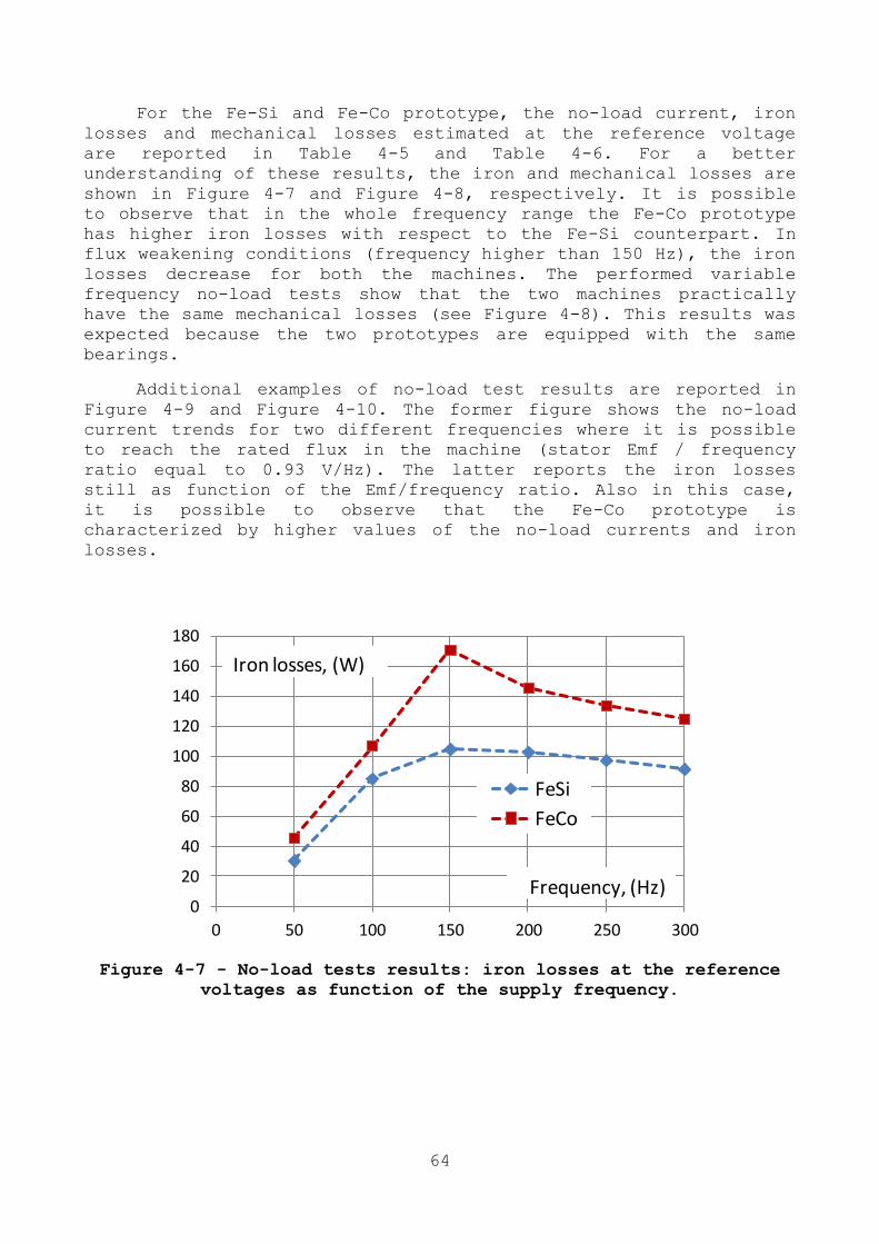
64
For the Fe-Si and Fe-Co prototype, the no-load current, iron
losses and mechanical losses estimated at the reference voltage
are reported in Table 4-5 and Table 4-6. For a better
understanding of these results, the iron and mechanical losses are
shown in Figure 4-7 and Figure 4-8, respectively. It is possible
to observe that in the whole frequency range the Fe-Co prototype
has higher iron losses with respect to the Fe-Si counterpart. In
flux weakening conditions (frequency higher than 150 Hz), the iron
losses decrease for both the machines. The performed variable
frequency no-load tests show that the two machines practically
have the same mechanical losses (see Figure 4-8). This results was
expected because the two prototypes are equipped with the same
bearings.
Additional examples of no-load test results are reported in
Figure 4-9 and Figure 4-10. The former figure shows the no-load
current trends for two different frequencies where it is possible
to reach the rated flux in the machine (stator Emf / frequency
ratio equal to 0.93 V/Hz). The latter reports the iron losses
still as function of the Emf/frequency ratio. Also in this case,
it is possible to observe that the Fe-Co prototype is
characterized by higher values of the no-load currents and iron
losses.
Figure 4-7 - No-load tests results: iron losses at the reference
voltages as function of the supply frequency.
0
20
40
60
80
100
120
140
160
180
0 50 100 150 200 250 300
FeSi
FeCo
Iron losses, (W)
Frequency, (Hz)
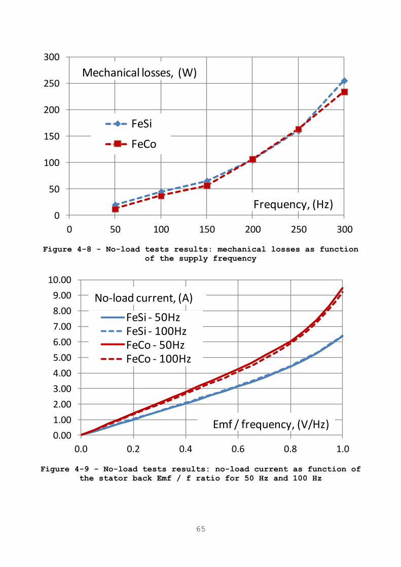
65
Figure 4-8 - No-load tests results: mechanical losses as function
of the supply frequency
Figure 4-9 - No-load tests results: no-load current as function of
the stator back Emf / f ratio for 50 Hz and 100 Hz
0
50
100
150
200
250
300
0 50 100 150 200 250 300
FeSi
FeCo
Mechanical losses, (W)
Frequency, (Hz)
0.00
1.00
2.00
3.00
4.00
5.00
6.00
7.00
8.00
9.00
10.00
0.0 0.2 0.4 0.6 0.8 1.0
FeSi - 50HzFeSi - 100HzFeCo - 50HzFeCo - 100Hz
No-load current, (A)
Emf / frequency, (V/Hz)
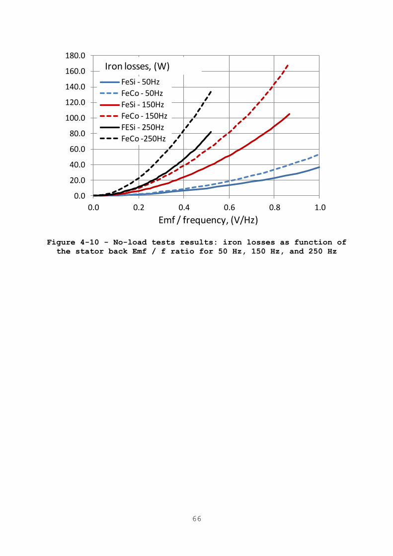
66
Figure 4-10 - No-load tests results: iron losses as function of
the stator back Emf / f ratio for 50 Hz, 150 Hz, and 250 Hz
0.0
20.0
40.0
60.0
80.0
100.0
120.0
140.0
160.0
180.0
0.0 0.2 0.4 0.6 0.8 1.0
FeSi - 50Hz
FeCo - 50Hz
FeSi - 150Hz
FeCo - 150Hz
FESi - 250Hz
FeCo -250Hz
Iron losses, (W)
Emf / frequency, (V/Hz)
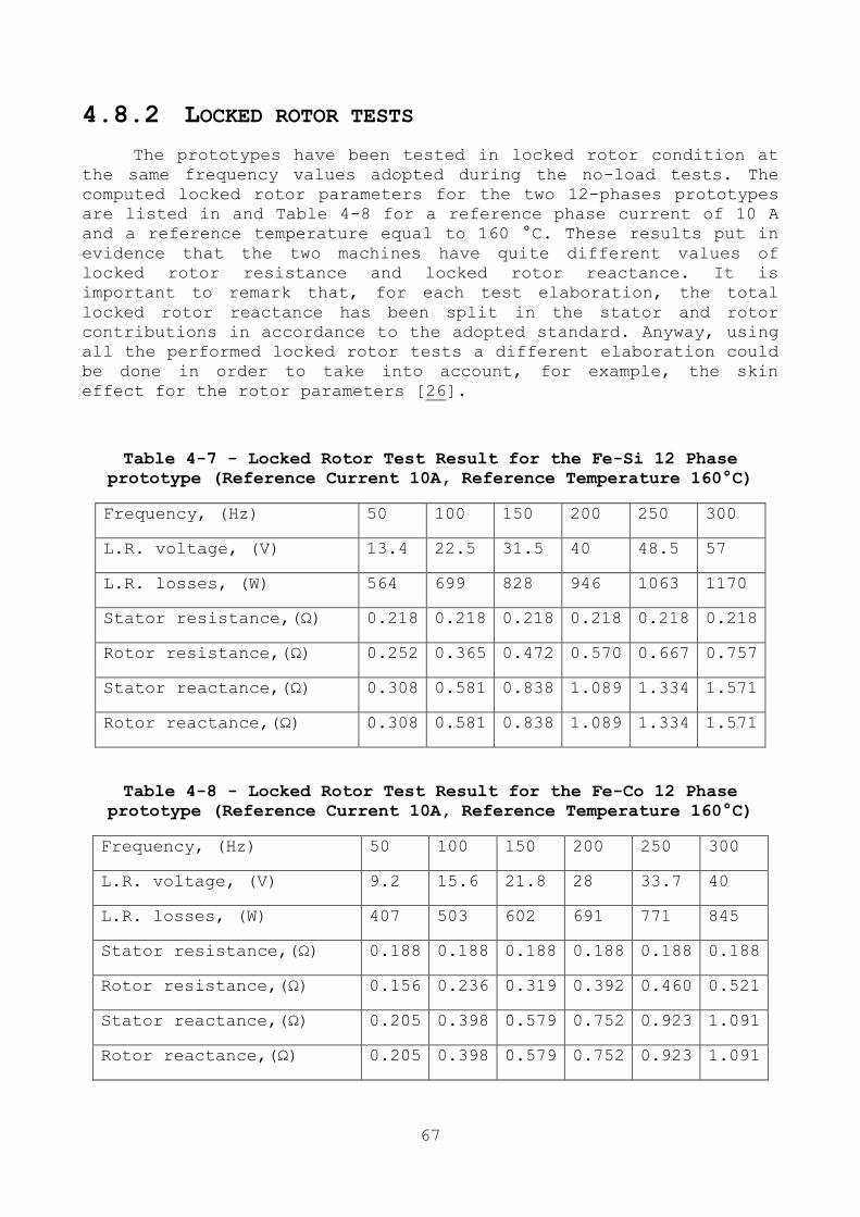
67
4.8.2 LOCKED ROTOR TESTS
The prototypes have been tested in locked rotor condition at
the same frequency values adopted during the no-load tests. The
computed locked rotor parameters for the two 12-phases prototypes
are listed in and Table 4-8 for a reference phase current of 10 A
and a reference temperature equal to 160 °C. These results put in
evidence that the two machines have quite different values of
locked rotor resistance and locked rotor reactance. It is
important to remark that, for each test elaboration, the total
locked rotor reactance has been split in the stator and rotor
contributions in accordance to the adopted standard. Anyway, using
all the performed locked rotor tests a different elaboration could
be done in order to take into account, for example, the skin
effect for the rotor parameters [26].
Table 4-7 - Locked Rotor Test Result for the Fe-Si 12 Phase
prototype (Reference Current 10A, Reference Temperature 160°C)
Frequency, (Hz) 50 100 150 200 250 300
L.R. voltage, (V) 13.4 22.5 31.5 40 48.5 57
L.R. losses, (W) 564 699 828 946 1063 1170
Stator resistance,(Ω) 0.218 0.218 0.218 0.218 0.218 0.218
Rotor resistance,(Ω) 0.252 0.365 0.472 0.570 0.667 0.757
Stator reactance,(Ω) 0.308 0.581 0.838 1.089 1.334 1.571
Rotor reactance,(Ω) 0.308 0.581 0.838 1.089 1.334 1.571
Table 4-8 - Locked Rotor Test Result for the Fe-Co 12 Phase
prototype (Reference Current 10A, Reference Temperature 160°C)
Frequency, (Hz) 50 100 150 200 250 300
L.R. voltage, (V) 9.2 15.6 21.8 28 33.7 40
L.R. losses, (W) 407 503 602 691 771 845
Stator resistance,(Ω) 0.188 0.188 0.188 0.188 0.188 0.188
Rotor resistance,(Ω) 0.156 0.236 0.319 0.392 0.460 0.521
Stator reactance,(Ω) 0.205 0.398 0.579 0.752 0.923 1.091
Rotor reactance,(Ω) 0.205 0.398 0.579 0.752 0.923 1.091
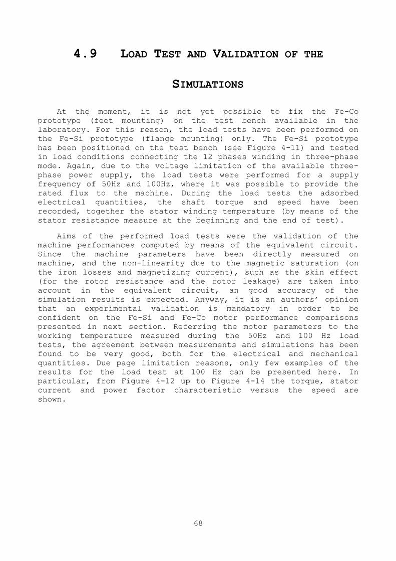
68
4.9 LOAD TEST AND VALIDATION OF THE
SIMULATIONS
At the moment, it is not yet possible to fix the Fe-Co
prototype (feet mounting) on the test bench available in the
laboratory. For this reason, the load tests have been performed on
the Fe-Si prototype (flange mounting) only. The Fe-Si prototype
has been positioned on the test bench (see Figure 4-11) and tested
in load conditions connecting the 12 phases winding in three-phase
mode. Again, due to the voltage limitation of the available three-
phase power supply, the load tests were performed for a supply
frequency of 50Hz and 100Hz, where it was possible to provide the
rated flux to the machine. During the load tests the adsorbed
electrical quantities, the shaft torque and speed have been
recorded, together the stator winding temperature (by means of the
stator resistance measure at the beginning and the end of test).
Aims of the performed load tests were the validation of the
machine performances computed by means of the equivalent circuit.
Since the machine parameters have been directly measured on
machine, and the non-linearity due to the magnetic saturation (on
the iron losses and magnetizing current), such as the skin effect
(for the rotor resistance and the rotor leakage) are taken into
account in the equivalent circuit, an good accuracy of the
simulation results is expected. Anyway, it is an authors’ opinion
that an experimental validation is mandatory in order to be
confident on the Fe-Si and Fe-Co motor performance comparisons
presented in next section. Referring the motor parameters to the
working temperature measured during the 50Hz and 100 Hz load
tests, the agreement between measurements and simulations has been
found to be very good, both for the electrical and mechanical
quantities. Due page limitation reasons, only few examples of the
results for the load test at 100 Hz can be presented here. In
particular, from Figure 4-12 up to Figure 4-14 the torque, stator
current and power factor characteristic versus the speed are
shown.
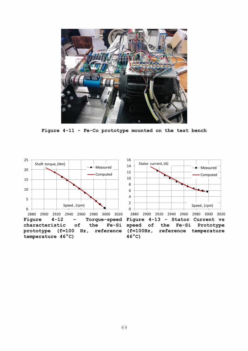
69
Figure 4-11 - Fe-Co prototype mounted on the test bench
Figure 4-12 – Torque-speed
characteristic of the Fe-Si
prototype (f=100 Hz, reference
temperature 46°C)
Figure 4-13 - Stator Current vs
speed of the Fe-Si Prototype
(f=100Hz, reference temperature
46°C)
0
5
10
15
20
25
2880 2900 2920 2940 2960 2980 3000 3020
Measured
Computed
Shaft torque, (Nm)
Speed , (rpm)0
2
4
6
8
10
12
14
16
2880 2900 2920 2940 2960 2980 3000 3020
Measured
Computed
Shaft torque, (Nm)Stator current, (A)
Speed , (rpm)
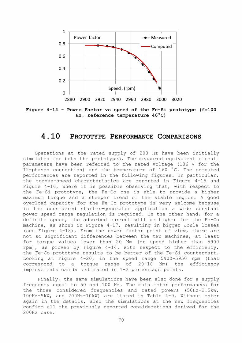
70
Figure 4-14 - Power Factor vs speed of the Fe-Si prototype (f=100
Hz, reference temperature 46°C)
4.10 PROTOTYPE PERFORMANCE COMPARISONS
Operations at the rated supply of 200 Hz have been initially
simulated for both the prototypes. The measured equivalent circuit
parameters have been referred to the rated voltage (186 V for the
12-phases connection) and the temperature of 160 °C. The computed
performances are reported in the following figures. In particular,
the torque-speed characteristics are reported in Figure 4-15 and
Figure 4-16, where it is possible observing that, with respect to
the Fe-Si prototype, the Fe-Co one is able to provide a higher
maximum torque and a steeper trend of the stable region. A good
overload capacity for the Fe-Co prototype is very welcome because
in the considered starter-generator application a wide constant
power speed range regulation is required. On the other hand, for a
definite speed, the adsorbed current will be higher for the Fe-Co
machine, as shown in Figure 4-17, resulting in bigger Joule losses
(see Figure 4-18). From the power factor point of view, there are
not so significant differences between the two machines, at least
for torque values lower than 20 Nm (or speed higher than 5900
rpm), as proven by Figure 4-14. With respect to the efficiency,
the Fe-Co prototype results to be better of the Fe-Si counterpart.
Looking at Figure 4-20, in the speed range 5900-5950 rpm (that
correspond to a torque range of 20-10 Nm) the efficiency
improvements can be estimated in 1-2 percentage points.
Finally, the same simulations have been also done for a supply
frequency equal to 50 and 100 Hz. The main motor performances for
the three considered frequencies and rated powers (50Hz-2.5kW,
100Hz-5kW, and 200Hz-10kW) are listed in Table 4-9. Without enter
again in the details, also the simulations at the new frequencies
confirm all the previously reported considerations derived for the
200Hz case.
0
0.2
0.4
0.6
0.8
1
2880 2900 2920 2940 2960 2980 3000 3020
Measured
Computed
Shaft torque, (Nm)Power factor
Speed , (rpm)
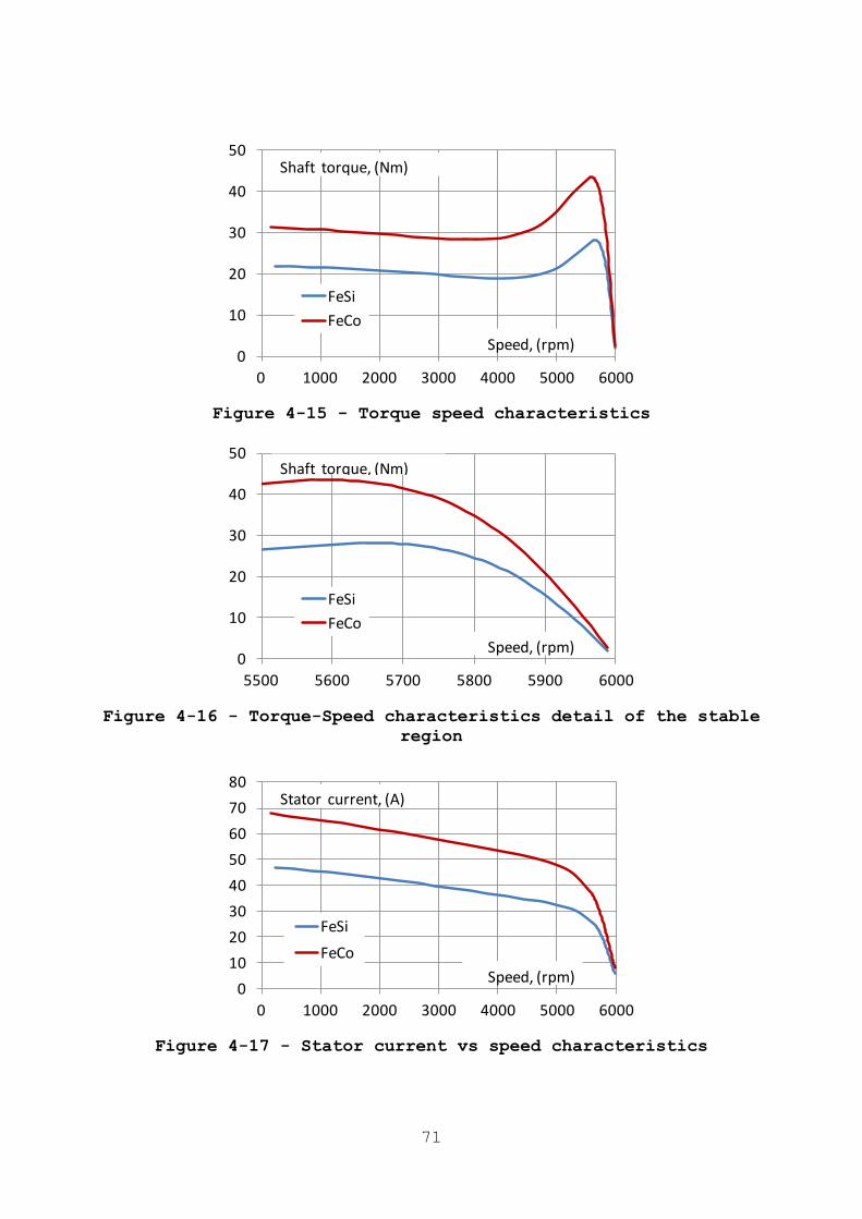
71
Figure 4-15 - Torque speed characteristics
Figure 4-16 - Torque-Speed characteristics detail of the stable
region
Figure 4-17 - Stator current vs speed characteristics
0
10
20
30
40
50
0 1000 2000 3000 4000 5000 6000
FeSi
FeCo
Shaft torque, (Nm)
Speed, (rpm)
0
10
20
30
40
50
5500 5600 5700 5800 5900 6000
FeSi
FeCo
Shaft torque, (Nm)
Speed, (rpm)
0
10
20
30
40
50
60
70
80
0 1000 2000 3000 4000 5000 6000
FeSi
FeCo
Stator current, (A)
Speed, (rpm)
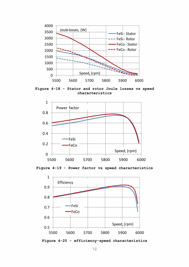
72
Figure 4-18 - Stator and rotor Joule losses vs speed
characteristics
Figure 4-19 - Power factor vs speed characteristics
Figure 4-20 - efficiency-speed characteristics
0
500
1000
1500
2000
2500
3000
3500
4000
5500 5600 5700 5800 5900 6000
FeSi - Stator
FeSi - Rotor
FeCo - Stator
FeCo - Rotor
Joule losses, (W)
Speed, (rpm)
Joule losses, (W)
Speed, (rpm)
Joule losses, (W)
Speed, (rpm)
Joule losses, (W)
Speed, (rpm)
0
0.2
0.4
0.6
0.8
1
5500 5600 5700 5800 5900 6000
FeSi
FeCo
Power factor
Speed, (rpm)
0.5
0.6
0.7
0.8
0.9
1
5500 5600 5700 5800 5900 6000
FeSi
FeCo
Efficiency
Speed, (rpm)
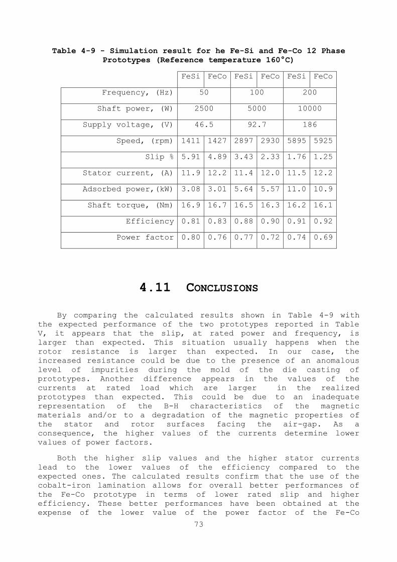
73
Table 4-9 - Simulation result for he Fe-Si and Fe-Co 12 Phase
Prototypes (Reference temperature 160°C)
FeSi FeCo FeSi FeCo FeSi FeCo
Frequency, (Hz) 50 100 200
Shaft power, (W) 2500 5000 10000
Supply voltage, (V) 46.5 92.7 186
Speed, (rpm) 1411 1427 2897 2930 5895 5925
Slip % 5.91 4.89 3.43 2.33 1.76 1.25
Stator current, (A) 11.9 12.2 11.4 12.0 11.5 12.2
Adsorbed power,(kW) 3.08 3.01 5.64 5.57 11.0 10.9
Shaft torque, (Nm) 16.9 16.7 16.5 16.3 16.2 16.1
Efficiency 0.81 0.83 0.88 0.90 0.91 0.92
Power factor 0.80 0.76 0.77 0.72 0.74 0.69
4.11 CONCLUSIONS
By comparing the calculated results shown in Table 4-9 with
the expected performance of the two prototypes reported in Table
V, it appears that the slip, at rated power and frequency, is
larger than expected. This situation usually happens when the
rotor resistance is larger than expected. In our case, the
increased resistance could be due to the presence of an anomalous
level of impurities during the mold of the die casting of
prototypes. Another difference appears in the values of the
currents at rated load which are larger in the realized
prototypes than expected. This could be due to an inadequate
representation of the B-H characteristics of the magnetic
materials and/or to a degradation of the magnetic properties of
the stator and rotor surfaces facing the air-gap. As a
consequence, the higher values of the currents determine lower
values of power factors.
Both the higher slip values and the higher stator currents
lead to the lower values of the efficiency compared to the
expected ones. The calculated results confirm that the use of the
cobalt-iron lamination allows for overall better performances of
the Fe-Co prototype in terms of lower rated slip and higher
efficiency. These better performances have been obtained at the
expense of the lower value of the power factor of the Fe-Co

74
prototype. Finally, it must be noted that, as it is shown in
Figure 4-15 and Figure 4-16, the maximum torque and the peak value
of the output power of the Fe-Co prototype are greatly better than
that of Fe-Si prototype, ensuring an improved reliability during
overload operations.
The next step will be the development of the third scaled machine
with both the stator and the rotor cores made of Fe-Co
laminations, to assess the advantages and the drawbacks of the
different choices.

75

76
Chapter 5
DYNAMIC STATOR CURRENT SHARING IN
QUADRUPLE THREE-PHASE INDUCTION
MOTOR DRIVE
5.1 ABSTRACT
In this chapter, a Field Oriented Control scheme for torque
and rotor flux regulation of a quadruple three-phase induction
machine is presented. Each three-phase stator winding is
independently supplied by a conventional three-phase inverter. The
presented motor drive can be utilized in medium and high power
systems. Furthermore, owing to the intrinsic redundant structure,
it can be employed for applications requiring a high degree of
reliability, such as More Electric Aircraft. A specific machine
model is achieved by introducing a proper multiple space vector
transformation, suitable for the particular stator winding
arrangement of the machine. Furthermore, exploiting the degrees of
freedom of the system, a current sharing management technique
among the four three-phase stator windings is presented. In this
way, a flexible power flow control can be employed. The modulation
strategy of the four three-phase inverters is based on the
principle of three-phase decomposition. The effectiveness of the
presented control scheme is verified by means of numerical
simulations

77
5.2 INTRODUCTION
Multi-phase motor drives have many advantages with respect to
their three-phase counterparts. In particular, the load power can
be split into multiple phases, leading to Voltage Source Inverters
(VSIs) having switching devices with limited power and current
rating. Furthermore, the additional degrees of freedom related to
a higher number of phases of the drive can be successfully
exploited in different ways, such as increasing the electrical
machine torque density, developing multi-motor drives, and
improving the fault tolerant capability [27], [28]. Nowadays,
multiphase drives are recognized as a viable approach for high-
power applications and can be employed in systems in which a high
degree of reliability is required.
Among the multiphase drives, the multiple three-phase ones are
particularly attractive, since they exploit the well-known three-
phase technology for the conversion structure. Dual, triple and
quadruple three-phase machines have been employed in several
applications [29], [30], [31], [32]. Owing to their redundant
structure, multiple three-phase drives ensure a high degree of
fault tolerant capability, which is appreciated in some critical
applications, such as More Electric Aircraft (MEA). The MEA
technology is based on the idea of replacing hydraulic and
pneumatic actuators with their corresponding electromagnetic
counterparts [33]. In particular, the aeronautic propulsion system
can be improved, according to the More Electric Engine (MEE)
philosophy, adopting an electric multiphase starter-generator
embedded within the main aircraft engine [34]. This multiphase
machine can be used as a motor for the starting and as generator
during the flight. The key advantages of MEE are the removal of
the hydraulic pumps and of pneumatic starting system, and the
optimization of the operation of the aircraft motor.
In this chapter, a quadruple three-phase induction motor drive
is presented. In the machine, four three-phase stator windings
with isolated neutral points, supplied independently by four two-
level three-phase VSIs with separated dc sources, are arranged in
the stator slots with a spatial shift of 15° electrical degrees. A
schematic draw of the induction motor drive is illustrated in Fig.
1. Note that, the four VSIs can be supplied also by only one dc
source. The description of the quadruple three-phase machine is
not trivial, due to the magnetic coupling among the four three-
phase windings. Therefore, a suitable machine model is derived by
exploiting the potentialities of an opportune multiple space
vector transformation. The proposed transformation can be
considered a generalization of the one presented in [35] for a
dual three-phase machine.
A conventional Field Oriented Control (FOC) scheme is adopted
for torque and rotor flux regulation, whereas the additional
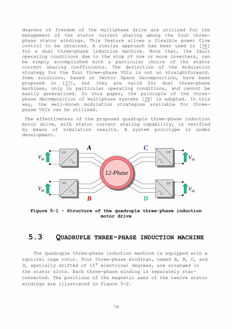
78
degrees of freedom of the multiphase drive are utilized for the
management of the stator current sharing among the four three-
phase stator windings. This feature allows a flexible power flow
control to be obtained. A similar approach has been used in [36]
for a dual three-phase induction machine. Note that, the fault
operating conditions due to the stop of one or more inverters, can
be simply accomplished with a particular choice of the stator
current sharing coefficients. The definition of the modulation
strategy for the four three-phase VSIs is not so straightforward.
Some solutions, based on Vector Space Decomposition, have been
proposed in [37], but they are valid for dual three-phase
machines, only in particular operating conditions, and cannot be
easily generalized. In this paper, the principle of the three-
phase decomposition of multiphase systems [38] is adopted. In this
way, the well-known modulation strategies available for three-
phase VSIs can be utilized.
The effectiveness of the proposed quadruple three-phase induction
motor drive, with stator current sharing capability, is verified
by means of simulation results. A system prototype is under
development.
Figure 5-1 - Structure of the quadruple three-phase induction
motor drive
5.3 QUADRUPLE THREE-PHASE INDUCTION MACHINE
The quadruple three-phase induction machine is equipped with a
squirrel cage rotor. Four three-phase windings, named A, B, C, and
D, spatially shifted of 15° electrical degrees, are arranged in
the stator slots. Each three-phase winding is separately star-
connected. The positions of the magnetic axes of the twelve stator
windings are illustrated in Figure 5-2.
Vdc
Vdc
Vdc
Vdc
12-Phase
A
B
C
D
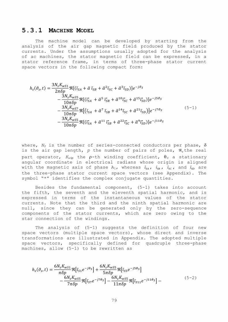
79
5.3.1 MACHINE MODEL
The machine model can be developed by starting from the
analysis of the air gap magnetic field produced by the stator
currents. Under the assumptions usually adopted for the analysis
of ac machines, the stator magnetic field can be expressed, in a
stator reference frame, in terms of three-phase stator current
space vectors in the following compact form:
[ ]
[
]
[( )]
[
]
(5-1)
where, NS is the number of series-connected conductors per phase, is the air gap length, p the number of pairs of poles, e the real
part operator, KwS the -th winding coefficient, S a stationary
angular coordinate in electrical radians whose origin is aligned
with the magnetic axis of phase A1, whereas SAi , SBi , SCi , and SDi are
the three-phase stator current space vectors (see Appendix). The
symbol ―*‖ identifies the complex conjugate quantities.
Besides the fundamental component, (5-1) takes into account
the fifth, the seventh and the eleventh spatial harmonic, and is
expressed in terms of the instantaneous values of the stator
currents. Note that the third and the ninth spatial harmonic are
null, since they can be generated only by the zero-sequence
components of the stator currents, which are zero owing to the
star connection of the windings.
The analysis of (5-1) suggests the definition of four new
space vectors (multiple space vectors), whose direct and inverse
transformations are illustrated in Appendix. The adopted multiple
space vectors, specifically defined for quadruple three-phase
machines, allow (5-1) to be rewritten as
[
]
[
]
[
]
[
]
(5-2)
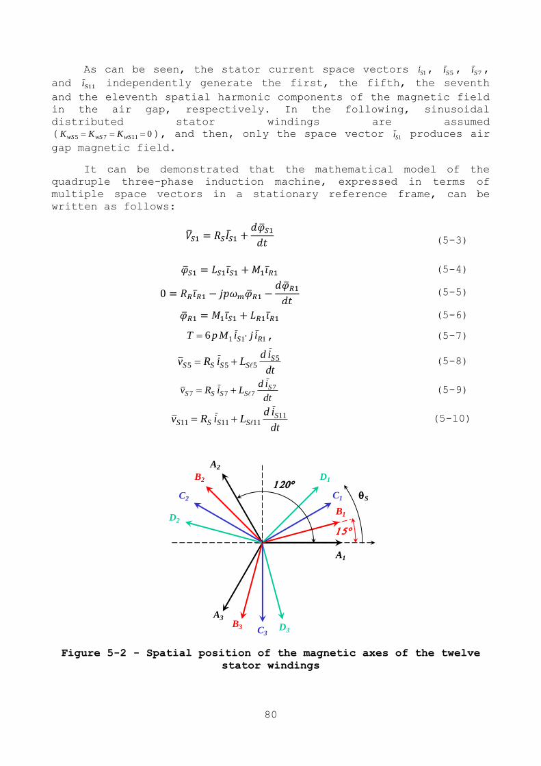
80
As can be seen, the stator current space vectors 1Si , 5Si , 7Si ,
and 11Si independently generate the first, the fifth, the seventh
and the eleventh spatial harmonic components of the magnetic field
in the air gap, respectively. In the following, sinusoidal
distributed stator windings are assumed
( 01175 wSwSwS KKK ), and then, only the space vector 1Si produces air
gap magnetic field.
It can be demonstrated that the mathematical model of the
quadruple three-phase induction machine, expressed in terms of
multiple space vectors in a stationary reference frame, can be
written as follows:
(5-3)
(5-4)
(5-5)
(5-6)
1116 RS ijiMpT , (5-7)
dt
idLiRv S
SSSS5
555
(5-8)
dt
idLiRv S
SSSS7
777
(5-9)
dt
idLiRv S
SSSS11
111111
(5-10)
Figure 5-2 - Spatial position of the magnetic axes of the twelve
stator windings
S
15
A1
A3
A2
B1
B2
B3
C1C2
C3
D1
D2
D3
120

81
where LS1, LR1, and M1 are respectively the stator, the rotor, and
the mutual inductances of 1-1 plane, whereas 5SL , 7SL , and 11SL
are the stator leakage inductances of 5-5, 7-7, and 11-11 planes.
Four decoupled sets of equations can be recognized. The first
one, i.e., (5-3) - (5-7), concerns the variables of the 1-1
plane, namely the variables involved in the electromagnetic
conversion process and then in torque and air-gap flux generation.
The second one, the third one, and the fourth one, represented by
(5-8), (5-9) and (5-10), are related to the variables of 5-5, 7-
7, and 11-11 planes (auxiliary variables), respectively.
As can be seen, the control of torque and flux is achieved by
acting on the space vector 1Sv in the 1-1 plane. However, also the
space vectors 5Sv , 7Sv , and 11Sv , in the other - planes, must be
taken contemporarily under control, since they define the current
sharing among the four three-phase stator windings, as
demonstrated in follow section.
5.3.2 THREE-PHASE SPACE VECTOR
The behaviour of the quadruple three-phase induction machine
can be described in terms of four three-phase space vectors, one
for each three-phase stator winding. The well-known linear
transformations are
163
821
3
2 AAAA xxxx
(5-11)
163
821
3
2 BBBB xxxx
(5-12)
163
821
3
2 CCCC xxxx
(5-13)
163
821
3
2 DDDD xxxx
(5-14)
Note that, =exp(j/12). The zero-sequence components are null due to the four isolated neutral points
5.3.3 MULTIPLE SPACE VECTORS
A more useful model of the quadruple three-phase induction
machine can be achieved by introducing four specific space vectors
(multiple space vectors), which are defined according to the
82
arrangement of the stator windings in the slots. The linear
transformations are the following
321
4
1 DCBA xxxxy
(5-15)
151055
4
1 *
D*C
*B
*A xxxxy
(5-16)
211477
4
1 DCBA xxxxy
(5-17)
9221111
4
1 *
D*C
*B
*A xxxxy
(5-18)
where the symbol ―*‖ identifies the complex conjugate operator.
The corresponding inverse transformations are
**A yyyyx 11751 (5-19)
1111
177
55
231 **
B yyyyx (5-20)
2211
107
105
221 **
C yyyyx (5-21)
911
37
155
211 **
D yyyyx (5-22)
5.4 STATOR AND CURRENT SHARING CONTROL
STRATEGY
In this Section, a control strategy able to control the stator
current sharing is presented. Since machine equations (5-3) -
(5-7) are similar to that of a three-phase induction machine, a
conventional FOC scheme can be adopted to control torque and rotor
flux. Therefore, the stator current vector 1Si depends on the drive
operating condition, i.e., torque reference, rotor flux reference,
and rotor speed. On the contrary, the auxiliary stator current
vectors 5Si , 7Si , and 11Si can be considered as degrees of freedom,
and can be exploited in order to manage the current sharing among
the four three-phase stator windings.
According to (5-19), the space vector 1Si of the stator current can
be expressed as
83
321
4
1 SDSCSBSAS iiiii (5-23)
In order to minimize the amplitude of the stator currents, the
four contributions in the right hand of (5-23) must be in phase,
leading to
14 SASA iKi (5-24)
114 SBSB iKi (5-25)
214 SCSC iKi (5-26)
314 SDSD iKi (5-27)
where KA, KB, KC and KD are the current sharing coefficients, which
must satisfy the following constraint:
(5-28)
Taking the transformations (5-20) - (5-22), and (5-24) - (5-27)
into account, leads to the following relationships:
*SDCBAS iKjKKjKi 15 (5-29)
17 SDCBAS iKjKKjKi (5-30)
*SDCBAS iKKKKi 111 (5-31)
The relationships (5-29) - (5-31), valid in the stationary
reference frame, give the instantaneous values of the auxiliary
stator current vectors, according to the required current sharing.
It should be noted that, in the particular case of KA=KB=KC=KD=1/4,
i.e., balanced stator current sharing, all the auxiliary stator
current vectors are null. It can be demonstrated that, when the
degree of unbalance is small, the current sharing coefficients can
be considered as instantaneous power sharing coefficients, with
good accuracy.
5.5 CONTROL SCHEME
The block diagram of the control scheme ensuring a decoupled
regulation of torque, rotor flux and stator current sharing is
emphasized in Figure 5-3.

84
Figure 5-3 - Block diagram of the control scheme
5.5.1 TORQUE AND ROTOR FLUX CONTROL
According to the well-known FOC principle, torque and rotor flux
control is achieved by acting on the q and d components of the
stator current, in a synchronous reference frame S+ having the d
axis aligned with the rotor flux 1R . The angle is the argument
of the estimated rotor flux. The PI current regulators PI(c) and
PI(d), which are adopted for the current tracking, calculate the d
and q components of the reference voltage vector ref,Sv 1 ,
respectively. The corresponding - components ref,Sv 1 , and ref,Sv 1 are
obtained through an opportune rotation.
5.5.2 AUXILIARY STATOR CURRENT CONTROL
In order to achieve a zero steady-state tracking error, the
control of the auxiliary stator current vectors must be
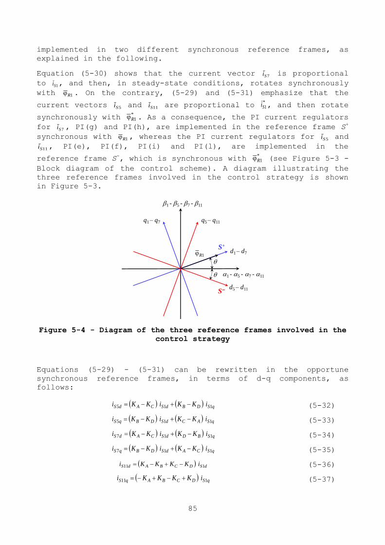
85
implemented in two different synchronous reference frames, as
explained in the following.
Equation (5-30) shows that the current vector 7Si is proportional
to 1Si , and then, in steady-state conditions, rotates synchronously
with 1R . On the contrary, (5-29) and (5-31) emphasize that the
current vectors 5Si and 11Si are proportional to *Si 1, and then rotate
synchronously with *R1 . As a consequence, the PI current regulators
for 7Si , PI(g) and PI(h), are implemented in the reference frame S+
synchronous with 1R , whereas the PI current regulators for 5Si and
11Si , PI(e), PI(f), PI(i) and PI(l), are implemented in the
reference frame S-, which is synchronous with
*R1 (see Figure 5-3 -
Block diagram of the control scheme). A diagram illustrating the
three reference frames involved in the control strategy is shown
in Figure 5-3.
Figure 5-4 - Diagram of the three reference frames involved in the
control strategy
Equations (5-29) - (5-31) can be rewritten in the opportune
synchronous reference frames, in terms of d-q components, as
follows:
qSDBdSCAdS iKKiKKi 115 (5-32)
qSACdSDBqS iKKiKKi 115 (5-33)
qSBDdSCAdS iKKiKKi 117 (5-34)
qSCAdSDBqS iKKiKKi 117
(5-35)
dSDCBAdS iKKKKi 111
(5-36)
qSDCBAqS iKKKKi 111 (5-37)
1 - 5 - 7 - 11
1 - 5 - 7 - 11
d1 – d7
q1 – q7
d5 – d11
q5 – q11
1RS+
S
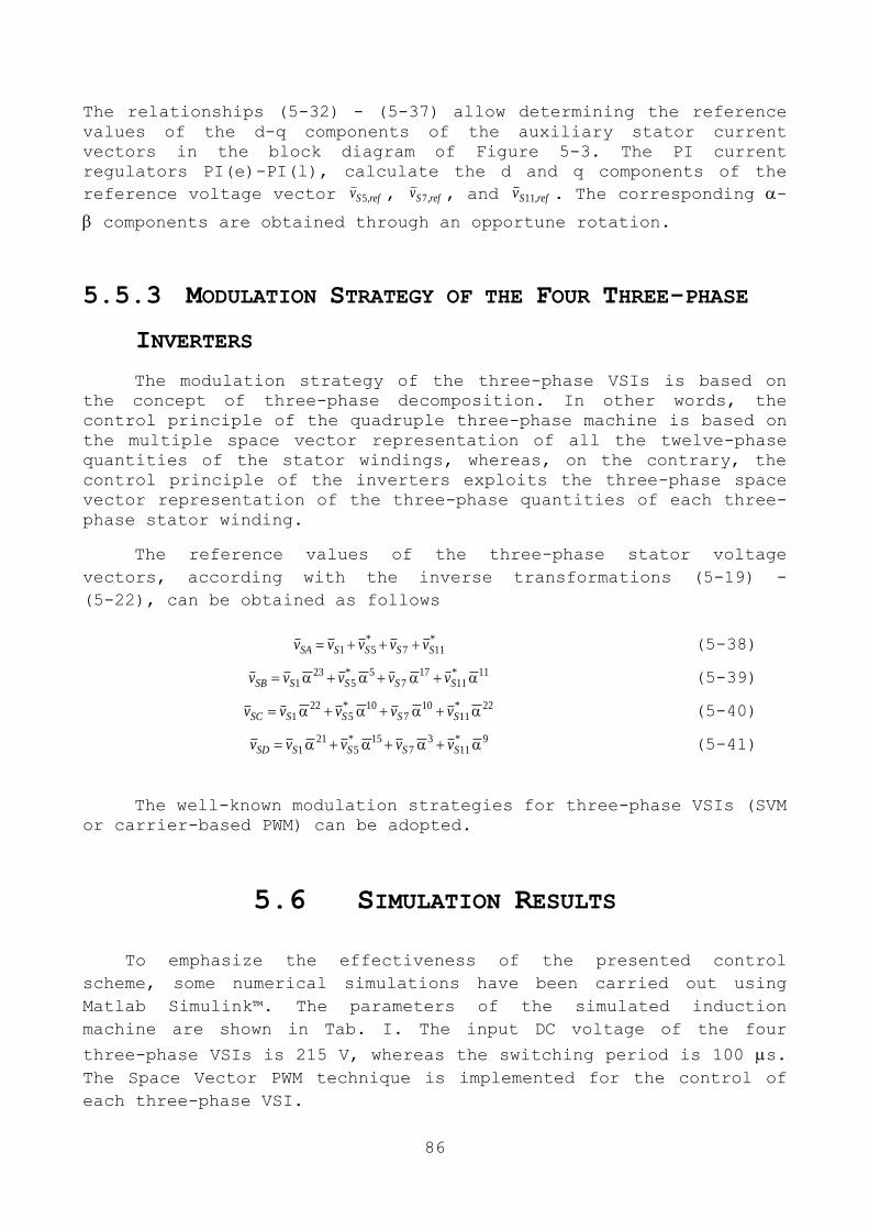
86
The relationships (5-32) - (5-37) allow determining the reference
values of the d-q components of the auxiliary stator current
vectors in the block diagram of Figure 5-3. The PI current
regulators PI(e)-PI(l), calculate the d and q components of the
reference voltage vector ref,Sv 5 , ref,Sv 7 , and ref,Sv 11 . The corresponding -
components are obtained through an opportune rotation.
5.5.3 MODULATION STRATEGY OF THE FOUR THREE-PHASE
INVERTERS
The modulation strategy of the three-phase VSIs is based on
the concept of three-phase decomposition. In other words, the
control principle of the quadruple three-phase machine is based on
the multiple space vector representation of all the twelve-phase
quantities of the stator windings, whereas, on the contrary, the
control principle of the inverters exploits the three-phase space
vector representation of the three-phase quantities of each three-
phase stator winding.
The reference values of the three-phase stator voltage
vectors, according with the inverse transformations (5-19) -
(5-22), can be obtained as follows
*SS
*SSSA vvvvv 11751 (5-38)
1111
177
55
231 *
SS*SSSB vvvvv (5-39)
2211
107
105
221 *
SS*SSSC vvvvv (5-40)
911
37
155
211 *
SS*SSSD vvvvv
(5-41)
The well-known modulation strategies for three-phase VSIs (SVM
or carrier-based PWM) can be adopted.
5.6 SIMULATION RESULTS
To emphasize the effectiveness of the presented control
scheme, some numerical simulations have been carried out using
Matlab Simulink™. The parameters of the simulated induction
machine are shown in Tab. I. The input DC voltage of the four
three-phase VSIs is 215 V, whereas the switching period is 100 s.
The Space Vector PWM technique is implemented for the control of
each three-phase VSI.
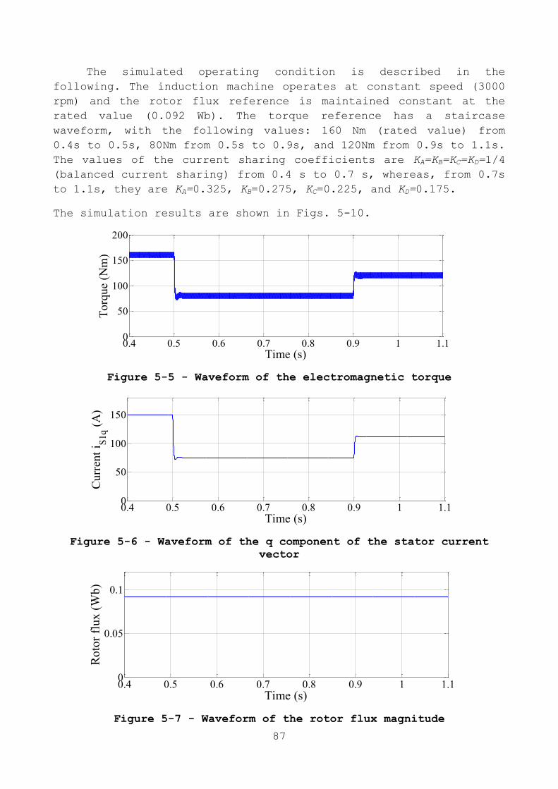
87
The simulated operating condition is described in the
following. The induction machine operates at constant speed (3000
rpm) and the rotor flux reference is maintained constant at the
rated value (0.092 Wb). The torque reference has a staircase
waveform, with the following values: 160 Nm (rated value) from
0.4s to 0.5s, 80Nm from 0.5s to 0.9s, and 120Nm from 0.9s to 1.1s.
The values of the current sharing coefficients are KA=KB=KC=KD=1/4
(balanced current sharing) from 0.4 s to 0.7 s, whereas, from 0.7s
to 1.1s, they are KA=0.325, KB=0.275, KC=0.225, and KD=0.175.
The simulation results are shown in Figs. 5-10.
Figure 5-5 - Waveform of the electromagnetic torque
Figure 5-6 - Waveform of the q component of the stator current
vector
Figure 5-7 - Waveform of the rotor flux magnitude
0.4 0.5 0.6 0.7 0.8 0.9 1 1.10
50
100
150
200
Time (s)
Torq
ue
(Nm
)
0.4 0.5 0.6 0.7 0.8 0.9 1 1.10
50
100
150
Time (s)
Cu
rren
t i S
1q (
A)
0.4 0.5 0.6 0.7 0.8 0.9 1 1.10
0.05
0.1
Time (s)
Ro
tor
flu
x (
Wb
)
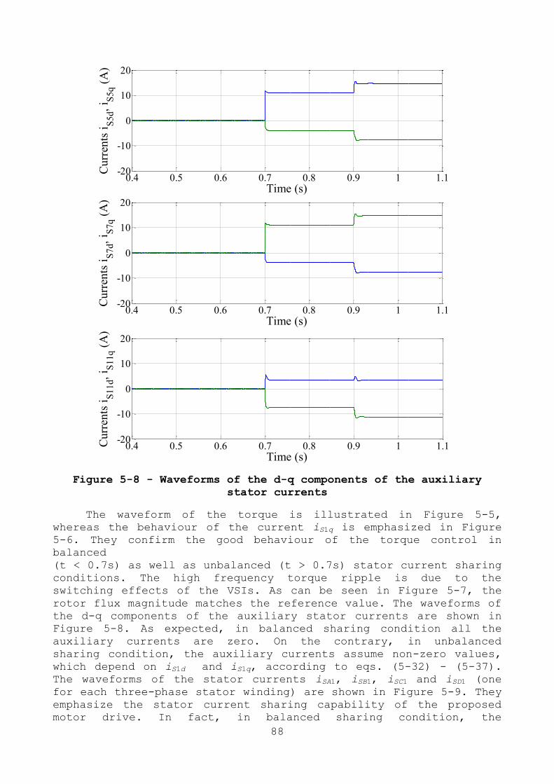
88
Figure 5-8 - Waveforms of the d-q components of the auxiliary
stator currents
The waveform of the torque is illustrated in Figure 5-5,
whereas the behaviour of the current iS1q is emphasized in Figure
5-6. They confirm the good behaviour of the torque control in
balanced
(t < 0.7s) as well as unbalanced (t > 0.7s) stator current sharing
conditions. The high frequency torque ripple is due to the
switching effects of the VSIs. As can be seen in Figure 5-7, the
rotor flux magnitude matches the reference value. The waveforms of
the d-q components of the auxiliary stator currents are shown in
Figure 5-8. As expected, in balanced sharing condition all the
auxiliary currents are zero. On the contrary, in unbalanced
sharing condition, the auxiliary currents assume non-zero values,
which depend on iS1d and iS1q, according to eqs. (5-32) - (5-37).
The waveforms of the stator currents iSA1, iSB1, iSC1 and iSD1 (one
for each three-phase stator winding) are shown in Figure 5-9. They
emphasize the stator current sharing capability of the proposed
motor drive. In fact, in balanced sharing condition, the
0.4 0.5 0.6 0.7 0.8 0.9 1 1.1-20
-10
0
10
20
Time (s)
Curr
ents
iS
5d,
i S5q (
A)
0.4 0.5 0.6 0.7 0.8 0.9 1 1.1-20
-10
0
10
20
Time (s)
Curr
ents
iS
7d,
i S7q (
A)
0.4 0.5 0.6 0.7 0.8 0.9 1 1.1-20
-10
0
10
20
Time (s)
Cu
rren
ts i
S11d,
i S11q (
A)

89
amplitudes of the currents are the same, whereas, in unbalanced
sharing condition, the amplitudes are different, in agreement with
the values of the sharing coefficients. The filtered values (time
constant = 500 s) of the instantaneous stator power of the four
three-phase windings are illustrated in Figure 5-10. These
waveforms confirm that the current sharing coefficients can
regarded as power sharing coefficients.
Figure 5-9 - Waveforms of some stator currents. a) Current iSA1,
b) current iSB1, c) current iSC1, and d) current iSD1.
0.4 0.5 0.6 0.7 0.8 0.9 1 1.1-200
-100
0
100
200
Time (s)
Curr
ent
i SA
1 (
A)
0.4 0.5 0.6 0.7 0.8 0.9 1 1.1-200
-100
0
100
200
Time (s)
Curr
ent
i SB
1 (
A)
0.4 0.5 0.6 0.7 0.8 0.9 1 1.1-200
-100
0
100
200
Time (s)
Curr
ent
i SC
1 (
A)
0.4 0.5 0.6 0.7 0.8 0.9 1 1.1-200
-100
0
100
200
Time (s)
Curr
ent
i SD
1 (
A)

90
Figure 5-10 - Filtered values (time constant 500us) of the
instantaneous stator powers of the four three-phase windings
5.7 CONCLUSION
In this chapter, a motor drive for medium and high power
applications, based on a quadruple three-phase induction machine,
has been presented. Four two-level VSIs independently supply the
three-phase stator windings. The machine model has been achieved
by introducing an opportune multiple space vector transformation,
suitable for the particular stator winding arrangement. Exploiting
the inherent degrees of freedom of the multiphase drive, a current
sharing management technique among the four three-phase stator
windings has been presented. Since, the current sharing
coefficients can be regarded as power sharing coefficients, the
proposed control algorithm allows total motor power to be split
among the four dc sources, in a flexible way, with three degrees
of freedom. The three-phase decomposition method has been employed
in order to establish the modulation strategy of the four three-
phase VSIs. The stator current sharing capability of the proposed
quadruple three-phase induction motor drive has been emphasized by
means of simulation results. A system prototype is under
development, and some experimental results will be presented in a
future work
0.4 0.5 0.6 0.7 0.8 0.9 1 1.10
5000
10000
15000
Time (s)
PS
A,
PS
B,
PS
C,
PS
D (
W)

91
92
Chapter 6
A MODULATION STRATEGY FOR MATRIX
CONVERTER WITH EXTENDED CONTROL
RANGE AND REDUCED SWITCHING POWER
LOSSES
6.1 ABSTRACT
This paper is focused on the enhancement of the control range
of matrix converters (MCs) operating with non-unity input power
factor and, at the same time, on the reduction of the switching
power losses. The analysis leads to the determination in closed
form of a modulation strategy that features a control range, in
terms of output voltage and input power factor, that is greater
than that of the traditional strategies under the same operating
conditions, and a reduction in the switching power losses. The
idea behind the improvement of the modulation strategy is that the
control system takes advantage of the information provided by the
measurement of load currents, which are usually available in
electric drives, and uses a quick algorithm to reduce the number
of switch commutations. The feasibility of the proposed strategy
is verified by computer simulations and experimental tests.
6.2 INTRODUCTION
The performance of MCs is strictly related to the adopted
modulation strategy. Several modulation strategies, based on
different mathematical approaches, have been presented in the past
[39]. Each of them shows different features in terms of number of
switch commutations in a switching period or degree of utilization
of the input voltage. Alesina and Venturini proposed the
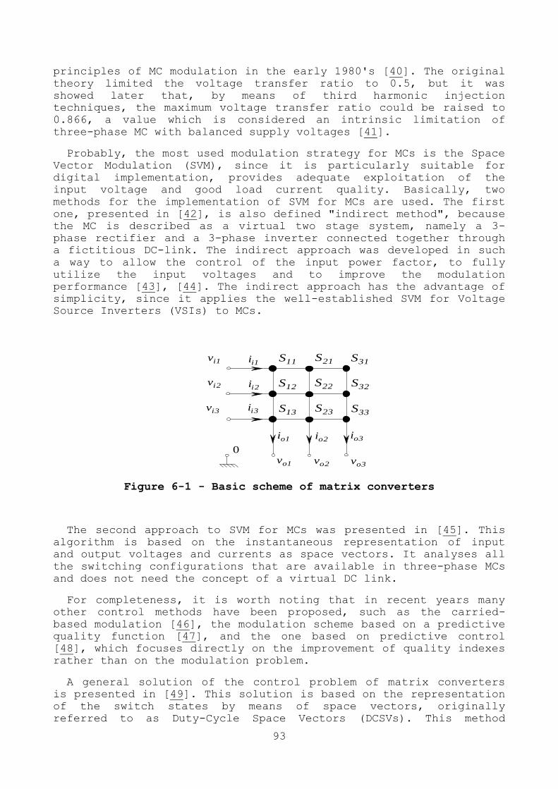
93
principles of MC modulation in the early 1980's [40]. The original
theory limited the voltage transfer ratio to 0.5, but it was
showed later that, by means of third harmonic injection
techniques, the maximum voltage transfer ratio could be raised to
0.866, a value which is considered an intrinsic limitation of
three-phase MC with balanced supply voltages [41].
Probably, the most used modulation strategy for MCs is the Space
Vector Modulation (SVM), since it is particularly suitable for
digital implementation, provides adequate exploitation of the
input voltage and good load current quality. Basically, two
methods for the implementation of SVM for MCs are used. The first
one, presented in [42], is also defined "indirect method", because
the MC is described as a virtual two stage system, namely a 3-
phase rectifier and a 3-phase inverter connected together through
a fictitious DC-link. The indirect approach was developed in such
a way to allow the control of the input power factor, to fully
utilize the input voltages and to improve the modulation
performance [43], [44]. The indirect approach has the advantage of
simplicity, since it applies the well-established SVM for Voltage
Source Inverters (VSIs) to MCs.
3ii
0
3oi
2ii
3iv
1oi 2oi
1ii
3ov
2iv
33S
11m
1ov 2ov
1iv 11S
11m
12S
11m
13S
11m
21S
11m
22S
11m
23S
11m
31S
11m
32S
11m
Figure 6-1 - Basic scheme of matrix converters
The second approach to SVM for MCs was presented in [45]. This
algorithm is based on the instantaneous representation of input
and output voltages and currents as space vectors. It analyses all
the switching configurations that are available in three-phase MCs
and does not need the concept of a virtual DC link.
For completeness, it is worth noting that in recent years many
other control methods have been proposed, such as the carried-
based modulation [46], the modulation scheme based on a predictive
quality function [47], and the one based on predictive control
[48], which focuses directly on the improvement of quality indexes
rather than on the modulation problem.
A general solution of the control problem of matrix converters
is presented in [49]. This solution is based on the representation
of the switch states by means of space vectors, originally
referred to as Duty-Cycle Space Vectors (DCSVs). This method
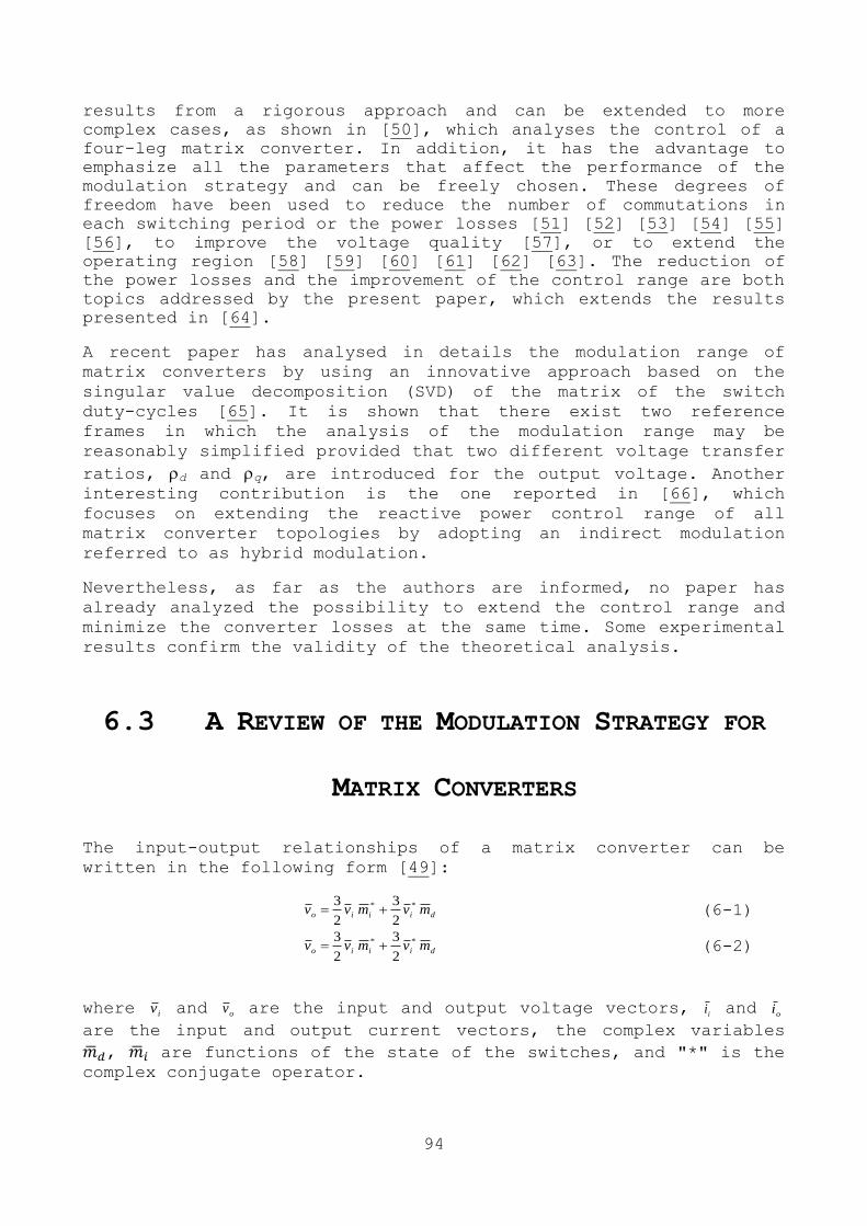
94
results from a rigorous approach and can be extended to more
complex cases, as shown in [50], which analyses the control of a
four-leg matrix converter. In addition, it has the advantage to
emphasize all the parameters that affect the performance of the
modulation strategy and can be freely chosen. These degrees of
freedom have been used to reduce the number of commutations in
each switching period or the power losses [51] [52] [53] [54] [55]
[56], to improve the voltage quality [57], or to extend the
operating region [58] [59] [60] [61] [62] [63]. The reduction of
the power losses and the improvement of the control range are both
topics addressed by the present paper, which extends the results
presented in [64].
A recent paper has analysed in details the modulation range of
matrix converters by using an innovative approach based on the
singular value decomposition (SVD) of the matrix of the switch
duty-cycles [65]. It is shown that there exist two reference
frames in which the analysis of the modulation range may be
reasonably simplified provided that two different voltage transfer
ratios, d and q, are introduced for the output voltage. Another interesting contribution is the one reported in [66], which
focuses on extending the reactive power control range of all
matrix converter topologies by adopting an indirect modulation
referred to as hybrid modulation.
Nevertheless, as far as the authors are informed, no paper has
already analyzed the possibility to extend the control range and
minimize the converter losses at the same time. Some experimental
results confirm the validity of the theoretical analysis.
6.3 A REVIEW OF THE MODULATION STRATEGY FOR
MATRIX CONVERTERS
The input-output relationships of a matrix converter can be
written in the following form [49]:
diiio mvmvv **
2
3
2
3 (6-1)
diiio mvmvv **
2
3
2
3
(6-2)
where iv and ov are the input and output voltage vectors, ii and oi
are the input and output current vectors, the complex variables
, are functions of the state of the switches, and "*" is the
complex conjugate operator.

95
If the desired phase angle of the input current space vector is
denoted by the unity vector ref , and
refov ,is the desired output
voltage vector, it is possible to demonstrate that dm and im have
the following expressions:
**
,
3 oirefi
refrefo
divv
vm
(6-3)
oirefi
refrefo
iivv
vm
*
*
,
3
(6-4)
where is a real number, and "·" is the dot-product operator, defined as the real part of the product between the first operand
and the complex conjugate of the second.
Once
, are known, it possible to calculate the following
variables, usually known in literature as "Duty-Cycle Space
Vectors":
0
)1(3
2)1(
3
2
mememmk
i
k
dk
(k=1,2,3) (6-5)
where 0m is a complex variable, usually referred to as "zero
sequence component", that can be freely chosen.
The importance of 1m , 2m and 3m is in that they allow an immediate
calculation of the switch duty-cycles. In fact, the duty-cycle khm ,
of the switch Sh,k of the converter in Fig. 1 can be determined as
follows:
13
2
,3
1
kj
hkh emm (h, k =1,2,3). (6-6)
The quantities and yield three degrees of freedom that can be
used to define any modulation strategy. The general solution given
in (3)-(6) includes all the known modulation strategies as
particular cases.
Substituting (5) in (6) leads to a very compact expression of the
duty-cycles,
khkkh Amm ,,0, (6-7)
where the quantities m0,k and Ah,k are scalar quantities defined as
follows:
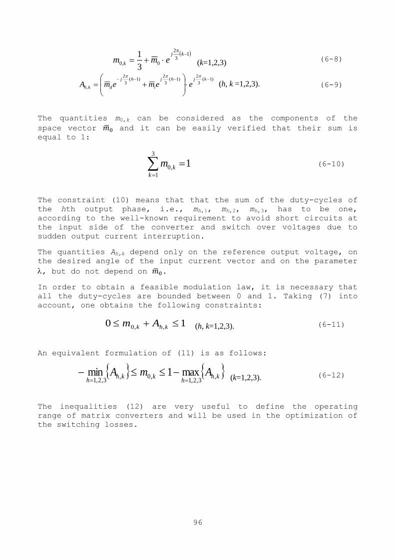
96
13
2
0,03
1
kj
k emm (k=1,2,3) (6-8)
)1(3
2)1(
3
2)1(
3
2
,
kjhj
i
hj
dkh eememA
(h, k =1,2,3).
(6-9)
The quantities m0,k can be considered as the components of the
space vector and it can be easily verified that their sum is
equal to 1:
13
1
,0 k
km
(6-10)
The constraint (10) means that that the sum of the duty-cycles of
the hth output phase, i.e., mh,1, mh,2, mh,3, has to be one,
according to the well-known requirement to avoid short circuits at
the input side of the converter and switch over voltages due to
sudden output current interruption.
The quantities Ah,k depend only on the reference output voltage, on
the desired angle of the input current vector and on the parameter
, but do not depend on .
In order to obtain a feasible modulation law, it is necessary that
all the duty-cycles are bounded between 0 and 1. Taking (7) into
account, one obtains the following constraints:
10 ,,0 khk Am (h, k=1,2,3). (6-11)
An equivalent formulation of (11) is as follows:
khh
kkhh
AmA ,3,2,1
,0,3,2,1
max1min
(k=1,2,3). (6-12)
The inequalities (12) are very useful to define the operating
range of matrix converters and will be used in the optimization of
the switching losses.
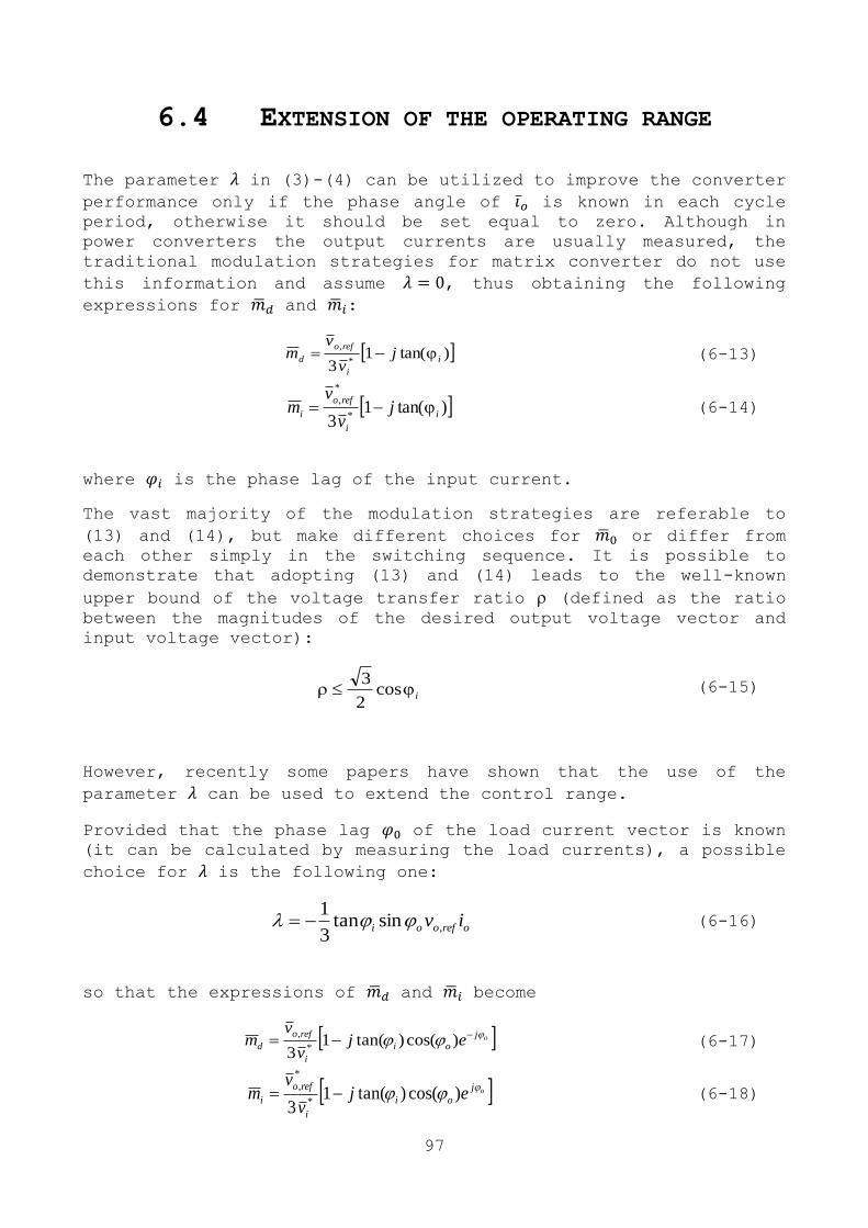
97
6.4 EXTENSION OF THE OPERATING RANGE
The parameter in (3)-(4) can be utilized to improve the converter performance only if the phase angle of is known in each cycle period, otherwise it should be set equal to zero. Although in
power converters the output currents are usually measured, the
traditional modulation strategies for matrix converter do not use
this information and assume , thus obtaining the following
expressions for and :
)tan(13 *
,
i
i
refo
d jv
vm (6-13)
)tan(13 *
*
,
i
i
refo
i jv
vm
(6-14)
where is the phase lag of the input current.
The vast majority of the modulation strategies are referable to
(13) and (14), but make different choices for or differ from
each other simply in the switching sequence. It is possible to
demonstrate that adopting (13) and (14) leads to the well-known
upper bound of the voltage transfer ratio (defined as the ratio
between the magnitudes of the desired output voltage vector and
input voltage vector):
i cos2
3 (6-15)
However, recently some papers have shown that the use of the
parameter can be used to extend the control range.
Provided that the phase lag of the load current vector is known
(it can be calculated by measuring the load currents), a possible
choice for is the following one:
orefooi iv ,sintan3
1 (6-16)
so that the expressions of and become
oj
oi
i
refo
d ejv
vm
)cos()tan(1
3 *
, (6-17)
oj
oi
i
refo
i ejv
vm
)cos()tan(13 *
*
,
(6-18)
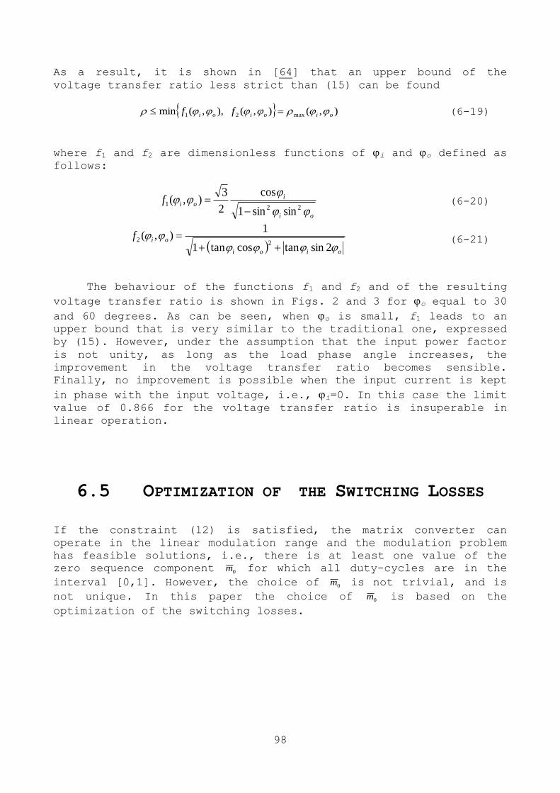
98
As a result, it is shown in [64] that an upper bound of the
voltage transfer ratio less strict than (15) can be found
),(),(),,(min max21 oioioi ff (6-19)
where f1 and f2 are dimensionless functions of i and o defined as follows:
oi
ioif
221
sinsin1
cos
2
3),(
(6-20)
oioi
oif
2sintancostan1
1),(
22
(6-21)
The behaviour of the functions f1 and f2 and of the resulting
voltage transfer ratio is shown in Figs. 2 and 3 for o equal to 30
and 60 degrees. As can be seen, when o is small, f1 leads to an upper bound that is very similar to the traditional one, expressed
by (15). However, under the assumption that the input power factor
is not unity, as long as the load phase angle increases, the
improvement in the voltage transfer ratio becomes sensible.
Finally, no improvement is possible when the input current is kept
in phase with the input voltage, i.e., i=0. In this case the limit value of 0.866 for the voltage transfer ratio is insuperable in
linear operation.
6.5 OPTIMIZATION OF THE SWITCHING LOSSES
If the constraint (12) is satisfied, the matrix converter can
operate in the linear modulation range and the modulation problem
has feasible solutions, i.e., there is at least one value of the
zero sequence component 0m for which all duty-cycles are in the
interval [0,1]. However, the choice of 0m is not trivial, and is
not unique. In this paper the choice of 0m is based on the
optimization of the switching losses.
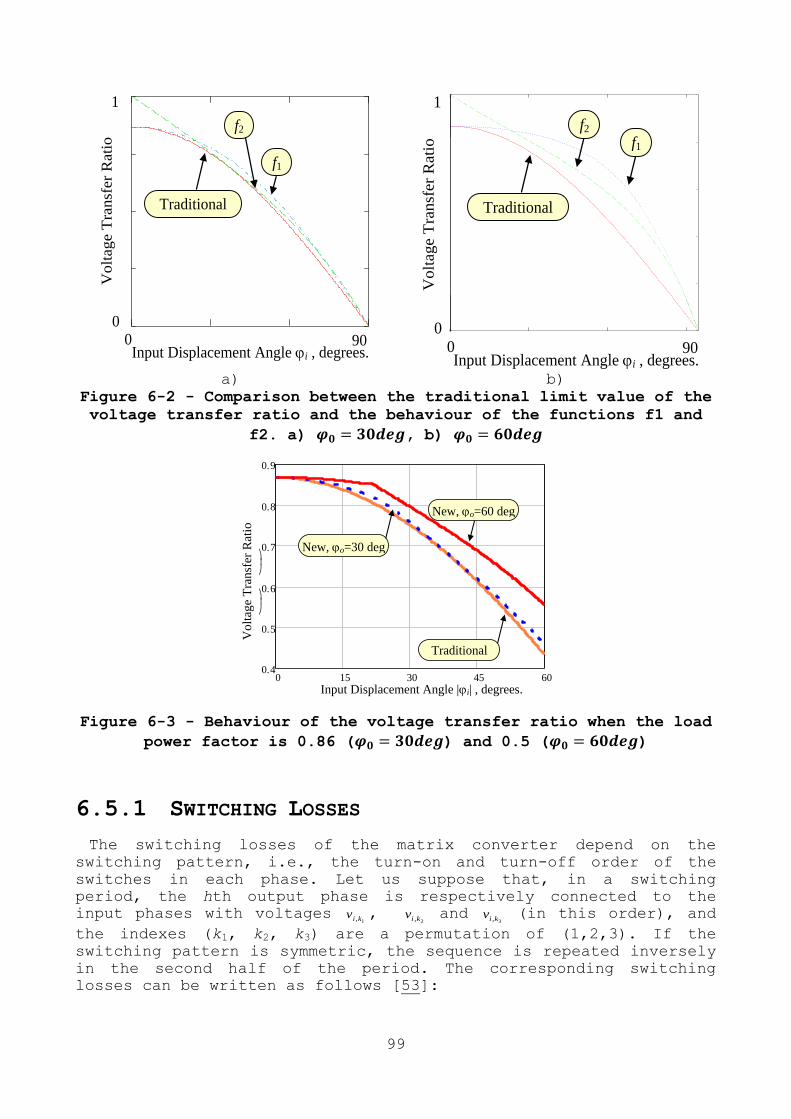
99
1
0
r1 .i 30deg
r2 .i 30deg
r4 .i 30deg
2
0 .i
1
0
f1
Traditional
0 90
f2
Input Displacement Angle i , degrees.
Volt
age T
ransf
er
Rati
o
1
0
f1
Traditional
0 90
f2
Input Displacement Angle i , degrees.
Volt
age T
ransf
er
Rati
o
0 0.5 1 1.50
0.2
0.4
0.6
0.8
1
1
0
r1 .i 60deg
r2 .i 60deg
r4 .i 60deg
2
0 .i
a) b)
Figure 6-2 - Comparison between the traditional limit value of the
voltage transfer ratio and the behaviour of the functions f1 and
f2. a) , b)
Input Displacement Angle |i| , degrees. 0 15 30 45 60
0.4
0.5
0.6
0.7
0.8
0.9
0.866
0.433
r1 .i
180 30deg
rm .i
180 30deg
rm .i
180 60deg
600 .i
Vo
ltag
e T
ran
sfer
Rat
io
Traditional
New, o=60 deg
New, o=30 deg
Figure 6-3 - Behaviour of the voltage transfer ratio when the load
power factor is 0.86 ( ) and 0.5 ( )
6.5.1 SWITCHING LOSSES
The switching losses of the matrix converter depend on the
switching pattern, i.e., the turn-on and turn-off order of the
switches in each phase. Let us suppose that, in a switching
period, the hth output phase is respectively connected to the
input phases with voltages 1,kiv ,
2,kiv and 3,kiv (in this order), and
the indexes (k1, k2, k3) are a permutation of (1,2,3). If the
switching pattern is symmetric, the sequence is repeated inversely
in the second half of the period. The corresponding switching
losses can be written as follows [53]:
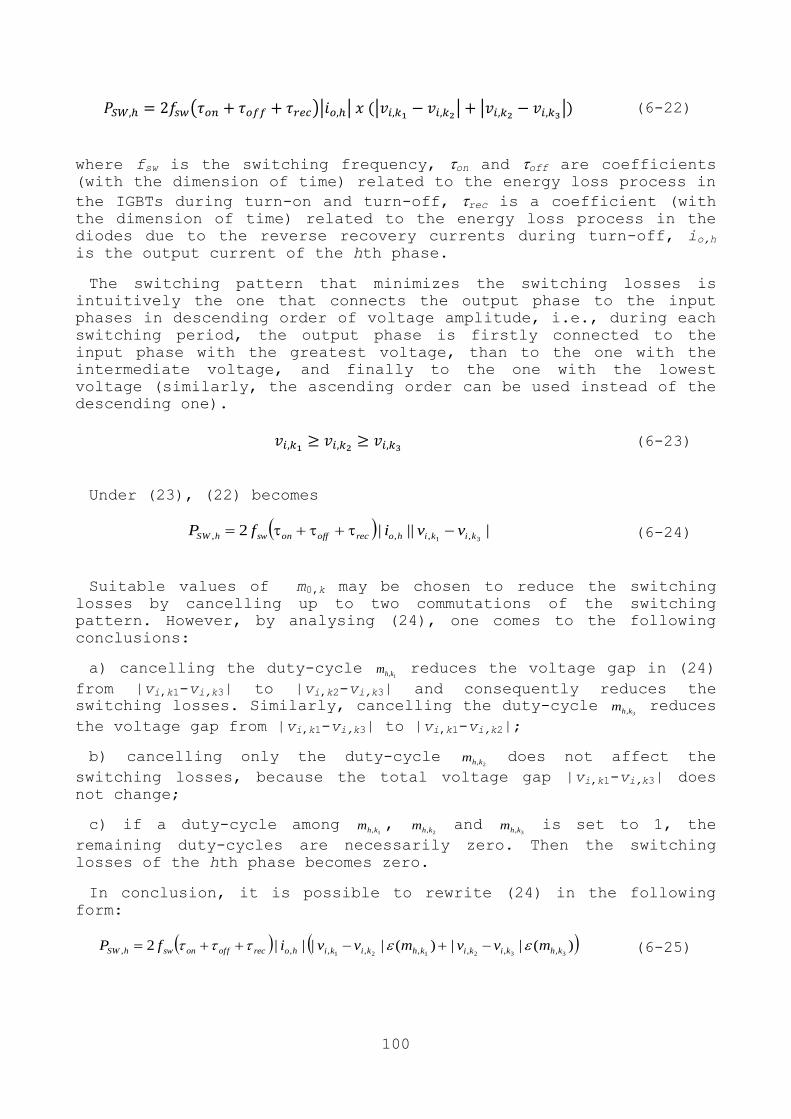
100
( )| | |
| |
| (6-22)
where fsw is the switching frequency, on and off are coefficients (with the dimension of time) related to the energy loss process in
the IGBTs during turn-on and turn-off, rec is a coefficient (with the dimension of time) related to the energy loss process in the
diodes due to the reverse recovery currents during turn-off, io,h
is the output current of the hth phase.
The switching pattern that minimizes the switching losses is
intuitively the one that connects the output phase to the input
phases in descending order of voltage amplitude, i.e., during each
switching period, the output phase is firstly connected to the
input phase with the greatest voltage, than to the one with the
intermediate voltage, and finally to the one with the lowest
voltage (similarly, the ascending order can be used instead of the
descending one).
(6-23)
Under (23), (22) becomes
||||231 ,,,, kikihorecoffonswhSW vvifP (6-24)
Suitable values of m0,k may be chosen to reduce the switching
losses by cancelling up to two commutations of the switching
pattern. However, by analysing (24), one comes to the following
conclusions:
a) cancelling the duty-cycle 1,khm reduces the voltage gap in (24)
from |vi,k1-vi,k3| to |vi,k2-vi,k3| and consequently reduces the
switching losses. Similarly, cancelling the duty-cycle 3,khm reduces
the voltage gap from |vi,k1-vi,k3| to |vi,k1-vi,k2|;
b) cancelling only the duty-cycle 2,khm does not affect the
switching losses, because the total voltage gap |vi,k1-vi,k3| does
not change;
c) if a duty-cycle among 1,khm ,
2,khm and 3,khm is set to 1, the
remaining duty-cycles are necessarily zero. Then the switching
losses of the hth phase becomes zero.
In conclusion, it is possible to rewrite (24) in the following
form:
)(||||2121 ,,,,, khkikihorecoffonswhSW mvvifP )(||
332 ,,, khkiki mvv (6-25)
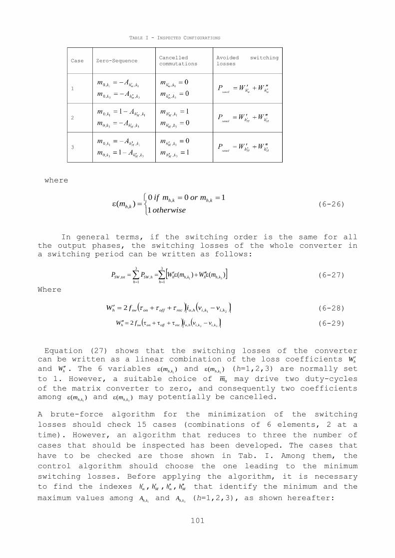
101
where
otherwise
mormifm
khkh
kh1
100)(
,,
, (6-26)
In general terms, if the switching order is the same for all
the output phases, the switching losses of the whole converter in
a switching period can be written as follows:
3
1
,,
3
1
,, )()(31
h
khhkhh
h
hSWtotSW mWmWPP (6-27)
Where
21 ,,,2 kikihorecoffonswh vvifW (6-28)
32 ,,,2 kikihorecoffonswh vvifW
(6-29)
Equation (27) shows that the switching losses of the converter
can be written as a linear combination of the loss coefficients hW
and hW . The 6 variables )(1,khm and )(
3,khm (h=1,2,3) are normally set
to 1. However, a suitable choice of 0m may drive two duty-cycles
of the matrix converter to zero, and consequently two coefficients
among )(1,khm and )(
3,khm may potentially be cancelled.
A brute-force algorithm for the minimization of the switching
losses should check 15 cases (combinations of 6 elements, 2 at a
time). However, an algorithm that reduces to three the number of
cases that should be inspected has been developed. The cases that
have to be checked are those shown in Tab. I. Among them, the
control algorithm should choose the one leading to the minimum
switching losses. Before applying the algorithm, it is necessary
to find the indexes mh , Mh , mh , Mh that identify the minimum and the
maximum values among 1,khA and
3,khA (h=1,2,3), as shown hereafter:
TABLE I - INSPECTED CONFIGURATIONS
Case Zero-Sequence Cancelled
commutations
Avoided switching
losses
1
2
3
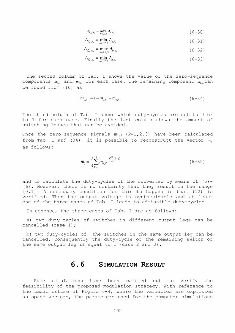
102
11 ,3,2,1
, max khh
kh AAM (6-30)
11 ,3,2,1
, min khh
kh AAm
(6-31)
33 ,3,2,1
, max khh
kh AAM
(6-32)
33 ,3,2,1
, min khh
kh AAm
(6-33)
The second column of Tab. I shows the value of the zero-sequence
components 1,0 km and
3,0 km for each case. The remaining component 2,0 km can
be found from (10) as
212 ,0,0,0 1 kkk mmm (6-34)
The third column of Tab. I shows which duty-cycles are set to 0 or
to 1 for each case. Finally the last column shows the amount of
switching losses that can be avoided.
Once the zero-sequence signals m0,k (k=1,2,3) have been calculated
from Tab. I and (34), it is possible to reconstruct the vector 0m
as follows:
3
1
13
2
,003
2
k
kj
kemm
(6-35)
and to calculate the duty-cycles of the converter by means of (5)-
(6). However, there is no certainty that they result in the range
[0,1]. A necessary condition for this to happen is that (12) is
verified. Then the output voltage is synthesizable and at least
one of the three cases of Tab. I leads to admissible duty-cycles.
In essence, the three cases of Tab. I are as follows:
a) two duty-cycles of switches in different output legs can be
cancelled (case 1);
b) two duty-cycles of the switches in the same output leg can be
cancelled. Consequently the duty-cycle of the remaining switch of
the same output leg is equal to 1 (case 2 and 3).
6.6 SIMULATION RESULT
Some simulations have been carried out to verify the
feasibility of the proposed modulation strategy. With reference to
the basic scheme of Figure 6-4, where the variables are expressed
as space vectors, the parameters used for the computer simulations

103
are shown in Table II. The switching frequency is 8 kHz,
Figure 6-5 shows the behaviour of the matrix converter when
the output delay angle is 60 degrees, the input delay angle is 30 degrees and the voltage transfer ratio is 0.79 (which cannot be
achieved by the conventional modulation strategies). The bottom
traces in both figures show the waveforms of the duty-cycles m1,1,
m1,2 and m1,3. As can be seen, the output and input currents are
sinusoidal, although the duty-cycles are discontinuous in an
unpredictable way. Each time one of the nine duty-cycles is zero,
it means that the corresponding switch does not commutate. If it
is one, the corresponding switch stays turned on during the entire
switching period.
The comparison of the modulation strategies in terms of
switching losses has been carried out by using PLECS. The
evaluation of the power losses has been done under the assumption
that the power module FM35R12KE3, produced by Infineon-Eupec, is
used. Figure 6-6 shows the turn-on and turn-off energy loss of an
IGBT and the recovery energy loss of a diode when the voltage
applied to the switches is 600 V and the junction temperature is
125°C, whereas Figure 6-7 shows the output characteristic of an
IGBT and a diode.
Figure 6-8 shows the power losses of all the modulation
strategies, divided into switching and total losses when the
voltage transfer ratio is the maximum according to (15). It turns
out that the proposed modulation strategy shows losses which are
considerable lower than the SVM with three zero vectors (SVM3z),
the SVM with two zero vectors (SVM2z), and the SVM with one zero
vector (SVM1z). SVM2z uses the zero vectors that are not in the
middle of the double-sided switching pattern, whereas SVM1z uses
the zero vectors at the beginning and at the end of the double-
sided switching pattern.
In the examined operating conditions the reduction in the
switching losses varies from 10% to 32% in comparison to those of
SVM1z.
Matrix
converter
Rs Ls Rl Ll
Non ideal voltage supply Input filter Load
Digital
controller
Lf
Cf
ii
iv ov oisv
ivoi
id mm ,
Figure 6-4 – Schematic diagram of the system based on matrix
converter
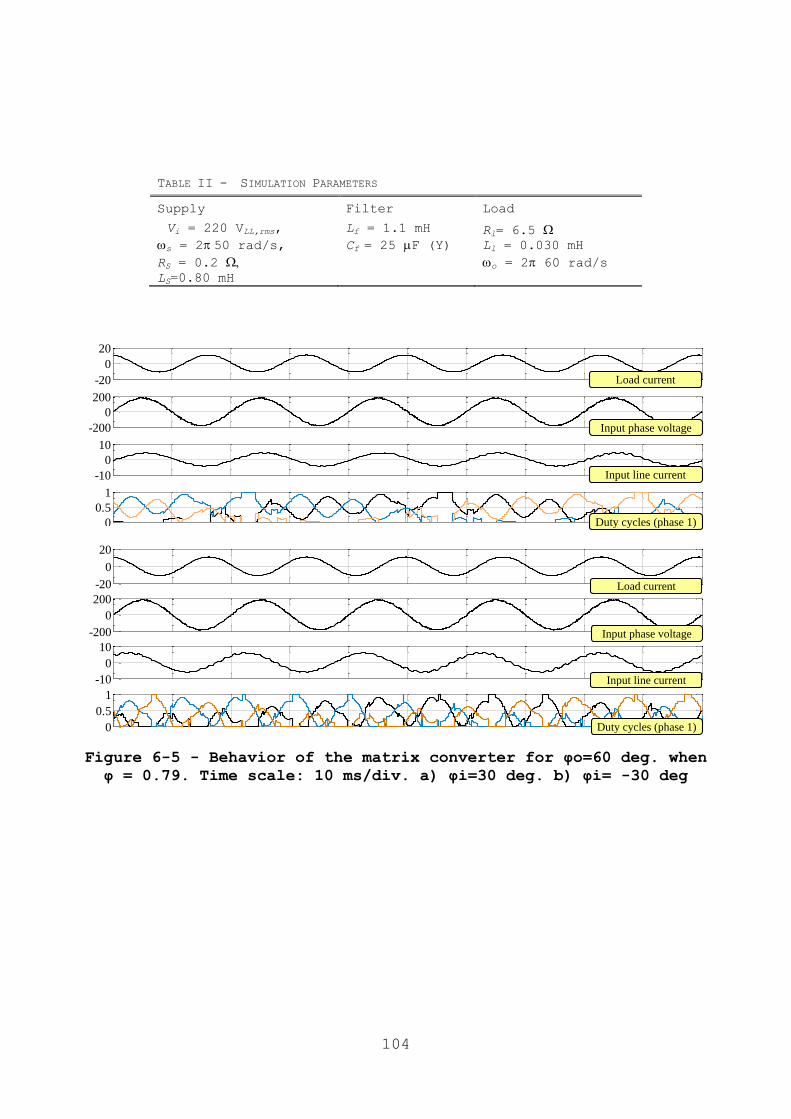
104
-20
0
20
-200
0
200
-10
0
10
0
0.5
1
Input line current
Input phase voltage
Load current
Duty cycles (phase 1)
-20
0
20
-200
0
200
-10
0
10
0
0.5
1
Input line current
Input phase voltage
Load current
Duty cycles (phase 1)
Figure 6-5 - Behavior of the matrix converter for φo=60 deg. when
φ = 0.79. Time scale: 10 ms/div. a) φi=30 deg. b) φi= -30 deg
TABLE II - SIMULATION PARAMETERS
Supply Filter Load
Vi = 220 VLL,rms,
s = 250 rad/s,
RS = 0.2
LS=0.80 mH
Lf = 1.1 mH
Cf = 25 F (Y) Rl= 6.5 Ll = 0.030 mH
o = 2 60 rad/s

105
0
1
2
3
4
5
6
7
8
9
0 20 40 60 80
Sw
itch
ing e
ner
gy l
oss
(m
J)
Forward current (A)
IGBT Turn on
IGBT Turn off
Diode recovery
losses
Figure 6-6 - Switching losses of an IGBT and a diode of the model
used for the computer simulations, when the final voltage after
turn-on and the initial voltage before turn-off is 600 V, and the
junction temperature is 125°C
0
15
30
45
60
0 0,5 1 1,5 2
Fo
rwo
rd c
urr
ent
(A)
Forward voltage (V)
Diode
IGBT
Figure 6-7 - Output characteristic of an IGBT and a diode of the
model used for the computer simulations, when the junction
temperature is 125°C
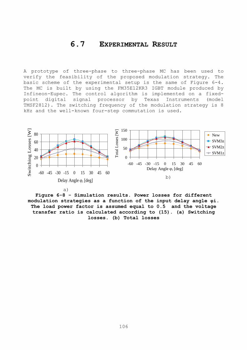
106
6.7 EXPERIMENTAL RESULT
A prototype of three-phase to three-phase MC has been used to
verify the feasibility of the proposed modulation strategy. The
basic scheme of the experimental setup is the same of Figure 6-4.
The MC is built by using the FM35E12KR3 IGBT module produced by
Infineon-Eupec. The control algorithm is implemented on a fixed-
point digital signal processor by Texas Instruments (model
TMSF2812). The switching frequency of the modulation strategy is 8
kHz and the well-known four-step commutation is used.
Delay Angle i [deg]
0
20
40
60
80
-60 -45 -30 -15 0 15 30 45 60
Sw
itch
ing
Lo
sses [
W].
New
SVM3z
SVM2z
SVM1z
a)
0
50
100
150
-60 -45 -30 -15 0 15 30 45 60
To
tal
Lo
sses
[W]
New
SVM3z
SVM2z
SVM1z
Delay Angle i [deg]
b)
Figure 6-8 - Simulation results. Power losses for different
modulation strategies as a function of the input delay angle φi.
The load power factor is assumed equal to 0.5 and the voltage
transfer ratio is calculated according to (15). (a) Switching
losses. (b) Total losses
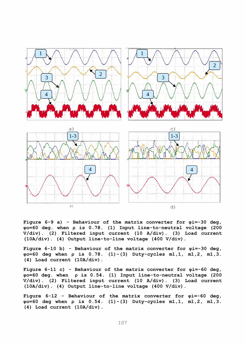
107
4
2
1
3
4
2
1
3
a) c)
1-3
4
1-3
4
b) d)
Figure 6-9 a) - Behaviour of the matrix converter for φi=-30 deg,
φo=60 deg. when ρ is 0.78. (1) Input line-to-neutral voltage (200
V/div). (2) Filtered input current (10 A/div). (3) Load current
(10A/div). (4) Output line-to-line voltage (400 V/div).
Figure 6-10 b) - Behaviour of the matrix converter for φi=-30 deg,
φo=60 deg when ρ is 0.78. (1)-(3) Duty-cycles m1,1, m1,2, m1,3.
(4) Load current (10A/div).
Figure 6-11 c) - Behaviour of the matrix converter for φi=-60 deg,
φo=60 deg. when ρ is 0.54. (1) Input line-to-neutral voltage (200
V/div). (2) Filtered input current (10 A/div). (3) Load current
(10A/div). (4) Output line-to-line voltage (400 V/div).
Figure 6-12 - Behaviour of the matrix converter for φi=-60 deg,
φo=60 deg when ρ is 0.54. (1)-(3) Duty-cycles m1,1, m1,2, m1,3.
(4) Load current (10A/div).

108
Figure 6-9 and Figure 6-10 show the behaviour of the matrix
converter when the input displacement angle is -30° (the converter
absorbs capacitive reactive power and acts as a power factor
corrector) and the load delay angle is 60°, corresponding to a
fundamental input power factor of 0.86 (capacitive) and a
fundamental output power factor of 0.5. The voltage transfer ratio
in Figs. 9 and 10 has been increased up to 0.78, which is greater
than the limit given by (15), i.e., 0.74.
Figure 6-11 and Figure 6-12 show the behaviour of the
converter in the same operating conditions, except for the input
displacement angle, which is equal to -60°. The voltage transfer
ratio of Figs. 11 and 12 is equal to 0.54, which is 25% greater
than the traditional limit, 0.43.
In all figures, the behavior of the converter is satisfactory.
The input and output quantities are almost sinusoidal and the
duty-cycles are clamped in the interval [0,1]. As can be seen, the
duty-cycles are frequently equal to 0 or to 1, which confirms the
cancellation of some commutations.
6.8 CONCLUSION
In this chapter a modulation strategy that simultaneously improves
the control range of matrix converter and reduces the switching
losses is proposed.
The theoretical analysis shows that the zero-sequence component
can be used to minimize the power losses, whereas the remaining
degree of freedom can be used to extend the control range of the converter.
Compared to the traditional SVM, the proposed modulation strategy
is able to obtain higher voltage transfer ratios under the
assumption that the desired power factor at the input and at the
output of the converter is not unity.
As a result, the switching losses can be sensibly reduced compared
to traditional modulation strategies. The simulation results,
performed under the assumption that the load power factor is 0.5,
show reductions in the switching losses up to 32% compared to
SVM1z.

109

110
Chapter 7
MODULATION STRATEGY WITH MINIMUM
SWITCHING LOSSES FOR THREE-PHASE
AC-DC MATRIX CONVERTERS
7.1 ABSTRACT
Passive three-phase rectifier circuits are very popular for ac-dc
power conversion. However, they do not have the capability to
reverse the power flow, which is demanded by some recent potential
smart-grid applications, such as vehicle-to-grid (V2G) power
transfer.
As an alternative, this paper analyses the behaviour of three-
phase ac-dc matrix converters. Among the modulation strategies
that minimize the switching losses, the one leading to the minimum
output current ripple is chosen. The behaviour of this modulation
strategy is experimentally tested.
7.2 INTRODUCTION
Interconnection of power electronics to the grid has been
performed for a long time by using passive three-phase rectifier
circuits in combination with inductors located either on the ac or
on the dc-side. These rectifier circuits are simple, show a high
efficiency and are very robust, but result in a total harmonic
distortion of the input currents (THDi) of typically 30–50% and
show a considerably small power factor. In addition, they cannot
allow a bidirectional power flow, and therefore they are not
suitable for emerging applications, such as vehicle-to-grid (V2G)
power exchange or smart grid applications [67] [68].
Due to upcoming standards containing rigorous input current
harmonic limits, in many cases passive rectifiers cannot be used
any more. Three-phase pulse width-modulated (PWM) voltage- and
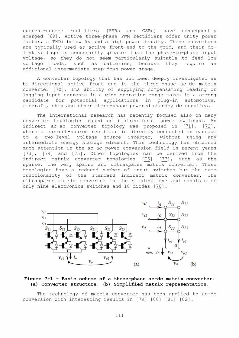
111
current-source rectifiers (VSRs and CSRs) have consequently
emerged [69]. Active three-phase PWM rectifiers offer unity power
factor, a THDi below 5% and a high power density. These converters
are typically used as active front-end to the grid, and their dc-
link voltage is necessarily greater than the phase-to-phase input
voltage, so they do not seem particularly suitable to feed low
voltage loads, such as batteries, because they require an
additional intermediate step-down power stage.
A converter topology that has not been deeply investigated as
bi-directional active front end is the three-phase ac-dc matrix
converter [70]. Its ability of supplying compensating leading or
lagging input currents in a wide operating range makes it a strong
candidate for potential applications in plug-in automotive,
aircraft, ship and other three-phase powered standby dc supplies.
The international research has recently focused also on many
converter topologies based on bidirectional power switches. An
indirect ac–ac converter topology was proposed in [71], [72],
where a current-source rectifier is directly connected in cascade
to a two-level voltage source inverter, without using any
intermediate energy storage element. This technology has obtained
much attention in the ac–ac power conversion field in recent years
[73], [74] and [75]. Other topologies can be derived from the
indirect matrix converter topologies [76] [77], such as the
sparse, the very sparse and ultrasparse matrix converter. These
topologies have a reduced number of input switches but the same
functionality of the standard indirect matrix converter. The
ultrasparse matrix converter is the simplest one and consists of
only nine electronics switches and 18 diodes [78].
Figure 7-1 - Basic scheme of a three-phase ac-dc matrix converter.
(a) Converter structure. (b) Simplified matrix representation.
The technology of matrix converter has been applied to ac-dc
conversion with interesting results in [79] [80] [81] [82].
112
In this paper, the three-phase ac-dc direct matrix converter
topology is analysed and the modulation strategies leading to the
minimum converter losses are found. Finally, among them, the one
producing the minimum output current ripple is identified as the
best choice. This work can be considered as the prosecution of
similar analyses carried out for direct, indirect and sparse
matrix converters [76], [83] [84] [85] [86] [87] [88].
The feasibility and the performance of the proposed modulation
strategy are confirmed by numerical simulation and experimental
results.
7.3 MODULATION STRATEGY FOR AC/DC MATRIX
CONVERTERS
The performance of matrix converters is strictly related to
the adopted modulation strategy. Several modulation strategies,
based on different mathematical approaches, have been presented in
the past for traditional direct three-phase MCs [89]. Each of them
shows different features in terms of number of switch commutations
in a switching period or degree of utilization of the input
voltage. Probably, the most used modulation strategy for MCs is
the Space Vector Modulation (SVM), since it is particular suitable
for digital implementation, provides adequate exploitation of the
input voltage and good load current quality [45]. A general
solution of the control problem of three-phase direct ac/ac matrix
converters is presented in [49]. This solution is based on the
representation of the switch states by means of space vectors,
originally referred to as Duty-Cycle Space Vectors (DCSVs). This
method results from a rigorous approach and it has the advantage
to emphasize all the parameters that affect the performance of the
modulation strategy and can be freely chosen. In addition it can
be extended to more complex cases, as shown in [90], which
analyses the control of a four-leg matrix converter. In the
following, the same method will be adapted for the analysis of
ac/dc matrix converters.
7.3.1 INPUT OUTPUT EQUATIONS OF THE AC/DC MATRIX
CONVERTERS
With reference to Fig. 1, the expression of the output voltage vo
is as follows:

113
∑( )
(7-1)
where vi,k (k=1,2,3) are the input voltages and h k m , (h=1,2 and
k=1,2,3) are the duty-cycles of the switches Sh,k.
Since the converter does not include elements that can store
energy, if the converter power losses are neglected, the input
power is equal to the output power, i.e.,
∑
∑( )
(7-2)
where io is the output current.
Equation (2) is verified for any value of vi,k, so it is possible
to conclude that the input currents are
( ) (7-3)
The duty-cycles m1,k and m2,k have to satisfy the usual constraints
∑
(7-4)
which prevent short-circuits and over-voltages.
7.3.2 INPUT-OUTPUT EQUATIONS IN TERMS OF SPACE
VECTORS
The input equation voltages and current can be written in terms of
space vectors and whose components are
(7-5)
(7-6)
where ―.‖ Is the dot product, defined as the real part of the
product between the first operand and the complex conjugate of the
second operand, and
(7-7)
The state of the converter legs can be represented by two complex
numbers m1, m2 defined as follows:
∑
(7-8)
Replacing (5) and (6) in (1) and (3), and considering (8), the
input-output equations of a three-phase ac-dc matrix converter can
be written in terms of m1 and m2 as follows:
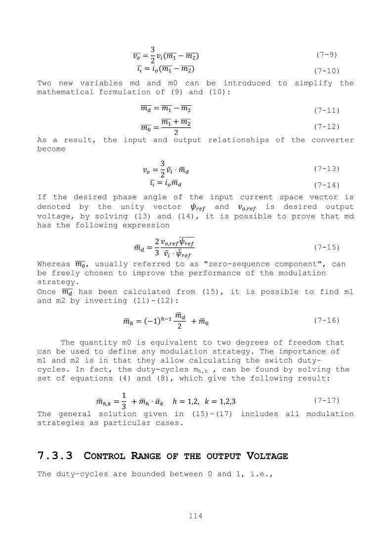
114
(7-9)
(7-10)
Two new variables md and m0 can be introduced to simplify the
mathematical formulation of (9) and (10):
(7-11)
(7-12)
As a result, the input and output relationships of the converter
become
(7-13)
(7-14)
If the desired phase angle of the input current space vector is
denoted by the unity vector and is desired output
voltage, by solving (13) and (14), it is possible to prove that md
has the following expression
(7-15)
Whereas , usually referred to as "zero-sequence component", can be freely chosen to improve the performance of the modulation
strategy.
Once has been calculated from (15), it is possible to find m1 and m2 by inverting (11)-(12):
(7-16)
The quantity m0 is equivalent to two degrees of freedom that
can be used to define any modulation strategy. The importance of
m1 and m2 is in that they allow calculating the switch duty-
cycles. In fact, the duty-cycles mh,k , can be found by solving the
set of equations (4) and (8), which give the following result:
(7-17)
The general solution given in (15)-(17) includes all modulation
strategies as particular cases.
7.3.3 CONTROL RANGE OF THE OUTPUT VOLTAGE
The duty-cycles are bounded between 0 and 1, i.e.,
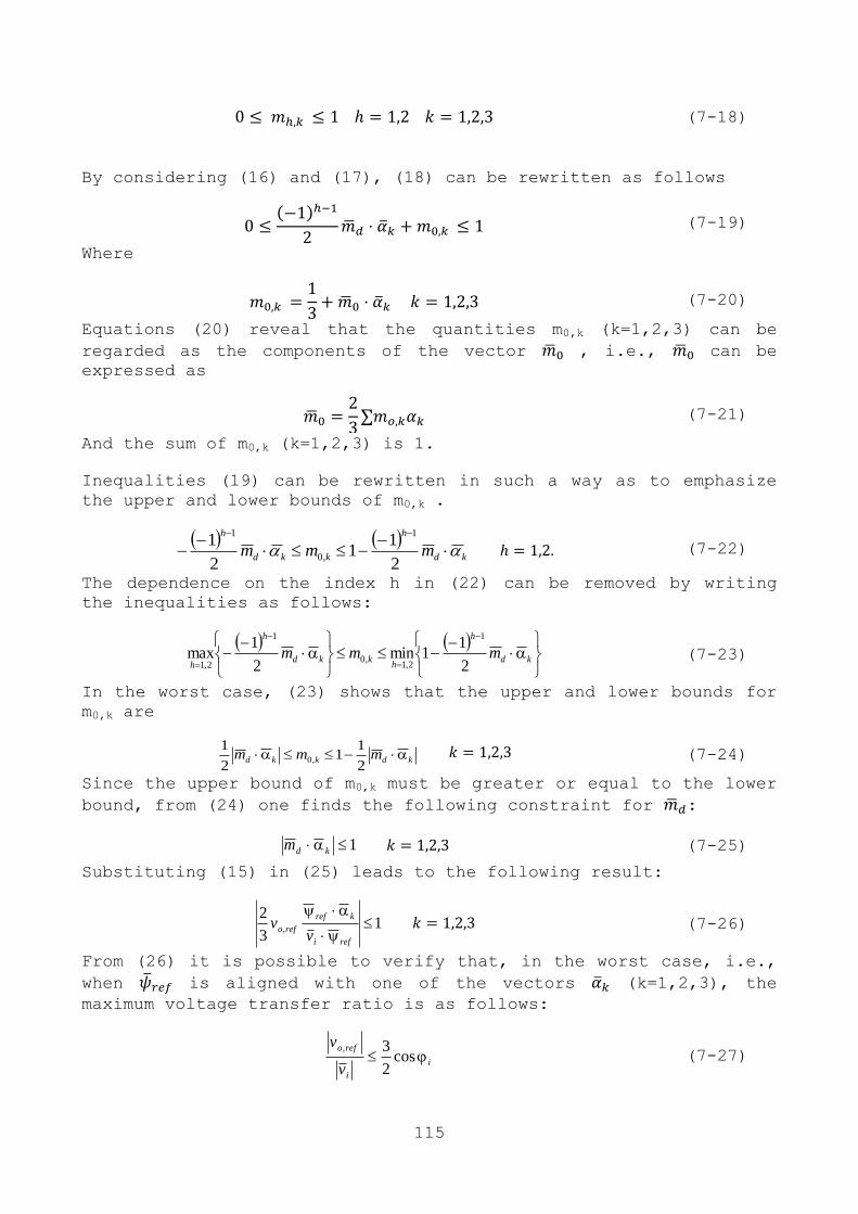
115
(7-18)
By considering (16) and (17), (18) can be rewritten as follows
(7-19)
Where
(7-20)
Equations (20) reveal that the quantities m0,k (k=1,2,3) can be
regarded as the components of the vector , i.e., can be
expressed as
(7-21)
And the sum of m0,k (k=1,2,3) is 1.
Inequalities (19) can be rewritten in such a way as to emphasize
the upper and lower bounds of m0,k .
kd
h
kkd
h
mmm
2
11
2
11
,0
1
(7-22)
The dependence on the index h in (22) can be removed by writing
the inequalities as follows:
kd
h
hkkd
h
hmmm
2
11min
2
1max
1
2,1,0
1
2,1 (7-23)
In the worst case, (23) shows that the upper and lower bounds for
m0,k are
kdkkd mmm 2
11
2
1,0
(7-24)
Since the upper bound of m0,k must be greater or equal to the lower
bound, from (24) one finds the following constraint for :
1 kdm (7-25)
Substituting (15) in (25) leads to the following result:
13
2,
refi
kref
refov
v (7-26)
From (26) it is possible to verify that, in the worst case, i.e.,
when is aligned with one of the vectors (k=1,2,3), the
maximum voltage transfer ratio is as follows:
i
i
refo
v
v cos
2
3, (7-27)

116
where i is the displacement angle between the input voltage vector
and the input current vector.
If the constraint (27) is satisfied, the ac-dc matrix converter
can operate in the linear modulation range and the modulation
problem has feasible solutions. This means that there is at least
one value of the zero sequence component that makes all duty-
cycles remain in the interval [0,1]. The optimal choice of is
not trivial and is discussed in the next section.
7.4 IMPROVEMENT IN THE SWITCHING LOSSES AND
OUTPUT CURRENT RIPPLE
7.4.1 GENERAL EXPRESSION OF THE SWITCHING LOSSES
The values of the duty-cycles (17) of the switches are not
sufficient to univocally identify a modulation strategy, because
it is still possible to choose different switching sequences,
i.e., different turn-on and turn-off ordering of the switches.
In this paper it is assumed that the same switching pattern is
used for both output phases and that during a switching period
each output phase is connected to the input phases in a specific
order, depending on the amplitude of the input voltages. Each
output phase is firstly connected to the input phase with the
greatest voltage, than to the one with the intermediate voltage,
and finally to the one with the lowest voltage (if the switching
pattern is symmetric, the sequence is repeated in reverse order in
the second half of the period). It is known that this switching
pattern is the one that minimizes the switching losses of the
converter, although it may be slightly detrimental for the input
and output current quality. Let us suppose that the indices of the
input voltages in descending order is given by the triplet (k1, k2,
k3),
(7-28)
then, if the four-step commutation is used, the switching losses
of the converter in a switching period can be expressed as
follows:
2
1
,,,,, 32212
h
hkikihkikiorecoffonswtotSW vvvvifP (7-29)
where fsw is the switching frequency, on and off are coefficients (with the dimension of time) related to the energy loss process in
the IGBTs during turn-on and turn-off, rec is a coefficient (with

117
the dimension of time) related to the energy loss process in the
diodes due to the reverse recovery currents during turn-off. The
coefficient h is equal to 1 if the hth output voltage commutates
between the maximum and the intermediate input voltage in the
switching period, or 0 if this transition does not exist.
Similarly, the coefficient h is 1 if the hth output voltage
commutates between the intermediate and the minimum input voltage
in the switching period. If the modulation strategy does not
reduce the switching losses, the four coefficients h and
h
(h=1,2) are normally equal to 1, but a suitable choice of 0m may
cancel two of them. However the previous analysis shows that, to
reduce the switching losses, it is necessary to focus on the
switches connected to input phases k1 and k3, whereas those
connected to input phase k2 are not significant.
7.4.2 OPTIMAL ZERO SEQUENCE COMPONENT FOR THE
REDUCTION OF THE SWITCHING LOSSES
It is possible to verify that there are only three values of 0m
that leads to an effective reduction in the switching losses. The
components 1,0 km ,
2,0 km and 3,0 km values can be deduced from Table I.
Let us focus on Case 1 of Table I. According to (24), the
expression
11 2
11,0 kdk mm (7-30)
is the upper bound of 1,0 km . Hence, if (30) is verified, one of the
two duty-cycles, 1,1 km or
1,2 km , increases up to 1, i.e.,
11,ˆ
khm (7-31)
where h is the index of the output phase.
Necessarily, (31) forces the other duty-cycles of the same
output leg to be zero. Consequently,
03,ˆ
khm . (7-32)
Equation (33) means that 3,0 km is equal to its lower bound, which is
33 2
1,0 kdk mm . (7-33)
The component 2,0 km can be calculated once the values of
1,0 km and
3,0 km are known.
312 ,0,0,0 1 kkk mmm . (7-34)
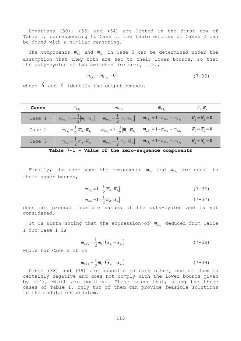
118
Equations (30), (33) and (34) are listed in the first row of
Table I, corresponding to Case 1. The table entries of Cases 2 can
be found with a similar reasoning.
The components 1,0 km and
3,0 km in Case 3 can be determined under the
assumption that they both are set to their lower bounds, so that
the duty-cycles of two switches are zero, i.e.,
031 ,
~,ˆ
khkh
mm . (7-35)
where h and h~ identify the output phases.
Table 7-1 – Value of the zero-sequence components
Finally, the case when the components 1,0 km and
3,0 km are equal to
their upper bounds,
11 2
11,0 kdk mm (7-36)
33 2
11,0 kdk mm (7-37)
does not produce feasible values of the duty-cycles and is not
considered.
It is worth noting that the expression of 2,0 km deduced from Table
I for Case 1 is
312
12,0 kkdk mm (7-38)
while for Case 2 it is
312
12,0 kkdk mm (7-39)
Since (38) and (39) are opposite to each other, one of them is
certainly negative and does not comply with the lower bounds given
by (24), which are positive. These means that, among the three
cases of Table I, only two of them can provide feasible solutions
to the modulation problem.
Cases 1,0 km
3,0 km 2,0 km
hh ,
Case 1 11 2
11,0 kdk mm
33 2
1,0 kdk mm
312 ,0,0,0 1 kkk mmm 0ˆˆ hh
Case 2 11 2
1,0 kdk mm
33 2
11,0 kdk mm
312 ,0,0,0 1 kkk mmm 0ˆˆ hh
Case 3 11 2
1,0 kdk mm
33 2
1,0 kdk mm
312 ,0,0,0 1 kkk mmm 0~ˆ hh
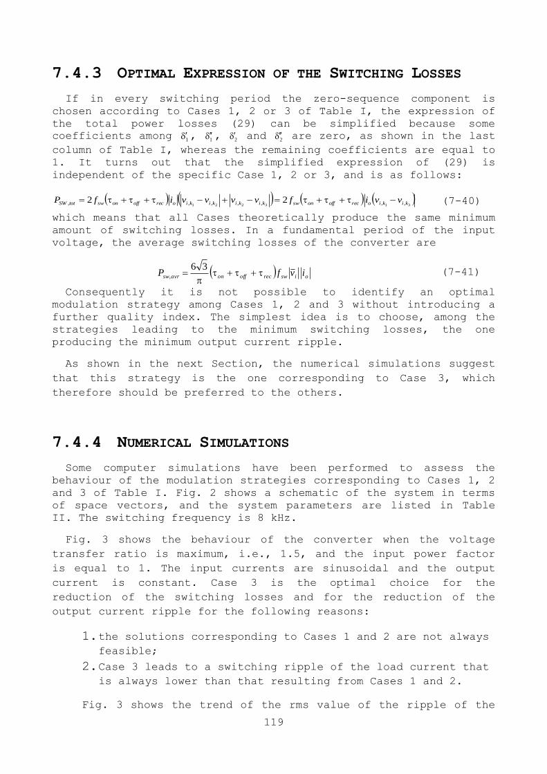
119
7.4.3 OPTIMAL EXPRESSION OF THE SWITCHING LOSSES
If in every switching period the zero-sequence component is
chosen according to Cases 1, 2 or 3 of Table I, the expression of
the total power losses (29) can be simplified because some
coefficients among 1 , 1 , 2 and 2 are zero, as shown in the last
column of Table I, whereas the remaining coefficients are equal to
1. It turns out that the simplified expression of (29) is
independent of the specific Case 1, 2 or 3, and is as follows:
313221 ,,,,,,, 22 kikiorecoffonswkikikikiorecoffonswtotSW vvifvvvvifP (7-40)
which means that all Cases theoretically produce the same minimum
amount of switching losses. In a fundamental period of the input
voltage, the average switching losses of the converter are
oiswrecoffonavrsw ivfP
36
, (7-41)
Consequently it is not possible to identify an optimal
modulation strategy among Cases 1, 2 and 3 without introducing a
further quality index. The simplest idea is to choose, among the
strategies leading to the minimum switching losses, the one
producing the minimum output current ripple.
As shown in the next Section, the numerical simulations suggest
that this strategy is the one corresponding to Case 3, which
therefore should be preferred to the others.
7.4.4 NUMERICAL SIMULATIONS
Some computer simulations have been performed to assess the
behaviour of the modulation strategies corresponding to Cases 1, 2
and 3 of Table I. Fig. 2 shows a schematic of the system in terms
of space vectors, and the system parameters are listed in Table
II. The switching frequency is 8 kHz.
Fig. 3 shows the behaviour of the converter when the voltage
transfer ratio is maximum, i.e., 1.5, and the input power factor
is equal to 1. The input currents are sinusoidal and the output
current is constant. Case 3 is the optimal choice for the
reduction of the switching losses and for the reduction of the
output current ripple for the following reasons:
1. the solutions corresponding to Cases 1 and 2 are not always feasible;
2. Case 3 leads to a switching ripple of the load current that is always lower than that resulting from Cases 1 and 2.
Fig. 3 shows the trend of the rms value of the ripple of the

120
load current for all Cases. The rms value of the current ripple is
calculated as follows:
SWT
O
SW
RMS dttiT
I0
2)(1
(7-42)
where io(t) is the load current ripple, i.e., the difference
between the actual load current and its mean value over a
switching period TSW. The current ripple io(t) is numerically
estimated by solving the following approximated differential
equation in each switching period,
refoool vtvidt
dL ,)( (7-43)
under the assumption that the current ripple is zero at the
beginning and at the end of the switching period, due to the
symmetry of the switching pattern, and vo(t) changes according to
the switching pattern resulting from Cases 1, 2 or 3.
AC-DC
Matrix
Rectifier
Rs Ls Rl Ll
Non ideal voltage supply Input filter Load
Digital
controller
0, mmd Lf
Cf
ii
iv ov oisv
Figure 7-2 - Basic scheme of AC/DC conversion system
Table 7-2 - Simulation Paramters
Supply Filter Load
As can be seen from Fig. 3, the rms value of the current ripple
corresponding to Case 3 is always the lowest one. The rms value of
the current ripple for Cases 1 and Case 2 is alternatively equal
to zero, because the corresponding duty-cycles are not admissible.
Fig. 4 shows the behaviour of the converter when the voltage
transfer ratio is 0.5. As can be seen, the conclusion remains that
Case 3 is the best choice.
Furthermore, Figs. 3 and 4 show the waveform of the duty-cycles
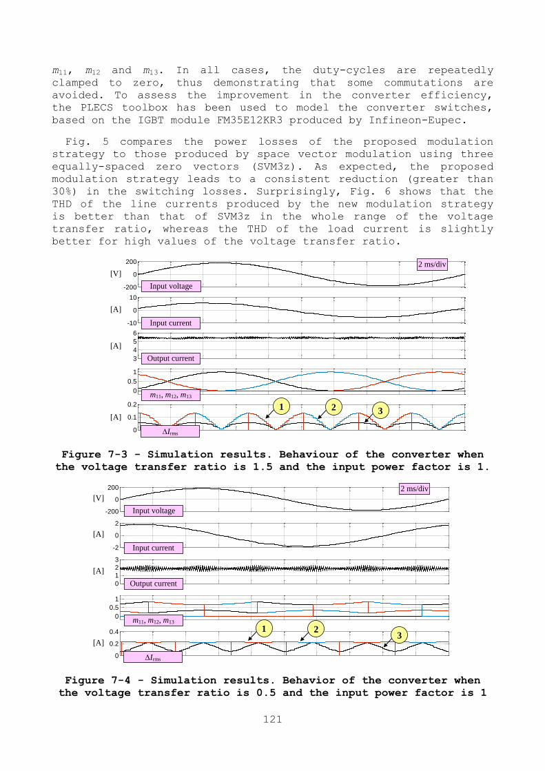
121
m11, m12 and m13. In all cases, the duty-cycles are repeatedly
clamped to zero, thus demonstrating that some commutations are
avoided. To assess the improvement in the converter efficiency,
the PLECS toolbox has been used to model the converter switches,
based on the IGBT module FM35E12KR3 produced by Infineon-Eupec.
Fig. 5 compares the power losses of the proposed modulation
strategy to those produced by space vector modulation using three
equally-spaced zero vectors (SVM3z). As expected, the proposed
modulation strategy leads to a consistent reduction (greater than
30%) in the switching losses. Surprisingly, Fig. 6 shows that the
THD of the line currents produced by the new modulation strategy
is better than that of SVM3z in the whole range of the voltage
transfer ratio, whereas the THD of the load current is slightly
better for high values of the voltage transfer ratio.
-200
0
200
-10
0
10
3
4
5
6
0
0.5
1
0
0.1
0.2
Input voltage
Input current
Output current
m11, m12, m13
[V]
[A]
[A]
[A]
2 ms/div
1 2 3
Irms
Figure 7-3 - Simulation results. Behaviour of the converter when
the voltage transfer ratio is 1.5 and the input power factor is 1.
-200
0
200
-2
0
2
0
1
2
3
0
0.5
1
0
0.2
0.4
Input voltage
Input current
Output current
m11, m12, m13
[V]
[A]
[A]
[A]
2 ms/div
1 2 3
Irms
Figure 7-4 - Simulation results. Behavior of the converter when
the voltage transfer ratio is 0.5 and the input power factor is 1

122
0
10
20
30
40
Pow
er L
oss
es [
W]
New SVM3z
Switching
Conduction
0.5 0.75 1 1.5 Voltage Transfer Ratio
Figure 7-5 - Power losses of the new
modulation strategy of the space
vector modulation with three zero
vectors (SVM3z), when the input
power factor is 1.
0
2
4
6
8
10
0.5 1 1.5
SVM3z
New
THD%
line current
THD%
load current
Voltage Transfer Ratio
TH
D%
Figure 7-6 - THD of line and
load currents for the new
modulation strategy and for
the space vector modulation
with three zero vectors
(SVM3z), when the input
power factor is 1.
ii,1
vo
vi,1
io
a)
m11
vo
m12
io
b)
Figure 7-7 - Behaviour of the matrix converter when the input
power factor is 1 and the voltage transfer ratio is 1.5. Input
voltage (200 V/div). Input current (5 A/div). Load current
(5A/div). Output voltage (200 V/div).
ii,1
vo
vi,1
io
a)
m11
vo
m12
io
b)
Figure 7-8 - Behaviour of the matrix converter when the input
power factor is 1 and the voltage transfer ratio is 0.5. Input
voltage (200 V/div). Input current (5 A/div). Load current
(1A/div). Output voltage (200 V/div).
123
7.5 EXPERIMENTAL RESULTS
Experimental tests have been carried out to verify the
performance of the proposed modulation strategy. The basic scheme
of the experimental setup is the same of Fig. 2. The converter is
based on the IGBT module FM35E12KR3. The control algorithm is
implemented on a fixed-point digital signal processor produced by
Texas Instruments (model TMSF2812). The parameters of the system
are the same of those shown in Table II, and the four-step
commutation is used.
Figs. 7-8 show the behaviour of the converter when the voltage
transfer ratio is equal to 1.5 and 0.5. For each operating
condition, each figure shows the waveforms of the input line-to-
neutral voltage, of the input current (filtered to remove the
switching harmonics), of the output voltage and of the output
current. As can be seen, the input voltage is practically in phase
with the input current, thus confirming that the input power
factor is equal to one.
The waveforms of the duty-cycles m11 and m12 (Fig. 7b and 8b) are
in good agreement with the simulation results shown in Figs. 3 and
4. These signals are discontinuous and are repeatedly clamped to
zero, thus producing the expected reduction of the switching
losses.
7.6 CONCLUSION
This chapter proposes a coherent and exhaustive methodology to
analyse the performance of three-phase ac-dc matrix converters.
The modulation strategy allowing the minimum switching losses and
the minimum output current ripple has been determined. This
strategy reduces the switching losses at least by 30% in
comparison to the space vector modulation that uses three equally-
spaced zero vectors. Some experimental results confirm the
feasibility of the proposed technique.

124

125
FINAL CONCLUSION
The aim of this thesis, carried out at the LEMAD Laboratory of
University of Bologna, is the analysis and design of electrical
machines for vehicle and aircraft applications. In particular,
during the Ph.D. period I realized two prototype of induction
machine (with two different rotor, one in Fe-Si and other rotor in
Fe-Co) for aircraft applications and a synchronous machine (PMSM)
for automotive application. Moreover, I also realized a drives
system to control this electrical machines.
As we have seen, in the previous chapters, the adoption of
particular ferromagnetic material such as Fe-Co allows to increase
the density torque in the same size. This aspect is absolutely not
to be neglected in aircraft application. However, a method to
reduce carbon emissions and fuel consumption is presented.
The second part of this dissertation is dedicated to the
―matrix converter‖ and a modulation strategy that simultaneously
improves the control range of matrix converter and reduces the
switching losses is proposed. Compared to the traditional SVM, the
proposed modulation strategy is able to obtain higher voltage
transfer ratios under the assumption that the desired power factor
at the input and at the output of the converter is not unity. As a
result, the switching losses can be sensibly reduced compared to
traditional modulation strategies.

126

127
LIST OF THE MAIN USED ACRONYMS
AEA All Electrical Aircraft
APU Auxiliary Control Unit
BLDC Brushless Direct Current Motor
CVG Constant velocity Gearbox
GUI Graphical User Interface
EBHA Electrical Backup Hydraulic Actuators
EHA Electrical Hydraulic Actuator
Fe-Co Iron Cobalt
Fe-Si Iron Silicon
FEMM Finite Element Method Magnetics
GCU Generator Control Unit
HP High Pressure
IAP Integrated Actuator Package
IDF Integrated Drive Generator
JAA Joint Aviation Authority
LP Low Pressure
MEA More Electric Aircraft
MEE More Electric Engine
MESA Magnetostrictive Equipment and System for More
electric Aircraft (project)
PMSM Permanent Magnet Synchronous Machine
POA Power Optimised Aircraft
RAT Ram Air Turbine

128
REFERENCES
[1] A. Boglietti, A. Cavagnino, A. Tenconi, and S. Vaschetto, "The
safety critical electric machines and drives in the more
electric aircraft: A survey," in , Porto, Portogallo, 2009.
[2] C. R. W. A. D. K. S.L. Botten, "Flight Control Actuation
Technology for Next-Generation All-Electric Aircraft," 2000.
[3] A. C., ""A380: 'More Electric' Aircraft"," October 2001.
[4] J. A. Weimer, "The role of electric Machine and drives in the
more electric aircraft," in , Madison.
[5] M. Khatre and A. G. Jack, "Simulation of PMSM VSI Drive for
Determination of the Size Limits of the DC-Link Capacitor of
Aircraft Control Surface Actuator Drives," in , 2006.
[6] D. R. Trainer and C. R. ,. Whitley, "Electric actuation-power
quality management of aerospace flight control systems," in .
[7] P. A. Robson, et al., "The impact of matrix converter
technology on motor design for an integrated flight control
surface actuation system," in , 2003.
[8] T. f. e. Wikipedia. (2013, ) Wikipedia. [Online].
http://commons.wikimedia.org/wiki/File:Ram_Air_Turbine_on_F-
104S_Starfighter_(14199964717).jpg
[9] M. A. Maldonado and G. J. Korba, "Power management and
distribution system for a more-electric aircraft (MADMEL)".
[10] A. G. Boulanger, A. C. Chu, S. Maxx, and D. L. Waltz,
"―Vehicle Electrification: Status and Issues‖. Proceedings of
the IEEE, 2011, vol. 99, no. 6, pp. 1116-1138.".
[11] A. Tenconi and P. Wheeler, "―Introduction to the Special
Section on The More Electric Aircraft: Power Electronics,
Machines, and Drives‖, IEEE Trans. Ind. Electron., 2012, Vol.
59, No. 9, pp. 3521-3522.".
[12] A. Avizienis, J. .-C. Laprie, B. Randell, and C. Landwehr,
"―Basic concepts and taxonomy of dependable and secure
computing‖ IEEE Trans. on Dependable and Secure Computing,
vol. 1, 2004.".

129
[13] "Advisory Council for Aeronautics Research in Europe,
―Strategic Research Agenda‖, Volume 1, Oct. 2002.".
[14] "ICAO, ―International Standard and Recommended Practices –
Environmental Protection‖, Annex 16 to the Convention on
International Civil Aviation, Volume II Aircraft Engine
Emissions, Third Edition, Jul. 2008.".
[15] G. M. D., et al., ""Initial Assessment of Open Rotor
Propulsion Applied to an Advanced Single-Aisle Aircraft", AIAA
2011-7058, 11th AIAA Aviation Technology, Integration, and
Operation (ATIO) Conf., 20-22 Sept. 2011.".
[16] L. Larsson and T. a. K. K. G. Gronstedt, "―Conceptual Design
and Mission Analysis for a Geared Turbofan and an Open Rotor
Configuration‖, ASME GT2011-46451.".
[17] M. D. Guynn, B. J. J., K. L. Fisher, W. J. ,. T. M. T. Haller,
and T. D. R., "―Analysis of Turbofan Design Options for an
Advanced Single-Aisle Transport Aircraft‖, AIAA 2009-6942, 9th
AIAA Aviation Technology, Integration, and Operations (ATIO)
Conf.".
[18] R. N. Argile, B. C. Mecrow, D. J. Atkinson, A. G. Jack, and P.
Sangha, " ―Reliability Analysis of Fault Tolerant Drive
Topologies‖, Conf. Rec. PEMD, 2008, pp. 11-15.".
[19] B. J.W., B. C. Mecrow, D. J. Atkinson, and G. J. Atkinson,
"―Safetycritical design of electromechanical actuation systems
in commercial aircraft‖, IET-Electr. Power Appl., 2011, vol.
5, no. 1, pp. 37-47.".
[20] X. Roboam, " ―New trends and challenges of electrical networks
embedded in More Electrical Aircraft‖, Conf. Rec. IEEE-ISIE,
2011, pp. 26-31.".
[21] B. A., C. A., T. A., and V. S, " ―Key design aspects of
electrical machines for high-speed spindle applications.‖ IEEE
IECON 2010.".
[22] G. Scutaru, A. Negoita, and R. M. Ionescu, "―Three-phase
induction motor design software‖. IEEE International
Conference on Automation Quality and Testing Robotics AQTR
2010, Vol 3.".
[23] W. Cai, "Comparison and Review of electric machines for
integrated starter Alternator applications.".
[24] A. Tani, et al., "Dynamic Stator Current Sharing in quadruple
Three-Phase Induction Motor Drives," IECON, 2013.

130
[25] "IEEE Standard ―Test Procedure for Polyphase Induction Motors
and Generators‖ (ANSI), IEEE Std. 112-2004".
[26] Boglietti, A. Cavagnino, L. Ferraris, and M. Lazzari, "―Skin
effect experimental validations of induction motor squirrel
cage parameters‖, COMPEL Journal, Vol. 29, No. 5, 2010, pp.
1257-1265".
[27] E. LEvi, R. Bojoi, F. Profumo, H. A. Toliyat, and S.
Williamson, "Multiphase induction motor drives - a technology
status review".
[28] E. Levi, "Multiphase electric machines for variable-speed
applications," May 2008.
[29] M. J. D. W. P. H. N. A. R. E. L. M. J. H.S. Che, "DC-link
voltage balancing of six-phase wind energy systems with
series-connected machine-side converters and NPC grid-side
converter," IECON 2012, Oct. 2012.
[30] A. Tessarolo and C. Bassi, "Stator harmonic currents in VSI-
fed synchronous motors with multiple three-phase armature
windings,‖ IEEE Trans. on Energy Conversion," Dec. 2010.
[31] A. Tessarolo, G. Zocco, and C. Tonello, "Design and testing of
a 45-MW 100-Hz quadruple-star synchronous motor for a
liquefied natural gas turbo-compressor drive," 2011.
[32] F. Scuiller, J. F. Charpentier, and E. Semail, "Multi-star
multi-phase winding for a high power naval propulsion machine
with low ripple torques and high fault tolerant ability,"
2010.
[33] B. C. M. G. J. A. J. W. B. D. J. A. W. Cao, "Overview of
electric motor technologies used for More Electric Aircraft
(MEA)," Sep. 2012.
[34] A. Cavagnino, Z. Li, A. Tenconi, and S. Vaschetto, "Integrated
generator for More Electric Engine: design and testing of a
scaled size prototype," ECCE 2012, 2012.
[35] T. A. L. Y. Zhao, "Space vector PWM control of dual three-
phase induction machine using vector space decomposition".
[36] A. T. P. S. D. O. G. Grandi, "Multi-phase multi-level AC motor
drive based on four three-phase two-level inverters," SPEEDAM
2010, 2010.
[37] L. B. D. H. A. K. A. R. K. Marouani, "A new PWM strategy based
on a 24-sector vector space decomposition for a six-phase VSI-
fed dual stator induction motor," IEEE Trans., May 2008.

131
[38] G. S. A. T. G. Grandi, "Space vector modulation of nine-phase
voltage source inverters based on three-phase decomposition,,"
EPE 2007, Sep. 2007.
[39] J. Rodriguez, M. Rivera, J. W. Kolar, and P. W. Wheeler, "A
Review of Control and Modulation Methods for Matrix
Converters,," IEEE Trans. on Industrial Electronics,, Jan.
2012.
[40] A. Alesina and M. Venturini, "Solid-state power conversion: a
Fourier analysis approach to generalized transformer
synthesis,‖ IEEE Trans. on Circuits and Systems, vol. 28, No. 4, pp. 319-330, April 1981".
[41] A. Alesina and M. G. B. Venturini, "Analysis and design of
optimum-amplitude nine-switch direct AC-AC converters," IEEE
Trans. on Power Electronics, vol. 4, pp. 101-112, January
1989.
[42] P. D. Ziogas, S. I. Khan, and M. H. Rashid, "Analysis and
design of forced commutated cycloconverter structures with
improved transfer characteristics,‖ IEEE Trans. on Industrial Electronics, vol. 33, No. 3, pp. 271-280, August 1986.".
[43] L. Huber and D. Borojevic, "Space vector modulation with unity
input power factor for forced commutated cycloconverters,‖ in Proc. IEEE IAS Conf., 1991, pp. 1032-1041.".
[44] L. Huber and D. Borojevic, "Space vector modulated three-phase
to three-phase matrix converter with input power factor
correction,‖ IEEE Trans. on Industry Applications, Vol. 31,
No. 6, pp. 1234-1246, Nov./Dec. 1995".
[45] D. Casadei and G.Serra, "Reduction of the input current
harmonic content in matrix converters under input/output
unbalance,‖ IEEE Trans. on Industrial Electronics, vol. 45,
No. 3, pp. 401-411, June 1998.".
[46] Y. D. Yoon and S. K. Sul, ""Carrier-based modulation technique
for matrix converter", IEEE Trans. on Power Electronics, Vol.
21, No.6, pp. 1691-1703, Nov. 2006.".
[47] S. Muller, U. Ammann, and S. Rees, "―New time-discrete
modulation scheme for matrix converters, ‖ IEEE Trans on
Industrial Electronics, Vol. 52, No 6, pp. 1607 - 1615, Dec.
2005.".
[48] M. Rivera, C. Rojas, P. W. J. Rodrìguez, and J. E. B. Wu,
""Predictive Current Control With Input Filter Resonance
Mitigation for a Direct Matrix Converter", IEEE Trans. on
Power Electronics, Vol. 26, No. 10, October 2011, pp. 2794-
132
2803.".
[49] D. Casadei, G. Serra, A. Tani, and L. Zarri, ""Matrix
converter modulation strategies: a new general approach based
on space-vector representation of the switch state", IEEE
Trans. on Industrial Electronics, Vol. 49, No. 2, pp. 370-381,
April 2002.".
[50] K. Kobravi, R. Iravani, and H. A. Kojori, ""Three-Leg/Four-Leg
Matrix Converter Generalized Modulation Strategy — Part I: A
New Formulation", IEEE Trans. on Industrial Electronics, Vol.
60, No. 3, March 2013, pp. 848-859.".
[51] P. Nielsen, F. Blaabjerg, and J. K. Pedersen, ""Space vector
modulated matrix converter with minimized number of switchings
and a feedforward compensation of input voltage unbalance", in
Proc. PEDES Conf., 1996, pp. 833-839.".
[52] L. Helle and S. Munk-Nielsen, ""A novel loss reduced
modulation strategy for matrix converters", in Proc. IEEE PESC
Conf., 2001, pp. 1102-1107.".
[53] M. Apap, J. C. Clare, P. W. Wheeler, and K. J. Bradley,
""Analysis and comparison of AC-AC matrix converter control
strategie", in Proc. IEEE PESC Conf., 2003, Vol. 3, pp. 1287-
1292.".
[54] L. Helle, K. B. Larsen, A. H. Jorgensen, and S. Munk-Nielsen,
""Evaluation of modulation schemes for three-phase to three-
phase matrix converters", IEEE Trans. on Industrial
Electronics, Vol. 51, No. 1, pp. 158-171, Feb. 2004.".
[55] F. Bradaschia, M. C. Cavalcanti, F. A. S. Neves, and H. E. P.
d. Souza, ""A Modulation Technique to Reduce Switching Losses
in Matrix Converters", IEEE Trans. on Industrial Electronics,
Vol. 56, No. 4, April 2009, pp. 1186-1195.".
[56] K. Kobravi and R. Iravani, ""A novel modulation strategy to
minimize the number of commutation processes in the matrix
converter", Proc. of ECCE 2010, pp. 1867-1874.".
[57] H.-H. Lee, Hoang, and M. Nguyen, ""An Effective Direct-SVM
Method for Matrix Converters Operating With Low-Voltage
Transfer Ratio", IEEE Trans. on Power Electronics, Vol. 28,
No. 2, February 2013, pp. 920-929.".
[58] J. Igney and M. Braun, ""A new matrix converter modulation
strategy maximizing the control range," Proc. of PESC 2004,
Vol.4, pp. 2875 - 2880.".
[59] J. Igney and M. Braun, ""Space vector modulation strategy for
conventional and indirect matrix converters", Prof. of EPE
133
2005, Dresden, Germany, 2005, pp.1-10, CD-ROM.".
[60] M. Braun and A. Stahl, ""Enhancing the control range of a
matrix converter with common mode free output voltage", Proc.
of Optim 2008, Brasov, 22-24 May 2008, pp. 189 - 195.".
[61] S. Tanaka and T. Takeshita, ""Controllable range expansion of
input power factor for matrix converters reducing the number
of commutations", Proc. of ICEMS 2009, Tokyo, 15-18 Nov. 2009,
pp. 1-6.".
[62] Y. Lu, H. L. Hess, and B. K. Johnson, ""Implementation and
test of an optimization-based space vector modulation method
for the 3-3 matrix converter", Proc. of IEMDC 2009, pp. 152 - 157.".
[63] H. H. Lee, H. M. Ngutwn, and T.-W. Chun, ""Input power factor
compensation algorithms using a new direct-SVM method for
matrix converter", IEEE Trans. on Industrial Electronics, Vol.
58, No. 1, Jan. 2011, pp. 232-243.".
[64] L. Zarri, M. Mengoni, and J. Ojo, ""Improvement in the control
range of matrix converters", Proceeding of the IEEE ECCE2012,
Energy Conversion Congress and Exposition, Phoenix, Arizona,
Sept. 17-22, 2011, pp. 529-536.".
[65] H. Hojabri, H. Mokhtari, and L. Chang, ""A generalized
technique of modeling, analysis, and control of a matrix
converter using SVD", IEEE Transactions on Industrial
Electronics, Vol. 58, No. 3, March 2011, pp. 949 - 959.".
[66] F. Shafmeister and J. W. Kolar, ""Novel Hybrid Modulation
Schemes Significantly Extending the Reactive Power Control
Range of All Matrix Converter Topologies with Low
Computational Effort", IEEE Trans. on Industrial Electronics,
Vol. 59, No. 1, January 2012, pp. 194-210.".
[67] H. Mao, C. Y. Lee, D. Boroyevich, and S. Hiti, "―Review of
high performance three-phase power-factorcorrection circuits,"
IEEE Trans. on Ind. Electron. , vol. 44, issue 4, Aug 1997,
pp. 437-446.".
[68] J. W. Kolar and T. Friedli, "―The essence of three-phase PFC
rectifier systems," in Proc. Telecommunications Energy
Conference (INTELEC), 2011, IEEE 33rd International,
Amsterdam, Oct. 2011, pp. 1-27.".
[69] B. Singh, A. C. B. N. Singh, K. Al-Haddad, and A. P. a. D. P.
Kothari, "―A review of three-phase improved power quality AC–
DC converters," IEEE Trans. Ind. Electron., vol. 51, no. 3,
pp. 641-660, June 2004".

134
[70] D. G. Holmes and T. A. Lipo, "―Implementation of a controlled
rectifier using AC-AC matrix converter theory," IEEE Trans.
Pow. Electron., Vol. 7, No. 1, Jan. 1992, pp. 240-250.".
[71] J. Kolar, M. Baumann, F. Schafmeister, and H. Ertl, "―Novel
three-phase ac-dc-ac sparse matrix converter - Part I:
Derivation, basic principle of operation, space vector
modulation, dimensioning,‖ in APEC 2002. Conf. Expo., Dallas,
TX, Mar. 2002, vol. 2, pp. 777–787.".
[72] L.Wei, T. A. Lipo, and H.Chan, "―Matrix converter topologies
with reduced number of switches,‖ in Powe rElectron. Spec.
Conf., Jun. 2002, vol. 1, pp. 57–63.".
[73] A. Odaka, et al., "―A PAM control method for matrix converter
based on virtual AC/DC/AC conversion method,‖ IEEJ Trans. IA.,
vol. 126, no. 9, pp. 1185–1192, 2006.".
[74] R. Pena, R. Cardenas, E. Reyes, J. Clare, and a. P.Wheeler,
"―Control strategy of an indirect matrix converter with
modifying DC voltage,‖ in Proc. Eur. Power Electron. Appl.,
2009, pp. 1–8.".
[75] Y. Sun, M. Su, G. Weihua, H. Wang, and a. X. Li, "―Indirect
four-leg matrix converter based on robust adaptive back-
stepping control,‖ IEEE Trans. on Industrial Electronics.,
vol. 58, no. 9, pp. 4288–4298, Sep. 2011.".
[76] F. Schafmeister, M. Baumann, and a. J. Kolar, "―Analytically
closed calculation of the conduction and switching losses of
three-phase ac-ac sparse matrix converters,‖ in Proc. Int.
Conf. Eur. Power Electron.— Power Electron. Motion Control,
Sep. 2002, pp. 1–13.".
[77] S. Round, et al., " ―Comparison of performance and realization
effort of a very sparse matrix converter to a voltage dc link
PWM inverter with active front end,‖ IEEJ Trans. Inst. Electr.
Eng. Jpn., vol. 126-D, no. 5, pp. 578–588, May 2006.".
[78] J. Schonberger, T. Friedli, S. D. Round, and J. W. Kolar, "―An
ultra sparse matrix converter with a novel active clamp
circuit,‖ in Proc. Power Conv. Conf., Nagoya, Japan, Apr. 2–5,
2007, pp. 784–791.".
[79] R. García-Gil, J. M. Espí, E. J. Dede, and E. Sanchis-Kilders,
"―A bidirectional and isolated three-phase rectifier with
soft-switching operation," IEEE Trans. on Industrial
Electronics, Vol. 52, No. 3, June 2005, pp. 765-773.".
[80] R. Metidji, B. Metidji, and B. Mendil, "―Design and
implementation of a unity power factor fuzzy battery charger
using an ultrasparse matrix rectifier," IEEE Trans. on Power

135
Electronics, Vol. 28, No. 5, May 2013, pp. 2269-2276.".
[81] Z. Yan, K. Zhang, J. Li, and W. Wu, "―A novel absolute value
logic SPWM control strategy based on de-re-coupling idea for
high frequency link matrix rectifier," IEEE Trans. on
Industrial Informatics, Vol.. 9, No. 2, May 2013, pp1188-
1198.".
[82] K. You, D. Xiao, M. F. Rahman, and M. N. Uddin, "―Applying
reduced general direct space vector modulation approach of AC-
AC matrix converter theory to achieve direct power factor
controlled threephase AC-DC matrix rectifier", IEEE Trans. on
Industry Application. Accepted for future publication,
earlypre".
[83] J. W. K. a. F. Schafmeister, "―Novel modulation schemes
minimizing the switching losses of sparse matrix converters,‖
in Proc. IEEE Conf. Ind. Electron. Soc., Nov. 2003, pp. 2085–
2090.".
[84] L. Helle and S. Munk-Nielsen, "―A novel loss reduced
modulation strategy for matrix converters,‖ in Proc. IEEE PESC
Conf., 2001, pp. 1102-1107.".
[85] P. Nielsen, F. Blaabjerg, and J. K. Pedersen, "―Space vector
modulated matrix converter with minimized number of switchings
and a feedforward compensation of input voltage unbalance,‖ in
Proc. PEDES Conf., 1996, pp. 833-839.".
[86] L. Helle, K. B. Larsen, A. H. Jorgensen, and S. Munk-Nielsen,
"―Evaluation of modulation schemes for threephase to three-
phase matrix converters," IEEE Trans. Ind. Electron., Vol. 51,
No. 1, pp. 158-171, Feb. 2004.".
[87] F. Bradaschia, M. C. Cavalcanti, F. A. S. Neves, and H. E. P.
d. Souza, "―A modulation technique to reduce switching losses
in matrix converters,‖ IEEE Trans. Ind. Electron., Vol. 56,
No. 4, Apr. 2009, pp. 1186-1195.".
[88] K. Kobravi and R. Iravani, "―A novel modulation strategy to
minimize the number of commutation processes in the matrix
converter," Proc. of ECCE 2010, pp. 1867-1874.".
[89] J. Rodriguez, M. Rivera, J. W. Kolar, and P. W. Wheeler, "―A
review of control and modulation methods for matrix
converters," IEEE Trans. on Industrial Electronics, Vol. 59,
No. 1, Jan. 2012, pp. 58-70.".
[90] K. Kobravi, R. Iravani, and H. A. Kojori, "―Three-leg/four-leg
matrix converter generalized modulation strategy—Part I: a new
formulation," IEEE Trans. on Industrial Electronics, Vol. 60,

136
No. 3, March 2013, pp. 848-859.".
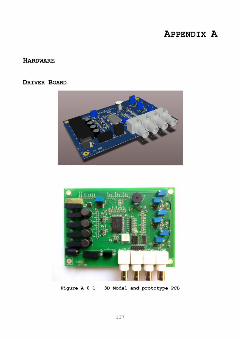
137
APPENDIX A
HARDWARE
DRIVER BOARD
Figure A-0-1 - 3D Model and prototype PCB
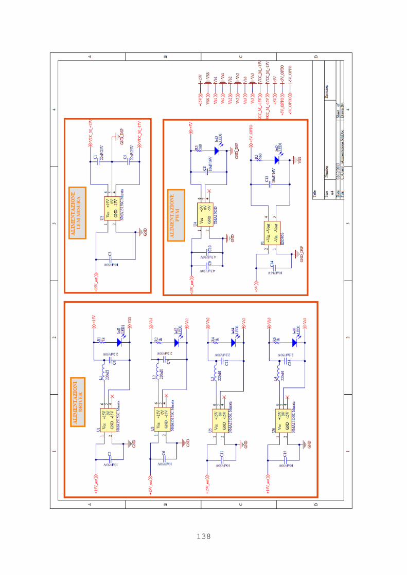
138
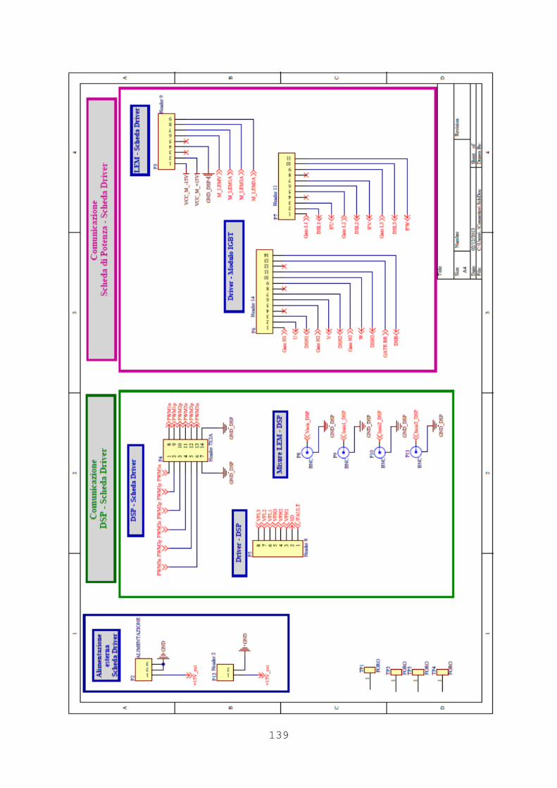
139

140

141

142

143
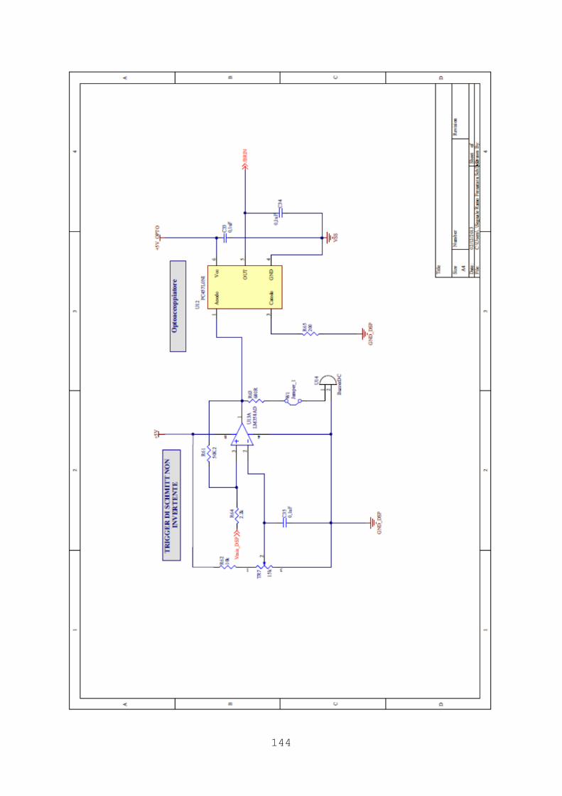
144

145
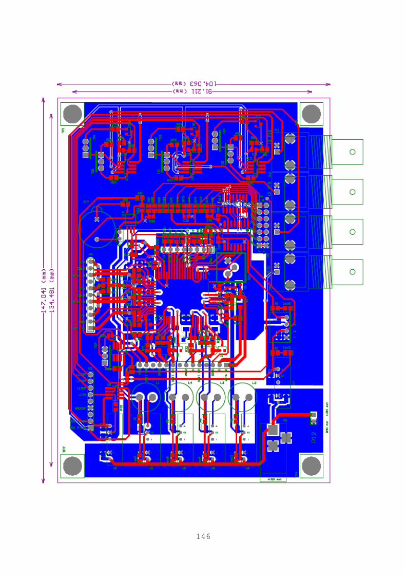
146
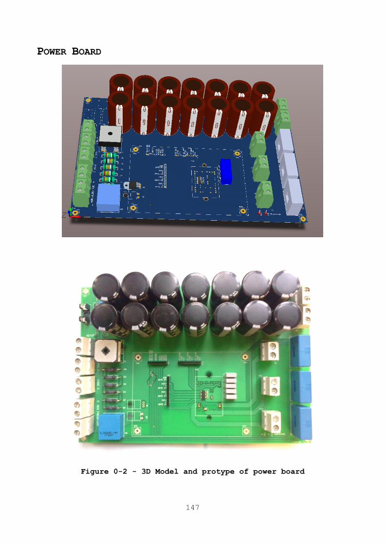
147
POWER BOARD
Figure 0-2 - 3D Model and protype of power board
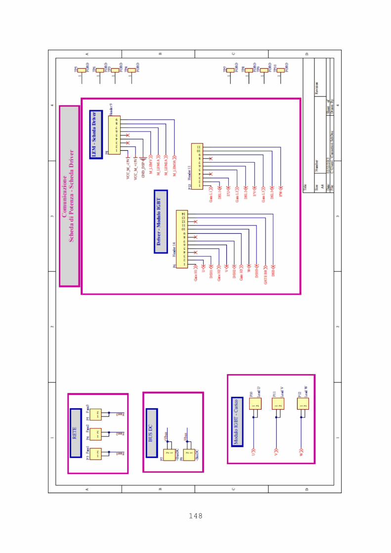
148

149

150
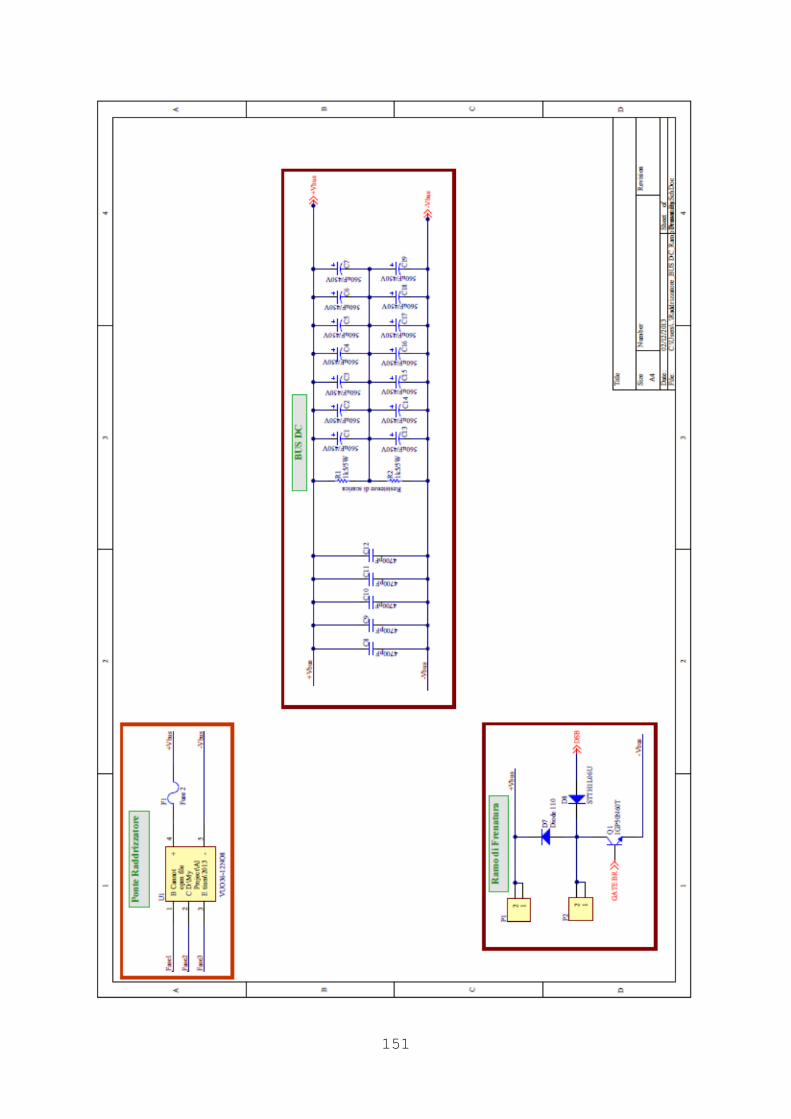
151

152

153
LIST OF PAPER OF GIANCARLO RINI
1. G. Rini, M. Mengoni, L. Zarri, A. Tani, G. Serra and D. Casadei, ―A Modulation Strategy for Matrix Converter with
Extended Control Range and Reduced Switching Power Losses‖,
ECCE 2013.
2. G. Rini, A. Tani, G. Serra, M. Mengoni, L. Zarri, D. Casadei, ―Dynamic Stator Current Sharing in Quadruple Three-Phase
Induction Motor Drives‖, IECON 2013.
3. G. Rini; Mengoni, M.; Zarri, L.; Tani, A.; Serra, G.; Casadei, D., "Modulation strategy with minimum switching
losses for three-phase AC-DC matrix converters", Power
Electronics and Applications (EPE'14-ECCE Europe), 2014 16th
European Conference
Top Related