


Languages
Pages
Legal

An LTE module for the
Network Simulator 3Giuseppe Piro, Nicola Baldo, Marco Miozzo
- 25 March 2011 -
Wns3 2011 – Barcelona (Spain)
25 Mar. 2011 Wns3 2011
Outline
About the Long Term Evolution (LTE)
Development of the LTE module for ns-3
Module description
Network devices (UE and eNB)
Radio Bearer Management and the RRC Entity
Channel and PHY models
AMC module and CQI feedbacks
Control Messages
Limitation and Future works

25 Mar. 2011 Wns3 2011
About the Long Term Evolution
First 3GPP release: Release 8 (Dec. 2004) (the “release of the
release" is 2008)
LTE has been designed for guaranteeing high capacity and data
rates, low cost deployments for cellular networks.
LTE will be the 4-th generation of cellular networks.
We need for a complete LTE simulator for testing
network performance and for implementing newer
algorithms/protocols
Long Term Evolution represents an emerging and
promising technology for providing a broadband
ubiquitous Internet access.
25 Mar. 2011 Wns3 2011
The development of the LTE module for ns-3
was carried out during the Google Summer of
Code 2010.
Development of the LTE module for ns-3
The module is built completely in C++.
It comprises 89 classes and approximately 9000 lines of code.
The module has been merged into ns-3.10 !
LTE is a very complex standard, and for this reason, at this time, it
is not yet possible the simulation a complete LTE system
However this contribution is fundamental since it set the basis for
developing such a complete tool
25 Mar. 2011 Wns3 2011
What features have been implemented ?
Network devices: User Equipment (UE) and enhanced NodeB
(eNB)
Part of Radio Resource Control (RRC)
MAC queues and the RLC instances (TM)
Data Radio Bearers (with their QoS parameters)
PHY layer model with Resource Block level granularity
Outdoor E-UTRAN channel model
DL Channel Quality Indicator (CQI) management
Adaptive Modulation and Coding (AMC) scheme for the downlink
Support for the downlink packet scheduler
LTE module description (1)

25 Mar. 2011 Wns3 2011
LTE module description (2)
Implemented E-UTRAN devices: UE
and eNB.
The core of the LTE module is
composed by both MAC and PHY
layers of an LTE device.
The LTE device has been conceived as a
container of several entities:
the IP classifier, the RRC entity, the
MAC entity, and the PHY layer.
Their actual integration is device-dependent, due the intrinsic ifferences between the
entities involved (UE vs. eNB).
The implementation of each of these entities depends on which the device have to
do.

25 Mar. 2011 Wns3 2011
The eNB network device
RRCRadio bearer
MAC
queue
RLC
entity
MAC
PHY
Classify packet into a proper queue
UPPER LAYERS
IP Classifier
DL Channel UL Channel
DL PHY UL PHY
AMC
ForwardUp
SendPacketBurst
Packet
Scheduler
SendIdealControlMessages
ReceiveIdealControlMessages
25 Mar. 2011 Wns3 2011
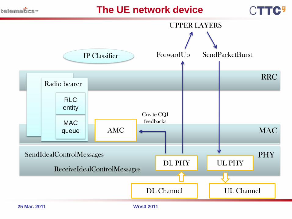
The UE network device
RRCRadio bearer
MAC
PHY
UPPER LAYERS
DL Channel UL Channel
DL PHY UL PHY
AMC
Create CQI
feedbacks
ForwardUp SendPacketBurst
MAC
queue
RLC
entity
IP Classifier
SendIdealControlMessages
ReceiveIdealControlMessages

25 Mar. 2011 Wns3 2011
In LTE networks, each flow is mapped into a logical connection named
bearer.
A Radio Bearer maps a flow into the bearer established between UE
and eNB.
We can have different type of radio bearers:
- Default Radio Bearer vs Data Radio Bearer
- GBR Radio Bearer vs non-GBR Radio Bearer
Each Radio Bearer has associated a set of QoS parameters (target delay,
minimum guaranteed bit rate, maximum guaranteed bit rate, class
identifier), called QoS class identifiers (QCIs).
The RRC entity manages active radio bearers for a given device.
Radio Bearer Management and the RRC Entity
25 Mar. 2011 Wns3 2011
Both Channel and PHY have been developed starting from the Spectrum Framework.
This framework allow us to accurately model the OFDMA PHY layer by:
defining a set of frequencies used at the PHY layer (Resource Block resolution)
modeling the Power Spectral Density of the transmitted/received signal
allowing the computation of the SINR of the received signal
We implemented the FDD channel access we need for 2 channels (the DL
channel and the UL channel) and for 2 PhySpectrum entities in the PHY layer.
We chose to use the SingleModelSpectrumChannel for modelling the LTE Channel.
The LteSpectrumPhy has been implemented extending the SpectrumPhy class.
LTE module extends the PropagationSpectrumModel for implementing the
propagation model for E-UTRAN interface.
Channel and PHY models (1)
25 Mar. 2011 Wns3 2011
Channel and PHY models (2)
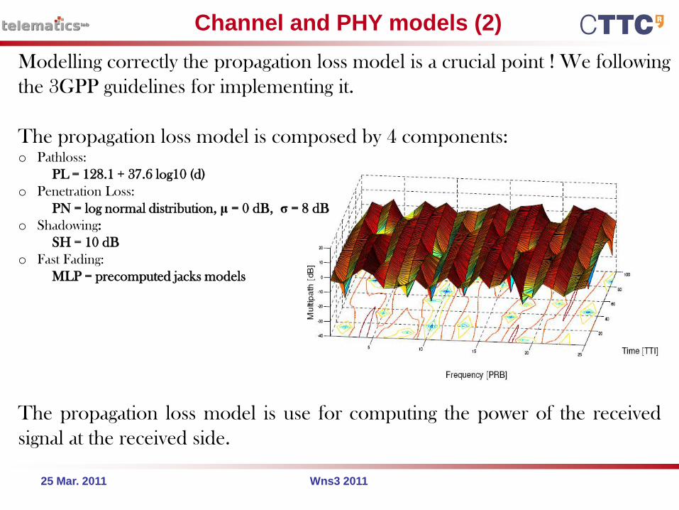
Modelling correctly the propagation loss model is a crucial point ! We following
the 3GPP guidelines for implementing it.
The propagation loss model is composed by 4 components:o Pathloss:
PL = 128.1 + 37.6 log10 (d)
o Penetration Loss:
PN = log normal distribution, μ = 0 dB, σ = 8 dB
o Shadowing:
SH = 10 dB
o Fast Fading:
MLP = precomputed jacks models
The propagation loss model is use for computing the power of the received
signal at the received side.
25 Mar. 2011 Wns3 2011
CQI management and AMC module (1)
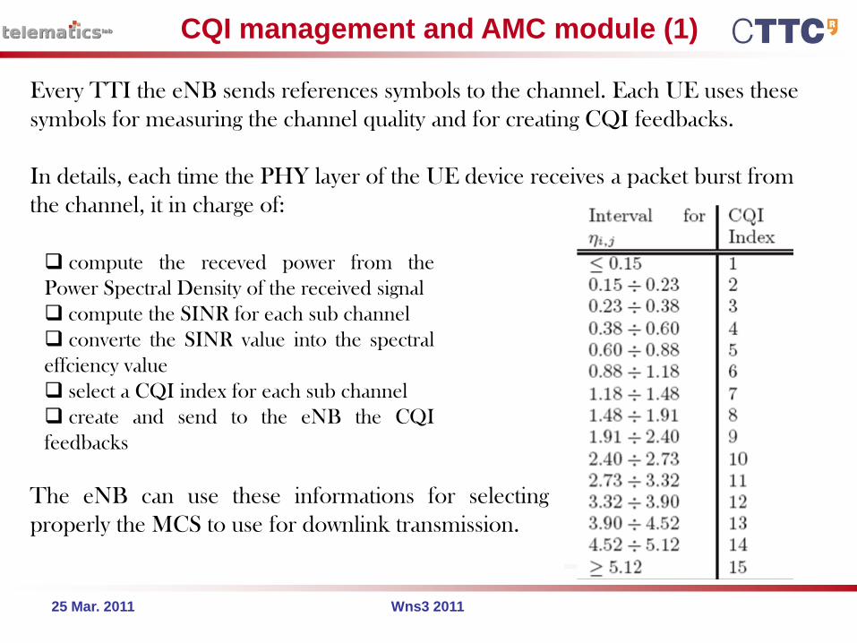
Every TTI the eNB sends references symbols to the channel. Each UE uses these
symbols for measuring the channel quality and for creating CQI feedbacks.
In details, each time the PHY layer of the UE device receives a packet burst from
the channel, it in charge of:
compute the receved power from the
Power Spectral Density of the received signal
compute the SINR for each sub channel
converte the SINR value into the spectral
effciency value
select a CQI index for each sub channel
create and send to the eNB the CQI
feedbacks
The eNB can use these informations for selecting
properly the MCS to use for downlink transmission.
25 Mar. 2011 Wns3 2011
CQI management and AMC module (2)
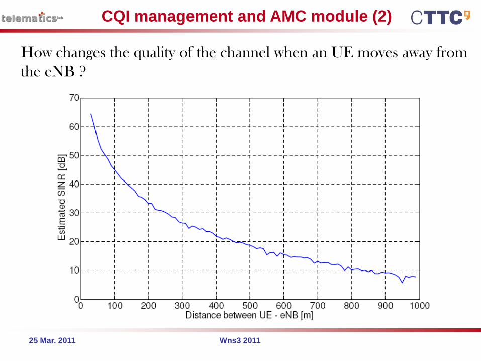
How changes the quality of the channel when an UE moves away from
the eNB ?

25 Mar. 2011 Wns3 2011
CQI management and AMC module (3)
How changes the quality of the channel when an UE moves away from
the eNB ?
25 Mar. 2011 Wns3 2011
Control Messages
Two control messages have been implented:
CQI feedback (feedbacks about the channel quality sends by the
UE to the eNB)
PDCCH messages (descriprion of the resource allocation sends
by the eNB to all the UE)
Messages are sent by using an ideal control channel. Why ideal ?
Information of control messages are not included into the burst of
data … but
they are exanged by devices directly, without passing follows the
StartTx and StartRx channel methods.
25 Mar. 2011 Wns3 2011
Limitation and Future Works
The LTE module is perfectly integrated into ns-3 !
We can simulate an LTE scenario with downlink flows.
…. BUT at this moment we have not:
- a standard compliant packet scheduler
- an interference model
- a PHY error model
- other RLC and MAC features (fragmentation, retransmission, ARQ
and H-ARQ)
-other !?!
We are working for improve the proposed module.
Thank you for your attention !
telematics.poliba.it/piro
Giuseppe Piro
Ph.D. Candidate at Polytechnic of Bari (Italy)
Top Related