


Languages
Pages
Legal

An inverted fluorescence microscope assembly.doc 1
An inverted fluorescence microscope assembly
1. Introduction
In certain instances it is desirable to construct one’s own inverted microscope optical ‘block’. One
of the reasons is that the cost for commercial microscope bodies is high (and increasing, as more
and more ‘features’ are added by the manufacturers). When dealing with fluorescence imaging
(either widefield or laser beam scanning), the microscope body can be extremely simple since epi-
illumination is most commonly employed and a transillumination condenser is not required.
Moreover, eyepieces are not needed if camera-based image acquisition is used.
We describe here details of a system developed by our group. Several versions of this basic
arrangement have been constructed and are in use in several laboratories. Although we have based
the system around Nikon CF160 ‘infinity’ optics, in principle optical systems from other
manufacturers can be used. We chose Nikon because individual optical components (e.g. tube
lenses) are readily available and because they are ready to lend components without requiring a
‘sale’.
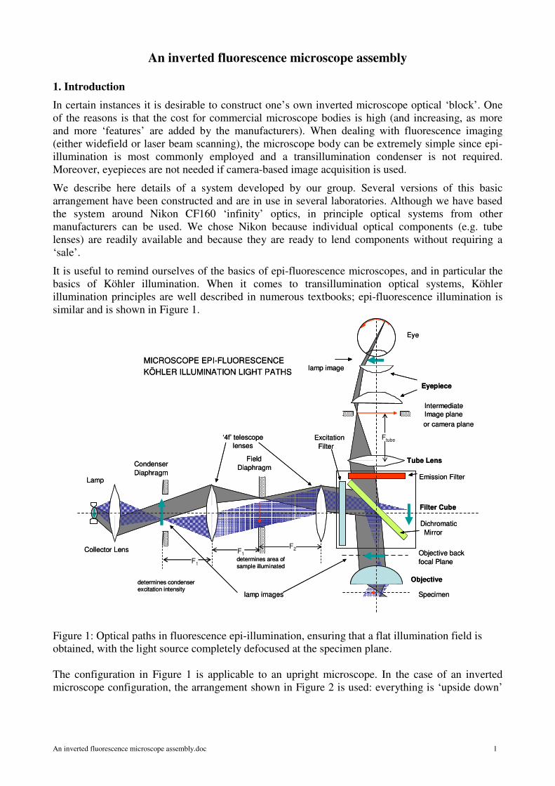
It is useful to remind ourselves of the basics of epi-fluorescence microscopes, and in particular the
basics of Köhler illumination. When it comes to transillumination optical systems, Köhler
illumination principles are well described in numerous textbooks; epi-fluorescence illumination is
similar and is shown in Figure 1.
Figure 1: Optical paths in fluorescence epi-illumination, ensuring that a flat illumination field is
obtained, with the light source completely defocused at the specimen plane.
The configuration in Figure 1 is applicable to an upright microscope. In the case of an inverted
microscope configuration, the arrangement shown in Figure 2 is used: everything is ‘upside down’
Objective
Specimen
Objective backfocal Plane
Eye
Eyepiece
Tube Lens
IntermediateImage plane
or camera plane
Emission Filter
Filter Cube
Dichromatic Mirror
ExcitationFilter
Lamp
lamp images
Condenser Diaphragm
FieldDiaphragm
lamp imageMICROSCOPE EPI-FLUORESCENCEKÖHLER ILLUMINATION LIGHT PATHS
Collector Lens
Ftube‘4f’ telescopelenses
determines area of sample illuminated
determines condenser excitation intensity
F1
F2F1
SCAN MIRROR HERE IN BEAM SCANNING SYSTEM

An inverted fluorescence microscope assembly.doc 2
and the output is deviated so as to be in the horizontal plane. The eyepiece is removed and a camera
sensor is placed in the tube lens image plane.
Figure 2: Optical paths in fluorescence inverted epi-illumination.
This configuration is employed in the system described here, with one modification. These days,
high pressure arc lamps (mercury or xenon) are slowly being replaced by more complex (but much
more stable) illumination sources using metal halide lamps which have a significantly longer
lifetime. Such sources are often coupled to the microscope with a liquid light guide the output of
which is collimated. We also use such a source, the Prior Lumen 200
(http://www.prior.com/productinfo_illumination_lumen.html), shown in Figure 3. Although the
output light guide (typically 3 mm diameter) of such a source could in fact be placed at the
condenser diaphragm position in Figure 2, we use an additional lens so as to be able to reduce the
source diameter and make it compatible with a 25 mm aperture shutter.
Figure 3: The Lumen 200 light guide coupled metal
halide light source
Objective
Specimen
Objective backfocal Plan\e
Emission Filter
Filter Cube
Dichromatic Mirror
ExcitationFilter
Lamp
Arc
Arc lamp images
Condenser Diaphragm
FieldDiaphragm
INVERTED MICROSCOPE EPI-FLUORESCENCE
KÖHLER ILLUMINATION LIGHT PATHS
Collector Lens
Camera image plane
Tube Lens
‘4f’ telescopelenses
This aperture determines area of sample illuminated
This aperture determines condenser excitation intensity
F1
F2
F1
Ftube
Mirror
An inverted fluorescence microscope assembly.doc 3
2. The microscope base
It is crucial to ensure that the microscope base is sturdy, free of vibration and as rigid as possible. In
commercial microscopes, this is achieved by using a metal cast housing, usually made of aluminium.
We start the description of our system with the microscope base and work backwards from this
(towards the image plane) and forwards (towards the objective). In our case, we build the
microscope directly onto an optical table using rigid spacers coupled to Thorlabs
(http://www.thorlabs.com/) cage system components. We start off with two aluminium blocks
which couple an LC6W ‘60 mm’ cube to the optical table. This cube houses a kinematically
adjusted 40 mm corner mirror (Comar 40 RX 03, http://www.comaroptics.com). Mounting rods
(Thorlabs ER8) are also mounted in these blocks, go through other optical assemblies and terminate
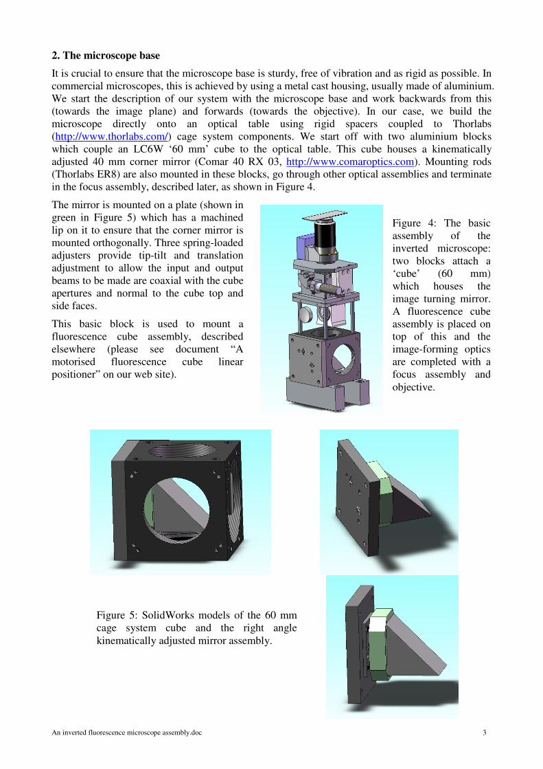
in the focus assembly, described later, as shown in Figure 4.
The mirror is mounted on a plate (shown in
green in Figure 5) which has a machined
lip on it to ensure that the corner mirror is
mounted orthogonally. Three spring-loaded
adjusters provide tip-tilt and translation
adjustment to allow the input and output
beams to be made are coaxial with the cube
apertures and normal to the cube top and
side faces.
This basic block is used to mount a
fluorescence cube assembly, described
elsewhere (please see document “A
motorised fluorescence cube linear
positioner” on our web site).
Figure 4: The basic
assembly of the
inverted microscope:
two blocks attach a
‘cube’ (60 mm)
which houses the
image turning mirror.
A fluorescence cube
assembly is placed on
top of this and the
image-forming optics
are completed with a
focus assembly and
objective.
Figure 5: SolidWorks models of the 60 mm
cage system cube and the right angle
kinematically adjusted mirror assembly.

An inverted fluorescence microscope assembly.doc 4
The output of this ‘cube’ is coupled to the microscope tube lens. A Nikon 200 mm focal length tube
lens can be readily obtained from Edmund Optics (part NT58-520, http://www.edmundoptics.com,
at reasonable cost (£169 at time of writing).
This is shown in Figure 6 and is mounted in a 60
mm plate (Thorlabs LCP03/M) held by mounting
rods, as shown in Figure 7.
Appropriate tubes could be used to couple a
‘C’mount camera such that the camera’s flange is
placed 133.7 mm away from the tube lens’ output
flange (the sensor to camera flange distance on
‘C’ mount camera is 17.53 ± 0.1 mm (ISO
10935:1996 / BS 7012-9:1997). In our
embodiment, we place an optical switch just
before the camera so as to be able to guide the
tube lens output to one of several output ports
(please see “A four position motorised optical
path selector” on our web site) as shown in
Figure 7. The same tube lens-camera flange
distance is ensured using tubes of appropriate
length.
We note that the tube lens-to-objective distance is
specified to be maintained to less than 200 mm.
This distance limitation is so as to prevent
vignetting of the output field, nominally around
22 mm for the combination of Nikon CF160 and
tube lens combination. However, when the output
field is somewhat smaller (e.g. a 2/3” CCD’s
diagonal distance is 11 mm), the maximal 200
mm distance requirement can be somewhat
relaxed. Indeed, should this arrangement be used
in a laser scanning system, the tube lens distance
should be set so as to ensure a stationary
excitation beam at the objective’s rear focal plane.
3. Objective mounting
The objective focusing assembly is arguably one
of the most critical and delicate parts of any
microscope. Commercial systems employ a
sophisticated mechanical arrangement which can
drive the objective in a ‘true’ vertical path with
nanometer resolution and it is common to find
multiple gearing arrangements use to provide
both coarse and fine focus adjustments. Such
assemblies are necessarily large and heavy in
order to ensure stability and precision of
movement. One of the consequences of this is
that fast focus changes are not readily achieved
and, when motorised systems are envisaged, such
speed limitations can often be troublesome.
Image plane
200 mm max.
M38 x 0.5
φ = 36 mm
29
21.85
Objective shoulder
151.2
Figure 6: the Nikon 200 mm tube lens. The
image plane must be maintained at 151.2
mm form the tube lens rear shoulder and the
objective should be placed at a distance not
significantly exceeding 200 mm from the
lens M38 threaded plane.
Figure 7: Mounting of the tube lens.

An inverted fluorescence microscope assembly.doc 5
In our arrangement, we also use two systems to provide coarse and fine movements. However, the
coarse movement is intended to be just that: it is not intended to provide continuous focusing, but
rather to drive the objective to a specific sample-dependent height so as to allow a very fine
focusing operation to be performed. The coarse movement uses a dc motor while the fine movement
uses a piezo-electric drive system. These systems are stacked on top of each other, as shown in
Figures 8 and 9, with the coarse movement arranged to be placed around a C6W Thorlabs cube.
The coarse microscope objective movement is based on a 90 degree bellcrank arrangement
(http://www.daerospace.com/MechanicalSystems/Bellcrank.php) similar to that used in a Comar
type 50 XT 45 elevation stage (this is the unit that gave us the idea!), but the bearings are replaced
with a precision ballslides. Two linear ballslides, Deltron type N-1AC (http://www.deltron.com/)
are used on wither side of a the C6W cube, holding a platform into which the piezo drive assembly
is screwed.
The coarse drive system can be operated with a
micrometer or, through a toothed belt and drive
wheel shown in Figure 9, by using a DC motor
drive. An appropriate drive system is described
elsewhere (please see “DC motor-encoder
position servo controller” on our web site.
The piezo objective drive assembly is
manufactured by Piezo Jena and available as
MIPOS 500 SG-UD with O-360-01 adaptor
(take care, the UD suffix is important!) available
from: http://www.piezojena.com/en/site/site/z-
axis-lens-positioning__196/. The associated
controller is a Eurocard-mounted version of their
12V40 controller, although other stand-alone
controllers would be equally suitable.
Although the open-loop control range for this
type of drive is +/- 250 µm, the closed-loop
control range does not exceed +/- 200 µm; this is
more than sufficient to take care of sample
height variations once the coarse focus is set.
Figure 8: SolidWorks model of the inverted
microscope’s focusing system.
Figure 9: The inverted microscope’s focusing
system showing details of the micrometer-
driven paddle drive (top) and the vertical
linear stages (right).

An inverted fluorescence microscope assembly.doc 6
The C6W cube around the coarse drive serves a secondary, but nevertheless very useful purpose: a
sampling power meter can be inserted into one of the side ports. Such a power meter is described in
the note “Metering systems to determine excitation intensities in fluorescence microscopy”
available on our web site.
4. Excitation path
The fluorescence excitation optical train starts with the metal halide lamp, light-guide coupled (light
guide diameter 3 mm) to a ∼50 mm focal length collimating lens housed within a Nikon bayonet
mount attachment. This is camped into a female bayonet mount attached to a Thorlabs LCP03/M
plate, as shown in Figure 10. Although the female bayonet mounts are available from Nikon, lately
delivery times have become significant and other users may prefer to mount the lens assembly
directly within the LCP03/M plate.
Figure 10. SolidWorks model of the light guide collimating lens assembly.
The spectral output from the lamp/light guide assembly is not particularly flat but is quite adequate
for the majority of visible (and NIR) fluorophores as shown in Figure 11.
Figure 11: Lumen 200 output spectrum
A 50 mm diameter 200 mm focal length lens, mounted in a Thorlabs LCP01/M 60 mm cageplate (a
LCP01T/M would have been better, but was not available at time of system development) is used
to provide a 12 mm image of the light guide on the condenser diaphragm aperture (a Thorlabs
An inverted fluorescence microscope assembly.doc 7
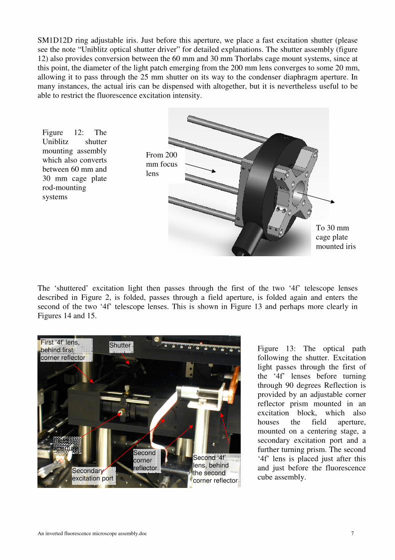
SM1D12D ring adjustable iris. Just before this aperture, we place a fast excitation shutter (please
see the note “Uniblitz optical shutter driver” for detailed explanations. The shutter assembly (figure
12) also provides conversion between the 60 mm and 30 mm Thorlabs cage mount systems, since at
this point, the diameter of the light patch emerging from the 200 mm lens converges to some 20 mm,
allowing it to pass through the 25 mm shutter on its way to the condenser diaphragm aperture. In
many instances, the actual iris can be dispensed with altogether, but it is nevertheless useful to be
able to restrict the fluorescence excitation intensity.
The ‘shuttered’ excitation light then passes through the first of the two ‘4f’ telescope lenses
described in Figure 2, is folded, passes through a field aperture, is folded again and enters the
second of the two ‘4f’ telescope lenses. This is shown in Figure 13 and perhaps more clearly in
Figures 14 and 15.
From 200
mm focus
lens
To 30 mm
cage plate
mounted iris
Figure 12: The
Uniblitz shutter
mounting assembly
which also converts
between 60 mm and
30 mm cage plate
rod-mounting
systems
Figure 13: The optical path
following the shutter. Excitation
light passes through the first of
the ‘4f’ lenses before turning
through 90 degrees Reflection is
provided by an adjustable corner
reflector prism mounted in an
excitation block, which also
houses the field aperture,
mounted on a centering stage, a
secondary excitation port and a
further turning prism. The second
‘4f’ lens is placed just after this
and just before the fluorescence
cube assembly.
First ‘4f’ lens, behind first corner reflector
Shutter
Field aperture
Second corner reflector
Second ‘4f’ lens, behind the second corner reflector
Secondary excitation port

An inverted fluorescence microscope assembly.doc 8
The full optical path diagram is shown in Figure 16. All of the optical components can be readily
obtained for the usual suppliers and these are listed overleaf, in Table 1.
Figure 16: Plan view of the excitation optical path.
Figure 14: The optical excitation
path following the shutter, view
from side of instrument.
Figure 15: The optical excitation path following the
shutter, view from shutter side.

An inverted fluorescence microscope assembly.doc 9
Table 1: Fluorescence excitation optical components
Component
Description Part number Supplier
Collector lens, achromat φ = 50.8 mm 200 mm fl AC508-200-A1 Thorlabs
Optical shutter 25 mm fast shutter VS25S2ZM1 Uniblitz
Condenser diaphragm Ring activated 12.5 mm SM1D12D Thorlabs
First ‘4f’ lens, achromat φ = 25.4 mm 100 mm fl AC254-100-A1 Thorlabs
First turning mirror 25 x 25 x 25 mm MRA25-F01 Thorlabs
Field diagram Ring activated 12.5 mm SM1D12D Thorlabs
Second turning mirror 25 x 25 x 25 mm MRA25-F01 Thorlabs
Second ‘4f’ lens, achromat φ = 25.4 mm 150 mm fl AC254-150-A1 Thorlabs
5. System images
Real-life and model images of the complete microscope system are presented on subsequent pages
in Figures 17-20. They are essentially self-explanatory. Details of the other subsystems can be
found on complementary technical notes, which should be read in conjunction with this note.
Figure 17: The instrument from the side. To the left of the shutter, behind a protective
cover, are placed optics associated with laser beam scanning, described separately.

An inverted fluorescence microscope assembly.doc 10
Figure 18: The completed
instrument, showing the
optical path switch (upper
bottom left) which couples
the output of the tube lens
to the camera or two a laser
scanning path, described
separately, and terminating
in a photomultiplier
detector (white box in
upper left side).
The middle panel shows a
bird’s eye view of a model
of the instrument.
The bottom panel shows
the completed, enclosed
instrument.
Camera
Descanned emission light path
Scanned beam excitation path
Scanned beam excitation/emission beam splitter
Widefield excitation
Optical beam switch
Scanned beam detection
Widefield fluorescence ‘cubes’
An inverted fluorescence microscope assembly.doc 11
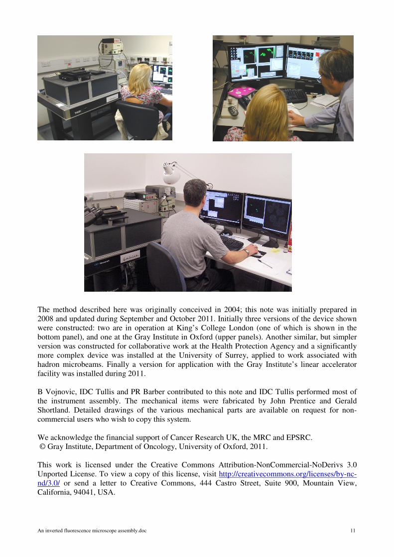
The method described here was originally conceived in 2004; this note was initially prepared in
2008 and updated during September and October 2011. Initially three versions of the device shown
were constructed: two are in operation at King’s College London (one of which is shown in the
bottom panel), and one at the Gray Institute in Oxford (upper panels). Another similar, but simpler
version was constructed for collaborative work at the Health Protection Agency and a significantly
more complex device was installed at the University of Surrey, applied to work associated with
hadron microbeams. Finally a version for application with the Gray Institute’s linear accelerator
facility was installed during 2011.
B Vojnovic, IDC Tullis and PR Barber contributed to this note and IDC Tullis performed most of
the instrument assembly. The mechanical items were fabricated by John Prentice and Gerald
Shortland. Detailed drawings of the various mechanical parts are available on request for non-
commercial users who wish to copy this system.
We acknowledge the financial support of Cancer Research UK, the MRC and EPSRC.
© Gray Institute, Department of Oncology, University of Oxford, 2011.
This work is licensed under the Creative Commons Attribution-NonCommercial-NoDerivs 3.0
Unported License. To view a copy of this license, visit http://creativecommons.org/licenses/by-nc-
nd/3.0/ or send a letter to Creative Commons, 444 Castro Street, Suite 900, Mountain View,
California, 94041, USA.
Top Related