


Languages
Pages
Legal


139-0357-03.1 Page 1 of 8
All sound systems need a power panel - why not have ONE TOUCH AC power control?
Motorized circuit breakers sequence sound system AC power!
Low voltage cabinetshouse
sequencer circuit boards
MSLC 326-xx
Modular Sequencing Load Center
MSLC 341-xxModular
Sequencing Load Center
MSP 341-xx Modular Sequencing Panelboard - The Electrician's choice
Separate
ISOLATEDISOLATEDTECHNICAL
GROUNDcabinet
LynTec Modular Sequencing series panels add branch circuit sequencing to the main and branch circuit breaker functions normally found in a Load Center or Panelboard.
How they work
Applies AC to low level, front-end electronics... waits for them to stabilize... (clicks and pops are ignored by un-powered power amplifi ers)...
AC is then sequenced to power amplifi ers to spread high inrush currents over time.
Protects valuable loudspeaker systems by delaying turn-on until all low level equipmenthas stabilized.
LynTec Modular Sequencing series Power Panels
BENEFITS
ONE TOUCH remote power control
• Immediate visual feedback provided by fl ashing ON switch.
• Light stays ON to verify sequence completion.• Process is reversed for turn-off sequence.• May be controlled from one to six locations.• Multiple sequencing panels may be daisy-chained for larger systems.
Reduced installation labor
• One wall-mounted, sequenced power panel feeds AC power to all rack and console receptacles.
Low power consumption
• BMB (Bolt-on) and MB (Clip-on) series motorized circuit breakers require no holding current (like DC relays) or heat sinks (like solid state relays).
• Runs cool — lasts long.
Automatic load shedding and BROWNOUT protection
• A voltage sensing system automatically sheds the load when AC mains voltage drops below 95 volts for 2 seconds. • Capacitor-stored energy zips-off all circuits 2 seconds after power fails. • The system automatically re-sequences without operator intervention when stable voltage (above 105 volts for 5 seconds) resumes.• Reduces the start-up load for auxiliary power units.
• Smart wake-up is ideal for unatt ended systems.
Kill
• Emergency instant shutdown may be triggered by an external contact closure. • System automatically re-sequences when contact opens.
HurryOff — Ohh..... no..... switch – Kill without restart
• By holding any OFF switch down for 2 seconds, the operator can trigger an instant shutdown with no automatic restart.
ONE TOUCHREMOTE POWER CONTROL
SHOWN ACTUAL SIZE
Green LED illuminated Red
SS-2 Sequencer Switch SetOne SS-2 switch set is supplied with each panel.

Planning and Layout Worksheet — As-built door labelMSP 141-xx Sound System Sequencing Panel
Breaker types, sizes, positions and connections
Document # 139-0340-02 MSP 141 Planner 11/1/06
Job______________________________________
Panel ____________________________________
Comments________________________________
_________________________________________
by________________________ Date___________ Each motorized breaker is controlled by a sequencer. As-built door label example: Step #_______ (1a) # in parenthesis is suggested breaker connection in sequencer. Bold line around box is the suggested sequencer board: #1(Top), #2, #3, or #4. Fill in box to indicate which sequencer board this breaker is connected to.
Top Board 1. 1 board model:
MSP 141-12 Panelboard
Board 2. 2 board model:
MSP 141-24 Panelboard
Boards 4 & 5.
4 board models:
MSP 141-48 Panelboard
5 board model
used for multiple systems:
MSP 141-60 Panelboard
Board 3. 3 board model:
MSP 141-36 Panelboard
MS-12 Sequencer circuit boards in left-hand, low voltage cabinet.
_____Amp. ^Un-motorized. ^Motorized-Step # ____(1a)
_____Amp. ^Un-motorized. ^Motorized-Step # ____(2a)
_____Amp. ^Un-motorized. ^Motorized-Step # ____(3a)
_____Amp. ^Un-motorized. ^Motorized-Step # ____(4a)
_____Amp. ^Un-motorized. ^Motorized-Step # ____(5a)
_____Amp. ^Un-motorized. ^Motorized-Step # ____(6a)
_____Amp. ^Un-motorized. ^Motorized-Step # ____(1a)
_____Amp. ^Un-motorized. ^Motorized-Step # ____(2a)
_____Amp. ^Un-motorized. ^Motorized-Step # ____(3a)
_____Amp. ^Un-motorized. ^Motorized-Step # ____(1b)
_____Amp. ^Un-motorized. ^Motorized-Step # ____(2b)
_____Amp. ^Un-motorized. ^Motorized-Step # ____(3b)
_____Amp. ^Un-motorized. ^Motorized-Step # ____(5b)
_____Amp. ^Un-motorized. ^Motorized-Step # ____(6b)
_____Amp. ^Un-motorized. ^Motorized-Step # ____(1b)
_____Amp. ^Un-motorized. ^Motorized-Step # ____(2b)
_____Amp. ^Un-motorized. ^Motorized-Step # ____(3b)
_____Amp. ^Un-motorized. ^Motorized-Step # ____(4b)
_____Amp. ^Un-motorized. ^Motorized-Step # ____(5b)
_____Amp. ^Un-motorized. ^Motorized-Step # ____(6b)
_____Amp. ^Un-motorized. ^Motorized-Step # ____(1b)
_____Amp. ^Un-motorized. ^Motorized-Step # ____(2b)
Which
Boar
d?
10A un-motorized breaker supplied installed.
_____Amp. ^Un-motorized. ^Motorized-Step # ____(4b)
1
3
5
7
9
11
13
15
17
19
21
23
25
27
29
31
33
35
37
39
41 SEQUENCER POWER SEQUENCER POWER
40
38
36
34
32
30
28
26
24
22
20
18
16
14
12
10
8
6
4
2
1a 1a
Cabinet outline Surface mount only
Outside dimensions 36" w., 50" h., 6.13" d.
F eed 4/0 max.
Iso-Tech Ground
Branches: 46 position
14 - 4 ga.
Isolated I s o l a t e d Te c h nical T e c h n i c a l Gr ound G r o u n d
Bar B a r
Fe e d 2/0 max.
High v o ltage inter i or ma y be field in v e r t ed f or top f e ed.
MAIN
Sequencer
1 Sequencer
2 Sequencer
3 Sequencer
4 Sequencer
5
SEQ UENCER PO WER
NQOD Panel225A Copper Bus
#4 — 300 kcmil Al/Cu
Main Breakers availableQGL22xxx series — All 65k AIRPart# suffix — Bold face = Amps
-MQG2070, -MQG2080, -MQG2090,-MQG2100, -MQG2110, -MQG2125,
-MQG2150, -MQG2175, -MQG2200, -MQG2225.
LynTec MSP 141-xx (65k AIR main)
Modular Sequencing Panelboard
S N / S
N /
225A Copper
Bus
Transfer as-built information to the door label upon completion.
Keep this sheet for
as-built documentation
Available as PDF download www.lyntec.com/139-0340_MSP141Plnr.pdf
Low voltage control Wiring Diagram located inside
left cover. www.lyntec.com/139-0327_SequencerLV_Wiring.pdf

6.13"
50.00"
36.00"
2.00"15.00"
32.00"
44.00"
3.00"
Feed4/0 max.
Iso-TechGround
Branches:
46 position14 - 4 ga.
IsolatedIsolatedTechnicalTechnicalGroundGround
BarBar
Feed2/0 max.
High voltage interior may be field inverted for top feed
Sequencer
1Sequencer
2Sequencer
3Sequencer
4Sequencer
5
139-0341-01 MSP 141 Outline Drawing 11/1/06
LynTec MSP 141-xx (25k AIR main)
[Special order, NCNRSpecial order, NCNR]
Outline Drawing
C/L 8.50"
Square D NQOD MB Panelwith LynTec sidecars.
225A Copper Bus
Main Breakers available
QGL22xxx series — All 65k AIR
Part# suffix — Bold face = Amps-MQG2070, -MQG2080, -MQG2090, -MQG2100,-MQG2110, -MQG2125,-MQG2150, -MQG2175,-MQG2100, -MQG2200,
-MQG2225.
Outside dimensions36" w., 50" h., 6.13" d.
#4 — 300 kcmil Al/Cu
MAIN
SEQUENCERPOWER
S N/
S N/
225ACopper
Bus
Enclosuregroundbar.23 position14-4 ga.
1.5" I.D.wiringaccessnipples
betweensidecars
&Panelboard
Derived from Digest 173 — page 6-21
Thermal-magnetic Molded Case Circuit Breakers
250 Ampere FrameClass 734
6
CIR
CU
IT B
RE
AK
ER
S
© 2004 Schneider ElectricAll Rights Reserved4/1/04
www.SquareD.comFor the most up-to-date information
Accessories . . . . . . . . . . . . . . . . . . . . . . . . . . pages 6-36–6-38Optional Lugs . . . . . . . . . . . . . . . . . . . . . . . . . pages 6-43, 6-44Dimensions . . . . . . . . . . . . . . . . . . . . . . . . . . . pages 6-49, 6-50Enclosures. . . . . . . . . . . . . . . . . . . . . . . . . . . . pages 6-51–6-54
Interrupting Ratings (kA)
QD QG
240 V 25 65
Replacement lugs are not available for POWERPACT Q-frame circuit breakers.Lugs for the POWERPACT Q-frame circuit breakers accept (1) #4–300 kcmil.
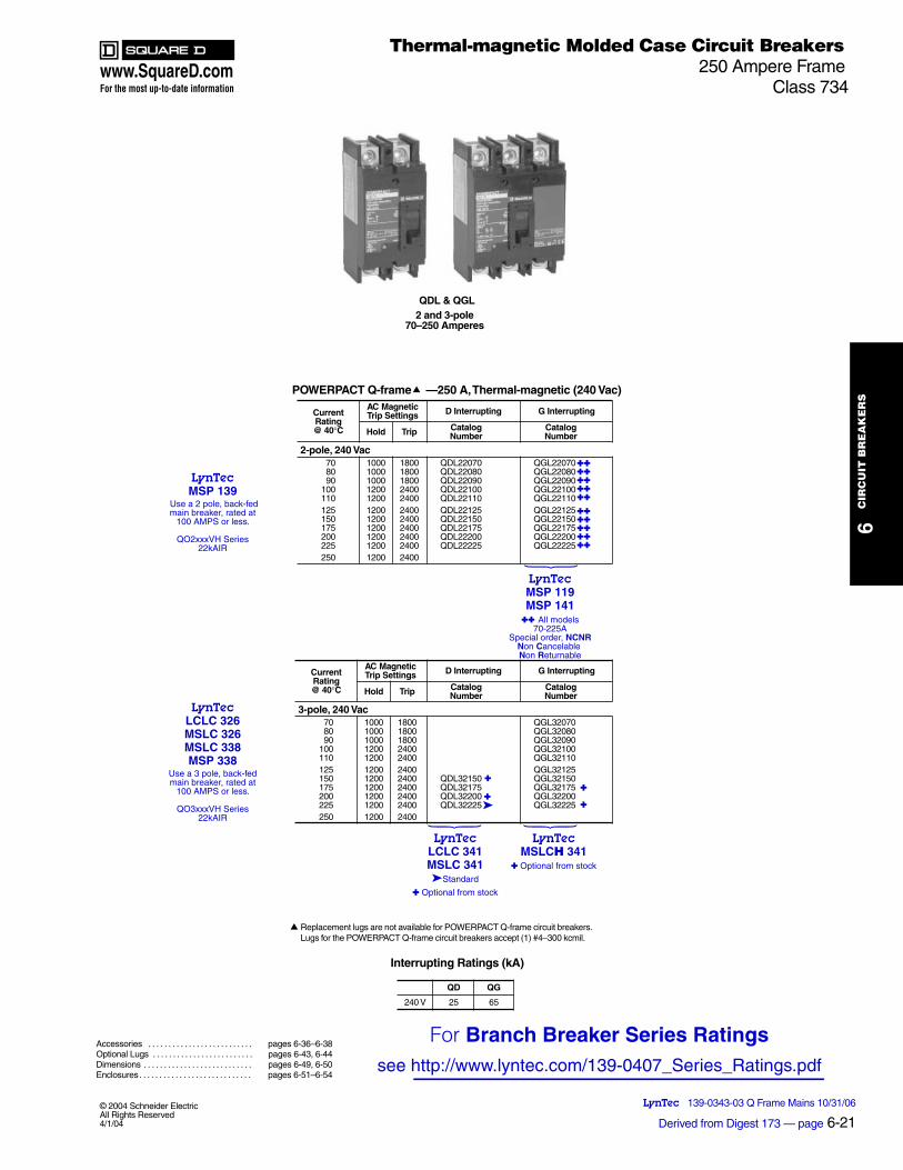
POWERPACT Q-frame
—250 A, Thermal-magnetic (240 Vac)
Current Rating @ 40°C
AC Magnetic Trip Settings D Interrupting G Interrupting
Hold Trip Catalog Number
Catalog Number
2-pole, 240 Vac
70 1000 1800
QDL22070
QGL22070
80 1000 1800
QDL22080
QGL22080
90 1000 1800
QDL22090
QGL22090
100 1200 2400
QDL22100
QGL22100
110 1200 2400
QDL22110
QGL22110
125 1200 2400
QDL22125
QGL22125
150 1200 2400
QDL22150
QGL22150
175 1200 2400
QDL22175
QGL22175
200 1200 2400
QDL22200
QGL22200
225 1200 2400
QDL22225
QGL22225
250 1200 2400
3-pole, 240 Vac
70 1000 1800
QGL32070
80 1000 1800
QGL32080
90 1000 1800
QGL32090
100 1200 2400
QGL32100
110 1200 2400
QGL32110
125 1200 2400
QGL32125
150 1200 2400
QDL32150
QGL32150
175 1200 2400
QDL32175
QGL32175
200 1200 2400
QDL32200
QGL32200
225 1200 2400
QDL32225
QGL32225
250 1200 2400
QDL & QGL 2 and 3-pole
70–250 Amperes
LynTec 139-0343-03 Q Frame Mains 10/31/06
Current Rating @ 40°C
AC Magnetic Trip Settings D Interrupting G Interrupting
Hold Trip Catalog Number
Catalog Number
LynTecMSP 119MSP 141
All models70-225A
Special order, NCNRNon Cancelable Non Returnable
LynTecMSLCH 341
Optional from stock
LynTecLCLC 341MSLC 341Standard
Optional from stock
LynTecMSP 139
Use a 2 pole, back-fedmain breaker, rated at
100 AMPS or less.
QO2xxxVH Series22kAIR
For Branch Breaker Series Ratingssee http://www.lyntec.com/139-0407_Series_Ratings.pdf
LynTecLCLC 326MSLC 326MSLC 338MSP 338
Use a 3 pole, back-fedmain breaker, rated at
100 AMPS or less.
QO3xxxVH Series22kAIR
www.SquareD.comFor the most up-to-date information
8-2
Series RatingsFor NQOD and NF PanelboardsClass 1630, 1670
8P
AN
EL
BO
AR
DS
© 2006 Schneider ElectricAll Rights Reserved
8/24/06
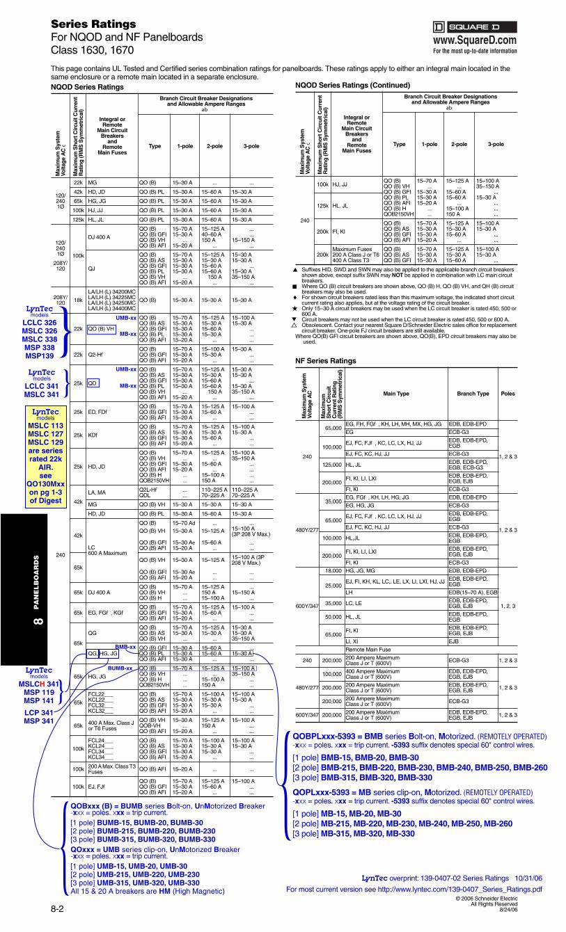
This page contains UL Tested and Certified series combination ratings for panelboards. These ratings apply to either an integral main located in the same enclosure or a remote main located in a separate enclosure.
Suffixes HID, SWD and SWN may also be applied to the applicable branch circuit breakers shown above, except suffix SWN may NOT be applied in combination with LC main circuit breakers.Where QO (B) circuit breakers are shown above, QO (B) H, QO (B) VH, and QH (B) circuit breakers may also be used.For shown circuit breakers rated less than this maximum voltage, the indicated short circuit current rating also applies, but at the voltage rating of the circuit breaker.Only 15–30 A circuit breakers may be used when the LC circuit breaker is rated 450, 500 or 600 A.Circuit breakers may not be used when the LC circuit breaker is rated 450, 500 or 600 A.Obsolescent. Contact your nearest Square D/Schneider Electric sales office for replacement circuit breaker. One-pole FJ circuit breakers are still available.
Where QO(B) GFI circuit breakers are shown above, QO(B), EPD circuit breakers may also be used.
8/24/06
NQOD Series Ratings
Max
imum
Sys
tem
Volta
ge
AC
c
Max
imum
Sho
rt C
ircu
it C
urre
nt
Rat
ing
(RM
S S
ymm
etri
cal)
Integral orRemote
Main CircuitBreakers
andRemote
Main Fuses
Branch Circuit Breaker Designations and Allowable Ampere Ranges
ab
Type 1-pole 2-pole 3-pole
120/2401Ø
22k MG QO (B) 15–30 A ... ...
42k HD, JD QO (B) PL 15–30 A 15–60 A 15–30 A
65k HG, JG QO (B) PL 15–30 A 15–60 A 15–30 A
100k HJ, JJ QO (B) PL 15–30 A 15–60 A 15–30 A
125k HL, JL QO (B) PL 15–30 A 15–60 A 15–30 A
120/2401Ø
208Y/120
100k
DJ 400 A
QO (B) 15–70 A 15–125 A ...QO (B) GFI 15–30 A 40–60 A ...QO (B) VH ... 150 A 15–150 AQO (B) AFI 15–20 A ... ...
QJ
QO (B) 15–70 A 15–125 A 15–30 AQO (B) AS 15–30 A 15–30 A 15–30 AQO (B) GFI 15–30 A 15–60 A ...QO (B) PL 15–30 A 15–60 A 15–30 AQO (B) VH ... 150 A 35–150 AQO (B) AFI 15–20 A ... ...
208Y/120 18k
LA/LH (L) 34200MCLA/LH (L) 34225MCLA/LH (L) 34250MCLA/LH (L) 34400MC
QO (B) 15–30 A 15–30 A 15–30 A
240
22k QO (B) VH
QO (B) 15–70 A 15–125 A 15–100 AQO (B) AS 15–30 A 15–30 A 15–30 AQO (B) GFI 15–30 A 15–60 A ...QO (B) PL 15–30 A 15–30 A ...QO (B) AFI 15–20 A ... ...
22k Q2-HfQO (B) 15–70 A 15–100 A 15–30 AQO (B) GFI 15–30 A 15–30 A ...QO (B) AFI 15–20 A ... ...
25k QD
QO (B) 15–70 A 15–125 A 15–30 AQO (B) AS 15–30 A 15–30 A 15–30 AQO (B) GFI 15–30 A 15–60 A ...QO (B) PL 15–30 A 15–60 A 15–30 AQO (B) VH ... 150 A 35–150 AQO (B) AFI 15–20 A ... ...
25k ED, FDfQO (B) 15–70 A 15–125 A 15–100 AQO (B) GFI 15–30 A 15–60 A ...QO (B) AFI 15–20 A ... ...
25k KDfQO (B) 15–70 A 15–125 A 15–100 AQO (B) AS 15–30 A 15–30 A 15–30 AQO (B) GFI 15–30 A 15–60 A ...QO (B) AFI 15–20 A ... ...
25k HD, JD
QO (B) 15–70 A 15–125 A 15–100 AQO (B) VH ... ... 35–150 AQO (B) GFI 15–30 A 15–60 A ...QO (B) AFI 15–20 A ... ...QO (B) H ... 15–100 A ...QOB2150VH ... 150 A ...
42k
LA, MA Q2L-Hf ... 110–225 A 110–225 AQDL ... 70–225 A 70–225 A
MG QO (B) VH 15–30 A 15–30 A 15–30 A
HD, JD QO (B) PL 15–30 A 15–60 A 15–30 A
42k
LC600 A Maximum
QO (B) 15–70 Ad ... ...QO (B) VH 15–30 A 15–125 A 15–100 A
(3P 208 V Max.)
QO (B) GFI 15–30 Ae 15–60 A ...QO (B) AFI 15–20 A ... ...
65kQO (B) VH 15–30 A 15–125 A 15–100 A (3P
208 V Max.)
QO (B) GFI 15–30 Ae ... ...QO (B) AFI 15–20 A ... ...
65k DJ 400 AQO (B) 15–70 A 15–125 A ...QO (B) VH ... 150 A 15–150 AQO (B) H ... 15–100 A ...
65k EG, FGf , KGfQO (B) 15–70 A 15–125 A 15–100 AQO (B) GFI 15–30 A 15–60 A ...QO (B) AFI 15–20 A ... ...
65k
QGQO (B) 15–70 A 15–125 A 15–30 AQO (B) AS 15–30 A 15–30 A 15–30 AQO (B) VH ... ... 35–150 A
QG, HG, JGQO (B) GFI 15–30 A 15–60 A ...QO (B) PL 15–30 A 15–60 A 15–30 AQO (B) AFI 15–30 A ... ...
65k HG, JG
QO (B) 15–70 A 15–125 A 15–100 AQO (B) VH ... ... 35–150 AQO (B) H ... 15–100 A ...QOB2150VH ... 150 A ...
65k
FCL22___ QO (B) 15–70 A 15–100 A 15–100 AKCL22___ QO (B) AS 15–30 A 15–30 A 15–30 AFCL32___ QO (B) GFI 15–30 A 15–30 A ...KCL32___ QO (B) AFI 15–20 A ... ...
65k 400 A Max. Class J or T6 Fuses
QO (B) VH 15–30 A 15–125 A 15–100 AQOB-VH ... 150 A ...QO (B) AFI 15–20 A ... ...
100k
FCL24___ QO (B) 15–70 A 15–100 A 15–100 AKCL24___ QO (B) AS 15–30 A 15–30 A 15–30 AFCL34___ QO (B) GFI 15–30 A 15–30 A ...KCL34___ QO (B) AFI 15–20 A ... ...
100k 200 A Max. Class T3 Fuses QO (B) AFI 15–20 A ... ...
100k EJ, FJfQO (B) 15–70 A 15–125 A 15–100 AQO (B) GFI 15–30 A 15–60 A ...QO (B) AFI 15–20 A ... ...
240
100k HJ, JJQO (B) 15–70 A 15–125 A 15–100 AQO (B) VH ... ... 35–150 AQO (B) GFI 15–30 A 15–60 A ...
125k HL. JL
QO (B) PL 15–30 A 15–60 A 15–30 AQO (B) AFI 15–20 A ... ...QO (B) H ... 15–100 A ...QOB2150VH ... 150 A ...
200k FI, KI
QO (B) 15–70 A 15–125 A 15–100 AQO (B) AS 15–30 A 15–30 A 15–30 AQO (B) GFI 15–30 A 15–60 A ...QO (B) AFI 15–20 A ... ...
200kMaximum Fuses200 A Class J or T6400 A Class T3
QO (B) 15–70 A 15–125 A 15–100 AQO (B) AS 15–30 A 15–30 A 15–30 AQO (B) GFI 15–30 A 15–60 A ...
NF Series Ratings
Max
imum
Sys
tem
Vo
ltag
e A
C
Max
imum
S
hort
Cir
cuit
Cur
rent
Rat
ing
(R
MS
Sym
met
rica
l)
Main Type Branch Type Poles
240
65,000EG, FH, FGf , KH, LH, MH, MX, HG, JG EDB, EDB-EPD
1, 2 & 3
3G-BCEGE
100,000EJ, FC, FJf , KC, LC, LX, HJ, JJ EDB, EDB-EPD,
EGB
3G-BCEJJ ,JH ,CK ,CF ,JE
125,000 HL, JL EDB, EDB-EPD, EGB, ECB-G3
200,000FI, KI, LI, LXI EDB, EDB-EPD,
EGB, EJB
3G-BCEIK ,IF
480Y/277
35,000EG, FGf , KH, LH, HG, JG EDB, EDB-EPD
1, 2 & 3
3G-BCEGJ ,GH ,GE
65,000EJ, FC, FJf , KC, LC, LX, HJ, JJ EDB, EDB-EPD,
EGB
3G-BCEJJ ,JH ,CK ,CF ,JE
100,000 HL,JL EDB, EDB-EPD, EGB
200,000FI, KI, LI, LXI EDB, EDB-EPD,
EGB, EJB
3G-BCEIK ,IF
600Y/347
DPE-BDE ,BDEGM ,GJ ,GH000,81
1, 2, 3
25,000EJ, FI, KH, KL, LC,. LE, LX, LI, LXI, HJ, JJ EDB, EDB-EPD,
EGB
BGE ,)A 07–51(BDEHL
35,000 LC, LE EDB, EDB-EPD, EGB, EJB
50,000 HL, JL EDB, EDB-EPD, EGB
65,000FI, KI EDB, EDB-EPD,
EGB, EJB
BJEIX ,IL
Remote Main Fuse
240 200,000 200 Ampere Maximum Class J or T (600V) ECB-G3 1, 2 & 3
480Y/277
100,000 400 Ampere Maximum Class J or T (600V)
EDB, EDB-EPD, EGB, EJB
1, 2 & 3200,000 200 Ampere Maximum Class J or T (600V)
EDB, EDB-EPD, EGB, EJB
200,000 200 Ampere Maximum Class J or T (600V) ECB-G3
600Y/347 200,000 200 Ampere Maximum Class J or T (600V)
EDB, EDB-EPD, EGB, EJB 1, 2 & 3
NQOD Series Ratings (Continued)
Max
imum
Sys
tem
Volta
ge
AC
c
Max
imum
Sho
rt C
ircu
it C
urre
nt
Rat
ing
(RM
S S
ymm
etri
cal)
Integral orRemote
Main CircuitBreakers
andRemote
Main Fuses
Branch Circuit Breaker Designations and Allowable Ampere Ranges
ab
Type 1-pole 2-pole 3-pole
♦
LynTecmodels
MSLCH 341MSP 119MSP 141
LCP 341MSP 341
LynTecmodels
LCLC 341MSLC 341
LynTecmodels
LCLC 326MSLC 326MSLC 338MSP 338MSP139
LynTecmodels
MSLC 113MSLC 127MSLC 129are series rated 22k
AIR.see
QO130Mxxon pg 1-3 of Digest
LynTec overprint: 139-0407-02 Series Ratings 10/31/06
For most current version see http://www.lyntec.com/139-0407_Series_Ratings.pdf
QOBxxx (B) = BUMB series Bolt-on, UnMotorized Breaker-xxx = poles. xxx = trip current. [1 pole] BUMB-15, BUMB-20, BUMB-30 [2 pole] BUMB-215, BUMB-220, BUMB-230 [3 pole] BUMB-315, BUMB-320, BUMB-330QOxxx = UMB series clip-on, UnMotorized Breaker-xxx = poles. xxx = trip current.[1 pole] UMB-15, UMB-20, UMB-30 [2 pole] UMB-215, UMB-220, UMB-230 [3 pole] UMB-315, UMB-320, UMB-330All 15 & 20 A breakers are HM (High Magnetic)
QOBPLxxx-5393 = BMB series Bolt-on, Motorized. (REMOTELY OPERATED) -xxx = poles. xxx = trip current. -5393 suffix denotes special 60" control wires.
[1 pole] BMB-15, BMB-20, BMB-30[2 pole] BMB-215, BMB-220, BMB-230, BMB-240, BMB-250, BMB-260[3 pole] BMB-315, BMB-320, BMB-330
QOPLxxx-5393 = MB series clip-on, Motorized. (REMOTELY OPERATED) -xxx = poles. xxx = trip current. -5393 suffix denotes special 60" control wires.
[1 pole] MB-15, MB-20, MB-30[2 pole] MB-215, MB-220, MB-230, MB-240, MB-250, MB-260[3 pole] MB-315, MB-320, MB-330
MB-xx
UMB-xx
MB-xx
UMB-xx
BMB-xx
BUMB-xx

48840-496-0411/2003
Cedar Rapids, IA, USA
ECN N353
Instruction Bulletin
REQUIREMENTS
QO-PL (Plug-on), QOB-PL (Bolt-on) Powerlink® RemotelyOperated Circuit Breakers(Use in Type QO Load Centers and Type NQO, NQOB, and NQOD Panelboards)Retain for future use.
POWERLINK® QO(B)-PL Remotely Operated Circuit Breakersrequire a power supply capable of delivering at least two amperes at24 Vdc for a minimum of 50 milliseconds. One-, two-, and three-polecircuit breakers all have one internal motor, and power requirementsare the same regardless of the number of poles and ampere ratings.
The required power supply ampacity and control device contact ratingare determined by the number of circuit breakers to be switchedsimultaneously (i.e., four circuit breakers switched simultaneouslyrequire a power supply and a control device contact rated 8 amperesminimum). The control device may be either a normally-open (NO)/normally-closed (NC) contact; a single-pole, double-throw switch(SPDT); or other three-wire control device.
Remotely Operated Circuit Requirements
DANGERHAZARD OF ELECTRIC SHOCK, BURN,OR EXPLOSION.
When servicing a branch circuit fed by aremotely operated circuit breaker, movehandle of remotely operated circuit breakerto OFF position. Do not rely on remoteoperation to open circuit breaker.
Failure to follow these instructions willresult in personal injury or death. Turn off all power supplying this equipment before working on or inside
equipment.
Before installing circuit breaker turn circuit breaker handle to OFFposition.
Remove panelboard cover and deadfront. Verify power is off withvoltage meter before proceeding.
1.
2.
3.
Installation of circuit breaker into panelboard/load center (refer tofigure below)
CIRCUIT BREAKERINSTALLATION
HAZARD OF ELECTRIC SHOCK,EXPLOSION, OR ARC FLASH
• Apply appropriate personal protective equipment (PPE) and follow safe electrical work practices. See NFPA 70E.
• This equipment must be installed and serviced only by qualified electrical personnel.
• Turn off all power supplying this equipment before working on or inside equipment.
• Always use a properly rated voltage sensing device to confirm power is off.
• Replace all devices, doors, and covers before turning on power to this equipment.
Failure to follow these instructions willresult in death, or serious injury.
DANGER
Connection of remotely operated circuit (refer to the figure on next page)
Assure that power supply and control device meet requirements listedunder "Remotely Operated Circuit Requirements."
5.
Except for remotely operated connections, QO(B)-PL remotelyoperated circuit breakers are installed in a panelboard/load centerthe same as conventional QO(B) circuit breakers.2
4.
PL1
099A
.0
40°CPlug-on orBolt-on
Connector
Bus Bar Connector(s)
Mounting Clip
Mounting Rail
BlackWhiteRed
ControlWires
Wire BindingScrew
Load Wire
VISI-TRIP® Indicator
LynTec overprint document # 139-0216-08.1
See page 2 forLynTec
part number explanation
All LynTec supplied breakers
have special 60” control
wires.(Square D standards are 18”.)
1

48840-496-0411/2003
2
CIRCUIT BREAKER INSTALLATION
CAUTION
PL1
100A
.1
Panelboard/Load Center
RemotelyOperated
Circuit Breaker
Black
White
Red
(Class 1 Wiring)NC
NO
ON
OFF24 VdcPower Supply
+
Splice Connection
6. All wiring and splicing must comply with applicable code requirements for Class 1 circuits. Refer to paragraph 373-8 and article 725 of the National Electrical Code.
7. Three #18 AWG control wires are attached to the remotely operated circuit breaker for connection to the power supply and remote control device and should be cut to the required length to reach the splice connections. Use #18 AWG or larger conductors with 600 V insulation and approved wire connectors for splices.
8. Connect the black lead of the remotely operated circuit breaker to the negative (-) terminal of the 24 Vdc power supply. Connect the red lead of the remotely operated circuit breaker to the positive (+) terminal of the 24 Vdc power supply. Connect the white lead of the remote control device. The remote control device provides connections between either positive or negative potential of the power supply and the white wire of the remotely operated circuit breaker, as appropriate.
9. Applying the positive potential of the power supply to the white wire (contact closure between the red wire and white wire) will operate the remote mechanism of the circuit breaker to the OFF position. Applying the negative potential of the power supply to the white wire (contact closure between the black wire and the white wire) will operate the remote mechanism of the circuit breaker to the ON position. A control circuit utilizing a normally open (NO)/normally closed (NC) contact is illustrated below.
NOTE: The remote mechanism will not move the circuit breaker handle. Also, the remote mechanism cannot turn power ON when the circuit breaker is tripped (VISI-TRIP® flag indicator showing) or when the circuit breaker handle is in the OFF position.
Installation of the trim and operational checks
10. Remove corresponding twist-out from panelboard trim and replace trim.
11. Turn power to panelboard on.
12. Turn remotely operated circuit breaker handle to the ON position.
13. Turn power to the remotely operated circuit on and test this circuit, turning remotely operated circuit breaker off remotely, then on remotely. If power to remote controlled circuit breaker load does not switch off and on, turn off power to remotely operated circuit and panelboard and check wiring.
NOTE: A power supply is available from Square D Company, Cat. No. QOPLPS (plug-on) or QOBPLPS (bolt-on).
HAZARD OF CIRCUIT BREAKER DAMAGE.
Connect the 24 Vdc remote control wiring as shown on this page.
Failure to follow these instructions can permanently damage the remotely operated circuit breaker.
Square D Company3700 Sixth Street SWCedar Rapids IA 52404 USA1-888-SquareD (1-888-778-2733)www.SquareD.com
LynTec part numbers
MB series motorized circuit breakers (Snap-On)May be used in LCLC, LCP, MSLC, MSP, SLC or SP series panels.
BMB series motorized circuit breakers (Bolt-On)Use only in LCP, MSP or SP Panelboards
All BMB & MB series breakers have Square D part number suffix of -5393 indicating a special 60 inch lead length for remote control wires required to connect to LynTec control boards in low voltage cabinet.
** = Stocked items
**MB-15 = 15 Amp. Square D QO-115PL-5393
**BMB-15 = 15 Amp. Square D QOB-115PL-5393
**MB-20 = 20 Amp. Square D QO-120PL-5393
**BMB-20 = 20 Amp. Square D QOB-120PL-5393
**MB-30 = 30 Amp. Square D QO-130PL-5393
**BMB-30 = 30 Amp. Square D QOB-130PL-5393
Two pole motorized - call for pricing & delivery
MB-215 = 15 Amp. Square D QO-215PL-5393
BMB-215 = 15 Amp. Square D QOB-215PL-5393
**MB-220 = 20 Amp. Square D QO-220PL-5393
**BMB-220 = 20 Amp. Square D QOB-220PL-5393
MB-230 = 30 Amp. Square D QO-230PL-5393
BMB-230 = 30 Amp. Square D QOB-230PL-5393
40A, 50A or 60A, Two pole also available on Special Order
Three pole motorized - call for pricing & delivery
MB-315 = 15 Amp. Square D QO-315PL-5393
BMB-315 = 15 Amp. Square D QOB-315PL-5393
MB-320 = 20 Amp. Square D QO-320PL-5393
BMB-320 = 20 Amp. Square D QOB-320PL-5393
MB-330 = 30 Amp. Square D QO-330PL-5393
BMB-330 = 30 Amp. Square D QOB-330PL-5393
LynTec also stocks UMB & BUMB (un-motorized) QO series circuit breakers including HM (High Magnetic). Recommended for eliminating nuisance trips in high inrush applications.
[ All BMB & MB-x15's and BMB & MB-x20's are HM breakers.]
800-724-4047LynTec • www.LynTec.com
8401 Melrose Dr., Lenexa, KS 66214, USA
Voice 913-529-2233 • Fax 888-722-4157 or 913-529-4157
In LynTec Sequencer or DMX controller
LynTec overprint 139-0216-08.2 9/23/06
Electrical equipment should be installed, operated, serviced and maintained only byqualified personnel. No responsibility is assumed by Schneider Electric for anyconsequences arising out of the use of this material.
© 1991-2003 Schneider Electric All Rights Reserved
QO-PL (Plug-on), QOB-PL (Bolt-on) POWERLINK® Remotely Operated Circuit BreakersInstruction Bulletin
Splice not normally required with LynTec supplied breakers with 60” leads.

LOC
KE
D
LOCKED
ON
OFF
OFF
ON
OFF
ON
OFF
ON
ON
OFF.770" x .535"
POWER AMPS
OUTSIDEONLY
OUTSIDEONLY
VIDEO SYSTEMA.C. POWER
Power AmplifiersONLY
ONLY
ONLY
PROJECTORA.C. POWER
AUTOMIX
AUTOMIX
LOWER BOWL
LOWER BOWL
ONLY
LynTec.comLynTec.com
LynTec.comLynTec.com
LynTec.com
LynTec.comLynTec.com
LynTec.comLynTec.com
LynTec.com
A partial sample of custom film legends
Custom switch legends you can print on your laser printerSee http://www.lyntec.com/139-0309_CSLF-1_Film.pdf
SOUND SYSTEM
A.C. POWER
FLASHES DURING SEQUENCINGON
LynTec.com
SOUND SYSTEMA.C. POWER
OFF
LynTec.com
Optional Key-Lock SwitchSS-2PL Sequencer Switch is a combination of a SS-2 Switch Set with a KS-2L Locking Switch,mounted on a single gang stainless steel wall plate.Mechanical layout on reverse side.
LynTecA.C. Sequencing Systems
Wire requirementsSwitch set to sequencer: 4 conductors.Between daisy chained sequencers:
9 conductors, 11 if Power Vouchers are used.Up to 2500 ft. run: 24 ga.
2,500 to 3,750 ft. run: 22 ga.To LynTecPDS, MRTS, MSLC,
SLC, MSP or SP series sequencer
COM
OFF
PILOT LED +
ONTo FIRST sequencer if daisy chained.
Rear view wiring diagram
1.25" min.
LynTec
oneSS-2 Sequencer Switch Set
Up to 5* additional remote control locations may be added to the system with
additional switch sets or with other momentary switches.
139-0252-11.1 SS-2 insert 4/12/05
NC
NO
C
NC
NO
C+ –
Rubberanti-rotation
gasket Maximum
Panel Thickness: .25" See reverse side for multiple switch set wiring.
To FIRST sequencer if daisy chained.
To LAST sequencer if daisy chained.
Rockcap
whilepulling
outwardto
remove.
idecAL6–M
12v LED idecAB6–M
shownunlocked(active)
Switch Specifications:SPDT momentaryContacts: 24v @0.7ALED: 12v AC/DC@ 10ma.
Vertical mounting
Horizontal mounting
1.00"
1.00"
1.00"
1.00"
1.50"1.50"
.625" dia. hole. (5/8")Maximum panel
thickness: .250" (1/4")
If mounted vertically, leave this much space for easy lens cap removal.
Actual size drill templates
SS-2 Switch Set+optional KS-2L Locking Switch
with tumbler position label..750" x .640" double-D or
.750" dia. hole.
SS-2 Switch Set
ONOFF0.710"
1.00"
0.930"
1 3
8

KS-2LLock
Switch
SS-2ONSwitch
SS-2OFFSwitch
146-
0231
-08
3/2
5/05
0.625"
0.750"
0.625"
1.000"
1.000"
Switch layout for field constructed panel mounting. 1/4" max. panel thickness.
0.640"
NOT in PDS-8EKSee daisy-chain
connections below for wiring between
PDS-8s or multiple cabinets.
LynTec Model SS-2PLLocking Swich Set.
(Optional)
ON
FIRSTFIRST
LASTLASTSequencer
Board (Bottom)
SequencerBoard (Top)
LynTec
Power Voucher™
Power Voucher™
Power Voucher™
Parallel connect additional SS-2 switch sets for multiple remote control locations. 4 conductors, 24 ga., 5,000 ft. loop max.
Maximum number of switch sets:
All LynTec sequencers support 6 switch sets.
LynTec Model PV-110Power Verification Module
(Optional)
+ –
connections,rear view
NOC
NCNOC
One set of the ON and OFFswitches shown below are supplied
unmounted as a SS-2 Switch Set with each LynTec sequencer cabinet.
Mount in 5/8" dia. round holes in panels up to 1/4" thick.
LynTecLenexa, KS (Central time zone) U.S.A.Voice 800-724-4047 or 913-529-2233Fax 888-722-4157 or 913-529-4157
www.LynTec.com
NC
3OSLO
8Lock switch
shown in unlocked position
LynTec
Hold Borrow Pilot Com CarryCom Busy+5v
Logic KillV+ V– OFFCom PilotON
LynTec
Optional Power Vouchers verify all circuits are hot and no circuit breakers are tripped.
ON light won't stay lit at end of ON sequence if any ac circuit fails.
Low voltage control wire: 24 gauge minimum, 5,000 ft. loop max.
Test button
Install Jumper in LAST sequencer board only if POWER VOUCHERs
are not installed.
Hold Pilot Com CarryCom Busy+5v
Logic KillV+ V– OFFCom PilotON
OFFTest button
PILOTLED
(green)
+
+
Borrow
Multiple Sequencer Hookup DiagramFor LynTec MSLC and MSP MODULAR and PDS-8EK Power Sequencing Products
Showing Low-Voltage Remote ON/OFF Control and Daisy-Chain Wiring
For single sequencer board hookup connect OFF switch normally open to OFF.
1
See next page for enlarged daisy-chain hookup
Com
V-
OFF
Carry
Busy
Kill
Com
V-
OFF
Carry
Busy
Kill
OFF
Com
V+
V-
Com
Pilot
Borrow
ON
Hold
Kill
Com
Pilot
Borrow
ON
Hold
Kill
ON
Com
Pilot
+5v Logic
Com
Kill
Cabinet ASequencer
boards 1 & 2.
Cabinet BSequencer
boards 3, 4 & 5.
Cabinet CSequencer
boards 6 & 7.
TOPBOARD
FIRSTBOTTOMBOARD
BOTTOMBOARD
BOTTOMBOARD
LASTTOP
BOARDTOP
BOARD
CNO
CNO ON
OFFLockCNO
C
NOONOFF Lock
Fire AlarmN.O. contact.
Closure kills allsequenced power.
Opening resumes
ON sequence.
Daisy-chainconnections
within a cabinet are made via Cascade
Connector.
Power Voucher
LynTec
Power Voucher
LynTec
Power Voucher
LynTec
Power Voucher
LynTec
Power Voucher
LynTec
Power Voucher
LynTec
Power Voucher
LynTec
NOTE The quantity of Power Vouchers illustrated in this series-string is NOT typical.
A typical string has one PV-110 for each breaker-fed circuit in the audio system to verify all circuits are hot.
A typical three panel, daisy-chained, system with two locking control locations.
Connect V+ to V–on LAST sequencer if Power Vouchers are not used.
ONLED
+
–
ONLED
+
–
To touch panel.(mimics Pilot output)
18
3
Kill — Fire alarm shutdownExternal contact closure lights the red Kill LEDs and
kills all sequenced power.Contact opening restarts the ON sequence.
For multiple control points add SS-2's or SS-2PL's.
Parallel connect lines.
P
OFFBusy
Kill CarryCom24vAC
V–
HoldCom Kill ON
Pilot
+5v CMOS Logic output.Mimics Pilot LED.
3.3KΩ source impedance.(For touch panel drive)
When sequencers aredaisy-chained avoid using these test switches.
Use the first ONON test switch and the last OFFOFF test switch to avoid confusing operation.
Borrow
24vAC N
/CN
/C
CascadeConnector
(4 pin)
Power & KillConnector
(4 pin)
CascadeConnector
(4 pin)
Power & KillConnector
(4 pin)
Cage clamp terminal blocks.Press white levers back with
small straight-blade screwdriverto insert stripped wires.
P
PPP
P
139-0252-11.2 SS-2/SS-2PL Insert 4/12/05See http://www.lyntec.com/139-0252.pdf for latest version.
Custom switch legends youcan print on your laserprinter
See http://www.lyntec.com/139-0309_CSLF-1_Film.pdf
To isolate the Hurry-Off and Kill functions, unplug left Power & Kill Connector and move to the left one step,
mis-mating to eliminate the board-to-board Kill connection.
These expansion terminals on the bottom board are only used for daisy-chain connections when more than one cabinet is used.
These expansion terminals on the top or middle boards are NOT used when the cascade connectors are used to
daisy-chain boards within a cabinet.
To run each sequencer board as a separate system, remove the right Cascade Connector.Connect ON, Pilot, Com & OFF to switch set.
183

139-0252-11.3 Daisy Chain Hookup 4/12/05
Com
V-
OFF
Carry
Busy
Kill
Com
V-
OFF
Carry
Busy
Kill
OFF
Com
V+
V-
Com
Pilot
Borrow
ON
Hold
Kill
Com
Pilot
Borrow
ON
Hold
Kill
ON
Com
Pilot
+5v Logic
Com
Kill
Cabinet ASequencer
boards 1 & 2.
Cabinet BSequencer
boards 3, 4 & 5.
Cabinet CSequencer
boards 6 & 7.
TOPBOARD
FIRSTBOTTOMBOARD
BOTTOMBOARD
BOTTOMBOARD
LASTTOP
BOARDTOP
BOARD
C
NO
CNO ON
OFFOFFLockCNO
C
NOONOFFOFF Lock
Fire AlarmN.O. contact.
Closure kills allsequenced power.
Opening resumes
ON sequence.
Daisy-chainconnections
within a cabinet are made via Cascade
Connector jumper plug.
Power Voucher
LynTec
Power Voucher
LynTec
Power Voucher
LynTec
Power Voucher
LynTec
Power Voucher
LynTec
Power Voucher
LynTec
Power Voucher
LynTec
NOTE The quantity of Power Vouchers illustrated in this series-string is NOT typical.
A typical string has one PV-110 for each breaker-fed circuit in the audio system to verify all circuits are hot.
Connect V+ to V–
ONLY on LAST sequencer if
Power Vouchersare not used.
Remove factory installed V+ to V–jumpers from the
bottom board of each daisy-chained cabinet.
V+ to V– contact-closure keeps
ON led lit at the end of the on sequence.
ONLED
+
–
ONLED
+
–
To touch panel.(mimics Pilot output)
Wire Requirements for Remote ControlsBasic system ON/OFF Control from one panel only....4 conductorsBasic + Kill Add Kill function ....................................6 conductors2 conductors to Kill control location
Remote control at both ends ............................................9 conductorsKill, Remote control both ends, full power verification .....11 conductors
Low voltage control wire: 24 gauge minimum, 5,000 ft. loop max.
C
NOON
ONLED
+
–CCC
NO ON
+
–
ONLED
C1
831
8
3
For Timing Diagram and Logic levelsSee http://www.lyntec.com/139-0266_Seq_Timing.pdf
A typical LynTec three panel, daisy-chained system
with two locking control locations.

To Kill line (all connected within eachcabinet by Power & Kill jumpers) or toall Kill lines requiring a common kill
function if not daisy-chained.
NC
What to specify or order
For ZipOff switch order ZOS-5K. (services up to 5 Kill equipped boards)Includes switch with ZipOff film legend and flip up security cover.Switch mounts in 5/8" round hole in panels up to 3/16" thick.ZOS-5K Contractor C.O.D. price: $40.Delivery: Stock.
139-0256-05.1 7/7/04 See http://www.lyntec.com/139-0256_ZOS-5K.pdf for latest version.
Built-in Kill, Hurry-Off and ZipOff (PANIC) switch optionfor MSLC and MSP and PDS-8EK series AC SEQUENCING SYSTEMS
What the functions do
Kill — EMERGENCY SHUTDOWNProvides an IMMEDIATE shut down method for thesound system at the command of a fire alarm,emergency announcement system, or ZipOff switch.
Optional ZipOff switch, ZOS-5KProvides a full AC Power shutdown within 250 milli-seconds after the ZipOff button is pushed.In case of a runaway oscillation or other unexpectedsignal which could damage the loudspeakers ifsustained...Lift the protective cover and press the ZipOff button...it latches down and lights red. The AC power se-quencing system immediately zips off.Press again to unlatch... the light goes out and thesequencer restarts to repower the system.
orUse the new Hurry-Off function at any OFF switch.
Hurry-OffThe MS-12 Modular & PDS-8EK Sequencing boardshave a new Hurry-Off function. If you hold down anyOFF switch for two seconds, a "Kill without restore"function is triggered. The system shuts down within 250milliseconds and doesn't restart until you give it a newON command. Kinda like a DSP undo command.
How they work
All LynTec sequencing systems have the ZipOff loadshedding feature. The older SLC, SP and PDS-8'simplemented it by interrupting 24v ac power.
The newer Modular sequencers, the MSLC and MSPseries and the PDS-8EK, load shed when power fails,but also have a Kill function that is triggered by ground-ing the Kill line.
The red Kill LED, adjacent to the Kill terminal on theboard, lights and Zip-Off is immediate. The kill line is alow current line. Long control wiring may be used withoutconcern for loop resistances up to 32Ω. (22 gauge, up toa 1,000 ft. run [2,000 ft. loop] or a 680 ft. run of 24 ga).
The ON/OFF latching pilot relay remembers that thesequencer was ON. When the Kill line is opened, theON sequence repeats, bringing the AC power back on.
For the Modular series control boards the ZipOff switchconnects the Kill line to common, through the Zip-Offswitch's LED, initiating the Kill function.
LynTec.com
SOUND SYSTEMA.C. POWER
ZipOffPush to SHUT DOWN.
Push AGAIN to restart sequence.
120-6012-03 ± LED± LED
NO
C
ZOS-5KZipOffSwitch
NC
NO
CPush to latchPush to unlatch
Wiring pictorial
on reverse side
ToCommon
SHUNT R (for more than 5 boards)
Normally open fire alarmcontact. Close to turnoff
all sequenced circuitbreakers (Kill). Open to
resume power-upsequence.
For multiple ZipOffswitches connect in
parallel across Kill andCommon.
MULTI-BOARD SHUNT R
The Kill line is an 11 ma. current source from each MS-12 ModularSequencer or PDS-8 EK board
A voltage sensor on the Kill line determines the Kill threshold.
The Kill line has an open circuit voltage of 28 volts which must be pulleddown to less than 10.5 volts to generate a Kill function. Grounding the Killline to Common will always kill the system instantly. This current source mayalso be used to light the Zip-Off switch's, red LED.
The red ZipOff LED only requires 10 ma. For systems where multiple-boardsystem's Kill lines are paralleled, a 9 v. voltage regulator chip is installed inthe ZOS-5K which will automatically shunt the excess source current of upto 5 boards. For more than 5 boards an additional resistor must be used inparallel with the ZipOff switch LED. To prevent damage due to overheatingthe voltage regulator chip, the resistor should be installed as shown with fulllength leads to get the heat source away from the switch.
Total Number Shunt Resistorof boards required
1-5 ........................ none6 .................... 820Ω, 1/4w7 .................... 430Ω, 1/4w8 .................... 270Ω, 1/2w9 .................... 200Ω, 1/2w
10 ................... 150Ω, 1/2w11 .................... 150Ω, 1w12 .................... 120Ω, 1w13 .................... 100Ω, 1w14 ..................... 92Ω, 1w15 ..................... 82Ω, 1w
16 ............... 75Ω, 2w17 ............... 68Ω, 2w18 ............... 62Ω, 2w19 ............... 56Ω, 2w20 ............... 56Ω, 2w21 ............... 51Ω, 2w22 ............... 47Ω, 2w23 ............... 47Ω, 2w24 ............... 43Ω, 2w25 ............... 39Ω, 2w
9v voltageregulator
www.LynTec.com8401 Melrose Drive • Lenexa, KS 66214 • Voice 800-724-4047 or 913-529-2233 • Fax 888-722-4157 or 913-529-4157

ON
LynTec.com OFF
0.930"
0.710"
1.000"
NC
NO
C
NC
NO
C
+ –
ONOFF
COM
OFF
PILOT LED +
ON To FIRST sequencer if daisy chained.
.625" dia. hole. (5/8")Maximum panel thickness: .188" (3/16")
139-0256-05.2 7/7/04
Wiring pictorial - Rear view
idecAL6–M
idecAB6–M
Wire requirementsSwitch set to sequencer: 4 conductors.Between daisy chained Modular sequencers:9 conductors, 11 if Power Vouchers are used.Up to 5,000 ft run: 22 ga., 5,000 to 7500 ft. run: 20 ga.7,500 to 10,000 ft. run: 18 ga.See other side for ZipOff wire sizing.
Optional Key-Lock Switch(see SS-2PL Sequencer Switch
with Locking Switch on single gangstainless steel wall plate)
12v LED
Rubber anti-rotation
gasket
Press to SHUT DOWN.Push AGAIN to restart sequence.
1.000"
0.930"
1.171"
NC
NO
C
+ –
ZipOff
Flip-upsecuritycover
To PDS-8 EK series or MSLC, MSP series sequencer
GREENlit when
ONRED
lit whenZipped Off
REDnot illuminated
LynTec.com
LynTec.com
FLASHES DURING SEQUENCINGON
LynTec.com OFF Press to SHUT DOWN.Push AGAIN to restart sequence.
LynTec.com
LynTec.com
To FIRST sequencer if daisy chained.
To LAST sequencer if daisy chained.
To Kill on Modular or PDS-8EK sequencer board.
See other side for wire sizing requirements.
(Max. loop resistance: 32).
LynTecfor Modular A.C. Sequencing Systems, models MSLC, MSP & PDS-8EK.
ON , OFF and ZipOff switch mounting & wiring
S S - 2Switch Set
1 set supplied with each sequencing
system.
Optional
ZOS-5KZipOff Switch
includes flip-up security cover
ZipOff
ZipOff
Film Legends
For older PDS-8E series or SLC, SP series sequencers
seehttp://www.lyntec.com/139-0137_ZOS-1.pdf
SHUNT R
LynTecZOS-5K
146-0259-00
SOUND SYSTEMA.C. POWER
SOUND SYSTEMA.C. POWER
SOUND SYSTEMA.C. POWER
SOUND SYSTEMA.C. POWER
SOUND SYSTEMA.C. POWER
SOUND SYSTEMA.C. POWER
FLASHES DURING SEQUENCING
Voltage regulatorchip for 1 to 5
sequencer boards.
SHUNT Resistorrequired for more than 5
sequencer boards.See reverse side.
Leave full leads on resistor
to keep heat away from
switch body.
Voltage regulatorchip for 1 to 5
sequencer boards.
Top Related