


Languages
Pages
Legal


1SPIE, San Diego, August 6, 2017
Alignment and testing of critical interface fixtures
for the James Webb Space Telescope
Kyle McLean
NASA Goddard Space Flight Center
Kyle McLeana, Paul Bagdanovea, Joshua Berrierb, Emmanuel Cofiec, Tiffany Glassmand, Theodore Hadjimichaela, Eric
Johnsona, Joshua Levid, Amy Lod, Joseph McManne, Raymond Ohla, Dean Osgoode, James Parkera, Kevin Redmane, Vicki
Robertse, Matthew Stephensf, Adam Suttond, Greg Wenzele, Jerrod Younga
aNASA Goddard Space Flight Center; bTech Innovations; cStinger Ghaffarian Technologies Inc.; dNorthrop Grumman
Aerospace Systems; eSierra Lobo Inc.; fGenesis EngineeringKyle

2SPIE, San Diego, August 6, 2017
Introduction (1/2)
James Webb Space Telescope (JWST)
NASA mission developed in conjunction with the European Space Agency and the Canadian Space Agency
Large infrared space telescope with a 6.5m diameter primary mirror
The observatory consists of two primary structures
Spacecraft (SC) bus
OTIS- Optical Telescope Element (OTE) and Integrated Science Instrument Module (ISIM)
The OTIS mates to the spacecraft bus via six cup/cone interfaces
Four Primary Mirror Back Support Structure (PMBSS)
Two ISIM Electronics Compartment (IEC) interfaces
Cone interfaces-SC bus
Cup interfaces- OTIS
The telescope must survive:
unforgiving launch conditions
space environment
handling and transportation during the integration and test phase of the program
OTIS on the HIF for IEC integration at GSFC

3SPIE, San Diego, August 6, 2017
Introduction (2/2)
To ensure the survival of the OTIS under these conditions we subject the telescope to environmental testing prior to launch
Vibration testing
Acoustic testing
Thermal cycling
To support the environmental testing, NASA developed, aligned, and test two interface fixtures which emulate the six SC bus cone interfaces
Vibration fixture (VF)
Handling and Integration Fixture (HIF)
OTIS Vibration Fixture OTIS HIF
4SPIE, San Diego, August 6, 2017
Alignment requirements
The HIF and vibration fixtures six cone interfaces had to be aligned in both position and angle to a very tight requirement relative to the size of the fixtures
0.125 mm in piston
0.150 mm in translation
2 arc-min in rotation (tip tilt only)
The requirements were derived from structural analysis of the OTIS when subjected to vibration testing and transportation loads
The ridged non kinematic fixtures force large joint loading into the OTIS structure which dictated the small alignment requirement
The requirement included multiple uncertainty and errors factors from both the OTIS side as well as the HIF/vibration fixture sides

5SPIE, San Diego, August 6, 2017
HIF/Vibration Fixture error budget terms

6SPIE, San Diego, August 6, 2017
Nominal Prescription
Why can we not just use the spacecraft interface cone locations for the nominal HIF/VF alignment?
Alignment discrepancies between the spacecraft to OTIS is acceptable
The HIF and VF are much stiffer than the spacecraft
The HIF and vibration fixture carried a much smaller alignment requirement than the spacecraft
As a results we had to develop a new alignment prescription based on the as-built OTIS
Minimize integration loads on the spacecraft, HIF, and VF
HIF defines the OTIS IEC interface locations relative to the OTIS PMBSS interfaces

7SPIE, San Diego, August 6, 2017
HIF nominal prescription development (PMBSS
Interfaces)
NASA GSFC received the OTIS prior to IEC integration
The only interfaces available on the OTIS were the PMBSS cone interfaces
To define a nominal PMBSS interface locations for the HIF/VF cones the OTIS PMBSS cup interfaces were measured with OTIS hanging from a crane using photogrammetry
Photogrammetry target placed on a sphere placed in the cup interface as well as the mating surface
Local coordinate frame was created at the center of the four interfaces
For consistency purposes, the measured interface angles and positions were analytically defined in a zero gravity state using a Finite Element Model (FEM)
Cross-check metrology was completed to verify the photogrammetry results
The OTIS was positioned in the Ambient OTE Assembly Stand (AOAS) and the interfaces were measured both with the primary mirrors facing up (cup up) and the primary mirror facing down (cup down) using two methods
Method 1: Direct Laser Radar (LR) [1] scan method
Method 2: Placed a tooling ball in the interface for position, and an optical flat on the interface for angle

8SPIE, San Diego, August 6, 2017
HIF nominal prescription (PMBSS Interface
metrology cross-check Method1)
Method 1: Direct LR scan method
Vision scan of the four OTIS PMBSS cup interfaces
Each interface measured from at least five laser radar stations
Data processed in Spatial Analyzer (SA) [2]
Cone and a plane best fit to the interface scans
Intersection of the cone axis and the plane defines the interface position.
Interface plane defines the angular component
OTIS PMBSS cup interface LR scan

9SPIE, San Diego, August 6, 2017
HIF nominal prescription (PMBSS Interface
metrology cross-check Method1)
Method 2: Placed a tooling ball in the interface for position, and an optical flat on the interface for angle
Tooling ball placed in each of the four interfaces
measured using LR and related to tie points
Tooling ball was removed and the optical flat was placed on the interface
Optical flat calibrated prior to use on the OTIS
LR measured optical flat using a Direct and Through method [3] and related to the tie points from the positional measurements
OTIS PMBSS Interface with tooling ball OTIS PMBSS Interface with optical flat

10SPIE, San Diego, August 6, 2017
HIF nominal prescription (PMBSS Interface
metrology results)
The two LR methods agree within 0.020mm in position and 30 arc-sec in angle
LR results corrected to the 0G state for comparison purposes to the primary metrology
The LR methods agreed with the OTIS hanging photogrammetry technique within measurement uncertainty
A large uncertainty was associated with the FEM corrections
The OTIS hanging with photogrammetry method was the primary data set used because of the lower FEM uncertainty
Boundary conditions had little effect on the hanging configuration vs the LR method where OTIS was supported near the interfaces

11SPIE, San Diego, August 6, 2017
HIF nominal prescription (IEC Interface
metrology)
IEC interfaces were measured prior to integration to OTIS to help predict the interface locations
IEC positioned in the horizontal position
Metrology nests were bonded onto the OTIS IEC “feet” as references
LR measured the IEC interface cup directly using a vision scan similar to the PMBSS interface cup scans
Interface locations related to the local metrology nests
IEC turned to the vertical configuration (with similar to the boundary conditions when integrated to OTIS)
Metrology nests measured
Using a Monte Carlo Transformation Uncertainty (MCTU) code [4] interface calibration was transformed to the measured interface target location
OTIS IEC cup with metrology reference nests and tooling balls

12SPIE, San Diego, August 6, 2017
HIF nominal prescription
SC interface positions not used directly to define nominal prescription
The six spacecraft cone interfaces were used as a template to define the nominal HIF cone interface locations
It was important to preserve the relative distance between IEC interfaces and the two –X PMBSS interfaces
OTIS IEC cup interfaces were transformed to the spacecraft IEC cone interfaces using the two points
Defined five degrees of freedom from the two points
Forced the two sets of interfaces to be centered and in line with one another
Last degree of freedom (rotation about Y) the individual interface angular errors were minimized
The OTIS PMBSS interfaces were transformed to the spacecraft using the –X interfaces as the primary points similar to the IEC transformation
defining five degrees of freedom from the two points
The +X PMBSS interfaces were used to define the rotation about Y
Transformed OTIS interfaces define the nominal HIF locations and angles
Visual representation of the HIF nominal position definition

13SPIE, San Diego, August 6, 2017
Vibration fixture nominal prescription
The HIF was aligned, and the as-built HIF locations and angles were defined
HIF defines the nominal alignment between the OTIS IEC and PMBSS cup interfaces
VF nominal alignment prescription was based on the as-built HIF
VF nominal developed in a similar manner as the HIF nominal, but with the as-built HIF used as the template
Additional complication is the VF warms up during testing on the slip table (horizontal shaker) and the head expander (vertical shaker)
Nominal VF operational temperature 24C
Alignment temperature was ~20C
The nominal prescription of the HIF was adjusted using the coefficient of thermal expansion of the vibration fixture to ensure proper alignment during vibration testing
14SPIE, San Diego, August 6, 2017
Interface calibrations
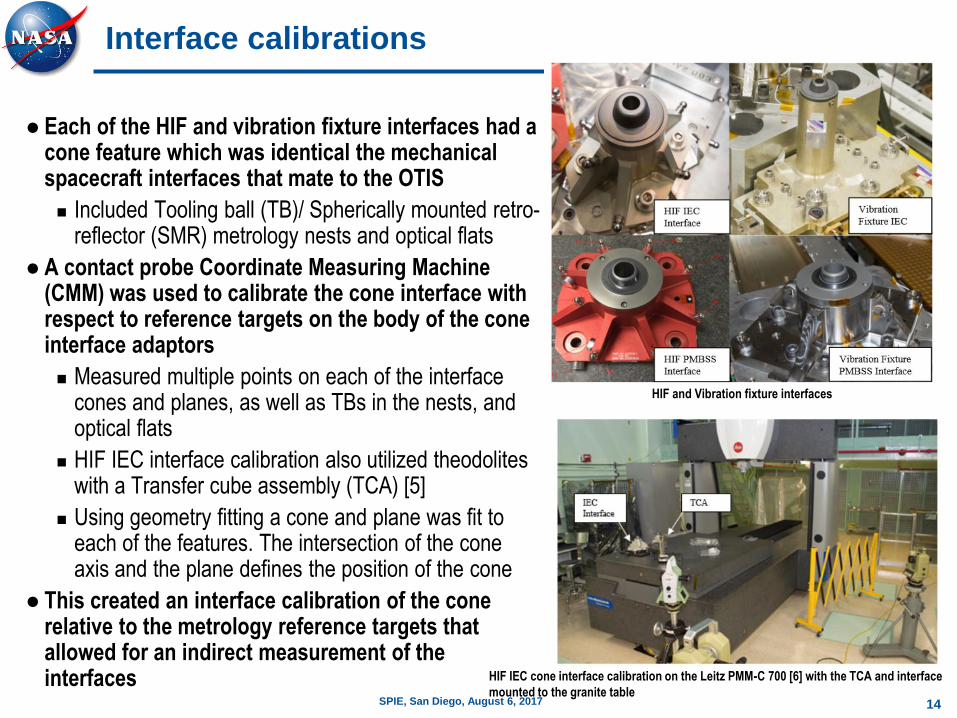
Each of the HIF and vibration fixture interfaces had a cone feature which was identical the mechanical spacecraft interfaces that mate to the OTIS
Included Tooling ball (TB)/ Spherically mounted retro-reflector (SMR) metrology nests and optical flats
A contact probe Coordinate Measuring Machine (CMM) was used to calibrate the cone interface with respect to reference targets on the body of the cone interface adaptors
Measured multiple points on each of the interface cones and planes, as well as TBs in the nests, and optical flats
HIF IEC interface calibration also utilized theodolites with a Transfer cube assembly (TCA) [5]
Using geometry fitting a cone and plane was fit to each of the features. The intersection of the cone axis and the plane defines the position of the cone
This created an interface calibration of the cone relative to the metrology reference targets that allowed for an indirect measurement of the interfaces HIF IEC cone interface calibration on the Leitz PMM-C 700 [6] with the TCA and interface
mounted to the granite table
HIF and Vibration fixture interfaces

15SPIE, San Diego, August 6, 2017
Interface calibration cross-check
A cross-check metrology was performed for each type of interface to verify the measurements of the CMM calibrations
LR used to measure the cones, metrology nests with tooling balls, and the optical flats
Cones measured using vision scan from multiple stations
Optical flats measured using the direct and through technique
The (SA) Unified Spatial Metrology Network (USMN) [7] process was used to bundle the LR stations
LR results compared to the CMM calibrations
Results showed an errors in one of the interface calibrations (2 mm in piston)
Probe diameter was not properly accounted for which could have resulted in a structural failure of OTIS during testing and transportation
Demonstrates the importance of additional verification measurements
HIF PMBSS interface laser radar vision scan

16SPIE, San Diego, August 6, 2017
HIF alignment
HIF was aligned using a combination of LR and Laser Tracker [8]
Interfaces aligned in angle and piston first, then position
Metrology nests measured with LR/LT
Interface calibration transformed to measured metrology nest locations
Interfaces shimmed and translated until aligned to the nominal prescription within specification
Interfaces distorted near the optical flats (optical flats not used)
Final calibration completed after alignment using laser radars
Each metrology nest measured from at least three stations
LR scanned cones directly as a cross-check
LR stations bundled using USMN function
Interface calibrations transformed to the USMN group using MCTU code
Alignment of the HIF met the nominal misalignment sub allocation
0.025mm in piston, 0.040mm in translation, and 30 arc-sec in angle
HIF alignment on the yellow IIS
17SPIE, San Diego, August 6, 2017
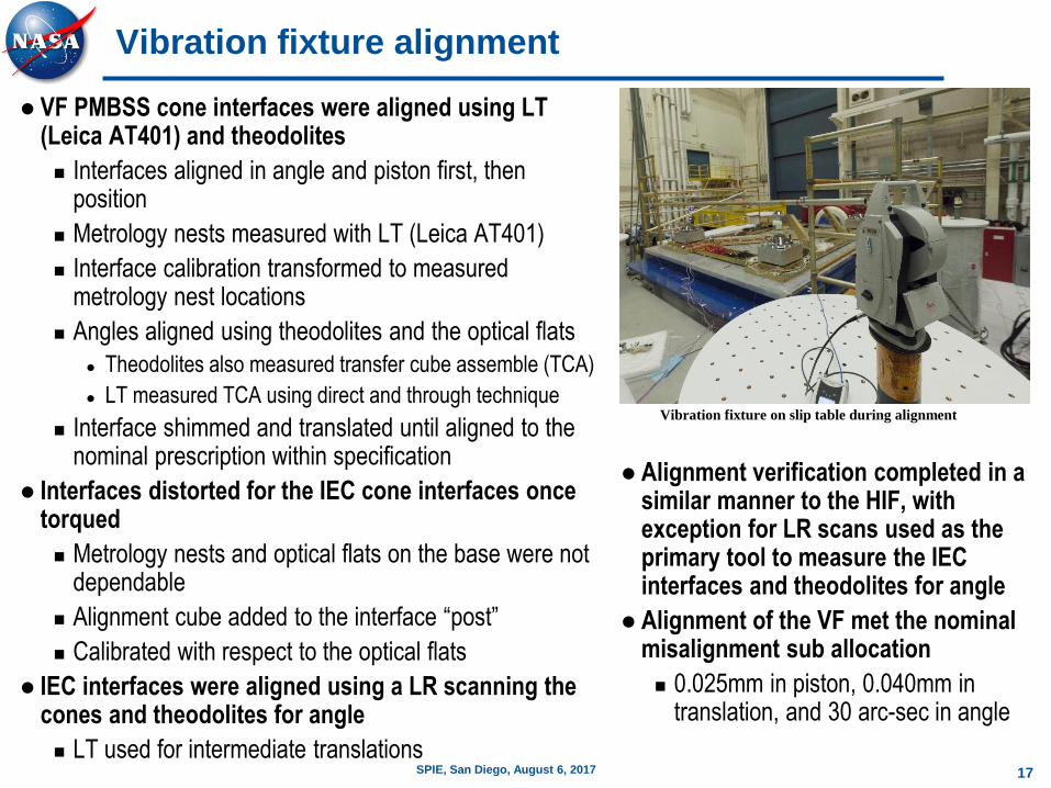
Vibration fixture alignment
VF PMBSS cone interfaces were aligned using LT (Leica AT401) and theodolites
Interfaces aligned in angle and piston first, then position
Metrology nests measured with LT (Leica AT401)
Interface calibration transformed to measured metrology nest locations
Angles aligned using theodolites and the optical flats
Theodolites also measured transfer cube assemble (TCA)
LT measured TCA using direct and through technique
Interface shimmed and translated until aligned to the nominal prescription within specification
Interfaces distorted for the IEC cone interfaces once torqued
Metrology nests and optical flats on the base were not dependable
Alignment cube added to the interface “post”
Calibrated with respect to the optical flats
IEC interfaces were aligned using a LR scanning the cones and theodolites for angle
LT used for intermediate translations
Alignment verification completed in a similar manner to the HIF, with exception for LR scans used as the primary tool to measure the IEC interfaces and theodolites for angle
Alignment of the VF met the nominal misalignment sub allocation
0.025mm in piston, 0.040mm in translation, and 30 arc-sec in angle
Vibration fixture on slip table during alignment

18SPIE, San Diego, August 6, 2017
Alignment verification
HIF and VF used on multiple structures and configurations though the integration and testing phase of the OTIS
Multiple alignment checks were performed to insure proper alignment to capture errors associate with these configurations
All verification metrology tests were performed in a similar manner
LR and/or LT measured each metrology nest from a minimum of three stations
The USMN process used to bundle the stations together
Interface calibrations transformed to the USMN group using MCTU code
HIF alignment verification

19SPIE, San Diego, August 6, 2017
Alignment verification: HIF proof test
The HIF was subjected to static load proof testing to ensure the HIF could survive the forces of OTIS during transportation
Metrology post proof test showed the interfaces translated ~0.150 mm
Shift between the HIF and cone interfaces was a result of the shear forces breaking the friction between the two parts
Once the load shear load was removed from the interfaces some of the misalignment induced was held in place by friction
Fasteners holding the interfaces to the HIF were released and re-torqued to the HIF, and the interface positions improved near the original alignment
Demonstrate importance of metrology before and after proof testing
Additional and larger pins were added to mitigate this problem
HIF static load proof test

20SPIE, San Diego, August 6, 2017
Alignment verification: HIF pre-OTIS integration
Alignment during integration of the OTIS was important to ensure any misalignment was not locked into the system once integrated
HIF alignment checked on the High Capacity Roll Over Fixture (HCROF) and the Space Telescope Transportation Air Road and Sea (STTARS) shipping container prior to OTIS integration
Shims added between the HIF and the mating interface to insure proper alignment in piston and angle
HCROF with OTIS and HIFHIF on STTARS

21SPIE, San Diego, August 6, 2017
Alignment verification: STTARS (for HIF) (1/2)
Another factor affecting the alignment of the HIF when on the STTARS, is distortion of the container during transportation
A displacement on one end of the STTARS can cause distortion at the STTARS HIF mating surfaces which results in alignment changes of the HIF cone interfaces
A metrology test was completed to characterize these affects and were correlated to a mechanical Finite Element Model (FEM)
Metrology targets were positioned at various points on the STTARS
Using a LT, displacements were applied using leveling jacks at the corners of the STTARS, then a metrology survey was completed
Metrology target locations on STTARS during distortion testingSTTARS HIF interface locations (16 bolt holes)

22SPIE, San Diego, August 6, 2017
Alignment verification: STTARS (for HIF) (2/2)
The test was completed with difference magnitudes of displacements at different corners
With the lid on and the lid off
Lid integration to STTARS
Leica AT401 positioned in the STTARS with the lid on, measuring the STTARS
HIF interfaces (View from the HIF interface end of STTARS)

23SPIE, San Diego, August 6, 2017
Alignment verification: Vibration fixture
temperature
The VF was aligned at a lower temperature than the operational temperature
The VF was warmed up to the 24C and measured in two different orientations on the slip table (Horizontal shaker)
Slip table warms up uniformly
VF fixture place on the head expander (vertical shaker)
Head expander does not warm up uniformly
The objective of the head expander metrology was to correlate the thermal model as the head expander temperature increases
The alignment deviations due to thermal variations on the head expander were accounted for in another error budget
Vibration fixture on the head expander thermal model

24SPIE, San Diego, August 6, 2017
Alignment verification: Vibration fixture proof
test
The vibration fixture, slip table, and head expander underwent proof testing using a mass simulator that interfaced with the vibration fixture PMBSS cones
Measurements were completed before and after each axis to insure the vibration fixture remained aligned
Vibration fixture with mass simulator on head expander for proof testing
25SPIE, San Diego, August 6, 2017
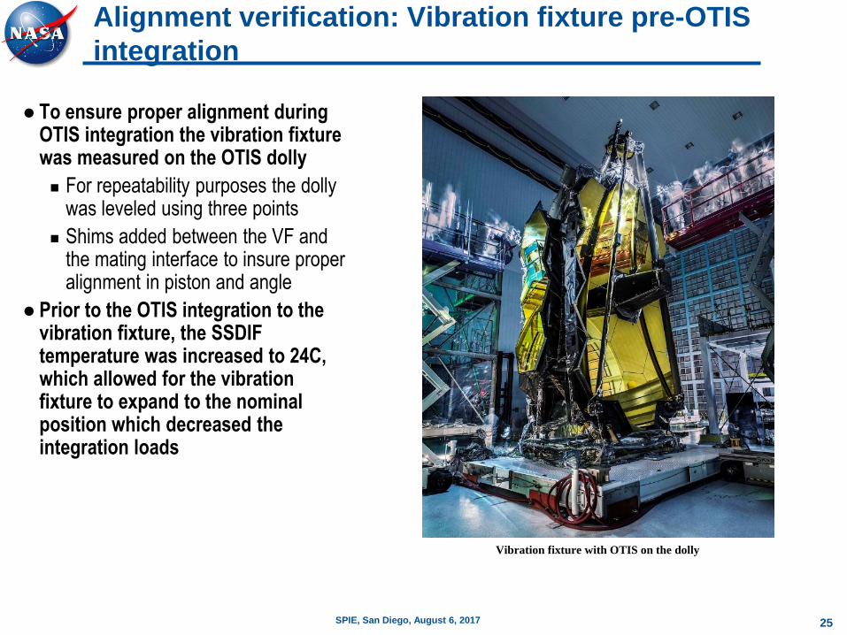
Alignment verification: Vibration fixture pre-OTIS
integration
To ensure proper alignment during OTIS integration the vibration fixture was measured on the OTIS dolly
For repeatability purposes the dolly was leveled using three points
Shims added between the VF and the mating interface to insure proper alignment in piston and angle
Prior to the OTIS integration to the vibration fixture, the SSDIF temperature was increased to 24C, which allowed for the vibration fixture to expand to the nominal position which decreased the integration loads
Vibration fixture with OTIS on the dolly

26SPIE, San Diego, August 6, 2017
Conclusion
Provided an overview of the alignment, testing, and verification processes used at the NASA GSFC in preparation of the HIF and vibration fixture for OTIS use
The OTIS successfully completed both vibration and acoustic testing on the vibration fixture, and the OTIS was successfully transported in STTARS to Johnson Space Center on the HIF for cryogenic testing prior to integration with the spacecraft and flight
27SPIE, San Diego, August 6, 2017
References
[1] A. Slotwinski and P. Blanckaert, “Frequency Modulated Coherent Laser Radar Technology,” Proceedings of the OPTIMESS2007 Workshop, Leuven, Belgium, May 28—30, 2007.
[2] New River Kinematics, Inc., Williamsburg, Va.
[3] Spatial Analyzer Users Manual, New River Kinematics, Williamsburg, v. 1.21.2008, page 150.
[4] J. Hayden, M. Khreishi, T. Hadjimichael, and R. Ohl, Monte Carlo Method for Uncertainty Propagation in JWST Metrology Databases, Coordinate Metrology Systems Conference, 2014.
[5] C. Aviado, J. Gill, K. Redman, and R. Ohl, Methods for correlating autocollimation of theodolites and coordinate metrology in spacecraft systems, Proc. SPIE 6273, 62733H, 2006
[6] Hexagon Metrology Inc., 250 Circuit Dr., North Kingstown, RI.
[7] S. Sandwith and R. Predmore, “Real-time 5-Micron Uncertainty with Laser Tracking Interferometer Systems using Weighted Trilateration,” Proc. SPIE.
[8] J. Burge, P. Su, C. Zhao, and T. Zobrist, “Use of a commercial laser tracker for optical alignment,” Optical System Alignment and Tolerancing, J. Sasian and M. Ruda, eds., Proc. SPIE 6676, SPIE Press, Bellingham, 66760E-1—12, 2007