


Languages
Pages
Legal


8/3/2019 Alex Kleiner- Spin stripes in nanotubes
http://slidepdf.com/reader/full/alex-kleiner-spin-stripes-in-nanotubes 1/4
a r
X i v : c o n d - m a t / 0 2 0 1
3 9 4 v 1
[ c o n d - m a t . m e s - h a l l ] 2 2 J a n 2 0 0 2
Spin stripes in nanotubes
Alex KleinerInstitute of Theoretical Physics
Chalmers University of Technology and G¨ oteborg University
S-412 96 G¨ oteborg, Sweden
It is shown here that electrons on the surface of a nanotube in a perpendicular magnetic fieldundergo spin-chirality separation along the circumference. Stripes of spin-polarization propagate
along the tube, with a spatial pattern that can be modulated by the electron filling.
The emerging field of spintronics opens a newparadigm of electronics based on the electron’s spinrather than charge [1]. The realization of a spin circuitrequires the generation, conduction and manipulation of spin currents. Recently, a spatial control of spin currentswas demonstrated by engineering a material with a spa-tially varying g-factor [2]. An alternative route wouldrequire a magnetic field with spatial variation on the
nanometer scale. Strong variations of the field can beachieved along the circumference of a nanotube subjectedto a uniform magnetic field, directed perpendicular to itsaxis. Here I suggest that a two dimensional electron gas(2DEG) rolled-up to a nanotube, may form spin-stripespropagating in alternating directions, as a function of thefilling. This applies to the conduction electrons in fieldssatisfying l R, where l is the Landau length
/|eB|
and R is the tube radius. At magnetic fields of B 10Tfor example, the radius should be R 8nm. Such sizesfrequently occur in
multi-wall carbon nanotubes (MWCNT) and in thenew class of recently produced rolled-up heterostructures
[3] [4]. The former, showed magneto-conductance fluc-tuations [5] [6], with varying interpretations in connec-tion to the diffusive [7] or ballistic [8] [9] nature of theMWCNT charge conductance. The spin conductance of a MWCNT however, was shown to be ballistic [10] overfairly large distances ( 130nm). On the other hand,the cylindrical heterostructures, made of silicon, silicon-germanium [4] or indium-gallium and indium-arsenic [3]have the advantage of controlled radiuses that can easilysatisfy l R, they can be made clean and without theproblem of unknown chirality and inter-shell coupling. Itwas found numerically [11] that a cylindrical spinless twodimensional electron gas (2DEG) under a perpendicular
magnetic field, forms Landau level like states at the topand bottom and chiral states, similar to the edge statesin the Hall bar, at the sides.The magnetic field B is taken here to be perpendicularto the surface at the lines x = 0 and x = πR here-after the north and south ‘poles’. The ‘equators’ are atx = πR/2 and x = 3πR/2, and states located anywhereabove or bellow the equators are called here ‘north’ or‘south’ states. The vector potential on the surface of the
tube is then A =
0, RB sin xR
, where (x, y) are the cir-
cumferential and axis directions of the tube, respectively.The Hamiltonian of a cylindrical 2DEG in this field is,
H = −2∂ 2x
2m∗+
2
2m∗
−i∂ y +
eRB
sin
x
R
2
+ µgs ·B
(1)
where m∗ is the effective mass, µ is the Bohr magneton,g is the gyro-magnetic factor and s is the spin operator.The longitudinal wave vector and spin are conserved sincethe Hamiltonian (1) does not contain the y coordinate norother spin operators and so the operators are replaced bytheir eigenvalues K y and ±gµB/2. The wave functionsfor the spin-up and spin-down particles are now ψ↑,↓ =eiKyyχ↑,↓(x). In units of E L/2, where E L = eB/m∗ isthe Landau level energy spacing, eq. (1) becomes thefollowing one dimensional Hamiltonian,
H = −l2∂ 2x +
K yl +
R
lsin
x
R
2
± gm∗
2me
(2)
The Hamiltonian (2) is a variant of Hill’s equation andcan be easily diagonalized numerically [11]. We wantto work in the regime where all the wave-functions areconfined in the circumferential direction. The weakestconfining potential in (2) is for K y = 0, which is a double-well with minima at the poles. This potential gives, toa linear order in x, Landau levels centered at the poles,with a spatial extension of l
√2n + 1, where n = 0, 1, 2 · ·.
Thus, the potential is always confining if R l√
2n + 1.The typical energy spectrum and probability distributionin this regime are shown in fig. (1).
1
8/3/2019 Alex Kleiner- Spin stripes in nanotubes
http://slidepdf.com/reader/full/alex-kleiner-spin-stripes-in-nanotubes 2/4
FIG. 1. Energy - Probability density phase space. (A): En-ergy spectrum of eq. (2), calculated numerically for R = 2.75l(R = 50nm and B = 2T), m∗ = me and g = 2. (B): Spatialprobability distribution along the circumferential coordinateof the lowest band (n = 0) states in the spectrum. Here theelectrons are well confined to the proximity of their potential
minima. At K y = 0 the potential in (2) is a double-well, oneat each pole. As |K y| increases, the two wells move closer to-wards one of the equators, and when |K y| ≥ R/l2 they mergeto one well, at the equator. This point is illustrated in (C)where we zoom on the potentials of two states, K y = 0.5R/l2
and 1.1R/l2 marked in (B) with white lines, having a dou-ble-well and a single well potentials, respectively.
The eigenfunctions (see fig. 1B) are confined in the cir-cumferential direction to their potential minima, depend-ing on K y. Since the Hamiltonian (2) is symmetric undera simultaneous sign inversion of x and K y, states withopposite K y are centered at opposite sides of the circum-ference [11], and states with K y = 0 are thus centered atthe poles. In the limit of a vanishing magnetic field, eachband is four-fold degenerate, i.e: twice due to spin degen-eracy and twice due to clock-wise and counter clock-wisepropagating modes. The magnetic field removes the fourdegeneracies, as shown in fig. (1A), except at K y ≈ 0,where a two-fold degeneracy remains. Higher magneticfields will not remove this degeneracy but rather increaseit, since here, in the confinement regime, the potential forK y ≈ 0 has two deep and isolated potential wells at thetwo poles. Only as K y → R/l2 the two potential wellsget close to each other across one of the equators for their
corresponding states to mix and remove the degeneracy.The total energy can be approximated analytically (seenote [12]) for small K y’s to give
E = ω(n +1
2) + 3λ
2mω
2
(2n2 + 2n + 1) ± ∆E n + 2s
(3)
where ω, λ and ∆E n are functions of K y, given in the note[12] and m ≡ me, having set for simplicity me = m∗ and
g = 2 in Eq. (2). The first two terms in Eq. ( 3) arethe energies of a harmonic oscillator with an anharmoniccorrection of a single-well potential V (K y) at a minima of Eq. (2). Since Eq. (2) has two minimas for |K y| < R/l2,these terms alone would give a two-fold degeneracy, with-out counting the spin. The third term largely removesthis degeneracy by mixing the north and south states,and the last term is the Zeeman splitting, with s =
±1
2.
Since the conduction properties are determined only byelectrons at the Fermi-energy, having the map betweenthe energy-momentum-spin state and the spatial distri-bution of that state (fig. 1), we can now find the spatialdistribution of the conduction electrons and their spins.The spin polarization density at a given Fermi-energy Eis defined asP (E, x) = (P ↑(E, x) − P ↓(E, x)) / (P ↑(E, x) + P ↓(E, x)),where the spin-up or spin-down polarization P ↑,↓(E, x) =
Kyg(E, K y)|χ↑,↓(E, K y, x)|2 factors the probabil-
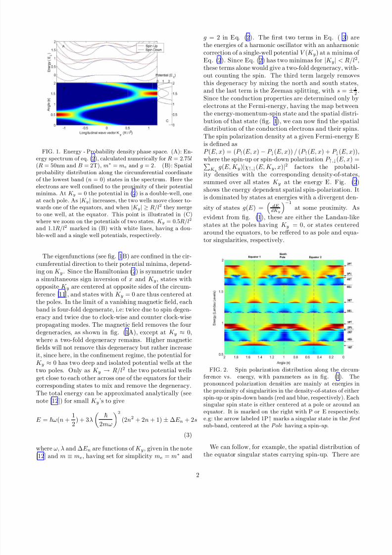
ity densities with the corresponding density-of-states,summed over all states K y at the energy E. Fig. (2)shows the energy dependent spatial spin-polarization. Itis dominated by states at energies with a divergent den-
sity of states g(E ) =dEdKy
−1
at some proximity. As
evident from fig. (1), these are either the Landau-likestates at the poles having K y = 0, or states centeredaround the equators, to be reffered to as pole and equa-tor singularities, respectively.
FIG. 2. Spin polarization distribution along the circum-ference vs. energy, with parameters as in fig. (1). Thepronounced polarization densities are mainly at energies in
the proximity of singularities in the density-of-states of eitherspin-up or spin-down bands (red and blue, respectively). Eachsingular spin state is either centered at a pole or around anequator. It is marked on the right with P or E respectively.e.g: the arrow labeled 1P↑ marks a singular state in the first
sub-band, centered at the Pole having a spin-up.
We can follow, for example, the spatial distribution of the equator singular states carrying spin-up. There are
2
8/3/2019 Alex Kleiner- Spin stripes in nanotubes
http://slidepdf.com/reader/full/alex-kleiner-spin-stripes-in-nanotubes 3/4
four such states in fig. (2), marked at the right as 1E ↑to 4E ↑, where the corresponding wave-functions aroundeach equator have, one to four peaks, respectively . Asimilar observation can be made for the pole singularities(marked with P in fig. 2), which are the Landau-likestates. Their energy can be found analytically by simplysetting K y = 0 in Eq. (3), giving
E n = E L(n + 12± 1
2) − E R(2n2 + 2n + 1), (4)
where the first term is the usual Zeeman split Landau lev-els and the second term is the curvature correction due tothe lateral energy, E R =
2
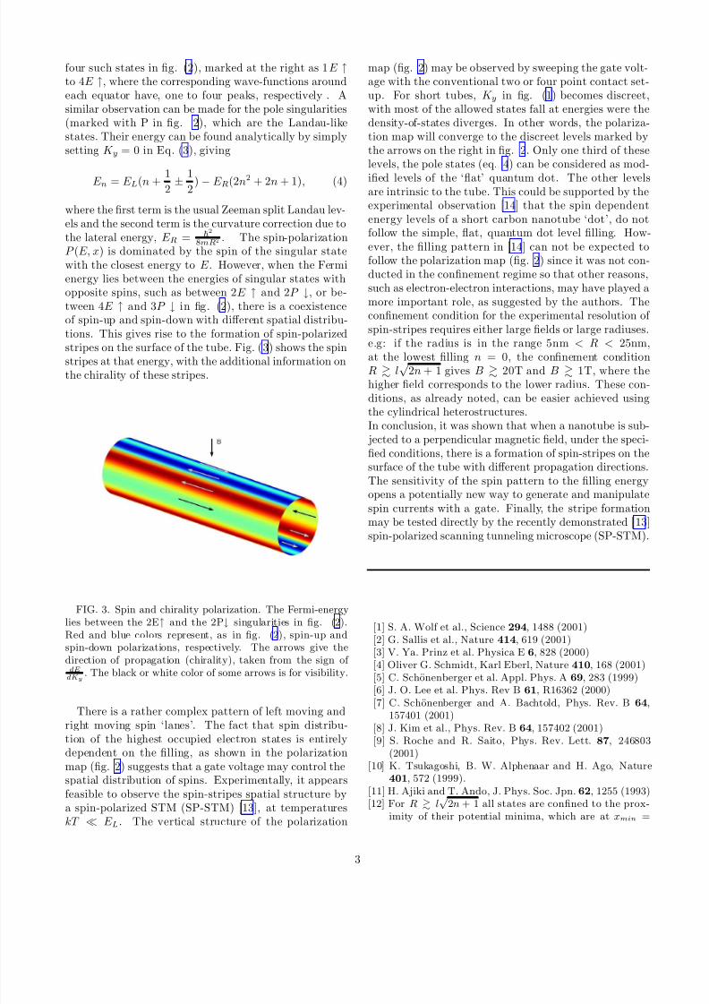
8mR2 . The spin-polarizationP (E, x) is dominated by the spin of the singular statewith the closest energy to E . However, when the Fermienergy lies between the energies of singular states withopposite spins, such as between 2E ↑ and 2P ↓, or be-tween 4E ↑ and 3P ↓ in fig. (2), there is a coexistenceof spin-up and spin-down with different spatial distribu-tions. This gives rise to the formation of spin-polarized
stripes on the surface of the tube. Fig. (3) shows the spinstripes at that energy, with the additional information onthe chirality of these stripes.
FIG. 3. Spin and chirality polarization. The Fermi-energylies between the 2E↑ and the 2P↓ singularities in fig. (2).Red and blue colors represent, as in fig. (2), spin-up andspin-down polarizations, respectively. The arrows give thedirection of propagation (chirality), taken from the sign of dEdKy
. The black or white color of some arrows is for visibility.
There is a rather complex pattern of left moving andright moving spin ‘lanes’. The fact that spin distribu-tion of the highest occupied electron states is entirelydependent on the filling, as shown in the polarizationmap (fig. 2) suggests that a gate voltage may control thespatial distribution of spins. Experimentally, it appearsfeasible to observe the spin-stripes spatial structure bya spin-polarized STM (SP-STM) [13], at temperatureskT ≪ E L. The vertical structure of the polarization
map (fig. 2) may be observed by sweeping the gate volt-age with the conventional two or four point contact set-up. For short tubes, K y in fig. (1) becomes discreet,with most of the allowed states fall at energies were thedensity-of-states diverges. In other words, the polariza-tion map will converge to the discreet levels marked bythe arrows on the right in fig. 2. Only one third of theselevels, the pole states (eq. 4) can be considered as mod-
ified levels of the ‘flat’ quantum dot. The other levelsare intrinsic to the tube. This could be supported by theexperimental observation [14] that the spin dependentenergy levels of a short carbon nanotube ‘dot’, do notfollow the simple, flat, quantum dot level filling. How-ever, the filling pattern in [14] can not be expected tofollow the polarization map (fig. 2) since it was not con-ducted in the confinement regime so that other reasons,such as electron-electron interactions, may have played amore important role, as suggested by the authors. Theconfinement condition for the experimental resolution of spin-stripes requires either large fields or large radiuses.e.g: if the radius is in the range 5nm < R < 25nm,at the lowest filling n = 0, the confinement conditionR l
√2n + 1 gives B 20T and B 1T, where the
higher field corresponds to the lower radius. These con-ditions, as already noted, can be easier achieved usingthe cylindrical heterostructures.In conclusion, it was shown that when a nanotube is sub-
jected to a perpendicular magnetic field, under the speci-fied conditions, there is a formation of spin-stripes on thesurface of the tube with different propagation directions.The sensitivity of the spin pattern to the filling energyopens a potentially new way to generate and manipulatespin currents with a gate. Finally, the stripe formation
may be tested directly by the recently demonstrated [13]spin-polarized scanning tunneling microscope (SP-STM).
[1] S. A. Wolf et al., Science 294, 1488 (2001)[2] G. Sallis et al., Nature 414, 619 (2001)[3] V. Ya. Prinz et al. Physica E 6, 828 (2000)[4] Oliver G. Schmidt, Karl Eberl, Nature 410, 168 (2001)[5] C. Schonenberger et al. Appl. Phys. A 69, 283 (1999)[6] J. O. Lee et al. Phys. Rev B 61, R16362 (2000)
[7] C. Schonenberger and A. Bachtold, Phys. Rev. B 64,157401 (2001)
[8] J. Kim et al., Phys. Rev. B 64, 157402 (2001)[9] S. Roche and R. Saito, Phys. Rev. Lett. 87, 246803
(2001)[10] K. Tsukagoshi, B. W. Alphenaar and H. Ago, Nature
401, 572 (1999).[11] H. Ajiki and T. Ando, J. Phys. Soc. Jpn. 62, 1255 (1993)[12] For R l
√2n + 1 all states are confined to the prox-
imity of their p otential minima, which are at xmin =
3

8/3/2019 Alex Kleiner- Spin stripes in nanotubes
http://slidepdf.com/reader/full/alex-kleiner-spin-stripes-in-nanotubes 4/4
R sin−1 |Ky|l2R
and πR − xmin for −R/l2 ≤ K y ≤ 0, andfor states with 0 ≤ K y ≤ R/l2 at 2πR − xmin and πR +xmin. The potential at a small distance ǫ from the min-ima can be expanded as V (K y, ǫ) = 1
2mω2ǫ2 + λǫ4, with
ω = 1R
El
m(R
2
l2−K 2y l2) and λ = El
24R4
7K 2y l
2 − 4R2
l2
.
The potential at |K y| ≤ R/l2 is a double-well, sym-metric about the equator, described by V (K y, ǫ) at thevicinity of its two minima xmin and πR
−xmin . De-
noting ψ1/2 for the two single well wave functions, thetotal wave function of state K y, to a zeroth order isΨs/a = 1√
2(ψ1 ± ψ2), where s/a corresponds to the
symmetric and antisymmetric product respectively. Dueto the non-zero tunneling probability across the equa-tor, the degeneracy of the symmetric and antisymmet-ric states is lifted. In the semi-classical approximation,
the energy is split by 42
mψ(xeq)ψ′(xeq) where ψ(xeq) and
ψ′(xeq) are either one of the single well wave functionsand their derivative, at the equator. Taking ψ(xeq) to bethe eigenfunctions of the harmonic part of the energy, the
first two energy splittings are ∆E 1 = 22
m1√ πa3
be−(b/a)2
and ∆E 2 = 42
m1√ πa5
b3e−(b/a)2 , where a
≡
mωand
b = R(π/2 − sin−1 Ky l2
R). This result agrees with the
numerics for |K y| R2l2
.[13] Heinze S. et al., Science 288, 1805 (2000)[14] Sander J. Tans et al., Nature 394, 761 (1998)
ACKNOWLEDGMENTS
I am indebted to Sebastian Eggert for many discus-sions and to Kim Jaeuk, Mikael Fogelstrom and PaataKakashvili for helpful comments on the manuscript.
4
Top Related