


Languages
Pages
Legal


THANK YOU
We appreciate the trust and confidence you have placed in Home Decorators Collection through the purchase of this fireplace console.
We strive to continually create quality products designed to enhance your home. Visit us online to see our full line of products available
for your home improvement needs. Thank you for choosing Home Decorators Collection!
Model # WSFP48ECHD-18 # WSFP48ECHD-18A # WSFP48ECHD-18B
OMSID # 207000449 OMSID # 207000508 OMSID # 207000499
ASSEMBLY INSTRUCTIONS
Bellevue Park 48 in. Media Console with Infrared Electric Fireplace
Questions, problems, missing parts? Before returning to the store,
call Home Decorators Collection Customer Service
8 a.m. - 7 p.m., EST, Monday-Friday
9 a.m. - 6 p.m., EST, Saturday
1-800-986-3460
HOMEDEPOT.COM/HOMEDECORATORS

2
Table of Contents
Table of Contents .................................................................. 2 Safety Information ................................................................ 2 Warranty .............................................................................. 2 Pre-Assembly ....................................................................... 2
Planning Assembly .......................................................... 2
Tools required ................................................................. 2
Hardware Included .......................................................... 3
Package Contents ........................................................... 4
Assembly.............................................................................. 5 Care and Maintenance ........................................................ 17
Safety Information
Please read and understand these instructions before
assembling and using this console. Save these instructions
for future reference.
MAXIMUM RECOMMENDED WEIGHT LOADS
WARNING: This unit is not intended for use with CRT TVs.
Use only with flat panel TVs and audio/video equipment
meeting recommended size and weight limits. Never use
with larger/heavier than recommended flat panel TVs or
equipment. To avoid instability, place flat panel TV in the
center of the unit; the base of the television must be able
to rest on the supporting surface of the unit without
over-hanging the edges. Improperly positioned flat panel
TVs, or flat panel TVs or other equipment that exceed
recommended size and weight limits could fall off or break
the unit, causing possible serious injury.
Warranty
We are confident that you will be delighted with this purchase. Should this product be defective in workmanship or materials, or
fail under normal use, we will repair or replace it for a period of up to one (1) year from date of purchase.
This warranty gives you specific rights and you may also have other rights which vary from state to state.
Contact the Customer Service Team at 1-800-986-3460 or visit www.HomeDepot.com/homedecorators.
Pre-Assembly
PLANNING ASSEMBLY Compare all parts with the Hardware Included and Package Contents list. If any part appears missing or damaged, do not
assemble this product and contact the Customer Service Team at 1-800-986-3460.
TOOLS REQUIRED
Phillips
screwdriver
(not provided)
Maximum load 22.6 kg / 50 lb
Place TV behind the stopper
Fits up to most 152.4 cm / 60 in. flat panel TVs
Maximum load 61.2 kg / 135 lb

3 HOMEDEPOT.COM/HOMEDECORATORS
Please contact 1-800-986-3460 for further assistance.
Pre-Assembly (continued)
HARDWARE INCLUDED
NOTE: Hardware not shown to actual size.
Part Description Quantity Part Description Quantity
AA Cam lock 32 + 1 extra MM Corner connector 12
BB Cam bolt 32 + 1 extra NN Door stopper 2
CC Long wood dowel 36 + 1 extra OO Knob 4
DD Short wood dowel 5 + 1 extra PP Knob bolt 4
EE Long wood screw 8 + 1 extra QQ Triangle metal plate 2
FF Medium wood screw 10 + 1 extra RR Floor leveler 2
GG Short wood screw 16 + 1 extra SS Acrylic stopper 1
HH Washer head screw 32 + 1 extra TT L-shaped metal brace 2
II Pan head screw 26 + 1 extra UU Glue 1
JJ Cam lock cover 20 + 1 extra VV Touch-up pen
(not included for WSFP48ECHD-18B) 1
KK Shelf pin 8 + 1 extra WW Tipping restraint hardware kit 2
LL Straight metal plate 2
LL MM NN OO PP QQ RR
UU TT
SS
AA BB CC DD EE FF GG HH II JJ KK
VV WW

4
Pre-Assembly (continued)
PACKAGE CONTENTS
Part Description Quantity Part Description Quantity
A Top panel 1 M Center front molding 1
B Center shelf 1 N Adjustable shelf 2
C Bottom panel 1 O Left lower side panel 1
D Upper back panel 1 P Right lower side panel 1
E Bottom back stretcher 1 Q Left lower partition panel 1
F Bottom front stretcher 1 R Right lower partition panel 1
G Bottom front molding 1 S Lower back panel 2
H Upper side panel 2 T Door 2
I Upper partition panel 1 U Middle stile 2
J Bottom left molding 1 Fireplace insert 1
K Bottom right molding 1 Remote control with battery 1
L Center crossbar 1
A
B
C
D
E
F
G
H I J K
LM
N
O P Q R
S T U
5 HOMEDEPOT.COM/HOMEDECORATORS
Please contact 1-800-986-3460 for further assistance.
Assembly
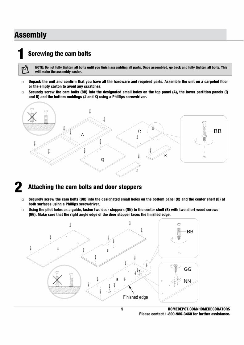
1 Screwing the cam bolts
NOTE: Do not fully tighten all bolts until you finish assembling all parts. Once assembled, go back and fully tighten all bolts. This
will make the assembly easier.
□ Unpack the unit and confirm that you have all the hardware and required parts. Assemble the unit on a carpeted floor
or the empty carton to avoid any scratches.
□ Securely screw the cam bolts (BB) into the designated small holes on the top panel (A), the lower partition panels (Q
and R) and the bottom moldings (J and K) using a Phillips screwdriver.
2 Attaching the cam bolts and door stoppers
□ Securely screw the cam bolts (BB) into the designated small holes on the bottom panel (C) and the center shelf (B) at
both surfaces using a Phillips screwdriver.
□ Using the pilot holes as a guide, fasten two door stoppers (NN) to the center shelf (B) with two short wood screws
(GG). Make sure that the right angle edge of the door stopper faces the finished edge.
B
B
BB
GG
NN
C
BBA
Q
R
K
J
6
Assembly (continued)
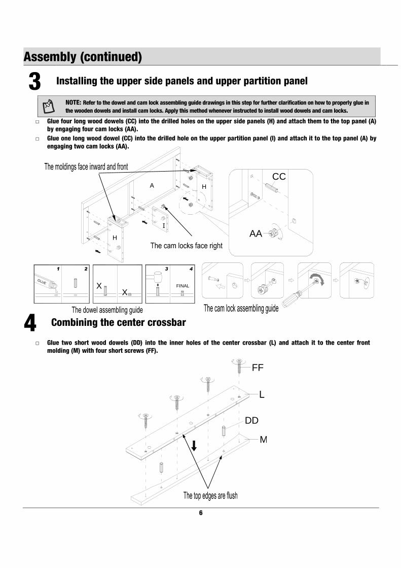
3 Installing the upper side panels and upper partition panel
NOTE: Refer to the dowel and cam lock assembling guide drawings in this step for further clarification on how to properly glue in
the wooden dowels and install cam locks. Apply this method whenever instructed to install wood dowels and cam locks.
□ Glue four long wood dowels (CC) into the drilled holes on the upper side panels (H) and attach them to the top panel (A)
by engaging four cam locks (AA).
□ Glue one long wood dowel (CC) into the drilled hole on the upper partition panel (I) and attach it to the top panel (A) by
engaging two cam locks (AA).
4 Combining the center crossbar
□ Glue two short wood dowels (DD) into the inner holes of the center crossbar (L) and attach it to the center front
molding (M) with four short screws (FF).
A
H
H
I
AA
CC
DD
M
L
FF
GLUE
XX
FINAL
1 2 43
7 HOMEDEPOT.COM/HOMEDECORATORS
Please contact 1-800-986-3460 for further assistance.
Assembly (continued)
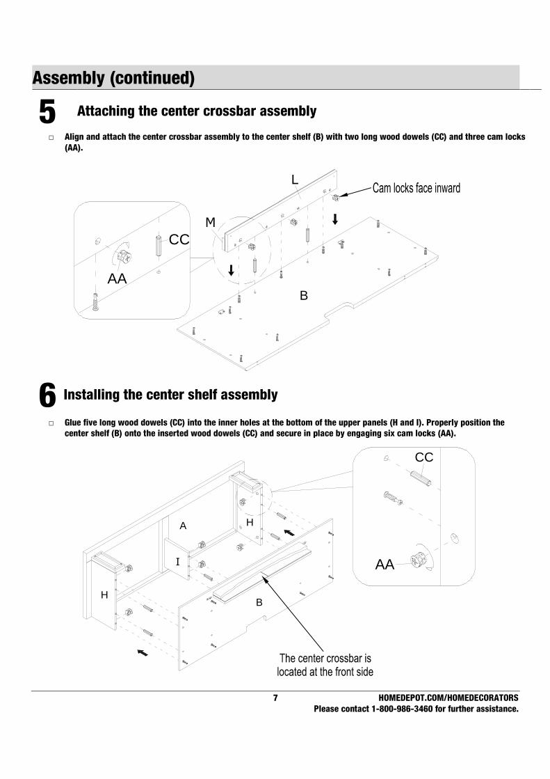
5 Attaching the center crossbar assembly
□ Align and attach the center crossbar assembly to the center shelf (B) with two long wood dowels (CC) and three cam locks
(AA).
6 Installing the center shelf assembly
□ Glue five long wood dowels (CC) into the inner holes at the bottom of the upper panels (H and I). Properly position the
center shelf (B) onto the inserted wood dowels (CC) and secure in place by engaging six cam locks (AA).
CC
AA
BH
I
HA
AA
CC
L
M
B

8
Assembly (continued)
7 Attaching the middle stiles
□ Fasten one middle stile (U) to the left lower partition panel (Q) with two long wood dowels (CC) and two cam locks
(AA).
□ Repeat the same procedure to combine the other middle stile (U) and right lower partition panel (R) together.
8 Installing the lower side and partition panels
□ Glue four long wood dowels (CC) into the top inner holes of left lower side and partition panels (O and Q).
□ Align the large holes on the center shelf (B) with the inserted wood dowels (CC) and press them together. Secure the
lower side and partition panels (O and Q) in place by engaging four cam locks (AA).
□ Repeat the same procedure to attach the right lower side and partition panels (P and R) at the opposite end.
B
O
P
Q
R
AA
CC
RQ
U
U
AA
CC
9 HOMEDEPOT.COM/HOMEDECORATORS
Please contact 1-800-986-3460 for further assistance.
Assembly (continued)
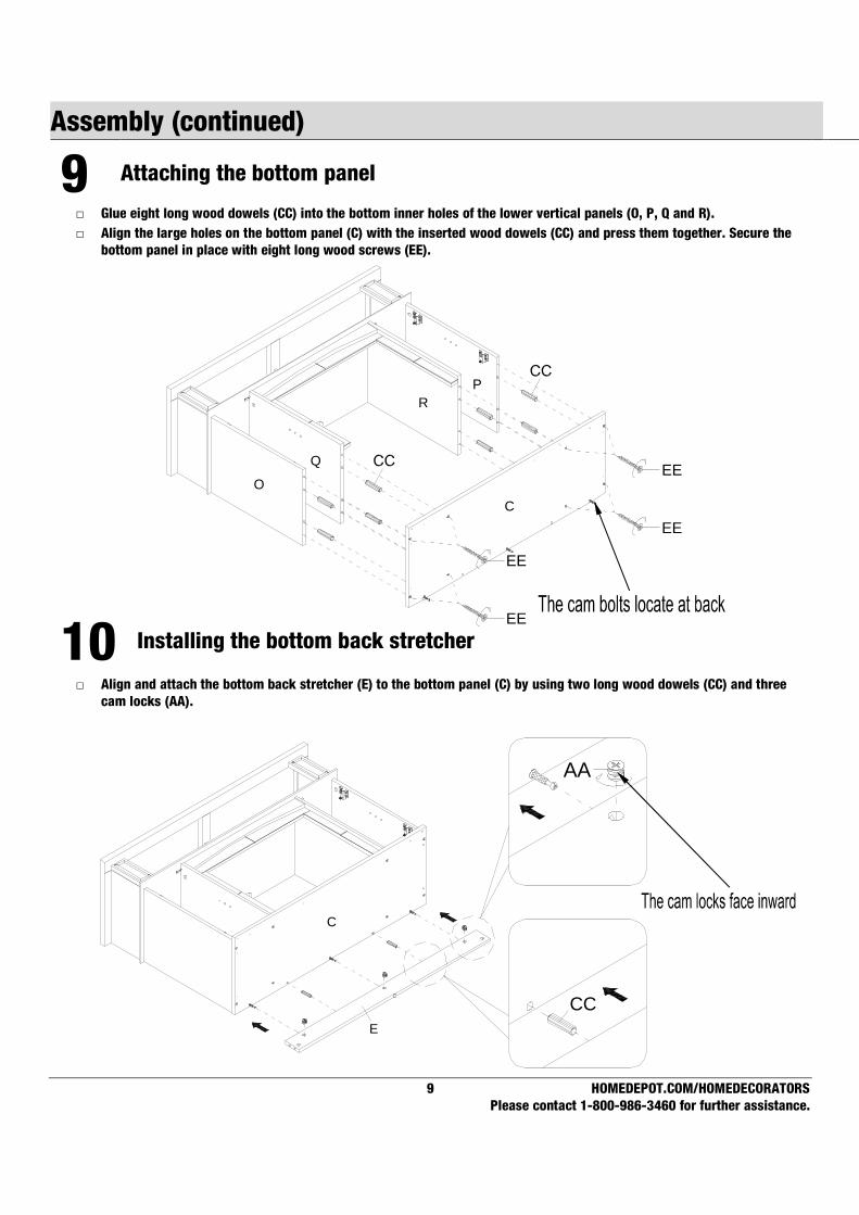
9 Attaching the bottom panel
□ Glue eight long wood dowels (CC) into the bottom inner holes of the lower vertical panels (O, P, Q and R).
□ Align the large holes on the bottom panel (C) with the inserted wood dowels (CC) and press them together. Secure the
bottom panel in place with eight long wood screws (EE).
10 Installing the bottom back stretcher
□ Align and attach the bottom back stretcher (E) to the bottom panel (C) by using two long wood dowels (CC) and three
cam locks (AA).
EE
EE
EE
EEO
P
Q
R
C
C
E
AA
CC

10
Assembly (continued)
11 Attaching the bottom moldings
□ Align and attach the bottom left molding (J) to the bottom back stretcher (E) with one long wood dowel (CC) and one
cam lock (AA).
□ Using the pilot holes as a guide, fasten two corner connectors (MM) at the bottom joints between the bottom left
molding (J) and the bottom panel (C) using four pan head screws (II). Tighten all screws with a Phillips screwdriver.
□ Repeat the same procedure to attach the bottom right molding (K) at the opposite end.
12 Combining the bottom front stretcher and molding
□ Glue three short wood dowels (DD) into the inner holes of the bottom back stretcher (F) and attach it to the bottom
front molding (G) with six medium wood screws (FF).
J
K
E
C
MM
II
CC
AA
FF
FF
FF G
DD
F

11 HOMEDEPOT.COM/HOMEDECORATORS
Please contact 1-800-986-3460 for further assistance.
Assembly (continued)
13 Attaching the bottom front molding assembly □ Align and attach the assembled bottom front molding (G) to the bottom side moldings (J and K) and the bottom panel
(C). Using the pilot holes as guide, fasten eight corner connectors (MM) at the bottom joints using two pan head
screws (II) per connector. Tighten all screws with a Phillips screwdriver.
14 Installing the triangle metal plates
□ Using the pilot holes as a guide, fasten two triangle metal plates (QQ) at the bottom joints between the bottom front
molding (G) and side moldings (J and K) using four short wood screws (GG) per plate.
G
C
J
K
II
MMMM
MMF
II
II
C
G
J
K
GG

12
Assembly (continued)
15 Screwing the floor levelers
□ Tightly screw two floor levelers (RR) into the installed triangle metal plates (QQ).
16 Installing the metal plate
□ Flip the assembled unit around at its front edges. Secure the middle crossbar (L) to the middle stiles (U) by attaching
two metal plates (LL) at the joints, using two short wood screws (GG) in each, as shown.
GG
LL
UL
U
C
G
J
K RR
RR

13 HOMEDEPOT.COM/HOMEDECORATORS
Please contact 1-800-986-3460 for further assistance.
Assembly (continued)
17 Attaching the back panels
□ Pick up the upper back panel (D) and align the pre-drilled holes against the upper long edge with the pilot holes on the
back stretcher of the top panel (A). Attach the back panel (D) in place using the provided washer head screws (HH).
□ Align and attach two lower back panels (S) to the lower side panels and partition panels (O, P, Q and R) with the
provided washer head screws (HH).
18 Installing the doors
□ Stand the unit upright.
□ Attach two knobs (OO) to the front side of each door (T) with the knob bolts (PP).
□ Pick up one door (T) and attach the extended hinge arms to the hinge bases installed on left side panel (O). Loosen
the bolt on the back of hinge base for an easy fit. Align and insert the “U” slot on the hinge arm under the bolt head
on the back of the hinge base. Make sure that both door hinges engage and function properly. Tighten the bolt on the
hinge base to lock the hinges in place.
□ Repeat the same procedure to attach the other door (T) at the opposite side.
□ Open and close the doors to make sure they are aligned and shut correctly. If necessary, adjust the screws for a
good fit. Refer to the hinge sticker on the door for adjustment.
OO
PP
OO
PP
T
1
T
T
O
P
HH
D
S
S
H
P
QB
C
UP
UP

14
Assembly (continued)
19 Attaching the adjustable shelves and cam lock covers
□ Insert four shelf pins (KK) into the desired holes inside each side compartment. Tilt and rest the adjustable shelves
(N) onto the shelf pins (KK).
□ Plug the cam lock covers (JJ) onto the visible cams locks to conceal the cams.
20 Installing the fireplace insert
□ Lift the fireplace insert carefully into the back of the assembled mantel and center it in the opening. DO NOT drag the
insert across the bottom panel (C) as it may scratch the unit.
O
P
RQ
N
N
KK
KK
JJ
ElectricFirebox
C

15 HOMEDEPOT.COM/HOMEDECORATORS
Please contact 1-800-986-3460 for further assistance.
Assembly (continued)
21 Attaching the L-shaped metal braces
□ Using the pilot holes as a guide, align and attach two L-shaped metal braces (TT) to the bottom panel (C) by screwing
one pan head screw (II) in each.
II
TT
16
Assembly (continued)
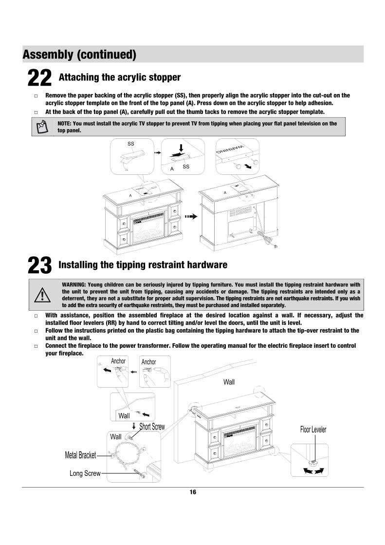
22 Attaching the acrylic stopper
□ Remove the paper backing of the acrylic stopper (SS), then properly align the acrylic stopper into the cut-out on the
acrylic stopper template on the front of the top panel (A). Press down on the acrylic stopper to help adhesion.
□ At the back of the top panel (A), carefully pull out the thumb tacks to remove the acrylic stopper template.
NOTE: You must install the acrylic TV stopper to prevent TV from tipping when placing your flat panel television on the
top panel.
23 Installing the tipping restraint hardware
WARNING: Young children can be seriously injured by tipping furniture. You must install the tipping restraint hardware with
the unit to prevent the unit from tipping, causing any accidents or damage. The tipping restraints are intended only as a
deterrent, they are not a substitute for proper adult supervision. The tipping restraints are not earthquake restraints. If you wish
to add the extra security of earthquake restraints, they must be purchased and installed separately.
□ With assistance, position the assembled fireplace at the desired location against a wall. If necessary, adjust the
installed floor levelers (RR) by hand to correct tilting and/or level the doors, until the unit is level.
□ Follow the instructions printed on the plastic bag containing the tipping hardware to attach the tip-over restraint to the
unit and the wall.
□ Connect the fireplace to the power transformer. Follow the operating manual for the electric fireplace insert to control
your fireplace.
AA

17 HOMEDEPOT.COM/HOMEDECORATORS
Please contact 1-800-986-3460 for further assistance.
Care and Maintenance
A Touch-up Pen has been provided to repair any small nicks or scratches that may occur during assembly or shipping.
To clean and care for your furniture:
□ Use a soft, clean cloth that will not scratch the surface when dusting.
□ Use of furniture polishes is not necessary. Should you choose to use polishes, test first in an inconspicuous area.
□ Using solvents of any kind on your furniture may damage the finish.
□ Never use water to clean your furniture as it may cause damage to the finish.
□ Always use coasters under beverage glasses and flowerpots.
□ Liquid spills should be removed immediately. Using a soft clean cloth, blot the spill gently. Avoid rubbing.
□ Always use protective pads under hot dishes and plates. Heat can cause chemical changes that may create spotting
within the furniture finish.
□ Stains or marks from crayons or ink markers will be difficult to remove.
□ In the event that your furniture is stained or otherwise damaged during use, we recommend that you call a professional
to repair your furniture.
□ Check bolts/screws periodically and tighten them if necessary.
CARING FOR WOOD FURNITURE
It is best to keep your furniture in a climate-controlled environment. Extreme temperature and humidity changes can cause
fading, warping, shrinking and splitting of wood. It is advised to keep furniture away from direct sunlight as sun may damage
the finish.
Proper care and cleaning at home will extend the life of your purchase. Following these important and helpful tips will enhance
your furniture as it ages.
CLEANING THE FIREPLACE TRIM
Clean the metal trim using a soft cloth, slightly dampened with citrus oil based product and buff with a clean soft cloth. DO NOT
use brass polish or household cleaners as these products will damage the metal trim. Citrus oil based products can be obtained
at supermarkets or hardware stores.

Questions, problems, missing parts? Before returning to the store,
call Home Decorators Collection Customer Service
8 a.m. - 7 p.m., EST, Monday-Friday
9 a.m. - 6 p.m., EST, Saturday
1-800-986-3460
HOMEDEPOT.COM/HOMEDECORATORS
Top Related