


Languages
Pages
Legal


Advanced Small Modular Reactors Materials Activities
William Corwin
Department of Energy Office of Nuclear Energy
Office of Advanced Reactor Technologies
DOE-NE Materials Coordination Webinar July 30, 2013

SMR Materials Work Packages Address Several Small Advanced Reactor Systems
WP No. SMR R&D Program WBS Element Description
Remarks
SR-13IN060106 High Temperature Design Methodology - INL VHTR, Alloy 617 Code Case (with additional funding from NGNP)
SR-13OR060107 High Temperature Design Methodology - ORNL VHTR, Alloy 617 Code Case
SR-13AN060101 Materials for Advanced SMR Concepts - ANL Design methodology, SFR materials
SR-13OR060103 Materials for Advanced SMR Concepts - ORNL Design methodology, SFR materials
SR-13LA060102 Materials and Component Studies for Lead-Bismuth SMR Concepts - LANL
LBE-FR, Delta Loop compatibility testing
SR-13OR060108 SiC-SiC Composite Code Development - ORNL VHTR, FHR, SFR
SR-13OR060105 Design and Codification Basis for SMR-Specific Materials - ORNL
Gen IV Materials Handbook
SR-13PN060104 Material Issues for SMR Operational Environments - PNNL
Integral PWR

ASME Code Qualification Activities Address Multiple Reactor Systems
SMR Program Activities to address key long-term design needs for application of advanced materials (ORNL, ANL & INL)
High temperature design methodology is an enabling reactor technology
– Removal of unnecessary conservatism in inelastic design methodology could lead to more flexibility in construction and operation of advanced SMRs
– Gaining mechanistic understanding of long-term degradation mechanisms such as creep & creep-fatigue damage and thermal aging could provide guidance on extrapolation of accelerated time-at-temperature design data for 60-year design life, and beyond, with higher confidence
Materials to be addressed – Existing ASME Code materials; 9Cr-1Mo-V steel (Grade 91), 316 stainless
steel – Methodologies applicable to advanced materials being studied under
Advanced Reactor Concepts (ARC) Program, optimized Grade 92 (with thermo-mechanical treatment) and Alloy 709 austenitic stainless steel, and Next Generation Nuclear Plant (NGNP) Program, Alloy 617

Cyclic Softening Impacts Grade 91 and Grade 92 Ferritic-Martensitic Steels
A cyclic softening curve can be divided into three stages: primary, secondary, and tertiary, similar to a creep curve. In the secondary stage, the cyclic stress follows a linear relationship with cycles, and thus a steady-state cyclic softening rate can be obtained.
The cyclic softening rate of G91 is significantly higher than that of optimized G92 under a given creep-fatigue test condition with a strong dependence on the waveform and hold time.
An improved Cyclic Softening Model is established by combining the thermally-activated rate equation and steady-state cyclic softening rates.
Damage from Sequential and Concurrent Creep-Fatigue Tests Was Compared
Sequential and concurrent creep-fatigue tests were conducted to understand the effect of cyclic softening on creep and fatigue properties, and creep-fatigue interaction mechanisms.
Pure Fatigue Fatigue + Creep
Creep + Fatigue Strain-controlled/Load-controlled Creep-Fatigue
Creep-Fatigue Interactions in Grade 91 and Grade 92 Ferritic-Martensitic Steels
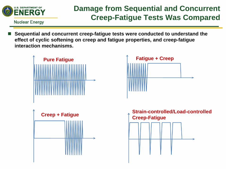
Sequential vs concurrent creep-fatigue tests showed that the synergistic interaction of creep and fatigue is most pronounced in load-controlled creep-fatigue loading conditions, followed next by strain-controlled C-F loading. Creep deformation and damage processes are accelerated by periodic cyclic loading.
A two-step, sequential loading of creep and fatigue has either no effect or a beneficial effect on the creep or fatigue life. Therefore, sequential creep and fatigue tests cannot be used to simulate synergistic effects of creep-fatigue interaction on the life of G91 steel.
The FY13 NEUP Program will investigate other innovative experimental approaches for C-F damage predominantly in the creep domain.
Crack Initiation & Propagation Independently Affect Life Predictions in Gr91
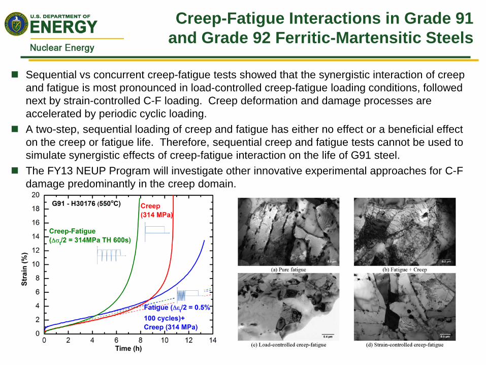
Crack initiation life follows a power law relationship with the cyclic softening rate. This correlation is independent of metallurgical and mechanical variables, implying importance of cyclic deformation in crack initiation.
Grain boundary cavitation observed in G91, in contrast to literature. While creep microcracks initiated primarily at the prior γ grain boundaries in G91, the cavitation sites in G92 are more diversified, possibly explaining better creep- and creep-fatigue-resistance of optimized G92 than G91.
Creep cracks grow along the loading direction. Fatigue cracks advance in the direction perpendicular to the loading direction. Oxidation plays an important role in fatigue crack initiation and propagation.
Crack initiation and crack propagation should be separately considered and modeled, and creep-fatigue-oxidation interaction mechanisms should be considered in both crack initiation and propagation.
Load
ing
dire
ctio
n
Creep Damage
Fatigue Damage
Aging Affects Transition Behavior and Ductile Fracture Toughness of Grade 91
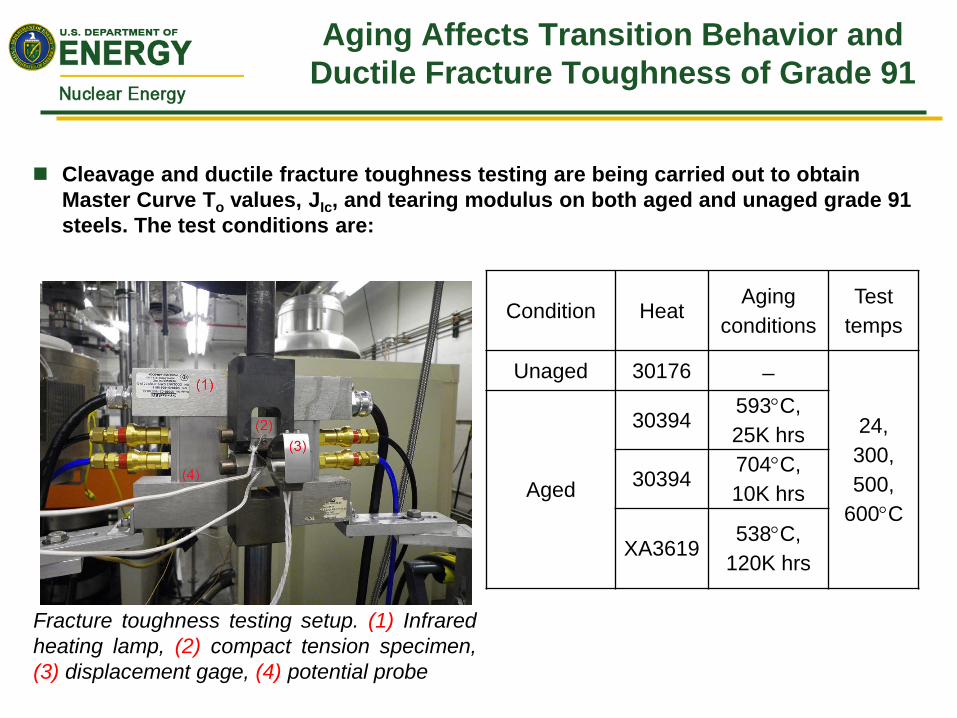
Cleavage and ductile fracture toughness testing are being carried out to obtain Master Curve To values, JIc, and tearing modulus on both aged and unaged grade 91 steels. The test conditions are:
Condition Heat Aging
conditions Test
temps
Unaged 30176 ̶
24, 300, 500,
600°C Aged
30394 593°C, 25K hrs
30394 704°C, 10K hrs
XA3619 538°C,
120K hrs
Fracture toughness testing setup. (1) Infrared heating lamp, (2) compact tension specimen, (3) displacement gage, (4) potential probe

Low Temperature Aging Is More Harmful for Grade 91
Material aged at 704C/10K h exhibited better fracture toughness than the material aged at 593C/25K , in agreement with Charpy and transition temperature test results
Long-term aging at 538C/120K significantly reduced fracture toughness (Jq) and tearing modulus of Grade 91, which was affected by test temperature
In general, aging at high temperatures slightly improves ductile fracture toughness similar to CVN USE results, but aging at lower temperatures reduces toughness
Microstructure-Fracture Properties Correlation Support Aging Models
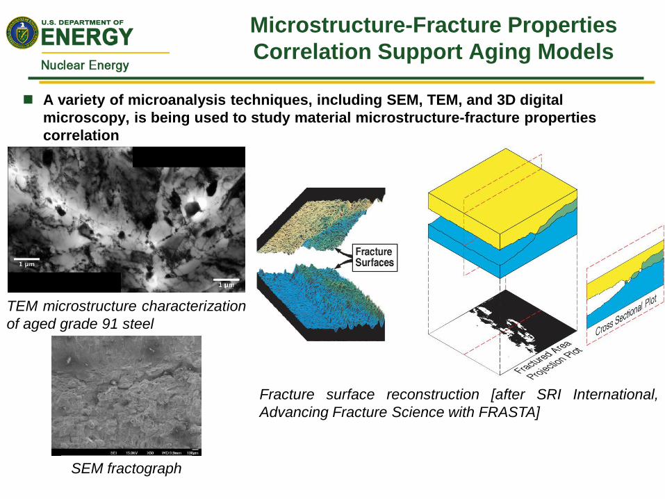
A variety of microanalysis techniques, including SEM, TEM, and 3D digital microscopy, is being used to study material microstructure-fracture properties correlation
Fracture surface reconstruction [after SRI International, Advancing Fracture Science with FRASTA]
TEM microstructure characterization of aged grade 91 steel
SEM fractograph
Mechanism-Based Creep Fracture Modeling Used for Long-Life Predictions
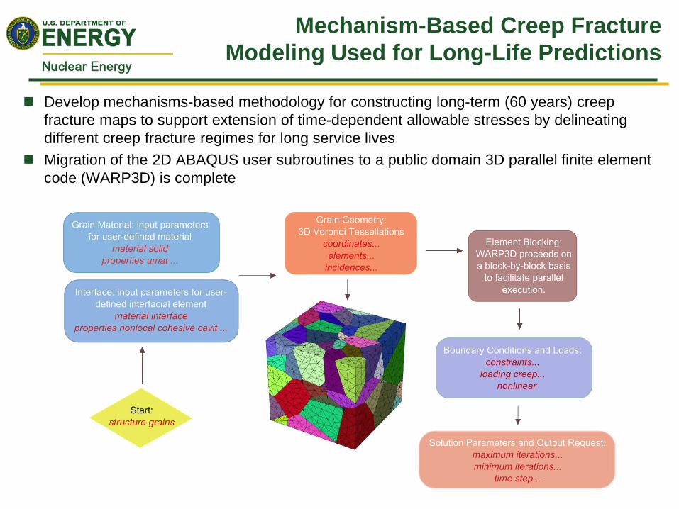
Develop mechanisms-based methodology for constructing long-term (60 years) creep fracture maps to support extension of time-dependent allowable stresses by delineating different creep fracture regimes for long service lives
Migration of the 2D ABAQUS user subroutines to a public domain 3D parallel finite element code (WARP3D) is complete

LANL Delta Loop Being Used to Evaluate Materials for LBE Service
12
Design/Performance : * Up to 2 m/s in 2.54 cm diameter
~ 3 m long test section
* Up to 100°C ∆T between heater section and heat exchanger exit
* Up to 550°C operation in the test section
* Capable of free convection flow * All 316L construction * Gas injection system for oxygen
control
DELTA isometric view

DELTA 3000 hr Corrosion Test Plan
13
* Corrosion resistance: Exposure up to 3000h in flowing LBE at 500oC
and Oxygen concentration 10-6-10-8 wt%.
* Flow-rate resistance: LBE velocities up to 3.5 m/s * Total of 144 specimens tested
Thin test coupons are placed in a cylindrical holder that is lowered into the test section.
Goal: Understand flow velocity and high-temperature effects on LBE steel corrosion properties for exposure times >2000h
Canister loaded with 48 specimens
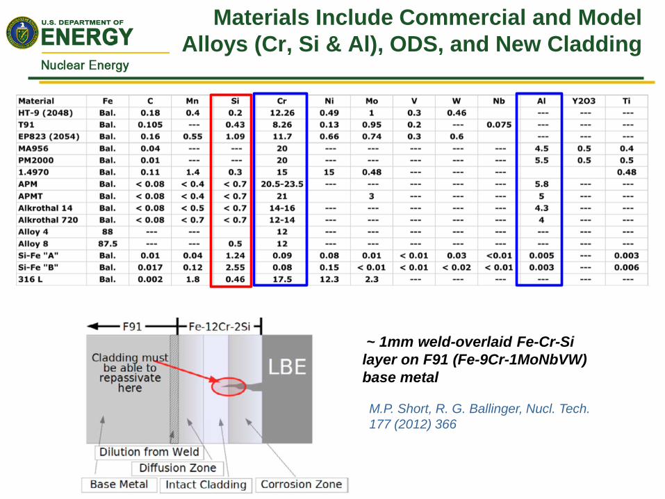
Materials Include Commercial and Model Alloys (Cr, Si & Al), ODS, and New Cladding
~ 1mm weld-overlaid Fe-Cr-Si layer on F91 (Fe-9Cr-1MoNbVW) base metal
M.P. Short, R. G. Ballinger, Nucl. Tech. 177 (2012) 366

Flow conditions T [C] 488 Flow-rate [m3/h] 5.3 Velocity [m/s] 3.5 Oxygen concentration [wt%]
2.3 x 10⁻⁵
Samples Oxide thickness
APM 1 μm APMT 5 μm MA956 5 μm EP823 10 μm G92 10 μm HT-9 20 μm ALK14 15 μm ALK720 10 μm PM2000 1 μm
Initial LBE Flow Corrosion Results Rank Test Materials
•Thinnest oxide layer observed with Al-added material (e.g MA-956, Kanthal alloys) •Double layer oxide observed with high Cr materials •Addition of Si to materials help oxide stability •Oxide layer appears stable at high flow rates (3.5 m/s)
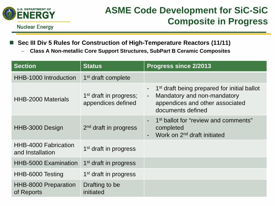
ASME Code Development for SiC-SiC Composite in Progress
Sec III Div 5 Rules for Construction of High-Temperature Reactors (11/11) – Class A Non-metallic Core Support Structures, SubPart B Ceramic Composites
Section Status Progress since 2/2013
HHB-1000 Introduction 1st draft complete
HHB-2000 Materials 1st draft in progress; appendices defined
- 1st draft being prepared for initial ballot - Mandatory and non-mandatory
appendices and other associated documents defined
HHB-3000 Design 2nd draft in progress - 1st ballot for “review and comments”
completed - Work on 2nd draft initiated
HHB-4000 Fabrication and Installation 1st draft in progress
HHB-5000 Examination 1st draft in progress
HHB-6000 Testing 1st draft in progress
HHB-8000 Preparation of Reports
Drafting to be initiated
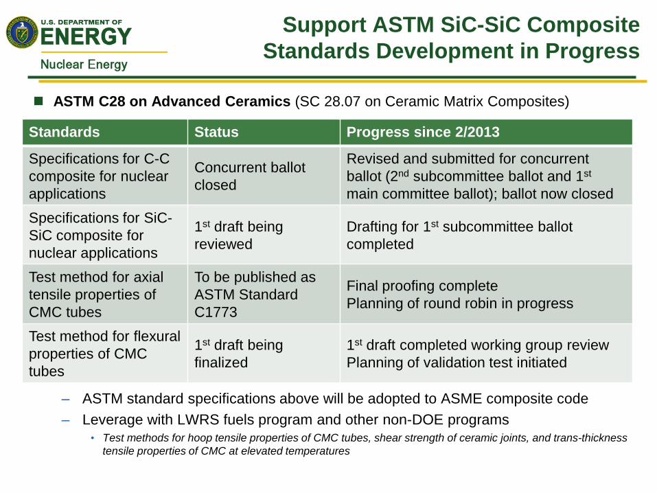
Support ASTM SiC-SiC Composite Standards Development in Progress
ASTM C28 on Advanced Ceramics (SC 28.07 on Ceramic Matrix Composites)
– ASTM standard specifications above will be adopted to ASME composite code – Leverage with LWRS fuels program and other non-DOE programs
• Test methods for hoop tensile properties of CMC tubes, shear strength of ceramic joints, and trans-thickness tensile properties of CMC at elevated temperatures
Standards Status Progress since 2/2013
Specifications for C-C composite for nuclear applications
Concurrent ballot closed
Revised and submitted for concurrent ballot (2nd subcommittee ballot and 1st main committee ballot); ballot now closed
Specifications for SiC-SiC composite for nuclear applications
1st draft being reviewed
Drafting for 1st subcommittee ballot completed
Test method for axial tensile properties of CMC tubes
To be published as ASTM Standard C1773
Final proofing complete Planning of round robin in progress
Test method for flexural properties of CMC tubes
1st draft being finalized
1st draft completed working group review Planning of validation test initiated
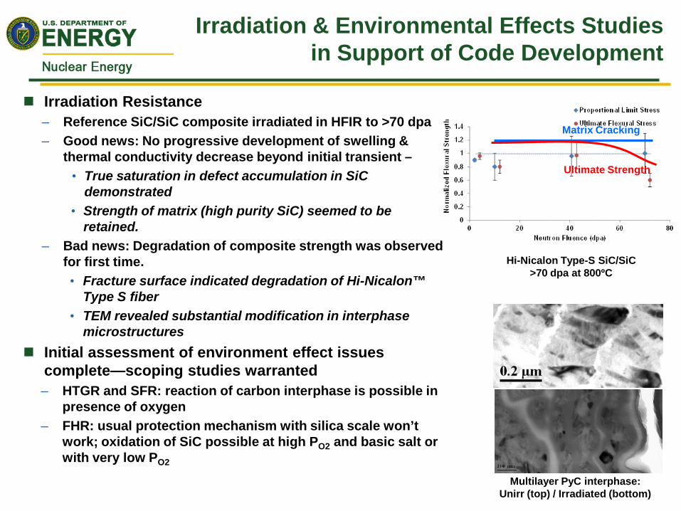
Irradiation & Environmental Effects Studies in Support of Code Development
Irradiation Resistance – Reference SiC/SiC composite irradiated in HFIR to >70 dpa – Good news: No progressive development of swelling &
thermal conductivity decrease beyond initial transient – • True saturation in defect accumulation in SiC
demonstrated • Strength of matrix (high purity SiC) seemed to be
retained. – Bad news: Degradation of composite strength was observed
for first time. • Fracture surface indicated degradation of Hi-Nicalon™
Type S fiber • TEM revealed substantial modification in interphase
microstructures Initial assessment of environment effect issues
complete—scoping studies warranted – HTGR and SFR: reaction of carbon interphase is possible in
presence of oxygen – FHR: usual protection mechanism with silica scale won’t
work; oxidation of SiC possible at high PO2 and basic salt or with very low PO2
Hi-Nicalon Type-S SiC/SiC >70 dpa at 800ºC
Matrix Cracking
Ultimate Strength
Multilayer PyC interphase: Unirr (top) / Irradiated (bottom)
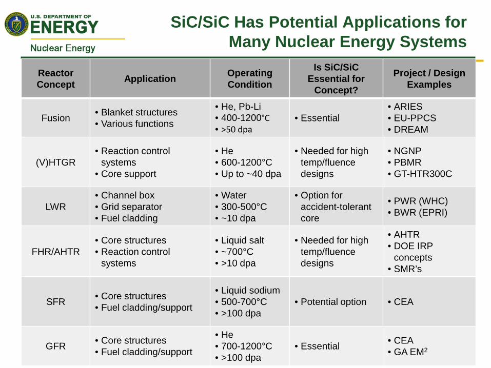
SiC/SiC Has Potential Applications for Many Nuclear Energy Systems
Reactor Concept Application Operating
Condition
Is SiC/SiC Essential for
Concept?
Project / Design Examples
Fusion • Blanket structures • Various functions
• He, Pb-Li • 400-1200°C • >50 dpa
• Essential • ARIES • EU-PPCS • DREAM
(V)HTGR • Reaction control
systems • Core support
• He • 600-1200°C • Up to ~40 dpa
• Needed for high temp/fluence designs
• NGNP • PBMR • GT-HTR300C
LWR • Channel box • Grid separator • Fuel cladding
• Water • 300-500°C • ~10 dpa
• Option for accident-tolerant core
• PWR (WHC) • BWR (EPRI)
FHR/AHTR • Core structures • Reaction control
systems
• Liquid salt • ~700°C • >10 dpa
• Needed for high temp/fluence designs
• AHTR • DOE IRP
concepts • SMR’s
SFR • Core structures • Fuel cladding/support
• Liquid sodium • 500-700°C • >100 dpa
• Potential option • CEA
GFR • Core structures • Fuel cladding/support
• He • 700-1200°C • >100 dpa
• Essential • CEA • GA EM2
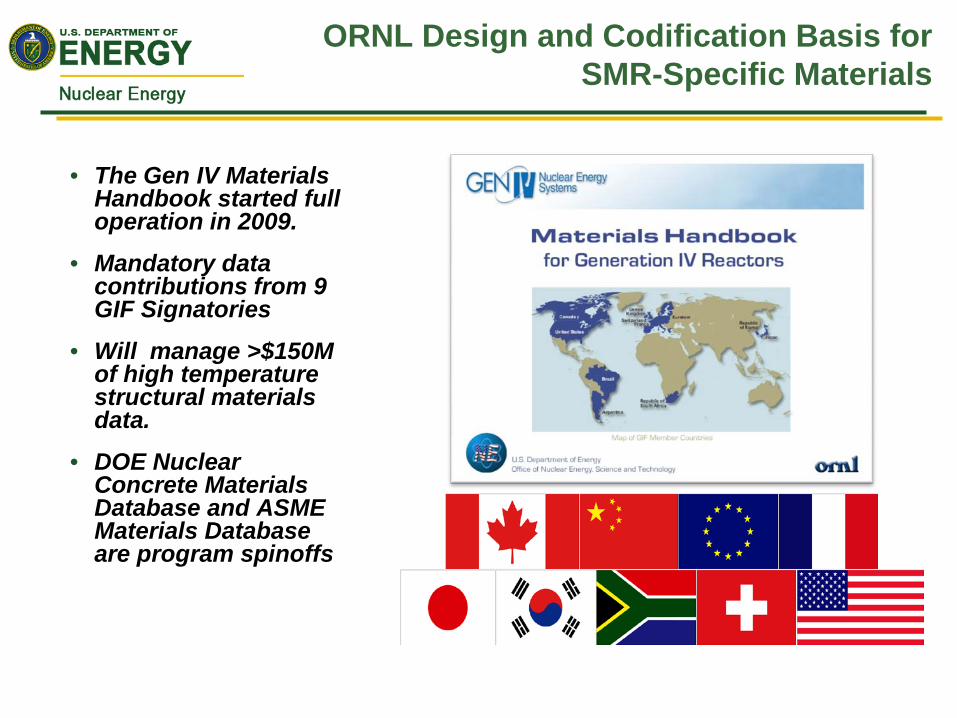
ORNL Design and Codification Basis for SMR-Specific Materials
• The Gen IV Materials Handbook started full operation in 2009.
• Mandatory data contributions from 9 GIF Signatories
• Will manage >$150M of high temperature structural materials data.
• DOE Nuclear Concrete Materials Database and ASME Materials Database are program spinoffs
21
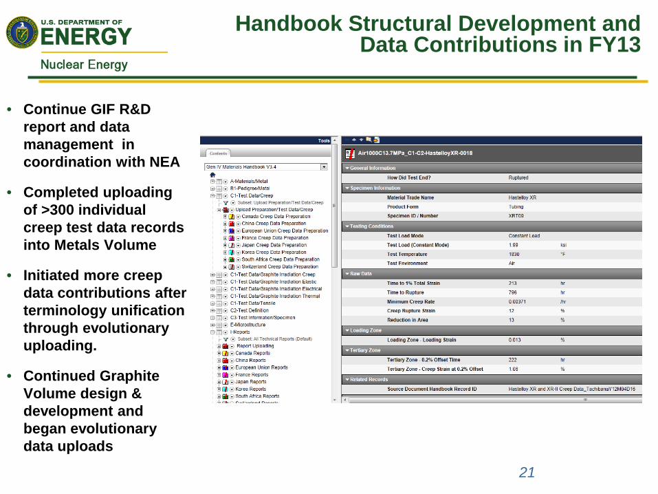
• Continue GIF R&D report and data management in coordination with NEA
• Completed uploading of >300 individual creep test data records into Metals Volume
• Initiated more creep data contributions after terminology unification through evolutionary uploading.
• Continued Graphite Volume design & development and began evolutionary data uploads
Handbook Structural Development and Data Contributions in FY13
Design and Codification Basis for aSMR/ARC Specific Materials – Gen IV
Materials Handbook Project
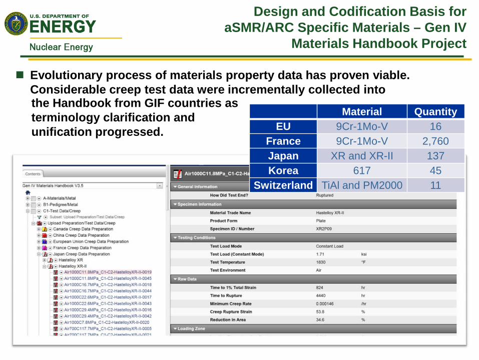
Evolutionary process of materials property data has proven viable. Considerable creep test data were incrementally collected into
Material Quantity EU 9Cr-1Mo-V 16
France 9Cr-1Mo-V 2,760 Japan XR and XR-II 137 Korea 617 45
Switzerland TiAl and PM2000 11
the Handbook from GIF countries as terminology clarification and unification progressed.
Design and Codification Basis for aSMR/ARC Specific Materials – Gen IV
Materials Handbook Project
Agreement was reached with Handbook base software vendor and Japan National Institute for Materials Science (NIMS) to add to Handbook a NIMS Database Module with considerable data applicable to aSMR/ARC specific materials including 304SS, 316SS, 800H, T91, T92 etc.
Database interoperability project for development of massive data exchange techniques under the US-EURATOM I-NERI has successfully achieved its goals.
– Project review concluded as a successful development.
– Review board requested an extension for actual data exchange between EU and DOE using the developed techniques and mechanisms.
Once Metals and Graphite Volumes are fully functional, the final volume on Ceramics and Composites will be initiated
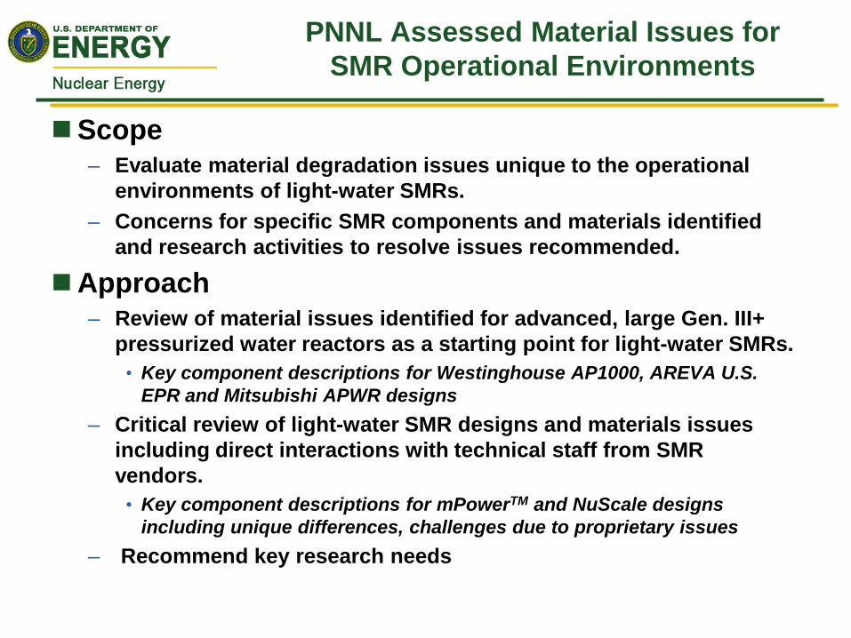
PNNL Assessed Material Issues for SMR Operational Environments
Scope – Evaluate material degradation issues unique to the operational
environments of light-water SMRs. – Concerns for specific SMR components and materials identified
and research activities to resolve issues recommended.
Approach – Review of material issues identified for advanced, large Gen. III+
pressurized water reactors as a starting point for light-water SMRs. • Key component descriptions for Westinghouse AP1000, AREVA U.S.
EPR and Mitsubishi APWR designs – Critical review of light-water SMR designs and materials issues
including direct interactions with technical staff from SMR vendors.
• Key component descriptions for mPowerTM and NuScale designs including unique differences, challenges due to proprietary issues
– Recommend key research needs

Material Issues Assessed for Gen III+ Large LWRs
Key Components are Described and Issues Evaluated
Source: U.S. EPR DCD
Material Selection Low-alloy Steel : SA-508 Gr. 3 – Cl. 1
Stainless Steel Cladding: 308/308L/309/309L/316/316L
Environment Tcold ~ 537ºF - 563ºF; Thot ~ 537ºF - 563ºF “Tcold heads” used in most designs
Neutron fluence: Φ ~ 9x10¹⁹ n/cm2 (welded core former) Φ ~ 1x10¹⁹ n/cm2 (heavy reflector core former)
Well controlled material chemistry, Low Initial RTNDT ~ 0 ˚F
Fabrication All forged ring segments – no vertical welds
Typically only one circumferential weld in or adjacent to active core height
RPV Beltline Example
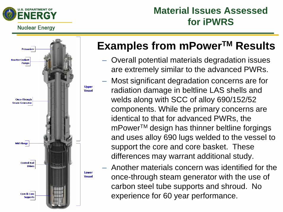
Material Issues Assessed for iPWRS
Examples from mPowerTM Results – Overall potential materials degradation issues
are extremely similar to the advanced PWRs. – Most significant degradation concerns are for
radiation damage in beltline LAS shells and welds along with SCC of alloy 690/152/52 components. While the primary concerns are identical to that for advanced PWRs, the mPowerTM design has thinner beltline forgings and uses alloy 690 lugs welded to the vessel to support the core and core basket. These differences may warrant additional study.
– Another materials concern was identified for the once-through steam generator with the use of carbon steel tube supports and shroud. No experience for 60 year performance.
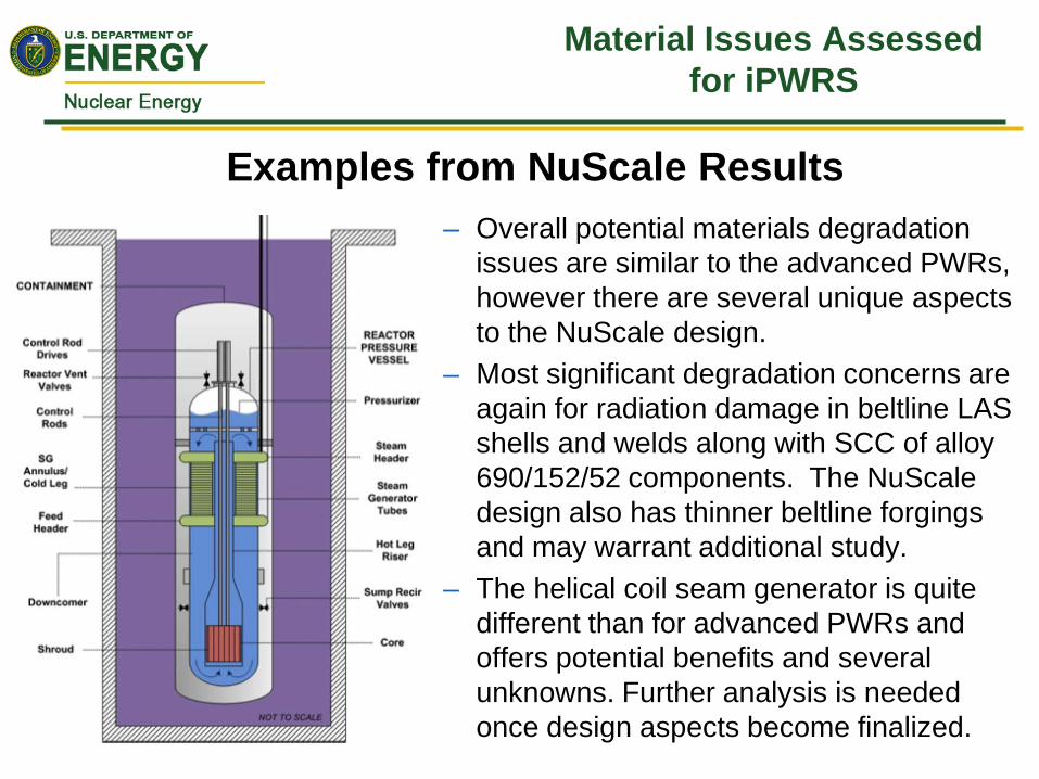
Examples from NuScale Results – Overall potential materials degradation
issues are similar to the advanced PWRs, however there are several unique aspects to the NuScale design.
– Most significant degradation concerns are again for radiation damage in beltline LAS shells and welds along with SCC of alloy 690/152/52 components. The NuScale design also has thinner beltline forgings and may warrant additional study.
– The helical coil seam generator is quite different than for advanced PWRs and offers potential benefits and several unknowns. Further analysis is needed once design aspects become finalized.
Material Issues Assessed for iPWRS

Assessment of Material Issues for SMR Completed
Project Summary – May 2012: Work started at PNNL; contact letters sent to mPowerTM,
NuScale, Westinghouse and Holtec; and subcontracts with LWR, expert consultants (Wayne Lunceford and Dave Sandusky) established.
– August-September 2012: Non-disclosure agreements setup and initial meetings held with mPowerTM and NuScale technical staff; review completed on advanced large PWRs by consultants.
– October-November 2012: Completed technical information exchange with vendors; first draft of review completed on materials issues and individual sections sent to vendors for final review.
– January 2013: Vendor reviews of individual sections completed and returned to PNNL, final draft of critical review in preparation.
– Milestone report completed/submitted February 2013. • Assessment of Materials Issues for Light-Water Small Modular
Reactors, D. Sandusky, W. Lunceford, S. M. Bruemmer, and M. A. Catalan, PNNL-22290
Top Related