


Languages
Pages
Legal

SV9000 AF DRIVES
Fieldbus Control Application
• User Manual
AD
JUSTA
BLE
FREQ
UEN
CY
DRIV
ES

SV9000 Fieldbus Control Application Page 1
Fieldbus ControlApplication(par. 0.1 = 0)
CONTENTS
1 General ............................................ 22 Control I/O ........................................ 23 Control signal logic .......................... 34 Parameter Group 0 .......................... 45 Parameters Group 1 ........................ 5
5.1 Parameter table ........................ 55.2 Description of Group1 par. ....... 6
6 Special parameters, Groups 2-11 .. 106.1 Parameter tables .................... 106.2 Description of Group 2 par. .... 19
7 Fault code ...................................... 468 Monitoring data............................... 46
TR
D.08H.23.T.Eev. 01
Page 2 Fieldbus Control Application SV9000
Referencepotentiometer 1- 10 kΩ
2 Control I/O
READY
RUN
220VAC
FAULT
outputs have extra alternatives in their controlparameters. The source of the free analog inputcan now be selected from the I/O Expander.These inputs also have parameters for signalarea etc. programming.
1 GeneralThe Fieldbus Application is an extendedversion of the normal Multipurpose application. Ithas parameters for torque control and for fieldbuscommunication. The following fieldbuses aresupported: Interbus, Modbus, Profibus, LonWorks,DeviceNet, and N2.The frequency reference, the analog and digital
Terminal Signal Description
1 +10Vref Reference output Voltage for a potentiometer, etc.
2 Vin+ Analog input, Frequency referencevoltage (programmable) range 0—10 V DC
3 GND I/O ground Ground for reference and controls
4 Iin+ Analog input, Default setting: not used
5 Iin- current (programmable) range 0—20 mA
6 +24V Control voltage output Voltage for switches, etc. max.. 0.1 A
7 GND I/O ground Ground for reference and controls
8 DIA1 Start forward Contact closed = start forward(programmable)
9 DIA2 Start reverse Contact closed = start reverse(Programmable)
10 DIA3 Fault reset Contact open = no action(programmable) Contact closed = fault reset
11 CMA Common for DIA1—DIA3 Connect to GND or +24V
12 +24V Control voltage output Voltage for switches, (same as #6)
13 GND I/O ground Ground for reference and controls
14 DIB4 Jog speed select Contact open = no action(programmable) Contact closed = jogging speed
15 DIB5 External fault Contact open = no fault(programmable) Contact closed = fault
16 DIB6 Accel./deceler. time select Contact open = par. 1.3, 1.4 in use(programmable) Contact closed = par. 4.3, 4.4 in use
17 CMB Common for DIB4—DIB6 Connect to GND or +24V
18 Iout+ Output frequency Programmable (par. 3. 1)
19 Iout- Analog output Range 0—20 mA/RL max. 500 Ω20 DO1 Digital output Programmable (par. 3. 6)
READY Open collector, I<50 mA, V<48 VDC
21 RO1 Relay output 1 Programmable (par. 3. 7)
22 RO1 RUN
23 RO1
24 RO2 Relay output 2 Programmable (par. 3. 8)
25 RO2 FAULT
26 RO2
Figure 2-1 Default I/O configuration and connection example of theFieldbus Control Application.
NOTE! Remember to connect theCMA and CMB inputs!!
TD.08H.23.T.ERev. 01

SV9000 Fieldbus Control Application Page 3
3 Control signal logic
In figure 3-1 the logic of I/O-control signals and push button signals from the panel are shown.
Figure 3-1 Control signal logic of the Fieldbus Application.Switch positions correspond to factory settings.
DIB4
DIB5
DIA1
DIB6
DIA2
P
P
P
DIA3
MP2BLOCK
>1
DIB5
DIB6
Internalfrequencyreference
InternalStart/Stop
Internalfault reset
Internalreverse
= control line= signal line
Programm.Start/Stopand Reversesignal logic
PROGRAMMABLEPUSH-BUTTON 2
Multi-stepspeeds(If any of DI_ inputs are pro-grammedfor thisfunction)
Joystickcontrol
Joystickcontrol
Motorisedpotentio-meterreference
Jog speedselection(programmable)
PARAMETERS1. 5 Reference selection1. 6 Jog speed ref. 10.1 Fieldbus control
Up
Down
(programmable)Fault reset
External fault(programmable)
Accel./deceler. time select(programmable)
Start REV.
Start FWD
Vin+
Iin±
Vin + IinVin - Iin Iin - VinVin x Iinmin(Vin,Iin)max(Vin,Iin)
Par. 9.1Torque reference
selection
Par. 6.1Motor control mode
Torque reference
scaling
Torque reference
Motor control modeTorquecontrol
DIA3 (par. 2.2=10)
Fieldbus
Fieldbus
Fie
ldbu
s
TD.08H.23.T.ERev. 01
Page 4 Fieldbus Control Application SV9000
4 Parameter group 0
rebmuN retemaraP egnaR petS tluafeD remotsuC noitpircseD
1.0noitacilppA
noitceles7-0 1 0
laicepsdedaol(Fieldbus Ctr=0)noitacilppa
noitacilppAcisaB=1noitacilppAdradnatS=2
lortnoCetomeR/lacoL=3noitacilppA
noitacilppAdeepSpets-itluM=4noitacilppAlortnoc-IP=5lortnoCesoprup-itluM=6
noitacilppAlortnoCnaFdnapmuP=7
noitacilppA
2.0 gnidaolretemaraP 5-0 1 0
gnidaoltceleS/ydaergnidaoL=0gnittestluafeddaoL=1
s'resusasretemaraperotS=2tes
sretemaraptess'resudaoleR=3lenapehtnisretemaraperotS=4
ehthtiwylnoelbissop()lenaplacihparg
ehtmorfsretemarapdaoL=5ehthtiwylnoelbissop(lenap
)lenaplacihparg
3.0 noitcelesegaugnaL 0 hsilgnE=0
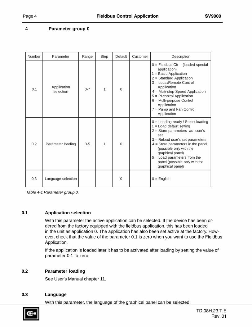
Table 4-1 Parameter group 0.
0.1 Application selection
With this parameter the active application can be selected. If the device has been or-dered from the factory equipped with the fieldbus application, this has been loadedin the unit as application 0. The application has also been set active at the factory. How-ever, check that the value of the parameter 0.1 is zero when you want to use the FieldbusApplication.
If the application is loaded later it has to be activated after loading by setting the value ofparameter 0.1 to zero.
0.2 Parameter loading
See User's Manual chapter 11.
0.3 Language
With this parameter, the language of the graphical panel can be selected.
TD.08H.23.T.ERev. 01

SV9000 Fieldbus Control Application Page 5
5 Basic parameters, Group 1
5.1 Parameter table
Code Parameter Range Step Default Custom Description Page
1. 1 Minimum frequency 0—120/500 Hz 1 Hz 0 Hz 6
1. 2 Maximum frequency 0—120/500 Hz 1 Hz 50 Hz * 6
1. 3 Acceleration time 1 0.1—3000 s 0.1 s 3 s Time from fmin (1. 1) to fmax (1. 2) 6
1. 4 Deceleration time 1 0.1—3000 s 0.1 s 3 s Time from fmax (1. 2) to fmin (1. 1) 6
1. 5 Reference selection 0—13 1 0 0 = Vin 3 = Vin - Iin 61 = Iin 4 = Iin - Vin2 = Vin + Iin 5 = Vin * Iin6 = Vin joystick control7 = Iin joystick control8 = Signal from internal motor pot.9 = Signal from internal motor pot. reset if SV9000 unit is stopped10 = Signal from internal motor pot.(stored in memory over utility break)11 = Min (Vin, Iin)12 = Max (Vin, Iin)13 = Panel reference r1
1. 6 Jog speed fmin —fmax 0.1 Hz 5 Hz 7reference (1. 1) (1. 2)
1. 7 Current limit 0.1—2.5 x InSV9 0.1 A 1.5 x InSV9 Output current limit [A] of the unit 7
1. 8 V/Hz ratio selection 0—2 1 0 0 = Linear 71 = Squared2 = Programmable V/Hz ratio
1. 9 V/Hz optimisation 0—1 1 0 0 = None 91 = Automatic torque boost
1. 10 Nominal voltage 180—690 1 V 230 V Voltage code 2 9of the motor 380 V Voltage code 4
480 V Voltage code 5575 V Voltage code 6
1. 11 Nominal frequency 30—500 Hz 1 Hz 60 Hz fn on the rating plate of 9of the motor the motor
1. 12 Nominal speed 1—20000 rpm 1 rpm 1710 rpm nn on the rating plate of 9of the motor the motor
1. 13 Nominal current 2.5 x InSV9 0.1 A InSV9 In on the rating plate of 9of the motor the motor
1. 14 Supply voltage 180—250 230 V Voltage code 2 9380—440 380 V Voltage code 4380—500 480 V Voltage code 5525—690 575 V Voltage code 6
1. 15 Parameter conceal 0—1 1 0 Visibility of the parameters: 90 = All parametergroups visible1 = Only group 1 is visible
1. 16 Parameter value lock 0—1 1 0 Disables parameter changes: 90 = Changes enabled1 = Changes disabled
Note! STOPO = Parameter value can be changed only when the drive is stopped.
Table 5-1 Group 1 basic parameters. * If 1. 2 >motor synchr. speed, check suitability for motor and drive system.
S T O PO
STOPO
STOPO
STOPO
STOPO
STOPO
STOPO
S T O PO
TD.08H.23.T.ERev. 01
Page 6 Fieldbus Control Application SV9000
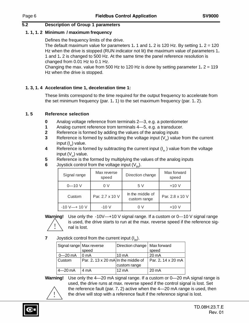
Warning! Use only the -10V—+10 V signal range. If a custom or 0—10 V signal rangeis used, the drive starts to run at the max. reverse speed if the reference sig-nal is lost.
7 Joystick control from the current input (Iin).
Signal range Max reverse Direction change Max forwardspeed speed
0—20 mA 0 mA 10 mA 20 mACustom Par. 2. 13 x 20 mA In the middle of Par. 2. 14 x 20 mA
custom range4—20 mA 4 mA 12 mA 20 mA
Warning! Use only the 4—20 mA signal range. If a custom or 0—20 mA signal range isused, the drive runs at max. reverse speed if the control signal is lost. Setthe reference fault (par. 7. 2) active when the 4—20 mA range is used, thenthe drive will stop with a reference fault if the reference signal is lost.
5.2 Description of Group 1 parameters
1. 1, 1. 2 Minimum / maximum frequency
Defines the frequency limits of the drive.The default maximum value for parameters 1. 1 and 1. 2 is 120 Hz. By setting 1. 2 = 120Hz when the drive is stopped (RUN indicator not lit) the maximum value of parameters 1.1 and 1. 2 is changed to 500 Hz. At the same time the panel reference resolution ischanged from 0.01 Hz to 0.1 Hz.Changing the max. value from 500 Hz to 120 Hz is done by setting parameter 1. 2 = 119Hz when the drive is stopped.
1. 3, 1. 4 Acceleration time 1, deceleration time 1:
These limits correspond to the time required for the output frequency to accelerate fromthe set minimum frequency (par. 1. 1) to the set maximum frequency (par. 1. 2).
1. 5 Reference selection
0 Analog voltage reference from terminals 2—3, e.g. a potentiometer1 Analog current reference trom terminals 4—5, e.g. a transducer.2 Reference is formed by adding the values of the analog inputs3 Reference is formed by subtracting the voltage input (Vin) value from the current
input (Iin) value.4 Reference is formed by subtracting the current input (Iin ) value from the voltage
input (Vin) value.5 Reference is the formed by multiplying the values of the analog inputs6 Joystick control from the voltage input (Vin).
!
!
egnarlangiSesreverxaM
deepsegnahcnoitceriD
drawrofxaMdeeps
V01—0 V0 V5 V01+
motsuC V01x7.2.raPfoelddimehtnI
egnarmotsucV01x8.2.raP
V01+—V01- V01- V0 V01+
TD.08H.23.T.ERev. 01

SV9000 Fieldbus Control Application Page 7
Note! When joystick control is used, the direction control is generated from thejoystick reference signal. See figure 5.4-1.Analog input scaling, parameters 2. 16—2. 19, is not used when joystickcontrol is used.
Fout
Uin
hystereesi +/-2% (+/-0,2 V)
+10V
-10V
Fmax(par 1.2)
Fmin.(par 1.1)
Fmin.(par 1.1)
Fmax(par 1.2)
Fout
UinUin
+10V
-10V
Fmax(par 1.2)
Fmax(par 1.2)
If minimum frequency (par 1. 1) >0, If minimum frequency (par 1. 1) = 0,
hysteresis is ± 2% at reversing point. there is no hysteresis at reversing point.
8 Reference value is changed with digital input signals DIA4 and DIA5.- switch in DIA3 closed = frequency reference increases- switch in DIA4 closed = frequency reference decreasesSpeed of reference change can be set with parameter 2. 20.
9 Same as setting 8 but the reference value is set to the minimum frequency(par. 1. 1) each time the drive is stopped.
10 Same as setting 8 but the reference is stored in memory over a utility break.When the value of parameter 1. 5 is set to 8, 9 or 10, the value of the param-eters 2. 4 and 2. 5 is automatically set to 11.
11 The smaller of signals Vin and Iin is the frequency reference12 The greater of signals Vin and Iin is the frequency reference13 Panel reference r1 is the frequency reference
1. 6 Jog speed reference
Parameter value defines the jog speed selected with a digital input.
1. 7 Current limit
This parameter determines the maximum motor current from the drive. To avoidmotor overload, set this parameter according to the rated current of the motor.
1. 8 V/Hz ratio selection
Linear: The voltage of the motor changes linearly with the frequency in the0 constant flux area from 0 Hz to the field weakening point (par. 6. 3)
where the nominal voltage is also supplied to the motor. See figure5-2. Linear V/Hz ratio should be used in constant torque applications.
This default setting should be used if there is no special need for anothersetting.
Fig. 5-1 Joystick control Vin signal -10 V—+10 V.
TD.08H.23.T.ERev. 01

Page 8 Fieldbus Control Application SV9000
Squared: The voltage of the motor changes following a squared curve form1 with the frequency in the area from 0 Hz to the field weakening
point (par. 6. 3) where the nominal voltage is also supplied tothe motor. See figure 5-2.The motor runs undermagnetised below the field weakening point and pro-duces less torque and electromechanical noise. Squared V/Hz ratio can beused in applications where torque demand of the load is proportional to thesquare of the speed, e.g. in centrifugal fans and pumps.
V[V]
f[Hz]
UD012K07
Default: Nominalvoltage of the motor
Linear
Squared
Field weakeningpoint
Default: Nominalfrequency of themotor
VnPar 6. 4
Par. 6. 3
V[V]
f[Hz]
UD012K08Par. 6. 5(Default. 5 Hz)
Par. 6. 6(Default 10%)
Par. 6. 7(Default 1.3%)
Default: Nominalvoltage of the motor
Field weakeningpoint
Default: Nominalfrequency of themotor
Programm.The V/Hz curve can be programmed with three different points.V/Hz curve The parameters for programming are explained in the chapter 5.5.2.2 Programmable V/Hz curve can be used if the other settings do not
satisfy the needs of the application. See figure 5 -3.
Figure 5-2 Linear and squared V/Hz curves.
Figure 5-3 Programmable V/Hz curve.
TD.08H.23.T.ERev. 01

SV9000 Fieldbus Control Application Page 9
1.9 V/Hz optimisation
Automatic The voltage to the motor changes automatically which makes thetorque motor produce sufficient torque to start and run at low frequencies. The
boost voltage increase depends on the motor type and power.
Automatic torque boost can be used in applications where starting torque due to startingfriction is high, e.g. in conveyors.
NOTE! In high torque - low speed applications - it is likely the motor will overheat. Ifthe motor has to run a prolonged time under these conditions, special atten-tion must be paid to cooling the motor. Use external cooling for the motor ifthe temperature tends to rise too high.
1. 10 Nominal voltage of the motor
Find the value Vn on the rating plate of the motor.
This parameter sets the voltage at the field weakening point, parameter 6. 4, to 100% xV
nmotor.
Note! If the nominal motor voltage is lower than the supply voltage, check that theinsulation level of the motor is adequate.
1. 11 Nominal frequency of the motor
Find the value fn on the rating plate of the motor.This parameter sets the field weakening point, parameter 6. 3, to the same value.
1. 12 Nominal speed of the motor
Find the value nn on the rating plate of the motor.
1. 13 Nominal current of the motor
Find the value In on the rating plate of the motor.
1. 14 Supply voltage
Set the parameter value according to the nominal voltage of the supply.Values are predefined for voltage codes 2, 4, 5 and 6. See table 5-1.
1. 15 Parameter conceal
Defines which parameter groups are available:
0 = all parameter groups are visible1 = only group 1 is visible
1. 16 Parameter value lock
Allows parameter value changes:
0 = parameter value changes enabled1 = parameter value changes disabled
!
TD.08H.23.T.ERev. 01

Page 10 Fieldbus Control Application SV9000
6 Special parameters, Groups 2—106.1 Parameter tables
Group 2, Input signal parameters
Code Parameter Range Step Default Custom Description Page
DIA1 DIA2
2. 1 Start/Stop logic 0—3 1 0 0 = Start forward Start reverse 19selection 1= Start/Stop Reverse
2 = Start/Stop Run enable3 = Start pulse Stop pulse4 = Start/stop pulse Run enable
2. 2 DIA3 function 0—9 1 7 0 = Not used 20(terminal 10) 1 = Ext. fault, closing contact
2 = External fault, opening contact3 = Run enable4 = Acc./dec. time selection5 = Reverse6 = Jog speed7 = Fault reset8 = Acc./dec. operation prohibit9 = DC-braking command10 = Torque control
2. 3 DIB4 function 0—10 1 6 0 = Not used 22(terminal 14) 1 = Ext. fault, closing contact
2 = External fault, opening contact3 = Run enable4 = Acc./dec. time selection5 = Reverse6 = Jog speed7 = Fault reset8 = Acc./dec. operation prohibit9 = DC-braking command10 = Multi-Step speed select 1
2. 4 DIB5 function 0—11 1 1 0 = Not used 22(terminal 15) 1 = Ext. fault, closing contact
2 = External fault, opening contact3 = Run enable4 = Acc./dec. time selection5 = Reverse6 = Jog speed7 = Fault reset8 = Acc./dec. operation prohibit9 = DC-braking command10 = Multi-Step speed select 211 = Motorised pot. speed up
2. 5 DIB6 function 0—11 1 4 0 = Not used 22(terminal 16) 1 = Ext. fault, closing contact
2 = External fault, opening contact3 = Run enable4 = Acc./dec. time selection5 = Reverse6 = Jog speed7 = Fault reset8 = Acc./dec. operation prohibit9 = DC-braking command10 = Multi-Step speed select 311 = Motorised pot. speed down
2. 6 Vin signal range 0—2 1 0 0 = 0—10 V 221 = Custom setting range2 = -10—+10 V (can be used only with Joystick control)
(Continues)
STOPO
STOPO
STOPO
STOPO
STOPO
12 = Auto
TD.08H.23.T.ERev. 01
SV9000 Fieldbus Control Application Page 11
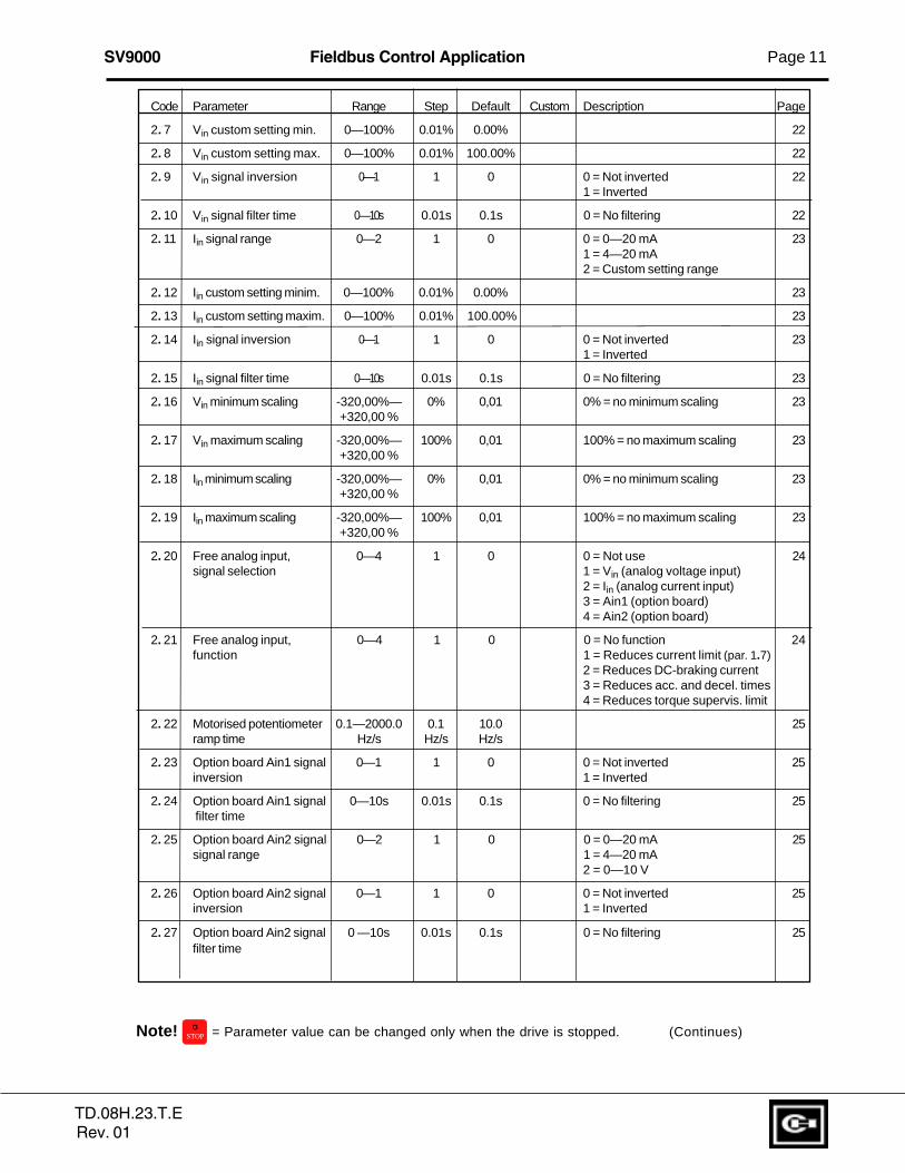
Code Parameter Range Step Default Custom Description Page
2. 7 Vin custom setting min. 0—100% 0.01% 0.00% 22
2. 8 Vin custom setting max. 0—100% 0.01% 100.00% 22
2. 9 Vin signal inversion 0—1 1 0 0 = Not inverted 221 = Inverted
2. 10 Vin signal filter time 0 —10s 0.01s 0.1s 0 = No filtering 22
2. 11 Iin signal range 0—2 1 0 0 = 0—20 mA 231 = 4—20 mA2 = Custom setting range
2. 12 Iin custom setting minim. 0—100% 0.01% 0.00% 23
2. 13 Iin custom setting maxim. 0—100% 0.01% 100.00% 23
2. 14 Iin signal inversion 0—1 1 0 0 = Not inverted 231 = Inverted
2. 15 Iin signal filter time 0 —10s 0.01s 0.1s 0 = No filtering 23
2. 16 Vin minimum scaling -320,00%— 0% 0,01 0% = no minimum scaling 23+320,00 %
2. 17 Vin maximum scaling -320,00%— 100% 0,01 100% = no maximum scaling 23+320,00 %
2. 18 Iin minimum scaling -320,00%— 0% 0,01 0% = no minimum scaling 23+320,00 %
2. 19 Iin maximum scaling -320,00%— 100% 0,01 100% = no maximum scaling 23+320,00 %
2. 20 Free analog input, 0—4 1 0 0 = Not use 24signal selection 1 = Vin (analog voltage input)
2 = Iin (analog current input)3 = Ain1 (option board)4 = Ain2 (option board)
2. 21 Free analog input, 0—4 1 0 0 = No function 24function 1 = Reduces current limit (par. 1.7)
2 = Reduces DC-braking current3 = Reduces acc. and decel. times4 = Reduces torque supervis. limit
2. 22 Motorised potentiometer 0.1—2000.0 0.1 10.0 25ramp time Hz/s Hz/s Hz/s
2. 23 Option board Ain1 signal 0—1 1 0 0 = Not inverted 25inversion 1 = Inverted
2. 24 Option board Ain1 signal 0—10s 0.01s 0.1s 0 = No filtering 25 filter time
2. 25 Option board Ain2 signal 0—2 1 0 0 = 0—20 mA 25signal range 1 = 4—20 mA
2 = 0—10 V
2. 26 Option board Ain2 signal 0—1 1 0 0 = Not inverted 25inversion 1 = Inverted
2. 27 Option board Ain2 signal 0 —10s 0.01s 0.1s 0 = No filtering 25filter time
Note! STOPO = Parameter value can be changed only when the drive is stopped. (Continues)
TD.08H.23.T.ERev. 01
Page 12 Fieldbus Control Application SV9000
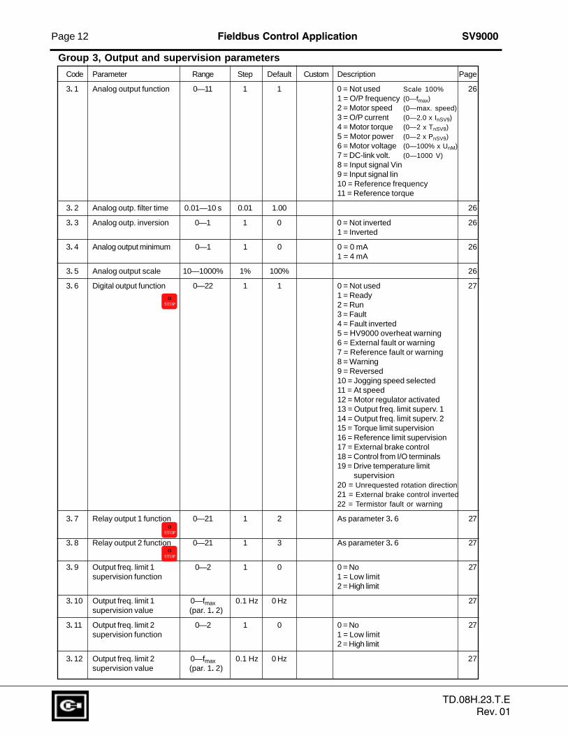
Group 3, Output and supervision parameters
Code Parameter Range Step Default Custom Description Page
3. 1 Analog output function 0—11 1 1 0 = Not used Scale 100% 261 = O/P frequency (0—fmax)2 = Motor speed (0—max. speed)3 = O/P current (0—2.0 x InSV9)4 = Motor torque (0—2 x TnSV9)5 = Motor power (0—2 x PnSV9)6 = Motor voltage (0—100% x UnM)7 = DC-link volt. (0—1000 V)8 = Input signal Vin9 = Input signal Iin10 = Reference frequency11 = Reference torque
3. 2 Analog outp. filter time 0.01—10 s 0.01 1.00 26
3. 3 Analog outp. inversion 0—1 1 0 0 = Not inverted 261 = Inverted
3. 4 Analog output minimum 0—1 1 0 0 = 0 mA 261 = 4 mA
3. 5 Analog output scale 10—1000% 1% 100% 26
3. 6 Digital output function 0—22 1 1 0 = Not used 271 = Ready2 = Run3 = Fault4 = Fault inverted5 = HV9000 overheat warning6 = External fault or warning7 = Reference fault or warning8 = Warning9 = Reversed10 = Jogging speed selected11 = At speed12 = Motor regulator activated13 = Output freq. limit superv. 114 = Output freq. limit superv. 215 = Torque limit supervision16 = Reference limit supervision17 = External brake control18 = Control from I/O terminals19 = Drive temperature limit supervision20 = Unrequested rotation direction21 = External brake control inverted22 = Termistor fault or warning
3. 7 Relay output 1 function 0—21 1 2 As parameter 3. 6 27
3. 8 Relay output 2 function 0—21 1 3 As parameter 3. 6 27
3. 9 Output freq. limit 1 0—2 1 0 0 = No 27supervision function 1 = Low limit
2 = High limit
3. 10 Output freq. limit 1 0—fmax 0.1 Hz 0 Hz 27supervision value (par. 1. 2)
3. 11 Output freq. limit 2 0—2 1 0 0 = No 27supervision function 1 = Low limit
2 = High limit
3. 12 Output freq. limit 2 0—fmax 0.1 Hz 0 Hz 27supervision value (par. 1. 2)
STOPO
STOPO
STOPO
TD.08H.23.T.ERev. 01

SV9000 Fieldbus Control Application Page 13
Code Parameter Range Step Default Custom Description Page
3. 13 Torque limit 0—2 1 0 0 = No 28supervision function 1 = Low limit
2 = High limit
3. 14 Torque limit 0—200% 1% 100% 28supervision value xTnSV9
3. 15 Reference limit 0—2 1 0 0 = No 28supervision function 1 = Low limit
2 = High limit
3. 16 Reference limit 0—fmax 0.1 Hz 0 Hz 28supervision value (par. 1. 2)
3. 17 Extern. brake Off-delay 0—100.0 s 0.1 s 0.5 s 28
3. 18 Extern. brake On-delay 0—100.0 s 0.1 s 1.5 s 28
3. 19 Drive 0—2 1 0 0 = No 28temperature limit 1 = Low limitsupervision function 2 = High limit
3. 20 Drive -10—+75°C 1°C +40°C 28temperature limit value
3. 21 I/O-expander board (opt.) 0—9 1 3 See parameter 3. 1 26analog output content
3. 22 I/O-expander board (opt.) 0.01—10 s 0.01 1.00 See parameter 3. 2 26analog output filter time
3. 23 I/O-expander board (opt.) 0—1 1 0 See parameter 3. 3 26analog output inversion
3. 24 I/O-expander board (opt.) 0—1 1 0 See parameter 3. 4 26analog output minimum
3. 25 I/O-expander board (opt.) 10—1000% 1 100% See parameter 3. 5 26analog output scale
3. 26 Analog output offset -100— 1 100% 29(basic control board) 100,0%
3. 27 I/O-expander board (opt.) -100— 1 100% 29analog output offset +100,0%
3. 28 Digital output DO1 0—320,00s 0,01 0,00 0,00 = delay not in use 29 on delay
3. 29 Digital output DO1 0—320,00s 0,01 0,00 0,00 = delay not in use 29off delay
3. 30 Relay output RO1 0—320,00s 0,01 0,00 0,00 = delay not in use 29 on delay
3. 31 Relay output RO1 0—320,00s 0,01 0,00 0,00 = delay not in use 29off delay
3. 32 Relay output RO1 0—320,00s 0,01 0,00 0,00 = delay not in use 29on delay
3.33 Relay output RO2 0—320,00s 0,01 0,00 0,00 = delay not in use 29
off delay
TD.08H.23.T.ERev. 01

Page 14 Fieldbus Control Application SV9000
Group 4, Drive control parameters
Code Parameter Range Step Default Custom Description Page
4. 1 Acc./Dec. ramp 1 shape 0—10 s 0.1 s 0 0 = Linear 30>0 = S-curve acc./dec. time
4. 2 Acc./Dec. ramp 2 shape 0—10 s 0.1 s 0 0 = Linear 30>0 = S-curve acc./dec. time
4. 3 Acceleration time 2 0.1—3000 s 0.1 s 10 s 31
4. 4 Deceleration time 2 0.1—3000 s 0.1 s 10 s 31
4. 5 Brake chopper 0—1 1 0 0 = Brake chopper not in use 311 = Brake chopper in use2 = External brake chopper
4. 6 Start function 0—1 1 0 0 = Ramp 311 = Flying start
4. 7 Stop function 0—1 1 0 0 = Coasting 311 = Ramp
4. 8 DC-braking current 0.15—1.5 0.1 A 0.5 x InSV9 31 x InSV9 (A)
4. 9 DC-braking time at Stop 0—250.0 s 0.1 s 0 s 0 = DC-brake is off at Stop 32
4. 10 Execute freq. of DC- 0.1—10 Hz 0.1 Hz 1.5 Hz 33brake during ramp Stop
4. 11 DC-brake time at Start 0.0—25.0 s 0.1 s 0 s 0 = DC-brake is off at Start 33
4. 12 Multi-step speed fmin —fmax 0.1 Hz 10 Hz 33reference 1 (1. 1) (1. 2)
4. 13 Multi-step speed fmin —fmax 0.1 Hz 15 Hz 33reference 2 (1. 1) (1. 2)
4. 14 Multi-step speed fmin —fmax 0.1 Hz 20 Hz 33reference 3 (1. 1) (1. 2)
4. 15 Multi-step speed fmin —fmax 0.1 Hz 25 Hz 33reference 4 (1. 1) (1. 2)
4. 16 Multi-step speed fmin —fmax 0.1 Hz 30 Hz 33reference 5 (1. 1) (1. 2)
4. 17 Multi-step speed fmin —fmax 0.1 Hz 40 Hz 33reference 6 (1. 1) (1. 2)
4. 18 Multi-step speed fmin —fmax 0.1 Hz 50 Hz 33reference 7 (1. 1) (1. 2)
Note! STOPO = Parameter value can be changed only when the drive is stopped.
STOPO
TD.08H.23.T.ERev. 01
SV9000 Fieldbus Control Application Page 15
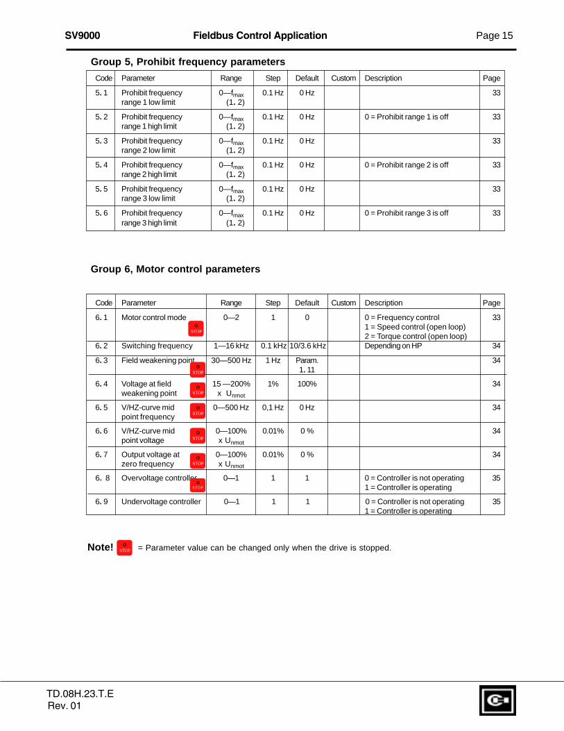
Group 5, Prohibit frequency parameters
Code Parameter Range Step Default Custom Description Page
5. 1 Prohibit frequency 0—fmax 0.1 Hz 0 Hz 33range 1 low limit (1. 2)
5. 2 Prohibit frequency 0—fmax 0.1 Hz 0 Hz 0 = Prohibit range 1 is off 33range 1 high limit (1. 2)
5. 3 Prohibit frequency 0—fmax 0.1 Hz 0 Hz 33range 2 low limit (1. 2)
5. 4 Prohibit frequency 0—fmax 0.1 Hz 0 Hz 0 = Prohibit range 2 is off 33range 2 high limit (1. 2)
5. 5 Prohibit frequency 0—fmax 0.1 Hz 0 Hz 33range 3 low limit (1. 2)
5. 6 Prohibit frequency 0—fmax 0.1 Hz 0 Hz 0 = Prohibit range 3 is off 33range 3 high limit (1. 2)
Group 6, Motor control parameters
Code Parameter Range Step Default Custom Description Page
6. 1 Motor control mode 0—2 1 0 0 = Frequency control 331 = Speed control (open loop)2 = Torque control (open loop)
6. 2 Switching frequency 1—16 kHz 0.1 kHz 10/3.6 kHz Depending on HP 34
6. 3 Field weakening point 30—500 Hz 1 Hz Param. 341. 11
6. 4 Voltage at field 15 —200% 1% 100% 34weakening point x Unmot
6. 5 V/HZ-curve mid 0—500 Hz 0,1 Hz 0 Hz 34point frequency
6. 6 V/HZ-curve mid 0—100% 0.01% 0 % 34point voltage x Unmot
6. 7 Output voltage at 0—100% 0.01% 0 % 34zero frequency x Unmot
6. 8 Overvoltage controller 0—1 1 1 0 = Controller is not operating 351 = Controller is operating
6. 9 Undervoltage controller 0—1 1 1 0 = Controller is not operating 351 = Controller is operating
Note! STOPO = Parameter value can be changed only when the drive is stopped.
STOPO
STOPO
STOPO
STOPO
STOPO
STOPO
S T O PO
TD.08H.23.T.ERev. 01

Page 16 Fieldbus Control Application SV9000
Group 7, Protections
Code Parameter Range Step Default Custom Description Page
7. 1 Response to 0—2 1 0 0 = No action 35reference fault 1 = Warning
2 = Fault, stop according to par 4.73 = Fault, stop always by coasting
7. 2 Response to 0—2 1 2 0 = No action 35external fault 1 = Warning
2 = Fault, stop according to par 4.73 = Fault, stop always by coasting
7. 3 Phase supervision of 0—2 2 2 0 = No action 35the motor 2 = Fault
7. 4 Earth fault protection 0—2 2 2 0 = No action 352 = Fault
7. 5 Motor thermal protection 0—2 1 2 0 = No action 361 = Warning2 = Fault
7. 6 Motor thermal protection 50.0—150 % 1.0 % 100.0% 36break point current x InMOTOR
7. 7 Motor thermal protection 10.0—150% 1.0 % 45.0% 37zero frequency current x InMOTOR
7. 8 Motor thermal protection 0.5—300.0 0,5 Default value is set according 37time constant minutes min. to motor nominal current
7. 9 Motor thermal protection 10—500 Hz 1 Hz 35 Hz 38break point frequency
7. 10 Stall protection 0—2 1 1 0 = No action 381 = Warning2 = Fault
7. 11 Stall current limit 10.0—200% 1.0% 130.0% 39x InMOTOR
7. 12 Stall time 2.0—120 s 1.0 s 15.0 s 39
7. 13 Maximum stall frequency 1—fmax 1 Hz 25 Hz 39
7. 14 Underload protection 0—2 1 0 0 = No action 401 = Warning2 = Fault
7. 15 Underload prot., field 20.0—150 % 1.0% 50.0% 40weakening area load x TnMOTOR
7. 16 Underload protection, 10.0—150.0% 1.0% 10.0% 40zero frequency load x TnMOTOR
7. 17 Underload time 2.0—600.0 s 1.0 s 20.0s 40
7. 18 Phase supervision of 0—2 2 2 0 = No action 41the supply voltage 2 = Fault
7. 19 Termistor input of 0—2 1 2 0 = No action 41I/O-Expander 1 = Warning
2 = Fault
7.20 Response to fieldbus 0 - 2 1 0 0 = Not used 41fault 1 = Warning
2 = Fault
TD.08H.23.T.ERev. 01

SV9000 Fieldbus Control Application Page 17
Group 8, Autorestart parameters
Code Parameter Range Step Default Custom Description Page
8. 1 Automatic restart: 0—10 1 0 0 = not in use 41number of tries
8. 2 Automatic restart: 1—6000 s 1 s 30 s 41trial time
8. 3 Automatic restart: 0—1 1 0 0 = Ramp 42start function 1 = Flying start
8. 4 Automatic restart of 0—1 1 0 0 = No 42undervoltage 1 = Yes
8. 5 Automatic restart of 0—1 1 0 0 = No 42overvoltage 1 = Yes
8. 6 Automatic restart of 0—1 1 0 0 = No 42overcurrent 1 = Yes
8. 7 Automatic restart of 0—1 1 0 0 = No 42reference fault 1 = Yes
8. 8 Automatic restart after 0—1 1 0 0 = No 42over/undertemperature 1 = Yesfault
Group 9, Torque Control
Code Parameter Range Step Default Custom Description Page
9. 1 Torque reference 0—2 1 0 0 = None 43selection 1 = Vin
2 = Iin
9. 2 Torque reference -100%— 1 0 0 = not in use 43scaling bias +100%
9. 3 Torque reference -320%— 1 100 100 = no scaling 43scaling gain +320%
9. 4 TC time constant 1—1000 ms 1 ms 128 ms 43
9. 5 TC min. control limit 0—10.00 Hz 0.01 Hz 3.00 Hz 43
TD.08H.23.T.ERev. 01
Page 18 Fieldbus Control Application SV9000
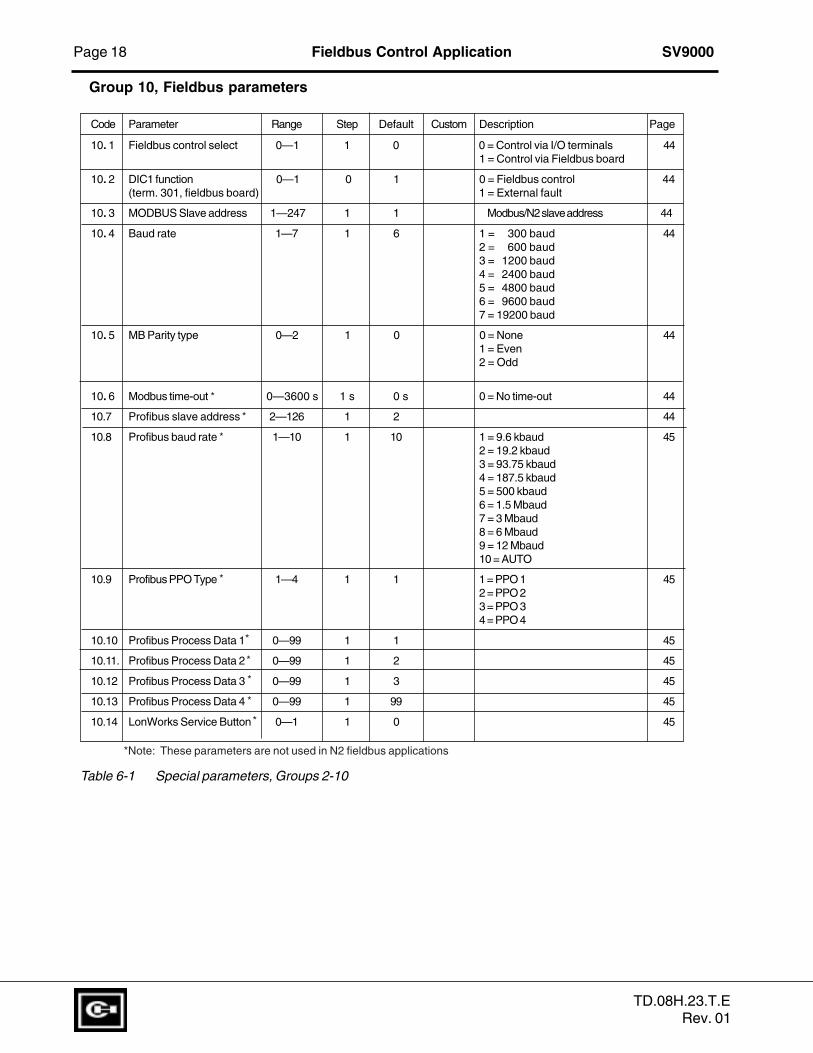
Group 10, Fieldbus parameters
Code Parameter Range Step Default Custom Description Page
10. 1 Fieldbus control select 0—1 1 0 0 = Control via I/O terminals 441 = Control via Fieldbus board
10. 2 DIC1 function 0—1 0 1 0 = Fieldbus control 44(term. 301, fieldbus board) 1 = External fault
10. 3 MODBUS Slave address 1—247 1 1 Modbus/N2 slave address 44
10. 4 Baud rate 1—7 1 6 1 = 300 baud 442 = 600 baud3 = 1200 baud4 = 2400 baud5 = 4800 baud6 = 9600 baud7 = 19200 baud
10. 5 MB Parity type 0—2 1 0 0 = None 441 = Even2 = Odd
10. 6 Modbus time-out 0—3600 s 1 s 0 s 0 = No time-out 44
10.7 Profibus slave address 2—126 1 2 44
10.8 Profibus baud rate 1—10 1 10 1 = 9.6 kbaud 452 = 19.2 kbaud3 = 93.75 kbaud4 = 187.5 kbaud5 = 500 kbaud6 = 1.5 Mbaud7 = 3 Mbaud8 = 6 Mbaud9 = 12 Mbaud10 = AUTO
10.9 Profibus PPO Type 1—4 1 1 1 = PPO 1 452 = PPO 23 = PPO 34 = PPO 4
10.10 Profibus Process Data 1 0—99 1 1 45
10.11. Profibus Process Data 2 0—99 1 2 45
10.12 Profibus Process Data 3 0—99 1 3 45
10.13 Profibus Process Data 4 0—99 1 99 45
10.14 LonWorks Service Button 0—1 1 0 45
Table 6-1 Special parameters, Groups 2-10
*
*
*
*
*
*
*
*
*
*Note: These parameters are not used in N2 fieldbus applications
TD.08H.23.T.ERev. 01

SV9000 Fieldbus Control Application Page 19
1 The first selected direction has the highest priority
2 When DIA1 opens, the direction of rotation starts to change
3 If Start forward (DIA1) and Start reverse (DIA2) signals are active simultaneously,the Start forward signal (DIA1) has priority.
1: DIA1: closed contact = start open contact = stopDIA2: closed contact = reverse open contact = forwardSee figure 6-2.
6.2 Description of Groups 2—10 parameters
2. 1 Start/Stop logic selection
0: DIA1: closed contact = start forwardDIA2: closed contact = start reverse,See figure 6-1.
DIA1
DIA2
1 2 3
t
UD009K09
Output frequency
Stop function(par 4. 7)= coasting
FWD
REV
DIA1
DIA2
t
UD012K10
Output frequency
Stop function(par 4. 7= coasting
FWD
REV
Figure 6-1 Start forward/Start reverse.
Figure 6-2 Start, Stop,reverse.
TD.08H.23.T.ERev. 01

Page 20 Fieldbus Control Application SV9000
t
min 50 ms
UD009K11
FWD
REV
Output frequency
Stop function(par 4. 7)= coasting
If Start and Stop pulses are simultaneous the Stop pulseoverrides the Start pulse
DIA1Start
DIA2Stop
t
min. 50 ms
UD009K12
FWD
REV
Outputfrequency
DIA1Start
DIA2Stop
2: DIA1: closed contact = start open contact = stopDIA2: closed contact = start enabled open contact = start disabled
3: 3-wire connection (pulse control):DIA1: closed contact = start pulseDIA2: closed contact = stop pulse(DIA3 can be programmed for reverse command)
See figure 6-3
4: DIA1: closed contact = start/stop pulseDIA2: closed contact = start enabled
Figure 6-4. Start / Stop pulse, Run enable.
2.2 DIA3 function
1: External fault, closing contact = Fault is shown and motor is stopped when theinput is active.
2: External fault, opening contact = Fault is shown and motor is stopped when theinput is not active.
3: Run enable contact open = Motor start disabledcontact closed = Motor start enabled
4: Acc./Dec contact open = Acceleration/deceleration time 1 selected time select. contact closed = Acceleration/deceleration time 2 selected
Figure 6.3 Start pulse / Stop pulse
Run Enable
TD.08H.23.T.ERev. 01

SV9000 Fieldbus Control Application Page 21
5: Reverse contact open = Forward Can be used for reversing ifcontact closed = Reverse parameter 2.1 has value 3
6: Jog. speed contact closed = Jogging speed selected for freq. reference7: Fault reset contact closed = Resets all faults8: Acc./Dec. operation prohibited
contact closed = Stops acceleration or deceleration until the contact isopened
9: DC-braking commandcontact closed = In Stop mode, the DC-braking operates until the con-
tact is opened, see figure 5.6-4. DC-brake current isset with parameter 4.8.
10: Torque controlcontact closed = Forces the motor control mode to torque control, see
par. 6.1
t
UD012K32
Param. 4. 10
DIA3
t
UD012K32
DIA3
RUNSTOP
Output frequency
a) DIA3 as DC-brake command input and stop-mode = Ramp
b) DIA3 as DC-brake command input and stop-mode = Coasting
RUNSTOP
Figure 6-5 DIA3 as DC-brake command input: a) Stop-mode = Ramp, b) Stop-mode = Coasting.
TD.08H.23.T.ERev. 01

Page 22 Fieldbus Control Application SV9000
2.3 DIB4 functionSelections are same as in 2. 2 except :10: Multi-Step contact closed = Selection 1 active speed select 1
2.4 DIB5 functionSelections are same as in 2. 2 except :10: Multi-Step contact closed = Selection 2 active speed select 211: Motor pot. contact closed = Reference decreases until the contact is UP opened
2.5 DIB6 functionSelections are same as in 2. 2 except :10: Multi-Step contact closed = Selection 3 active speed select 311: Motor pot. contact closed = Reference decreases until the contact is DOWN opened
2. 6 Vin signal range
0 = Signal range 0—+10 V1 = Custom setting range from custom minimum (par. 2. 4) to custom maximum (par. 2. 5)2 = Signal range -10—+10 V , can be used only with Joystick control
2. 7-2. 8 Vin custom setting minimum/maximum
With these parameters, Vin can be set for any input signal span within 0—10 V.
Minimum setting: Set the Vin signal to its minimum level, select parameter 2. 4, pressthe Enter button
Maximum setting: Set the Vin signal to its maximum level, select parameter 2. 5, pressthe Enter button
Note! These parameters can only be set with this procedure (not with the arrow up/arrow down buttons)
2. 9 Vin signal inversion
Parameter 2. 9 = 0, no inversion ofthe analog V
in signal.
Parameter 2. 9 = 1, inversion of theanalog V
in signal.
2. 10 Vin signal filter time
Filters out disturbances from theincoming analog Vin signal. Longfiltering time makes regulation re-sponse slower. See figure 6-6.
%
100%
63%
Par. 2. 10
t [s]
UD009K37
Filtered signal
Unfiltered signal
Figure 6-6 Vin signal filtering.
TD.08H.23.T.ERev. 01

SV9000 Fieldbus Control Application Page 23
2. 11 Analog input Iin signal range
0 = 0—20 mA1 = 4—20 mA2 = Custom signal span
2. 12 Analog input Iin custom2. 13 setting minimum/maximum
With these parameters, the scaling of the input current signal (Iin) range can be set be-
tween 0—20 mA.
Minimum setting:Set the Iin signal to its minimum level, select parameter 2. 12, press the Enter button.
Maximum setting:Set the Iin signal to its maximum level, select parameter 2. 13, press the Enter button.
Note! These parameters can only be set with this procedure (not with the arrow up/arrow down buttons)
2. 14 Analog input I in inversion
Parameter 2. 14 = 0, no inversion ofthe Iin inputParameter 2. 14 = 1, inversion of theIin
input.
2. 15 Analog input I in filter time
Filters out disturbances from theincoming analog Iin signal.Long filtering time makes controlresponse slower. See figure 6-7.
%
100%
63%
Par. 2. 15
t [s]
UD012K40
Filtered signal
Unfiltered signal
Figure 6-7 Analog input Iin filter time
2. 16 Vin signal minimum scaling
Sets the minimum scaling point for Vin
signal. See figure 6-8.
2. 17 Vin signal maximum scaling
Sets the maximum scaling point for Vin
signal. See figure 6-8.
2. 18 Iin signal minimum scaling
Sets the minimum scaling point for Iin signal. See figure 6-8.
2. 19 Iin signal maximum scaling
Sets the maximum scaling point for Iin signal. See figure 6-8.
TD.08H.23.T.ERev. 01

Page 24 Fieldbus Control Application SV9000
0
1 00 %P ar. 4. 8
0,1 5 x InFU
C h0 12 K58
D C -brak ingcu rre nt
F re e ana loginp ut
S ig na l ra ng e
2. 20 Free analog input signal
Selection of input signal of the free analog input (an input not used as a reference sig-nal):0 = Not in use1 = Voltage signal Vin
2 = Current signal Iin
3 = Voltage signal Ain1 from terminals 202-203 of I/O Expander4 = Analog signal Ain2 from terminals 204-205 of I/O Expander
- current signal SV9IOC100CN- voltage signal SV9IOC102CN
2. 21 Free analog input signal function
This parameter sets the function ofthe free analog input:
0 = Function is not used
1 = Reducing motor current limit(par. 1. 7). This signal will adjustthe maximum motor current be-tween 0 and parameter max. limitset with parameter 1.7. See fig-ure 6-9.
2 = Reducing DC brake current.
The DC braking current can bereduced with the free analoginput signal, between 0.15xInSV9and current set with parameter4. 8. See figure 6-10.
0
Par. 2. 19 = -30%Par. 2. 20 = 140%
100
Ch012K34
100 140-30
004
100
0
Par. 2. 19 = 30%Par. 2. 20 = 80%
1008030
10.0 V20.0 mA20.0 mA
76.5(15.3 mA)
17.7(3.5 mA)
Scaledinput signal [%]
Analoginput [%]
Scaledinput signal [%]
Analoginput [%]
004
10.0 V8.03.020.0 mA16.06.0
16.88.8 20.0 mA
100%Par. 1. 7
Ch012K61
Torque limit
Analoginput
Signal range0 V0 mA4 mACustom
10 V20 mA20 mACustom
Figure 6-9 Reducing max. motor current.
Figure 6-10 Reducing DC brake current.
Figure 6-8 Examples of the scaling of Vin and Iin inputs .
TD.08H.23.T.ERev. 01
SV9000 Fieldbus Control Application Page 25
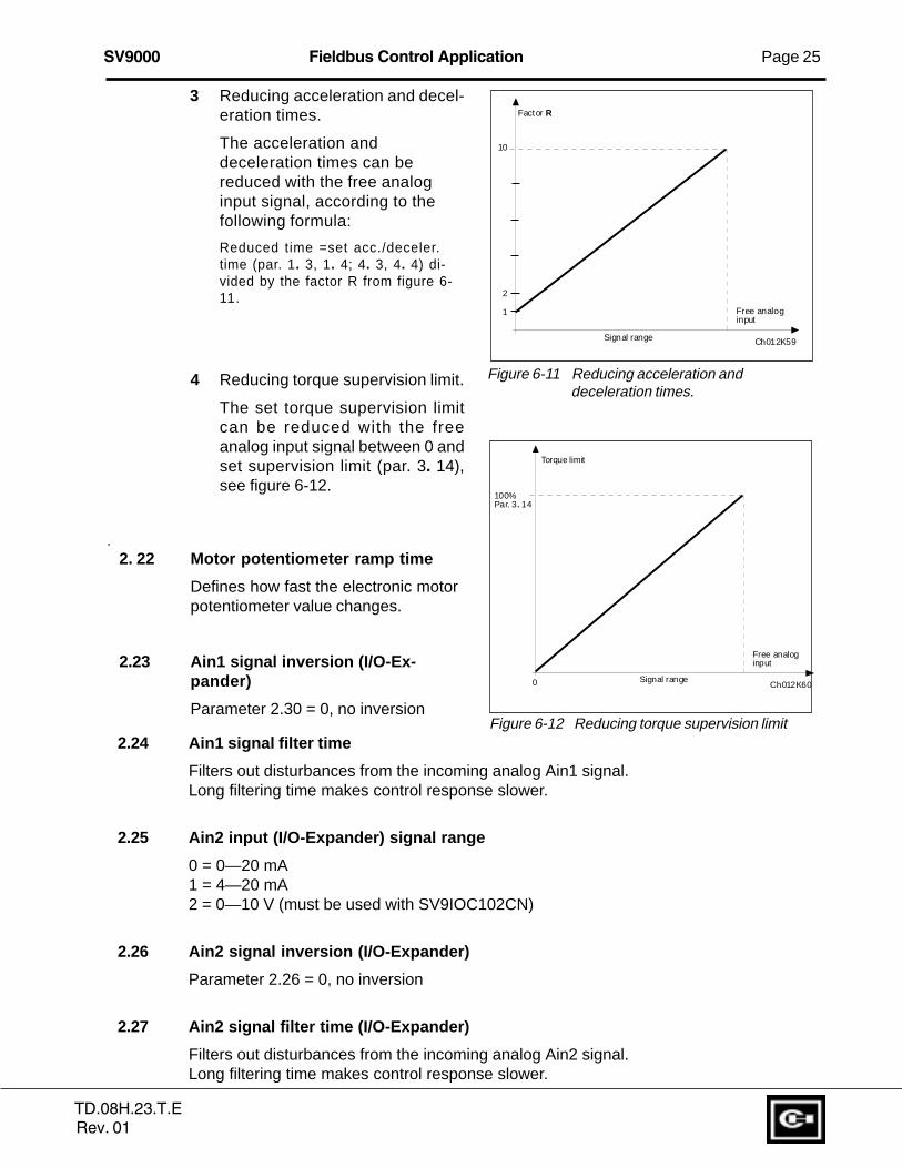
3 Reducing acceleration and decel-eration times.
The acceleration anddeceleration times can bereduced with the free analoginput signal, according to thefollowing formula:
Reduced time =set acc./deceler.time (par. 1. 3, 1. 4; 4. 3, 4. 4) di-vided by the factor R from figure 6-11.
4 Reducing torque supervision limit.
The set torque supervision limitcan be reduced with the freeanalog input signal between 0 andset supervision limit (par. 3. 14),see figure 6-12.
.2. 22 Motor potentiometer ramp time
Defines how fast the electronic motorpotentiometer value changes.
2.23 Ain1 signal inversion (I/O-Ex-pander)
Parameter 2.30 = 0, no inversion
10
1
Ch012K59
2
Factor R
Free analoginput
Signal range
0
100%Par. 3. 14
Ch012K60
Torque limit
Free analoginput
Signal range
2.24 Ain1 signal filter time
Filters out disturbances from the incoming analog Ain1 signal.Long filtering time makes control response slower.
2.25 Ain2 input (I/O-Expander) signal range
0 = 0—20 mA1 = 4—20 mA2 = 0—10 V (must be used with SV9IOC102CN)
2.26 Ain2 signal inversion (I/O-Expander)
Parameter 2.26 = 0, no inversion
2.27 Ain2 signal filter time (I/O-Expander)
Filters out disturbances from the incoming analog Ain2 signal.Long filtering time makes control response slower.
Figure 6-11 Reducing acceleration anddeceleration times.
Figure 6-12 Reducing torque supervision limit
TD.08H.23.T.ERev. 01

Page 26 Fieldbus Control Application SV9000
3. 1 Analog output function
See table on page 12.
3. 2 Analog output filter time
Filters the analog output signal.See figure 6-13.
3.3 Analog output invert
Inverts the analog output signal:max. output signal = minimum setvalue
min. output signal = maximum setvalue
3. 4 Analog output minimum
Defines the signal minimum tobe either 0 mA or 4 mA (livingzero). See figure 6-15.
%
100%
63%
Par. 3. 2
t [s]
UD009K16
Filtered signal
Unfiltered signal
1.00
20 mA
4 mA
10 mA
0.50 mA
Param. 3. 5= 200%
Param. 3. 5= 100%
Param. 3. 5= 50%
12 mA
Ch012K17
Analogoutputcurrent
Selected (para. 3. 1) signal max. value
1.00
20 mA
4 mA
10 mA
0.50 mA
Param. 3. 5= 200%
Param. 3. 5= 100%
Param. 3. 5= 50%
Par. 3. 4 = 1
Par. 3. 4 = 0
Ch012K18
12 mA
Analogoutputcurrent
Max. value of signalselected by param. 3. 1
Figure 6-13 Analog output filtering.
Figure 6-14 Analog output invert.
Figure 6-15 Analog output scale.
3. 5 Analog output scale
Scaling factor for the analogoutput. See figure 6-15.
Signal Max. value of the signal
Output fre- Max. frequency (p. 1. 2)quencyMotor speed Max. speed (nnxfmax/fn)Output 2 x InSV9
currentMotor torque 2 x TnSV9
Motor power 2 x PnSV9
Motor voltage 100% x Vnmotor
DC-link volt. 1000 V
Vin signal Max VinIin signal Max Iin
TD.08H.23.T.ERev. 01

SV9000 Fieldbus Control Application Page 27
3. 6 Digital output function3. 7 Relay output 1 function3. 8 Relay output 2 function
Setting value Signal content
0 = Not used Out of operationDigital output DO1 sinks the current and programmablerelay (RO1, RO2) is activated when:
1 = Ready The drive is ready to operate2 = Run The drive operates (motor is running)3 = Fault A fault trip has occurred4 = Fault inverted A fault trip has not occurred5 = SV9000 overheat warning The heat-sink temperature exceeds +70°C6 = External fault or warning Fault or warning depending on parameter 7. 27 = Reference fault or warning Fault or warning depending on parameter 7. 1 - if analog
reference is 4—20 mA and signal is < 4 mA8 = Warning Always if a warning exists9 = Reversed The reverse command has been selected10 = Jog speed Jog speed has been selected with digital input11 = At speed The output frequency has reached the set reference12 = Motor regulator activated Overvoltage or overcurrent regulator was activated13 = Output frequency supervision 1 The output frequency goes outside of the set supervision.
Low limit/ High limit (par. 3. 9 and 3. 10)14 = Output frequency supervision 2 The output frequency goes outside of the set supervision.
Low limit/ High limit (par. 3. 11 and 3. 12)15 = Torque limit supervision The motor torque goes outside of the set supervision.
Low limit/ High limit (par. 3. 13 and 3. 14)16 = Reference limit supervision Reference goes outside of the set supervision. Low limit/
High limit (par. 3. 15 and 3. 16)17 = External brake control External brake ON/OFF control with programmable delay
(par 3. 17 and 3. 18)18 = Control from I/O terminals External control mode selected with progr. push-button #219 = Drive Temperature on drive goes outside the temperature limit supervision set supervision limits (par. 3. 19 and 3. 20)20 = Unrequested rotation direction Rotation direction of the motor shaft is different from the
requested one21 = External brake control inverted External brake ON/OFF control (par. 3.17 and 3.18), output
active when brake control is OFF22 = Thermistor fault or warning The thermistor input of option board indicates overtem-
perature. Fault or warning depending on parameter 7.19
Table 6-2 Output signals via DO1 and output relays RO1 and RO2.
3. 9 Output frequency limit 1, supervision function3. 11 Output frequency limit 2, supervision function
0 = No supervision1 = Low limit supervision2 = High limit supervisionIf the output frequency goes under/over the set limit (3. 10, 3. 12) this function generatesa warning message via the digital output DO1 and via a relay output RO1 or RO2 de-pending on the settings of the parameters 3. 6—3. 8.
3. 10 Output frequency limit 1, supervision value3. 12 Output frequency limit 2, supervision value
The frequency value to be supervised by the parameter 3. 9 (3. 11).See figure 6-16.
TD.08H.23.T.ERev. 01

Page 28 Fieldbus Control Application SV9000
3. 13 Torque limit , supervision func-tion
0 = No supervision1 = Low limit supervision2 = High limit supervision
If the calculated torque value goesunder/over the set limit (3. 14) thisfunction generates a warning mes-sage via the digital output DO1, via arelay output RO1 or RO2 dependingon the settings of the parameters 3.6—3. 8.
3. 14 Torque limit , supervision value
The calculated torque value to be supervised by the parameter 3. 13.
3. 15 Reference limit , supervision function
0 = No supervision1 = Low limit supervision2 = High limit supervision
If the reference value goes under/over the set limit (3. 16) this function generates awarning message via the digital output DO1 or via a relay output RO1 or RO2 dependingon the settings of the parameters 3. 6—3. 8. The supervised reference is the currentlyactive reference. It can be source A or B reference, depending on the DIB6 input, or thepanel reference if the panel is the active control source.
3. 16 Reference limit , supervision value
The frequency value to be supervised by the parameter 3. 15.
3. 17 External brake-off delay3. 18 External brake-on delay
With these parameters the timing of external brake can be linked to the Start and Stopcontrol signals, see figure 6-17. The brake control signal can be programmed via thedigital output DO1 or via one of relay outputs RO1 and RO2, see parameters 3. 6—3. 8.
3. 19 Drive temperature limit supervision function
0 = No supervision1 = Low limit supervision2 = High limit supervision
If the temperature of the drive goes under/over the set limit (3. 20) this function gener-ates a warning message via the digital output DO1 or via the relay outputs RO1 or RO2depending on the settings of the parameters 3. 6—3. 8.
Par 3. 10
f[Hz]
t
21 RO122 RO1 23 RO1
21 RO122 RO1 23 RO1
21 RO122 RO1 23 RO1
UD009K19
Example:
Par. 3.9 = 2
Figure 6-16 Output frequency supervision.
TD.08H.23.T.ERev. 01

SV9000 Fieldbus Control Application Page 29
3. 20 Drive temperature limit value
The temperature value to be supervised by the parameter 3. 19.3.26 Analog outputoffset
3.27 I/O-Expander analog output offset
With these parameters the offsets of the basic control board and I/O-Expanderanalog outputs can be set. See figure 6-17.
3.28 Digital output DO1 on-delay3.29 Digital output DO1 off-delay3.30 Relay output RO1 on-delay3.31 Relay output RO1 off-delay3.32 Relay output RO2 on-delay3.33 Relay output RO2 off-delay
With these parameters it is possible to set on- and off-delays for the digital andrelay outputs. See figure 6-18.
ON-delay OFF-delay
Signal programmed todigital or relay output
DO, RO1 or RO2 output
ud182k_2
Figure 6-18. Digital and relay outputs. On- and off-delays
1.00
20 mA
0.50 mA
Param. 3. 26= 25% (+5 mA)
Param. 3. 5= 100%
Param. 3. 26= -30%(-6mA)
choffse.fh3
Analogoutputcurrent
Maximum value of selected signal
Figure 6-17. Analog output offset
TD.08H.23.T.ERev. 01

Page 30 Fieldbus Control Application SV9000
4. 1 Acc/Dec ramp 1 shape4. 2 Acc/Dec ramp 2 shape
The start and end of the acceleration and deceleration ramps can be smoothed withthese parameters. Setting the value = 0 gives you a linear ramp shape. The output fre-quency immediately follows the input with a ramp time set by parameters 1. 3 and 1. 4(4. 3 and 4. 4).
Setting 0.1—10 seconds for 4. 1 (4. 2) causes an S-shaped ramp. The speed changesare smooth. Parameters 1. 3 and 1. 4 (4. 3 and 4. 4) determines the ramp time of theacceleration/deceleration in the middle of the curve. See figure 6-20.
4. 3 Acceleration time 24. 4 Deceleration time 2
These values correspond to the timerequired for the output frequency toaccelerate from the set minimumfrequency (par. 1. 1) to the set maxi-mum frequency (par. 1. 2). Withthese parameters it is possible toset two different acceleration/decel-eration time sets for one application.The active set can be selected withthe programmable signal DIA3 ofthis application, see parameter 2. 2.Acceleration/deceleration times canbe reduced with an external freeanalog input signal, see parameters2. 18 and 2. 19.
[Hz]
[t]
4. 1 (4. 2)
4. 1 (4. 2)
UD009K20
1. 3, 1. 4(4. 3, 4. 4)
tOFF = Par. 3. 17 tON = Par. 3. 18
tOFF = Par. 3. 17 tON = Par. 3. 18
t
a)
t
b)
UD012K45
DIA1: RUN FWD
STOP
External
BRAKE: OFF
ONDigital orrelay output
DIA2: RUN REV
STOP
DIA1: START
PULSE
External
BRAKE: OFF
ONDigital orrelay output
DIA2: STOP
PULSE
Figure 6-20 S-shaped acceleration/deceleration.
Figure 6-19 External brake control: a) Start/Stop logic selection par. 2. 1 = 0, 1 or 2 ;b)Start/Stop logic selection par. 2. 1 = 3.
TD.08H.23.T.ERev. 01

SV9000 Fieldbus Control Application Page 31
4. 5 Brake chopper
0 = No brake chopper1 = Brake chopper and brake resistor installed2 = External brake chopper
When the drive is decelerating the motor, the energy stored in the inertia of the motorand the load are fed into the external brake resistor. If the brake resistor is selected cor-rectly the drive is able to brake the load with a torque equal to the e acceleration torque.See the separate Brake resistor installation manual.
4. 6 Start function
Ramp:
0 The drive starts from 0 Hz and accelerates to the set reference frequency with theset acceleration time. (Load inertia or starting friction may cause prolonged accel-eration times).
Flying start:
1 The drive is able to start into a running motor by first finding the speed the motor isrunning at. Searching starts from the maximum frequency down until the actualfrequency is reached. The output frequency then accelerates/decelerates to theset reference value at a rate set by the acceleration/deceleration ramp param-eters.
Use this mode if the motor is coasting when the start command is given. With theflying start it is possible to ride through short utility voltage interruptions.
4. 7 Stop function
Coasting:
0 The motor coasts to a halt without any control from the drive, after the Stop com-mand.
Ramp:
1 After the Stop command, the speed of the motor is decelerated according to theset deceleration parameters. If the regenerated energy is high it may be necessaryto use an external braking resistor for faster deceleration.
4. 8 DC braking current
Defines the current injected into the motor during DC braking.
The DC raking current can be reduced from the setpoint with an external free analogsignal, see parameters 2.20 and 2.21
4. 9 DC braking time at stop
Determines whether braking is ON or OFF. It also determines the braking duration time ofthe DC-brake when the motor is stopping. The function of the DC-brake depends on thestop function, parameter 4. 7. See figure 6-21.
0 DC-brake is not used
>0 DC-brake is in use and its function depends on the Stop function, (param. 4. 7), andthe time depends on the value of parameter 4. 9:
TD.08H.23.T.ERev. 01

Page 32 Fieldbus Control Application SV9000
t = param. 4. 9
t
Param. 4. 10
fout
UD009K23
Motor speed
Output frequency
DC-braking
RUNSTOP
0,1x fn
fout fout
fn fn
t t
t = 1 x par. 4. 9 t = 0.1 x par. 4. 9
UD009K21RUNSTOP
RUNSTOP
Output frequency
Motor speed
Output frequency
Motor speed
DC-braking ON
DC-braking ON
Figure 6-21 DC-braking time when stop = coasting.
Figure 6-22 DC-braking time when stop function= ramp.
Stop-function = 0 (coasting):
After the stop command, the motor will coast to a stop with the SV9000 off.
With DC-injection, the motor can be electrically stopped in the shortest possible timewithout using an optional external braking resistor.
The braking time is scaled according to the frequency when the DC-braking starts. Ifthe frequency is >nominal frequency of the motor (par. 1.11), the value of parameter4.9 determines the braking time. When the frequency is <10% of the nominal, thebraking time is 10% of the set value of parameter 4.9.
Stop-function = 1 (ramp):
After the Stop command, the speed of the motor is reduced based on decelerationparameters. If no regeneration occurs due to load inertia DC-braking starts at a speeddefine the parameter 4. 10.
The braking time is defined with parameter 4. 9.
If a high inertia exists, it is recommended to use an external braking resistor for fasterdeceleration. See figure 6-22.
4. 10 Execute frequency of DC-brakeduring ramp Stop
See figure 6-22.
TD.08H.23.T.ERev. 01

SV9000 Fieldbus Control Application Page 33
t
UD009K22
Par 4. 11
RUNSTOP
Output frequency
5. 1 5. 25. 3 5. 45. 5 5. 6
[Hz]
[Hz]
UD009K33
fout
frequencyreference
Figure 6-24 Example of prohibit frequency areasetting.
Figure 6-23 DC-braking at start
4. 11 DC-brake time at start
0 DC-brake is not used
>0 DC-brake is activated when thestart command is given and thisparameter defines the time be-fore the brake is released. Afterthe brake is released, the outputfrequency increases accordingto the set start function param-eter 4. 6 and acceleration pa-rameters (1. 3, 4. 1 or 4. 2, 4. 3),see figure 6-23.
4. 12 - 4. 18 Multi-Step speeds 1-7
The parameter values define theMulti-Step speeds selected with thedigital inputs.
5. 1 - 5.6 Prohibit frequency areaLow limit/High limit
In some systems it may be neces-sary to avoid certain frequenciesbecause of mechanical resonanceproblems. With these parameters itis possible to set limits for three"skip frequency" regions.
6. 1 Motor control mode
0 = Frequency control: The I/O terminal and panel references are frequency referencesand the drive controls the output frequency (output frequencyresolution = 0.01 Hz)
1 = Speed control: The I/O terminal and panel references are speed references andthe drive controls the motor speed (control accuracy ± 0,5%).
2 = Torque control The I/O terminal and panel references re torque references andthe drive controls the motor torque ( control accuracy ± 3%;proper tuning required: motor nameplate values, V/Hz setting).
(V/Hz)
(Sensorless vector)
TD.08H.23.T.ERev. 01

Page 34 Fieldbus Control Application SV9000
6. 2 Switching frequency
Motor noise can be minimized using a high switching frequency. Increasing the switchingfrequency reduces the capacity of the drive.
Before changing the frequency from the factory default 10 kHz (3.6 kHz> 40 Hp ), checkthe drive derating from the curves shown in figure 5.2-2 and 5.2-3 in chapter 5.2 of the User'sManual.
6. 3 Field weakening point6. 4 Voltage at the field weakening point
The field weakening point is the output frequency where the output voltage reaches the setmaximum value (par. 6. 4). Above that frequency the output voltage remains at the setmaximum value. Below that frequency the output voltage depends on the setting of the V/Hz curve parameters 1. 8, 1. 9, 6. 5, 6. 6 and 6. 7. See figure 6-25.
When the parameters 1. 10 and 1. 11, nominal voltage and nominal frequency of the motor,are set, parameters 6. 3 and 6. 4 are also set automatically to the same values. If you needdifferent values for the field weakening point and the maximum output voltage, change theseparameters after setting parameters 1. 10 and 1. 11.
6. 5 V/Hz curve, middle point frequency
If the programmable V/Hz curve has been selected with parameter 1. 8 this parameterdefines the middle point frequency of the curve. See figure 6-25.
6. 6 V/Hz curve, middle point voltage
If the programmable V/Hz curve has been selected with parameter 1. 8 this parameterdefines the middle point voltage of the curve. See figure 6-25.
VnPar 6. 4
Par. 6. 3
V[V]
f[Hz]
UD012K08Par. 6. 5(Default. 5 Hz)
Par. 6 . 6(Default 10%)
Par. 6. 7(Default 1.3%)
Default : Nominalvoltage of the motor
Field weakeningpoint
Default: Nominalfrequency of themotor
Figure 6-25 Programmable V/Hz curve
TD.08H.23.T.ERev. 01

SV9000 Fieldbus Control Application Page 35
6. 7 Output voltage at zero frequency
If the programmable V/Hz curve has been selected with the parameter 1. 8 this pa-rameter defines the zero frequency voltage (% of motor nominal voltage) of the curve.See figure 6-25.
6. 8 Overvoltage controller6. 9 Undervoltage controller
These parameters allow the over/undervoltage controllers to be switched ON orOFF. This may be useful in cases where the utility supply voltage varies morethan -15%—+10% and the application requires a constant speed. If the controllersare on they will change the motor speed in over/undervoltage cases. Overvoltage= faster, undervoltage = slower.
Over/undervoltage trips may occur when controllers are switched OFF.
7. 1 Response to reference fault
0 = No response1 = Warning2 = Fault, stop mode after fault according to parameter 4.73 = Fault, stop mode after fault always by coasting
A warning or a fault action and message is generated if the 4—20 mA referencesignal is used and the signal falls below 4 mA. The information can also be transmittedvia digital output DO1 or via relay outputs RO1 and RO2.
7. 2 Response to external fault
0 = No response1 = Warning2 = Fault, stop mode after fault according to parameter 4.73 = Fault, stop mode after fault always by coasting
A warning or a fault action and message is generated by the external fault signalon digital input DIA3. The information can also be transmitted via digital outputDO1 or via relay outputs RO1 and RO2.
7. 3 Phase supervision of the motor
0 = No action2 = Fault
Phase supervision of the motor ensures that the motor phases have approxi-mately equal current.
7. 4 Ground fault protection
0 = No action2 = Fault
Ground fault protection ensures that the sum of the motor phase currents is zero.The protection is always active and protects the drive from ground faults with highcurrent levels.
TD.08H.23.T.ERev. 01

Page 36 Fieldbus Control Application SV9000
!
Parameters 7. 5—7. 9 Motor thermal protection
General
Motor thermal protection protects the motor from overheating. The SV9000 drive is ca-pable of supplying higher than nominal current to the motor. If the load requires this highcurrent there is a risk that motor will be thermally overloaded. This is true especially atlow frequencies. At low frequencies the cooling effect of the motor is reduced, reducingthe capacity of the motor. If the motor is equipped with an external fan the capacity re-duction at low speeds is small.
The motor thermal protection is based on a calculated model and it uses the output cur-rent of the drive to determine the load on the motor. When the power of the drive isturned on, the model uses the heatsink temperature to determine the initial thermal stateof the motor. The calculated model assumes that the ambient temperature of the motoris 40°C.
The motor thermal protection can be adjusted by setting several parameters. The ther-mal current IT specifies the load current above which the motor is overloaded. This cur-rent level is a function of the output frequency. The curve for IT is set with parameters 7.6, 7. 7 and 7. 9, see figure 6-26. The parameter default values are taken from the motornameplate data.
With the output current at IT the thermal state will reach the nominal value (100%). Thethermal state changes proportionally to the square of the current. With output current at75% of IT the thermal state will reach 56% and with output current at 120% of IT the ther-mal state would reach 144% . The function will trip the drive (see par. 7. 5) if the thermalstate reaches a value of 105%. The response time of the thermal state is determined bythe time constant parameter 7. 8. The larger the motor the longer it takes to reach thefinal temperature.
The thermal state of the motor can be monitored through the display. See the table formonitoring items. (User's Manual, table 7.3-1).
CAUTION! The calculated model does not protect the motor if the cooling of the motoris reduced either by blocking the airflow or due to dust and dirt
7. 5 Motor thermal protection
Operation:0 = Not in use1 = Warning2 = Trip function
Tripping and warning will both display the same message code. If tripping is selected thedrive will stop and activate the fault stage.
Deactivating the protection, setting the parameter to 0, will reset the thermal stage of themotor to 0%.
7. 6 Motor thermal protection, break point current
The current can be set between 50.0—150.0% x InMotor
.This parameter sets the value for thermal current at frequencies above the breakpoint onthe thermal current curve. See figure 6-26.
TD.08H.23.T.ERev. 01

SV9000 Fieldbus Control Application Page 37
Par. 7. 6
Par. 7. 7
IT
f
par. 1. 7
I
UMCH7_91Par. 7. 9
Overload area
Currentlimit
7. 7 Motor thermal protection, zero frequency current
The current can be set between 10.0—150.0% x InMotor. This parameter sets the value forthermal current at zero frequency. See figure 6-26.
The default value is set assuming that there is no external fan cooling the motor. If an ex-ternal fan is used this parameter can be set to 90% (or even higher).
The value is set as a percentage of the motor name plate current, parameter 1. 13, notthe drive's nominal output current. The motor's nominal current is the current which themotor can stand in direct on-line use without being overheated.
If you change the parameter 1. 13 this parameter is automatically restored to the defaultvalue.
Setting this parameter (or parameter 1. 13) does not affect the maximum output currentof the drive. Parameter 1. 7 alone determines the maximum output current of the drive.
7. 8 Motor thermal protection, time constant
This time can be set between 0.5—300 minutes.This is the thermal time constant of the motor. The bigger the motor the bigger the timeconstant. The time constant is the time within which the calculated thermal stage hasreached 63% of its final value.
The motor thermal time is specific to a motor design and it varies between different mo-tor manufacturers.
The default value for the time constant is calculated based on the motor name platedata given with parameters 1. 12 and 1. 13. If either of these parameters is set, this pa-rameter is set to its default value.
If the motor's t6 -time is known (given by the motor manufacturer) the time constant pa-
rameter could be set basing on t6 -time. As a rule of thumb, the motor thermal time con-
stant in minutes equals to 2xt6 (t
6 in seconds is the time a motor can safely operate at
six times the rated current). If the drive is stopped the time constant is internally in-
Figure 6-26 Motor thermal current IT curve.
The value is set as a percentage ofthe motor's nominal nameplate cur-rent, parameter 1.13, not the drive'snominal output current.
The motor's nominal current is thecurrent which the motor can with-stand in direct on-line use withoutbeing overheated.
If you change parameter 1. 13, thisparameter is automatically restoredto the default value.
Setting this parameter (or parameter1. 13) does not affect the maximumoutput current of the drive. Parameter1. 7 alone determines the maximumoutput current of the drive.
TD.08H.23.T.ERev. 01

Page 38 Fieldbus Control Application SV9000
105%
par. 7. 5
Θ = (I/IT)2 x (1-e-t/T)
I/IT
UMCH7_92
Trip area
Motor temperature
TimeMotor temperature
Time constant T*)
*) Changed with motor size and adjusted with parameter 7. 8
Trip/warningMotorcurrent
creased to three times the set parameter value. Cooling during stop is based on convec-tion with an increased time constant.
7. 9 Motor thermal protection, breakpoint frequency
The frequency can be set between 10—500 Hz.
This is the breakpoint of thermal current curve. With frequencies above this point thethermal capacity of the motor is assumed to be constant. See figure 6-26.
The default value is based on the motor's name plate data, parameter 1. 11. It is 35 Hzfor a 50 Hz motor and 42 Hz for a 60 Hz motor. More generally it is 70% of the frequencyat the field weakening point (parameter 6. 3). Changing either parameter 1. 11 or 6. 3 willrestore this parameter to its default value.
Parameters 7. 10— 7. 13, Stall protectionGeneral
Motor stall protection protects the motor from short time overload situations like a stalledshaft. The reaction time of the stall protection can be set shorter than the motor thermalprotection's. The stall state is defined with two parameters, 7.11. Stall Current and 7.13.Stall Frequency. If the current is higher than the set limit and output frequency is lowerthan the set limit the stall state is true. There is no true detection of shaft rotation. Stallprotection is a type of overcurrent protection.
Figure 6-27 Calculating motor temperature.
TD.08H.23.T.ERev. 01

SV9000 Fieldbus Control Application Page 39
f
I
Par. 7. 11
Par. 7. 13 UMCH7_11
Stall area
Par. 7. 12
UMCH7_12
Trip area
Time
Stall time counter
StallNo stall
Trip/warningpar. 7. 10
7. 10 Stall protection
Operation:0 = Not in use1 = Warning2 = Trip function
Tripping and warning will display thesame message code. If tripping is seton, the drive will stop and generate afault. Deactivating the stall stage bysetting the parameter to 0 will resetthe stall time counter to zero.
7. 11 Stall current limit
The current can be set to 0.0—200% xInMotor.
In a stall the current has to be abovethis limit. See figure 6-28. The valueis set as a percentage of the motor'sname plate data, parameter 1. 13. Ifparameter 1.13 is adjusted, this pa-rameter is automatically restored toit's default value.
7. 12 Stall time
The time can be set between 2.0—120 s.This is the maximum allowed time for a stall. There is an internal up/down counter tocount the stall time. See figure 6-29. If the stall time counter value goes above this limitthe protection will cause a trip (see parameter 7. 10).
7. 13 Maximum stall frequency
The frequency can be set between 1—fmax (par. 1. 2).
In a stall the output frequency has to be smaller than this limit. See figure 6-28.
Figure 6-29 Counting the stall time.
Figure 6-28 Setting the stall characteristics.
TD.08H.23.T.ERev. 01

Page 40 Fieldbus Control Application SV9000
Par. 7. 17
UMCH7_17
Trip area
Time
Underload time counter
Underl.No underl.
Trip/warningpar. 7. 14
Parameters 7. 14— 7. 17, Underload protectionGeneral
The purpose of motor underload protection is to ensure that there is load on the motorwhen the drive is running. If the motor loses it's load there might be a problem in the pro-cess, e.g. a broken belt or dry pump.
Motor underload protection can be adjusted by setting the underload curve with param-eters 7. 15 and 7. 16. The underload curve is a squared curve set between zero fre-quency and the field weakening point. The protection is not active below 5 Hz (the under-load counter value is stopped). See figure 6-30.
The torque values for setting the underload curve are set in percent of the nominaltorque of the motor. The motor's name plate data, parameter 1. 13 and the drive's nomi-nal current ICT are used to find the scaling ratio for the internal torque value. If other thanthe nominal motor is used with the drive, the accuracy of the torque calculation de-creases.
7. 14 Underload protection
Operation:0 = Not in use1 = Warning2 = Fault
Tripping and warning will display thesame message. If tripping is setactive the drive will stop and activatethe fault stage.
Deactivating the protection by set-ting the parameter to 0 will reset theunderload time counter to zero.
7. 15 Underload protection, field weak-ening area load
The torque limit can be set between20.0—150 % x TnMotor.
This parameter is the value for theminimum allowed torque when theoutput frequency is above the fieldweakening point. See figure 6-30.If parameter 1. 13 is adjusted, thisparameter is automatically restored toit's default value.
Par. 7. 15
UMCH7_15
Par. 7. 16
fout [Hz]
5 Hz
Underload area
Torque
Field weakeningpoint par. 6. 3
Figure 6-30 Setting of minimum load.
Figure 6-31 Counting the underload time.
TD.08H.23.T.ERev. 01

SV9000 Fieldbus Control Application Page 41
7. 16 Underload protection, zero frequency load
The torque limit can be set between 10.0—150 % x TnMotor.
This parameter is the value for the minimum allowed torque at zero frequency. See figure6-30. If parameter 1. 13 is adjusted this parameter is automatically restored to it's defaultvalue.
7. 17 Underload time
This time can be set between 2.0—600.0 s.
This is the maximum allowed time for an underload state. There is an internal up/downcounter to accumulate the underload time. See figure 6-31. If the underload countervalue goes above this limit the protection will cause a trip (see parameter 7. 14). If thedrive is stopped the underload counter is reset to zero.
7. 18 Phase supervision of the supply voltage
0 = No action2 = Fault
By setting the parameter value to zero, the phase supervision of the supply voltage willnot cause tripping
7. 19 Thermistor input of IO-Expander
0 = No action1 = Warning2 = Fault
The thermistor connected to the thermistor input of the I/O-expander board supervisesthe temperature of the motor. With parameter 7.19 the response of the drive can be pro-grammed when the thermistor indicates overtemperature.
7. 20 Response to fieldbus fault
0 = No action1 = Warning2 = Fault
A warning or a fault with the appropriate message on the display is generated by thefieldbus card if an error occurs in the physical layer of the fieldbus system.
TD.08H.23.T.ERev. 01
Page 42 Fieldbus Control Application SV9000
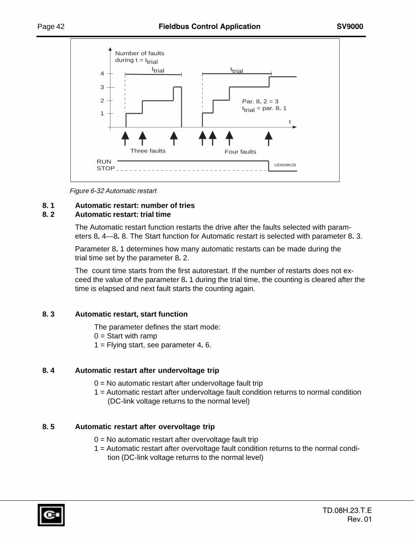
8. 1 Automatic restart: number of tries8. 2 Automatic restart: trial time
The Automatic restart function restarts the drive after the faults selected with param-eters 8. 4—8. 8. The Start function for Automatic restart is selected with parameter 8. 3.
Parameter 8. 1 determines how many automatic restarts can be made during thetrial time set by the parameter 8. 2.
The count time starts from the first autorestart. If the number of restarts does not ex-ceed the value of the parameter 8. 1 during the trial time, the counting is cleared after thetime is elapsed and next fault starts the counting again.
8. 3 Automatic restart, start function
The parameter defines the start mode:0 = Start with ramp1 = Flying start, see parameter 4. 6.
8. 4 Automatic restart after undervoltage trip
0 = No automatic restart after undervoltage fault trip1 = Automatic restart after undervoltage fault condition returns to normal condition
(DC-link voltage returns to the normal level)
8. 5 Automatic restart after overvoltage trip
0 = No automatic restart after overvoltage fault trip1 = Automatic restart after overvoltage fault condition returns to the normal condi-
tion (DC-link voltage returns to the normal level)
4
3
2
1
ttrial ttrial
Par. 8. 2 = 3ttrial = par. 8. 1
t
UD009K25
Three faults Four faults
RUNSTOP
Number of faultsduring t = ttrial
Figure 6-32 Automatic restart
TD.08H.23.T.ERev. 01

SV9000 Fieldbus Control Application Page 43
8. 6 Automatic restart after overcurrent trip
0 = No automatic restart after overcurrent fault trip1 = Automatic restart after overcurrent faults
8. 7 Automatic restart after reference fault trip
0 = No automatic restart after reference fault trip1 = Automatic restart after analog current reference signal (4—20 mA) returns to
the normal level (>4 mA)
8. 8 Automatic restart after over-/undertemperature fault trip
0 = No automatic restart after temperature fault trip1 = Automatic restart after heatsink temperature has returned to its normal levelbetween -10°C—+75°C.
Torque control
Torque control can be activated either by setting parameter 6.1 to torque control or withdigital input DIA3 (parameter 2.2=10). The torque reference source is selected with pa-rameter 9.1 and reference scaling with parameters 9.2 and 9.3.
9.1 Torque reference selection
Defines the source for torque reference value:
0 = None1 = V
in
2 = Iin
9.2 Torque reference scaling bias9.3 Torque reference scaling gain
The additional scaling function can be used for scaling the torque reference. The torquereference is always fed to the torque controller even if it is not activated.
Tref. out
= gain × Tref. in
+ bias
9.4 TC time constant
Defines the time constant for the torque controller. A short time constant means fast re-sponse.
9.5 TC min. control limit
Defines frequency limit below which the drive operates normally in frequency control mode.
The internal torque calculation is inaccurate at low speeds (< nominal slip of the motor). Itis recommended to operate in frequency control operation mode at low speeds.
The reference value in frequency controlled operation mode is selected with parameter 1.5.
TD.08H.23.T.ERev. 01
Page 44 Fieldbus Control Application SV9000
Fieldbus control
Fieldbus control can be activated with parameter 10.1. Then both the frequency orspeed reference and the Start/Stop and Reverse control comes from the fieldbus.
The first two parameters in group 10 concern all fieldbuses. Parameters 10.3 - 10.4 arefor Modbus and N2, 10.5-10.6 for Modbus only, 10.7-10.13 for Profibus only, and 10.14for LonWorks only.
10. 1 Fieldbus control
Defines the active control source:
0: control via I/O terminals1: control via Fieldbus board
10.2 DIC1 function
0: Fieldbus control, contact open = Active control source I/O terminalscontact closed = Active control source the Fieldbus
board
1: External Fault, closing contact = Fault is shown and motor is stoppedwhen the input is active
Parameters 10.3 - 10.6 for Modbus/N2 protocol only
10.3 Slave address
Defines slave device address. Maximum value for this parameter is 247 andminimum is 1.
10.4 Baud Rate
1: 300 baud2: 600 baud3: 1200 baud4: 2400 baud5: 4800 baud6: 9600 baud7: 19200 baud
10.5 Parity type
0: None1: Even2: Odd
TD.08H.23.T.ERev. 01
SV9000 Fieldbus Control Application Page 45
10.6 Modbus time-out
The Modbus time-out defines how long the Fieldbus board waits for a message from amaster device and is specified in seconds.
Time can be set between 0 - 3600 s. Time 0 s = No time-out
Parameters 10.7 to 10.13 for Profibus DP protocol only
10.7 Profibus slave address
Defines slave device address. Maximum value for this parameter is 126 and minimum 2.
10.8 Profibus baud rate
1: 9.6 kbaud2: 19.2 kbaud3: 93.75 kbaud4: 187.5 kbaud5: 500 kbaud6: 1.5 Mbaud7: 3 Mbaud8: 6 Mbaud9: 12 Mbaud10: AUTO (Automatic baud rate select)
10.9 Profibus PPO Type
Selection of Profibus PPO type.
1: PPO 1 (Parameter data 8 bytes, Control data 4 bytes)2: PPO 2 (Parameter data 8 bytes, Control data 4 bytes)3: PPO 3 (Control data 4 bytes)4: PPO 4 (Control data 12 bytes)
10.10 Profibus process Data 110.11 Profibus process Data 210.12 Profibus process Data 310.13 Profibus process Data 4
Selection of Profibus process data source.
Value 1...22 Number of actual value (= n1 ... n22 in monitor page)
99 Active fault code
Parameter 10.14 for LonWorks protocol only
10.14 LonWorks service button
Changing the value of this parameter from 0 to 1 or vice versa and pressing the Enterbutton causes the unique LonWorks ID number to be sent to the network.
TD.08H.23.T.ERev. 01
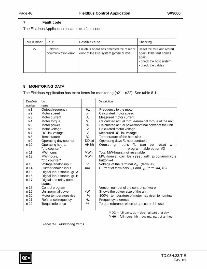
Page 46 Fieldbus Control Application SV9000
7 Fault code
The Fieldbus Application has an extra fault code:
8 MONITORING DATA
The Fieldbus Application has extra items for monitoring (n21 - n22). See table 8-1
DataData Uni t Descriptionnumber namen 1 Output frequency Hz Frequency to the motorn 2 Motor speed rpm Calculated motor speedn 3 Motor current A Measured motor currentn 4 Motor torque % Calculated actual torque/nominal torque of the unitn 5 Motor power % Calculated actual power/nominal power of the unitn 6 Motor voltage V Calculated motor voltagen 7 DC-link voltage V Measured DC-link voltagen 8 Temperature °C Temperature of the heat sinkn 9 Operating day counter DD.dd Operating days 1), not resettable
n 10 Operating hours, HH.hh Operating hours 2), can be reset with"trip counter" programmable button #3
n 11 MW-hours MWh Total MW-hours, not resettablen 12 MW-hours, MWh MW-hours, can be reset with programmable
"trip counter" button #4n 13 Voltage/analog input V Voltage of the terminal Vin+ (term. #2)n 14 Current/analog input mA Current of terminals Iin+ and Iin- (term. #4, #5)n 15 Digital input status, gr. An 16 Digital input status, gr. Bn 17 Digital and relay output
statusn 18 Control program Version number of the control softwaren 19 Unit nominal power kW Shows the power size of the unitn 20 Motor temperature rise % 100%= temperature of motor has risen to nominaln 21 Reference frequency Hz Frequency referencen 22 Torque reference % Torque reference when torque control in use
1) DD = full days, dd = decimal part of a day2) HH = full hours, hh = decimal part of an hour
Table 8-1 Monitoring items
rebmuntluaF tluaF esuacelbissoP gnikcehC
72 subdleiFrorrenoitacinummoc
roteserehtdetcetedsahdraobsubdleiF)reyallacisyhp(metsyssuBehtfororre
tratserdnatluafehtteseRsemoctluafehtfI.niaga
:niagametsystsohehtkcehc-
selbacehtkcehc-
TD.08H.23.T.ERev. 01
Top Related