


Languages
Pages
Legal


1 Kayode Adeniji 2015 (ExCiS (v2))
Academic Department of Critical Care Queen Alexandra Hospital (DCCQ)
Extra corporeal circuit simulator (ExCiS)

2 Kayode Adeniji 2015 (ExCiS (v2))
Contents Introduction ...................................................................................................................................... 3
Package Contents .............................................................................................................................. 4
Getting started .................................................................................................................................. 6
Assembly ........................................................................................................................................... 6
Filling the volume capacitor ............................................................................................................. 20
Emptying the volume capacitor ....................................................................................................... 22
3 Kayode Adeniji 2015 (ExCiS (v2))
Introduction
Department of Critical Care Queen Alexandra Hospital
Southwick Hill, Cosham Portsmouth, PO6 3LY Office: 02392286844
Fax: 02392286967 E-mail: [email protected]
Twitter: @kadeniji1 Extra corporeal circuits are incorporated into many forms of advanced organ support systems e.g. Extra Corporeal Lung Assist (ECLA), Renal Replacement Therapy. An important part of their implementation in any critical care setting is to develop the governance protocols that ensure the patient safety against the potential catastrophic consequences of circuit complications e.g. disconnection. An inherent component of this is simulation to build team work and mitigate the effect of human factors. There are high definition simulators housed in simulation suites available on the market costing several thousand pounds. These systems are designed and have the capability of delivering a more real-life experience. However, when the issues are related to teaching the mechanics of safe aseptic cannulation, circuit set up, circuit connection and manipulation, simple circuit related troubleshooting and practising circuit complication drills, that level of complexity may not be wanted or required. When a simulator was required to commission the ILA Activve® extracorporeal circuit purchased to use on patients with respiratory failure in the Critical Department at Queen Alexandra Hospital I developed the Extra corporeal circuit sumulator (ExCiS). It represents a cheap alternative to the high fidelity type simulators. It is a re-useable blood volume capacitor that can be repeatedly cannulated and used to demonstrate the setup and running of any kind of extracorporeal circuit (ECMO, ECCO2R, Cardiac Bypass, Renal dialysis, etc.) with components that can be purchased at any local hardware store and put together in your garage. Though it was designed for simulation on the ilA Activve® an extracorporeal (primarily Carbon dioxide removal (ECCO2R)) device that requires simultaneous changes in ventilation and circuit modulation; it can be utilised to model the team-work and procedures needed to manage any extra corporeal circuit and is eminently configurable to the requirements at your institution. This diagramatic instruction manual is made available under the FOAMed ethos and can be downloaded free from the Queen Alexandra Hospital Critical Care website (www.portsmouthicu.com). Due to to the support of the Portsmouth NHS Trust Innovation partnership I can also send out the components in a kit that you can assemble though this will necessarily result in a cost to you. I encourage you to alter the system as you require. I still do. Enjoy. Kayode Adeniji BMedSci, MSc, MRCP, FFICM
4 Kayode Adeniji 2015 (ExCiS (v2))
Package Contents
*See pictures below and familiarise yourself with components before assembling*
A. LA Head complete (Skull and Skin) – Laerdal Medical Corp (REF 020920) B. 110mmx3mmx1000mm Clear Acrylic Tube (Extruded) - (REF 110/104) and 2 x Floplast Terracotta Coupling 110mmx133mm (REF 5055149907104) C. Floplast 87.5degree Terracotta bend 110mmx151mm (REF 5055149907333) D. Floplast Terracotta Socket plug 110mmx123mm (REF 5055149907364) E. Floplast Black Pipe clips (REF 5055149920820) F. 1 x size 7 Portex Tracheal Tube – (REF 100/199/070) G. 82 cm Meditech elephant tubing – 3 x 2 corrugated sections H. 1 x T-Piece 22M-22M/15F-22M (REF 1980000) I. 2 x Elbow-Piece 22F-22M (REF1992) J. 2 x Connector 22M-22M (REF 1960) K. 2 x 1L reservoir bags (REF 2810000) L. 25mm Rubber Snap-in blanking plugs (NB. Ext. Dia 29.2mm, Int. Dia 25mm) (REF 380543243357) M. Black Cable ties N. 2m Length of garden hose pipe O. 2 x Grey outlet hose ends 22 or 25mm P. 1 x Roll electrical tape (Not supplied) Q. Drill with 25mm circular hole saw bit (Not supplied) *only required if assembling w/o kit* (Not supplied) *These reference numbers refer to items available on-line and at my local hardware store – they
only represent a guide as to the materials that can be used. I encourage you to experiment*

5 Kayode Adeniji 2015 (ExCiS (v2))
C
B
D
E
A
F
G
I
J
K
M
H M
L
N

6 Kayode Adeniji 2015 (ExCiS (v2))
Getting started Please read and make sure you understand the instructions and review the illustrating pictures in each step before assembling the EXCiS in a logical step wise manner.
Assembly (i) **This step applies only if you purchase parts on your own** Drill two 25mm holes using a circular hole saw (ensure you create a pilot hole before using the core drill bit (a) 42 cm from the L end and (b) 31 cm from the H to form B end in part B (Clear acrylic tube with 2 Coupling attachments on either side (NB. The fittings are snug)
25 mm Holes
L H
7 Kayode Adeniji 2015 (ExCiS (v2))
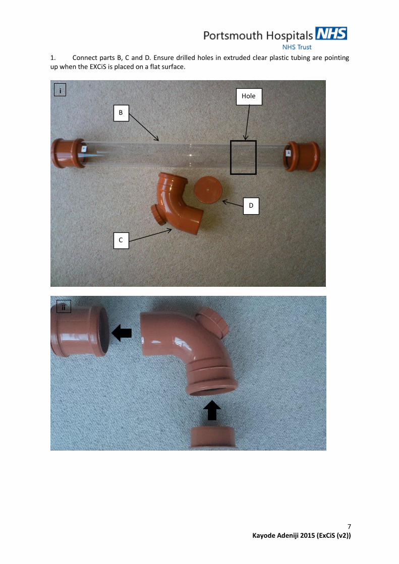
1. Connect parts B, C and D. Ensure drilled holes in extruded clear plastic tubing are pointing up when the EXCiS is placed on a flat surface.
C
C
D
B
Hole i
ii
8 Kayode Adeniji 2015 (ExCiS (v2))
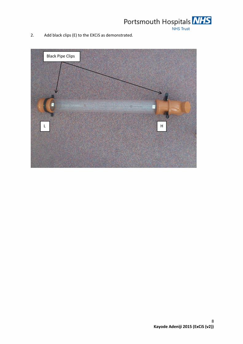
2. Add black clips (E) to the EXCiS as demonstrated.
L H
Black Pipe Clips

9 Kayode Adeniji 2015 (ExCiS (v2))
3. Join 2 Cable ties (M) together and attach around Black clips (E). Ensure they are pulled as tight as possible on both sides.
2 cable ties joined
together
Pull
Pull
i
ii
iii

10 Kayode Adeniji 2015 (ExCiS (v2))
4. Connect 3 pieces of Corrugated tubing (G), T-Piece (H), 2 Elbow-Pieces (I) and 2 connectors (J) to assemble the demonstrated structure below. Place a strip of electrical tape around each corrugated tube join.
I
H G
J
J
Electrical tape
i
ii
iii

11 Kayode Adeniji 2015 (ExCiS (v2))
5. Remove the rubber face from the LA Head Complete (A).
A
12 Kayode Adeniji 2015 (ExCiS (v2))
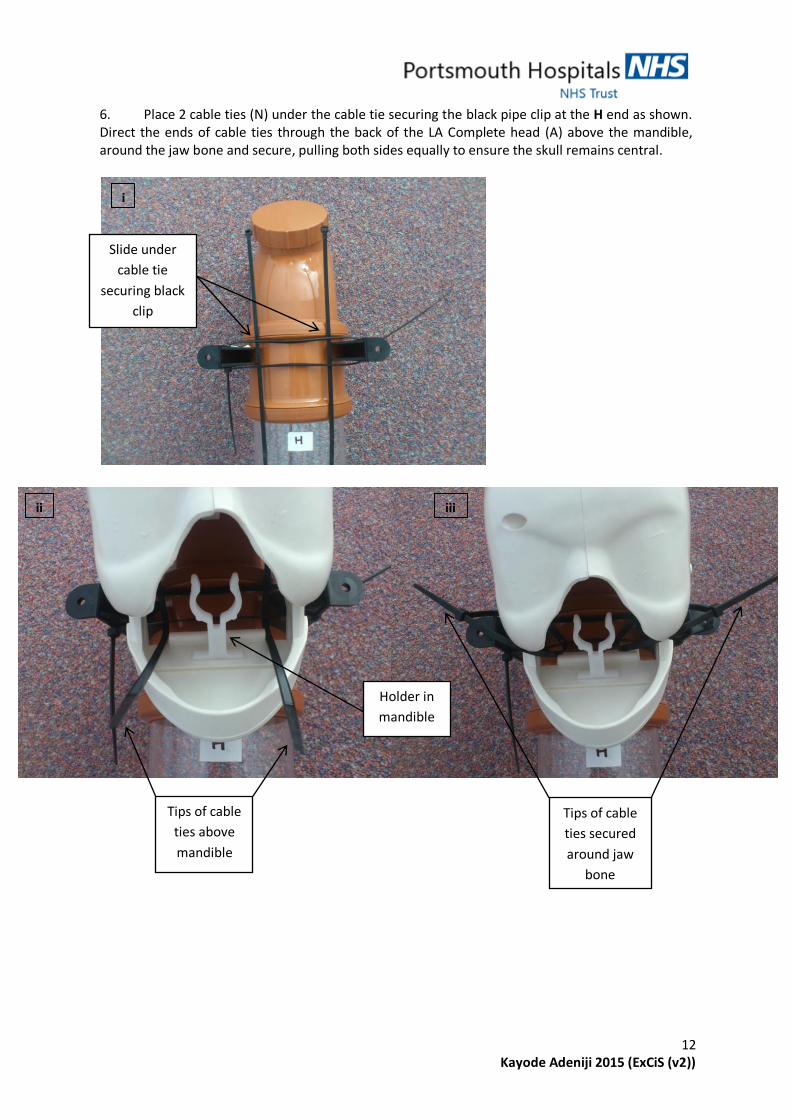
6. Place 2 cable ties (N) under the cable tie securing the black pipe clip at the H end as shown. Direct the ends of cable ties through the back of the LA Complete head (A) above the mandible, around the jaw bone and secure, pulling both sides equally to ensure the skull remains central.
Tips of cable
ties above
mandible
Slide under
cable tie
securing black
clip
Tips of cable
ties secured
around jaw
bone
Holder in
mandible
i
ii iii

13 Kayode Adeniji 2015 (ExCiS (v2))
7. Place the corrugated tubing structure assembled in step 4. with the single pipe aspect coming through the mouth of the skull and arrange the rest of the structure to lie on both sides of the under the head piece as shown.
Gj hhj khj khj khj ohj kl l kj kl nk. ; .
Corrugated
tubing coming
through mouth of
skull
Holder in
mandible
i
ii iii

14 Kayode Adeniji 2015 (ExCiS (v2))
8. Join 2 cable ties together making sure to maintain as much length as possible and slip 1 end between the mandible of the skull and the Acrylic tube. Bring both sides of the corrugated tubing up on both sides of the Acrylic piece and tighten gently ensuring that the corrugated tubing is trapped in the ‘triangular’ space made by the cable tie joins against the acrylic tube.
Corrugated tubing
brought into
circumference of
cable ties
i ii
iii
15 Kayode Adeniji 2015 (ExCiS (v2))
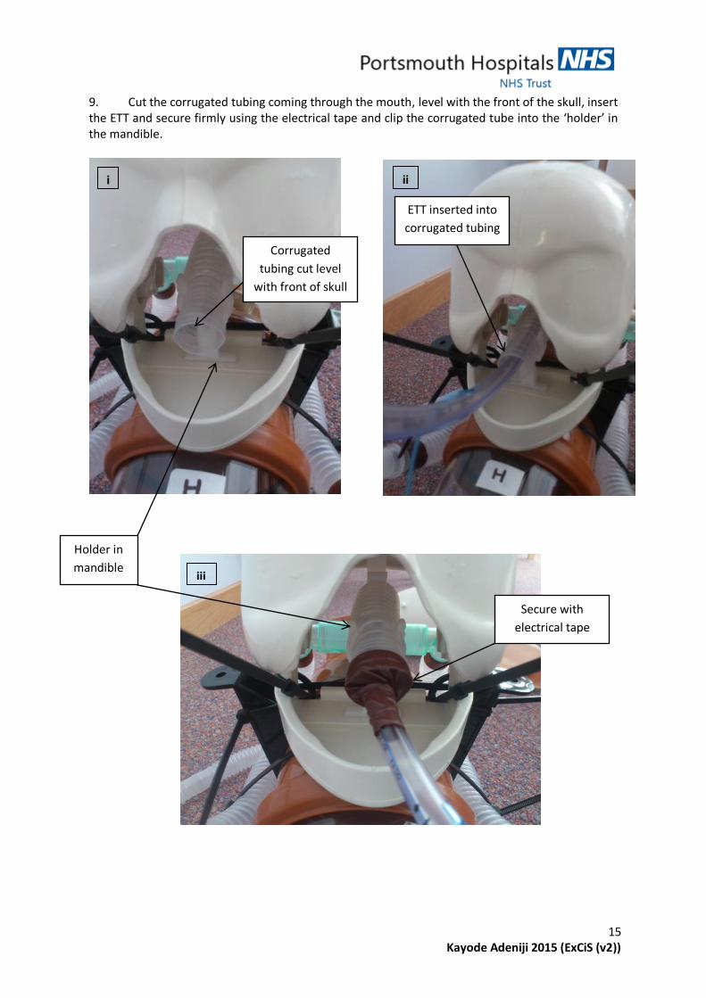
9. Cut the corrugated tubing coming through the mouth, level with the front of the skull, insert the ETT and secure firmly using the electrical tape and clip the corrugated tube into the ‘holder’ in the mandible.
ETT inserted into
corrugated tubing
Corrugated
tubing cut level
with front of skull
Secure with
electrical tape
Holder in
mandible
i ii
iii

16 Kayode Adeniji 2015 (ExCiS (v2))
10. Cut off all the excess cable tie tips.
Excess plastic
from cable ties
removed

17 Kayode Adeniji 2015 (ExCiS (v2))
11. Push the ETT and balloon inflation port through the mouth of the skin cover of the LA Complete (A) and refix over the ears. (NB. The mandible aspect of the skull does remain exposed). The ETT tube can then be shortened if necessary.
Pass ETT through
mouth of skin
cover
Skin fixed onto
skull through
fitting in ears
Part of mandible
remains exposed
i
ii

18 Kayode Adeniji 2015 (ExCiS (v2))
12. Attach the green rubber 1 Litre reservoir bags (K) (NB different bags e.g. 500mls and different end attachment can be used e.g. HME filters depending on level on pulmonary compliance you wish to simulate). The ETT balloon will need to be inflated as usual when attached to a mechanical ventilator.
K
19 Kayode Adeniji 2015 (ExCiS (v2))
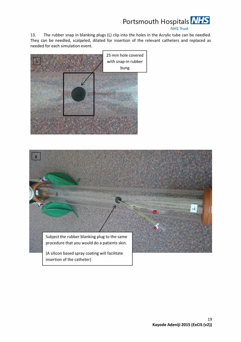
13. The rubber snap in blanking plugs (L) clip into the holes in the Acrylic tube can be needled. They can be needled, scalpeled, dilated for insertion of the relevant catheters and replaced as needed for each simulation event.
25 mm hole covered
with snap-in rubber
bung
i
ii
Subject the rubber blanking plug to the same
procedure that you would do a patients skin.
(A silicon based spray coating will facilitate
insertion of the catheter)

20 Kayode Adeniji 2015 (ExCiS (v2))
Filling the volume capacitor 1. Insert cut end of garden hose (N) into grey outlet hose end (O) and secure with electrical tape.
Attach 1 end to tap and place other end into 1 of the holes in the acrylic tube. (NB. When filling ensure the other hole in acrylic tube is open to allow air to escape and watch the water level)
Secure join with
electrical tape
Insert cut end of
garden hose into
grey outlet hose end
i
ii
‘Air hole’ - Initially left open to allow air to
escape during filling process
Cap off ‘Filling hole’ with rubber blanking plug
based on water level and top up through here
after.
Filling hole

21 Kayode Adeniji 2015 (ExCiS (v2))
22 Kayode Adeniji 2015 (ExCiS (v2))
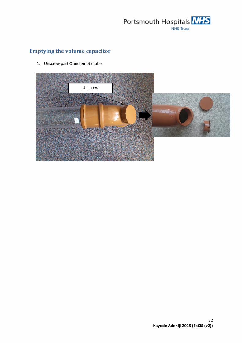
Emptying the volume capacitor
1. Unscrew part C and empty tube.
Unscrew
Top Related