


Languages
Pages
Legal

AC SERVO DRIVES
SERVOMOTOR TYPE: SGMAH– , SGMPH– , SGMGH– , SGMSH– , SGMUH–
SERVOPACK TYPE : SGDH–
YASKAWA
SERIES
LITERATURE NO. KAE-S800-32D
JQA-0386,-0422
Certified by ISO 9001
YASKAWA

Adva
ntage 3
Adva
ntage 2
Adva
ntage 1
32
"He receives the ball and makes a quick, accurate pass. No. 2 fakes
out his opponent. He shoots! He scores! What great team work!
What a combo!!" The fans are spell-bound by such world-class
plays that require quick speed, great accuracy, and good judgment.
Σ-II series can be the key player to increase your machine's
performance and productivity. Servo drives must be more
responsive, more quick, and more accurate than world class
athletes. Together with our additional boards, our stars can use
amazing combination plays regardless of your playing conditions.
Features
Servomotor-SERVOPACK Combinations
Type Designation
Configurations
Connection Diagrams
Servomotor Specifications
SERVOPACK Specifications
Servomotor Dimensions
SERVOPACK Dimensions
Function Description
Function Setup and Alarms
Options
4
6
8
9
12
15
22
24
26
28
32
34
CONTENTS
Flexible Enough to Adapt to Different Playing Conditions
World topperformance
Your production will be increased byΣ-II and bring your machine potentialto its highest performance. Outstanding rapid response is achieved with 1/3settling time due to 1/2 CPU operation
time and upgraded new control algorithms. 6000min–1 motor is newly
available.
One on oneset up/maintenance
Easy to start up your sophisticated system in ashort time. Online auto-tuning
automatically adjusts servo drives in accordance with your machine's characteristics. Also, isolated main and control circuit
power supplies and alarm traceback function enable easy maintenance.
Flexible combination
Combine one of our full lineup SERVOPACKs and an option board, it plays an important part of network and even higher system performance.Moreover, conformance to international standards assures your operation
standards worldwide.
PAGE
Full conformance to markings
as well as
4
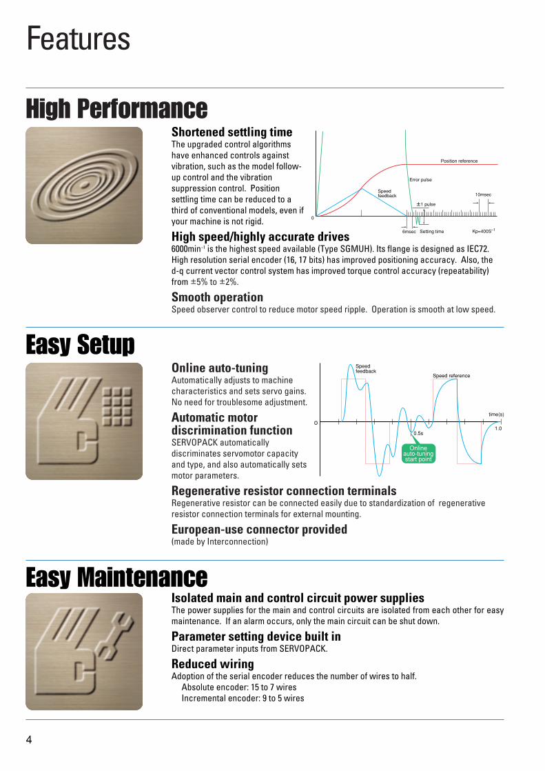
Shortened settling timeThe upgraded control algorithmshave enhanced controls againstvibration, such as the model follow-up control and the vibrationsuppression control. Positionsettling time can be reduced to athird of conventional models, even ifyour machine is not rigid.
High speed/highly accurate drives6000min–1 is the highest speed available (Type SGMUH). Its flange is designed as IEC72.High resolution serial encoder (16, 17 bits) has improved positioning accuracy. Also, the d-q current vector control system has improved torque control accuracy (repeatability)from ±5% to ±2%.
Smooth operationSpeed observer control to reduce motor speed ripple. Operation is smooth at low speed.
Online auto-tuningAutomatically adjusts to machinecharacteristics and sets servo gains.No need for troublesome adjustment.
Automatic motor discrimination functionSERVOPACK automaticallydiscriminates servomotor capacityand type, and also automatically setsmotor parameters.
Regenerative resistor connection terminalsRegenerative resistor can be connected easily due to standardization of regenerativeresistor connection terminals for external mounting.
European-use connector provided(made by Interconnection)
Features
High Performance
Easy Setup
Isolated main and control circuit power suppliesThe power supplies for the main and control circuits are isolated from each other for easymaintenance. If an alarm occurs, only the main circuit can be shut down.
Parameter setting device built inDirect parameter inputs from SERVOPACK.
Reduced wiringAdoption of the serial encoder reduces the number of wires to half.
Absolute encoder: 15 to 7 wiresIncremental encoder: 9 to 5 wires
Easy Maintenance
Speedfeedback
Position reference
Error pulse
±1 pulse
10msec
Setting time6msec
0
Kp=400S–1
Speedfeedback
Speed reference
Onlineauto-tuningstart point
0
0.5s1.0
time(s)
5
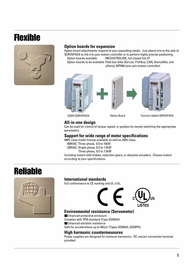
Option boards for expansionOption board attachments respond to your expanding needs. Just attach one to the side ofSERVOPACK to link it to your motion controller or to perform highly precise positioning.
Option boards available : MECHATROLINK, full closed link I/FOption boards to be available: Field bus links (Sercos, Profibus, CAN, DeviceNet, and
others), MP940 (one-axis motion controller)
All-in-one designCan be used for control of torque, speed, or position by merely switching the appropriateparameters.
Support for wide range of motor specifications400V class model lineups available as well as 230V class.
400VAC: Three-phase, 0.5 to 15kW230VAC: Single-phase, 0.3 to 1.5kW
Three-phase, 0.5 to 7.5kWIncluding motors with brakes, reduction gears, or absolute encoders. Choose motorsaccording to your specifications.
Flexible
International standardsFull conformance to CE marking and UL /cUL.
Environmental resistance (Servomotor)Enhanced protective enclosureComplies with IP55 standard (Type SGMAH)Enhanced vibration resistanceSafe for accelerations up to 49m/s2 (Types SGMAH, SGMPH).
High harmonic countermeasuresPower supplies are designed for minimum harmonics. DC reactor connection terminalprovided.
Reliable
SGDH SERVOPACK Option Board Function Added SERVOPACK
Servomotor
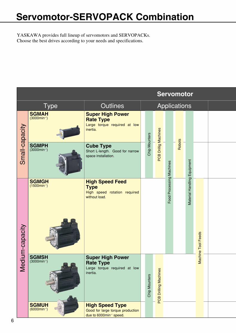
SGMAH(3000min–1)
SGMPH(3000min–1)
SGMGH(1500min–1)
SGMSH(3000min–1)
SGMUH(6000min–1)
Type Outlines Applications
Sm
all-c
apac
ityM
ediu
m-c
apac
ity
Cube TypeShort L-length. Good for narrow space installation.
Super High Power Rate TypeLarge torque required at low inertia.
High Speed Feed TypeHigh speed rotation required without load.
Super High Power Rate TypeLarge torque required at low inertia.
High Speed TypeGood for large torque production due to 6000min–1 speed.
Chi
p M
ount
ers
PC
B D
rillin
g M
achi
nes
6
Servomotor-SERVOPACK Combination
YASKAWA provides full lineup of servomotors and SERVOPACKs.Choose the best drives according to your needs and specifications.
Chi
p M
ount
ers
PC
B D
rillig
Mac
hine
s
Rob
ots
Foo
d P
roce
ssin
g M
achi
nes
Mac
hine
Too
l Fee
ds
Mat
eria
l Han
dlin
g E
quip
men
t
0.45kW0.85kW1.3kW1.8kW2.9kW4.4kW5.5kW7.5kW
05DE10DE15DE20DE30DE
1EDE1ADE75DE60DE50DE
Future larger0.45kW0.85kW1.3kW1.8kW2.9kW
15kW11kW7.5kW5.5kW4.4kW
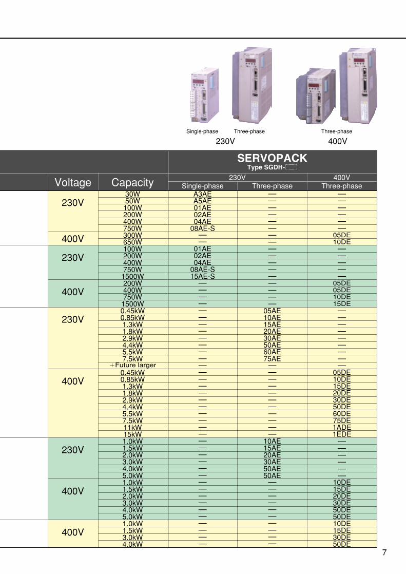
SERVOPACKType SGDH-
Voltage
230V
Capacity 230V 400VThree-phaseSingle-phase
30W50W
100W200W400W750W300W650W100W200W400W750W
1500W200W400W750W
1500W
10DE15DE20DE30DE50DE
15DE10DE
30DE
––––––
50DE
50DE
1.0kW1.5kW2.0kW3.0kW4.0kW5.0kW1.0kW1.5kW2.0kW3.0kW4.0kW5.0kW1.0kW1.5kW3.0kW4.0kW
Three-phase
7
Single-phase Three-phase Three-phase
230V 400V
––––––––––––––––––
–––––
A3AEA5AE01AE02AE
01AE02AE04AE
08AE-S15AE-S
––––––––––
–––––
–
–
04AE08AE-S
–
05AE10AE15AE20AE30AE50AE60AE75AE–––––
––––––
10AE15AE20AE30AE50AE50AE
–––
––
––
–––
–––
––––
––
––
––
––––
––––––
–
–
05DE
–
05DE
–
––
–
10DE
–
05DE
–
–
–
10DE15DE–––
230V
400V
400V
230V
400V
230V
400V
400V
8
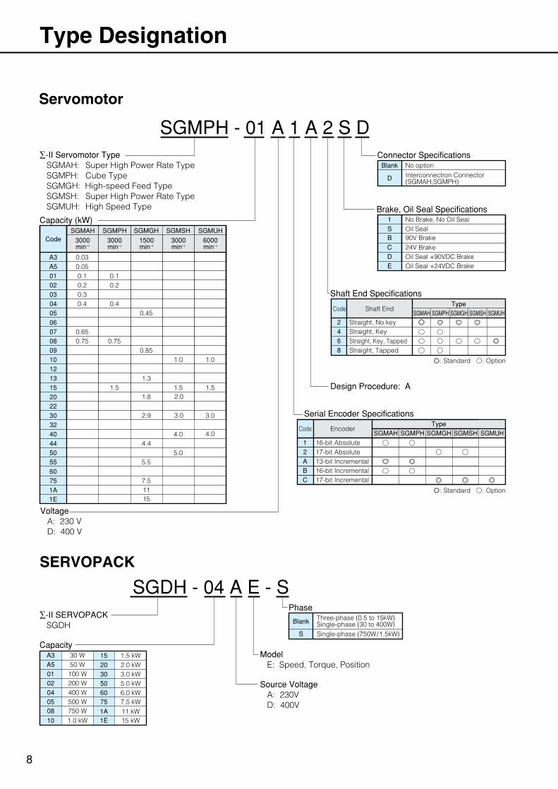
Type Designation
Capacity (kW)SGMGH SGMSH SGMUH
1500min–1
3000min–1
6000min–1
SGMAH
3000min–1
SGMPH
3000min–1
A3 0.030.050.10.20.3
0.10.2
0.4 0.40.45
0.750.65
0.750.85
3.0
1.3
2.01.8
2.9
1.5
1.01.0
1.51.5
3.0
4.0
A501020304050607080910121315202230
4.45.0
7.51115
4.0
5.5
324044505560751A1E
A3 30 W50 W100 W200 W400 W
750 W
A5010204
08
1.5 kW2.0 kW3.0 kW5.0 kW
7.5 kW
15203050
75
1.0 kW1011 kW1A15 kW1E
500 W056.0 kW60
Code
Blank
S Single-phase (750W/1.5kW)
Three-phase (0.5 to 15kW)Single-phase (30 to 400W)
Servomotor
D
Blank
Interconnectron Connector(SGMAH,SGMPH)
No optionConnector Specifications
1SB
CD
No Brake, No Oil Seal
E
Oil Seal90V Brake24V BrakeOil Seal +90VDC BrakeOil Seal +24VDC Brake
Brake, Oil Seal Specifications
Shaft End Specifications
Design Procedure: A
TypeSGMAH SGMPH SGMGH SGMSH SGMUH
2468
Straight, No key
Shaft EndCode
EncoderCode
Straight, KeyStraight, Key, TappedStraight, Tapped
: Standard : Option
: Standard : Option
Serial Encoder SpecificationsType
SGMAH SGMPH SGMGH SGMSH SGMUH1 16-bit Absolute2 17-bit AbsoluteA 13-bit IncrementalB 16-bit IncrementalC 17-bit Incremental
SGMPH - 01 A 1 A 2 S D∑-II Servomotor Type SGMAH: Super High Power Rate Type SGMPH: Cube Type SGMGH: High-speed Feed Type SGMSH: Super High Power Rate Type SGMUH: High Speed Type
∑-II SERVOPACK SGDH
CapacityModel E: Speed, Torque, Position
Source Voltage A: 230V D: 400V
Voltage A: 230 V D: 400 V
SERVOPACK
SGDH - 04 A E - SPhase
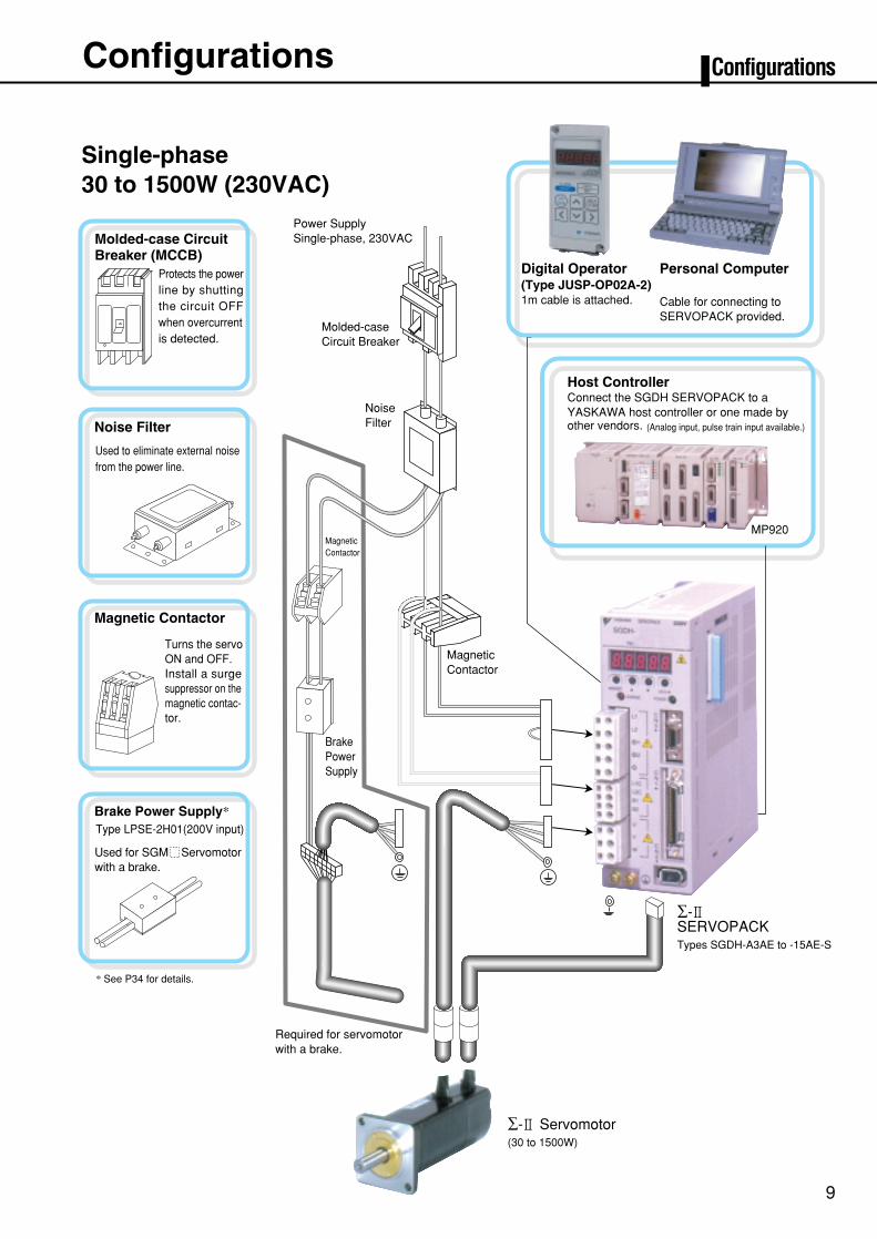
Single-phase 30 to 1500W (230VAC)
Magnetic Contactor
Host ControllerConnect the SGDH SERVOPACK to a YASKAWA host controller or one made byother vendors.
MP920
(Analog input, pulse train input available.)
Digital Operator(Type JUSP-OP02A-2)1m cable is attached.
Personal ComputerCable for connecting to SERVOPACK provided.
∑-2SERVOPACKTypes SGDH-A3AE to -15AE-S
∑-2 Servomotor(30 to 1500W)
* See P34 for details.
Protects the powerline by shutting the circuit OFF when overcurrent is detected.
Noise Filter
Magnetic Contactor
Brake Power Supply*
Used to eliminate external noisefrom the power line.
Turns the servoON and OFF.Install a surgesuppressor on themagnetic contac-tor.
Type LPSE-2H01(200V input)Used for SGM Servomotor with a brake.
Required for servomotorwith a brake.
Magnetic Contactor
BrakePowerSupply
Molded-case CircuitBreaker (MCCB)
NoiseFilter
Molded-caseCircuit Breaker
Power SupplySingle-phase, 230VAC
9
Configurations Configurations
10
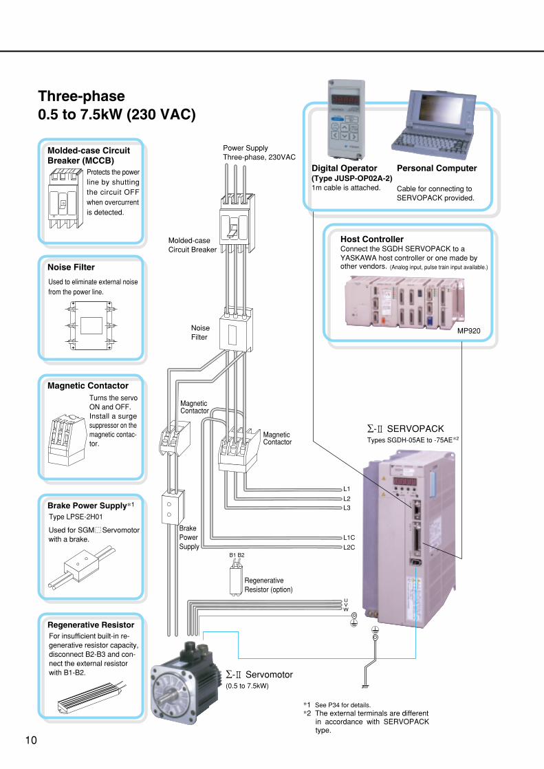
Three-phase 0.5 to 7.5kW (230 VAC)
(Analog input, pulse train input available.)
Digital Operator(Type JUSP-OP02A-2)1m cable is attached.
Personal ComputerCable for connecting to SERVOPACK provided.
*1 See P34 for details.*2 The external terminals are different in accordance with SERVOPACK type.
Power SupplyThree-phase, 230VAC
Molded-caseCircuit Breaker
NoiseFilter
∑-2 Servomotor(0.5 to 7.5kW)
Magnetic Contactor
BrakePowerSupply
RegenerativeResistor (option)
Magnetic Contactor
Protects the powerline by shutting the circuit OFF when overcurrent is detected.
Molded-case CircuitBreaker (MCCB)
Noise Filter
Magnetic Contactor
Brake Power Supply*1
Used to eliminate external noisefrom the power line.
Turns the servoON and OFF.Install a surgesuppressor on themagnetic contac-tor.
Type LPSE-2H01
Used for SGM Servomotor with a brake.
Regenerative ResistorFor insufficient built-in re-generative resistor capacity, disconnect B2-B3 and con-nect the external resistor with B1-B2.
Host ControllerConnect the SGDH SERVOPACK to a YASKAWA host controller or one made byother vendors.
MP920
∑-2 SERVOPACKTypes SGDH-05AE to -75AE
L3L2
L1
L2C
L1C
UVW
B1 B2
*2
11
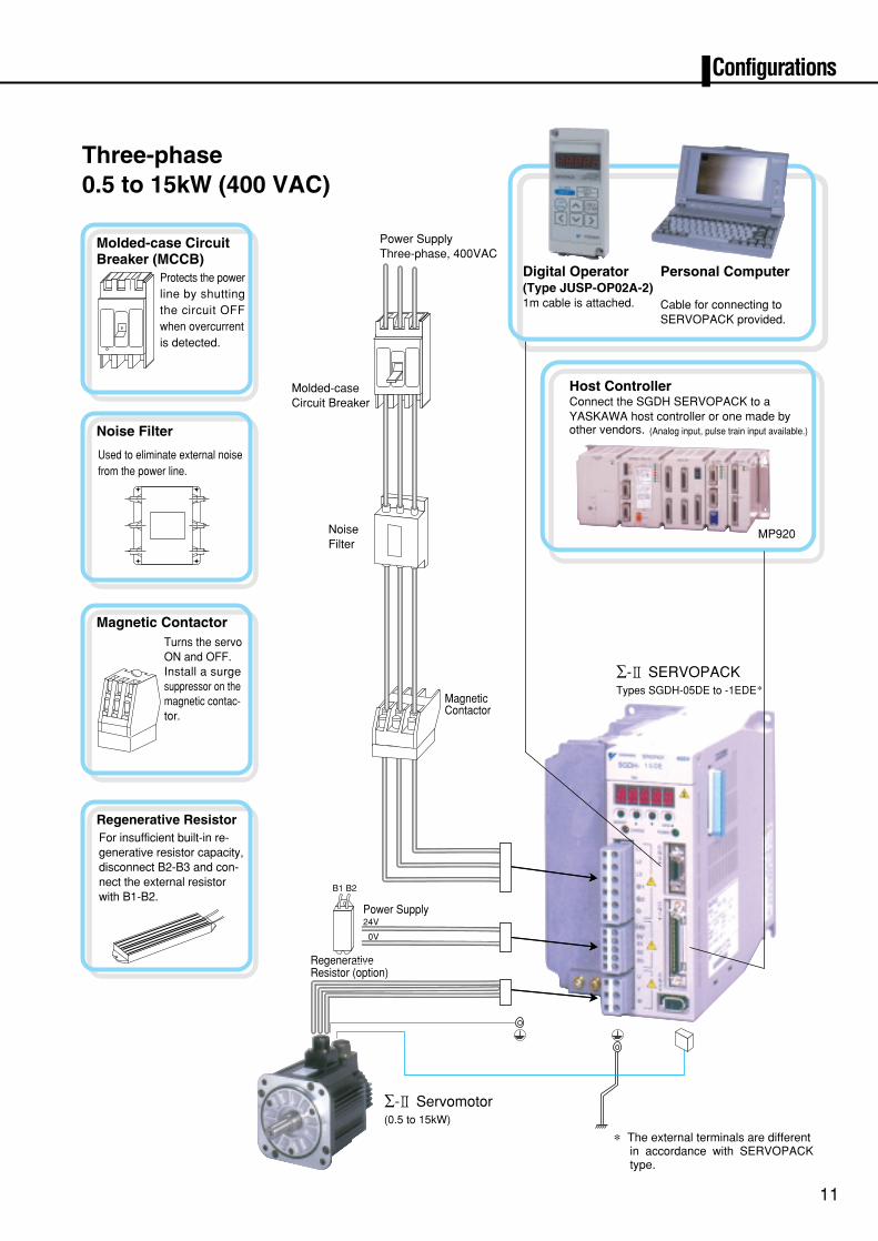
Three-phase 0.5 to 15kW (400 VAC)
Configurations
* The external terminals are different in accordance with SERVOPACK type.
RegenerativeResistor (option)
(Analog input, pulse train input available.)
Digital Operator(Type JUSP-OP02A-2)1m cable is attached.
Personal ComputerCable for connecting to SERVOPACK provided.
Power SupplyThree-phase, 400VAC
Molded-caseCircuit Breaker
NoiseFilter
∑-2 Servomotor(0.5 to 15kW)
Magnetic Contactor
Power Supply
Protects the powerline by shutting the circuit OFF when overcurrent is detected.
Molded-case CircuitBreaker (MCCB)
Noise Filter
Magnetic Contactor
Used to eliminate external noisefrom the power line.
Turns the servoON and OFF.Install a surgesuppressor on themagnetic contac-tor.
Host ControllerConnect the SGDH SERVOPACK to a YASKAWA host controller or one made byother vendors.
MP920
24V
0V
∑-2 SERVOPACKTypes SGDH-05DE to -1EDE*
Regenerative ResistorFor insufficient built-in re-generative resistor capacity, disconnect B2-B3 and con-nect the external resistor with B1-B2.
B1 B2
12
Connection Diagrams
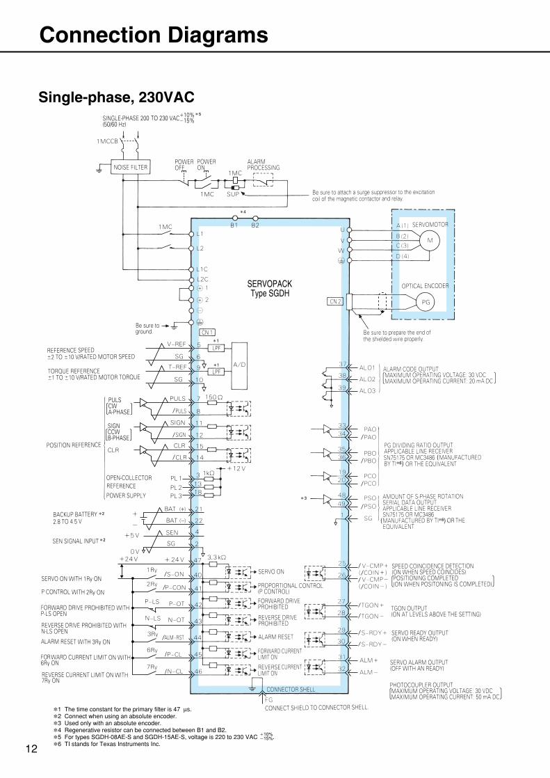
Single-phase, 230VAC
*1 The time constant for the primary filter is 47 µs.
*2 Connect when using an absolute encoder.
*3 Used only with an absolute encoder.
*4 Regenerative resistor can be connected between B1 and B2.
*5 For types SGDH-08AE-S and SGDH-15AE-S, voltage is 220 to 230 VAC .
*6 TI stands for Texas Instruments Inc.
10%15%
( *6)
(*6)
5
4
3
1
1
2
2
13
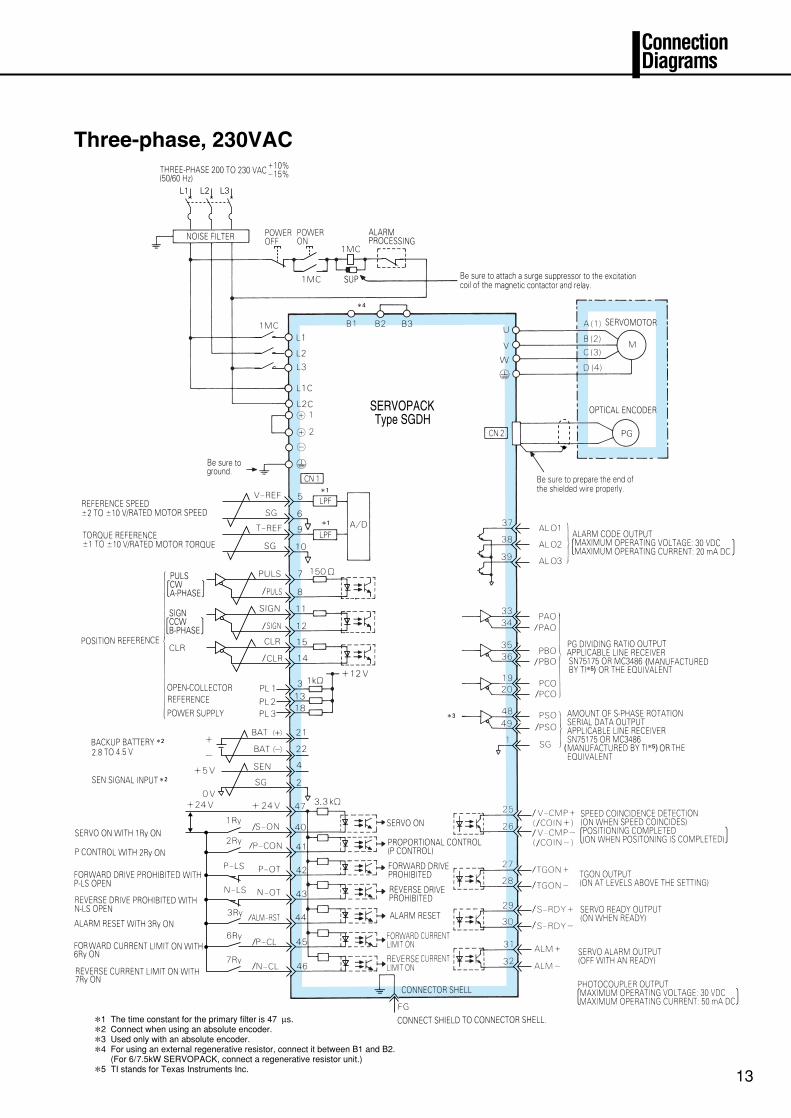
Three-phase, 230VAC
Connection Diagrams
*1 The time constant for the primary filter is 47 µs.
*2 Connect when using an absolute encoder.
*3 Used only with an absolute encoder.
*4 For using an external regenerative resistor, connect it between B1 and B2.(For 6/7.5kW SERVOPACK, connect a regenerative resistor unit.)
*5 TI stands for Texas Instruments Inc.
L1 L2 L3
4
( *5)
)*5(
1
1
3
2
2
14
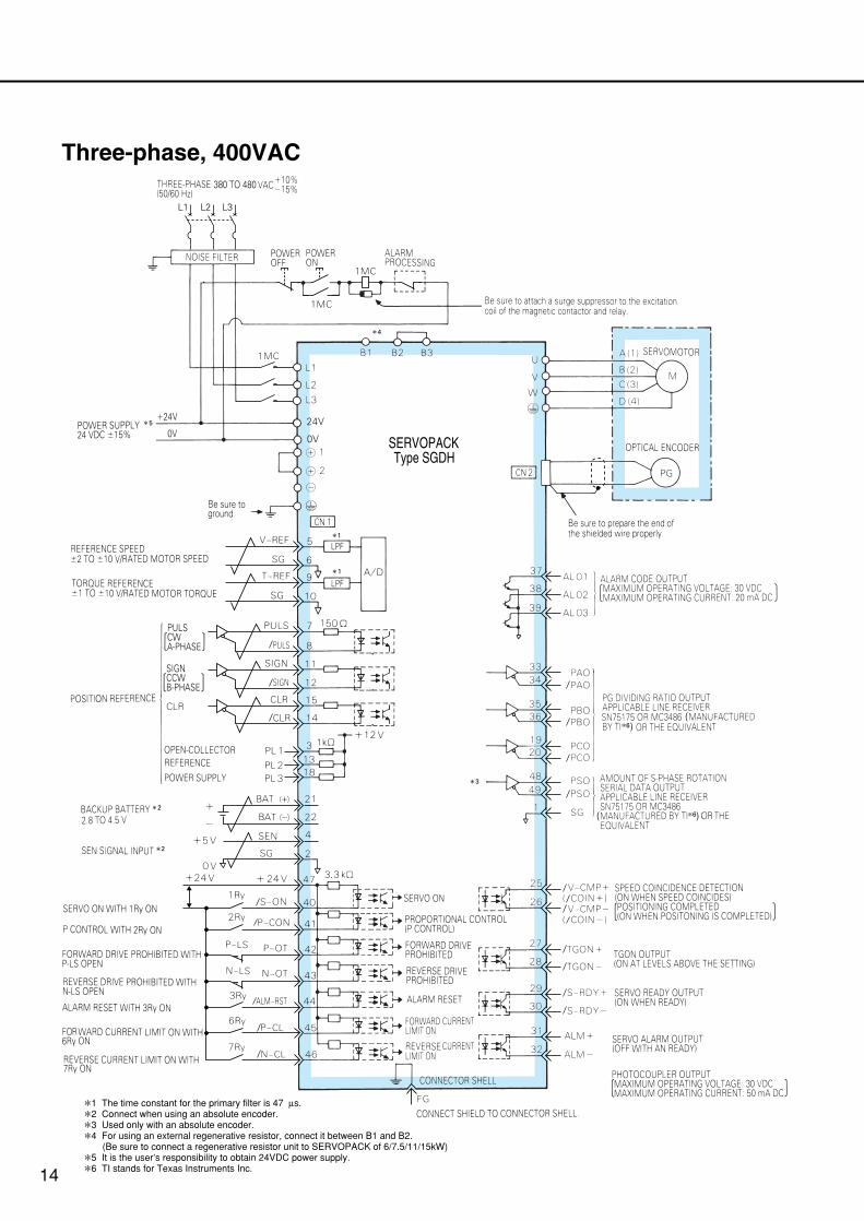
Three-phase, 400VAC
*1 The time constant for the primary filter is 47 µs.
*2 Connect when using an absolute encoder.
*3 Used only with an absolute encoder.
*4 For using an external regenerative resistor, connect it between B1 and B2. (Be sure to connect a regenerative resistor unit to SERVOPACK of 6/7.5/11/15kW)
*5 It is the user’s responsibility to obtain 24VDC power supply.
*6 TI stands for Texas Instruments Inc.
( *6)
(*6)
L1 L2 L3
4
5
1
1
2
2
3
15
SpecificationsType SGMAH
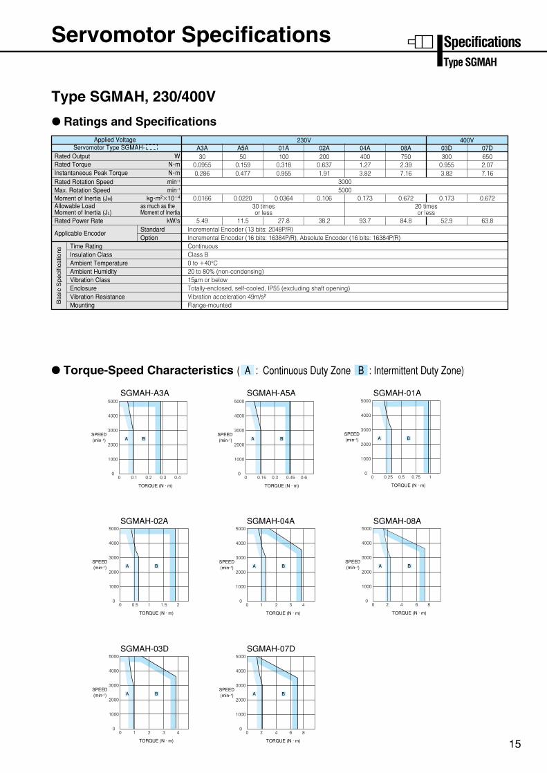
Type SGMAH, 230/400V
: Ratings and Specifications
: Torque-Speed Characteristics ( A : Continuous Duty Zone B : Intermittent Duty Zone)
SGMAH-A3A SGMAH-A5A SGMAH-01A
SGMAH-02A SGMAH-04A SGMAH-08A
4000
3000
2000
1000
00 0.1 0.2 0.3 0.4
5000
SPEED(min–1)
TORQUE (N · m)
A B
4000
3000
2000
1000
00 0.25 0.5 0.75 1
5000
SPEED(min–1)
TORQUE (N · m)
A B
4000
3000
2000
1000
00 1 2 3 4
5000
SPEED(min–1)
TORQUE (N · m)
A B
4000
3000
2000
1000
00 2 4 6 8
5000
SPEED(min–1)
TORQUE (N · m)
A B
4000
3000
2000
1000
00 0.5 1 1.5 2
5000
SPEED(min–1)
TORQUE (N · m)
A B
SGMAH-03D SGMAH-07D
4000
3000
2000
1000
00 2 4 6 8
5000
SPEED(min–1)
TORQUE (N · m)
A B
4000
3000
2000
1000
00 1 2 3 4
5000
SPEED(min–1)
TORQUE (N · m)
A B
4000
3000
2000
1000
00 0.15 0.3 0.45 0.6
5000
SPEED(min–1)
TORQUE (N · m)
A B
Servomotor Type SGMAH- Applied Voltage
Rated Output
Moment of Inertia (JM)
Rated Rotation Speed
Rated Power Rate
Applicable Encoder
Max. Rotation Speed
Rated TorqueInstantaneous Peak Torque
Allowable LoadMoment of Inertia (JL)
Time RatingInsulation ClassAmbient TemperatureAmbient HumidityVibration ClassEnclosureVibration ResistanceMounting
StandardOption
N •m
kg •m2104
as much as theMoment of Inertia
N •mW
min–1
min–1
kW/s
A3A30
0.09550.286
0.0166
5.49
30005000
30 timesor less
A5A50
0.1590.477
0.0220
11.5
20 timesor less
01A230V
1000.3180.955
0.0364
27.8
02A200
0.6371.91
0.106
38.2
04A4001.273.82
0.173
93.7
08A7502.397.16
0.672
84.8
03D400V
3000.9553.82
0.173
52.9
07D6502.077.16
0.672
63.8Incremental Encoder (13 bits: 2048P/R)Incremental Encoder (16 bits: 16384P/R), Absolute Encoder (16 bits: 16384P/R)ContinuousClass B0 to 40°C20 to 80% (non-condensing)15µm or belowTotally-enclosed, self-cooled, IP55 (excluding shaft opening)Vibration acceleration 49m/s2
Flange-mountedBa
sic
Sp
eci
fica
tion
s
Servomotor Specifications
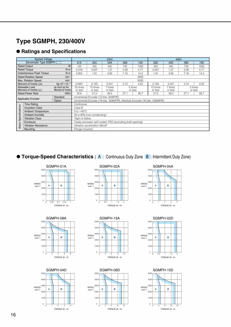
Type SGMPH, 230/400V
: Ratings and Specifications
Servomotor Type SGMPH- Applied Voltage
Rated Output
Moment of Inertia (JM)
Rated Rotation Speed
Rated Power Rate
Applicable Encoder
Max. Rotation Speed
Rated TorqueInstantaneous Peak Torque
Allowable LoadMoment of Inertia (JL)
Time RatingInsulation ClassAmbient TemperatureAmbient HumidityVibration ClassEnclosureVibration ResistanceMounting
StandardOption
N •m
kg •m2104
as much as theMoment of Inertia
N •mW
min–1
min–1
kW/s
01A100
0.3180.955
0.0491
20.6
30005000
25 timesor less
02A200
0.6371.91
0.193
21.0
15 timesor less
04A230V
4001.273.82
0.331
49.0
7 timesor less
15 timesor less
7 timesor less
08A7502.397.16
2.10
27.1
5 timesor less
5 timesor less
15A15004.7714.3
02D200
0.6371.91
04D400V
4001.273.82
08D7502.397.16
15D15004.7714.3
4.02 0.193 0.331 2.10 4.02
56.7 21.0 49.0 27.1 56.7Incremental Encoder (13 bits: 2048P/R)Incremental Encoder (16 bits: 16384P/R), Absolute Encoder (16 bits: 16384P/R)ContinuousClass B0 to 40°C20 to 80% (non-condensing)15µm or belowTotally-enclosed, self-cooled, IP55 (excluding shaft opening)Vibration acceleration 49m/s2
Flange-mountedBa
sic
Sp
eci
fica
tion
s
: Torque-Speed Characteristics ( A : Continuous Duty Zone B : Intermittent Duty Zone)
SGMPH-01A SGMPH-02A SGMPH-04A
SGMPH-08A SGMPH-15A
4000
3000
2000
1000
00 0.25 0.5 0.75 1
5000
SPEED(min–1)
TORQUE (N · m)
A B
4000
3000
2000
1000
00 2 4 6 8
5000
SPEED(min–1)
TORQUE (N · m)
A B
4000
3000
2000
1000
00 4 8 12 16
5000
SPEED(min–1)
TORQUE (N · m)
A B
4000
3000
2000
1000
00 0.5 1 1.5 2
5000
SPEED(min–1)
TORQUE (N · m)
A B
SGMPH-02D
4000
3000
2000
1000
00 0.5 1 1.5 2
5000
SPEED(min–1)
TORQUE (N · m)
A B
SGMPH-04D SGMPH-08D
4000
3000
2000
1000
00 1 2 3 4
5000
SPEED(min–1)
TORQUE (N · m)
A B
4000
3000
2000
1000
00 2 4 6 8
5000
SPEED(min–1)
TORQUE (N · m)
A B
SGMPH-15D
4000
3000
2000
1000
00 4 8 12 16
5000
SPEED(min–1)
TORQUE (N · m)
A B
16
4000
3000
2000
1000
00 1 2 3 4
5000
SPEED(min–1)
TORQUE (N · m)
A B
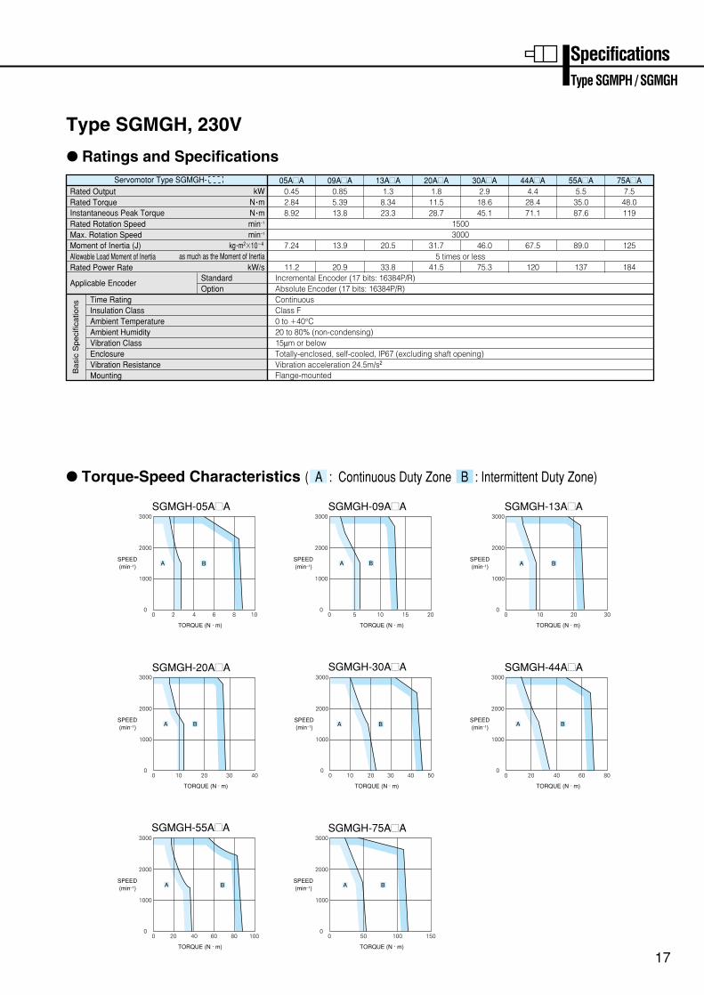
Type SGMGH, 230V
: Ratings and Specifications
: Torque-Speed Characteristics ( A : Continuous Duty Zone B : Intermittent Duty Zone)
Servomotor Type SGMGH- Rated Output
Moment of Inertia (J)
Rated Rotation Speed
Rated Power Rate
Applicable Encoder
Max. Rotation Speed
Rated TorqueInstantaneous Peak Torque
Allowable Load Moment of Inertia
Time RatingInsulation ClassAmbient TemperatureAmbient HumidityVibration ClassEnclosureVibration ResistanceMounting
StandardOption
N •m
kg •m2104
as much as the Moment of Inertia
N •mkW
min–1
min–1
kW/s
05A=A0.452.848.92
11.2
7.24
09A=A0.855.3913.8
20.9
13.9
13A=A1.3
8.3423.3
33.8
20.5
30A=A2.918.645.1
75.3
46.0
44A=A4.4
28.471.1
120
67.5
55A=A5.5
35.087.6
137
89.0
75A=A7.548.0119
184
125
20A=A1.8
11.528.7
41.5
31.7
15003000
5 times or less
Incremental Encoder (17 bits: 16384P/R)Absolute Encoder (17 bits: 16384P/R)ContinuousClass F0 to 40°C20 to 80% (non-condensing)15µm or belowTotally-enclosed, self-cooled, IP67 (excluding shaft opening)Vibration acceleration 24.5m/s2 Flange-mountedB
asi
c S
pe
cific
atio
ns
SGMGH-05A=A SGMGH-13A=ASGMGH-09A=A
SGMGH-20A=A SGMGH-30A=A
3000
2000
1000
00 2 4 6 8 10
SPEED(min–1)
TORQUE (N · m)
3000
2000
1000
3000
2000
1000
A B
00 10 20 30
SPEED(min–1)
TORQUE (N · m)
A B
00 5 10 15 20
SPEED(min–1)
TORQUE (N · m)
A B
3000
2000
1000
00 10 20 30 40
SPEED(min–1)
TORQUE (N · m)
A B
3000
2000
1000
00 10 20 30 40 50
SPEED(min–1)
TORQUE (N · m)
A B
SGMGH-55A=A3000
2000
1000
00 20 40 60 80 100
SPEED(min–1)
TORQUE (N · m)
A B
SGMGH-44A=A3000
2000
1000
00 20 40 60 80
SPEED(min–1)
TORQUE (N · m)
A B
SGMGH-75A=A3000
2000
1000
00 50 100 150
SPEED(min–1)
TORQUE (N · m)
A B
SpecificationsType SGMPH / SGMGH
17
Servomotor Type SGMGH- Rated Output
Moment of Inertia (J)
Rated Rotation Speed
Rated Power Rate
Applicable Encoder
Max. Rotation Speed
Rated TorqueInstantaneous Peak Torque
Allowable Load Moment of Inertia
Time RatingInsulation ClassAmbient TemperatureAmbient HumidityVibration ClassEnclosureVibration ResistanceMounting
StandardOption
N •m
kg •m2104
as much as the Moment of Inertia
N •mkW
min–1
min–1
kW/sIncremental Encoder (17 bits: 16384P/R)Absolute Encoder (17 bits: 16384P/R)ContinuousClass F0 to 40°C20 to 80% (non-condensing)15µm or belowTotally-enclosed, self-cooled, IP67 (excluding shaft opening)Vibration acceleration 24.5m/s2 Flange-mountedB
asi
c S
pe
cific
atio
ns
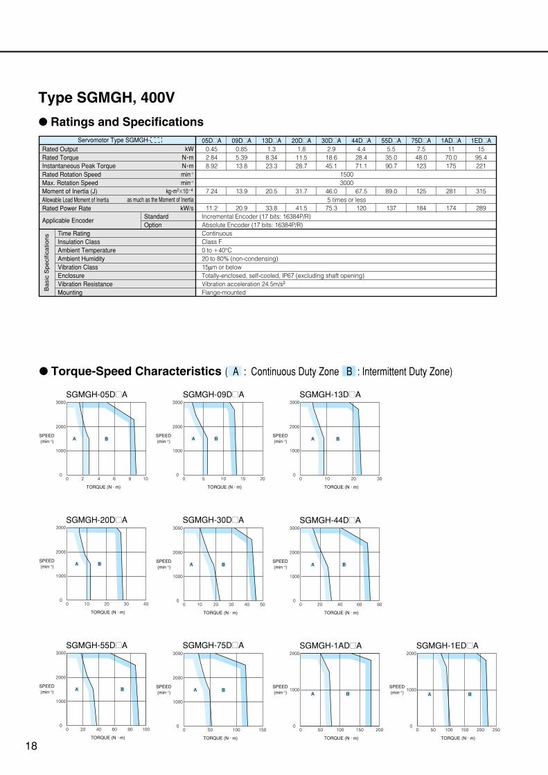
: Torque-Speed Characteristics ( A : Continuous Duty Zone B : Intermittent Duty Zone)
05D=A0.452.848.92
11.2
7.24
09D=A0.855.3913.8
20.9
13.9
13D=A1.3
8.3423.3
33.8
20.5
20D=A1.8
11.528.7
41.5
31.7
30D=A2.9
18.645.1
75.3
46.0
44D=A4.4
28.471.1
120
67.5
55D=A5.5
35.090.7
137
89.0
75D=A7.5
48.0123
184
125
1AD=A11
70.0175
174
281
1ED=A15
95.4221
289
315
SGMGH-20D=A3000
2000
1000
00 10 20 30 40
SPEED(min–1)
TORQUE (N · m)
A B
SGMGH-05D=A3000
2000
1000
00 2 4 6 8 10
SPEED(min–1)
TORQUE (N · m)
A B
SGMGH-30D=A3000
2000
1000
00 10 20 30 40 50
SPEED(min–1)
TORQUE (N · m)
A B
SGMGH-09D=A3000
2000
1000
00 5 10 15 20
SPEED(min–1)
TORQUE (N · m)
A B
SGMGH-13D=A3000
2000
1000
00 10 20 30
SPEED(min–1)
TORQUE (N · m)
A B
SGMGH-44D=A3000
2000
1000
00 20 40 60 80
SPEED(min–1)
TORQUE (N · m)
A B
SGMGH-55D=A3000
2000
1000
00 20 40 60 80 100
SPEED(min–1)
TORQUE (N · m)
A B
SGMGH-75D=A3000
2000
1000
00 50 100 150
SPEED(min–1)
TORQUE (N · m)
A BA B
SGMGH-1AD=A2000
1000
00 10050 150 200
SPEED(min–1)
TORQUE (N · m)
A B
SGMGH-1ED=A2000
1000
00 15010050 200 250
SPEED(min–1)
TORQUE (N · m)
18
15003000
5 times or less
Type SGMGH, 400V
: Ratings and Specifications
19
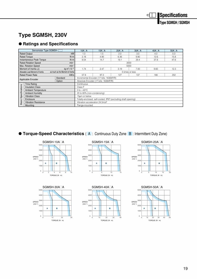
Type SGMSH, 230V
: Ratings and Specifications
: Torque-Speed Characteristics ( A : Continuous Duty Zone B : Intermittent Duty Zone)
Servomotor Type SGMSH- Rated Output
Moment of Inertia (J)
Rated Rotation Speed
Rated Power Rate
Applicable Encoder
Max. Rotation Speed
Rated TorqueInstantaneous Peak Torque
Allowable Load Moment of Inertia
Time RatingInsulation ClassAmbient TemperatureAmbient HumidityVibration ClassEnclosureVibration ResistanceMounting
StandardOption
N •m
kg •m2104
as much as the Moment of Inertia
N •mkW
min–1
min–1
kW/s
10A=A1.03.189.54
57.9
1.74
15A=A1.5
4.9014.7
97.2
2.47
20A=A2.06.3619.1
127
3.19
30A=A3.0
9.8029.4
137
7.00
40A=A4.012.637.8
166
9.60
50A=A5.015.847.6
202
12.3
30005000
5 times or less
Incremental Encoder (17 bits: 16384P/R)Absolute Encoder (17 bits: 16384P/R)ContinuousClass F0 to 40°C20 to 80% (non-condensing)15µm or belowTotally-enclosed, self-cooled, IP67 (excluding shaft opening)Vibration acceleration 24.5m/s2
Flange-mounted
SGMSH-10A=A SGMSH-15A=A SGMSH-20A=A
SGMSH-30A=A
4000
3000
2000
1000
00 2 4 6 8 10
5000
SPEED(min–1)
TORQUE (N · m)
A B
4000
3000
2000
1000
00 5 10 15
5000
SPEED(min–1)
TORQUE (N · m)
A B
4000
3000
2000
1000
00 5 10 15 20
5000
SPEED(min–1)
TORQUE (N · m)
A B
4000
3000
2000
1000
00 10 20 30
5000
SPEED(min–1)
TORQUE (N · m)
A B
Ba
sic
Sp
eci
fica
tion
s
SGMSH-50A=A
4000
3000
2000
1000
00 10 20 30 40 50
5000
SPEED(min–1)
TORQUE (N · m)
A B
SGMSH-40A=A
4000
3000
2000
1000
00 10 20 30 40
5000
SPEED(min–1)
TORQUE (N · m)
A B
SpecificationsType SGMGH / SGMSH
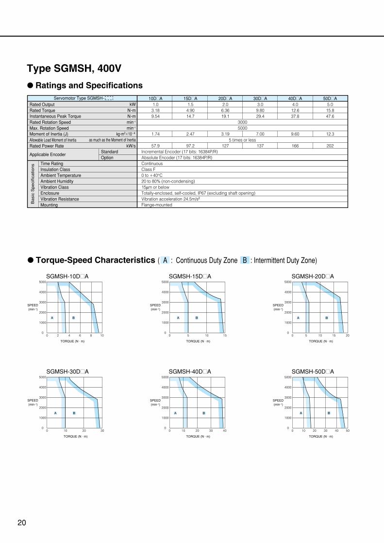
: Ratings and Specifications
: Torque-Speed Characteristics ( A : Continuous Duty Zone B : Intermittent Duty Zone)
SGMSH-15D=A
4000
3000
2000
1000
00 5 10 15
5000
SPEED(min–1)
TORQUE (N · m)
A B
SGMSH-30D=A
4000
3000
2000
1000
00 10 20 30
5000
SPEED(min–1)
TORQUE (N · m)
A B
SGMSH-10D=A
4000
3000
2000
1000
00 2 4 6 8 10
5000
SPEED(min–1)
TORQUE (N · m)
A B
SGMSH-20D=A
4000
3000
2000
1000
00 5 10 15 20
5000
SPEED(min–1)
TORQUE (N · m)
A B
SGMSH-50D=A
4000
3000
2000
1000
00 10 403020 50
5000
SPEED(min–1)
TORQUE (N · m)
A B
SGMSH-40D=A
4000
3000
2000
1000
00 10 20 30 40
5000
SPEED(min–1)
TORQUE (N · m)
A B
Servomotor Type SGMSH- Rated Output
Moment of Inertia (J)
Rated Rotation Speed
Rated Power Rate
Applicable Encoder
Max. Rotation Speed
Rated TorqueInstantaneous Peak Torque
Allowable Load Moment of Inertia
Time RatingInsulation ClassAmbient TemperatureAmbient HumidityVibration ClassEnclosureVibration ResistanceMounting
StandardOption
N •m
kg •m2104
as much as the Moment of Inertia
N •mkW
min–1
min–1
kW/s
10D=A1.03.189.54
57.9
1.74
15D=A1.5
4.9014.7
97.2
2.47
20D=A2.0
6.3619.1
127
3.19
30D=A3.0
9.8029.4
137
7.00
40D=A4.0
12.637.8
166
9.60
50D=A5.0
15.847.6
202
12.3
30005000
5 times or less
Incremental Encoder (17 bits: 16384P/R)Absolute Encoder (17 bits: 16384P/R)ContinuousClass F0 to 40°C20 to 80% (non-condensing)15µm or belowTotally-enclosed, self-cooled, IP67 (excluding shaft opening)Vibration acceleration 24.5m/s2 Flange-mountedB
asi
c S
pe
cific
atio
ns
20
Type SGMSH, 400V
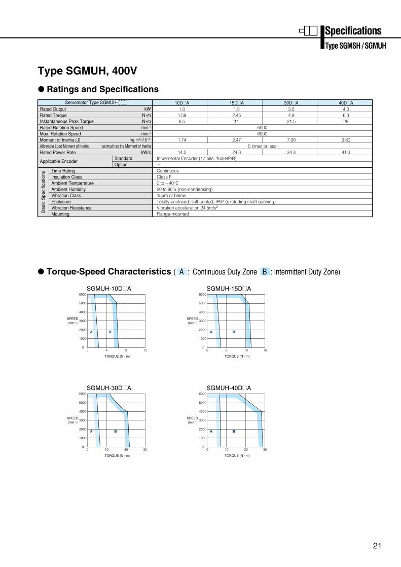
Servomotor Type SGMUH- Rated Output
Moment of Inertia (J)
Rated Rotation Speed
Rated Power Rate
Applicable Encoder
Max. Rotation Speed
Rated TorqueInstantaneous Peak Torque
Allowable Load Moment of Inertia
Time RatingInsulation ClassAmbient TemperatureAmbient HumidityVibration ClassEnclosureVibration ResistanceMounting
StandardOption
N •m
kg •m2104
as much as the Moment of Inertia
N •mkW
min–1
min–1
kW/s
60006000
5 times or less
Incremental Encoder (17 bits: 16384P/R)–ContinuousClass F0 to 40°C20 to 80% (non-condensing)15µm or belowTotally-enclosed, self-cooled, IP67 (excluding shaft opening)Vibration acceleration 24.5m/s2 Flange-mountedB
asi
c S
pe
cific
atio
ns
: Ratings and Specifications
: Torque-Speed Characteristics ( A : Continuous Duty Zone B : Intermittent Duty Zone)
SpecificationsType SGMSH / SGMUH
10D=A1.01.596.5
14.5
1.74
15D=A1.5
2.4511
24.3
2.47
30D=A3.04.9
21.5
34.3
7.00
40D=A4.06.329
41.3
9.60
21
SGMUH-10D=A
4000
3000
2000
1000
00 4 8 12
5000
6000
SPEED(min–1)
TORQUE (N · m)
A B
SGMUH-30D=A
4000
3000
2000
1000
00 10 20 30
5000
6000
SPEED(min–1)
TORQUE (N · m)
A B
SGMUH-15D=A
4000
3000
2000
1000
00 5 10 15
5000
6000
SPEED(min–1)
TORQUE (N · m)
A B
SGMUH-40D=A
4000
3000
2000
1000
00 10 20 30
5000
6000
SPEED(min–1)
TORQUE (N · m)
A B
Type SGMUH, 400V

22
SERVOPACK Specifications
Characteristics
:Single-phase, 230V
Ba
sic
Sp
eci
fica
tion
s
Co
nd
itio
ns
SERVOPACK Type
Applicable Servomotor
SGMAH-
SGMPH-
Input Power Supply
Main Circuit
Control Circuit
Control Method
Feedback
Usage/storage Temperature
Usage/storage Humidity
Altitude
Vibration/Shock Resistance
Configuration
Approx. Mass kg
A3AE
A3A
–
A5AE
A5A
–
01AE
01A
01A
02AE
02A
02A
04AE
04A
04A
08AE-S
08A
08A
220 to 230VAC10 to 15% (50/60Hz)
15AE-S
–
15A
For single-phase, 200 to 230VAC 10 to 15% (50/60Hz)
For single-phase, 200 to 230VAC 10 to 15% (50/60Hz)
Single-phase full-wave rectification / IGBT / PWM / sine-wave current drive method
Serial encoder (incremental/absolute value)
0 to 55°C/ -20 to 85°C
90%RH or less (non-condensing)
1000m or less above sea level
4.9m/s2 /19.6m/s2
Base mounted (Rack mount is also available)
0.8 1.1 1.7 3.8
:Three-phase, 230V
Ba
sic
Sp
eci
fica
tion
s
Co
nd
itio
ns
SERVOPACK Type
Applicable Servomotor
SGMGH-
SGMSH-
Input Power Supply
Main Circuit
Control Circuit
Control Method
Feedback
Usage/storage Temperature
Usage/storage Humidity
Altitude
Vibration/Shock Resistance
Configuration
Approx. Mass kg
05AE
05A=A
–
10AE
09A=A
10A=A
15AE
13A=A
15A=A
20AE
20A=A
20A=A
30AE
30A=A
30A=A
50AE
44A=A
40A=A 50A=A
60AE
55A=A
–
75AE
75A=A
–
For three-phase, 200 to 230VAC 10 to 15% (50/60Hz)
For three-phase, 200 to 230VAC 10 to 15% (50/60Hz)
Single-phase full-wave rectification / IGBT / PWM / sine-wave current drive method
Serial encoder (incremental/absolute value)
0 to 55°C/ -20 to 85°C
90%RH or less (non-condensing)
1000m or less above sea level
4.9m/s2 /19.6m/s2
Base mounted (Rack mount is also available)
1.7 3.82.8 5.5 15
:Three-phase, 400V
Ba
sic
Sp
eci
fica
tion
s
Co
nd
itio
ns
SERVOPACK Type
Applicable Servomotor
SGMGH-
SGMUH-
Input Power Supply
Main Circuit
Control Circuit
Control Method
Feedback
Usage/storage Temperature
Usage/storage Humidity
Altitude
Vibration/Shock Resistance
Configuration
Approx. Mass kg
SGMSH-
05DE
05D=A
–
–
10DE
09D=A
10D=A
10D=A
15DE
13D=A
15D=A
15D=A
20DE
20D=A
–
20D=A
30DE
30D=A
30D=A
30D=A
50DE
44D=A
40D=A
40D=A 50D=A
60DE
55D=A
–
–
75DE
75D=A
–
–
1ADE
1AD=A
–
–
1EDE
1ED=A
–
–
For three-phase, 380 to 480VAC 10 to 15% (50/60Hz)
24VDC 15%
Three-phase full-wave rectification / IGBT / PWM / sine-wave current drive method
Serial encoder (incremental/absolute value)
0 to 55°C/ -20 to 85°C
90%RH or less (non-condensing)
1000m or less above sea level
4.9m/s2 /19.6m/s2
Base mounted (Rack mount is also available)
3.8 5.5 15 222.8
SGDH-
SGDH-
SGDH-
23
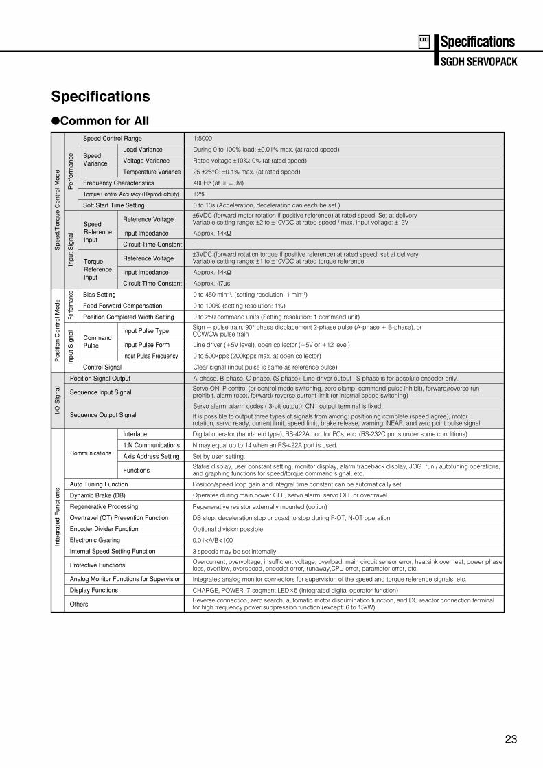
Specifications
:Common for All
SpecificationsSGDH SERVOPACK
Sp
ee
d/T
orq
ue
Co
ntr
ol M
od
eP
osi
tion
Co
ntr
ol M
od
eI/
O S
ign
al
Inte
gra
ted
Fu
nct
ion
s
Pe
rfo
rma
nce
Inp
ut
Sig
na
lPe
rform
ance
Inp
ut
Sig
na
l
Speed Control Range
Load Variance
Voltage Variance
Temperature Variance
Frequency Characteristics
Torque Control Accuracy (Reproducibility)
Soft Start Time Setting
Reference Voltage
Input Impedance
Circuit Time Constant
Reference Voltage
Input Impedance
Circuit Time Constant
Bias Setting
Feed Forward Compensation
Position Completed Width Setting
Input Pulse Type
Input Pulse Form
Input Pulse Frequency
Control Signal
Position Signal Output
Sequence Input Signal
Sequence Output Signal
Interface
1:N Communications
Axis Address Setting
Functions
Auto Tuning Function
Dynamic Brake (DB)
Regenerative Processing
Overtravel (OT) Prevention Function
Encoder Divider Function
Electronic Gearing
Internal Speed Setting Function
Protective Functions
Analog Monitor Functions for Supervision
Display Functions
Others
Speed Variance
SpeedReferenceInput
TorqueReferenceInput
Command Pulse
Communications
1:5000
During 0 to 100% load: ±0.01% max. (at rated speed)
Rated voltage ±10%: 0% (at rated speed)
25 ±25°C: ±0.1% max. (at rated speed)
400Hz (at JL = JM)
±2%
0 to 10s (Acceleration, deceleration can each be set.)
Approx. 14kΩ
Approx. 14kΩ
Approx. 47µs
0 to 450 min–1. (setting resolution: 1 min–1)
0 to 100% (setting resolution: 1%)
0 to 250 command units (Setting resolution: 1 command unit)
Line driver (5V level), open collector (5V or 12 level)
0 to 500kpps (200kpps max. at open collector)
Clear signal (input pulse is same as reference pulse)
A-phase, B-phase, C-phase, (S-phase): Line driver output S-phase is for absolute encoder only.
Servo alarm, alarm codes ( 3-bit output): CN1 output terminal is fixed.
–
±6VDC (forward motor rotation if positive reference) at rated speed: Set at delivery Variable setting range: ±2 to ±10VDC at rated speed / max. input voltage: ±12V
±3VDC (forward rotation torque if positive reference) at rated speed: set at delivery Variable setting range: ±1 to ±10VDC at rated torque reference
Sign pulse train, 90° phase displacement 2-phase pulse (A-phase B-phase), or CCW/CW pulse train
Servo ON, P control (or control mode switching, zero clamp, command pulse inhibit), forward/reverse run prohibit, alarm reset, forward/ reverse current limit (or internal speed switching)
Status display, user constant setting, monitor display, alarm traceback display, JOG run / autotuning operations, and graphing functions for speed/torque command signal, etc.
Overcurrent, overvoltage, insufficient voltage, overload, main circuit sensor error, heatsink overheat, power phaseloss, overflow, overspeed, encoder error, runaway,CPU error, parameter error, etc.
Reverse connection, zero search, automatic motor discrimination function, and DC reactor connection terminalfor high frequency power suppression function (except: 6 to 15kW)
It is possible to output three types of signals from among: positioning complete (speed agree), motor rotation, servo ready, current limit, speed limit, brake release, warning, NEAR, and zero point pulse signal
N may equal up to 14 when an RS-422A port is used.
Digital operator (hand-held type), RS-422A port for PCs, etc. (RS-232C ports under some conditions)
Set by user setting.
Operates during main power OFF, servo alarm, servo OFF or overtravel
Position/speed loop gain and integral time constant can be automatically set.
Regenerative resistor externally mounted (option)
DB stop, deceleration stop or coast to stop during P-OT, N-OT operation
Optional division possible
0.01<A/B<100
3 speeds may be set internally
Integrates analog monitor connectors for supervision of the speed and torque reference signals, etc.
CHARGE, POWER, 7-segment LED5 (Integrated digital operator function)
4-LZ DIA.MOUNTING HOLES
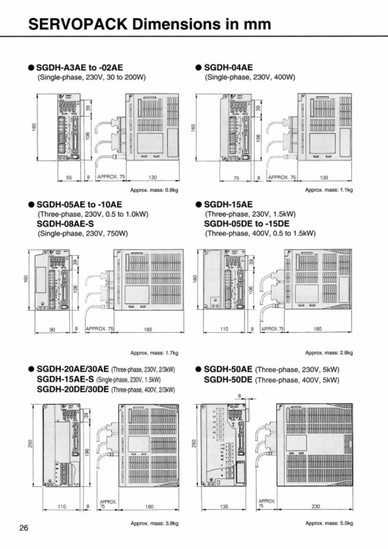
24
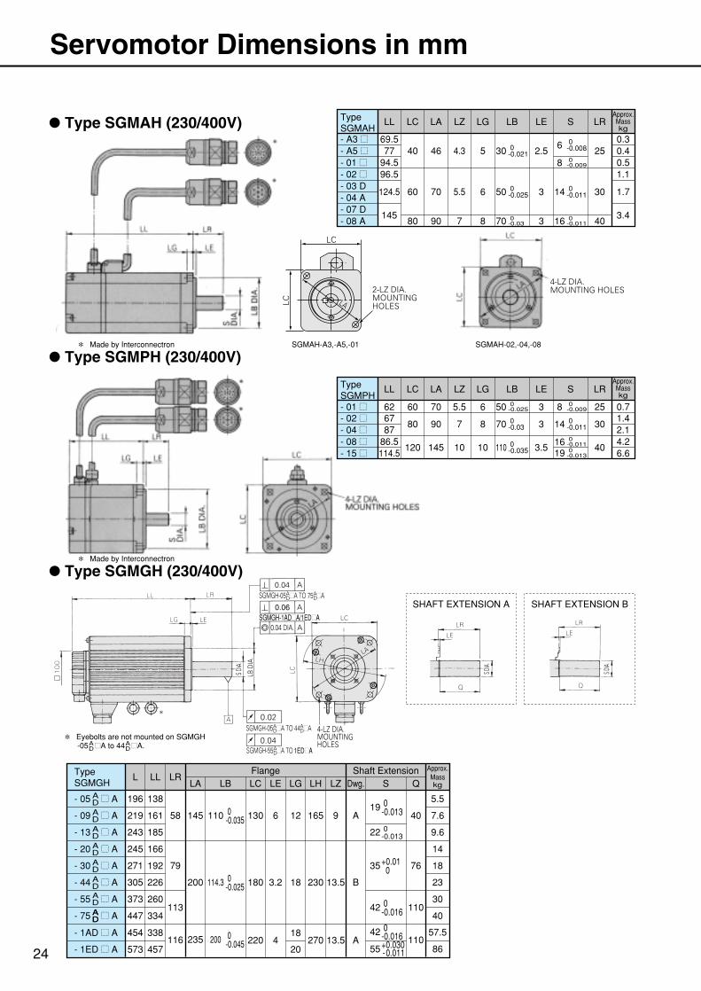
Servomotor Dimensions in mm
: Type SGMAH (230/400V)
: Type SGMPH (230/400V)
: Type SGMGH (230/400V)
TypeSGMAH
0.3- A3 =
LL LC LA LZ LG LB LE S LR
69.577
94.596.5
124.5
145
0.40.51.1
1.7
3.4
40
60
80
46
70
90
5
6
8
2.5
3
3
25
30
40
4.3
5.5
7
- A5 =- 01 =- 02 =- 03 D
- 07 D- 04 A
- 08 A
TypeSGMPH
TypeSGMGH
Approx.Masskg
Approx.Masskg
Approx.Masskg
L LLFlange Shaft Extension
LRLA
0-0.03
1.4- 02 =- 01 =
- 05 = A 196
219
243
245
271
305
373
447
138
161
185
166
192
226
260
58
200
235
145
LB
114.3
110
LC LE LG LH LZ
180
130
3.2
6
18
12
230
165
13.5
220 418
20270 13.5
9
Dwg.
B
A
A
S Q
76
110
110
40
79
113
116
334
5.5
7.6
9.6
14
18
23
30
40
57.5
86
LL LC LA LZ LG LB LE S LR
6787
86.5114.5
2.14.26.6
80
120
90
145
8
10
70
0-0.035110
3
3.5
30
40
7
10
- 04 =- 08 =- 15 =
62 0.760 70 6 0-0.02550
0-0.01114
0-0.0098
0-0.02550
0-0.02130
0-0.0370
0-0.0086
0-0.01114
0-0.01116
0-0.0098
0-0.01116 0-0.01319
3 255.5
AD
- 09 = AAD
- 13 = AAD
- 20 = AAD
- 30 = AADADADADAD
- 44 = A
0-0.035
19 0-0.013
22 0-0.013
35+0.01 0
42 0-0.016
42 0-0.016
55+0.030 - 0.011
0-0.025
200 0-0.045
- 55 = A
- 75 = A
454
573
338
457
- 1AD = A
- 1ED = A
SHAFT EXTENSION A SHAFT EXTENSION B
AD
AD
* Eyebolts are not mounted on SGMGH -05 =A to 44 =A.
* Made by Interconnectron
* Made by Interconnectron SGMAH-A3,-A5,-01 SGMAH-02,-04,-08
2-LZ DIA.MOUNTING HOLES
LC
LC LA
0.06SGMGH-1AD A/1ED A
1ED A
25
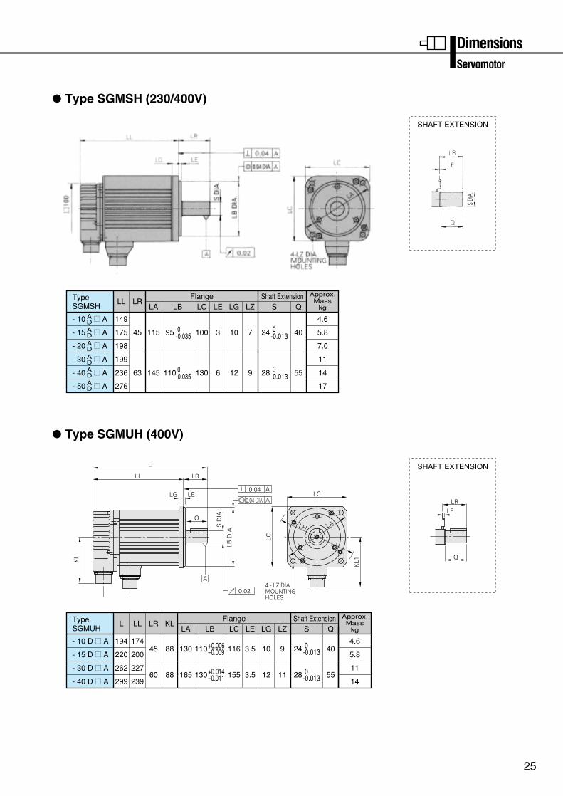
: Type SGMSH (230/400V)
Dimensions
TypeSGMSH
Approx.Mass
kgLL
Flange Shaft ExtensionLR
LA
- 10 = A 149
175
198
199
236
276
45
145
115
LB
110
95
LC LE LG LZ
130
100
6
3
12
10
9
7
S Q
55
40
63
4.6
5.8
7.0
11
14
17
AD
- 15 = AAD
- 20 = AAD
- 30 = AADADAD
- 40 = A
- 50 = A
0-0.035 24 0
-0.013
28 0-0.013
0-0.035
: Type SGMUH (400V)
TypeSGMUH
Approx.Mass
kgLL
Flange Shaft ExtensionLA
- 10 D = A 174
200
227
LR
45
KL
88 130 116 3.5 10 9
LB
110
LC LE LG LZ S Q
404.6
5.8- 15 D = A
- 30 D = A
+0.006–0.009 24 0
-0.013
239
L
194
220
262
29960 88 165 155 3.5 12 11 55
14
11
- 40 D = A130+0.014
–0.011 28 0-0.013
SHAFT EXTENSION
Servomotor
SHAFT EXTENSION
Q
LE
L
LL LR
LG
KL
A
LC
KL1
LC
LH LAS D
IA.
LB D
IA.
0.04 A
0.04 DIA.
4 - LZ DIA.MOUNTINGHOLES
A
0.02
LRLE
Q
27
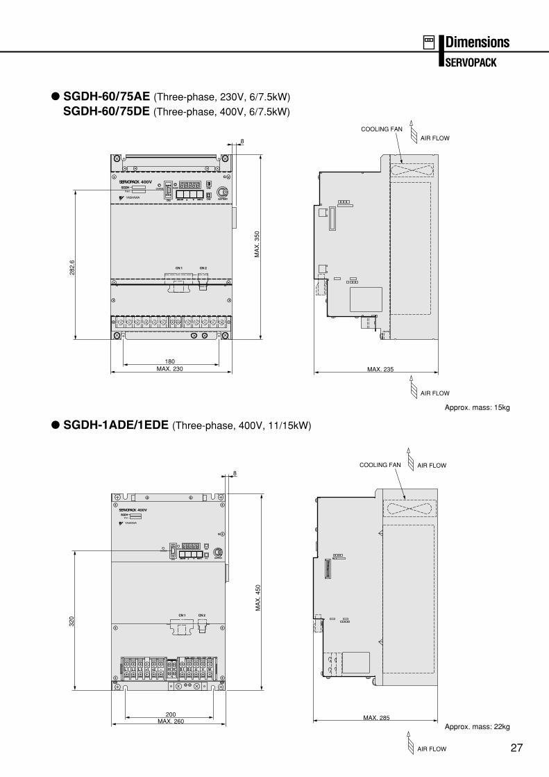
: SGDH-60/75AE (Three-phase, 230V, 6/7.5kW)
SGDH-60/75DE (Three-phase, 400V, 6/7.5kW)
DimensionsSERVOPACK
Approx. mass: 15kg
Approx. mass: 22kg
: SGDH-1ADE/1EDE (Three-phase, 400V, 11/15kW)
SGDHV e r .
YASKAWA
POWER
CN3
CN8
G
BATTERYCN5
CHARGE
CN 1 CN 2
8
MA
X. 3
50
282.
6
180MAX. 230
COOLING FAN
AIR FLOW
MAX. 235
AIR FLOW
SGDHV e r .
YASKAWA
POWER CN 8
G
CN3
CHARGE
CN 5 BATTERY
L 1 L 2 B 124V 0V B 2 U V WL 3 +1 +2 -
8
CN 1 CN 2
MA
X. 4
50
320
200MAX. 260
COOLING FAN AIR FLOW
AIR FLOW
MAX. 285
28
Function Description
For High Performance
Model follow-up control Vibration suppression control
The observer reduces the vibration, and high servo gain drive is achieved when a machine drive system is subject to vibrations. This function enhances the servo characteristics.
New
New
A mechanical system is modeled to compensatefor system delay and suppress vibrations whena machine has a low characteristic frequency.This function reduces the settling time of rigid machinery.
Mechanical resonance suppression filter Torque reference filterNew
Resonance is suppressed by setting the vibrationsuppression filter in accordance with mechanicalsystem resonance frequency when a high frequency resonance noise is made by themachine.
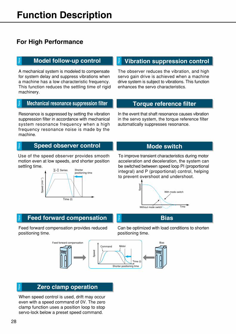
Use of the speed observer provides smooth motion even at low speeds, and shorter position settling time.
Spe
ed (
min
–1)
Time (t)
Series Shorter positioning time
Mode switch
To improve transient characteristics during motoracceleration and deceleration, the system can be switched between speed loop PI (proportionalintegral) and P (proportional) control, helping to prevent overshoot and undershoot.
Spe
ed
Without mode switch
With mode switch
Time
Feed forward compensation Bias
Feed forward compensation provides reduced positioning time.
Can be optimized with load conditions to shortenpositioning time.
Command Motor
Shorter positioning time
Feed forward compensation Bias
Spe
ed
Time (t)
New
New
Zero clamp operation
When speed control is used, drift may occur even with a speed command of 0V. The zero clamp function uses a position loop to stop servo-lock below a preset speed command.
New
In the event that shaft resonance causes vibration in the servo system, the torque reference filter automatically suppresses resonance.
Speed observer controlNew
29
For Easy Setup
Functions
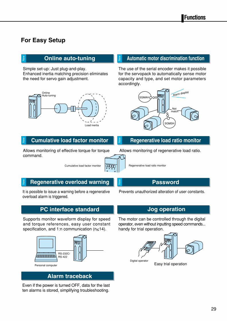
Online auto-tuning Automatic motor discrimination function
Simple set-up: Just plug-and-play. Enhanced inertia matching precision eliminatesthe need for servo gain adjustment.
The use of the serial encoder makes it possible for the servopack to automatically sense motor capacity and type, and set motor parameters accordingly.
Load inertia
OnlineAuto-tuning
SGMSH
SGMAH
Not match
Alarm display
New
New
Cumulative load factor monitor Regenerative load ratio monitor
Allows monitoring of effective torque for torque command.
Allows monitoring of regenerative load ratio.
Cumulative load factor monitor Regenerative load ratio monitor
New
New
Regenerative overload warning
It is possible to issue a warning before a regenerative overload alarm is triggered.
New
Password
Prevents unauthorized alteration of user constants.
New
PC interface standard Jog operation
The motor can be controlled through the digital operator, even without inputting speed commands... handy for trial operation.
RS-232C/RS-422
Personal computer Easy trial operationDigital operator
Supports monitor waveform display for speed and torque references, easy user constant specification, and 1:n communication (n<14).
Alarm traceback
Even if the power is turned OFF, data for the lastten alarms is stored, simplifying troubleshooting.
30
For Flexible Adjustment
New
New
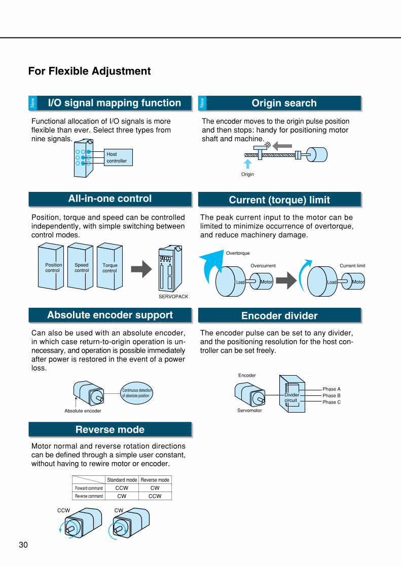
I/O signal mapping function
Functional allocation of I/O signals is more flexible than ever. Select three types fromnine signals.
Host controller
Origin search
The encoder moves to the origin pulse position and then stops: handy for positioning motor shaft and machine.
Origin
All-in-one control
Position, torque and speed can be controlledindependently, with simple switching between control modes.
SERVOPACK
Position control
Speed control
Torque control
Current (torque) limit
The peak current input to the motor can belimited to minimize occurrence of overtorque,and reduce machinery damage.
Load Motor
Overcurrent Current limit
Load Motor
Overtorque
Absolute encoder support Encoder divider
Reverse mode
Can also be used with an absolute encoder, in which case return-to-origin operation is un-necessary, and operation is possible immediately after power is restored in the event of a power loss.
The encoder pulse can be set to any divider, and the positioning resolution for the host con-troller can be set freely.
Motor normal and reverse rotation directions can be defined through a simple user constant, without having to rewire motor or encoder.
Standard mode
Forward command
Reverse command
Reverse mode
CCW
CW
CW
CCW
ServomotorAbsolute encoder
Encoder
Phase A Phase BPhase C
Divider circuit
CCW CW
Continuous detectionof absolute position
31
Functions
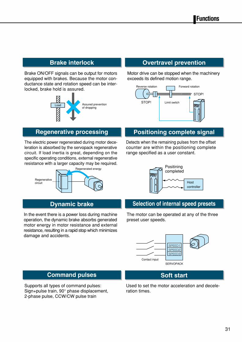
Brake interlock Overtravel prevention
Brake ON/OFF signals can be output for motors equipped with brakes. Because the motor con-ductance state and rotation speed can be inter-locked, brake hold is assured.
Motor drive can be stopped when the machinery exceeds its defined motion range.
Reverse rotation Forward rotation
Limit switchSTOP!
STOP!
Load Assured preventionof dropping
Regenerative processing
The electric power regenerated during motor dece-leration is absorbed by the servopack regenerative circuit. If load inertia is great, depending on the specific operating conditions, external regenerativeresistance with a larger capacity may be required.
Regenerated energy
Regenerativecircuit
Positioning complete signal
Detects when the remaining pulses from the offsetcounter are within the positioning complete range specified as a user constant.
Host controller
Positiningcompleted
Dynamic brake
In the event there is a power loss during machine operation, the dynamic brake absorbs generated motor energy in motor resistance and external resistance, resulting in a rapid stop which minimizes damage and accidents.
Selection of internal speed presets
The motor can be operated at any of the threepreset user speeds.
Contact input
SERVOPACK
SPEED1
SPEED2
SPEED3
Command pulses
Supports all types of command pulses:Sign+pulse train, 90° phase displacement,2-phase pulse, CCW/CW pulse train
Soft start
Used to set the motor acceleration and decele-ration times.
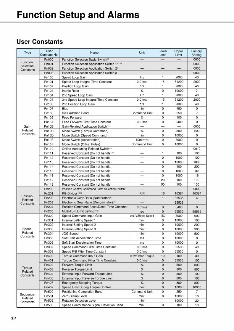
User Constants
32
Function Setup and Alarms
Pn000FunctionSelectionConstants
Gain-Related
Constants
Position-Related
Constants
Speed-Related
Constants
Torque-Related
Constants
Sequence-Related
Constants
Type Name Unit LowerLimit
UpperLimit
FactorySetting
UserConstant No.
Function Selection Basic Switch*3 — — — 000000000000000240
200040040
2000400700
0000200000
001010010010002003216
100100000016384
— — —— — —— — —Hz 1 2000
0.01ms 15 512001/s 1 2000% 0 10000Hz 1 2000
0.01ms 15 512001/s 1 2000
min–1 0 450Command Unit 0 250
% 0 1000.01ms 0 6400
— — —% 0 800
min–1 0 1000010min–1/s 0 3000
Command Unit 0 10000— — —— 1 100— 0 1000— 0 10000— 0 400— 0 1000— 0 1000— 20 100— 50 100— — —
P/R 16 16384
4— 1 65535
1— 1 65535
00.01ms 0 640065535rev 0 65535
6000.01V/Rated Speed 150 3000100min–1 0 10000200min–1 0 10000300min–1 0 10000500min–1 0 100000ms 0 100000ms 0 10000400.01ms 0 6553500.01ms 0 65535300.1V/Rated Torque 10 1001000.01ms 0 65535800% 0 800
Function Selection Application Switch 1*1*3
Function Selection Application Switch 2*3
Function Selection Application Switch 3Speed Loop GainSpeed Loop Integral Time ConstantPosition Loop GainInertia Ratio2nd Speed Loop Gain2nd Speed Loop Integral Time Constant2nd Position Loop GainBiasBias Addition BandFeed ForwardFeed Forward Filter Time ConstantGain-Related Application Switch*3
Mode Switch (Torque Command)Mode Switch (Speed Command)Mode Switch (Acceleration)Mode Switch (Offset Pulse)Online Autotuning-Related Switch*3
Pn001Pn002Pn003Pn100Pn101Pn102Pn103Pn104Pn105Pn106Pn107Pn108Pn109Pn10APn10BPn10CPn10DPn10EPn10FPn110
Reserved Constant (Do not handle)*2Pn111Reserved Constant (Do not handle)Pn112Reserved Constant (Do not handle)Pn113Reserved Constant (Do not handle)Pn114Reserved Constant (Do not handle)Pn115Reserved Constant (Do not handle)Pn116Reserved Constant (Do not handle)Pn117Reserved Constant (Do not handle)Pn118Position Control Command Form Selection Switch*3Pn200PG Divider*3*5Pn201Electronic Gear Ratio (Numerator)*3Pn202Electronic Gear Ratio (Denominator)*3Pn203Position Command Accel/Decel Time ConstantPn204Multi-Turn Limit Setting*1*3Pn205Speed Command Input GainPn300Internal Setting Speed 1Pn301Internal Setting Speed 2Pn302Internal Setting Speed 3Pn303JOG SpeedPn304Soft Start Acceleration TimePn305Soft Start Deceleration TimePn306Speed Command Filter Time ConstantPn307Speed F/B Filter Time ConstantPn308Torque Command Input GainPn400Torque Command Filter Time ConstantPn401Forward Torque LimitPn402
800% 0 800Reverse Torque LimitPn403100% 0 800External Input Forward Torque LimitPn404100% 0 800External Input Reverse Torque LimitPn405800% 0 800Emergency Stopping TorquePn406
10000min–1 0 10000Speed Limit During Torque ControlPn4077Command Unit 0 250Positioning Completion BandPn50010min–1 0 10000Zero-Clamp LevelPn50120min–1 1 10000Rotation Detection LevelPn50210min–1 0 100Speed Conformance Signal Detection BandPn503
Functions
33
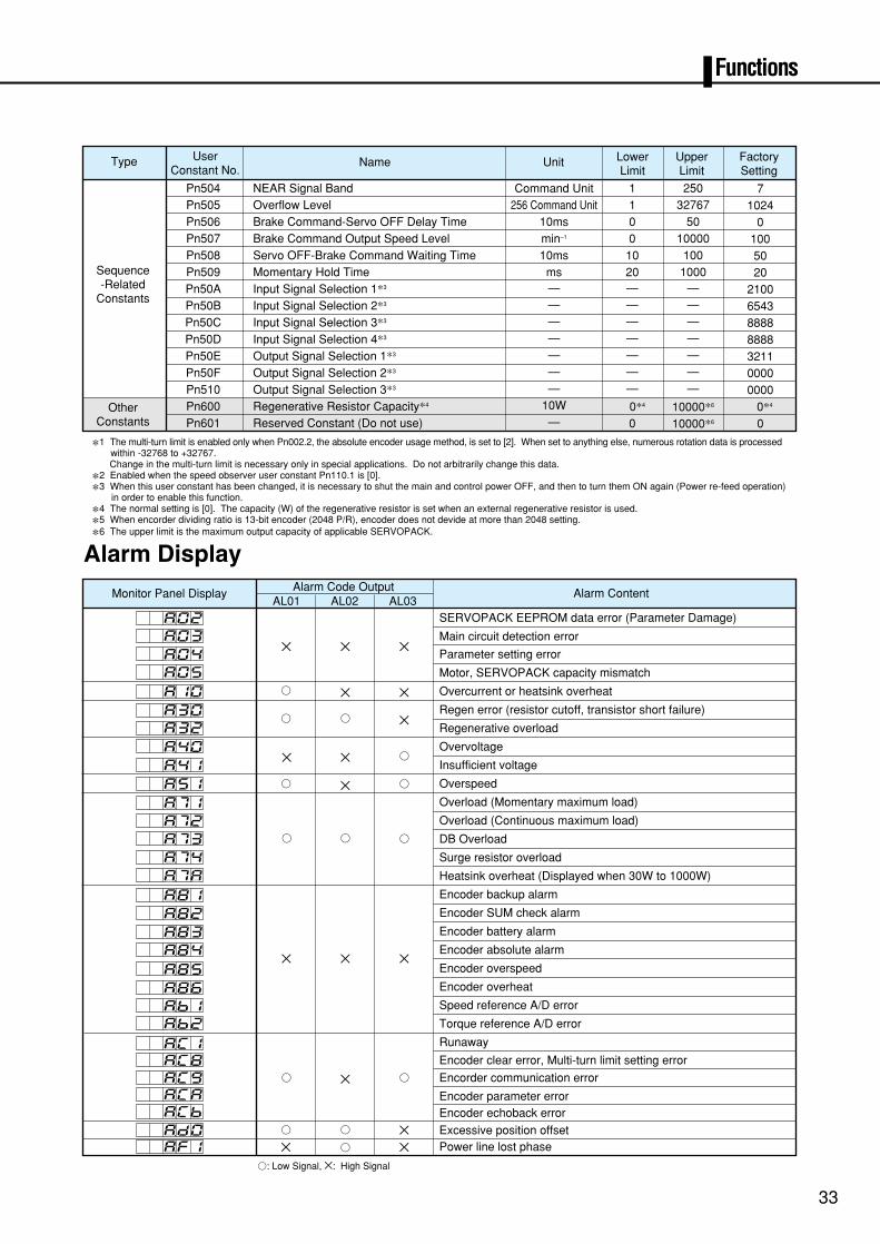
>: Low Signal, ×: High Signal
Pn504
Sequence-Related
Constants
OtherConstants
Type Name Unit LowerLimit
UpperLimit
FactorySetting
UserConstant No.
NEAR Signal Band Command Unit 1 250 71024
0100
256 Command Unit 1 3276710ms 0 50min–1 0 10000
Overflow LevelBrake Command-Servo OFF Delay TimeBrake Command Output Speed Level
Pn505Pn506
5010ms 10 100Servo OFF-Brake Command Waiting TimePn508
20ms 20 1000Momentary Hold TimePn509
2100— — —Input Signal Selection 1*3Pn50A
6543— — —Input Signal Selection 2*3Pn50B
8888— — —Input Signal Selection 3*3Pn50C
8888— — —Input Signal Selection 4*3Pn50D
3211— — —Output Signal Selection 1*3Pn50E
0000— — —Output Signal Selection 2*3Pn50F
0000— — —Output Signal Selection 3*3Pn510
0*410W 0*4 10000*6Regenerative Resistor Capacity*4Pn600
0— 0 10000*6Reserved Constant (Do not use)
Alarm Content
SERVOPACK EEPROM data error (Parameter Damage)
Main circuit detection error
Parameter setting error
Motor, SERVOPACK capacity mismatch
Overcurrent or heatsink overheat
Regen error (resistor cutoff, transistor short failure)
Regenerative overload
Overvoltage
Insufficient voltage
Overspeed
Overload (Momentary maximum load)
Overload (Continuous maximum load)
DB Overload
Surge resistor overload
Heatsink overheat (Displayed when 30W to 1000W)
Encoder backup alarm
Encoder SUM check alarm
Encoder battery alarm
Encoder absolute alarm
Encoder overspeed
Encoder overheat
Speed reference A/D error
Torque reference A/D error
Runaway
Encoder clear error, Multi-turn limit setting error
Encorder communication error
Encoder parameter errorEncoder echoback error
Excessive position offsetPower line lost phase
Pn601
Pn507
*1 The multi-turn limit is enabled only when Pn002.2, the absolute encoder usage method, is set to [2]. When set to anything else, numerous rotation data is processed within -32768 to +32767. Change in the multi-turn limit is necessary only in special applications. Do not arbitrarily change this data.
*2 Enabled when the speed observer user constant Pn110.1 is [0].
*3 When this user constant has been changed, it is necessary to shut the main and control power OFF, and then to turn them ON again (Power re-feed operation) in order to enable this function.
*4 The normal setting is [0]. The capacity (W) of the regenerative resistor is set when an external regenerative resistor is used.
*5 When encorder dividing ratio is 13-bit encoder (2048 P/R), encoder does not devide at more than 2048 setting.
*6 The upper limit is the maximum output capacity of applicable SERVOPACK.
Alarm Display
Monitor Panel Display Alarm Code OutputAL01 AL02 AL03
802803
804805
871872873
874878
881
882
883884
885
8868B18B2
8C18C88C98C88CB
8D08F1
830832
840
841
810
851
.
.
.
.
.
.
.
.
.
.
.
.
.
.
.
.
.
.
.
.
.
.
.
.
.
.
.
.
.
.
× × ×
× × ×
> × >
> × ×> > ×
> >
>
×××
× × >
> × >
> > >
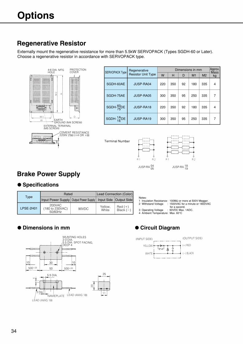
Regenerative ResistorExternally mount the regenerative resistance for more than 5.5kW SERVOPACK (Types SGDH-60 or Later).Choose a regenerative resistor in accordance with SERVOPACK type.
Brake Power Supply
34
Options
SERVOPACK TypeRegenerativeResistor Unit Type
SGDH-60AE JUSP-RA04 220 350 92 180 335 4
300 350 95 250 335 7
Dimensions in mm
W H D M1 M2
Approx.Mass
kg
SGDH-75AE JUSP-RA05
SGDH- DE JUSP-RA18 220 350 92 180 335 4
300 350 95 250 335 7SGDH- DE
6075
1A1E
JUSP-RA19
TypeRated
Input Power Supply Output Power Supply
Lead Connection (Color)
LPSE-2H01200VAC
(180 to 230VAC)50/60Hz
90VDCYellow,White
Red ()Black ()
Input Side Output Side
: Specifications
: Dimensions in mm : Circuit Diagram
Notes:1 Insulation Resistance: 100MΩ or more at 500V Megger.2 Withstand Voltage : 1500VAC for a minute or 1800VAC for a second.3 Operating Voltage : 90VDC Max. 1ADC.4 Ambient Temperature: Max. 60°C
JUSP-RA 0405 JUSP-RA 18
19
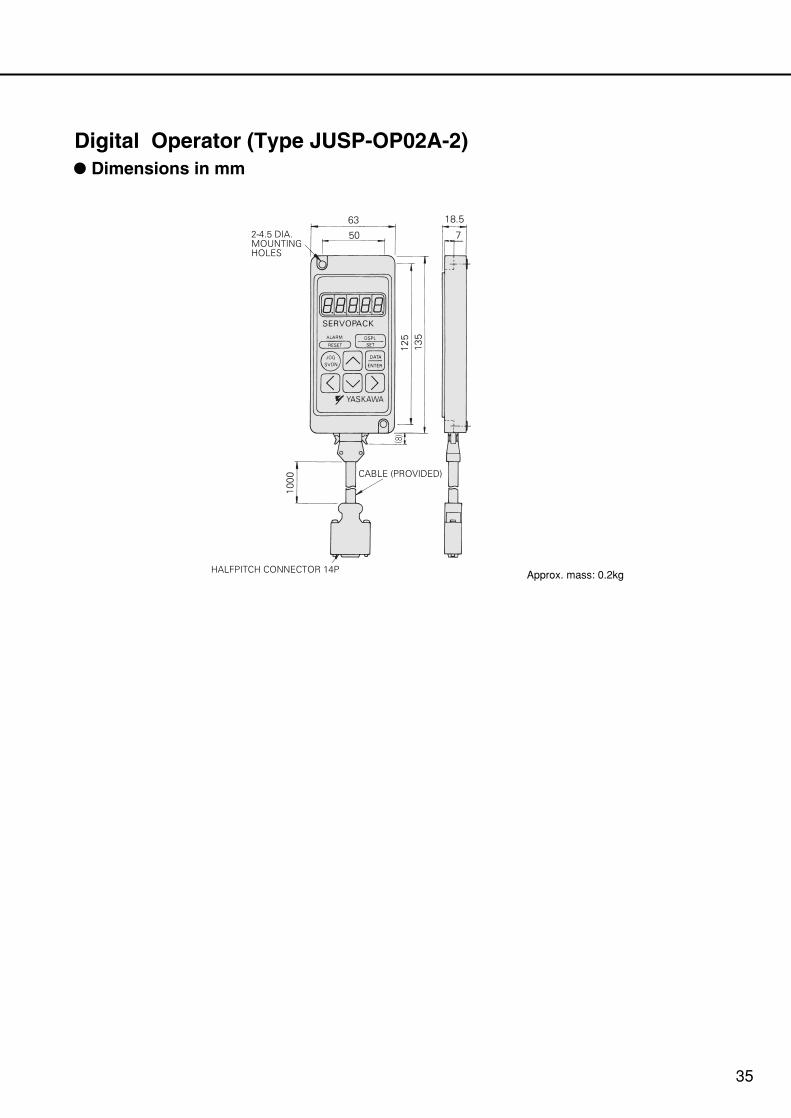
Digital Operator (Type JUSP-OP02A-2): Dimensions in mm
Approx. mass: 0.2kg
2-4.5 DIA.MOUNTING HOLES
HALFPITCH CONNECTOR 14P
CABLE (PROVIDED)
35
SERIES
LITERATURE NO. KAE-S800-32D
Printed in Japan September 2002 99-1 1.5WA
96-87139
YASKAWA
YASKAWA ELECTRIC CORPORATION
Specifications are subject to change without notice for ongoing product modifications and improvements. 02-51
7
IRUMA BUSINESS CENTER480, Kamifujisawa, Iruma, Saitama 358-8555, JapanPhone 81-42-962-5696 Fax 81-42-962-6138
YASKAWA ELECTRIC AMERICA, INC.2121 Norman Drive South, Waukegan, IL 60085, U.S.A.Phone 1-847-887-7000 Fax 1-847-887-7370
MOTOMAN INC. HEADQUARTERS805 Liberty Lane West Carrollton, OH 45449, U.S.A.Phone 1-937-847-6200 Fax 1-937-847-6277
YASKAWA ELETRICO DO BRASIL COMERCIO LTD.A.Avenida Fagundes Filho, 620 Bairro Saude-Sao Paulo-SP, Brazil CEP: 04304-000Phone 55-11-5071-2552 Fax 55-11-5581-8795
YASKAWA ELECTRIC EUROPE GmbHAm Kronberger Hang 2, 65824 Schwalbach, GermanyPhone 49-6196-569-300 Fax 49-6196-569-398
Motoman Robotics Europe ABBox 504 S38525 Torsas, SwedenPhone 46-486-48800 Fax 46-486-41410
Motoman Robotec GmbHKammerfeldstraβe 1, 85391 Allershausen, GermanyPhone 49-8166-90-100 Fax 49-8166-90-103
YASKAWA ELECTRIC UK LTD.1 Hunt Hill Orchardton Woods Cumbernauld, G68 9LF, United KingdomPhone 44-1236-735000 Fax 44-1236-458182
YASKAWA ELECTRIC KOREA CORPORATIONKfpa Bldg #1201, 35-4 Youido-dong, Yeongdungpo-Ku, Seoul 150-010, KoreaPhone 82-2-784-7844 Fax 82-2-784-8495
YASKAWA ELECTRIC (SINGAPORE) PTE. LTD.151 Lorong Chuan, #04-01, New Tech Park Singapore 556741, SingaporePhone 65-6282-3003 Fax 65-6289-3003
YASKAWA ELECTRIC (SHANGHAI) CO., LTD.4F No.18 Aona Road, Waigaoqiao Free Trade Zone, Pudong New Area, Shanghai 200131, ChinaPhone 86-21-5866-3470 Fax 86-21-5866-3869
YATEC ENGINEERING CORPORATION4F., No.49 Wu Kong 6 Rd, Wu-Ku Industrial Park, Taipei, TaiwanPhone 886-2-2298-3676 Fax 886-2-2298-3677
YASKAWA ELECTRIC (HK) COMPANY LIMITEDRm. 2909-10, Hong Kong Plaza, 186-191 Connaught Road West, Hong KongPhone 852-2803-2385 Fax 852-2547-5773
BEIJING OFFICERoom No. 301 Office Building of Beijing International Club, 21Jianguomenwai Avenue, Beijing 100020, ChinaPhone 86-10-6532-1850 Fax 86-10-6532-1851
TAIPEI OFFICE9F, 16, Nanking E. Rd., Sec. 3, Taipei, TaiwanPhone 886-2-2502-5003 Fax 886-2-2505-1280
SHANGHAI YASKAWA-TONGJI M & E CO., LTD.27 Hui He Road Shanghai China 200437Phone 86-21-6553-6060 Fax 86-21-5588-1190
BEIJING YASKAWA BEIKE AUTOMATION ENGINEERING CO., LTD.30 Xue Yuan Road, Haidian, Beijing P.R. China Post Code: 100083Phone 86-10-6233-2782 Fax 86-10-6232-1536
SHOUGANG MOTOMAN ROBOT CO., LTD.7, Yongchang-North Street, Beijing Economic Technological Investment & Development Area, Beijing 100076, P.R. ChinaPhone 86-10-6788-0551 Fax 86-10-6788-2878
Top Related