


Languages
Pages
Legal


AdvisoryU.S. Department of Transportation Federal Aviation Circular Administration
Subject: Surface Drainage Design Date: 9/29/2006 AC No: 150/5320-56 Initiated by: AAS-100
1. Purpose. This Advisory Circular (AC) provides guidance for engineers, airport managers, and the public in the design and maintenance of airport surface drainage systems.
2. Cancellation.This AC cancels AC 15015320-5B, Airport Drainage, dated July 1, 1970.
3. Background. The Federal Aviation Administration (FAA) evaluated options for revising the airport drainage manual and decided it would be beneficial to participate in the cooperative effort undertaken by the Department of Defense (DOD). This effort combines existing surface drainage topics covered in different agency manuals into one Unified Facilities Criteria (UFC) document. The resulting manualladvisory circular will serve as the design and analysis standard for surface drainage for DOD and FAA. The current techniques and practices have been evaluated in order to take advantage of recent advances in the field of drainage engineering, changes in drainage technology, national regulations, and local requirements.
4. Application. FAA recommends the information and procedures contained in the manuals for use by airports as appropriate.
David L. Bennett Direct~rof Airport Safety and Standards
UFC 3-230-01 AC 150/5320-5C 8/1/2006 9/29/2006
UNIFIED FACILITIES CRITERIA (UFC)
SURFACE DRAINAGE DESIGN
U.S. Department of Transportation Federal Aviation Administration
APPROVED FOR PUBLIC RELEASE; DISTRIBUTION UNLIMITED

_____________
UFC 3-230-01 AC 150/5320-5C 8/1/2006 9/29/2006
UNIFIED FACILITIES CRITERIA (UFC)
SURFACE DRAINAGE DESIGN1
Any copyrighted material included in this UFC is identified at its point of use. Use of the copyrighted material apart from this UFC must have the permission of the copyright holder.
U.S. ARMY CORPS OF ENGINEERS (Preparing Activity)
NAVAL FACILITIES ENGINEERING COMMAND
AIR FORCE CIVIL ENGINEER SUPPORT AGENCY
Record of Changes (changes are indicated by \1\ ... /1/)
Change No. Date Location
1This UFC supersedes TM 5-820-1/AFM 88-5, Chap 1, dated August 1987; TM 5-8202/AFM 88-5, Chap 2, dated March 1979; TM 5-820-3/AFM 88-5, Chap 3, dated June 1991; TM 5-820-4/AFM 88-5, Chap 4, dated October 1983; TM 5-852-7/AFM 88-19, Chap 7, dated April 1981; NAVFAC DM 21.06, dated April 1986; EI 02C202, dated October 1995.
The format of this document does not conform to UFC 1-300-01.

______________________________________ ______________________________________
______________________________________ ______________________________________
UFC 3-230-01 AC 150/5320-5C 8/1/2006 9/29/2006
FOREWORD
The Unified Facilities Criteria (UFC) system is prescribed by Military Standard (MIL-STD) 3007 and provides planning, design, construction, sustainment, restoration, and modernization criteria, and applies to the Military Departments, the Defense Agencies, and the Department of Defense (DOD) Field Activities in accordance with USD(AT&L) Memorandum dated 29 May 2002. UFC will be used for all DOD projects and work for other customers where appropriate.
UFC are living documents and will be periodically reviewed, updated, and made available to users as part of the Services’ responsibility for providing technical criteria for military construction. Headquarters, U.S. Army Corps of Engineers (HQUSACE), Naval Facilities Engineering Command (NAVFAC), and Headquarters Air Force Civil Engineer Support Agency (HQ AFCESA) are responsible for administration of the UFC system. Defense agencies should contact the preparing service for document interpretation and improvements. Technical content of UFC is the responsibility of the cognizant DOD working group. Recommended changes with supporting rationale should be sent to the respective service proponent office by the following electronic form: Criteria Change Request (CCR). The form is also accessible from the Internet site listed below.
UFC are effective upon issuance and are distributed only in electronic media from the following sources:
Whole Building Design Guide web site DOD page: (http://dod.wbdg.org/)
Hard copies of UFC printed from electronic media should be checked against the current electronic version prior to use to ensure that they are current.
AUTHORIZED BY:
DONALD L. BASHAM, P.E. Dr. JAMES W. WRIGHT, P.E. Chief, Engineering and Construction Chief Engineer U.S. Army Corps of Engineers Naval Facilities Engineering Command
KATHLEEN I. FERGUSON, P.E. Dr. GET W. MOY, P.E. The Deputy Civil Engineer Director, Installations Requirements and DCS/Installations & Logistics Management Department of the Air Force Office of the Deputy Under Secretary of
Defense (Installations and Environment)
UFC 3-230-01 AC 150/5320-5C 8/1/2006 9/29/2006
UNIFIED FACILITIES CRITERIA (UFC) NEW DOCUMENT SUMMARY SHEET
Document: UFC 3-230-01/AC 150/5320-5C
Description: UFC 3-230-01/AC 150/5320-5C provides comprehensive and practical guidance to the Tri-service community and Federal Aviation Administration (FAA) for the design of storm drainage systems associated with transportation facilities. Criteria are provided for the design of storm drainage systems which collect, convey, and discharge stormwater on and around pavements and other transportation facilities.
Reasons for Document:
Previous criteria associated with this topic were outdated and did not take advantage of recent developments in the field of hydrologic engineering.
Multiple documents covering various topics on the subject matter were in circulation and this document provides a consolidated and comprehensive guide for all users.
Many new environmental practices have been developed and were not addressed in previous criteria.
User feedback indicated that published criteria from multiple documents was often confusing and contradicting.
Impact: There are negligible cost impacts; however, these benefits should be realized:
Providing one location for criteria associated with storm drainage will allow users to be more efficient and effective when applying the procedures and principles contained in this document.
The updated criteria in this document are considered standard practice and will allow users to take advantage of concepts and methods which are widely understood and accepted throughout the industry today.

UFC 3-230-01 AC 150/5320-5C 8/1/2006 9/29/2006
CONTENTS
Page CHAPTER 1 INTRODUCTION
PURPOSE .............................................................................. 1Paragraph 1-1 1-2 SCOPE ................................................................................... 1 1-3 REFERENCES........................................................................ 1 1-4 UNITS OF MEASUREMNET................................................... 1 1-5 APPLICABILITY...................................................................... 1 1-5.1 Previous Standards................................................................. 1 1-5.2 Applicability Within DOD ......................................................... 1 1-5.3 Design Objectives ................................................................... 1 1-5.4 Waivers to Criteria................................................................... 2 1-6 GENERAL INVESTIGATIONS................................................ 2 1-7 ENVIRONMENTAL CONSIDERATIONS ................................ 3 1-7.1 National Environmental Policy................................................. 3 1-7.2 Federal Guidelines .................................................................. 3 1-7.3 Regulatory Considerations...................................................... 3 1-7.4 Federal Regulations ................................................................ 4 1-7.5 State Regulations.................................................................... 5 1-7.6 Local Laws .............................................................................. 7 1-7.7 U.S. Army Environmental Quality Program ............................. 8 1-7.8 U.S. Air Force Environmental Quality Program....................... 8 1-7.9 U.S. Navy Environmental Quality Program ............................. 8 1-7.10 FAA Environmental Quality Program ...................................... 8 1-7.11 Environmental Impact Analysis ............................................... 8 1-7.12 Environmental Effects of Surface Drainage Systems.............. 8 1-7.13 Discharge Permits................................................................... 9 1-7.14 Effects of Drainage Facilities on Fish ...................................... 9
CHAPTER 2 SURFACE HYDROLOGY
PURPOSE AND SCOPE......................................................... 10Paragraph 2-1 2-2 HYDROLOGIC CRITERIA ...................................................... 10 2-2.1 Design Objectives ................................................................... 10 2-2.2 Degree of Drainage Required ................................................. 10 2-2.3 Surface Runoff from Design Storm ......................................... 10 2-2.4 Design Storm Frequency ........................................................ 10 2-2.5 Surface Runoff from Storms Exceeding Design Storm ........... 11 2-2.6 Reliability of Operation ............................................................ 12 2-2.7 Environmental Impact ............................................................. 12 2-2.8 Maintenance............................................................................ 12 2-2.9 Future Expansion .................................................................... 12 2-3 HYDROLOGIC METHODS AND PROCEDURES .................. 12
i

UFC 3-230-01 AC 150/5320-5C 8/1/2006 9/29/2006
2-3.1 Rainfall (Precipitation) ............................................................. 12 2-3.2 Determination of Peak Flow Rates.......................................... 15 2-3.3 USGS Regression Equations .................................................. 25 2-3.4 SCS TR-55 Peak Flow Method ............................................... 28 2.4 DEVELOPMENT OF DESIGN HYDROGRAPHS ................... 32 2-4.1 SCS Tabular Hydrograph........................................................ 32 2-4.2 SCS Synthetic Unit Hydrograph (UH) ..................................... 36
CHAPTER 3 PAVEMENT SURFACE DRAINAGE
OVERVIEW............................................................................. 40Paragraph 3-1 3-2 DESIGN FREQUENCY AND SPREAD................................... 40 3-2.1 Selection of Design Frequency and Design Spread................ 40 3-2.2 Selection of Check Storm and Spread .................................... 41 3-3 SURFACE DRAINAGE ........................................................... 41 3-3.1 Longitudinal Slope................................................................... 41 3-3.2 Cross (Transverse) Slope ....................................................... 42 3-3.3 Curbs and Gutters................................................................... 43 3-3.4 Roadside and Median Channels ............................................. 44 3-4 FLOW IN GUTTERS ............................................................... 45 3-4.1 Capacity Relationship ............................................................. 45 3-4.2 Conventional Curb and Gutter Sections.................................. 46 3-4.3 Shallow Swale Sections .......................................................... 53 3-4.4 Flow in Sag Vertical Curves .................................................... 60 3-4.5 Gutter Flow Time..................................................................... 60 3-5 DRAINAGE INLET DESIGN.................................................... 62 3-5.1 Inlet Types .............................................................................. 63 3-5.2 Characteristics and Uses of Inlets........................................... 64 3-5.3 Inlet Capacity .......................................................................... 64 3-5.4 Interception Capacity of Inlets on Grade ................................. 73 3-5.5 Interception Capacity of Inlets in Sag Locations...................... 86 3-5.6 Inlet Locations ......................................................................... 94 3-5.7 Median, Embankment, and Bridge Inlets ................................ 102 3-6 GRATE TYPE SELECTION CONSIDERATIONS ................... 111
CHAPTER 4 CULVERT DESIGN
PURPOSE............................................................................... 113Paragraph 4-1 4-2 FISH PASSAGE CONSIDERATIONS..................................... 115 4-2.1 General ................................................................................... 115 4-2.2 High Inverts............................................................................. 115 4-2.3 High Velocities in Culverts....................................................... 115 4-2.4 Undersized or Failed Culverts ................................................. 116 4-2.5 Erosion Along Drainageways or at Outlets.............................. 116 4-2.6 Channel Filling ........................................................................ 116
ii
UFC 3-230-01 AC 150/5320-5C 8/1/2006 9/29/2006
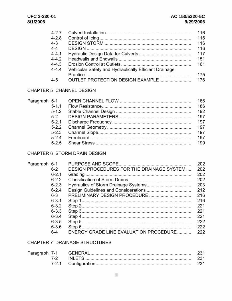
4-2.7 Culvert Installation................................................................... 116 4-2.8 Control of Icing........................................................................ 116 4-3 DESIGN STORM .................................................................... 116 4-4 DESIGN .................................................................................. 116 4-4.1 Hydraulic Design Data for Culverts ......................................... 117 4-4.2 Headwalls and Endwalls ......................................................... 151 4-4.3 Erosion Control at Outlets ....................................................... 161 4-4.4 Vehicular Safety and Hydraulically Efficient Drainage
Practice ................................................................................... 175 4-5 OUTLET PROTECTION DESIGN EXAMPLE......................... 176
CHAPTER 5 CHANNEL DESIGN
OPEN CHANNEL FLOW ........................................................ 186Paragraph 5-1 5-1.1 Flow Resistance...................................................................... 186 5-1.2 Stable Channel Design ........................................................... 192 5-2 DESIGN PARAMETERS......................................................... 197 5-2.1 Discharge Frequency .............................................................. 197 5-2.2 Channel Geometry .................................................................. 197 5-2.3 Channel Slope......................................................................... 197 5-2.4 Freeboard ............................................................................... 197 5-2.5 Shear Stress ........................................................................... 199
CHAPTER 6 STORM DRAIN DESIGN
PURPOSE AND SCOPE......................................................... 202Paragraph 6-1 6-2 DESIGN PROCEDURES FOR THE DRAINAGE SYSTEM .... 202 6-2.1 Grading ................................................................................... 202 6-2.2 Classification of Storm Drains ................................................. 202 6-2.3 Hydraulics of Storm Drainage Systems................................... 203 6-2.4 Design Guidelines and Considerations ................................... 212 6-3 PRELIMINARY DESIGN PROCEDURE ................................. 216 6-3.1 Step 1...................................................................................... 216 6-3.2 Step 2...................................................................................... 221 6-3.3 Step 3...................................................................................... 221 6-3.4 Step 4...................................................................................... 221 6-3.5 Step 5...................................................................................... 222 6-3.6 Step 6...................................................................................... 222 6-4 ENERGY GRADE LINE EVALUATION PROCEDURE........... 222
CHAPTER 7 DRAINAGE STRUCTURES
Paragraph 7-1 GENERAL............................................................................... 231 7-2 INLETS ................................................................................... 231 7-2.1 Configuration........................................................................... 231
iii

UFC 3-230-01 AC 150/5320-5C 8/1/2006 9/29/2006
7-2.2 Area Inlets............................................................................... 232 7-3 MANHOLES............................................................................ 235 7-3.1 Configuration........................................................................... 235 7-3.2 Chamber and Access Shaft .................................................... 236 7-3.3 Frames and Covers................................................................. 236 7-3.4 Channels and Benches ........................................................... 240 7-3.5 Manhole Depth........................................................................ 240 7-3.6 Location and Spacing.............................................................. 241 7-3.7 Settlement of Manholes .......................................................... 241 7-4 JUNCTION CHAMBERS......................................................... 242 7-5 MISCELLANEOUS STRUCTURES ........................................ 242 7-5.1 Chutes..................................................................................... 242 7-5.2 Security Fencing ..................................................................... 242 7-5.3 Fuel/Water Separators ............................................................ 245 7-5.4 Outlet Energy Dissipators ....................................................... 246 7-5.5 Drop Structures and Check Dams........................................... 247 7-5.6 Transitions .............................................................................. 247 7-5.7 Flow Splitters........................................................................... 247 7-5.8 Siphons ................................................................................... 248 7-5.9 Flap Gates .............................................................................. 249 7-6 DESIGN FEATURES .............................................................. 250 7-6.1 Grates ..................................................................................... 250 7-6.2 Ladders ................................................................................... 251 7-6.3 Steps....................................................................................... 254 7-7 SPECIAL DESIGN CONSIDERATIONS FOR AIRFIELDS ..... 254 7-7.1 Overview ................................................................................. 254 7-7.2 Recommended Design Parameters ........................................ 254
CHAPTER 8 STORM WATER CONTROL FACILITIES
GENERAL............................................................................... 257Paragraph 8-1 8-1.1 Storage and Detention/Retention Benefits .............................. 257 8-1.2 Design Objectives ................................................................... 258 8-2 ISSUES RELATED TO STORM WATER QUANTITY
CONTROL FACILITIES .......................................................... 258 8-2.1 Release Timing ....................................................................... 258 8-2.2 Safety...................................................................................... 259 8-2.3 Maintenance............................................................................ 260 8-3 STORAGE FACILITY TYPES ................................................. 261 8-3.1 Detention Facilities.................................................................. 261 8-3.2 Retention Facilities.................................................................. 262 8-3.3 Wet Pond Facilities ................................................................. 262 8-3.4 Infiltration Facilities.................................................................. 263
iv

UFC 3-230-01 AC 150/5320-5C 8/1/2006 9/29/2006
CHAPTER 9 PIPE SELECTION, BEDDING AND BACKFILL
GENERAL............................................................................... 264Paragraph 9-1 9-1.1 Pipe Selection ......................................................................... 264 9-1.2 Selection of n Values .............................................................. 264 9-1.3 Restricted Use of Bituminous-Coated Pipe ............................. 264 9-1.4 Classes of Bedding and Installation ........................................ 265 9-1.5 Strength of Pipe ...................................................................... 266 9-1.6 Rigid Pipe................................................................................ 266 9-1.7 Flexible Pipe............................................................................ 282 9-1.8 Bedding of Pipe (Culverts and Storm Drains) ......................... 282 9-2 FROST CONDITION CONSIDERATIONS.............................. 282 9-3 INFILTRATION OF FINE SOILS THROUGH DRAINAGE
PIPE JOINTS .......................................................................... 284 9-4 MINIMUM AND MAXIMUM COVER FOR AIRFIELDS ........... 285 9-5 MINIMUM AND MAXIMUM COVER FOR ROADWAYS ......... 286
CHAPTER 10 GUIDELINES FOR DESIGN IN THE ARTIC AND SUBARTIC
Paragraph 10-1 GENERAL............................................................................... 288 10-2 ICING ...................................................................................... 288 10-2.1 Description .............................................................................. 288 10-2.2 Types ...................................................................................... 288 10-2.3 Natural Factors Conducive to Icing Formation ........................ 290 10-2.4 Effects of Human Activities on Icing ........................................ 290 10-2.5 Methods of Counteracting Icing............................................... 291 10-3 GUIDELINES FOR DESIGN OF STORM DRAINS IN THE
ARCTIC AND SUBARCTIC..................................................... 297 10-4 GRADING ............................................................................... 299 10-5 TEMPORARY STORAGE....................................................... 299 10-6 MATERIALS............................................................................ 299 10-7 MAINTENANCE ...................................................................... 299 10-8 JOINTING ............................................................................... 299 10-9 END PROTECTION ................................................................ 299 10-10 ANCHORAGE AND BUOYANCY ........................................... 300 10-11 DEBRIS AND ICING CONTROL............................................. 300 10-12 TIDAL AND FLOOD EFFECTS............................................... 300 10-13 INSTALLATION....................................................................... 300
CHAPTER 11 WATER QUALITY CONSIDERATIONS
Paragraph 11-1 GENERAL............................................................................... 301 11-2 GENERAL BMP SELECTION GUIDANCE ............................. 301 11-3 ESTIMATING POLLUTANT LOADS ....................................... 304 11-4 EXTENDED DETENTION DRY PONDS................................. 304
v

UFC 3-230-01 AC 150/5320-5C 8/1/2006 9/29/2006
11-5 WET PONDS .......................................................................... 304 11-6 INFILTRATION/EXFILTRATION TRENCHES ........................ 304 11-7 INFILTRATION BASINS ......................................................... 305 11-8 SAND FILTERS ...................................................................... 305 11-9 WATER QUALITY INLETS ..................................................... 305 11-10 VEGETATIVE PRACTICES .................................................... 305 11-11 ULTRA-URBAN BMPs ............................................................ 305 11-12 TEMPORARY EROSION AND SEDIMENT CONTROL
PRACTICES............................................................................ 306
CHAPTER 12 DESIGN COMPUTER PROGRAMS
STORM WATER MANAGEMENT PROGRAMS .................. 307Paragraph 12-1 12-2 DRIP (DRAINAGE REQUIREMENT IN PAVEMENTS)........ 307 12-3 CANDE-89 (CULVERT ANALYSIS AND DESIGN) .............. 307 12-4 MODBERG........................................................................... 307 12-5 DDSOFT (DRAINAGE DESIGN SOFTWARE)..................... 307 12-6 NDSOFT (NORMAL DEPTH SOFTWARE).......................... 307 12-7 PIPECAR.............................................................................. 308 12-8 VISUAL URBAN (HY-22) URBAN DRAINAGE DESIGN
PROGRAMS ........................................................................ 308 12-9 ADDITIONAL SOFTWARE................................................... 308 12-9.1 HYDRAIN ............................................................................. 309 12-9.2 HYDRA................................................................................. 310 12-9.3 WSPRO................................................................................ 311 12-9.4 HYDRO ................................................................................ 311 12-9.5 HY8 ...................................................................................... 312 12-9.6 HYCHL ................................................................................. 312 12-9.7 NFF ...................................................................................... 313 12-9.8 HYEQT................................................................................. 313 12-9.9 TR-55 ................................................................................... 313 12-9.10 TR-20 ................................................................................... 314 12-9-11 HMS ..................................................................................... 315 12-9.12 HEC-RAS ............................................................................. 316 12-9.13 SWMM.................................................................................. 317 12-10 HYDRAULIC TOOLBOX (HY-TB) ........................................ 318 12-10.1 HY12 .................................................................................... 318 12-10.2 HY15 .................................................................................... 318 12-10.3 BASIN................................................................................... 318 12-10.4 SCOUR ................................................................................ 318 12-11 URBAN DRAINAGE DESIGN PROGRAMS......................... 319 12-11.1 Manning’s Equation .............................................................. 319 12-11.2 HEC-22................................................................................. 319 12-11.3 Stormwater Management ..................................................... 319 12-12 DR3M ................................................................................... 319
vi

UFC 3-230-01 AC 150/5320-5C 8/1/2006 9/29/2006
12-12.1 Rainfall-Excess Components ............................................... 319 12-12.2 Impervious Surfaces............................................................. 320 12-12.3 Routing ................................................................................. 320 12-12.4 Model Versatility ................................................................... 320 12-12.5 Urban Basin Planning........................................................... 320 12-12.6 Usability................................................................................ 320 12-13 EVALUATION OF WATER QUALITY................................... 320 12-14 SOFTWARE AVAILABILITY................................................. 321
GLOSSARY ................................................................................................ 324
APPENDIX A REFERENCES........................................................................ 328
APPENDIX B LIST OF CHARTS................................................................... 334
APPENDIX C LIST OF SYMBOLS ................................................................ 385
APPENDIX D BIBLIOGRAPHY ..................................................................... 390
APPENDIX E WAIVER PROCESSING PROCEDURES FOR DOD ............. 398
APPENDIX F WAIVER PROCESSING PROCEDURES FOR FAA .............. 402
INDEX ................................................................................................ 406
FIGURES
Figure Title
2-1 Example IDF Curve .............................................................................. 13 2-2 SCS 24-hr Rainfall Distribution ............................................................. 14 2-3 Approximate Geographic Areas for SCS Rainfall Distributions............. 14 2-4 Dimensionless Curvilinear SCS Synthetic Unit Hydrograph and
Equivalent Triangular Hydrograph........................................... 37 2-5 Example: The Triangular Unit Hydrograph .......................................... 39 3-1 Typical Gutter Sections ........................................................................ 44 3-2 Conveyance–Spread Curves for a Composite Gutter Section.............. 49 3-3 Classes of Storm Drain Inlets ............................................................... 63 3-4 P-1-7/8 and P-1-7/8 x 4 Grate (Same as P-1-7/8 Grate Without
3/8-in. Transverse Rods)......................................................... 67 3-5 P-1-1/8 Grate........................................................................................ 68 3-6 Curved Vane Grate............................................................................... 69 3-7 45-Degree 2-1/4 and 45-Degree 3-1/4 Tilt-bar Grates.......................... 70 3-8 30-Degree 3-1/4 Tilt-bar Grates ........................................................... 71
vii
UFC 3-230-01 AC 150/5320-5C 8/1/2006 9/29/2006
3-9 Reticuline Grate.................................................................................... 72 3-10 Depressed Curb-opening Inlet.............................................................. 80 3-11 Definition of Depth ................................................................................ 87 3-12 Curb-Opening Inlets ............................................................................. 92 3-13 Inlet Spacing Computation Sheet ......................................................... 97 3-14 Example of Flanking Inlets ................................................................... 100 3-15 Median Drop Inlet ................................................................................. 103 3-16 Embankment Inlet and Downdrain........................................................ 111 4-1 Inlet Control .......................................................................................... 118 4-2 Headwater Depth for Concrete Pipe Culverts with Inlet Control ........... 119 4-3 Headwater Depth for Oval Concrete Pipe Culverts Long Axis
Vertical with Inlet Control ........................................................ 120 4-4 Headwater Depth for Oval Concrete Pipe Culverts Long Axis
Horizontal with Inlet Control .................................................... 121 4-5 Headwater Depth for Corrugated Metal Pipe Culverts with Inlet
Control .................................................................................... 122 4-6 Headwater Depth for Structural Plate and Standard Corrugated
Metal Pipe-Arch Culverts with Inlet Control ............................. 123 4-7 Headwater Depth for Box Culverts with Inlet Control............................ 124 4-8 Headwater Depth for Corrugated Metal Pipe Culverts with Tapered
Inlet Inlet Control ..................................................................... 125 4-9 Headwater Depth for Circular Pipe Culverts with Beveled Ring Inlet
Control .................................................................................... 126 4-10 Outlet Control ....................................................................................... 127 4-11 Head for Circular Pipe Culverts Flowing Full, n = 0.012 ....................... 130 4-12 Head for Oval Circular Pipe Culverts Long Axis Horizontal or
Vertical Flowing Full, n = 0.012 ............................................... 131 4-13 Head for Circular Pipe Culverts Flowing Full, n = 0.024 ....................... 132 4-14 Head for Circular Pipe Culverts Flowing Full, n = 0.0328 to 0.0302 ..... 133 4-15 Head for Standard Corrugated Metal Pipe-Arch Culverts Flowing
Full, n = 0.024 ......................................................................... 134 4-16 Head for Field-Bolted Structural Plate Pipe-Arch Culverts 18 in.
Corner Radius Flowing Full, n = 0.0327 to 0.0306 .................. 135 4-17 Head for Concrete Box Culverts Flowing Full, n = 0.012...................... 136 4-18 Tailwater Elevation at or Above Top of Culvert..................................... 137 4-19 Tailwater Below the Top of the Culvert................................................. 137 4-20 Circular Pipe Critical Depth................................................................... 139 4-21 Oval Concrete Pipe Long Axis Horizontal Critical Depth ...................... 140 4-22 Oval Concrete Pipe Long Axis Vertical Critical Depth .......................... 141 4-23 Standard Corrugated Metal Pipe-Arch Critical Depth ........................... 142 4-24 Structural Plate Pipe-Arch Critical Depth.............................................. 143 4-25 Critical Depth Rectangular Section....................................................... 144 4-26 Culvert Design Form............................................................................. 146 4-27 Culvert Headwalls and Wingwalls......................................................... 152 4-28 Types of Scour at Storm Drain and Culvert Outlets.............................. 154
viii

UFC 3-230-01 AC 150/5320-5C 8/1/2006 9/29/2006
4-29 Square Culvert Froude Number............................................................ 155 4-30 Predicted Scour Depth vs. Observed Scour Depth............................... 156 4-31 Predicted Scour Width vs. Observed Scour Width ............................... 157 4-32 Predicted Scour Length vs. Observed Scour Length............................ 158 4-33 Predicted Scour Volume vs. Observed Scour Volume ......................... 159 4-34 Dimensionless Scour Hole Geometry for Minimum Tailwater............... 160 4-35 Dimensionless Scour Hole Geometry for Maximum Tailwater.............. 160 4-36 Recommended Size of Protective Stone .............................................. 162 4-37 Length of Stone Protection, Horizontal Blanket .................................... 163 4-38 Recommended Configuration of Riprap Blanket Subject to
Minimum and Maximum Tailwaters......................................... 164 4-39 Preformed Scour Hole .......................................................................... 165 4-40 Culvert Outlet Erosion Protection, Lined Channel Expansion............... 166 4-41 Maximum Permissible Discharge for Lined Channel Expansions......... 166 4-42 Flared Outlet Transition ........................................................................ 167 4-43 Stilling Well ........................................................................................... 169 4-44 U.S. Bureau of Reclamation Impact Basin ........................................... 170 4-45 Saint Anthony Falls Stilling Basin ......................................................... 171 4-46 Design Chart for SAF Stilling Basin ...................................................... 172 4-47 Recommended Riprap Sizes................................................................ 174 4-48 Scour Hole Riprap Sizes ...................................................................... 175 5-1 Distribution of Shear Stress.................................................................. 193 5-2 Shear Stress Distribution in Channel Bends......................................... 195 5-3 Channel Geometries............................................................................. 198 6-1 Storm Drain Capacity Sensitivity .......................................................... 206 6-2 Hydraulic and Energy Grade Lines in Pipe Flow .................................. 210 6-3 Preliminary Storm Drain Computation Sheet ........................................ 220 6-4 Energy and Hydraulic Grade Line Illustration ....................................... 223 6-5 Energy Grade Line Computation Sheet – Table A................................ 225 6-6 Energy Grade Line Computation Sheet – Table B................................ 226 7-1 Inlet Structures ..................................................................................... 232 7-2 Typical Inlet Design for Storm Drainage Systems ................................ 233 7-3 Repair Area Inlets................................................................................. 234 7-4 Standard Storm Drain Manhole ............................................................ 237 7-5 Standard Precast Manholes ................................................................. 238 7-6 Junction Details for Large Pipes ........................................................... 238 7-7 Typical Manhole Configurations ........................................................... 239 7-8 “Tee” Manhole for Large Storm Drains ................................................. 240 7-9 Efficient Channel and Bench Configurations ........................................ 243 7-10 Details of Typical Drainage Chute ........................................................ 244 7-11 Outlet Security Barrier .......................................................................... 245 7-12 Transitions to Avoid Obstruction........................................................... 248 7-13 Twin-Barrel Siphon ............................................................................... 249 7-14 Examples of Typical Inlet Grates .......................................................... 252 7-15 Examples of Inlet Design...................................................................... 253
ix

UFC 3-230-01 AC 150/5320-5C 8/1/2006 9/29/2006
7-16 Type A – Bicycle Gear Configuration.................................................... 255 7-17 Type B – Tricycle Gear Configuration................................................... 255 7-18 Type C – Tricycle Gear Configuration .................................................. 256 8-1 Hydrograph Schematic ......................................................................... 257 8-2 Example of a Cumulative Hydrograph with and without Detention ....... 259 9-1 Three Main Classes of Conduits........................................................... 266 9-2 Free-Body Conduit Diagrams ............................................................... 267 9-3 Trench Beddings for Circular Pipe........................................................ 268 9-4 Beddings for Positive Projecting Conduits............................................ 269 9-5 Installation Conditions that Influence Loads on Underground
Conduits.................................................................................. 269 10-1 Typical Cross Section of a Frost Belt Installation.................................. 296 10-2 Earth Embankments with Impervious Barriers...................................... 297
TABLES
Table Title
2-1 Runoff Coefficients for Rational Formula.............................................. 16 2-2 Manning’s Roughness Coefficient (n) for Overland Sheet Flow ........... 19 2-3 Intercept Coefficients for Velocity vs. Slope Relationship of
Equation 2-4............................................................................ 20 2-4 Values of Manning’s Coefficient (n) for Channels and Pipes................ 21 2-5 Nationwide Urban Equations Developed by the USGS ........................ 26 2-6 Runoff Curve Numbers for Urban Areas (Average Watershed
Condition, Ia =0.2SR) ............................................................... 29 2-7 Adjustment Factor (Fp) for Pond and Swamp Areas that are Spread
Throughout the Watershed ..................................................... 30 2-8 Tabular Hydrograph Unit Discharges for Type II Rainfall
Distributions ............................................................................ 33 2-9 Subarea and Composite Hydrographs ................................................. 36 3-1 Manning’s n for Street and Pavement Gutters...................................... 46 3-2 Spread at Average Velocity in a Reach of Triangular Gutter ................ 61 3-3 Average Debris Handling Efficiencies of Grates Tested ....................... 73 3-4 Grate Efficiency and Capacity Summary .............................................. 79 3-5 Comparison of Inlet Interception Capacities ......................................... 86 3-6 Distance to Flanking Inlets in a Sag Vertical Curve Using Depth at
Curb Criteria............................................................................ 102 3-7 Grate Ranking with Respect to Bicycle and Pedestrian Safety ............ 112 4-1 Entrance Loss Coefficients, Outlet Control, Full or Partly Full
V 2
H = K Entrance Head Loss,
e e 2g ........................................... 128 5-1 Manning’s n for Natural Stream Channels (Surface Width at Flood
Stage Less than 100 ft) ........................................................... 187
x
UFC 3-230-01 AC 150/5320-5C 8/1/2006 9/29/2006
5-2 Manning’s Roughness Coefficients for Lined Channels ....................... 187 5-3 Classification of Vegetal Covers as to Degree of Retardance .............. 188 5-4 Manning’s n Relationships for Vegetal Degree of Retardance ............. 189 5-5 Permissible Shear Stresses for Lining Materials .................................. 199 6-1 Manning’s Coefficients for Storm Drain Conduits ................................. 205 6-2 Increase in Capacity of Alternate Conduit Shapes Based on a
Circular Pipe with the Same Height......................................... 207 6-3 Frequencies for Coincidental Occurrence ............................................ 212 6-4 Minimum Pipe Slopes to Ensure 3.0 ft/s Velocity in Storm Drains
Flowing Full ............................................................................. 216 7-1 Manhole Spacing Criteria ..................................................................... 241 7-2 Transition Design Criteria ..................................................................... 248 9-1 Suggested Maximum Cover Requirements for Concrete Pipe,
Reinforced Concrete, H-20 Highway Loading ......................... 270 9-2 Suggested Maximum Cover Requirements for Corrugated
Aluminum Alloy Pipe, Riveted, Helical, or Welded Fabrication 2.66-in. Spacing, 0.5-in.-Deep Corrugations, H-20 Highway Loading............................................................ 271
9-3 Suggested Maximum Cover Requirements for Corrugated Steel Pipe, 2.66-in. Spacing, 0.5-in.-Deep Corrugations .................. 272
9-4 Suggested Maximum Cover Requirements for Structural Plate Aluminum Alloy Pipe, 9-in. Spacing, 2.5-in Corrugations ........ 273
9-5 Suggested Maximum Cover Requirements for Corrugated Steel Pipe, 5-inch Span, 1-inch-Deep Corrugations......................... 274
9-6 Suggested Maximum Cover Requirements for Structural Plate Steel Pipe, 6-in. Span, 2-in.-Deep Corrugations .............................. 275
9-7 Suggested Maximum Cover Requirements for Corrugated Steel Pipe, 3-in. Span, 1-in. Corrugations ........................................ 277
9-8 Suggested Guidelines for Minimum Cover ........................................... 278 9-9 Minimum Depth of Cover in Feet for Pipe Under Flexible Pavement
(Part 1) .................................................................................... 279 9-9 Minimum Depth of Cover in Feet for Pipe Under Flexible Pavement
(Part 2) .................................................................................... 280 9-9 Minimum Depth of Cover in Feet for Pipe Under Flexible Pavement
(Part 3) .................................................................................... 281 11-1 BMP Selection Criteria ......................................................................... 302 11-2 Pollutant Removal Comparison for Various Urban BMP Designs......... 303 12-1 Software Versus Capabilities Matrix ..................................................... 309 12-2 Software Program Contact Information ................................................ 321
xi
Top Related