


Languages
Pages
Legal


A Review of Antennas for Wireless
Communication Devices
Sunakshi Puri1, Kiranpreet Kaur
1, and Naveen Kumar
2
1Electronics & Communication Department, Baba Banda Singh Bahadur Engineering College, Punjab, India
2Electronics & Communication Department, Universal Inst. of Engineering & Technology, Punjab, India
Email: [email protected], [email protected], [email protected]
Abstract—The extensive demand for mobile communication
and information exchange through wireless devices has lead
to major achievements in antenna designing. The purpose of
the paper is to give a frame of reference, understanding, and
overview of antennas used in wireless communication
devices. In this paper we will be discussing various antennas,
their advantages and drawbacks. Also a brief framework of
comparisons between various antennas is presented on the
basis of various parameters. This paper also summarizes the
benefits and use of PIFA for USB dongle to cover the
WiMAX bands.
Index Terms—PIFA, USB dongle, WiMAX, antennas
I. INTRODUCTION
Wireless communication have progressed so fast in
recent years, it requires small equipments supporting
multiband communication. As an essential part of the
communication system, antenna is one of the most
significant design issues. As we concern about small
equipments we require antennas which are small in size
and light in weight [1]. Due to its compact size Planner
inverted-F antennas (PIFAs) are most suitable to be
employed in wireless equipments. The major advantages
of PIFA are its simple structure, easy fabrication and less
manufacturing cost. PIFA is a promising antenna for the
future technology due to adjustability of its structure [2].
PIFA structure is widely used for internal mobile handset
antenna. But its narrow bandwidth makes it difficult for it
to be used as multiband antenna. So researchers have
analyzed, designed and tested several techniques through
which multiband operation can be achieved from PIFA
structure.
A multiband antenna utilized in a mobile
communication system can operate at distinct frequency
band. Presently, the mobile communication system uses
frequency bands such as GSM 850 (824-894MHz), GSM
900 (890-960MHz), GSM 1900 (1850-1990MHz),
UMTS (1920-2170MHz), Bluetooth (2.4-2.48GHz) and
WLAN (5.16-5.5GHz) [3]. WiMAX is designed in such a
manner that it supports 30 to 40Mbps data rates. WiMAX
has three licensed spectrum profiles i.e. low band, middle
band and high band. Low band has frequency ranging
Manuscript received August 5, 2013; revised January 12, 2014.
from 2.5 to 2.8GHz, the middle band has frequency
ranging from 3.2 to 3.8GHz and high band has 5.2 to
5.8GHz.
USB can provide connection to WiMAX via a device
called dongle. Universal Serial Bus (USB) dongles are
used for providing plug-and-play functionality in devices
such as laptops. Future wireless USB dongles should
have capability of accommodating high data rates to
provide various multimedia services. By using two
printed Dual-band PIFAs, a Dual-band Multi Input Multi
Output (MIMO) antenna can be made in order to
implement 4G USB Dongle application [4]-[6]. A vast
range of application uses PIFA as their antenna element
including wearable devices, wireless sensors, RFID and
UWB systems with adaptive antennas covering an
available wide frequency band of GSM 850 (824-
890MHz), GSM 900 (890-960MHz), DCS/GSM 1800
(1710-1880MHz), WiBro (2.300-2.4GHz), Bluetooth
(2.4-2.48GHz), and UMTS.
II. WIDEBAND ANTENNAS
Wideband antenna has remarkable ability to be
designed for wireless and radio frequency electronics.
Wideband antennas are different from broadband
antennas, as in wideband antennas pass band is large, but
radiation pattern and antenna gain may not be the same
over the pass band. Wideband antennas need larger space
to be installed as compared to multiband antennas.
Microstrip patch antenna comes under the category of
wideband antennas and they are also known as printed
antennas. Fig. 1 shows a basic microstrip antenna. The
advantages like light in weight, low cost and providing
both linear and circular polarization makes them popular
[2]. Using it with its original configuration, this type of
antenna has a narrow bandwidth and low gain. But by
using a suitable technique such as stacked patch i.e.
making the substrate thick or using a low permittivity
substrate its bandwidth can be widened.
But increase in substrate thickness over a limit may
lead to decrease in efficiency of microstrip antennas. The
increase in substrate thickness also results in increase in
probe length. Increase in probe length also increases
probe inductance which may lead to impedance matching
problems.
199
International Journal of Electronics and Electrical Engineering Vol. 2, No. 3, September, 2014
©2014 Engineering and Technology Publishingdoi: 10.12720/ijeee.2.3.199-201
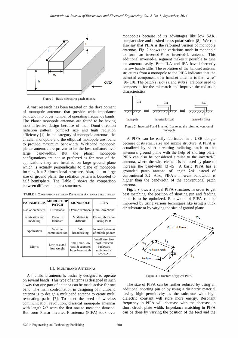
Figure 1. Basic microstrip patch antenna
A vast research has been targeted on the development
of monopole antennas that provide wide impedance
bandwidth to cover number of operating frequency bands.
The Planar monopole antennas are found to be having
most affective design because of their Omni-direction
radiation pattern, compact size and high radiation
efficiency [1]. In the category of monopole antennas, the
circular monopole and the elliptical monopole are found
to provide maximum bandwidth. Wideband monopole
planar antennas are proven to be the best radiators over
large bandwidths. But the planar monopole
configurations are not so preferred as for most of the
applications they are installed on large ground plane
which is actually perpendicular to plane of monopole
forming it a 3-dimensional structure. Also, due to large
size of ground plane, the radiation pattern is bounded to
half hemisphere. The Table I shows the comparison
between different antenna structures.
TABLE I. COMPARISON BETWEEN DIFFERENT ANTENNA STRUCTURES
PARAMETERS MICROSTRIP
PATCH MONOPOLE PIFA
Radiation pattern Directional Omni-directional Omni-directional
Fabrication and
modeling
Easier to
fabricate
Modeling is
difficult
Easier fabrication
using PCB
Application Satellite
communication Radio
broadcasting Internal antennas of mobile phones
Merits Low cost and
low weight
Small size, low
cost & supports large bandwidth
Small size, low
cost, reduced
backward radiation i.e.
Low SAR
III. MULTIBAND ANTENNAS
A multiband antenna is basically designed to operate
on several bands. This type of antenna is designed in such
a way that one part of antenna can be made active for one
band. The main confrontation in designing of multiband
antenna is to design a multiband antenna to create multi
resonating paths [7]. To meet the need of wireless
communication revolution, classical monopole antennas
with length λ/2 were the first one to meet the demand.
But soon Planar inverted-F antenna (PIFA) took over
monopoles because of its advantages like low SAR,
compact size and desired cross polarization [8]. We can
also say that PIFA is the reformed version of monopole
antennas. Fig. 2 shows the variations made in monopole
to form an inverted-F or inverted-L antenna. This
additional inverted-L segment makes it possible to tune
the antenna easily. Both ILA and IFA have inherently
narrow bandwidths. The evolution of the handset antenna
structures from a monopole to the PIFA indicates that the
essential component of a handset antenna is the “wire”
[9]-[10]. The patch(s) slot(s), and stub(s) are only used to
compensate for the mismatch and improve the radiation
characteristics.
Figure 2. Inverted-F and Inverted-L antenna the reformed version of
monopole
A PIFA can be easily fabricated in a USB dongle
because of its small size and simple structure. A PIFA is
actualized by short circuiting radiating patch to the
antenna’s ground plane with the help of shorting plate.
PIFA can also be considered similar to the inverted-F
antenna, where the wire element is replaced by plate to
increase the bandwidth [3]-[5]. A basic PIFA has a
grounded patch antenna of length λ/4 instead of
conventional λ/2. Also, PIFA’s inherent bandwidth is
higher than the bandwidth of the conventional patch
antenna.
Fig. 3 shows a typical PIFA structure. In order to get
best matching, the position of shorting pin and feeding
point is to be optimized. Bandwidth of PIFA can be
improved by using various techniques like using a thick
air substrate or by varying the size of ground plane.
Figure 3. Structure of typical PIFA
The size of PIFA can be further reduced by using an
additional shorting pin or by using a dielectric material
having high permittivity as the substrate with high
dielectric constant will store more energy. Resonant
frequency in PIFA will decrease with the decrease in
short circuit plate width. Impedance matching in PIFA
can be done by varying the position of the feed and the
200
International Journal of Electronics and Electrical Engineering Vol. 2, No. 3, September, 2014
©2014 Engineering and Technology Publishing

shorting pins and optimizing the space between them [6]-
[8]. The only disadvantage of PIFA over other antennas is
that, due to its quarter wavelength patch, the gain of PIFA
is reduced but the size is reduced to 50%.
IV. CONCLUSION
In this paper, we have compared all the antennas on the
basis of their design and different parameters that can be
designed to work for wireless equipment. From the above
discussion, we concluded that Planar Inverted-F Antenna
(PIFA) stood above all other antenna designs due to its
various advantages like small in size and easy fabrication.
Due to these advantages PIFA can be used in small
devices like a USB dongle in order to cover the desired
Wireless range of frequencies.
REFERENCES
[1] K. L. Wong, Planar Antennas for Wireless Communication, John
Wiley & Sons Inc., 2003. [2] H. Wong, K. M. Luk, C. H. Chan, Q. Xue, K. K. So, and H. W.
Lai, “Small antennas in wireless communications,” in Proc. the
IEEE, vol. 100, no. 7, 2012, pp. 2109-2121. [3] J. A. Ray and S. R. B. Chaudhuri, “A review of PIFA technology,”
in Proc. 2011 Indian Antenna Week (IAW), Kolkata, 2011, pp. 1-
4. [4] W. S. Chen, B. Y. Lee, J. J. Lu, K. M. Lin, C. Y. Huang, and C.
K. Yang, “A PIFA type USB dongle antenna for WLAN
applications,” in Proc. Cross Strait Quad-Regional Radio Science and Wireless Technology Conference, Chengdu, 2013, pp. 203-
206.
[5] Y. Belhadef and N. B. Hacene, “PIFA antennas design for mobile communications,” in Proc. 7th International Workshop on
Systems, Signal Processing and their Applications, Tipaza, 2011,
pp. 119-122. [6] W. C. Su and K. L. Wong, “Internal PIFAs for
UMTS/WLAN/WiMAX multi-network operation for a USB
dongle,” Microwave Optical Technology Letters, vol. 48, pp. 2249-2253, 2006.
[7] X. Jing, Z. Du, and K. Gong, “A compact multiband planar
antenna for mobile handsets,” IEEE Antennas and Wireless
Propagation Letters, vol. 5, no. 1, pp. 343-345, 2006.
[8] C. Rowell and E. Y. Lam, “Mobile-phone antenna design,” IEEE
Antennas and Propagation Magazine, vol. 54, no. 4, pp. 14-34,
2012. [9] H. F. AbuTarboush, R. Nilavalan, T. Peter, and S. W. Cheu,
“Multiband inverted-f antenna with independent bands for small
and slim cellular mobile handsets,” IEEE Transactions on Antennas and Propagation, vol. 59, no. 7, pp. 2636-2645, 2011.
[10] Y. X. Guo, M. Y. W. Chia, and Z. N. Chen, “Miniature built-in
multiband antennas for mobile handsets”, IEEE Transactions on Antennas and Propagation, vol. 52, no. 8, pp. 1936-1944, 2004.
Sunakshi Puri was born on 28th, December
1986 in Chandigarh, India. .She received her Bachelor of Technology Degree in Electronics
& Communication Engineering from Sri
Sukhmani Institute of Engineering & Technology, Punjab, India (2009). She is
pursuing Master of Technology Degree from
Baba Banda Singh Bahadur Engineering College, Punjab, India. She has more than 3
years of academic experience. Her areas of
interests are Wireless & Mobile Communication and Antenna Design.
Kiranpreet Kaur was born in Faridkot,
Punjab. She received her Bachelor of
Technology Degree in Electronics & Communication Engineering from T.I.E.T.
Patiala, Punjab in 2000. She has completed
Master of Technology Degree from PTU Jalandhar, Punjab in 2007. She is Pursuing
PhD in Wireless Communication from PTU
Jalandhar, Punjab. Presently, she is working as an assistant professor in Baba Banda Singh
Bahadur Engineering College, Fatehgarh,
Punjab. She has more than 12 years of academic experience. She has more than 19 papers published in National/International conferences.
Her research area is wireless and mobile communication.
Naveen Kumar was born on 16th, October 1987 in Chandigarh, India. He received his
Bachelor of Technology Degree in Electronics
& Communication Engineering from Swami
Vivekanand Institute of Engineering &
Technology, Punjab, India (2009). He has
completed Master of Engineering from National Institute of Technical Teachers’
Training & Research (NITTTR), Chandigarh,
India (2013). Presently, he is working as an Assistant Professor, Electronics &
Communication Department, Universal Group of Institutions, Punjab,
India. He has 3 years of academic experience. His research interests are Wireless & Mobile communication & Antenna Design.
201
International Journal of Electronics and Electrical Engineering Vol. 2, No. 3, September, 2014
©2014 Engineering and Technology Publishing
Top Related