


Languages
Pages
Legal

The 14th IFToMM World Congress, Taipei, Taiwan, October 25-30, 2015 DOI Number: 10.6567/IFToMM.14TH.WC.OS8.002
A Novel Fuzzy Optimal Controller on Motion and Vibration Coordination Control
for a Multi-flexible Link Manipulator
Ji Wang Yangjun Pi Yumei Hu Xiansheng Gong
State Key Laboratory State Key Laboratory State Key Laboratory College of Mechanical
of Mechanical Transmission, of Mechanical Transmission, of Mechanical Transmission, Engineering,
Chongqing University Chongqing University Chongqing University Chongqing University
Chongqing, China Chongqing, China Chongqing, China Chongqing, China
[email protected] cqpp@ cqu.edu.cn [email protected] [email protected]
Abstract
In this paper, a new motion and vibration coordination
controller - a Fuzzy Linear Quadratic Regulator (FLQR)
controller is proposed for the control of a multi-flexible link
manipulator. The FLQR controller bases on the dynamic model
of multi-flexible link manipulators, which is based on the finite
element method(FEM) and the Lagrange equation. Then a
synthesized LQR controller in which both rigid-body motion
and elastic deformation are considered, is combined with a
fuzzy controller to adjust weight ratio between motion state
variables and vibration state variables in weight matrix of LQR
online, according to motion and vibration feedback information.
The performance of the FLQR controller is compared with that
of previous typical motion and vibration controllers based on a
flexible four-bar linkage in simulation. Results show that the
proposed controller is more effective on motion and vibration
coordination control.
Key words: LQR, fuzzy controller, flexible manipulators,
trajectory tracking , vibration control
1 Introduction
The important trends in the development of
industrial robots are light weight and high speed, leading
to advantages such as lower energy consumption, faster
response and lower overall cost[1]. At the same time, the
flexibility of modern machines brings challenges into
modeling and control accordingly. For modeling of
flexible manipulators, the popular methods are the finite
element method (FEM) and the assumed-mode method
based on either the Lagrange equation or the
Newton–Euler recursive formulation. For control of
flexible manipulators, the main difficulty is the
interaction between the objective motion and undesired
vibration. In other words, motion control and vibration
control should be considered simultaneously in controller
design. It is the research hotspot and the great challenge
for researchers in this field.
The model of flexible manipulators is a distributed
parameter system, which is built by partial differential
equations (PDEs). In general, PDEs are divided into a
finite number of ordinary differential equations (ODEs)
by the FEM [2,3] or the assumed-mode method [4,5]
with linearization, in order to apply existing control
techniques such as PD control [6], model predictive
control [7], adaptive control [8], sliding control[9],
singular perturbation approach [10] et al. These control
methods have been applied in single flexible link
manipulators successfully. However, control of
multi-flexible link manipulators is a more difficult task
than that of single flexible link manipulators, since it is a
more complex nonlinear model. Some researchers
proposed the control method based on smart materials
featuring distributed actuators, such as piezoelectric
patches (PZTs)[11,12]. However this is not economical
from the practical point of view due to the requirement of
additional actuators and their accessories. Therefore
research focused on collected actuator control and it is
classified into feedforward type and feedback type. The
typical one in the first type is the input shaping
technique[13]. Whereas the drawback of this method is
that the expected trajectory may be affected or even
altered by shaping process. Hence the feedback type has
been paid more attention in recent years. In this field, the
most representative control methods are PID+SRF(strain
rate feedback)[14],sliding control[15], LQR[16] and so
on. In these control methods, the common problem
which needs to be solved is that motion control and
vibration suppression affect each other. Specially, in
PID+SRF controller,PID is responsible for motion
control and SRF is used to reduce vibration
independently at the same time. Unfortunately, the
vibration control force from SRF would degrade the
motion control precision of PID. Reciprocally, the
differential function in PID would excite further
vibration of flexible linkages. In LQR, the weight
coefficient ratio between motion state variables and
vibration state variables is difficult to be defined. It
means a hard balance between motion control and
vibration suppression. Overall, the common exiting
problem of aforementioned control methods is that
motion control and vibration suppression can not be
coordinated sufficiently .
In this paper, a fuzzy linear quadratic regulator
(FLQR) is proposed for the first time in our knowledge.
A LQR controller in which both rigid-body motion and
elastic deformation are considered, is combined with a
fuzzy controller to adjust the weight ratio between
motion and vibration control to different situations,
according to the feedback information on vibration
amplitude. The relation of motion control and vibration
suppression can be coordinated well without sudden
change and high frequency changes during process of
real-time adjustment. It guarantees high-precision of
motion and vibration control in the process of
manipulator movement.
The paper is organized as follows: Section 2 briefly
outlines the general dynamic model of the planar
multi-flexible link manipulators derived by the finite
element method and the Lagrange equation. In Section 3
the FLQR controller is described. In Section4, the
numerical simulation on a flexible four-bar linkage is
carried out. Finally, the conclusions of this work are
provided in Section 5.
2. Multi-flexible link manipulator dynamic model
The combination of FEM and Lagrange equation is
a general method[17-19] in modeling of planar
multi-flexible link manipulator, shown in Fig 1. Firstly,
the multi-flexible link manipulator is divided into several
elastic beams by the FEM. Define as
elastic generalized coordinates in an elastic element,
representing nodal elastic displacements of the elastic
beam element in the local reference. The elastic
displacements can indicate the amplitude of vibration.
Define as system’s elastic generalized
coordinates, representing all nodal elastic displacements
of the multi-flexible link manipulator in the fixed
reference. Let f be the number of the system elastic
generalized coordinates. Define as the
rigid-body generalized coordinates, representing joint
angular displacements in accordance with rigid-body
degrees of freedom. d is the number of the rigid-body
generalized coordinates. The Rayleigh damping
coefficients are introduced into the system. And these
hypotheses [20,21] are adopted to simplify model: 1) the
instantaneous structure hypothesis; 2) total motion
composites of the large rigid-body motion and the small
elastic deflection; 3) the high level minim in the
elastodynamic equation can be neglected. Consequently,
a suitable dynamic model meeting the need of online
control of multi-flexible link manipulator can be written
as:
(1)
Where and are an elastic mass matrix and
rigid mass matrix respectively, and are
rigid-elastic coupling mass matrices. , , ,
are elements in the damping matrix and is a flexural
structure stiffness matrix. is a vector of the driving
forces of actuators. is a vector of the generalized
forces corresponding to the system’s elastic generalized
coordinates, only including external forces because the
interaction forces between different elastic elements offset
each other. is a vector of the generalized forces
corresponding to the rigid-body generalized coordinates.
Defining , a compact form of Eq. (1) can be
expressed as
(2)
Where
The above dynamic equation also can be rearranged as
(3)
Taking as the augmented

state vector, Eq. (3) can be expressed as
(4)
Where
Therefore the state equation of the multi- flexible
link manipulator can be given by
(5)
Where , , is the input variable
vector for the multi-flexible link manipulator. H is
temporary identity matrix. If the measured state variable
is taken into consideration, H should be changed
accordingly and the appropriate observer should be
added into system to estimate state variables.
Fig 1. General planar multi-flexible link manipulators. Detailed view of a deformed beam element (Inset).
3. FLQR system
A fuzzy linear quadratic regulator(FLQR) is proposed
in this paper for the first time. In this controller, the
weight ratio L between motion state variables and
vibration state variables can be adjusted online by fuzzy
method according to feedback information on vibration
amplitude. The traditional LQR for motion and vibration
control adopts constant weight ratio of above two types
of state variables. It is unable to get good results for both
motion and vibration control due to the phenomenon that
which state variable weight is high, the corresponding
error with the desired value is small. Therefore it is a
hard choice between motion control and vibration
suppression. The proposed fuzzy linear quadratic
regulator can distribute the weights of motion control and
vibration control to adapt to different situations online.
The diagram of FLQR controller can be seen in Fig 2
Fig.2 The diagram of FLQR system
The goal of the synthesized LQR controller is to
seek the optimal control force ( )t to minimize the
performance index J ,defined as:
(6)
Where is the feedback state variable
vector,
is
the objective state variable vector. and
stand for the joint objective angular velocities and the
joint objective angular displacements. It is worthwhile to
note that minimizes the absolute values of nodal
elastic displacements, nodal elastic velocities, errors of
joint angular displacements and errors of joint angular
velocities. The performance index reaches a minimum
value as long as the control force is defined as
(7)
Where the optimal control gain matrix is
defined as
(8)
And is the solution of the Riccati equation as follow
(9)
Where , are time-varying coefficient matrices of the
state - space Eq.(5). Hence the Riccati equation must be
solved online within a certain control period. According
to the characteristic of the infinite time LQR, the Riccati
Eq.(9) is an algebraic equation which can satisfy the
demand for online computing. The matrix in Eq.(9)
contains the weights of the control motor torques. The
matrix which contains the weights of all state
variables in the state - space Eq. (5) can be defined as
Q .
represent the
weights of elements in , ,
represent the weights of elements in and
represent the weights of
tracking errors of . L is the ratio of weights of
tracking errors to the weights of elastic displacements in
. L is an important factor for the motion control and
vibration suppression performance of the synthesized
LQR controller. The precision of motion control shows a
positive correlation with L and the effect of vibration
suppression shows a negative correlation with L in its
valid range.
L would be adjusted to different situations online in
the proposed controller. It should be noted that high
frequency changes and steps of weights may cause
system parameter perturbation which would excite high
frequency vibration in turn. Therefore, we use the fuzzy
algorithm to adjust the weight ratio L, which can avoid
the high frequency changes and steps with an appropriate
set of membership functions and fuzzy inference rules.
The input of the fuzzy controller is the equal envelope
curve (EEC) of the elastic displacement of the midpoint
in the longest flexible link. The EEC is constituted of two
stages. Stage1 is the constant compensation and stage 2
is the envelope curve gained by real-time rectification
and filtering of elastic displacement of the midpoint in
the longest flexible link. At the beginning, the curve
value is a constant KC , which compensates the lag of
envelope detection. The switch index from stage1 to
stage2 is:
(10)
Where are values of the envelope curve at
adjacent sampling points respectively. So Eq. (10) means
the switch point of EEC is the first peak point of
envelope curve.
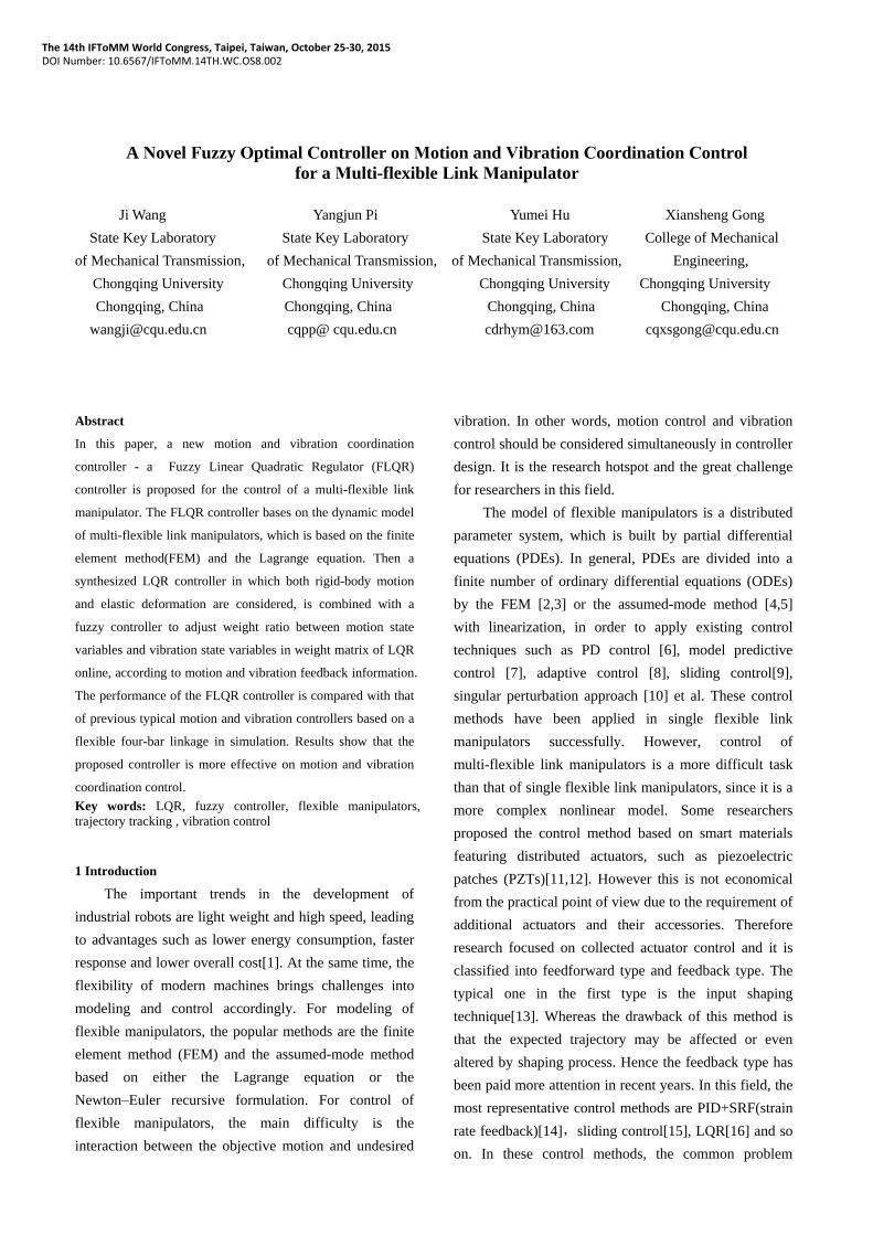
The EEC is converted into the input variable fuzzy
field through scaling factor 1/Kf . There are two input
variable membership functions, and they should be
located in proper location with relatively large overlap to
avoid mutation. The membership functions used in
simulation for a flexible four-bar linkage is shown in
Fig.3.
Fig.3(a) Membership functions for input of the fuzzy controller
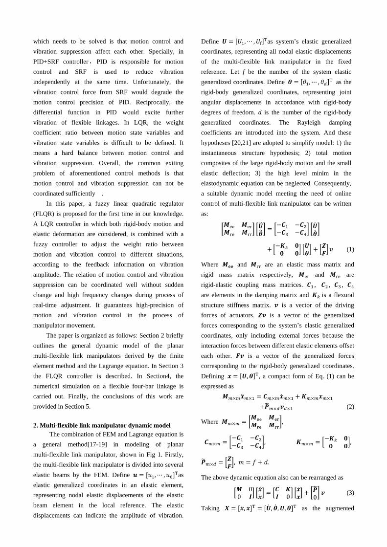
Fig.3(b) Membership functions for output of the fuzzy controller
The fuzzy rule is adopted to avoid high frequent changes
of weight ratio L .The fuzzy rule is shown in Tab1. The
Output of fuzzy controller is the weight ratio L, which is
sent to the LQR controller to renew the weight
distribution of motion control and vibration suppression
online.
Tab.1 The fuzzy inference rule in FLQR
fuzzy variables fuzzy inference rule
input B S
output S B
4. Simulation on a flexible four-bar linkage
4.1 Model of the flexible four-bar linkage
To prove the effectiveness of the proposed FLQR
controller, it is applied on a flexible four-bar linkage,
which is shown in Fig.1 with N=4. So the system elastic
generalized coordinates are and the
rigid-body generalized coordinate is . The system
parameters of the flexible four-bar linkage are given in
Tab 2.
deg
ree
of
mem
ber
ship
d
egre
e o
f m
emb
ersh
ip
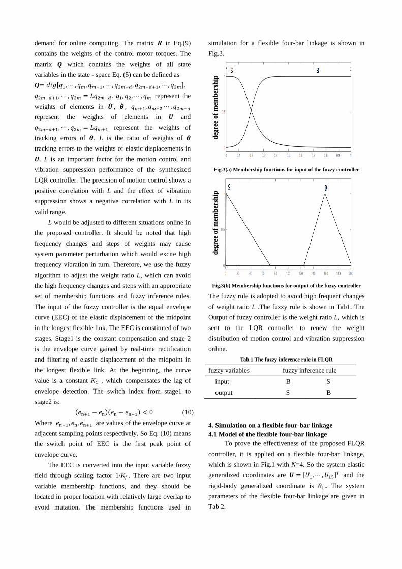
Tab.2 Kinematic and dynamic features of the flexible four-bar linkage under investigation.
Items Parameter values of the model
Link length Link1
0.358m
Link2
0.530m
Link3
0.639m
Fixed link
0.329m
Concentrated masses
and inertias
Joint 2(mass)
0.030 kg
Joint 3(mass)
0.030 kg
Joint4 (inertia)
1.156×10⁻⁴kg m2
Square cross-section 6 mm×6 mm
Density 7.5×10⁻³kg/m3
Modulus of elasticity 193×109N/m2
The concrete form of matrices in model of the
flexible four-bar linkage according to Eq. (1) is written as
follow:
Elastic mass matrix are:
(11)
Where , are the density and the sectional area of the
beam element; is the shape function matrix of the ith
elastic beam element in the local coordinate system
shown in Fig.1 (insert):
is the coordinate transformation matrix, the
transformation from the global coordinate system to the
ith element local coordinate system:
(12)
Where represent respectively. is
the angle between the local coordinate system of the ith
element and the global coordinate system. which
consists of 1 or 0 is a matrix which represents the
transformation from the system elastic generalized
coordinates to the ith element elastic generalized
coordinates .
Rigid-elastic coupling mass matrix are:
(13)
is a sensitivity matrix [3] which represents the
relationship between the joint angular velocity of
link 1 and the rigid-body nodal velocities.
Rigid mass matrix are:
(14)
Where are the moments of inertia of link 1,
link2 and link3, respectively. is mass of the link 2.
are elements of which
respectively represent the gain coefficient from the joint
angular velocity of link 1 to the velocity in the
X-direction ,the velocity in the Y-direction, the angular
velocity of the midpoint of link 2 and the angular
velocity of the joint 4 (the last joint).
Damping matrix are:
(15)
(16)
(17)
Stiffness matrix are:
(18)
Where is the material’s elastic modulus and is the
cross sectional moment of inertia.
Generalized forces corresponding to the system
elastic generalized coordinates are:
(19)
Where is the ith element generalized forces
vector which corresponds to the elastic generalized
coordinates of the ith element.
4.2 simulation result
The step and sine object trajectories are used to test
the performance of the FLQR controller. The Final
position of step is 0.5 (rad), the sine object trajectory is
defined as
(rad) (20)
The control parameters of FLQR, LQR and PD+SRF in
two simulation cases are shown below.

Tab 3. Control parameters of controllers.
Step(position control)
Sine(trajectory tracking)
Controller Control parameters Control parameters
FLQR Kf=1.6×10⁻³ KC=1.3×10⁻³ Kf=1.2×10⁵ KC=1.2×10⁻⁵
LQR L=80 L=80
PD+SRF kp=21
The input and output of FLQR controller, EEC
multiplied by scaling factor and weight ratio L adjusted
online, shown in Fig.4 and Fig.5.
Fig.4 The curve of equal envelope curve(EEC) multiplied
by scaling factor
Fig.5 The curve of weight ratio L
With the proposed appropriate fuzzy controller,
online adjusting of the weight ratio L is achieved without
sudden changes and high frequency changes, which
avoid further vibration stimulation and achieve
coordinating motion control and vibration control well.
4.2.1 Step object trajectory
Under the objective position 0.5rad for joint space,
the response of joint 1 angular displacement and the
elastic displacement of the midpoint in the longest
flexible are shown in Fig.6 and Fig.7 respectively.
Fig.6 The elastic displacement of the midpoint in link3
Fig.7 The response of joint1 angular displacement
It can be seen from Fig.6 that the vibration
amplitude and decay time of the FLQR controller are
smaller than other two controllers. It means the proposed
controller possesses better vibration suppression,
compared to previous LQR and PID+SRF. From Fig.7, it
can be concluded that motion control of the PID+SRF
controller is worst among above controllers. The undue
overshoot appeared in the response of joint 1 angular
displacement, because differential coefficient in PID is
subject to vibration. The effect of motion control in
FLQR and traditional LQR is similar. The response time
of FLQR is slightly longer than that of LQR, because the
FLQR pay more attention on vibration suppression in the

start-up stage when the vibration is violent. The
difference in response time of FLQR and LQR is small
enough to be ignored, as opposed to the advantage in
vibration suppression of FLQR.
4.2.2 Sine object trajectories
Under the sine object trajectory for joint space, the
effects of vibration suppression and motion control are
shown in Fig.8 and Fig.9 respectively.
Fig.8 The elastic displacement of the midpoint in link3
Fig.9 The tracking error of joint1 angular displacements
The elastic displacements of the midpoint of the 3rd
flexible link and tracking errors of joint1 under the sine
objective trajectory Eq.(20) are shown in Fig.8 and Fig.9.
The similar result with previous simulation is that the
vibration suppression of FLQR controller is better than
that of LQR and PID+SRF. The tracking error of FLQR
in the stable stage is much smaller than others, although
its tracking error at the start-up stage is larger than other
two controllers. It needs to be emphasized that the more
important index of motion control is errors in the stable
stage rather than start-up stage, because people pay more
attention on motion trail in work stage of manipulators.
5 Conclusion
In this paper, a new motion and vibration
coordination controller (FLQR) is proposed for a
multi-flexible link manipulator. The FLQR controller can
adjust the weight ratio L of the motion state variables to
the vibration state variables in weight matrix of LQR
online by a fuzzy controller. It can redistribute the
weights of motion control and vibration control
according to different feedback information on vibration
state of manipulators, without sudden changes and high
frequency changes which may excite high frequency
vibration. Hence the FLQR controller can coordinate the
motion control and vibration suppression well. Both step
and sine object trajectories were taken to test the
performance of the FLQR controller and previous two
typical motion and vibration controllers. The results
show that the FLQR controller has better behavior on
trajectory tracking and vibration suppression than
traditional LQR and PID+SRF and its position control
effect is very close to that of LQR with ignorable
difference, which is the best position control among these
controllers. It has successfully been verified that the
FLQR controller can guarantee high-precision motion
and vibration control in process of manipulator
movement. Without loss of generality, the proposed
controller can be applied to the control for general
flexible manipulators.
However, the differences between the above
dynamic model of the multi-flexible link manipulator and
the actual multi-flexible link manipulator often appear in
engineering practice. Therefore, our future work would
add robust into proposed control system to compensate
the uncertainty between the dynamic model and the
actual multi-flexible link manipulator.
Acknowledgement
The authors gratefully acknowledge the financial support
from the National Basic Research Program of China(973)
[2014CB049403], the National Basic Research Program
of China(973) [2014CB049404] and the Special
Research Fund for the Doctoral Program of Higher
Education [20130191110004].

Reference
[1] Alaa Shawkya, Dawid Zydeka and Yehia Z. Elhalwagy,
Modeling and nonlinear control of a flexible-link
manipulator. Applied Mathematical
Modelling :37(23):9591-9602, 2013.
[2]Thompson B , Sung C , A survey of finite element
techniques for mechanism design. Mechanism and Machine
Theory 21(4): 351-359, 1986.
[3]Gasparetto A. Accurate modelization of a flexible-link planar
mechanism by means of a linearized model in the
state–space form for design of a vibration controller.
Journal of Sound and Vibration 240(2):241–62, 2001.
[4]Yoo W and Haug E. Dynamics of flexible mechanical
systems using vibration and static correction modes.
Journal of Mechanical Design 108(3): 315-322, 1986.
[5]Wei He, Shuang Zhang and Shuzhi Sam Ge. Adaptive
Control of a Flexible Crane System With the Boundary
Output Constraint. IEEE Transactions on Industrial
Electronics 61(8):4126-4133, 2014.
[6]Ge SS, Lee TH and Zhu G. Improving regulation of a
single-link flexible mechanism with strain feedback. IEEE
Transactions on Robotics and Automation 14(1): 179-185,
1998.
[7] Rickey Dubay, Marwan Hassan and Chunying Li. Finite
element based model predictive control for active vibration
suppression of a one-link flexible manipulator. ISA
Transactions 53(5):1609-1619, 2014.
[8]Shaheed MH and Tokhi O. Adaptive closed-loop control of a
single-link flexible mechanism. Journal of Vibration and
Control 19(13): 2068-2080, 2013.
[9]Gabriela Mamani, Jonathan Becedas and Vicente Feliu.
Sliding mode tracking control of a very lightweight
single-link flexible robot robust to payload changes and
motor friction. Journal of Vibration and control 18(8):
1141-1155, 2012.
[10] J. Lina and F.L.Lewisb. Two-time scale fuzzy logic
controller of flexible link robot arm. Fussy Sets and System
139 (1): 125-149,2003.
[11]Kang B and Mills JK. Vibration control of a planar parallel
mechanism using piezoelectric actuators. Journal of
Intelligent and Robotic Systems 42(1): 51-70, 2005.
[12]Zhang X, Mills JK, Cleghorn WL, Experimental
implementation on vibration mode control of a moving
3-PRR flexible parallel mechanism with multiple PZT
transducers. Journal of Vibration and Control 16:
2035–2054, 2010.
[13]Singhose WE, Singer NC, Effects of input shaping on
two-dimensional trajectory following. IEEE Transactions
on Robotics and Automation 12(6): 881-887, 1996.
[14]Caracciolo R, Trevisani A, Simultaneous rigid-body motion
and vibration control of a flexible four-bar linkage.
Mechanism and Machine Theory 36(2): 221-243, 2001.
[15]Utkin VA, Control of elastic multi-link mechanisms based
on the dynamic compensation method, In: Proceedings of
the IEEE International Symposium on Circuits and
Systems, Moscow(Russia), pp. 594–597,1998.
[16]Gasparetto A, Zanotto V, Vibration reduction in a
flexible-link mechanism through synthesis of an optimal
controller. Meccanica 41:611-622, 2006.
[17]Nagarajan S, Turcic DA, Lagrangian formulation of the
equations of motion for elastic mechanisms with mutual
dependence between rigid-body and elastic motions. Part I:
Element level equations and Part II: systems equations.
Journal of Dynamic Systems, Measurement and Control,
Transactions of the ASME 112(2):215–224, 1990.
[18]Zhang C, Analysis and design of elastic linkage
mechanisms. Beijing: Machine Press, pp:73-78, 1997,.
[19]Gurses K, Bradley J. Buckham, Edward J. Park, Vibration
control of a single-link flexible mechanism using an array
of fiber optic curvature sensors and PZT actuators.
Mechatronics 19(2): 167–177, 2009.
[20]Turcic DA., Midha A., Dynamic Analysis of Elastic
Mechanism Systems, PartI: Applications. Journal of
Dynamic Systems, Measurement and Control, Transactions
of the ASME 106(4): 249-254, 1984.
[21]Giovagnoni M, A note on planar kineto-elasto-dynamics.
Meccanica 23:170-178, 1998.
Top Related