


Languages
Pages
Legal


Answers for energy
7SR21 & 7SR22 ArgusOvercurrent Relay
Reyrolle
Protection
Devices

7SR210 & 7SR220 Description of Operation
The copyright and other intellectual property rights in this document, and in any model or article produced from it(and including any registered or unregistered design rights) are the property of Siemens Protection DevicesLimited. No part of this document shall be reproduced or modified or stored in another form, in any data retrievalsystem, without the permission of Siemens Protection Devices Limited, nor shall any model or article bereproduced from this document unless Siemens Protection Devices Limited consent.
While the information and guidance given in this document is believed to be correct, no liability shall be acceptedfor any loss or damage caused by any error or omission, whether such error or omission is the result ofnegligence or any other cause. Any and all such liability is disclaimed.
©2015 Siemens Protection Devices Limited
7SR210 Non-Directional Relay
7SR220 Directional Relay
Description Of Operation

7SR210 & 7SR220 Description of Operation
©2015 Siemens Protection Devices Limited Page 2 of 85
Document Release HistoryThis document is issue 2015/07. The list of revisions up to and including this issue is: -
2011/05 First issue.
2013/01 Typographical revisions and added data. Updated in line with software release.
2014/06 Typographical revisions and added data. Updated in line with software release.
2015/06 Typographical revisions amended drawings and added data. Updated in line with softwarerelease.
2015/07 Amended drawings.
Software Revision History2011/05 2435H85008R7a-7a (7SR210)
2435H85009R7a-7a (7SR220)
First Release
2013/01 2435H85008R7c-7b (7SR210)
2435H85009R7c-7b (7SR220)
Introduced journaling file system.Added 61850 logical nodes for CB Counters, metering, 50BF,46BC, 81HBL2 and line check.Added Line Check on non-AR devices.Added 74CCS Close Circuit Supervision.
2014/06 2435H85008R7f-7d (7SR210)
2435H85009R7f-7d (7SR220)
Added Fault Locator feature and Check Sync feature.Fault data transmission over IEC 60870-5-103.Additional communications data, control features, meters.
2015/06 2435H85008R8a-7f (7SR210)
2435H85009R8a-7f (7SR220)
Added Power Factor Meters, Load Blinding feature, Arc FlashDetector. Over current TM Setting Range extended.

7SR210 & 7SR220 Description of Operation
©2015 Siemens Protection Devices Limited Page 3 of 85
ContentsDocument Release History ................................................................................................................................. 2Software Revision History .................................................................................................................................. 2Contents ............................................................................................................................................................ 3List of Figures .................................................................................................................................................... 5Section 1: Introduction ....................................................................................................................................... 8
1.1 Current Transformer Circuits .............................................................................................................. 81.2 External Resistors.............................................................................................................................. 81.3 Fibre Optic Communication ................................................................................................................ 81.4 Front Cover ....................................................................................................................................... 8
Section 2: Hardware Description ...................................................................................................................... 152.1 General ........................................................................................................................................... 152.2 Case ............................................................................................................................................... 152.3 Front Cover ..................................................................................................................................... 162.4 Power Supply Unit (PSU) ................................................................................................................. 162.5 Operator Interface/ Fascia................................................................................................................ 162.6 Current Inputs.................................................................................................................................. 212.7 Voltage Inputs ................................................................................................................................. 212.8 Binary Inputs ................................................................................................................................... 212.9 Binary Outputs (Output Relays) ........................................................................................................ 222.10 Virtual Input/Outputs ........................................................................................................................ 232.11 Self Monitoring ................................................................................................................................ 23
2.11.1 Protection Healthy/Defective ............................................................................................... 23Section 3: Protection Functions ........................................................................................................................ 24
3.1 Current Protection: Phase Overcurrent (67, 51, 50) ........................................................................... 243.1.1 Directional Control of Overcurrent Protection (67) – 7SR22 ................................................. 243.1.2 Instantaneous Overcurrent Protection (50) .......................................................................... 263.1.3 Time Delayed Overcurrent Protection (51) .......................................................................... 27
3.2 Current Protection: Voltage Controlled Overcurrent (51V) – 7SR22 ................................................... 293.3 Current Protection: Derived Earth Fault (67N, 51N, 50N)................................................................... 30
3.3.1 Directional Control of Derived Earth Fault Protection (67N) – 7SR22.................................... 303.3.2 Instantaneous Derived Earth Fault Protection (50N) ............................................................ 313.3.3 Time Delayed Derived Earth Fault Protection (51N) ............................................................. 32
3.4 Current Protection: Measured Earth Fault (67G, 51G, 50G)............................................................... 343.4.1 Directional Control of Measured Earth Fault Protection (67G) – 7SR22 ................................ 343.4.2 Instantaneous Measured Earth Fault Protection (50G) ......................................................... 353.4.3 Time Delayed Measured Earth Fault Protection (51G) ......................................................... 36
3.5 Current Protection: Sensitive Earth Fault (67SEF, 51SEF, 50SEF) .................................................... 373.5.1 Directional Control of Sensitive Earth Fault Protection (67SEF) – 7SR22 ............................. 373.5.2 Instantaneous Sensitive Earth Fault Protection (50SEF) ...................................................... 38
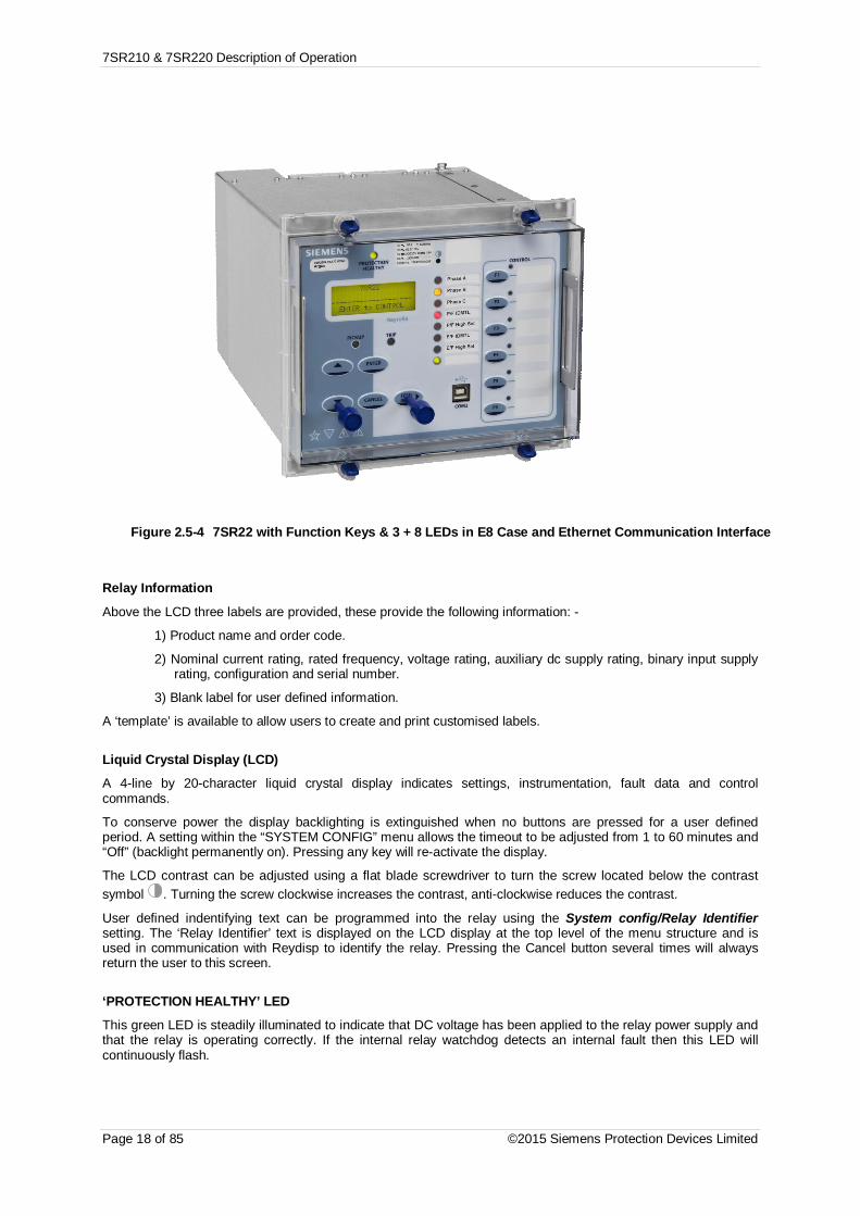
3.6 Current Protection: High Impedance Restricted Earth Fault (64H) ..................................................... 403.7 Current Protection: Cold Load (51c) ................................................................................................. 413.8 Current Protection: Negative Phase Sequence Overcurrent (46NPS) ................................................ 423.9 Current Protection: Under-Current (37, 37G & 37SEF) ...................................................................... 433.10 Current Protection: Under-Current Guarded (37) ............................................................................... 433.11 Current Protection: Thermal Overload (49) ....................................................................................... 443.12 Current Protection: Arc Flash Detector (50 AFD) ............................................................................... 463.13 Voltage Protection: Phase Under/Over Voltage (27/59) - 7SR22 ....................................................... 473.14 Voltage Protection: Negative Phase Sequence Overvoltage (47) – 7SR22 ........................................ 483.15 Voltage Protection: Neutral Overvoltage (59N) – 7SR22 ................................................................... 493.16 Voltage Protection: Under/Over Frequency (81) – 7SR22.................................................................. 50
Section 4: Control & Logic Functions ................................................................................................................ 514.1 Auto-Reclose (79) ............................................................................................................................ 51
4.1.1 Overview............................................................................................................................ 514.1.2 Auto Reclose sequences .................................................................................................... 53
4.2 Autoreclose Prot’n Menu .................................................................................................................. 544.3 Autoreclose Config Menu ................................................................................................................. 544.4 P/F Shots Sub-Menu........................................................................................................................ 564.5 E/F Shots Sub-Menu........................................................................................................................ 564.6 SEF Shots Sub-Menu ...................................................................................................................... 564.7 Extern Shots Sub-Menu ................................................................................................................... 574.8 Manual Control ................................................................................................................................ 594.9 Synchronising .................................................................................................................................. 60
4.9.1 Reclosure Modes ............................................................................................................... 604.9.2 Charge Delays ................................................................................................................... 60

7SR210 & 7SR220 Description of Operation
Page 4 of 85 ©2015 Siemens Protection Devices Limited
4.9.3 Voltage monitoring elements .............................................................................................. 604.9.4 Check Synchronising Mode ................................................................................................ 624.9.5 System Split Detector ........................................................................................................ 634.9.6 System Sync Reversion ..................................................................................................... 634.9.7 System Synchronising Mode .............................................................................................. 644.9.8 Close on Zero Mode .......................................................................................................... 64
4.10 Live/Dead Indication ........................................................................................................................ 654.11 Circuit Breaker ................................................................................................................................ 664.12 Quick Logic ..................................................................................................................................... 68
Section 5: Supervision Functions ..................................................................................................................... 705.1 Circuit Breaker Failure (50BF) ......................................................................................................... 705.2 VT Supervision (60VTS) – 7SR22 .................................................................................................... 715.3 Busbar VT Fail (60VTF-Bus) – 7SR22 ............................................................................................. 725.4 CT Supervision (60CTS & 60CTS-I) ................................................................................................. 73
5.4.1 (60CTS-I) – 7SR21 & 7SR22 ............................................................................................. 735.4.2 (60CTS) – 7SR22 .............................................................................................................. 73
5.5 Broken Conductor (46BC) ............................................................................................................... 745.6 Trip / Close Circuit Supervision (74TCS & 74CCS) ........................................................................... 745.7 Inrush Restraint (81HBL2) ............................................................................................................... 755.8 Load Blinder (21) ............................................................................................................................ 76
5.8.1 Load Blinder (21) Three-Phase .......................................................................................... 765.8.2 Load Blinder (21) Single-Phase. ......................................................................................... 77
Section 6: Other Features ................................................................................................................................ 796.1 Data Communications ..................................................................................................................... 796.2 CB Maintenance ............................................................................................................................. 79
6.2.1 Output Matrix Test ............................................................................................................. 796.3 Data Storage................................................................................................................................... 80
6.3.1 General ............................................................................................................................. 806.3.2 Event Records ................................................................................................................... 806.3.3 Waveform Records. ........................................................................................................... 806.3.4 Fault Records .................................................................................................................... 816.3.5 Demand ............................................................................................................................ 816.3.6 Data Log ........................................................................................................................... 816.3.7 Energy Storage ................................................................................................................. 826.3.8 Fault Locator ..................................................................................................................... 83
6.4 Metering ......................................................................................................................................... 836.5 Operating Mode .............................................................................................................................. 846.6 Control Mode .................................................................................................................................. 846.7 Real Time Clock .............................................................................................................................. 84
6.7.1 Time Synchronisation - Data Communication Interface ....................................................... 856.7.2 Time Synchronisation – Binary Input .................................................................................. 856.7.3 Time Synchronisation – IRIG-B (Optional) .......................................................................... 85
6.8 Settings Groups .............................................................................................................................. 856.9 Password Feature ........................................................................................................................... 85

7SR210 & 7SR220 Description of Operation
©2015 Siemens Protection Devices Limited Page 5 of 85
List of FiguresFigure 1.4-1 Functional Diagram of 7SR21 Relay .............................................................................. 10Figure 1.4-2 Connections Diagram for 7SR21 Relay ......................................................................... 11Figure 1.4-3 Functional Diagram of 7SR22 Relay .............................................................................. 13Figure 1.4-4 Connection Diagram for 7SR22 Relay ........................................................................... 14Figure 2.5-1 7SR21 with 3 + 8 LEDs in E6 Case ............................................................................... 16Figure 2.5-2 7SR220 with 3 + 16 LEDs in E8 Case ........................................................................... 17Figure 2.5-3 7SR22 with Function Keys and 3 + 8 LEDs in E8 Case .................................................. 17Figure 2.5-4 7SR22 with Function Keys & 3 + 8 LEDs in E8 Case and Ethernet
Communication Interface ............................................................................................... 18Figure 2.8-1 Binary Input Logic.......................................................................................................... 21Figure 2.9-1 Binary Output Logic ....................................................................................................... 22Figure 2.11-1 Start-up Counter Meter ................................................................................................ 23Figure 3.1.1-1 Logic Diagram: Directional Overcurrent Element (67) ............................................. 25Figure 3.1.2-1 Logic Diagram: Instantaneous Over-current Element .............................................. 26Figure 3.1.3-1 Logic Diagram: Time Delayed Overcurrent Element ............................................... 28Figure 3.2-1 Logic Diagram: Voltage Controlled Overcurrent Protection............................................. 29Figure 3.3.1-1 Logic Diagram: Derived Directional Earth Fault Element ......................................... 31Figure 3.3.2-1 Logic Diagram: Derived Instantaneous Earth Fault Element ................................... 32Figure 3.3.3-1 Logic Diagram: Derived Time Delayed Earth Fault Protection ................................. 33Figure 3.4.1-1 Logic Diagram: Measured Directional Earth Fault Protection .................................. 34Figure 3.4.2-1 Logic Diagram: Measured Instantaneous Earth-fault Element ................................. 35Figure 3.4.3-1 Logic Diagram: Measured Time Delayed Earth Fault Element (51G) ...................... 36Figure 3.5.1-1 Logic Diagram: SEF Directional Element (67SEF) .................................................. 37Figure 3.5.2-1 Logic Diagram: SEF Instantaneous Element .......................................................... 38Figure 3.5.2-2 Logic Diagram: SEF Time Delayed Element (51SEF) ............................................. 39Figure 3.6-1 Logic Diagram: High Impedance REF (64H) .................................................................. 40Figure 3.7-1 Logic Diagram: Cold Load Settings (51c) ....................................................................... 41Figure 3.8-1 Logic Diagram: Negative Phase Sequence Overcurrent (46NPS) .................................. 42Figure 3.9-1 Logic Diagram: Undercurrent Detector (37, 37G & 37SEF) ............................................ 43Figure 3.10-1 Logic Diagram: Undercurrent Guarded Detector (37) .............................................. 43Figure 3.11-1 Logic Diagram: Thermal Overload Protection (49S) ................................................ 45Figure 3.12-1 Logic Diagram: Arc Flash Detector (50 AFD) .......................................................... 46Figure 3.13-1 Logic Diagram: Under/Over Voltage Elements (27/59) ........................................... 47Figure 3.14-1 Logic Diagram: NPS Overvoltage Protection (47) ................................................... 48Figure 3.15-1 Logic Diagram: Neutral Overvoltage Element ......................................................... 49Figure 3.16-1 Logic Diagram: Under/Over Frequency Detector (81) ............................................. 50Figure 4.1.2-1 Typical Sequence with 3 Instantaneous and 1 Delayed trip .................................... 53Figure 4.7-1 Basic Auto-Reclose Sequence Diagram ........................................................................ 58Figure 4.9.3-1 Voltage Detector Operation .................................................................................... 61Figure 4.9.4-1 Check Sync Function ............................................................................................. 62Figure 4.9.7-1 System Sync Function ........................................................................................... 64Figure 4.9.8-1 Close On Zero Function ......................................................................................... 65Figure 4.9.8-2 Close On Zero Timing ............................................................................................ 65Figure 4.10-1 Voltage Detector Operation .................................................................................... 66Figure 4.11-1 Logic Diagram: Circuit Breaker Status .................................................................... 67Figure 4.12-1Sequence Diagram: Quick Logic PU/DO Timers (Counter Reset Mode Off) .................. 69Figure 5.1-1 Logic Diagram: Circuit Breaker Fail Protection (50BF) ................................................... 70Figure 5.2-1 Logic Diagram: VT Supervision Function (60VTS) ......................................................... 72Figure 5.4.1-1 Logic Diagram: CT Supervision Function (60CTS-I) – 7SR21 & 7SR22 .................. 73Figure 5.4.2-1 Logic Diagram: CT Supervision Function (60CTS) – 7SR22 ................................... 73Figure 5.5-1 Logic Diagram: Broken Conductor Function (46BC) ....................................................... 74Figure 5.6-1 Logic Diagram: Trip Circuit Supervision Feature (74TCS) ............................................. 74Figure 5.6-2 Logic Diagram: Close Circuit Supervision Feature (74CCS) .......................................... 75Figure 5.7-1 Logic Diagram: Harmonic Block Feature (81HBL2) ........................................................ 75Figure 5.8.1-1 Logic Diagram: Load Blinder Three-Phase ............................................................. 76Figure 5.8.2-1 Logic Diagram: Load Blinder Single-Phase ............................................................ 77Figure 5.8.2-2 Load Blinder and Angle .......................................................................................... 78Figure 6.3.7-1 Energy Direction Convention .................................................................................. 82

7SR210 & 7SR220 Description of Operation
Page 6 of 85 ©2015 Siemens Protection Devices Limited
LIST OF TABLES
Table 1.4-1 Ordering Information – 7SR21 Non-Directional Overcurrent ............................................. 9Table 1.4-2 Ordering Information – 7SR22 Directional Overcurrent .................................................. 12Table 2.1-1 Summary of Overcurrent Relay Configurations .............................................................. 15Table 6.5-1 Operation Mode ............................................................................................................ 84

7SR210 & 7SR220 Description of Operation
©2015 Siemens Protection Devices Limited Page 7 of 85
Symbols and Nomenclature
The following notational and formatting conventions are used within the remainder of thisdocument:
· Setting Menu Location MAIN MENU>SUB-MENU
· Setting: Elem name -Setting
· Setting value: value
· Alternatives: [1st] [2nd] [3rd]
c
start
trip
Elem Starter
Elem Inhibit
Elem Reset Delay
c
Forward
Reverse
Elem Char Dir
Non-Dir
L1 Dir Blk
PhaseAFwd
Binary input signal
Binary Output visible to user
Digital signal to/from anotherelement
List of settings associated with a specificfunctionAppropriate list is TRUE when settingselected.
Digital signal not visible touser, internal to this element
IL1Analogue signal with signaldescription
Common setting for multiple functions
c
start
trip
Function.
Individual functions are enabled whenassociated control input (c) is TRUE.
Common control input (c) for multiplefunctions. All functions are enabledwhen control input is TRUE.
&And Gate(2 inputs shown)
1Or Gate(3 inputs shown)
INST.
EVENTEVENT: IEC, Modbus or DNPWhere applicable
Relay instrument
1Exclusive Or (XOR) Gate(3 inputs shown)

7SR210 & 7SR220 Description of Operation
Page 8 of 85 ©2015 Siemens Protection Devices Limited
Section 1: Introduction
This manual is applicable to the following relays:
· 7SR210 Multi-Function Non-directional Overcurrent and Earth Fault Relay
· 7SR220 Multi-Function Directional Overcurrent and Directional Earth Fault Relay
The 7SR210 and 7SR220 relays integrate the protection and control elements required to provide a completeovercurrent based protection.
The ‘Ordering Options’ Tables summarise the features available in each model.
General Safety Precautions
1.1 Current Transformer CircuitsThe secondary circuit of a live CT must not be open circuited. Non-observance of this precaution can result ininjury to personnel or damage to equipment.
1.2 External ResistorsWhere external resistors are fitted to the circuit, these may present a danger of electric shock or burns, if touched.
1.3 Fibre Optic CommunicationWhere fibre optic communication ports are fitted, the lasers are Class 1 devices but recommend they should notbe viewed directly. Optical power meters should be used to determine the operation or signal level of the device.
1.4 Front CoverThe front cover provides additional securing of the relay element within the case. The relay covershould be in place during normal operating conditions.
!
!
!
!

7SR210 & 7SR220 Description of Operation
©2015 Siemens Protection Devices Limited Page 9 of 85
Table 1.4-1 Ordering Information – 7SR21 Non-Directional Overcurrent
Product description Variants Order No.
7 S R 2 1 0 - 1 A - 0 A 0
Protection Product FamilyOvercurrent - Non Directional 1
Relay Type0
Case, I/O and Fascia 1)
E6 case, 4 CT, 9 Binary Inputs, 8 Binary Outputs, 8 LEDs 2E8 case, 4 CT, 19 Binary Inputs, 16 Binary Outputs, 16 LEDs 3E8 case, 4 CT, 19 Binary Inputs, 16 Binary Outputs, 8 LEDs + 6 keys 4
Measuring input1 A or 5 A, 50/60Hz 1
Auxiliary voltage30 V to 220 V DC, binary input threshold 19 V DC A30 V to 220 V DC, binary input threshold 88 V DC B
SpareA
Communication InterfaceStandard version - included in all models, USB front port, RS485 rear port 1Standard version - plus additional rear F/O ST connectors (x2) and IRIG-B 2Standard version - plus additional rear RS485 and IRIG-B 3Standard version - plus additional rear RS232 and IRIG-B 4Standard version - plus additional rear Electrical Ethernet RJ45 (x2) 7 7Standard version - plus additional rear Optical Ethernet Duplex (x2) 8 7
ProtocolIEC 60870-5-103 and Modbus RTU (user selectable) 1IEC 60870-5-103 and Modbus RTU and DNP 3.0 (user selectable) 2IEC 60870-5-103 and Modbus RTU and DNP 3.0 (user selectable) and IEC61850 7-8 7
Spare0
Protection Function PackagesStandard version - included in all models C37 Undercurrent46BC Broken conductor/load unbalance46NPS Negative phase sequence overcurrent49 Thermal overload50 Instantaneous phase fault overcurrent50BF Circuit breaker fail50G/50N Instantaneous earth fault/SEF50 AFD Arc Flash Detector51 Time delayed phase fault overcurrent51G/51N Time delayed earth fault/SEF60CTS-I CT supervision64H High impedance REF74TC/CCS Trip & close circuit supervision81HBL2 Inrush restraint
Cold load pickupProgrammable logic
Standard version - plus D79 Autoreclose
Additional FunctionalityNo additional functionality A
Spare0
1) 4CT is configured as 3PF + EF/SEF (user selectable setting).

7SR210 & 7SR220 Description of Operation
©2015 Siemens Protection Devices Limited Page 10 of 85
Figure 1.4-1 Functional Diagram of 7SR21 Relay

7SR210 & 7SR220 Description of Operation
©2015 Siemens Protection Devices Limited Page 11 of 85
GND.
BI 1
+ve
-ve
+ve
-ve
IL1
(IA)
22
24
28
2
4
BI 2+ve
-ve
6
8
BI 3+ve
-ve
10
12
IL2
(IB)
IL3
(IC)
I4 (IG/ISEF)
13
14
15
16
BI 4+ve 18
BI 5+ve 20
BI 6+ve
-ve
22
25
BI 7+ve 24
BI 8+ve 26
BI 9+ve
-ve
28
27
BO 719
17
BO 823
21
1A
5A
1
2
3
4
1A
5A
5
6
7
8
1A
5A
9
10
11
12
1A
5A
7SR21
BI 10+ve
-ve
2
4
BI 11+ve
-ve
6
8
BI 12+ve10
BO 93
1
BO 107
5
BO 1111
9
BI 13+ve12
BI 14+ve14
BI 15+ve
-ve
16
18
BI 1620
BI 17+ve22
BI 18+ve24
BI 19+ve
-ve
26
28
+ve
BO 1215
13
21
19
17BO 13
BO 14
27
25
23BO 15
BO 16
A
Analogue
B
PSU
C
OptionalI/O
1 2
27 28
1 21 2
27 2827 28
DataComms
(Optional)
A
B
C
A
Screen
B
Term.
14
16
18
20
Rear ViewArrangement of terminals and modules
Shows contacts internal to relay caseassembly.Contacts close when the relay chassis iswithdrawn from case
NOTES
BI = Binary InputBO = Binary Output
BO 1
BO 2
9
5
7
BO 3
BO 4
BO 5
BO 6
27
3
1
15
11
13
19
17
23
21
25
26
Figure 1.4-2 Connections Diagram for 7SR21 Relay

7SR210 & 7SR220 Description of Operation
Page 12 of 85 ©2015 Siemens Protection Devices Limited
Table 1.4-2 Ordering Information – 7SR22 Directional Overcurrent
Product description Variants Order No.
7 S R 2 2 0 - 2 A - 0 A 0
Protection Product FamilyOvercurrent - Directional 2
Relay Type0
Case, I/O and Fascia 1)
E6 case, 5 CT, 4 VT, 3 Binary Inputs, 6 Binary Outputs, 8 LEDs 2 CE8 case, 5 CT, 4 VT, 13 Binary Inputs, 14 Binary Outputs, 16 LEDs 3E8 case, 5 CT, 4 VT, 13 Binary Inputs, 14 Binary Outputs, 8 LEDs + 6 keys 4
Measuring input1 A or 5 A, 40 V to 160 V, 50/60Hz 2
Auxiliary voltage30 V to 220 V DC, binary input threshold 19 V DC A30 V to 220 V DC, binary input threshold 88 V DC B
SpareA
Communication InterfaceStandard version - included in all models, USB front port, RS485 rear port 1Standard version - plus additional rear F/O ST connectors (x2) and IRIG-B 2Standard version - plus additional rear RS485 and IRIG-B 3Standard version - plus additional rear RS232 and IRIG-B 4Standard version - plus additional rear Electrical Ethernet RJ45 (x2) 7 7Standard version - plus additional rear Optical Ethernet Duplex (x2) 8 7
ProtocolIEC 60870-5-103 and Modbus RTU (user selectable) 1IEC 60870-5-103 and Modbus RTU and DNP 3.0 (user selectable) 2IEC 60870-5-103 and Modbus RTU and DNP 3.0 (user selectable) and IEC61850 7-8 7
Spare0
Protection Function PackagesStandard version - included in all models C21FL Fault Locator21LB Load Blinder27/591) Under/overvoltage37 Undercurrent37G1) Ground Undercurrent37SEF1) SEF Undercurrent46BC Broken conductor/load unbalance46NPS Negative phase sequence overcurrent471) Negative phase sequence voltage49 Thermal overload50 Instantaneous phase fault overcurrent50BF Circuit breaker fail50G/50N Instantaneous earth fault50 AFD Arc Flash Detector51V Voltage dependent overcurrent59N Neutral voltage displacement60CTS CT supervision60CTS-I CT supervision60VTS VT supervision64H High impedance REF67/50 Directional instantaneous phase fault overcurrent67/50G67/50N Directional instantaneous earth fault/SEF
67/51 Directional time delayed phase fault overcurrent67/51G67/51N Directional tIme delayed earth fault/SEF
74TC/CCS Trip & close circuit supervision81 Under/overfrequency81HBL2 Inrush restraint
Cold load pickupProgrammable logic
Standard version - plus D79 AutorecloseStandard version - plus E79 + 25
Additional FunctionalityNo additional functionality A
Spare0
1) 5CT is configured as 3PF + EF/SEF + EF/SEF (user selectable setting).
Autoreclose + Check Sync

7SR210 & 7SR220 Description of Operation
©2015 Siemens Protection Devices Limited Page 13 of 85
7SR22
46BC
46NPS(x2)
37(x2) 49 50
BF
VL1
(VA)
VL2
(VB)
VL3
(VC)
V4
(VX)
IL1
(IA)
81HBL
2
37(x2) 49 50
BFIL2
(IB)
81HBL
2
37(x2) 49 50
BFIL3
(IC)
81HBL
2
60CTS
I4(IG)
I5(ISEF)
74TCS
NOTE: The use of somefunctions are mutually exclusive
67/50/51(x4)
67/50/51N
(x4)
67/50/51(x4)
67/50/51(x4)
67/50/51G
(x4)
67/50/51S
(x4)
64H
2759
2759
(x4)
2759
(x4)
2759
(x4)
47(x2)
81(x6)
79 Optional
59N(x2)
81HBL2N
60VTS
51V
51V
51V
37G(x2)
37S(x2)
51c
60CTS-
I
60CTS-
I
60CTS-
I
37 50BF
37 50BF
25
21LB
21LB
21LB
50AFD
50AFD
50AFD
51c
51c
51c
Figure 1.4-3 Functional Diagram of 7SR22 Relay

7SR210 & 7SR220 Description of Operation
Page 14 of 85 ©2015 Siemens Protection Devices Limited
7SR22
GND.
BI 1
+ve
-ve
+ve
-ve
IL1
(IA)
22
24
28
2
4
BI 2+ve
-ve
6
8
BI 3+ve
-ve
10
12
1
2
5
6
9
10
13
14
A
17
18
19
20
VL1
(VA)21
22
VL2
(VB)23
24
VL3
(VC)25
26
V4
(VX)27
28
BI 4+ve
-ve
2
4
BI 5+ve
-ve
6
8
BI 6+ve10
BO 7
BO 8
BO 9
BI 7+ve12
BI 8+ve14
BI 9+ve
-ve
16
18
BI 1020
BI 11+ve22
BI 12+ve24
BI 13+ve
-ve
26
28
+ve
BO 10
BO 11
BO 12
BO 13
BO 14
1A
5A
1A
5AIL2
(IB)
1A
5AIL3
(IC)
1A
5AI4
(IG)15
16
11
12
1A
5AI5
(ISEF)3
4
7
8
A
Analogue
B
PSU
C
OptionalI/O
1 2
27 28
1 21 2
27 2827 28
DataComms
(Optional)
Rear ViewArrangement of terminals and modules
B
C
A
Screen
B
Term.
14
16
18
20
Shows contacts internal to relay caseassembly.Contacts close when the relay chassis iswithdrawn from case
NOTES
BI = Binary InputBO = Binary Output
21
19
17
23
25
27
3
1
7
5
11
9
15
13
BO 1
BO 2
9
5
7
BO 3
BO 4
BO 5
BO 6
27
3
1
15
11
13
19
17
23
21
25
26
Figure 1.4-4 Connection Diagram for 7SR22 Relay
7SR210 & 7SR220 Description of Operation
©2015 Siemens Protection Devices Limited Page 15 of 85
Section 2: Hardware Description
2.1 GeneralThe structure of the relay is based upon the Multi-function hardware platform. The relays are supplied in eithersize E6 or size E8 cases (where 1 x E = width of 26 mm). The hardware design provides commonality betweenproducts and components across the Multi-function range of relays.
Table 2.1-1 Summary of Overcurrent Relay ConfigurationsRelay Current
Inputs
Voltage
Inputs
Binary
Inputs
Output
Relays
LEDs Function
Keys
Case
7SR2102 4 9 8 8 E6
7SR2103 4 19 16 16 E8
7SR2104 4 19 16 8 6 E8
7SR2202 5 4 3 6 8 E6
7SR2203 5 4 13 14 16 E8
7SR2204 5 4 13 14 8 6 E8
Relays are assembled from the following modules: -
1. Front Fascia with three fixed function LEDs and ordering options of configurable LEDs/Function Keys.
2. Processor module
3. Analogue Input module, either
· 4 x Current + 6 x Binary Inputs + 2 x Binary Outputs (7SR21), or
· 5 x Current + 4 x Voltage (7SR22).
4. Power Supply and Basic Binary Input (BI) and Binary Output (BO).
5. Optional Binary Input/Output Module
· 10 x Binary Inputs + 8 x Binary Outputs
6. Optional Communications Module (2x rear fibre optic + 1x IRIG-B ports), (1x rear RS485 + 1x IRIG-Bport), (1x rear RS232 + 1x IRIG-B port), (2x Electrical Ethernet for IEC 61850), (2x Optical Ethernet forIEC 61850).
2.2 CaseThe relays are housed in cases designed to fit directly into standard panel racks. The two case options havewidths of 156 mm (E6) and 208 mm (E8), both have a height of 177 mm (4U). The required panel depth (withwiring clearance) is 242 mm. An additional 75 mm depth clearance should be allowed to accommodate thebending radius of fibre optic data communications cables if fitted. Relays with IEC 61850 communications optionrequire a depth of 261.5 mm to allow for the communication module and a clearance from devices fitted below therelay of 75 mm to accommodate fitment of the Ethernet cables.
The complete relay assembly is withdrawable from the front of the case. Contacts in the case ensure that the CTcircuits remain short-circuited when the relay is removed. For the IEC 61850 variant options the rear retainingscrew must be re-fitted following re-insertion to ensure relay performance claims.
The rear terminal blocks comprise M4 female terminals for wire connections. Each terminal can accept two 4 mmcrimps. Located at the top rear of the case is a screw-clamp earthing point, this must be connected to the mainpanel earth.

7SR210 & 7SR220 Description of Operation
Page 16 of 85 ©2015 Siemens Protection Devices Limited
2.3 Front CoverWith the transparent front cover in place the user only has access to the and TEST/RESET buttons, via bluepush buttons, allowing all areas of the menu system to be viewed, but preventing setting changes and controlactions. The only ‘action’ that is permitted is to reset the Fault Data display, latched binary outputs and LEDs byusing the TEST/RESET4 button. The front cover is used to secure the relay assembly in the case.
2.4 Power Supply Unit (PSU)The relay PSU can be directly connected to any substation dc system rated from 30V dc to 220V dc.
In the event of the station battery voltage level falling below the relay minimum operating level, the PSU willautomatically switch itself off and latch out – this prevents any PSU overload conditions occurring. The PSU isreset by switching the auxiliary supply off and on.
2.5 Operator Interface/ FasciaThe operator interface is designed to provide a user-friendly method of controlling, entering settings and retrievingdata from the relay.
The warning and information labels on the relay fascia provide the following information: -
Dielectric Test Voltage 2kV
Impulse Test Above 5kV
Caution: Risk of Electric Shock
Caution: Refer to Equipment Documentation
Figure 2.5-1 7SR21 with 3 + 8 LEDs in E6 Case

7SR210 & 7SR220 Description of Operation
©2015 Siemens Protection Devices Limited Page 17 of 85
Figure 2.5-2 7SR220 with 3 + 16 LEDs in E8 Case
Figure 2.5-3 7SR22 with Function Keys and 3 + 8 LEDs in E8 Case
NOTE: Pushbuttons on cover not shown
The fascia is an integral part of the relay. Handles are located at each side of the element to allow it to bewithdrawn from the relay case.
7SR210 & 7SR220 Description of Operation
Page 18 of 85 ©2015 Siemens Protection Devices Limited
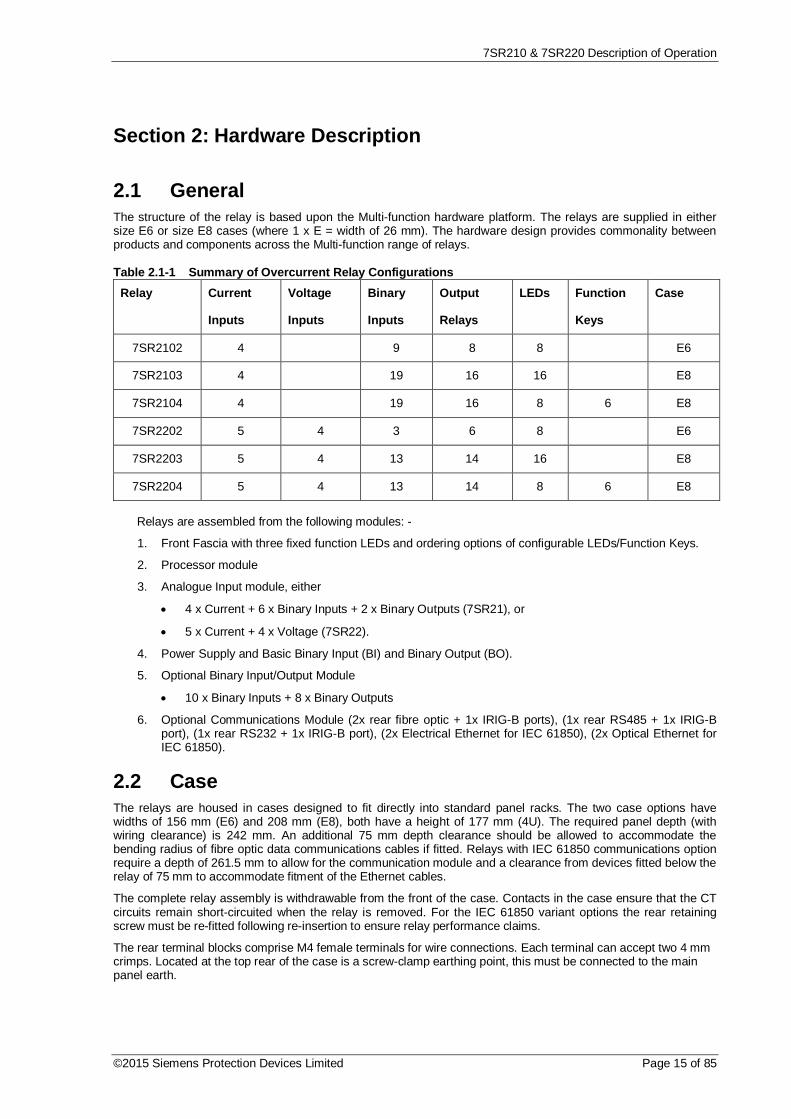
Figure 2.5-4 7SR22 with Function Keys & 3 + 8 LEDs in E8 Case and Ethernet Communication Interface
Relay Information
Above the LCD three labels are provided, these provide the following information: -
1) Product name and order code.
2) Nominal current rating, rated frequency, voltage rating, auxiliary dc supply rating, binary input supplyrating, configuration and serial number.
3) Blank label for user defined information.
A ‘template’ is available to allow users to create and print customised labels.
Liquid Crystal Display (LCD)
A 4-line by 20-character liquid crystal display indicates settings, instrumentation, fault data and controlcommands.
To conserve power the display backlighting is extinguished when no buttons are pressed for a user definedperiod. A setting within the “SYSTEM CONFIG” menu allows the timeout to be adjusted from 1 to 60 minutes and“Off” (backlight permanently on). Pressing any key will re-activate the display.
The LCD contrast can be adjusted using a flat blade screwdriver to turn the screw located below the contrastsymbol . Turning the screw clockwise increases the contrast, anti-clockwise reduces the contrast.
User defined indentifying text can be programmed into the relay using the System config/Relay Identifiersetting. The ‘Relay Identifier’ text is displayed on the LCD display at the top level of the menu structure and isused in communication with Reydisp to identify the relay. Pressing the Cancel button several times will alwaysreturn the user to this screen.
‘PROTECTION HEALTHY’ LED
This green LED is steadily illuminated to indicate that DC voltage has been applied to the relay power supply andthat the relay is operating correctly. If the internal relay watchdog detects an internal fault then this LED willcontinuously flash.

7SR210 & 7SR220 Description of Operation
©2015 Siemens Protection Devices Limited Page 19 of 85
‘PICKUP’ LED
This yellow LED is illuminated to indicate that a user selectable function(s) has picked up. The LED will self resetafter the initiating condition has been removed. The same LED can be assigned two different colours dependentupon whether a Pickup (PU) or Operate condition exists.
Functions are assigned to the PICKUP LED in the OUTPUT CONFIG>PICKUP CONFIG menu.
‘TRIP’ LED
This red LED is steadily illuminated to indicate that a user selectable function has operated to trip the circuitbreaker. Functions are assigned to the ‘Trip’ LED using the OUTPUT CONFIG>Trip Contacts setting.
Operation of the LED is latched and can be reset by either pressing the TEST/RESET button, energising asuitably programmed binary input, or, by sending an appropriate command over the data communicationschannel(s).
Indication LEDs (Numbered 1 to 8 or 1 to 16)Relays have either 8 or 16 user programmable Tri-colour (red, green or yellow) LED indicators, depending uponthe variant ordered. They are configured via the menu: -
Settings\ Output Config\LED Config menu orLED tab in Reydisp Evolution.
They can be designated as either: -Pick-Up (PU) LEDs (they respond upon the detection of a condition i.e. overcurrent detection), orOperation LEDs (they respond to the action of a condition i.e. CB trip operation).
Configuration options are: -Self Reset LEDs - automatically reset upon loss of initiating condition.PU Self Reset LEDs - automatically reset upon loss of initiating conditionGreen LEDs - illuminate greenRed LEDs - illuminate redYellow LEDs - illuminate yellow (when both red and green are selected)PU Green LEDs - illuminate green in response to the detection of a conditionPU Red LEDs - illuminate red in response to the detection of a condition
Colour selection is achieved by checking (ticking) the appropriate box i.e. red or green. To select yellow, checkboth red & green boxes.
Functions are assigned to the LEDs in the OUTPUT CONFIG>OUTPUT MATRIX menu.Each LED can be labelled by withdrawing the relay and inserting a label strip into the pocket behind the frontfascia. A ‘template’ is available to allow users to create and print customised legends.This can be found in: -
Reydisp Evolution\Help\Open Relay LED Template\Open RM LED Template
Each LED can be user programmed as hand or self –resetting. Hand reset LEDs can be reset by either pressingthe TEST/RESET button, energising a suitably programmed binary input, or, by sending an appropriatecommand over the data communications channel(s).The status of hand reset LEDs is maintained by a back up storage capacitor in the event of an interruption to thed.c. supply voltage.
Standard Pushbuttons
The relay is supplied as standard with five pushbuttons. The buttons are used to navigate the menu structure andcontrol relay functions. They are labelled: -
Increases a setting or moves up menu.
Decreases a setting or moves down menu.
TEST/RESET Moves right, can be used to reset selected functionality and for LED test (atrelay identifier screen).
ENTER Used to initiate and accept settings changes.
CANCEL Used to cancel settings changes and/or move up the menu structure by onelevel per press.
NOTE: All settings and configuration of LEDs, BI, BO and function keys can be accessed and set by the userusing these keys. Alternatively configuration/settings files can be loaded into the relay using ‘Reydisp Evolution’.

7SR210 & 7SR220 Description of Operation
Page 20 of 85 ©2015 Siemens Protection Devices Limited
Function Keys/ LEDs (Ordering Option)
Six additional programmable pushbuttons can be specified. These can be configured by the user to initiateselected functions from the Control menu (INPUT CONFIG > FUNCTION KEY MATRIX).
Each pushbutton has an associated LED. LEDs can be programmed as hand or self reset and can be illuminatedas green, yellow or red (OUTPUT CONFIG > LED CONFIG).
Function keys can be used with Quick Logic.

7SR210 & 7SR220 Description of Operation
©2015 Siemens Protection Devices Limited Page 21 of 85
2.6 Current InputsFour current inputs are provided in the 7SR21 relay and five inputs are provided in the 7SR22 relay. Currentinputs are located on the Analogue Input module. Terminals are available for both 1 A and 5 A inputs. Current issampled at 1600 Hz for both 50 Hz and 60 Hz system frequencies. Protection and monitoring functions of therelay use either the Fundamental Frequency RMS or the True RMS value of current appropriate to the individualfunction. The waveform recorder samples and displays current input waveforms at 1600 Hz.
NB: The Relay has a flat frequency response measuring harmonic currents up to and including the 50th Harmonicbut does not measure the content at the aliasing frequencies i.e. 800 Hz (16th harmonic) + 1600 Hz (32ndharmonic) + 2400 Hz (48th harmonic).
2.7 Voltage InputsFour voltage inputs are provided in the 7SR22 relay. Voltage inputs are located on the Analogue Input module.Voltage is sampled at 1600 Hz for both 50 Hz and 60 Hz system frequencies. Protection and monitoring functionsof the relay use fundamental frequency voltage measurement. The waveform recorder samples and displaysvoltage input waveforms at 1600 Hz.
2.8 Binary InputsThe binary inputs are operated from a suitably rated dc supply.
Relays are fitted with 3, 9, 13 or 19 binary inputs (BI). The user can assign any binary input to any of the availablefunctions (INPUT CONFIG > INPUT MATRIX).
The Power Supply module includes the relay basic I/O. The module includes 3 x BI and 6 x BO.
Non-directional (7SR21) relays have an additional 6 x BI on the analogue module.
Additional I/O modules may be fitted, these provide 10 x BI.
Pick-up (PU) and drop-off (DO) time delays are associated with each binary input. Where no pick-up time delayhas been applied the input may pick up due to induced ac voltage on the wiring connections (e.g. cross sitewiring). The default pick-up time of 20 ms provides ac immunity. Each input can be programmed independently.
Each input may be logically inverted to facilitate integration of the relay within the user scheme. When inverted therelay indicates that the BI is energised when no d.c. is applied. Inversion occurs before the PU & DO time delay,see fig. 2.8-1.
Each input may be mapped to any front Fascia indication LED and/or to any Binary output contact and can alsobe used with the internal user programmable logic. This allows the relay to provide panel indications and alarms.
The binary inputs are sampled every 5 ms.
Figure 2.8-1 Binary Input Logic

7SR210 & 7SR220 Description of Operation
Page 22 of 85 ©2015 Siemens Protection Devices Limited
2.9 Binary Outputs (Output Relays)Relays are fitted with 6, 8, 14 or 16 binary outputs (BO). All outputs are fully user configurable and can beprogrammed to operate from any or all of the available functions.
The Power Supply module includes the relay basic 6 x BO contacts configured as 1 x normally closed (NC), 2 xchange-over (CO) and 3 x normally open (NO) contacts.
Non-directional (7SR21) relays have two additional binary outputs providing 2 x NO contacts on the analoguemodule. Additional I/O modules may be fitted providing an extra 8 x NO contacts.
In the default mode of operation binary outputs are self reset and remain energised for a user configurableminimum time of up to 60 seconds. If required, outputs can be programmed to operate as ‘hand reset’ or ‘pulsed’.If the output relay is programmed to be ‘hand reset’ and ‘pulsed’ then the output will be ‘hand reset’ only.
The binary outputs can be used to operate the trip coils of the circuit breaker directly where the trip coil currentdoes not exceed the 'make and carry' contact rating. The circuit breaker auxiliary contacts or other in-seriesauxiliary device must be used to break the trip coil current.
Any BO can be assigned as a ‘Trip Contact’ in the OUTPUT CONFIG>TRIP CONFIG menu. Operation of a ‘TripContact’ will operate any LED or virtual assigned from the trip triggered feature in the same menu and will initiatethe fault record storage, actuate the ‘Trip Alert’ screen where enabled and CB Fail protection when enabled.
When the relay is withdrawn from the case all normally closed contacts will be open circuited. This should beconsidered in the design of the control and protection circuitry.
Notes on Pulsed Outputs
When operated, the output will reset after a user configurable time of up to 60 seconds regardless of the initiatingcondition.
Notes on Self Reset Outputs
Self reset operation has a minimum reset time of 100 ms.
With a failed breaker condition the relay may remain operated until current flow is interrupted by an upstreamdevice. When the current is removed the relay will then reset and attempt to interrupt trip coil current flowing viaits output contact. Where this current level is above the break rating of the output contact an auxiliary relay withheavy-duty contacts should be utilised in the primary system to avoid damage to the relay.
Notes on Hand Reset Outputs
Hand reset outputs can be reset by either pressing the TEST/RESET button, by energising a suitablyprogrammed binary input, or, by sending an appropriate command over the data communications channel(s).
On loss of the auxiliary supply hand-reset outputs will reset. When the auxiliary supply is re-established the binaryoutput will remain in the reset state unless the initiating condition is still present.
Event
Output 1
Min Operate Time
Hand Reset
BO 1 hand reset
S
RQ
OUTPUT CONFIG>OUTPUT MATRIX
(Or gates)
Logic signals,e.g. '51-1' Reset LEDs & Outputs (TEST/RESET key, Binary Input, Data Comms)
& &
&
1
1
Event
Output n
BO n hand reset
S
RQ
& &
&1
1
BO 1
BO n
OUTPUTCONFIG>BINARYOUTPUTCONFIG
OUTPUTCONFIG>BINARYOUTPUTCONFIG
Figure 2.9-1 Binary Output Logic

7SR210 & 7SR220 Description of Operation
©2015 Siemens Protection Devices Limited Page 23 of 85
2.10 Virtual Input/OutputsThe relays have 16 virtual input/outputs, these are internal logic states. Virtual I/O is assigned in the same way asphysical Binary Inputs and Binary Outputs. Virtual I/O is mapped from within the INPUT CONFIG > INPUTMATRIX and OUTPUT CONFIG > OUTPUT MATRIX menus.
The status of the virtual inputs and outputs is volatile i.e. not stored during power loss.
2.11 Self MonitoringThe relay incorporates a number of self-monitoring features. Each of these features can initiate a controlled resetrecovery sequence.
Supervision includes a power supply watchdog, code execution watchdog, memory checks by checksum andprocessor/ADC health checks. When all checks indicate the relay is operating correctly the ‘Protection Healthy’LED is illuminated.
If an internal failure is detected, a message will be displayed. The relay will reset in an attempt to rectify thefailure. This will result in de-energisation of any binary output mapped to ‘protection healthy’ and flashing of theprotection healthy LED. If a successful reset is achieved by the relay the LED and output contact will revert backto normal operational mode, and the relay will restart, therefore ensuring the circuit is protected for the maximumtime.
A Start-up Counter Meter is provided to display the number of start-ups the relay has performed. Once thenumber of start-ups has exceeded a set number, an Alarm output can be given.
Figure 2.11-1 Start-up Counter MeterReset of the counter can be done from the meter or via a binary input or a command.
Various types of start-up are monitored by the relay:1. power-on starts (auxiliary supply initiation)2. expected starts (user initiated via comms, language changes, custom protection curve etc.)3. unexpected starts (caused by the relay watchdog)
Any combination of these can be selected for the start-up count. This is done in the MAINTENANCEMENU>START COUNT menu using the Start Up Types setting. All the start-up types selected will be added tothe overall start-up count.
The number of restarts before the alarm output is raised is set in the MAINTENANCE MENU>START COUNTmenu using the Start Up Count Target setting.
When the number of relay start-ups reaches the target value an output is raised, OUTPUT MATRIX>Start UpCount Alarm, which can be programmed to any combination of binary outputs, LED’s or virtual outputs.
2.11.1 Protection Healthy/DefectiveWhen the relay has an auxiliary DC supply and it has successfully passed its self-checking procedure then thefront facia Protection Healthy LED is turned on.
A normally open contact can be used to signal protection healthy. When the relay has DC supply and it hassuccessfully passed its self-checking procedure then the Protection Healthy contacts are made.
A changeover or normally closed contact can be mapped via the binary output matrix to provide an externalprotection defective signal. With the ‘Protection Healthy’ this contact is open. When the auxiliary DC supply is notapplied to the relay or a problem is detected within the relay then this output contact closes to provide externalindication.
An alarm can be provided if the relay is withdrawn from the case. A contact is provided in the case at positions25-26 of the PSU module, this contact closes when the relay is withdrawn.

7SR210 & 7SR220 Description of Operation
Page 24 of 85 ©2015 Siemens Protection Devices Limited
Section 3: Protection Functions
3.1 Current Protection: Phase Overcurrent (67, 51, 50)All phase overcurrent elements can be set to measure either fundamental frequency RMS or True RMS currenti.e.
True RMS current: - 50 Measurement = RMS
51 Measurement = RMS
Fundamental Frequency RMS current: - 50 Measurement = Fundamental
51 Measurement = Fundamental
3.1.1 Directional Control of Overcurrent Protection (67) – 7SR22The directional element produces forward and reverse outputs for use with overcurrent elements. These outputscan then be mapped as controls to each shaped and instantaneous over-current element.
If a protection element is set as non-directional then it will operate independently of the output of the directionaldetector. However, if a protection element is programmed for forward directional mode then operation will occuronly for a fault lying within the forward operate zone. Conversely, if a protection element is programmed forreverse directional mode then operation will occur only for a fault lying within the reverse operate zone. Typicallythe forward direction is defined as being ‘away’ from the busbar or towards the protected zone.
The Characteristic angle is the phase angle by which the polarising voltage must be adjusted such that thedirectional detector gives maximum sensitivity in the forward operate zone when the current is in phase with it.The reverse operate zone is the mirror image of the forward zone.
Voltage polarisation is achieved for the phase-fault elements using the quadrature voltage i.e. at unity powerfactor I leads V by 90°. Each phase current is compared to the voltage between the other two phases: -
IL1 ~ V23 IL2 ~ V31 IL3 ~ V12
The characteristic angle can be user programmed to any angle between -95° and +95° using the 67 Char Anglesetting. The voltage is the reference phasor (Vref) and the 67 Char Angle setting is added to this to adjust theforward and reverse zones.
The centre of the forward zone is set by (Vref Angle + 67 Char Angle) and should be set to correspond with IfaultAngle for maximum sensitivity i.e.
For fault current of -60° (I lagging V by 60°) a 67 Char Angle of +30° is required for maximum sensitivity(i.e. due to quadrature connection 90° - 60° = 30°)
OR
For fault current of -45° (I lagging V by 45°) a 67 Char Angle of +45° is required for maximum sensitivity(i.e. due to quadrature connection 90° - 45° = 45°).
Two-out-of-three Gate
When the 67 2-Out-Of-3 Logic setting is set to Enabled, the directional elements will only operate for themajority direction, e.g. if IL1 and IL3 are detected as forward flowing currents and IL2 is detected as reverse currentflow, phases L1 and L3 will operate forwards, while phase L2 will be inhibited.

7SR210 & 7SR220 Description of Operation
©2015 Siemens Protection Devices Limited Page 25 of 85
Minimum Polarising Voltage
The 67 Minimum Voltage setting defines the minimum polarising voltage level. Where the measured polarisingvoltage is below this level no directional output is given and operation of protection elements set as directional willbe inhibited. This prevents mal-operation under fuse failure/MCB tripped conditions where noise voltages can bepresent.
Figure 3.1.1-1 Logic Diagram: Directional Overcurrent Element (67)

7SR210 & 7SR220 Description of Operation
Page 26 of 85 ©2015 Siemens Protection Devices Limited
3.1.2 Instantaneous Overcurrent Protection (50)Two instantaneous overcurrent elements are provided in the 7SR21 relay. Four elements are provided in the7SR22 e.g. giving the option of using two elements set to forward and two to reverse.
Each instantaneous element (50-n) has independent settings. 50-n Setting for pick-up current and 50-n Delayfollower time delay. The instantaneous elements have transient free operation.
Where directional elements are present the direction of operation can be set using 50-n Dir. Control setting.Directional logic is provided independently for each 50-n element.
Operation of the instantaneous overcurrent elements can be inhibited from:
Inhibit 50-n A binary input, virtual input, function key or remote data Comms.
79 P/F Inst Trips: 50-n When ‘delayed’ trips only are allowed in the auto-reclose sequence(79 P/F Prot’n Trip n = Delayed).
50-n Inrush Action: Inhibit Operation of the inrush current detector function.
50-n VTS Action: Inhibit Operation of the VT Supervision function (7SR22).
Figure 3.1.2-1 Logic Diagram: Instantaneous Over-current Element

7SR210 & 7SR220 Description of Operation
©2015 Siemens Protection Devices Limited Page 27 of 85
3.1.3 Time Delayed Overcurrent Protection (51)Two time delayed overcurrent elements are provided in the 7SR21 relay. Four elements are provided in the7SR22 relay e.g. giving the option of using two elements set to forward and two to reverse.
51-n Setting sets the pick-up current level. Where the voltage controlled overcurrent function (51VCO) is used(7SR22 relays only) a multiplier is applied to this setting where the voltage drops below the setting VCO Setting,see section 3.2.
A number of shaped characteristics are provided. An inverse definite minimum time (IDMT) characteristic isselected from IEC and ANSI curves using 51-n Char. A time multiplier is applied to the characteristic curves usingthe 51-n Time Mult setting. Alternatively, a definite time lag delay (DTL) can be chosen using 51-n Char. WhenDelay (DTL) is selected the time multiplier is not applied and the 51-n Delay (DTL) setting is used instead.
The 51-n Reset setting can apply a definite time delayed reset, or when configured as an ANSI characteristic anANSI (DECAYING) reset. If ANSI (DECAYING) reset is selected for an IEC characteristic, the reset will beinstantaneous. The reset mode is significant where the characteristic has reset before issuing a trip output – see‘Applications Guide’.
A minimum operate time for the characteristic can be set using 51-n Min. Operate Time setting.
A fixed additional operate time can be added to the characteristic using 51-n Follower DTL setting.
Where directional elements are present the direction of operation can be set using 51-n Dir. Control setting.Directional logic is provided independently for each 51-n element.
Operation of the time delayed overcurrent elements can be inhibited from: -
Inhibit 51-n A binary input, virtual input, function key or remote data Comms
79 P/F Inst Trips: 51-n When ‘delayed’ trips only are allowed in the auto-reclose sequence(79 P/F Prot’n Trip n = Delayed).
51c Activation of the cold load settings (see section 3.7).
51-n Inrush Action: Inhibit Operation of the inrush current detector function.
51-n VTSAction: Inhibit Operation of the VT Supervision function (7SR22).

7SR210 & 7SR220 Description of Operation
Page 28 of 85 ©2015 Siemens Protection Devices Limited
1
1General Pickup
51-n
If directional elements are not present this block isomitted and all 'Lx Dir En' signals are set TRUE.
51-n Setting
51-n Charact
51-n Time Mult
51-n Delay (DTL)
51-n Reset
c
Forward
Reverse
51-n Dir Control
Non-Dir
1&
&
1&
&
1&
&
51-n Follower DTL
L1 Dir En
L2 Dir En
L3 Dir En
L1 Dir En
L2 Dir En
L3 Dir En
IL1 Fwd
IL1 Rev
IL2 Fwd
IL2 Rev
IL3 Fwd
IL3 Rev
&
&
&
1
1
1
Non Dir
51-n VTS Action
Off
Inhibit
60VTS
&
51-n Min. Operate Time
&
IL1
IL2
IL3
50/51Measurement
&
See Voltage ControlledOvercurrent (51V)
L1 81HBL2
51c
51-n InrushAction
Off
Inhibit
&
L3L2L1
L2 81HBL2
L3 81HBL2
&
&
&
&
&
c Pickup
trip
c Pickup
trip
c Pickup
trip
Inhibit 51-n
51-n Element
Enabled
Disabled
&79 P/F Inst Trips= 51-n
79 P/F Prot’n Trip n= Delayed
AUTORECLOSE
NB: For a comprehensivelist of input & output signalssee Data Comms Definitions
Inhibit 51-n
51-n
General Pickup
Figure 3.1.3-1 Logic Diagram: Time Delayed Overcurrent Element

7SR210 & 7SR220 Description of Operation
©2015 Siemens Protection Devices Limited Page 29 of 85
3.2 Current Protection: Voltage Controlled Overcurrent (51V)– 7SR22
Voltage controlled overcurrent is available in the 7SR22 relay.
Each shaped overcurrent element 51-n Setting can be independently controlled by the level of measured(control) input voltage.
For applied voltages above VCO Setting the 51-n element operates in accordance with its normal current setting(see 3.1.3). For input Ph-Ph control voltages below VCO Setting a multiplier (51-n Multiplier) is applied toreduce the 51-n pickup current setting.
51-n Multiplier is applied to each phase independently when its control phase-phase voltage falls below VCOSetting. The voltage levels used for each phase over-current element are shown in the table below. Relays with aPh-N connection automatically calculate the correct Ph-Ph control voltage.
Current Element Control VoltageIL1 V12
IL2 V23
IL3 V31
The Voltage Controlled Overcurrent function (51V) can be inhibited from: -
VCO VTSAction: Inhibit Operation of the VT Supervision function.
VL1
51V Setting
c
&
51V Element
Enabled
Disabled
<
<
<
VL2
VL3
51V VTS Action
Off
Inhibit
SeeDelayedOvercurrent(51-n)
VT Fail
&
51-n Multiplier
c
V12
V31
V23
cx IL1 51-n Setting
cx IL2 51-n Setting
cx IL3 51-n Setting
L3
L2
L1
Figure 3.2-1 Logic Diagram: Voltage Controlled Overcurrent Protection

7SR210 & 7SR220 Description of Operation
Page 30 of 85 ©2015 Siemens Protection Devices Limited
3.3 Current Protection: Derived Earth Fault (67N, 51N, 50N)The earth current is derived by calculating the sum of the measured line currents. The elements measure thefundamental frequency RMS current.
3.3.1 Directional Control of Derived Earth Fault Protection (67N) – 7SR22The directional element produces forward and reverse outputs for use with derived earth fault elements. Theseoutputs can be mapped as controls to each shaped and instantaneous element.
If a protection element is set as non-directional then it will operate independently of the output of the directionaldetector. However, if a protection element is programmed for forward directional mode then operation will occuronly for a fault lying within the forward operate zone. Conversely, if a protection element is programmed forreverse directional mode then operation will occur only for a fault lying within the reverse operate zone. Typicallythe forward direction is defined as being ‘away’ from the busbar or towards the protected zone.
The Characteristic angle is the phase angle by which the polarising voltage must be adjusted such that thedirectional detector gives maximum sensitivity in the forward operate zone when the current is in phase with it.The reverse operate zone is the mirror image of the forward zone.
The derived directional earth fault elements can use either zero phase sequence (ZPS) or negative phasesequence (NPS) polarising. This is selected using the 67N Polarising Quantity setting. Whenever a zero-sequence voltage is available (a five-limb VT that can provide a zero sequence path or an open-delta VTconnection) the earth-fault element can use zero-sequence voltage and current for polarisation. If zero-sequencepolarising voltage is not available e.g. when a two phase (phase to phase) connected VT is installed, thennegative-sequence voltage and negative-sequence currents must be used. The type of VT connection is specifiedby Voltage Config (CT/VT CONFIG menu). Settings advice is given in the Applications Guide.
Voltage polarisation is achieved for the earth-fault elements by comparison of the appropriate current with itsequivalent voltage: -
67N Polarising Quantity: ZPS I0 ~ V0
67N Polarising Quantity: NPS I2 ~ V2
The characteristic angle can be user programmed to any angle between -95° and +95° using the 67N Char Anglesetting. The voltage is the reference phasor (Vref) and the 67N Char Angle setting is added to this to adjust theforward and reverse zones.
The centre of the forward zone is set by (Vref Angle + 67N Char Angle) and should be set to correspond with IfaultAngle for maximum sensitivity e.g.
For fault current of -15° (I lagging V by 15°) a 67N Char Angle of -15° is required for maximum sensitivity
OR
For fault current of -45° (I lagging V by 45°) a 67 Char Angle of -45° is required for maximum sensitivity.

7SR210 & 7SR220 Description of Operation
©2015 Siemens Protection Devices Limited Page 31 of 85
Minimum Polarising Voltage
The 67N Minimum Voltage setting defines the minimum polarising voltage level. Where the measured polarisingvoltage is below this level no directional output is given and operation of protection elements set as directional willbe inhibited. This prevents mal-operation under fuse failure/MCB tripped conditions where noise voltages can bepresent.
Figure 3.3.1-1 Logic Diagram: Derived Directional Earth Fault Element
3.3.2 Instantaneous Derived Earth Fault Protection (50N)Two instantaneous derived earth fault elements are provided in the 7SR21 relay. Four elements are provided inthe 7SR22 relay e.g. giving the option of using two elements set to forward and two to reverse.
Each instantaneous element has independent settings for pick-up current 50N-n Setting and a follower timedelay 50N-n Delay. The instantaneous elements have transient free operation.
Where directional elements are present the direction of operation can be set using 50N-n Dir. Control setting.Directional logic is provided independently for each 50-n element.
Operation of the instantaneous earth fault elements can be inhibited from: -
Inhibit 50N-n A binary input, virtual input, function key or remote data Comms.
79 E/F Inst Trips: 50N-n When ‘delayed’ trips only are allowed in the auto-reclose sequence(79 E/F Prot’n Trip n = Delayed).
50N-n VTSAction: Inhibit Operation of the VT Supervision function (7SR22).
50N-n Inrush Action: Inhibit Operation of the current inrush detector function.

7SR210 & 7SR220 Description of Operation
Page 32 of 85 ©2015 Siemens Protection Devices Limited
50N-n>c
50N-nSetting
If directional elements are not present this block isomitted and the '50N-n Dir En' signal is set TRUE.
Forward
Reverse
50N-n Dir
Non-Dir
1&
&
50N-n Dir En
67N Fwd
67N Rev
50N-n Delay
50N-n VTS Action
Off
Non Dir
Inhibit
VT Fail
& &
&
1
IL1
IL2
IL3
IN
Inhibit 50N-n
50N-n Element
Enabled
Disabled
81HBL2
50N-n InrushAction
Off
Inhibit&
50N-n Dir En
General Pickup
&79 P/F Inst Trips= 50N-n
79 P/F Prot’n Trip n= Delayed
AUTORECLOSE
Inhibit 50N-n
General Pickup
50N-n
&
Figure 3.3.2-1 Logic Diagram: Derived Instantaneous Earth Fault Element
3.3.3 Time Delayed Derived Earth Fault Protection (51N)Two time-delayed derived earth fault elements are provided in the 7SR21 relay. Four elements are provided in the7SR22 relay e.g. giving the option of using two elements set to forward and two to reverse.
51N-n Setting sets the pick-up current level.
A number of shaped characteristics are provided. An inverse definite minimum time (IDMT) characteristic isselected from IEC and ANSI curves using 51N-n Char. A time multiplier is applied to the characteristic curvesusing the 51N-n Time Mult setting. Alternatively, a definite time lag delay (DTL) can be chosen using 51N-nChar. When Delay (DTL) is selected the time multiplier is not applied and the 51N-n Delay (DTL) setting is usedinstead.
The 51N-n Reset setting can apply a definite time delayed reset, or when configured as an ANSI characteristican ANSI (DECAYING) reset. If ANSI (DECAYING) reset is selected for an IEC characteristic, the reset will beinstantaneous. The reset mode is significant where the characteristic has reset before issuing a trip output – see‘Applications Guide’.
A minimum operate time for the characteristic can be set using the 51N-n Min. Operate Time setting.
A fixed additional operate time can be added to the characteristic using the 51N-n Follower DTL setting.
Where directional elements are present the direction of operation can be set using 51N-n Dir. Control setting.Directional logic is provided independently for each 51N-n element.

7SR210 & 7SR220 Description of Operation
©2015 Siemens Protection Devices Limited Page 33 of 85
Operation of the time delayed earth fault elements can be inhibited from: -
Inhibit 51N-n A binary or virtual input, function key or remote data Comms.
79 E/F Inst Trips: 51N-n When ‘delayed’ trips only are allowed in the auto-reclose sequence(79 E/F Prot’n Trip n = Delayed).
51N-n Inrush Action: Inhibit Operation of the current inrush detector function.
51N-n VTSAction: Inhibit Operation of the VT Supervision function (7SR22).
Figure 3.3.3-1 Logic Diagram: Derived Time Delayed Earth Fault Protection

7SR210 & 7SR220 Description of Operation
Page 34 of 85 ©2015 Siemens Protection Devices Limited
3.4 Current Protection: Measured Earth Fault (67G, 51G, 50G)The earth current is measured directly via a dedicated current analogue input.
All phase overcurrent elements can be set to measure either fundamental frequency RMS or True RMS currenti.e.
True RMS current: - 50 Measurement = RMS
51 Measurement = RMS
Fundamental Frequency RMS current: - 50 Measurement = Fundamental
51 Measurement = Fundamental
3.4.1 Directional Control of Measured Earth Fault Protection (67G) – 7SR22The directional element produces forward and reverse outputs for use with measured earth fault elements. Theseoutputs can be mapped as controls to each shaped and instantaneous element.
If a protection element is set as non-directional then it will operate independently of the output of the directionaldetector. However, if a protection element is programmed for forward directional mode then operation will occuronly for a fault lying within the forward operate zone. Conversely, if a protection element is programmed forreverse directional mode then operation will occur only for a fault lying within the reverse operate zone. Typicallythe forward direction is defined as being ‘away’ from the busbar or towards the protected zone.
The Characteristic angle is the phase angle by which the polarising voltage must be adjusted such that thedirectional detector gives maximum sensitivity in the forward operate zone when the current is in phase with it.The reverse operate zone is the mirror image of the forward zone.
The measured directional earth fault elements use zero phase sequence (ZPS) polarising.
Voltage polarisation is achieved for the earth-fault elements by comparison of the appropriate current with itsequivalent voltage: -
I0 ~ V0
The characteristic angle can be user programmed to any angle between -95° and +95° using the 67G CharAngle setting. The voltage is the reference phasor (Vref) and the 67G Char Angle setting is added to this to adjustthe forward and reverse zones.
The centre of the forward zone is set by (Vref Angle + 67G Char Angle) and should be set to correspond with IfaultAngle for maximum sensitivity e.g.
For fault current of -15° (I lagging V by 15°) a 67G Char Angle of -15° is required for maximumsensitivity, OR
For fault current of -45° (I lagging V by 45°) a 67G Char Angle of -45° is required for maximumsensitivity.
Minimum Polarising Voltage
The 67G Minimum Voltage setting defines the minimum polarising voltage level. Where the measured polarisingvoltage is below this level no directional output is given and. Operation of protection elements set as directionalwill be inhibited. This prevents mal-operation under fuse failure/MCB tripped conditions where noise voltages canbe present.
Figure 3.4.1-1 Logic Diagram: Measured Directional Earth Fault Protection

7SR210 & 7SR220 Description of Operation
©2015 Siemens Protection Devices Limited Page 35 of 85
3.4.2 Instantaneous Measured Earth Fault Protection (50G)Two instantaneous measured earth fault elements are provided in the 7SR21 relay. Four elements are provided inthe 7SR22 relay e.g. giving the option of using two elements set to forward and two to reverse.
Each instantaneous element has independent settings for pick-up current 50G-n Setting and a follower timedelay 50G-n Delay. The instantaneous elements have transient free operation.
Where directional elements are present the direction of operation can be set using 50G-n Dir. Control setting.Directional logic is provided independently for each 50G-n element.
Operation of the instantaneous measured earth fault elements can be inhibited from: -
Inhibit 50G-n A binary or virtual input, function key or remote data Comms.
79 E/F Inst Trips: 50G-n When ‘delayed’ trips only are allowed in the auto-reclose sequence(79 E/F Prot’n Trip n = Delayed).
50G-n Inrush Action: Inhibit Operation of the current inrush detector function.
50G-n VTSAction: Inhibit Operation of the VT Supervision function (7SR22).
Figure 3.4.2-1 Logic Diagram: Measured Instantaneous Earth-fault Element

7SR210 & 7SR220 Description of Operation
Page 36 of 85 ©2015 Siemens Protection Devices Limited
3.4.3 Time Delayed Measured Earth Fault Protection (51G)Two time delayed measured earth fault elements are provided in the 7SR21 relay. Four elements are provided inthe 7SR22 relay e.g. giving the option of using two elements set to forward and two to reverse.
51G-n Setting sets the pick-up current level.
A number of shaped characteristics are provided. An inverse definite minimum time (IDMT) characteristic isselected from IEC and ANSI curves using 51G-n Char. A time multiplier is applied to the characteristic curvesusing the 51G-n Time Mult setting. Alternatively, a definite time lag (DTL) can be chosen using 51G-n Char.When DTL is selected the time multiplier is not applied and the 51G-n Delay (DTL) setting is used instead.
The 51G-n Reset setting can apply a definite time delayed reset, or when configured as an ANSI characteristican ANSI (DECAYING) reset. If ANSI (DECAYING) reset is selected for an IEC characteristic, the reset will beinstantaneous. The reset mode is significant where the characteristic has reset before issuing a trip output – see‘Applications Guide’.
A minimum operate time for the characteristic can be set using 51G-n Min. Operate Time setting.
A fixed additional operate time can be added to the characteristic using 51G-n Follower DTL setting.
Where directional elements are present the direction of operation can be set using 51G-n Dir. Control setting.Directional logic is provided independently for each 51G-n element.
Operation of the time delayed measured earth fault elements can be inhibited from:
Inhibit 51G-n A binary or virtual input, function key or remote data Comms.
79 E/F Inst Trips: 51G-n When ‘delayed’ trips only are allowed in the auto-reclose sequence(79 E/F Prot’n Trip n = Delayed).
51G-n Inrush Action: Inhibit Operation of the inrush current detector function.
51G-n VTSAction: Inhibit Operation of the VT Supervision function (7SR22).
Figure 3.4.3-1 Logic Diagram: Measured Time Delayed Earth Fault Element (51G)

7SR210 & 7SR220 Description of Operation
©2015 Siemens Protection Devices Limited Page 37 of 85
3.5 Current Protection: Sensitive Earth Fault (67SEF, 51SEF,50SEF)
Current for the Sensitive Earth Fault (SEF) elements is measured directly via a dedicated current analogue input.SEF elements measure the fundamental frequency RMS current.
3.5.1 Directional Control of Sensitive Earth Fault Protection (67SEF) – 7SR22The directional element produces forward and reverse outputs for use with SEF elements. These outputs can bemapped as controls to each shaped and instantaneous element.
If a protection element is set as non-directional then it will operate independently of the output of the directionaldetector. However, if a protection element is programmed for forward directional mode then operation will occuronly for a fault lying within the forward operate zone. Conversely, if a protection element is programmed forreverse directional mode then operation will occur only for a fault lying within the reverse operate zone. Typicallythe forward direction is defined as being ‘away’ from the busbar or towards the protected zone.
The Characteristic angle is the phase angle by which the polarising voltage must be adjusted such that thedirectional detector gives maximum sensitivity in the forward operate zone when the current is in phase with it.The reverse operate zone is the mirror image of the forward zone.
The directional sensitive earth fault elements use zero phase sequence (ZPS) polarising.
Voltage polarisation is achieved for the earth-fault elements by comparison of the appropriate current with itsequivalent voltage: -
I0 ~ V0
The characteristic angle can be user programmed to any angle between -95° and +95° using the 67SEF CharAngle setting. The voltage is the reference phasor (Vref) and the 67SEF Char Angle setting is added to this toadjust the forward and reverse zones.
The centre of the forward zone is set by (Vref Angle + 67SEF Char Angle) and should be set to correspond withIfault Angle for maximum sensitivity i.e.
For fault current of -15° (I lagging V by 15°) a 67SEF Char Angle of -15° is required for maximumsensitivity
OR
For fault current of -45° (I lagging V by 45°) a 67SEF Char Angle of -45° is required for maximumsensitivity.
Minimum Polarising Voltage
The 67SEF Minimum Voltage setting defines the minimum polarising voltage level. Where the measuredpolarising voltage is below this level no directional output is given and. Operation of protection elements set asdirectional will be inhibited. This prevents mal-operation under fuse failure/MCB tripped conditions where noisevoltages can be present.
Figure 3.5.1-1 Logic Diagram: SEF Directional Element (67SEF)

7SR210 & 7SR220 Description of Operation
Page 38 of 85 ©2015 Siemens Protection Devices Limited
3.5.2 Instantaneous Sensitive Earth Fault Protection (50SEF)Two instantaneous SEF elements are provided in the 7SR21 relay. Four elements are provided in the 7SR22relay e.g. giving the option of using two elements set to forward and two to reverse.
Each instantaneous element has independent settings for pick-up current 50SEF-n Setting and a follower timedelay 50SEF-n Delay. The instantaneous elements have transient free operation.
Where directional elements are present the direction of operation can be set using 50SEF-n Dir. Control setting.Directional logic is provided independently for each 50SEF-n element.
Operation of the instantaneous earth fault elements can be inhibited from: -
Inhibit 50SEF-n A binary or virtual input, function key or remote data Comms
79 SEF Inst Trips: 50SEF-n When ‘delayed’ trips only are allowed in the auto-reclose sequence(79 SEF Prot’n Trip n = Delayed).
50SEF-n VTSAction: Inhibit Operation of the VT Supervision function (7SR22).
50SEF-n>c
50SEF-n Setting
If directional elements are not present this block isomitted and the '50SEF-n Dir En' signal is set TRUE.
Forward
Reverse
50SEF-n Dir.Control
Non-Dir
1&
&
50SEF-n Dir En
67SEF Fwd
67SEF Rev
50SEF-n Delay
50SEF-n VTS Action
Off
Non-Dir
Inhibit
VT Fail
& &
&
1
I4 (7SR21)I5 (7SR22)
(ISEF)
General Pickup
Inhibit 50SEF-n
&
50SEF-n Element
Enabled
Disabled
50SEF-n Dir En
&79 P/F Inst Trips= 50SEF-n
79 P/F Prot’n Trip n= Delayed
AUTORECLOSE Inhibit 50SEF-n General Pickup
50SEF-n
Figure 3.5.2-1 Logic Diagram: SEF Instantaneous Element

7SR210 & 7SR220 Description of Operation
©2015 Siemens Protection Devices Limited Page 39 of 85
3.5.3 Time Delayed Sensitive Earth Fault Protection (51SEF)Two time delayed sensitive earth fault elements are provided in the 7SR21 relay. Four elements are provided inthe 7SR22 relay. e.g. giving the option of using two elements set to forward and two to reverse.
51SEF-n Setting sets the pick-up current level.
A number of shaped characteristics are provided. An inverse definite minimum time (IDMT) characteristic isselected from IEC and ANSI curves using 51SEF-n Char. A time multiplier is applied to the characteristic curvesusing the 51SEF-n Time Mult setting. Alternatively, a definite time lag (DTL) can be chosen using 51SEF-n Char.When DTL is selected the time multiplier is not applied and the 51SEF-n Delay (DTL) setting is used instead.
The 51SEF-n Reset setting can apply a definite time delayed reset, or when configured as an ANSIcharacteristic an ANSI (DECAYING) reset. If ANSI (DECAYING) reset is selected for an IEC characteristic, thereset will be instantaneous. The reset mode is significant where the characteristic has reset before issuing a tripoutput – see ‘Applications Guide’.
A minimum operate time for the characteristic can be set using 51SEF-n Min. Operate Time setting.
A fixed additional operate time can be added to the characteristic using 51SEF-n Follower DTL setting.
Where directional elements are present the direction of operation can be set using 51SEF-n Dir. Control setting.Directional logic is provided independently for each 51SEF-n element.
Operation of the time delayed earth fault elements can be inhibited from: -
Inhibit 51SEF-n A binary or virtual input, function key or remote data Comms
79 SEF Inst Trips: 51SEF-n When ‘delayed’ trips only are allowed in the auto-reclose sequence(79 SEF Prot’n Trip n = Delayed).
51SEF-n VTSAction: Inhibit Operation of the VT Supervision function (7SR22).
Figure 3.5.2-2 Logic Diagram: SEF Time Delayed Element (51SEF)

7SR210 & 7SR220 Description of Operation
Page 40 of 85 ©2015 Siemens Protection Devices Limited
3.6 Current Protection: High Impedance Restricted EarthFault (64H)
One high impedance Restricted Earth Fault (REF) element is provided.
The relay utilises fundamental current measurement values for this function.
The single phase current input is derived from the residual output of line/neutral CTs connected in parallel. Anexternal stabilising resistor must be connected in series with this input to ensure that this element provides a highimpedance path.
64H Current Setting sets the pick-up current level. An output is given after elapse of the 64H Delay setting.
External components – a series stabilising resistor and a non-linear resistor – are used with this function. See‘Applications Guide’ for advice in specifying suitable component values.
Operation of the high impedance element can be inhibited from: -
Inhibit 64H A binary or virtual input, function key or remote data Comms
Figure 3.6-1 Logic Diagram: High Impedance REF (64H)

7SR210 & 7SR220 Description of Operation
©2015 Siemens Protection Devices Limited Page 41 of 85
3.7 Current Protection: Cold Load (51c)
The setting of each shaped overcurrent element (51-n) can be inhibited and alternative ‘cold load’ settings (51c-n)can be applied for a period following circuit switch in.
The Cold Load settings are applied after the circuit breaker has been open for longer than the Pick-Up Timesetting.
Following circuit breaker closure the ‘cold load’ overcurrent settings will revert to those defined in the PhaseOvercurrent menu (51-n) after either elapse of the Drop-Off Time setting or when the measured current fallsbelow the Reduced Current Level setting for a time in excess of Reduced Current Time setting.
During cold load settings conditions any directional settings applied in the Phase Overcurrent menu are stillapplicable.
A CB ‘Don’t Believe It’ (DBI) condition is not acted on, causing the element to remain operating in accordancewith the relevant 51-n settings. Where the Reduced Current setting is set to OFF reversion to 51-n settings willonly occur at the end of the Drop-Off Time. If any element is picked up on expiry of Drop-Off Time the relay willissue a trip (and lockout if a recloser is present).
If the circuit breaker is re-opened before expiry of the Drop-Off Time the drop-off timer is held but not reset.Resetting the timer for each trip could result in damaging levels of current flowing for a prolonged period during arapid sequence of trips/closes.
Cold load trips use the same binary output(s) as the associated 51-n element.
Figure 3.7-1 Logic Diagram: Cold Load Settings (51c)

7SR210 & 7SR220 Description of Operation
Page 42 of 85 ©2015 Siemens Protection Devices Limited
3.8 Current Protection: Negative Phase SequenceOvercurrent (46NPS)
The negative sequence phase (NPS) component of current (I2) is derived from the three phase currents. It is ameasure of the quantity of unbalanced current in the system.
Two NPS current elements are provided – 46IT and 46DT.
The 46IT element can be configured to be either definite time lag (DTL) or inverse definite minimum time (IDMT),
46IT Setting sets the pick-up current level for the element.
A number of shaped characteristics are provided. An inverse definite minimum time (IDMT) characteristic isselected from IEC and ANSI curves using 46IT Char. A time multiplier is applied to the characteristic curves usingthe 46IT Time Mult setting. Alternatively, a definite time lag delay (DTL) can be chosen using 46ITChar. WhenDelay (DTL) is selected the time multiplier is not applied and the 46IT Delay (DTL) setting is used instead.
The 46IT Reset setting can apply a, definite time delayed or ANSI (DECAYING) reset.
The 46DT element has a DTL characteristic. 46DT Setting sets the pick-up current and 46DT Delay the followertime delay.
Operation of the negative phase sequence overcurrent elements can be inhibited from:
Inhibit 46IT A binary or virtual input, function key or remote data Comms
Inhibit 46DT A binary or virtual input, function key or remote data Comms
Figure 3.8-1 Logic Diagram: Negative Phase Sequence Overcurrent (46NPS)

7SR210 & 7SR220 Description of Operation
©2015 Siemens Protection Devices Limited Page 43 of 85
3.9 Current Protection: Under-Current (37, 37G & 37SEF)
Two under-current elements are provided for each 37, 37G & 37SEF protection function.
Each phase has an independent level detector and current-timing element. 37-n Setting sets the pick-up current.An output is given after elapse of the 37-n Delay setting.
Operation of the under-current elements can be inhibited from: -
Inhibit 37-n A binary or virtual input, function key or remote data Comms
Figure 3.9-1 Logic Diagram: Undercurrent Detector (37, 37G & 37SEF)
3.10 Current Protection: Under-Current Guarded (37)
A level detector 37-n U/I Guard Setting sets the pick-up current.
Figure 3.10-1 Logic Diagram: Undercurrent Guarded Detector (37)

7SR210 & 7SR220 Description of Operation
Page 44 of 85 ©2015 Siemens Protection Devices Limited
3.11 Current Protection: Thermal Overload (49)
The relay provides a thermal overload suitable for the protection of static plant. Phase segregated elements areprovided. The temperature of the protected equipment is not measured directly. Instead, thermal overloadconditions are calculated using the measure True RMS current.
Should the current rise above the 49 Overload Setting for a defined time an output signal will be initiated.
Operate Time (t): -
Where
T = Time in minutes
t = 49 Time Constant setting (minutes)
In = Log Natural
I = measured current
IP = Previous steady state current level
k = Constant
IB = Basic current, typically the same as In
k.IB = 49 Overload Setting (Iq)
Additionally, an alarm can be given if the thermal state of the system exceeds a specified percentage of theprotected equipment’s thermal capacity 49 Capacity Alarm setting.
For the heating curve: -
Where: q = thermal state at time t
I = measured thermal current
Iq = 49 Overload setting (or k.IB)
The final steady state thermal condition can be predicted for any steady state value of input current where t >t,
Where: qF = final thermal state before disconnection of device
49 Overload Setting Iq is expressed as a multiple of the relay nominal current and is equivalent to the factor k.IBas defined in the IEC255-8 thermal operating characteristics. It is the value of current above which 100% ofthermal capacity will be reached after a period of time and it is therefore normally set slightly above the full loadcurrent of the protected device.
The thermal state may be reset from the fascia or externally via a binary input.
Thermal overload protection can be inhibited from: -
Inhibit 49 A binary or virtual input, function key or remote data Comms.
( ) þýü
îíì
´--
´= 2B
2
2P
2
IkIIIlnt t
100%)e(1II
θ τt
2θ
2
´-×=-
100%II
θ 2θ
2
F ´=

7SR210 & 7SR220 Description of Operation
©2015 Siemens Protection Devices Limited Page 45 of 85
Figure 3.11-1 Logic Diagram: Thermal Overload Protection (49S)

7SR210 & 7SR220 Description of Operation
Page 46 of 85 ©2015 Siemens Protection Devices Limited
3.12 Current Protection: Arc Flash Detector (50 AFD)
By employing an optical detection technique, Arc Fault Protection results in fast clearance of arcing faults.
Arc fault protection is achieved in the relays via the 7XG31xx series of equipment being connected to the binaryinputs.
Should the sensor operate when the current is above the 50AFD Setting then an output signal will be initiated.
Refer to 7XG31 documentation for further details.
&
Enabled
Disabled
50AFD
Setting
cIA
IB
IC
&
50AFD
Arc DetectorBinary Input
AFD Zone 1AFD Zone 1 Flash
AFD Zone 6 Flash AFD Zone 6
AFD Zone 1 Flash
AFD Zone 6 Flash
50 AFD
50 AFD PhA
50 AFD PhB
50 AFD PhC
Figure 3.12-1 Logic Diagram: Arc Flash Detector (50 AFD)

7SR210 & 7SR220 Description of Operation
©2015 Siemens Protection Devices Limited Page 47 of 85
3.13 Voltage Protection: Phase Under/Over Voltage (27/59) -7SR22
In total five under/over voltage elements are provided in the 7SR22 relay. Four elements are provided for the‘Phase’ Voltages and one for the ‘Auxiliary’ input voltage.
The relay utilises fundamental frequency RMS voltage for this function. All under/over voltage elements have acommon setting to measure phase to phase (Ph-Ph) or phase to neutral (Ph-N) voltage using the Voltage InputMode setting.
Voltage elements can be blocked if all phase voltages fall below the 27/59 U/V Guard setting.
27/59-n (27/59-Vx) Setting sets the pick-up voltage level for the element.
The sense of the element (undervoltage or overvoltage) is set by the 27/59-n Operation (27/59-Vx Operation)setting.
The 27/59-n O/P Phases setting determines whether the time delay is initiated for operation of any phase or onlywhen all phases have detected the appropriate voltage condition. An output is given after elapse of the 27/59-nDelay (27/59-Vx Delay) setting.
The 27/59-n Hysteresis (27/59-Vx Hysteresis) setting allows the user to vary the pick-up/drop-off ratio for theelement.
Operation of the under/over voltage elements can be inhibited from: -
Inhibit 27/59-n A binary or virtual input, function key or remote data Comms.
27/59-n VTSInhibit: Yes Operation of the VT Supervision function.
27/59-n U/V Guarded Under voltage guard element.
Figure 3.13-1 Logic Diagram: Under/Over Voltage Elements (27/59)

7SR210 & 7SR220 Description of Operation
Page 48 of 85 ©2015 Siemens Protection Devices Limited
3.14 Voltage Protection: Negative Phase SequenceOvervoltage (47) – 7SR22
Negative phase sequence (NPS) voltage (V2) is a measure of the quantity of unbalanced voltage in the system.The relay derives the NPS voltage from the three input voltages (VL1, VL2 and VL3).
Two elements are provided in the 7SR22 relay.
47-n Setting sets the pick-up voltage level for the element.
The 47-n Hysteresis setting allows the user to vary the pick-up/drop-off ratio for the element.
An output is given after elapse of the 47-n Delay setting.
Operation of the negative phase sequence voltage elements can be inhibited from: -
Inhibit 47-n A binary or virtual input, function key or remote data Comms.
Figure 3.14-1 Logic Diagram: NPS Overvoltage Protection (47)
7SR210 & 7SR220 Description of Operation
©2015 Siemens Protection Devices Limited Page 49 of 85
3.15 Voltage Protection: Neutral Overvoltage (59N) – 7SR22Two Neutral Overvoltage (or Neutral Voltage Displacement) elements are provided in the 7SR22 relay.
59N Voltage Source setting selects the source of the residual voltage to be measured. The voltage is measureddirectly from the Vx input or derived from the line voltages where suitable VT connections are present. The relayutilises fundamental voltage measurement values for this function.
One of the elements can be configured to be either definite time lag (DTL) or inverse definite minimum time(IDMT).
The Neutral Inverse Time Lag 59NIT Setting sets the pick-up voltage level (3V0) for the element.
An inverse definite minimum time (IDMT) can be selected using 59NIT Char. A time multiplier is applied to thecharacteristic curves using the 59NIT Time Mult setting (M): -
Alternatively, a definite time lag delay (DTL) can be chosen using 59NITChar. When Delay (DTL) is selected thetime multiplier is not applied and the 59NIT Delay (DTL) setting is used instead.
An instantaneous or definite time delayed reset can be applied using the 59NIT Reset setting.
The second element has a DTL characteristic. The Neutral Definite Time Lag 59NDT Setting sets the pick-upvoltage (3V0) and 59NDT Delay the follower time delay.
Operation of the neutral overvoltage elements can be inhibited from:
Inhibit 59NIT A binary or virtual input, function key or remote data Comms.
Inhibit59NDT A binary or virtual input, function key or remote data Comms.
It should be noted that neutral voltage displacement can only be applied to VT arrangements that allow zerosequence flux to flow in the core i.e. a 5-limb VT or 3 single phase VTs. The VT primary winding neutral must beearthed to allow the flow of zero sequence current.
Figure 3.15-1 Logic Diagram: Neutral Overvoltage Element
[ ] súû
ùêë
é
-=
1Mt
Vs3Voop

7SR210 & 7SR220 Description of Operation
Page 50 of 85 ©2015 Siemens Protection Devices Limited
3.16 Voltage Protection: Under/Over Frequency (81) – 7SR22Six under/over frequency elements are provided in the 7SR22 relay.
The relay utilises fundamental voltage measurement values for this function. The frequency calculation is basedon the highest input voltage derived from the voltage selection algorithm.
Frequency elements are blocked if all phase voltages fall below the 81 U/V Guard setting.
The sense of the element (under-frequency or over-frequency) is set by the 81-n Operation setting.
81-n Setting sets the pick-up voltage level for the element.
An output is given after elapse of the 81-n Delay setting.
The 81-n Hysteresis setting allows the user to vary the pick-up/drop-off ratio for the element.
Operation of the under/over frequency elements can be inhibited from: -
Inhibit 81-n A binary or virtual input, function key or remote data Comms.
81-n U/V Guarded Under voltage guard element.
or> <
General Pickup
81-n
Inhibit 81-n
81-n Hysteresis
81-n Delay
c
&
81-n Setting
81-n Operation
81-n Element
Enabled
Disabled
81-n U/V Guarded
Yes &
VoltageSelection
VL1
VL2
VL3
F
<
&
81 U/V GuardSetting
<
<
Inhibit 81-n
General Pickup
81-n
Figure 3.16-1 Logic Diagram: Under/Over Frequency Detector (81)

7SR210 & 7SR220 Description of Operation
©2015 Siemens Protection Devices Limited Page 51 of 85
Section 4: Control & Logic Functions
4.1 Auto-Reclose (79)
4.1.1 OverviewA high proportion of faults on an Overhead Line (OHL) network are transient. These faults can be cleared and thenetwork restored quickly by using Instantaneous (Fast) Protection trips followed by an automated sequence ofCircuit Breaker (CB) re-closures after the line has been dead for a short time. This ‘deadtime’ allows the faultcurrent arc to fully extinguish.
Typically this auto reclose (AR) sequence of Instantaneous Trip(s) and Reclose Delays (Dead times) followed byDelayed Trip(s) provide the automatic optimum method of clearing all types of fault i.e. both Transient andPermanent, as quickly as possible and achieving the desired outcome of keeping as much of the Network in-service as possible.
The AR function, therefore, has to: -
Control the type of Protection trip applied at each stage of a sequence
Control the Auto Reclose of the Circuit Breaker to provide the necessary network Dead times, to allowtime for Arc extinction
Co-ordinate its Protection and Auto Reclose sequence with other fault clearing devices.
A typical sequence would be – 2 INST+1Delayed+HighSet Trips with 1 sec & 10 sec dead times.
The Auto Reclose feature may be switched in and out of service by a number of methods, these are:
79 Autoreclose ENABLE/DISABLE (AUTORECLOSE CONFIG menu)
A keypad change from the CONTROL MODE
Via the data communications channel(s),
From a 79 OUT binary input. Note the 79 OUT binary input has priority over the 79 IN binary input - ifboth are raised the auto-reclose will be Out of Service.
Knowledge of the CB position status is integral to the auto-reclose functionality. CB auxiliary switches must beconnected to CB Closed and CB Open binary inputs. A circuit breaker’s service status is determined by itsposition i.e. from the binary inputs programmed CB Open and CB Closed. The circuit breaker is defined as beingin service when it is closed. The circuit memory functionality prevents autoreclosing when the line is de-energised,or normally open.
AR is started by a valid protection operation that is internally mapped to trip in the 79 Autoreclose protection menuor an external trip received via a binary input 79 Ext Trip, while the associated circuit breaker is in service.
The transition from AR started to deadtime initiation takes place when the CB has opened and the protectionpickups have reset and the trip relay has reset. If any of these do not occur within the 79 Sequence Fail Timersetting the relay will Lockout. This prevents the AR being primed indefinitely. 79 Sequence Fail Timer can beswitched to 0 (= OFF).
Once an AR sequence has been initiated, up to 4 reclose operations can be attempted before the AR is locked-out. The relay is programmed to initiate a number of AR attempts, the number is determined by 79 Num Shots.Each reclosure (shot) is preceded by a time delay - 79 Elem Deadtime n - giving transient faults time to clear.Separate dead-time settings are provided for each of the 4 recloses and for each of the four fault types – P/F, E/F,SEF and External.
Once a CB has reclosed and remained closed for a specified time period (the Reclaim time), the AR sequence isre-initialised and a Successful Close output issued. A single, common Reclaim time is used (Reclaim Timer).When an auto-reclose sequence does not result in a successful reclosure the relay goes to the lockout state.

7SR210 & 7SR220 Description of Operation
Page 52 of 85 ©2015 Siemens Protection Devices Limited
Indications
The Instruments Menu includes the following meters relevant to the status of the Auto-Reclose and ManualClosing of the circuit breaker: -
Autoreclose Status
Out of Service
Close Shot.
CB Open Countdown Timer
CB Close Countdown Timer
Inputs
External inputs to the recloser functionality need to be wired to the binary inputs. Functions which can be mappedto these binary inputs include: -
79 Out (edge triggered)
79 In (edge triggered)
CB Closed
CB Open
79 Ext Trip
79 Ext Pickup
79 Block Reclose
Block Close CB
Close CB
79 Trip & Reclose
79 Trip & Lockout
79 Line Check
Hot Line In
Hot Line Out
Outputs
Outputs are fully programmable to either binary outputs or LEDs. Programmable outputs include: -
79 Out Of Service
79 In Service79 In Progress
79 AR Close CB
79 Successful AR
79 Lockout
79 Close Onto Fault
79 CB Fail to Close
79 Trip _Reclose
79 Trip _Lockout
79 Block Extern

7SR210 & 7SR220 Description of Operation
©2015 Siemens Protection Devices Limited Page 53 of 85
1st Trip (Inst) 2nd Trip (Inst) 3rd Trip (Inst) 4th Trip (Delayed)
4th Dead Time3rd Dead Time2nd Dead Time1st Dead Time
4.1.2 Auto Reclose sequencesThe CONTROL & LOGIC>AUTO RECLOSE PROT’N and CONTROL & LOGIC>AUTORECLOSE CONFIG’menus, allow the user to set independent Protection and Auto Reclose sequences for each type of fault i.e. PhaseFault (P/F), Derived/Measured Earth Fault (E/F), Sensitive Earth Fault (SEF) or External Protections (EXTERN).Each Auto Reclose sequence can be user set to up to four-shots i.e. five trips + four reclose sequence, withindependently configurable type of Protection Trip. Overcurrent and earth fault elements can be assigned to anycombination of Fast (Inst), Delayed or highset (HS) trips. Deadtime Delay time settings are independent for eachAR shot. The user has programming options for Auto Reclose Sequences up to the maximum shot count i.e.:-
Inst or Delayed Trip 1 + (DeadTime 1: 0.1s-14400s)
+ Inst or Delayed Trip 2 + (DeadTime 2: 0.1s-14400s)
+ Inst or Delayed Trip 3 + (DeadTime 3: 0.1s-14400s)
+ Inst or Delayed Trip 4 + (DeadTime 4: 0.1s-14400s)
+ Inst or Delayed Trip 5 – Lockout.
The AR function recognizes developing faults and, as the shot count advances, automatically applies the correcttype of Protection and associated Dead time for that fault-type at that point in the sequence.
A typical sequence would consist of two Inst trips followed by at least one Delayed trip. This sequence enablestransient faults to be cleared quickly by the Inst trip(s) and permanent fault to be cleared by the combinedDelayed trip. The delayed trip must be ‘graded’ with other Recloser/CB’s to ensure system discrimination ismaintained, ie. that as much of the system as possible is live after the fault is cleared.
A HS trips to lockout setting is provided such that when the number of operations of elements assigned as HStrips reach the setting the relay will go to lockout.
The number of Shots (Closes) is user programmable, note: - only one Shot Counter is used to advance thesequence, the Controller selects the next Protection characteristic/Dead time according to the type of the last Tripin the sequence e.g. PF, EF, SEF or EXTERNAL.
Reclose Dead Time
User programmable dead times are available for each protection trip operation.
The dead time is initiated when the trip output contact reset, the pickup is reset and the CB is open.
The CB close output relay is energised after the dead time has elapsed.
Figure 4.1.2-1 Typical Sequence with 3 Instantaneous and 1 Delayed trip
7SR210 & 7SR220 Description of Operation
Page 54 of 85 ©2015 Siemens Protection Devices Limited
4.2 Autoreclose Prot’n MenuThis menu presents the Overcurrent Protection elements available for each type of Fault i.e. P/F, E/F or SEF andallows the user to select those that are to be applied as Inst trips; those that are to be applied as Delayed Trips;and those that are to be applied as HS Trips (HighSet), as required by the selected sequence. There is nocorresponding setting for External as the External protection type is not normally controlled by the Auto RecloseRelay. The resultant configuration enables the Auto Reclose function to correctly apply the required Protection foreach shot in a sequence.
4.3 Autoreclose Config MenuThis menu allows the following settings to be made:-
79 Autoreclose Enabled turns ON all AutoReclose Functions.
79 Num Shots Sets the allowed number of AutoReclose attempts in a sequence.
79 Retry Enable Enabled configures the relay to perform further attempts to automatically Close theCircuit Breaker where the CB has initially failed to close in response to a Closecommand. If the first attempt fails the relay will wait for the 79 Retry Interval to expirethen attempt to Close the CB again.
79 Retry Attempts Sets the maximum number of retry attempts.
79 Retry Interval Sets the time delay between retry attempts.
79 Reclose Blocked Delay If the CB is not ready to receive a Close command or if system conditions are suchthat the CB should not be closed immediately e.g. a close-spring is not charged, thena Binary input mapped to Reclose Block can be raised and the Close pulse will not beissued but will be held-back. The 79 Reclose Blocked Delay sets the time RecloseBlock is allowed to be raised, if this time delay expires the Relay will go to Lockout. IfReclose Block is cleared, before this time expires, then the CB Close pulse will beissued at that point in time. Dead Time + Reclose Blocked Delay = Lockout.
79 Sequence Fail Timer Sets the time that AutoReclose start can be primed. Where this time expires before allthe DAR start signals are not received i.e. the CB has opened, protection pickups havereset and the trip relay has reset, the Relay goes to Lockout.
79 Minimum LO Delay Sets the time that the Relay’s Lockout condition is maintained. After the last allowedTrip operation in a specific sequence the Circuit Breaker will be left locked-out in theopen position and can only be closed by manual or remote SCADA operation. The 79Minimum Lockout Delay timer can be set to delay a too-fast manual close afterlockout, this prevents an operator from manually closing onto the same fault tooquickly and thus performing multiple sequences and possibly burning-out Plant.
79 Reset LO by Timer Set to Enabled this ensures that the Lockout condition is reset when the timer expires,Lockout indication will be cleared; otherwise, set to Disabled, the Lockout condition willbe maintained until the CB is Closed by a Close command.
79 Sequence Co-Ord When set to Enabled the Relay will co-ordinate its sequence and shot count such thatit automatically keeps in step with downstream devices as they advance through theirsequence. The Relay detects that a pickup has operated followed by current switch-off. It then increments its Shot count and advances to the next stage of the auto-reclose sequence without issuing a trip. This is repeated as long as the fault is beingcleared by the downstream device such that the Relay moves through the sequencebypassing the INST Trips and moving on to the Delayed Trip to maintain Gradingmargins.

7SR210 & 7SR220 Description of Operation
©2015 Siemens Protection Devices Limited Page 55 of 85
Notes on the ‘Lockout’ State
The Lockout state can be reached for a number of reasons. Lockout will occur for the following: -
· At the end of the 79 Sequence Fail Timer.
· At the end of the Reclaim timer if the CB is in the open position.
· A protection operates during the final Reclaim time.
· If a Close Pulse is given and the CB fails to close.
· The 79 Lockout binary input is active.
· At the end of the 79 Reclose Blocked Delay due to presence of a persistent Block signal.
· When the 79 Elem HS Trips to Lockout count is reached.
· When the 79 Elem Delayed Trips to Lockout count is reached.
·
Once lockout has occurred, an alarm (79 Lockout) is issued and all further Close commands, except manualclose, are inhibited.
If the Lockout command is received while a Manual Close operation is in progress, the feature is immediatelylocked-out.
Once the Lockout condition has been reached, it will be maintained until reset. The following will reset lockout: -
· By a Manual Close command, from fascia, comms or Close CB binary input.
· By a 79 Reset Lockout binary input, provided there is no signal present that will causeLockout.
· At the end of the 79 Minimum LO Delay time setting if 79 Reset LO by Timer is selected toENABLED, provided there is no signal present which will cause Lockout.
· Where Lockout was entered by an A/R Out signal during an Autoreclose sequence then a 79In signal must be received before Lockout can reset.
· By the CB Closed binary input, provided there is no signal present which will cause Lockout.
The Lockout condition has a delayed drop-off time of 2s. The Lockout condition cannot be reset if there is anactive lockout input.
Note: If the ‘CB Total Trip Count’ or the ‘CB Frequent Ops Count’ target is reached the relay will do one delayedtip and lockout.

7SR210 & 7SR220 Description of Operation
Page 56 of 85 ©2015 Siemens Protection Devices Limited
4.4 P/F Shots Sub-MenuThis menu allows the Phase fault trip/reclose sequence to be parameterized:-
79 P/F Prot’n Trip1 The first protection Trip in the P/F sequence can be set to either Inst or Delayed.
79 P/F Deadtime 1 Sets the first Reclose Delay (Dead time) in the P/F sequence.
79 P/F Prot’n Trip2 The second protection Trip in the P/F sequence can be set to either Inst or Delayed.
79 P/F Deadtime 2 Sets the second Reclose Delay (Dead time) in the P/F sequence.
79 P/F Prot’n Trip3 The third protection Trip in the P/F sequence can be set to either Inst or Delayed.
79 P/F Deadtime 3 Sets the third Reclose Delay (Dead time) in the P/F sequence.
79 P/F Prot’n Trip 4 The fourth protection Trip in the P/F sequence can be set to either Inst or Delayed.
79 P/F Deadtime 4 Sets the fourth Reclose Delay (Dead time) in the P/F sequence.
79 P/F Prot’n Trip5 The fifth and last protection Trip in the P/F sequence can be set to either Inst orDelayed.
79 P/F HighSet Trips to Lockout Sets the number of allowed HighSet trips. The relay will go to Lockout on thelast HighSet Trip. This function can be used to limit the duration and number of highcurrent trips that the Circuit Breaker is required to perform, if the fault is permanentand close to the Circuit Breaker then there is no point in forcing a number of DelayedTrips before the Relay goes to Lockout – that sequence will be truncated.
79 P/F Delayed Trips to Lockout Sets the number of allowed Delayed trips, Relay will go to Lockout on the lastDelayed Trip. This function limits the number of Delayed trips that the Relay canperform when the Instantaneous protection Elements are externally inhibited forsystem operating reasons - sequences are truncated.
4.5 E/F Shots Sub-MenuThis menu allows the Earth Fault trip/reclose sequence to be parameterized:-
As above but E/F settings.
4.6 SEF Shots Sub-MenuThis menu allows the Sensitive Earth trip/reclose sequence to be parameterized:-
As above but SEF Settings, Note: - SEF does not have HighSets
7SR210 & 7SR220 Description of Operation
©2015 Siemens Protection Devices Limited Page 57 of 85
4.7 Extern Shots Sub-MenuThis menu allows the External Protection auto-reclose sequence to be parameterized:-
79 P/F Prot’n Trip1 Not Blocked/Blocked - Blocked raises an output which can be mapped to a Binaryoutput to Block an External Protection’s Trip Output.
79 P/F Deadtime 1 Sets the first Reclose Delay (Deadtime) for the External sequence.
79 P/F Prot’n Trip2 Not Blocked/Blocked - Blocked raises an output which can be mapped to a BinaryOutput to Block an External Protection’s second Trip output.
79 P/F Deadtime 2 Sets the second Reclose Delay (Deadtime) in the External sequence.
79 P/F Prot’n Trip3 Not Blocked/Blocked - Blocked raises an output which can be mapped to a Binaryoutput to Block an External Protection’s third Trip Output.
79 P/F Deadtime 3 Sets the third Reclose Delay (Deadtime) in the External sequence.
79 P/F Prot’n Trip4 Not Blocked/Blocked - Blocked raises an output which can be mapped to a Binaryoutput to Block an External Protection’s fourth Trip Output.
79 P/F Deadtime 4 Sets the fourth Reclose Delay (Deadtime) in the External sequence.
79 P/F Prot’n Trip5 Not Blocked/Blocked - Blocked raises an output which can be mapped to a Binaryoutput to Block an External Protection’s fifth Trip Output.
79 P/F Extern Trips to Lockout - Sets the number of allowed External protection’ trips, Relay will go to Lockouton the last Trip.
These settings allow the user to set-up a separate AutoReclose sequence for external protection(s) having adifferent sequence to P/F, E/F or SEF protections. The ‘ Blocked ‘ setting allows the Autoreclose sequence toraise an output at any point in the sequence to Block further Trips by the External Protection thus allowing theOvercurrent P/F or Earth Fault or SEF elements to apply Overcurrent Grading to clear the fault.
Other Protection Elements in the Relay can also be the cause of trips and it may be that AutoReclose is required;the External AutoReclose sequence can be applied for this purpose. By setting-up internal Quick Logicequation(s) the user can define and set what should occur when any one of these other elements operates.

7SR210 & 7SR220 Description of Operation
Page 58 of 85 ©2015 Siemens Protection Devices Limited
Figure 4.7-1 Basic Auto-Reclose Sequence Diagram

7SR210 & 7SR220 Description of Operation
©2015 Siemens Protection Devices Limited Page 59 of 85
4.8 Manual ControlA Manual Close Command can be initiated in one of three ways: via a Close CB binary input, via the datacommunication Channel(s) or from the relay CONTROL MODE menu. It causes an instantaneous operation viaManual Close CB binary output, over-riding any DAR sequence in progress.
Repeated Manual Closes are avoided by checking for Positive edge triggers. Even if the Manual Close input isconstantly energised the relay will only attempt one close.
A Manual Close will initiate Line Check if Line Check Trip is enabled. If a fault appears on the line during theClose Pulse or during the Reclaim Time with Line Check enabled, the relay will initiate a Trip and Lockout. Thisprevents a CB being repeatedly closed onto a faulted line. Where Line Check Trip = DELAYED theninstantaneous protection is inhibited until the reclaim time has elapsed.
Manual Close resets Lockout, if the conditions that caused Lockout have reset, i.e. there is no trip or Lockoutinput present.
Manual Close cannot proceed if there is a Lockout input present.
With the Autoreclose function set to Disabled the Manual Close control is still active.
Close CB Delay
The Close CB Delay is applicable to manual CB close commands received through a Close CB binary input orvia the Control Menu. Operation of the Manual Close CB binary output is delayed by the Close CB Delaysetting. The status of this delay is displayed on the relay fascia as it decrements towards zero. Only when thedelay reaches zero will the close command be issued and related functionality initiated.
Blocked Close Delay
The close command may be delayed by a Block Close CB signal applied to a binary input. This causes thefeature to pause before it issues the CB close command and can be used, for example, to delay CB closure untilthe CB energy has reached an acceptable level. If the Block signal has not been removed before the end of thedefined time, Blocked Close Delay, the relay will go to the lockout state. The output Close CB Blockedindicates this condition.
Open CB Delay
The Open CB Delay setting is applicable to CB trip commands received through an Open CB binary input or viathe Control Menu. Operation of the Open CB binary output is delayed by the Open CB Delay setting. The statusof this delay is displayed on the relay fascia as it decrements towards zero. Only when the delay reaches zero willthe trip command be issued and related functionality initiated.
It should be noted that a CB trip initiated by an Open CB command is fundamentally different from a CB tripinitiated by a protection function. A CB trip caused by a CB Open command will not initiate functionality such ascircuit-breaker fail, fault data storage, I2t measurement and operation counter.
CB Controls Latched
CB controls for manually closing and tripping can be latched for extra security.
With Reset operation, the control resets when the binary input drops off. This can lead to multiple control restartsdue to bounce on the binary input signal.
With Latch operation, the close or trip sequence always continues to completion (or sequence failure) and bounceon the binary input is ignored.
Reset operation can be useful, however, as it allows a close or trip sequence to be aborted by dropping off thebinary input signal.
7SR210 & 7SR220 Description of Operation
Page 60 of 85 ©2015 Siemens Protection Devices Limited
4.9 SynchronisingThe optional Synchronising function is used to check that the voltage conditions, measured by the voltagetransformers on either side of the open circuit breaker, indicate that it is safe to close without risk of damage tothe circuit breaker of disturbance to the system. The timing of closure, for charging lines which are dead followingfault clearance, is controlled to co-ordinate with other devices.
The window of time in which voltage conditions must be met is applied as a setting or can be disabled such thatan indefinite period is allowed.
4.9.1 Reclosure ModesThe Synchronising element can be set to allow the autoreclose sequence to proceed for various system voltageconditions. The voltage conditions selected must be met within the Synch Close Window time if this is Enabled,this time can be set and starts at the end of the deadtime for autoreclose or the receipt of a Close CB command.
The voltage applied to the V4 input is considered to be the BUSBAR voltage and the voltages applied to inputsV1,V2 & V3 are the LINE voltage.
79 Dead Bar Charge, when set to Enabled, allows AR to proceed when the Busbar voltage is live and the Line isdead.
Manual Close DBC, when set to Enabled, allows MC to proceed when the Busbar voltage is live and the Line isdead.
79 Dead Line Charge, when set to Enabled, allows AR to proceed when the Line voltage is live and the Busbar isdead.
Manual Close DLC, when set to Enabled, allows MC to proceed when the Line voltage is live and the Busbar isdead.
79 Dead Line & Dead Bar Close, when set to Enabled, allows AR to proceed when the Line voltage and theBusbar voltage are dead.
Manual Close DLDB, when set to Enabled, allows MC to proceed when the Line voltage and the Busbar voltageare dead.
79 Check Sync Close, when set to Enabled, allows AR to proceed when both the Line and Busbar areconsidered live AND other synchronising requirements are met.
Manual Close CS, when set to Enabled, allows MC to proceed when both the Line and Busbar are consideredlive AND other synchronising requirements are met.
79 Unconditional Close, when set to Enabled, allows AR to proceed regardless of the voltage condition of theBus or Line.
Unconditional Manual Close, when set to Enabled, allows MC to proceed regardless of the voltage condition ofthe Bus or Line.
Separate Enable/Disable settings are thus provided for each option for Autoreclose and Manual Close.
4.9.2 Charge DelaysSeparate autoreclose delay settings are provided for Dead Line Charge and Dead Bus Charge closure by the 79DLC Delay and 79 DBC Delay settings. These are applied after the autoreclose Dead Time when voltageconditions are checked and met, at the Close Inhibit stage of the sequence. This feature effectively allows thedead time to be set differently for faults on each side of the recloser.
4.9.3 Voltage monitoring elements
The single phase voltage source used for synchronising can be selected as any phase-to-phase or phase-to-earthvoltage for flexibility. The voltage is compared to the corresponding voltage from the three-phase arrangement onthe other side of the circuit-breaker. Voltage settings are set as a percentage of the nominal voltage specified inthe CT/VT Config menu.

7SR210 & 7SR220 Description of Operation
©2015 Siemens Protection Devices Limited Page 61 of 85
Voltage detectors
Voltage detectors determine the status of the line or bus. If the voltages on either the line or bus are below a setthreshold level they can be considered to be ‘dead’. If the voltages are within a setting around the nominal voltagethey are classed as ‘live’. Independent voltage detectors are provided for both line and bus.
If a voltage is in the dead band range then it will be classed as dead until it has reached the live band area.Similarly, if a voltage is live, it continues to be live until it has reached the dead band area. This effectively allowsfor variable amounts of hysteresis to be set. Figure 4.9.3-1 illustrates the voltage detector operation.
Note: the area between the dead and live zones is not indeterminate. When any voltage is applied to the relay itwill ramp up the software RMS algorithm and always pass through the dead zone first.
A wide range is provided for live and dead voltage detector levels but the live and dead zones must not overlap.
Figure 4.9.3-1 Voltage Detector Operation
Under-voltage detectors
The under-voltage detectors, if enabled, can block a close output command if either the line voltage is below the25 Line Undervolts setting value or the bus voltage is below the 25 Bus Undervolts setting value. Both line andbus have their own independent settings and are applied to the single-phase voltage inputs.
Differential voltage detectors
The differential voltage detector, if enabled, can block a close output command if the difference between the lineand bus voltages is greater than the differential voltage setting value.

7SR210 & 7SR220 Description of Operation
Page 62 of 85 ©2015 Siemens Protection Devices Limited
4.9.4 Check Synchronising ModeThe Man Override Sync input is provided to bypass the voltage and synchronising checks to provide anemergency close function. Similarly, check synchronising can be overridden by the 79 Override Sync inputduring autoreclose. Override can be set by binary inputs, Control commands and the function keys.
For the relay to issue a Check Sync Close the following conditions have to be met: -
The Line and Bus voltages must both be considered live.
25 Check Sync Angle – the phase difference between the line and bus voltages has to be less than the phaseangle setting value. Whilst within the limits the phase angle can be increasing or decreasing and the element willstill issue a valid close signal.
25 Check Sync Slip, [if enabled] – the frequency difference between line and bus has to be less than the slipfrequency setting value.
25 Check Sync Timer, [if enabled] – the phase angle and voltage blocking features have to be within theirparameters for the length of the slip timer setting. If either the phase angle or the voltage elements fall outside oftheir limits the slip timer is reset. If they subsequently come back in then the slip timer has to time out before anoutput is given. (This ensures that a close output will not be given if there is a transient disturbance on the systemdue to e.g. some remote switching operations).
25 Line Undervolts, [if enabled] – the line voltage has to be above the line under-voltage setting value and alsoabove 5V for an output to be given.
25 Bus Undervolts, [if enabled] – the bus voltage has to be above the bus under-voltage setting value and alsoabove 5V for an output to be given.
25 Volt Differential, [if enabled] – the difference between the line and bus voltages has to be less than thedifferential voltage detector setting value for an output to be given.
The synchronising is always started in the Check Synchronising mode of operation and the Check Synchronisinglimits are applied. To proceed to System Synchronisation a system split must be detected as described in section4.9.5
Phase Within Range ?
SLIP
Line U/VBlock
Bus U/VBLock
V BlockD
Phase Angle Setting
&
Slip Frequency Setting
Block
Block
Block
CheckSyncClose&
Slip TimerSetting
Slip Timer
F Angle
Slip Within Range ?
Figure 4.9.4-1 Check Sync Function
7SR210 & 7SR220 Description of Operation
©2015 Siemens Protection Devices Limited Page 63 of 85
4.9.5 System Split DetectorA system split occurs where part of the system becomes islanded and operates separately. Under theseconditions the frequencies of the voltages either side of the breaker are asynchronous and therefore high phaseangle differences can occur as the voltage phasors slip past each other.
The decision to change to System Split settings, apply Close on Zero function, Lockout or ignore, duringautoreclose and manual closing is set separately by the 25 DAR Split Mode and 25 MC Split Mode settings. TheSystem Split condition is detected when either the measured phase difference angle exceeds the pre-set 25 SlipAngle value or if the slip frequency exceeds a pre-set 25 Split Slip rate based on the selection of 25 SystemSplit Mode setting.
Note : the system split setting is effectively an absolute value and therefore a split will occur at the valueregardless of the direction of the frequency slip e.g. if an angle of 170° is selected, then starting from 0°, a splitwill occur at +170° or -170° (effectively +190°).
If a system split occurs during an autoreclose Check Sync operation, with 25 System Sync set to Enabled, thefollowing events occur: -
· A System Split event is recorded.
· If the 25 DAR Split Mode is set to CS, Check Sync will continue.
· If the 25 DAR Split Mode setting has been set to SS, the System Sync function is started.The 25 SS In Progress can be mapped to an output relay or led for alarm indication. Themapped LED will stay on for a minimum time, or can be latched using non self reset LEDs.
· If the 25 DAR Split Mode setting has been set to COZ, the Close On Zero function is started.The 25 COZ In Progress can be mapped to an output relay or led for alarm indication.
· If the 25 DAR Split Mode has been set to LO, then, a 25 System Split LO output is givenwhich can be mapped to an output relay or led for alarm indication. The relay will stay in thislockout mode until one of the following methods of resetting it is performed: -
· 1. The relay is reset from Lockout by binary input or a command.
· 2. The CB is manually closed
Similarly if a system split occurs during a Manual Close Check Sync operation, with 25 System Sync set toEnabled, the following events occur: -
· A System Split event is recorded.
· If the 25 MC Split Mode is set to CS, Check Sync will continue.
· If the 25 MC Split Mode setting has been set to SS, the System Sync function is started. The25 SS In Progress can be mapped to an output relay or led for alarm indication.
· If the 25 DAR Split Mode setting has been set to COZ, the Close On Zero function is started.The 25 COZ In Progress can be mapped to an output relay or led for alarm indication.
4.9.6 System Sync ReversionIf the close conditions of System Sync are not met and a zero slip condition is subsequently detected, by the slipfalling below the 25 Split Slip setting, the relay will exit from System Sync mode and revert to CheckSynchronising mode. The reversion allows the device to use the wider Check Sync parameters, to allow a closefollowing the restoration of normal operation when the islanded network has been reconnected to the mainnetwork by successful reclosure of a parallel connection.

7SR210 & 7SR220 Description of Operation
Page 64 of 85 ©2015 Siemens Protection Devices Limited
4.9.7 System Synchronising ModeFor the relay to issue a System Sync Close the following conditions have to be met: -
Both the Bus and Line voltages must be considered Live by the Voltage Monitoring elements.
25 System Sync Angle – the phase difference between the line and bus voltages has to be less than the phaseangle setting value and the phase angle has to be decreasing before the element will issue a valid close signal.
25 System Sync Slip, [if Enabled] – the frequency difference between line and bus has to be less than the slipfrequency setting value. Slip frequency must be above the 25 Split Slip setting to avoid reversion to CheckSynchronising conditions. The settings for 25 System Sync Slip and 25 Split Slip must differ by at least 20 mHz.
25 System Sync Timer, [if Enabled] – the phase angle and voltage blocking features have to be within theirparameters for the length of the slip timer setting. If either the phase angle or the voltage elements fall outside oftheir limits the slip timer is reset. If they subsequently come back in then the slip timer has to time out before anoutput is given. (This ensures that a close output will not be given if there is a transient disturbance on thesystem due to e.g. some remote switching operations).
25 Line Undervolts, [if Enabled] – the line voltage has to be above the line under-voltage setting value and alsoabove 5V for an output to be given.
25 Bus Undervolts, [if Enabled] – the bus voltage has to be above the line under-voltage setting value and alsoabove 5V for an output to be given.
25 Volt Differential, [if Enabled] – the difference between the line and bus voltages has to be less than the Vdetector setting value for an output to be given.
The System Synchronising operation of the relay will only be started after a System Split is detected as describedin section 4.9.6 during an autoreclose or manual close sequence.
Phase Within Range ?AND
Phase Decreasing ?
SLIP
Line U/VBlock
Bus U/VBLock
V BlockD
Phase Angle Setting
&
Slip Frequency Setting
Block
Block
Block
&Slip Timer
Setting
Slip Timer
F Angle
Slip Within Range ?
SystemSyncClose
Live Line
Live Bus
Figure 4.9.7-1 System Sync Function
4.9.8 Close on Zero ModeIf the 25 DAR Split Mode or 25 MC Split Mode is set to COZ the relay will apply a Close-On-Zero to the respectiveclosing operation if the synchronising mode changes to System Split. The measured slip frequency and themeasured phase difference are used to provide a Close Pulse which will close the CB when the phase differenceis reducing and timed with the setting 25 CB Close Time such that the instant of closure is when the phasedifference is zero. The slip frequency must be less than the 25 COZ Slip Freq but greater than the 25 Split Slipsetting to avoid reversion to Check Synchronising conditions.
Since this feature is part of the System Synchronising function, 25 System Sync must also be set to Enabled.

7SR210 & 7SR220 Description of Operation
©2015 Siemens Protection Devices Limited Page 65 of 85
Phase Difference &Phase Decreasing ?
SLIP
Line U/ VBlock
Bus U/ VBLock
V BlockD
&
COZ Slip Frequency Setting
Block
Block
Block
&CB Close Time
F Angle
Slip Within Range ?
COZClose
&(> Split Slip & < COZ slip)
Split Slip Setting
Live Line
Live Bus
Figure 4.9.8-1 Close On Zero Function
Close on Zero will not be accurate if slow CB times are applied in conjunction with fast slip rates during testing.Practical application limits are shown below: -
0
0.2
0.4
0.6
0.8
1
1.2
1.4
1.6
1.8
2
0 200 400 600 800
CB Close Time (ms)
Max
imum
Slip
Freq
uenc
y(H
z)
Figure 4.9.8-2 Close On Zero Timing
4.10 Live/Dead IndicationOutputs are provided to identify each voltage input as either Live or Dead using voltage user settings. Theseoutputs are controlled independently of the 25 Check Synchronising Voltage monitoring elements but operate inthe same way.
Voltage detectors are provided for each phase input A, B, C & X and inputs Y & Z when fitted. If the voltage onthe respective input is below a set threshold level they can be considered to be ‘dead’. If the voltages are above avoltage setting they are classed as ‘live’. Independent voltage detectors are provided for both line and bus.
If a voltage is in the dead band range then it will be classed as dead until it has reached the live band area.Similarly, if a voltage is live, it continues to be live until it has reached the dead band area. This effectively allowsfor variable amounts of hysteresis to be set. Figure 4.10-1 illustrates the voltage detector operation.
Note: the area between the dead and live zones is not indeterminate. When any voltage is applied to the relay itwill ramp up the software RMS algorithm and always pass through the dead zone first.
A wide range is provided for live and dead voltage detector levels but the live and dead zones must not overlap.

7SR210 & 7SR220 Description of Operation
Page 66 of 85 ©2015 Siemens Protection Devices Limited
Figure 4.10-1 Voltage Detector Operation
Live and Dead outputs are provided for each voltage input:
A Live, B Live, C Live, A Dead, B Dead, C Dead, X Live, Y Live, Z Live, X Dead, Y Dead & Z Dead,
Combined outputs are also provided separately to indicate ALL phases Live or Dead:
ABC Live, ABC Dead, XYZ Live & XYZ Dead
4.11 Circuit BreakerThis menu includes relay settings applicable to both manual close (MC) and auto-reclose (AR) functionality.
CB Controls Latched
CB controls for closing and tripping can be latched i.e. until confirmation that the action has been completed i.e.binary input is edge triggered when latched.
Close CB Delay
The Close CB Delay is applicable to manual CB close commands received through a Close CB binary input orvia the Control Menu. Operation of the Manual Close CB binary output is delayed by the Close CB Delaysetting.
NB: During the close countdown period the operation can be terminated by pressing ‘Cancel’ on the fascia.
Close CB Pulse
The duration of the CB Close Pulse is settable to allow a range of CBs to be used. The Close pulse will beterminated if any protection pick-up operates or a trip occurs. This is to prevent Close and Trip Command pulsesexisting simultaneously. A 79 Close On Fault Output is given if a pick-up or trip operates during the Close Pulse.This can be independently wired to Lockout.
‘CB Failed To Open’ and ‘CB Failed to Close’ features are used to confirm that a CB has not responded correctlyto each Trip and Close Command. If a CB fails to operate, the AR feature will go to lockout.
’79 CB Close Fail’ is issued if the CB is not closed at the end of the close pulse, CB Close Pulse.
Reclaim Timer
The ‘Reclaim time’ will start each time a Close Pulse has timed out and the CB has closed.
Where a protection pickup is raised during the reclaim time the relay advances to the next part of the reclosesequence.
The relay goes to the Lockout state if the CB is open at the end of the reclaim time or a protection operates duringthe final reclaim time.

7SR210 & 7SR220 Description of Operation
©2015 Siemens Protection Devices Limited Page 67 of 85
Blocked Close Delay
The close command may be delayed by a Block Close CB signal applied to a binary input. This causes thefeature to pause before it issues the CB close command and can be used, for example, to delay CB closure untilthe CB energy has reached an acceptable level. If the Block signal has not been removed before the end of thedefined time, Blocked Close Delay, the relay will go to the lockout state.
Open CB Delay
The Open CB Delay setting is applicable to CB trip commands received through an Open CB binary input or viathe Control Menu. Operation of the Open CB binary output is delayed by the Open CB Delay setting.
NB: During the open countdown period the operation can be terminated by pressing ‘Cancel’ on the fascia.
Open CB Pulse
The duration of the CB open Command pulse is user settable to allow a range of CBs to be used.
CB Failed to Open is taken from the Circuit Breaker Failure Element.
CB Travel Alarm (DBI)
The CB Open/CB Closed binary inputs are monitored. The relay goes to Lockout and an output can be givenwhere a 0/0 condition exists for longer than the CB Travel Alarm setting.
An instantaneous output is given for a 1/1 state.
Hot Line In/Out
When ‘Hot Line’ is enabled any fault causes an instantaneous trip & lock-out. All subsequent auto-reclosesequences and manual close operations are inhibited until the lock-out condition is cleared.
Figure 4.11-1 Logic Diagram: Circuit Breaker Status

7SR210 & 7SR220 Description of Operation
Page 68 of 85 ©2015 Siemens Protection Devices Limited
4.12 Quick LogicThe ‘Quick Logic’ feature allows the user to input up to 16 logic equations (E1 to E16) in text format. Equationscan be entered using Reydisp or at the relay fascia.
Each logic equation is built up from text representing control characters. Each can be up to 20 characters long.Allowable characters are: -
0, 1, 2, 3, 4, 5, 6, 7, 8, 9 Digit
( ) Parenthesis
! ‘NOT’ Function
. ‘AND’ Function
^ ‘EXCLUSIVE OR’ Function
+ ‘OR’ Function
En Equation (number)
Fn Function Key (number)
‘1’ = Key pressed, ‘0’ = Key not pressed
In Binary Input (number)
‘1’ = Input energised, ‘0’ = Input de-energised
Ln LED (number)
‘1’ = LED energised, ‘0’ = LED de-energised
On Binary output (number)
‘1’ = Output energised, ‘0’ = Output de-energised
Vn Virtual Input/Output (number)
‘1’ = Virtual I/O energised, ‘0’ = Virtual I/O de-energised
Example Showing Use of Nomenclature
E1= ((I1^F1).!O2)+L1
Equation 1 = ((Binary Input 1 XOR Function Key 1) AND NOT Binary Output 2) OR LED 1
When the equation is satisfied (=1) it is routed through a pick-up timer (En Pickup Delay), a drop-off timer (EnDropoff Delay), and a counter which instantaneously picks up and increments towards its target (En CounterTarget).
The counter will either maintain its count value En Counter Reset Mode = OFF, or reset after a time delay: -
En Counter Reset Mode = Single Shot: The En Counter Reset Time is started only when the counteris first incremented (i.e. counter value = 1) and not for subsequent counter operations. Where EnCounter Reset Time elapses and the count value has not reached its target the count value is reset tozero.
En Counter Reset Mode = Multi Shot: The En Counter Reset Time is started each time the counter isincremented. Where En Counter Reset Time elapses without further count increments the count valueis reset to zero.

7SR210 & 7SR220 Description of Operation
©2015 Siemens Protection Devices Limited Page 69 of 85
P.U. D
ELAY
D.O. DELAY
Figure 4.12-1Sequence Diagram: Quick Logic PU/DO Timers (Counter Reset Mode Off)
When the count value = En Counter Target the output of the counter (En) = 1 and this value is held until theinitiating conditions are removed when En is instantaneously reset.
The output of En is assigned in the OUTPUT CONFIG>OUTPUT MATRIX menu where it can be programmed toany binary output (O), LED (L) or Virtual Input/Output (V) combination.
Protection functions can be used in Quick Logic by mapping them to a Virtual Input / Output.
Refer to Applications Guide for examples of Logic schemes.

7SR210 & 7SR220 Description of Operation
Page 70 of 85 ©2015 Siemens Protection Devices Limited
Section 5: Supervision Functions
5.1 Circuit Breaker Failure (50BF)The circuit breaker fail function has two time delayed outputs that can be used for combinations of re-tripping orback-tripping. CB Fail outputs are given after elapse of the 50BF-1 Delay or 50BF-2 Delay settings. The twotimers run concurrently.
The circuit breaker fail protection time delays are initiated either from: -
An output Trip Contact of the relay (MENU: OUTPUT CONFIG\BINARY OUTPUT CONFIG\TripContacts), or
A binary or virtual input assigned to 50BF Ext Trig (MENU: INPUT CONFIG\INPUT MATRIX\50BF ExtTrig).
A binary or virtual input assigned to 50BF Mech Trip (MENU: INPUT CONFIG\INPUT MATRIX\ 50BFMech Trip).
CB Fail outputs will be issued providing any of the 3 phase currents are above the 50BF Setting or the current inthe fourth CT is above 50BF-I4 for longer than the 50BF-n Delay setting, or for a mechanical protection trip thecircuit breaker is still closed when the 50BF-n Delay setting has expired – indicating that the fault has not beencleared.
Both 50BF-1 and 50BF-2 can be mapped to any output contact or LED.
If the CB Faulty input (MENU: INPUT CONFIG\INPUT MATRIX\50BF CB Faulty) is energised when a CB trip isgiven the time delays 50BF-n Delay will be by-passed and the output given immediately.
Operation of the CB Fail elements can be inhibited from: -
Inhibit 50BF A binary input, virtual input or remote data Comms.
Figure 5.1-1 Logic Diagram: Circuit Breaker Fail Protection (50BF)

7SR210 & 7SR220 Description of Operation
©2015 Siemens Protection Devices Limited Page 71 of 85
5.2 VT Supervision (60VTS) – 7SR22
1 or 2 Phase Failure Detection
Normally the presence of negative phase sequence (NPS) or zero phase sequence (ZPS) voltage in a powersystem is accompanied by NPS or ZPS current. The presence of either of these sequence voltages without theequivalent level of the appropriate sequence current is used to indicate a failure of one or two VT phases.
The 60VTS Component setting selects the method used for the detection of loss of 1 or 2 VT phases i.e. ZPS orNPS components. The sequence component voltage is derived from the line voltages; suitable VT connectionsmust be available. The relay utilises fundamental voltage measurement values for this function.
The element has user settings 60VTS V and 60VTS I. A VT is considered to have failed where the voltageexceeds 60VTS V while the current is below 60VTS I for a time greater than 60VTS Delay.
3 Phase Failure Detection
Under normal load conditions rated PPS voltage would be expected along with a PPS load current within thecircuit rating. Where PPS load current is detected without corresponding PPS voltage this could indicate a threephase VT failure. To ensure these conditions are not caused by a 3 phase fault the PPS current must also bebelow the fault level.
The element has a 60VTS VPPS setting, an 60VTS IPPS Load setting and a setting for 60VTS IPPS Fault. A VT isconsidered to have failed where positive sequence voltage is below 60VTS VPPS while positive sequence currentis above IPPS Load and below IPPS Fault level for more than 60VTS Delay then a VT failure will be detected.
External MCB
A binary input can be set as Ext_Trig 60VTS to allow the 60VTS Delay element to be started from an externalMCB operating.
Once a VT failure condition has occurred the output is latched on and is reset by any of the following: -
Voltage is restored to a healthy state i.e. above VPPS setting while NPS voltage is below VNPS setting.
Ext Reset 60VTS A binary or virtual input, or function key and a VT failure condition no longerexists.
Inhibit 60VTS A binary, virtual input, function key or remote data Comms.

7SR210 & 7SR220 Description of Operation
Page 72 of 85 ©2015 Siemens Protection Devices Limited
Enabled
Disabled
&
60VTS Element
&
&
> 1
60VTS Ext_Trig
&
SR
Q
>1
60VTS Operated
&60VTS Inhibit
1 or 2 Phase Fail
V
V Setting
>
I
I Setting
<
V1
Vpps Setting
<
I1
Ipps
<
3 Phase Fail
I1
Ipps Load
>
60VTS Ext_Reset
60VTS DelayNPS/ZPS
60VTSComponent
VL1
VL2
VL3
PhaseSeq.Filter
IL1
IL2
IL3
PhaseSeq.Filter
V2
V0
I2
I0
V1
I1
60VTS Inhibit
60VTS Pick-Up
60VTS Operated
Figure 5.2-1 Logic Diagram: VT Supervision Function (60VTS)
5.3 Busbar VT Fail (60VTF-Bus) – 7SR22When the optional synchronising function is fitted, the synchronising voltage transformer is utilised to provide anadditional monitoring function to check the validity of the measured line and busbar voltages. When the circuitbreaker is closed, both voltages should be either Live or Dead. If the Bus voltage indicates that the VT is Deadbut the corresponding Line voltage is Live, this raises the Bus VT Fail output. A time delay setting is provided toavoid spurious operations during transient switching conditions. Additionally, this output can be enabled by asetting, 79 LO Bus VT Fail, to apply a Lockout signal to the autoreclose function so that a sequence will not beattempted after a trip occurs if it is known that the voltage measurement is not reliable. A similar setting isavailable, 79 LO Line VT Fail, which when Enabled will provide a Lockout for a Line VT failure detected by the60VTS function.

7SR210 & 7SR220 Description of Operation
©2015 Siemens Protection Devices Limited Page 73 of 85
5.4 CT Supervision (60CTS & 60CTS-I)The relay has two methods of detecting a CT failure, depending on the relay variant.
5.4.1 (60CTS-I) – 7SR21 & 7SR22The current from each of the Phase Current Transformers is monitored. If one or two of the three input currentsfalls below the CT supervision current setting CTS-I for more than 60CTS-I Delay then a CT failure output(60CTS-I Operated) is given. If all three input currents fall below the setting, CT failure is not raised.
Operation of the CT supervision elements can be inhibited from: -
Inhibit 60CTS-I A binary input, virtual input or remote data Comms.
60CTS-I Delay
IL1
IL2
IL3
60CTS I
<Any 2 phasesbut not all 3
&Inhibit 60CTS
60CTS-I Element
Enabled
Disabled
60CTS-I Operated
Inhibit 60CTS60CTS-I Pick-UP
60CTS-I Operated
&
Figure 5.4.1-1 Logic Diagram: CT Supervision Function (60CTS-I) – 7SR21 & 7SR22
5.4.2 (60CTS) – 7SR22Normally the presence of negative phase sequence (NPS) current in a power system is accompanied by NPSvoltage. The presence of NPS current without NPS voltage is used to indicate a current transformer failure.
The element has a setting for NPS current level 60CTS Inps and a setting for NPS voltage level 60CTS Vnps. Ifthe negative sequence current exceeds its setting while the negative sequence voltage is below its setting formore than 60CTS Delay then a CT failure output (60CTS Operated) is given.
Operation of the CT supervision elements can be inhibited from: -
Inhibit 60CTS A binary input, virtual input or remote data Comms.
&
60CTS Delay
VL1
VL2
VL3
NPSFilter V2
60CTS Vnps
<
IL1
IL2
IL3
NPSFilter I2
60CTS Inps
>
&Inhibit 60CTS
60CTS Element
Enabled
Disabled
&60CTS Operated
Inhibit 60CTS
60CTS Pick-Up
60CTS Operated
Figure 5.4.2-1 Logic Diagram: CT Supervision Function (60CTS) – 7SR22

7SR210 & 7SR220 Description of Operation
Page 74 of 85 ©2015 Siemens Protection Devices Limited
5.5 Broken Conductor (46BC)The element calculates the ratio of NPS to PPS currents. Where the NPS:PPS current ratio is above 46BCSetting an output is given after the 46BC Delay.
The Broken Conductor function can be inhibited from: -
Inhibit 46BC A binary input, virtual input or remote data Comms.
Gn 46BC U/I Guarded Operation of the undercurrent guard function.
Figure 5.5-1 Logic Diagram: Broken Conductor Function (46BC)
5.6 Trip / Close Circuit Supervision (74TCS & 74CCS)The relay provides three trip and three close circuit supervision elements. All elements are identical in operationand independent from each other allowing three trip and three close circuits to be monitored.
One or more binary inputs can be mapped to 74TCS-n. The inputs are connected into the trip circuit such that atleast one input is energised when the trip circuit wiring is intact. If all mapped inputs become de-energised, due toa break in the trip circuit wiring or loss of supply an output is given.
The 74TCS-n Delay setting prevents failure being incorrectly indicated during circuit breaker operation. This delayshould be greater than the operating time of the circuit breaker.
The use of one or two binary inputs mapped to the same Trip Circuit Supervision element (e.g. 74TCS-n) allowsthe user to realise several alternative monitoring schemes – see ‘Applications Guide’.
Figure 5.6-1 Logic Diagram: Trip Circuit Supervision Feature (74TCS)
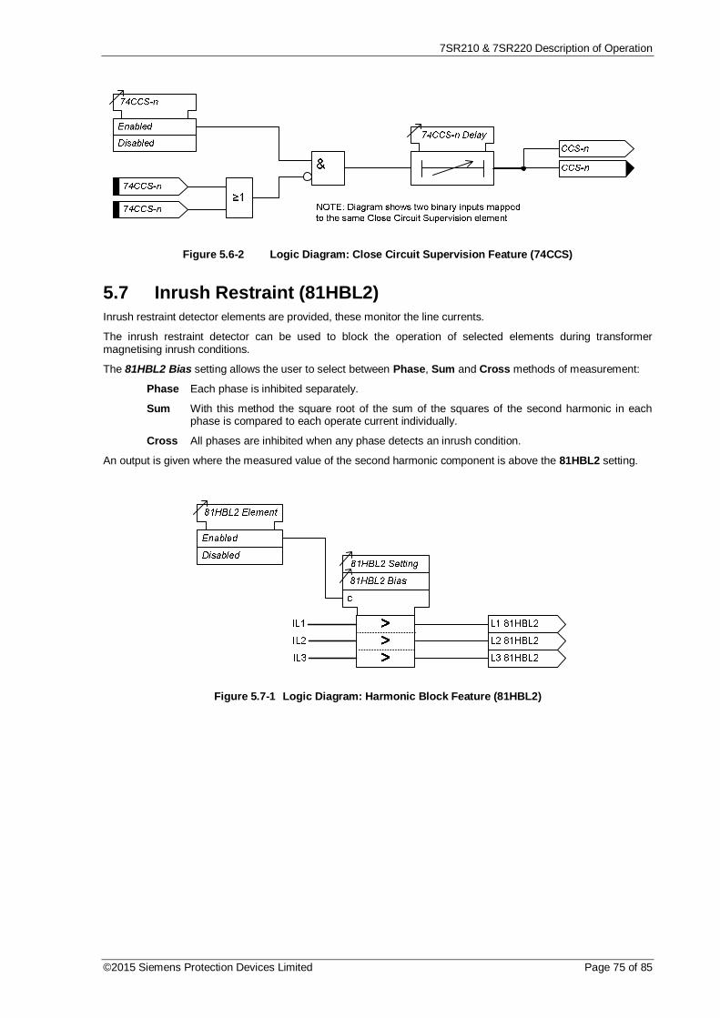
7SR210 & 7SR220 Description of Operation
©2015 Siemens Protection Devices Limited Page 75 of 85
Figure 5.6-2 Logic Diagram: Close Circuit Supervision Feature (74CCS)
5.7 Inrush Restraint (81HBL2)Inrush restraint detector elements are provided, these monitor the line currents.
The inrush restraint detector can be used to block the operation of selected elements during transformermagnetising inrush conditions.
The 81HBL2 Bias setting allows the user to select between Phase, Sum and Cross methods of measurement:
Phase Each phase is inhibited separately.
Sum With this method the square root of the sum of the squares of the second harmonic in eachphase is compared to each operate current individually.
Cross All phases are inhibited when any phase detects an inrush condition.
An output is given where the measured value of the second harmonic component is above the 81HBL2 setting.
Figure 5.7-1 Logic Diagram: Harmonic Block Feature (81HBL2)

7SR210 & 7SR220 Description of Operation
Page 76 of 85 ©2015 Siemens Protection Devices Limited
5.8 Load Blinder (21)Load Blinders are used with directional overcurrent protection elements to block tripping during sustained heavyload periods in distribution networks.
A Load Blinder element is provided in the 7SR22 relay with two operating modes, three-phase and single-phase.
5.8.1 Load Blinder (21) Three-PhaseThree-phase mode uses positive sequence impedance Z1. Both the negative sequence overcurrent threshold(Blinder I2 > Block) and the under-voltage threshold (Blinder V< Block) are used to block the function.
21LB-3P Angle sets the angle for the load blinder region.
21LB-3P Impedance sets the impedance of the load blinder region.
21LB-3P VPPS sets the level of positive phase sequence voltage.
21LB-3P IPPS sets the level of negative phase sequence current.
Operation of the element can be inhibited from: -
Inhibit LB A binary input, virtual input, function key or remote data communications
The design of Load Blinder 3Ph makes consideration that protection blocking should be issued only duringdefinable allowable system power flow conditions i.e. an overcurrent blocking signal can only be issued when: -
a. Positive Sequence Voltage Vpps is not significantly changed, when the Vpps is above the 21LB-3PVPPS Setting.AND
b. Negative Sequence Current Inps is lower than 21LB-3P INPS SettingAND
c. Distributed generators feed in PPS current into the system. In case of high load in system due todistributed generation hence resulting in change of Zpps.Zpps is calculated from Vpps and Ipps. The magnitude and angle of Zpps is compared with 21LB-3PImpedance and 21LB-3P Angle to determine if the impedance is in operate or block and/or FWD orREV zone.
Figure 5.8.1-1 Logic Diagram: Load Blinder Three-Phase
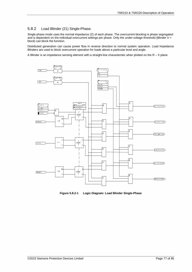
7SR210 & 7SR220 Description of Operation
©2015 Siemens Protection Devices Limited Page 77 of 85
5.8.2 Load Blinder (21) Single-Phase.Single-phase mode uses the normal impedance (Z) of each phase. The overcurrent blocking is phase segregatedand is dependent on the individual overcurrent settings per phase. Only the under-voltage threshold (Blinder V <block) can block the function.
Distributed generation can cause power flow in reverse direction to normal system operation. Load ImpedanceBlinders are used to block overcurrent operation for loads above a particular level and angle.
A Blinder is an impedance sensing element with a straight-line characteristic when plotted on the R – X plane
Figure 5.8.2-1 Logic Diagram: Load Blinder Single-Phase

7SR210 & 7SR220 Description of Operation
Page 78 of 85 ©2015 Siemens Protection Devices Limited
T2T1
90MVA132/33kV
-10% to +20%(Δ1%)Z = 8%
1574A
1600/1AOvercurrentFwd setting:= 90% of 50%=40.5MVA= 709A @ 33kV
33000/110V
Load blinders used to block overcurrentrelay so that tripping does not occur forload current levels with a P.F. 0.94 toUnity.
+R
+X
PhaseFault
BlockZone
LoadImpedance
b
a
NominalImpedanceZ = 1p.u. =VL / (√3 x I)
c-R
-X
Vpps value Point 1Point 2
Point 3Point 4
0360
Trip LevelI = Vs / Z
OperateZone
a = 21LB-3P Impedancesettingb = 21LB-3P Angle +vesettingc = 21LB-3P Angle -vesetting
Point 6Point 5
Fwd
BlockZone
LoadImpedance
ba
c
Point 7
Point 10Point 9
Point 8
Figure 5.8.2-2 Load Blinder and Angle

7SR210 & 7SR220 Description of Operation
©2015 Siemens Protection Devices Limited Page 79 of 85
Section 6: Other Features
6.1 Data CommunicationsTwo communication ports, COM1 and COM2 are provided. RS485 connections are available on the terminalblocks at the rear of the relay (COM1). A USB port, COM 2, is provided at the front of the relay for local accessusing a PC.
Optionally, additional communication ports are available: -
2x fibre optic with ST connectors and 1x IRIG-B – (COM3 and COM 4),
1x RS485 and 1x IRIG-B – (COM 3),
1x RS232 and IRIG-B – (COM 3),
2x Electrical Ethernet with RJ45 connectors IEC 61850 - (COM 3 and COM 4),
2x Optical Ethernet with Duplex LC 100BaseF connectors IEC 61850 - (COM 3 and COM 4).
Communication is compatible with Modbus-RTU, IEC60870-5-103 FT 1.2, DNP 3.0 and IEC 61850 transmissionand application standards.
For communication with the relay via a PC (personal computer) a user-friendly software package, ReydispEvolution, is available to allow transfer of relay settings, waveform records, event records, fault data records,Instruments/meters and control functions. Reydisp Evolution is compatible with IEC60870-5-103.
Data communications operation is described in detail in the Data Communications Definitions section.
6.2 CB MaintenanceSeveral CB operations counters are provided -:
CB Total Trip Count: Increments on each trip command issued. During an auto-reclose sequence, if the target count is reached the relay willperform one Delayed Trip and lockout.
CB Delta Trip Count: Additional counter which can be reset independently of theTotal Trip Counter. This can be used, for example, forrecording trip operations between visits to a substation.
CB Count to AR Block: Displays the number of CB trips experienced by the CB.When the target is reached the relay will only do 1 DelayedTrip to Lockout.
CB Frequent Ops Count Logs the number of trip operations in a rolling window periodof one hour. During an auto-reclose sequence, if the targetcount is reached the relay will perform one Delayed Trip andlockout.
An I2t counter is also included; this can provide an estimation of contact wear and maintenance requirements. Thealgorithm works on a per phase basis, measuring the arcing current during faults. The I2t value at the time of tripis added to the previously stored value and an alarm is given when any one of the three phase running countsexceeds the set Alarm limit. The (t) value is the time between CB contacts separation when an arc is formed,Separation Time, and the CB Clearance time.
Binary outputs can be mapped to each of the above counters, these outputs are energised when the user definedCount Target or Alarm Limit is reached.
6.2.1 Output Matrix Test
The feature is only visible from the Relay fascia and allows the user to operate the relays functions. The test ofthe function will automatically operate any Binary Inputs or LED’s already assigned to that function. Any protectionfunction which is enabled in the setting menu will appear in the Output Matrix Test.

7SR210 & 7SR220 Description of Operation
Page 80 of 85 ©2015 Siemens Protection Devices Limited
6.3 Data Storage
6.3.1 GeneralThe relay stores three types of data records: relay event records, analogue/digital waveform records and faultrecords. Data records are backed up in non-volatile memory and are permanently stored even in the event of lossof auxiliary d.c. supply voltage.
6.3.2 Event RecordsThe event recorder feature allows the time tagging of any change of state (Event) in the relay. As an eventoccurs, the actual event condition is logged as a record along with a time and date stamp to a resolution of 1millisecond. There is capacity for a maximum of 5000 event records that can be stored in the relay and when theevent buffer is full any new record will over-write the oldest. Stored events can be erased using the DATASTORAGE>Clear Events setting.
The following events are logged: -
Change of state of Binary outputs.
Change of state of Binary inputs.
Change of Settings and Settings Group.
Change of state of any of the control functions of the relay.
Protection element operation.
All events can be blocked or made available and uploaded over the data communications channel(s) and can bedisplayed in the ‘Reydisp Evolution’ package in chronological order, allowing the sequence of events to beviewed. Events are also made available spontaneously to an IEC 60870-5-103, Modbus RTU or DNP3.0compliant control system. The function number and event number can also be changed. The events are selectedand edited using the Reydisp software tool.
6.3.3 Waveform Records.Waveform records provide a trace of the instantaneous magnitude of each analogue input channel and the statusof each binary channel i.e. each binary input, binary output, virtual I/O and LED, against time for the duration ofthe record. The values are recorded at every digital sampling point used by the relay software.
Each recorded analogue waveform displays an input identifier, minimum value, maximum value and theinstantaneous values at both cursor positions (user variable). Each binary waveform displays the input/outputnumber and the initiating condition(s) e.g. external input or protection element.
Triggering of waveform storage is configured from the ‘Settings > DATA STORAGE > WAVEFORM STORAGE’menu. Triggering is automatically initiated from operation of any of the selected protection or control elements.Waveform storage can also be triggered from the relay fascia, from a suitably programmed binary input or via thedata comms channel(s).
Waveforms are sampled at a rate of 32 samples per cycle.
The latest 10 records are stored; the most recent is waveform 1. Records are archived by the relay duringquiescent periods. The duration of each stored record is 1s, 2s, 5s or 10s. The user can also specify thepercentage of waveform storage prior to waveform triggering. When the waveform archive buffer is full (i.e. 10records are stored) the triggering of a new waveform record causes the oldest record - waveform 10 – to beoverwritten.
Stored waveforms can be deleted from the relay fascia using the DATA STORAGE > Clear Waveforms setting orvia Reydisp.

7SR210 & 7SR220 Description of Operation
©2015 Siemens Protection Devices Limited Page 81 of 85
6.3.4 Fault RecordsUp to one-hundred fault records can be stored and displayed on the Fascia LCD.
Fault records provide a summary of the relay status at the time of trip, i.e. the element that issued the trip, anyelements that were picked up, the fault type, LED indications, date and time. The Max Fault Rec. Time settingsets the time period from fault trigger during which the operation of any LEDs is recorded.
The relay can be set to automatically display the fault record on the LCD when a fault occurs by enabling theSYSTEM CONFIG> Trip Alert setting. When the trip alert is enabled the fault record will be displayed until thefault is removed.
When examined together the event records and the fault records will detail the full sequence of events leading toa trip.
Fault records are stored in a rolling buffer, with the oldest faults overwritten. The fault storage can be cleared withthe DATA STORAGE>Clear Faults setting or using Reydisp Evolution via Relay > Data Records > Reset DataLog Record.
6.3.5 DemandThe Demand feature can be used to build trend and maximum/minimum demand records. Up to 10,080 individualtime stamped records can be stored at a user defined rate e.g. 35 days @ 5 minute intervals and > 1 year @ 1hour intervals.
Maximum, minimum and mean values of line current, voltage and power (where applicable) are available asinstruments which can be read in the relay INSTRUMENTS MENU or via Reydisp Evolution.
In the menu DATA STORAGE > DEMAND / DATA LOG: -
The Data Log Period setting is used to define the period between stored samples.
The Gn Demand Window setting defines the maximum period of time over which the demand values arecalculated. A new set of demand values is established after expiry of the set time.
The Gn Demand Window Type is the mode used to calculate demand values and can be set to FIXED orPEAK or ROLLING: -
When set to FIXED the maximum, minimum and mean values demand statistics are calculated overfixed Window duration. At the end of each window the internal statistics are reset and a new windowis started.
When set to PEAK the maximum and minimum values since the feature was reset are recorded.
When set to ROLLING the maximum, minimum and mean values demand statistics are calculatedover a moving Window duration. The internal statistics are updated when the window advances.
The statistics can be reset from a binary input or communication command, after a reset the update period andwindow are immediately restarted.
6.3.6 Data LogThe Data log feature can be used to build trend and maximum/minimum demand records. Up to 10,080 individualtime stamped records of each phase current and voltage (where fitted) analogue signal are recorded and storedat a user defined rate e.g. 35 days @ 5 minute intervals and > 1 year @ 1 hour intervals.

7SR210 & 7SR220 Description of Operation
Page 82 of 85 ©2015 Siemens Protection Devices Limited
6.3.7 Energy StorageThe measured Power is continuously integrated (over a one-second window) to produce 4 Energy quantities: -
· Active Export Energy (W)· Active Import Energy (W)· Reactive Export Energy (VAr)· Reactive Import Energy (VAr)
The Direction of Energy transfer is set by: SYSTEM CONFIG> Export Power/Lag VAr. With both Export Power(W) and Lag VAr (VAr) set to be +ve, the Direction of Energy transfer will follow the IEC convention, as shown inthe figure.
ACTIVE ENERGY IMPORT(watts reverse)
IEC CONVENTION : -ve watts
REACTIVE ENERGY IMPORT(vars reverse)
IEC CONVENTION : -ve vars
REACTIVE ENERGY EXPORT(vars forward)
IEC CONVENTION : +ve vars
POWER FACTOR LEADINGACTIVE (W) EXPORT
REACTIVE (VAr) IMPORT
POWER FACTOR LAGGINGACTIVE (W) IMPORT
REACTIVE (VAr) IMPORT
POWER FACTOR LEADINGACTIVE (W) IMPORT
REACTIVE (VAr) EXPORT
0°
+90°
180°
-90°
POWER FACTOR LAGGINGACTIVE (W) EXPORT
REACTIVE (VAr) EXPORT
ACTIVE ENERGY EXPORT(watts forward)
IEC CONVENTION : +ve watts
Figure 6.3.7-1 Energy Direction Convention
Setting either the Export Power (W) or Lag VAr (VAr) to be -ve, will reverse the Direction of the Energy transferfor these quantities. So forward VAr will then be reported as Imported Reactive Energy, and forward Watts will bereported as Exported Active Energy.
When the accumulated Energy quantities reach a set increment, the Relay issues a pulse to the binary outputs:OUTPUT CONFIG/OUTPUT MATRIX> Active Exp Pulse, Active Imp Pulse, Reactive Exp Pulse and ReactiveImp Pulse.
The Energy increments are set by the settings: DATA STORAGE/ENERGY STORAGE> Active Exp EnergyUnit, Active Imp Energy Unit, Reactive Exp Energy Unit and Reactive Imp Energy Unit. These setting alsodefine the resolution of the stored energy values reported by instruments and communications protocols. Thevalue is stored in the range 0-999999 which continues from zero automatically when 999999 is reached.
7SR210 & 7SR220 Description of Operation
©2015 Siemens Protection Devices Limited Page 83 of 85
6.3.8 Fault LocatorThe relay provides a single-end type fault locator which is able to estimate the fault position usinganalogue information measured by the relay at one end of the protected circuit during the shortduration of the fault.
Following relay operation due to a system fault, the fault waveform record is automatically evaluated toestablish the fault type in terms of the phase(s) affected and the relevant current and voltage is usedto calculate the fault impedance. The relay compares this information to a line model based oncharacteristic impedance parameters which are input to the relay as settings and provides an outputestimate of the fault location. This data is presented as a percentage of line length or a distance inmiles or kilometres.
The Positive Sequence Impedance on the protected line must be provided to the relay as settings forimpedance magnitude and characteristic phase angle to enable the distance to fault to be calculated.
The Earth Fault return impedance is specified in terms of the ratio of zero to positive sequenceimpedance magnitudes and the characteristic phase angle of the zero sequence impedance. Thecharacteristic angle of the zero sequence impedance is often significantly different to that of thepositive sequence impedance.
When power systems are earthed through compensation (Peterson) coils, the earth fault currents areextremely low and are not proportional to fault location. Impedance based fault location cannot beused for earth faults. Phase-to-phase fault location can be estimated. On networks of this type it ispossible to have two earth-faults on the network simultaneously on different phases of the same circuitwhich will appear as a phase-to-phase fault. This is known as a Cross-Country fault. In these casesthe measured impedance cannot give an accurate estimate of the fault condition. The 7SR22 relayprovides detection of this condition using the measured zero sequence voltage to positive sequencevoltage ratio (U0/U1) to allow the possible cross-country fault to be reported. This threshold isadjustable by a user setting.
Fault Location is reported for faults calculated in a zone which extends to 200 % of the forward lineimpedance and 10 % in the reverse direction. High resistance fault results where fault resistance iscalculated as up to 20 times the line impedance are reported. For faults beyond these limits, themessage ‘No Location’ is reported.
The Fault Location estimation is initiated by operation of the Trip Output. Some protection elementsmay be set to provide tripping for system conditions where a fault location is not applicable. Theinitiation of the Fault Locator can be inhibited by user settings.
The settings for the Fault Locator are found as a sub-menu in the Data Storage menu.
The Fault Locator result data is available in the Fault Data records and can be viewed at the relayfascia and downloaded from the relay.
6.4 MeteringThe metering feature provides real-time data available from the relay fascia in the ‘Instruments Mode’ or via thedata communications interface.
The Primary values are calculated using the CT and VT ratios set in the CT/VT Config menu.
The text displayed in the relays ‘Instruments Mode’ associated with each value can be changed from the defaulttext using the Reydisp software tool.
The user can add the meters that are most commonly viewed to a ‘Favourites’ window by pressing the ‘ENTER’key when viewing a meter. The relay will scroll through these meters at an interval set in the SystemConfig/Favourite Meters Timer menu.

7SR210 & 7SR220 Description of Operation
Page 84 of 85 ©2015 Siemens Protection Devices Limited
6.5 Operating ModeThe relay has three operating modes, Local, Remote and Out of Service. The following table identifies thefunctions operation in each mode.
The modes can be selected by the following methods: -
SYSTEM CONFIG>RELAY MODE setting, a Binary Input or Command
Table 6.5-1 Operation Mode
OPERATION REMOTE MODE LOCAL MODE SERVICE MODE
ControlRear Ports Enabled Disabled DisabledFascia (Control Mode) Disabled Enabled DisabledUSB Disabled Enabled DisabledBinary Inputs Setting Option Setting Option EnabledBinary Outputs Enabled Enabled DisabledReportingSpontaneousIEC Enabled Enabled DisabledDNP Enabled Enabled DisabledGeneral InterrogationIEC Enabled Enabled DisabledDNP Enabled Enabled DisabledMODBUS Enabled Enabled DisabledChanging of SettingsRear Ports Enabled Disabled EnabledFascia Enabled Enabled EnabledUSB Disabled Enabled EnabledHistorical InformationWaveform Records Enabled Enabled EnabledEvent Records Enabled Enabled EnabledFault Information Enabled Enabled EnabledSetting Information Enabled Enabled Enabled
6.6 Control ModeThis mode provides convenient access to commonly used relay control and test functions. When any of the itemslisted in the Control Mode list are selected, control is initiated by pressing the ENTER key. The user is promptedto confirm the action, again by pressing the ENTER key, before the command is executed.
Control Mode commands are password protected using the Control Password function – see section 6.9.
6.7 Real Time ClockTime and date can be set either via the relay fascia using appropriate commands in the System Config menu, viathe data comms channel(s) or via the optional IRIG-B input. Time and date are maintained while the relay is de-energised by a back up storage capacitor.
In order to maintain synchronism within a substation, the relay can be synchronised to the nearest second orminute using the IEC 60870-5-103 protocol, optional IRIG-B input or binary input.
The default date is set at 01/01/2000 deliberately to indicate the date has not yet been set. When editing theTime, only the hours and minutes can be edited. When the user presses ENTER after editing the seconds arezeroed and the clock begins running.
7SR210 & 7SR220 Description of Operation
©2015 Siemens Protection Devices Limited Page 85 of 85
6.7.1 Time Synchronisation - Data Communication InterfaceWhere the data comms channel(s) is connected the relay can be directly time synchronised using the global timesynchronisation. This can be from a dedicated substation automation system or from ‘Reydisp Evolution’communications support software.
6.7.2 Time Synchronisation – Binary InputA binary input can be mapped Clock Sync from BI. The seconds or minutes will be rounded up or down to thenearest value when the BI is energised. This input is leading edge triggered.
6.7.3 Time Synchronisation – IRIG-B (Optional)A BNC connector on the relay rear provides an isolated IRIG-B time synchronisation port. The IRIG-B inputexpects a modulated 3-6 Volt signal and provides time synchronisation to the nearest millisecond.
6.8 Settings GroupsThe relay provides eight groups of settings – Group number (Gn) 1 to 8. At any one time only one group ofsettings can be ‘active’ – SYSTEM CONFIG>Active Group setting.
It is possible to edit one group while the relay operates in accordance with settings from another ‘active’ groupusing the View/Edit Group setting.
Some settings are independent of the active group setting i.e. they apply to all settings groups. This is indicatedon the top line of the relay LCD – where only the Active Group No. is identified. Where settings are groupdependent this is indicated on the top line of the LCD by both the Active Group No. and the View Group No. beingdisplayed.
A change of settings group can be achieved either locally at the relay fascia, remotely over the data commschannel(s) or via a binary input. When using a binary input an alternative settings group is selected only whilst theinput is energised (Select Grp Mode: Level triggered) or latches into the selected group after energisation of theinput (Select Grp Mode: Edge triggered).
6.9 Password FeatureThe relay incorporates two levels of password protection – one for settings, the other for control functions.
The programmable password feature enables the user to enter a 4 character alpha numeric code to secureaccess to the relay functions. A Password of NONE indicates that a Password has not been set and that thePassword feature is disabled. Where a Relay is delivered with the Password already set, this will be AAAA. Thepassword must be entered twice as a security measure against accidental changes. Once a password has beenentered then it will be required thereafter to change settings or initiate control commands. Passwords can be de-activated by using the password to gain access and by entering the password NONE. Again this must be enteredtwice to de-activate the security system.
As soon as the user attempts to change a setting or initiate control the password is requested before any changesare allowed. Once the password has been validated, the user is ‘logged on’ and any further changes can be madewithout re-entering the password. If no more changes are made within 1 hour then the user will automatically be‘logged off’, re-enabling the password feature.
The Settings Password prevents unauthorised changes to settings from the front fascia or over the data commschannel(s). The Control Password prevents unauthorised operation of controls in the relay Control Menu from thefront fascia.
The password validation screen also displays a numerical code. If the password is lost or forgotten, this codeshould be communicated to Siemens Protection Devices Ltd. and the password can be retrieved.

The copyright and other intellectual property rights in this document, and in any model or article produced from it(and including any registered or unregistered design rights) are the property of Siemens Protection DevicesLimited. No part of this document shall be reproduced or modified or stored in another form, in any data retrievalsystem, without the permission of Siemens Protection Devices Limited, nor shall any model or article bereproduced from this document unless Siemens Protection Devices Limited consent.
While the information and guidance given in this document is believed to be correct, no liability shall be acceptedfor any loss or damage caused by any error or omission, whether such error or omission is the result ofnegligence or any other cause. Any and all such liability is disclaimed.
© 2013 Siemens Protection Devices Limited
7SR210 Non-Directional Relay
7SR220 Directional Relay
Configuration Guide

7SR210 & 7SR220 Configuration Guide
Page 2 of 15 © 2013 Siemens Protection Devices Limited
Document Release HistoryThis document is issue 2015/06.
2011/05 First issue
2013/01 Typographical revisions and added data. Updated in line with software release.
2014/06 Typographical revisions and added data. Updated in line with software release.
2015/06 Typographical revisions amended drawings and added data. Updated in line with softwarerelease.
Software Revision History2011/05 2435H85008R7a-7a (7SR210)
2435H85009R7a-7a (7SR220)
First Release
2013/01 2435H85008R7c-7b (7SR210)
2435H85009R7c-7b (7SR220)
Introduced journaling file system.Added 61850 logical nodes for CB Counters, metering, 50BF,46BC,81HBL2 and line check.Added Line Check on non-AR devices.Added 74CCS Close Circuit Supervision.
2014/06 2435H85008R7f-7d (7SR210)
2435H85009R7f-7d (7SR220)
Added Fault Locator feature and Check Sync feature.Fault data transmitted over 103.Additional communications data, control features, meters.
2015/06 2435H85008R8a-7e (7SR210)
2435H85009R8a-7f (7SR220)
Added Power Factor Meters, Load Blinding feature, Arc FlashDetector. Over current TM Setting Range extended.
7SR210 & 7SR220 Configuration Guide
© 2013 Siemens Protection Devices Limited Page 3 of 15
ContentsDocument Release History ................................................................................................................................. 2Software Revision History .................................................................................................................................. 2Contents ............................................................................................................................................................ 3Section 1: Introduction ....................................................................................................................................... 5
1.1 Relay Menus And Display .................................................................................................................. 51.2 Operation Guide ................................................................................................................................ 7
1.2.1 User Interface Operation ...................................................................................................... 7Section 2: Configuring the Relay Using Reydisp Evolution ................................................................................ 10
2.1 Physical Connection ........................................................................................................................ 102.1.1 Front USB connection ........................................................................................................ 102.1.2 Standard rear RS485 connection ........................................................................................ 112.1.3 Optional rear fibre optic connection ..................................................................................... 112.1.4 Optional rear RS485 + IRIG-B connection ........................................................................... 122.1.5 Optional rear RS232 + IRIG-B connection ........................................................................... 122.1.6 Optional Rear EN100 Ethernet Module ............................................................................... 132.1.7 Configuring Relay Data Communication .............................................................................. 142.1.8 Connecting to the Relay via Reydisp Evolution .................................................................... 15

7SR210 & 7SR220 Configuration Guide
Page 4 of 15 © 2013 Siemens Protection Devices Limited
List of FiguresFigure 1.1-1 Menu………………………………………………………………………………………….. ....................... 4Figure 1.1-2 Fascia Contrast Symbol…………………………………………………………….……… ........................ 4Figure 1.1-3 Relay Fascia…………………………………………………………….……… ........................................ 5Figure 1.2-1 Relay Identifier Screen…………………………………………………..………….…… ........................ …6Figure 1.2-3 Menu Structure for 7SR21 relay……………………………………..…………….…… ........................ …7Figure 1.2-4 Menu Structure for 7SR22 relay……………………………………………………...… ........................ …8Figure 2.1-1 USB connection to a PC……………………………………………….……………….…..................... …10Figure 2.1-2 Standard rear RS485 connection to a PC………………………………………….…………………. .. …11Figure 2.1-3 Additional (Optional) rear fibre optic connection to a PC………………………………………….… .. …11Figure 2.1-4 Additional (Optional) rear RS485 + IRIG-B connection to a PC………………….…………………... …12Figure 2.1-5 Additional (Optional) rear RS232 + IRIG-B connection to a PC…………………………………….……12Figure 2.1-6 Optional Rear EN100 Ethernet Module…………………………………….… .................................. …13Figure 2.1-7 PC Comm Port Selection…………………………………………………………….… ........................ …15

7SR210 & 7SR220 Configuration Guide
© 2013 Siemens Protection Devices Limited Page 5 of 15
Section 1: Introduction
1.1 Relay Menus And DisplayAll relay fascias contain the same access keys although the fascias may differ in appearance from model tomodel. The basic menu structure is also the same in all products and consists of four main menus, these being,
Settings Mode - allows the user to view and (if allowed via the settings mode password) change settings in therelay.
Instruments Mode - allows the user to view the relay meters e.g. current, voltage etc.
Fault Data Mode - allows the user to view the type and data of any fault that the relay has detected.
Control Mode - allows the user to control external plant under the relays control for example the CB (if allowedvia the control mode password)
The menus can be viewed via the LCD by pressing the access keys as below,
Figure 1.1-1 Menu Navigation
Pressing CANCEL returns to the Identifier screen
LCD Contrast
To change the contrast on the LCD insert a flat nosed screwdriver into the screwhead below the contrast symbol,turning the screwhead left or right decreases and increases the contrast of the LCD.
Figure 1.1-2 Fascia Contrast symbol

7SR210 & 7SR220 Configuration Guide
Page 6 of 15 © 2013 Siemens Protection Devices Limited
Figure 1.1-3 Relay Fascia (Please note fascia may differ from illustration)

7SR210 & 7SR220 Configuration Guide
© 2013 Siemens Protection Devices Limited Page 7 of 15
1.2 Operation Guide1.2.1 User Interface Operation
The basic menu structure flow diagram is shown in Figure 1.2-2. This diagram shows the main modes of display:Settings Mode, Instrument Mode, Fault Data Mode and Control Mode.
When the relay leaves the factory all data storage areas are cleared and the settings set to default as specified insettings document.
When the relay is first energised the user is presented with the following message: -
7SR220
_______________________________
ENTER to CONTROL
Figure 1.2-1 Relay Identifier Screen
On the factory default setup the relay LCD should display the relay identifier, on each subsequent power-on thescreen that was showing before the last power-off will be displayed.
The push-buttons on the fascia are used to display and edit the relay settings via the LCD, to display and activatethe control segment of the relay, to display the relays instrumentation and Fault data and to reset the outputrelays and LED’s.
The five push-buttons have the following functions:
READ DOWN READ UP
Used to navigate the menu structure.
ENTER
The ENTER push-button is used to initiate and accept setting changes.
When a setting is displayed pressing the ENTER key will enter the edit mode, the setting will flash and can nowbe changed using the or buttons. When the required value is displayed the ENTER button is pressed againto accept the change.
When an instrument is displayed pressing ENTER will toggle the instruments favourite screen status.
CANCEL
This push-button is used to return the relay display to its initial status or one level up in the menu structure.Pressed repeatedly will return to the Relay Identifier screen. It is also used to reject any alterations to a settingwhile in the edit mode.
TEST/RESET
This push-button is used to reset the fault indication on the fascia. When on the Relay Identifier screen it alsoacts as a lamp test button, when pressed all LEDs will momentarily light up to indicate their correct operation. It isalso moves the cursor right when navigating through menus and settings.

7SR210 & 7SR220 Configuration Guide
Page 8 of 15 © 2013 Siemens Protection Devices Limited
Figure 1.2-2 Typical Menu Structure for 7SR21 relay
SETTINGS MODE INSTRUMENTS MODE FAULT DATA MODE
SYSTEM CONFIG
FUNCTION CONFIG
CT/VT CONFIG
SUPERVISIONCB FAIL
BROKEN CONDUCTOR
TRIP CCT SUPERVISION
AUTORECLOSE PROT’N
AUTORECLOSE CONFIG
CURRENT PROT’NPHASE OVERCURRENT
DERIVED E/F
MEASURED E/F
SENSITIVE E/F
RESTRICTED E/F
COLD LOAD
NPS OVERCURRENT
UNDER CURRENT
THERMAL
CONTROL & LOGIC
CIRCUIT BREAKER
QUICK LOGIC
INPUT CONFIG
OUTPUT CONFIG
CB MAINTENANCE
DATA STORAGE
INPUT MATRIX
FUNCTION KEY MATRIX
BINARY INPUT CONFIG
OUTPUT MATRIX
BINARY OUTPUT CONFIG
LED CONFIG
PICKUP CONFIG
CB COUNTERS
I^2T CB WEAR
CONTROL MODE
CB TRAVELLING CLOSE I OPEN
AR : OUT OF SERVICE
AR : TRIP & RECLOSE
AR : TRIP & LOCKOUT
E/F IN
HOTLINE WORKING : OUT
INST PROT'N : IN
IN I OUT
CONFIRM ACTION
CONFIRM ACTION
IN I OUT
IN I OUT
IN I OUT
FAVOURITE METERS
CURRENT METERS
THERMAL METERS
AUTORECLOSE METERS
MAINTENANCE METERS
GENERAL ALARM METERS
BINARY INPUT METERS
BINARY OUTPUT METERS
VIRTUAL METERS
MISCELLANEOUS
7SR22 ARGUS____________________________
ENTER to CONTROL
NUMBER OF FAULTS
COMMUNICATIONS
MANUAL CLOSE
46IT46DT
37-137-2
INRUSH DETECTOR
GENERAL ALARMS
50-1
51-151-2
50-2
51N-151N-250N-150N-2
50G-1
51G-151G-2
50G-2
51SEF-151SEF-250SEF-150SEF-2
COMMUNICATION METERS
DEMAND
SEF IN IN I OUT

7SR210 & 7SR220 Configuration Guide
© 2013 Siemens Protection Devices Limited Page 9 of 15
Figure 1.2-3 Typical Menu Structure for 7SR22 relay
SETTINGS MODE INSTRUMENTS MODE FAULT DATA MODE
SYSTEM CONFIG
FUNCTION CONFIG
CT/VT CONFIG
PHASE U/O VOLTAGE
NPS OVERVOLTAGE
U/O FREQUENCY
VOLTAGE PROT’N
SUPERVISION
27/59-127/59-227/59-327/59-4
47-147-2
59NIT59NDT
81-181-281-381-481-581-6
CB FAIL
VT SUPERVISION
CT SUPERVISION
BROKEN CONDUCTOR
TRIP CCT SUPERVISION
AUTORECLOSE PROT’N
AUTORECLOSE CONFIG
CURRENT PROT’NPHASE OVERCURRENT
51-3
50-1
51N-4
VOLTAGE CONT O/C
DERIVED E/F
MEASURED E/F51G-3
50G-1
50G-3
SENSITIVE E/F
RESTRICTED E/F
COLD LOAD
NPS OVERCURRENT
UNDER CURRENT
THERMAL
CONTROL & LOGIC
CIRCUIT BREAKER
QUICK LOGIC
INPUT CONFIG
OUTPUT CONFIG
CB MAINTENANCE
DATA STORAGE
INPUT MATRIX
FUNCTION KEY MATRIX
BINARY INPUT CONFIG
OUTPUT MATRIX
BINARY OUTPUT CONFIG
LED CONFIG
PICKUP CONFIG
CB COUNTERS
I^2T CB WEAR
NEUTRAL OVERVOLTAGE
CONTROL MODE
CB TRAVELLING CLOSE I OPEN
AR : OUT OF SERVICE
AR : TRIP & RECLOSE
AR : TRIP & LOCKOUT
E/F IN
HOTLINE WORKING : OUT
INST PROT'N : IN
IN I OUT
CONFIRM ACTION
CONFIRM ACTION
IN I OUT
IN I OUT
IN I OUT
FAVOURITE METERS
CURRENT METERS
VOLTAGE METERS
FREQUENCY METERS
POWER METERS
ENERGY METERS
THERMAL METERS
AUTORECLOSE METERS
MAINTENANCE METERS
GENERAL ALARM METERS
BINARY INPUT METERS
BINARY OUTPUT METERS
VIRTUAL METERS
COMMUNICATION METERS
7SR22 ARGUS____________________________
ENTER to CONTROL
NUMBER OF FAULTS
COMMUNICATIONS
MANUAL CLOSE
51-151-2
51-4
50-250-350-4
51N-151N-251N-3
50N-150N-250N-350N-4
51G-151G-2
51G-4
50G-2
50G-4
51SEF-151SEF-251SEF-351SEF-450SEF-150SEF-250SEF-350SEF-4
46IT46DT
37-137-2
Vx U/O VOLTAGE
INRUSH DETECTOR
GENERAL ALARMS
DIRECTIONAL METERS
MISCELLANEOUS METERS
FUNCTION KEY CONFIG
DEMAND
SEF IN IN I OUT

7SR210 & 7SR220 Configuration Guide
Page 10 of 15 © 2013 Siemens Protection Devices Limited
Section 2: Configuring the Relay Using Reydisp Evolution
To set the relay using the communication port the user will need the following:-
PC with Reydisp Evolution Installed. (This can be download from our website www.energy.siemens.com andfound under the submenu ‘Software’). This software requires windows 2000-service pack 4 or above, or windowsXP with service pack 2 or above.
2.1 Physical ConnectionThe relay can be connected to Reydisp Evolution via any of the communication ports on the relay. Suitablecommunication Interface cable and converters are required depending which port is being used.
2.1.1 Front USB connection
To connect your pc locally via the front USB port.
Figure 2.1-1 USB connection to a PC

7SR210 & 7SR220 Configuration Guide
© 2013 Siemens Protection Devices Limited Page 11 of 15
2.1.2 Standard rear RS485 connection
Figure 2.1-2 Standard rear RS485 connection to a PC
2.1.3 Optional rear fibre optic connection
Figure 2.1-3 Additional (Optional) rear fibre optic connection to a PC
Sigma devices have a 25 pin female D connector with the following pin out.
Pin Function2 Transmit Data3 Received Data4 Request to Send5 Clear to Send6 Data set ready7 Signal Ground8 Received Line Signal Detector20 Data Terminal Ready

7SR210 & 7SR220 Configuration Guide
Page 12 of 15 © 2013 Siemens Protection Devices Limited
2.1.4 Optional rear RS485 + IRIG-B connection
Figure 2.1-4 Additional (Optional) rear RS485 + IRIG-B connection to a PC
2.1.5 Optional rear RS232 + IRIG-B connection
Figure 2.1-5 Additional (Optional) rear RS232 + IRG-B connection to a PC
Pin Function1 Carrier Direct (CD)2 Receive Data (RXD)3 Transmit Data (TXD)4 Data Terminal Ready (DTR)5 Signal Ground (GND)6 Data set ready (DSR)7 Request to send (RTS)8 Clear to Send (CTS)9 Ring Indicator (RI)

7SR210 & 7SR220 Configuration Guide
© 2013 Siemens Protection Devices Limited Page 13 of 15
2.1.6 Optional Rear EN100 Ethernet Module
Connections are made on the rear underside of the relay either RJ45 sockets (electrical) or Duplex LC(fibre optic) connectors depending on the option ordered.
LED yellow
LED green
LED yellow
LED green
Ch 1 Ch 2
Ethernet – EN100-E
EN100 Module – RJ45 Interface
Ethernet – EN100-O
Ch 1 Ch 2
EN100 Module – Duplex-LC Interface
Green LED (Physical Link)Off – No linkOn – Link present
Yellow LED (Activity)Off – No trafficOn/flashing - Traffic
Figure 2.1-6 EN100 Ethernet Module

7SR210 & 7SR220 Configuration Guide
Page 14 of 15 © 2013 Siemens Protection Devices Limited
2.1.7 Configuring Relay Data Communication
Using the keys on the relay fascia scroll down the settings menu’s into the ‘communications’ menu and changethe settings for the communication port used on the relay. All of the below settings may not be available in allrelay types. Reydisp Evolution software uses IEC60870-5-103 protocol to communicate.
COM1 – Standard RS485 Rear Port
COM2 - USB Port
COM3 – Optional Fibre Optic, RS485, RS232 or Ethernet Port
COM4 – Additional (Optional) Rear Connection**
LAN – Optional Ethernet Ports
Setting name Range Default Units Notes
Station Address1 – 254 for IEC60870-5-1030 – 247 for Modbus RTU0 – 65520 for DNP3.0
0
Address given to relay toidentify that relay fromothers which may be usingthe same path forcommunication as otherrelays for example in a fibreoptic hub
COM1-RS485 Protocol OFF, IEC60870-5-103,MODBUS-RTU, DNP3.0
IEC60870-5-103
COM1 is the rear mountedRS485 port
COM1-RS485 BaudRate
75 110 150 300 600 12002400 4800 9600 1920038400
19200
COM1-RS485 Parity NONE, ODD, EVEN EVEN
COM2-USB ProtocolOFF, IEC60870-5-103,DNP3.0, MODBUS-RTU,ASCII
IEC60870-5-103 COM2 is the front USB port
COM2-USB Baud Rate
75 110 150 300 600 12002400 4800 9600 1920038400 57600 115200230400 460800 921600
Auto detects Auto detects baud rate viaConnection Manager Setting
COM2-USB Parity NONE, ODD, EVEN EVEN
COM3 Protocol OFF, IEC60870-5-103,MODBUS-RTU, DNP3.0
IEC6-0870-5-103
COM3 This is an optionalrear mounted connection
COM3 Baud Rate75 110 150 300 600 12002400 4800 9600 1920038400 57600 115200
57600
COM3 Parity NONE, ODD, EVEN EVEN
COM3 Line Idle* LIGHT ON, LIGHT OFF LIGHT OFF
COM3 Data echo* ON, OFF OFF
COM4 Protocol** OFF, IEC60870-5-103,MODBUS-RTU, DNP3.0 OFF COM4 This is an optional
rear mounted connection
COM4 Baud Rate**75 110 150 300 600 12002400 4800 9600 1920038400
19200
COM4 Parity** NONE, OFF, EVEN EVEN
COM4 Line Idle** LIGHT ON, LIGHT OFF LIGHT OFF
COM4 Data echo** ON, OFF OFF
*Not applicable for RS485 or RS232 interface modules.**Fibre Optic Module only

7SR210 & 7SR220 Configuration Guide
© 2013 Siemens Protection Devices Limited Page 15 of 15
2.1.8 Connecting to the Relay via Reydisp Evolution
When Reydisp Evolution software is running all available communication ports of the PC will automatically bedetected.On the start page tool bar open up the sub-menu File > Connect.
The ‘Communication Manager’ window will display all available communication ports. With the preferred porthighlighted, select the ‘Properties’ option and ensure the baud rate and parity match that selected in the relayData Comms settings. Select ‘Connect’ to initiate the relay-PC connection.
Figure 2.1-7 PC Comm Port Selection
Via the Relay > Set Address > Address set the relay address (1-254) or alternatively search for connecteddevices using the Relay > Set Address > Device Map. The relay can now be configured using the ReydispEvolution software. Please refer to the Reydisp Evolution Manual for further guidance.

The copyright and other intellectual property rights in this document, and in any model or article produced fromit (and including any registered or unregistered design rights) are the property of Siemens Protection DevicesLimited. No part of this document shall be reproduced or modified or stored in another form, in any dataretrieval system, without the permission of Siemens Protection Devices Limited, nor shall any model or articlebe reproduced from this document unless Siemens Protection Devices Limited consent.
While the information and guidance given in this document is believed to be correct, no liability shall beaccepted for any loss or damage caused by any error or omission, whether such error or omission is the resultof negligence or any other cause. Any and all such liability is disclaimed.
© 2013 Siemens Protection Devices Limited
7SR210 Non-Directional Relay
Settings Guide

7SR210 Settings Guide
Page 2 of 64 © 2013 Siemens Protection Devices Limited
Document Release History
This document is issue 2015/06.
2011/05 First issue
2013/01 Typographical revisions and added data. Updated in line with software release.
2014/06 Typographical revisions and added data. Updated in line with software release.
2015/06 Typographical revisions and added data. Updated in line with software release.
Software Revision History2011/05 2435H85008R7a-7a (7SR210) First Release
2013/01 2435H85008R7c-7b (7SR210) Introduced journaling file system.Added 61850 logical nodes for CB Counters, metering, 50BF,46BC, 81HBL2 and line check.Added Line Check on non-AR devices.Added 74CCS Close Circuit Supervision.
2014/06 2435H85008R7f-7d (7SR210) Fault data transmission over IEC 60870-5-103.Additional communications data, control features, meters.
2015/06 2435H85008R8a-7f (7SR210) Added Arc Flash Detector. Over current TM Setting Rangeextended.

7SR210 Settings Guide
©2015 Siemens Protection Devices Limited Page 3 of 64
ContentsDocument Release History .............................................................................................................. 2
Software Revision History ............................................................................................................... 2
1. Function Diagram .................................................................................................................... 5
2. Menu Structure ........................................................................................................................ 6
3. Relay Settings .......................................................................................................................... 73.1. System Config ................................................................................................................. 73.2. CT/VT Config .................................................................................................................. 83.3. Function Config .............................................................................................................. 83.4. Current Protection ........................................................................................................ 11
3.4.1. Phase Overcurrent ............................................................................................ 113.4.1.1. 51-1 ......................................................................................................... 113.4.1.2. 51-2 ......................................................................................................... 113.4.1.3. 50-1 ......................................................................................................... 123.4.1.4. 50-2 ......................................................................................................... 12
3.4.2. Cold Load........................................................................................................... 123.4.3. Derived E/F ........................................................................................................ 13
3.4.3.1. 51N-1 ...................................................................................................... 133.4.3.2. 51N-2 ...................................................................................................... 143.4.3.3. 50N-1 ...................................................................................................... 143.4.3.4. 50N-2 ...................................................................................................... 14
3.4.4. Measured E/F .................................................................................................... 163.4.4.1. 51G-1 ...................................................................................................... 163.4.4.2. 51G-2 ...................................................................................................... 163.4.4.3. 50G-1 ...................................................................................................... 173.4.4.4. 50G-2 ...................................................................................................... 17
3.4.5. Sensitive E/F ..................................................................................................... 173.4.5.1. 51SEF-1 .................................................................................................. 173.4.5.2. 51SEF-2 .................................................................................................. 183.4.5.3. 50SEF-1 .................................................................................................. 183.4.5.4. 50SEF-2 .................................................................................................. 18
3.4.6. Restricted E/F .................................................................................................... 193.4.7. NPS Overcurrent ............................................................................................... 19
3.4.7.1. 46IT ......................................................................................................... 193.4.7.2. 46DT ....................................................................................................... 19
3.4.8. Under Current .................................................................................................... 203.4.8.1. 37-1 ......................................................................................................... 203.4.8.2. 37-2 ......................................................................................................... 203.4.8.3. 37G-1 ...................................................................................................... 203.4.8.4. 37G-2 ...................................................................................................... 20
3.4.9. Thermal .............................................................................................................. 213.4.10. ARC Flash Detector .................................................................................... 21
3.5. Supervision ................................................................................................................... 213.5.1. CB Fail ............................................................................................................... 21

7SR210 Settings Guide
Page 4 of 64 © 2013 Siemens Protection Devices Limited
3.5.2. CT Supervision .................................................................................................. 213.5.3. Broken Conductor .............................................................................................. 223.5.4. Trip CCT Supervision ........................................................................................ 223.5.5. Close CCT Supervision..................................................................................... 223.5.6. Inrush Detector .................................................................................................. 23
3.6. Control & Logic .............................................................................................................. 233.6.1. Autoreclose Prot’n ............................................................................................. 233.6.2. Autoreclose Config ............................................................................................ 25
3.6.2.1. P/F Shots................................................................................................. 253.6.2.2. E/F Shots................................................................................................. 263.6.2.3. SEF Shots ............................................................................................... 273.6.2.4. Extern Shots ........................................................................................... 27
3.6.3. Manual Close ..................................................................................................... 273.6.4. Circuit Breaker ................................................................................................... 283.6.5. QUICK LOGIC .................................................................................................... 28
3.7. Input Config ................................................................................................................... 373.7.1. Input Matrix ......................................................................................................... 373.7.2. Binary Input Config ............................................................................................ 443.7.3. General Alarms .................................................................................................. 45
3.8. Output Config ................................................................................................................ 463.8.1. Output Matrix ...................................................................................................... 463.8.2. Binary Output Config ......................................................................................... 583.8.3. LED Config ......................................................................................................... 593.8.4. Pickup Config ..................................................................................................... 60
3.9. CB Maintenance ............................................................................................................ 613.9.1. CB Counters ....................................................................................................... 613.9.2. I^2T CB Wear ..................................................................................................... 623.9.3. START COUNT ................................................................................................. 62
3.10.Data Storage ................................................................................................................. 623.10.1. Demand Data/Log ........................................................................................ 623.10.2. Waveform Storage ....................................................................................... 623.10.3. Fault Storage ................................................................................................ 633.10.4. Event Storage ............................................................................................... 633.10.5. Communications .......................................................................................... 63

7SR210 Settings Guide
©2015 Siemens Protection Devices Limited Page 5 of 64
1.Function Diagram

7SR210 Settings Guide
Page 6 of 64 © 2013 Siemens Protection Devices Limited
2.Menu Structure

7SR210 Settings Guide
©2015 Siemens Protection Devices Limited Page 7 of 64
3.Relay Settings3.1. System ConfigDescription Range Default
Active Group
Selects which settings group is currently activated
System Frequency
Selects the Power System Frequency from 50 or 60 Hz
50, 60 50 Hz
View/Edit Group
Selects which settings group is currently being displayed
Setting Dependencies
When enabled only active settings are displayed and allothers hidden
Disabled, Enabled Enabled
Favourite Meters Timer
Selects the time delay after which, if no key presses havebeen detected, the relay will begin to poll through anyscreens which have been selected as favouriteinstruments
Off, 1, 2, 5, 10, 15, 30, 60 60 min
Backlight timer
Controls when the LCD backlight turns off
Off, 1, 2, 5, 10, 15, 30, 60 5 min
Date
Sets the date, this setting can only be changed on thefascia or via Relay->Control->Set Time and Date
Time
Sets the time, this setting can only be changed on thefascia or via Relay->Control->Set Time and Date
Curr Set Display
Select whether the Pickup values are shown in terms of xNominal, Primary or Secondary values on the RelayFascia
xNom, Primary, Secondary xNom
E/F Curr Set Display
As Above
xNom, Primary, Secondary xNom
Select Grp Mode
Mode of operation of the group change from status input.Edge triggered ignores the status input once it haschanged to the relevant group, where as with Leveltriggered the relay will only stay in the group it haschanged to whilst the status input is being driven, afterwhich it returns to the previous group.
Edge triggered, Level triggered Edge triggered
Clock Sync. From BI
Real time clock may be synchronised using a binary input(See Clock Sync. in Binary Input Menu)
Disabled, Seconds, Minutes Minutes
Operating Mode
Selects the current operating mode of the relay. This canalso be changed by a binary input mode selection.
Out Of Service, Local, Remote,Local Or Remote
Local OrRemote
Setting Password
Allows a 4 character alpha code to be entered as thepassword. Note that the display shows a passworddependant encrypted code on the second line of thedisplay
(Password) NONE
Control Password
As Above
(Password) NONE

7SR210 Settings Guide
Page 8 of 64 © 2013 Siemens Protection Devices Limited
Description Range Default
Trip Alert
When Enabled the occurrence of a Trip will cause therelay to display the Trip Alert Screen, the only way to leavethis screen is by acknowledging the trip through theTEST/RESET button on the relay fascia
Disabled, Enabled Enabled
General Alarm Alert Disabled, Enabled Enabled
Relay Identifier
An alphanumeric string shown on the LCD normally usedto identifier the circuit the relay is attached to or the relayspurpose
(16 Character String) 7SR210
Circuit Identifier (16 Character String)
3.2. CT/VT ConfigDescription Range Default
Phase Current Input
Selects whether 1 or 5 Amp terminals are being used forphase inputs
1, 5 1 A
Phase CT Ratio Prim
Phase CT ratio to scale primary current instruments
( 6 Character String) 2000 A
Phase CT Ratio Sec
Phase CT ratio to scale secondary current instruments
0.2, 0.21 ... 2, 2.1.....7 1
Earth Current Input
Selects whether 1 or 5 Amp terminals are being used forMeasured Earth inputs
1, 5 1 A
Earth CT Ratio Prim
Measured Earth CT ratio to scale primary currentinstruments
( 6 Character String) 2000 A
Earth CT Ratio Sec
Measured Earth CT ratio to scale secondary currentinstruments
0.2, 0.21 ... 2, 2.1.....7 1
3.3. Function ConfigDescription Range Default
Gn Phase Overcurrent
When set to Disabled, no Phase Overcurrent elements willbe functional and all associated settings will be hidden.(The Setting Dependencies setting being set to Disabledwill make all settings visible but will not allow them tooperate).
Enabled, Disabled Disabled
Gn Cold Load
When set to Disabled, no Cold Load elements will befunctional and all associated settings will be hidden. (TheSetting Dependencies setting being set to Disabled willmake all settings visible but will not allow them to operate).
Enabled, Disabled Disabled
Gn Derived E/F
When set to Disabled, no Derived E/F elements will befunctional and all associated settings will be hidden. (TheSetting Dependencies setting being set to Disabled willmake all settings visible but will not allow them to operate).
Enabled, Disabled Disabled

7SR210 Settings Guide
©2015 Siemens Protection Devices Limited Page 9 of 64
Description Range Default
Gn Measured E/F
When set to Disabled, no Measured E/F elements will befunctional and all associated settings will be hidden. (TheSetting Dependencies setting being set to Disabled willmake all settings visible but will not allow them to operate).
Enabled, Disabled Disabled
Gn Sensitive E/F
When set to Disabled, no Sensitive E/F elements will befunctional and all associated settings will be hidden. (TheSetting Dependencies setting being set to Disabled willmake all settings visible but will not allow them to operate).
Enabled, Disabled Disabled
Gn Restricted E/F
When set to Disabled, no Restricted E/F elements will befunctional and all associated settings will be hidden. (TheSetting Dependencies setting being set to Disabled willmake all settings visible but will not allow them to operate).
Enabled, Disabled Disabled
Gn NPS Overcurrent
When set to Disabled, no NPS Overcurrent elements willbe functional and all associated settings will be hidden.(The Setting Dependencies setting being set to Disabledwill make all settings visible but will not allow them tooperate).
Enabled, Disabled Disabled
Gn Under Current
When set to Disabled, no Under Current elements will befunctional and all associated settings will be hidden. (TheSetting Dependencies setting being set to Disabled willmake all settings visible but will not allow them to operate).
Enabled, Disabled Disabled
Gn Thermal
When set to Disabled, no Thermal elements will befunctional and all associated settings will be hidden. (TheSetting Dependencies setting being set to Disabled willmake all settings visible but will not allow them to operate).
Enabled, Disabled Disabled
Gn CT Supervision
When set to Disabled, no CT Supervision elements will befunctional and all associated settings will be hidden. (TheSetting Dependencies setting being set to Disabled willmake all settings visible but will not allow them to operate).
Enabled, Disabled Disabled
Gn CB Fail
When set to Disabled, no CB Fail elements will befunctional and all associated settings will be hidden. (TheSetting Dependencies setting being set to Disabled willmake all settings visible but will not allow them to operate).
Enabled, Disabled Disabled
Gn Broken Conductor
When set to Disabled, no Broken Conductor elements willbe functional and all associated settings will be hidden.(The Setting Dependencies setting being set to Disabledwill make all settings visible but will not allow them tooperate).
Enabled, Disabled Disabled
Gn Trip Cct Supervision
When set to Disabled, no Trip Cct Supervision elementswill be functional and all associated settings will be hidden.(The Setting Dependencies setting being set to Disabledwill make all settings visible but will not allow them tooperate).
Enabled, Disabled Disabled
Gn Close Cct Supervision
When set to Disabled, no Close Cct Supervision elementswill be functional and all associated settings will be hidden.(The Setting Dependencies setting being set to Disabledwill make all settings visible but will not allow them tooperate).
Enabled, Disabled Disabled
Gn Inrush Detector
When set to Disabled, no Inrush Detector elements will befunctional and all associated settings will be hidden. (TheSetting Dependencies setting being set to Disabled willmake all settings visible but will not allow them to operate).
Enabled, Disabled Disabled

7SR210 Settings Guide
Page 10 of 64 © 2013 Siemens Protection Devices Limited
Description Range Default
Gn CB Counters
When set to Disabled, no Gn CB Counter elements will befunctional and all associated settings will be hidden. (TheSetting Dependencies setting being set to Disabled willmake all settings visible but will not allow them to operate).
Enabled, Disabled Disabled
Gn I^2t CB Wear
When set to Disabled, no Gn I^2t CB Wear elements willbe functional and all associated settings will be hidden.(The Setting Dependencies setting being set to Disabledwill make all settings visible but will not allow them tooperate).
Enabled, Disabled Disabled
Gn Arc Flash Detector
When set to Disabled, no Arc Flash Detector elements willbe functional and all associated settings will be hidden.(The Setting Dependencies setting being set to Disabledwill make all settings visible but will not allow them tooperate).
Enabled, Disabled Disabled

7SR210 Settings Guide
©2015 Siemens Protection Devices Limited Page 11 of 64
3.4. Current Protection3.4.1. Phase Overcurrent
Description Range Default
Gn 51/50 Measurement
Selects whether the RMS value used by the 51 & 50 elementsis True RMS or only calculated at fundamental frequency
RMS, Fundamental RMS
3.4.1.1. 51-1
Description Range Default
Gn 51-1 Element
Selects whether the 51-1 IDMTL Overcurrent element isenabled
Disabled, Enabled Disabled
Gn 51-1 Setting
Pickup level
0.05, 0.06 ... 2.49, 2.5 1 xIn
Gn 51-1 Char
Selects characteristic curve to be IEC or ANSI IDMTL or DTL
DTL, IEC-NI, IEC-VI, IEC-EI, IEC-LTI, ANSI-MI, ANSI-VI, ANSI-EI
IEC-NI
Gn 51-1 Time Mult (IEC/ANSI)
Time multiplier (applicable to IEC and ANSI curves but notDTL selection)
0.025, 0.03 ... 1.595, 1.6 , 1.7 ...4.9, 5, 6 ... 100
1
Gn 51-1 Delay (DTL)
Delay (applicable only when DTL is selected for characteristic)
0, 0.01 ... 19.99, 20 5 s
Gn 51-1 Min Operate Time
Minimum operate time of element.
0, 0.01 ... 19.99, 20 0 s
Gn 51-1 Follower DTL
Additional definite time added after characteristic time
0, 0.01 ... 19.99, 20 0 s
Gn 51-1 Reset
Selects between an ANSI decaying reset characteristic or adefinite time reset
(ANSI) Decaying, 0 ... 59, 60 0 s
Gn 51-1 Inrush Action
Selects if the 51-1 element is blocked from operating when2nd Harmonic Inrush Detector operates
Off, Inhibit Off
3.4.1.2. 51-2
Description Range Default
Gn 51-2 Element
Selects whether the 51-2 IDMTL Overcurrent element isenabled
Disabled, Enabled Disabled
Gn 51-2 Setting
Pickup level
0.05, 0.06 ... 2.49, 2.5 1 xIn
Gn 51-2 Char
Selects characteristic curve to be IEC or ANSI IDMTL or DTL
DTL, IEC-NI, IEC-VI, IEC-EI, IEC-LTI, ANSI-MI, ANSI-VI, ANSI-EI
IEC-NI
Gn 51-2 Time Mult (IEC/ANSI)
Time multiplier (applicable to IEC and ANSI curves but notDTL selection)
0.025, 0.03 ... 1.595, 1.6 , 1.7 ...4.9, 5, 6 ... 100
1
Gn 51-2 Delay (DTL)
Delay (applicable only when DTL is selected for characteristic)
0, 0.01 ... 19.99, 20 5 s
Gn 51-2 Min Operate Time
Minimum operate time of element.
0, 0.01 ... 19.99, 20 0 s
Gn 51-2 Follower DTL
Additional definite time added after characteristic time
0, 0.01 ... 19.99, 20 0 s

7SR210 Settings Guide
Page 12 of 64 © 2013 Siemens Protection Devices Limited
Description Range Default
Gn 51-2 Reset
Selects between an ANSI decaying reset characteristic or adefinite time reset
(ANSI) Decaying, 0 ... 59, 60 0 s
Gn 51-2 Inrush Action
Selects if the 51-2 element is blocked from operating when2nd Harmonic Inrush Detector operates
Off, Inhibit Off
3.4.1.3. 50-1
Description Range Default
Gn 50-1 Element
Selects whether the INST/ DTL Overcurrent element isenabled
Disabled, Enabled Disabled
Gn 50-1 Setting
Pickup level
0.05, 0.06 ... 49.5, 50 1 xIn
Gn 50-1 Delay
Sets operate delay time
0, 0.01 ... 14300, 14400 0 s
Gn 50-1 Inrush Action
Selects if the 50-1 element is blocked from operating when2nd Harmonic Inrush Detector operates
Off, Inhibit Off
3.4.1.4. 50-2
Description Range Default
Gn 50-2 Element
Selects whether the INST/ DTL Overcurrent element isenabled
Disabled, Enabled Disabled
Gn 50-2 Setting
Pickup level
0.05, 0.06 ... 49.5, 50 1 xIn
Gn 50-2 Delay
Sets operate delay time
0, 0.01 ... 14300, 14400 0 s
Gn 50-2 Inrush Action
Selects if the 50-2 element is blocked from operating when2nd Harmonic Inrush Detector operates
Off, Inhibit Off
3.4.2. Cold Load
Description Range Default
Cold Load
Selects whether the Cold Load element is enabled
Disabled, Enabled Disabled
Pick-up Time
Cold Load operate time delay
1, 1.1 ... 14100, 14400 600 s
Drop-off Time
Cold Load reset time delay
1, 1.1 ... 14100, 14400 600 s
Reduced Current
Selects whether reduced current functionality is to be used
Disabled, Enabled Disabled
Reduced Current Level
Selects current level below which Reduced Current Time isused for Cold Load reset delay
0.05, 0.1 ... 2.45, 2.5 0.25 xIn
Reduced Current Time
Cold Load reset time delay used when reduced current active
1, 1.1 ... 14100, 14400 600 s
Gn 51c-1 Setting
51-1 element parameter used when Cold Load operates
0.05, 0.06 ... 2.49, 2.5 1 xIn

7SR210 Settings Guide
©2015 Siemens Protection Devices Limited Page 13 of 64
Description Range Default
Gn 51c-1 Char
51-1 element parameter used when Cold Load operates
DTL, IEC-NI, IEC-VI, IEC-EI, IEC-LTI, ANSI-MI, ANSI-VI, ANSI-EI
IEC-NI
Gn 51c-1 Time Mult (IEC/ANSI)
51-1 element parameter used when Cold Load operates
0.025, 0.03 ... 1.595, 1.6 , 1.7 ...4.9, 5, 6 ... 100
1
Gn 51c-1 Delay (DTL)
51-1 element parameter used when Cold Load operates
0, 0.01 ... 19.99, 20 5 s
Gn 51c-1 Min Operate Time
51-1 element parameter used when Cold Load operates
0, 0.01 ... 19.99, 20 0 s
Gn 51c-1 Follower DTL
51-1 element parameter used when Cold Load operates
0, 0.01 ... 19.99, 20 0 s
Gn 51c-1 Reset
51-1 element parameter used when Cold Load operates
(ANSI) Decaying, 0 ... 59, 60 0 s
Gn 51c-2 Setting
51-2 element parameter used when Cold Load operates
0.05, 0.06 ... 2.49, 2.5 1 xIn
Gn 51c-2 Char
51-2 element parameter used when Cold Load operates
DTL, IEC-NI, IEC-VI, IEC-EI, IEC-LTI, ANSI-MI, ANSI-VI, ANSI-EI
IEC-NI
Gn 51c-2 Time Mult (IEC/ANSI)
51-2 element parameter used when Cold Load operates
0.025, 0.03 ... 1.595, 1.6 , 1.7 ...4.9, 5, 6 ... 100
1
Gn 51c-2 Delay (DTL)
51-2 element parameter used when Cold Load operates
0, 0.01 ... 19.99, 20 5 s
Gn 51c-2 Min Operate Time
51-2 element parameter used when Cold Load operates
0, 0.01 ... 19.99, 20 0 s
Gn 51c-2 Follower DTL
51-2 element parameter used when Cold Load operates
0, 0.01 ... 19.99, 20 0 s
Gn 51c-2 Reset
51-2 element parameter used when Cold Load operates
(ANSI) Decaying, 0 ... 59, 60 0 s
3.4.3. Derived E/F
3.4.3.1. 51N-1
Description Range Default
Gn 51N-1 Element
Selects whether the 51N-1 IDMTL derived Earth Fault elementis enabled
Disabled, Enabled Disabled
Gn 51N-1 Setting
Pickup level
0.05, 0.06 ... 2.49, 2.5 0.5 xIn
Gn 51N-1 Char
Selects characteristic curve to be IEC or ANSI IDMTL or DTL
DTL, IEC-NI, IEC-VI, IEC-EI, IEC-LTI, ANSI-MI, ANSI-VI, ANSI-EI
IEC-NI
Gn 51N-1 Time Mult (IEC/ANSI)
Time multiplier (applicable to IEC and ANSI curves but notDTL selection)
0.025, 0.03 ... 1.595, 1.6 , 1.7 ...4.9, 5, 6 ... 100
1
Gn 51N-1 Delay (DTL)
Delay (applicable only when DTL is selected for characteristic)
0, 0.01 ... 19.99, 20 5 s
Gn 51N-1 Min Operate Time
Minimum operate time of element.
0, 0.01 ... 19.99, 20 0 s
Gn 51N-1 Follower DTL
Additional definite time added after characteristic time
0, 0.01 ... 19.99, 20 0 s
Gn 51N-1 Reset
Selects between an ANSI decaying reset characteristic or adefinite time reset
(ANSI) Decaying, 0 ... 59, 60 0 s

7SR210 Settings Guide
Page 14 of 64 © 2013 Siemens Protection Devices Limited
Description Range Default
Gn 51N-1 Inrush Action
Selects if the 51N-1 element is blocked from operating when2nd Harmonic Inrush Detector operates
Off, Inhibit Off
3.4.3.2. 51N-2
Description Range Default
Gn 51N-2 Element
Selects whether the 51N-2 IDMTL derived Earth Fault elementis enabled
Disabled, Enabled Disabled
Gn 51N-2 Setting
Pickup level
0.05, 0.06 ... 2.49, 2.5 0.5 xIn
Gn 51N-2 Char
Selects characteristic curve to be IEC or ANSI IDMTL or DTL
DTL, IEC-NI, IEC-VI, IEC-EI, IEC-LTI, ANSI-MI, ANSI-VI, ANSI-EI
IEC-NI
Gn 51N-2 Time Mult (IEC/ANSI)
Time multiplier (applicable to IEC and ANSI curves but notDTL selection)
0.025, 0.03 ... 1.595, 1.6 , 1.7 ...4.9, 5, 6 ... 100
1
Gn 51N-2 Delay (DTL)
Delay (applicable only when DTL is selected for characteristic)
0, 0.01 ... 19.99, 20 5 s
Gn 51N-2 Min Operate Time
Minimum operate time of element.
0, 0.01 ... 19.99, 20 0 s
Gn 51N-2 Follower DTL
Additional definite time added after characteristic time
0, 0.01 ... 19.99, 20 0 s
Gn 51N-2 Reset
Selects between an ANSI decaying reset characteristic or adefinite time reset
(ANSI) Decaying, 0 ... 59, 60 0 s
Gn 51N-2 Inrush Action
Selects if the 51N-2 element is blocked from operating when2nd Harmonic Inrush Detector operates
Off, Inhibit Off
3.4.3.3. 50N-1
Description Range Default
Gn 50N-1 Element
Selects whether the DTL derived Earth fault element isenabled
Disabled, Enabled Disabled
Gn 50N-1 Setting
Pickup level
0.05, 0.06 ... 49.5, 50 0.5 xIn
Gn 50N-1 Delay
Sets operate delay time
0, 0.01 ... 14300, 14400 0 s
Gn 50N-1 Inrush Action
Selects if the 50N-1 element is blocked from operating when2nd Harmonic Inrush Detector operates
Off, Inhibit Off
3.4.3.4. 50N-2
Description Range Default
Gn 50N-2 Element
Selects whether the DTL derived Earth fault element isenabled
Disabled, Enabled Disabled
Gn 50N-2 Setting
Pickup level
0.05, 0.06 ... 49.5, 50 0.5 xIn
Gn 50N-2 Delay
Sets operate delay time
0, 0.01 ... 14300, 14400 0 s

7SR210 Settings Guide
©2015 Siemens Protection Devices Limited Page 15 of 64
Description Range Default
Gn 50N-2 Inrush Action
Selects if the 50N-2 element is blocked from operating when2nd Harmonic Inrush Detector operates
Off, Inhibit Off

7SR210 Settings Guide
Page 16 of 64 © 2013 Siemens Protection Devices Limited
3.4.4. Measured E/F
Description Range Default
Gn 51G/50G Measurement
Selects whether the RMS value used by the 51G & 50Gelements is True RMS or only calculated at fundamentalfrequency
RMS, Fundamental RMS
3.4.4.1. 51G-1
Description Range Default
Gn 51G-1 Element
Selects whether the 51G-1 IDMTL measured Earth Faultelement is enabled
Disabled, Enabled Disabled
Gn 51G-1 Setting
Pickup level
0.005, 0.006 ... 0.995, 1 0.5 xIn
Gn 51G-1 Char
Selects characteristic curve to be IEC or ANSI IDMTL or DTL
DTL, IEC-NI, IEC-VI, IEC-EI, IEC-LTI, ANSI-MI, ANSI-VI, ANSI-EI
IEC-NI
Gn 51G-1 Time Mult (IEC/ANSI)
Time multiplier (applicable to IEC and ANSI curves but notDTL selection)
0.025, 0.03 ... 1.595, 1.6 , 1.7 ...4.9, 5, 6 ... 100
1
Gn 51G-1 Delay (DTL)
Delay (applicable only when DTL is selected for characteristic)
0, 0.01 ... 19.99, 20 5 s
Gn 51G-1 Min Operate Time
Minimum operate time of element.
0, 0.01 ... 19.99, 20 0 s
Gn 51G-1 Follower DTL
Additional definite time added after characteristic time
0, 0.01 ... 19.99, 20 0 s
Gn 51G-1 Reset
Selects between an ANSI decaying reset characteristic or DTLreset
(ANSI) Decaying, 0 ... 59, 60 0 s
Gn 51G-1 Inrush Action
Selects if the 51G-1 element is blocked from operating when2nd Harmonic Inrush Detector operates
Off, Inhibit Off
3.4.4.2. 51G-2
Description Range Default
Gn 51G-2 Element
Selects whether the 51G-2 IDMTL measured Earth Faultelement is enabled
Disabled, Enabled Disabled
Gn 51G-2 Setting
Pickup level
0.005, 0.006 ... 0.995, 1 0.5 xIn
Gn 51G-2 Char
Selects characteristic curve to be IEC or ANSI IDMTL or DTL
DTL, IEC-NI, IEC-VI, IEC-EI, IEC-LTI, ANSI-MI, ANSI-VI, ANSI-EI
IEC-NI
Gn 51G-2 Time Mult (IEC/ANSI)
Time multiplier (applicable to IEC and ANSI curves but notDTL selection)
0.025, 0.03 ... 1.595, 1.6 , 1.7 ...4.9, 5, 6 ... 100
1
Gn 51G-2 Delay (DTL)
Delay (applicable only when DTL is selected for characteristic)
0, 0.01 ... 19.99, 20 5 s
Gn 51G-2 Min Operate Time
Minimum operate time of element.
0, 0.01 ... 19.99, 20 0 s
Gn 51G-2 Follower DTL
Additional definite time added after characteristic time
0, 0.01 ... 19.99, 20 0 s
Gn 51G-2 Reset
Selects between an ANSI decaying reset characteristic or DTLreset
(ANSI) Decaying, 0 ... 59, 60 0 s
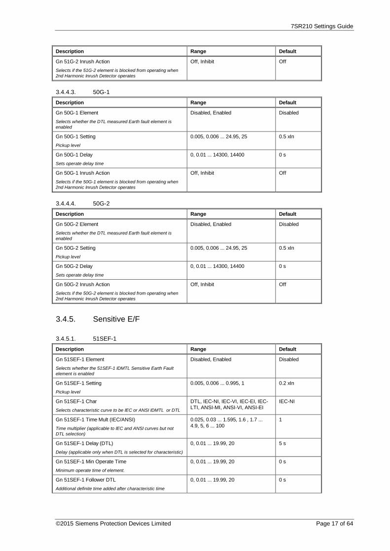
7SR210 Settings Guide
©2015 Siemens Protection Devices Limited Page 17 of 64
Description Range Default
Gn 51G-2 Inrush Action
Selects if the 51G-2 element is blocked from operating when2nd Harmonic Inrush Detector operates
Off, Inhibit Off
3.4.4.3. 50G-1
Description Range Default
Gn 50G-1 Element
Selects whether the DTL measured Earth fault element isenabled
Disabled, Enabled Disabled
Gn 50G-1 Setting
Pickup level
0.005, 0.006 ... 24.95, 25 0.5 xIn
Gn 50G-1 Delay
Sets operate delay time
0, 0.01 ... 14300, 14400 0 s
Gn 50G-1 Inrush Action
Selects if the 50G-1 element is blocked from operating when2nd Harmonic Inrush Detector operates
Off, Inhibit Off
3.4.4.4. 50G-2
Description Range Default
Gn 50G-2 Element
Selects whether the DTL measured Earth fault element isenabled
Disabled, Enabled Disabled
Gn 50G-2 Setting
Pickup level
0.005, 0.006 ... 24.95, 25 0.5 xIn
Gn 50G-2 Delay
Sets operate delay time
0, 0.01 ... 14300, 14400 0 s
Gn 50G-2 Inrush Action
Selects if the 50G-2 element is blocked from operating when2nd Harmonic Inrush Detector operates
Off, Inhibit Off
3.4.5. Sensitive E/F
3.4.5.1. 51SEF-1
Description Range Default
Gn 51SEF-1 Element
Selects whether the 51SEF-1 IDMTL Sensitive Earth Faultelement is enabled
Disabled, Enabled Disabled
Gn 51SEF-1 Setting
Pickup level
0.005, 0.006 ... 0.995, 1 0.2 xIn
Gn 51SEF-1 Char
Selects characteristic curve to be IEC or ANSI IDMTL or DTL
DTL, IEC-NI, IEC-VI, IEC-EI, IEC-LTI, ANSI-MI, ANSI-VI, ANSI-EI
IEC-NI
Gn 51SEF-1 Time Mult (IEC/ANSI)
Time multiplier (applicable to IEC and ANSI curves but notDTL selection)
0.025, 0.03 ... 1.595, 1.6 , 1.7 ...4.9, 5, 6 ... 100
1
Gn 51SEF-1 Delay (DTL)
Delay (applicable only when DTL is selected for characteristic)
0, 0.01 ... 19.99, 20 5 s
Gn 51SEF-1 Min Operate Time
Minimum operate time of element.
0, 0.01 ... 19.99, 20 0 s
Gn 51SEF-1 Follower DTL
Additional definite time added after characteristic time
0, 0.01 ... 19.99, 20 0 s

7SR210 Settings Guide
Page 18 of 64 © 2013 Siemens Protection Devices Limited
Description Range Default
Gn 51SEF-1 Reset
Selects between an ANSI decaying reset characteristic or DTLreset
(ANSI) Decaying, 0 ... 59, 60 0 s
3.4.5.2. 51SEF-2
Description Range Default
Gn 51SEF-2 Element
Selects whether the 51SEF-2 IDMTL derived Earth Faultelement is enabled
Disabled, Enabled Disabled
Gn 51SEF-2 Setting
Pickup level
0.005, 0.006 ... 0.995, 1 0.2 xIn
Gn 51SEF-2 Char
Selects characteristic curve to be IEC or ANSI IDMTL or DTL
DTL, IEC-NI, IEC-VI, IEC-EI, IEC-LTI, ANSI-MI, ANSI-VI, ANSI-EI
IEC-NI
Gn 51SEF-2 Time Mult (IEC/ANSI)
Time multiplier (applicable to IEC and ANSI curves but notDTL selection)
0.025, 0.03 ... 1.595, 1.6 , 1.7 ...4.9, 5, 6 ... 100
1
Gn 51SEF-2 Delay (DTL)
Delay (applicable only when DTL is selected for characteristic)
0, 0.01 ... 19.99, 20 5 s
Gn 51SEF-2 Min Operate Time
Minimum operate time of element.
0, 0.01 ... 19.99, 20 0 s
Gn 51SEF-2 Follower DTL
Additional definite time added after characteristic time
0, 0.01 ... 19.99, 20 0 s
Gn 51SEF-2 Reset
Selects between an ANSI decaying reset characteristic or DTLreset
(ANSI) Decaying, 0 ... 59, 60 0 s
3.4.5.3. 50SEF-1
Description Range Default
Gn 50SEF-1 Element
Selects whether the DTL measured Earth fault element isenabled
Disabled, Enabled Disabled
Gn 50SEF-1 Setting
Pickup level
0.005, 0.006 ... 4.995, 5 0.2 xIn
Gn 50SEF-1 Delay
Sets operate delay time
0, 0.01 ... 14300, 14400 0 s
3.4.5.4. 50SEF-2
Description Range Default
Gn 50SEF-2 Element
Selects whether the DTL measured Earth fault element isenabled
Disabled, Enabled Disabled
Gn 50SEF-2 Setting
Pickup level
0.005, 0.006 ... 4.995, 5 0.2 xIn
Gn 50SEF-2 Delay
Sets operate delay time
0, 0.01 ... 14300, 14400 0 s

7SR210 Settings Guide
©2015 Siemens Protection Devices Limited Page 19 of 64
3.4.6. Restricted E/F
Description Range Default
Gn 64H Element
High impedance restricted earth fault current element
Disabled, Enabled Disabled
Gn 64H Setting
Pickup level
0.005, 0.006 ... 0.945, 0.95 0.2 xIn
Gn 64H Delay
Sets operate delay time
0, 0.01 ... 14300, 14400 0 s
3.4.7. NPS Overcurrent
3.4.7.1. 46IT
Description Range Default
Gn 46IT Element
Selects whether the 46IT IDMTL/DTL negative phasesequence current element is enabled
Disabled, Enabled Disabled
Gn 46IT Setting
Pickup level
0.05, 0.06 ... 2.49, 2.5 0.25 xIn
Gn 46IT Char
Selects characteristic curve to be IEC or ANSI IDMTL or DTL
DTL, IEC-NI, IEC-VI, IEC-EI, IEC-LTI, ANSI-MI, ANSI-VI, ANSI-EI
IEC-NI
Gn 46IT Time Mult (IEC/ANSI)
Time multiplier (applicable to IEC and ANSI curves but notDTL selection)
0.025, 0.03 ... 1.595, 1.6 , 1.7 ...4.9, 5, 6 ... 100
1
Gn 46IT Delay (DTL)
Delay (applicable only when DTL is selected for characteristic)
0, 0.01 ... 19.99, 20 5 s
Gn 46IT Reset
Selects between an ANSI decaying reset characteristic or adefinite time reset
(ANSI) Decaying, 0 ... 59, 60 0 s
3.4.7.2. 46DT
Description Range Default
Gn 46DT Element
Selects whether the 46DT INST/DTL negative sequencecurrent element is enabled
Disabled, Enabled Disabled
Gn 46DT Setting
Pickup level
0.05, 0.06 ... 3.99, 4 0.1 xIn
Gn 46DT Delay
Sets operate delay time
0, 0.01 ... 14300, 14400 0.02 s

7SR210 Settings Guide
Page 20 of 64 © 2013 Siemens Protection Devices Limited
3.4.8. Under Current
3.4.8.1. 37-1
Description Range Default
Gn 37-1 Element
Phase under current element 37-1
Disabled, Enabled Disabled
Gn 37-1 Setting
Pickup level
0.05, 0.1 ... 4.95, 5 0.25 xIn
Gn 37-1 Delay
Sets operate delay time
0, 0.01 ... 14300, 14400 0 s
3.4.8.2. 37-2
Description Range Default
Gn 37-2 Element
Phase under current element 37-2
Disabled, Enabled Disabled
Gn 37-2 Setting
Pickup level
0.05, 0.1 ... 4.95, 5 0.25 xIn
Gn 37-2 Delay
Sets operate delay time
0, 0.01 ... 14300, 14400 0 s
3.4.8.3. 37G-1
Description Range Default
Gn 37G-1 Element Disabled, Enabled Disabled
Gn 37G-1 Setting 0.005, 0.006 ... 4.995, 5 0.2 xIn
Gn 37G-1 Delay 0, 0.01 ... 14300, 14400 0 s
3.4.8.4. 37G-2
Description Range Default
Gn 37G-2 Element Disabled, Enabled Disabled
Gn 37G-2 Setting 0.005, 0.006 ... 4.995, 5 0.2 xIn
Gn 37G-2 Delay 0, 0.01 ... 14300, 14400 0 s

7SR210 Settings Guide
©2015 Siemens Protection Devices Limited Page 21 of 64
3.4.9. Thermal
Description Range Default
Gn 49 Thermal Overload
Selects whether the thermal overload protection element isenabled
Disabled, Enabled Disabled
Gn 49 Overload Setting
Pickup level
0.1, 0.11 ... 2.99, 3 1.05 xIn
Gn 49 Time Constant (Minutes)
Thermal time constant
1, 1.5 ... 999.5, 1000 10 minutes
Gn 49 Capacity Alarm
Selects whether thermal capacity alarm enabled
Disabled, 50 ... 99, 100 Disabled
49 Reset Therm State
Control that allows thermal state to be manually reset
3.4.10. ARC Flash Detector
Description Range Default
Gn 50AFD
Selects whether the ARC Flash Detector element is enabled
Disabled, Enabled Disabled
Gn 50AFD Setting
Pickup level
1, 2,...10 2 xIn
3.5. Supervision
3.5.1. CB Fail
Description Range Default
Gn 50BF Element
Selects whether the Circuit Breaker Fail element is enabled
Disabled, Enabled Disabled
Gn 50BF Setting
Breaker Fail Current Pickup level. If the current falls below thislevel then the CB is deemed to have opened and the elementis reset.
0.05, 0.055 ... 1.995, 2 0.2 xIn
Gn 50BF-I4 Setting 0.005, 0.01 ... 1.995, 2 0.05 xIn
Gn 50BF-1 Delay
Delay before Circuit Breaker Fail stage 1 operates
20, 25 ... 59995, 60000 60 ms
Gn 50BF-2 Delay
Delay before Circuit Breaker Fail stage 2 operates
20, 25 ... 59995, 60000 120 ms
3.5.2. CT Supervision
Description Range Default
Gn 60CTS-I Element Disabled, Enabled Disabled
Gn 60CTS-I Setting 0.05, 0.1 ... 1.95, 2 0.05 xIn
Gn 60CTS-I Delay 0.03, 0.04 ... 14300, 14400 10 s

7SR210 Settings Guide
Page 22 of 64 © 2013 Siemens Protection Devices Limited
3.5.3. Broken Conductor
Description Range Default
Gn 46BC U/C Guard Setting 0.05, 0.1 ... 4.95, 5 0.25 xIn
Gn 46BC U/C Guarded No, Yes No
Gn 46BC Element
Selects whether the definite time broken conductor element isenabled
Disabled, Enabled Disabled
Gn 46BC Setting
NPS Current to PPS Current ratio
20, 21 ... 99, 100 20 %
Gn 46BC Delay
Sets operate delay time
0.03, 0.04 ... 14300, 14400 20 s
3.5.4. Trip CCT Supervision
Description Range Default
Gn 74TCS-1
Selects whether the trip circuit supervision element 74TCS-1is enabled
Disabled, Enabled Disabled
Gn 74TCS-1 Delay
Time delay before trip circuit supervision operates
0, 0.02 ... 59.98, 60 0.4 s
Gn 74TCS-2
Selects whether the trip circuit supervision element 74TCS-2is enabled
Disabled, Enabled Disabled
Gn 74TCS-2 Delay
Time delay before trip circuit supervision operates
0, 0.02 ... 59.98, 60 0.4 s
Gn 74TCS-3
Selects whether the trip circuit supervision element 74TCS-3is enabled
Disabled, Enabled Disabled
Gn 74TCS-3 Delay
Time delay before trip circuit supervision operates
0, 0.02 ... 59.98, 60 0.4 s
3.5.5. Close CCT Supervision
Description Range Default
Gn 74CCS-1
Selects whether the trip circuit supervision element 74CCS-1is enabled
Disabled, Enabled Disabled
Gn 74CCS-1 Delay
Time delay before trip circuit supervision operates
0, 0.02 ... 59.98, 60 0.4 s
Gn 74CCS-2
Selects whether the trip circuit supervision element 74CCS-2is enabled
Disabled, Enabled Disabled
Gn 74CCS-2 Delay
Time delay before trip circuit supervision operates
0, 0.02 ... 59.98, 60 0.4 s
Gn 74CCS-3
Selects whether the trip circuit supervision element 74CCS-3is enabled
Disabled, Enabled Disabled
Gn 74CCS-3 Delay
Time delay before trip circuit supervision operates
0, 0.02 ... 59.98, 60 0.4 s

7SR210 Settings Guide
©2015 Siemens Protection Devices Limited Page 23 of 64
3.5.6. Inrush Detector
Description Range Default
Gn 81HBL2 Element
Selects whether the phase inrush detector 81HBL2 is enabled
Disabled, Enabled Disabled
Gn 81HBL2 Bias
Selects the bias method used for magnetising inrush. Phase –Segregated, each phase blocks itself. Cross – Blocked, eachphase can block the operation of other phases. Sum - OfSquares, each phase blocks itself using the square root of thesum of squares of the 2nd harmonic.
Phase, Cross, Sum Cross
Gn 81HBL2 Setting
The magnetising inrush detector operates when the 2ndharmonic current exceeds a set percentage of the fundamentalcurrent
0.1, 0.11 ... 0.49, 0.5 0.2 xI
3.6. Control & Logic
3.6.1. Autoreclose Prot’n
Description Range Default
Gn 79 P/F Inst Trips
Selects which phase fault protection elements are classed asInstantaneous elements and start an autoreclose sequence.These will be blocked from operating during Delayedautoreclose sequences. See autoreclose section of manual fordetail of what elements can cause only Delayed protection tobe used.
Combination of ( 51-1, 51-2, 50-1,50-2 )
----
Gn 79 E/F Inst Trips
Selects which earth fault protection elements are classed asInstantaneous elements and start an autoreclose sequence.These will be blocked from operating during Delayedautoreclose sequences. See autoreclose section of manual fordetail of what elements can cause only Delayed protection tobe used.
Combination of ( 51N-1, 51N-2,50N-1, 50N-2, 51G-1, 51G-2, 50G-1, 50G-2 )
--------
Gn 79 SEF Inst Trips
Selects which sensitive earth fault protection elements areclassed as Instantaneous elements and start an autoreclosesequence. These will be blocked from operating duringDelayed autoreclose sequences. See autoreclose section ofmanual for detail of what elements can cause only Delayedprotection to be used.
Combination of ( 51SEF-1, 51SEF-2, 50SEF-1, 50SEF-2 )
----
Gn 79 P/F Delayed Trips
Selects which phase fault protection are classed as Delayedelements, any selected elements operating will start anautoreclose sequence.
Combination of ( 51-1, 51-2, 50-1,50-2 )
51-1, 51-2, 50-1,50-2
Gn 79 E/F Delayed Trips
Selects which earth fault protection are classed as Delayedelements, any selected elements operating will start anautoreclose sequence.
Combination of ( 51N-1, 51N-2,50N-1, 50N-2, 51G-1, 51G-2, 50G-1, 50G-2 )
51N-1, 51N-2,50N-1, 50N-2,51G-1, 51G-2,50G-1, 50G-2
Gn 79 SEF Delayed Trips
Selects which sensitive earth fault elements are classed asDelayed elements, any selected elements operating will startan autoreclose sequence.
Combination of ( 51SEF-1, 51SEF-2, 50SEF-1, 50SEF-2 )
51SEF-1,51SEF-2,50SEF-1,50SEF-2
Gn 79 P/F HS Trips
Selects which phase fault elements are classed as High Setelements, any selected elements operating will start anautoreclose sequence.
Combination of ( 50-1, 50-2 ) --

7SR210 Settings Guide
Page 24 of 64 © 2013 Siemens Protection Devices Limited
Description Range Default
Gn 79 E/F HS Trips
Selects which earth fault elements are classed as High Setelements, any selected elements operating will start anautoreclose sequence.
Combination of ( 50N-1, 50N-2,50G-1, 50G-2 )
----

7SR210 Settings Guide
©2015 Siemens Protection Devices Limited Page 25 of 64
3.6.2. Autoreclose Config
Description Range Default
Gn 79 Autoreclose
If disabled then all attempts to control the AR IN/OUT statuswill fail and the AR will be permanently Out Of Service. Whenenabled the AR IN/OUT state may be controlled via theCONTROL MODE menu option, via Binary Input or via localor remote communications.
Disabled, Enabled Disabled
Gn 79 Num Shots
Selects the number of auto-reclose attempts before theAutorecloser locks out
1, 2, 3, 4 1
Gn 79 Retry Enable
Selects whether the Retry close functionality is enabled
Disabled, Enabled Disabled
Gn 79 Retry Attempts
Selects the number of retries allowed per shot
0, 1, 2, 3, 4, 5, 6, 7, 8, 9, 10 1
Gn 79 Retry Interval
Time delay between retries
0, 1 ... 599, 600 60 s
Gn 79 Reclose Blocked Delay
Specifies the maximum time that the Autorecloser can beblocked before proceeding to the lockout state. (NOTE: Theblock delay timer only starts after the Deadtime.)
0, 1 ... 599, 600 60 s
Gn 79 Sequence Fail Timer
Time before lockout occurs on an incomplete reclosesequence. (i.e Trip & starter conditions have not been clearedafter Sequence Fail Time.)
0, 1 ... 599, 600 60 s
Gn 79 Sequence Co-ord
Selects whether Sequence co-ordination functionality is usedor not.
Disabled, Enabled Enabled
Gn 79 Cold Load Action
Selects whether the relay will perform Delayed Trips or notwhen Cold Load is active.
Off, Delayed Off
3.6.2.1. P/F Shots
Description Range Default
Gn 79 P/F Prot'n Trip 1
Selects whether the first phase fault trip is Instantaneous(Fast) or Delayed. When set to Delayed all P/F Inst Trips willbe Inhibited for this shot.
Inst, Delayed Inst
Gn 79 P/F Deadtime 1
Time period between the fault being cleared and the closepulse being issued
0, 0.1 ... 14300, 14400 5 s
Gn 79 P/F Prot'n Trip 2
Selects whether the second phase fault trip is Instantaneous(Fast) or Delayed. When set to Delayed all P/F Inst Trips willbe Inhibited for this shot.
Inst, Delayed Inst
Gn 79 P/F Deadtime 2
Time period between the fault being cleared and the closepulse being issued
0, 0.1 ... 14300, 14400 5 s
Gn 79 P/F Prot'n Trip 3
Selects whether the third phase fault trip is Instantaneous(Fast) or Delayed. When set to Delayed all P/F Inst Trips willbe Inhibited for this shot.
Inst, Delayed Delayed
Gn 79 P/F Deadtime 3
Time period between the fault being cleared and the closepulse being issued
0, 0.1 ... 14300, 14400 5 s
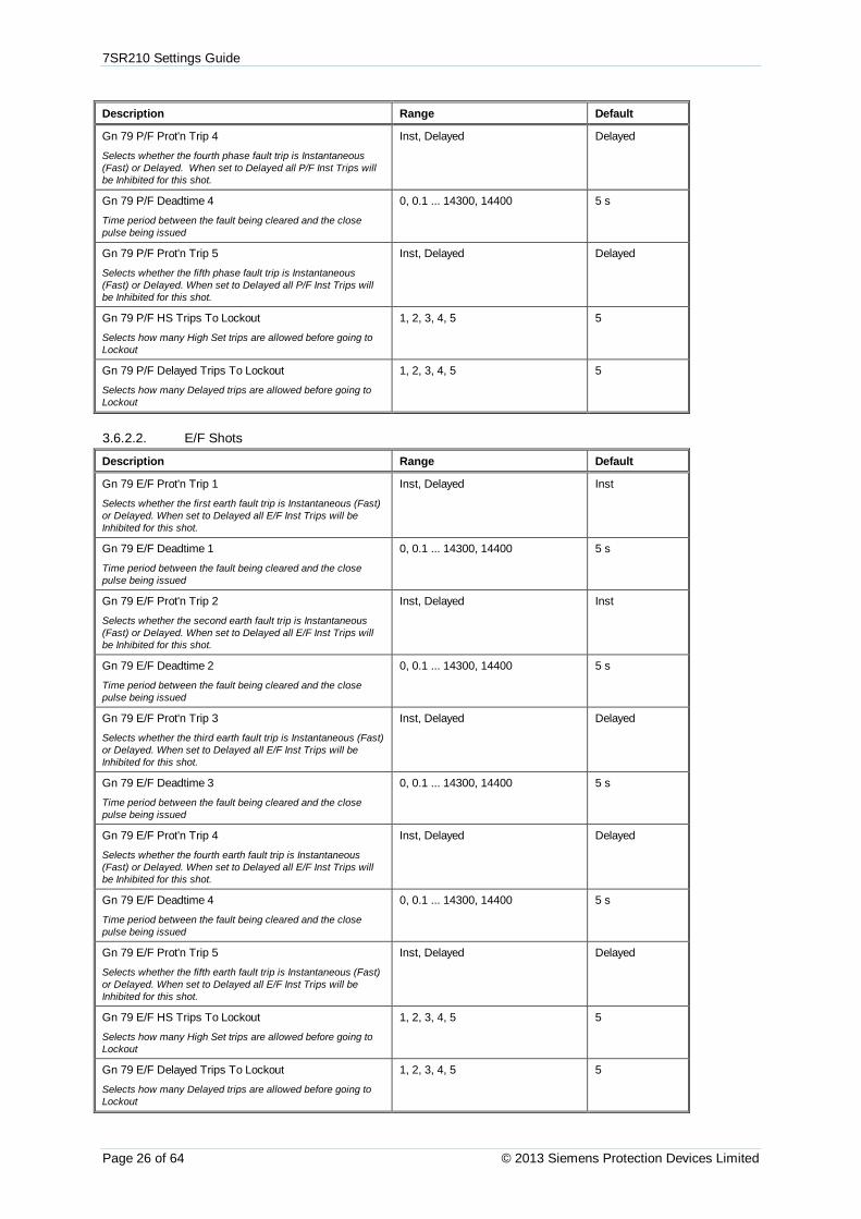
7SR210 Settings Guide
Page 26 of 64 © 2013 Siemens Protection Devices Limited
Description Range Default
Gn 79 P/F Prot'n Trip 4
Selects whether the fourth phase fault trip is Instantaneous(Fast) or Delayed. When set to Delayed all P/F Inst Trips willbe Inhibited for this shot.
Inst, Delayed Delayed
Gn 79 P/F Deadtime 4
Time period between the fault being cleared and the closepulse being issued
0, 0.1 ... 14300, 14400 5 s
Gn 79 P/F Prot'n Trip 5
Selects whether the fifth phase fault trip is Instantaneous(Fast) or Delayed. When set to Delayed all P/F Inst Trips willbe Inhibited for this shot.
Inst, Delayed Delayed
Gn 79 P/F HS Trips To Lockout
Selects how many High Set trips are allowed before going toLockout
1, 2, 3, 4, 5 5
Gn 79 P/F Delayed Trips To Lockout
Selects how many Delayed trips are allowed before going toLockout
1, 2, 3, 4, 5 5
3.6.2.2. E/F Shots
Description Range Default
Gn 79 E/F Prot'n Trip 1
Selects whether the first earth fault trip is Instantaneous (Fast)or Delayed. When set to Delayed all E/F Inst Trips will beInhibited for this shot.
Inst, Delayed Inst
Gn 79 E/F Deadtime 1
Time period between the fault being cleared and the closepulse being issued
0, 0.1 ... 14300, 14400 5 s
Gn 79 E/F Prot'n Trip 2
Selects whether the second earth fault trip is Instantaneous(Fast) or Delayed. When set to Delayed all E/F Inst Trips willbe Inhibited for this shot.
Inst, Delayed Inst
Gn 79 E/F Deadtime 2
Time period between the fault being cleared and the closepulse being issued
0, 0.1 ... 14300, 14400 5 s
Gn 79 E/F Prot'n Trip 3
Selects whether the third earth fault trip is Instantaneous (Fast)or Delayed. When set to Delayed all E/F Inst Trips will beInhibited for this shot.
Inst, Delayed Delayed
Gn 79 E/F Deadtime 3
Time period between the fault being cleared and the closepulse being issued
0, 0.1 ... 14300, 14400 5 s
Gn 79 E/F Prot'n Trip 4
Selects whether the fourth earth fault trip is Instantaneous(Fast) or Delayed. When set to Delayed all E/F Inst Trips willbe Inhibited for this shot.
Inst, Delayed Delayed
Gn 79 E/F Deadtime 4
Time period between the fault being cleared and the closepulse being issued
0, 0.1 ... 14300, 14400 5 s
Gn 79 E/F Prot'n Trip 5
Selects whether the fifth earth fault trip is Instantaneous (Fast)or Delayed. When set to Delayed all E/F Inst Trips will beInhibited for this shot.
Inst, Delayed Delayed
Gn 79 E/F HS Trips To Lockout
Selects how many High Set trips are allowed before going toLockout
1, 2, 3, 4, 5 5
Gn 79 E/F Delayed Trips To Lockout
Selects how many Delayed trips are allowed before going toLockout
1, 2, 3, 4, 5 5

7SR210 Settings Guide
©2015 Siemens Protection Devices Limited Page 27 of 64
3.6.2.3. SEF Shots
Description Range Default
Gn 79 SEF Prot'n Trip 1
Selects whether the first sensitive earth fault trip isInstantaneous or Delayed. When set to Delayed all SEF InstTrips will be Inhibited for this shot.
Inst, Delayed Inst
Gn 79 SEF Deadtime 1
Time period between the fault being cleared and the closepulse being issued
0, 0.1 ... 14300, 14400 5 s
Gn 79 SEF Prot'n Trip 2
Selects whether the second sensitive earth fault trip isInstantaneous or Delayed. When set to Delayed all SEF InstTrips will be Inhibited for this shot.
Inst, Delayed Inst
Gn 79 SEF Deadtime 2
Time period between the fault being cleared and the closepulse being issued
0, 0.1 ... 14300, 14400 5 s
Gn 79 SEF Prot'n Trip 3
Selects whether the third sensitive earth fault trip isInstantaneous or Delayed. When set to Delayed all SEF InstTrips will be Inhibited for this shot.
Inst, Delayed Delayed
Gn 79 SEF Deadtime 3
Time period between the fault being cleared and the closepulse being issued
0, 0.1 ... 14300, 14400 5 s
Gn 79 SEF Prot'n Trip 4
Selects whether the fourth sensitive earth fault trip isInstantaneous or Delayed. When set to Delayed all SEF InstTrips will be Inhibited for this shot.
Inst, Delayed Delayed
Gn 79 SEF Deadtime 4
Time period between the fault being cleared and the closepulse being issued
0, 0.1 ... 14300, 14400 5 s
Gn 79 SEF Prot'n Trip 5
Selects whether the fifth sensitive earth fault trip isInstantaneous or Delayed. When set to Delayed all SEF InstTrips will be Inhibited for this shot.
Inst, Delayed Delayed
Gn 79 SEF Delayed Trips To Lockout
Selects how many Delayed trips are allowed before going toLockout
1, 2, 3, 4, 5 5
3.6.2.4. Extern Shots
3.6.3. Manual Close
Description Range Default
Gn Line Check Trip
Selects whether line check trip is enabled, if enabled no ARsequence initiated
Disabled, Enabled Enabled
Gn P/F Line Check Trip
Selects whether a phase fault line check trip is Instantaneous(Fast) or Delayed. When set to Delayed all P/F Inst Trips willbe Inhibited for this shot.
Inst, Delayed Inst
Gn E/F Line Check Trip
Selects whether an earth fault line check trip is Instantaneousor Delayed. When set to Delayed all E/F Inst Trips will beInhibited for this shot.
Inst, Delayed Inst
Gn SEF Line Check Trip
Selects whether a sensitive earth fault line check trip isInstantaneous or Delayed. When set to Delayed all SEF InstTrips will be Inhibited for this shot.
Inst, Delayed Inst
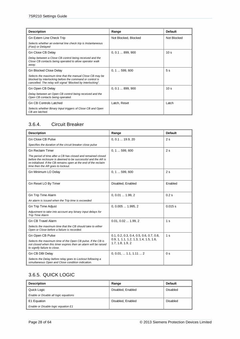
7SR210 Settings Guide
Page 28 of 64 © 2013 Siemens Protection Devices Limited
Description Range Default
Gn Extern Line Check Trip
Selects whether an external line check trip is Instantaneous(Fast) or Delayed
Not Blocked, Blocked Not Blocked
Gn Close CB Delay
Delay between a Close CB control being received and theClose CB contacts being operated to allow operator walkaway.
0, 0.1 ... 899, 900 10 s
Gn Blocked Close Delay
Selects the maximum time that the manual Close CB may beblocked by interlocking before the command or control iscancelled. The relay will signal “Blocked by Interlocking”.
0, 1 ... 599, 600 5 s
Gn Open CB Delay
Delay between an Open CB control being received and theOpen CB contacts being operated.
0, 0.1 ... 899, 900 10 s
Gn CB Controls Latched
Selects whether Binary Input triggers of Close CB and OpenCB are latched.
Latch, Reset Latch
3.6.4. Circuit Breaker
Description Range Default
Gn Close CB Pulse
Specifies the duration of the circuit breaker close pulse
0, 0.1 ... 19.9, 20 2 s
Gn Reclaim Timer
The period of time after a CB has closed and remained closedbefore the reclosure is deemed to be successful and the AR isre-initialised. If the CB remains open at the end of the reclaimtime then the AR goes to lockout.
0, 1 ... 599, 600 2 s
Gn Minimum LO Delay 0, 1 ... 599, 600 2 s
Gn Reset LO By Timer Disabled, Enabled Enabled
Gn Trip Time Alarm
An alarm is issued when the Trip time is exceeded
0, 0.01 ... 1.99, 2 0.2 s
Gn Trip Time Adjust
Adjustment to take into account any binary input delays forTrip Time Alarm
0, 0.005 ... 1.995, 2 0.015 s
Gn CB Travel Alarm
Selects the maximum time that the CB should take to eitherOpen or Close before a failure is recorded.
0.01, 0.02 ... 1.99, 2 1 s
Gn Open CB Pulse
Selects the maximum time of the Open CB pulse. If the CB isnot closed when this timer expires then an alarm will be raisedto signify failure to close.
0.1, 0.2, 0.3, 0.4, 0.5, 0.6, 0.7, 0.8,0.9, 1, 1.1, 1.2, 1.3, 1.4, 1.5, 1.6,1.7, 1.8, 1.9, 2
1 s
Gn CB DBI Delay
Selects the Delay before relay goes to Lockout following asimultaneous Open and Close condition indication.
0, 0.01, ... 1.1, 1.11 ... 2 0 s
3.6.5. QUICK LOGIC
Description Range Default
Quick Logic
Enable or Disable all logic equations
Disabled, Enabled Disabled
E1 Equation
Enable or Disable logic equation E1
Disabled, Enabled Disabled

7SR210 Settings Guide
©2015 Siemens Protection Devices Limited Page 29 of 64
Description Range Default
E1
Specify logic equations of the form En =<Operand><Operator><Operand>using thefollowing:0123456789=Digit() = Parenthesis! = NOT operation.= AND operation^ = EXCLUSIVE OR operationE(followed by adigit) = Equation numberF (Followed by a digit) = Function KeynumberI(Followed by a digit) = Binary Input numberL(Followedby a digit) = LED numberO(Followed by a digit) = output relaynumberV(Followed by a digit) =Virtual Input/Outputnumber.ExamplesMake a function key LED toggle whenfunction key is pressed (requires E1 to drive L11 in outputmatrix)E1 = F3^L11
(20 Character String)
E1 Pickup Delay
Time before equation output operates, after equation satisfied
0, 0.01 ... 14300, 14400 0 s
E1 Dropoff Delay
Time before equation output resets, after equation nolongersatisfied
0, 0.01 ... 14300, 14400 0 s
E1 Counter Target
Select number of times equation must be satisfied beforeequation output operates
1, 2 ... 998, 999 1
E1 Counter Reset Mode
Select type of counter reset mode
Off, Multi-shot, Single-shot Off
E1 Counter Reset Time
Select counter reset time
0, 0.01 ... 14300, 14400 0 s
E2 Equation
Enable or Disable logic equation E2
Disabled, Enabled Disabled
E2
Specify logic equations of the form En =<Operand><Operator><Operand>using thefollowing:0123456789=Digit() = Parenthesis! = NOT operation.= AND operation^ = EXCLUSIVE OR operationE(followed by adigit) = Equation numberF (Followed by a digit) = Function KeynumberI(Followed by a digit) = Binary Input numberL(Followedby a digit) = LED numberO(Followed by a digit) = output relaynumberV(Followed by a digit) =Virtual Input/Outputnumber.ExamplesMake a function key LED toggle whenfunction key is pressed (requires E1 to drive L11 in outputmatrix)E1 = F3^L11
(20 Character String)
E2 Pickup Delay
Time before equation output operates, after equation satisfied
0, 0.01 ... 14300, 14400 0 s
E2 Dropoff Delay
Time before equation output resets, after equation nolongersatisfied
0, 0.01 ... 14300, 14400 0 s
E2 Counter Target
Select number of times equation must be satisfied beforeequation output operates
1, 2 ... 998, 999 1
E2 Counter Reset Mode
Select type of counter reset mode
Off, Multi-shot, Single-shot Off
E2 Counter Reset Time
Select counter reset time
0, 0.01 ... 14300, 14400 0 s
E3 Equation
Enable or Disable logic equation E3
Disabled, Enabled Disabled

7SR210 Settings Guide
Page 30 of 64 © 2013 Siemens Protection Devices Limited
Description Range Default
E3
Specify logic equations of the form En =<Operand><Operator><Operand>using thefollowing:0123456789=Digit() = Parenthesis! = NOT operation.= AND operation^ = EXCLUSIVE OR operationE(followed by adigit) = Equation numberF (Followed by a digit) = Function KeynumberI(Followed by a digit) = Binary Input numberL(Followedby a digit) = LED numberO(Followed by a digit) = output relaynumberV(Followed by a digit) =Virtual Input/Outputnumber.ExamplesMake a function key LED toggle whenfunction key is pressed (requires E1 to drive L11 in outputmatrix)E1 = F3^L11
(20 Character String)
E3 Pickup Delay
Time before equation output operates, after equation satisfied
0, 0.01 ... 14300, 14400 0 s
E3 Dropoff Delay
Time before equation output resets, after equation nolongersatisfied
0, 0.01 ... 14300, 14400 0 s
E3 Counter Target
Select number of times equation must be satisfied beforeequation output operates
1, 2 ... 998, 999 1
E3 Counter Reset Mode
Select type of counter reset mode
Off, Multi-shot, Single-shot Off
E3 Counter Reset Time
Select counter reset time
0, 0.01 ... 14300, 14400 0 s
E4 Equation
Enable or Disable logic equation E4
Disabled, Enabled Disabled
E4
Specify logic equations of the form En =<Operand><Operator><Operand>using thefollowing:0123456789=Digit() = Parenthesis! = NOT operation.= AND operation^ = EXCLUSIVE OR operationE(followed by adigit) = Equation numberF (Followed by a digit) = Function KeynumberI(Followed by a digit) = Binary Input numberL(Followedby a digit) = LED numberO(Followed by a digit) = output relaynumberV(Followed by a digit) =Virtual Input/Outputnumber.ExamplesMake a function key LED toggle whenfunction key is pressed (requires E1 to drive L11 in outputmatrix)E1 = F3^L11
(20 Character String)
E4 Pickup Delay
Time before equation output operates, after equation satisfied
0, 0.01 ... 14300, 14400 0 s
E4 Dropoff Delay
Time before equation output resets, after equation nolongersatisfied
0, 0.01 ... 14300, 14400 0 s
E4 Counter Target
Select number of times equation must be satisfied beforeequation output operates
1, 2 ... 998, 999 1
E4 Counter Reset Mode
Select type of counter reset mode
Off, Multi-shot, Single-shot Off
E4 Counter Reset Time
Select counter reset time
0, 0.01 ... 14300, 14400 0 s
E5 Equation
Enable or Disable logic equation E5
Disabled, Enabled Disabled

7SR210 Settings Guide
©2015 Siemens Protection Devices Limited Page 31 of 64
Description Range Default
E5
Specify logic equations of the form En =<Operand><Operator><Operand>using thefollowing:0123456789=Digit() = Parenthesis! = NOT operation.= AND operation^ = EXCLUSIVE OR operationE(followed by adigit) = Equation numberF (Followed by a digit) = Function KeynumberI(Followed by a digit) = Binary Input numberL(Followedby a digit) = LED numberO(Followed by a digit) = output relaynumberV(Followed by a digit) =Virtual Input/Outputnumber.ExamplesMake a function key LED toggle whenfunction key is pressed (requires E1 to drive L11 in outputmatrix)E1 = F3^L11
(20 Character String)
E5 Pickup Delay
Time before equation output operates, after equation satisfied
0, 0.01 ... 14300, 14400 0 s
E5 Dropoff Delay
Time before equation output resets, after equation nolongersatisfied
0, 0.01 ... 14300, 14400 0 s
E5 Counter Target
Select number of times equation must be satisfied beforeequation output operates
1, 2 ... 998, 999 1
E5 Counter Reset Mode
Select type of counter reset mode
Off, Multi-shot, Single-shot Off
E5 Counter Reset Time
Select counter reset time
0, 0.01 ... 14300, 14400 0 s
E6 Equation
Enable or Disable logic equation E6
Disabled, Enabled Disabled
E6
Specify logic equations of the form En =<Operand><Operator><Operand>using thefollowing:0123456789=Digit() = Parenthesis! = NOT operation.= AND operation^ = EXCLUSIVE OR operationE(followed by adigit) = Equation numberF (Followed by a digit) = Function KeynumberI(Followed by a digit) = Binary Input numberL(Followedby a digit) = LED numberO(Followed by a digit) = output relaynumberV(Followed by a digit) =Virtual Input/Outputnumber.ExamplesMake a function key LED toggle whenfunction key is pressed (requires E1 to drive L11 in outputmatrix)E1 = F3^L11
(20 Character String)
E6 Pickup Delay
Time before equation output operates, after equation satisfied
0, 0.01 ... 14300, 14400 0 s
E6 Dropoff Delay
Time before equation output resets, after equation nolongersatisfied
0, 0.01 ... 14300, 14400 0 s
E6 Counter Target
Select number of times equation must be satisfied beforeequation output operates
1, 2 ... 998, 999 1
E6 Counter Reset Mode
Select type of counter reset mode
Off, Multi-shot, Single-shot Off
E6 Counter Reset Time
Select counter reset time
0, 0.01 ... 14300, 14400 0 s
E7 Equation
Enable or Disable logic equation E7
Disabled, Enabled Disabled

7SR210 Settings Guide
Page 32 of 64 © 2013 Siemens Protection Devices Limited
Description Range Default
E7
Specify logic equations of the form En =<Operand><Operator><Operand>using thefollowing:0123456789=Digit() = Parenthesis! = NOT operation.= AND operation^ = EXCLUSIVE OR operationE(followed by adigit) = Equation numberF (Followed by a digit) = Function KeynumberI(Followed by a digit) = Binary Input numberL(Followedby a digit) = LED numberO(Followed by a digit) = output relaynumberV(Followed by a digit) =Virtual Input/Outputnumber.ExamplesMake a function key LED toggle whenfunction key is pressed (requires E1 to drive L11 in outputmatrix)E1 = F3^L11
(20 Character String)
E7 Pickup Delay
Time before equation output operates, after equation satisfied
0, 0.01 ... 14300, 14400 0 s
E7 Dropoff Delay
Time before equation output resets, after equation nolongersatisfied
0, 0.01 ... 14300, 14400 0 s
E7 Counter Target
Select number of times equation must be satisfied beforeequation output operates
1, 2 ... 998, 999 1
E7 Counter Reset Mode
Select type of counter reset mode
Off, Multi-shot, Single-shot Off
E7 Counter Reset Time
Select counter reset time
0, 0.01 ... 14300, 14400 0 s
E8 Equation
Enable or Disable logic equation E8
Disabled, Enabled Disabled
E8
Specify logic equations of the form En =<Operand><Operator><Operand>using thefollowing:0123456789=Digit() = Parenthesis! = NOT operation.= AND operation^ = EXCLUSIVE OR operationE(followed by adigit) = Equation numberF (Followed by a digit) = Function KeynumberI(Followed by a digit) = Binary Input numberL(Followedby a digit) = LED numberO(Followed by a digit) = output relaynumberV(Followed by a digit) =Virtual Input/Outputnumber.ExamplesMake a function key LED toggle whenfunction key is pressed (requires E1 to drive L11 in outputmatrix)E1 = F3^L11
(20 Character String)
E8 Pickup Delay
Time before equation output operates, after equation satisfied
0, 0.01 ... 14300, 14400 0 s
E8 Dropoff Delay
Time before equation output resets, after equation nolongersatisfied
0, 0.01 ... 14300, 14400 0 s
E8 Counter Target
Select number of times equation must be satisfied beforeequation output operates
1, 2 ... 998, 999 1
E8 Counter Reset Mode
Select type of counter reset mode
Off, Multi-shot, Single-shot Off
E8 Counter Reset Time
Select counter reset time
0, 0.01 ... 14300, 14400 0 s
E9 Equation
Enable or Disable logic equation E9
Disabled, Enabled Disabled

7SR210 Settings Guide
©2015 Siemens Protection Devices Limited Page 33 of 64
Description Range Default
E9
Specify logic equations of the form En =<Operand><Operator><Operand>using thefollowing:0123456789=Digit() = Parenthesis! = NOT operation.= AND operation^ = EXCLUSIVE OR operationE(followed by adigit) = Equation numberF (Followed by a digit) = Function KeynumberI(Followed by a digit) = Binary Input numberL(Followedby a digit) = LED numberO(Followed by a digit) = output relaynumberV(Followed by a digit) =Virtual Input/Outputnumber.ExamplesMake a function key LED toggle whenfunction key is pressed (requires E1 to drive L11 in outputmatrix)E1 = F3^L11
(20 Character String)
E9 Pickup Delay
Time before equation output operates, after equation satisfied
0, 0.01 ... 14300, 14400 0 s
E9 Dropoff Delay
Time before equation output resets, after equation nolongersatisfied
0, 0.01 ... 14300, 14400 0 s
E9 Counter Target
Select number of times equation must be satisfied beforeequation output operates
1, 2 ... 998, 999 1
E9 Counter Reset Mode
Select type of counter reset mode
Off, Multi-shot, Single-shot Off
E9 Counter Reset Time
Select counter reset time
0, 0.01 ... 14300, 14400 0 s
E10 Equation
Enable or Disable logic equation E10
Disabled, Enabled Disabled
E10
Specify logic equations of the form En =<Operand><Operator><Operand>using thefollowing:0123456789=Digit() = Parenthesis! = NOT operation.= AND operation^ = EXCLUSIVE OR operationE(followed by adigit) = Equation numberF (Followed by a digit) = Function KeynumberI(Followed by a digit) = Binary Input numberL(Followedby a digit) = LED numberO(Followed by a digit) = output relaynumberV(Followed by a digit) =Virtual Input/Outputnumber.ExamplesMake a function key LED toggle whenfunction key is pressed (requires E1 to drive L11 in outputmatrix)E1 = F3^L11
(20 Character String)
E10 Pickup Delay
Time before equation output operates, after equation satisfied
0, 0.01 ... 14300, 14400 0 s
E10 Dropoff Delay
Time before equation output resets, after equation nolongersatisfied
0, 0.01 ... 14300, 14400 0 s
E10 Counter Target
Select number of times equation must be satisfied beforeequation output operates
1, 2 ... 998, 999 1
E10 Counter Reset Mode
Select type of counter reset mode
Off, Multi-shot, Single-shot Off
E10 Counter Reset Time
Select counter reset time
0, 0.01 ... 14300, 14400 0 s
E11 Equation
Enable or Disable logic equation E11
Disabled, Enabled Disabled

7SR210 Settings Guide
Page 34 of 64 © 2013 Siemens Protection Devices Limited
Description Range Default
E11
Specify logic equations of the form En =<Operand><Operator><Operand>using thefollowing:0123456789=Digit() = Parenthesis! = NOT operation.= AND operation^ = EXCLUSIVE OR operationE(followed by adigit) = Equation numberF (Followed by a digit) = Function KeynumberI(Followed by a digit) = Binary Input numberL(Followedby a digit) = LED numberO(Followed by a digit) = output relaynumberV(Followed by a digit) =Virtual Input/Outputnumber.ExamplesMake a function key LED toggle whenfunction key is pressed (requires E1 to drive L11 in outputmatrix)E1 = F3^L11
(20 Character String)
E11 Pickup Delay
Time before equation output operates, after equation satisfied
0, 0.01 ... 14300, 14400 0 s
E11 Dropoff Delay
Time before equation output resets, after equation nolongersatisfied
0, 0.01 ... 14300, 14400 0 s
E11 Counter Target
Select number of times equation must be satisfied beforeequation output operates
1, 2 ... 998, 999 1
E11 Counter Reset Mode
Select type of counter reset mode
Off, Multi-shot, Single-shot Off
E11 Counter Reset Time
Select counter reset time
0, 0.01 ... 14300, 14400 0 s
E12 Equation
Enable or Disable logic equation E12
Disabled, Enabled Disabled
E12
Specify logic equations of the form En =<Operand><Operator><Operand>using thefollowing:0123456789=Digit() = Parenthesis! = NOT operation.= AND operation^ = EXCLUSIVE OR operationE(followed by adigit) = Equation numberF (Followed by a digit) = Function KeynumberI(Followed by a digit) = Binary Input numberL(Followedby a digit) = LED numberO(Followed by a digit) = output relaynumberV(Followed by a digit) =Virtual Input/Outputnumber.ExamplesMake a function key LED toggle whenfunction key is pressed (requires E1 to drive L11 in outputmatrix)E1 = F3^L11
(20 Character String)
E12 Pickup Delay
Time before equation output operates, after equation satisfied
0, 0.01 ... 14300, 14400 0 s
E12 Dropoff Delay
Time before equation output resets, after equation nolongersatisfied
0, 0.01 ... 14300, 14400 0 s
E12 Counter Target
Select number of times equation must be satisfied beforeequation output operates
1, 2 ... 998, 999 1
E12 Counter Reset Mode
Select type of counter reset mode
Off, Multi-shot, Single-shot Off
E12 Counter Reset Time
Select counter reset time
0, 0.01 ... 14300, 14400 0 s
E13 Equation
Enable or Disable logic equation E13
Disabled, Enabled Disabled

7SR210 Settings Guide
©2015 Siemens Protection Devices Limited Page 35 of 64
Description Range Default
E13
Specify logic equations of the form En =<Operand><Operator><Operand>using thefollowing:0123456789=Digit() = Parenthesis! = NOT operation.= AND operation^ = EXCLUSIVE OR operationE(followed by adigit) = Equation numberF (Followed by a digit) = Function KeynumberI(Followed by a digit) = Binary Input numberL(Followedby a digit) = LED numberO(Followed by a digit) = output relaynumberV(Followed by a digit) =Virtual Input/Outputnumber.ExamplesMake a function key LED toggle whenfunction key is pressed (requires E1 to drive L11 in outputmatrix)E1 = F3^L11
(20 Character String)
E13 Pickup Delay
Time before equation output operates, after equation satisfied
0, 0.01 ... 14300, 14400 0 s
E13 Dropoff Delay
Time before equation output resets, after equation nolongersatisfied
0, 0.01 ... 14300, 14400 0 s
E13 Counter Target
Select number of times equation must be satisfied beforeequation output operates
1, 2 ... 998, 999 1
E13 Counter Reset Mode
Select type of counter reset mode
Off, Multi-shot, Single-shot Off
E13 Counter Reset Time
Select counter reset time
0, 0.01 ... 14300, 14400 0 s
E14 Equation
Enable or Disable logic equation E14
Disabled, Enabled Disabled
E14
Specify logic equations of the form En =<Operand><Operator><Operand>using thefollowing:0123456789=Digit() = Parenthesis! = NOT operation.= AND operation^ = EXCLUSIVE OR operationE(followed by adigit) = Equation numberF (Followed by a digit) = Function KeynumberI(Followed by a digit) = Binary Input numberL(Followedby a digit) = LED numberO(Followed by a digit) = output relaynumberV(Followed by a digit) =Virtual Input/Outputnumber.ExamplesMake a function key LED toggle whenfunction key is pressed (requires E1 to drive L11 in outputmatrix)E1 = F3^L11
(20 Character String)
E14 Pickup Delay
Time before equation output operates, after equation satisfied
0, 0.01 ... 14300, 14400 0 s
E14 Dropoff Delay
Time before equation output resets, after equation nolongersatisfied
0, 0.01 ... 14300, 14400 0 s
E14 Counter Target
Select number of times equation must be satisfied beforeequation output operates
1, 2 ... 998, 999 1
E14 Counter Reset Mode
Select type of counter reset mode
Off, Multi-shot, Single-shot Off
E14 Counter Reset Time
Select counter reset time
0, 0.01 ... 14300, 14400 0 s
E15 Equation
Enable or Disable logic equation E15
Disabled, Enabled Disabled

7SR210 Settings Guide
Page 36 of 64 © 2013 Siemens Protection Devices Limited
Description Range Default
E15
Specify logic equations of the form En =<Operand><Operator><Operand>using thefollowing:0123456789=Digit() = Parenthesis! = NOT operation.= AND operation^ = EXCLUSIVE OR operationE(followed by adigit) = Equation numberF (Followed by a digit) = Function KeynumberI(Followed by a digit) = Binary Input numberL(Followedby a digit) = LED numberO(Followed by a digit) = output relaynumberV(Followed by a digit) =Virtual Input/Outputnumber.ExamplesMake a function key LED toggle whenfunction key is pressed (requires E1 to drive L11 in outputmatrix)E1 = F3^L11
(20 Character String)
E15 Pickup Delay
Time before equation output operates, after equation satisfied
0, 0.01 ... 14300, 14400 0 s
E15 Dropoff Delay
Time before equation output resets, after equation nolongersatisfied
0, 0.01 ... 14300, 14400 0 s
E15 Counter Target
Select number of times equation must be satisfied beforeequation output operates
1, 2 ... 998, 999 1
E15 Counter Reset Mode
Select type of counter reset mode
Off, Multi-shot, Single-shot Off
E15 Counter Reset Time
Select counter reset time
0, 0.01 ... 14300, 14400 0 s
E16 Equation
Enable or Disable logic equation E16
Disabled, Enabled Disabled
E16
Specify logic equations of the form En =<Operand><Operator><Operand>using thefollowing:0123456789=Digit() = Parenthesis! = NOT operation.= AND operation^ = EXCLUSIVE OR operationE(followed by adigit) = Equation numberF (Followed by a digit) = Function KeynumberI(Followed by a digit) = Binary Input numberL(Followedby a digit) = LED numberO(Followed by a digit) = output relaynumberV(Followed by a digit) =Virtual Input/Outputnumber.ExamplesMake a function key LED toggle whenfunction key is pressed (requires E1 to drive L11 in outputmatrix)E1 = F3^L11
(20 Character String)
E16 Pickup Delay
Time before equation output operates, after equation satisfied
0, 0.01 ... 14300, 14400 0 s
E16 Dropoff Delay
Time before equation output resets, after equation nolongersatisfied
0, 0.01 ... 14300, 14400 0 s
E16 Counter Target
Select number of times equation must be satisfied beforeequation output operates
1, 2 ... 998, 999 1
E16 Counter Reset Mode
Select type of counter reset mode
Off, Multi-shot, Single-shot Off
E16 Counter Reset Time
Select counter reset time
0, 0.01 ... 14300, 14400 0 s

7SR210 Settings Guide
©2015 Siemens Protection Devices Limited Page 37 of 64
3.7. Input Config
3.7.1. Input Matrix
Description Range Default
Inhibit Cold Load Combination of ( BI1, BI2, BI3, BI4,BI5, BI6, BI7, BI8, BI9, V1, V2, V3,V4, V5, V6, V7, V8, V9, V10, V11,V12, V13, V14, V15, V16 )
-------------------------
Inhibit 51-1
Selects which inputs inhibit the 51-1 element
Combination of ( BI1, BI2, BI3, BI4,BI5, BI6, BI7, BI8, BI9, V1, V2, V3,V4, V5, V6, V7, V8, V9, V10, V11,V12, V13, V14, V15, V16 )
-------------------------
Inhibit 51-2
Selects which inputs inhibit the 51-2 element
Combination of ( BI1, BI2, BI3, BI4,BI5, BI6, BI7, BI8, BI9, V1, V2, V3,V4, V5, V6, V7, V8, V9, V10, V11,V12, V13, V14, V15, V16 )
-------------------------
Inhibit 50-1
Selects which inputs inhibit the 50-1 element
Combination of ( BI1, BI2, BI3, BI4,BI5, BI6, BI7, BI8, BI9, V1, V2, V3,V4, V5, V6, V7, V8, V9, V10, V11,V12, V13, V14, V15, V16 )
-------------------------
Inhibit 50-2
Selects which inputs inhibit the 50-2 element
Combination of ( BI1, BI2, BI3, BI4,BI5, BI6, BI7, BI8, BI9, V1, V2, V3,V4, V5, V6, V7, V8, V9, V10, V11,V12, V13, V14, V15, V16 )
-------------------------
Inhibit 51N-1
Selects which inputs inhibit the 51N-1 element
Combination of ( BI1, BI2, BI3, BI4,BI5, BI6, BI7, BI8, BI9, V1, V2, V3,V4, V5, V6, V7, V8, V9, V10, V11,V12, V13, V14, V15, V16 )
-------------------------
Inhibit 51N-2
Selects which inputs inhibit the 51N-2 element
Combination of ( BI1, BI2, BI3, BI4,BI5, BI6, BI7, BI8, BI9, V1, V2, V3,V4, V5, V6, V7, V8, V9, V10, V11,V12, V13, V14, V15, V16 )
-------------------------
Inhibit 50N-1
Selects which inputs inhibit the 50N-1 element
Combination of ( BI1, BI2, BI3, BI4,BI5, BI6, BI7, BI8, BI9, V1, V2, V3,V4, V5, V6, V7, V8, V9, V10, V11,V12, V13, V14, V15, V16 )
-------------------------
Inhibit 50N-2
Selects which inputs inhibit the 50N-2 element
Combination of ( BI1, BI2, BI3, BI4,BI5, BI6, BI7, BI8, BI9, V1, V2, V3,V4, V5, V6, V7, V8, V9, V10, V11,V12, V13, V14, V15, V16 )
-------------------------
Inhibit 51G-1
Selects which inputs inhibit the 51G-1 element
Combination of ( BI1, BI2, BI3, BI4,BI5, BI6, BI7, BI8, BI9, V1, V2, V3,V4, V5, V6, V7, V8, V9, V10, V11,V12, V13, V14, V15, V16 )
-------------------------
Inhibit 51G-2
Selects which inputs inhibit the 51G-2 element
Combination of ( BI1, BI2, BI3, BI4,BI5, BI6, BI7, BI8, BI9, V1, V2, V3,V4, V5, V6, V7, V8, V9, V10, V11,V12, V13, V14, V15, V16 )
-------------------------
Inhibit 50G-1
Selects which inputs inhibit the 50G-1 element
Combination of ( BI1, BI2, BI3, BI4,BI5, BI6, BI7, BI8, BI9, V1, V2, V3,V4, V5, V6, V7, V8, V9, V10, V11,V12, V13, V14, V15, V16 )
-------------------------
Inhibit 50G-2
Selects which inputs inhibit the 50G-2 element
Combination of ( BI1, BI2, BI3, BI4,BI5, BI6, BI7, BI8, BI9, V1, V2, V3,V4, V5, V6, V7, V8, V9, V10, V11,V12, V13, V14, V15, V16 )
-------------------------
Inhibit 51SEF-1
Selects which inputs inhibit the 51SEF-1 element
Combination of ( BI1, BI2, BI3, BI4,BI5, BI6, BI7, BI8, BI9, V1, V2, V3,V4, V5, V6, V7, V8, V9, V10, V11,V12, V13, V14, V15, V16 )
-------------------------

7SR210 Settings Guide
Page 38 of 64 © 2013 Siemens Protection Devices Limited
Description Range Default
Inhibit 51SEF-2
Selects which inputs inhibit the 51SEF-2 element
Combination of ( BI1, BI2, BI3, BI4,BI5, BI6, BI7, BI8, BI9, V1, V2, V3,V4, V5, V6, V7, V8, V9, V10, V11,V12, V13, V14, V15, V16 )
-------------------------
Inhibit 50SEF-1
Selects which inputs inhibit the 50SEF-1 element
Combination of ( BI1, BI2, BI3, BI4,BI5, BI6, BI7, BI8, BI9, V1, V2, V3,V4, V5, V6, V7, V8, V9, V10, V11,V12, V13, V14, V15, V16 )
-------------------------
Inhibit 50SEF-2
Selects which inputs inhibit the 50SEF-2 element
Combination of ( BI1, BI2, BI3, BI4,BI5, BI6, BI7, BI8, BI9, V1, V2, V3,V4, V5, V6, V7, V8, V9, V10, V11,V12, V13, V14, V15, V16 )
-------------------------
Inhibit 64H
Selects which inputs inhibit the 64H element
Combination of ( BI1, BI2, BI3, BI4,BI5, BI6, BI7, BI8, BI9, V1, V2, V3,V4, V5, V6, V7, V8, V9, V10, V11,V12, V13, V14, V15, V16 )
-------------------------
Inhibit 46IT
Selects which inputs inhibit the 46IT element
Combination of ( BI1, BI2, BI3, BI4,BI5, BI6, BI7, BI8, BI9, V1, V2, V3,V4, V5, V6, V7, V8, V9, V10, V11,V12, V13, V14, V15, V16 )
-------------------------
Inhibit 46DT
Selects which inputs inhibit the 46DT element
Combination of ( BI1, BI2, BI3, BI4,BI5, BI6, BI7, BI8, BI9, V1, V2, V3,V4, V5, V6, V7, V8, V9, V10, V11,V12, V13, V14, V15, V16 )
-------------------------
Inhibit 37-1
Selects which inputs inhibit the 37-1 element
Combination of ( BI1, BI2, BI3, BI4,BI5, BI6, BI7, BI8, BI9, V1, V2, V3,V4, V5, V6, V7, V8, V9, V10, V11,V12, V13, V14, V15, V16 )
-------------------------
Inhibit 37-2
Selects which inputs inhibit the 37-2 element
Combination of ( BI1, BI2, BI3, BI4,BI5, BI6, BI7, BI8, BI9, V1, V2, V3,V4, V5, V6, V7, V8, V9, V10, V11,V12, V13, V14, V15, V16 )
-------------------------
Inhibit 37G-1 Combination of ( BI1, BI2, BI3, BI4,BI5, BI6, BI7, BI8, BI9, V1, V2, V3,V4, V5, V6, V7, V8, V9, V10, V11,V12, V13, V14, V15, V16 )
-------------------------
Inhibit 37G-2 Combination of ( BI1, BI2, BI3, BI4,BI5, BI6, BI7, BI8, BI9, V1, V2, V3,V4, V5, V6, V7, V8, V9, V10, V11,V12, V13, V14, V15, V16 )
-------------------------
Inhibit 49
Selects which inputs inhibit the 49 thermal element
Combination of ( BI1, BI2, BI3, BI4,BI5, BI6, BI7, BI8, BI9, V1, V2, V3,V4, V5, V6, V7, V8, V9, V10, V11,V12, V13, V14, V15, V16 )
-------------------------
Reset 49
Selects which inputs resets the 49 thermal model element
Combination of ( BI1, BI2, BI3, BI4,BI5, BI6, BI7, BI8, BI9, V1, V2, V3,V4, V5, V6, V7, V8, V9, V10, V11,V12, V13, V14, V15, V16 )
-------------------------
Inhibit 60CTS-I Combination of ( BI1, BI2, BI3, BI4,BI5, BI6, BI7, BI8, BI9, V1, V2, V3,V4, V5, V6, V7, V8, V9, V10, V11,V12, V13, V14, V15, V16 )
-------------------------
Inhibit 46BC
Selects which inputs inhibit the 46 Broken Conductor element
Combination of ( BI1, BI2, BI3, BI4,BI5, BI6, BI7, BI8, BI9, V1, V2, V3,V4, V5, V6, V7, V8, V9, V10, V11,V12, V13, V14, V15, V16 )
-------------------------
74TCS-1
Selects which inputs are monitoring trip circuits
Combination of ( BI1, BI2, BI3, BI4,BI5, BI6, BI7, BI8, BI9, V1, V2, V3,V4, V5, V6, V7, V8, V9, V10, V11,V12, V13, V14, V15, V16 )
-------------------------
74TCS-2
As Above
Combination of ( BI1, BI2, BI3, BI4,BI5, BI6, BI7, BI8, BI9, V1, V2, V3,V4, V5, V6, V7, V8, V9, V10, V11,V12, V13, V14, V15, V16 )
-------------------------

7SR210 Settings Guide
©2015 Siemens Protection Devices Limited Page 39 of 64
Description Range Default
74TCS-3
As Above
Combination of ( BI1, BI2, BI3, BI4,BI5, BI6, BI7, BI8, BI9, V1, V2, V3,V4, V5, V6, V7, V8, V9, V10, V11,V12, V13, V14, V15, V16 )
-------------------------
74CCS-1
Selects which inputs are monitoring trip circuits
Combination of ( BI1, BI2, BI3, BI4,BI5, BI6, BI7, BI8, BI9, V1, V2, V3,V4, V5, V6, V7, V8, V9, V10, V11,V12, V13, V14, V15, V16 )
-------------------------
74CCS-2
As Above
Combination of ( BI1, BI2, BI3, BI4,BI5, BI6, BI7, BI8, BI9, V1, V2, V3,V4, V5, V6, V7, V8, V9, V10, V11,V12, V13, V14, V15, V16 )
-------------------------
74CCS-3
As Above
Combination of ( BI1, BI2, BI3, BI4,BI5, BI6, BI7, BI8, BI9, V1, V2, V3,V4, V5, V6, V7, V8, V9, V10, V11,V12, V13, V14, V15, V16 )
-------------------------
Trig Trip Contacts
Selects which inputs will trigger the Trip contacts
Combination of ( BI1, BI2, BI3, BI4,BI5, BI6, BI7, BI8, BI9, V1, V2, V3,V4, V5, V6, V7, V8, V9, V10, V11,V12, V13, V14, V15, V16 )
-------------------------
Inhibit 50BF
Selects which inputs inhibit the 50BF element
Combination of ( BI1, BI2, BI3, BI4,BI5, BI6, BI7, BI8, BI9, V1, V2, V3,V4, V5, V6, V7, V8, V9, V10, V11,V12, V13, V14, V15, V16 )
-------------------------
50BF CB Faulty
Selects which input bypasses the 50BF timer due to a fault CB
Combination of ( BI1, BI2, BI3, BI4,BI5, BI6, BI7, BI8, BI9, V1, V2, V3,V4, V5, V6, V7, V8, V9, V10, V11,V12, V13, V14, V15, V16 )
-------------------------
50BF Mech Trip
Selects which input allows a mechanical trip to start the 50BFelement
Combination of ( BI1, BI2, BI3, BI4,BI5, BI6, BI7, BI8, BI9, V1, V2, V3,V4, V5, V6, V7, V8, V9, V10, V11,V12, V13, V14, V15, V16 )
-------------------------
50BF Ext Trip
Selects which inputs can also start the 50BF element
Combination of ( BI1, BI2, BI3, BI4,BI5, BI6, BI7, BI8, BI9, V1, V2, V3,V4, V5, V6, V7, V8, V9, V10, V11,V12, V13, V14, V15, V16 )
-------------------------
Reset CB Total Trip
Selects which inputs Reset the CB Total Trip count
Combination of ( BI1, BI2, BI3, BI4,BI5, BI6, BI7, BI8, BI9, V1, V2, V3,V4, V5, V6, V7, V8, V9, V10, V11,V12, V13, V14, V15, V16 )
-------------------------
Reset CB Delta Trip
Selects which inputs Reset the CB Delta Trip count
Combination of ( BI1, BI2, BI3, BI4,BI5, BI6, BI7, BI8, BI9, V1, V2, V3,V4, V5, V6, V7, V8, V9, V10, V11,V12, V13, V14, V15, V16 )
-------------------------
Reset ARBlock Count
Selects which inputs Reset the AR Block count
Combination of ( BI1, BI2, BI3, BI4,BI5, BI6, BI7, BI8, BI9, V1, V2, V3,V4, V5, V6, V7, V8, V9, V10, V11,V12, V13, V14, V15, V16 )
-------------------------
Reset Freq Ops Count
Selects which inputs Reset the Frequent Ops count
Combination of ( BI1, BI2, BI3, BI4,BI5, BI6, BI7, BI8, BI9, V1, V2, V3,V4, V5, V6, V7, V8, V9, V10, V11,V12, V13, V14, V15, V16 )
-------------------------
Reset I^2t CB Wear
Selects which inputs Reset the I^2t CB Wear element
Combination of ( BI1, BI2, BI3, BI4,BI5, BI6, BI7, BI8, BI9, V1, V2, V3,V4, V5, V6, V7, V8, V9, V10, V11,V12, V13, V14, V15, V16 )
-------------------------
Trigger I^2t CB Wear
Selects which inputs will cause an external trigger of the I^2tCB Wear element
Combination of ( BI1, BI2, BI3, BI4,BI5, BI6, BI7, BI8, BI9, V1, V2, V3,V4, V5, V6, V7, V8, V9, V10, V11,V12, V13, V14, V15, V16 )
-------------------------
Reset Trip Time
Selects which inputs will reset the CB trip time alarm
Combination of ( BI1, BI2, BI3, BI4,BI5, BI6, BI7, BI8, BI9, V1, V2, V3,V4, V5, V6, V7, V8, V9, V10, V11,V12, V13, V14, V15, V16 )
-------------------------

7SR210 Settings Guide
Page 40 of 64 © 2013 Siemens Protection Devices Limited
Description Range Default
General Alarm 1
Selects which inputs will activate the General Alarm 1 text
Combination of ( BI1, BI2, BI3, BI4,BI5, BI6, BI7, BI8, BI9, V1, V2, V3,V4, V5, V6, V7, V8, V9, V10, V11,V12, V13, V14, V15, V16 )
-------------------------
General Alarm 2
Selects which inputs will activate the General Alarm 2 text
Combination of ( BI1, BI2, BI3, BI4,BI5, BI6, BI7, BI8, BI9, V1, V2, V3,V4, V5, V6, V7, V8, V9, V10, V11,V12, V13, V14, V15, V16 )
-------------------------
General Alarm 3
Selects which inputs will activate the General Alarm 3 text
Combination of ( BI1, BI2, BI3, BI4,BI5, BI6, BI7, BI8, BI9, V1, V2, V3,V4, V5, V6, V7, V8, V9, V10, V11,V12, V13, V14, V15, V16 )
-------------------------
General Alarm 4
Selects which inputs will activate the General Alarm 4 text
Combination of ( BI1, BI2, BI3, BI4,BI5, BI6, BI7, BI8, BI9, V1, V2, V3,V4, V5, V6, V7, V8, V9, V10, V11,V12, V13, V14, V15, V16 )
-------------------------
General Alarm 5
Selects which inputs will activate the General Alarm 5 text
Combination of ( BI1, BI2, BI3, BI4,BI5, BI6, BI7, BI8, BI9, V1, V2, V3,V4, V5, V6, V7, V8, V9, V10, V11,V12, V13, V14, V15, V16 )
-------------------------
General Alarm 6
Selects which inputs will activate the General Alarm 6 text
Combination of ( BI1, BI2, BI3, BI4,BI5, BI6, BI7, BI8, BI9, V1, V2, V3,V4, V5, V6, V7, V8, V9, V10, V11,V12, V13, V14, V15, V16 )
-------------------------
General Alarm 7
Selects which inputs will activate the General Alarm 7 text
Combination of ( BI1, BI2, BI3, BI4,BI5, BI6, BI7, BI8, BI9, V1, V2, V3,V4, V5, V6, V7, V8, V9, V10, V11,V12, V13, V14, V15, V16 )
-------------------------
General Alarm 8
Selects which inputs will activate the General Alarm 8 text
Combination of ( BI1, BI2, BI3, BI4,BI5, BI6, BI7, BI8, BI9, V1, V2, V3,V4, V5, V6, V7, V8, V9, V10, V11,V12, V13, V14, V15, V16 )
-------------------------
General Alarm 9
Selects which inputs will activate the General Alarm 9 text
Combination of ( BI1, BI2, BI3, BI4,BI5, BI6, BI7, BI8, BI9, V1, V2, V3,V4, V5, V6, V7, V8, V9, V10, V11,V12, V13, V14, V15, V16 )
-------------------------
General Alarm 10
Selects which inputs will activate the General Alarm 10 text
Combination of ( BI1, BI2, BI3, BI4,BI5, BI6, BI7, BI8, BI9, V1, V2, V3,V4, V5, V6, V7, V8, V9, V10, V11,V12, V13, V14, V15, V16 )
-------------------------
General Alarm 11
Selects which inputs will activate the General Alarm 11 text
Combination of ( BI1, BI2, BI3, BI4,BI5, BI6, BI7, BI8, BI9, V1, V2, V3,V4, V5, V6, V7, V8, V9, V10, V11,V12, V13, V14, V15, V16 )
-------------------------
General Alarm 12
Selects which inputs will activate the General Alarm 12 text
Combination of ( BI1, BI2, BI3, BI4,BI5, BI6, BI7, BI8, BI9, V1, V2, V3,V4, V5, V6, V7, V8, V9, V10, V11,V12, V13, V14, V15, V16 )
-------------------------
CB Open
Selects which inputs are connected to the circuit breaker opencontacts
Combination of ( BI1, BI2, BI3, BI4,BI5, BI6, BI7, BI8, BI9, V1, V2, V3,V4, V5, V6, V7, V8, V9, V10, V11,V12, V13, V14, V15, V16 )
-------------------------
CB Closed
Selects which inputs are connected to the circuit breakerclosed contacts
Combination of ( BI1, BI2, BI3, BI4,BI5, BI6, BI7, BI8, BI9, V1, V2, V3,V4, V5, V6, V7, V8, V9, V10, V11,V12, V13, V14, V15, V16 )
-------------------------
Reset Demand
Selects which inputs will rest the Demand elements.
Combination of ( BI1, BI2, BI3, BI4,BI5, BI6, BI7, BI8, BI9, V1, V2, V3,V4, V5, V6, V7, V8, V9, V10, V11,V12, V13, V14, V15, V16 )
-------------------------
Close CB
Selects which inputs will issue a close to the circuit breaker.
Combination of ( BI1, BI2, BI3, BI4,BI5, BI6, BI7, BI8, BI9, V1, V2, V3,V4, V5, V6, V7, V8, V9, V10, V11,V12, V13, V14, V15, V16 )
-------------------------

7SR210 Settings Guide
©2015 Siemens Protection Devices Limited Page 41 of 64
Description Range Default
Block Close CB
Selects which inputs will block the manual closing of the circuitbreaker.
Combination of ( BI1, BI2, BI3, BI4,BI5, BI6, BI7, BI8, BI9, V1, V2, V3,V4, V5, V6, V7, V8, V9, V10, V11,V12, V13, V14, V15, V16 )
-------------------------
Open CB
Selects which inputs will issue an open to the circuit breaker.
Combination of ( BI1, BI2, BI3, BI4,BI5, BI6, BI7, BI8, BI9, V1, V2, V3,V4, V5, V6, V7, V8, V9, V10, V11,V12, V13, V14, V15, V16 )
-------------------------
79 Out
Selects which inputs will switch the Auto-recloser out ofservice
Combination of ( BI1, BI2, BI3, BI4,BI5, BI6, BI7, BI8, BI9, V1, V2, V3,V4, V5, V6, V7, V8, V9, V10, V11,V12, V13, V14, V15, V16 )
-------------------------
79 In
Selects which inputs will switch the Auto-recloser in service
Combination of ( BI1, BI2, BI3, BI4,BI5, BI6, BI7, BI8, BI9, V1, V2, V3,V4, V5, V6, V7, V8, V9, V10, V11,V12, V13, V14, V15, V16 )
-------------------------
79 Trip & Reclose
Selects which inputs will trigger a trip & reclose
Combination of ( BI1, BI2, BI3, BI4,BI5, BI6, BI7, BI8, BI9, V1, V2, V3,V4, V5, V6, V7, V8, V9, V10, V11,V12, V13, V14, V15, V16 )
-------------------------
79 Trip & Lockout
Selects which inputs will trigger a trip & lockout
Combination of ( BI1, BI2, BI3, BI4,BI5, BI6, BI7, BI8, BI9, V1, V2, V3,V4, V5, V6, V7, V8, V9, V10, V11,V12, V13, V14, V15, V16 )
-------------------------
79 Ext Trip
Selects which input will start the external an Auto-relosesequence
Combination of ( BI1, BI2, BI3, BI4,BI5, BI6, BI7, BI8, BI9, V1, V2, V3,V4, V5, V6, V7, V8, V9, V10, V11,V12, V13, V14, V15, V16 )
-------------------------
79 Ext Pickup
Selects which input should be connected to the pickup of theexternal elements required to start an Auto-reclose sequence
Combination of ( BI1, BI2, BI3, BI4,BI5, BI6, BI7, BI8, BI9, V1, V2, V3,V4, V5, V6, V7, V8, V9, V10, V11,V12, V13, V14, V15, V16 )
-------------------------
79 Block Reclose
Selects which inputs will block the Auto-recloser
Combination of ( BI1, BI2, BI3, BI4,BI5, BI6, BI7, BI8, BI9, V1, V2, V3,V4, V5, V6, V7, V8, V9, V10, V11,V12, V13, V14, V15, V16 )
-------------------------
79 Reset Lockout
Selects which inputs will force the Auto-recloser into theLockout state
Combination of ( BI1, BI2, BI3, BI4,BI5, BI6, BI7, BI8, BI9, V1, V2, V3,V4, V5, V6, V7, V8, V9, V10, V11,V12, V13, V14, V15, V16 )
-------------------------
79 Line Check
Selects which inputs will start the Line Check functionality ofthe Auto-recloser
Combination of ( BI1, BI2, BI3, BI4,BI5, BI6, BI7, BI8, BI9, V1, V2, V3,V4, V5, V6, V7, V8, V9, V10, V11,V12, V13, V14, V15, V16 )
-------------------------
79 Lockout
Selects which inputs will force the Auto-recloser into theLockout state
Combination of ( BI1, BI2, BI3, BI4,BI5, BI6, BI7, BI8, BI9, V1, V2, V3,V4, V5, V6, V7, V8, V9, V10, V11,V12, V13, V14, V15, V16 )
-------------------------
Hot Line Out
Selects which inputs will switch out Hot Line Working
Combination of ( BI1, BI2, BI3, BI4,BI5, BI6, BI7, BI8, BI9, V1, V2, V3,V4, V5, V6, V7, V8, V9, V10, V11,V12, V13, V14, V15, V16 )
-------------------------
Hot Line In
Selects which inputs will switch in Hot Line Working
Combination of ( BI1, BI2, BI3, BI4,BI5, BI6, BI7, BI8, BI9, V1, V2, V3,V4, V5, V6, V7, V8, V9, V10, V11,V12, V13, V14, V15, V16 )
-------------------------
Inst Prot'n Out
Selects which inputs will switch out the instantaneousprotection elements
Combination of ( BI1, BI2, BI3, BI4,BI5, BI6, BI7, BI8, BI9, V1, V2, V3,V4, V5, V6, V7, V8, V9, V10, V11,V12, V13, V14, V15, V16 )
-------------------------
Inst Prot'n In
Selects which inputs will switch in the instantaneousprotection elements
Combination of ( BI1, BI2, BI3, BI4,BI5, BI6, BI7, BI8, BI9, V1, V2, V3,V4, V5, V6, V7, V8, V9, V10, V11,V12, V13, V14, V15, V16 )
-------------------------

7SR210 Settings Guide
Page 42 of 64 © 2013 Siemens Protection Devices Limited
Description Range Default
E/F Out
Selects which inputs will switch out the E/F protectionelements.
Combination of ( BI1, BI2, BI3, BI4,BI5, BI6, BI7, BI8, BI9, V1, V2, V3,V4, V5, V6, V7, V8, V9, V10, V11,V12, V13, V14, V15, V16 )
-------------------------
E/F In
Selects which inputs will switch in the E/F protection elements.
Combination of ( BI1, BI2, BI3, BI4,BI5, BI6, BI7, BI8, BI9, V1, V2, V3,V4, V5, V6, V7, V8, V9, V10, V11,V12, V13, V14, V15, V16 )
-------------------------
SEF Out
Selects which inputs will switch out the SEF protectionelements
Combination of ( BI1, BI2, BI3, BI4,BI5, BI6, BI7, BI8, BI9, V1, V2, V3,V4, V5, V6, V7, V8, V9, V10, V11,V12, V13, V14, V15, V16 )
-------------------------
SEF In
Selects which inputs will switch in the SEF protectionelements
Combination of ( BI1, BI2, BI3, BI4,BI5, BI6, BI7, BI8, BI9, V1, V2, V3,V4, V5, V6, V7, V8, V9, V10, V11,V12, V13, V14, V15, V16 )
-------------------------
Trigger Wave Rec
Selects which inputs can trigger a waveform record
Combination of ( BI1, BI2, BI3, BI4,BI5, BI6, BI7, BI8, BI9, V1, V2, V3,V4, V5, V6, V7, V8, V9, V10, V11,V12, V13, V14, V15, V16 )
-------------------------
Trigger Fault Rec
Selects which inputs can trigger a fault record
Combination of ( BI1, BI2, BI3, BI4,BI5, BI6, BI7, BI8, BI9, V1, V2, V3,V4, V5, V6, V7, V8, V9, V10, V11,V12, V13, V14, V15, V16 )
-------------------------
Select Group 1
Switches active setting group to group 1
Combination of ( BI1, BI2, BI3, BI4,BI5, BI6, BI7, BI8, BI9, V1, V2, V3,V4, V5, V6, V7, V8, V9, V10, V11,V12, V13, V14, V15, V16 )
-------------------------
Select Group 2
Switches active setting group to group 2
Combination of ( BI1, BI2, BI3, BI4,BI5, BI6, BI7, BI8, BI9, V1, V2, V3,V4, V5, V6, V7, V8, V9, V10, V11,V12, V13, V14, V15, V16 )
-------------------------
Select Group 3
Switches active setting group to group 3
Combination of ( BI1, BI2, BI3, BI4,BI5, BI6, BI7, BI8, BI9, V1, V2, V3,V4, V5, V6, V7, V8, V9, V10, V11,V12, V13, V14, V15, V16 )
-------------------------
Select Group 4
Switches active setting group to group 4
Combination of ( BI1, BI2, BI3, BI4,BI5, BI6, BI7, BI8, BI9, V1, V2, V3,V4, V5, V6, V7, V8, V9, V10, V11,V12, V13, V14, V15, V16 )
-------------------------
Select Group 5
Switches active setting group to group 5
Combination of ( BI1, BI2, BI3, BI4,BI5, BI6, BI7, BI8, BI9, V1, V2, V3,V4, V5, V6, V7, V8, V9, V10, V11,V12, V13, V14, V15, V16 )
-------------------------
Select Group 6
Switches active setting group to group 6
Combination of ( BI1, BI2, BI3, BI4,BI5, BI6, BI7, BI8, BI9, V1, V2, V3,V4, V5, V6, V7, V8, V9, V10, V11,V12, V13, V14, V15, V16 )
-------------------------
Select Group 7
Switches active setting group to group 7
Combination of ( BI1, BI2, BI3, BI4,BI5, BI6, BI7, BI8, BI9, V1, V2, V3,V4, V5, V6, V7, V8, V9, V10, V11,V12, V13, V14, V15, V16 )
-------------------------
Select Group 8
Switches active setting group to group 8
Combination of ( BI1, BI2, BI3, BI4,BI5, BI6, BI7, BI8, BI9, V1, V2, V3,V4, V5, V6, V7, V8, V9, V10, V11,V12, V13, V14, V15, V16 )
-------------------------
Out Of Service Mode
Selects which inputs will put the relay into Out Of ServiceMode
Combination of ( BI1, BI2, BI3, BI4,BI5, BI6, BI7, BI8, BI9, V1, V2, V3,V4, V5, V6, V7, V8, V9, V10, V11,V12, V13, V14, V15, V16 )
-------------------------
Local Mode
Selects which inputs will put the relay into Local Mode
Combination of ( BI1, BI2, BI3, BI4,BI5, BI6, BI7, BI8, BI9, V1, V2, V3,V4, V5, V6, V7, V8, V9, V10, V11,V12, V13, V14, V15, V16 )
-------------------------

7SR210 Settings Guide
©2015 Siemens Protection Devices Limited Page 43 of 64
Description Range Default
Remote Mode
Selects which inputs will put the relay into Remote Mode
Combination of ( BI1, BI2, BI3, BI4,BI5, BI6, BI7, BI8, BI9, V1, V2, V3,V4, V5, V6, V7, V8, V9, V10, V11,V12, V13, V14, V15, V16 )
-------------------------
Local Or Remote Mode
Selects which inputs will put the relay into Local Or RemoteMode
Combination of ( BI1, BI2, BI3, BI4,BI5, BI6, BI7, BI8, BI9, V1, V2, V3,V4, V5, V6, V7, V8, V9, V10, V11,V12, V13, V14, V15, V16 )
-------------------------
Clock Sync.
Selects which input is used to synchronise the real time clock
Combination of ( BI1, BI2, BI3, BI4,BI5, BI6, BI7, BI8, BI9, V1, V2, V3,V4, V5, V6, V7, V8, V9, V10, V11,V12, V13, V14, V15, V16 )
-------------------------
Reset LEDs & O/Ps
Selects which inputs will reset the latched LEDs and binaryoutputs
Combination of ( BI1, BI2, BI3, BI4,BI5, BI6, BI7, BI8, BI9, V1, V2, V3,V4, V5, V6, V7, V8, V9, V10, V11,V12, V13, V14, V15, V16 )
-------------------------
Inverted Inputs
Selects which inputs will be inverted
Combination of ( BI1, BI2, BI3, BI4,BI5, BI6, BI7, BI8, BI9, BI10, BI11,BI12, BI13)
-----------------------------
Enable In Local
Selects which inputs will be enabled in local mode
Combination of ( BI1, BI2, BI3, BI4,BI5, BI6, BI7, BI8, BI9, BI10, BI11,BI12, BI13)
BI1, BI2, BI3,BI4, BI5, BI6,BI7, BI8, BI9,BI10, BI11, BI12,BI13
Enable In Remote
Selects which inputs will be enabled in remote mode
Combination of ( BI1, BI2, BI3, BI4,BI5, BI6, BI7, BI8, BI9, BI10, BI11,BI12, BI13)
BI1, BI2, BI3,BI4, BI5, BI6,BI7, BI8, BI9,BI10, BI11, BI12,BI13

7SR210 Settings Guide
Page 44 of 64 © 2013 Siemens Protection Devices Limited
3.7.2. Binary Input Config
Description Range Default
Inverted Inputs
Selects which inputs pickup when voltage is removed.
Combination of ( 1, 2, 3, 4, 5, 6, 7,8, 9 )
---------
BI 1 Pick-up Delay
Delay on pickup of DC Binary Input 1
0, 0.005 ... 14300, 14400 0.02 s
BI 1 Drop-off Delay
Delay on dropoff of DC Binary Input 1
0, 0.005 ... 14300, 14400 0 s
BI 2 Pick-up Delay
Delay on pickup of DC Binary Input 2
0, 0.005 ... 14300, 14400 0.02 s
BI 2 Drop-off Delay
Delay on dropoff of DC Binary Input 2
0, 0.005 ... 14300, 14400 0 s
BI 3 Pick-up Delay
Delay on pickup of DC Binary Input 3
0, 0.005 ... 14300, 14400 0.02 s
BI 3 Drop-off Delay
Delay on dropoff of DC Binary Input 3
0, 0.005 ... 14300, 14400 0 s
BI 4 Pick-up Delay
Delay on pickup of DC Binary Input 4
0, 0.005 ... 14300, 14400 0.02 s
BI 4 Drop-off Delay
Delay on dropoff of DC Binary Input 4
0, 0.005 ... 14300, 14400 0 s
BI 5 Pick-up Delay
Delay on pickup of DC Binary Input 5
0, 0.005 ... 14300, 14400 0.02 s
BI 5 Drop-off Delay
Delay on dropoff of DC Binary Input 5
0, 0.005 ... 14300, 14400 0 s
BI 6 Pick-up Delay
Delay on pickup of DC Binary Input 6
0, 0.005 ... 14300, 14400 0.02 s
BI 6 Drop-off Delay
Delay on dropoff of DC Binary Input 6
0, 0.005 ... 14300, 14400 0 s
BI 7 Pick-up Delay
Delay on pickup of DC Binary Input 7
0, 0.005 ... 14300, 14400 0.02 s
BI 7 Drop-off Delay
Delay on dropoff of DC Binary Input 7
0, 0.005 ... 14300, 14400 0 s
BI 8 Pick-up Delay
Delay on pickup of DC Binary Input 8
0, 0.005 ... 14300, 14400 0.02 s
BI 8 Drop-off Delay
Delay on dropoff of DC Binary Input 8
0, 0.005 ... 14300, 14400 0 s
BI 9 Pick-up Delay
Delay on pickup of DC Binary Input 9
0, 0.005 ... 14300, 14400 0.02 s
BI 9 Drop-off Delay
Delay on dropoff of DC Binary Input 9
0, 0.005 ... 14300, 14400 0 s
Enabled In Local
Selects which inputs are enabled when the relay is inOperating Mode 'Local' or 'Local Or Remote'
Combination of ( 1, 2, 3, 4, 5, 6, 7,8, 9 )
1, 2, 3, 4, 5, 6, 7,8, 9
Enabled In Remote
Selects which inputs are enabled when the relay is inOperating Mode 'Remote' or 'Local Or Remote'
Combination of ( 1, 2, 3, 4, 5, 6, 7,8, 9 )
1, 2, 3, 4, 5, 6, 7,8, 9

7SR210 Settings Guide
©2015 Siemens Protection Devices Limited Page 45 of 64
3.7.3. General Alarms
Description Range Default
General Alarm-1
Defines the text to be displayed for General Alarm 1
(16 Character String) ALARM 1
General Alarm-2
Defines the text to be displayed for General Alarm 2
(16 Character String) ALARM 2
General Alarm-3
Defines the text to be displayed for General Alarm 3
(16 Character String) ALARM 3
General Alarm-4
Defines the text to be displayed for General Alarm 4
(16 Character String) ALARM 4
General Alarm-5
Defines the text to be displayed for General Alarm 5
(16 Character String) ALARM 5
General Alarm-6
Defines the text to be displayed for General Alarm 6
(16 Character String) ALARM 6
General Alarm-7
Defines the text to be displayed for General Alarm 7
(16 Character String) ALARM 7
General Alarm-8
Defines the text to be displayed for General Alarm 8
(16 Character String) ALARM 8
General Alarm-9
Defines the text to be displayed for General Alarm 9
(16 Character String) ALARM 9
General Alarm-10
Defines the text to be displayed for General Alarm 10
(16 Character String) ALARM 10
General Alarm-11
Defines the text to be displayed for General Alarm 11
(16 Character String) ALARM 11
General Alarm-12
Defines the text to be displayed for General Alarm 11
(16 Character String) ALARM 12
General Alarm-13
Defines the text to be displayed for General Alarm 11
(16 Character String) ALARM 13
General Alarm-14
Defines the text to be displayed for General Alarm 11
(16 Character String) ALARM 14
General Alarm-15
Defines the text to be displayed for General Alarm 11
(16 Character String) ALARM 15
General Alarm-16
Defines the text to be displayed for General Alarm 11
(16 Character String) ALARM 16
General Alarm-17
Defines the text to be displayed for General Alarm 11
(16 Character String) ALARM 17
General Alarm-18
Defines the text to be displayed for General Alarm 11
(16 Character String) ALARM 18
General Alarm-19
Defines the text to be displayed for General Alarm 11
(16 Character String) ALARM 19
General Alarm-20
Defines the text to be displayed for General Alarm 12
(16 Character String) ALARM 20

7SR210 Settings Guide
Page 46 of 64 © 2013 Siemens Protection Devices Limited
3.8. Output Config3.8.1. Output Matrix
Description Range Default
Protection Healthy
Relays selected are energised whilst relay self-monitoringdoes NOT detect any hardware or software errors and DCSupply is healthy. A changeover contact or normally closedcontact may be used to generate Protection Defective from thisoutput
Combination of ( BO1, BO2, BO3,BO4, BO5, BO6, BO7, BO8, L1,L2, L3, L4, L5, L6, L7, L8, V1, V2,V3, V4, V5, V6, V7, V8, V9, V10,V11, V12, V13, V14, V15, V16 )
BO1
Active Setting Grp 1 Combination of ( BO1, BO2, BO3,BO4, BO5, BO6, BO7, BO8, BO9,BO10, BO11, BO12, BO13, BO14,L1, L2, L3, L4, L5, L6, L7, L8, L9,L10, L11, L12, L13, L14, V1, V2,V3, V4, V5, V6, V7, V8, V9, V10,V11, V12, V13, V14, V15, V16 )
Grp 1
Active Setting Grp 2 Combination of ( BO1, BO2, BO3,BO4, BO5, BO6, BO7, BO8, BO9,BO10, BO11, BO12, BO13, BO14,L1, L2, L3, L4, L5, L6, L7, L8, L9,L10, L11, L12, L13, L14, V1, V2,V3, V4, V5, V6, V7, V8, V9, V10,V11, V12, V13, V14, V15, V16 )
Active Setting Grp 3 Combination of ( BO1, BO2, BO3,BO4, BO5, BO6, BO7, BO8, BO9,BO10, BO11, BO12, BO13, BO14,L1, L2, L3, L4, L5, L6, L7, L8, L9,L10, L11, L12, L13, L14, V1, V2,V3, V4, V5, V6, V7, V8, V9, V10,V11, V12, V13, V14, V15, V16 )
Active Setting Grp 4 Combination of ( BO1, BO2, BO3,BO4, BO5, BO6, BO7, BO8, BO9,BO10, BO11, BO12, BO13, BO14,L1, L2, L3, L4, L5, L6, L7, L8, L9,L10, L11, L12, L13, L14, V1, V2,V3, V4, V5, V6, V7, V8, V9, V10,V11, V12, V13, V14, V15, V16 )
Active Setting Grp 5 Combination of ( BO1, BO2, BO3,BO4, BO5, BO6, BO7, BO8, BO9,BO10, BO11, BO12, BO13, BO14,L1, L2, L3, L4, L5, L6, L7, L8, L9,L10, L11, L12, L13, L14, V1, V2,V3, V4, V5, V6, V7, V8, V9, V10,V11, V12, V13, V14, V15, V16 )
Active Setting Grp 6 Combination of ( BO1, BO2, BO3,BO4, BO5, BO6, BO7, BO8, BO9,BO10, BO11, BO12, BO13, BO14,L1, L2, L3, L4, L5, L6, L7, L8, L9,L10, L11, L12, L13, L14, V1, V2,V3, V4, V5, V6, V7, V8, V9, V10,V11, V12, V13, V14, V15, V16 )
Active Setting Grp 7 Combination of ( BO1, BO2, BO3,BO4, BO5, BO6, BO7, BO8, BO9,BO10, BO11, BO12, BO13, BO14,L1, L2, L3, L4, L5, L6, L7, L8, L9,L10, L11, L12, L13, L14, V1, V2,V3, V4, V5, V6, V7, V8, V9, V10,V11, V12, V13, V14, V15, V16 )
Active Setting Grp 8 Combination of ( BO1, BO2, BO3,BO4, BO5, BO6, BO7, BO8, BO9,BO10, BO11, BO12, BO13, BO14,L1, L2, L3, L4, L5, L6, L7, L8, L9,L10, L11, L12, L13, L14, V1, V2,V3, V4, V5, V6, V7, V8, V9, V10,V11, V12, V13, V14, V15, V16 )

7SR210 Settings Guide
©2015 Siemens Protection Devices Limited Page 47 of 64
Description Range Default
51-1
51-1 IDMTL/DTL Overcurrent operated
Combination of ( BO1, BO2, BO3,BO4, BO5, BO6, BO7, BO8, L1,L2, L3, L4, L5, L6, L7, L8, V1, V2,V3, V4, V5, V6, V7, V8, V9, V10,V11, V12, V13, V14, V15, V16 )
--------------------------------
51-2
51-2 IDMTL/DTL Overcurrent operated
Combination of ( BO1, BO2, BO3,BO4, BO5, BO6, BO7, BO8, L1,L2, L3, L4, L5, L6, L7, L8, V1, V2,V3, V4, V5, V6, V7, V8, V9, V10,V11, V12, V13, V14, V15, V16 )
--------------------------------
50-1
50-1 INST/DTL Overcurrent operated
Combination of ( BO1, BO2, BO3,BO4, BO5, BO6, BO7, BO8, L1,L2, L3, L4, L5, L6, L7, L8, V1, V2,V3, V4, V5, V6, V7, V8, V9, V10,V11, V12, V13, V14, V15, V16 )
--------------------------------
50-2
50-2 INST/DTL Overcurrent operated
Combination of ( BO1, BO2, BO3,BO4, BO5, BO6, BO7, BO8, L1,L2, L3, L4, L5, L6, L7, L8, V1, V2,V3, V4, V5, V6, V7, V8, V9, V10,V11, V12, V13, V14, V15, V16 )
--------------------------------
51N-1
51N-1 IDMTL/DTL derived Earth Fault operated
Combination of ( BO1, BO2, BO3,BO4, BO5, BO6, BO7, BO8, L1,L2, L3, L4, L5, L6, L7, L8, V1, V2,V3, V4, V5, V6, V7, V8, V9, V10,V11, V12, V13, V14, V15, V16 )
L4
51N-2
51N-2 IDMTL/DTL derived Earth Fault operated
Combination of ( BO1, BO2, BO3,BO4, BO5, BO6, BO7, BO8, L1,L2, L3, L4, L5, L6, L7, L8, V1, V2,V3, V4, V5, V6, V7, V8, V9, V10,V11, V12, V13, V14, V15, V16 )
L4
50N-1
50N-1 INST/DTL derived Earth Fault operated
Combination of ( BO1, BO2, BO3,BO4, BO5, BO6, BO7, BO8, L1,L2, L3, L4, L5, L6, L7, L8, V1, V2,V3, V4, V5, V6, V7, V8, V9, V10,V11, V12, V13, V14, V15, V16 )
L4
50N-2
50N-2 INST/DTL derived Earth Fault operated
Combination of ( BO1, BO2, BO3,BO4, BO5, BO6, BO7, BO8, L1,L2, L3, L4, L5, L6, L7, L8, V1, V2,V3, V4, V5, V6, V7, V8, V9, V10,V11, V12, V13, V14, V15, V16 )
L4
51G-1
51G-1 IDMTL/DTL measured Earth Fault operated
Combination of ( BO1, BO2, BO3,BO4, BO5, BO6, BO7, BO8, L1,L2, L3, L4, L5, L6, L7, L8, V1, V2,V3, V4, V5, V6, V7, V8, V9, V10,V11, V12, V13, V14, V15, V16 )
L4
51G-2
51G-2 IDMTL/DTL measured Earth Fault operated
Combination of ( BO1, BO2, BO3,BO4, BO5, BO6, BO7, BO8, L1,L2, L3, L4, L5, L6, L7, L8, V1, V2,V3, V4, V5, V6, V7, V8, V9, V10,V11, V12, V13, V14, V15, V16 )
L4
50G-1
50G-1 INST/DTL measured Earth Fault operated
Combination of ( BO1, BO2, BO3,BO4, BO5, BO6, BO7, BO8, L1,L2, L3, L4, L5, L6, L7, L8, V1, V2,V3, V4, V5, V6, V7, V8, V9, V10,V11, V12, V13, V14, V15, V16 )
L4
50G-2
50G-2 INST/DTL measured Earth Fault operated
Combination of ( BO1, BO2, BO3,BO4, BO5, BO6, BO7, BO8, L1,L2, L3, L4, L5, L6, L7, L8, V1, V2,V3, V4, V5, V6, V7, V8, V9, V10,V11, V12, V13, V14, V15, V16 )
L4
51SEF-1
51SEF-1 IDMTL/DTL Sensitive Earth Fault operated
Combination of ( BO1, BO2, BO3,BO4, BO5, BO6, BO7, BO8, L1,L2, L3, L4, L5, L6, L7, L8, V1, V2,V3, V4, V5, V6, V7, V8, V9, V10,V11, V12, V13, V14, V15, V16 )
L5

7SR210 Settings Guide
Page 48 of 64 © 2013 Siemens Protection Devices Limited
Description Range Default
51SEF-2
51SEF-2 IDMTL/DTL Sensitive Earth Fault operated
Combination of ( BO1, BO2, BO3,BO4, BO5, BO6, BO7, BO8, L1,L2, L3, L4, L5, L6, L7, L8, V1, V2,V3, V4, V5, V6, V7, V8, V9, V10,V11, V12, V13, V14, V15, V16 )
L5
50SEF-1
50SEF-1 INST/DTL Sensitive Earth Fault operated
Combination of ( BO1, BO2, BO3,BO4, BO5, BO6, BO7, BO8, L1,L2, L3, L4, L5, L6, L7, L8, V1, V2,V3, V4, V5, V6, V7, V8, V9, V10,V11, V12, V13, V14, V15, V16 )
L5
50SEF-2
50SEF-2 INST/DTL Sensitive Earth Fault operated
Combination of ( BO1, BO2, BO3,BO4, BO5, BO6, BO7, BO8, L1,L2, L3, L4, L5, L6, L7, L8, V1, V2,V3, V4, V5, V6, V7, V8, V9, V10,V11, V12, V13, V14, V15, V16 )
L5
64H
64H Restricted Earth Fault element operated
Combination of ( BO1, BO2, BO3,BO4, BO5, BO6, BO7, BO8, L1,L2, L3, L4, L5, L6, L7, L8, V1, V2,V3, V4, V5, V6, V7, V8, V9, V10,V11, V12, V13, V14, V15, V16 )
--------------------------------
Cold Load Active
Cold Load settings are active
Combination of ( BO1, BO2, BO3,BO4, BO5, BO6, BO7, BO8, L1,L2, L3, L4, L5, L6, L7, L8, V1, V2,V3, V4, V5, V6, V7, V8, V9, V10,V11, V12, V13, V14, V15, V16 )
--------------------------------
46IT
IDMTL/DTL NPS Overcurrent operated
Combination of ( BO1, BO2, BO3,BO4, BO5, BO6, BO7, BO8, L1,L2, L3, L4, L5, L6, L7, L8, V1, V2,V3, V4, V5, V6, V7, V8, V9, V10,V11, V12, V13, V14, V15, V16 )
--------------------------------
46DT
INST/DTL NPS Overcurrent operated
Combination of ( BO1, BO2, BO3,BO4, BO5, BO6, BO7, BO8, L1,L2, L3, L4, L5, L6, L7, L8, V1, V2,V3, V4, V5, V6, V7, V8, V9, V10,V11, V12, V13, V14, V15, V16 )
--------------------------------
37-1
37-1 Under Current operated
Combination of ( BO1, BO2, BO3,BO4, BO5, BO6, BO7, BO8, L1,L2, L3, L4, L5, L6, L7, L8, V1, V2,V3, V4, V5, V6, V7, V8, V9, V10,V11, V12, V13, V14, V15, V16 )
--------------------------------
37-2
37-2 Under Current operated
Combination of ( BO1, BO2, BO3,BO4, BO5, BO6, BO7, BO8, L1,L2, L3, L4, L5, L6, L7, L8, V1, V2,V3, V4, V5, V6, V7, V8, V9, V10,V11, V12, V13, V14, V15, V16 )
--------------------------------
37G-1 Combination of ( BO1, BO2, BO3,BO4, BO5, BO6, BO7, BO8, L1,L2, L3, L4, L5, L6, L7, L8, V1, V2,V3, V4, V5, V6, V7, V8, V9, V10,V11, V12, V13, V14, V15, V16 )
--------------------------------
37G-2 Combination of ( BO1, BO2, BO3,BO4, BO5, BO6, BO7, BO8, L1,L2, L3, L4, L5, L6, L7, L8, V1, V2,V3, V4, V5, V6, V7, V8, V9, V10,V11, V12, V13, V14, V15, V16 )
--------------------------------
49 Trip
Thermal capacity trip operated
Combination of ( BO1, BO2, BO3,BO4, BO5, BO6, BO7, BO8, L1,L2, L3, L4, L5, L6, L7, L8, V1, V2,V3, V4, V5, V6, V7, V8, V9, V10,V11, V12, V13, V14, V15, V16 )
--------------------------------
49 Alarm
Thermal capacity alarm operated
Combination of ( BO1, BO2, BO3,BO4, BO5, BO6, BO7, BO8, L1,L2, L3, L4, L5, L6, L7, L8, V1, V2,V3, V4, V5, V6, V7, V8, V9, V10,V11, V12, V13, V14, V15, V16 )
--------------------------------
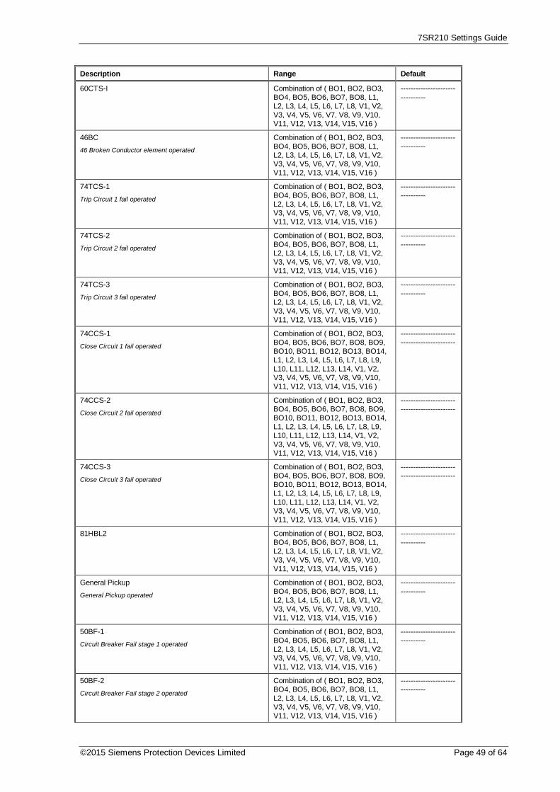
7SR210 Settings Guide
©2015 Siemens Protection Devices Limited Page 49 of 64
Description Range Default
60CTS-I Combination of ( BO1, BO2, BO3,BO4, BO5, BO6, BO7, BO8, L1,L2, L3, L4, L5, L6, L7, L8, V1, V2,V3, V4, V5, V6, V7, V8, V9, V10,V11, V12, V13, V14, V15, V16 )
--------------------------------
46BC
46 Broken Conductor element operated
Combination of ( BO1, BO2, BO3,BO4, BO5, BO6, BO7, BO8, L1,L2, L3, L4, L5, L6, L7, L8, V1, V2,V3, V4, V5, V6, V7, V8, V9, V10,V11, V12, V13, V14, V15, V16 )
--------------------------------
74TCS-1
Trip Circuit 1 fail operated
Combination of ( BO1, BO2, BO3,BO4, BO5, BO6, BO7, BO8, L1,L2, L3, L4, L5, L6, L7, L8, V1, V2,V3, V4, V5, V6, V7, V8, V9, V10,V11, V12, V13, V14, V15, V16 )
--------------------------------
74TCS-2
Trip Circuit 2 fail operated
Combination of ( BO1, BO2, BO3,BO4, BO5, BO6, BO7, BO8, L1,L2, L3, L4, L5, L6, L7, L8, V1, V2,V3, V4, V5, V6, V7, V8, V9, V10,V11, V12, V13, V14, V15, V16 )
--------------------------------
74TCS-3
Trip Circuit 3 fail operated
Combination of ( BO1, BO2, BO3,BO4, BO5, BO6, BO7, BO8, L1,L2, L3, L4, L5, L6, L7, L8, V1, V2,V3, V4, V5, V6, V7, V8, V9, V10,V11, V12, V13, V14, V15, V16 )
--------------------------------
74CCS-1
Close Circuit 1 fail operated
Combination of ( BO1, BO2, BO3,BO4, BO5, BO6, BO7, BO8, BO9,BO10, BO11, BO12, BO13, BO14,L1, L2, L3, L4, L5, L6, L7, L8, L9,L10, L11, L12, L13, L14, V1, V2,V3, V4, V5, V6, V7, V8, V9, V10,V11, V12, V13, V14, V15, V16 )
--------------------------------------------
74CCS-2
Close Circuit 2 fail operated
Combination of ( BO1, BO2, BO3,BO4, BO5, BO6, BO7, BO8, BO9,BO10, BO11, BO12, BO13, BO14,L1, L2, L3, L4, L5, L6, L7, L8, L9,L10, L11, L12, L13, L14, V1, V2,V3, V4, V5, V6, V7, V8, V9, V10,V11, V12, V13, V14, V15, V16 )
--------------------------------------------
74CCS-3
Close Circuit 3 fail operated
Combination of ( BO1, BO2, BO3,BO4, BO5, BO6, BO7, BO8, BO9,BO10, BO11, BO12, BO13, BO14,L1, L2, L3, L4, L5, L6, L7, L8, L9,L10, L11, L12, L13, L14, V1, V2,V3, V4, V5, V6, V7, V8, V9, V10,V11, V12, V13, V14, V15, V16 )
--------------------------------------------
81HBL2 Combination of ( BO1, BO2, BO3,BO4, BO5, BO6, BO7, BO8, L1,L2, L3, L4, L5, L6, L7, L8, V1, V2,V3, V4, V5, V6, V7, V8, V9, V10,V11, V12, V13, V14, V15, V16 )
--------------------------------
General Pickup
General Pickup operated
Combination of ( BO1, BO2, BO3,BO4, BO5, BO6, BO7, BO8, L1,L2, L3, L4, L5, L6, L7, L8, V1, V2,V3, V4, V5, V6, V7, V8, V9, V10,V11, V12, V13, V14, V15, V16 )
--------------------------------
50BF-1
Circuit Breaker Fail stage 1 operated
Combination of ( BO1, BO2, BO3,BO4, BO5, BO6, BO7, BO8, L1,L2, L3, L4, L5, L6, L7, L8, V1, V2,V3, V4, V5, V6, V7, V8, V9, V10,V11, V12, V13, V14, V15, V16 )
--------------------------------
50BF-2
Circuit Breaker Fail stage 2 operated
Combination of ( BO1, BO2, BO3,BO4, BO5, BO6, BO7, BO8, L1,L2, L3, L4, L5, L6, L7, L8, V1, V2,V3, V4, V5, V6, V7, V8, V9, V10,V11, V12, V13, V14, V15, V16 )
--------------------------------

7SR210 Settings Guide
Page 50 of 64 © 2013 Siemens Protection Devices Limited
Description Range Default
50BF PhA
Circuit Breaker Fail Phase A
Combination of ( BO1, BO2, BO3,BO4, BO5, BO6, BO7, BO8, BO9,BO10, BO11, BO12, BO13, BO14,L1, L2, L3, L4, L5, L6, L7, L8, L9,L10, L11, L12, L13, L14, V1, V2,V3, V4, V5, V6, V7, V8, V9, V10,V11, V12, V13, V14, V15, V16 )
--------------------------------------------
50BF PhB
Circuit Breaker Fail Phase B
Combination of ( BO1, BO2, BO3,BO4, BO5, BO6, BO7, BO8, BO9,BO10, BO11, BO12, BO13, BO14,L1, L2, L3, L4, L5, L6, L7, L8, L9,L10, L11, L12, L13, L14, V1, V2,V3, V4, V5, V6, V7, V8, V9, V10,V11, V12, V13, V14, V15, V16 )
--------------------------------------------
50BF PhC
Circuit Breaker Fail Phase C
Combination of ( BO1, BO2, BO3,BO4, BO5, BO6, BO7, BO8, BO9,BO10, BO11, BO12, BO13, BO14,L1, L2, L3, L4, L5, L6, L7, L8, L9,L10, L11, L12, L13, L14, V1, V2,V3, V4, V5, V6, V7, V8, V9, V10,V11, V12, V13, V14, V15, V16 )
--------------------------------------------
50BF EF
Circuit Breaker Fail Earth Fault
Combination of ( BO1, BO2, BO3,BO4, BO5, BO6, BO7, BO8, BO9,BO10, BO11, BO12, BO13, BO14,L1, L2, L3, L4, L5, L6, L7, L8, L9,L10, L11, L12, L13, L14, V1, V2,V3, V4, V5, V6, V7, V8, V9, V10,V11, V12, V13, V14, V15, V16 )
--------------------------------------------
CB Total Trip Count
Total CB trip count exceeded
Combination of ( BO1, BO2, BO3,BO4, BO5, BO6, BO7, BO8, L1,L2, L3, L4, L5, L6, L7, L8, V1, V2,V3, V4, V5, V6, V7, V8, V9, V10,V11, V12, V13, V14, V15, V16 )
--------------------------------
CB Ph A Trip Count
Total CB Ph A trip count exceeded
Combination of ( BO1, BO2, BO3,BO4, BO5, BO6, BO7, BO8, BO9,BO10, BO11, BO12, BO13, BO14,L1, L2, L3, L4, L5, L6, L7, L8, L9,L10, L11, L12, L13, L14, V1, V2,V3, V4, V5, V6, V7, V8, V9, V10,V11, V12, V13, V14, V15, V16 )
--------------------------------------------
CB Ph B Trip Count
Total CB Ph B trip count exceeded
Combination of ( BO1, BO2, BO3,BO4, BO5, BO6, BO7, BO8, BO9,BO10, BO11, BO12, BO13, BO14,L1, L2, L3, L4, L5, L6, L7, L8, L9,L10, L11, L12, L13, L14, V1, V2,V3, V4, V5, V6, V7, V8, V9, V10,V11, V12, V13, V14, V15, V16 )
--------------------------------------------
CB Ph C Trip Count
Total CB Ph C trip count exceeded
Combination of ( BO1, BO2, BO3,BO4, BO5, BO6, BO7, BO8, BO9,BO10, BO11, BO12, BO13, BO14,L1, L2, L3, L4, L5, L6, L7, L8, L9,L10, L11, L12, L13, L14, V1, V2,V3, V4, V5, V6, V7, V8, V9, V10,V11, V12, V13, V14, V15, V16 )
--------------------------------------------
CB E/F Trip Count
Total CB E/F trip count exceeded
Combination of ( BO1, BO2, BO3,BO4, BO5, BO6, BO7, BO8, BO9,BO10, BO11, BO12, BO13, BO14,L1, L2, L3, L4, L5, L6, L7, L8, L9,L10, L11, L12, L13, L14, V1, V2,V3, V4, V5, V6, V7, V8, V9, V10,V11, V12, V13, V14, V15, V16 )
--------------------------------------------
CB Delta Trip Count
Delta CB trip count exceeded
Combination of ( BO1, BO2, BO3,BO4, BO5, BO6, BO7, BO8, L1,L2, L3, L4, L5, L6, L7, L8, V1, V2,V3, V4, V5, V6, V7, V8, V9, V10,V11, V12, V13, V14, V15, V16 )
--------------------------------

7SR210 Settings Guide
©2015 Siemens Protection Devices Limited Page 51 of 64
Description Range Default
CB Count To ARBlock
Count To AR Block CB trip count exceeded
Combination of ( BO1, BO2, BO3,BO4, BO5, BO6, BO7, BO8, L1,L2, L3, L4, L5, L6, L7, L8, V1, V2,V3, V4, V5, V6, V7, V8, V9, V10,V11, V12, V13, V14, V15, V16 )
--------------------------------
CB Freq Ops Count
CB Frequent Operations count exceeded
Combination of ( BO1, BO2, BO3,BO4, BO5, BO6, BO7, BO8, L1,L2, L3, L4, L5, L6, L7, L8, V1, V2,V3, V4, V5, V6, V7, V8, V9, V10,V11, V12, V13, V14, V15, V16 )
--------------------------------
I^2t CB Wear
I^2t CB Wear limit exceeded
Combination of ( BO1, BO2, BO3,BO4, BO5, BO6, BO7, BO8, L1,L2, L3, L4, L5, L6, L7, L8, V1, V2,V3, V4, V5, V6, V7, V8, V9, V10,V11, V12, V13, V14, V15, V16 )
--------------------------------
Trip Time Alarm
Trip Time Alarm operated
Combination of ( BO1, BO2, BO3,BO4, BO5, BO6, BO7, BO8, L1,L2, L3, L4, L5, L6, L7, L8, V1, V2,V3, V4, V5, V6, V7, V8, V9, V10,V11, V12, V13, V14, V15, V16 )
--------------------------------
CB Open
Indicates that the circuit breaker is in the open position.
Combination of ( BO1, BO2, BO3,BO4, BO5, BO6, BO7, BO8, L1,L2, L3, L4, L5, L6, L7, L8, V1, V2,V3, V4, V5, V6, V7, V8, V9, V10,V11, V12, V13, V14, V15, V16 )
--------------------------------
CB Closed
Indicates that the circuit breaker is in the closed position.
Combination of ( BO1, BO2, BO3,BO4, BO5, BO6, BO7, BO8, L1,L2, L3, L4, L5, L6, L7, L8, V1, V2,V3, V4, V5, V6, V7, V8, V9, V10,V11, V12, V13, V14, V15, V16 )
--------------------------------
Close CB Blocked
Indicates that the Close CB control is blocked by itsinterlocking logic.
Combination of ( BO1, BO2, BO3,BO4, BO5, BO6, BO7, BO8, L1,L2, L3, L4, L5, L6, L7, L8, V1, V2,V3, V4, V5, V6, V7, V8, V9, V10,V11, V12, V13, V14, V15, V16 )
--------------------------------
CB Alarm
Indicates the CB is either in an illegal state or is stuck neitheropen or closed.
Combination of ( BO1, BO2, BO3,BO4, BO5, BO6, BO7, BO8, L1,L2, L3, L4, L5, L6, L7, L8, V1, V2,V3, V4, V5, V6, V7, V8, V9, V10,V11, V12, V13, V14, V15, V16 )
--------------------------------
Open CB
Open pulse due to Manual Open being issued.
Combination of ( BO1, BO2, BO3,BO4, BO5, BO6, BO7, BO8, L1,L2, L3, L4, L5, L6, L7, L8, V1, V2,V3, V4, V5, V6, V7, V8, V9, V10,V11, V12, V13, V14, V15, V16 )
--------------------------------
Phase A
A phase A element operated
Combination of ( BO1, BO2, BO3,BO4, BO5, BO6, BO7, BO8, L1,L2, L3, L4, L5, L6, L7, L8, V1, V2,V3, V4, V5, V6, V7, V8, V9, V10,V11, V12, V13, V14, V15, V16 )
L1
Phase B
A phase B element operated
Combination of ( BO1, BO2, BO3,BO4, BO5, BO6, BO7, BO8, L1,L2, L3, L4, L5, L6, L7, L8, V1, V2,V3, V4, V5, V6, V7, V8, V9, V10,V11, V12, V13, V14, V15, V16 )
L2
Phase C
A phase C element operated
Combination of ( BO1, BO2, BO3,BO4, BO5, BO6, BO7, BO8, L1,L2, L3, L4, L5, L6, L7, L8, V1, V2,V3, V4, V5, V6, V7, V8, V9, V10,V11, V12, V13, V14, V15, V16 )
L3

7SR210 Settings Guide
Page 52 of 64 © 2013 Siemens Protection Devices Limited
Description Range Default
Derived E/F
Derive E/F element operated
Combination of ( BO1, BO2, BO3,BO4, BO5, BO6, BO7, BO8, BO9,BO10, BO11, BO12, BO13, BO14,L1, L2, L3, L4, L5, L6, L7, L8, L9,L10, L11, L12, L13, L14, V1, V2,V3, V4, V5, V6, V7, V8, V9, V10,V11, V12, V13, V14, V15, V16 )
--------------------------------------------
Measured E/F
Measured E/F element operated
Combination of ( BO1, BO2, BO3,BO4, BO5, BO6, BO7, BO8, BO9,BO10, BO11, BO12, BO13, BO14,L1, L2, L3, L4, L5, L6, L7, L8, L9,L10, L11, L12, L13, L14, V1, V2,V3, V4, V5, V6, V7, V8, V9, V10,V11, V12, V13, V14, V15, V16 )
--------------------------------------------
Sensitive E/F
Sensitive E/F element operated
Combination of ( BO1, BO2, BO3,BO4, BO5, BO6, BO7, BO8, BO9,BO10, BO11, BO12, BO13, BO14,L1, L2, L3, L4, L5, L6, L7, L8, L9,L10, L11, L12, L13, L14, V1, V2,V3, V4, V5, V6, V7, V8, V9, V10,V11, V12, V13, V14, V15, V16 )
--------------------------------------------
Start Count Alarm Combination of ( BO1, BO2, BO3,BO4, BO5, BO6, BO7, BO8, BO9,BO10, BO11, BO12, BO13, BO14,L1, L2, L3, L4, L5, L6, L7, L8, L9,L10, L11, L12, L13, L14, V1, V2,V3, V4, V5, V6, V7, V8, V9, V10,V11, V12, V13, V14, V15, V16 )
--------------------------------------------
50AFD PhA
Arc Flash Detector Phase A operated
Combination of ( BO1, BO2, BO3,BO4, BO5, BO6, BO7, BO8, BO9,BO10, BO11, BO12, BO13, BO14,L1, L2, L3, L4, L5, L6, L7, L8, L9,L10, L11, L12, L13, L14, V1, V2,V3, V4, V5, V6, V7, V8, V9, V10,V11, V12, V13, V14, V15, V16 )
--------------------------------------------
50AFD PhB
Arc Flash Detector Phase B operated
Combination of ( BO1, BO2, BO3,BO4, BO5, BO6, BO7, BO8, BO9,BO10, BO11, BO12, BO13, BO14,L1, L2, L3, L4, L5, L6, L7, L8, L9,L10, L11, L12, L13, L14, V1, V2,V3, V4, V5, V6, V7, V8, V9, V10,V11, V12, V13, V14, V15, V16 )
--------------------------------------------
50AFD PhC
Arc Flash Detector Phase C operated
Combination of ( BO1, BO2, BO3,BO4, BO5, BO6, BO7, BO8, BO9,BO10, BO11, BO12, BO13, BO14,L1, L2, L3, L4, L5, L6, L7, L8, L9,L10, L11, L12, L13, L14, V1, V2,V3, V4, V5, V6, V7, V8, V9, V10,V11, V12, V13, V14, V15, V16 )
--------------------------------------------
50AFD Combination of ( BO1, BO2, BO3,BO4, BO5, BO6, BO7, BO8, BO9,BO10, BO11, BO12, BO13, BO14,L1, L2, L3, L4, L5, L6, L7, L8, L9,L10, L11, L12, L13, L14, V1, V2,V3, V4, V5, V6, V7, V8, V9, V10,V11, V12, V13, V14, V15, V16 )
--------------------------------------------
AFD Zone 1 Flash Combination of ( BO1, BO2, BO3,BO4, BO5, BO6, BO7, BO8, BO9,BO10, BO11, BO12, BO13, BO14,L1, L2, L3, L4, L5, L6, L7, L8, L9,L10, L11, L12, L13, L14, V1, V2,V3, V4, V5, V6, V7, V8, V9, V10,V11, V12, V13, V14, V15, V16 )
--------------------------------------------

7SR210 Settings Guide
©2015 Siemens Protection Devices Limited Page 53 of 64
Description Range Default
AFD Zone 1 Combination of ( BO1, BO2, BO3,BO4, BO5, BO6, BO7, BO8, BO9,BO10, BO11, BO12, BO13, BO14,L1, L2, L3, L4, L5, L6, L7, L8, L9,L10, L11, L12, L13, L14, V1, V2,V3, V4, V5, V6, V7, V8, V9, V10,V11, V12, V13, V14, V15, V16 )
--------------------------------------------
AFD Zone 2 Flash Combination of ( BO1, BO2, BO3,BO4, BO5, BO6, BO7, BO8, BO9,BO10, BO11, BO12, BO13, BO14,L1, L2, L3, L4, L5, L6, L7, L8, L9,L10, L11, L12, L13, L14, V1, V2,V3, V4, V5, V6, V7, V8, V9, V10,V11, V12, V13, V14, V15, V16 )
--------------------------------------------
AFD Zone 2 Combination of ( BO1, BO2, BO3,BO4, BO5, BO6, BO7, BO8, BO9,BO10, BO11, BO12, BO13, BO14,L1, L2, L3, L4, L5, L6, L7, L8, L9,L10, L11, L12, L13, L14, V1, V2,V3, V4, V5, V6, V7, V8, V9, V10,V11, V12, V13, V14, V15, V16 )
--------------------------------------------
AFD Zone 3 Flash Combination of ( BO1, BO2, BO3,BO4, BO5, BO6, BO7, BO8, BO9,BO10, BO11, BO12, BO13, BO14,L1, L2, L3, L4, L5, L6, L7, L8, L9,L10, L11, L12, L13, L14, V1, V2,V3, V4, V5, V6, V7, V8, V9, V10,V11, V12, V13, V14, V15, V16 )
--------------------------------------------
AFD Zone 3 Combination of ( BO1, BO2, BO3,BO4, BO5, BO6, BO7, BO8, BO9,BO10, BO11, BO12, BO13, BO14,L1, L2, L3, L4, L5, L6, L7, L8, L9,L10, L11, L12, L13, L14, V1, V2,V3, V4, V5, V6, V7, V8, V9, V10,V11, V12, V13, V14, V15, V16 )
--------------------------------------------
AFD Zone 4 Flash Combination of ( BO1, BO2, BO3,BO4, BO5, BO6, BO7, BO8, BO9,BO10, BO11, BO12, BO13, BO14,L1, L2, L3, L4, L5, L6, L7, L8, L9,L10, L11, L12, L13, L14, V1, V2,V3, V4, V5, V6, V7, V8, V9, V10,V11, V12, V13, V14, V15, V16 )
--------------------------------------------
AFD Zone 4 Combination of ( BO1, BO2, BO3,BO4, BO5, BO6, BO7, BO8, BO9,BO10, BO11, BO12, BO13, BO14,L1, L2, L3, L4, L5, L6, L7, L8, L9,L10, L11, L12, L13, L14, V1, V2,V3, V4, V5, V6, V7, V8, V9, V10,V11, V12, V13, V14, V15, V16 )
--------------------------------------------
AFD Zone 5 Flash Combination of ( BO1, BO2, BO3,BO4, BO5, BO6, BO7, BO8, BO9,BO10, BO11, BO12, BO13, BO14,L1, L2, L3, L4, L5, L6, L7, L8, L9,L10, L11, L12, L13, L14, V1, V2,V3, V4, V5, V6, V7, V8, V9, V10,V11, V12, V13, V14, V15, V16 )
--------------------------------------------
AFD Zone 5 Combination of ( BO1, BO2, BO3,BO4, BO5, BO6, BO7, BO8, BO9,BO10, BO11, BO12, BO13, BO14,L1, L2, L3, L4, L5, L6, L7, L8, L9,L10, L11, L12, L13, L14, V1, V2,V3, V4, V5, V6, V7, V8, V9, V10,V11, V12, V13, V14, V15, V16 )
--------------------------------------------

7SR210 Settings Guide
Page 54 of 64 © 2013 Siemens Protection Devices Limited
Description Range Default
AFD Zone 6 Flash Combination of ( BO1, BO2, BO3,BO4, BO5, BO6, BO7, BO8, BO9,BO10, BO11, BO12, BO13, BO14,L1, L2, L3, L4, L5, L6, L7, L8, L9,L10, L11, L12, L13, L14, V1, V2,V3, V4, V5, V6, V7, V8, V9, V10,V11, V12, V13, V14, V15, V16 )
--------------------------------------------
AFD Zone 6 Combination of ( BO1, BO2, BO3,BO4, BO5, BO6, BO7, BO8, BO9,BO10, BO11, BO12, BO13, BO14,L1, L2, L3, L4, L5, L6, L7, L8, L9,L10, L11, L12, L13, L14, V1, V2,V3, V4, V5, V6, V7, V8, V9, V10,V11, V12, V13, V14, V15, V16 )
--------------------------------------------
User Output 1
User Output 1 operated
Combination of ( BO1, BO2, BO3,BO4, BO5, BO6, BO7, BO8, BO9,BO10, BO11, BO12, BO13, BO14,L1, L2, L3, L4, L5, L6, L7, L8, L9,L10, L11, L12, L13, L14, V1, V2,V3, V4, V5, V6, V7, V8, V9, V10,V11, V12, V13, V14, V15, V16 )
--------------------------------------------
---
User Output 32
User Output 32 operated
Combination of ( BO1, BO2, BO3,BO4, BO5, BO6, BO7, BO8, BO9,BO10, BO11, BO12, BO13, BO14,L1, L2, L3, L4, L5, L6, L7, L8, L9,L10, L11, L12, L13, L14, V1, V2,V3, V4, V5, V6, V7, V8, V9, V10,V11, V12, V13, V14, V15, V16 )
--------------------------------------------
En100 Life
Raised when the En100 is communicating correctly with theProtection CPU
Combination of ( BO1, BO2, BO3,BO4, BO5, BO6, BO7, BO8, BO9,BO10, BO11, BO12, BO13, BO14,L1, L2, L3, L4, L5, L6, L7, L8, L9,L10, L11, L12, L13, L14, V1, V2,V3, V4, V5, V6, V7, V8, V9, V10,V11, V12, V13, V14, V15, V16 )
--------------------------------------------
En100 Error
Raised when the En100 has detected an Error
Combination of ( BO1, BO2, BO3,BO4, BO5, BO6, BO7, BO8, BO9,BO10, BO11, BO12, BO13, BO14,L1, L2, L3, L4, L5, L6, L7, L8, L9,L10, L11, L12, L13, L14, V1, V2,V3, V4, V5, V6, V7, V8, V9, V10,V11, V12, V13, V14, V15, V16 )
--------------------------------------------
IEC61850 Configured
Raised when the En100 and Protection CPU are configured forIEC 61850.
Combination of ( BO1, BO2, BO3,BO4, BO5, BO6, BO7, BO8, BO9,BO10, BO11, BO12, BO13, BO14,L1, L2, L3, L4, L5, L6, L7, L8, L9,L10, L11, L12, L13, L14, V1, V2,V3, V4, V5, V6, V7, V8, V9, V10,V11, V12, V13, V14, V15, V16 )
--------------------------------------------
En100 Ch1 Link Down
Raised when En100 Ch 1 Link Down
Combination of ( BO1, BO2, BO3,BO4, BO5, BO6, BO7, BO8, BO9,BO10, BO11, BO12, BO13, BO14,L1, L2, L3, L4, L5, L6, L7, L8, L9,L10, L11, L12, L13, L14, V1, V2,V3, V4, V5, V6, V7, V8, V9, V10,V11, V12, V13, V14, V15, V16 )
--------------------------------------------
En100 Ch2 Link Down
Raised when En100 Ch 2 Link Down
Combination of ( BO1, BO2, BO3,BO4, BO5, BO6, BO7, BO8, BO9,BO10, BO11, BO12, BO13, BO14,L1, L2, L3, L4, L5, L6, L7, L8, L9,L10, L11, L12, L13, L14, V1, V2,V3, V4, V5, V6, V7, V8, V9, V10,V11, V12, V13, V14, V15, V16 )
--------------------------------------------

7SR210 Settings Guide
©2015 Siemens Protection Devices Limited Page 55 of 64
Description Range Default
Manual Close CB
Close pulse due to Manual close being issued
Combination of ( BO1, BO2, BO3,BO4, BO5, BO6, BO7, BO8, L1,L2, L3, L4, L5, L6, L7, L8, V1, V2,V3, V4, V5, V6, V7, V8, V9, V10,V11, V12, V13, V14, V15, V16 )
--------------------------------
79 AR Close CB
Close pulse due to auto-reclose sequence
Combination of ( BO1, BO2, BO3,BO4, BO5, BO6, BO7, BO8, L1,L2, L3, L4, L5, L6, L7, L8, V1, V2,V3, V4, V5, V6, V7, V8, V9, V10,V11, V12, V13, V14, V15, V16 )
--------------------------------
79 Trip & Reclose
Indicates the Trip & Reclose sequence being performed
Combination of ( BO1, BO2, BO3,BO4, BO5, BO6, BO7, BO8, L1,L2, L3, L4, L5, L6, L7, L8, V1, V2,V3, V4, V5, V6, V7, V8, V9, V10,V11, V12, V13, V14, V15, V16 )
--------------------------------
79 Trip & Lockout
Indicates the Trip & Lockout sequence being performed
Combination of ( BO1, BO2, BO3,BO4, BO5, BO6, BO7, BO8, L1,L2, L3, L4, L5, L6, L7, L8, V1, V2,V3, V4, V5, V6, V7, V8, V9, V10,V11, V12, V13, V14, V15, V16 )
--------------------------------
79 Lockout
Indicates the auto-recloser is in the Lockout state
Combination of ( BO1, BO2, BO3,BO4, BO5, BO6, BO7, BO8, L1,L2, L3, L4, L5, L6, L7, L8, V1, V2,V3, V4, V5, V6, V7, V8, V9, V10,V11, V12, V13, V14, V15, V16 )
--------------------------------
79 Out Of Service
Indicates the auto-recloser is out of service
Combination of ( BO1, BO2, BO3,BO4, BO5, BO6, BO7, BO8, L1,L2, L3, L4, L5, L6, L7, L8, V1, V2,V3, V4, V5, V6, V7, V8, V9, V10,V11, V12, V13, V14, V15, V16 )
--------------------------------
79 In Service
Indicates the auto-recloser is in service
Combination of ( BO1, BO2, BO3,BO4, BO5, BO6, BO7, BO8, L1,L2, L3, L4, L5, L6, L7, L8, V1, V2,V3, V4, V5, V6, V7, V8, V9, V10,V11, V12, V13, V14, V15, V16 )
--------------------------------
79 In Progress
Indicates an auto-reclose sequence is in progress
Combination of ( BO1, BO2, BO3,BO4, BO5, BO6, BO7, BO8, L1,L2, L3, L4, L5, L6, L7, L8, V1, V2,V3, V4, V5, V6, V7, V8, V9, V10,V11, V12, V13, V14, V15, V16 )
--------------------------------
79 Block Extern
Indicates that Extern for the current shot has been selected tobe delayed. (This may be used to block external trippingelements in the same way as the internal protection elementsare blocked to achieve Instantaneous / Delayed operation.)
Combination of ( BO1, BO2, BO3,BO4, BO5, BO6, BO7, BO8, L1,L2, L3, L4, L5, L6, L7, L8, V1, V2,V3, V4, V5, V6, V7, V8, V9, V10,V11, V12, V13, V14, V15, V16 )
--------------------------------
79 CB Fail To Close
Indicates the CB was not closed at the end of the Close Pulse
Combination of ( BO1, BO2, BO3,BO4, BO5, BO6, BO7, BO8, L1,L2, L3, L4, L5, L6, L7, L8, V1, V2,V3, V4, V5, V6, V7, V8, V9, V10,V11, V12, V13, V14, V15, V16 )
--------------------------------
79 Close Onto Fault
Indicates an element starter or trip operated during the ClosePulse
Combination of ( BO1, BO2, BO3,BO4, BO5, BO6, BO7, BO8, L1,L2, L3, L4, L5, L6, L7, L8, V1, V2,V3, V4, V5, V6, V7, V8, V9, V10,V11, V12, V13, V14, V15, V16 )
--------------------------------
79 Successful AR
Indicates that after a reclose and at the end of the Reclaimtime the CB was closed and there were no auto-reclose tripelements operated. (This is issued for 2 secs)
Combination of ( BO1, BO2, BO3,BO4, BO5, BO6, BO7, BO8, L1,L2, L3, L4, L5, L6, L7, L8, V1, V2,V3, V4, V5, V6, V7, V8, V9, V10,V11, V12, V13, V14, V15, V16 )
--------------------------------
Successful Man Close
Indicates that after a manual close and at the end of theReclaim time the CB was closed and there were no auto-reclose trip elements operated. (This is issued for 2 secs)
Combination of ( BO1, BO2, BO3,BO4, BO5, BO6, BO7, BO8, L1,L2, L3, L4, L5, L6, L7, L8, V1, V2,V3, V4, V5, V6, V7, V8, V9, V10,V11, V12, V13, V14, V15, V16 )
--------------------------------

7SR210 Settings Guide
Page 56 of 64 © 2013 Siemens Protection Devices Limited
Description Range Default
Hot Line Working
Indicates that Hot LineWorking functionality has been selected
Combination of ( BO1, BO2, BO3,BO4, BO5, BO6, BO7, BO8, L1,L2, L3, L4, L5, L6, L7, L8, V1, V2,V3, V4, V5, V6, V7, V8, V9, V10,V11, V12, V13, V14, V15, V16 )
--------------------------------
Inst Prot'n Out
Indicates that the protection elements selected to beInstantaneous elements are switched out
Combination of ( BO1, BO2, BO3,BO4, BO5, BO6, BO7, BO8, L1,L2, L3, L4, L5, L6, L7, L8, V1, V2,V3, V4, V5, V6, V7, V8, V9, V10,V11, V12, V13, V14, V15, V16 )
--------------------------------
E/F Out
Indicates that the instantaneous protection elements areswitched out.
Combination of ( BO1, BO2, BO3,BO4, BO5, BO6, BO7, BO8, L1,L2, L3, L4, L5, L6, L7, L8, V1, V2,V3, V4, V5, V6, V7, V8, V9, V10,V11, V12, V13, V14, V15, V16 )
--------------------------------
SEF Out
Indicates that the SEF protection elements are switched out
Combination of ( BO1, BO2, BO3,BO4, BO5, BO6, BO7, BO8, L1,L2, L3, L4, L5, L6, L7, L8, V1, V2,V3, V4, V5, V6, V7, V8, V9, V10,V11, V12, V13, V14, V15, V16 )
--------------------------------
New Wave Stored
The waveform recorder has stored new information Note: thisis a pulsed output
Combination of ( BO1, BO2, BO3,BO4, BO5, BO6, BO7, BO8, L1,L2, L3, L4, L5, L6, L7, L8, V1, V2,V3, V4, V5, V6, V7, V8, V9, V10,V11, V12, V13, V14, V15, V16 )
--------------------------------
New Fault Stored
The fault recorder has stored new information Note: this is apulsed output
Combination of ( BO1, BO2, BO3,BO4, BO5, BO6, BO7, BO8, L1,L2, L3, L4, L5, L6, L7, L8, V1, V2,V3, V4, V5, V6, V7, V8, V9, V10,V11, V12, V13, V14, V15, V16 )
--------------------------------
Out Of Service Mode
Indicates the relay is in Out Of Service Mode
Combination of ( BO1, BO2, BO3,BO4, BO5, BO6, BO7, BO8, L1,L2, L3, L4, L5, L6, L7, L8, V1, V2,V3, V4, V5, V6, V7, V8, V9, V10,V11, V12, V13, V14, V15, V16 )
--------------------------------
Local Mode
Indicates the relay is in Local Mode
Combination of ( BO1, BO2, BO3,BO4, BO5, BO6, BO7, BO8, L1,L2, L3, L4, L5, L6, L7, L8, V1, V2,V3, V4, V5, V6, V7, V8, V9, V10,V11, V12, V13, V14, V15, V16 )
--------------------------------
Remote Mode
Indicates the relay is in Remote Mode
Combination of ( BO1, BO2, BO3,BO4, BO5, BO6, BO7, BO8, L1,L2, L3, L4, L5, L6, L7, L8, V1, V2,V3, V4, V5, V6, V7, V8, V9, V10,V11, V12, V13, V14, V15, V16 )
--------------------------------
BI 1 Operated
DC Binary Input 1 has operated
Combination of ( BO1, BO2, BO3,BO4, BO5, BO6, BO7, BO8, L1,L2, L3, L4, L5, L6, L7, L8, V1, V2,V3, V4, V5, V6, V7, V8, V9, V10,V11, V12, V13, V14, V15, V16 )
--------------------------------
BI 2 Operated
DC Binary Input 2 has operated
Combination of ( BO1, BO2, BO3,BO4, BO5, BO6, BO7, BO8, L1,L2, L3, L4, L5, L6, L7, L8, V1, V2,V3, V4, V5, V6, V7, V8, V9, V10,V11, V12, V13, V14, V15, V16 )
--------------------------------
BI 3 Operated
DC Binary Input 3 has operated
Combination of ( BO1, BO2, BO3,BO4, BO5, BO6, BO7, BO8, L1,L2, L3, L4, L5, L6, L7, L8, V1, V2,V3, V4, V5, V6, V7, V8, V9, V10,V11, V12, V13, V14, V15, V16 )
--------------------------------
BI 4 Operated
DC Binary Input 4 has operated
Combination of ( BO1, BO2, BO3,BO4, BO5, BO6, BO7, BO8, L1,L2, L3, L4, L5, L6, L7, L8, V1, V2,V3, V4, V5, V6, V7, V8, V9, V10,V11, V12, V13, V14, V15, V16 )
--------------------------------

7SR210 Settings Guide
©2015 Siemens Protection Devices Limited Page 57 of 64
Description Range Default
BI 5 Operated
DC Binary Input 5 has operated
Combination of ( BO1, BO2, BO3,BO4, BO5, BO6, BO7, BO8, L1,L2, L3, L4, L5, L6, L7, L8, V1, V2,V3, V4, V5, V6, V7, V8, V9, V10,V11, V12, V13, V14, V15, V16 )
--------------------------------
BI 6 Operated
DC Binary Input 6 has operated
Combination of ( BO1, BO2, BO3,BO4, BO5, BO6, BO7, BO8, L1,L2, L3, L4, L5, L6, L7, L8, V1, V2,V3, V4, V5, V6, V7, V8, V9, V10,V11, V12, V13, V14, V15, V16 )
--------------------------------
BI 7 Operated
DC Binary Input 7 has operated
Combination of ( BO1, BO2, BO3,BO4, BO5, BO6, BO7, BO8, L1,L2, L3, L4, L5, L6, L7, L8, V1, V2,V3, V4, V5, V6, V7, V8, V9, V10,V11, V12, V13, V14, V15, V16 )
--------------------------------
BI 8 Operated
DC Binary Input 8 has operated
Combination of ( BO1, BO2, BO3,BO4, BO5, BO6, BO7, BO8, L1,L2, L3, L4, L5, L6, L7, L8, V1, V2,V3, V4, V5, V6, V7, V8, V9, V10,V11, V12, V13, V14, V15, V16 )
--------------------------------
BI 9 Operated
DC Binary Input 9 has operated
Combination of ( BO1, BO2, BO3,BO4, BO5, BO6, BO7, BO8, L1,L2, L3, L4, L5, L6, L7, L8, V1, V2,V3, V4, V5, V6, V7, V8, V9, V10,V11, V12, V13, V14, V15, V16 )
--------------------------------
E1
Quick Logic equation 1 operated
Combination of ( BO1, BO2, BO3,BO4, BO5, BO6, BO7, BO8, L1,L2, L3, L4, L5, L6, L7, L8, V1, V2,V3, V4, V5, V6, V7, V8, V9, V10,V11, V12, V13, V14, V15, V16 )
--------------------------------
E2
Quick Logic equation 2 operated
Combination of ( BO1, BO2, BO3,BO4, BO5, BO6, BO7, BO8, L1,L2, L3, L4, L5, L6, L7, L8, V1, V2,V3, V4, V5, V6, V7, V8, V9, V10,V11, V12, V13, V14, V15, V16 )
--------------------------------
E3
Quick Logic equation 3 operated
Combination of ( BO1, BO2, BO3,BO4, BO5, BO6, BO7, BO8, L1,L2, L3, L4, L5, L6, L7, L8, V1, V2,V3, V4, V5, V6, V7, V8, V9, V10,V11, V12, V13, V14, V15, V16 )
--------------------------------
E4
Quick Logic equation 4 operated
Combination of ( BO1, BO2, BO3,BO4, BO5, BO6, BO7, BO8, L1,L2, L3, L4, L5, L6, L7, L8, V1, V2,V3, V4, V5, V6, V7, V8, V9, V10,V11, V12, V13, V14, V15, V16 )
--------------------------------
E5
Quick Logic equation 5 operated
Combination of ( BO1, BO2, BO3,BO4, BO5, BO6, BO7, BO8, L1,L2, L3, L4, L5, L6, L7, L8, V1, V2,V3, V4, V5, V6, V7, V8, V9, V10,V11, V12, V13, V14, V15, V16 )
--------------------------------
E6
Quick Logic equation 6 operated
Combination of ( BO1, BO2, BO3,BO4, BO5, BO6, BO7, BO8, L1,L2, L3, L4, L5, L6, L7, L8, V1, V2,V3, V4, V5, V6, V7, V8, V9, V10,V11, V12, V13, V14, V15, V16 )
--------------------------------
E7
Quick Logic equation 7 operated
Combination of ( BO1, BO2, BO3,BO4, BO5, BO6, BO7, BO8, L1,L2, L3, L4, L5, L6, L7, L8, V1, V2,V3, V4, V5, V6, V7, V8, V9, V10,V11, V12, V13, V14, V15, V16 )
--------------------------------
E8
Quick Logic equation 8 operated
Combination of ( BO1, BO2, BO3,BO4, BO5, BO6, BO7, BO8, L1,L2, L3, L4, L5, L6, L7, L8, V1, V2,V3, V4, V5, V6, V7, V8, V9, V10,V11, V12, V13, V14, V15, V16 )
--------------------------------

7SR210 Settings Guide
Page 58 of 64 © 2013 Siemens Protection Devices Limited
Description Range Default
E9
Quick Logic equation 9 operated
Combination of ( BO1, BO2, BO3,BO4, BO5, BO6, BO7, BO8, L1,L2, L3, L4, L5, L6, L7, L8, V1, V2,V3, V4, V5, V6, V7, V8, V9, V10,V11, V12, V13, V14, V15, V16 )
--------------------------------
E10
Quick Logic equation 10 operated
Combination of ( BO1, BO2, BO3,BO4, BO5, BO6, BO7, BO8, L1,L2, L3, L4, L5, L6, L7, L8, V1, V2,V3, V4, V5, V6, V7, V8, V9, V10,V11, V12, V13, V14, V15, V16 )
--------------------------------
E11
Quick Logic equation 11 operated
Combination of ( BO1, BO2, BO3,BO4, BO5, BO6, BO7, BO8, L1,L2, L3, L4, L5, L6, L7, L8, V1, V2,V3, V4, V5, V6, V7, V8, V9, V10,V11, V12, V13, V14, V15, V16 )
--------------------------------
E12
Quick Logic equation 12 operated
Combination of ( BO1, BO2, BO3,BO4, BO5, BO6, BO7, BO8, L1,L2, L3, L4, L5, L6, L7, L8, V1, V2,V3, V4, V5, V6, V7, V8, V9, V10,V11, V12, V13, V14, V15, V16 )
--------------------------------
E13
Quick Logic equation 13 operated
Combination of ( BO1, BO2, BO3,BO4, BO5, BO6, BO7, BO8, L1,L2, L3, L4, L5, L6, L7, L8, V1, V2,V3, V4, V5, V6, V7, V8, V9, V10,V11, V12, V13, V14, V15, V16 )
--------------------------------
E14
Quick Logic equation 14 operated
Combination of ( BO1, BO2, BO3,BO4, BO5, BO6, BO7, BO8, L1,L2, L3, L4, L5, L6, L7, L8, V1, V2,V3, V4, V5, V6, V7, V8, V9, V10,V11, V12, V13, V14, V15, V16 )
--------------------------------
E15
Quick Logic equation 15 operated
Combination of ( BO1, BO2, BO3,BO4, BO5, BO6, BO7, BO8, L1,L2, L3, L4, L5, L6, L7, L8, V1, V2,V3, V4, V5, V6, V7, V8, V9, V10,V11, V12, V13, V14, V15, V16 )
--------------------------------
E16
Quick Logic equation 16 operated
Combination of ( BO1, BO2, BO3,BO4, BO5, BO6, BO7, BO8, L1,L2, L3, L4, L5, L6, L7, L8, V1, V2,V3, V4, V5, V6, V7, V8, V9, V10,V11, V12, V13, V14, V15, V16 )
--------------------------------
Trip Contacts
Assigns Output Contact as trip contact for fault trigger
BO1, BO2, BO3, BO4, BO5, BO6,BO7, BO8, BO9, BO10, BO11,BO12, BO13, BO14
--------------------------------------------
Hand Reset Outputs
Assigns Output Contact as hand reset contact
BO1, BO2, BO3, BO4, BO5, BO6,BO7, BO8, BO9, BO10, BO11,BO12, BO13, BO14
--------------------------------------------
Pickup Outputs
Selects which outputs can operate because a pickup conditionexists
BO1, BO2, BO3, BO4, BO5, BO6,BO7, BO8, BO9, BO10, BO11,BO12, BO13, BO14
--------------
Pulsed Outputs
Selects which outputs are pulsed. The pulse width is set bythe Min Operate Time setting for each output
BO1, BO2, BO3, BO4, BO5, BO6,BO7, BO8, BO9, BO10, BO11,BO12, BO13, BO14
--------------
3.8.2. Binary Output Config
Description Range Default
Trip Contacts
The Binary Outputs selected by this setting are classed as Tripcontacts. (When any of these BOs operate the Trip LED is lit,CB Fail is started, if enabled, & a Fault Record is stored)
Combination of ( BO1, BO2, BO3,BO4, BO5, BO6, BO7, BO8 )
--------
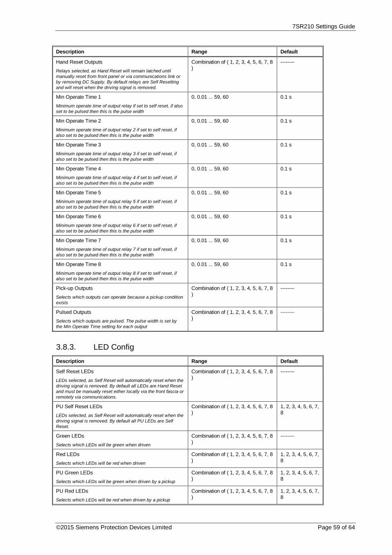
7SR210 Settings Guide
©2015 Siemens Protection Devices Limited Page 59 of 64
Description Range Default
Hand Reset Outputs
Relays selected, as Hand Reset will remain latched untilmanually reset from front panel or via communications link orby removing DC Supply. By default relays are Self Resettingand will reset when the driving signal is removed.
Combination of ( 1, 2, 3, 4, 5, 6, 7, 8)
--------
Min Operate Time 1
Minimum operate time of output relay if set to self reset, if alsoset to be pulsed then this is the pulse width
0, 0.01 ... 59, 60 0.1 s
Min Operate Time 2
Minimum operate time of output relay 2 if set to self reset, ifalso set to be pulsed then this is the pulse width
0, 0.01 ... 59, 60 0.1 s
Min Operate Time 3
Minimum operate time of output relay 3 if set to self reset, ifalso set to be pulsed then this is the pulse width
0, 0.01 ... 59, 60 0.1 s
Min Operate Time 4
Minimum operate time of output relay 4 if set to self reset, ifalso set to be pulsed then this is the pulse width
0, 0.01 ... 59, 60 0.1 s
Min Operate Time 5
Minimum operate time of output relay 5 if set to self reset, ifalso set to be pulsed then this is the pulse width
0, 0.01 ... 59, 60 0.1 s
Min Operate Time 6
Minimum operate time of output relay 6 if set to self reset, ifalso set to be pulsed then this is the pulse width
0, 0.01 ... 59, 60 0.1 s
Min Operate Time 7
Minimum operate time of output relay 7 if set to self reset, ifalso set to be pulsed then this is the pulse width
0, 0.01 ... 59, 60 0.1 s
Min Operate Time 8
Minimum operate time of output relay 8 if set to self reset, ifalso set to be pulsed then this is the pulse width
0, 0.01 ... 59, 60 0.1 s
Pick-up Outputs
Selects which outputs can operate because a pickup conditionexists
Combination of ( 1, 2, 3, 4, 5, 6, 7, 8)
--------
Pulsed Outputs
Selects which outputs are pulsed. The pulse width is set bythe Min Operate Time setting for each output
Combination of ( 1, 2, 3, 4, 5, 6, 7, 8)
--------
3.8.3. LED Config
Description Range Default
Self Reset LEDs
LEDs selected, as Self Reset will automatically reset when thedriving signal is removed. By default all LEDs are Hand Resetand must be manually reset either locally via the front fascia orremotely via communications.
Combination of ( 1, 2, 3, 4, 5, 6, 7, 8)
--------
PU Self Reset LEDs
LEDs selected, as Self Reset will automatically reset when thedriving signal is removed. By default all PU LEDs are SelfReset.
Combination of ( 1, 2, 3, 4, 5, 6, 7, 8)
1, 2, 3, 4, 5, 6, 7,8
Green LEDs
Selects which LEDs will be green when driven
Combination of ( 1, 2, 3, 4, 5, 6, 7, 8)
--------
Red LEDs
Selects which LEDs will be red when driven
Combination of ( 1, 2, 3, 4, 5, 6, 7, 8)
1, 2, 3, 4, 5, 6, 7,8
PU Green LEDs
Selects which LEDs will be green when driven by a pickup
Combination of ( 1, 2, 3, 4, 5, 6, 7, 8)
1, 2, 3, 4, 5, 6, 7,8
PU Red LEDs
Selects which LEDs will be red when driven by a pickup
Combination of ( 1, 2, 3, 4, 5, 6, 7, 8)
1, 2, 3, 4, 5, 6, 7,8

7SR210 Settings Guide
Page 60 of 64 © 2013 Siemens Protection Devices Limited
3.8.4. Pickup Config
Description Range Default
Gn P/F Pickups
When any of the selected pickups operate General Pickup isdriven.
Combination of ( 51-1, 51-2, 50-1,50-2 )
51-1, 51-2, 50-1,50-2
Gn E/F Pickups
As Above
Combination of ( 51N-1, 51N-2,50N-1, 50N-2, 51G-1, 51G-2, 50G-1, 50G-2 )
51N-1, 51N-2,50N-1, 50N-2,51G-1, 51G-2,50G-1, 50G-2
Gn SEF/REF Pickups
As Above
Combination of ( 51SEF-1, 51SEF-2, 50SEF-1, 50SEF-2, 64H )
51SEF-1,51SEF-2,50SEF-1,50SEF-2, 64H
Gn Misc Pickups
As Above
Combination of ( 46IT, 46DT, 37-1,37-2, 37G-1, 37G-2 )
46IT, 46DT, 37-1, 37-2, 37G-1,37G-2

7SR210 Settings Guide
©2015 Siemens Protection Devices Limited Page 61 of 64
3.9. CB Maintenance3.9.1. CB Counters
Description Range Default
Gn CB Total Trip Count
Selects whether the CB Total Trip Count counter is enabled
Disabled, Enabled Disabled
Gn CB Total Trip Count Target
Selects the number of CB trips allowed before CB Total TripCount counter output operates
0, 1 ... 9999, 10000 100
Gn CB Total Trip Count Reset
Resets CB Total Trip Count counter
Gn CB Total Trip Manual Open
Selects whether the CB Total Trip Manual Open is enabled
Disabled, Enabled Disabled
Gn CB Phase Trip Counters
Selects whether the CB Phase Trip Counters is enabled
Disabled, Enabled Disabled
Gn CB Ph A Trip Count Target
Selects the number of CB trips allowed before CB Ph A TripCount counter output operates
0, 1 ... 9999, 10000 100
Gn CB Ph B Trip Count Target
Selects the number of CB trips allowed before CB Ph B TripCount counter output operates
0, 1 ... 9999, 10000 100
Gn CB Ph C Trip Count Target
Selects the number of CB trips allowed before CB Ph C TripCount counter output operates
0, 1 ... 9999, 10000 100
Gn CB E/F Trip Count Target
Selects the number of CB trips allowed before CB E/F TripCount counter output operates
0, 1 ... 9999, 10000 100
Gn CB Delta Trip Count
Selects whether the CB Delta Trip Count counter is enabled
Disabled, Enabled Disabled
Gn CB Delta Trip Count Target
Selects the number of CB trips allowed before CB Delta TripCount counter output operates
0, 1 ... 9999, 10000 100
Gn CB Delta Trip Count Reset
Resets CB Delta Trip Count counter
Gn CB Count To AR Block
Selects whether the CB Count To AR Block counter is enabled
Disabled, Enabled Disabled
Gn CB Count To AR Block Target
Selects the number of CB trips allowed before CB Count ToAR Block counter output operates. While count is above targetthe Autorecloser will only perform 1 x Delayed Shot andLockout
0, 1 ... 9999, 10000 100
Gn CB Count To AR Block Reset
Resets CB Count To AR Block counter
Gn CB Freq Ops Count
Selects whether the CB Frequent Operations Counter isenabled
Disabled, Enabled Disabled
Gn CB Freq Ops Count Target
Selects the number of CB trips allowed before CB FrequentOperations Counter output operates. While count is abovetarget the Autorecloser will only perform 1 x Delayed Shot andLockout
0, 1 ... 9999, 10000 10
Gn CB Freq Ops Count Reset
Resets CB Frequent Operations Counter

7SR210 Settings Guide
Page 62 of 64 © 2013 Siemens Protection Devices Limited
3.9.2. I^2T CB Wear
Description Range Default
Gn I^2t Counter
Selects whether the I^2t CB Wear monitor is enabled
Disabled, Enabled Disabled
Gn Alarm Limit
Sets limit before alarm is issued
10, 11 ... 99000, 100000 10 MA^2 s
Gn Separation Time
Sets the time for CB mechanism to start moving, time beforecontacts start to separate
0, 0.001 ... 0.199, 0.2 0.02 s
Gn Clearance Time
Time for CB to clear fault
0, 0.001 ... 0.199, 0.2 0.04 s
Reset I^2t Count
Reset the CB wear count
3.9.3. START COUNT
Description Range Default
Start Types(s)
Selects which type of start-up
Power On, Expected, Unexpected All
Start Count Target
Selects number of times star-up has occurred before outputoperatest
0, ...10000 100
3.10. Data Storage3.10.1. Demand Data/Log
Description Range Default
Data Log Period
Selects period between stored samples
5, 6, 7, 8, 9, 10, 15, 20, 25, 30, 35,40, 45, 50, 55, 60
5 min
Clear Data Log
Clear the Data Log
Gn Demand Window
The time window over which the Min, Max and Mean valuesare calculated.
1, 2 ... 23, 24 24 hrs
Gn Demand Window Type
Method used to calculate Demand values.
Fixed, Peak, Rolling Fixed
Gn Demand Reset
Reset all Demand values
3.10.2. Waveform Storage
Description Range Default
Gn P/F Trig Storage
Select which elements trigger a waveform record
Combination of ( 51-1, 51-2, 50-1, 50-2 ) 51-1, 51-2, 50-1,50-2
Gn E/F Trig Storage
As Above
Combination of ( 51N-1, 51N-2, 50N-1,50N-2, 51G-1, 51G-2, 50G-1, 50G-2 )
51N-1, 51N-2,50N-1, 50N-2,51G-1, 51G-2,50G-1, 50G-2
Gn SEF/REF Trig Storage
As Above
Combination of ( 51SEF-1, 51SEF-2,50SEF-1, 50SEF-2, 64H )
51SEF-1,51SEF-2,50SEF-1,50SEF-2, 64H

7SR210 Settings Guide
©2015 Siemens Protection Devices Limited Page 63 of 64
Description Range Default
Gn Misc Current Storage
As Above
Combination of ( 46IT, 46DT, 37-1, 37-2,49 Trip, 49 Alarm, 37G-1, 37G-2 )
--------
Gn AFD Trig Storage
As Above
Combination of ( AFD-1, AFD-2, AFD-3,AFD-4, AFD-5, AFD-6)
------
Pre-trigger Storage
Select Percentage of waveform record stored beforethe fault is triggered
10, 20, 30, 40, 50, 60, 70, 80, 90 20 %
Record Duration
Select waveform record duration
10 Rec x 1 Sec, 5 Rec x 2 Sec, 2 Rec x 5Sec, 1 Rec x 10 Sec
10 Rec x 1 Sec
Trigger Waveform
Trigger waveform storage
Clear Waveforms
Clear all stored waveform records
3.10.3. Fault Storage
Description Range Default
Gn Max Fault Rec Time
Maximum time Fault record information will be stored andclassed as same fault
0, 1 ... 59900, 60000 2000 ms
Clear Faults
Clear all stored fault records
3.10.4. Event Storage
Description Range Default
Clear Events
Clear all stored event records
Data Log
Selects whether the Data Logger is enabled
3.10.5. Communications
Description Range Default
Station Address
IEC 60870-5-103 Station Address
0, 1 ... 65533, 65534 0
COM1-RS485 Protocol
Selects protocol to use for COM1-RS485
OFF, IEC60870-5-103, MODBUS-RTU, DNP3
IEC60870-5-103
COM1-RS485 Baud Rate
Sets the communications baud rate for COM1-RS485
75, 110, 150, 300, 600, 1200, 2400,4800, 9600, 19200, 38400
19200
COM1-RS485 Parity
Selects whether parity information is used
NONE, ODD, EVEN EVEN
COM1-RS485 Mode Local, Remote, Local Or Remote Remote
COM2-USB Protocol
Selects protocol to use for COM2-USB
IEC60870-5-103 IEC60870-5-103
COM2-USB Mode Local Local
COM3 Protocol
Selects protocol to use for COM3
OFF, IEC60870-5-103, MODBUS-RTU, DNP3
IEC60870-5-103
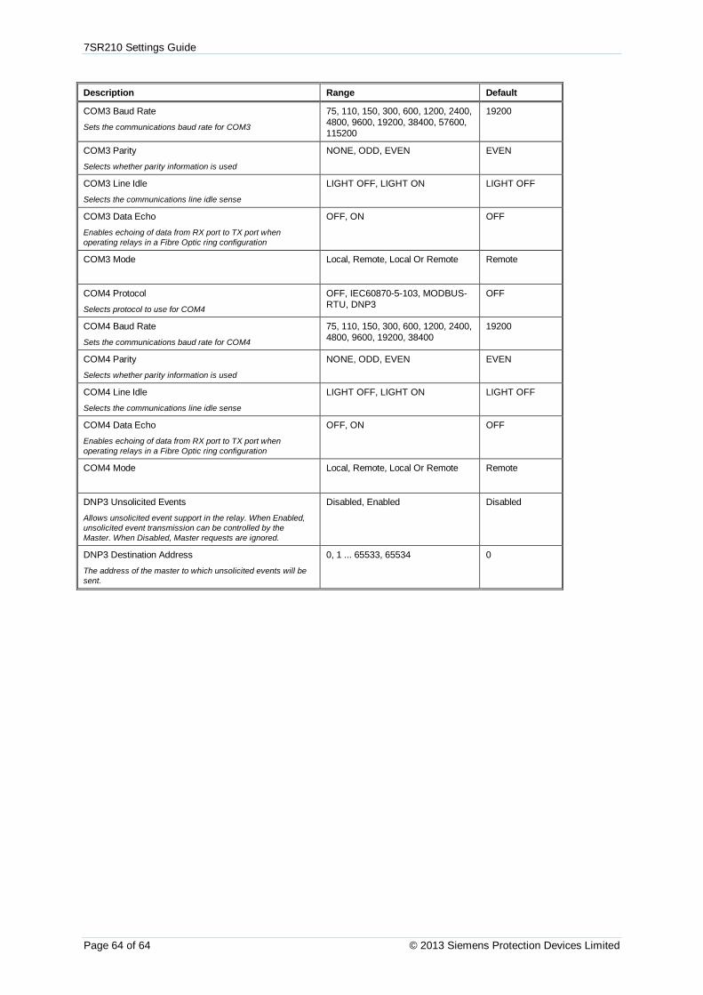
7SR210 Settings Guide
Page 64 of 64 © 2013 Siemens Protection Devices Limited
Description Range Default
COM3 Baud Rate
Sets the communications baud rate for COM3
75, 110, 150, 300, 600, 1200, 2400,4800, 9600, 19200, 38400, 57600,115200
19200
COM3 Parity
Selects whether parity information is used
NONE, ODD, EVEN EVEN
COM3 Line Idle
Selects the communications line idle sense
LIGHT OFF, LIGHT ON LIGHT OFF
COM3 Data Echo
Enables echoing of data from RX port to TX port whenoperating relays in a Fibre Optic ring configuration
OFF, ON OFF
COM3 Mode Local, Remote, Local Or Remote Remote
COM4 Protocol
Selects protocol to use for COM4
OFF, IEC60870-5-103, MODBUS-RTU, DNP3
OFF
COM4 Baud Rate
Sets the communications baud rate for COM4
75, 110, 150, 300, 600, 1200, 2400,4800, 9600, 19200, 38400
19200
COM4 Parity
Selects whether parity information is used
NONE, ODD, EVEN EVEN
COM4 Line Idle
Selects the communications line idle sense
LIGHT OFF, LIGHT ON LIGHT OFF
COM4 Data Echo
Enables echoing of data from RX port to TX port whenoperating relays in a Fibre Optic ring configuration
OFF, ON OFF
COM4 Mode Local, Remote, Local Or Remote Remote
DNP3 Unsolicited Events
Allows unsolicited event support in the relay. When Enabled,unsolicited event transmission can be controlled by theMaster. When Disabled, Master requests are ignored.
Disabled, Enabled Disabled
DNP3 Destination Address
The address of the master to which unsolicited events will besent.
0, 1 ... 65533, 65534 0

The copyright and other intellectual property rights in this document, and in any model or article produced fromit (and including any registered or unregistered design rights) are the property of Siemens Protection DevicesLimited. No part of this document shall be reproduced or modified or stored in another form, in any dataretrieval system, without the permission of Siemens Protection Devices Limited, nor shall any model or articlebe reproduced from this document unless Siemens Protection Devices Limited consent.
While the information and guidance given in this document is believed to be correct, no liability shall beaccepted for any loss or damage caused by any error or omission, whether such error or omission is the resultof negligence or any other cause. Any and all such liability is disclaimed.
© 2013 Siemens Protection Devices Limited
7SR210 Non-Directional Relay
Instrumentation Guide

7SR210 Instrumentation Guide
Page 2 of 11 © 2013 Siemens Protection Devices Limited
Document Release History
This document is issue 2015/06.
2011/05 First issue
2013/01 Typographical revisions and added data. Updated in line with software release.
2014/06 Typographical revisions and added data. Updated in line with software release.
2015/06 Typographical revisions and added data. Updated in line with software release.
Software Revision History2011/05 2435H85008R7a-7a (7SR210) First Release
2013/01 2435H85008R7c-7b (7SR210) Introduced journaling file system.Added 61850 logical nodes for CB Counters, metering, 50BF,46BC,81HBL2 and line check.Added Line Check on non-AR devices.Added 74CCS Close Circuit Supervision.
2014/06 2435H85008R7f-7d (7SR210) Fault data transmitted over 103.Additional communications data control features, meters.
2015/06 2435H85008R8a-7f (7SR210) Added Arc Flash Detector. Over current TM Setting Rangeextended.
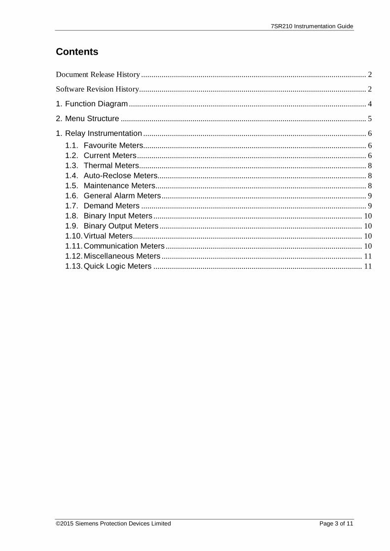
7SR210 Instrumentation Guide
©2015 Siemens Protection Devices Limited Page 3 of 11
Contents
Document Release History .............................................................................................................. 2
Software Revision History ............................................................................................................... 2
1. Function Diagram .................................................................................................................... 4
2. Menu Structure ........................................................................................................................ 5
1. Relay Instrumentation ............................................................................................................. 61.1. Favourite Meters............................................................................................................. 61.2. Current Meters ................................................................................................................ 61.3. Thermal Meters ............................................................................................................... 81.4. Auto-Reclose Meters...................................................................................................... 81.5. Maintenance Meters ....................................................................................................... 81.6. General Alarm Meters .................................................................................................... 91.7. Demand Meters .............................................................................................................. 91.8. Binary Input Meters ...................................................................................................... 101.9. Binary Output Meters ................................................................................................... 101.10.Virtual Meters ................................................................................................................ 101.11.Communication Meters ................................................................................................ 101.12.Miscellaneous Meters .................................................................................................. 111.13.Quick Logic Meters ...................................................................................................... 11

7SR210 Instrumentation Guide
Page 4 of 11 © 2013 Siemens Protection Devices Limited
1.Function Diagram

7SR210 Instrumentation Guide
©2015 Siemens Protection Devices Limited Page 5 of 11
2.Menu Structure

7SR210 Instrumentation Guide
Page 6 of 11 © 2013 Siemens Protection Devices Limited
1. Relay Instrumentation
1.1. Favourite Meters
Instrument Description
--------------------FAVOURITE METERS > to view
This allows the user to view his previously constructed list of ‘favourite meters’by pressing TEST/RESET button and the READ DOWN button to scrollthough the meters added to this sub-group
To construct a sub-group of favourite meters, first go to the desired meter thenpress ENTER this will cause a message to appear on the LCD ‘Add ToFavourites YES pressing ENTER again will add this to the FAVOURITEMETERS Sub-menu. To remove a meter from the FAVOURITE METERS sub-menu go to that meter each in the FAVOURITE METERS sub-menu or at itsPrimary location press ENTER and the message ‘Remove From Favourites’ willappear press ENTER again and this meter will be removed from theFAVOURITE METERS sub-group
1.2. Current Meters
Instrument Description
--------------------CURRENT METERS > to view--------------------
This is the sub-group that includes all the meters that are associated withCurrent TEST/RESET allows access to this sub-group
Primary CurrentIa 0.00AIb 0.00AIc 0.00A
Displays the 3 phase currents Primary RMS values
Secondary CurrentIa 0.00AIb 0.00AIc 0.00A
Displays the 3 phase currents Secondary RMS values
Nom CurrentIa 0.00xIn ----o
Ib 0.00xIn ----o
Ic 0.00xIn ----o
Displays the 3 phase currents Nominal RMS values & phase angles withrespect to PPS current.
Pri Earth CurrentIn 0.000AIg 0.000A
Displays the 3 Earth currents Primary RMS values
Sec Earth CurrentIn 0.000AIg 0.000A
Displays the 3 Earth currents Secondary RMS values
Nom Earth CurrentIn 0.000xIn ----o
Ig 0.000xIn ----o
Displays the 3 Earth currents Nominal RMS values & phase angles with respectto PPS current.
I Seq ComponentsIzps 0.00xIn ----o
Ipps 0.00xIn ----o
Inps 0.00xIn ----o
Displays the Current Sequence components Nominal RMS values & phaseangles with respect to PPS current.
2nd Harmonic CurrentIa 0.00xInIb 0.00xIn
Displays the 3 phase currents 2nd Harmonic components Nominal RMS values.

7SR210 Instrumentation Guide
©2015 Siemens Protection Devices Limited Page 7 of 11
Instrument DescriptionIc 0.00xIn

7SR210 Instrumentation Guide
Page 8 of 11 © 2013 Siemens Protection Devices Limited
1.3. Thermal Meters
Instrument Description
--------------------THERMAL METERS > to view
This is the sub-group that includes all the meters that are associated withThermal TEST/RESET allows access to this sub-group
Thermal StatusPhase A 0.0%Phase B 0.0%Phase C 0.0%
Displays the thermal capacity
1.4. Auto-Reclose Meters
Instrument Description
--------------------AUTORECLOSE METERS > to view--------------------
This is the sub-group that includes all the meters that are associated withAutoreclose TEST/RESET allows access to this sub-group. Only seen onmodels that have the 79 option
Autoreclose StatusOut Of ServiceClose Shot 0
Status of the autoreclose.
1.5. Maintenance Meters
Instrument Description
--------------------MAINTENANCE METERS > to view--------------------
This is the sub-group that includes all the meters that are associated withMaintenance TEST/RESET allows access to this sub-group
CB Total TripsCount 0Target 100
Displays the number of CB trips experienced by the CB
CB Delta TripsCount 0Target 100
Displays the number of CB trips experienced by the CB
CB Count To AR BlockCount 0Target 100
Displays the number of CB trips experienced by the CB. When the target isreached the relay will only do 1 Delayed Trip to Lockout.
CB Freq Ops CountCount 0Target 10
Displays the number of CB trips experienced by the CB over the last rolling 1 hrperiod. When the target is reached the relay will only do 1 Delayed Trip toLockout.
CB WearPhase A 0.00MA^2sPhase B 0.00MA^2sPhase C 0.00MA^2s
Displays the current measure of circuit breaker wear.
CB Trip Time0.0ms
Displays the trip time for the circuit breaker.

7SR210 Instrumentation Guide
©2015 Siemens Protection Devices Limited Page 9 of 11
1.6. General Alarm Meters
Instrument Description
--------------------GENERAL ALARMMETERS > to view--------------------
This is the sub-group that includes all the meters that are associated with theBinary inputs TEST/RESET allows access to this sub-group
General Alarms--------------------ALARM 1 Cleared
Displays the state of General Alarm
…General Alarms--------------------ALARM 20 Cleared
1.7. Demand Meters
Instrument Description
--------------------DEMAND METERS > to view--------------------
This is the sub-group that includes all the meters that are associated with thedemand metering. TEST/RESET allows access to this sub-group
I Phase A DemandMax 0.00AMin 0.00AMean 0.00A
Shows the Max, Min and Mean for Phase A.
I Phase B DemandMax 0.00AMin 0.00AMean 0.00A
Shows the Max, Min and Mean for Phase B.
I Phase C DemandMax 0.00AMin 0.00AMean 0.00A
Shows the Max, Min and Mean for Phase C.
Power P 3P DemandMax 0.00WMin 0.00WMean 0.00W
Shows the Max, Min and Mean for Power P 3P Demand.
Power Q 3P DemandMax 0.00VArMin 0.00VArMean 0.00VAr
Shows the Max, Min and Mean for Power Q 3P Demand.
Power S 3P DemandMax 0.00VAMin 0.00VAMean 0.00VA
Shows the Max, Min and Mean for Power S 3P Demand.

7SR210 Instrumentation Guide
Page 10 of 11 © 2013 Siemens Protection Devices Limited
1.8. Binary Input Meters
Instrument Description
--------------------BINARY INPUT METERS > to view--------------------
This is the sub-group that includes all the meters that are associated with theBinary inputs TEST/RESET allows access to this sub-group
BI 1-8 ---- ----BI 9-9 -
Displays the state of DC binary inputs 1 to 9 (The number of binary inputs mayvary depending on model)
1.9. Binary Output Meters
Instrument Description
--------------------BINARY OUTPUTMETERS > to view--------------------
This is the sub-group that includes all the meters that are associated with theBinary Outputs TEST/RESET allows access to this sub-group
BO 1-8 ---- ---- Displays the state of DC binary Outputs 1 to 8. (The number of binary outputsmay vary depending on model)
1.10. Virtual Meters
Instrument Description
--------------------VIRTUAL METERS > to view--------------------
This is the sub-group that shows the state of the virtual status inputs in the relayTEST/RESET allows access to this sub-group
V 1-8 ---- ----V 9-16 ---- ----
Displays the state of Virtual Outputs 1 to 16 (The number of virtual inputs willvary depending on model)
1.11. Communication Meters
Instrument Description
--------------------COMMUNICATIONMETERS > to view--------------------
This is the sub-group that includes all the meters that are associated withCommunications ports TEST/RESET allows access to this sub-group
COM1COM2COM3COM4
Displays which com ports are currently active
COM1 TRAFFICTx1 0Rx1 0Rx1 Errors 0
Displays traffic on Com1

7SR210 Instrumentation Guide
©2015 Siemens Protection Devices Limited Page 11 of 11
Instrument DescriptionCOM2 TRAFFICTx2 0Rx2 0Rx2 Errors 0
Displays traffic on Com2
COM3 TRAFFICTx3 0Rx3 0Rx3 Errors 0
Displays traffic on Com3
COM4 TRAFFICTx4 0Rx4 0Rx4 Errors 0
Displays traffic on Com4
1.12. Miscellaneous Meters
Instrument Description
--------------------MISCELLANEOUSMETERS > to view--------------------
This is the sub-group that includes indication such as the relays time and date,the amount of fault and waveform records stored in the relay TEST/RESET allows access to this sub-group
Date 01/01/2000Time 22:41:44Waveform Recs 0Fault Recs 0
This meter displays the Date, Time, the number of Waveform Records andFault Records stored in the relay.
Event Recs 0Data Log Recs 0Settings Group 1
This meter displays the number of Event Records, Data Log Records and theActive Settings Group number stored in the relay.
1.13. Quick Logic Meters
Instrument Description
--------------------QUICK LOGIC METERS > to view--------------------
This is the sub-group that includes all the meters that are associated withQuickLogic. TEST/RESET allows access to this sub-group
E 1-8 ---- ----E 9-16 ---- ----
Shows the state of all the equations
E1 EquationEQN =0TMR 0-0 =0CNT 0-1 =0
Shows the state of an individual equation. EQN shows the equation state. TMRshows the timer progress and state for the equation. CNT shows the countprogress and state for the equation.
…E16 EquationEQN =0TMR 0-0 =0CNT 0-1 =0
Shows the state of an individual equation. EQN shows the equation state. TMRshows the timer progress and state for the equation. CNT shows the countprogress and state for the equation.

The copyright and other intellectual property rights in this document, and in any model or article produced fromit (and including any registered or unregistered design rights) are the property of Siemens Protection DevicesLimited. No part of this document shall be reproduced or modified or stored in another form, in any dataretrieval system, without the permission of Siemens Protection Devices Limited, nor shall any model or articlebe reproduced from this document unless Siemens Protection Devices Limited consent.
While the information and guidance given in this document is believed to be correct, no liability shall beaccepted for any loss or damage caused by any error or omission, whether such error or omission is the resultof negligence or any other cause. Any and all such liability is disclaimed.
© 2013 Siemens Protection Devices Limited
7SR220 Directional Relay
Settings Guide
7SR220 Settings Guide
Page 2 of 106 © 2013 Siemens Protection Devices Limited
Document Release History
This document is issue 2015/06
2011/05 First issue
2013/01 Typographical revisions and added data. Updated in line with software release.
2014/06 Typographical revisions and added data. Updated in line with software release.
2015/06 Typographical revisions and added data. Updated in line with software release.
Software Revision History2011/05 2435H85009R7a-7a (7SR220) First Release
2013/01 2435H85009R7c-7b (7SR220) Introduced journaling file system.Added 61850 logical nodes for CB Counters, metering, 50BF,46BC, 81HBL2 and line check.Added Line Check on non-AR devices.Added 74CCS Close Circuit Supervision.
2014/06 2435H85009R7f-7d (7SR220) Added Fault Locator feature and Check Sync feature.Fault data transmitted over 103.Additional communications data, control features, meters.
2015/06 2435H85009R8a-7f (7SR220) Added Power Factor Meters, Load Blinding feature, Arc FlashDetector. Over current TM setting range extended.

7SR220 Settings Guide
©2015 Siemens Protection Devices Limited Page 3 of 106
Contents
Document Release History .............................................................................................................. 2
Software Revision History ............................................................................................................... 2
1. Function Diagram .................................................................................................................... 6
2. Menu Structure ........................................................................................................................ 7
3. Relay Settings .......................................................................................................................... 83.1. System Config ................................................................................................................. 83.2. CT/VT Config .................................................................................................................. 93.3. Function Config ............................................................................................................ 103.4. Current Prot’n................................................................................................................ 12
3.4.1. Phase Overcurrent ............................................................................................ 123.4.1.1. 51-1 ......................................................................................................... 123.4.1.2. 51-2 ......................................................................................................... 133.4.1.3. 51-3 ......................................................................................................... 143.4.1.4. 51-4 ......................................................................................................... 153.4.1.5. 50-1 ......................................................................................................... 153.4.1.6. 50-2 ......................................................................................................... 163.4.1.7. 50-3 ......................................................................................................... 163.4.1.8. 50-4 ......................................................................................................... 17
3.4.2. Voltage Controlled O/C .................................................................................... 173.4.3. Cold Load........................................................................................................... 183.4.4. Derived E/F ........................................................................................................ 19
3.4.4.1. 51N-1 ...................................................................................................... 193.4.4.2. 51N-2 ...................................................................................................... 203.4.4.3. 51N-3 ...................................................................................................... 203.4.4.4. 51N-4 ...................................................................................................... 213.4.4.5. 50N-1 ...................................................................................................... 223.4.4.6. 50N-2 ...................................................................................................... 223.4.4.7. 50N-3 ...................................................................................................... 223.4.4.8. 50N-4 ...................................................................................................... 23
3.4.5. Measured E/F .................................................................................................... 233.4.5.1. 51G-1 ...................................................................................................... 233.4.5.2. 51G-2 ...................................................................................................... 243.4.5.3. 51G-3 ...................................................................................................... 253.4.5.4. 51G-4 ...................................................................................................... 253.4.5.5. 50G-1 ...................................................................................................... 263.4.5.6. 50G-2 ...................................................................................................... 263.4.5.7. 50G-3 ...................................................................................................... 263.4.5.8. 50G-4 ...................................................................................................... 27
3.4.6. Sensitive E/F ..................................................................................................... 273.4.6.1. 51SEF-1 .................................................................................................. 273.4.6.2. 51SEF-2 .................................................................................................. 283.4.6.3. 51SEF-3 .................................................................................................. 283.4.6.4. 51SEF-4 .................................................................................................. 29

7SR220 Settings Guide
Page 4 of 106 © 2013 Siemens Protection Devices Limited
3.4.6.5. 50SEF-1 .................................................................................................. 303.4.6.6. 50SEF-2 .................................................................................................. 303.4.6.7. 50SEF-3 .................................................................................................. 303.4.6.8. 50SEF-4 .................................................................................................. 30
3.4.7. Restricted E/F .................................................................................................... 313.4.8. NPS Overcurrent ............................................................................................... 31
3.4.8.1. 46IT .......................................................................................................... 313.4.8.2. 46DT ........................................................................................................ 31
3.4.9. Under Current .................................................................................................... 323.4.9.1. 37-1 .......................................................................................................... 323.4.9.2. 37-2 .......................................................................................................... 323.4.9.3. 37G-1 ....................................................................................................... 323.4.9.4. 37G-2 ....................................................................................................... 323.4.9.5. 37SEF-1 .................................................................................................. 333.4.9.6. 37SEF-2 .................................................................................................. 33
3.4.10. Thermal ......................................................................................................... 333.4.11. ARC Flash Detector ..................................................................................... 33
3.5. Voltage Protection......................................................................................................... 333.5.1. Phase U/O Voltage ............................................................................................ 333.5.2. 27/59-1 ................................................................................................................ 343.5.3. 27/59-2 ................................................................................................................ 343.5.4. 27/59-3 ................................................................................................................ 353.5.5. 27/59-4 ................................................................................................................ 35
3.6. Vx U/O Voltage .............................................................................................................. 363.7. NPS Overvoltage .......................................................................................................... 36
3.7.1. 47-1 ..................................................................................................................... 363.7.2. 47-2 ..................................................................................................................... 36
3.8. Neutral Overvoltage ...................................................................................................... 373.8.1. 59NIT .................................................................................................................. 373.8.2. 59NDT ................................................................................................................. 37
3.9. U/O Frequency .............................................................................................................. 373.9.1. 81-1 ..................................................................................................................... 383.9.2. 81-2 ..................................................................................................................... 383.9.3. 81-3 ..................................................................................................................... 383.9.4. 81-4 ..................................................................................................................... 393.9.5. 81-5 ..................................................................................................................... 393.9.6. 81-6 ..................................................................................................................... 40
3.10.Supervision .................................................................................................................... 403.10.1. CB Fail .......................................................................................................... 403.10.2. VT Supervision ............................................................................................. 403.10.3. CT Supervision............................................................................................. 413.10.4. Broken Conductor ........................................................................................ 413.10.5. Trip CCT Supervision .................................................................................. 423.10.6. Close CCT Supervision ............................................................................... 423.10.7. Inrush Detector ............................................................................................. 423.10.8. Load Blinder ................................................................................................. 43

7SR220 Settings Guide
©2015 Siemens Protection Devices Limited Page 5 of 106
3.10.8.1. 21LB-3P ............................................................................................. 433.10.8.2. 21LB-1P ............................................................................................. 43
3.11.Control & Logic ............................................................................................................. 433.11.1. Autoreclose Prot’n ....................................................................................... 433.11.2. Autoreclose Config ...................................................................................... 44
3.11.2.1. P/F Shots ........................................................................................... 453.11.2.2. E/F Shots ........................................................................................... 453.11.2.3. SEF Shots.......................................................................................... 463.11.2.4. Extern Shots ...................................................................................... 47
3.11.3. Synchronising Check .................................................................................. 473.11.4. Manual CB Control ...................................................................................... 483.11.5. Circuit Breaker ............................................................................................. 493.11.6. QUICK LOGIC ............................................................................................. 49
3.12. Input Config ................................................................................................................... 583.12.1. Input Matrix .................................................................................................. 583.12.2. Function Key Matrix .................................................................................... 713.12.3. Binary Input Config ..................................................................................... 733.12.4. Function Key Config.................................................................................... 743.12.5. General Alarms ............................................................................................ 75
3.13.Output Config ................................................................................................................ 763.13.1. Output Matrix ............................................................................................... 763.13.2. Binary Output Config .................................................................................. 993.13.3. LED Config ..................................................................................................1003.13.4. Pickup Config..............................................................................................101
3.14.Maintenance ................................................................................................................1013.14.1. CB Counters ...............................................................................................1023.14.2. I^2T CB Wear .............................................................................................1023.14.3. START COUNT ..........................................................................................103
3.15.Data Storage ................................................................................................................1033.15.1. Demand Data/Log ......................................................................................1033.15.2. Waveform Storage .....................................................................................1033.15.3. Fault Storage ..............................................................................................1043.15.4. Event Storage .............................................................................................1043.15.5. Energy Storage ...........................................................................................1043.15.6. Fault Locator ...............................................................................................1053.15.7. Communications .........................................................................................105

7SR220 Settings Guide
Page 6 of 106 © 2013 Siemens Protection Devices Limited
1.Function Diagram

7SR220 Settings Guide
©2015 Siemens Protection Devices Limited Page 7 of 106
2.Menu Structure
7SR220 Settings Guide
Page 8 of 106 © 2013 Siemens Protection Devices Limited
3.Relay Settings3.1. System ConfigDescription Range Default
Active Group
Selects which settings group is currently activated
System Frequency
Selects the Power System Frequency from 50 or 60 Hz
50, 60 50Hz
View/Edit Group
Selects which settings group is currently being displayed
Setting Dependencies
When enabled only active settings are displayed and all othershidden
Disabled, Enabled Enabled
Favourite Meters Timer
Selects the time delay after which, if no key presses havebeen detected, the relay will begin to poll through any screenswhich have been selected as favourite instruments
Off, 1, 2, 5, 10, 15, 30, 60 60 min
Backlight timer
Controls when the LCD backlight turns off
Off, 1, 2, 5, 10, 15, 30, 60 5 min
Date
Sets the date, this setting can only be changed on the fascia orvia Relay->Control->Set Time and Date
Time
Sets the time, this setting can only be changed on the fascia orvia Relay->Control->Set Time and Date
Curr Set Display
Select whether the Pickup values are shown in terms of xNominal, Primary or Secondary values on the Relay Fascia
xNom, Primary, Secondary xNom
E/F Curr Set Display
As Above
xNom, Primary, Secondary xNom
SEF/REF Curr Set Display
As Above
xNom, Primary, Secondary xNom
Export Power/Lag VAr
Selects the signs required for exporting power and laggingVArs
+ve/+ve, +ve/-ve, -ve/+ve, -ve/-ve +ve/+ve
Select Grp Mode
Mode of operation of the group change from status input. Edgetriggered ignores the status input once it has changed to therelevant group, where as with Level triggered the relay willonly stay in the group it has changed to whilst the status inputis being driven, after which it returns to the previous group.
Edge triggered, Level triggered Edge triggered
Clock Sync. From BI
Real time clock may be synchronised using a binary input(See Clock Sync. in Binary Input Menu)
Disabled, Seconds, Minutes Minutes
Operating Mode
Selects the current operating mode of the relay. This can alsobe changed by a binary input mode selection.
Out Of Service, Local, Remote,Local Or Remote
Local Or Remote
Setting Password
Allows a 4 character alpha code to be entered as thepassword. Note that the display shows a password dependantencrypted code on the second line of the display
(Password) NONE
Control Password
As Above
(Password) NONE

7SR220 Settings Guide
©2015 Siemens Protection Devices Limited Page 9 of 106
Description Range Default
Trip Alert
When Enabled the occurance of a Trip will cause the relay todisplay the Trip Alert Screen, the only way to leave this screenis by acknowledging the trip through the TEST/RESET buttonon the relay fascia
Disabled, Enabled Enabled
General Alarm Alert Disabled, Enabled Enabled
Relay Identifier
An alphanumeric string shown on the LCD normally used toidentify the relay or the relays purpose
(16 Character String) ARGUS-M7SR22
Circuit Identifier
An alphanumeric string shown on the LCD normally used toidentifier the circuit the relay is attached to or the relayspurpose
(16 Character String)
3.2. CT/VT ConfigDescription Range Default
Phase Nom Voltage
Selects the nominal voltage setting Vn of the voltage input
40, 40.1 ... 159.9, 160 63.5 V
Phase Voltage Trim Magnitude
Allows trimming of voltage magnitude, the setting value shouldbe the voltage required to be added to get back to Phase NomVoltage.
-20, -19.9 ... 19.9, 20 0 V
Phase Voltage Trim Angle
Allows trimming of voltage angle, the setting value is added tothe current voltage angle
-45, -44.9 ... 44.9, 45 0 deg
Phase Voltage Config
Required to allow for different types of physical VT connections.
Van,Vbn,Vcn, Vab,Vbc,3V0,Va,Vb,Vc
Van,Vbn,Vcn
Phase VT Ratio Prim ( 6 Character String) 132000 V
Phase VT Ratio Sec 40, 40.5 ... 159.5, 160 110 V
Vx Nom Voltage
Selects the nominal voltage setting Vn of the voltage input
40, 40.1 ... 159.9, 160 63.5 V
Vx Voltage Trim Magnitude
Allows trimming of voltage magnitude, the setting value shouldbe the voltage required to be added to get back to Vx NomVoltage.
-20, -19.9 ... 19.9, 20 0 V
Vx Voltage Trim Angle
Allows trimming of voltage angle, the setting value is added tothe current voltage angle
-45, -44.9 ... 44.9, 45 0 deg C
Vx VT Ratio Prim ( 6 Character String) 132000 V
Vx VT Ratio Sec 40, 40.5 ... 159.5, 160 110 V
Phase Current Input
Selects whether 1 or 5 Amp terminals are being used for phaseinputs
1, 5 1 A
Phase CT Ratio Prim
Phase CT ratio to scale primary current instruments
( 6 Character String) 1600 A
Phase CT Ratio Sec
Phase CT ratio to scale secondary current instruments
0.2, 0.21 ... 2, 2.1.....7 1

7SR220 Settings Guide
Page 10 of 106 © 2013 Siemens Protection Devices Limited
Description Range Default
Earth Current Input
Selects whether 1 or 5 Amp terminals are being used forMeasured Earth inputs
1, 5 1 A
Earth CT Ratio Prim
Measured Earth CT ratio to scale primary current instruments
( 6 Character String) 2000 A
Earth CT Ratio Sec
Measured Earth CT ratio to scale secondary current instruments
0.2, 0.21 ... 2, 2.1.....7 1
SEF/REF Current Input
Selects whether 1 or 5 Amp terminals are being used forSEF/REF inputs
1, 5 1 A
SEF/REF CT Ratio Prim
SEF/REF CT ratio to scale primary current instruments
( 6 Character String) 2000 A
SEF/REF CT Ratio Sec
SEF/REF CT ratio to scale primary current instruments
0.2, 0.21 ... 2, 2.1.....7 1
3.3. Function ConfigDescription Range Default
Gn Phase Overcurrent
When set to Disabled, no Phase Overcurrent elements will befunctional and all associated settings will be hidden. (TheSetting Dependencies setting being set to Disabled will makeall settings visible but will not allow them to operate).
Enabled, Disabled Disabled
Gn Voltage Cont O/C
When set to Disabled, no Voltage Cont O/C elements will befunctional and all associated settings will be hidden. (TheSetting Dependencies setting being set to Disabled will makeall settings visible but will not allow them to operate).
Enabled, Disabled Disabled
Gn Cold Load
When set to Disabled, no Cold Load elements will befunctional and all associated settings will be hidden. (TheSetting Dependencies setting being set to Disabled will makeall settings visible but will not allow them to operate).
Enabled, Disabled Disabled
Gn Derived E/F
When set to Disabled, no Derived E/F elements will befunctional and all associated settings will be hidden. (TheSetting Dependencies setting being set to Disabled will makeall settings visible but will not allow them to operate).
Enabled, Disabled Disabled
Gn Measured E/F
When set to Disabled, no Measured E/F elements will befunctional and all associated settings will be hidden. (TheSetting Dependencies setting being set to Disabled will makeall settings visible but will not allow them to operate).
Enabled, Disabled Disabled
Gn Sensitive E/F
When set to Disabled, no Sensitive E/F elements will befunctional and all associated settings will be hidden. (TheSetting Dependencies setting being set to Disabled will makeall settings visible but will not allow them to operate).
Enabled, Disabled Disabled
Gn Restricted E/F
When set to Disabled, no Restricted E/F elements will befunctional and all associated settings will be hidden. (TheSetting Dependencies setting being set to Disabled will makeall settings visible but will not allow them to operate).
Enabled, Disabled Disabled
Gn NPS Overcurrent
When set to Disabled, no NPS Overcurrent elements will befunctional and all associated settings will be hidden. (TheSetting Dependencies setting being set to Disabled will makeall settings visible but will not allow them to operate).
Enabled, Disabled Disabled

7SR220 Settings Guide
©2015 Siemens Protection Devices Limited Page 11 of 106
Description Range Default
Gn Under Current
When set to Disabled, no Under Current elements will befunctional and all associated settings will be hidden. (TheSetting Dependencies setting being set to Disabled will makeall settings visible but will not allow them to operate).
Enabled, Disabled Disabled
Gn Thermal
When set to Disabled, no Thermal elements will be functionaland all associated settings will be hidden. (The SettingDependencies setting being set to Disabled will make allsettings visible but will not allow them to operate).
Enabled, Disabled Disabled
Gn Phase U/O Voltage
When set to Disabled, no Phase U/O Voltage elements will befunctional and all associated settings will be hidden. (TheSetting Dependencies setting being set to Disabled will makeall settings visible but will not allow them to operate).
Enabled, Disabled Disabled
Gn Vx U/O Voltage
When set to Disabled, no Vx U/O Voltage elements will befunctional and all associated settings will be hidden. (TheSetting Dependencies setting being set to Disabled will makeall settings visible but will not allow them to operate).
Enabled, Disabled Disabled
Gn NPS Overvoltage
When set to Disabled, no NPS Overvoltage elements will befunctional and all associated settings will be hidden. (TheSetting Dependencies setting being set to Disabled will makeall settings visible but will not allow them to operate).
Enabled, Disabled Disabled
Gn Neutral Overvoltage
When set to Disabled, no Neutral Overvoltage elements will befunctional and all associated settings will be hidden. (TheSetting Dependencies setting being set to Disabled will makeall settings visible but will not allow them to operate).
Enabled, Disabled Disabled
Gn U/O Frequency
When set to Disabled, no U/O Frequency elements will befunctional and all associated settings will be hidden. (TheSetting Dependencies setting being set to Disabled will makeall settings visible but will not allow them to operate).
Enabled, Disabled Disabled
Gn CB Fail
When set to Disabled, no CB Fail elements will be functionaland all associated settings will be hidden. (The SettingDependencies setting being set to Disabled will make allsettings visible but will not allow them to operate).
Enabled, Disabled Disabled
Gn VT Supervision
When set to Disabled, no VT Supervision elements will befunctional and all associated settings will be hidden. (TheSetting Dependencies setting being set to Disabled will makeall settings visible but will not allow them to operate).
Enabled, Disabled Disabled
Gn CT Supervision
When set to Disabled, no CT Supervision elements will befunctional and all associated settings will be hidden. (TheSetting Dependencies setting being set to Disabled will makeall settings visible but will not allow them to operate).
Enabled, Disabled Disabled
Gn Broken Conductor
When set to Disabled, no Broken Conductor elements will befunctional and all associated settings will be hidden. (TheSetting Dependencies setting being set to Disabled will makeall settings visible but will not allow them to operate).
Enabled, Disabled Disabled
Gn Trip Cct Supervision
When set to Disabled, no Trip Cct Supervision elements willbe functional and all associated settings will be hidden. (TheSetting Dependencies setting being set to Disabled will makeall settings visible but will not allow them to operate).
Enabled, Disabled Disabled

7SR220 Settings Guide
Page 12 of 106 © 2013 Siemens Protection Devices Limited
Description Range Default
Gn Close Cct Supervision
When set to Disabled, no Close Cct Supervision elements willbe functional and all associated settings will be hidden. (TheSetting Dependencies setting being set to Disabled will makeall settings visible but will not allow them to operate).
Enabled, Disabled Disabled
Gn Inrush Detector
When set to Disabled, no Inrush Detector elements will befunctional and all associated settings will be hidden. (TheSetting Dependencies setting being set to Disabled will makeall settings visible but will not allow them to operate).
Enabled, Disabled Disabled
Gn Load Blinder
When set to Disabled, no Load Blinder elements will befunctional and all associated settings will be hidden. (TheSetting Dependencies setting being set to Disabled will makeall settings visible but will not allow them to operate).
Enabled, Disabled Disabled
Gn CB Counters
When set to Disabled, no Gn CB Counter elements will befunctional and all associated settings will be hidden. (TheSetting Dependencies setting being set to Disabled will makeall settings visible but will not allow them to operate).
Enabled, Disabled Disabled
Gn I^2t CB Wear
When set to Disabled, no Gn I^2t CB Wear elements will befunctional and all associated settings will be hidden. (TheSetting Dependencies setting being set to Disabled will makeall settings visible but will not allow them to operate).
Enabled, Disabled Disabled
Gn Arc Flash Detector
When set to Disabled, no Arc Flash Detector elements will befunctional and all associated settings will be hidden. (TheSetting Dependencies setting being set to Disabled will makeall settings visible but will not allow them to operate).
Enabled, Disabled Disabled
3.4. Current Prot’n
3.4.1. Phase Overcurrent
Description Range Default
Gn 67 Char Angle
Maximum torque angle for phase overcurrent elements
-95, -94 ... 94, 95 45 deg
Gn 67 Minimum Voltage
Selects the directional elements minimum voltage, belowwhich the element will be inhibited
1, 1.5 ... 19.5, 20 1 V
Gn 67 2-out-of-3 Logic
Selects whether 2 out of 3 voting logic is enabled for phaseovercurrent elements
Enabled, Disabled Disabled
Gn 50 Measurement
Selects whether the RMS value used by the 50 elements isTrue RMS or only calculated at fundamental frequency
RMS, Fundamental RMS
Gn 51 Measurement
Selects whether the RMS value used by the 51 elements isTrue RMS or only calculated at fundamental frequency
RMS, Fundamental RMS
3.4.1.1. 51-1
Description Range Default
Gn 51-1 Element
Selects whether the 51-1 IDMTL Overcurrent element isenabled
Disabled, Enabled Disabled

7SR220 Settings Guide
©2015 Siemens Protection Devices Limited Page 13 of 106
Description Range Default
Gn 51-1 Dir. Control
Selects whether 51-1 element is non-directional, forward orreverse
Non-Dir, Forward, Reverse Non-Dir
Gn 51-1 Setting
Pickup level
0.05, 0.06 ... 2.49, 2.5 1 xIn
Gn 51-1 Char
Selects characteristic curve to be IEC or ANSI IDMTL or DTL
DTL, IEC-NI, IEC-VI, IEC-EI, IEC-LTI, ANSI-MI, ANSI-VI, ANSI-EI
IEC-NI
Gn 51-1 Time Mult (IEC/ANSI)
Time multiplier (applicable to IEC and ANSI curves but notDTL selection)
0.025, 0.03 ... 1.595, 1.6 , 1.7 ...4.9, 5, 6 ... 100
1
Gn 51-1 Delay (DTL)
Delay (applicable only when DTL is selected for characteristic)
0, 0.01 ... 19.99, 20 5 s
Gn 51-1 Min Operate Time
Minimum operate time of element.
0, 0.01 ... 19.99, 20 0 s
Gn 51-1 Follower DTL
Additional definite time added after characteristic time
0, 0.01 ... 19.99, 20 0s
Gn 51-1 Reset
Selects between an ANSI decaying reset characteristic or adefinite time reset
(ANSI) Decaying, 0 ... 59, 60 0 s
Gn 51-1 VTS Action
Selects whether 51-1 element is blocked or made non-directional when VTS operates
Off, Inhibit, Non-Dir Off
Gn 51-1 Inrush Action
Selects if the 51-1 element is blocked from operating when2nd Harmonic Inrush Detector operates
Off, Inhibit Off
Gn 51-1 21LB-3P Action
Selects if operation of the 51-1 element is blocked for definedload conditions
Off, Inhibit Inhibit
Gn 51-1 21LB-1P Action
Selects if operation of the 51-1 element is blocked for definedload conditions
Off, Inhibit Off
3.4.1.2. 51-2
Description Range Default
Gn 51-2 Element
Selects whether the 51-2 IDMTL Overcurrent element isenabled
Disabled, Enabled Disabled
Gn 51-2 Dir. Control
Selects whether 51-2 element is non-directional, forward orreverse
Non-Dir, Forward, Reverse Non-Dir
Gn 51-2 Setting
Pickup level
0.05, 0.06 ... 2.49, 2.5 1 xIn
Gn 51-2 Char
Selects characteristic curve to be IEC or ANSI IDMTL or DTL
DTL, IEC-NI, IEC-VI, IEC-EI, IEC-LTI, ANSI-MI, ANSI-VI, ANSI-EI
IEC-NI
Gn 51-2 Time Mult (IEC/ANSI)
Time multiplier (applicable to IEC and ANSI curves but notDTL selection)
0.025, 0.03 ... 1.595, 1.6 , 1.7 ...4.9, 5, 6 ... 100
1
Gn 51-2 Delay (DTL)
Delay (applicable only when DTL is selected for characteristic)
0, 0.01 ... 19.99, 20 5 s
Gn 51-2 Min Operate Time
Minimum operate time of element.
0, 0.01 ... 19.99, 20 0 s
Gn 51-2 Follower DTL
Additional definite time added after characteristic time
0, 0.01 ... 19.99, 20 0 s

7SR220 Settings Guide
Page 14 of 106 © 2013 Siemens Protection Devices Limited
Description Range Default
Gn 51-2 Reset
Selects between an ANSI decaying reset characteristic or adefinite time reset
(ANSI) Decaying, 0 ... 59, 60 0 s
Gn 51-2 VTS Action
Selects whether 51-2 element is blocked or made non-directional when VTS operates
Off, Inhibit, Non-Dir Off
Gn 51-2 Inrush Action
Selects if the 51-2 element is blocked from operating when2nd Harmonic Inrush Detector operates
Off, Inhibit Off
Gn 51-2 21LB-3P Action
Selects if operation of the 51-2 element is blocked for definedload conditions
Off, Inhibit Inhibit
Gn 51-2 21LB-1P Action
Selects if operation of the 51-2 element is blocked for definedload conditions
Off, Inhibit Off
3.4.1.3. 51-3
Description Range Default
Gn 51-3 Element
Selects whether the 51-3 IDMTL Overcurrent element isenabled
Disabled, Enabled Disabled
Gn 51-3 Dir. Control
Selects whether 51-3 element is non-directional, forward orreverse
Non-Dir, Forward, Reverse Non-Dir
Gn 51-3 Setting
Pickup level
0.05, 0.06 ... 2.49, 2.5 1 xIn
Gn 51-3 Char
Selects characteristic curve to be IEC or ANSI IDMTL or DTL
DTL, IEC-NI, IEC-VI, IEC-EI, IEC-LTI, ANSI-MI, ANSI-VI, ANSI-EI
IEC-NI
Gn 51-3 Time Mult (IEC/ANSI)
Time multiplier (applicable to IEC and ANSI curves but notDTL selection)
0.025, 0.03 ... 1.595, 1.6 , 1.7 ...4.9, 5, 6 ... 100
1
Gn 51-3 Delay (DTL)
Delay (applicable only when DTL is selected for characteristic)
0, 0.01 ... 19.99, 20 5 s
Gn 51-3 Min Operate Time
Minimum operate time of element.
0, 0.01 ... 19.99, 20 0 s
Gn 51-3 Follower DTL
Additional definite time added after characteristic time
0, 0.01 ... 19.99, 20 0 s
Gn 51-3 Reset
Selects between an ANSI decaying reset characteristic or adefinite time reset
(ANSI) Decaying, 0 ... 59, 60 0 s
Gn 51-3 VTS Action
Selects whether 51-3 element is blocked or made non-directional when VTS operates
Off, Inhibit, Non-Dir Off
Gn 51-3 Inrush Action
Selects if the 51-3 element is blocked from operating when2nd Harmonic Inrush Detector operates
Off, Inhibit Off
Gn 51-3 21LB-3P Action
Selects if operation of the 51-3 element is blocked for definedload conditions
Off, Inhibit Inhibit
Gn 51-3 21LB-1P Action
Selects if operation of the 51-3 element is blocked for definedload conditions
Off, Inhibit Off

7SR220 Settings Guide
©2015 Siemens Protection Devices Limited Page 15 of 106
3.4.1.4. 51-4
Description Range Default
Gn 51-4 Element
Selects whether the 51-4 IDMTL Overcurrent element isenabled
Disabled, Enabled Disabled
Gn 51-4 Dir. Control
Selects whether 51-4 element is non-directional, forward orreverse
Non-Dir, Forward, Reverse Non-Dir
Gn 51-4 Setting
Pickup level
0.05, 0.06 ... 2.49, 2.5 1 xIn
Gn 51-4 Char
Selects characteristic curve to be IEC or ANSI IDMTL or DTL
DTL, IEC-NI, IEC-VI, IEC-EI, IEC-LTI, ANSI-MI, ANSI-VI, ANSI-EI
IEC-NI
Gn 51-4 Time Mult (IEC/ANSI)
Time multiplier (applicable to IEC and ANSI curves but notDTL selection)
0.025, 0.03 ... 1.595, 1.6 , 1.7 ...4.9, 5, 6 ... 100
1
Gn 51-4 Delay (DTL)
Delay (applicable only when DTL is selected for characteristic)
0, 0.01 ... 19.99, 20 5 s
Gn 51-4 Min Operate Time
Minimum operate time of element.
0, 0.01 ... 19.99, 20 0 s
Gn 51-4 Follower DTL
Additional definite time added after characteristic time
0, 0.01 ... 19.99, 20 0 s
Gn 51-4 Reset
Selects between an ANSI decaying reset characteristic or adefinite time reset
(ANSI) Decaying, 0 ... 59, 60 0 s
Gn 51-4 VTS Action
Selects whether 51-4 element is blocked or made non-directional when VTS operates
Off, Inhibit, Non-Dir Off
Gn 51-4 Inrush Action
Selects if the 51-4 element is blocked from operating when2nd Harmonic Inrush Detector operates
Off, Inhibit Off
Gn 51-4 21LB-3P Action
Selects if operation of the 51-4 element is blocked for definedload conditions
Off, Inhibit Inhibit
Gn 51-4 21LB-1P Action
Selects if operation of the 51-4 element is blocked for definedload conditions
Off, Inhibit Off
3.4.1.5. 50-1
Description Range Default
Gn 50-1 Element
Selects whether the INST/ DTL Overcurrent element isenabled
Disabled, Enabled Disabled
Gn 50-1 Dir. Control
Selects whether 50-1 element is non-directional, forward orreverse
Non-Dir, Forward, Reverse Non-Dir
Gn 50-1 Setting
Pickup level
0.05, 0.06 ... 49.5, 50 1 xIn
Gn 50-1 Delay
Sets operate delay time
0, 0.01 ... 14300, 14400 0 s
Gn 50-1 VTS Action
Selects whether 50-1 element is blocked or made non-directional when VTS operates
Off, Inhibit, Non-Dir Off

7SR220 Settings Guide
Page 16 of 106 © 2013 Siemens Protection Devices Limited
Description Range Default
Gn 50-1 Inrush Action
Selects if the 50-1 element is blocked from operating when2nd Harmonic Inrush Detector operates
Off, Inhibit Off
Gn 50-1 21LB-3P Action
Selects if operation of the 50-1 element is blocked for definedload conditions
Off, Inhibit Inhibit
Gn 50-1 21LB-1P Action
Selects if operation of the 50-1 element is blocked for definedload conditions
Off, Inhibit Off
3.4.1.6. 50-2
Description Range Default
Gn 50-2 Element
Selects whether the INST/ DTL Overcurrent element isenabled
Disabled, Enabled Disabled
Gn 50-2 Dir. Control
Selects whether 50-2 element is non-directional, forward orreverse
Non-Dir, Forward, Reverse Non-Dir
Gn 50-2 Setting
Pickup level
0.05, 0.06 ... 49.5, 50 1 xIn
Gn 50-2 Delay
Sets operate delay time
0, 0.01 ... 14300, 14400 0 s
Gn 50-2 VTS Action
Selects whether 50-2 element is blocked or made non-directional when VTS operates
Off, Inhibit, Non-Dir Off
Gn 50-2 Inrush Action
Selects if the 50-2 element is blocked from operating when2nd Harmonic Inrush Detector operates
Off, Inhibit Off
Gn 50-2 21LB-3P Action
Selects if operation of the 50-2 element is blocked for definedload conditions
Off, Inhibit Inhibit
Gn 50-2 21LB-1P Action
Selects if operation of the 50-2 element is blocked for definedload conditions
Off, Inhibit Off
3.4.1.7. 50-3
Description Range Default
Gn 50-3 Element
Selects whether the INST/ DTL Overcurrent element isenabled
Disabled, Enabled Disabled
Gn 50-3 Dir. Control
Selects whether 50-3 element is non-directional, forward orreverse
Non-Dir, Forward, Reverse Non-Dir
Gn 50-3 Setting
Pickup level
0.05, 0.06 ... 49.5, 50 1 xIn
Gn 50-3 Delay
Sets operate delay time
0, 0.01 ... 14300, 14400 0 s
Gn 50-3 VTS Action
Selects whether 50-3 element is blocked or made non-directional when VTS operates
Off, Inhibit, Non-Dir Off
Gn 50-3 Inrush Action
Selects if the 50-3 element is blocked from operating when2nd Harmonic Inrush Detector operates
Off, Inhibit Off
7SR220 Settings Guide
©2015 Siemens Protection Devices Limited Page 17 of 106
Description Range Default
Gn 50-3 21LB-3P Action
Selects if operation of the 50-3 element is blocked for definedload conditions
Off, Inhibit Inhibit
Gn 50-3 21LB-1P Action
Selects if operation of the 50-3 element is blocked for definedload conditions
Off, Inhibit Off
3.4.1.8. 50-4
Description Range Default
Gn 50-4 Element
Selects whether the INST/ DTL Overcurrent element isenabled
Disabled, Enabled Disabled
Gn 50-4 Dir. Control
Selects whether 50-4 element is non-directional, forward orreverse
Non-Dir, Forward, Reverse Non-Dir
Gn 50-4 Setting
Pickup level
0.05, 0.06 ... 49.5, 50 1 xIn
Gn 50-4 Delay
Sets operate delay time
0, 0.01 ... 14300, 14400 0 s
Gn 50-4 VTS Action
Selects whether 50-4 element is blocked or made non-directional when VTS operates
Off, Inhibit, Non-Dir Off
Gn 50-4 Inrush Action
Selects if the 50-4 element is blocked from operating when2nd Harmonic Inrush Detector operates
Off, Inhibit Off
Gn 50-4 21LB-3P Action
Selects if operation of the 50-4 element is blocked for definedload conditions
Off, Inhibit Inhibit
Gn 50-4 21LB-1P Action
Selects if operation of the 50-4 element is blocked for definedload conditions
Off, Inhibit Off
3.4.2. Voltage Controlled O/C
Description Range Default
Gn 51V Element (Ph-Ph) Disabled, Enabled Disabled
Gn 51V Setting
The voltage below which 51V operates
5, 5.5 ... 199.5, 200 30 V
Gn 51V VTS Action
Selects whether or not the 51V element is blocked when VTSoperates
Off, Inhibit Off
Gn 51-1 Multiplier
Multiplier applied to the 51-1 element when VCO element hasoperated
0.25, 0.3, 0.35, 0.4, 0.45, 0.5, 0.55,0.6, 0.65, 0.7, 0.75, 0.8, 0.85, 0.9,0.95, 1
0.5
Gn 51-2 Multiplier
Multiplier applied to the 51-2 element when VCO element hasoperated
0.25, 0.3, 0.35, 0.4, 0.45, 0.5, 0.55,0.6, 0.65, 0.7, 0.75, 0.8, 0.85, 0.9,0.95, 1
0.5
Gn 51-3 Multiplier
Multiplier applied to the 51-3 element when VCO element hasoperated
0.25, 0.3, 0.35, 0.4, 0.45, 0.5, 0.55,0.6, 0.65, 0.7, 0.75, 0.8, 0.85, 0.9,0.95, 1
0.5
Gn 51-4 Multiplier
Multiplier applied to the 51-4 element when VCO element hasoperated
0.25, 0.3, 0.35, 0.4, 0.45, 0.5, 0.55,0.6, 0.65, 0.7, 0.75, 0.8, 0.85, 0.9,0.95, 1
0.5

7SR220 Settings Guide
Page 18 of 106 © 2013 Siemens Protection Devices Limited
3.4.3. Cold Load
Description Range Default
Cold Load
Selects whether the Cold Load element is enabled
Disabled, Enabled Disabled
Pick-up Time
Cold Load operate time delay
1, 1.1 ... 14100, 14400 600 s
Drop-off Time
Cold Load reset time delay
1, 1.1 ... 14100, 14400 600 s
Reduced Current
Selects whether reduced current functionality is to be used
Disabled, Enabled Disabled
Reduced Current Level
Selects current level below which Reduced Current Time isused for Cold Load reset delay
0.05, 0.1 ... 2.45, 2.5 0.25 xIn
Reduced Current Time
Cold Load reset time delay used when reduced current active
1, 1.1 ... 14100, 14400 600 s
Gn 51c-1 Setting
51-1 element parameter used when Cold Load operates
0.05, 0.06 ... 2.49, 2.5 1 xIn
Gn 51c-1 Char
As Above
DTL, IEC-NI, IEC-VI, IEC-EI, IEC-LTI, ANSI-MI, ANSI-VI, ANSI-EI
IEC-NI
Gn 51c-1 Time Mult (IEC/ANSI)
As Above
0.025, 0.03 ... 1.595, 1.6 , 1.7 ...4.9, 5, 6 ... 100
1
Gn 51c-1 Delay (DTL)
As Above
0, 0.01 ... 19.99, 20 5 s
Gn 51c-1 Min Operate Time
As Above
0, 0.01 ... 19.99, 20 0 s
Gn 51c-1 Follower DTL
As Above
0, 0.01 ... 19.99, 20 0 s
Gn 51c-1 Reset
As Above
(ANSI) Decaying, 0 ... 59, 60 0 s
Gn 51c-2 Setting
51-2 element parameter used when Cold Load operates
0.05, 0.06 ... 2.49, 2.5 1 xIn
Gn 51c-2 Char
As Above
DTL, IEC-NI, IEC-VI, IEC-EI, IEC-LTI, ANSI-MI, ANSI-VI, ANSI-EI
IEC-NI
Gn 51c-2 Time Mult (IEC/ANSI)
As Above
0.025, 0.03 ... 1.595, 1.6 , 1.7 ...4.9, 5, 6 ... 100
1
Gn 51c-2 Delay (DTL)
As Above
0, 0.01 ... 19.99, 20 5 s
Gn 51c-2 Min Operate Time
As Above
0, 0.01 ... 19.99, 20 0 s
Gn 51c-2 Follower DTL
As Above
0, 0.01 ... 19.99, 20 0 s
Gn 51c-2 Reset
As Above
(ANSI) Decaying, 0 ... 59, 60 0 s
Gn 51c-3 Setting
51-3 element parameter used when Cold Load operates
0.05, 0.06 ... 2.49, 2.5 1 xIn
Gn 51c-3 Char
As Above
DTL, IEC-NI, IEC-VI, IEC-EI, IEC-LTI, ANSI-MI, ANSI-VI, ANSI-EI
IE C-NI
Gn 51c-3 Time Mult (IEC/ANSI)
As Above
0.025, 0.03 ... 1.595, 1.6 , 1.7 ...4.9, 5, 6 ... 100
1

7SR220 Settings Guide
©2015 Siemens Protection Devices Limited Page 19 of 106
Description Range Default
Gn 51c-3 Delay (DTL)
As Above
0, 0.01 ... 19.99, 20 5 s
Gn 51c-3 Min Operate Time
As Above
0, 0.01 ... 19.99, 20 0 s
Gn 51c-3 Follower DTL
As Above
0, 0.01 ... 19.99, 20 0 s
Gn 51c-3 Reset
As Above
(ANSI) Decaying, 0 ... 59, 60 0 s
Gn 51c-4 Setting
51-4 element parameter used when Cold Load operates
0.05, 0.06 ... 2.49, 2.5 1 xIn
Gn 51c-4 Char
As Above
DTL, IEC-NI, IEC-VI, IEC-EI, IEC-LTI, ANSI-MI, ANSI-VI, ANSI-EI
IEC-NI
Gn 51c-4 Time Mult (IEC/ANSI)
As Above
0.025, 0.03 ... 1.595, 1.6 , 1.7 ...4.9, 5, 6 ... 100
1
Gn 51c-4 Delay (DTL)
As Above
0, 0.01 ... 19.99, 20 5 s
Gn 51c-4 Min Operate Time
As Above
0, 0.01 ... 19.99, 20 0 s
Gn 51c-4 Follower DTL
As Above
0, 0.01 ... 19.99, 20 0 s
Gn 51c-4 Reset
As Above
(ANSI) Decaying, 0 ... 59, 60 0 s
3.4.4. Derived E/F
Description Range Default
Gn 67N Polarizing Quantity
Allows the directional element to select which quantities touse.
ZPS, NPS ZPS
Gn 67N Char Angle
Maximum torque angle for derived earth fault elements
-95, -94 ... 94, 95 -15 deg
Gn 67N Minimum Voltage
Selects the directional elements minimum voltage, belowwhich the element will be inhibited
0.33, 0.5, 1, 1.5, 2, 2.5, 3 0.33 V
3.4.4.1. 51N-1
Description Range Default
Gn 51N-1 Element
Selects whether the 51N-1 IDMTL derived Earth Fault elementis enabled
Disabled, Enabled Disabled
Gn 51N-1 Dir. Control
Selects whether 51N-1 element is non-directional, forward orreverse
Non-Dir, Forward, Reverse Non-Dir
Gn 51N-1 Setting
Pickup level
0.05, 0.06 ... 2.49, 2.5 0.5 xIn
Gn 51N-1 Char
Selects characteristic curve to be IEC or ANSI IDMTL or DTL
DTL, IEC-NI, IEC-VI, IEC-EI, IEC-LTI, ANSI-MI, ANSI-VI, ANSI-EI
IEC-NI
Gn 51N-1 Time Mult (IEC/ANSI)
Time multiplier (applicable to IEC and ANSI curves but notDTL selection)
0.025, 0.03 ... 1.595, 1.6 , 1.7 ...4.9, 5, 6 ... 100
1

7SR220 Settings Guide
Page 20 of 106 © 2013 Siemens Protection Devices Limited
Description Range Default
Gn 51N-1 Delay (DTL)
Delay (applicable only when DTL is selected for characteristic)
0, 0.01 ... 19.99, 20 5 s
Gn 51N-1 Min Operate Time
Minimum operate time of element.
0, 0.01 ... 19.99, 20 0 s
Gn 51N-1 Follower DTL
Additional definite time added after characteristic time
0, 0.01 ... 19.99, 20 0 s
Gn 51N-1 Reset
Selects between an ANSI decaying reset characteristic or adefinite time reset
(ANSI) Decaying, 0 ... 59, 60 0 s
Gn 51N-1 VTS Action
Selects whether 51N-1 element is blocked or made non-directional when VTS operates
Off, Inhibit, Non-Dir Off
Gn 51N-1 Inrush Action
Selects if the 51N-1 element is blocked from operating when2nd Harmonic Inrush Detector operates
Off, Inhibit Off
3.4.4.2. 51N-2
Description Range Default
Gn 51N-2 Element
Selects whether the 51N-2 IDMTL derived Earth Fault elementis enabled
Disabled, Enabled Disabled
Gn 51N-2 Dir. Control
Selects whether 51N-2 element is non-directional, forward orreverse
Non-Dir, Forward, Reverse Non-Dir
Gn 51N-2 Setting
Pickup level
0.05, 0.06 ... 2.49, 2.5 0.5xIn
Gn 51N-2 Char
Selects characteristic curve to be IEC or ANSI IDMTL or DTL
DTL, IEC-NI, IEC-VI, IEC-EI, IEC-LTI, ANSI-MI, ANSI-VI, ANSI-EI
IEC-NI
Gn 51N-2 Time Mult (IEC/ANSI)
Time multiplier (applicable to IEC and ANSI curves but notDTL selection)
0.025, 0.03 ... 1.595, 1.6 , 1.7 ...4.9, 5, 6 ... 100
1
Gn 51N-2 Delay (DTL)
Delay (applicable only when DTL is selected for characteristic)
0, 0.01 ... 19.99, 20 5 s
Gn 51N-2 Min Operate Time
Minimum operate time of element.
0, 0.01 ... 19.99, 20 0 s
Gn 51N-2 Follower DTL
Additional definite time added after characteristic time
0, 0.01 ... 19.99, 20 0s
Gn 51N-2 Reset
Selects between an ANSI decaying reset characteristic or adefinite time reset
(ANSI) Decaying, 0 ... 59, 60 0 s
Gn 51N-2 VTS Action
Selects whether 51N-2 element is blocked or made non-directional when VTS operates
Off, Inhibit, Non-Dir Off
Gn 51N-2 Inrush Action
Selects if the 51N-2 element is blocked from operating when2nd Harmonic Inrush Detector operates
Off, Inhibit Off
3.4.4.3. 51N-3
Description Range Default
Gn 51N-3 Element
Selects whether the 51N-3 IDMTL derived Earth Fault elementis enabled
Disabled, Enabled Disabled

7SR220 Settings Guide
©2015 Siemens Protection Devices Limited Page 21 of 106
Description Range Default
Gn 51N-3 Dir. Control
Selects whether 51N-3 element is non-directional, forward orreverse
Non-Dir, Forward, Reverse Non-Dir
Gn 51N-3 Setting
Pickup level
0.05, 0.06 ... 2.49, 2.5 0.5 xIn
Gn 51N-3 Char
Selects characteristic curve to be IEC or ANSI IDMTL or DTL
DTL, IEC-NI, IEC-VI, IEC-EI, IEC-LTI, ANSI-MI, ANSI-VI, ANSI-EI
IEC-NI
Gn 51N-3 Time Mult (IEC/ANSI)
Time multiplier (applicable to IEC and ANSI curves but notDTL selection)
0.025, 0.03 ... 1.595, 1.6 , 1.7 ...4.9, 5, 6 ... 100
1
Gn 51N-3 Delay (DTL)
Delay (applicable only when DTL is selected for characteristic)
0, 0.01 ... 19.99, 20 5 s
Gn 51N-3 Min Operate Time
Minimum operate time of element.
0, 0.01 ... 19.99, 20 0 s
Gn 51N-3 Follower DTL
Additional definite time added after characteristic time
0, 0.01 ... 19.99, 20 0 s
Gn 51N-3 Reset
Selects between an ANSI decaying reset characteristic or adefinite time reset
(ANSI) Decaying, 0 ... 59, 60 0 s
Gn 51N-3 VTS Action
Selects whether 51N-3 element is blocked or made non-directional when VTS operates
Off, Inhibit, Non-Dir Off
Gn 51N-3 Inrush Action
Selects if the 51N-3 element is blocked from operating when2nd Harmonic Inrush Detector operates
Off, Inhibit Off
3.4.4.4. 51N-4
Description Range Default
Gn 51N-4 Element
Selects whether the 51N-4 IDMTL derived Earth Fault elementis enabled
Disabled, Enabled Disabled
Gn 51N-4 Dir. Control
Selects whether 51N-4 element is non-directional, forward orreverse
Non-Dir, Forward, Reverse Non-Dir
Gn 51N-4 Setting
Pickup level
0.05, 0.06 ... 2.49, 2.5 0.5 xIn
Gn 51N-4 Char
Selects characteristic curve to be IEC or ANSI IDMTL or DTL
DTL, IEC-NI, IEC-VI, IEC-EI, IEC-LTI, ANSI-MI, ANSI-VI, ANSI-EI
IEC-NI
Gn 51N-4 Time Mult (IEC/ANSI)
Time multiplier (applicable to IEC and ANSI curves but notDTL selection)
0.025, 0.03 ... 1.595, 1.6 , 1.7 ...4.9, 5, 6 ... 100
1
Gn 51N-4 Delay (DTL)
Delay (applicable only when DTL is selected for characteristic)
0, 0.01 ... 19.99, 20 5 s
Gn 51N-4 Min Operate Time
Minimum operate time of element.
0, 0.01 ... 19.99, 20 0 s
Gn 51N-4 Follower DTL
Additional definite time added after characteristic time
0, 0.01 ... 19.99, 20 0 s
Gn 51N-4 Reset
Selects between an ANSI decaying reset characteristic or adefinite time reset
(ANSI) Decaying, 0 ... 59, 60 0 s
Gn 51N-4 VTS Action
Selects whether 51N-4 element is blocked or made non-directional when VTS operates
Off, Inhibit, Non-Dir Off
7SR220 Settings Guide
Page 22 of 106 © 2013 Siemens Protection Devices Limited
Description Range Default
Gn 51N-4 Inrush Action
Selects if the 51N-4 element is blocked from operating when2nd Harmonic Inrush Detector operates
Off, Inhibit Off
3.4.4.5. 50N-1
Description Range Default
Gn 50N-1 Element
Selects whether the DTL derived Earth fault element isenabled
Disabled, Enabled Disabled
Gn 50N-1 Dir. Control
Selects whether 50N-1 element is non-directional, forward orreverse
Non-Dir, Forward, Reverse Non-Dir
Gn 50N-1 Setting
Pickup level
0.05, 0.06 ... 49.5, 50 0.5 xIn
Gn 50N-1 Delay
Sets operate delay time
0, 0.01 ... 14300, 14400 0s
Gn 50N-1 VTS Action
Selects whether 50N-1 element is blocked or made non-directional when VTS operates
Off, Inhibit, Non-Dir Off
Gn 50N-1 Inrush Action
Selects if the 50N-1 element is blocked from operating when2nd Harmonic Inrush Detector operates
Off, Inhibit Off
3.4.4.6. 50N-2
Description Range Default
Gn 50N-2 Element
Selects whether the DTL derived Earth fault element isenabled
Disabled, Enabled Disabled
Gn 50N-2 Dir. Control
Selects whether 50N-2 element is non-directional, forward orreverse
Non-Dir, Forward, Reverse Non-Dir
Gn 50N-2 Setting
Pickup level
0.05, 0.06 ... 49.5, 50 0.5 xIn
Gn 50N-2 Delay
Sets operate delay time
0, 0.01 ... 14300, 14400 0 s
Gn 50N-2 VTS Action
Selects whether 50N-2 element is blocked or made non-directional when VTS operates
Off, Inhibit, Non-Dir Off
Gn 50N-2 Inrush Action
Selects if the 50N-2 element is blocked from operating when2nd Harmonic Inrush Detector operates
Off, Inhibit Off
3.4.4.7. 50N-3
Description Range Default
Gn 50N-3 Element
Selects whether the DTL derived Earth fault element isenabled
Disabled, Enabled Disabled
Gn 50N-3 Dir. Control
Selects whether 50N-3 element is non-directional, forward orreverse
Non-Dir, Forward, Reverse Non-Dir
Gn 50N-3 Setting
Pickup level
0.05, 0.06 ... 49.5, 50 0.5 xIn
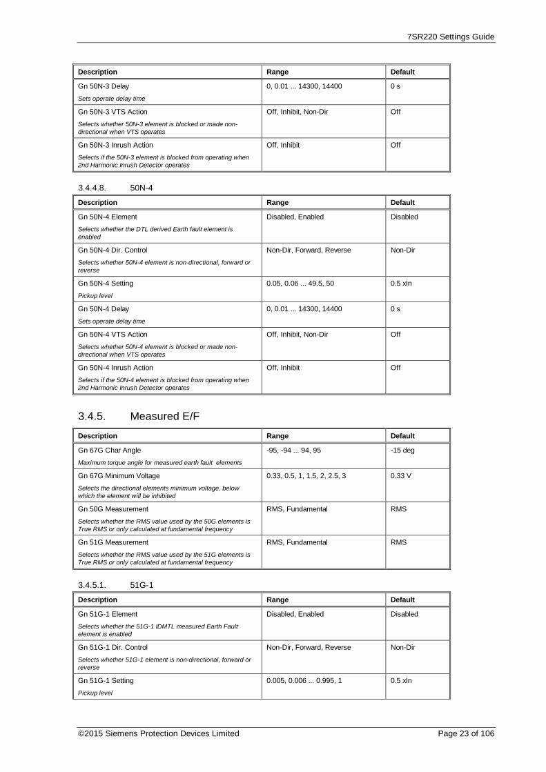
7SR220 Settings Guide
©2015 Siemens Protection Devices Limited Page 23 of 106
Description Range Default
Gn 50N-3 Delay
Sets operate delay time
0, 0.01 ... 14300, 14400 0 s
Gn 50N-3 VTS Action
Selects whether 50N-3 element is blocked or made non-directional when VTS operates
Off, Inhibit, Non-Dir Off
Gn 50N-3 Inrush Action
Selects if the 50N-3 element is blocked from operating when2nd Harmonic Inrush Detector operates
Off, Inhibit Off
3.4.4.8. 50N-4
Description Range Default
Gn 50N-4 Element
Selects whether the DTL derived Earth fault element isenabled
Disabled, Enabled Disabled
Gn 50N-4 Dir. Control
Selects whether 50N-4 element is non-directional, forward orreverse
Non-Dir, Forward, Reverse Non-Dir
Gn 50N-4 Setting
Pickup level
0.05, 0.06 ... 49.5, 50 0.5 xIn
Gn 50N-4 Delay
Sets operate delay time
0, 0.01 ... 14300, 14400 0 s
Gn 50N-4 VTS Action
Selects whether 50N-4 element is blocked or made non-directional when VTS operates
Off, Inhibit, Non-Dir Off
Gn 50N-4 Inrush Action
Selects if the 50N-4 element is blocked from operating when2nd Harmonic Inrush Detector operates
Off, Inhibit Off
3.4.5. Measured E/F
Description Range Default
Gn 67G Char Angle
Maximum torque angle for measured earth fault elements
-95, -94 ... 94, 95 -15 deg
Gn 67G Minimum Voltage
Selects the directional elements minimum voltage, belowwhich the element will be inhibited
0.33, 0.5, 1, 1.5, 2, 2.5, 3 0.33 V
Gn 50G Measurement
Selects whether the RMS value used by the 50G elements isTrue RMS or only calculated at fundamental frequency
RMS, Fundamental RMS
Gn 51G Measurement
Selects whether the RMS value used by the 51G elements isTrue RMS or only calculated at fundamental frequency
RMS, Fundamental RMS
3.4.5.1. 51G-1
Description Range Default
Gn 51G-1 Element
Selects whether the 51G-1 IDMTL measured Earth Faultelement is enabled
Disabled, Enabled Disabled
Gn 51G-1 Dir. Control
Selects whether 51G-1 element is non-directional, forward orreverse
Non-Dir, Forward, Reverse Non-Dir
Gn 51G-1 Setting
Pickup level
0.005, 0.006 ... 0.995, 1 0.5 xIn

7SR220 Settings Guide
Page 24 of 106 © 2013 Siemens Protection Devices Limited
Description Range Default
Gn 51G-1 Char
Selects characteristic curve to be IEC or ANSI IDMTL or DTL
DTL, IEC-NI, IEC-VI, IEC-EI, IEC-LTI, ANSI-MI, ANSI-VI, ANSI-EI
IEC-NI
Gn 51G-1 Time Mult (IEC/ANSI)
Time multiplier (applicable to IEC and ANSI curves but notDTL selection)
0.025, 0.03 ... 1.595, 1.6 , 1.7 ...4.9, 5, 6 ... 100
1
Gn 51G-1 Delay (DTL)
Delay (applicable only when DTL is selected for characteristic)
0, 0.01 ... 19.99, 20 5 s
Gn 51G-1 Min Operate Time
Minimum operate time of element.
0, 0.01 ... 19.99, 20 0 s
Gn 51G-1 Follower DTL
Additional definite time added after characteristic time
0, 0.01 ... 19.99, 20 0 s
Gn 51G-1 Reset
Selects between an ANSI decaying reset characteristic or DTLreset
(ANSI) Decaying, 0 ... 59, 60 0 s
Gn 51G-1 VTS Action
Selects whether 51G-1 element is blocked or made non-directional when VTS operates
Off, Inhibit, Non-Dir Off
Gn 51G-1 Inrush Action
Selects if the 51G-1 element is blocked from operating when2nd Harmonic Inrush Detector operates
Off, Inhibit Off
3.4.5.2. 51G-2
Description Range Default
Gn 51G-2 Element
Selects whether the 51G-2 IDMTL measured Earth Faultelement is enabled
Disabled, Enabled Disabled
Gn 51G-2 Dir. Control
Selects whether 51G-2 element is non-directional, forward orreverse
Non-Dir, Forward, Reverse Non-Dir
Gn 51G-2 Setting
Pickup level
0.005, 0.006 ... 0.995, 1 0.5 xIn
Gn 51G-2 Char
Selects characteristic curve to be IEC or ANSI IDMTL or DTL
DTL, IEC-NI, IEC-VI, IEC-EI, IEC-LTI, ANSI-MI, ANSI-VI, ANSI-EI
IEC-NI
Gn 51G-2 Time Mult (IEC/ANSI)
Time multiplier (applicable to IEC and ANSI curves but notDTL selection)
0.025, 0.03 ... 1.595, 1.6 , 1.7 ...4.9, 5, 6 ... 100
1
Gn 51G-2 Delay (DTL)
Delay (applicable only when DTL is selected for characteristic)
0, 0.01 ... 19.99, 20 5 s
Gn 51G-2 Min Operate Time
Minimum operate time of element.
0, 0.01 ... 19.99, 20 0 s
Gn 51G-2 Follower DTL
Additional definite time added after characteristic time
0, 0.01 ... 19.99, 20 0 s
Gn 51G-2 Reset
Selects between an ANSI decaying reset characteristic or DTLreset
(ANSI) Decaying, 0 ... 59, 60 0 s
Gn 51G-2 VTS Action
Selects whether 51G-2 element is blocked or made non-directional when VTS operates
Off, Inhibit, Non-Dir Off
Gn 51G-2 Inrush Action
Selects if the 51G-2 element is blocked from operating when2nd Harmonic Inrush Detector operates
Off, Inhibit Off

7SR220 Settings Guide
©2015 Siemens Protection Devices Limited Page 25 of 106
3.4.5.3. 51G-3
Description Range Default
Gn 51G-3 Element
Selects whether the 51G-3 IDMTL measured Earth Faultelement is enabled
Disabled, Enabled Disabled
Gn 51G-3 Dir. Control
Selects whether 51G-3 element is non-directional, forward orreverse
Non-Dir, Forward, Reverse Non-Dir
Gn 51G-3 Setting
Pickup level
0.005, 0.006 ... 0.995, 1 0.5 xIn
Gn 51G-3 Char
Selects characteristic curve to be IEC or ANSI IDMTL or DTL
DTL, IEC-NI, IEC-VI, IEC-EI, IEC-LTI, ANSI-MI, ANSI-VI, ANSI-EI
IEC-NI
Gn 51G-3 Time Mult (IEC/ANSI)
Time multiplier (applicable to IEC and ANSI curves but notDTL selection)
0.025, 0.03 ... 1.595, 1.6 , 1.7 ...4.9, 5, 6 ... 100
1
Gn 51G-3 Delay (DTL)
Delay (applicable only when DTL is selected for characteristic)
0, 0.01 ... 19.99, 20 5 s
Gn 51G-3 Min Operate Time
Minimum operate time of element.
0, 0.01 ... 19.99, 20 0 s
Gn 51G-3 Follower DTL
Additional definite time added after characteristic time
0, 0.01 ... 19.99, 20 0 s
Gn 51G-3 Reset
Selects between an ANSI decaying reset characteristic or DTLreset
(ANSI) Decaying, 0 ... 59, 60 0 s
Gn 51G-3 VTS Action
Selects whether 51G-3 element is blocked or made non-directional when VTS operates
Off, Inhibit, Non-Dir Off
Gn 51G-3 Inrush Action
Selects if the 51G-3 element is blocked from operating when2nd Harmonic Inrush Detector operates
Off, Inhibit Off
3.4.5.4. 51G-4
Description Range Default
Gn 51G-4 Element
Selects whether the 51G-4 IDMTL measured Earth Faultelement is enabled
Disabled, Enabled Disabled
Gn 51G-4 Dir. Control
Selects whether 51G-4 element is non-directional, forward orreverse
Non-Dir, Forward, Reverse Non-Dir
Gn 51G-4 Setting
Pickup level
0.005, 0.006 ... 0.995, 1 0.5 xIn
Gn 51G-4 Char
Selects characteristic curve to be IEC or ANSI IDMTL or DTL
DTL, IEC-NI, IEC-VI, IEC-EI, IEC-LTI, ANSI-MI, ANSI-VI, ANSI-EI
IEC-NI
Gn 51G-4 Time Mult (IEC/ANSI)
Time multiplier (applicable to IEC and ANSI curves but notDTL selection)
0.025, 0.03 ... 1.595, 1.6 , 1.7 ...4.9, 5, 6 ... 100
1
Gn 51G-4 Delay (DTL)
Delay (applicable only when DTL is selected for characteristic)
0, 0.01 ... 19.99, 20 5 s
Gn 51G-4 Min Operate Time
Minimum operate time of element.
0, 0.01 ... 19.99, 20 0 s
Gn 51G-4 Follower DTL
Additional definite time added after characteristic time
0, 0.01 ... 19.99, 20 0 s

7SR220 Settings Guide
Page 26 of 106 © 2013 Siemens Protection Devices Limited
Description Range Default
Gn 51G-4 Reset
Selects between an ANSI decaying reset characteristic or DTLreset
(ANSI) Decaying, 0 ... 59, 60 0 s
Gn 51G-4 VTS Action
Selects whether 51G-4 element is blocked or made non-directional when VTS operates
Off, Inhibit, Non-Dir Off
Gn 51G-4 Inrush Action
Selects if the 51G-4 element is blocked from operating when2nd Harmonic Inrush Detector operates
Off, Inhibit Off
3.4.5.5. 50G-1
Description Range Default
Gn 50G-1 Element
Selects whether the DTL measured Earth fault element isenabled
Disabled, Enabled Disabled
Gn 50G-1 Dir. Control
Selects whether 50G-1 element is non-directional, forward orreverse
Non-Dir, Forward, Reverse Non-Dir
Gn 50G-1 Setting
Pickup level
0.005, 0.006 ... 24.95, 25 0.5 xIn
Gn 50G-1 Delay
Sets operate delay time
0, 0.01 ... 14300, 14400 0 s
Gn 50G-1 VTS Action
Selects whether 50G-1 element is blocked or made non-directional when VTS operates
Off, Inhibit, Non-Dir Off
Gn 50G-1 Inrush Action
Selects if the 50G-1 element is blocked from operating when2nd Harmonic Inrush Detector operates
Off, Inhibit Off
3.4.5.6. 50G-2
Description Range Default
Gn 50G-2 Element
Selects whether the DTL measured Earth fault element isenabled
Disabled, Enabled Disabled
Gn 50G-2 Dir. Control
Selects whether 50G-2 element is non-directional, forward orreverse
Non-Dir, Forward, Reverse Non-Dir
Gn 50G-2 Setting
Pickup level
0.005, 0.006 ... 24.95, 25 0.5 xIn
Gn 50G-2 Delay
Sets operate delay time
0, 0.01 ... 14300, 14400 0 s
Gn 50G-2 VTS Action
Selects whether 50G-2 element is blocked or made non-directional when VTS operates
Off, Inhibit, Non-Dir Off
Gn 50G-2 Inrush Action
Selects if the 50G-2 element is blocked from operating when2nd Harmonic Inrush Detector operates
Off, Inhibit Off
3.4.5.7. 50G-3
Description Range Default
Gn 50G-3 Element
Selects whether the DTL measured Earth fault element isenabled
Disabled, Enabled Disabled

7SR220 Settings Guide
©2015 Siemens Protection Devices Limited Page 27 of 106
Description Range Default
Gn 50G-3 Dir. Control
Selects whether 50G-3 element is non-directional, forward orreverse
Non-Dir, Forward, Reverse Non-Dir
Gn 50G-3 Setting
Pickup level
0.005, 0.006 ... 24.95, 25 0.5 xIn
Gn 50G-3 Delay
Sets operate delay time
0, 0.01 ... 14300, 14400 0 s
Gn 50G-3 VTS Action
Selects whether 50G-3 element is blocked or made non-directional when VTS operates
Off, Inhibit, Non-Dir Off
Gn 50G-3 Inrush Action
Selects if the 50G-3 element is blocked from operating when2nd Harmonic Inrush Detector operates
Off, Inhibit Off
3.4.5.8. 50G-4
Description Range Default
Gn 50G-4 Element
Selects whether the DTL measured Earth fault element isenabled
Disabled, Enabled Disabled
Gn 50G-4 Dir. Control
Selects whether 50G-4 element is non-directional, forward orreverse
Non-Dir, Forward, Reverse Non-Dir
Gn 50G-4 Setting
Pickup level
0.005, 0.006 ... 24.95, 25 0.5 xIn
Gn 50G-4 Delay
Sets operate delay time
0, 0.01 ... 14300, 14400 0 s
Gn 50G-4 VTS Action
Selects whether 50G-4 element is blocked or made non-directional when VTS operates
Off, Inhibit, Non-Dir Off
Gn 50G-4 Inrush Action
Selects if the 50G-4 element is blocked from operating when2nd Harmonic Inrush Detector operates
Off, Inhibit Off
3.4.6. Sensitive E/F
Description Range Default
Gn 67SEF Char Angle
Maximum torque angle for sensitive earth fault elements
-95, -94 ... 94, 95 -15 deg
Gn 67SEF Minimum Voltage
Selects the directional elements minimum voltage, belowwhich the element will be inhibited
0.33, 0.5, 1, 1.5, 2, 2.5, 3 0.33 V
3.4.6.1. 51SEF-1
Description Range Default
Gn 51SEF-1 Element
Selects whether the 51SEF-1 IDMTL Sensitive Earth Faultelement is enabled
Disabled, Enabled Disabled
Gn 51SEF-1 Dir. Control
Selects whether 51SEF-1 element is non-directional, forwardor reverse
Non-Dir, Forward, Reverse Non-Dir
Gn 51SEF-1 Setting
Pickup level
0.005, 0.006 ... 0.995, 1 0.2 xIn

7SR220 Settings Guide
Page 28 of 106 © 2013 Siemens Protection Devices Limited
Description Range Default
Gn 51SEF-1 Char
Selects characteristic curve to be IEC or ANSI IDMTL or DTL
DTL, IEC-NI, IEC-VI, IEC-EI, IEC-LTI, ANSI-MI, ANSI-VI, ANSI-EI
IEC-NI
Gn 51SEF-1 Time Mult (IEC/ANSI)
Time multiplier (applicable to IEC and ANSI curves but notDTL selection)
0.025, 0.03 ... 1.595, 1.6 , 1.7 ...4.9, 5, 6 ... 100
1
Gn 51SEF-1 Delay (DTL)
Delay (applicable only when DTL is selected for characteristic)
0, 0.01 ... 19.99, 20 5 s
Gn 51SEF-1 Min Operate Time
Minimum operate time of element.
0, 0.01 ... 19.99, 20 0 s
Gn 51SEF-1 Follower DTL
Additional definite time added after characteristic time
0, 0.01 ... 19.99, 20 0 s
Gn 51SEF-1 Reset
Selects between an ANSI decaying reset characteristic or DTLreset
(ANSI) Decaying, 0 ... 59, 60 0 s
Gn 51SEF-1 VTS Action
Selects whether 51SEF-1 element is blocked or made non-directional when VTS operates
Off, Inhibit, Non-Dir Off
3.4.6.2. 51SEF-2
Description Range Default
Gn 51SEF-2 Element
Selects whether the 51SEF-2 IDMTL derived Earth Faultelement is enabled
Disabled, Enabled Disabled
Gn 51SEF-2 Dir. Control
Selects whether 51SEF-2 element is non-directional, forwardor reverse
Non-Dir, Forward, Reverse Non-Dir
Gn 51SEF-2 Setting
Pickup level
0.005, 0.006 ... 0.995, 1 0.2 xIn
Gn 51SEF-2 Char
Selects characteristic curve to be IEC or ANSI IDMTL or DTL
DTL, IEC-NI, IEC-VI, IEC-EI, IEC-LTI, ANSI-MI, ANSI-VI, ANSI-EI
IEC-NI
Gn 51SEF-2 Time Mult (IEC/ANSI)
Time multiplier (applicable to IEC and ANSI curves but notDTL selection)
0.025, 0.03 ... 1.595, 1.6 , 1.7 ...4.9, 5, 6 ... 100
1
Gn 51SEF-2 Delay (DTL)
Delay (applicable only when DTL is selected for characteristic)
0, 0.01 ... 19.99, 20 5 s
Gn 51SEF-2 Min Operate Time
Minimum operate time of element.
0, 0.01 ... 19.99, 20 0 s
Gn 51SEF-2 Follower DTL
Additional definite time added after characteristic time
0, 0.01 ... 19.99, 20 0 s
Gn 51SEF-2 Reset
Selects between an ANSI decaying reset characteristic or DTLreset
(ANSI) Decaying, 0 ... 59, 60 0 s
Gn 51SEF-2 VTS Action
Selects whether 51SEF-2 element is blocked or made non-directional when VTS operates
Off, Inhibit, Non-Dir Off
3.4.6.3. 51SEF-3
Description Range Default
Gn 51SEF-3 Element
Selects whether the 51SEF-3 IDMTL derived Earth Faultelement is enabled
Disabled, Enabled Disabled

7SR220 Settings Guide
©2015 Siemens Protection Devices Limited Page 29 of 106
Description Range Default
Gn 51SEF-3 Dir. Control
Selects whether 51SEF-3 element is non-directional, forwardor reverse
Non-Dir, Forward, Reverse Non-Dir
Gn 51SEF-3 Setting
Pickup level
0.005, 0.006 ... 0.995, 1 0.2 xIn
Gn 51SEF-3 Char
Selects characteristic curve to be IEC or ANSI IDMTL or DTL
DTL, IEC-NI, IEC-VI, IEC-EI, IEC-LTI, ANSI-MI, ANSI-VI, ANSI-EI
IEC-NI
Gn 51SEF-3 Time Mult (IEC/ANSI)
Time multiplier (applicable to IEC and ANSI curves but notDTL selection)
0.025, 0.03 ... 1.595, 1.6 , 1.7 ...4.9, 5, 6 ... 100
1
Gn 51SEF-3 Delay (DTL)
Delay (applicable only when DTL is selected for characteristic)
0, 0.01 ... 19.99, 20 5 s
Gn 51SEF-3 Min Operate Time
Minimum operate time of element.
0, 0.01 ... 19.99, 20 0 s
Gn 51SEF-3 Follower DTL
Additional definite time added after characteristic time
0, 0.01 ... 19.99, 20 0 s
Gn 51SEF-3 Reset
Selects between an ANSI decaying reset characteristic or adefinite time reset
(ANSI) Decaying, 0 ... 59, 60 0 s
Gn 51SEF-3 VTS Action
Selects whether 51SEF-3 element is blocked or made non-directional when VTS operates
Off, Inhibit, Non-Dir Off
3.4.6.4. 51SEF-4
Description Range Default
Gn 51SEF-4 Element
Selects whether the 51SEF-4 IDMTL derived Earth Faultelement is enabled
Disabled, Enabled Disabled
Gn 51SEF-4 Dir. Control
Selects whether 51SEF-4 element is non-directional, forwardor reverse
Non-Dir, Forward, Reverse Non-Dir
Gn 51SEF-4 Setting
Pickup level
0.005, 0.006 ... 0.995, 1 0.2 xIn
Gn 51SEF-4 Char
Selects characteristic curve to be IEC or ANSI IDMTL or DTL
DTL, IEC-NI, IEC-VI, IEC-EI, IEC-LTI, ANSI-MI, ANSI-VI, ANSI-EI
IEC-NI
Gn 51SEF-4 Time Mult (IEC/ANSI)
Time multiplier (applicable to IEC and ANSI curves but notDTL selection)
0.025, 0.03 ... 1.595, 1.6 , 1.7 ...4.9, 5, 6 ... 100
1
Gn 51SEF-4 Delay (DTL)
Delay (applicable only when DTL is selected for characteristic)
0, 0.01 ... 19.99, 20 5 s
Gn 51SEF-4 Min Operate Time
Minimum operate time of element.
0, 0.01 ... 19.99, 20 0 s
Gn 51SEF-4 Follower DTL
Additional definite time added after characteristic time
0, 0.01 ... 19.99, 20 0 s
Gn 51SEF-4 Reset
Selects between an ANSI decaying reset characteristic or adefinite time reset
(ANSI) Decaying, 0 ... 59, 60 0 s
Gn 51SEF-4 VTS Action
Selects whether 51SEF-4 element is blocked or made non-directional when VTS operates
Off, Inhibit, Non-Dir Off

7SR220 Settings Guide
Page 30 of 106 © 2013 Siemens Protection Devices Limited
3.4.6.5. 50SEF-1
Description Range Default
Gn 50SEF-1 Element
Selects whether the DTL measured Earth fault element isenabled
Disabled, Enabled Disabled
Gn 50SEF-1 Dir. Control
Selects whether 50SEF-1 element is non-directional, forwardor reverse
Non-Dir, Forward, Reverse Non-Dir
Gn 50SEF-1 Setting
Pickup level
0.005, 0.006 ... 4.995, 5 0.2 xIn
Gn 50SEF-1 Delay
Sets operate delay time
0, 0.01 ... 14300, 14400 0 s
Gn 50SEF-1 VTS Action
Selects whether 50SEF-1 element is blocked or made non-directional when VTS operates
Off, Inhibit, Non-Dir Off
3.4.6.6. 50SEF-2
Description Range Default
Gn 50SEF-2 Element
Selects whether the DTL measured Earth fault element isenabled
Disabled, Enabled Disabled
Gn 50SEF-2 Dir. Control
Selects whether 50SEF-2 element is non-directional, forwardor reverse
Non-Dir, Forward, Reverse Non-Dir
Gn 50SEF-2 Setting
Pickup level
0.005, 0.006 ... 4.995, 5 0.2 xIn
Gn 50SEF-2 Delay
Sets operate delay time
0, 0.01 ... 14300, 14400 0 s
Gn 50SEF-2 VTS Action
Selects whether 50SEF-2 element is blocked or made non-directional when VTS operates
Off, Inhibit, Non-Dir Off
3.4.6.7. 50SEF-3
Description Range Default
Gn 50SEF-3 Element
Selects whether the DTL measured Earth fault element isenabled
Disabled, Enabled Disabled
Gn 50SEF-3 Dir. Control
Selects whether 50SEF-3 element is non-directional, forwardor reverse
Non-Dir, Forward, Reverse Non-Dir
Gn 50SEF-3 Setting
Pickup level
0.005, 0.006 ... 4.995, 5 0.2 xIn
Gn 50SEF-3 Delay
Sets operate delay time
0, 0.01 ... 14300, 14400 0 s
Gn 50SEF-3 VTS Action
Selects whether 50SEF-3 element is blocked or made non-directional when VTS operates
Off, Inhibit, Non-Dir Off
3.4.6.8. 50SEF-4
Description Range Default
Gn 50SEF-4 Element
Selects whether the DTL measured Earth fault element isenabled
Disabled, Enabled Disabled

7SR220 Settings Guide
©2015 Siemens Protection Devices Limited Page 31 of 106
Description Range Default
Gn 50SEF-4 Dir. Control
Selects whether 50SEF-4 element is non-directional, forwardor reverse
Non-Dir, Forward, Reverse Non-Dir
Gn 50SEF-4 Setting
Pickup level
0.005, 0.006 ... 4.995, 5 0.2 xIn
Gn 50SEF-4 Delay
Sets operate delay time
0, 0.01 ... 14300, 14400 0 s
Gn 50SEF-4 VTS Action
Selects whether 50SEF-4 element is blocked or made non-directional when VTS operates
Off, Inhibit, Non-Dir Off
3.4.7. Restricted E/F
Description Range Default
Gn 64H Element
High impedance restricted earth fault current element
Disabled, Enabled Disabled
Gn 64H Setting
Pickup level
0.005, 0.006 ... 0.945, 0.95 0.2 xIn
Gn 64H Delay
Sets operate delay time
0, 0.01 ... 14300, 14400 0 s
3.4.8. NPS Overcurrent3.4.8.1. 46IT
Description Range Default
Gn 46IT Element
Selects whether the 46IT IDMTL/DTL negative phasesequence current element is enabled
Disabled, Enabled Disabled
Gn 46IT Setting
Pickup level
0.05, 0.06 ... 2.49, 2.5 0.25 xIn
Gn 46IT Char
Selects characteristic curve to be IEC or ANSI IDMTL or DTL
DTL, IEC-NI, IEC-VI, IEC-EI, IEC-LTI, ANSI-MI, ANSI-VI, ANSI-EI
IEC-NI
Gn 46IT Time Mult (IEC/ANSI)
Time multiplier (applicable to IEC and ANSI curves but notDTL selection)
0.025, 0.03 ... 1.595, 1.6 , 1.7 ...4.9, 5, 6 ... 100
1
Gn 46IT Delay (DTL)
Delay (applicable only when DTL is selected for characteristic)
0, 0.01 ... 19.99, 20 5 s
Gn 46IT Reset
Selects between an ANSI decaying reset characteristic or adefinite time reset
(ANSI) Decaying, 0 ... 59, 60 0 s
3.4.8.2. 46DT
Description Range Default
Gn 46DT Element
Selects whether the definite time NPS overvoltage element isenabled
Disabled, Enabled Disabled
Gn 46DT Setting
Pickup level
0.05, 0.06 ... 4 0.1 xIn
Gn 46DT Delay
Sets operate delay time
0, 0.01 ... 14300, 14400 0.02 s

7SR220 Settings Guide
Page 32 of 106 © 2013 Siemens Protection Devices Limited
3.4.9. Under Current
Description Range Default
Gn 37 U/I Guard Setting 0.05, 0.1 ... 4.95, 5 0.1 xIn
3.4.9.1. 37-1
Description Range Default
Gn 37-1 Element
Phase under current element 37-1
Disabled, Enabled Disabled
Gn 37-1 Setting
Pickup level
0.05, 0.1 ... 4.95, 5 0.25 xIn
Gn 37-1 Delay
Sets operate delay time
0, 0.01 ... 14300, 14400 0 s
Gn 37-1 U/I Guarded
Selects whether to use the 37-1 guard element
No, Yes Yes
Gn 37-1 Start Option
Selects whether 31-1 element operates for any phase pickedup or only when all phases are picked up
All, Any All
3.4.9.2. 37-2
Description Range Default
Gn 37-2 Element
Phase under current element 37-2
Disabled, Enabled Disabled
Gn 37-2 Setting
Pickup level
0.05, 0.1 ... 4.95, 5 0.25 xIn
Gn 37-2 Delay
Sets operate delay time
0, 0.01 ... 14300, 14400 0 s
Gn 37-2 U/I Guarded
Selects whether to use the 37-2 guard element
No, Yes Yes
Gn 37-2 Start Option
Selects whether 31-2 element operates for any phase pickedup or only when all phases are picked up
All, Any All
3.4.9.3. 37G-1
Description Range Default
Gn 37G-1 Element
E/F under current element 37G-1
Disabled, Enabled Disabled
Gn 37G-1 Setting
Pickup level
0.005, 0.006 ... 4.995, 5 0.2 xIn
Gn 37G-1 Delay
Sets operate delay time
0, 0.01 ... 14300, 14400 0 s
3.4.9.4. 37G-2
Description Range Default
Gn 37G-2 Element
E/F under current element 37G-2
Disabled, Enabled Disabled
Gn 37G-2 Setting
Pickup level
0.005, 0.006 ... 4.995, 5 0.2 xIn
Gn 37G-2 Delay
Sets operate delay time
0, 0.01 ... 14300, 14400 0 s

7SR220 Settings Guide
©2015 Siemens Protection Devices Limited Page 33 of 106
3.4.9.5. 37SEF-1
Description Range Default
Gn 37SEF-1 Element
SEF under current element 37SEF-1
Disabled, Enabled Disabled
Gn 37SEF-1 Setting
Pickup level
0.005, 0.006 ... 4.995, 5 0.2 xIn
Gn 37SEF-1 Delay
Sets operate delay time
0, 0.01 ... 14300, 14400 0 s
3.4.9.6. 37SEF-2
Description Range Default
Gn 37SEF-2 Element
SEF under current element 37SEF-2
Disabled, Enabled Disabled
Gn 37SEF-2 Setting
Pickup level
0.005, 0.006 ... 4.995, 5 0.2 xIn
Gn 37SEF-2 Delay
Sets operate delay time
0, 0.01 ... 14300, 14400 0 s
3.4.10. Thermal
Description Range Default
Gn 49 Thermal Overload
Selects whether the thermal overload protection element isenabled
Disabled, Enabled Disabled
Gn 49 Overload Setting
Pickup level
0.1, 0.11 ... 2.99, 3 1.05 xIn
Gn 49 Time Constant (Minutes)
Thermal time constant
1, 1.5 ... 999.5, 1000 10 minutes
Gn 49 Capacity Alarm
Selects whether thermal capacity alarm enabled
Disabled, 50 ... 99, 100 Disabled
49 Reset Therm State
Control that allows thermal state to be manually reset
3.4.11. ARC Flash Detector
Description Range Default
Gn 50AFD
Selects whether the ARC Flash Detector element is enabled
Disabled, Enabled Disabled
Gn 50AFD Setting
Pickup level
1, 2,...10 2 xIn
3.5. Voltage Protection3.5.1. Phase U/O Voltage
Description Range Default
Gn Voltage Input Mode
Selects Ph-Ph or Ph-N voltages for U/V guard element & 27/59elements operation.
Ph-N, Ph-Ph Ph-N

7SR220 Settings Guide
Page 34 of 106 © 2013 Siemens Protection Devices Limited
Description Range Default
Gn 27/59 U/V Guard Setting
Selects voltage level below which the guard element isapplied.
1, 1.5 ... 199.5, 200 5 V
3.5.2. 27/59-1
Description Range Default
Gn 27/59-1 Element
Selects whether the Under/Over voltage element stage 1 isenabled
Disabled, Enabled Disabled
Gn 27/59-1 Operation
Selects between Undervoltage and Overvoltage pickup for thiselement
Under, Over Over
Gn 27/59-1 Setting
Under or over voltage pickup level
5, 5.5 ... 199.5, 200 80 V
Gn 27/59-1 Hysteresis
Sets the pickup to dropoff thresholds e.g. 3% on Overlevelpicks up above pickup setting and drops off below 97% ofsetting, 3% on Underlevel picks up below setting and drops offabove 103% of setting
0, 0.1 ... 79.9, 80 3 %
Gn 27/59-1 Delay
Sets operate delay time
0, 0.01 ... 14300, 14400 0.1 s
Gn 27/59-1 U/V Guarded
Selects whether U/V Guard element can block the operation ofthis element
No, Yes No
Gn 27/59-1 VTS Inhibit
Selects whether element is blocked or not when VTS operates
No, Yes No
Gn 27/59-1 O/P Phases
Selects whether element operates for any phase picked up oronly when all phases are picked up
Any, All Any
3.5.3. 27/59-2
Description Range Default
Gn 27/59-2 Element
Selects whether the Under/Over voltage element stage 2 isenabled
Disabled, Enabled Disabled
Gn 27/59-2 Operation
Selects between Undervoltage and Overvoltage pickup for thiselement
Under, Over Over
Gn 27/59-2 Setting
Under or over voltage pickup level
5, 5.5 ... 199.5, 200 80 V
Gn 27/59-2 Hysteresis
Sets the pickup to dropoff thresholds e.g. 3% on Overlevelpicks up above pickup setting and drops off below 97% ofsetting, 3% on Underlevel picks up below setting and drops offabove 103% of setting
0, 0.1 ... 79.9, 80 3 %
Gn 27/59-2 Delay
Sets operate delay time
0, 0.01 ... 14300, 14400 0.1 s
Gn 27/59-2 U/V Guarded
Selects whether U/V Guard element can block the operation ofthis element
No, Yes No
Gn 27/59-2 VTS Inhibit
Selects whether element is blocked or not when VTS operates
No, Yes No

7SR220 Settings Guide
©2015 Siemens Protection Devices Limited Page 35 of 106
Description Range Default
Gn 27/59-2 O/P Phases
Selects whether element operates for any phase picked up oronly when all phases are picked up
Any, All Any
3.5.4. 27/59-3
Description Range Default
Gn 27/59-3 Element
Selects whether the Under/Over voltage element stage 3 isenabled
Disabled, Enabled Disabled
Gn 27/59-3 Operation
Selects between Undervoltage and Overvoltage pickup for thiselement
Under, Over Under
Gn 27/59-3 Setting
Under or over voltage pickup level
5, 5.5 ... 199.5, 200 50 V
Gn 27/59-3 Hysteresis
Sets the pickup to dropoff thresholds e.g. 3% on Overlevelpicks up above pickup setting and drops off below 97% ofsetting, 3% on Underlevel picks up below setting and drops offabove 103% of setting
0, 0.1 ... 79.9, 80 3 %
Gn 27/59-3 Delay
Sets operate delay time
0, 0.01 ... 14300, 14400 0.1 s
Gn 27/59-3 U/V Guarded
Selects whether U/V Guard element can block the operation ofthis element
No, Yes Yes
Gn 27/59-3 VTS Inhibit
Selects whether element is blocked or not when VTS operates
No, Yes No
Gn 27/59-3 O/P Phases
Selects whether element operates for any phase picked up oronly when all phases are picked up
Any, All Any
3.5.5. 27/59-4
Description Range Default
Gn 27/59-4 Element
Selects whether the Under/Over voltage element stage 4 isenabled
Disabled, Enabled Disabled
Gn 27/59-4 Operation
Selects between Undervoltage and Overvoltage pickup for thiselement
Under, Over Under
Gn 27/59-4 Setting
Under or over voltage pickup level
5, 5.5 ... 199.5, 200 50 V
Gn 27/59-4 Hysteresis
Sets the pickup to dropoff thresholds e.g. 3% on Overlevelpicks up above pickup setting and drops off below 97% ofsetting, 3% on Underlevel picks up below setting and drops offabove 103% of setting
0, 0.1 ... 79.9, 80 3 %
Gn 27/59-4 Delay
Sets operate delay time
0, 0.01 ... 14300, 14400 0.1 s
Gn 27/59-4 U/V Guarded
Selects whether U/V Guard element can block the operation ofthis element
No, Yes Yes
Gn 27/59-4 VTS Inhibit
Selects whether element is blocked or not when VTS operates
No, Yes No

7SR220 Settings Guide
Page 36 of 106 © 2013 Siemens Protection Devices Limited
Description Range Default
Gn 27/59-4 O/P Phases
Selects whether element operates for any phase picked up oronly when all phases are picked up
Any, All Any
3.6. Vx U/O VoltageDescription Range Default
Gn Vx 27/59 U/V Guard Setting 1, 1.5 ... 199.5, 200 5 V
Gn Vx 27/59 Element
Selects whether the Under/Over voltage element for Vx isenabled
Disabled, Enabled Disabled
Gn Vx 27/59 Operation
Selects between Undervoltage and Overvoltage pickup for thiselement
Under, Over Over
Gn Vx 27/59 Setting
Under or over voltage pickup level
5, 5.5 ... 199.5, 200 80 V
Gn Vx 27/59 Hysteresis
Sets the pickup to dropoff thresholds e.g. 3% on Overlevelpicks up above pickup setting and drops off below 97% ofsetting, 3% on Underlevel picks up below setting and drops offabove 103% of setting
0, 0.1 ... 79.9, 80 3 %
Gn Vx 27/59 Delay
Sets operate delay time
0, 0.01 ... 14300, 14400 0.1 s
Gn Vx 27/59 U/V Guarded No, Yes No
3.7. NPS Overvoltage3.7.1. 47-1
Description Range Default
Gn 47-1 Element
Selects whether the definite time NPS overvoltage element isenabled
Disabled, Enabled Disabled
Gn 47-1 Setting
Pickup level
1, 1.5 ... 89.5, 90 20 V
Gn 47-1 Hysteresis
Sets the pickup to drop-off thresholds e.g. 3% picks up atsetting and drops off below 97% of setting
0, 0.1 ... 79.9, 80 3 %
Gn 47-1 Delay
Sets operate delay time
0, 0.01 ... 14300, 14400 1 s
3.7.2. 47-2
Description Range Default
Gn 47-2 Element
Selects whether the definite time NPS overvoltage element isenabled
Disabled, Enabled Disabled
Gn 47-2 Setting
Pickup level
1, 1.5 ... 89.5, 90 20 V

7SR220 Settings Guide
©2015 Siemens Protection Devices Limited Page 37 of 106
Description Range Default
Gn 47-2 Hysteresis
Sets the pickup to drop-off thresholds e.g. 3% picks up atsetting and drops off below 97% of setting
0, 0.1 ... 79.9, 80 3 %
Gn 47-2 Delay
Sets operate delay time
0, 0.01 ... 14300, 14400 0.5 s
3.8. Neutral OvervoltageDescription Range Default
Gn 59N Voltage Source
Selects voltage source between calculated 3V0 (Vn) ormeasured 3V0 through Vx input
Vn, Vx Vn
3.8.1. 59NIT
Description Range Default
Gn 59NIT Element
Selects whether the inverse time neutral over voltage elementis enabled
Disabled, Enabled Disabled
Gn 59NIT Setting
Pickup level
1, 1.5 ... 99.5, 100 5 V
Gn 59NIT Char
Selects characteristic curve to be IDMTL or DTL
DTL, IDMTL IDMTL
Gn 59NIT Time Mult (IDMTL)
Time multiplier (applicable to IDMTL curve but not DTLselection)
0.1, 0.2 ... 139.5, 140 1
Gn 59NIT Delay (DTL)
Delay (applicable only when DTL is selected for characteristic)
0, 0.01 ... 19.99, 20 5 s
Gn 59NIT Reset
Selects between an instantaneous reset characteristic or adefinite time reset
(ANSI) Decaying, 0 ... 59, 60 0 s
3.8.2. 59NDT
Description Range Default
Gn 59NDT Element
Selects whether the definite time neutral over voltage elementis enabled
Disabled, Enabled Disabled
Gn 59NDT Setting
Pickup level
1, 1.5 ... 99.5, 100 5 V
Gn 59NDT Delay
Sets operate delay time
0, 0.01 ... 14300, 14400 0.01 s
3.9. U/O FrequencyDescription Range Default
Gn 81 U/V Guard Setting
Selects voltage level below which the guard element isapplied.
5, 5.5 ... 199.5, 200 5 V

7SR220 Settings Guide
Page 38 of 106 © 2013 Siemens Protection Devices Limited
3.9.1. 81-1
Description Range Default
Gn 81-1 Element
Selects whether the Under/Over frequency element stage 1 isenabled
Disabled, Enabled Disabled
Gn 81-1 Operation
Selects between Underfrequency and Overfrequency pickupfor this element
Under, Over Under
Gn 81-1 Setting
Under or over frequency pickup level
40, 40.01 ... 69.98, 69.99 49.5 Hz
Gn 81-1 Hysteresis
Sets the pickup to dropoff thresholds e.g. 3% on Overlevelpicks up above pickup setting and drops off below 97% ofsetting, 3% on Underlevel picks up below setting and drops offabove 103% of setting
0, 0.1 ... 79.9, 80 0.1 %
Gn 81-1 Delay
Sets operate delay time
0, 0.01 ... 14300, 14400 1 s
Gn 81-1 U/V Guarded
Selects whether U/V Guard element can block the operation ofthis element
No, Yes Yes
3.9.2. 81-2
Description Range Default
Gn 81-2 Element
Selects whether the Under/Over frequency element stage 2 isenabled
Disabled, Enabled Disabled
Gn 81-2 Operation
Selects between Underfrequency and Overfrequency pickupfor this element
Under, Over Under
Gn 81-2 Setting
Under or over frequency pickup level
40, 40.01 ... 69.98, 69.99 49 Hz
Gn 81-2 Hysteresis
Sets the pickup to dropoff thresholds e.g. 3% on Overlevelpicks up above pickup setting and drops off below 97% ofsetting, 3% on Underlevel picks up below setting and drops offabove 103% of setting
0, 0.1 ... 79.9, 80 0.1 %
Gn 81-2 Delay
Sets operate delay time
0, 0.01 ... 14300, 14400 0.8 s
Gn 81-2 U/V Guarded
Selects whether U/V Guard element can block the operation ofthis element
No, Yes Yes
3.9.3. 81-3
Description Range Default
Gn 81-3 Element
Selects whether the Under/Over frequency element stage 3 isenabled
Disabled, Enabled Disabled
Gn 81-3 Operation
Selects between Underfrequency and Overfrequency pickupfor this element
Under, Over Under
Gn 81-3 Setting
Under or over frequency pickup level
40, 40.01 ... 69.98, 69.99 48 Hz

7SR220 Settings Guide
©2015 Siemens Protection Devices Limited Page 39 of 106
Description Range Default
Gn 81-3 Hysteresis
Sets the pickup to dropoff thresholds e.g. 3% on Overlevelpicks up above pickup setting and drops off below 97% ofsetting, 3% on Underlevel picks up below setting and drops offabove 103% of setting
0, 0.1 ... 79.9, 80 0.1 %
Gn 81-3 Delay
Sets operate delay time
0, 0.01 ... 14300, 14400 0.6 s
Gn 81-3 U/V Guarded
Selects whether U/V Guard element can block the operation ofthis element
No, Yes Yes
3.9.4. 81-4
Description Range Default
Gn 81-4 Element
Selects whether the Under/Over frequency element stage 4 isenabled
Disabled, Enabled Disabled
Gn 81-4 Operation
Selects between Underfrequency and Overfrequency pickupfor this element
Under, Over Under
Gn 81-4 Setting
Under or over frequency pickup level
40, 40.01 ... 69.98, 69.99 47.5 Hz
Gn 81-4 Hysteresis
Sets the pickup to dropoff thresholds e.g. 3% on Overlevelpicks up above pickup setting and drops off below 97% ofsetting, 3% on Underlevel picks up below setting and drops offabove 103% of setting
0, 0.1 ... 79.9, 80 0.1 %
Gn 81-4 Delay
Sets operate delay time
0, 0.01 ... 14300, 14400 0.4 s
Gn 81-4 U/V Guarded
Selects whether U/V Guard element can block the operation ofthis element
No, Yes Yes
3.9.5. 81-5
Description Range Default
Gn 81-5 Element
Selects whether the Under/Over frequency element stage 5 isenabled
Disabled, Enabled Disabled
Gn 81-5 Operation
Selects between Underfrequency and Overfrequency pickupfor this element
Under, Over Under
Gn 81-5 Setting
Under or over frequency pickup level
40, 40.01 ... 69.98, 69.99 47.5 Hz
Gn 81-5 Hysteresis
Sets the pickup to dropoff thresholds e.g. 3% on Overlevelpicks up above pickup setting and drops off below 97% ofsetting, 3% on Underlevel picks up below setting and drops offabove 103% of setting
0, 0.1 ... 79.9, 80 0.1 %
Gn 81-5 Delay
Sets operate delay time
0, 0.01 ... 14300, 14400 0.4 s
Gn 81-5 U/V Guarded
Selects whether U/V Guard element can block the operation ofthis element
No, Yes Yes

7SR220 Settings Guide
Page 40 of 106 © 2013 Siemens Protection Devices Limited
3.9.6. 81-6
Description Range Default
Gn 81-6 Element
Selects whether the Under/Over frequency element stage 6 isenabled
Disabled, Enabled Disabled
Gn 81-6 Operation
Selects between Underfrequency and Overfrequency pickupfor this element
Under, Over Under
Gn 81-6 Setting
Under or over frequency pickup level
40, 40.01 ... 69.98, 69.99 47.5 Hz
Gn 81-6 Hysteresis
Sets the pickup to dropoff thresholds e.g. 3% on Overlevelpicks up above pickup setting and drops off below 97% ofsetting, 3% on Underlevel picks up below setting and drops offabove 103% of setting
0, 0.1 ... 79.9, 80 0.1 %
Gn 81-6 Delay
Sets operate delay time
0, 0.01 ... 14300, 14400 0.4 s
Gn 81-6 U/V Guarded
Selects whether U/V Guard element can block the operation ofthis element
No, Yes Yes
3.10. Supervision3.10.1. CB Fail
Description Range Default
Gn 50BF Element
Selects whether the Circuit Breaker Fail element is enabled
Disabled, Enabled Disabled
Gn 50BF Setting
Breaker Fail Current Pickup level. If the current falls below thislevel then the CB is deemed to have opened and the elementis reset.
0.05, 0.055 ... 1.995, 2 0.2 xIn
Gn 50BF-I4 Setting 0.005, 0.01 ... 1.995, 2 0.05 xIn
Gn 50BF-1 Delay
Delay before Circuit Breaker Fail stage 1 operates
20, 25 ... 59995, 60000 60 ms
Gn 50BF-2 Delay
Delay before Circuit Breaker Fail stage 2 operates
20, 25 ... 59995, 60000 120 ms
3.10.2. VT Supervision
Description Range Default
Gn 60VTS Element
Selects whether the VT supervision element is enabled
Disabled, Enabled Disabled
Gn 60VTS Component
Selects whether NPS or ZPS quantities are used by the VTsupervision element
NPS, ZPS NPS
Gn 60VTS V
Level above which there is a possible 1 or 2 phase VT fusefailure
7, 8 ... 109, 110 7 V
Gn 60VTS I
Level above which a 1 or 2 phase fault condition is assumedso VTS inhibited
0.05, 0.1, 0.15, 0.2, 0.25, 0.3, 0.35,0.4, 0.45, 0.5, 0.55, 0.6, 0.65, 0.7,0.75, 0.8, 0.85, 0.9, 0.95, 1
0.1 xIn
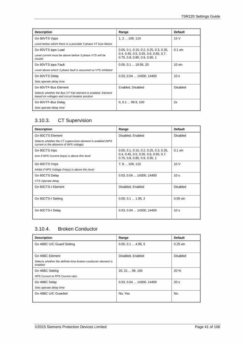
7SR220 Settings Guide
©2015 Siemens Protection Devices Limited Page 41 of 106
Description Range Default
Gn 60VTS Vpps
Level below which there is a possible 3 phase VT fuse failure
1, 2 ... 109, 110 15 V
Gn 60VTS Ipps Load
Level current must be above before 3 phase VTS will beissued
0.05, 0.1, 0.15, 0.2, 0.25, 0.3, 0.35,0.4, 0.45, 0.5, 0.55, 0.6, 0.65, 0.7,0.75, 0.8, 0.85, 0.9, 0.95, 1
0.1 xIn
Gn 60VTS Ipps Fault
Level above which 3 phase fault is assumed so VTS inhibited
0.05, 0.1 ... 19.95, 20 10 xIn
Gn 60VTS Delay
Sets operate delay time
0.03, 0.04 ... 14300, 14400 10 s
Gn 60VTF-Bus Element
Selects whether the Bus VT Fail element is enabled. Elementbased on voltages and circuit breaker position
Enabled, Disabled Disabled
Gn 60VTF-Bus Delay
Sets operate delay time
0, 0.1 ... 99.9, 100 2s
3.10.3. CT Supervision
Description Range Default
Gn 60CTS Element
Selects whether the CT supervision element is enabled (NPScurrent in the absence of NPS voltage)
Disabled, Enabled Disabled
Gn 60CTS Inps
Arm if NPS Current (Inps) is above this level
0.05, 0.1, 0.15, 0.2, 0.25, 0.3, 0.35,0.4, 0.45, 0.5, 0.55, 0.6, 0.65, 0.7,0.75, 0.8, 0.85, 0.9, 0.95, 1
0.1 xIn
Gn 60CTS Vnps
Inhibit if NPS Voltage (Vnps) is above this level
7, 8 ... 109, 110 10 V
Gn 60CTS Delay
CTS Operate delay
0.03, 0.04 ... 14300, 14400 10 s
Gn 60CTS-I Element Disabled, Enabled Disabled
Gn 60CTS-I Setting 0.05, 0.1 ... 1.95, 2 0.05 xIn
Gn 60CTS-I Delay 0.03, 0.04 ... 14300, 14400 10 s
3.10.4. Broken Conductor
Description Range Default
Gn 46BC U/C Guard Setting 0.05, 0.1 ... 4.95, 5 0.25 xIn
Gn 46BC Element
Selects whether the definite time broken conductor element isenabled
Disabled, Enabled Disabled
Gn 46BC Setting
NPS Current to PPS Current ratio
20, 21 ... 99, 100 20 %
Gn 46BC Delay
Sets operate delay time
0.03, 0.04 ... 14300, 14400 20 s
Gn 46BC U/C Guarded No, Yes No

7SR220 Settings Guide
Page 42 of 106 © 2013 Siemens Protection Devices Limited
3.10.5. Trip CCT Supervision
Description Range Default
Gn 74TCS-1
Selects whether the trip circuit supervision element 74TCS-1is enabled
Disabled, Enabled Disabled
Gn 74TCS-1 Delay
Time delay before trip circuit supervision operates
0, 0.02 ... 59.98, 60 0.4 s
Gn 74TCS-2
Selects whether the trip circuit supervision element 74TCS-2is enabled
Disabled, Enabled Disabled
Gn 74TCS-2 Delay
Time delay before trip circuit supervision operates
0, 0.02 ... 59.98, 60 0.4 s
Gn 74TCS-3
Selects whether the trip circuit supervision element 74TCS-3is enabled
Disabled, Enabled Disabled
Gn 74TCS-3 Delay
Time delay before trip circuit supervision operates
0, 0.02 ... 59.98, 60 0.4 s
3.10.6. Close CCT Supervision
Description Range Default
Gn 74CCS-1
Selects whether the trip circuit supervision element 74CCS-1is enabled
Disabled, Enabled Disabled
Gn 74CCS-1 Delay
Time delay before trip circuit supervision operates
0, 0.02 ... 59.98, 60 0.4 s
Gn 74CCS-2
Selects whether the trip circuit supervision element 74CCS-2is enabled
Disabled, Enabled Disabled
Gn 74CCS-2 Delay
Time delay before trip circuit supervision operates
0, 0.02 ... 59.98, 60 0.4 s
Gn 74CCS-3
Selects whether the trip circuit supervision element 74CCS-3is enabled
Disabled, Enabled Disabled
Gn 74CCS-3 Delay
Time delay before trip circuit supervision operates
0, 0.02 ... 59.98, 60 0.4 s
3.10.7. Inrush Detector
Description Range Default
Gn 81HBL2 Element
Selects whether the phase inrush detector 81HBL2 is enabled
Disabled, Enabled Disabled
Gn 81HBL2 Bias
Selects the bias method used for magnetising inrush. Phase –Segregated, each phase blocks itself. Cross – Blocked, eachphase can block the operation of other phases. Sum - OfSquares, each phase blocks itself using the square root of thesum of squares of the 2nd harmonic.
Phase, Cross, Sum Cross
Gn 81HBL2 Setting
The magnetising inrush detector operates when the 2ndharmonic current exceeds a set percentage of the fundamentalcurrent
0.1, 0.11 ... 0.49, 0.5 0.2 xI

7SR220 Settings Guide
©2015 Siemens Protection Devices Limited Page 43 of 106
3.10.8. Load Blinder3.10.8.1. 21LB-3P
Description Range Default
Gn 21LB-3P Angle +ve
Selects the boundary region.
5 degrees to 85 degrees 20 Degrees
Gn 21LB-3P Angle -ve
Selects the boundary region.
5 degrees to 85 degrees 20 Degrees
Gn 21LB-3P Impedance
Selects the impedance of the region.
1, 1.1,...50, 50.5, 51...100 Ohms 10 Ohms
Gn 21LB-3P VPPS
Sets the level of 21LB-3P VPPS setting
1, 1.5 ...110 V 50 V
Gn 21LB-3P INPS
Sets the level of 21LB-3P INPS setting.
0.05, 0.1 ... 0.45, 5 0.5 xI
3.10.8.2. 21LB-1P
Description Range Default
Gn 21LB-1P Angle +ve
Selects the boundary region.
5 degrees to 85 degrees 20 Degrees
Gn 21LB-1P Angle -ve
Selects the boundary region.
5 degrees to 85 degrees 20 Degrees
Gn 21LB-1P Impedance
Selects the impedance of the region.
1, 1.1,...50, 50.5, 51...100 Ohms 10 Ohms
Gn 21LB-1P VPPS
Sets the level of 21LB-1P VPPS setting
1, 1.5 ...110 V 50 V
Gn 21LB-1P IZPS
Sets the level of 21LB-1P ZNPS setting.
0.05, 0.1 ... 0.45, 5 0.5 xI
3.11. Control & Logic
3.11.1. Autoreclose Prot’n
Description Range Default
Gn 79 P/F Inst Trips
Selects which phase fault protection elements are classed asInstantaneous elements and start an autoreclose sequence.These will be blocked from operating during Delayedautoreclose sequences. See autoreclose section of manual fordetail of what elements can cause only Delayed protection tobe used.
Combination of ( 51-1, 51-2, 51-3,51-4, 50-1, 50-2, 50-3, 50-4 )
--------
Gn 79 E/F Inst Trips
Selects which earth fault protection elements are classed asInstantaneous elements and start an autoreclose sequence.These will be blocked from operating during Delayedautoreclose sequences. See autoreclose section of manual fordetail of what elements can cause only Delayed protection tobe used.
Combination of ( 51N-1, 51N-2,51N-3, 51N-4, 50N-1, 50N-2, 50N-3, 50N-4, 51G-1, 51G-2, 51G-3,51G-4, 50G-1, 50G-2, 50G-3, 50G-4 )
----------------
Gn 79 SEF Inst Trips
Selects which sensitive earth fault protection elements areclassed as Instantaneous elements and start an autoreclosesequence. These will be blocked from operating duringDelayed autoreclose sequences. See autoreclose section ofmanual for detail of what elements can cause only Delayedprotection to be used.
Combination of ( 51SEF-1, 51SEF-2, 51SEF-3, 51SEF-4, 50SEF-1,50SEF-2, 50SEF-3, 50SEF-4 )
--------

7SR220 Settings Guide
Page 44 of 106 © 2013 Siemens Protection Devices Limited
Description Range Default
Gn 79 P/F Delayed Trips
Selects which phase fault protection are classed as Delayedelements, any selected elements operating will start anautoreclose sequence.
Combination of ( 51-1, 51-2, 51-3,51-4, 50-1, 50-2, 50-3, 50-4 )
51-1, 51-2, 51-3,51-4, 50-1, 50-2,50-3, 50-4
Gn 79 E/F Delayed Trips
Selects which earth fault protection are classed as Delayedelements, any selected elements operating will start anautoreclose sequence.
Combination of ( 51N-1, 51N-2,51N-3, 51N-4, 50N-1, 50N-2, 50N-3, 50N-4, 51G-1, 51G-2, 51G-3,51G-4, 50G-1, 50G-2, 50G-3, 50G-4 )
51N-1, 51N-2,51N-3, 51N-4,50N-1, 50N-2,50N-3, 50N-4,51G-1, 51G-2,51G-3, 51G-4,50G-1, 50G-2,50G-3, 50G-4
Gn 79 SEF Delayed Trips
Selects which sensitive earth fault elements are classed asDelayed elements, any selected elements operating will startan autoreclose sequence.
Combination of ( 51SEF-1, 51SEF-2, 51SEF-3, 51SEF-4, 50SEF-1,50SEF-2, 50SEF-3, 50SEF-4 )
51SEF-1,51SEF-2,51SEF-3,51SEF-4,50SEF-1,50SEF-2,50SEF-3,50SEF-4
Gn 79 P/F HS Trips
Selects which phase fault elements are classed as High Setelements, any selected elements operating will start anautoreclose sequence.
Combination of ( 50-1, 50-2, 50-3,50-4 )
----
Gn 79 E/F HS Trips
Selects which earth fault elements are classed as High Setelements, any selected elements operating will start anautoreclose sequence.
Combination of ( 50N-1, 50N-2,50N-3, 50N-4, 50G-1, 50G-2, 50G-3, 50G-4 )
--------
3.11.2. Autoreclose Config
Description Range Default
Gn 79 Autoreclose
If disabled then all attempts to control the AR IN/OUT statuswill fail and the AR will be permanently Out Of Service. Whenenabled the AR IN/OUT state may be controlled via theCONTROL MODE menu option, via Binary Input or via localor remote communications.
Disabled, Enabled Enabled
Gn 79 Num Shots
Selects the number of auto-reclose attempts before theAutorecloser locks out
1, 2, 3, 4 1
Gn 79 Retry Enable
Selects whether the Retry close functionality is enabled
Disabled, Enabled Disabled
Gn 79 Retry Attempts
Selects the number of retries allowed per shot
0, 1, 2, 3, 4, 5, 6, 7, 8, 9, 10 1
Gn 79 Retry Interval
Time delay between retries
0, 1 ... 599, 600 60 s
Gn 79 Reclose Blocked Delay
Specifies the maximum time that the Autorecloser can beblocked before proceeding to the lockout state. (NOTE: Theblock delay timer only starts after the Deadtime.)
0, 1 ... 599, 600 60 s
Gn 79 Sequence Fail Timer
Time before lockout occurs on an incomplete reclosesequence. (i.e Trip & starter conditions have not been clearedafter Sequence Fail Time.)
0, 1 ... 599, 600 60 s
Gn 79 Sequence Co-ord
Selects whether Sequence co-ordination functionality is usedor not.
Disabled, Enabled Enabled

7SR220 Settings Guide
©2015 Siemens Protection Devices Limited Page 45 of 106
Description Range Default
Gn 79 Cold Load Action
Selects whether whist Cold Load is active the relay willperform only Delayed Trips or not.
Off, Delayed Off
3.11.2.1. P/F Shots
Description Range Default
Gn 79 P/F Prot'n Trip 1
Selects whether the first phase fault trip is Instantaneous(Fast) or Delayed. When set to Delayed all P/F Inst Trips willbe Inhibited for this shot.
Inst, Delayed Inst
Gn 79 P/F Deadtime 1
Time period between the fault being cleared and the closepulse being issued
0, 0.1 ... 14300, 14400 5 s
Gn 79 P/F Prot'n Trip 2
Selects whether the second phase fault trip is Instantaneous(Fast) or Delayed. When set to Delayed all P/F Inst Trips willbe Inhibited for this shot.
Inst, Delayed Inst
Gn 79 P/F Deadtime 2
Time period between the fault being cleared and the closepulse being issued
0, 0.1 ... 14300, 14400 5 s
Gn 79 P/F Prot'n Trip 3
Selects whether the third phase fault trip is Instantaneous(Fast) or Delayed. When set to Delayed all P/F Inst Trips willbe Inhibited for this shot.
Inst, Delayed Delayed
Gn 79 P/F Deadtime 3
Time period between the fault being cleared and the closepulse being issued
0, 0.1 ... 14300, 14400 5 s
Gn 79 P/F Prot'n Trip 4
Selects whether the fourth phase fault trip is Instantaneous(Fast) or Delayed. When set to Delayed all P/F Inst Trips willbe Inhibited for this shot.
Inst, Delayed Delayed
Gn 79 P/F Deadtime 4
Time period between the fault being cleared and the closepulse being issued
0, 0.1 ... 14300, 14400 5 s
Gn 79 P/F Prot'n Trip 5
Selects whether the fifth phase fault trip is Instantaneous(Fast) or Delayed. When set to Delayed all P/F Inst Trips willbe Inhibited for this shot.
Inst, Delayed Delayed
Gn 79 P/F HS Trips To Lockout
Selects how many High Set trips are allowed before going toLockout
1, 2, 3, 4, 5 5
Gn 79 P/F Delayed Trips To Lockout
Selects how many Delayed trips are allowed before going toLockout
1, 2, 3, 4, 5 5
3.11.2.2. E/F Shots
Description Range Default
Gn 79 E/F Prot'n Trip 1
Selects whether the first earth fault trip is Instantaneous (Fast)or Delayed. When set to Delayed all E/F Inst Trips will beInhibited for this shot.
Inst, Delayed Inst
Gn 79 E/F Deadtime 1
Time period between the fault being cleared and the closepulse being issued
0, 0.1 ... 14300, 14400 5 s
Gn 79 E/F Prot'n Trip 2
Selects whether the second earth fault trip is Instantaneous(Fast) or Delayed. When set to Delayed all E/F Inst Trips willbe Inhibited for this shot.
Inst, Delayed Inst

7SR220 Settings Guide
Page 46 of 106 © 2013 Siemens Protection Devices Limited
Description Range Default
Gn 79 E/F Deadtime 2
Time period between the fault being cleared and the closepulse being issued
0, 0.1 ... 14300, 14400 5 s
Gn 79 E/F Prot'n Trip 3
Selects whether the third earth fault trip is Instantaneous (Fast)or Delayed. When set to Delayed all E/F Inst Trips will beInhibited for this shot.
Inst, Delayed Delayed
Gn 79 E/F Deadtime 3
Time period between the fault being cleared and the closepulse being issued
0, 0.1 ... 14300, 14400 5 s
Gn 79 E/F Prot'n Trip 4
Selects whether the fourth earth fault trip is Instantaneous(Fast) or Delayed. When set to Delayed all E/F Inst Trips willbe Inhibited for this shot.
Inst, Delayed Delayed
Gn 79 E/F Deadtime 4
Time period between the fault being cleared and the closepulse being issued
0, 0.1 ... 14300, 14400 5 s
Gn 79 E/F Prot'n Trip 5
Selects whether the fifth earth fault trip is Instantaneous (Fast)or Delayed. When set to Delayed all E/F Inst Trips will beInhibited for this shot.
Inst, Delayed Delayed
Gn 79 E/F HS Trips To Lockout
Selects how many High Set trips are allowed before going toLockout
1, 2, 3, 4, 5 5
Gn 79 E/F Delayed Trips To Lockout
Selects how many Delayed trips are allowed before going toLockout
1, 2, 3, 4, 5 5
3.11.2.3. SEF Shots
Description Range Default
Gn 79 SEF Prot'n Trip 1
Selects whether the first sensitive earth fault trip isInstantaneous or Delayed. When set to Delayed all SEF InstTrips will be Inhibited for this shot.
Inst, Delayed Inst
Gn 79 SEF Deadtime 1
Time period between the fault being cleared and the closepulse being issued
0, 0.1 ... 14300, 14400 5 s
Gn 79 SEF Prot'n Trip 2
Selects whether the second sensitive earth fault trip isInstantaneous or Delayed. When set to Delayed all SEF InstTrips will be Inhibited for this shot.
Inst, Delayed Inst
Gn 79 SEF Deadtime 2
Time period between the fault being cleared and the closepulse being issued
0, 0.1 ... 14300, 14400 5 s
Gn 79 SEF Prot'n Trip 3
Selects whether the third sensitive earth fault trip isInstantaneous or Delayed. When set to Delayed all SEF InstTrips will be Inhibited for this shot.
Inst, Delayed Delayed
Gn 79 SEF Deadtime 3
Time period between the fault being cleared and the closepulse being issued
0, 0.1 ... 14300, 14400 5 s
Gn 79 SEF Prot'n Trip 4
Selects whether the fourth sensitive earth fault trip isInstantaneous or Delayed. When set to Delayed all SEF InstTrips will be Inhibited for this shot.
Inst, Delayed Delayed
Gn 79 SEF Deadtime 4
Time period between the fault being cleared and the closepulse being issued
0, 0.1 ... 14300, 14400 5 s

7SR220 Settings Guide
©2015 Siemens Protection Devices Limited Page 47 of 106
Description Range Default
Gn 79 SEF Prot'n Trip 5
Selects whether the fifth sensitive earth fault trip isInstantaneous or Delayed. When set to Delayed all SEF InstTrips will be Inhibited for this shot.
Inst, Delayed Delayed
Gn 79 SEF Delayed Trips To Lockout
Selects how many Delayed trips are allowed before going toLockout
1, 2, 3, 4, 5 5
3.11.2.4. Extern Shots
Description Range Default
Gn 79 Extern Prot'n Trip 1
Selects whether the first external trip is Instantaneous orDelayed
Not Blocked, Blocked Not Blocked
Gn 79 Extern Deadtime 1
Time period between the fault being cleared and the closepulse being issued
0, 0.1 ... 14300, 14400 5 s
Gn 79 Extern Prot'n Trip 2
Selects whether the second external trip is Instantaneous orDelayed
Not Blocked, Blocked Not Blocked
Gn 79 Extern Deadtime 2
Time period between the fault being cleared and the closepulse being issued
0, 0.1 ... 14300, 14400 5 s
Gn 79 Extern Prot'n Trip 3
Selects whether the third external trip is Instantaneous orDelayed
Not Blocked, Blocked Not Blocked
Gn 79 Extern Deadtime 3
Time period between the fault being cleared and the closepulse being issued
0, 0.1 ... 14300, 14400 5 s
Gn 79 Extern Prot'n Trip 4
Selects whether the fourth external trip is Instantaneous orDelayed
Not Blocked, Blocked Not Blocked
Gn 79 Extern Deadtime 4
Time period between the fault being cleared and the closepulse being issued
0, 0.1 ... 14300, 14400 5 s
Gn 79 Extern Prot'n Trip 5
Selects whether the fifth external trip is Instantaneous orDelayed
Not Blocked, Blocked Not Blocked
Gn 79 Extern Trips To Lockout
Selects how many external trips are allowed before going toLockout
1, 2, 3, 4, 5 5
3.11.3. Synchronising Check
Description Range Default
Gn 25 Sync Voltages Van, Vbn, Vcn, Vab, Vbc, Vca Vbn
Gn 25 Dead Line 0 % to 150 % 20 %
Gn 25 Live Line 0 % to 150 % 90 %
Gn 25 Dead Bus 0 % to 150 % 20 %
Gn 25 Live Bus 0 % to 150 % 90 %
Gn 25 Line U/V Disabled, Enabled Enabled
Gn 25 Line Undervolts 0 % to 150 % 90%
Gn 25 Bus U/V Disabled, Enabled Enabled
Gn 25 Bus Undervolts 0 % to 150 % 90%
Gn 25 Voltage Diff Disabled, Enabled Enabled

7SR220 Settings Guide
Page 48 of 106 © 2013 Siemens Protection Devices Limited
Description Range Default
Gn 25 Volt Differential 0 % to 100 % 10%
Gn 25 Check Sync Disabled, Enabled Enabled
Gn 25 Check Sync Angle 0 Deg to 90 Deg 20 Deg
Gn 25 Check Sync Slip Freq Disabled, Enabled Enabled
Gn 25 Check Sync Slip 0 Hz to 2 Hz 0.05 Hz
Gn 25 Check Sync Timer 0 s to 100 s 2 s
Gn 25 System Split Mode Phase, Slip Phase
Gn 25 Split Angle 0 Deg to 180 Deg 175 Deg
Gn 25 Split Slip 0 Hz to 2 Hz 0.02 Hz
Gn 25 System Sync Disabled, Enabled Enabled
Gn 25 System Sync Angle 0 Deg to 90 Deg 10 Deg
Gn 25 System Sync Slip 0 Hz to 2 Hz 0.125 Hz
Gn 25 System Sync Timer 0 s to 100 s 0.2 s
Gn 25 Close On Zero Disabled, Enabled Enabled
Gn 25 COZ Slip Freq 0 Hz to 2 Hz 0.125 Hz
Gn 25 CB Close Time 0 ms to 900 ms 60 ms
Gn 25 DAR Split Mode CS, SS, COZ, LO CS
Gn 25 MC Split Mode CS, SS, COZ CS
3.11.4. Manual CB Control
Description Range Default
Gn Line Check Trip
Selects whether line check trip is enabled, if enabled no ARsequence initiated
Disabled, Enabled Enabled
Gn P/F Line Check Trip
Selects whether a phase fault line check trip is Instantaneous(Fast) or Delayed. When set to Delayed all P/F Inst Trips willbe Inhibited for this shot.
Inst, Delayed Inst
Gn E/F Line Check Trip
Selects whether an earth fault line check trip is Instantaneousor Delayed. When set to Delayed all E/F Inst Trips will beInhibited for this shot.
Inst, Delayed Inst
Gn SEF Line Check Trip
Selects whether a sensitive earth fault line check trip isInstantaneous or Delayed. When set to Delayed all SEF InstTrips will be Inhibited for this shot.
Inst, Delayed Inst
Gn Extern Line Check Trip
Selects whether an external line check trip is Instantaneous(Fast) or Delayed
Not Blocked, Blocked Not Blocked
Gn Close CB Delay
Delay between a Close CB control being received and theClose CB contacts being operated to allow operator walkaway.
0, 0.1 ... 899, 900 10 s
Gn Blocked Close Delay
Selects the maximum time that the manual Close CB may beblocked by interlocking before the command or control iscancelled. The relay will signal “Blocked by Interlocking”.
0, 1 ... 599, 600 5 s
Gn Open CB Delay
Delay between an Open CB control being received and theOpen CB contacts being operated.
0, 0.1 ... 899, 900 10 s
Gn CB Controls Latched
Selects whether Binary Input triggers of Close CB and OpenCB are latched.
Latch, Reset Latch

7SR220 Settings Guide
©2015 Siemens Protection Devices Limited Page 49 of 106
3.11.5. Circuit Breaker
Description Range Default
Gn Close CB Pulse
Specifies the duration of the circuit breaker close pulse
0, 0.1 ... 19.9, 20 2 s
Gn Reclaim Timer
The period of time after a CB has closed and remained closedbefore the reclosure is deemed to be successful and the AR isre-initialised. If the CB remains open at the end of the reclaimtime then the AR goes to lockout.
0, 1 ... 599, 600 2 s
Gn Minimum LO Delay 0, 1 ... 599, 600 2 s
Gn Reset LO By Timer Disabled, Enabled Enabled
Gn CB Control Trip Time Disabled, Enabled Enabled
Gn Trip Time Alarm
An alarm is issued when the Trip time is exceeded
0, 0.01 ... 1.99, 2 0.2 s
Gn Trip Time Adjust
Adjustment to take into account any binary input delays forTrip Time Alarm
0, 0.005 ... 1.995, 2 0.015 s
Gn CB Travel Alarm
Selects the maximum time that the CB should take to eitherOpen or Close before a failure is recorded.
0.01, 0.02 ... 1.99, 2 1 s
Gn Open CB Pulse
Selects the maximum time of the Open CB pulse. If the CB isnot closed when this timer expires then an alarm will be raisedto signify failure to close.
0.1, 0.2, 0.3, 0.4, 0.5, 0.6, 0.7, 0.8,0.9, 1, 1.1, 1.2, 1.3, 1.4, 1.5, 1.6,1.7, 1.8, 1.9, 2
1 s
Gn CB DBI Delay
Selects the Delay before relay goes to Lockout following asimultaneous Open and Close condition indication.
0, 0.01, ... 1.1, 1.11 ... 2 0 s
3.11.6. QUICK LOGIC
Description Range Default
Quick Logic
Enable or Disable all logic equations
Disabled, Enabled Disabled
E1 Equation
Enable or Disable logic equation E1
Disabled, Enabled Disabled
E1
Specify logic equations of the form En =<Operand><Operator><Operand>using thefollowing:0123456789=Digit() = Parenthesis! = NOT operation.= AND operation^ = EXCLUSIVE OR operationE(followed by adigit) = Equation numberF (Followed by a digit) = Function KeynumberI(Followed by a digit) = Binary Input numberL(Followedby a digit) = LED numberO(Followed by a digit) = output relaynumberV(Followed by a digit) =Virtual Input/Outputnumber.ExamplesMake a function key LED toggle whenfunction key is pressed (requires E1 to drive L11 in outputmatrix)E1 = F3^L11
(20 Character String)
E1 Pick-up Delay
Time before equation output operates, after equation satisfied
0, 0.01 ... 14300, 14400 0 s
E1 Drop-off Delay
Time before equation output resets, after equation nolongersatisfied
0, 0.01 ... 14300, 14400 0 s

7SR220 Settings Guide
Page 50 of 106 © 2013 Siemens Protection Devices Limited
Description Range Default
E1 Counter Target
Select number of times equation must be satisfied beforeequation output operates
1, 2 ... 998, 999 1
E1 Counter Reset Mode
Select type of counter reset mode
Off, Multi-shot, Single-shot Off
E1 Counter Reset Time
Select counter reset time
0, 0.01 ... 14300, 14400 0 s
E2 Equation
Enable or Disable logic equation E2
Disabled, Enabled Disabled
E2
Specify logic equations of the form En =<Operand><Operator><Operand>using thefollowing:0123456789=Digit() = Parenthesis! = NOT operation.= AND operation^ = EXCLUSIVE OR operationE(followed by adigit) = Equation numberF (Followed by a digit) = Function KeynumberI(Followed by a digit) = Binary Input numberL(Followedby a digit) = LED numberO(Followed by a digit) = output relaynumberV(Followed by a digit) =Virtual Input/Outputnumber.ExamplesMake a function key LED toggle whenfunction key is pressed (requires E1 to drive L11 in outputmatrix)E1 = F3^L11
(20 Character String)
E2 Pick-up Delay
Time before equation output operates, after equation satisfied
0, 0.01 ... 14300, 14400 0 s
E2 Drop-off Delay
Time before equation output resets, after equation nolongersatisfied
0, 0.01 ... 14300, 14400 0 s
E2 Counter Target
Select number of times equation must be satisfied beforeequation output operates
1, 2 ... 998, 999 1
E2 Counter Reset Mode
Select type of counter reset mode
Off, Multi-shot, Single-shot Off
E2 Counter Reset Time
Select counter reset time
0, 0.01 ... 14300, 14400 0 s
E3 Equation
Enable or Disable logic equation E3
Disabled, Enabled Disabled
E3
Specify logic equations of the form En =<Operand><Operator><Operand>using thefollowing:0123456789=Digit() = Parenthesis! = NOT operation.= AND operation^ = EXCLUSIVE OR operationE(followed by adigit) = Equation numberF (Followed by a digit) = Function KeynumberI(Followed by a digit) = Binary Input numberL(Followedby a digit) = LED numberO(Followed by a digit) = output relaynumberV(Followed by a digit) =Virtual Input/Outputnumber.ExamplesMake a function key LED toggle whenfunction key is pressed (requires E1 to drive L11 in outputmatrix)E1 = F3^L11
(20 Character String)
E3 Pick-up Delay
Time before equation output operates, after equation satisfied
0, 0.01 ... 14300, 14400 0 s
E3 Drop-off Delay
Time before equation output resets, after equation nolongersatisfied
0, 0.01 ... 14300, 14400 0 s
E3 Counter Target
Select number of times equation must be satisfied beforeequation output operates
1, 2 ... 998, 999 1
E3 Counter Reset Mode
Select type of counter reset mode
Off, Multi-shot, Single-shot Off
E3 Counter Reset Time
Select counter reset time
0, 0.01 ... 14300, 14400 0 s

7SR220 Settings Guide
©2015 Siemens Protection Devices Limited Page 51 of 106
Description Range Default
E4 Equation
Enable or Disable logic equation E4
Disabled, Enabled Disabled
E4
Specify logic equations of the form En =<Operand><Operator><Operand>using thefollowing:0123456789=Digit() = Parenthesis! = NOT operation.= AND operation^ = EXCLUSIVE OR operationE(followed by adigit) = Equation numberF (Followed by a digit) = Function KeynumberI(Followed by a digit) = Binary Input numberL(Followedby a digit) = LED numberO(Followed by a digit) = output relaynumberV(Followed by a digit) =Virtual Input/Outputnumber.ExamplesMake a function key LED toggle whenfunction key is pressed (requires E1 to drive L11 in outputmatrix)E1 = F3^L11
(20 Character String)
E4 Pick-up Delay
Time before equation output operates, after equation satisfied
0, 0.01 ... 14300, 14400 0 s
E4 Drop-off Delay
Time before equation output resets, after equation nolongersatisfied
0, 0.01 ... 14300, 14400 0 s
E4 Counter Target
Select number of times equation must be satisfied beforeequation output operates
1, 2 ... 998, 999 1
E4 Counter Reset Mode
Select type of counter reset mode
Off, Multi-shot, Single-shot Off
E4 Counter Reset Time
Select counter reset time
0, 0.01 ... 14300, 14400 0 s
E5 Equation
Enable or Disable logic equation E5
Disabled, Enabled Disabled
E5
Specify logic equations of the form En =<Operand><Operator><Operand>using thefollowing:0123456789=Digit() = Parenthesis! = NOT operation.= AND operation^ = EXCLUSIVE OR operationE(followed by adigit) = Equation numberF (Followed by a digit) = Function KeynumberI(Followed by a digit) = Binary Input numberL(Followedby a digit) = LED numberO(Followed by a digit) = output relaynumberV(Followed by a digit) =Virtual Input/Outputnumber.ExamplesMake a function key LED toggle whenfunction key is pressed (requires E1 to drive L11 in outputmatrix)E1 = F3^L11
(20 Character String)
E5 Pick-up Delay
Time before equation output operates, after equation satisfied
0, 0.01 ... 14300, 14400 0 s
E5 Drop-off Delay
Time before equation output resets, after equation nolongersatisfied
0, 0.01 ... 14300, 14400 0 s
E5 Counter Target
Select number of times equation must be satisfied beforeequation output operates
1, 2 ... 998, 999 1
E5 Counter Reset Mode
Select type of counter reset mode
Off, Multi-shot, Single-shot Off
E5 Counter Reset Time
Select counter reset time
0, 0.01 ... 14300, 14400 0 s
E6 Equation
Enable or Disable logic equation E6
Disabled, Enabled Disabled

7SR220 Settings Guide
Page 52 of 106 © 2013 Siemens Protection Devices Limited
Description Range Default
E6
Specify logic equations of the form En =<Operand><Operator><Operand>using thefollowing:0123456789=Digit() = Parenthesis! = NOT operation.= AND operation^ = EXCLUSIVE OR operationE(followed by adigit) = Equation numberF (Followed by a digit) = Function KeynumberI(Followed by a digit) = Binary Input numberL(Followedby a digit) = LED numberO(Followed by a digit) = output relaynumberV(Followed by a digit) =Virtual Input/Outputnumber.ExamplesMake a function key LED toggle whenfunction key is pressed (requires E1 to drive L11 in outputmatrix)E1 = F3^L11
(20 Character String)
E6 Pick-up Delay
Time before equation output operates, after equation satisfied
0, 0.01 ... 14300, 14400 0 s
E6 Drop-off Delay
Time before equation output resets, after equation nolongersatisfied
0, 0.01 ... 14300, 14400 0 s
E6 Counter Target
Select number of times equation must be satisfied beforeequation output operates
1, 2 ... 998, 999 1
E6 Counter Reset Mode
Select type of counter reset mode
Off, Multi-shot, Single-shot Off
E6 Counter Reset Time
Select counter reset time
0, 0.01 ... 14300, 14400 0 s
E7 Equation
Enable or Disable logic equation E7
Disabled, Enabled Disabled
E7
Specify logic equations of the form En =<Operand><Operator><Operand>using thefollowing:0123456789=Digit() = Parenthesis! = NOT operation.= AND operation^ = EXCLUSIVE OR operationE(followed by adigit) = Equation numberF (Followed by a digit) = Function KeynumberI(Followed by a digit) = Binary Input numberL(Followedby a digit) = LED numberO(Followed by a digit) = output relaynumberV(Followed by a digit) =Virtual Input/Outputnumber.ExamplesMake a function key LED toggle whenfunction key is pressed (requires E1 to drive L11 in outputmatrix)E1 = F3^L11
(20 Character String)
E7 Pick-up Delay
Time before equation output operates, after equation satisfied
0, 0.01 ... 14300, 14400 0 s
E7 Drop-off Delay
Time before equation output resets, after equation nolongersatisfied
0, 0.01 ... 14300, 14400 0 s
E7 Counter Target
Select number of times equation must be satisfied beforeequation output operates
1, 2 ... 998, 999 1
E7 Counter Reset Mode
Select type of counter reset mode
Off, Multi-shot, Single-shot Off
E7 Counter Reset Time
Select counter reset time
0, 0.01 ... 14300, 14400 0 s
E8 Equation
Enable or Disable logic equation E8
Disabled, Enabled Disabled
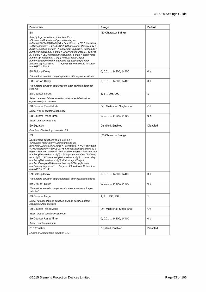
7SR220 Settings Guide
©2015 Siemens Protection Devices Limited Page 53 of 106
Description Range Default
E8
Specify logic equations of the form En =<Operand><Operator><Operand>using thefollowing:0123456789=Digit() = Parenthesis! = NOT operation.= AND operation^ = EXCLUSIVE OR operationE(followed by adigit) = Equation numberF (Followed by a digit) = Function KeynumberI(Followed by a digit) = Binary Input numberL(Followedby a digit) = LED numberO(Followed by a digit) = output relaynumberV(Followed by a digit) =Virtual Input/Outputnumber.ExamplesMake a function key LED toggle whenfunction key is pressed (requires E1 to drive L11 in outputmatrix)E1 = F3^L11
(20 Character String)
E8 Pick-up Delay
Time before equation output operates, after equation satisfied
0, 0.01 ... 14300, 14400 0 s
E8 Drop-off Delay
Time before equation output resets, after equation nolongersatisfied
0, 0.01 ... 14300, 14400 0 s
E8 Counter Target
Select number of times equation must be satisfied beforeequation output operates
1, 2 ... 998, 999 1
E8 Counter Reset Mode
Select type of counter reset mode
Off, Multi-shot, Single-shot Off
E8 Counter Reset Time
Select counter reset time
0, 0.01 ... 14300, 14400 0 s
E9 Equation
Enable or Disable logic equation E9
Disabled, Enabled Disabled
E9
Specify logic equations of the form En =<Operand><Operator><Operand>using thefollowing:0123456789=Digit() = Parenthesis! = NOT operation.= AND operation^ = EXCLUSIVE OR operationE(followed by adigit) = Equation numberF (Followed by a digit) = Function KeynumberI(Followed by a digit) = Binary Input numberL(Followedby a digit) = LED numberO(Followed by a digit) = output relaynumberV(Followed by a digit) =Virtual Input/Outputnumber.ExamplesMake a function key LED toggle whenfunction key is pressed (requires E1 to drive L11 in outputmatrix)E1 = F3^L11
(20 Character String)
E9 Pick-up Delay
Time before equation output operates, after equation satisfied
0, 0.01 ... 14300, 14400 0 s
E9 Drop-off Delay
Time before equation output resets, after equation nolongersatisfied
0, 0.01 ... 14300, 14400 0 s
E9 Counter Target
Select number of times equation must be satisfied beforeequation output operates
1, 2 ... 998, 999 1
E9 Counter Reset Mode
Select type of counter reset mode
Off, Multi-shot, Single-shot Off
E9 Counter Reset Time
Select counter reset time
0, 0.01 ... 14300, 14400 0 s
E10 Equation
Enable or Disable logic equation E10
Disabled, Enabled Disabled

7SR220 Settings Guide
Page 54 of 106 © 2013 Siemens Protection Devices Limited
Description Range Default
E10
Specify logic equations of the form En =<Operand><Operator><Operand>using thefollowing:0123456789=Digit() = Parenthesis! = NOT operation.= AND operation^ = EXCLUSIVE OR operationE(followed by adigit) = Equation numberF (Followed by a digit) = Function KeynumberI(Followed by a digit) = Binary Input numberL(Followedby a digit) = LED numberO(Followed by a digit) = output relaynumberV(Followed by a digit) =Virtual Input/Outputnumber.ExamplesMake a function key LED toggle whenfunction key is pressed (requires E1 to drive L11 in outputmatrix)E1 = F3^L11
(20 Character String)
E10 Pick-up Delay
Time before equation output operates, after equation satisfied
0, 0.01 ... 14300, 14400 0 s
E10 Drop-off Delay
Time before equation output resets, after equation nolongersatisfied
0, 0.01 ... 14300, 14400 0 s
E10 Counter Target
Select number of times equation must be satisfied beforeequation output operates
1, 2 ... 998, 999 1
E10 Counter Reset Mode
Select type of counter reset mode
Off, Multi-shot, Single-shot Off
E10 Counter Reset Time
Select counter reset time
0, 0.01 ... 14300, 14400 0 s
E11 Equation
Enable or Disable logic equation E11
Disabled, Enabled Disabled
E11
Specify logic equations of the form En =<Operand><Operator><Operand>using thefollowing:0123456789=Digit() = Parenthesis! = NOT operation.= AND operation^ = EXCLUSIVE OR operationE(followed by adigit) = Equation numberF (Followed by a digit) = Function KeynumberI(Followed by a digit) = Binary Input numberL(Followedby a digit) = LED numberO(Followed by a digit) = output relaynumberV(Followed by a digit) =Virtual Input/Outputnumber.ExamplesMake a function key LED toggle whenfunction key is pressed (requires E1 to drive L11 in outputmatrix)E1 = F3^L11
(20 Character String)
E11 Pick-up Delay
Time before equation output operates, after equation satisfied
0, 0.01 ... 14300, 14400 0 s
E11 Drop-off Delay
Time before equation output resets, after equation nolongersatisfied
0, 0.01 ... 14300, 14400 0 s
E11 Counter Target
Select number of times equation must be satisfied beforeequation output operates
1, 2 ... 998, 999 1
E11 Counter Reset Mode
Select type of counter reset mode
Off, Multi-shot, Single-shot Off
E11 Counter Reset Time
Select counter reset time
0, 0.01 ... 14300, 14400 0 s
E12 Equation
Enable or Disable logic equation E12
Disabled, Enabled Disabled

7SR220 Settings Guide
©2015 Siemens Protection Devices Limited Page 55 of 106
Description Range Default
E12
Specify logic equations of the form En =<Operand><Operator><Operand>using thefollowing:0123456789=Digit() = Parenthesis! = NOT operation.= AND operation^ = EXCLUSIVE OR operationE(followed by adigit) = Equation numberF (Followed by a digit) = Function KeynumberI(Followed by a digit) = Binary Input numberL(Followedby a digit) = LED numberO(Followed by a digit) = output relaynumberV(Followed by a digit) =Virtual Input/Outputnumber.ExamplesMake a function key LED toggle whenfunction key is pressed (requires E1 to drive L11 in outputmatrix)E1 = F3^L11
(20 Character String)
E12 Pick-up Delay
Time before equation output operates, after equation satisfied
0, 0.01 ... 14300, 14400 0 s
E12 Drop-off Delay
Time before equation output resets, after equation nolongersatisfied
0, 0.01 ... 14300, 14400 0 s
E12 Counter Target
Select number of times equation must be satisfied beforeequation output operates
1, 2 ... 998, 999 1
E12 Counter Reset Mode
Select type of counter reset mode
Off, Multi-shot, Single-shot Off
E12 Counter Reset Time
Select counter reset time
0, 0.01 ... 14300, 14400 0 s
E13 Equation
Enable or Disable logic equation E13
Disabled, Enabled Disabled
E13
Specify logic equations of the form En =<Operand><Operator><Operand>using thefollowing:0123456789=Digit() = Parenthesis! = NOT operation.= AND operation^ = EXCLUSIVE OR operationE(followed by adigit) = Equation numberF (Followed by a digit) = Function KeynumberI(Followed by a digit) = Binary Input numberL(Followedby a digit) = LED numberO(Followed by a digit) = output relaynumberV(Followed by a digit) =Virtual Input/Outputnumber.ExamplesMake a function key LED toggle whenfunction key is pressed (requires E1 to drive L11 in outputmatrix)E1 = F3^L11
(20 Character String)
E13 Pick-up Delay
Time before equation output operates, after equation satisfied
0, 0.01 ... 14300, 14400 0 s
E13 Drop-off Delay
Time before equation output resets, after equation nolongersatisfied
0, 0.01 ... 14300, 14400 0 s
E13 Counter Target
Select number of times equation must be satisfied beforeequation output operates
1, 2 ... 998, 999 1
E13 Counter Reset Mode
Select type of counter reset mode
Off, Multi-shot, Single-shot Off
E13 Counter Reset Time
Select counter reset time
0, 0.01 ... 14300, 14400 0 s
E14 Equation
Enable or Disable logic equation E14
Disabled, Enabled Disabled
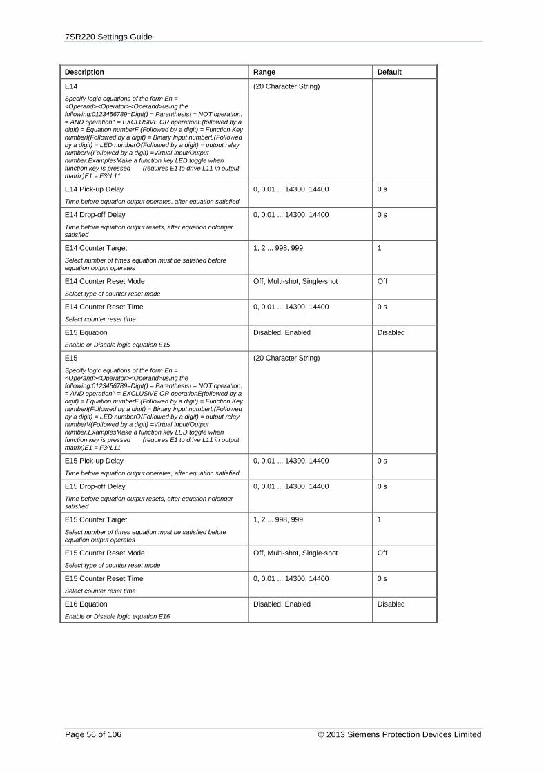
7SR220 Settings Guide
Page 56 of 106 © 2013 Siemens Protection Devices Limited
Description Range Default
E14
Specify logic equations of the form En =<Operand><Operator><Operand>using thefollowing:0123456789=Digit() = Parenthesis! = NOT operation.= AND operation^ = EXCLUSIVE OR operationE(followed by adigit) = Equation numberF (Followed by a digit) = Function KeynumberI(Followed by a digit) = Binary Input numberL(Followedby a digit) = LED numberO(Followed by a digit) = output relaynumberV(Followed by a digit) =Virtual Input/Outputnumber.ExamplesMake a function key LED toggle whenfunction key is pressed (requires E1 to drive L11 in outputmatrix)E1 = F3^L11
(20 Character String)
E14 Pick-up Delay
Time before equation output operates, after equation satisfied
0, 0.01 ... 14300, 14400 0 s
E14 Drop-off Delay
Time before equation output resets, after equation nolongersatisfied
0, 0.01 ... 14300, 14400 0 s
E14 Counter Target
Select number of times equation must be satisfied beforeequation output operates
1, 2 ... 998, 999 1
E14 Counter Reset Mode
Select type of counter reset mode
Off, Multi-shot, Single-shot Off
E14 Counter Reset Time
Select counter reset time
0, 0.01 ... 14300, 14400 0 s
E15 Equation
Enable or Disable logic equation E15
Disabled, Enabled Disabled
E15
Specify logic equations of the form En =<Operand><Operator><Operand>using thefollowing:0123456789=Digit() = Parenthesis! = NOT operation.= AND operation^ = EXCLUSIVE OR operationE(followed by adigit) = Equation numberF (Followed by a digit) = Function KeynumberI(Followed by a digit) = Binary Input numberL(Followedby a digit) = LED numberO(Followed by a digit) = output relaynumberV(Followed by a digit) =Virtual Input/Outputnumber.ExamplesMake a function key LED toggle whenfunction key is pressed (requires E1 to drive L11 in outputmatrix)E1 = F3^L11
(20 Character String)
E15 Pick-up Delay
Time before equation output operates, after equation satisfied
0, 0.01 ... 14300, 14400 0 s
E15 Drop-off Delay
Time before equation output resets, after equation nolongersatisfied
0, 0.01 ... 14300, 14400 0 s
E15 Counter Target
Select number of times equation must be satisfied beforeequation output operates
1, 2 ... 998, 999 1
E15 Counter Reset Mode
Select type of counter reset mode
Off, Multi-shot, Single-shot Off
E15 Counter Reset Time
Select counter reset time
0, 0.01 ... 14300, 14400 0 s
E16 Equation
Enable or Disable logic equation E16
Disabled, Enabled Disabled

7SR220 Settings Guide
©2015 Siemens Protection Devices Limited Page 57 of 106
Description Range Default
E16
Specify logic equations of the form En =<Operand><Operator><Operand>using thefollowing:0123456789=Digit() = Parenthesis! = NOT operation.= AND operation^ = EXCLUSIVE OR operationE(followed by adigit) = Equation numberF (Followed by a digit) = Function KeynumberI(Followed by a digit) = Binary Input numberL(Followedby a digit) = LED numberO(Followed by a digit) = output relaynumberV(Followed by a digit) =Virtual Input/Outputnumber.ExamplesMake a function key LED toggle whenfunction key is pressed (requires E1 to drive L11 in outputmatrix)E1 = F3^L11
(20 Character String)
E16 Pick-up Delay
Time before equation output operates, after equation satisfied
0, 0.01 ... 14300, 14400 0 s
E16 Drop-off Delay
Time before equation output resets, after equation nolongersatisfied
0, 0.01 ... 14300, 14400 0 s
E16 Counter Target
Select number of times equation must be satisfied beforeequation output operates
1, 2 ... 998, 999 1
E16 Counter Reset Mode
Select type of counter reset mode
Off, Multi-shot, Single-shot Off
E16 Counter Reset Time
Select counter reset time
0, 0.01 ... 14300, 14400 0 s
E16 Equation
Enable or Disable logic equation E16
Disabled, Enabled Disabled

7SR220 Settings Guide
Page 58 of 106 © 2013 Siemens Protection Devices Limited
3.12. Input Config
3.12.1. Input Matrix
Description Range Default
Inhibit 81HBL2
Selects which inputs inhibit the 81HLB2
Combination of ( BI1, BI2, BI3, BI4,BI5, BI6, BI7, BI8, BI9, BI10, BI11,BI12, BI13, V1, V2, V3, V4, V5, V6,V7, V8, V9, V10, V11, V12, V13,V14, V15, V16 )
-----------------------------
Inhibit Cold Load
Selects which inputs inhibit the Cold Load element
Combination of ( BI1, BI2, BI3, BI4,BI5, BI6, BI7, BI8, BI9, BI10, BI11,BI12, BI13, V1, V2, V3, V4, V5, V6,V7, V8, V9, V10, V11, V12, V13,V14, V15, V16 )
-----------------------------
Inhibit 51-1
Selects which inputs inhibit the 51-1 element
Combination of ( BI1, BI2, BI3, BI4,BI5, BI6, BI7, BI8, BI9, BI10, BI11,BI12, BI13, V1, V2, V3, V4, V5, V6,V7, V8, V9, V10, V11, V12, V13,V14, V15, V16 )
-----------------------------
Inhibit 51-2
Selects which inputs inhibit the 51-2 element
Combination of ( BI1, BI2, BI3, BI4,BI5, BI6, BI7, BI8, BI9, BI10, BI11,BI12, BI13, V1, V2, V3, V4, V5, V6,V7, V8, V9, V10, V11, V12, V13,V14, V15, V16 )
-----------------------------
Inhibit 51-3
Selects which inputs inhibit the 51-3 element
Combination of ( BI1, BI2, BI3, BI4,BI5, BI6, BI7, BI8, BI9, BI10, BI11,BI12, BI13, V1, V2, V3, V4, V5, V6,V7, V8, V9, V10, V11, V12, V13,V14, V15, V16 )
-----------------------------
Inhibit 51-4
Selects which inputs inhibit the 51-4 element
Combination of ( BI1, BI2, BI3, BI4,BI5, BI6, BI7, BI8, BI9, BI10, BI11,BI12, BI13, V1, V2, V3, V4, V5, V6,V7, V8, V9, V10, V11, V12, V13,V14, V15, V16 )
-----------------------------
Inhibit 50-1
Selects which inputs inhibit the 50-1 element
Combination of ( BI1, BI2, BI3, BI4,BI5, BI6, BI7, BI8, BI9, BI10, BI11,BI12, BI13, V1, V2, V3, V4, V5, V6,V7, V8, V9, V10, V11, V12, V13,V14, V15, V16 )
-----------------------------
Inhibit 50-2
Selects which inputs inhibit the 50-2 element
Combination of ( BI1, BI2, BI3, BI4,BI5, BI6, BI7, BI8, BI9, BI10, BI11,BI12, BI13, V1, V2, V3, V4, V5, V6,V7, V8, V9, V10, V11, V12, V13,V14, V15, V16 )
-----------------------------
Inhibit 50-3
Selects which inputs inhibit the 50-3 element
Combination of ( BI1, BI2, BI3, BI4,BI5, BI6, BI7, BI8, BI9, BI10, BI11,BI12, BI13, V1, V2, V3, V4, V5, V6,V7, V8, V9, V10, V11, V12, V13,V14, V15, V16 )
-----------------------------
Inhibit 50-4
Selects which inputs inhibit the 50-4 element
Combination of ( BI1, BI2, BI3, BI4,BI5, BI6, BI7, BI8, BI9, BI10, BI11,BI12, BI13, V1, V2, V3, V4, V5, V6,V7, V8, V9, V10, V11, V12, V13,V14, V15, V16 )
-----------------------------
Inhibit 51N-1
Selects which inputs inhibit the 51N-1 element
Combination of ( BI1, BI2, BI3, BI4,BI5, BI6, BI7, BI8, BI9, BI10, BI11,BI12, BI13, V1, V2, V3, V4, V5, V6,V7, V8, V9, V10, V11, V12, V13,V14, V15, V16 )
-----------------------------
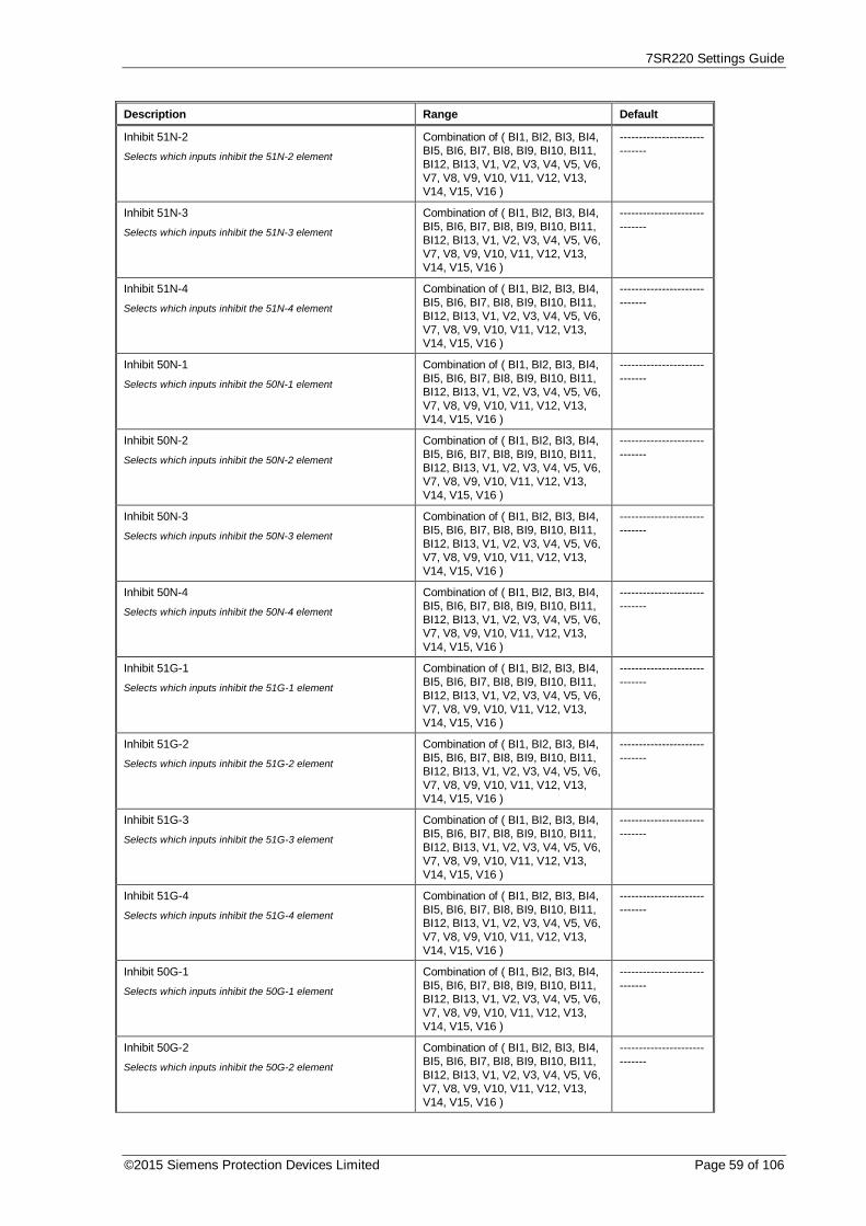
7SR220 Settings Guide
©2015 Siemens Protection Devices Limited Page 59 of 106
Description Range Default
Inhibit 51N-2
Selects which inputs inhibit the 51N-2 element
Combination of ( BI1, BI2, BI3, BI4,BI5, BI6, BI7, BI8, BI9, BI10, BI11,BI12, BI13, V1, V2, V3, V4, V5, V6,V7, V8, V9, V10, V11, V12, V13,V14, V15, V16 )
-----------------------------
Inhibit 51N-3
Selects which inputs inhibit the 51N-3 element
Combination of ( BI1, BI2, BI3, BI4,BI5, BI6, BI7, BI8, BI9, BI10, BI11,BI12, BI13, V1, V2, V3, V4, V5, V6,V7, V8, V9, V10, V11, V12, V13,V14, V15, V16 )
-----------------------------
Inhibit 51N-4
Selects which inputs inhibit the 51N-4 element
Combination of ( BI1, BI2, BI3, BI4,BI5, BI6, BI7, BI8, BI9, BI10, BI11,BI12, BI13, V1, V2, V3, V4, V5, V6,V7, V8, V9, V10, V11, V12, V13,V14, V15, V16 )
-----------------------------
Inhibit 50N-1
Selects which inputs inhibit the 50N-1 element
Combination of ( BI1, BI2, BI3, BI4,BI5, BI6, BI7, BI8, BI9, BI10, BI11,BI12, BI13, V1, V2, V3, V4, V5, V6,V7, V8, V9, V10, V11, V12, V13,V14, V15, V16 )
-----------------------------
Inhibit 50N-2
Selects which inputs inhibit the 50N-2 element
Combination of ( BI1, BI2, BI3, BI4,BI5, BI6, BI7, BI8, BI9, BI10, BI11,BI12, BI13, V1, V2, V3, V4, V5, V6,V7, V8, V9, V10, V11, V12, V13,V14, V15, V16 )
-----------------------------
Inhibit 50N-3
Selects which inputs inhibit the 50N-3 element
Combination of ( BI1, BI2, BI3, BI4,BI5, BI6, BI7, BI8, BI9, BI10, BI11,BI12, BI13, V1, V2, V3, V4, V5, V6,V7, V8, V9, V10, V11, V12, V13,V14, V15, V16 )
-----------------------------
Inhibit 50N-4
Selects which inputs inhibit the 50N-4 element
Combination of ( BI1, BI2, BI3, BI4,BI5, BI6, BI7, BI8, BI9, BI10, BI11,BI12, BI13, V1, V2, V3, V4, V5, V6,V7, V8, V9, V10, V11, V12, V13,V14, V15, V16 )
-----------------------------
Inhibit 51G-1
Selects which inputs inhibit the 51G-1 element
Combination of ( BI1, BI2, BI3, BI4,BI5, BI6, BI7, BI8, BI9, BI10, BI11,BI12, BI13, V1, V2, V3, V4, V5, V6,V7, V8, V9, V10, V11, V12, V13,V14, V15, V16 )
-----------------------------
Inhibit 51G-2
Selects which inputs inhibit the 51G-2 element
Combination of ( BI1, BI2, BI3, BI4,BI5, BI6, BI7, BI8, BI9, BI10, BI11,BI12, BI13, V1, V2, V3, V4, V5, V6,V7, V8, V9, V10, V11, V12, V13,V14, V15, V16 )
-----------------------------
Inhibit 51G-3
Selects which inputs inhibit the 51G-3 element
Combination of ( BI1, BI2, BI3, BI4,BI5, BI6, BI7, BI8, BI9, BI10, BI11,BI12, BI13, V1, V2, V3, V4, V5, V6,V7, V8, V9, V10, V11, V12, V13,V14, V15, V16 )
-----------------------------
Inhibit 51G-4
Selects which inputs inhibit the 51G-4 element
Combination of ( BI1, BI2, BI3, BI4,BI5, BI6, BI7, BI8, BI9, BI10, BI11,BI12, BI13, V1, V2, V3, V4, V5, V6,V7, V8, V9, V10, V11, V12, V13,V14, V15, V16 )
-----------------------------
Inhibit 50G-1
Selects which inputs inhibit the 50G-1 element
Combination of ( BI1, BI2, BI3, BI4,BI5, BI6, BI7, BI8, BI9, BI10, BI11,BI12, BI13, V1, V2, V3, V4, V5, V6,V7, V8, V9, V10, V11, V12, V13,V14, V15, V16 )
-----------------------------
Inhibit 50G-2
Selects which inputs inhibit the 50G-2 element
Combination of ( BI1, BI2, BI3, BI4,BI5, BI6, BI7, BI8, BI9, BI10, BI11,BI12, BI13, V1, V2, V3, V4, V5, V6,V7, V8, V9, V10, V11, V12, V13,V14, V15, V16 )
-----------------------------

7SR220 Settings Guide
Page 60 of 106 © 2013 Siemens Protection Devices Limited
Description Range Default
Inhibit 50G-3
Selects which inputs inhibit the 50G-3 element
Combination of ( BI1, BI2, BI3, BI4,BI5, BI6, BI7, BI8, BI9, BI10, BI11,BI12, BI13, V1, V2, V3, V4, V5, V6,V7, V8, V9, V10, V11, V12, V13,V14, V15, V16 )
-----------------------------
Inhibit 50G-4
Selects which inputs inhibit the 50G-4 element
Combination of ( BI1, BI2, BI3, BI4,BI5, BI6, BI7, BI8, BI9, BI10, BI11,BI12, BI13, V1, V2, V3, V4, V5, V6,V7, V8, V9, V10, V11, V12, V13,V14, V15, V16 )
-----------------------------
Inhibit 51SEF-1
Selects which inputs inhibit the 51SEF-1 element
Combination of ( BI1, BI2, BI3, BI4,BI5, BI6, BI7, BI8, BI9, BI10, BI11,BI12, BI13, V1, V2, V3, V4, V5, V6,V7, V8, V9, V10, V11, V12, V13,V14, V15, V16 )
-----------------------------
Inhibit 51SEF-2
Selects which inputs inhibit the 51SEF-2 element
Combination of ( BI1, BI2, BI3, BI4,BI5, BI6, BI7, BI8, BI9, BI10, BI11,BI12, BI13, V1, V2, V3, V4, V5, V6,V7, V8, V9, V10, V11, V12, V13,V14, V15, V16 )
-----------------------------
Inhibit 51SEF-3
Selects which inputs inhibit the 51SEF-3 element
Combination of ( BI1, BI2, BI3, BI4,BI5, BI6, BI7, BI8, BI9, BI10, BI11,BI12, BI13, V1, V2, V3, V4, V5, V6,V7, V8, V9, V10, V11, V12, V13,V14, V15, V16 )
-----------------------------
Inhibit 51SEF-4
Selects which inputs inhibit the 51SEF-4 element
Combination of ( BI1, BI2, BI3, BI4,BI5, BI6, BI7, BI8, BI9, BI10, BI11,BI12, BI13, V1, V2, V3, V4, V5, V6,V7, V8, V9, V10, V11, V12, V13,V14, V15, V16 )
-----------------------------
Inhibit 50SEF-1
Selects which inputs inhibit the 50SEF-1 element
Combination of ( BI1, BI2, BI3, BI4,BI5, BI6, BI7, BI8, BI9, BI10, BI11,BI12, BI13, V1, V2, V3, V4, V5, V6,V7, V8, V9, V10, V11, V12, V13,V14, V15, V16 )
-----------------------------
Inhibit 50SEF-2
Selects which inputs inhibit the 50SEF-2 element
Combination of ( BI1, BI2, BI3, BI4,BI5, BI6, BI7, BI8, BI9, BI10, BI11,BI12, BI13, V1, V2, V3, V4, V5, V6,V7, V8, V9, V10, V11, V12, V13,V14, V15, V16 )
-----------------------------
Inhibit 50SEF-3
Selects which inputs inhibit the 50SEF-3 element
Combination of ( BI1, BI2, BI3, BI4,BI5, BI6, BI7, BI8, BI9, BI10, BI11,BI12, BI13, V1, V2, V3, V4, V5, V6,V7, V8, V9, V10, V11, V12, V13,V14, V15, V16 )
-----------------------------
Inhibit 50SEF-4
Selects which inputs inhibit the 50SEF-4 element
Combination of ( BI1, BI2, BI3, BI4,BI5, BI6, BI7, BI8, BI9, BI10, BI11,BI12, BI13, V1, V2, V3, V4, V5, V6,V7, V8, V9, V10, V11, V12, V13,V14, V15, V16 )
-----------------------------
Inhibit 64H
Selects which inputs inhibit the 64H element
Combination of ( BI1, BI2, BI3, BI4,BI5, BI6, BI7, BI8, BI9, BI10, BI11,BI12, BI13, V1, V2, V3, V4, V5, V6,V7, V8, V9, V10, V11, V12, V13,V14, V15, V16 )
-----------------------------
Inhibit 46IT
Selects which inputs inhibit the 46IT element
Combination of ( BI1, BI2, BI3, BI4,BI5, BI6, BI7, BI8, BI9, BI10, BI11,BI12, BI13, V1, V2, V3, V4, V5, V6,V7, V8, V9, V10, V11, V12, V13,V14, V15, V16 )
-----------------------------
Inhibit 46DT
Selects which inputs inhibit the 46DT element
Combination of ( BI1, BI2, BI3, BI4,BI5, BI6, BI7, BI8, BI9, BI10, BI11,BI12, BI13, V1, V2, V3, V4, V5, V6,V7, V8, V9, V10, V11, V12, V13,V14, V15, V16 )
-----------------------------

7SR220 Settings Guide
©2015 Siemens Protection Devices Limited Page 61 of 106
Description Range Default
Inhibit 37-1
Selects which inputs inhibit the 37-1 element
Combination of ( BI1, BI2, BI3, BI4,BI5, BI6, BI7, BI8, BI9, BI10, BI11,BI12, BI13, V1, V2, V3, V4, V5, V6,V7, V8, V9, V10, V11, V12, V13,V14, V15, V16 )
-----------------------------
Inhibit 37-2
Selects which inputs inhibit the 37-2 element
Combination of ( BI1, BI2, BI3, BI4,BI5, BI6, BI7, BI8, BI9, BI10, BI11,BI12, BI13, V1, V2, V3, V4, V5, V6,V7, V8, V9, V10, V11, V12, V13,V14, V15, V16 )
-----------------------------
Inhibit 37G-1
Selects which inputs inhibit the 37G-1 element
Combination of ( BI1, BI2, BI3, BI4,BI5, BI6, BI7, BI8, BI9, BI10, BI11,BI12, BI13, V1, V2, V3, V4, V5, V6,V7, V8, V9, V10, V11, V12, V13,V14, V15, V16 )
-----------------------------
Inhibit 37G-2
Selects which inputs inhibit the 37G-2 element
Combination of ( BI1, BI2, BI3, BI4,BI5, BI6, BI7, BI8, BI9, BI10, BI11,BI12, BI13, V1, V2, V3, V4, V5, V6,V7, V8, V9, V10, V11, V12, V13,V14, V15, V16 )
-----------------------------
Inhibit 37SEF-1
Selects which inputs inhibit the 37SEF-1 element
Combination of ( BI1, BI2, BI3, BI4,BI5, BI6, BI7, BI8, BI9, BI10, BI11,BI12, BI13, V1, V2, V3, V4, V5, V6,V7, V8, V9, V10, V11, V12, V13,V14, V15, V16 )
-----------------------------
Inhibit 37SEF-2
Selects which inputs inhibit the 37SEF-2 element
Combination of ( BI1, BI2, BI3, BI4,BI5, BI6, BI7, BI8, BI9, BI10, BI11,BI12, BI13, V1, V2, V3, V4, V5, V6,V7, V8, V9, V10, V11, V12, V13,V14, V15, V16 )
-----------------------------
Inhibit 49
Selects which inputs inhibit the 49 thermal element
Combination of ( BI1, BI2, BI3, BI4,BI5, BI6, BI7, BI8, BI9, BI10, BI11,BI12, BI13, V1, V2, V3, V4, V5, V6,V7, V8, V9, V10, V11, V12, V13,V14, V15, V16 )
-----------------------------
Reset 49
Selects which inputs resets the 49 thermal model element
Combination of ( BI1, BI2, BI3, BI4,BI5, BI6, BI7, BI8, BI9, BI10, BI11,BI12, BI13, V1, V2, V3, V4, V5, V6,V7, V8, V9, V10, V11, V12, V13,V14, V15, V16 )
-----------------------------
Inhibit 27/59-1
Selects which inputs inhibit the 27/59-1 element
Combination of ( BI1, BI2, BI3, BI4,BI5, BI6, BI7, BI8, BI9, BI10, BI11,BI12, BI13, V1, V2, V3, V4, V5, V6,V7, V8, V9, V10, V11, V12, V13,V14, V15, V16 )
-----------------------------
Inhibit 27/59-2
Selects which inputs inhibit the 27/59-2 element
Combination of ( BI1, BI2, BI3, BI4,BI5, BI6, BI7, BI8, BI9, BI10, BI11,BI12, BI13, V1, V2, V3, V4, V5, V6,V7, V8, V9, V10, V11, V12, V13,V14, V15, V16 )
-----------------------------
Inhibit 27/59-3
Selects which inputs inhibit the 27/59-3 element
Combination of ( BI1, BI2, BI3, BI4,BI5, BI6, BI7, BI8, BI9, BI10, BI11,BI12, BI13, V1, V2, V3, V4, V5, V6,V7, V8, V9, V10, V11, V12, V13,V14, V15, V16 )
-----------------------------
Inhibit 27/59-4
Selects which inputs inhibit the 27/59-4 element
Combination of ( BI1, BI2, BI3, BI4,BI5, BI6, BI7, BI8, BI9, BI10, BI11,BI12, BI13, V1, V2, V3, V4, V5, V6,V7, V8, V9, V10, V11, V12, V13,V14, V15, V16 )
-----------------------------
Inhibit Vx 27/59
Selects which inputs inhibit the Vx 27/59 element
Combination of ( BI1, BI2, BI3, BI4,BI5, BI6, BI7, BI8, BI9, BI10, BI11,BI12, BI13, V1, V2, V3, V4, V5, V6,V7, V8, V9, V10, V11, V12, V13,V14, V15, V16 )
-----------------------------

7SR220 Settings Guide
Page 62 of 106 © 2013 Siemens Protection Devices Limited
Description Range Default
Inhibit 47-1
Selects which inputs inhibit the 47-1 element
Combination of ( BI1, BI2, BI3, BI4,BI5, BI6, BI7, BI8, BI9, BI10, BI11,BI12, BI13, V1, V2, V3, V4, V5, V6,V7, V8, V9, V10, V11, V12, V13,V14, V15, V16 )
-----------------------------
Inhibit 47-2
Selects which inputs inhibit the 47-2 element
Combination of ( BI1, BI2, BI3, BI4,BI5, BI6, BI7, BI8, BI9, BI10, BI11,BI12, BI13, V1, V2, V3, V4, V5, V6,V7, V8, V9, V10, V11, V12, V13,V14, V15, V16 )
-----------------------------
Inhibit 59NIT
Selects which inputs inhibit the 59N IDMTL/DTL element
Combination of ( BI1, BI2, BI3, BI4,BI5, BI6, BI7, BI8, BI9, BI10, BI11,BI12, BI13, V1, V2, V3, V4, V5, V6,V7, V8, V9, V10, V11, V12, V13,V14, V15, V16 )
-----------------------------
Inhibit 59NDT
Selects which inputs inhibit the 59N INST/DTL element
Combination of ( BI1, BI2, BI3, BI4,BI5, BI6, BI7, BI8, BI9, BI10, BI11,BI12, BI13, V1, V2, V3, V4, V5, V6,V7, V8, V9, V10, V11, V12, V13,V14, V15, V16 )
-----------------------------
Inhibit 81-1
Selects which inputs inhibit the 81-1 element
Combination of ( BI1, BI2, BI3, BI4,BI5, BI6, BI7, BI8, BI9, BI10, BI11,BI12, BI13, V1, V2, V3, V4, V5, V6,V7, V8, V9, V10, V11, V12, V13,V14, V15, V16 )
-----------------------------
Inhibit 81-2
Selects which inputs inhibit the 81-2 element
Combination of ( BI1, BI2, BI3, BI4,BI5, BI6, BI7, BI8, BI9, BI10, BI11,BI12, BI13, V1, V2, V3, V4, V5, V6,V7, V8, V9, V10, V11, V12, V13,V14, V15, V16 )
-----------------------------
Inhibit 81-3
Selects which inputs inhibit the 81-3 element
Combination of ( BI1, BI2, BI3, BI4,BI5, BI6, BI7, BI8, BI9, BI10, BI11,BI12, BI13, V1, V2, V3, V4, V5, V6,V7, V8, V9, V10, V11, V12, V13,V14, V15, V16 )
-----------------------------
Inhibit 81-4
Selects which inputs inhibit the 81-4 element
Combination of ( BI1, BI2, BI3, BI4,BI5, BI6, BI7, BI8, BI9, BI10, BI11,BI12, BI13, V1, V2, V3, V4, V5, V6,V7, V8, V9, V10, V11, V12, V13,V14, V15, V16 )
-----------------------------
Inhibit 81-5
Selects which inputs inhibit the 81-5 element
Combination of ( BI1, BI2, BI3, BI4,BI5, BI6, BI7, BI8, BI9, BI10, BI11,BI12, BI13, V1, V2, V3, V4, V5, V6,V7, V8, V9, V10, V11, V12, V13,V14, V15, V16 )
-----------------------------
Inhibit 81-6
Selects which inputs inhibit the 81-6 element
Combination of ( BI1, BI2, BI3, BI4,BI5, BI6, BI7, BI8, BI9, BI10, BI11,BI12, BI13, V1, V2, V3, V4, V5, V6,V7, V8, V9, V10, V11, V12, V13,V14, V15, V16 )
-----------------------------
Inhibit 60CTS
Selects which inputs inhibit the CT Supervision element
Combination of ( BI1, BI2, BI3, BI4,BI5, BI6, BI7, BI8, BI9, BI10, BI11,BI12, BI13, V1, V2, V3, V4, V5, V6,V7, V8, V9, V10, V11, V12, V13,V14, V15, V16 )
-----------------------------
Inhibit 60CTS-I Combination of ( BI1, BI2, BI3, BI4,BI5, BI6, BI7, BI8, BI9, BI10, BI11,BI12, BI13, V1, V2, V3, V4, V5, V6,V7, V8, V9, V10, V11, V12, V13,V14, V15, V16 )
-----------------------------
Inhibit 46BC
Selects which inputs inhibit the 46 Broken Conductor element
Combination of ( BI1, BI2, BI3, BI4,BI5, BI6, BI7, BI8, BI9, BI10, BI11,BI12, BI13, V1, V2, V3, V4, V5, V6,V7, V8, V9, V10, V11, V12, V13,V14, V15, V16 )
-----------------------------

7SR220 Settings Guide
©2015 Siemens Protection Devices Limited Page 63 of 106
Description Range Default
74TCS-1
Selects which inputs are monitoring trip circuits
Combination of ( BI1, BI2, BI3, BI4,BI5, BI6, BI7, BI8, BI9, BI10, BI11,BI12, BI13, V1, V2, V3, V4, V5, V6,V7, V8, V9, V10, V11, V12, V13,V14, V15, V16 )
-----------------------------
74TCS-2
As Above
Combination of ( BI1, BI2, BI3, BI4,BI5, BI6, BI7, BI8, BI9, BI10, BI11,BI12, BI13, V1, V2, V3, V4, V5, V6,V7, V8, V9, V10, V11, V12, V13,V14, V15, V16 )
-----------------------------
74TCS-3
As Above
Combination of ( BI1, BI2, BI3, BI4,BI5, BI6, BI7, BI8, BI9, BI10, BI11,BI12, BI13, V1, V2, V3, V4, V5, V6,V7, V8, V9, V10, V11, V12, V13,V14, V15, V16 )
-----------------------------
74CCS-1
Selects which inputs are monitoring close circuits
Combination of ( BI1, BI2, BI3, BI4,BI5, BI6, BI7, BI8, BI9, BI10, BI11,BI12, BI13, V1, V2, V3, V4, V5, V6,V7, V8, V9, V10, V11, V12, V13,V14, V15, V16 )
-----------------------------
74CCS-2
As Above
Combination of ( BI1, BI2, BI3, BI4,BI5, BI6, BI7, BI8, BI9, BI10, BI11,BI12, BI13, V1, V2, V3, V4, V5, V6,V7, V8, V9, V10, V11, V12, V13,V14, V15, V16 )
-----------------------------
74CCS-3
As Above
Combination of ( BI1, BI2, BI3, BI4,BI5, BI6, BI7, BI8, BI9, BI10, BI11,BI12, BI13, V1, V2, V3, V4, V5, V6,V7, V8, V9, V10, V11, V12, V13,V14, V15, V16 )
-----------------------------
Trig Trip Contacts
Selects which inputs will trigger the Trip contacts
Combination of ( BI1, BI2, BI3, BI4,BI5, BI6, BI7, BI8, BI9, BI10, BI11,BI12, BI13, V1, V2, V3, V4, V5, V6,V7, V8, V9, V10, V11, V12, V13,V14, V15, V16 )
-----------------------------
Inhibit 50BF
Selects which inputs inhibit the 50BF element
Combination of ( BI1, BI2, BI3, BI4,BI5, BI6, BI7, BI8, BI9, BI10, BI11,BI12, BI13, V1, V2, V3, V4, V5, V6,V7, V8, V9, V10, V11, V12, V13,V14, V15, V16 )
-----------------------------
50BF CB Faulty
Selects which input bypasses the 50BF timer due to a fault CB
Combination of ( BI1, BI2, BI3, BI4,BI5, BI6, BI7, BI8, BI9, BI10, BI11,BI12, BI13, V1, V2, V3, V4, V5, V6,V7, V8, V9, V10, V11, V12, V13,V14, V15, V16 )
-----------------------------
50BF Mech Trip
Selects which input allows a mechanical trip to start the 50BFelement
Combination of ( BI1, BI2, BI3, BI4,BI5, BI6, BI7, BI8, BI9, BI10, BI11,BI12, BI13, V1, V2, V3, V4, V5, V6,V7, V8, V9, V10, V11, V12, V13,V14, V15, V16 )
-----------------------------
50BF Ext Trip
Selects which inputs can also start the 50BF element
Combination of ( BI1, BI2, BI3, BI4,BI5, BI6, BI7, BI8, BI9, BI10, BI11,BI12, BI13, V1, V2, V3, V4, V5, V6,V7, V8, V9, V10, V11, V12, V13,V14, V15, V16 )
-----------------------------
Inhibit 60VTS
Selects which inputs inhibit the VT Supervision element
Combination of ( BI1, BI2, BI3, BI4,BI5, BI6, BI7, BI8, BI9, BI10, BI11,BI12, BI13, V1, V2, V3, V4, V5, V6,V7, V8, V9, V10, V11, V12, V13,V14, V15, V16 )
-----------------------------
Ext Trig 60VTS
Selects MCB inputs to VT Supervision element
Combination of ( BI1, BI2, BI3, BI4,BI5, BI6, BI7, BI8, BI9, BI10, BI11,BI12, BI13, V1, V2, V3, V4, V5, V6,V7, V8, V9, V10, V11, V12, V13,V14, V15, V16 )
-----------------------------

7SR220 Settings Guide
Page 64 of 106 © 2013 Siemens Protection Devices Limited
Description Range Default
Ext Reset 60VTS
Selects which inputs reset the VT Supervision element
Combination of ( BI1, BI2, BI3, BI4,BI5, BI6, BI7, BI8, BI9, BI10, BI11,BI12, BI13, V1, V2, V3, V4, V5, V6,V7, V8, V9, V10, V11, V12, V13,V14, V15, V16 )
-----------------------------
Inhibit 60VTF-Bus
Selects which inputs inhibit the 60VTF-Bus Supervisionelement
Combination of ( BI1, BI2, BI3, BI4,BI5, BI6, BI7, BI8, BI9, BI10, BI11,BI12, BI13, V1, V2, V3, V4, V5, V6,V7, V8, V9, V10, V11, V12, V13,V14, V15, V16 )
-----------------------------
Reset CB Total Trip
Selects which inputs Reset the CB Total Trip count
Combination of ( BI1, BI2, BI3, BI4,BI5, BI6, BI7, BI8, BI9, BI10, BI11,BI12, BI13, V1, V2, V3, V4, V5, V6,V7, V8, V9, V10, V11, V12, V13,V14, V15, V16 )
-----------------------------
Reset CB Ph A Count
Selects which inputs Reset the CB Ph A Count
Combination of ( BI1, BI2, BI3, BI4,BI5, BI6, BI7, BI8, BI9, BI10, BI11,BI12, BI13, V1, V2, V3, V4, V5, V6,V7, V8, V9, V10, V11, V12, V13,V14, V15, V16 )
-----------------------------
Reset CB Ph B Count
Selects which inputs Reset the CB Ph B Count
Combination of ( BI1, BI2, BI3, BI4,BI5, BI6, BI7, BI8, BI9, BI10, BI11,BI12, BI13, V1, V2, V3, V4, V5, V6,V7, V8, V9, V10, V11, V12, V13,V14, V15, V16 )
-----------------------------
Reset CB Ph C Count
Selects which inputs Reset the CB Ph C Count
Combination of ( BI1, BI2, BI3, BI4,BI5, BI6, BI7, BI8, BI9, BI10, BI11,BI12, BI13, V1, V2, V3, V4, V5, V6,V7, V8, V9, V10, V11, V12, V13,V14, V15, V16 )
-----------------------------
Reset CB E/F Count
Selects which inputs Reset the CB E/F Count
Combination of ( BI1, BI2, BI3, BI4,BI5, BI6, BI7, BI8, BI9, BI10, BI11,BI12, BI13, V1, V2, V3, V4, V5, V6,V7, V8, V9, V10, V11, V12, V13,V14, V15, V16 )
-----------------------------
Reset CB Delta Trip
Selects which inputs Reset the CB Delta Trip count
Combination of ( BI1, BI2, BI3, BI4,BI5, BI6, BI7, BI8, BI9, BI10, BI11,BI12, BI13, V1, V2, V3, V4, V5, V6,V7, V8, V9, V10, V11, V12, V13,V14, V15, V16 )
-----------------------------
Reset ARBlock Count
Selects which inputs Reset the AR Block count
Combination of ( BI1, BI2, BI3, BI4,BI5, BI6, BI7, BI8, BI9, BI10, BI11,BI12, BI13, V1, V2, V3, V4, V5, V6,V7, V8, V9, V10, V11, V12, V13,V14, V15, V16 )
-----------------------------
Reset Freq Ops Count
Selects which inputs Reset the Frequent Ops count
Combination of ( BI1, BI2, BI3, BI4,BI5, BI6, BI7, BI8, BI9, BI10, BI11,BI12, BI13, V1, V2, V3, V4, V5, V6,V7, V8, V9, V10, V11, V12, V13,V14, V15, V16 )
-----------------------------
Reset I^2t CB Wear
Selects which inputs Reset the I^2t CB Wear element
Combination of ( BI1, BI2, BI3, BI4,BI5, BI6, BI7, BI8, BI9, BI10, BI11,BI12, BI13, V1, V2, V3, V4, V5, V6,V7, V8, V9, V10, V11, V12, V13,V14, V15, V16 )
-----------------------------
Trigger I^2t CB Wear
Selects which inputs will cause an external trigger of the I^2tCB Wear element
Combination of ( BI1, BI2, BI3, BI4,BI5, BI6, BI7, BI8, BI9, BI10, BI11,BI12, BI13, V1, V2, V3, V4, V5, V6,V7, V8, V9, V10, V11, V12, V13,V14, V15, V16 )
-----------------------------
Reset Trip Time
Selects which inputs will reset the CB trip time alarm
Combination of ( BI1, BI2, BI3, BI4,BI5, BI6, BI7, BI8, BI9, BI10, BI11,BI12, BI13, V1, V2, V3, V4, V5, V6,V7, V8, V9, V10, V11, V12, V13,V14, V15, V16 )
-----------------------------

7SR220 Settings Guide
©2015 Siemens Protection Devices Limited Page 65 of 106
Description Range Default
General Alarm 1
Selects which inputs will activate the General Alarm 1 text
Combination of ( BI1, BI2, BI3, BI4,BI5, BI6, BI7, BI8, BI9, BI10, BI11,BI12, BI13, V1, V2, V3, V4, V5, V6,V7, V8, V9, V10, V11, V12, V13,V14, V15, V16 )
-----------------------------
General Alarm 2
Selects which inputs will activate the General Alarm 2 text
Combination of ( BI1, BI2, BI3, BI4,BI5, BI6, BI7, BI8, BI9, BI10, BI11,BI12, BI13, V1, V2, V3, V4, V5, V6,V7, V8, V9, V10, V11, V12, V13,V14, V15, V16 )
-----------------------------
General Alarm 3
Selects which inputs will activate the General Alarm 3 text
Combination of ( BI1, BI2, BI3, BI4,BI5, BI6, BI7, BI8, BI9, BI10, BI11,BI12, BI13, V1, V2, V3, V4, V5, V6,V7, V8, V9, V10, V11, V12, V13,V14, V15, V16 )
-----------------------------
General Alarm 4
Selects which inputs will activate the General Alarm 4 text
Combination of ( BI1, BI2, BI3, BI4,BI5, BI6, BI7, BI8, BI9, BI10, BI11,BI12, BI13, V1, V2, V3, V4, V5, V6,V7, V8, V9, V10, V11, V12, V13,V14, V15, V16 )
-----------------------------
General Alarm 5
Selects which inputs will activate the General Alarm 5 text
Combination of ( BI1, BI2, BI3, BI4,BI5, BI6, BI7, BI8, BI9, BI10, BI11,BI12, BI13, V1, V2, V3, V4, V5, V6,V7, V8, V9, V10, V11, V12, V13,V14, V15, V16 )
-----------------------------
General Alarm 6
Selects which inputs will activate the General Alarm 6 text
Combination of ( BI1, BI2, BI3, BI4,BI5, BI6, BI7, BI8, BI9, BI10, BI11,BI12, BI13, V1, V2, V3, V4, V5, V6,V7, V8, V9, V10, V11, V12, V13,V14, V15, V16 )
-----------------------------
General Alarm 7
Selects which inputs will activate the General Alarm 7 text
Combination of ( BI1, BI2, BI3, BI4,BI5, BI6, BI7, BI8, BI9, BI10, BI11,BI12, BI13, V1, V2, V3, V4, V5, V6,V7, V8, V9, V10, V11, V12, V13,V14, V15, V16 )
-----------------------------
General Alarm 8
Selects which inputs will activate the General Alarm 8 text
Combination of ( BI1, BI2, BI3, BI4,BI5, BI6, BI7, BI8, BI9, BI10, BI11,BI12, BI13, V1, V2, V3, V4, V5, V6,V7, V8, V9, V10, V11, V12, V13,V14, V15, V16 )
-----------------------------
General Alarm 9
Selects which inputs will activate the General Alarm 9 text
Combination of ( BI1, BI2, BI3, BI4,BI5, BI6, BI7, BI8, BI9, BI10, BI11,BI12, BI13, V1, V2, V3, V4, V5, V6,V7, V8, V9, V10, V11, V12, V13,V14, V15, V16 )
-----------------------------
General Alarm 10
Selects which inputs will activate the General Alarm 10 text
Combination of ( BI1, BI2, BI3, BI4,BI5, BI6, BI7, BI8, BI9, BI10, BI11,BI12, BI13, V1, V2, V3, V4, V5, V6,V7, V8, V9, V10, V11, V12, V13,V14, V15, V16 )
-----------------------------
General Alarm 11
Selects which inputs will activate the General Alarm 11 text
Combination of ( BI1, BI2, BI3, BI4,BI5, BI6, BI7, BI8, BI9, BI10, BI11,BI12, BI13, V1, V2, V3, V4, V5, V6,V7, V8, V9, V10, V11, V12, V13,V14, V15, V16 )
-----------------------------
General Alarm 12
Selects which inputs will activate the General Alarm 12 text
Combination of ( BI1, BI2, BI3, BI4,BI5, BI6, BI7, BI8, BI9, BI10, BI11,BI12, BI13, V1, V2, V3, V4, V5, V6,V7, V8, V9, V10, V11, V12, V13,V14, V15, V16 )
-----------------------------
General Alarm 13
Selects which inputs will activate the General Alarm 13 text
Combination of ( BI1, BI2, BI3, BI4,BI5, BI6, BI7, BI8, BI9, BI10, BI11,BI12, BI13, V1, V2, V3, V4, V5, V6,V7, V8, V9, V10, V11, V12, V13,V14, V15, V16 )
-----------------------------

7SR220 Settings Guide
Page 66 of 106 © 2013 Siemens Protection Devices Limited
Description Range Default
General Alarm 14
Selects which inputs will activate the General Alarm 14 text
Combination of ( BI1, BI2, BI3, BI4,BI5, BI6, BI7, BI8, BI9, BI10, BI11,BI12, BI13, V1, V2, V3, V4, V5, V6,V7, V8, V9, V10, V11, V12, V13,V14, V15, V16 )
-----------------------------
General Alarm 15
Selects which inputs will activate the General Alarm 15 text
Combination of ( BI1, BI2, BI3, BI4,BI5, BI6, BI7, BI8, BI9, BI10, BI11,BI12, BI13, V1, V2, V3, V4, V5, V6,V7, V8, V9, V10, V11, V12, V13,V14, V15, V16 )
-----------------------------
General Alarm 16
Selects which inputs will activate the General Alarm 16 text
Combination of ( BI1, BI2, BI3, BI4,BI5, BI6, BI7, BI8, BI9, BI10, BI11,BI12, BI13, V1, V2, V3, V4, V5, V6,V7, V8, V9, V10, V11, V12, V13,V14, V15, V16 )
-----------------------------
General Alarm 17
Selects which inputs will activate the General Alarm 17 text
Combination of ( BI1, BI2, BI3, BI4,BI5, BI6, BI7, BI8, BI9, BI10, BI11,BI12, BI13, V1, V2, V3, V4, V5, V6,V7, V8, V9, V10, V11, V12, V13,V14, V15, V16 )
-----------------------------
General Alarm 18
Selects which inputs will activate the General Alarm 18 text
Combination of ( BI1, BI2, BI3, BI4,BI5, BI6, BI7, BI8, BI9, BI10, BI11,BI12, BI13, V1, V2, V3, V4, V5, V6,V7, V8, V9, V10, V11, V12, V13,V14, V15, V16 )
-----------------------------
General Alarm 19
Selects which inputs will activate the General Alarm 19 text
Combination of ( BI1, BI2, BI3, BI4,BI5, BI6, BI7, BI8, BI9, BI10, BI11,BI12, BI13, V1, V2, V3, V4, V5, V6,V7, V8, V9, V10, V11, V12, V13,V14, V15, V16 )
-----------------------------
General Alarm 20
Selects which inputs will activate the General Alarm 20 text
Combination of ( BI1, BI2, BI3, BI4,BI5, BI6, BI7, BI8, BI9, BI10, BI11,BI12, BI13, V1, V2, V3, V4, V5, V6,V7, V8, V9, V10, V11, V12, V13,V14, V15, V16 )
-----------------------------
CB Open
Selects which inputs are connected to the circuit breaker opencontacts
Combination of ( BI1, BI2, BI3, BI4,BI5, BI6, BI7, BI8, BI9, BI10, BI11,BI12, BI13, V1, V2, V3, V4, V5, V6,V7, V8, V9, V10, V11, V12, V13,V14, V15, V16 )
-----------------------------
CB Closed
Selects which inputs are connected to the circuit breakerclosed contacts
Combination of ( BI1, BI2, BI3, BI4,BI5, BI6, BI7, BI8, BI9, BI10, BI11,BI12, BI13, V1, V2, V3, V4, V5, V6,V7, V8, V9, V10, V11, V12, V13,V14, V15, V16 )
-----------------------------
Reset Demand
Selects which inputs will reset the Demand elements.
Combination of ( BI1, BI2, BI3, BI4,BI5, BI6, BI7, BI8, BI9, BI10, BI11,BI12, BI13, V1, V2, V3, V4, V5, V6,V7, V8, V9, V10, V11, V12, V13,V14, V15, V16 )
-----------------------------
Reset Start Count
Selects which inputs will reset the Start Count elements.
Combination of ( BI1, BI2, BI3, BI4,BI5, BI6, BI7, BI8, BI9, BI10, BI11,BI12, BI13, V1, V2, V3, V4, V5, V6,V7, V8, V9, V10, V11, V12, V13,V14, V15, V16 )
-----------------------------
AFD Zone 1 Flash
Selects which inputs will are connected to ARC Flash Detector
Combination of ( BI1, BI2, BI3, BI4,BI5, BI6, BI7, BI8, BI9, BI10, BI11,BI12, BI13, V1, V2, V3, V4, V5, V6,V7, V8, V9, V10, V11, V12, V13,V14, V15, V16 )
-----------------------------
AFD Zone 2 Flash
Selects which inputs will are connected to ARC Flash Detector
Combination of ( BI1, BI2, BI3, BI4,BI5, BI6, BI7, BI8, BI9, BI10, BI11,BI12, BI13, V1, V2, V3, V4, V5, V6,V7, V8, V9, V10, V11, V12, V13,V14, V15, V16 )
-----------------------------
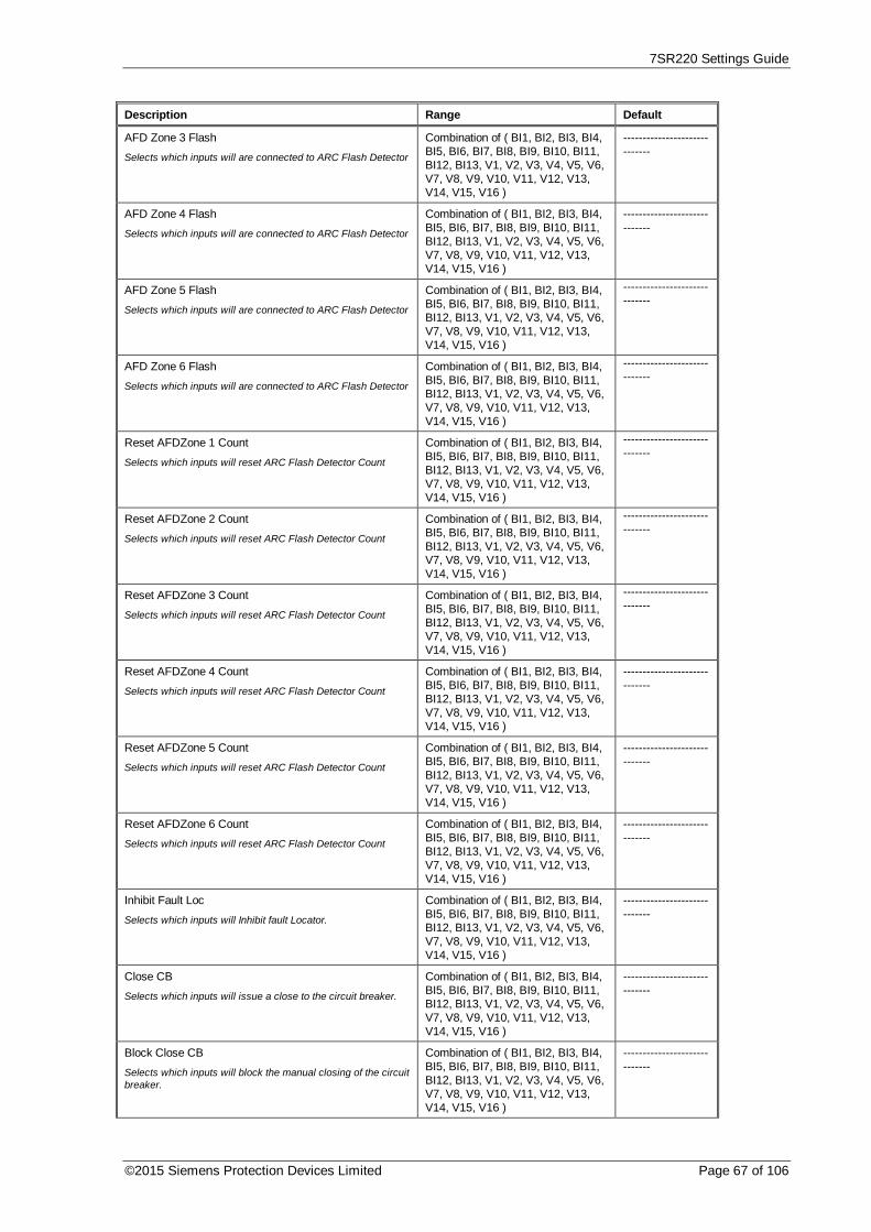
7SR220 Settings Guide
©2015 Siemens Protection Devices Limited Page 67 of 106
Description Range Default
AFD Zone 3 Flash
Selects which inputs will are connected to ARC Flash Detector
Combination of ( BI1, BI2, BI3, BI4,BI5, BI6, BI7, BI8, BI9, BI10, BI11,BI12, BI13, V1, V2, V3, V4, V5, V6,V7, V8, V9, V10, V11, V12, V13,V14, V15, V16 )
-----------------------------
AFD Zone 4 Flash
Selects which inputs will are connected to ARC Flash Detector
Combination of ( BI1, BI2, BI3, BI4,BI5, BI6, BI7, BI8, BI9, BI10, BI11,BI12, BI13, V1, V2, V3, V4, V5, V6,V7, V8, V9, V10, V11, V12, V13,V14, V15, V16 )
-----------------------------
AFD Zone 5 Flash
Selects which inputs will are connected to ARC Flash Detector
Combination of ( BI1, BI2, BI3, BI4,BI5, BI6, BI7, BI8, BI9, BI10, BI11,BI12, BI13, V1, V2, V3, V4, V5, V6,V7, V8, V9, V10, V11, V12, V13,V14, V15, V16 )
-----------------------------
AFD Zone 6 Flash
Selects which inputs will are connected to ARC Flash Detector
Combination of ( BI1, BI2, BI3, BI4,BI5, BI6, BI7, BI8, BI9, BI10, BI11,BI12, BI13, V1, V2, V3, V4, V5, V6,V7, V8, V9, V10, V11, V12, V13,V14, V15, V16 )
-----------------------------
Reset AFDZone 1 Count
Selects which inputs will reset ARC Flash Detector Count
Combination of ( BI1, BI2, BI3, BI4,BI5, BI6, BI7, BI8, BI9, BI10, BI11,BI12, BI13, V1, V2, V3, V4, V5, V6,V7, V8, V9, V10, V11, V12, V13,V14, V15, V16 )
-----------------------------
Reset AFDZone 2 Count
Selects which inputs will reset ARC Flash Detector Count
Combination of ( BI1, BI2, BI3, BI4,BI5, BI6, BI7, BI8, BI9, BI10, BI11,BI12, BI13, V1, V2, V3, V4, V5, V6,V7, V8, V9, V10, V11, V12, V13,V14, V15, V16 )
-----------------------------
Reset AFDZone 3 Count
Selects which inputs will reset ARC Flash Detector Count
Combination of ( BI1, BI2, BI3, BI4,BI5, BI6, BI7, BI8, BI9, BI10, BI11,BI12, BI13, V1, V2, V3, V4, V5, V6,V7, V8, V9, V10, V11, V12, V13,V14, V15, V16 )
-----------------------------
Reset AFDZone 4 Count
Selects which inputs will reset ARC Flash Detector Count
Combination of ( BI1, BI2, BI3, BI4,BI5, BI6, BI7, BI8, BI9, BI10, BI11,BI12, BI13, V1, V2, V3, V4, V5, V6,V7, V8, V9, V10, V11, V12, V13,V14, V15, V16 )
-----------------------------
Reset AFDZone 5 Count
Selects which inputs will reset ARC Flash Detector Count
Combination of ( BI1, BI2, BI3, BI4,BI5, BI6, BI7, BI8, BI9, BI10, BI11,BI12, BI13, V1, V2, V3, V4, V5, V6,V7, V8, V9, V10, V11, V12, V13,V14, V15, V16 )
-----------------------------
Reset AFDZone 6 Count
Selects which inputs will reset ARC Flash Detector Count
Combination of ( BI1, BI2, BI3, BI4,BI5, BI6, BI7, BI8, BI9, BI10, BI11,BI12, BI13, V1, V2, V3, V4, V5, V6,V7, V8, V9, V10, V11, V12, V13,V14, V15, V16 )
-----------------------------
Inhibit Fault Loc
Selects which inputs will Inhibit fault Locator.
Combination of ( BI1, BI2, BI3, BI4,BI5, BI6, BI7, BI8, BI9, BI10, BI11,BI12, BI13, V1, V2, V3, V4, V5, V6,V7, V8, V9, V10, V11, V12, V13,V14, V15, V16 )
-----------------------------
Close CB
Selects which inputs will issue a close to the circuit breaker.
Combination of ( BI1, BI2, BI3, BI4,BI5, BI6, BI7, BI8, BI9, BI10, BI11,BI12, BI13, V1, V2, V3, V4, V5, V6,V7, V8, V9, V10, V11, V12, V13,V14, V15, V16 )
-----------------------------
Block Close CB
Selects which inputs will block the manual closing of the circuitbreaker.
Combination of ( BI1, BI2, BI3, BI4,BI5, BI6, BI7, BI8, BI9, BI10, BI11,BI12, BI13, V1, V2, V3, V4, V5, V6,V7, V8, V9, V10, V11, V12, V13,V14, V15, V16 )
-----------------------------

7SR220 Settings Guide
Page 68 of 106 © 2013 Siemens Protection Devices Limited
Description Range Default
Open CB
Selects which inputs will issue an open to the circuit breaker.
Combination of ( BI1, BI2, BI3, BI4,BI5, BI6, BI7, BI8, BI9, BI10, BI11,BI12, BI13, V1, V2, V3, V4, V5, V6,V7, V8, V9, V10, V11, V12, V13,V14, V15, V16 )
-----------------------------
79 Out
Selects which inputs will switch the Auto-recloser out ofservice
Combination of ( BI1, BI2, BI3, BI4,BI5, BI6, BI7, BI8, BI9, BI10, BI11,BI12, BI13, V1, V2, V3, V4, V5, V6,V7, V8, V9, V10, V11, V12, V13,V14, V15, V16 )
-----------------------------
79 In
Selects which inputs will switch the Auto-recloser in service
Combination of ( BI1, BI2, BI3, BI4,BI5, BI6, BI7, BI8, BI9, BI10, BI11,BI12, BI13, V1, V2, V3, V4, V5, V6,V7, V8, V9, V10, V11, V12, V13,V14, V15, V16 )
-----------------------------
79 Trip & Reclose
Selects which inputs will trigger a trip & reclose
Combination of ( BI1, BI2, BI3, BI4,BI5, BI6, BI7, BI8, BI9, BI10, BI11,BI12, BI13, V1, V2, V3, V4, V5, V6,V7, V8, V9, V10, V11, V12, V13,V14, V15, V16 )
-----------------------------
79 Trip & Lockout
Selects which inputs will trigger a trip & lockout
Combination of ( BI1, BI2, BI3, BI4,BI5, BI6, BI7, BI8, BI9, BI10, BI11,BI12, BI13, V1, V2, V3, V4, V5, V6,V7, V8, V9, V10, V11, V12, V13,V14, V15, V16 )
-----------------------------
79 Ext Trip
Selects which input will start the external an Auto-relosesequence
Combination of ( BI1, BI2, BI3, BI4,BI5, BI6, BI7, BI8, BI9, BI10, BI11,BI12, BI13, V1, V2, V3, V4, V5, V6,V7, V8, V9, V10, V11, V12, V13,V14, V15, V16 )
-----------------------------
79 Ext Pickup
Selects which input should be connected to the pickup of theexternal elements required to start an Auto-reclose sequence
Combination of ( BI1, BI2, BI3, BI4,BI5, BI6, BI7, BI8, BI9, BI10, BI11,BI12, BI13, V1, V2, V3, V4, V5, V6,V7, V8, V9, V10, V11, V12, V13,V14, V15, V16 )
-----------------------------
79 Block Reclose
Selects which inputs will block the Auto-recloser
Combination of ( BI1, BI2, BI3, BI4,BI5, BI6, BI7, BI8, BI9, BI10, BI11,BI12, BI13, V1, V2, V3, V4, V5, V6,V7, V8, V9, V10, V11, V12, V13,V14, V15, V16 )
-----------------------------
79 Reset Lockout
Selects which inputs will force the Auto-recloser into theLockout state
Combination of ( BI1, BI2, BI3, BI4,BI5, BI6, BI7, BI8, BI9, BI10, BI11,BI12, BI13, V1, V2, V3, V4, V5, V6,V7, V8, V9, V10, V11, V12, V13,V14, V15, V16 )
-----------------------------
79 Line Check
Selects which inputs will start the Line Check functionality ofthe Auto-recloser
Combination of ( BI1, BI2, BI3, BI4,BI5, BI6, BI7, BI8, BI9, BI10, BI11,BI12, BI13, V1, V2, V3, V4, V5, V6,V7, V8, V9, V10, V11, V12, V13,V14, V15, V16 )
-----------------------------
79 Lockout
Selects which inputs will force the Auto-recloser into theLockout state
Combination of ( BI1, BI2, BI3, BI4,BI5, BI6, BI7, BI8, BI9, BI10, BI11,BI12, BI13, V1, V2, V3, V4, V5, V6,V7, V8, V9, V10, V11, V12, V13,V14, V15, V16 )
-----------------------------
79 Override Sync
Selects which inputs will start 79 Override Sync
Combination of ( BI1, BI2, BI3, BI4,BI5, BI6, BI7, BI8, BI9, BI10, BI11,BI12, BI13, V1, V2, V3, V4, V5, V6,V7, V8, V9, V10, V11, V12, V13,V14, V15, V16 )
-----------------------------
Man Override Sync
Selects which inputs will start Man Override Sync
Combination of ( BI1, BI2, BI3, BI4,BI5, BI6, BI7, BI8, BI9, BI10, BI11,BI12, BI13, V1, V2, V3, V4, V5, V6,V7, V8, V9, V10, V11, V12, V13,V14, V15, V16 )
-----------------------------
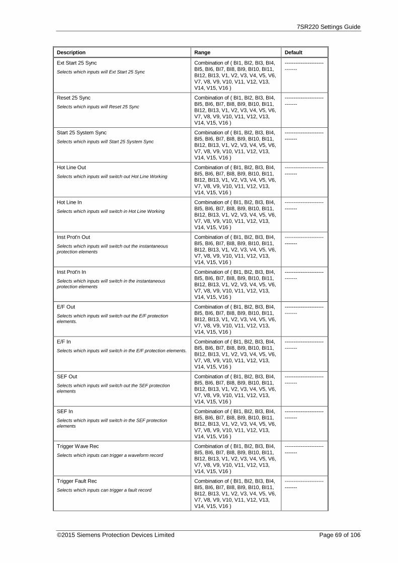
7SR220 Settings Guide
©2015 Siemens Protection Devices Limited Page 69 of 106
Description Range Default
Ext Start 25 Sync
Selects which inputs will Ext Start 25 Sync
Combination of ( BI1, BI2, BI3, BI4,BI5, BI6, BI7, BI8, BI9, BI10, BI11,BI12, BI13, V1, V2, V3, V4, V5, V6,V7, V8, V9, V10, V11, V12, V13,V14, V15, V16 )
-----------------------------
Reset 25 Sync
Selects which inputs will Reset 25 Sync
Combination of ( BI1, BI2, BI3, BI4,BI5, BI6, BI7, BI8, BI9, BI10, BI11,BI12, BI13, V1, V2, V3, V4, V5, V6,V7, V8, V9, V10, V11, V12, V13,V14, V15, V16 )
-----------------------------
Start 25 System Sync
Selects which inputs will Start 25 System Sync
Combination of ( BI1, BI2, BI3, BI4,BI5, BI6, BI7, BI8, BI9, BI10, BI11,BI12, BI13, V1, V2, V3, V4, V5, V6,V7, V8, V9, V10, V11, V12, V13,V14, V15, V16 )
-----------------------------
Hot Line Out
Selects which inputs will switch out Hot Line Working
Combination of ( BI1, BI2, BI3, BI4,BI5, BI6, BI7, BI8, BI9, BI10, BI11,BI12, BI13, V1, V2, V3, V4, V5, V6,V7, V8, V9, V10, V11, V12, V13,V14, V15, V16 )
-----------------------------
Hot Line In
Selects which inputs will switch in Hot Line Working
Combination of ( BI1, BI2, BI3, BI4,BI5, BI6, BI7, BI8, BI9, BI10, BI11,BI12, BI13, V1, V2, V3, V4, V5, V6,V7, V8, V9, V10, V11, V12, V13,V14, V15, V16 )
-----------------------------
Inst Prot'n Out
Selects which inputs will switch out the instantaneousprotection elements
Combination of ( BI1, BI2, BI3, BI4,BI5, BI6, BI7, BI8, BI9, BI10, BI11,BI12, BI13, V1, V2, V3, V4, V5, V6,V7, V8, V9, V10, V11, V12, V13,V14, V15, V16 )
-----------------------------
Inst Prot'n In
Selects which inputs will switch in the instantaneousprotection elements
Combination of ( BI1, BI2, BI3, BI4,BI5, BI6, BI7, BI8, BI9, BI10, BI11,BI12, BI13, V1, V2, V3, V4, V5, V6,V7, V8, V9, V10, V11, V12, V13,V14, V15, V16 )
-----------------------------
E/F Out
Selects which inputs will switch out the E/F protectionelements.
Combination of ( BI1, BI2, BI3, BI4,BI5, BI6, BI7, BI8, BI9, BI10, BI11,BI12, BI13, V1, V2, V3, V4, V5, V6,V7, V8, V9, V10, V11, V12, V13,V14, V15, V16 )
-----------------------------
E/F In
Selects which inputs will switch in the E/F protection elements.
Combination of ( BI1, BI2, BI3, BI4,BI5, BI6, BI7, BI8, BI9, BI10, BI11,BI12, BI13, V1, V2, V3, V4, V5, V6,V7, V8, V9, V10, V11, V12, V13,V14, V15, V16 )
-----------------------------
SEF Out
Selects which inputs will switch out the SEF protectionelements
Combination of ( BI1, BI2, BI3, BI4,BI5, BI6, BI7, BI8, BI9, BI10, BI11,BI12, BI13, V1, V2, V3, V4, V5, V6,V7, V8, V9, V10, V11, V12, V13,V14, V15, V16 )
-----------------------------
SEF In
Selects which inputs will switch in the SEF protectionelements
Combination of ( BI1, BI2, BI3, BI4,BI5, BI6, BI7, BI8, BI9, BI10, BI11,BI12, BI13, V1, V2, V3, V4, V5, V6,V7, V8, V9, V10, V11, V12, V13,V14, V15, V16 )
-----------------------------
Trigger Wave Rec
Selects which inputs can trigger a waveform record
Combination of ( BI1, BI2, BI3, BI4,BI5, BI6, BI7, BI8, BI9, BI10, BI11,BI12, BI13, V1, V2, V3, V4, V5, V6,V7, V8, V9, V10, V11, V12, V13,V14, V15, V16 )
-----------------------------
Trigger Fault Rec
Selects which inputs can trigger a fault record
Combination of ( BI1, BI2, BI3, BI4,BI5, BI6, BI7, BI8, BI9, BI10, BI11,BI12, BI13, V1, V2, V3, V4, V5, V6,V7, V8, V9, V10, V11, V12, V13,V14, V15, V16 )
-----------------------------

7SR220 Settings Guide
Page 70 of 106 © 2013 Siemens Protection Devices Limited
Description Range Default
Select Group 1
Switches active setting group to group 1
Combination of ( BI1, BI2, BI3, BI4,BI5, BI6, BI7, BI8, BI9, BI10, BI11,BI12, BI13, V1, V2, V3, V4, V5, V6,V7, V8, V9, V10, V11, V12, V13,V14, V15, V16 )
-----------------------------
Reset Energy Meters Combination of ( BI1, BI2, BI3, BI4,BI5, BI6, BI7, BI8, BI9, BI10, BI11,BI12, BI13, V1, V2, V3, V4, V5, V6,V7, V8, V9, V10, V11, V12, V13,V14, V15, V16 )
-----------------------------
Select Group 2
Switches active setting group to group 2
Combination of ( BI1, BI2, BI3, BI4,BI5, BI6, BI7, BI8, BI9, BI10, BI11,BI12, BI13, V1, V2, V3, V4, V5, V6,V7, V8, V9, V10, V11, V12, V13,V14, V15, V16 )
-----------------------------
Select Group 3
Switches active setting group to group 3
Combination of ( BI1, BI2, BI3, BI4,BI5, BI6, BI7, BI8, BI9, BI10, BI11,BI12, BI13, V1, V2, V3, V4, V5, V6,V7, V8, V9, V10, V11, V12, V13,V14, V15, V16 )
-----------------------------
Select Group 4
Switches active setting group to group 4
Combination of ( BI1, BI2, BI3, BI4,BI5, BI6, BI7, BI8, BI9, BI10, BI11,BI12, BI13, V1, V2, V3, V4, V5, V6,V7, V8, V9, V10, V11, V12, V13,V14, V15, V16 )
-----------------------------
Select Group 5
Switches active setting group to group 5
Combination of ( BI1, BI2, BI3, BI4,BI5, BI6, BI7, BI8, BI9, BI10, BI11,BI12, BI13, V1, V2, V3, V4, V5, V6,V7, V8, V9, V10, V11, V12, V13,V14, V15, V16 )
-----------------------------
Select Group 6
Switches active setting group to group 6
Combination of ( BI1, BI2, BI3, BI4,BI5, BI6, BI7, BI8, BI9, BI10, BI11,BI12, BI13, V1, V2, V3, V4, V5, V6,V7, V8, V9, V10, V11, V12, V13,V14, V15, V16 )
-----------------------------
Select Group 7
Switches active setting group to group 7
Combination of ( BI1, BI2, BI3, BI4,BI5, BI6, BI7, BI8, BI9, BI10, BI11,BI12, BI13, V1, V2, V3, V4, V5, V6,V7, V8, V9, V10, V11, V12, V13,V14, V15, V16 )
-----------------------------
Select Group 8
Switches active setting group to group 8
Combination of ( BI1, BI2, BI3, BI4,BI5, BI6, BI7, BI8, BI9, BI10, BI11,BI12, BI13, V1, V2, V3, V4, V5, V6,V7, V8, V9, V10, V11, V12, V13,V14, V15, V16 )
-----------------------------
Out Of Service Mode
Selects which inputs will put the relay into Out Of ServiceMode
Combination of ( BI1, BI2, BI3, BI4,BI5, BI6, BI7, BI8, BI9, BI10, BI11,BI12, BI13, V1, V2, V3, V4, V5, V6,V7, V8, V9, V10, V11, V12, V13,V14, V15, V16 )
-----------------------------
Local Mode
Selects which inputs will put the relay into Local Mode
Combination of ( BI1, BI2, BI3, BI4,BI5, BI6, BI7, BI8, BI9, BI10, BI11,BI12, BI13, V1, V2, V3, V4, V5, V6,V7, V8, V9, V10, V11, V12, V13,V14, V15, V16 )
-----------------------------
Remote Mode
Selects which inputs will put the relay into Remote Mode
Combination of ( BI1, BI2, BI3, BI4,BI5, BI6, BI7, BI8, BI9, BI10, BI11,BI12, BI13, V1, V2, V3, V4, V5, V6,V7, V8, V9, V10, V11, V12, V13,V14, V15, V16 )
-----------------------------
Local Or Remote Mode
Selects which inputs will put the relay into Local Or RemoteMode
Combination of ( BI1, BI2, BI3, BI4,BI5, BI6, BI7, BI8, BI9, BI10, BI11,BI12, BI13, V1, V2, V3, V4, V5, V6,V7, V8, V9, V10, V11, V12, V13,V14, V15, V16 )
-----------------------------

7SR220 Settings Guide
©2015 Siemens Protection Devices Limited Page 71 of 106
Description Range Default
Clock Sync.
Selects which input is used to synchronise the real time clock
Combination of ( BI1, BI2, BI3, BI4,BI5, BI6, BI7, BI8, BI9, BI10, BI11,BI12, BI13, V1, V2, V3, V4, V5, V6,V7, V8, V9, V10, V11, V12, V13,V14, V15, V16 )
-----------------------------
Reset LEDs & O/Ps
Selects which inputs will reset the latched LEDs and binaryoutputs
Combination of ( BI1, BI2, BI3, BI4,BI5, BI6, BI7, BI8, BI9, BI10, BI11,BI12, BI13, V1, V2, V3, V4, V5, V6,V7, V8, V9, V10, V11, V12, V13,V14, V15, V16 )
-----------------------------
Inverted Inputs
Selects which inputs will be inverted
Combination of ( BI1, BI2, BI3, BI4,BI5, BI6, BI7, BI8, BI9, BI10, BI11,BI12, BI13)
-----------------------------
Enable In Local
Selects which inputs will be enabled in local mode
Combination of ( BI1, BI2, BI3, BI4,BI5, BI6, BI7, BI8, BI9, BI10, BI11,BI12, BI13)
BI1, BI2, BI3,BI4, BI5, BI6,BI7, BI8, BI9,BI10, BI11, BI12,BI13
Enable In Remote
Selects which inputs will be enabled in remote mode
Combination of ( BI1, BI2, BI3, BI4,BI5, BI6, BI7, BI8, BI9, BI10, BI11,BI12, BI13)
BI1, BI2, BI3,BI4, BI5, BI6,BI7, BI8, BI9,BI10, BI11, BI12,BI13
3.12.2. Function Key Matrix
Description Range Default
Open CB
Selects which function key will Open the circuit breaker
Combination of ( 1, 2, 3, 4, 5, 6 ) ------
Close CB
Selects which function key will Close the circuit breaker
Combination of ( 1, 2, 3, 4, 5, 6 ) ------
79 In/Out
Selects which function key will toggle Autoreclose In & Out
Combination of ( 1, 2, 3, 4, 5, 6 ) ------
79 Trip & Reclose
Selects which function key will cause the CB to trip & reclose
Combination of ( 1, 2, 3, 4, 5, 6 ) ------
79 Trip & Lockout
Selects which function key will cause the CB to trip & lockout
Combination of ( 1, 2, 3, 4, 5, 6 ) ------
Hot Line Work In/Out
Selects which function key will toggle Hot Line Working In &Out
Combination of ( 1, 2, 3, 4, 5, 6 ) ------
E/F In/Out
Selects which function key will toggle E/F protection In & Out
Combination of ( 1, 2, 3, 4, 5, 6 ) ------
SEF In/Out
Selects which function key will toggle SEF protection In & Out
Combination of ( 1, 2, 3, 4, 5, 6 ) ------
Inst Prot'n In/Out
Selects which function key will toggle Instantaneous protectionelements In & Out
Combination of ( 1, 2, 3, 4, 5, 6 ) ------
Out Of Service Mode Combination of ( 1, 2, 3, 4, 5, 6 ) ------
Local Mode Combination of ( 1, 2, 3, 4, 5, 6 ) ------
Remote Mode Combination of ( 1, 2, 3, 4, 5, 6 ) ------
Local Or Remote Mode
Selects which inputs will put the relay into Local Or RemoteMode
Combination of ( 1, 2, 3, 4, 5, 6 ) ------

7SR220 Settings Guide
Page 72 of 106 © 2013 Siemens Protection Devices Limited

7SR220 Settings Guide
©2015 Siemens Protection Devices Limited Page 73 of 106
3.12.3. Binary Input Config
Description Range Default
Inverted Inputs
Selects which inputs pickup when voltage is removed.
Combination of ( 1, 2, 3, 4, 5, 6, 7,8, 9, 10, 11, 12, 13 )
-------------
BI 1 Pick-up Delay
Delay on pickup of DC Binary Input 1
0, 0.005 ... 14300, 14400 0.02 s
BI 1 Drop-off Delay
Delay on dropoff of DC Binary Input 1
0, 0.005 ... 14300, 14400 0 s
BI 2 Pick-up Delay
Delay on pickup of DC Binary Input 2
0, 0.005 ... 14300, 14400 0.02 s
BI 2 Drop-off Delay
Delay on dropoff of DC Binary Input 2
0, 0.005 ... 14300, 14400 0 s
BI 3 Pick-up Delay
Delay on pickup of DC Binary Input 3
0, 0.005 ... 14300, 14400 0.02 s
BI 3 Drop-off Delay
Delay on dropoff of DC Binary Input 3
0, 0.005 ... 14300, 14400 0 s
BI 4 Pick-up Delay
Delay on pickup of DC Binary Input 4
0, 0.005 ... 14300, 14400 0.02 s
BI 4 Drop-off Delay
Delay on dropoff of DC Binary Input 4
0, 0.005 ... 14300, 14400 0 s
BI 5 Pick-up Delay
Delay on pickup of DC Binary Input 5
0, 0.005 ... 14300, 14400 0.02 s
BI 5 Drop-off Delay
Delay on dropoff of DC Binary Input 5
0, 0.005 ... 14300, 14400 0 s
BI 6 Pick-up Delay
Delay on pickup of DC Binary Input 6
0, 0.005 ... 14300, 14400 0.02 s
BI 6 Drop-off Delay
Delay on dropoff of DC Binary Input 6
0, 0.005 ... 14300, 14400 0 s
BI 7 Pick-up Delay
Delay on pickup of DC Binary Input 7
0, 0.005 ... 14300, 14400 0.02 s
BI 7 Drop-off Delay
Delay on dropoff of DC Binary Input 7
0, 0.005 ... 14300, 14400 0 s
BI 8 Pick-up Delay
Delay on pickup of DC Binary Input 8
0, 0.005 ... 14300, 14400 0.02 s
BI 8 Drop-off Delay
Delay on dropoff of DC Binary Input 8
0, 0.005 ... 14300, 14400 0 s
BI 9 Pick-up Delay
Delay on pickup of DC Binary Input 9
0, 0.005 ... 14300, 14400 0.02 s
BI 9 Drop-off Delay
Delay on dropoff of DC Binary Input 9
0, 0.005 ... 14300, 14400 0 s
BI 10 Pick-up Delay
Delay on pickup of DC Binary Input 10
0, 0.005 ... 14300, 14400 0.02 s
BI 10 Drop-off Delay
Delay on dropoff of DC Binary Input 10
0, 0.005 ... 14300, 14400 0 s
BI 11 Pick-up Delay
Delay on pickup of DC Binary Input 11
0, 0.005 ... 14300, 14400 0.02 s
BI 11 Drop-off Delay
Delay on dropoff of DC Binary Input 11
0, 0.005 ... 14300, 14400 0 s

7SR220 Settings Guide
Page 74 of 106 © 2013 Siemens Protection Devices Limited
Description Range Default
BI 12 Pick-up Delay
Delay on pickup of DC Binary Input 12
0, 0.005 ... 14300, 14400 0.02 s
BI 12 Drop-off Delay
Delay on dropoff of DC Binary Input 12
0, 0.005 ... 14300, 14400 0 s
BI 13 Pick-up Delay
Delay on pickup of DC Binary Input 13
0, 0.005 ... 14300, 14400 0.02 s
BI 13 Drop-off Delay
Delay on dropoff of DC Binary Input 13
0, 0.005 ... 14300, 14400 0 s
Enabled In Local
Selects which inputs are enabled when the relay is inOperating Mode 'Local' or 'Local Or Remote'
Combination of ( 1, 2, 3, 4, 5, 6, 7,8, 9, 10, 11, 12, 13 )
1, 2, 3, 4, 5, 6, 7,8, 9, 10, 11, 12,13
Enabled In Remote
Selects which inputs are enabled when the relay is inOperating Mode 'Remote' or 'Local Or Remote'
Combination of ( 1, 2, 3, 4, 5, 6, 7,8, 9, 10, 11, 12, 13 )
1, 2, 3, 4, 5, 6, 7,8, 9, 10, 11, 12,13
3.12.4. Function Key Config
Description Range Default
Function Key 1 Text
User definable text that will be used in the HMI function keyconfirmation screen when Function key 1 is pressed.
(20 Character String) Function Key 1
Function Key 2 Text
User definable text that will be used in the HMI function keyconfirmation screen when Function key 2 is pressed.
(20 Character String) Function Key 2
Function Key 3 Text
User definable text that will be used in the HMI function keyconfirmation screen when Function key 3 is pressed.
(20 Character String) Function Key 3
Function Key 4 Text
User definable text that will be used in the HMI function keyconfirmation screen when Function key 4 is pressed.
(20 Character String) Function Key 4
Function Key 5 Text
User definable text that will be used in the HMI function keyconfirmation screen when Function key 5 is pressed.
(20 Character String) Function Key 5
Function Key 6 Text
User definable text that will be used in the HMI function keyconfirmation screen when Function key 6 is pressed.
(20 Character String) Function Key 6
Enabled In Remote
Selects which inputs are enabled when the relay is inOperating Mode 'Remote' or 'Local Or Remote'
Combination of ( 1, 2, 3, 4, 5, 6 ) ------

7SR220 Settings Guide
©2015 Siemens Protection Devices Limited Page 75 of 106
3.12.5. General Alarms
Description Range Default
General Alarm-1
Defines the text to be displayed for General Alarm 1
(16 Character String) ALARM 1
General Alarm-2
Defines the text to be displayed for General Alarm 2
(16 Character String) ALARM 2
General Alarm-3
Defines the text to be displayed for General Alarm 3
(16 Character String) ALARM 3
General Alarm-4
Defines the text to be displayed for General Alarm 4
(16 Character String) ALARM 4
General Alarm-5
Defines the text to be displayed for General Alarm 5
(16 Character String) ALARM 5
General Alarm-6
Defines the text to be displayed for General Alarm 6
(16 Character String) ALARM 6
General Alarm-7
Defines the text to be displayed for General Alarm 7
(16 Character String) ALARM 7
General Alarm-8
Defines the text to be displayed for General Alarm 8
(16 Character String) ALARM 8
General Alarm-9
Defines the text to be displayed for General Alarm 9
(16 Character String) ALARM 9
General Alarm-10
Defines the text to be displayed for General Alarm 10
(16 Character String) ALARM 10
General Alarm-11
Defines the text to be displayed for General Alarm 11
(16 Character String) ALARM 11
General Alarm-12
Defines the text to be displayed for General Alarm 12
(16 Character String) ALARM 12
General Alarm-13
Defines the text to be displayed for General Alarm 13
(16 Character String) ALARM 13
General Alarm-14
Defines the text to be displayed for General Alarm 14
(16 Character String) ALARM 14
General Alarm-15
Defines the text to be displayed for General Alarm 15
(16 Character String) ALARM 15
General Alarm-16
Defines the text to be displayed for General Alarm 16
(16 Character String) ALARM 16
General Alarm-17
Defines the text to be displayed for General Alarm 17
(16 Character String) ALARM 17
General Alarm-18
Defines the text to be displayed for General Alarm 18
(16 Character String) ALARM 18
General Alarm-19
Defines the text to be displayed for General Alarm 19
(16 Character String) ALARM 19
General Alarm-20
Defines the text to be displayed for General Alarm 20
(16 Character String) ALARM 20

7SR220 Settings Guide
Page 76 of 106 © 2013 Siemens Protection Devices Limited
3.13. Output Config
3.13.1. Output Matrix
Description Range Default
Protection Healthy
Relays selected are energised whilst relay self-monitoringdoes NOT detect any hardware or software errors and DCSupply is healthy. A changeover contact or normally closedcontact may be used to generate Protection Defective from thisoutput
Combination of ( BO1, BO2, BO3,BO4, BO5, BO6, BO7, BO8, BO9,BO10, BO11, BO12, BO13, BO14,L1, L2, L3, L4, L5, L6, L7, L8, L9,L10, L11, L12, L13, L14, V1, V2,V3, V4, V5, V6, V7, V8, V9, V10,V11, V12, V13, V14, V15, V16 )
BO1
Active Setting Grp 1 Combination of ( BO1, BO2, BO3,BO4, BO5, BO6, BO7, BO8, BO9,BO10, BO11, BO12, BO13, BO14,L1, L2, L3, L4, L5, L6, L7, L8, L9,L10, L11, L12, L13, L14, V1, V2,V3, V4, V5, V6, V7, V8, V9, V10,V11, V12, V13, V14, V15, V16 )
Grp 1
Active Setting Grp 2 Combination of ( BO1, BO2, BO3,BO4, BO5, BO6, BO7, BO8, BO9,BO10, BO11, BO12, BO13, BO14,L1, L2, L3, L4, L5, L6, L7, L8, L9,L10, L11, L12, L13, L14, V1, V2,V3, V4, V5, V6, V7, V8, V9, V10,V11, V12, V13, V14, V15, V16 )
Active Setting Grp 3 Combination of ( BO1, BO2, BO3,BO4, BO5, BO6, BO7, BO8, BO9,BO10, BO11, BO12, BO13, BO14,L1, L2, L3, L4, L5, L6, L7, L8, L9,L10, L11, L12, L13, L14, V1, V2,V3, V4, V5, V6, V7, V8, V9, V10,V11, V12, V13, V14, V15, V16 )
Active Setting Grp 4 Combination of ( BO1, BO2, BO3,BO4, BO5, BO6, BO7, BO8, BO9,BO10, BO11, BO12, BO13, BO14,L1, L2, L3, L4, L5, L6, L7, L8, L9,L10, L11, L12, L13, L14, V1, V2,V3, V4, V5, V6, V7, V8, V9, V10,V11, V12, V13, V14, V15, V16 )
Active Setting Grp 5 Combination of ( BO1, BO2, BO3,BO4, BO5, BO6, BO7, BO8, BO9,BO10, BO11, BO12, BO13, BO14,L1, L2, L3, L4, L5, L6, L7, L8, L9,L10, L11, L12, L13, L14, V1, V2,V3, V4, V5, V6, V7, V8, V9, V10,V11, V12, V13, V14, V15, V16 )
Active Setting Grp 6 Combination of ( BO1, BO2, BO3,BO4, BO5, BO6, BO7, BO8, BO9,BO10, BO11, BO12, BO13, BO14,L1, L2, L3, L4, L5, L6, L7, L8, L9,L10, L11, L12, L13, L14, V1, V2,V3, V4, V5, V6, V7, V8, V9, V10,V11, V12, V13, V14, V15, V16 )
Active Setting Grp 7 Combination of ( BO1, BO2, BO3,BO4, BO5, BO6, BO7, BO8, BO9,BO10, BO11, BO12, BO13, BO14,L1, L2, L3, L4, L5, L6, L7, L8, L9,L10, L11, L12, L13, L14, V1, V2,V3, V4, V5, V6, V7, V8, V9, V10,V11, V12, V13, V14, V15, V16 )
Active Setting Grp 8 Combination of ( BO1, BO2, BO3,BO4, BO5, BO6, BO7, BO8, BO9,BO10, BO11, BO12, BO13, BO14,L1, L2, L3, L4, L5, L6, L7, L8, L9,L10, L11, L12, L13, L14, V1, V2,V3, V4, V5, V6, V7, V8, V9, V10,V11, V12, V13, V14, V15, V16 )
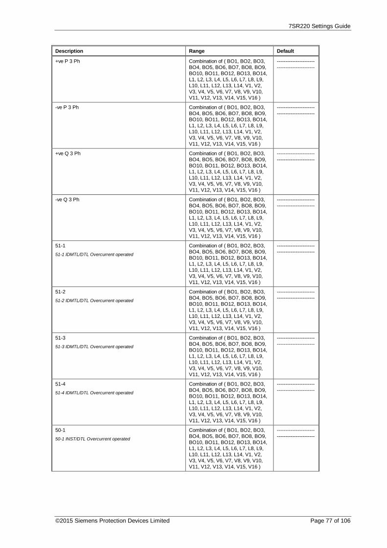
7SR220 Settings Guide
©2015 Siemens Protection Devices Limited Page 77 of 106
Description Range Default
+ve P 3 Ph Combination of ( BO1, BO2, BO3,BO4, BO5, BO6, BO7, BO8, BO9,BO10, BO11, BO12, BO13, BO14,L1, L2, L3, L4, L5, L6, L7, L8, L9,L10, L11, L12, L13, L14, V1, V2,V3, V4, V5, V6, V7, V8, V9, V10,V11, V12, V13, V14, V15, V16 )
--------------------------------------------
-ve P 3 Ph Combination of ( BO1, BO2, BO3,BO4, BO5, BO6, BO7, BO8, BO9,BO10, BO11, BO12, BO13, BO14,L1, L2, L3, L4, L5, L6, L7, L8, L9,L10, L11, L12, L13, L14, V1, V2,V3, V4, V5, V6, V7, V8, V9, V10,V11, V12, V13, V14, V15, V16 )
--------------------------------------------
+ve Q 3 Ph Combination of ( BO1, BO2, BO3,BO4, BO5, BO6, BO7, BO8, BO9,BO10, BO11, BO12, BO13, BO14,L1, L2, L3, L4, L5, L6, L7, L8, L9,L10, L11, L12, L13, L14, V1, V2,V3, V4, V5, V6, V7, V8, V9, V10,V11, V12, V13, V14, V15, V16 )
--------------------------------------------
-ve Q 3 Ph Combination of ( BO1, BO2, BO3,BO4, BO5, BO6, BO7, BO8, BO9,BO10, BO11, BO12, BO13, BO14,L1, L2, L3, L4, L5, L6, L7, L8, L9,L10, L11, L12, L13, L14, V1, V2,V3, V4, V5, V6, V7, V8, V9, V10,V11, V12, V13, V14, V15, V16 )
--------------------------------------------
51-1
51-1 IDMTL/DTL Overcurrent operated
Combination of ( BO1, BO2, BO3,BO4, BO5, BO6, BO7, BO8, BO9,BO10, BO11, BO12, BO13, BO14,L1, L2, L3, L4, L5, L6, L7, L8, L9,L10, L11, L12, L13, L14, V1, V2,V3, V4, V5, V6, V7, V8, V9, V10,V11, V12, V13, V14, V15, V16 )
--------------------------------------------
51-2
51-2 IDMTL/DTL Overcurrent operated
Combination of ( BO1, BO2, BO3,BO4, BO5, BO6, BO7, BO8, BO9,BO10, BO11, BO12, BO13, BO14,L1, L2, L3, L4, L5, L6, L7, L8, L9,L10, L11, L12, L13, L14, V1, V2,V3, V4, V5, V6, V7, V8, V9, V10,V11, V12, V13, V14, V15, V16 )
--------------------------------------------
51-3
51-3 IDMTL/DTL Overcurrent operated
Combination of ( BO1, BO2, BO3,BO4, BO5, BO6, BO7, BO8, BO9,BO10, BO11, BO12, BO13, BO14,L1, L2, L3, L4, L5, L6, L7, L8, L9,L10, L11, L12, L13, L14, V1, V2,V3, V4, V5, V6, V7, V8, V9, V10,V11, V12, V13, V14, V15, V16 )
--------------------------------------------
51-4
51-4 IDMTL/DTL Overcurrent operated
Combination of ( BO1, BO2, BO3,BO4, BO5, BO6, BO7, BO8, BO9,BO10, BO11, BO12, BO13, BO14,L1, L2, L3, L4, L5, L6, L7, L8, L9,L10, L11, L12, L13, L14, V1, V2,V3, V4, V5, V6, V7, V8, V9, V10,V11, V12, V13, V14, V15, V16 )
--------------------------------------------
50-1
50-1 INST/DTL Overcurrent operated
Combination of ( BO1, BO2, BO3,BO4, BO5, BO6, BO7, BO8, BO9,BO10, BO11, BO12, BO13, BO14,L1, L2, L3, L4, L5, L6, L7, L8, L9,L10, L11, L12, L13, L14, V1, V2,V3, V4, V5, V6, V7, V8, V9, V10,V11, V12, V13, V14, V15, V16 )
--------------------------------------------
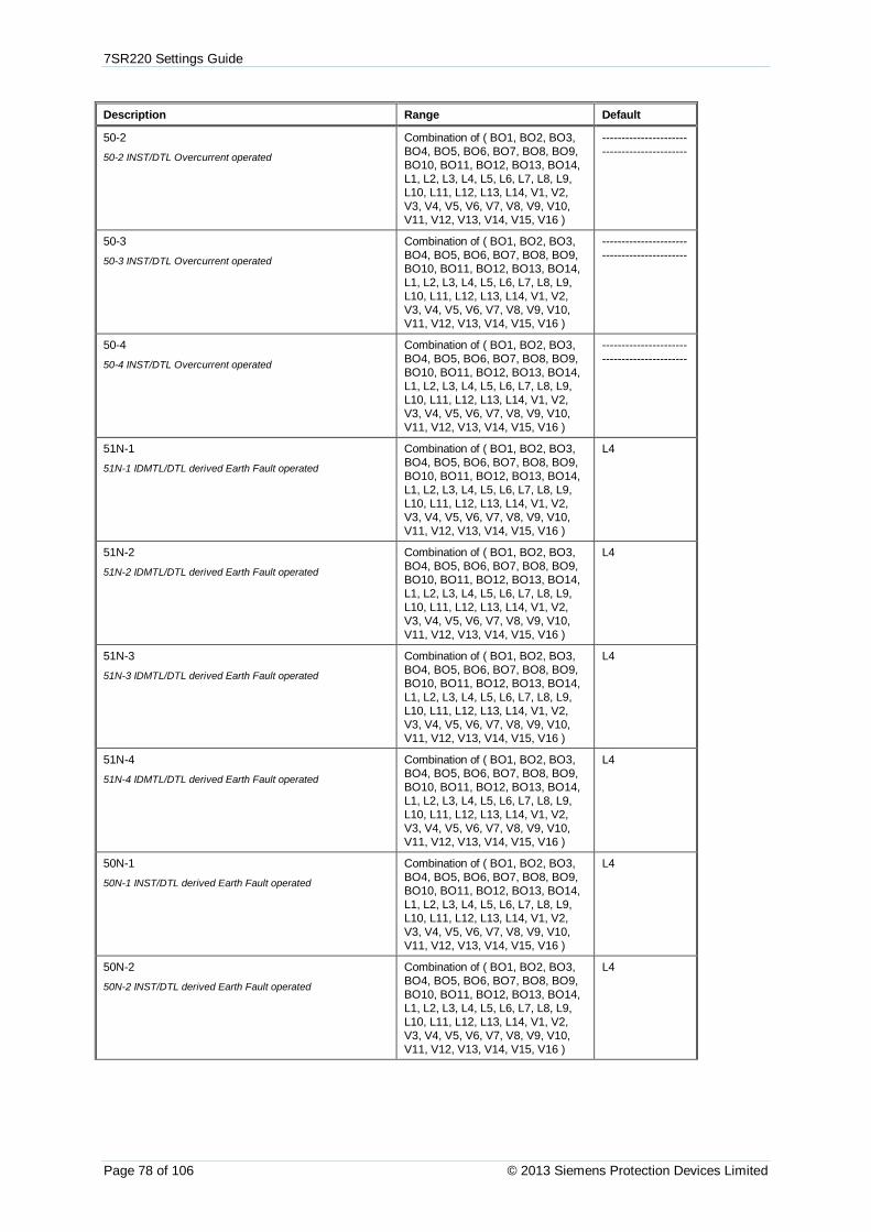
7SR220 Settings Guide
Page 78 of 106 © 2013 Siemens Protection Devices Limited
Description Range Default
50-2
50-2 INST/DTL Overcurrent operated
Combination of ( BO1, BO2, BO3,BO4, BO5, BO6, BO7, BO8, BO9,BO10, BO11, BO12, BO13, BO14,L1, L2, L3, L4, L5, L6, L7, L8, L9,L10, L11, L12, L13, L14, V1, V2,V3, V4, V5, V6, V7, V8, V9, V10,V11, V12, V13, V14, V15, V16 )
--------------------------------------------
50-3
50-3 INST/DTL Overcurrent operated
Combination of ( BO1, BO2, BO3,BO4, BO5, BO6, BO7, BO8, BO9,BO10, BO11, BO12, BO13, BO14,L1, L2, L3, L4, L5, L6, L7, L8, L9,L10, L11, L12, L13, L14, V1, V2,V3, V4, V5, V6, V7, V8, V9, V10,V11, V12, V13, V14, V15, V16 )
--------------------------------------------
50-4
50-4 INST/DTL Overcurrent operated
Combination of ( BO1, BO2, BO3,BO4, BO5, BO6, BO7, BO8, BO9,BO10, BO11, BO12, BO13, BO14,L1, L2, L3, L4, L5, L6, L7, L8, L9,L10, L11, L12, L13, L14, V1, V2,V3, V4, V5, V6, V7, V8, V9, V10,V11, V12, V13, V14, V15, V16 )
--------------------------------------------
51N-1
51N-1 IDMTL/DTL derived Earth Fault operated
Combination of ( BO1, BO2, BO3,BO4, BO5, BO6, BO7, BO8, BO9,BO10, BO11, BO12, BO13, BO14,L1, L2, L3, L4, L5, L6, L7, L8, L9,L10, L11, L12, L13, L14, V1, V2,V3, V4, V5, V6, V7, V8, V9, V10,V11, V12, V13, V14, V15, V16 )
L4
51N-2
51N-2 IDMTL/DTL derived Earth Fault operated
Combination of ( BO1, BO2, BO3,BO4, BO5, BO6, BO7, BO8, BO9,BO10, BO11, BO12, BO13, BO14,L1, L2, L3, L4, L5, L6, L7, L8, L9,L10, L11, L12, L13, L14, V1, V2,V3, V4, V5, V6, V7, V8, V9, V10,V11, V12, V13, V14, V15, V16 )
L4
51N-3
51N-3 IDMTL/DTL derived Earth Fault operated
Combination of ( BO1, BO2, BO3,BO4, BO5, BO6, BO7, BO8, BO9,BO10, BO11, BO12, BO13, BO14,L1, L2, L3, L4, L5, L6, L7, L8, L9,L10, L11, L12, L13, L14, V1, V2,V3, V4, V5, V6, V7, V8, V9, V10,V11, V12, V13, V14, V15, V16 )
L4
51N-4
51N-4 IDMTL/DTL derived Earth Fault operated
Combination of ( BO1, BO2, BO3,BO4, BO5, BO6, BO7, BO8, BO9,BO10, BO11, BO12, BO13, BO14,L1, L2, L3, L4, L5, L6, L7, L8, L9,L10, L11, L12, L13, L14, V1, V2,V3, V4, V5, V6, V7, V8, V9, V10,V11, V12, V13, V14, V15, V16 )
L4
50N-1
50N-1 INST/DTL derived Earth Fault operated
Combination of ( BO1, BO2, BO3,BO4, BO5, BO6, BO7, BO8, BO9,BO10, BO11, BO12, BO13, BO14,L1, L2, L3, L4, L5, L6, L7, L8, L9,L10, L11, L12, L13, L14, V1, V2,V3, V4, V5, V6, V7, V8, V9, V10,V11, V12, V13, V14, V15, V16 )
L4
50N-2
50N-2 INST/DTL derived Earth Fault operated
Combination of ( BO1, BO2, BO3,BO4, BO5, BO6, BO7, BO8, BO9,BO10, BO11, BO12, BO13, BO14,L1, L2, L3, L4, L5, L6, L7, L8, L9,L10, L11, L12, L13, L14, V1, V2,V3, V4, V5, V6, V7, V8, V9, V10,V11, V12, V13, V14, V15, V16 )
L4

7SR220 Settings Guide
©2015 Siemens Protection Devices Limited Page 79 of 106
Description Range Default
50N-3
50N-3 INST/DTL derived Earth Fault operated
Combination of ( BO1, BO2, BO3,BO4, BO5, BO6, BO7, BO8, BO9,BO10, BO11, BO12, BO13, BO14,L1, L2, L3, L4, L5, L6, L7, L8, L9,L10, L11, L12, L13, L14, V1, V2,V3, V4, V5, V6, V7, V8, V9, V10,V11, V12, V13, V14, V15, V16 )
L4
50N-4
50N-4 INST/DTL derived Earth Fault operated
Combination of ( BO1, BO2, BO3,BO4, BO5, BO6, BO7, BO8, BO9,BO10, BO11, BO12, BO13, BO14,L1, L2, L3, L4, L5, L6, L7, L8, L9,L10, L11, L12, L13, L14, V1, V2,V3, V4, V5, V6, V7, V8, V9, V10,V11, V12, V13, V14, V15, V16 )
L4
51G-1
51G-1 IDMTL/DTL measured Earth Fault operated
Combination of ( BO1, BO2, BO3,BO4, BO5, BO6, BO7, BO8, BO9,BO10, BO11, BO12, BO13, BO14,L1, L2, L3, L4, L5, L6, L7, L8, L9,L10, L11, L12, L13, L14, V1, V2,V3, V4, V5, V6, V7, V8, V9, V10,V11, V12, V13, V14, V15, V16 )
L4
51G-2
51G-2 IDMTL/DTL measured Earth Fault operated
Combination of ( BO1, BO2, BO3,BO4, BO5, BO6, BO7, BO8, BO9,BO10, BO11, BO12, BO13, BO14,L1, L2, L3, L4, L5, L6, L7, L8, L9,L10, L11, L12, L13, L14, V1, V2,V3, V4, V5, V6, V7, V8, V9, V10,V11, V12, V13, V14, V15, V16 )
L4
51G-3
51G-3 IDMTL/DTL measured Earth Fault operated
Combination of ( BO1, BO2, BO3,BO4, BO5, BO6, BO7, BO8, BO9,BO10, BO11, BO12, BO13, BO14,L1, L2, L3, L4, L5, L6, L7, L8, L9,L10, L11, L12, L13, L14, V1, V2,V3, V4, V5, V6, V7, V8, V9, V10,V11, V12, V13, V14, V15, V16 )
L4
51G-4
51G-4 IDMTL/DTL measured Earth Fault operated
Combination of ( BO1, BO2, BO3,BO4, BO5, BO6, BO7, BO8, BO9,BO10, BO11, BO12, BO13, BO14,L1, L2, L3, L4, L5, L6, L7, L8, L9,L10, L11, L12, L13, L14, V1, V2,V3, V4, V5, V6, V7, V8, V9, V10,V11, V12, V13, V14, V15, V16 )
L4
50G-1
50G-1 INST/DTL measured Earth Fault operated
Combination of ( BO1, BO2, BO3,BO4, BO5, BO6, BO7, BO8, BO9,BO10, BO11, BO12, BO13, BO14,L1, L2, L3, L4, L5, L6, L7, L8, L9,L10, L11, L12, L13, L14, V1, V2,V3, V4, V5, V6, V7, V8, V9, V10,V11, V12, V13, V14, V15, V16 )
L4
50G-2
50G-2 INST/DTL measured Earth Fault operated
Combination of ( BO1, BO2, BO3,BO4, BO5, BO6, BO7, BO8, BO9,BO10, BO11, BO12, BO13, BO14,L1, L2, L3, L4, L5, L6, L7, L8, L9,L10, L11, L12, L13, L14, V1, V2,V3, V4, V5, V6, V7, V8, V9, V10,V11, V12, V13, V14, V15, V16 )
L4
50G-3
50G-3 INST/DTL measured Earth Fault operated
Combination of ( BO1, BO2, BO3,BO4, BO5, BO6, BO7, BO8, BO9,BO10, BO11, BO12, BO13, BO14,L1, L2, L3, L4, L5, L6, L7, L8, L9,L10, L11, L12, L13, L14, V1, V2,V3, V4, V5, V6, V7, V8, V9, V10,V11, V12, V13, V14, V15, V16 )
L4

7SR220 Settings Guide
Page 80 of 106 © 2013 Siemens Protection Devices Limited
Description Range Default
50G-4
50G-4 INST/DTL measured Earth Fault operated
Combination of ( BO1, BO2, BO3,BO4, BO5, BO6, BO7, BO8, BO9,BO10, BO11, BO12, BO13, BO14,L1, L2, L3, L4, L5, L6, L7, L8, L9,L10, L11, L12, L13, L14, V1, V2,V3, V4, V5, V6, V7, V8, V9, V10,V11, V12, V13, V14, V15, V16 )
L4
51SEF-1
51SEF-1 IDMTL/DTL Sensitive Earth Fault operated
Combination of ( BO1, BO2, BO3,BO4, BO5, BO6, BO7, BO8, BO9,BO10, BO11, BO12, BO13, BO14,L1, L2, L3, L4, L5, L6, L7, L8, L9,L10, L11, L12, L13, L14, V1, V2,V3, V4, V5, V6, V7, V8, V9, V10,V11, V12, V13, V14, V15, V16 )
L5
51SEF-2
51SEF-2 IDMTL/DTL Sensitive Earth Fault operated
Combination of ( BO1, BO2, BO3,BO4, BO5, BO6, BO7, BO8, BO9,BO10, BO11, BO12, BO13, BO14,L1, L2, L3, L4, L5, L6, L7, L8, L9,L10, L11, L12, L13, L14, V1, V2,V3, V4, V5, V6, V7, V8, V9, V10,V11, V12, V13, V14, V15, V16 )
L5
51SEF-3
51SEF-3 IDMTL/DTL Sensitive Earth Fault operated
Combination of ( BO1, BO2, BO3,BO4, BO5, BO6, BO7, BO8, BO9,BO10, BO11, BO12, BO13, BO14,L1, L2, L3, L4, L5, L6, L7, L8, L9,L10, L11, L12, L13, L14, V1, V2,V3, V4, V5, V6, V7, V8, V9, V10,V11, V12, V13, V14, V15, V16 )
L5
51SEF-4
51SEF-4 IDMTL/DTL Sensitive Earth Fault operated
Combination of ( BO1, BO2, BO3,BO4, BO5, BO6, BO7, BO8, BO9,BO10, BO11, BO12, BO13, BO14,L1, L2, L3, L4, L5, L6, L7, L8, L9,L10, L11, L12, L13, L14, V1, V2,V3, V4, V5, V6, V7, V8, V9, V10,V11, V12, V13, V14, V15, V16 )
L5
50SEF-1
50SEF-1 INST/DTL Sensitive Earth Fault operated
Combination of ( BO1, BO2, BO3,BO4, BO5, BO6, BO7, BO8, BO9,BO10, BO11, BO12, BO13, BO14,L1, L2, L3, L4, L5, L6, L7, L8, L9,L10, L11, L12, L13, L14, V1, V2,V3, V4, V5, V6, V7, V8, V9, V10,V11, V12, V13, V14, V15, V16 )
L5
50SEF-2
50SEF-2 INST/DTL Sensitive Earth Fault operated
Combination of ( BO1, BO2, BO3,BO4, BO5, BO6, BO7, BO8, BO9,BO10, BO11, BO12, BO13, BO14,L1, L2, L3, L4, L5, L6, L7, L8, L9,L10, L11, L12, L13, L14, V1, V2,V3, V4, V5, V6, V7, V8, V9, V10,V11, V12, V13, V14, V15, V16 )
L5
50SEF-3
50SEF-3 INST/DTL Sensitive Earth Fault operated
Combination of ( BO1, BO2, BO3,BO4, BO5, BO6, BO7, BO8, BO9,BO10, BO11, BO12, BO13, BO14,L1, L2, L3, L4, L5, L6, L7, L8, L9,L10, L11, L12, L13, L14, V1, V2,V3, V4, V5, V6, V7, V8, V9, V10,V11, V12, V13, V14, V15, V16 )
L5
50SEF-4
50SEF-4 INST/DTL Sensitive Earth Fault operated
Combination of ( BO1, BO2, BO3,BO4, BO5, BO6, BO7, BO8, BO9,BO10, BO11, BO12, BO13, BO14,L1, L2, L3, L4, L5, L6, L7, L8, L9,L10, L11, L12, L13, L14, V1, V2,V3, V4, V5, V6, V7, V8, V9, V10,V11, V12, V13, V14, V15, V16 )
L5

7SR220 Settings Guide
©2015 Siemens Protection Devices Limited Page 81 of 106
Description Range Default
64H
64H Restricted Earth Fault element operated
Combination of ( BO1, BO2, BO3,BO4, BO5, BO6, BO7, BO8, BO9,BO10, BO11, BO12, BO13, BO14,L1, L2, L3, L4, L5, L6, L7, L8, L9,L10, L11, L12, L13, L14, V1, V2,V3, V4, V5, V6, V7, V8, V9, V10,V11, V12, V13, V14, V15, V16 )
--------------------------------------------
Cold Load Active
Cold Load settings are active
Combination of ( BO1, BO2, BO3,BO4, BO5, BO6, BO7, BO8, BO9,BO10, BO11, BO12, BO13, BO14,L1, L2, L3, L4, L5, L6, L7, L8, L9,L10, L11, L12, L13, L14, V1, V2,V3, V4, V5, V6, V7, V8, V9, V10,V11, V12, V13, V14, V15, V16 )
--------------------------------------------
46IT
IDMTL/DTL NPS Overcurrent operated
Combination of ( BO1, BO2, BO3,BO4, BO5, BO6, BO7, BO8, BO9,BO10, BO11, BO12, BO13, BO14,L1, L2, L3, L4, L5, L6, L7, L8, L9,L10, L11, L12, L13, L14, V1, V2,V3, V4, V5, V6, V7, V8, V9, V10,V11, V12, V13, V14, V15, V16 )
--------------------------------------------
46DT
INST/DTL NPS Overcurrent operated
Combination of ( BO1, BO2, BO3,BO4, BO5, BO6, BO7, BO8, BO9,BO10, BO11, BO12, BO13, BO14,L1, L2, L3, L4, L5, L6, L7, L8, L9,L10, L11, L12, L13, L14, V1, V2,V3, V4, V5, V6, V7, V8, V9, V10,V11, V12, V13, V14, V15, V16 )
--------------------------------------------
37 PhA
PhA Under Current operated
Combination of ( BO1, BO2, BO3,BO4, BO5, BO6, BO7, BO8, BO9,BO10, BO11, BO12, BO13, BO14,L1, L2, L3, L4, L5, L6, L7, L8, L9,L10, L11, L12, L13, L14, V1, V2,V3, V4, V5, V6, V7, V8, V9, V10,V11, V12, V13, V14, V15, V16 )
--------------------------------------------
37 PhB
PhB Under Current operated
Combination of ( BO1, BO2, BO3,BO4, BO5, BO6, BO7, BO8, BO9,BO10, BO11, BO12, BO13, BO14,L1, L2, L3, L4, L5, L6, L7, L8, L9,L10, L11, L12, L13, L14, V1, V2,V3, V4, V5, V6, V7, V8, V9, V10,V11, V12, V13, V14, V15, V16 )
--------------------------------------------
37 PhC
PhC Under Current operated
Combination of ( BO1, BO2, BO3,BO4, BO5, BO6, BO7, BO8, BO9,BO10, BO11, BO12, BO13, BO14,L1, L2, L3, L4, L5, L6, L7, L8, L9,L10, L11, L12, L13, L14, V1, V2,V3, V4, V5, V6, V7, V8, V9, V10,V11, V12, V13, V14, V15, V16 )
--------------------------------------------
37-1
37-1 Under Current operated
Combination of ( BO1, BO2, BO3,BO4, BO5, BO6, BO7, BO8, BO9,BO10, BO11, BO12, BO13, BO14,L1, L2, L3, L4, L5, L6, L7, L8, L9,L10, L11, L12, L13, L14, V1, V2,V3, V4, V5, V6, V7, V8, V9, V10,V11, V12, V13, V14, V15, V16 )
--------------------------------------------
37-2
37-2 Under Current operated
Combination of ( BO1, BO2, BO3,BO4, BO5, BO6, BO7, BO8, BO9,BO10, BO11, BO12, BO13, BO14,L1, L2, L3, L4, L5, L6, L7, L8, L9,L10, L11, L12, L13, L14, V1, V2,V3, V4, V5, V6, V7, V8, V9, V10,V11, V12, V13, V14, V15, V16 )
--------------------------------------------

7SR220 Settings Guide
Page 82 of 106 © 2013 Siemens Protection Devices Limited
Description Range Default
37G-1
37G-1 Under Current operated
Combination of ( BO1, BO2, BO3,BO4, BO5, BO6, BO7, BO8, BO9,BO10, BO11, BO12, BO13, BO14,L1, L2, L3, L4, L5, L6, L7, L8, L9,L10, L11, L12, L13, L14, V1, V2,V3, V4, V5, V6, V7, V8, V9, V10,V11, V12, V13, V14, V15, V16 )
--------------------------------------------
37G-2
37G-2 Under Current operated
Combination of ( BO1, BO2, BO3,BO4, BO5, BO6, BO7, BO8, BO9,BO10, BO11, BO12, BO13, BO14,L1, L2, L3, L4, L5, L6, L7, L8, L9,L10, L11, L12, L13, L14, V1, V2,V3, V4, V5, V6, V7, V8, V9, V10,V11, V12, V13, V14, V15, V16 )
--------------------------------------------
37SEF-1
37SEF-1 Under Current operated
Combination of ( BO1, BO2, BO3,BO4, BO5, BO6, BO7, BO8, BO9,BO10, BO11, BO12, BO13, BO14,L1, L2, L3, L4, L5, L6, L7, L8, L9,L10, L11, L12, L13, L14, V1, V2,V3, V4, V5, V6, V7, V8, V9, V10,V11, V12, V13, V14, V15, V16 )
--------------------------------------------
37SEF-2
37SEF-2 Under Current operated
Combination of ( BO1, BO2, BO3,BO4, BO5, BO6, BO7, BO8, BO9,BO10, BO11, BO12, BO13, BO14,L1, L2, L3, L4, L5, L6, L7, L8, L9,L10, L11, L12, L13, L14, V1, V2,V3, V4, V5, V6, V7, V8, V9, V10,V11, V12, V13, V14, V15, V16 )
--------------------------------------------
49 Trip
Thermal capacity trip operated
Combination of ( BO1, BO2, BO3,BO4, BO5, BO6, BO7, BO8, BO9,BO10, BO11, BO12, BO13, BO14,L1, L2, L3, L4, L5, L6, L7, L8, L9,L10, L11, L12, L13, L14, V1, V2,V3, V4, V5, V6, V7, V8, V9, V10,V11, V12, V13, V14, V15, V16 )
--------------------------------------------
49 Alarm
Thermal capacity alarm operated
Combination of ( BO1, BO2, BO3,BO4, BO5, BO6, BO7, BO8, BO9,BO10, BO11, BO12, BO13, BO14,L1, L2, L3, L4, L5, L6, L7, L8, L9,L10, L11, L12, L13, L14, V1, V2,V3, V4, V5, V6, V7, V8, V9, V10,V11, V12, V13, V14, V15, V16 )
--------------------------------------------
27/59-1
Under/Overvoltage stage 1 operated
Combination of ( BO1, BO2, BO3,BO4, BO5, BO6, BO7, BO8, BO9,BO10, BO11, BO12, BO13, BO14,L1, L2, L3, L4, L5, L6, L7, L8, L9,L10, L11, L12, L13, L14, V1, V2,V3, V4, V5, V6, V7, V8, V9, V10,V11, V12, V13, V14, V15, V16 )
--------------------------------------------
27/59-2
Under/Overvoltage stage 2 operated
Combination of ( BO1, BO2, BO3,BO4, BO5, BO6, BO7, BO8, BO9,BO10, BO11, BO12, BO13, BO14,L1, L2, L3, L4, L5, L6, L7, L8, L9,L10, L11, L12, L13, L14, V1, V2,V3, V4, V5, V6, V7, V8, V9, V10,V11, V12, V13, V14, V15, V16 )
--------------------------------------------
27/59-3
Under/Overvoltage stage 3 operated
Combination of ( BO1, BO2, BO3,BO4, BO5, BO6, BO7, BO8, BO9,BO10, BO11, BO12, BO13, BO14,L1, L2, L3, L4, L5, L6, L7, L8, L9,L10, L11, L12, L13, L14, V1, V2,V3, V4, V5, V6, V7, V8, V9, V10,V11, V12, V13, V14, V15, V16 )
--------------------------------------------

7SR220 Settings Guide
©2015 Siemens Protection Devices Limited Page 83 of 106
Description Range Default
27/59-4
Under/Overvoltage stage 4 operated
Combination of ( BO1, BO2, BO3,BO4, BO5, BO6, BO7, BO8, BO9,BO10, BO11, BO12, BO13, BO14,L1, L2, L3, L4, L5, L6, L7, L8, L9,L10, L11, L12, L13, L14, V1, V2,V3, V4, V5, V6, V7, V8, V9, V10,V11, V12, V13, V14, V15, V16 )
--------------------------------------------
Vx 27/59
Under/Overvoltage Vx stage operated
Combination of ( BO1, BO2, BO3,BO4, BO5, BO6, BO7, BO8, BO9,BO10, BO11, BO12, BO13, BO14,L1, L2, L3, L4, L5, L6, L7, L8, L9,L10, L11, L12, L13, L14, V1, V2,V3, V4, V5, V6, V7, V8, V9, V10,V11, V12, V13, V14, V15, V16 )
--------------------------------------------
47-1
INST/DTL NPS Overvoltage stage 1 operated
Combination of ( BO1, BO2, BO3,BO4, BO5, BO6, BO7, BO8, BO9,BO10, BO11, BO12, BO13, BO14,L1, L2, L3, L4, L5, L6, L7, L8, L9,L10, L11, L12, L13, L14, V1, V2,V3, V4, V5, V6, V7, V8, V9, V10,V11, V12, V13, V14, V15, V16 )
--------------------------------------------
47-2
INST/DTL NPS Overvoltage stage 2 operated
Combination of ( BO1, BO2, BO3,BO4, BO5, BO6, BO7, BO8, BO9,BO10, BO11, BO12, BO13, BO14,L1, L2, L3, L4, L5, L6, L7, L8, L9,L10, L11, L12, L13, L14, V1, V2,V3, V4, V5, V6, V7, V8, V9, V10,V11, V12, V13, V14, V15, V16 )
--------------------------------------------
59NIT
Neutral Overvoltage IDMTL/DTL operated
Combination of ( BO1, BO2, BO3,BO4, BO5, BO6, BO7, BO8, BO9,BO10, BO11, BO12, BO13, BO14,L1, L2, L3, L4, L5, L6, L7, L8, L9,L10, L11, L12, L13, L14, V1, V2,V3, V4, V5, V6, V7, V8, V9, V10,V11, V12, V13, V14, V15, V16 )
--------------------------------------------
59NDT
Neutral Overvoltage INST/DTL operated
Combination of ( BO1, BO2, BO3,BO4, BO5, BO6, BO7, BO8, BO9,BO10, BO11, BO12, BO13, BO14,L1, L2, L3, L4, L5, L6, L7, L8, L9,L10, L11, L12, L13, L14, V1, V2,V3, V4, V5, V6, V7, V8, V9, V10,V11, V12, V13, V14, V15, V16 )
--------------------------------------------
81-1
Under/Over frequency stage 1 operated
Combination of ( BO1, BO2, BO3,BO4, BO5, BO6, BO7, BO8, BO9,BO10, BO11, BO12, BO13, BO14,L1, L2, L3, L4, L5, L6, L7, L8, L9,L10, L11, L12, L13, L14, V1, V2,V3, V4, V5, V6, V7, V8, V9, V10,V11, V12, V13, V14, V15, V16 )
--------------------------------------------
81-2
Under/Over frequency stage 2 operated
Combination of ( BO1, BO2, BO3,BO4, BO5, BO6, BO7, BO8, BO9,BO10, BO11, BO12, BO13, BO14,L1, L2, L3, L4, L5, L6, L7, L8, L9,L10, L11, L12, L13, L14, V1, V2,V3, V4, V5, V6, V7, V8, V9, V10,V11, V12, V13, V14, V15, V16 )
--------------------------------------------
81-3
Under/Over frequency stage 3 operated
Combination of ( BO1, BO2, BO3,BO4, BO5, BO6, BO7, BO8, BO9,BO10, BO11, BO12, BO13, BO14,L1, L2, L3, L4, L5, L6, L7, L8, L9,L10, L11, L12, L13, L14, V1, V2,V3, V4, V5, V6, V7, V8, V9, V10,V11, V12, V13, V14, V15, V16 )
--------------------------------------------
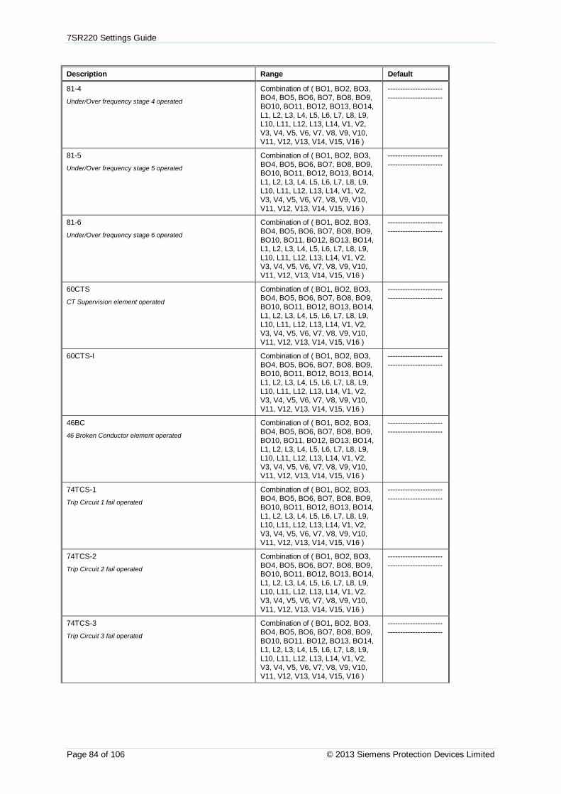
7SR220 Settings Guide
Page 84 of 106 © 2013 Siemens Protection Devices Limited
Description Range Default
81-4
Under/Over frequency stage 4 operated
Combination of ( BO1, BO2, BO3,BO4, BO5, BO6, BO7, BO8, BO9,BO10, BO11, BO12, BO13, BO14,L1, L2, L3, L4, L5, L6, L7, L8, L9,L10, L11, L12, L13, L14, V1, V2,V3, V4, V5, V6, V7, V8, V9, V10,V11, V12, V13, V14, V15, V16 )
--------------------------------------------
81-5
Under/Over frequency stage 5 operated
Combination of ( BO1, BO2, BO3,BO4, BO5, BO6, BO7, BO8, BO9,BO10, BO11, BO12, BO13, BO14,L1, L2, L3, L4, L5, L6, L7, L8, L9,L10, L11, L12, L13, L14, V1, V2,V3, V4, V5, V6, V7, V8, V9, V10,V11, V12, V13, V14, V15, V16 )
--------------------------------------------
81-6
Under/Over frequency stage 6 operated
Combination of ( BO1, BO2, BO3,BO4, BO5, BO6, BO7, BO8, BO9,BO10, BO11, BO12, BO13, BO14,L1, L2, L3, L4, L5, L6, L7, L8, L9,L10, L11, L12, L13, L14, V1, V2,V3, V4, V5, V6, V7, V8, V9, V10,V11, V12, V13, V14, V15, V16 )
--------------------------------------------
60CTS
CT Supervision element operated
Combination of ( BO1, BO2, BO3,BO4, BO5, BO6, BO7, BO8, BO9,BO10, BO11, BO12, BO13, BO14,L1, L2, L3, L4, L5, L6, L7, L8, L9,L10, L11, L12, L13, L14, V1, V2,V3, V4, V5, V6, V7, V8, V9, V10,V11, V12, V13, V14, V15, V16 )
--------------------------------------------
60CTS-I Combination of ( BO1, BO2, BO3,BO4, BO5, BO6, BO7, BO8, BO9,BO10, BO11, BO12, BO13, BO14,L1, L2, L3, L4, L5, L6, L7, L8, L9,L10, L11, L12, L13, L14, V1, V2,V3, V4, V5, V6, V7, V8, V9, V10,V11, V12, V13, V14, V15, V16 )
--------------------------------------------
46BC
46 Broken Conductor element operated
Combination of ( BO1, BO2, BO3,BO4, BO5, BO6, BO7, BO8, BO9,BO10, BO11, BO12, BO13, BO14,L1, L2, L3, L4, L5, L6, L7, L8, L9,L10, L11, L12, L13, L14, V1, V2,V3, V4, V5, V6, V7, V8, V9, V10,V11, V12, V13, V14, V15, V16 )
--------------------------------------------
74TCS-1
Trip Circuit 1 fail operated
Combination of ( BO1, BO2, BO3,BO4, BO5, BO6, BO7, BO8, BO9,BO10, BO11, BO12, BO13, BO14,L1, L2, L3, L4, L5, L6, L7, L8, L9,L10, L11, L12, L13, L14, V1, V2,V3, V4, V5, V6, V7, V8, V9, V10,V11, V12, V13, V14, V15, V16 )
--------------------------------------------
74TCS-2
Trip Circuit 2 fail operated
Combination of ( BO1, BO2, BO3,BO4, BO5, BO6, BO7, BO8, BO9,BO10, BO11, BO12, BO13, BO14,L1, L2, L3, L4, L5, L6, L7, L8, L9,L10, L11, L12, L13, L14, V1, V2,V3, V4, V5, V6, V7, V8, V9, V10,V11, V12, V13, V14, V15, V16 )
--------------------------------------------
74TCS-3
Trip Circuit 3 fail operated
Combination of ( BO1, BO2, BO3,BO4, BO5, BO6, BO7, BO8, BO9,BO10, BO11, BO12, BO13, BO14,L1, L2, L3, L4, L5, L6, L7, L8, L9,L10, L11, L12, L13, L14, V1, V2,V3, V4, V5, V6, V7, V8, V9, V10,V11, V12, V13, V14, V15, V16 )
--------------------------------------------

7SR220 Settings Guide
©2015 Siemens Protection Devices Limited Page 85 of 106
Description Range Default
74CCS-1
Close Circuit 1 fail operated
Combination of ( BO1, BO2, BO3,BO4, BO5, BO6, BO7, BO8, BO9,BO10, BO11, BO12, BO13, BO14,L1, L2, L3, L4, L5, L6, L7, L8, L9,L10, L11, L12, L13, L14, V1, V2,V3, V4, V5, V6, V7, V8, V9, V10,V11, V12, V13, V14, V15, V16 )
--------------------------------------------
74CCS-2
Close Circuit 2 fail operated
Combination of ( BO1, BO2, BO3,BO4, BO5, BO6, BO7, BO8, BO9,BO10, BO11, BO12, BO13, BO14,L1, L2, L3, L4, L5, L6, L7, L8, L9,L10, L11, L12, L13, L14, V1, V2,V3, V4, V5, V6, V7, V8, V9, V10,V11, V12, V13, V14, V15, V16 )
--------------------------------------------
74CCS-3
Close Circuit 3 fail operated
Combination of ( BO1, BO2, BO3,BO4, BO5, BO6, BO7, BO8, BO9,BO10, BO11, BO12, BO13, BO14,L1, L2, L3, L4, L5, L6, L7, L8, L9,L10, L11, L12, L13, L14, V1, V2,V3, V4, V5, V6, V7, V8, V9, V10,V11, V12, V13, V14, V15, V16 )
--------------------------------------------
81HBL2 Combination of ( BO1, BO2, BO3,BO4, BO5, BO6, BO7, BO8, BO9,BO10, BO11, BO12, BO13, BO14,L1, L2, L3, L4, L5, L6, L7, L8, L9,L10, L11, L12, L13, L14, V1, V2,V3, V4, V5, V6, V7, V8, V9, V10,V11, V12, V13, V14, V15, V16 )
--------------------------------------------
General Pickup
General Pickup operated
Combination of ( BO1, BO2, BO3,BO4, BO5, BO6, BO7, BO8, BO9,BO10, BO11, BO12, BO13, BO14,L1, L2, L3, L4, L5, L6, L7, L8, L9,L10, L11, L12, L13, L14, V1, V2,V3, V4, V5, V6, V7, V8, V9, V10,V11, V12, V13, V14, V15, V16 )
--------------------------------------------
50BF-1
Circuit Breaker Fail stage 1 operated
Combination of ( BO1, BO2, BO3,BO4, BO5, BO6, BO7, BO8, BO9,BO10, BO11, BO12, BO13, BO14,L1, L2, L3, L4, L5, L6, L7, L8, L9,L10, L11, L12, L13, L14, V1, V2,V3, V4, V5, V6, V7, V8, V9, V10,V11, V12, V13, V14, V15, V16 )
--------------------------------------------
50BF-2
Circuit Breaker Fail stage 2 operated
Combination of ( BO1, BO2, BO3,BO4, BO5, BO6, BO7, BO8, BO9,BO10, BO11, BO12, BO13, BO14,L1, L2, L3, L4, L5, L6, L7, L8, L9,L10, L11, L12, L13, L14, V1, V2,V3, V4, V5, V6, V7, V8, V9, V10,V11, V12, V13, V14, V15, V16 )
--------------------------------------------
60VTS
VT Supervision element operated
Combination of ( BO1, BO2, BO3,BO4, BO5, BO6, BO7, BO8, BO9,BO10, BO11, BO12, BO13, BO14,L1, L2, L3, L4, L5, L6, L7, L8, L9,L10, L11, L12, L13, L14, V1, V2,V3, V4, V5, V6, V7, V8, V9, V10,V11, V12, V13, V14, V15, V16 )
--------------------------------------------
60VTF-Bus
60 VTF-Bus Supervision element operated
Combination of ( BO1, BO2, BO3,BO4, BO5, BO6, BO7, BO8, BO9,BO10, BO11, BO12, BO13, BO14,L1, L2, L3, L4, L5, L6, L7, L8, L9,L10, L11, L12, L13, L14, V1, V2,V3, V4, V5, V6, V7, V8, V9, V10,V11, V12, V13, V14, V15, V16 )
--------------------------------------------

7SR220 Settings Guide
Page 86 of 106 © 2013 Siemens Protection Devices Limited
Description Range Default
50BF PhA
Circuit Breaker Fail Phase A
Combination of ( BO1, BO2, BO3,BO4, BO5, BO6, BO7, BO8, BO9,BO10, BO11, BO12, BO13, BO14,L1, L2, L3, L4, L5, L6, L7, L8, L9,L10, L11, L12, L13, L14, V1, V2,V3, V4, V5, V6, V7, V8, V9, V10,V11, V12, V13, V14, V15, V16 )
--------------------------------------------
50BF PhB
Circuit Breaker Fail Phase B
Combination of ( BO1, BO2, BO3,BO4, BO5, BO6, BO7, BO8, BO9,BO10, BO11, BO12, BO13, BO14,L1, L2, L3, L4, L5, L6, L7, L8, L9,L10, L11, L12, L13, L14, V1, V2,V3, V4, V5, V6, V7, V8, V9, V10,V11, V12, V13, V14, V15, V16 )
--------------------------------------------
50BF PhC
Circuit Breaker Fail Phase C
Combination of ( BO1, BO2, BO3,BO4, BO5, BO6, BO7, BO8, BO9,BO10, BO11, BO12, BO13, BO14,L1, L2, L3, L4, L5, L6, L7, L8, L9,L10, L11, L12, L13, L14, V1, V2,V3, V4, V5, V6, V7, V8, V9, V10,V11, V12, V13, V14, V15, V16 )
--------------------------------------------
50BF EF
Circuit Breaker Fail Earth Fault
Combination of ( BO1, BO2, BO3,BO4, BO5, BO6, BO7, BO8, BO9,BO10, BO11, BO12, BO13, BO14,L1, L2, L3, L4, L5, L6, L7, L8, L9,L10, L11, L12, L13, L14, V1, V2,V3, V4, V5, V6, V7, V8, V9, V10,V11, V12, V13, V14, V15, V16 )
--------------------------------------------
CB Total Trip Count
Total CB trip count exceeded
Combination of ( BO1, BO2, BO3,BO4, BO5, BO6, BO7, BO8, BO9,BO10, BO11, BO12, BO13, BO14,L1, L2, L3, L4, L5, L6, L7, L8, L9,L10, L11, L12, L13, L14, V1, V2,V3, V4, V5, V6, V7, V8, V9, V10,V11, V12, V13, V14, V15, V16 )
--------------------------------------------
CB Ph A Trip Count
Total CB Ph A trip count exceeded
Combination of ( BO1, BO2, BO3,BO4, BO5, BO6, BO7, BO8, BO9,BO10, BO11, BO12, BO13, BO14,L1, L2, L3, L4, L5, L6, L7, L8, L9,L10, L11, L12, L13, L14, V1, V2,V3, V4, V5, V6, V7, V8, V9, V10,V11, V12, V13, V14, V15, V16 )
--------------------------------------------
CB Ph B Trip Count
Total CB Ph B trip count exceeded
Combination of ( BO1, BO2, BO3,BO4, BO5, BO6, BO7, BO8, BO9,BO10, BO11, BO12, BO13, BO14,L1, L2, L3, L4, L5, L6, L7, L8, L9,L10, L11, L12, L13, L14, V1, V2,V3, V4, V5, V6, V7, V8, V9, V10,V11, V12, V13, V14, V15, V16 )
--------------------------------------------
CB Ph C Trip Count
Total CB Ph C trip count exceeded
Combination of ( BO1, BO2, BO3,BO4, BO5, BO6, BO7, BO8, BO9,BO10, BO11, BO12, BO13, BO14,L1, L2, L3, L4, L5, L6, L7, L8, L9,L10, L11, L12, L13, L14, V1, V2,V3, V4, V5, V6, V7, V8, V9, V10,V11, V12, V13, V14, V15, V16 )
--------------------------------------------
CB E/F Trip Count
Total CB E/F trip count exceeded
Combination of ( BO1, BO2, BO3,BO4, BO5, BO6, BO7, BO8, BO9,BO10, BO11, BO12, BO13, BO14,L1, L2, L3, L4, L5, L6, L7, L8, L9,L10, L11, L12, L13, L14, V1, V2,V3, V4, V5, V6, V7, V8, V9, V10,V11, V12, V13, V14, V15, V16 )
--------------------------------------------

7SR220 Settings Guide
©2015 Siemens Protection Devices Limited Page 87 of 106
Description Range Default
CB Delta Trip Count
Delta CB trip count exceeded
Combination of ( BO1, BO2, BO3,BO4, BO5, BO6, BO7, BO8, BO9,BO10, BO11, BO12, BO13, BO14,L1, L2, L3, L4, L5, L6, L7, L8, L9,L10, L11, L12, L13, L14, V1, V2,V3, V4, V5, V6, V7, V8, V9, V10,V11, V12, V13, V14, V15, V16 )
--------------------------------------------
CB Count To ARBlock
Count To AR Block CB trip count exceeded
Combination of ( BO1, BO2, BO3,BO4, BO5, BO6, BO7, BO8, BO9,BO10, BO11, BO12, BO13, BO14,L1, L2, L3, L4, L5, L6, L7, L8, L9,L10, L11, L12, L13, L14, V1, V2,V3, V4, V5, V6, V7, V8, V9, V10,V11, V12, V13, V14, V15, V16 )
--------------------------------------------
CB Freq Ops Count
CB Frequent Operations count exceeded
Combination of ( BO1, BO2, BO3,BO4, BO5, BO6, BO7, BO8, BO9,BO10, BO11, BO12, BO13, BO14,L1, L2, L3, L4, L5, L6, L7, L8, L9,L10, L11, L12, L13, L14, V1, V2,V3, V4, V5, V6, V7, V8, V9, V10,V11, V12, V13, V14, V15, V16 )
--------------------------------------------
I^2t CB Wear
I^2t CB Wear limit exceeded
Combination of ( BO1, BO2, BO3,BO4, BO5, BO6, BO7, BO8, BO9,BO10, BO11, BO12, BO13, BO14,L1, L2, L3, L4, L5, L6, L7, L8, L9,L10, L11, L12, L13, L14, V1, V2,V3, V4, V5, V6, V7, V8, V9, V10,V11, V12, V13, V14, V15, V16 )
--------------------------------------------
Trip Time Alarm
Trip Time Alarm operated
Combination of ( BO1, BO2, BO3,BO4, BO5, BO6, BO7, BO8, BO9,BO10, BO11, BO12, BO13, BO14,L1, L2, L3, L4, L5, L6, L7, L8, L9,L10, L11, L12, L13, L14, V1, V2,V3, V4, V5, V6, V7, V8, V9, V10,V11, V12, V13, V14, V15, V16 )
--------------------------------------------
CB Open
Indicates that the circuit breaker is in the open position.
Combination of ( BO1, BO2, BO3,BO4, BO5, BO6, BO7, BO8, BO9,BO10, BO11, BO12, BO13, BO14,L1, L2, L3, L4, L5, L6, L7, L8, L9,L10, L11, L12, L13, L14, V1, V2,V3, V4, V5, V6, V7, V8, V9, V10,V11, V12, V13, V14, V15, V16 )
--------------------------------------------
CB Closed
Indicates that the circuit breaker is in the closed position.
Combination of ( BO1, BO2, BO3,BO4, BO5, BO6, BO7, BO8, BO9,BO10, BO11, BO12, BO13, BO14,L1, L2, L3, L4, L5, L6, L7, L8, L9,L10, L11, L12, L13, L14, V1, V2,V3, V4, V5, V6, V7, V8, V9, V10,V11, V12, V13, V14, V15, V16 )
--------------------------------------------
Close CB Blocked
Indicates that the Close CB control is blocked by itsinterlocking logic.
Combination of ( BO1, BO2, BO3,BO4, BO5, BO6, BO7, BO8, BO9,BO10, BO11, BO12, BO13, BO14,L1, L2, L3, L4, L5, L6, L7, L8, L9,L10, L11, L12, L13, L14, V1, V2,V3, V4, V5, V6, V7, V8, V9, V10,V11, V12, V13, V14, V15, V16 )
--------------------------------------------
CB Alarm
Indicates the CB is either in an illegal state or is stuck neitheropen or closed.
Combination of ( BO1, BO2, BO3,BO4, BO5, BO6, BO7, BO8, BO9,BO10, BO11, BO12, BO13, BO14,L1, L2, L3, L4, L5, L6, L7, L8, L9,L10, L11, L12, L13, L14, V1, V2,V3, V4, V5, V6, V7, V8, V9, V10,V11, V12, V13, V14, V15, V16 )
--------------------------------------------

7SR220 Settings Guide
Page 88 of 106 © 2013 Siemens Protection Devices Limited
Description Range Default
Open CB
Open pulse due to Manual Open being issued.
Combination of ( BO1, BO2, BO3,BO4, BO5, BO6, BO7, BO8, BO9,BO10, BO11, BO12, BO13, BO14,L1, L2, L3, L4, L5, L6, L7, L8, L9,L10, L11, L12, L13, L14, V1, V2,V3, V4, V5, V6, V7, V8, V9, V10,V11, V12, V13, V14, V15, V16 )
--------------------------------------------
Phase A
Phase A element operated
Combination of ( BO1, BO2, BO3,BO4, BO5, BO6, BO7, BO8, BO9,BO10, BO11, BO12, BO13, BO14,L1, L2, L3, L4, L5, L6, L7, L8, L9,L10, L11, L12, L13, L14, V1, V2,V3, V4, V5, V6, V7, V8, V9, V10,V11, V12, V13, V14, V15, V16 )
--------------------------------------------
Phase B
Phase B element operated
Combination of ( BO1, BO2, BO3,BO4, BO5, BO6, BO7, BO8, BO9,BO10, BO11, BO12, BO13, BO14,L1, L2, L3, L4, L5, L6, L7, L8, L9,L10, L11, L12, L13, L14, V1, V2,V3, V4, V5, V6, V7, V8, V9, V10,V11, V12, V13, V14, V15, V16 )
--------------------------------------------
Phase C
Phase C element operated
Combination of ( BO1, BO2, BO3,BO4, BO5, BO6, BO7, BO8, BO9,BO10, BO11, BO12, BO13, BO14,L1, L2, L3, L4, L5, L6, L7, L8, L9,L10, L11, L12, L13, L14, V1, V2,V3, V4, V5, V6, V7, V8, V9, V10,V11, V12, V13, V14, V15, V16 )
--------------------------------------------
Derived E/F
Derive E/F element operated
Combination of ( BO1, BO2, BO3,BO4, BO5, BO6, BO7, BO8, BO9,BO10, BO11, BO12, BO13, BO14,L1, L2, L3, L4, L5, L6, L7, L8, L9,L10, L11, L12, L13, L14, V1, V2,V3, V4, V5, V6, V7, V8, V9, V10,V11, V12, V13, V14, V15, V16 )
--------------------------------------------
Measured E/F
Measured E/F element operated
Combination of ( BO1, BO2, BO3,BO4, BO5, BO6, BO7, BO8, BO9,BO10, BO11, BO12, BO13, BO14,L1, L2, L3, L4, L5, L6, L7, L8, L9,L10, L11, L12, L13, L14, V1, V2,V3, V4, V5, V6, V7, V8, V9, V10,V11, V12, V13, V14, V15, V16 )
--------------------------------------------
Sensitive E/F
Sensitive E/F element operated
Combination of ( BO1, BO2, BO3,BO4, BO5, BO6, BO7, BO8, BO9,BO10, BO11, BO12, BO13, BO14,L1, L2, L3, L4, L5, L6, L7, L8, L9,L10, L11, L12, L13, L14, V1, V2,V3, V4, V5, V6, V7, V8, V9, V10,V11, V12, V13, V14, V15, V16 )
--------------------------------------------
Start Count Alarm Combination of ( BO1, BO2, BO3,BO4, BO5, BO6, BO7, BO8, BO9,BO10, BO11, BO12, BO13, BO14,L1, L2, L3, L4, L5, L6, L7, L8, L9,L10, L11, L12, L13, L14, V1, V2,V3, V4, V5, V6, V7, V8, V9, V10,V11, V12, V13, V14, V15, V16 )
--------------------------------------------
50AFD PhA
Arc Flash Detector Phase A operated
Combination of ( BO1, BO2, BO3,BO4, BO5, BO6, BO7, BO8, BO9,BO10, BO11, BO12, BO13, BO14,L1, L2, L3, L4, L5, L6, L7, L8, L9,L10, L11, L12, L13, L14, V1, V2,V3, V4, V5, V6, V7, V8, V9, V10,V11, V12, V13, V14, V15, V16 )
--------------------------------------------

7SR220 Settings Guide
©2015 Siemens Protection Devices Limited Page 89 of 106
Description Range Default
50AFD PhB
Arc Flash Detector Phase B operated
Combination of ( BO1, BO2, BO3,BO4, BO5, BO6, BO7, BO8, BO9,BO10, BO11, BO12, BO13, BO14,L1, L2, L3, L4, L5, L6, L7, L8, L9,L10, L11, L12, L13, L14, V1, V2,V3, V4, V5, V6, V7, V8, V9, V10,V11, V12, V13, V14, V15, V16 )
--------------------------------------------
50AFD PhC
Arc Flash Detector Phase C operated
Combination of ( BO1, BO2, BO3,BO4, BO5, BO6, BO7, BO8, BO9,BO10, BO11, BO12, BO13, BO14,L1, L2, L3, L4, L5, L6, L7, L8, L9,L10, L11, L12, L13, L14, V1, V2,V3, V4, V5, V6, V7, V8, V9, V10,V11, V12, V13, V14, V15, V16 )
--------------------------------------------
50AFD Combination of ( BO1, BO2, BO3,BO4, BO5, BO6, BO7, BO8, BO9,BO10, BO11, BO12, BO13, BO14,L1, L2, L3, L4, L5, L6, L7, L8, L9,L10, L11, L12, L13, L14, V1, V2,V3, V4, V5, V6, V7, V8, V9, V10,V11, V12, V13, V14, V15, V16 )
--------------------------------------------
AFD Zone 1 Flash Combination of ( BO1, BO2, BO3,BO4, BO5, BO6, BO7, BO8, BO9,BO10, BO11, BO12, BO13, BO14,L1, L2, L3, L4, L5, L6, L7, L8, L9,L10, L11, L12, L13, L14, V1, V2,V3, V4, V5, V6, V7, V8, V9, V10,V11, V12, V13, V14, V15, V16 )
--------------------------------------------
AFD Zone 1 Combination of ( BO1, BO2, BO3,BO4, BO5, BO6, BO7, BO8, BO9,BO10, BO11, BO12, BO13, BO14,L1, L2, L3, L4, L5, L6, L7, L8, L9,L10, L11, L12, L13, L14, V1, V2,V3, V4, V5, V6, V7, V8, V9, V10,V11, V12, V13, V14, V15, V16 )
--------------------------------------------
AFD Zone 2 Flash Combination of ( BO1, BO2, BO3,BO4, BO5, BO6, BO7, BO8, BO9,BO10, BO11, BO12, BO13, BO14,L1, L2, L3, L4, L5, L6, L7, L8, L9,L10, L11, L12, L13, L14, V1, V2,V3, V4, V5, V6, V7, V8, V9, V10,V11, V12, V13, V14, V15, V16 )
--------------------------------------------
AFD Zone 2 Combination of ( BO1, BO2, BO3,BO4, BO5, BO6, BO7, BO8, BO9,BO10, BO11, BO12, BO13, BO14,L1, L2, L3, L4, L5, L6, L7, L8, L9,L10, L11, L12, L13, L14, V1, V2,V3, V4, V5, V6, V7, V8, V9, V10,V11, V12, V13, V14, V15, V16 )
--------------------------------------------
AFD Zone 3 Flash Combination of ( BO1, BO2, BO3,BO4, BO5, BO6, BO7, BO8, BO9,BO10, BO11, BO12, BO13, BO14,L1, L2, L3, L4, L5, L6, L7, L8, L9,L10, L11, L12, L13, L14, V1, V2,V3, V4, V5, V6, V7, V8, V9, V10,V11, V12, V13, V14, V15, V16 )
--------------------------------------------
AFD Zone 3 Combination of ( BO1, BO2, BO3,BO4, BO5, BO6, BO7, BO8, BO9,BO10, BO11, BO12, BO13, BO14,L1, L2, L3, L4, L5, L6, L7, L8, L9,L10, L11, L12, L13, L14, V1, V2,V3, V4, V5, V6, V7, V8, V9, V10,V11, V12, V13, V14, V15, V16 )
--------------------------------------------

7SR220 Settings Guide
Page 90 of 106 © 2013 Siemens Protection Devices Limited
Description Range Default
AFD Zone 4 Flash Combination of ( BO1, BO2, BO3,BO4, BO5, BO6, BO7, BO8, BO9,BO10, BO11, BO12, BO13, BO14,L1, L2, L3, L4, L5, L6, L7, L8, L9,L10, L11, L12, L13, L14, V1, V2,V3, V4, V5, V6, V7, V8, V9, V10,V11, V12, V13, V14, V15, V16 )
--------------------------------------------
AFD Zone 4 Combination of ( BO1, BO2, BO3,BO4, BO5, BO6, BO7, BO8, BO9,BO10, BO11, BO12, BO13, BO14,L1, L2, L3, L4, L5, L6, L7, L8, L9,L10, L11, L12, L13, L14, V1, V2,V3, V4, V5, V6, V7, V8, V9, V10,V11, V12, V13, V14, V15, V16 )
--------------------------------------------
AFD Zone 5 Flash Combination of ( BO1, BO2, BO3,BO4, BO5, BO6, BO7, BO8, BO9,BO10, BO11, BO12, BO13, BO14,L1, L2, L3, L4, L5, L6, L7, L8, L9,L10, L11, L12, L13, L14, V1, V2,V3, V4, V5, V6, V7, V8, V9, V10,V11, V12, V13, V14, V15, V16 )
--------------------------------------------
AFD Zone 5 Combination of ( BO1, BO2, BO3,BO4, BO5, BO6, BO7, BO8, BO9,BO10, BO11, BO12, BO13, BO14,L1, L2, L3, L4, L5, L6, L7, L8, L9,L10, L11, L12, L13, L14, V1, V2,V3, V4, V5, V6, V7, V8, V9, V10,V11, V12, V13, V14, V15, V16 )
--------------------------------------------
AFD Zone 6 Flash Combination of ( BO1, BO2, BO3,BO4, BO5, BO6, BO7, BO8, BO9,BO10, BO11, BO12, BO13, BO14,L1, L2, L3, L4, L5, L6, L7, L8, L9,L10, L11, L12, L13, L14, V1, V2,V3, V4, V5, V6, V7, V8, V9, V10,V11, V12, V13, V14, V15, V16 )
--------------------------------------------
AFD Zone 6 Combination of ( BO1, BO2, BO3,BO4, BO5, BO6, BO7, BO8, BO9,BO10, BO11, BO12, BO13, BO14,L1, L2, L3, L4, L5, L6, L7, L8, L9,L10, L11, L12, L13, L14, V1, V2,V3, V4, V5, V6, V7, V8, V9, V10,V11, V12, V13, V14, V15, V16 )
--------------------------------------------
User Output 1
User Output 1 operated
Combination of ( BO1, BO2, BO3,BO4, BO5, BO6, BO7, BO8, BO9,BO10, BO11, BO12, BO13, BO14,L1, L2, L3, L4, L5, L6, L7, L8, L9,L10, L11, L12, L13, L14, V1, V2,V3, V4, V5, V6, V7, V8, V9, V10,V11, V12, V13, V14, V15, V16 )
--------------------------------------------
---
User Output 32
User Output 32 operated
Combination of ( BO1, BO2, BO3,BO4, BO5, BO6, BO7, BO8, BO9,BO10, BO11, BO12, BO13, BO14,L1, L2, L3, L4, L5, L6, L7, L8, L9,L10, L11, L12, L13, L14, V1, V2,V3, V4, V5, V6, V7, V8, V9, V10,V11, V12, V13, V14, V15, V16 )
--------------------------------------------
En100 Life
Raised when the En100 is communicating correctly with theProtection CPU
Combination of ( BO1, BO2, BO3,BO4, BO5, BO6, BO7, BO8, BO9,BO10, BO11, BO12, BO13, BO14,L1, L2, L3, L4, L5, L6, L7, L8, L9,L10, L11, L12, L13, L14, V1, V2,V3, V4, V5, V6, V7, V8, V9, V10,V11, V12, V13, V14, V15, V16 )
--------------------------------------------
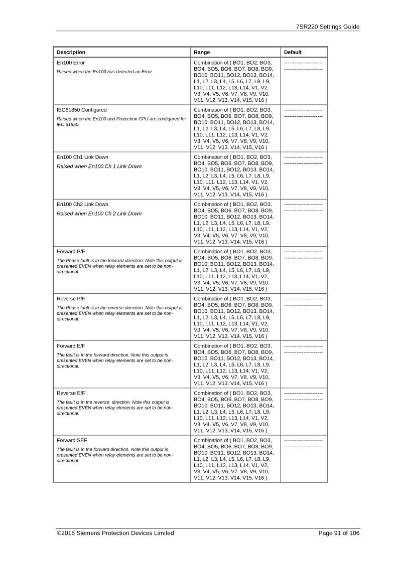
7SR220 Settings Guide
©2015 Siemens Protection Devices Limited Page 91 of 106
Description Range Default
En100 Error
Raised when the En100 has detected an Error
Combination of ( BO1, BO2, BO3,BO4, BO5, BO6, BO7, BO8, BO9,BO10, BO11, BO12, BO13, BO14,L1, L2, L3, L4, L5, L6, L7, L8, L9,L10, L11, L12, L13, L14, V1, V2,V3, V4, V5, V6, V7, V8, V9, V10,V11, V12, V13, V14, V15, V16 )
--------------------------------------------
IEC61850 Configured
Raised when the En100 and Protection CPU are configured forIEC 61850.
Combination of ( BO1, BO2, BO3,BO4, BO5, BO6, BO7, BO8, BO9,BO10, BO11, BO12, BO13, BO14,L1, L2, L3, L4, L5, L6, L7, L8, L9,L10, L11, L12, L13, L14, V1, V2,V3, V4, V5, V6, V7, V8, V9, V10,V11, V12, V13, V14, V15, V16 )
--------------------------------------------
En100 Ch1 Link Down
Raised when En100 Ch 1 Link Down
Combination of ( BO1, BO2, BO3,BO4, BO5, BO6, BO7, BO8, BO9,BO10, BO11, BO12, BO13, BO14,L1, L2, L3, L4, L5, L6, L7, L8, L9,L10, L11, L12, L13, L14, V1, V2,V3, V4, V5, V6, V7, V8, V9, V10,V11, V12, V13, V14, V15, V16 )
--------------------------------------------
En100 Ch2 Link Down
Raised when En100 Ch 2 Link Down
Combination of ( BO1, BO2, BO3,BO4, BO5, BO6, BO7, BO8, BO9,BO10, BO11, BO12, BO13, BO14,L1, L2, L3, L4, L5, L6, L7, L8, L9,L10, L11, L12, L13, L14, V1, V2,V3, V4, V5, V6, V7, V8, V9, V10,V11, V12, V13, V14, V15, V16 )
--------------------------------------------
Forward P/F
The Phase fault is in the forward direction. Note this output ispresented EVEN when relay elements are set to be non-directional.
Combination of ( BO1, BO2, BO3,BO4, BO5, BO6, BO7, BO8, BO9,BO10, BO11, BO12, BO13, BO14,L1, L2, L3, L4, L5, L6, L7, L8, L9,L10, L11, L12, L13, L14, V1, V2,V3, V4, V5, V6, V7, V8, V9, V10,V11, V12, V13, V14, V15, V16 )
--------------------------------------------
Reverse P/F
The Phase fault is in the reverse direction. Note this output ispresented EVEN when relay elements are set to be non-directional.
Combination of ( BO1, BO2, BO3,BO4, BO5, BO6, BO7, BO8, BO9,BO10, BO11, BO12, BO13, BO14,L1, L2, L3, L4, L5, L6, L7, L8, L9,L10, L11, L12, L13, L14, V1, V2,V3, V4, V5, V6, V7, V8, V9, V10,V11, V12, V13, V14, V15, V16 )
--------------------------------------------
Forward E/F
The fault is in the forward direction. Note this output ispresented EVEN when relay elements are set to be non-directional.
Combination of ( BO1, BO2, BO3,BO4, BO5, BO6, BO7, BO8, BO9,BO10, BO11, BO12, BO13, BO14,L1, L2, L3, L4, L5, L6, L7, L8, L9,L10, L11, L12, L13, L14, V1, V2,V3, V4, V5, V6, V7, V8, V9, V10,V11, V12, V13, V14, V15, V16 )
--------------------------------------------
Reverse E/F
The fault is in the reverse direction. Note this output ispresented EVEN when relay elements are set to be non-directional.
Combination of ( BO1, BO2, BO3,BO4, BO5, BO6, BO7, BO8, BO9,BO10, BO11, BO12, BO13, BO14,L1, L2, L3, L4, L5, L6, L7, L8, L9,L10, L11, L12, L13, L14, V1, V2,V3, V4, V5, V6, V7, V8, V9, V10,V11, V12, V13, V14, V15, V16 )
--------------------------------------------
Forward SEF
The fault is in the forward direction. Note this output ispresented EVEN when relay elements are set to be non-directional.
Combination of ( BO1, BO2, BO3,BO4, BO5, BO6, BO7, BO8, BO9,BO10, BO11, BO12, BO13, BO14,L1, L2, L3, L4, L5, L6, L7, L8, L9,L10, L11, L12, L13, L14, V1, V2,V3, V4, V5, V6, V7, V8, V9, V10,V11, V12, V13, V14, V15, V16 )
--------------------------------------------

7SR220 Settings Guide
Page 92 of 106 © 2013 Siemens Protection Devices Limited
Description Range Default
Reverse SEF
The fault is in the reverse direction. Note this output ispresented EVEN when relay elements are set to be non-directional.
Combination of ( BO1, BO2, BO3,BO4, BO5, BO6, BO7, BO8, BO9,BO10, BO11, BO12, BO13, BO14,L1, L2, L3, L4, L5, L6, L7, L8, L9,L10, L11, L12, L13, L14, V1, V2,V3, V4, V5, V6, V7, V8, V9, V10,V11, V12, V13, V14, V15, V16 )
--------------------------------------------
Manual Close CB
Close pulse due to Manual close being issued
Combination of ( BO1, BO2, BO3,BO4, BO5, BO6, BO7, BO8, BO9,BO10, BO11, BO12, BO13, BO14,L1, L2, L3, L4, L5, L6, L7, L8, L9,L10, L11, L12, L13, L14, V1, V2,V3, V4, V5, V6, V7, V8, V9, V10,V11, V12, V13, V14, V15, V16 )
BO8
79 AR Close CB
Close pulse due to auto-reclose sequence
Combination of ( BO1, BO2, BO3,BO4, BO5, BO6, BO7, BO8, BO9,BO10, BO11, BO12, BO13, BO14,L1, L2, L3, L4, L5, L6, L7, L8, L9,L10, L11, L12, L13, L14, V1, V2,V3, V4, V5, V6, V7, V8, V9, V10,V11, V12, V13, V14, V15, V16 )
--------------------------------------------
79 Trip & Reclose
Indicates the Trip & Reclose sequence being performed
Combination of ( BO1, BO2, BO3,BO4, BO5, BO6, BO7, BO8, BO9,BO10, BO11, BO12, BO13, BO14,L1, L2, L3, L4, L5, L6, L7, L8, L9,L10, L11, L12, L13, L14, V1, V2,V3, V4, V5, V6, V7, V8, V9, V10,V11, V12, V13, V14, V15, V16 )
--------------------------------------------
79 Trip & Lockout
Indicates the Trip & Lockout sequence being performed
Combination of ( BO1, BO2, BO3,BO4, BO5, BO6, BO7, BO8, BO9,BO10, BO11, BO12, BO13, BO14,L1, L2, L3, L4, L5, L6, L7, L8, L9,L10, L11, L12, L13, L14, V1, V2,V3, V4, V5, V6, V7, V8, V9, V10,V11, V12, V13, V14, V15, V16 )
--------------------------------------------
79 Lockout
Indicates the auto-recloser is in the Lockout state
Combination of ( BO1, BO2, BO3,BO4, BO5, BO6, BO7, BO8, BO9,BO10, BO11, BO12, BO13, BO14,L1, L2, L3, L4, L5, L6, L7, L8, L9,L10, L11, L12, L13, L14, V1, V2,V3, V4, V5, V6, V7, V8, V9, V10,V11, V12, V13, V14, V15, V16 )
--------------------------------------------
79 Out Of Service
Indicates the auto-recloser is out of service
Combination of ( BO1, BO2, BO3,BO4, BO5, BO6, BO7, BO8, BO9,BO10, BO11, BO12, BO13, BO14,L1, L2, L3, L4, L5, L6, L7, L8, L9,L10, L11, L12, L13, L14, V1, V2,V3, V4, V5, V6, V7, V8, V9, V10,V11, V12, V13, V14, V15, V16 )
--------------------------------------------
79 In Service
Indicates the auto-recloser is in service
Combination of ( BO1, BO2, BO3,BO4, BO5, BO6, BO7, BO8, BO9,BO10, BO11, BO12, BO13, BO14,L1, L2, L3, L4, L5, L6, L7, L8, L9,L10, L11, L12, L13, L14, V1, V2,V3, V4, V5, V6, V7, V8, V9, V10,V11, V12, V13, V14, V15, V16 )
--------------------------------------------
79 In Progress
Indicates an auto-reclose sequence is in progress
Combination of ( BO1, BO2, BO3,BO4, BO5, BO6, BO7, BO8, BO9,BO10, BO11, BO12, BO13, BO14,L1, L2, L3, L4, L5, L6, L7, L8, L9,L10, L11, L12, L13, L14, V1, V2,V3, V4, V5, V6, V7, V8, V9, V10,V11, V12, V13, V14, V15, V16 )
--------------------------------------------

7SR220 Settings Guide
©2015 Siemens Protection Devices Limited Page 93 of 106
Description Range Default
79 Block Extern
Indicates that Extern for the current shot has been selected tobe delayed. (This may be used to block external trippingelements in the same way as the internal protection elementsare blocked to achieve Instantaneous / Delayed operation.)
Combination of ( BO1, BO2, BO3,BO4, BO5, BO6, BO7, BO8, BO9,BO10, BO11, BO12, BO13, BO14,L1, L2, L3, L4, L5, L6, L7, L8, L9,L10, L11, L12, L13, L14, V1, V2,V3, V4, V5, V6, V7, V8, V9, V10,V11, V12, V13, V14, V15, V16 )
--------------------------------------------
79 CB Fail To Close
Indicates the CB was not closed at the end of the Close Pulse
Combination of ( BO1, BO2, BO3,BO4, BO5, BO6, BO7, BO8, BO9,BO10, BO11, BO12, BO13, BO14,L1, L2, L3, L4, L5, L6, L7, L8, L9,L10, L11, L12, L13, L14, V1, V2,V3, V4, V5, V6, V7, V8, V9, V10,V11, V12, V13, V14, V15, V16 )
--------------------------------------------
79 Close Onto Fault
Indicates an element starter or trip operated during the ClosePulse
Combination of ( BO1, BO2, BO3,BO4, BO5, BO6, BO7, BO8, BO9,BO10, BO11, BO12, BO13, BO14,L1, L2, L3, L4, L5, L6, L7, L8, L9,L10, L11, L12, L13, L14, V1, V2,V3, V4, V5, V6, V7, V8, V9, V10,V11, V12, V13, V14, V15, V16 )
--------------------------------------------
79 Successful AR
Indicates that after a reclose and at the end of the Reclaimtime the CB was closed and there were no auto-reclose tripelements operated. (This is issued for 2 secs)
Combination of ( BO1, BO2, BO3,BO4, BO5, BO6, BO7, BO8, BO9,BO10, BO11, BO12, BO13, BO14,L1, L2, L3, L4, L5, L6, L7, L8, L9,L10, L11, L12, L13, L14, V1, V2,V3, V4, V5, V6, V7, V8, V9, V10,V11, V12, V13, V14, V15, V16 )
--------------------------------------------
Successful Man Close
Indicates that after a manual close and at the end of theReclaim time the CB was closed and there were no auto-reclose trip elements operated. (This is issued for 2 secs)
Combination of ( BO1, BO2, BO3,BO4, BO5, BO6, BO7, BO8, BO9,BO10, BO11, BO12, BO13, BO14,L1, L2, L3, L4, L5, L6, L7, L8, L9,L10, L11, L12, L13, L14, V1, V2,V3, V4, V5, V6, V7, V8, V9, V10,V11, V12, V13, V14, V15, V16 )
--------------------------------------------
Man Override Sync Combination of ( BO1, BO2, BO3,BO4, BO5, BO6, BO7, BO8, BO9,BO10, BO11, BO12, BO13, BO14,L1, L2, L3, L4, L5, L6, L7, L8, L9,L10, L11, L12, L13, L14, V1, V2,V3, V4, V5, V6, V7, V8, V9, V10,V11, V12, V13, V14, V15, V16 )
--------------------------------------------
79 Override Sync Combination of ( BO1, BO2, BO3,BO4, BO5, BO6, BO7, BO8, BO9,BO10, BO11, BO12, BO13, BO14,L1, L2, L3, L4, L5, L6, L7, L8, L9,L10, L11, L12, L13, L14, V1, V2,V3, V4, V5, V6, V7, V8, V9, V10,V11, V12, V13, V14, V15, V16 )
--------------------------------------------
25 Live Line Combination of ( BO1, BO2, BO3,BO4, BO5, BO6, BO7, BO8, BO9,BO10, BO11, BO12, BO13, BO14,L1, L2, L3, L4, L5, L6, L7, L8, L9,L10, L11, L12, L13, L14, V1, V2,V3, V4, V5, V6, V7, V8, V9, V10,V11, V12, V13, V14, V15, V16 )
--------------------------------------------
25 Live bus Combination of ( BO1, BO2, BO3,BO4, BO5, BO6, BO7, BO8, BO9,BO10, BO11, BO12, BO13, BO14,L1, L2, L3, L4, L5, L6, L7, L8, L9,L10, L11, L12, L13, L14, V1, V2,V3, V4, V5, V6, V7, V8, V9, V10,V11, V12, V13, V14, V15, V16 )
--------------------------------------------

7SR220 Settings Guide
Page 94 of 106 © 2013 Siemens Protection Devices Limited
Description Range Default
25 Line U/V Combination of ( BO1, BO2, BO3,BO4, BO5, BO6, BO7, BO8, BO9,BO10, BO11, BO12, BO13, BO14,L1, L2, L3, L4, L5, L6, L7, L8, L9,L10, L11, L12, L13, L14, V1, V2,V3, V4, V5, V6, V7, V8, V9, V10,V11, V12, V13, V14, V15, V16 )
--------------------------------------------
25 Bus U/V Combination of ( BO1, BO2, BO3,BO4, BO5, BO6, BO7, BO8, BO9,BO10, BO11, BO12, BO13, BO14,L1, L2, L3, L4, L5, L6, L7, L8, L9,L10, L11, L12, L13, L14, V1, V2,V3, V4, V5, V6, V7, V8, V9, V10,V11, V12, V13, V14, V15, V16 )
--------------------------------------------
25 Diff Voltage Combination of ( BO1, BO2, BO3,BO4, BO5, BO6, BO7, BO8, BO9,BO10, BO11, BO12, BO13, BO14,L1, L2, L3, L4, L5, L6, L7, L8, L9,L10, L11, L12, L13, L14, V1, V2,V3, V4, V5, V6, V7, V8, V9, V10,V11, V12, V13, V14, V15, V16 )
--------------------------------------------
25 Voltage Check Combination of ( BO1, BO2, BO3,BO4, BO5, BO6, BO7, BO8, BO9,BO10, BO11, BO12, BO13, BO14,L1, L2, L3, L4, L5, L6, L7, L8, L9,L10, L11, L12, L13, L14, V1, V2,V3, V4, V5, V6, V7, V8, V9, V10,V11, V12, V13, V14, V15, V16 )
--------------------------------------------
25 In Sync Combination of ( BO1, BO2, BO3,BO4, BO5, BO6, BO7, BO8, BO9,BO10, BO11, BO12, BO13, BO14,L1, L2, L3, L4, L5, L6, L7, L8, L9,L10, L11, L12, L13, L14, V1, V2,V3, V4, V5, V6, V7, V8, V9, V10,V11, V12, V13, V14, V15, V16 )
--------------------------------------------
25 CS In Progress Combination of ( BO1, BO2, BO3,BO4, BO5, BO6, BO7, BO8, BO9,BO10, BO11, BO12, BO13, BO14,L1, L2, L3, L4, L5, L6, L7, L8, L9,L10, L11, L12, L13, L14, V1, V2,V3, V4, V5, V6, V7, V8, V9, V10,V11, V12, V13, V14, V15, V16 )
--------------------------------------------
25 SS In Progress Combination of ( BO1, BO2, BO3,BO4, BO5, BO6, BO7, BO8, BO9,BO10, BO11, BO12, BO13, BO14,L1, L2, L3, L4, L5, L6, L7, L8, L9,L10, L11, L12, L13, L14, V1, V2,V3, V4, V5, V6, V7, V8, V9, V10,V11, V12, V13, V14, V15, V16 )
--------------------------------------------
25 COZ In Progress Combination of ( BO1, BO2, BO3,BO4, BO5, BO6, BO7, BO8, BO9,BO10, BO11, BO12, BO13, BO14,L1, L2, L3, L4, L5, L6, L7, L8, L9,L10, L11, L12, L13, L14, V1, V2,V3, V4, V5, V6, V7, V8, V9, V10,V11, V12, V13, V14, V15, V16 )
--------------------------------------------
25 System Split LO Combination of ( BO1, BO2, BO3,BO4, BO5, BO6, BO7, BO8, BO9,BO10, BO11, BO12, BO13, BO14,L1, L2, L3, L4, L5, L6, L7, L8, L9,L10, L11, L12, L13, L14, V1, V2,V3, V4, V5, V6, V7, V8, V9, V10,V11, V12, V13, V14, V15, V16 )
--------------------------------------------

7SR220 Settings Guide
©2015 Siemens Protection Devices Limited Page 95 of 106
Description Range Default
Hot Line Working
Indicates that Hot LineWorking functionality has been selected
Combination of ( BO1, BO2, BO3,BO4, BO5, BO6, BO7, BO8, BO9,BO10, BO11, BO12, BO13, BO14,L1, L2, L3, L4, L5, L6, L7, L8, L9,L10, L11, L12, L13, L14, V1, V2,V3, V4, V5, V6, V7, V8, V9, V10,V11, V12, V13, V14, V15, V16 )
--------------------------------------------
Inst Prot'n Out
Indicates that the protection elements selected to beInstantaneous elements are switched out
Combination of ( BO1, BO2, BO3,BO4, BO5, BO6, BO7, BO8, BO9,BO10, BO11, BO12, BO13, BO14,L1, L2, L3, L4, L5, L6, L7, L8, L9,L10, L11, L12, L13, L14, V1, V2,V3, V4, V5, V6, V7, V8, V9, V10,V11, V12, V13, V14, V15, V16 )
--------------------------------------------
E/F Out
Indicates that the instantaneous protection elements areswitched out.
Combination of ( BO1, BO2, BO3,BO4, BO5, BO6, BO7, BO8, BO9,BO10, BO11, BO12, BO13, BO14,L1, L2, L3, L4, L5, L6, L7, L8, L9,L10, L11, L12, L13, L14, V1, V2,V3, V4, V5, V6, V7, V8, V9, V10,V11, V12, V13, V14, V15, V16 )
--------------------------------------------
SEF Out
Indicates that the SEF protection elements are switched out
Combination of ( BO1, BO2, BO3,BO4, BO5, BO6, BO7, BO8, BO9,BO10, BO11, BO12, BO13, BO14,L1, L2, L3, L4, L5, L6, L7, L8, L9,L10, L11, L12, L13, L14, V1, V2,V3, V4, V5, V6, V7, V8, V9, V10,V11, V12, V13, V14, V15, V16 )
--------------------------------------------
New Wave Stored
The waveform recorder has stored new information Note: thisis a pulsed output
Combination of ( BO1, BO2, BO3,BO4, BO5, BO6, BO7, BO8, BO9,BO10, BO11, BO12, BO13, BO14,L1, L2, L3, L4, L5, L6, L7, L8, L9,L10, L11, L12, L13, L14, V1, V2,V3, V4, V5, V6, V7, V8, V9, V10,V11, V12, V13, V14, V15, V16 )
--------------------------------------------
New Fault Stored
The fault recorder has stored new information Note: this is apulsed output
Combination of ( BO1, BO2, BO3,BO4, BO5, BO6, BO7, BO8, BO9,BO10, BO11, BO12, BO13, BO14,L1, L2, L3, L4, L5, L6, L7, L8, L9,L10, L11, L12, L13, L14, V1, V2,V3, V4, V5, V6, V7, V8, V9, V10,V11, V12, V13, V14, V15, V16 )
--------------------------------------------
Active Exp Pulse Combination of ( BO1, BO2, BO3,BO4, BO5, BO6, BO7, BO8, BO9,BO10, BO11, BO12, BO13, BO14,L1, L2, L3, L4, L5, L6, L7, L8, L9,L10, L11, L12, L13, L14, V1, V2,V3, V4, V5, V6, V7, V8, V9, V10,V11, V12, V13, V14, V15, V16 )
--------------------------------------------
Active Imp Pulse Combination of ( BO1, BO2, BO3,BO4, BO5, BO6, BO7, BO8, BO9,BO10, BO11, BO12, BO13, BO14,L1, L2, L3, L4, L5, L6, L7, L8, L9,L10, L11, L12, L13, L14, V1, V2,V3, V4, V5, V6, V7, V8, V9, V10,V11, V12, V13, V14, V15, V16 )
--------------------------------------------
Reactive Exp Pulse Combination of ( BO1, BO2, BO3,BO4, BO5, BO6, BO7, BO8, BO9,BO10, BO11, BO12, BO13, BO14,L1, L2, L3, L4, L5, L6, L7, L8, L9,L10, L11, L12, L13, L14, V1, V2,V3, V4, V5, V6, V7, V8, V9, V10,V11, V12, V13, V14, V15, V16 )
--------------------------------------------

7SR220 Settings Guide
Page 96 of 106 © 2013 Siemens Protection Devices Limited
Description Range Default
Reactive Imp Pulse Combination of ( BO1, BO2, BO3,BO4, BO5, BO6, BO7, BO8, BO9,BO10, BO11, BO12, BO13, BO14,L1, L2, L3, L4, L5, L6, L7, L8, L9,L10, L11, L12, L13, L14, V1, V2,V3, V4, V5, V6, V7, V8, V9, V10,V11, V12, V13, V14, V15, V16 )
--------------------------------------------
Out Of Service Mode
Indicates the relay is in Out Of Service Mode
Combination of ( BO1, BO2, BO3,BO4, BO5, BO6, BO7, BO8, BO9,BO10, BO11, BO12, BO13, BO14,L1, L2, L3, L4, L5, L6, L7, L8, L9,L10, L11, L12, L13, L14, V1, V2,V3, V4, V5, V6, V7, V8, V9, V10,V11, V12, V13, V14, V15, V16 )
--------------------------------------------
Local Mode
Indicates the relay is in Local Mode
Combination of ( BO1, BO2, BO3,BO4, BO5, BO6, BO7, BO8, BO9,BO10, BO11, BO12, BO13, BO14,L1, L2, L3, L4, L5, L6, L7, L8, L9,L10, L11, L12, L13, L14, V1, V2,V3, V4, V5, V6, V7, V8, V9, V10,V11, V12, V13, V14, V15, V16 )
--------------------------------------------
Remote Mode
Indicates the relay is in Remote Mode
Combination of ( BO1, BO2, BO3,BO4, BO5, BO6, BO7, BO8, BO9,BO10, BO11, BO12, BO13, BO14,L1, L2, L3, L4, L5, L6, L7, L8, L9,L10, L11, L12, L13, L14, V1, V2,V3, V4, V5, V6, V7, V8, V9, V10,V11, V12, V13, V14, V15, V16 )
--------------------------------------------
BI 1 Operated
DC Binary Input 1 has operated
Combination of ( BO1, BO2, BO3,BO4, BO5, BO6, BO7, BO8, BO9,BO10, BO11, BO12, BO13, BO14,L1, L2, L3, L4, L5, L6, L7, L8, L9,L10, L11, L12, L13, L14, V1, V2,V3, V4, V5, V6, V7, V8, V9, V10,V11, V12, V13, V14, V15, V16 )
--------------------------------------------
BI 2 Operated
DC Binary Input 2 has operated
Combination of ( BO1, BO2, BO3,BO4, BO5, BO6, BO7, BO8, BO9,BO10, BO11, BO12, BO13, BO14,L1, L2, L3, L4, L5, L6, L7, L8, L9,L10, L11, L12, L13, L14, V1, V2,V3, V4, V5, V6, V7, V8, V9, V10,V11, V12, V13, V14, V15, V16 )
--------------------------------------------
BI 3 Operated
DC Binary Input 3 has operated
Combination of ( BO1, BO2, BO3,BO4, BO5, BO6, BO7, BO8, BO9,BO10, BO11, BO12, BO13, BO14,L1, L2, L3, L4, L5, L6, L7, L8, L9,L10, L11, L12, L13, L14, V1, V2,V3, V4, V5, V6, V7, V8, V9, V10,V11, V12, V13, V14, V15, V16 )
--------------------------------------------
BI 4 Operated
DC Binary Input 4 has operated
Combination of ( BO1, BO2, BO3,BO4, BO5, BO6, BO7, BO8, BO9,BO10, BO11, BO12, BO13, BO14,L1, L2, L3, L4, L5, L6, L7, L8, L9,L10, L11, L12, L13, L14, V1, V2,V3, V4, V5, V6, V7, V8, V9, V10,V11, V12, V13, V14, V15, V16 )
--------------------------------------------
BI 5 Operated
DC Binary Input 5 has operated
Combination of ( BO1, BO2, BO3,BO4, BO5, BO6, BO7, BO8, BO9,BO10, BO11, BO12, BO13, BO14,L1, L2, L3, L4, L5, L6, L7, L8, L9,L10, L11, L12, L13, L14, V1, V2,V3, V4, V5, V6, V7, V8, V9, V10,V11, V12, V13, V14, V15, V16 )
--------------------------------------------

7SR220 Settings Guide
©2015 Siemens Protection Devices Limited Page 97 of 106
Description Range Default
BI 6 Operated
DC Binary Input 6 has operated
Combination of ( BO1, BO2, BO3,BO4, BO5, BO6, BO7, BO8, BO9,BO10, BO11, BO12, BO13, BO14,L1, L2, L3, L4, L5, L6, L7, L8, L9,L10, L11, L12, L13, L14, V1, V2,V3, V4, V5, V6, V7, V8, V9, V10,V11, V12, V13, V14, V15, V16 )
--------------------------------------------
BI 7 Operated
DC Binary Input 7 has operated
Combination of ( BO1, BO2, BO3,BO4, BO5, BO6, BO7, BO8, BO9,BO10, BO11, BO12, BO13, BO14,L1, L2, L3, L4, L5, L6, L7, L8, L9,L10, L11, L12, L13, L14, V1, V2,V3, V4, V5, V6, V7, V8, V9, V10,V11, V12, V13, V14, V15, V16 )
--------------------------------------------
BI 8 Operated
DC Binary Input 8 has operated
Combination of ( BO1, BO2, BO3,BO4, BO5, BO6, BO7, BO8, BO9,BO10, BO11, BO12, BO13, BO14,L1, L2, L3, L4, L5, L6, L7, L8, L9,L10, L11, L12, L13, L14, V1, V2,V3, V4, V5, V6, V7, V8, V9, V10,V11, V12, V13, V14, V15, V16 )
--------------------------------------------
BI 9 Operated
DC Binary Input 9 has operated
Combination of ( BO1, BO2, BO3,BO4, BO5, BO6, BO7, BO8, BO9,BO10, BO11, BO12, BO13, BO14,L1, L2, L3, L4, L5, L6, L7, L8, L9,L10, L11, L12, L13, L14, V1, V2,V3, V4, V5, V6, V7, V8, V9, V10,V11, V12, V13, V14, V15, V16 )
--------------------------------------------
BI 10 Operated
DC Binary Input 10 has operated
Combination of ( BO1, BO2, BO3,BO4, BO5, BO6, BO7, BO8, BO9,BO10, BO11, BO12, BO13, BO14,L1, L2, L3, L4, L5, L6, L7, L8, L9,L10, L11, L12, L13, L14, V1, V2,V3, V4, V5, V6, V7, V8, V9, V10,V11, V12, V13, V14, V15, V16 )
--------------------------------------------
BI 11 Operated
DC Binary Input 11 has operated
Combination of ( BO1, BO2, BO3,BO4, BO5, BO6, BO7, BO8, BO9,BO10, BO11, BO12, BO13, BO14,L1, L2, L3, L4, L5, L6, L7, L8, L9,L10, L11, L12, L13, L14, V1, V2,V3, V4, V5, V6, V7, V8, V9, V10,V11, V12, V13, V14, V15, V16 )
--------------------------------------------
BI 12 Operated
DC Binary Input 12 has operated
Combination of ( BO1, BO2, BO3,BO4, BO5, BO6, BO7, BO8, BO9,BO10, BO11, BO12, BO13, BO14,L1, L2, L3, L4, L5, L6, L7, L8, L9,L10, L11, L12, L13, L14, V1, V2,V3, V4, V5, V6, V7, V8, V9, V10,V11, V12, V13, V14, V15, V16 )
--------------------------------------------
BI 13 Operated
DC Binary Input 13 has operated
Combination of ( BO1, BO2, BO3,BO4, BO5, BO6, BO7, BO8, BO9,BO10, BO11, BO12, BO13, BO14,L1, L2, L3, L4, L5, L6, L7, L8, L9,L10, L11, L12, L13, L14, V1, V2,V3, V4, V5, V6, V7, V8, V9, V10,V11, V12, V13, V14, V15, V16 )
--------------------------------------------
E1
Quick Logic equation 1 operated
Combination of ( BO1, BO2, BO3,BO4, BO5, BO6, BO7, BO8, BO9,BO10, BO11, BO12, BO13, BO14,L1, L2, L3, L4, L5, L6, L7, L8, L9,L10, L11, L12, L13, L14, V1, V2,V3, V4, V5, V6, V7, V8, V9, V10,V11, V12, V13, V14, V15, V16 )
--------------------------------------------

7SR220 Settings Guide
Page 98 of 106 © 2013 Siemens Protection Devices Limited
Description Range Default
E2
Quick Logic equation 2 operated
Combination of ( BO1, BO2, BO3,BO4, BO5, BO6, BO7, BO8, BO9,BO10, BO11, BO12, BO13, BO14,L1, L2, L3, L4, L5, L6, L7, L8, L9,L10, L11, L12, L13, L14, V1, V2,V3, V4, V5, V6, V7, V8, V9, V10,V11, V12, V13, V14, V15, V16 )
--------------------------------------------
E3
Quick Logic equation 3 operated
Combination of ( BO1, BO2, BO3,BO4, BO5, BO6, BO7, BO8, BO9,BO10, BO11, BO12, BO13, BO14,L1, L2, L3, L4, L5, L6, L7, L8, L9,L10, L11, L12, L13, L14, V1, V2,V3, V4, V5, V6, V7, V8, V9, V10,V11, V12, V13, V14, V15, V16 )
--------------------------------------------
E4
Quick Logic equation 4 operated
Combination of ( BO1, BO2, BO3,BO4, BO5, BO6, BO7, BO8, BO9,BO10, BO11, BO12, BO13, BO14,L1, L2, L3, L4, L5, L6, L7, L8, L9,L10, L11, L12, L13, L14, V1, V2,V3, V4, V5, V6, V7, V8, V9, V10,V11, V12, V13, V14, V15, V16 )
--------------------------------------------
E5
Quick Logic equation 5 operated
Combination of ( BO1, BO2, BO3,BO4, BO5, BO6, BO7, BO8, BO9,BO10, BO11, BO12, BO13, BO14,L1, L2, L3, L4, L5, L6, L7, L8, L9,L10, L11, L12, L13, L14, V1, V2,V3, V4, V5, V6, V7, V8, V9, V10,V11, V12, V13, V14, V15, V16 )
--------------------------------------------
E6
Quick Logic equation 6 operated
Combination of ( BO1, BO2, BO3,BO4, BO5, BO6, BO7, BO8, BO9,BO10, BO11, BO12, BO13, BO14,L1, L2, L3, L4, L5, L6, L7, L8, L9,L10, L11, L12, L13, L14, V1, V2,V3, V4, V5, V6, V7, V8, V9, V10,V11, V12, V13, V14, V15, V16 )
--------------------------------------------
E7
Quick Logic equation 7 operated
Combination of ( BO1, BO2, BO3,BO4, BO5, BO6, BO7, BO8, BO9,BO10, BO11, BO12, BO13, BO14,L1, L2, L3, L4, L5, L6, L7, L8, L9,L10, L11, L12, L13, L14, V1, V2,V3, V4, V5, V6, V7, V8, V9, V10,V11, V12, V13, V14, V15, V16 )
--------------------------------------------
E8
Quick Logic equation 8 operated
Combination of ( BO1, BO2, BO3,BO4, BO5, BO6, BO7, BO8, BO9,BO10, BO11, BO12, BO13, BO14,L1, L2, L3, L4, L5, L6, L7, L8, L9,L10, L11, L12, L13, L14, V1, V2,V3, V4, V5, V6, V7, V8, V9, V10,V11, V12, V13, V14, V15, V16 )
--------------------------------------------
E9
Quick Logic equation 9 operated
Combination of ( BO1, BO2, BO3,BO4, BO5, BO6, BO7, BO8, BO9,BO10, BO11, BO12, BO13, BO14,L1, L2, L3, L4, L5, L6, L7, L8, L9,L10, L11, L12, L13, L14, V1, V2,V3, V4, V5, V6, V7, V8, V9, V10,V11, V12, V13, V14, V15, V16 )
--------------------------------------------
E10
Quick Logic equation 10 operated
Combination of ( BO1, BO2, BO3,BO4, BO5, BO6, BO7, BO8, BO9,BO10, BO11, BO12, BO13, BO14,L1, L2, L3, L4, L5, L6, L7, L8, L9,L10, L11, L12, L13, L14, V1, V2,V3, V4, V5, V6, V7, V8, V9, V10,V11, V12, V13, V14, V15, V16 )
--------------------------------------------
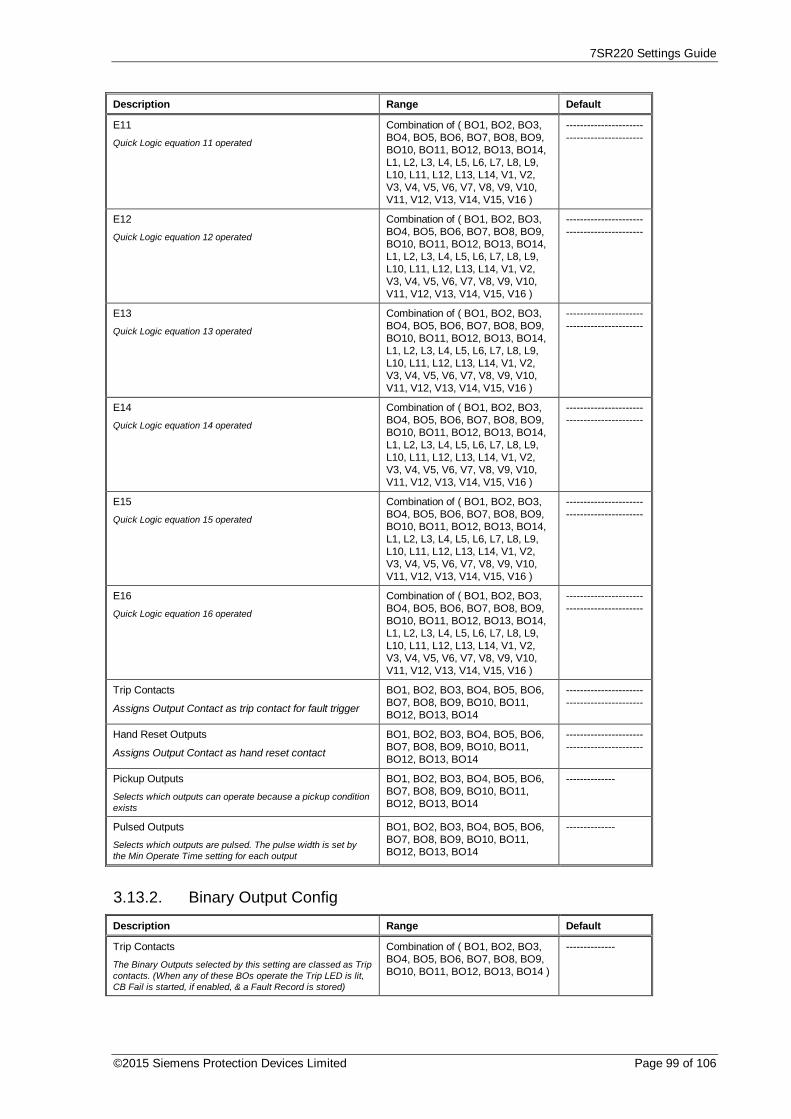
7SR220 Settings Guide
©2015 Siemens Protection Devices Limited Page 99 of 106
Description Range Default
E11
Quick Logic equation 11 operated
Combination of ( BO1, BO2, BO3,BO4, BO5, BO6, BO7, BO8, BO9,BO10, BO11, BO12, BO13, BO14,L1, L2, L3, L4, L5, L6, L7, L8, L9,L10, L11, L12, L13, L14, V1, V2,V3, V4, V5, V6, V7, V8, V9, V10,V11, V12, V13, V14, V15, V16 )
--------------------------------------------
E12
Quick Logic equation 12 operated
Combination of ( BO1, BO2, BO3,BO4, BO5, BO6, BO7, BO8, BO9,BO10, BO11, BO12, BO13, BO14,L1, L2, L3, L4, L5, L6, L7, L8, L9,L10, L11, L12, L13, L14, V1, V2,V3, V4, V5, V6, V7, V8, V9, V10,V11, V12, V13, V14, V15, V16 )
--------------------------------------------
E13
Quick Logic equation 13 operated
Combination of ( BO1, BO2, BO3,BO4, BO5, BO6, BO7, BO8, BO9,BO10, BO11, BO12, BO13, BO14,L1, L2, L3, L4, L5, L6, L7, L8, L9,L10, L11, L12, L13, L14, V1, V2,V3, V4, V5, V6, V7, V8, V9, V10,V11, V12, V13, V14, V15, V16 )
--------------------------------------------
E14
Quick Logic equation 14 operated
Combination of ( BO1, BO2, BO3,BO4, BO5, BO6, BO7, BO8, BO9,BO10, BO11, BO12, BO13, BO14,L1, L2, L3, L4, L5, L6, L7, L8, L9,L10, L11, L12, L13, L14, V1, V2,V3, V4, V5, V6, V7, V8, V9, V10,V11, V12, V13, V14, V15, V16 )
--------------------------------------------
E15
Quick Logic equation 15 operated
Combination of ( BO1, BO2, BO3,BO4, BO5, BO6, BO7, BO8, BO9,BO10, BO11, BO12, BO13, BO14,L1, L2, L3, L4, L5, L6, L7, L8, L9,L10, L11, L12, L13, L14, V1, V2,V3, V4, V5, V6, V7, V8, V9, V10,V11, V12, V13, V14, V15, V16 )
--------------------------------------------
E16
Quick Logic equation 16 operated
Combination of ( BO1, BO2, BO3,BO4, BO5, BO6, BO7, BO8, BO9,BO10, BO11, BO12, BO13, BO14,L1, L2, L3, L4, L5, L6, L7, L8, L9,L10, L11, L12, L13, L14, V1, V2,V3, V4, V5, V6, V7, V8, V9, V10,V11, V12, V13, V14, V15, V16 )
--------------------------------------------
Trip Contacts
Assigns Output Contact as trip contact for fault trigger
BO1, BO2, BO3, BO4, BO5, BO6,BO7, BO8, BO9, BO10, BO11,BO12, BO13, BO14
--------------------------------------------
Hand Reset Outputs
Assigns Output Contact as hand reset contact
BO1, BO2, BO3, BO4, BO5, BO6,BO7, BO8, BO9, BO10, BO11,BO12, BO13, BO14
--------------------------------------------
Pickup Outputs
Selects which outputs can operate because a pickup conditionexists
BO1, BO2, BO3, BO4, BO5, BO6,BO7, BO8, BO9, BO10, BO11,BO12, BO13, BO14
--------------
Pulsed Outputs
Selects which outputs are pulsed. The pulse width is set bythe Min Operate Time setting for each output
BO1, BO2, BO3, BO4, BO5, BO6,BO7, BO8, BO9, BO10, BO11,BO12, BO13, BO14
--------------
3.13.2. Binary Output Config
Description Range Default
Trip Contacts
The Binary Outputs selected by this setting are classed as Tripcontacts. (When any of these BOs operate the Trip LED is lit,CB Fail is started, if enabled, & a Fault Record is stored)
Combination of ( BO1, BO2, BO3,BO4, BO5, BO6, BO7, BO8, BO9,BO10, BO11, BO12, BO13, BO14 )
--------------

7SR220 Settings Guide
Page 100 of 106 © 2013 Siemens Protection Devices Limited
Description Range Default
Hand Reset Outputs
Relays selected, as Hand Reset will remain latched untilmanually reset from front panel or via communications link orby removing DC Supply. By default relays are Self Resettingand will reset when the driving signal is removed.
Combination of ( 1, 2, 3, 4, 5, 6, 7,8, 9, 10, 11, 12, 13, 14 )
--------------
Min Operate Time 1
Minimum operate time of output relay if set to self reset, if alsoset to be pulsed then this is the pulse width
0, 0.01 ... 59, 60 0.1 s
Min Operate Time 2
Minimum operate time of output relay 2 if set to self reset, ifalso set to be pulsed then this is the pulse width
0, 0.01 ... 59, 60 0.1 s
Min Operate Time 3
Minimum operate time of output relay 3 if set to self reset, ifalso set to be pulsed then this is the pulse width
0, 0.01 ... 59, 60 0.1 s
Min Operate Time 4
Minimum operate time of output relay 4 if set to self reset, ifalso set to be pulsed then this is the pulse width
0, 0.01 ... 59, 60 0.1 s
Min Operate Time 5
Minimum operate time of output relay 5 if set to self reset, ifalso set to be pulsed then this is the pulse width
0, 0.01 ... 59, 60 0.1 s
Min Operate Time 6
Minimum operate time of output relay 6 if set to self reset, ifalso set to be pulsed then this is the pulse width
0, 0.01 ... 59, 60 0 s
Min Operate Time 7
Minimum operate time of output relay 7 if set to self reset, ifalso set to be pulsed then this is the pulse width
0, 0.01 ... 59, 60 0 s
Min Operate Time 8
Minimum operate time of output relay 8 if set to self reset, ifalso set to be pulsed then this is the pulse width
0, 0.01 ... 59, 60 0 s
Min Operate Time 9
Minimum operate time of output relay 9 if set to self reset, ifalso set to be pulsed then this is the pulse width
0, 0.01 ... 59, 60 0 s
Min Operate Time 10
Minimum operate time of output relay 10 if set to self reset, ifalso set to be pulsed then this is the pulse width
0, 0.01 ... 59, 60 0.1 s
Min Operate Time 11
Minimum operate time of output relay 11 if set to self reset, ifalso set to be pulsed then this is the pulse width
0, 0.01 ... 59, 60 0.1 s
Min Operate Time 12
Minimum operate time of output relay 12 if set to self reset, ifalso set to be pulsed then this is the pulse width
0, 0.01 ... 59, 60 0.1 s
Min Operate Time 13
Minimum operate time of output relay 13 if set to self reset, ifalso set to be pulsed then this is the pulse width
0, 0.01 ... 59, 60 0.1 s
Min Operate Time 14
Minimum operate time of output relay 14 if set to self reset, ifalso set to be pulsed then this is the pulse width
0, 0.01 ... 59, 60 0.1 s
Pickup Outputs
Selects which outputs can operate because a pickup conditionexists
Combination of ( 1, 2, 3, 4, 5, 6, 7,8, 9, 10, 11, 12, 13, 14 )
--------------
Pulsed Outputs
Selects which outputs are pulsed. The pulse width is set bythe Min Operate Time setting for each output
Combination of ( 1, 2, 3, 4, 5, 6, 7,8, 9, 10, 11, 12, 13, 14 )
--------------
3.13.3. LED Config
Description Range Default

7SR220 Settings Guide
©2015 Siemens Protection Devices Limited Page 101 of 106
Description Range Default
Self Reset LEDs
LEDs selected, as Self Reset will automatically reset when thedriving signal is removed. By default all LEDs are Hand Resetand must be manually reset either locally via the front fascia orremotely via communications.
Combination of ( 1, 2, 3, 4, 5, 6, 7,8, 9, 10, 11, 12, 13, 14 )
1, 9, 10, 11, 12,13, 14
PU Self Reset LEDs
LEDs selected, as Self Reset will automatically reset when thedriving signal is removed. By default all PU LEDs are SelfReset.
Combination of ( 1, 2, 3, 4, 5, 6, 7,8, 9, 10, 11, 12, 13, 14 )
1, 2, 3, 4, 5, 6, 7,8, 9, 10, 11, 12,13, 14
Green LEDs
Selects which LEDs will be green when driven
Combination of ( 1, 2, 3, 4, 5, 6, 7,8, 9, 10, 11, 12, 13, 14 )
--------------
Red LEDs
Selects which LEDs will be red when driven
Combination of ( 1, 2, 3, 4, 5, 6, 7,8, 9, 10, 11, 12, 13, 14 )
1, 2, 3, 4, 5, 6, 7,8, 9, 10, 11, 12,13, 14
PU Green LEDs
Selects which LEDs will be green when driven by a pickup
Combination of ( 1, 2, 3, 4, 5, 6, 7,8, 9, 10, 11, 12, 13, 14 )
1, 2, 3, 4, 5, 6, 7,8, 9, 10, 11, 12,13, 14
PU Red LEDs
Selects which LEDs will be red when driven by a pickup
Combination of ( 1, 2, 3, 4, 5, 6, 7,8, 9, 10, 11, 12, 13, 14 )
1, 2, 3, 4, 5, 6, 7,8, 9, 10, 11, 12,13, 14
3.13.4. Pickup Config
Description Range Default
Gn P/F Pickups
When any of the selected pickups operate General Pickup isdriven.
Combination of ( 51-1, 51-2, 51-3,51-4, 50-1, 50-2, 50-3, 50-4 )
51-1, 51-2, 51-3,51-4, 50-1, 50-2,50-3, 50-4
Gn E/F Pickups
As Above
Combination of ( 51N-1, 51N-2,51N-3, 51N-4, 50N-1, 50N-2, 50N-3, 50N-4, 51G-1, 51G-2, 51G-3,51G-4, 50G-1, 50G-2, 50G-3, 50G-4 )
51N-1, 51N-2,51N-3, 51N-4,50N-1, 50N-2,50N-3, 50N-4,51G-1, 51G-2,51G-3, 51G-4,50G-1, 50G-2,50G-3, 50G-4
Gn SEF/REF Pickups
As Above
Combination of ( 51SEF-1, 51SEF-2, 51SEF-3, 51SEF-4, 50SEF-1,50SEF-2, 50SEF-3, 50SEF-4, 64H)
51SEF-1,51SEF-2,51SEF-3,51SEF-4,50SEF-1,50SEF-2,50SEF-3,50SEF-4, 64H
Gn Voltage Pickups
As Above
Combination of ( 27/59-1, 27/59-2,27/59-3, 27/59-4, Vx 27/59, 47-1,47-2, 59NIT, 59NDT )
27/59-1, 27/59-2,27/59-3, 27/59-4,Vx 27/59, 47-1,47-2, 59NIT,59NDT
Gn Freq Pickups
As Above
Combination of ( 81-1, 81-2, 81-3,81-4, 81-5, 81-6 )
81-1, 81-2, 81-3,81-4, 81-5, 81-6
Gn Misc Pickups
As Above
Combination of ( 46IT, 46DT, 37-1,37-2, 37G-1, 37G-2, 37SEF-1,37SEF-2 )
46IT, 46DT, 37-1, 37-2, 37G-1,37G-2, 37SEF-1,37SEF-2
3.14. Maintenance

7SR220 Settings Guide
Page 102 of 106 © 2013 Siemens Protection Devices Limited
3.14.1. CB Counters
Description Range Default
Gn CB Total Trip Count
Selects whether the CB Total Trip Count counter is enabled
Disabled, Enabled Disabled
Gn CB Total Trip Count Target
Selects the number of CB trips allowed before CB Total TripCount counter output operates
0, 1 ... 9999, 10000 100
Gn CB Total Trip Count Reset
Resets CB Total Trip Count counter
Gn CB Total Trip Manual Open
Selects whether the CB Total Trip Manual Open is enabled
Disabled, Enabled Disabled
Gn CB Phase Trip Counters
Selects whether the CB Phase Trip Counters is enabled
Disabled, Enabled Disabled
Gn CB Ph A Trip Count Target
Selects the number of CB trips allowed before CB Ph A TripCount counter output operates
0, 1 ... 9999, 10000 100
Gn CB Ph B Trip Count Target
Selects the number of CB trips allowed before CB Ph B TripCount counter output operates
0, 1 ... 9999, 10000 100
Gn CB Ph C Trip Count Target
Selects the number of CB trips allowed before CB Ph C TripCount counter output operates
0, 1 ... 9999, 10000 100
Gn CB E/F Trip Count Target
Selects the number of CB trips allowed before CB E/F TripCount counter output operates
0, 1 ... 9999, 10000 100
Gn CB Delta Trip Count
Selects whether the CB Delta Trip Count counter is enabled
Disabled, Enabled Disabled
Gn CB Delta Trip Count Target
Selects the number of CB trips allowed before CB Delta TripCount counter output operates
0, 1 ... 9999, 10000 100
Gn CB Delta Trip Count Reset
Resets CB Delta Trip Count counter
Gn CB Count To AR Block
Selects whether the CB Count To AR Block counter is enabled
Disabled, Enabled Disabled
Gn CB Count To AR Block Target
Selects the number of CB trips allowed before CB Count ToAR Block counter output operates. While count is above targetthe Autorecloser will only perform 1 x Delayed Shot andLockout
0, 1 ... 9999, 10000 100
Gn CB Count To AR Block Reset
Resets CB Count To AR Block counter
Gn CB Freq Ops Count
Selects whether the CB Frequent Operations Counter isenabled
Disabled, Enabled Disabled
Gn CB Freq Ops Count Target
Selects the number of CB trips allowed before CB FrequentOperations Counter output operates. While count is abovetarget the Autorecloser will only perform 1 x Delayed Shot andLockout
0, 1 ... 9999, 10000 10
Gn CB Freq Ops Count Reset
Resets CB Frequent Operations Counter
3.14.2. I^2T CB Wear
Description Range Default

7SR220 Settings Guide
©2015 Siemens Protection Devices Limited Page 103 of 106
Description Range Default
Gn I^2t Counter
Selects whether the I^2t CB Wear monitor is enabled
Disabled, Enabled Disabled
Gn Alarm Limit
Sets limit before alarm is issued
10, 11 ... 99000, 100000 10 MA^2 s
Gn Separation Time
Sets the time for CB mechanism to start moving, time beforecontacts start to separate
0, 0.001 ... 0.199, 0.2 0.02 s
Gn Clearance Time
Time for CB to clear fault
0, 0.001 ... 0.199, 0.2 0.04 s
Reset I^2t Count
Reset the CB wear count
3.14.3. START COUNT
Description Range Default
Start Types(s)
Selects which type of start-up
Power On, Expected, Unexpected All
Start Count Target
Selects number of times star-up has occurred before outputoperatest
0, ...10000 100
3.15. Data Storage3.15.1. Demand Data/Log
Description Range Default
Data Log Period
Selects period between stored samples
5, 6, 7, 8, 9, 10, 15, 20, 25, 30, 35,40, 45, 50, 55, 60
5 min
Clear Data Log
Clear the Data Log
Gn Demand Window
The time window over which the Min, Max and Mean valuesare calculated.
1, 2 ... 23, 24 24 hrs
Gn Demand Window Type
Method used to calculate Demand values.
Fixed, Peak, Rolling Fixed
Gn Demand Reset
Reset all Demand values
3.15.2. Waveform Storage
Description Range Default
Gn P/F Trig Storage
Select which elements trigger a waveform record
Combination of ( 51-1, 51-2, 51-3,51-4, 50-1, 50-2, 50-3, 50-4 )
51-1, 51-2, 51-3,51-4, 50-1, 50-2,50-3, 50-4
Gn E/F Trig Storage
As Above
Combination of ( 51N-1, 51N-2,51N-3, 51N-4, 50N-1, 50N-2, 50N-3, 50N-4, 51G-1, 51G-2, 51G-3,51G-4, 50G-1, 50G-2, 50G-3, 50G-4 )
51N-1, 51N-2,51N-3, 51N-4,50N-1, 50N-2,50N-3, 50N-4,51G-1, 51G-2,51G-3, 51G-4,50G-1, 50G-2,50G-3, 50G-4

7SR220 Settings Guide
Page 104 of 106 © 2013 Siemens Protection Devices Limited
Description Range Default
Gn SEF/REF Trig Storage
As Above
Combination of ( 51SEF-1, 51SEF-2, 51SEF-3, 51SEF-4, 50SEF-1,50SEF-2, 50SEF-3, 50SEF-4, 64H)
51SEF-1,51SEF-2,51SEF-3,51SEF-4,50SEF-1,50SEF-2,50SEF-3,50SEF-4, 64H
Gn Misc Current Storage
As Above
Combination of ( 46IT, 46DT, 37-1,37-2, 49 Trip, 49 Alarm, 37G-1,37G-2, 37SEF-1, 37SEF-2 )
----------
Gn Voltage Trig Storage
As Above
Combination of ( 27/59-1, 27/59-2,27/59-3, 27/59-4, Vx 27/59, 47-1,47-2, 59NIT, 59NDT )
---------
Gn Freq Trig Storage
As Above
Combination of ( 81-1, 81-2, 81-3,81-4, 81-5, 81-6 )
------
Gn AFD Trig Storage
As Above
Combination of ( AFD-1, AFD-2,AFD-3, AFD-4, AFD-5, AFD-6)
------
Pre-trigger Storage
Select Percentage of waveform record stored before the faultis triggered
10, 20, 30, 40, 50, 60, 70, 80, 90 20 %
Record Duration
Select waveform record duration
10 Rec x 1 Sec, 5 Rec x 2 Sec, 2Rec x 5 Sec, 1 Rec x 10 Sec
10 Rec x 1 Sec
Trigger Waveform
Trigger waveform storage
Clear Waveforms
Clear all stored waveform records
3.15.3. Fault Storage
Description Range Default
Gn Max Fault Rec Time
Maximum time Fault record information will be stored andclassed as same fault
0, 1 ... 59900, 60000 2000 ms
Clear Faults
Clear all stored fault records
3.15.4. Event Storage
Description Range Default
Clear Events
Clear all stored event records
3.15.5. Energy Storage
Description Range Default
Gn Active Exp Energy Unit 1kWh, 10kWh, 100kWh, 1MWh,10MWh, 100MWh
10 kWh
Gn Active Imp Energy Unit 1kWh, 10kWh, 100kWh, 1MWh,10MWh, 100MWh
10 kWh
Gn Reactive Exp Energy Unit 1kVArh, 10kVArh, 100kVArh,1MVArh, 10MVArh, 100MVArh
10 kVArh

7SR220 Settings Guide
©2015 Siemens Protection Devices Limited Page 105 of 106
Description Range Default
Gn Reactive Imp Energy Unit 1kVArh, 10kVArh, 100kVArh,1MVArh, 10MVArh, 100MVArh
10 kVArh
Data Log
Selects whether the Data Logger is enabled
3.15.6. Fault Locator
Description Range Default
Fault Locator Disabled, Enabled Disabled
Line Angle 0 Deg to 90 Deg 75 Deg
EF Comp Z0/Z1 Ratio 0 to 10 2.5
EF Comp Z0 Angle 0 Deg to 359 Deg 75 Deg
Z+ Impedance 0.1 Ohms to 250 Ohms 10 Ohms
Sec’y Z+ Per Unit Distance 0.005 Ohms to 5 Ohms 0.5 Ohm
Display Units Percent, kilometres, miles Percent
System Earthing Normal, Compensated Normal
Gn U0/U1 Ratio 0 to 1 0.1
Gn Freq FL Inhibits 6 Bit Binary 81-1, 81-2, 81-3,81-4, 81-5, 81-6
Gn Freq FL Inhibits 13 Bit Binary 49, 46IT, 46DT,27/59-1, 27/59-2,27/59-3, 27/59-4,47-1, 47-2,59NIT, 59NDT,46BC, Vx 27/59
3.15.7. Communications
Description Range Default
Station Address
IEC 60870-5-103 Station Address
0, 1 ... 65533, 65534 1
COM1-RS485 Protocol
Selects protocol to use for COM1-RS485
OFF, IEC60870-5-103, MODBUS-RTU, DNP3
IEC60870-5-103
COM1-RS485 Baud Rate
Sets the communications baud rate for COM1-RS485
75, 110, 150, 300, 600, 1200, 2400,4800, 9600, 19200, 38400
19200
COM1-RS485 Parity
Selects whether parity information is used
NONE, ODD, EVEN EVEN
COM1-RS485 Mode Local, Remote, Local Or Remote Remote
COM2-USB Protocol
Selects protocol to use for COM2-USB
IEC60870-5-103 IEC60870-5-103
COM2-USB Mode Local Local
COM3 Protocol
Selects protocol to use for COM3
OFF, IEC60870-5-103, MODBUS-RTU, DNP3
IEC60870-5-103
COM3 Baud Rate
Sets the communications baud rate for COM3
75, 110, 150, 300, 600, 1200, 2400,4800, 9600, 19200, 38400, 57600,115200
19200
COM3 Parity
Selects whether parity information is used
NONE, ODD, EVEN EVEN

7SR220 Settings Guide
Page 106 of 106 © 2013 Siemens Protection Devices Limited
Description Range Default
COM3 Line Idle
Selects the communications line idle sense
LIGHT OFF, LIGHT ON LIGHT OFF
COM3 Data Echo
Enables echoing of data from RX port to TX port whenoperating relays in a Fibre Optic ring configuration
OFF, ON OFF
COM3 Mode Local, Remote, Local Or Remote Remote
COM4 Protocol
Selects protocol to use for COM4
OFF, IEC60870-5-103, MODBUS-RTU, DNP3
OFF
COM4 Baud Rate
Sets the communications baud rate for COM4
75, 110, 150, 300, 600, 1200, 2400,4800, 9600, 19200, 38400
19200
COM4 Parity
Selects whether parity information is used
NONE, ODD, EVEN EVEN
COM4 Line Idle
Selects the communications line idle sense
LIGHT OFF, LIGHT ON LIGHT OFF
COM4 Data Echo
Enables echoing of data from RX port to TX port whenoperating relays in a Fibre Optic ring configuration
OFF, ON OFF
COM4 Mode Local, Remote, Local Or Remote Remote
LAN Protocol
Selects protocol to use for LAN port
OFF, IEC60870-5-103 IEC60870-5-103
DNP3 Unsolicited Events
Allows unsolicited event support in the relay. When Enabled,unsolicited event transmission can be controlled by theMaster. When Disabled, Master requests are ignored.
Disabled, Enabled Disabled
DNP3 Destination Address
The address of the master to which unsolicited events will besent.
0, 1 ... 65533, 65534 0
DNP3 Application Timeout
The address of the master to which unsolicited events will besent.
5, 6 ... 299, 300 10 s

The copyright and other intellectual property rights in this document, and in any model or article produced fromit (and including any registered or unregistered design rights) are the property of Siemens Protection DevicesLimited. No part of this document shall be reproduced or modified or stored in another form, in any dataretrieval system, without the permission of Siemens Protection Devices Limited, nor shall any model or articlebe reproduced from this document unless Siemens Protection Devices Limited consent.
While the information and guidance given in this document is believed to be correct, no liability shall beaccepted for any loss or damage caused by any error or omission, whether such error or omission is the resultof negligence or any other cause. Any and all such liability is disclaimed.
© 2014 Siemens Protection Devices Limited
7SR220 Directional Relay
Instrumentation Guide

7SR220 Instrumentation Guide
Page 2 of 15 © 2014 Siemens Protection Devices Limited
Document Release History
This document is issue 2015/06
2011/05 First issue
2013/01 Typographical revisions and added data. Updated in line with software release.
2014/06 Typographical revisions and added data. Updated in line with software release.
2015/06 Typographical revisions and added data. Updated in line with software release.
Software Revision History2011/05 2435H85009R7a-7a (7SR220) First Release
2013/01 2435H85009R7c-7b (7SR220) Introduced journaling file system.Added 61850 logical nodes for CB Counters, metering, 50BF,46BC, 81HBL2 and line check.Added Line Check on non-AR devices.Added 74CCS Close Circuit Supervision.
2014/06 2435H85009R7f-7d (7SR220) Added Fault Locator feature and Check Sync feature.Fault data transmitted over 103.Additional communications data, control features, meters.
2015/06 2435H85009R8a-7f (7SR220) Added Power Factor Meters, Load Blinding feature, Arc FlashDetector. Over current TM Setting Range extended.

7SR220 Instrumentation Guide
© 2014 Siemens Protection Devices Limited Page 3 of 15
Contents
Document Release History .............................................................................................................. 2
Software Revision History ............................................................................................................... 2
1. Function Diagram .................................................................................................................... 4
2. Menu Structure ........................................................................................................................ 5
1. Relay Instrumentation ............................................................................................................. 61.1. Favourite Meters............................................................................................................. 61.2. Current Meters ................................................................................................................ 61.3. Voltage Meters ................................................................................................................ 81.4. Frequency Meters .......................................................................................................... 81.5. Power Meters .................................................................................................................. 91.6. Energy Meters............................................................................................................... 101.7. Directional Meters ........................................................................................................ 101.8. Thermal Meters ............................................................................................................. 101.9. Auto-Reclose Meters.................................................................................................... 111.10.Maintenance Meters ..................................................................................................... 111.11.Genera Alarm Meters ................................................................................................... 111.12.Demand Meters ............................................................................................................ 121.13.Binary Input Meters ...................................................................................................... 131.14.Binary Output Meters ................................................................................................... 131.15.Virtual Meters ................................................................................................................ 131.16.Communication Meters ................................................................................................ 141.17.Miscellaneous Meters .................................................................................................. 141.18.Quick Logic Meters ...................................................................................................... 151.19.Fault Locator ................................................................................................................. 15

7SR220 Instrumentation Guide
Page 4 of 15 © 2014 Siemens Protection Devices Limited
1.Function Diagram

7SR220 Instrumentation Guide
© 2014 Siemens Protection Devices Limited Page 5 of 15
2.Menu Structure

7SR220 Instrumentation Guide
Page 6 of 15 © 2014 Siemens Protection Devices Limited
1. Relay Instrumentation
1.1. Favourite Meters
Instrument Description
--------------------FAVOURITE METERS > to view
This allows the user to view his previously constructed list of ‘favourite meters’by pressing TEST/RESET button and the READ DOWN button to scrollthough the meters added to this sub-group
To construct a sub-group of favourite meters, first go to the desired meter thenpress ENTER this will cause a message to appear on the LCD ‘Add ToFavourites YES pressing ENTER again will add this to the FAVOURITEMETERS Sub-menu. To remove a meter from the FAVOURITE METERS sub-menu go to that meter each in the FAVOURITE METERS sub-menu or at itsPrimary location press ENTER and the message ‘Remove From Favourites’ willappear press ENTER again and this meter will be removed from theFAVOURITE METERS sub-group
1.2. Current Meters
Instrument Description
--------------------CURRENT METERS > to view--------------------
This is the sub-group that includes all the meters that are associated withCurrent TEST/RESET allows access to this sub-group
Primary CurrentIa 0.00AIb 0.00AIc 0.00A
Displays the 3 phase currents Primary RMS values
Secondary CurrentIa 0.00AIb 0.00AIc 0.00A
Displays the 3 phase currents Secondary RMS values
Nom CurrentIa 0.00xIn ----o
Ib 0.00xIn ----o
Ic 0.00xIn ----o
Displays the 3 phase currents Nominal RMS values & phase angles withrespect to PPS current.
Pri Earth CurrentIn 0.000AIg 0.000A
Displays the 3 Earth currents Primary RMS values
Sec Earth CurrentIn 0.000AIg 0.000A
Displays the 3 Earth currents Secondary RMS values
Nom Earth CurrentIn 0.000xIn ----o
Ig 0.000xIn ----o
Displays the 3 Earth currents Nominal RMS values & phase angles with respectto PPS current.
I Seq ComponentsIzps 0.00xIn ----o
Ipps 0.00xIn ----o
Inps 0.00xIn ----o
Displays the Current Sequence components Nominal RMS values & phaseangles with respect to PPS current.
2nd Harmonic CurrentIa 0.00xInIb 0.00xIn
Displays the 3 phase currents 2nd Harmonic components Nominal RMS values.

7SR220 Instrumentation Guide
© 2014 Siemens Protection Devices Limited Page 7 of 15
Instrument DescriptionIc 0.00xIn

7SR220 Instrumentation Guide
Page 8 of 15 © 2014 Siemens Protection Devices Limited
1.3. Voltage Meters--------------------VOLTAGE METERS > to view--------------------
This is the sub-group that includes all the meters that are associated withVoltage TEST/RESET allows access to this sub-group
Prim Ph-Ph VoltageVab 0.00VVbc 0.00VVca 0.00V
Displays the Phase to Phase Voltage Primary RMS values
Sec Ph-Ph VoltageVab 0.00VVbc 0.00VVca 0.00V
Displays the Phase to Phase Voltage Secondary RMS values & Angles withrespect to PPS voltage.
Nominal Ph-Ph VoltageVab 0.00xVn ----oVbc 0.00xVn ----oVca 0.00xVn ----o
Displays the Phase to Phase Voltage Nominal RMS values
Prim Ph-N VoltageVa 0.00VVb 0.00VVc 0.00V
Displays the Phase to Neutral Voltage Primary RMS values
Sec Ph-N VoltageVa 0.00VVb 0.00VVc 0.00V
Displays the Phase to Neutral Voltage Secondary RMS values & Angles withrespect to PPS voltage.
Nom Ph-N VoltageVa 0.00xVn ----oVb 0.00xVn ----oVc 0.00xVn ----o
Displays the Phase to Neutral Voltage Nominal RMS values
V Seq ComponentsIzps 0.00V ----oIpps 0.00V ----oInps 0.00V ----o
Displays the Voltage Sequence components Nominal RMS values & phaseangles with respect to PPS voltage.
Calc Earth VoltagePri 0.00VSec 0.00V ----o
Displays the calculated Earth voltage both primary and secondary which alsoshows the secondary angle
CS/NVD Voltage (Vx)Pri 0.00VSec 0.00V ----o
Displays the 4th voltage (Vx) both primary and secondary which also showsthe secondary angle. This voltage can be used for NVD, Vx 27/59 or whereavailable Checksync.
1.4. Frequency Meters
Instrument Description
--------------------FREQUENCY METERS > to view--------------------
This is the sub-group that includes all the meters that are associated withFrequency TEST/RESET allows access to this sub-group
Frequency 0.000HzDisplays the power system frequency.

7SR220 Instrumentation Guide
© 2014 Siemens Protection Devices Limited Page 9 of 15
1.5. Power Meters
Instrument Description--------------------POWER METERS > to view--------------------
This is the sub-group that includes all the meters that are associated withPower TEST/RESET allows access to this sub-group
Primary (P)Phase A 0.0WPhase B 0.0WPhase C 0.0W
Displays Primary Real Power
Secondary (P)Phase A 0.0WPhase B 0.0WPhase C 0.0W
Displays Secondary Real Power
Primary (Q)Phase A 0.0VArPhase B 0.0VArPhase C 0.0VAr
Displays Primary Reactive Power
Secondary (Q)Phase A 0.0VArPhase B 0.0VArPhase C 0.0VAr
Displays Secondary Reactive Power
Primary (S)Phase A 0.0VAPhase B 0.0VAPhase C 0.0VA
Displays Primary Apparent Power
Secondary (S)Phase A 0.0VArPhase B 0.0VArPhase C 0.0VAr
Displays Secondary Apparent Power
Primary (3P)P 0.0WQ 0.0VArS 0.0VA
Displays 3-Phase Primary Power
Secondary (3P)P 0.0WQ 0.0VArS 0.0VA
Displays 3-Phase Secondary Power
PF A 0.00PF B 0.00PF C 0.00PF (3P) 0.00
Displays Power factor

7SR220 Instrumentation Guide
Page 10 of 15 © 2014 Siemens Protection Devices Limited
1.6. Energy Meters
Instrument Description--------------------ENERGY METERS > to view--------------------
This is the sub-group that includes all the meters that are associated withEnergy TEST/RESET allows access to this sub-group
Active EnergyExp 000000x10kWhImp 000000x10kWh
Displays both imported and exported Active Energy
Reactive EnergyExp 000000x10kVArhImp 000000x10kVArh
Displays both imported and exported Reactive Energy
1.7. Directional Meters
Instrument Description--------------------DIRECTIONAL METERS > to view--------------------
This is the sub-group that includes all the meters that are associated withDirectional elements TEST/RESET allows access to this sub-group. Onlyseen on models that have the 67 option
P/F Dir (67)--------------------
No Dir
The appropriate values from the selection will be displayed.
No Dir, PhA Fwd, PhA Rev, PhB Fwd, PhB Rev, PhC Fwd, PhC Rev
Calc E/F Dir (67N)--------------------
No Dir
The appropriate values from the selection will be displayed.
No Dir, E/F Fwd, E/F Rev
Meas E/F Dir (67G)--------------------
No Dir
The appropriate values from the selection will be displayed.
No Dir, E/F Fwd, E/F Rev
SEF Dir (67SEF)--------------------
No Dir
The appropriate values from the selection will be displayed.
No Dir, SEF Fwd, SEF Rev
1.8. Thermal Meters
Instrument Description
--------------------THERMAL METERS > to view
This is the sub-group that includes all the meters that are associated withThermal TEST/RESET allows access to this sub-group
Thermal StatusPhase A 0.0%Phase B 0.0%Phase C 0.0%
Displays the thermal capacity

7SR220 Instrumentation Guide
© 2014 Siemens Protection Devices Limited Page 11 of 15
1.9. Auto-Reclose Meters
Instrument Description
--------------------AUTORECLOSE METERS > to view--------------------
This is the sub-group that includes all the meters that are associated withAutoreclose TEST/RESET allows access to this sub-group. Only seen onmodels that have the 79 option
Autoreclose StatusOut Of ServiceClose Shot 0
Status of the autoreclose.
1.10. Maintenance Meters
Instrument Description
--------------------MAINTENANCE METERS > to view--------------------
This is the sub-group that includes all the meters that are associated withMaintenance TEST/RESET allows access to this sub-group
CB Total TripsCount 0Target 100
Displays the number of CB trips experienced by the CB
CB Delta TripsCount 0Target 100
Displays the number of CB trips experienced by the CB
CB Count To AR BlockCount 0Target 100
Displays the number of CB trips experienced by the CB. When the target isreached the relay will only do 1 Delayed Trip to Lockout.
CB Freq Ops CountCount 0Target 10
Displays the number of CB trips experienced by the CB over the last rolling 1 hrperiod. When the target is reached the relay will only do 1 Delayed Trip toLockout.
CB WearPhase A 0.00MA^2sPhase B 0.00MA^2sPhase C 0.00MA^2s
Displays the current measure of circuit breaker wear.
CB Trip Time0.0ms
Displays the trip time for the circuit breaker.
1.11. Genera Alarm Meters
Instrument Description
--------------------GENERAL ALARMMETERS > to view--------------------
This is the sub-group that includes all the meters that are associated with theBinary inputs TEST/RESET allows access to this sub-group
General Alarms--------------------ALARM 1 Cleared
Displays the state of General Alarm
…

7SR220 Instrumentation Guide
Page 12 of 15 © 2014 Siemens Protection Devices Limited
Instrument DescriptionGeneral Alarms--------------------ALARM 20 Cleared
1.12. Demand Meters
Instrument Description
--------------------DEMAND METERS > to view--------------------
This is the sub-group that includes all the meters that are associated with thedemand metering. TEST/RESET allows access to this sub-group
V Phase A DemandMax 0.00VMin 0.00VMean 0.00V
Shows the Max, Min and Mean Voltage for Phase A.
V Phase B DemandMax 0.00VMin 0.00VMean 0.00V
Shows the Max, Min and Mean Voltage for Phase AB.
V Phase C DemandMax 0.00VMin 0.00VMean 0.00V
Shows the Max, Min and Mean Voltage for Phase AC.
V Phase AB DemandMax 0.00VMin 0.00VMean 0.00V
Shows the Max, Min and Mean Voltage for Phase AB.
V Phase BC DemandMax 0.00VMin 0.00VMean 0.00V
Shows the Max, Min and Mean Voltage for Phase BC.
V Phase CA DemandMax 0.00VMin 0.00VMean 0.00V
Shows the Max, Min and Mean Voltage for Phase CA.
I Phase A DemandMax 0.00AMin 0.00AMean 0.00A
Shows the Max, Min and Mean for Phase A.
I Phase B DemandMax 0.00AMin 0.00AMean 0.00A
Shows the Max, Min and Mean for Phase B.
I Phase C DemandMax 0.00AMin 0.00AMean 0.00A
Shows the Max, Min and Mean for Phase C.
Power P 3P DemandMax 0.00WMin 0.00WMean 0.00W
Shows the Max, Min and Mean for Power P 3P Demand.
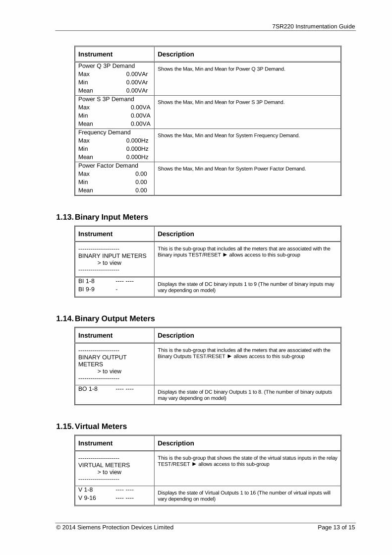
7SR220 Instrumentation Guide
© 2014 Siemens Protection Devices Limited Page 13 of 15
Instrument DescriptionPower Q 3P DemandMax 0.00VArMin 0.00VArMean 0.00VAr
Shows the Max, Min and Mean for Power Q 3P Demand.
Power S 3P DemandMax 0.00VAMin 0.00VAMean 0.00VA
Shows the Max, Min and Mean for Power S 3P Demand.
Frequency DemandMax 0.000HzMin 0.000HzMean 0.000Hz
Shows the Max, Min and Mean for System Frequency Demand.
Power Factor DemandMax 0.00Min 0.00Mean 0.00
Shows the Max, Min and Mean for System Power Factor Demand.
1.13. Binary Input Meters
Instrument Description
--------------------BINARY INPUT METERS > to view--------------------
This is the sub-group that includes all the meters that are associated with theBinary inputs TEST/RESET allows access to this sub-group
BI 1-8 ---- ----BI 9-9 -
Displays the state of DC binary inputs 1 to 9 (The number of binary inputs mayvary depending on model)
1.14. Binary Output Meters
Instrument Description
--------------------BINARY OUTPUTMETERS > to view--------------------
This is the sub-group that includes all the meters that are associated with theBinary Outputs TEST/RESET allows access to this sub-group
BO 1-8 ---- ---- Displays the state of DC binary Outputs 1 to 8. (The number of binary outputsmay vary depending on model)
1.15. Virtual Meters
Instrument Description
--------------------VIRTUAL METERS > to view--------------------
This is the sub-group that shows the state of the virtual status inputs in the relayTEST/RESET allows access to this sub-group
V 1-8 ---- ----V 9-16 ---- ----
Displays the state of Virtual Outputs 1 to 16 (The number of virtual inputs willvary depending on model)

7SR220 Instrumentation Guide
Page 14 of 15 © 2014 Siemens Protection Devices Limited
1.16. Communication Meters
Instrument Description
--------------------COMMUNICATIONMETERS > to view--------------------
This is the sub-group that includes all the meters that are associated withCommunications ports TEST/RESET allows access to this sub-group
COM1COM2COM3COM4
Displays which com ports are currently active
COM1 TRAFFICTx1 0Rx1 0Rx1 Errors 0
Displays traffic on Com1
COM2 TRAFFICTx2 0Rx2 0Rx2 Errors 0
Displays traffic on Com2
COM3 TRAFFICTx3 0Rx3 0Rx3 Errors 0
Displays traffic on Com3
COM4 TRAFFICTx4 0Rx4 0Rx4 Errors 0
Displays traffic on Com4
1.17. Miscellaneous Meters
Instrument Description
--------------------MISCELLANEOUSMETERS > to view--------------------
This is the sub-group that includes indication such as the relays time and date,the amount of fault and waveform records stored in the relay TEST/RESET allows access to this sub-group
Date 01/01/2000Time 22:41:44Waveform Recs 0Fault Recs 0
This meter displays the Date, Time, Waveform Records and the number ofFault Records stored in the relay
Event Recs 0Data Log Recs 0Settings Group 1
This meter displays the Event Records, Data Log Records and Active SettingsGroup number stored in the relay

7SR220 Instrumentation Guide
© 2014 Siemens Protection Devices Limited Page 15 of 15
1.18. Quick Logic Meters
Instrument Description
--------------------QUICK LOGIC METERS > to view--------------------
This is the sub-group that includes all the meters that are associated withQuickLogic. TEST/RESET allows access to this sub-group
E 1-8 ---- ----E 9-16 ---- ----
Shows the state of all the equations
E1 EquationEQN =0TMR 0-0 =0CNT 0-1 =0
Shows the state of an individual equation. EQN shows the equation state. TMRshows the timer progress and state for the equation. CNT shows the countprogress and state for the equation.
…E16 EquationEQN =0TMR 0-0 =0CNT 0-1 =0
Shows the state of an individual equation. EQN shows the equation state. TMRshows the timer progress and state for the equation. CNT shows the countprogress and state for the equation.
1.19. Fault Locator
Instrument Description
--------------------FAULT LOCATOR METER > to view--------------------
This is the sub-group that includes all the meters that are associated withthe Fault Locator TEST/RESET allows access to this sub-group
Distance 0.0%Impedance 0.0ohmsReactance 0.0ohms
Displays the Fault Location.

The copyright and other intellectual property rights in this document, and in any model or article produced from it(and including any registered or unregistered design rights) are the property of Siemens Protection DevicesLimited. No part of this document shall be reproduced or modified or stored in another form, in any data retrievalsystem, without the permission of Siemens Protection Devices Limited, nor shall any model or article bereproduced from this document unless Siemens Protection Devices Limited consent.
While the information and guidance given in this document is believed to be correct, no liability shall be acceptedfor any loss or damage caused by any error or omission, whether such error or omission is the result ofnegligence or any other cause. Any and all such liability is disclaimed.
© 2013 Siemens Protection Devices Limited
7SR210 Non-Directional Relay
7SR220 Directional Relay
Performance Specification

7SR210 & 7SR220 Performance Specification
Page 2 of 62 © 2013 Siemens Protection Devices Limited
Document Release HistoryThis document is issue 2015/06. The list of revisions up to and including this issue is: -
2011/05 First issue.
2011/08 Typographical revisions and added data.
2013/01 Typographical revisions and added data. Updated in line with software release.
2014/06 Typographical revisions and added data. Updated in line with software release.
2015/06 Typographical revisions and added data. Updated in line with software release.
Software Revision History2011/05 2435H85008R7a-7a (7SR210)
2435H85009R7a-7a (7SR220)
First Release
2013/01 2435H85008R7c-7b (7SR210)
2435H85009R7c-7b (7SR220)
Introduced journaling file system.Added 61850 logical nodes for CB Counters, metering, 50BF,46BC, 81HBL2 and line check.Added Line Check on non-AR devices.Added 74CCS Close Circuit Supervision.
2014/06 2435H85008R7f-7d (7SR210)
2435H85009R7f-7d (7SR220)
Added Fault Locator feature and Check Sync feature.Fault data transmitted over 103.Additional communications data, control features, meters.
2015/06 2435H85008R8a-7f (7SR210)
2435H85009R8a-7f (7SR220)
Added Power Factor Meters, Load Blinding feature, Arc FlashDetector. Over current TM Setting Range extended.

7SR21 & 7SR22 Performance Specification
© 2013 Siemens Protection Devices Limited Page 3 of 62
Contents
Software Revision History ................................................................................................................ 2Section 1: Common Functions ......................................................................................................... 7
1.1 General ................................................................................................................................ 71.1.1 CE Conformity ......................................................................................................... 71.1.2 Reference ................................................................................................................ 71.1.3 Dimensions .............................................................................................................. 71.1.4 Weights ................................................................................................................... 8
1.2 Energising Quantities ........................................................................................................... 91.2.1 Auxiliary Power Supply ............................................................................................ 91.2.2 AC Current............................................................................................................... 91.2.3 AC Voltage ............................................................................................................ 101.2.4 Binary (Digital) Outputs .......................................................................................... 111.2.5 Binary (Digital) Inputs ............................................................................................. 12
1.3 Functional Performance ..................................................................................................... 141.3.1 Instrumentation ...................................................................................................... 141.3.2 USB Data Communication Interface ....................................................................... 141.3.3 Fibre Optic Serial Data Communication Interface (Optional Rear Mounted Port) ..... 141.3.4 RS485 Data Communication Interface (Standard Rear Port) .................................. 141.3.5 RS485 Data Communication Interface (Optional Rear Mounted Port) ..................... 141.3.6 RS232 Data Communication Interface (Optional Rear Mounted Port) ..................... 141.3.7 Fibre Optic Ethernet Data Communication Interface (IEC 61850 Option) ................ 151.3.8 Electrical Ethernet Data Communication Interface (IEC 61850 Option) ................... 151.3.9 Real Time Clock .................................................................................................... 15
1.4 Environmental Performance ............................................................................................... 161.4.1 General.................................................................................................................. 161.4.2 Emissions .............................................................................................................. 171.4.3 Immunity ................................................................................................................ 171.4.4 Mechanical ............................................................................................................ 19
Section 2: Protection Functions ..................................................................................................... 202.1 27/59 Phase Under/Over Voltage ....................................................................................... 20
2.1.2 Reference .............................................................................................................. 202.1.3 Operate and Reset Level ....................................................................................... 202.1.4 Operate and Reset Time ........................................................................................ 20
2.2 27/59 Vx Under/Over Voltage ............................................................................................. 212.2.1 Reference .............................................................................................................. 212.2.2 Operate and Reset Level ....................................................................................... 212.2.3 Operate and Reset Time ........................................................................................ 21
2.3 37 Undercurrent ................................................................................................................. 222.3.1 Reference .............................................................................................................. 222.3.2 Operate and Reset Level ....................................................................................... 222.3.3 Operate and Reset Time ........................................................................................ 22
2.4 37G & 37SEF Undercurrent................................................................................................ 232.4.1 Reference .............................................................................................................. 232.4.2 Operate and Reset Level ....................................................................................... 232.4.3 Operate and Reset Time ........................................................................................ 23
2.5 46NPS Negative Phase Sequence Overcurrent .................................................................. 242.5.1 Reference (46DT) .................................................................................................. 242.5.2 Operate and Reset Level (46DT)............................................................................ 242.5.3 Operate and Reset Time (46DT) ............................................................................ 242.5.4 Reference (46IT) .................................................................................................... 242.5.5 Operate and Reset Time (46IT) .............................................................................. 25
2.6 47 Negative Phase Sequence Voltage................................................................................ 262.6.1 Reference (47) ....................................................................................................... 262.6.2 Operate and Reset Level (47) ................................................................................ 26

7SR21 & 7SR22 Performance Specification
Page 4 of 62 © 2013 Siemens Protection Devices Limited
2.6.3 Operate and Reset Time (47) ................................................................................. 262.7 49 Thermal Overload .......................................................................................................... 27
2.7.1 Reference .............................................................................................................. 272.7.2 Operate and Reset Level ....................................................................................... 272.7.3 Operate and Reset Time ........................................................................................ 27
2.8 50 Instantaneous Overcurrent ............................................................................................ 292.8.1 Reference .............................................................................................................. 292.8.2 Operate and Reset Level ....................................................................................... 292.8.3 Operate and Reset Time ........................................................................................ 29
2.9 50G Instantaneous Measured Earth Fault........................................................................... 302.9.1 Reference .............................................................................................................. 302.9.2 Operate and Reset Level ....................................................................................... 302.9.3 Operate and Reset Time ........................................................................................ 30
2.10 50N instantaneous Derived Earth Fault .............................................................................. 312.10.1 Reference .............................................................................................................. 312.10.2 Operate and Reset Level ....................................................................................... 312.10.3 Operate and Reset Time ........................................................................................ 31
2.11 50SEF Instantaneous Sensitive Earth Fault ........................................................................ 322.11.1 Reference .............................................................................................................. 322.11.2 Operate and Reset Level ....................................................................................... 322.11.3 Operate and Reset Time ........................................................................................ 32
2.12 51 Time Delayed Overcurrent ............................................................................................. 332.12.1 Reference .............................................................................................................. 332.12.2 Operate and Reset Level ....................................................................................... 332.12.3 Operate and Reset Time ........................................................................................ 34
2.13 51G Time Delayed Measured Earth Fault ........................................................................... 382.13.1 Reference .............................................................................................................. 382.13.2 Operate and Reset Level ....................................................................................... 382.13.3 Operate and Reset Time ........................................................................................ 39
2.14 51N Time Delayed Derived Earth Fault ............................................................................... 402.14.1 Reference .............................................................................................................. 402.14.2 Operate and Reset Level ....................................................................................... 402.14.3 Operate and Reset Time ........................................................................................ 41
2.15 51SEF Time Delayed Sensitive Earth Fault ........................................................................ 422.15.1 Reference .............................................................................................................. 422.15.2 Operate and Reset Level ....................................................................................... 422.15.3 Operate and Reset Time ........................................................................................ 43
2.16 51V Voltage Controlled Overcurrent (Ph-Ph) ...................................................................... 442.16.1 Reference .............................................................................................................. 442.16.2 Operate and Reset Level ....................................................................................... 44
2.17 59N Neutral Voltage Displacement ..................................................................................... 452.17.1 Reference (59NDT) ................................................................................................ 452.17.2 Operate and Reset Level (59NDT) ......................................................................... 452.17.3 Operate and Reset Time (59NDT) .......................................................................... 452.17.4 Reference (59NIT) ................................................................................................. 452.17.5 Operate and Reset Level (59NIT)........................................................................... 462.17.6 Operate and Reset Time (59NIT) ........................................................................... 46
2.18 64H Restricted Earth Fault Protection ................................................................................. 472.18.1 Reference .............................................................................................................. 472.18.2 Operate and Reset Level ....................................................................................... 472.18.3 Operate and Reset Time ........................................................................................ 47
2.19 67/67N Directional Overcurrent & Earth Fault ..................................................................... 482.19.1 Reference .............................................................................................................. 482.19.2 Operate Angle ....................................................................................................... 482.19.3 Operate Threshold ................................................................................................. 482.19.4 Operate and Reset Time ........................................................................................ 48
2.20 81 Under/Over Frequency .................................................................................................. 49

7SR21 & 7SR22 Performance Specification
© 2013 Siemens Protection Devices Limited Page 5 of 62
2.20.1 Reference .............................................................................................................. 492.20.2 Operate and Reset Level ....................................................................................... 492.20.3 Operate and Reset Time ........................................................................................ 49
2.21 50 AFD ARC Flash Detector ............................................................................................... 50(Refer to 7XG31 Technical Manual for performance characteristics) .......................................... 50
2.21.1 Reference .............................................................................................................. 502.21.2 Operate and Reset Level ....................................................................................... 502.21.3 Operate and Reset Time ........................................................................................ 50
Section 3: Supervision Functions .................................................................................................. 513.1 46BC & 46BC U/C Broken Conductor ................................................................................. 51
3.1.1 Reference .............................................................................................................. 513.1.2 Operate and Reset Level ....................................................................................... 513.1.3 Operate and Reset Time ........................................................................................ 51
3.2 50BF & 50BF-I4 Circuit Breaker Fail ................................................................................... 523.2.1 Reference .............................................................................................................. 523.2.2 Operate and Reset Level ....................................................................................... 523.2.3 Operate and Reset Time ........................................................................................ 52
3.3 60CTS & CTS-I Current Transformer Supervision............................................................... 533.3.1 Reference .............................................................................................................. 533.3.2 Current & Voltage Threshold .................................................................................. 533.3.3 Operate and Reset Time ........................................................................................ 53
3.4 60VTS Voltage Transformer Supervision ............................................................................ 543.4.1 Reference .............................................................................................................. 543.4.2 Operate and Reset Level ....................................................................................... 543.4.3 Operate and Reset Time ........................................................................................ 55
3.5 74TCS Trip Circuit Supervision........................................................................................... 563.5.1 Reference .............................................................................................................. 563.5.2 Operate and Reset Time ........................................................................................ 56
3.6 81HBL2 Inrush Detector ..................................................................................................... 573.6.1 Reference .............................................................................................................. 573.6.2 Operate and Reset Level ....................................................................................... 573.6.3 Operate and Reset Time ........................................................................................ 57
3.7 Load Blinder (21LB – 3P) ................................................................................................... 583.7.1 Reference .............................................................................................................. 583.7.2 Operate Level ........................................................................................................ 583.7.3 Operate Angle ....................................................................................................... 58
3.8 Load Blinder (21LB – 1P) ................................................................................................... 593.8.1 Reference .............................................................................................................. 593.8.2 Operate Level ........................................................................................................ 593.8.3 Operate Angle ....................................................................................................... 59
Section 4: Control Functions.......................................................................................................... 604.1 Check Synchronising .......................................................................................................... 60
4.1.1 Reference .............................................................................................................. 604.1.2 Live/Dead Line/Bus Detector Elements .................................................................. 604.1.3 Line and Bus Undervoltage Elements..................................................................... 614.1.4 Voltage Difference ................................................................................................. 614.1.5 General Autoreclose Timers ................................................................................... 614.1.6 CS/SS/COZ Line and Bus Phase Angle Difference ................................................ 614.1.7 CS/SS/COZ Slip Frequency ................................................................................... 614.1.8 CS/SS Timer .......................................................................................................... 614.1.9 Split Angle Detector ............................................................................................... 624.1.10 Split Slip Frequency Detector ................................................................................. 62
4.2 Live/Dead........................................................................................................................... 624.2.1 Reference .............................................................................................................. 624.2.2 Live/Dead Detector Elements ................................................................................. 62

7SR21 & 7SR22 Performance Specification
Page 6 of 62 © 2013 Siemens Protection Devices Limited
List of FiguresFigure 1-1 Binary Input Configurations Providing Compliance with EATS 48-4 Classes
ESI 1 and ESI 2 ............................................................................................................. 13Figure 2-1 Thermal Overload Protection Curves ............................................................................. 28Figure 2-2 IEC IDMTL Curves (Time Multiplier = 1) ........................................................................ 35Figure 2-3 ANSI IDMTL Operate Curves (Time Multiplier = 1) ......................................................... 36Figure 2-4 ANSI IDMTL Reset Curves (Time Multiplier = 1) ............................................................ 37

7SR21 & 7SR22 Performance Specification
© 2013 Siemens Protection Devices Limited Page 7 of 62
Section 1: Common Functions1.1 General
1.1.1 CE Conformity This product is CE compliant to relevant EU directives.
1.1.2 ReferenceThis product complies with IEC 60255-3, IEC 60255-6 and IEC 60255-12.
1.1.2.1 Accuracy Reference Conditions
This product has been tested under the following conditions, unless specifically stated otherwise.
Parameter Value
Auxiliary supply Nominal
AC Current Nominal
Frequency Nominal
Ambient temperature 20 °C
1.1.3 Dimensions
Parameter Value
WidthE6 case 155.5 mm
E8 case 207.5 mm
Height 177 mm
Depth behind panel, including clearance for: -
Wiring
Fibre Optic
Ethernet enclosure
Depth below Ethernet variant for cables
241.5 mm
286.5 mm
259.5 mm
75 mm
Projection (from front of panel) 31 mm
See appropriate case outline and panel drilling drawing, as specified in Diagrams and Parameters document, forcomplete dimensional specifications.

7SR21 & 7SR22 Performance Specification
Page 8 of 62 © 2013 Siemens Protection Devices Limited
1.1.4 Weights
Hardware Model Typical Net Weight (kg)7SR2102 4.27SR2103 4.67SR2104 4.87SR2202 4.87SR2203 4.97SR2204 5.3
NB:For relays supplied with additional (optional) communication interface devices, please add an additional0.165 kg to the figures in the above table.For relays supplied with Ethernet EN100 interface (optional) please add 1.1 kg to the figures in the abovetable.

7SR21 & 7SR22 Performance Specification
© 2013 Siemens Protection Devices Limited Page 9 of 62
1.2 Energising Quantities
1.2.1 Auxiliary Power Supply
Nominal Operating RangeVAUX 30 V DC, 48 V DC, 110 V DC, 220 V DC 24 V DC to 290 V DC
1.2.1.1 Burden
Attribute Value
30 V DCQuiescent (typical) 6.0 WQuiescent (back light) 7.0 W
48 V DCQuiescent (typical) 5.5 WQuiescent (back light) 6.5 W
110 V DCQuiescent (typical) 6.5 WQuiescent (back light) 7.5 W
220 V DCQuiescent (typical) 7.5 WQuiescent (back light) 8.5 W
1.2.1.2 Operational Features
Attribute Value Comments
0% Dip Withstand Period 100 ms
Dip Immunity Acquisition Period 5 minutesTypical time after switch on to
attain claimed immunity to dips
NOTE: -
Dips in supply that fall below the minimum voltage for a period greater than the 0% Dip Withstand Period, willinvoke a relay reset.During conditions of auxiliary input voltage variations which are not described (1) in section 1.4.3.1, the relaymay enter a safety protection mode where a power supply shutdown occurs. This condition is designed toprotect the power supply from damage as well as prevent internal relay faults from developing into dangeroussituations.Once the relay has entered this safety mode, it may be necessary to reduce the auxiliary input voltage to zerovolts for up to 30 seconds before re-application of the auxiliary supply will cause the relay to power up andoperate normally.
(1) Using fuses as on/off switches or allowing batteries to run at very low cell voltages for extended periods andthen attempting to re-charge them are examples of such auxiliary supply conditions.
1.2.2 AC Current
Nominal Measuring RangeIn 1, 5 A Phase and earth 80 x Infn 50 Hz, 60 Hz 47 Hz to 62 Hz
Sample Rate 32 cycles / sec @ 50 Hz
Note. 1 A and 5 A nominal inputs are user selectable on each model.

7SR21 & 7SR22 Performance Specification
Page 10 of 62 © 2013 Siemens Protection Devices Limited
1.2.2.1 Burden
1.2.2.2 Thermal Withstand
Overload PeriodOverload CurrentPhase and Earth
1 A 5 AContinuous 3.0 xIn10 minutes 3.5 xIn5 minutes 4.0 xIn3 minutes 5.0 xIn2 minutes 6.0 xIn3 seconds 57.7 A 202 A2 seconds 70.7 A 247 A1 second 100 A 350 A1 cycle 700 A 2500 A
1.2.3 AC Voltage
Nominal Operating RangeVn 63.5 V, 110 V 40 V rms to 160 V rmsfn 50 Hz, 60 Hz 47 Hz to 62 Hz
1.2.3.1 Burden
Attribute ValueAC Burden ≤ 0.1 VA at 110 V
AttributeValue - Phase and Earth
1 A 5 AAC Burden ≤ 0.1 VA ≤ 0.3 VA

7SR21 & 7SR22 Performance Specification
© 2013 Siemens Protection Devices Limited Page 11 of 62
1.2.4 Binary (Digital) OutputsContact rating to IEC 60255-0-2
Attribute ValueCarry continuously 5 A AC or DC
Make and carry(L/R £ 40 ms and V £ 300 V)
for 0.5 s 20 A AC or DCfor 0.2 s 30 A AC or DC
Break( £ 5 A and £ 300 V)
AC resistive 1250 VAAC inductive 250 VA at p.f. £ 0.4DC resistive 75 W
DC inductive 30 W at L/R £ 40ms50 W at L/R £ 10 ms
Contact Operate / Release Time 7 ms / 3 msMinimum number of operations 1000 at maximum loadMinimum recommended load 0.5 W at minimum of 10 mA or 5 V

7SR21 & 7SR22 Performance Specification
Page 12 of 62 © 2013 Siemens Protection Devices Limited
1.2.5 Binary (Digital) Inputs
Nominal Operating Range
VBI19 V DC 17 V DC to 290 V DC88 V DC 74 V DC to 290 V DC
1.2.5.1 Performance
Attribute Value
Maximum DC current foroperation
VBI = 19 V 1.5 mAVBI = 88 V 1.5 mA
Reset/Operate voltage ratio ³ 90 %
Response time < 7 ms
Response time when programmed to energisean output relay contact (i.e. includes outputrelay operation)
< 20 ms
Sample Rate Every 5 ms
The binary inputs are isolated from earth potential. They have a low minimum operate current and may be set forhigh speed operation. Where a binary input is both used to influence a control function (e.g. provide a trippingfunction) and it is considered to be susceptible to mal-operation due to capacitive currents, the external circuitrycan be modified to provide immunity to such disturbances.
To comply with EATS 48-4, classes ESI 1 and ESI 2, external components / BI pick-up delays are required asshown in fig. 1-1.
To achieve immunity from AC interference, a BI pick-up delay of typically one-cycle can be applied.
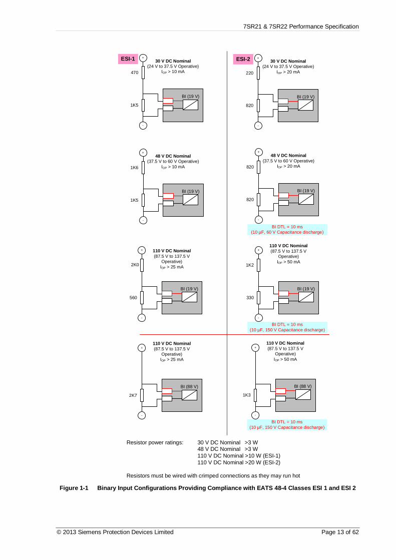
7SR21 & 7SR22 Performance Specification
© 2013 Siemens Protection Devices Limited Page 13 of 62
BI (19 V)
ESI-1 30 V DC Nominal(24 V to 37.5 V Operative)
IOP > 10 mA470
1K5
48 V DC Nominal(37.5 V to 60 V Operative)
IOP > 10 mA1K6
1K5
110 V DC Nominal(87.5 V to 137.5 V
Operative)IOP > 25 mA2K0
560
ESI-2 30 V DC Nominal(24 V to 37.5 V Operative)
IOP > 20 mA220
820
48 V DC Nominal(37.5 V to 60 V Operative)
IOP > 20 mA820
820
110 V DC Nominal(87.5 V to 137.5 V
Operative)IOP > 50 mA
1K2
330
BI DTL = 10 ms(10 µF, 60 V Capacitance discharge)
BI DTL = 10 ms(10 µF, 150 V Capacitance discharge)
BI (19 V)
BI (19 V)
BI (19 V)
BI (19 V)
BI (19 V)
+
-
+
+
+
+
+
-
-
-
-
-
Resistor power ratings: 30 V DC Nominal >3 W48 V DC Nominal >3 W110 V DC Nominal >10 W (ESI-1)110 V DC Nominal >20 W (ESI-2)
Resistors must be wired with crimped connections as they may run hot
110 V DC Nominal(87.5 V to 137.5 V
Operative)IOP > 25 mA
2K7
110 V DC Nominal(87.5 V to 137.5 V
Operative)IOP > 50 mA
1K3
BI DTL = 10 ms(10 µF, 150 V Capacitance discharge)
BI (88 V) BI (88 V)
+ +
- -
Figure 1-1 Binary Input Configurations Providing Compliance with EATS 48-4 Classes ESI 1 and ESI 2

7SR21 & 7SR22 Performance Specification
Page 14 of 62 © 2013 Siemens Protection Devices Limited
1.3 Functional Performance1.3.1 Instrumentation
Instrument Value Reference Typical accuracyI Current I ³ 0.1 xIn ± 1 % InV Voltage V ³ 0.8 xVn ± 1 % Vn
Power, real and apparent V = Vn, I ³ 0.1 xIn, pf ³ 0.8 ± 3 % Pn, where Pn = Vn x Inpf Power factor V = Vn, I ³ 0.1 xIn, pf ³ 0.8 ± 0.05
1.3.2 USB Data Communication Interface
Attribute ValuePhysical layer ElectricalConnectors USB-Type B
1.3.3 Fibre Optic Serial Data Communication Interface (Optional Rear MountedPort)
Attribute ValuePhysical layer Fibre-opticConnectors STTM (BFOC/2.5)
Recommended fibre 62.5/125 mm glass fibre with ST connectorOptical Wavelength 820 nmLaunch power (into recommended fibre) -16 dBmReceiver sensitivity -24 dBm
1.3.4 RS485 Data Communication Interface (Standard Rear Port)
Attribute ValuePhysical layer ElectricalConnectors 4 mm Ring Crimp
1.3.5 RS485 Data Communication Interface (Optional Rear Mounted Port)
Attribute ValuePhysical layer ElectricalConnectors 4-way Plug
1.3.6 RS232 Data Communication Interface (Optional Rear Mounted Port)
Attribute ValuePhysical layer ElectricalConnectors 9-way D-plug
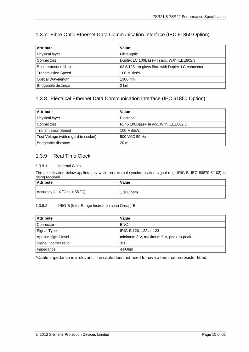
7SR21 & 7SR22 Performance Specification
© 2013 Siemens Protection Devices Limited Page 15 of 62
1.3.7 Fibre Optic Ethernet Data Communication Interface (IEC 61850 Option)
Attribute ValuePhysical layer Fibre-opticConnectors Duplex LC 100BaseF in acc. With IEEE802.3Recommended fibre 62.5/125 mm glass fibre with Duplex-LC connectorTransmission Speed 100 MBits/sOptical Wavelength 1300 nmBridgeable distance 2 km
1.3.8 Electrical Ethernet Data Communication Interface (IEC 61850 Option)
Attribute ValuePhysical layer ElectricalConnectors RJ45 100BaseF in acc. With IEEE802.3Transmission Speed 100 MBits/sTest Voltage (with regard to socket) 500 VAC 50 HzBridgeable distance 20 m
1.3.9 Real Time Clock
1.3.9.1 Internal Clock
The specification below applies only while no external synchronisation signal (e.g. IRIG-B, IEC 60870-5-103) isbeing received.Attribute Value
Accuracy (- 10 oC to + 55 oC) ± 100 ppm
1.3.9.2 IRIG-B (Inter Range Instrumentation Group)-B
Attribute ValueConnector BNCSignal Type IRIG-B 120, 122 or 123Applied signal level minimum 3 V, maximum 6 V, peak-to-peakSignal : carrier ratio 3:1Impedance 4 kOhm
*Cable impedance is irrelevant. The cable does not need to have a termination resistor fitted.

7SR21 & 7SR22 Performance Specification
Page 16 of 62 © 2013 Siemens Protection Devices Limited
1.4 Environmental Performance1.4.1 General
1.4.1.1 Temperature
IEC 60068-2-1/2
Type LevelOperating range - 10 °C to + 55 °CStorage range - 25 °C to + 70 °C
1.4.1.2 Humidity
IEC 60068-2-3
Type LevelOperational test 56 days at 40 °C and 95 % relative humidity
1.4.1.3 Transient Overvoltage
IEC 60255-5
Type LevelBetween all terminals and earth, orbetween any two independent circuits 5.0 kV, 1.2/50 ms 0.5j
1.4.1.4 Insulation
IEC 60255-5
Type LevelBetween any terminal and earth
2.5 kV AC RMS for 1 minBetween independent circuitsAcross normally open contacts 1.0 kV AC RMS for 1 min
1.4.1.5 IP Ratings
Type LevelInstalled with cover on IP 51 from front of relay
Installed with cover removed IP 20 from front of relay

7SR21 & 7SR22 Performance Specification
© 2013 Siemens Protection Devices Limited Page 17 of 62
1.4.2 Emissions
IEC 60255-25
1.4.2.1 Radiated Radio Frequency
Type Limits at 10 m, Quasi-peak30 MHz to 230 MHz 40 dB(mV/m)230 MHz to 10000 MHz 47 dB(mV/m)
1.4.2.2 Conducted Radio Frequency
TypeLimits
Quasi-peak Average0.15 MHz to 0.5 MHz 79 dB(mV) 66 dB(mV)0.5 MHz to 30 MHz 73 dB(mV) 60 dB(mV)
1.4.3 Immunity
1.4.3.1 Auxiliary DC Supply Variation
Quantity ValueAllowable superimposed ac component £ 12 % of DC voltageAllowable breaks/dips in supply(collapse to zero from nominal voltage) £ 20 ms
1.4.3.2 High Frequency Disturbance
IEC 60255-22-1 Class III
Type Level VariationCommon (longitudinal) mode 2.5 kV
£ 5 %Series (transverse) mode 1.0 kV
1.4.3.3 Electrostatic Discharge
IEC 60255-22-2 Class IV
Type Level VariationContact discharge 8.0 kV £ 5 %
1.4.3.4 Radiated Immunity
IEC 60255-22-3 Class III
Type Level Variation80 MHz to 1000 MHz 10 V/m £ 5 %

7SR21 & 7SR22 Performance Specification
Page 18 of 62 © 2013 Siemens Protection Devices Limited
1.4.3.5 Fast Transients
IEC 60255-22-4 Class A (2002)
Type Level Variation5/50 ns 2.5 kHz repetitive 4 kV £ 5 %
1.4.3.6 Surge Immunity
IEC 60255-22-5; IEC 61000-4-5
Type Level VariationAnalogue Inputs.Line to Earth.
4.0 kV ≤ 10 % or 1 mA
Case, Aux Power & I/O.Line to Earth.
2.0 kV ≤ 10 % or 1 mA
RS485 Comms Port.Line to Earth.
1.0 kV No Data Loss
Analogue Inputs.Line to Line.
1.0 kV ≤ 10 % or 1 mA
Case, Aux Power & I/O.Line to Line.
1.0 kV ≤ 10 % or 1 mA
* Note: 45 ms pick-up delay for DTL applied to binary inputs
1.4.3.7 Conducted Radio Frequency Interference
IEC 60255-22-6
Type Level Variation0.15 MHz to 80 MHz 10 V £ 5 %
1.4.3.8 Magnetic Field with Power Frequency
IEC 61000-4-8 level 5100 A/m, (0.126 mT) continuous
50 Hz1000 A/m, (1.26 mT) for 3 s

7SR21 & 7SR22 Performance Specification
© 2013 Siemens Protection Devices Limited Page 19 of 62
1.4.4 Mechanical
1.4.4.1 Vibration (Sinusoidal)
IEC 60255-21-1 Class I
Type Level VariationVibration response 0.5 gn
£ 5 %Vibration endurance 1.0 gn
1.4.4.2 Shock and Bump
IEC 60255-21-2 Class I
Type Level VariationShock response 5 gn, 11 ms
£ 5 %Shock withstand 15 gn, 11 msBump test 10 gn, 16 ms
1.4.4.3 Seismic
IEC 60255-21-3 Class I
Type Level VariationSeismic response 1 gn £ 5 %
1.4.4.4 Mechanical Classification
Type LevelDurability > 106 operations

7SR21 & 7SR22 Performance Specification
Page 20 of 62 © 2013 Siemens Protection Devices Limited
Section 2: Protection Functions
2.1 27/59 Phase Under/Over Voltage
2.1.2 Reference
Parameter ValueVs Setting 5, 5.5…199.5, 200 V
hyst Hysteresis setting 0, 0.1… 80.0 %
td Delay setting 0.00, 0.01…20.00, 20.50… 100, 101… 1000, 1010…10000, 10100… 14400 s
2.1.3 Operate and Reset Level
Attribute ValueVop Operate level 100 % Vs, ± 1 % or ±0.25 V
Reset levelOvervoltage = (100 % - hyst) x Vop, ± 1 % or ±0.25 VUndervoltage = (100 % + hyst) x Vop, ± 1 % or ±0.25 V
Repeatability ± 1 %
Variation-10 °C to +55 °C £ 5 %
fnom - 3 Hz to fnom + 2 Hz £ 5 %
2.1.4 Operate and Reset Time
Attribute Value
tbasicEElement basicoperate time
Overvoltage0 to 1.1 x Vs: 73 ms ± 10 ms
0 to 2.0 xVs: 63 ms ± 10 msUndervoltage 1.1 to 0.5 xVs: 58 ms ± 10 ms
top Operate time following delay tbasic + td, ± 1 % or ± 10 ms
Repeatability ± 1 % or ± 10 ms
Disengaging time < 80 ms

7SR21 & 7SR22 Performance Specification
© 2013 Siemens Protection Devices Limited Page 21 of 62
2.2 27/59 Vx Under/Over Voltage
2.2.1 Reference
Parameter ValueVs Setting 5, 5.5…199.5, 200 V
VsGuard
Guard Setting 1, 1.5, …199.5, 200 V
hyst Hysteresis setting 0, 0.1… 80.0 %
td Delay setting 0.00, 0.01…20.00, 20.50… 100, 101… 1000, 1010…10000, 10100… 14400 s
2.2.2 Operate and Reset Level
Attribute ValueVop Operate level 100 % Vs, ± 1 % or ±0.25 V
Reset levelOvervoltage = (100 % - hyst) x Vop, ± 1 % or ± 0.25 V
Undervoltage = (100 % + hyst) x Vop, ± 1 % or ± 0.25 V
Repeatability ± 1 %
Variation-10 °C to +55 °C £ 5 %
fnom - 3 Hz to fnom + 2 Hz £ 5 %
2.2.3 Operate and Reset Time
Attribute Value
tbasicEElement basicoperate time
Overvoltage0 to 1.1 x Vs: 73 ms ± 10 ms
0 to 2.0 xVs: 63 ms ± 10 msUndervoltage 1.1 to 0.5 xVs: 58 ms ± 10 ms
top Operate time following delay tbasic + td, ± 1 % or ± 10 ms
Repeatability ± 1 % or ± 10 ms
Disengaging time < 80 ms

7SR21 & 7SR22 Performance Specification
Page 22 of 62 © 2013 Siemens Protection Devices Limited
2.3 37 Undercurrent
2.3.1 Reference
Parameter ValueIs Setting 0.05, 0.10…5.0 xIn
td Delay setting 0.00, 0.01…20.00, 20.50… 100, 101… 1000, 1010…10000, 10100… 14400 s
Is 37-n U/I Guard Setting 0.05, 0.10…5.0 xIn
2.3.2 Operate and Reset Level
Attribute ValueIop Operate level 100 % Is, ± 5 % or ± 1% In
Reset level £ 105 % Iop
Repeatability ± 1 %
Variation-10 °C to +55 °C £ 5 %
fnom - 3 Hz to fnom + 2 Hz £ 5 %
2.3.3 Operate and Reset Time
Attribute Valuetbasic Element basic operate time 1.1 to 0.5 xIs: 35 ms, ± 10ms
top Operate time following delay tbasic + td, ± 1 % or ± 10ms
Repeatability ± 1 % or ± 10ms
Overshoot time < 40 ms
Disengaging time < 60 ms

7SR21 & 7SR22 Performance Specification
© 2013 Siemens Protection Devices Limited Page 23 of 62
2.4 37G & 37SEF Undercurrent
2.4.1 Reference
Parameter ValueIs Setting 0.005, 0.10…5.0 xIn
td Delay setting 0.00, 0.01…20.00, 20.50… 100, 101… 1000, 1010…10000, 10100… 14400 s
2.4.2 Operate and Reset Level
Attribute ValueIop Operate level 100 % Is, ± 5 % or ± 1% In
Reset level £ 105 % Iop or Iop ± 0.1 % In
Repeatability ± 1 %
Variation-10 °C to +55 °C £ 5 %
fnom - 3 Hz to fnom + 2 Hz £ 5 %
2.4.3 Operate and Reset Time
Attribute Valuetbasic Element basic operate time 1.1 to 0.5 xIs: 35 ms, ± 10 ms
top Operate time following delay tbasic + td, ± 1 % or ± 10 ms
Repeatability ± 1 % or ± 10 ms
Overshoot time < 40 ms
Disengaging time < 60 ms

7SR21 & 7SR22 Performance Specification
Page 24 of 62 © 2013 Siemens Protection Devices Limited
2.5 46NPS Negative Phase Sequence Overcurrent
2.5.1 Reference (46DT)
Parameter ValueIs Setting 0.05, 0.06... 4.0xIn
td Delay setting 0.00, 0.01…20.00, 20.50… 100, 101… 1000, 1010…10000, 10100… 14400 s
2.5.2 Operate and Reset Level (46DT)
Attribute ValueIop Operate level 100 % Is, ± 5 % or ± 1% In
Reset level ³ 95 % Iop
Repeatability ± 1 %Transient overreach(X/R £ 100) £ -5 %
Variation-10 °C to +55 °C £ 5 %
fnom - 3 Hz to fnom + 2 Hz £ 5 %
2.5.3 Operate and Reset Time (46DT)
Attribute Value
tbasic Element basic operate time0 to 2 xIs: 40 ms, ± 10 ms
0 to 5 xIs: 30 ms, ± 10 mstop Operate time following delay tbasic + td, ± 1 % or ± 10 ms
Repeatability ± 1 % or ± 10 ms
Overshoot time <40 ms
Disengaging time < 60 ms
2.5.4 Reference (46IT)
Parameter Valuechar Characteristic setting IEC-NI, -VI, -EI, -LTI; ANSI-MI, -VI, -EI; DTLTm Time Multiplier setting 0.025, 0.050 … 1.6Is Setting 0.05, 0.06… 2.5xInI Applied Current (for operate time) IDMTL 2 to 20 x Istd Delay setting 0, 0.01… 20 stres Reset setting ANSI DECAYING, 0, 1… 60 s

7SR21 & 7SR22 Performance Specification
© 2013 Siemens Protection Devices Limited Page 25 of 62
Operate and Reset Level (46IT)
Attribute ValueIop Operate level 105 % Is, ± 4 % or ± 1% In
Reset level (100%-Hyst.) x Vop ± 1% or ± 0.25 V
Repeatability ± 1 %
Variation-10 °C to +55 °C £ 5 %
fnom - 3 Hz to fnom + 2 Hz £ 5 %
2.5.5 Operate and Reset Time (46IT)
Attribute ValueStarter operate time (³ 2xIs) 35 ms, ± 10 ms
top Operate time
char = IEC-NI,IEC-VI,IEC-EI,IEC-LTI
[ ]TmKt
IsI
op ´-
=1a
, ± 5 % absolute or ± 50 ms,
for char = IEC-NI : K = 0.14, a = 0.02IEC-VI : K = 13.5, a = 1.0IEC-EI : K = 80.0, a = 2.0
IEC-LTI : K = 120.0, a = 1.0
char = ANSI-MI,ANSI-VI,ANSI-EI
[ ]TmBAt
PIsI
op ´úú
û
ù
êê
ë
é+
-=
1, ± 5 % absolute or ± 50 ms,
for char = ANSI-MI : A = 0.0515, B = 0.114, P = 0.02ANSI-VI : A = 19.61, B = 0.491, P = 2.0ANSI-EI : A = 28.2, B = 0.1217, P = 2.0
char = DTL td, ± 1 % or ± 20 ms
Reset timeANSI DECAYING
[ ] TmRtIsIres ´
-=
12 , ± 5 % absolute or ± 50 ms,
for char = ANSI-MI : R = 4.85ANSI-VI : R = 21.6ANSI-EI : R = 29.1
tres tres, ± 1 % or ± 20 ms
Repeatability ± 1 % or ± 20 ms
Overshoot time < 40 ms
Disengaging time < 60 ms
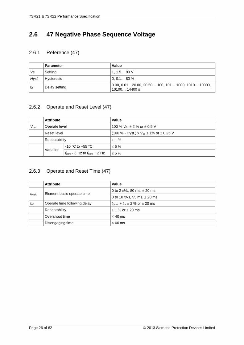
7SR21 & 7SR22 Performance Specification
Page 26 of 62 © 2013 Siemens Protection Devices Limited
2.6 47 Negative Phase Sequence Voltage
2.6.1 Reference (47)
Parameter ValueVs Setting 1, 1.5… 90 V
Hyst. Hysteresis 0, 0.1… 80 %
td Delay setting 0.00, 0.01…20.00, 20.50… 100, 101… 1000, 1010… 10000,10100… 14400 s
2.6.2 Operate and Reset Level (47)
Attribute ValueVop Operate level 100 % Vs, ± 2 % or ± 0.5 V
Reset level (100 % - Hyst.) x Vop ± 1% or ± 0.25 V
Repeatability ± 1 %
Variation-10 °C to +55 °C £ 5 %
fnom - 3 Hz to fnom + 2 Hz £ 5 %
2.6.3 Operate and Reset Time (47)
Attribute Value
tbasic Element basic operate time0 to 2 xVs, 80 ms, ± 20 ms
0 to 10 xVs, 55 ms, ± 20 mstop Operate time following delay tbasic + td, ± 2 % or ± 20 ms
Repeatability ± 1 % or ± 20 ms
Overshoot time < 40 ms
Disengaging time < 60 ms
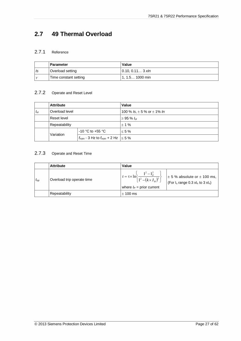
7SR21 & 7SR22 Performance Specification
© 2013 Siemens Protection Devices Limited Page 27 of 62
2.7 49 Thermal Overload
2.7.1 Reference
Parameter ValueIs Overload setting 0.10, 0.11… 3 xIn
t Time constant setting 1, 1.5… 1000 min
2.7.2 Operate and Reset Level
Attribute ValueIol Overload level 100 % Is, ± 5 % or ± 1% In
Reset level ³ 95 % Iol
Repeatability ± 1 %
Variation-10 °C to +55 °C £ 5 %
fnom - 3 Hz to fnom + 2 Hz £ 5 %
2.7.3 Operate and Reset Time
Attribute Value
top Overload trip operate time ( ) þýü
îíì
´--
´t= 22
2P
2
IIIln
BIkt
where IP = prior current
± 5 % absolute or ± 100 ms,(For Is range 0.3 xIn to 3 xIn)
Repeatability ± 100 ms

7SR21 & 7SR22 Performance Specification
Page 28 of 62 © 2013 Siemens Protection Devices Limited
0.1
1
10
100
1000
10000
100000
0 1 2 3 4 5 6 7 8 9 10Current (multiple of setting)
Time(sec)
t = 1000 mins
t = 100 mins
t = 10 mins
t = 1 min
Figure 2-1 Thermal Overload Protection Curves

7SR21 & 7SR22 Performance Specification
© 2013 Siemens Protection Devices Limited Page 29 of 62
2.8 50 Instantaneous Overcurrent
2.8.1 Reference
Parameter ValueIs Setting 0.05, 0.06… 25, 25.5… 50 xIn
i Applied Current (for operate time) 2 to 5 x Is
td Delay setting 0.00, 0.01…20.00, 20.50… 100, 101… 1000, 1010…10000, 10100… 14400 s
2.8.2 Operate and Reset Level
Attribute ValueIop Operate level 100 % Is, ± 5 % or ± 1% In
Reset level ³ 95 % Iop
Repeatability ± 1 %Transient overreach(X/R £ 100) £ -5 %
Variation-10 °C to +55 °C £ 5 %
fnom - 3 Hz to fnom + 2 Hz £ 5 %
2.8.3 Operate and Reset Time
Attribute Value
tbasic Element basic operate time0 to 2 xIs: 35 ms, ± 10 ms
0 to 5 xIs: 25 ms, ± 10 mstop Operate time following delay tbasic + td, ± 1 % or ± 10 ms
Repeatability ± 1 % or ± 10 ms
Overshoot time < 40 ms
Disengaging time < 50 ms

7SR21 & 7SR22 Performance Specification
Page 30 of 62 © 2013 Siemens Protection Devices Limited
2.9 50G Instantaneous Measured Earth Fault
2.9.1 Reference
Parameter ValueIs Setting 0.005, 0.006… 25 xIn
i Applied Current (for operate time) 2 to 5 x Is
td Delay setting 0.00, 0.01…20.00, 20.50… 100, 101… 1000, 1010…10000, 10100… 14400 s
2.9.2 Operate and Reset Level
Attribute ValueIop Operate level 100 % Is, ± 5 % or ± 1% In
Reset level ³ 95 % Iop
Repeatability ± 1 %Transient overreach(X/R £ 100) £ -5 %
Variation-10 °C to +55 °C £ 5 %
fnom - 3 Hz to fnom + 2 Hz £ 5 %
2.9.3 Operate and Reset Time
Attribute Value
tbasic Element basic operate time0 to 2 xIs: 35 ms, ± 10 ms
0 to 5 xIs: 25 ms, ± 10 mstop Operate time following delay tbasic + td, ± 1 % or ± 10 ms
Repeatability ± 1 % or ± 10 ms
Overshoot time < 40 ms
Disengaging time < 50 ms

7SR21 & 7SR22 Performance Specification
© 2013 Siemens Protection Devices Limited Page 31 of 62
2.10 50N instantaneous Derived Earth Fault
2.10.1 Reference
Parameter ValueIs Setting 0.05, 0.06… 25, 25.5… 50 xIn
td Delay setting 0.00, 0.01…20.00, 20.50… 100, 101… 1000, 1010…10000, 10100… 14400 s
2.10.2 Operate and Reset Level
Attribute ValueIop Operate level 100 % Is, ± 5 % or ± 1% In
Reset level ³ 95 % Iop
Repeatability ± 1 %Transient overreach(X/R £ 100) £ -5 %
Variation-10 °C to +55 °C £ 5 %
fnom - 3 Hz to fnom + 2 Hz £ 5 %
2.10.3 Operate and Reset Time
Attribute Value
tbasic Element basic operate time0 to 2 xIs: 35 ms, ± 10 ms
0 to 5 xIs: 25 ms, ± 10 ms
top Operate time following delay tbasic + td, ± 1 % or ± 10 ms
Repeatability ± 1 % or ± 10 ms
Overshoot time < 40 ms
Disengaging time < 50 ms

7SR21 & 7SR22 Performance Specification
Page 32 of 62 © 2013 Siemens Protection Devices Limited
2.11 50SEF Instantaneous Sensitive Earth Fault
2.11.1 Reference
Parameter Value
Is Setting 0.005, 0.006… 5.0 xIn
td Delay setting 0.00, 0.01… 20.0, 20.1 .. 100.0, 101.…1000, 1010 …10000 , 10100 … 14400
I Applied current (for operate time) 5 xIs
2.11.2 Operate and Reset Level
Attribute Value
Iop Operate level 100 % Is, ± 5 % or ± 1% In
Reset level 95 % Iop ± 5 % or ± 0.1% In
Repeatability ± 1 %
Transient overreach(X/R £ 100) £ -5 %
Variation
-10 °C to +55 °C £ 5 %
fnom - 3 Hz to fnom + 2 Hz
harmonics to fcutoff
£ 5 %
2.11.3 Operate and Reset Time
Attribute Value
tbasic Element basic operate time0 to 2 xIs: 35 ms, ± 10 ms
0 to 5 xIs: 25 ms, ± 10 ms
top Operate time following delay tbasic + td, ± 1 % or ± 10 ms
Repeatability ± 1 % or ± 10 ms
Overshoot time < 40 ms
Disengaging time < 50 ms
Variation fnom - 3 Hz to fnom + 2 Hz £ 5 %

7SR21 & 7SR22 Performance Specification
© 2013 Siemens Protection Devices Limited Page 33 of 62
2.12 51 Time Delayed Overcurrent
2.12.1 Reference
Parameter ValueIs Setting 0.05, 0.06… 2.5 xIn
char Characteristic settingIEC-NI, -VI, -EI, -LTI;ANSI-MI, -VI, -EI; DTL
Tm Time Multiplier setting 0.025, 0.05… 1.6
td Delay setting 0, 0.01… 20 s
tres Reset setting ANSI DECAYING, 0, 1… 60 s
I Applied Current(for operate time)
IDMTL 2 to 20 x ls
DTL 5 x Is
2.12.2 Operate and Reset Level
Attribute ValueIop Operate level 105 % Is, ± 4 % or ± 1 % In
Reset level ³ 95 % Iop
Repeatability ± 1 %
Variation- 10 °C to + 55 °C £ 5 %
fnom - 3 Hz to fnom + 2 Hz £ 5 %

7SR21 & 7SR22 Performance Specification
Page 34 of 62 © 2013 Siemens Protection Devices Limited
2.12.3 Operate and Reset Time
Attribute ValueStarter operate time (³ 2xIs) 20 ms, ± 20 ms
top Operate time
char = IEC-NI,IEC-VI,IEC-EI,IEC-LTI
[ ]TmKt
IsI
op ´-
=1a
, ± 5 % absolute or ± 30 ms,
for char = IEC-NI : K = 0.14, a = 0.02IEC-VI : K = 13.5, a = 1.0IEC-EI : K = 80.0, a = 2.0
IEC-LTI : K = 120.0, a = 1.0
char = ANSI-MI,ANSI-VI,ANSI-EI
[ ]TmBAt
PIsI
op ´úú
û
ù
êê
ë
é+
-=
1, ± 5 % absolute or ± 30 ms,
for char = ANSI-MI : A = 0.0515, B = 0.114, P = 0.02ANSI-VI : A = 19.61, B = 0.491, P = 2.0ANSI-EI : A = 28.2, B = 0.1217, P = 2.0
char = DTL td, ± 1 % or ± 20ms
Reset timeANSI DECAYING
[ ]TmRt
IsIres ´
-=
12 , ± 5 % absolute or ± 30 ms,
for char = ANSI-MI : R = 4.85ANSI-VI : R = 21.6ANSI-EI : R = 29.1
tres tres, ± 1 % or ± 20 ms
Repeatability ± 1 % or ± 20 ms
Overshoot time < 40 ms
Disengaging time < 50 ms
Figure 2.2 shows the operate times for the four IEC IDMTL curves with a time multiplier of 1. Figure 2.3 andFigure 2.4 show the ANSI operate and reset curves. These operate times apply to non-directional characteristics.Where directional control is applied then the directional element operate time should be added to give totalmaximum operating time.
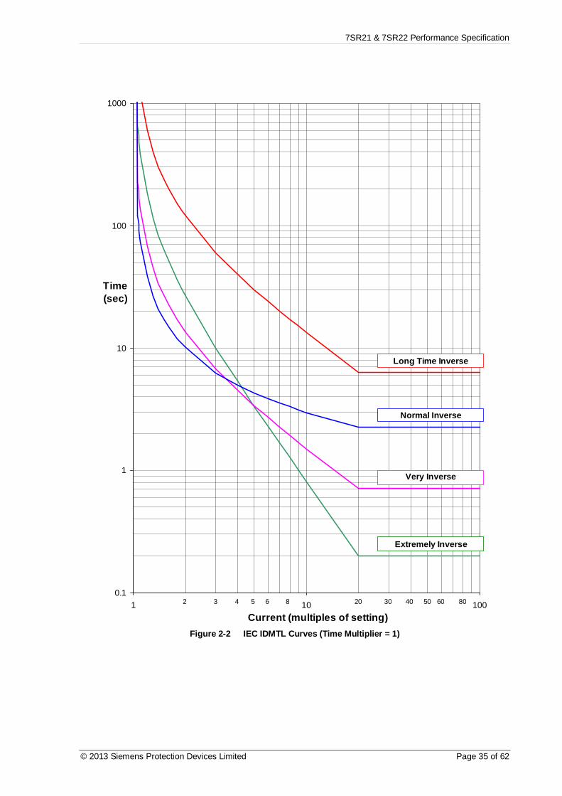
7SR21 & 7SR22 Performance Specification
© 2013 Siemens Protection Devices Limited Page 35 of 62
0.1
1
10
100
1000
1 10 100Current (multiples of setting)
Time(sec)
2 3 4 5 6 8 20 30 40 50 60 80
Long Time Inverse
Normal Inverse
Very Inverse
Extremely Inverse
Figure 2-2 IEC IDMTL Curves (Time Multiplier = 1)

7SR21 & 7SR22 Performance Specification
Page 36 of 62 © 2013 Siemens Protection Devices Limited
0.1
1
10
100
1000
1 10 100Current (multiples of setting)
Time(sec)
2 3 4 5 6 8 20 30 40 50 60 80
Moderately Inverse
Extremely Inverse
Very Inverse
Figure 2-3 ANSI IDMTL Operate Curves (Time Multiplier = 1)

7SR21 & 7SR22 Performance Specification
© 2013 Siemens Protection Devices Limited Page 37 of 62
1
10
100
1000
0.1 1
Current (multiples of setting)
Time(sec)
Moderately Inverse
Extremely Inverse
Very Inverse
0.2 0.3 0.4 0.5 0.6 0.8 0.90.7
5
50
500
Figure 2-4 ANSI IDMTL Reset Curves (Time Multiplier = 1)

7SR21 & 7SR22 Performance Specification
Page 38 of 62 © 2013 Siemens Protection Devices Limited
2.13 51G Time Delayed Measured Earth Fault
2.13.1 Reference
Parameter ValueIs Setting 0.005, 0.006… 1.0 xIn
Char Characteristic settingIEC-NI, -VI, -EI, -LTI;ANSI-MI, -VI, -EI; DTL
Tm Time Multiplier setting 0.025, 0.05… 1.6
td Delay setting (DTL) 0, 0.01… 20 s
tres Reset setting ANSI DECAYING, 0, 1… 60 s
I Applied current (foroperate time)
IDMTL 2 to 20 xIsDTL 5 xIs
2.13.2 Operate and Reset Level
Attribute ValueIop Operate level 105 % Is, ± 4 % or ± 1% In
Reset level ³ 95 % Iop
Repeatability ± 1 %
Variation-10 °C to +55 °C £ 5 %
fnom - 3 Hz to fnom + 2 Hz £ 5 %

7SR21 & 7SR22 Performance Specification
© 2013 Siemens Protection Devices Limited Page 39 of 62
2.13.3 Operate and Reset Time
Attribute ValueStarter operate time (³ 2 xIs) 20 ms, ± 20 ms
top Operate time
char = IEC-NI,IEC-VI,IEC-EI,IEC-LTI
[ ]TmKt
IsI
op ´-
=1a
, ± 5 % absolute or ± 30 ms,
for char = IEC-NI : K = 0.14, a = 0.02IEC-VI : K = 13.5, a = 1.0IEC-EI : K = 80.0, a = 2.0
IEC-LTI : K = 120.0, a = 1.0
char = ANSI-MI,ANSI-VI,ANSI-EI
[ ]TmBAt
PIsI
op ´úú
û
ù
êê
ë
é+
-=
1, ± 5 % absolute or ± 30 ms,
for char = ANSI-MI : A = 0.0515, B = 0.114, P = 0.02ANSI-VI : A = 19.61, B = 0.491, P = 2.0ANSI-EI : A = 28.2, B = 0.1217, P = 2.0
char = DTL td, ± 1 % or ± 20 ms
Reset timeANSI DECAYING
[ ]TmRt
IsIres ´
-=
12 , ± 5 % absolute or ± 30 ms,
for char = ANSI-MI : R = 4.85ANSI-VI : R = 21.6ANSI-EI : R = 29.1
tres tres, ± 1 % or ± 20 ms
Repeatability ± 1 % or ± 20 ms
Overshoot time < 40 ms
Disengaging time < 50 ms
Figure 2-2 shows the operate times for the four IEC IDMTL curves with a time multiplier of 1. Figure 2-3 andFigure 2-4 show the ANSI operate and reset curves respectively. These operate times apply to non-directionalcharacteristics. Where directional control is applied then the directional element operate time should be added togive total maximum operating time.

7SR21 & 7SR22 Performance Specification
Page 40 of 62 © 2013 Siemens Protection Devices Limited
2.14 51N Time Delayed Derived Earth Fault
2.14.1 Reference
Parameter ValueIs Setting 0.05, 0.06… 2.5 xIn
char Characteristic settingIEC-NI, -VI, -EI, -LTI;ANSI-MI, -VI, -EI; DTL
Tm Time Multiplier setting 0.025, 0.05… 1.6
td Delay setting 0, 0.01… 20 s
tres Reset setting ANSI DECAYING, 0, 1… 60 s
2.14.2 Operate and Reset Level
Attribute ValueIop Operate level 105 % Is, ± 4 % or ± 1% In
Reset level ³ 95 % Iop
Repeatability ± 1 %
Variation- 10 °C to + 55 °C £ 5 %
fnom - 3 Hz to fnom + 2 Hz £ 5 %
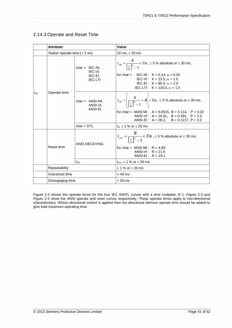
7SR21 & 7SR22 Performance Specification
© 2013 Siemens Protection Devices Limited Page 41 of 62
2.14.3 Operate and Reset Time
Attribute ValueStarter operate time (³ 2 xIs) 20 ms, ± 20 ms
top Operate time
char = IEC-NI,IEC-VI,IEC-EI,IEC-LTI
[ ]TmKt
IsI
op ´-
=1a
, ± 5 % absolute or ± 30 ms,
for char = IEC-NI : K = 0.14, a = 0.02IEC-VI : K = 13.5, a = 1.0IEC-EI : K = 80.0, a = 2.0
IEC-LTI : K = 120.0, a = 1.0
char = ANSI-MI,ANSI-VI,ANSI-EI
[ ]TmBAt
PIsI
op ´úú
û
ù
êê
ë
é+
-=
1, ± 5 % absolute or ± 30 ms,
for char = ANSI-MI : A = 0.0515, B = 0.114, P = 0.02ANSI-VI : A = 19.61, B = 0.491, P = 2.0ANSI-EI : A = 28.2, B = 0.1217, P = 2.0
char = DTL td, ± 1 % or ± 20 ms
Reset timeANSI DECAYING
[ ]TmRt
IsIres ´
-=
12 , ± 5 % absolute or ± 30 ms,
for char = ANSI-MI : R = 4.85ANSI-VI : R = 21.6ANSI-EI : R = 29.1
tres tres, ± 1 % or ± 20 ms
Repeatability ± 1 % or ± 20 ms
Overshoot time < 40 ms
Disengaging time < 50 ms
Figure 2-2 shows the operate times for the four IEC IDMTL curves with a time multiplier of 1. Figure 2-3 andFigure 2-4 show the ANSI operate and reset curves respectively. These operate times apply to non-directionalcharacteristics. Where directional control is applied then the directional element operate time should be added togive total maximum operating time.
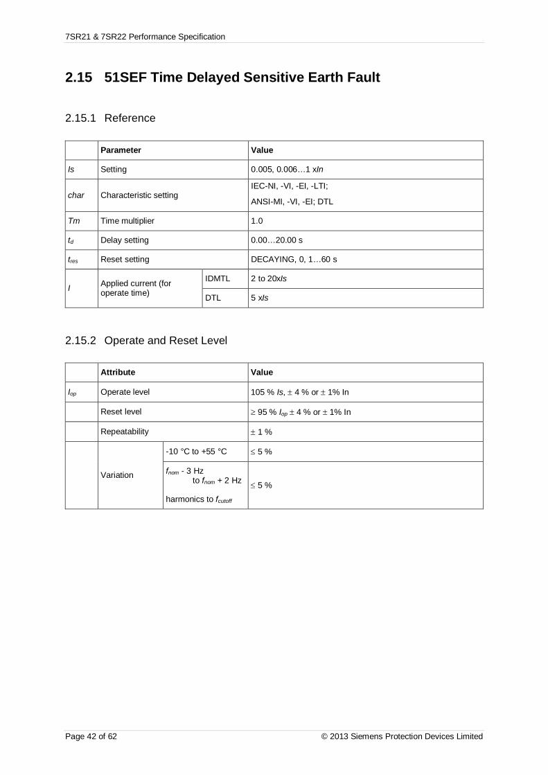
7SR21 & 7SR22 Performance Specification
Page 42 of 62 © 2013 Siemens Protection Devices Limited
2.15 51SEF Time Delayed Sensitive Earth Fault
2.15.1 Reference
Parameter Value
Is Setting 0.005, 0.006…1 xIn
char Characteristic settingIEC-NI, -VI, -EI, -LTI;
ANSI-MI, -VI, -EI; DTL
Tm Time multiplier 1.0
td Delay setting 0.00…20.00 s
tres Reset setting DECAYING, 0, 1…60 s
I Applied current (foroperate time)
IDMTL 2 to 20xIs
DTL 5 xIs
2.15.2 Operate and Reset Level
Attribute Value
Iop Operate level 105 % Is, ± 4 % or ± 1% In
Reset level ³ 95 % Iop ± 4 % or ± 1% In
Repeatability ± 1 %
Variation
-10 °C to +55 °C £ 5 %
fnom - 3 Hzto fnom + 2 Hz
harmonics to fcutoff
£ 5 %

7SR21 & 7SR22 Performance Specification
© 2013 Siemens Protection Devices Limited Page 43 of 62
2.15.3 Operate and Reset Time
Attribute Value
Starter operate time 20 ms, ± 20 ms
top Operate time
char = IEC-NI,IEC-VI,IEC-EI,IEC-LTI
[ ]TmKt
IsI
op ´-
=1a
, ± 5 % absolute or ± 30 ms,
for char = IEC-NI : K = 0.14, a = 0.02IEC-VI : K = 13.5, a = 1.0IEC-EI : K = 80.0, a = 2.0
IEC-LTI : K = 120.0, a = 1.0
char = ANSI-MI,ANSI-VI,ANSI-EI,
[ ]TmBAt
PIsI
op ´úú
û
ù
êê
ë
é+
-=
1, ± 5 % absolute or ± 30 ms,
for char = ANSI-MI : A = 0.0515, B = 0.114, P = 0.02ANSI-VI : A = 19.61, B = 0.491, P = 2.0ANSI-EI : A = 28.2, B = 0.1217, P = 2.0
char = DTL td, ± 1 % or ± tcycle
Reset time
char = ANSI andtres = DECAYING
[ ]TmRt
IsIres ´
-=
12 , ± 5 % absolute or ± 30 ms,
for char = ANSI-MI : R = 4.85ANSI-VI : R = 21.6ANSI-EI : R = 29.1
tres ¹ DECAYING tres, ± 1 % or ± 20 ms
Repeatability ± 1 % or ± 20 ms
Overshoot time < 40 ms
Disengaging time < 50 ms
Variationfnom - 3 Hz
to fnom + 2 Hz
harmonics to fcutoff
£ 5 %
Figure 2-2 shows the operate times for the four IEC IDMTL curves with a time multiplier of 1. Figure 2-3 andFigure 2-4 show the ANSI operate and reset curves. These operate times apply to non-directional characteristics.Where directional control is applied then the directional element operate time should be added to give totalmaximum operating time.

7SR21 & 7SR22 Performance Specification
Page 44 of 62 © 2013 Siemens Protection Devices Limited
2.16 51V Voltage Controlled Overcurrent (Ph-Ph)
2.16.1 Reference
Parameter Value
Vs Setting 5, 5.5…199.5, 200 V
m Multiplier 0.25, 0.3…0.95, 1
Is Setting 1 xIn
2.16.2 Operate and Reset Level
Attribute Value
Vop Operate level 100 % Vs, ± 1 % or ± 0.25 V
Reset level £ 105 % Vop
Repeatability ± 1 %
Variation
-10 °C to +55 °C £ 5 %
fnom - 3 Hzto fnom + 2 Hz
harmonics to fcutoff
£ 5 %
Operate and Reset Time
As per Phase Fault Shaped Characteristic Element (ANSI 51).
Where Pickup Level = Is for Voltage > Vs
Pickup Level = (Is x m) for Voltage < Vs

7SR21 & 7SR22 Performance Specification
© 2013 Siemens Protection Devices Limited Page 45 of 62
2.17 59N Neutral Voltage Displacement
2.17.1 Reference (59NDT)
Parameter ValueVs Setting 1, 1.5… 100 V
td Delay setting 0.00, 0.01…20.00, 20.50… 100, 101… 1000, 1010… 10000,10100… 14400 s
2.17.2 Operate and Reset Level (59NDT)
Attribute ValueVop Operate level 100 % Vs, ± 2 % or ± 0.5 V
Reset level ³ 95 % Vop or ± 0.25 V
Repeatability ± 1 %
Variation-10 °C to +55 °C £ 5 %
fnom - 3 Hz to fnom + 2 Hz £ 5 %
2.17.3 Operate and Reset Time (59NDT)
Attribute Value
tbasic Element basic operate time0V to 1.5 xVs, 76 ms, ± 20 ms
0V to 10 xVs, 63 ms, ± 20 mstop Operate time following delay tbasic + td, ± 1 % or ± 20 ms
Repeatability ± 1 % or ± 20 ms
Overshoot time < 40 ms
Disengaging time < 50 ms
2.17.4 Reference (59NIT)
Parameter ValueM Multiplier setting 0.1, 0.2… 10, 10.5… 140
Vs Setting 1, 1.5… 100 V
td Delay setting 0, 0.01… 20 s
tres Reset setting 0, 1…60 s

7SR21 & 7SR22 Performance Specification
Page 46 of 62 © 2013 Siemens Protection Devices Limited
2.17.5 Operate and Reset Level (59NIT)
Attribute ValueVop Operate level 105 % Vs, ± 2 % or ± 0.5 V
Reset level ³ 95 % Vop or ± 0.25 V
Repeatability ± 1 %
Variation-10 °C to +55 °C £ 5 %
fnom - 3 Hz to fnom + 2 Hz £ 5 %
2.17.6 Operate and Reset Time (59NIT)
Attribute Value
tbasic Starter operate time (³ 2xVs) 65 ms, ± 20 ms
topOperatetime
char = IDMTL [ ] 1Mt
Vs0V3op -
= , ± 5 % or ± 65 ms
char = DTL td, ± 1 % or ± 40 ms
Reset Timechar = IDMTL tres, ± 5 % or ± 65 ms
char = DTL tres, ± 1 % or ± 40 ms
Repeatability ± 1 % or ± 20 ms
Overshoot time < 40 ms
Disengaging time < 50 ms

7SR21 & 7SR22 Performance Specification
© 2013 Siemens Protection Devices Limited Page 47 of 62
2.18 64H Restricted Earth Fault Protection
2.18.1 Reference
Parameter ValueIs Setting 0.005, 0.006… 0.95 xIn
td Delay setting 0.00, 0.01… 20.0, 20.1… 100.0, 101.…1000, 1010 …10000 , 10100 … 14400 s
2.18.2 Operate and Reset Level
Attribute ValueIop Operate level 100 % Is, ± 5 % or ±1 % xIn
Reset level 95 % Iop, ± 5 % or ±0.1 % xIn
Repeatability ± 1 %
Transient overreach(X/R £ 100) £ -5 %
Variation-10 °C to +55 °C £ 5 %
fnom - 3 Hz to fnom + 2 Hz £ 5 %
2.18.3 Operate and Reset Time
Attribute Value
tbasic Element basic operate time0 to 2 xIs, 40 ms, ± 10 ms
0 to 5 xIs, 30 ms, ± 10 mstop Operate time following delay tbasic + td, ± 1% or ± 10 ms
Repeatability ± 1% or ± 10 ms
Overshoot time < 40 ms
Disengaging time < 50 ms

7SR21 & 7SR22 Performance Specification
Page 48 of 62 © 2013 Siemens Protection Devices Limited
2.19 67/67N Directional Overcurrent & Earth Fault
2.19.1 Reference
Parameter Value
us Angle setting -95…+95 °
I Applied current In
V Applied voltage 110 V phase-phase (63.5 V phase-earth)
2.19.2 Operate Angle
Attribute Value
CA Characteristic angle (I with respectto V) us, ± 5 °
Operating angleforward CA - 85 ° ± 5 ° to CA + 85° ± 5 °
reverse (CA - 180°) - 85° ± 5 ° to (CA - 180°) + 85° ± 5 °
Variation incharacteristicangle
10°C to +55°C ± 5 °
fnom - 3 Hz to fnom + 2 Hz ± 5 °
2.19.3 Operate Threshold
Attribute Value
Minimum levels foroperation
I (p/f) > 5 % In
I (e/f) > 10 % In
V (p/f) > 1 V
V (e/f) > 1 V
2.19.4 Operate and Reset Time
Attribute Value
Operate time typically 32 < 40 ms at characteristic angle
Reset time typically < 65 ms at characteristic angle

7SR21 & 7SR22 Performance Specification
© 2013 Siemens Protection Devices Limited Page 49 of 62
2.20 81 Under/Over Frequency
2.20.1 Reference
Parameter ValueFs Setting 40, 40.01… 69.99 Hz
Hyst Hysteresis setting 0, 0.1… 80 %
td Delay setting 0.00, 0.01… 20.0, 20.1… 100.0, 101.…1000, 1010 … 10000 ,10100 … 14400 s
2.20.2 Operate and Reset Level
Attribute ValueFop Operate level 100 % Fs, ± 10 mHz
Reset leveloverfrequency (100 % - hyst) xFop, ± 10 mHzunderfrequency (100 % + hyst) xFop, ± 10 mHz
Repeatability ± 1 %
Variation - 10 °C to + 55 °C £ 5 %
2.20.3 Operate and Reset Time
Attribute Value
tbasic
Element basicoperate time(for ROCOFbetween 0.1and 5.0 Hz/sec)
overfrequencyTypically < 110 ms
Maximum < 150 ms
underfrequencyTypically < 110 ms
Maximum < 150 mstop Operate time following delay tbasic + td, ± 1 % or ± 10 ms
Repeatability ± 1 % or ± 10 ms
Disengaging time < 100 ms

7SR21 & 7SR22 Performance Specification
Page 50 of 62 © 2013 Siemens Protection Devices Limited
2.21 50 AFD ARC Flash Detector(Refer to 7XG31 Technical Manual for performance characteristics)
2.21.1 Reference
Parameter Value50 AFD Setting 1, 2,...10 xIn
2.21.2 Operate and Reset Level
Attribute ValueIop Operate level 100 % Is, ± 10 % or ± 1% In
Reset level ³ 95 % Iop
Repeatability ± 1 %
Transient overreach (X/R £ 100) £ -5 %
2.21.3 Operate and Reset Time
Attribute Valuetbasic 50AFD Overcurrent operate time 10 ms – 16 mstop AFD Zone operate time (Flash & 50AFD) 15 ms – 25 ms
Repeatability ± 1 % or ± 10 msDisengaging time < 50 ms

7SR21 & 7SR22 Performance Specification
© 2013 Siemens Protection Devices Limited Page 51 of 62
Section 3: Supervision Functions
3.1 46BC & 46BC U/C Broken Conductor
3.1.1 Reference
Parameter Value
Setting (NPS to PPS ratio) 20…100 %
U/C Guard setting 0.05, 0.1 ... 4.95, 5
tf Delay setting 0.02…1000 s
3.1.2 Operate and Reset Level
Attribute Value
Icurr Operate level 100 % Iset ± 5 %
Reset level 90 % Icurr , ± 5 %
Repeatability ± 1 %
Variation
- 10 °C to + 55 °C £ 5 %
fnom - 3 Hz to fnom + 2 Hz
harmonics to fcutoff
£ 5 %
3.1.3 Operate and Reset Time
Attribute Value
tbasic Basic operate time 1x In to 0 A 40 ms
Operate time tf + tbasic, ± 1 % or ± 20 ms
Repeatability ± 1 % or ± 20 ms
Variationfnom - 3 Hz to fnom + 2 Hz
harmonics to fcutoff
£ 5 %

7SR21 & 7SR22 Performance Specification
Page 52 of 62 © 2013 Siemens Protection Devices Limited
3.2 50BF & 50BF-I4 Circuit Breaker Fail
3.2.1 Reference
Parameter ValueIs 50BF Setting 0.050, 0.055… 2.0 xIn
Is 50BF-I4 Setting 0.005, 0.01… 2.0 xIn
tCBF1 Stage 1 Delay setting 20, 25… 60000ms
tCBF2 Stage 2 Delay setting 20, 25… 60000ms
3.2.2 Operate and Reset Level
Attribute ValueIop Operate level 100 % Is, ± 5 % or ± 1% In
Ireset Reset level <100 % Iop, ± 5 % or ± 1% In
Repeatability ± 1 %
Variation-10 °C to +55 °C £ 5 %
fnom - 3 Hz to fnom + 2 Hz £ 5 %
3.2.3 Operate and Reset Time
Attribute Valuetbasic Element basic operate time < 20 ms
topStage 1 tCBF1, ± 1 % or ± 20 ms
Stage 2 tCBF2, ± 1 % or ± 20 ms
Repeatability ± 1 % or ± 20 ms
Overshoot < 2 x 20 ms
Disengaging time < 30 ms

7SR21 & 7SR22 Performance Specification
© 2013 Siemens Protection Devices Limited Page 53 of 62
3.3 60CTS & CTS-I Current Transformer Supervision
3.3.1 Reference
Parameter Value
Ithresh Current Threshold 0.05, 0.1… 1 xIn
Vthresh Voltage Threshold 7, 8… 110V
td Delay setting 0.03, 0.04…20.00, 20.50… 100, 101… 1000, 1010…10000, 10100… 14400 s
CTS-IIthresh
Current Threshold 0.05, 0.1… 2 xIn
3.3.2 Current & Voltage Threshold
Attribute Value
Iop CT failed current level 100 % Ithresh, ± 5% or ± 1% In
Reset level 90 % Iop, ± 5% or ± 1% In
Vop CT failed voltage level 100 % Vthresh, ± 2% or ± 0.5 V
Reset level 110 % Vop, ± 2 % or ± 0.5 V
Repeatability ± 1 %
Variation
-10 °C to +55 °C £ 5 %
fnom - 3 Hz to fnom + 2 Hz
harmonics to fcutoff
£ 5 %
3.3.3 Operate and Reset Time
Attribute Value
tbasic Basic operate time 30 ms ± 20ms
Operate time tbasic, ± 1 % or ± 20ms
Repeatability ± 1 % or ± 20ms

7SR21 & 7SR22 Performance Specification
Page 54 of 62 © 2013 Siemens Protection Devices Limited
3.4 60VTS Voltage Transformer Supervision
3.4.1 Reference
Parameter Value
Vnps Vnps Level 7, 8 … 110 V
Inps Inps Level 0.05, 0.1 … 1 x In
Ipps Ipps Load Level 0.05, 0.1 … 1 x In
IFpps Ipps Fault Level 0.05, 0.1 … 20 x In
Vpps Vpps Level 1, 2 … 110 V
td 60VTS Delay 0.00, 0.01…20.00, 20.50… 100, 101… 1000, 1010… 10000,10100… 14400 s
3.4.2 Operate and Reset Level
Attribute Value
VNPSop Voltage NPS operate level 100 % Vnps, ± 5 % Vn
Voltage NPS reset level 90 % VNPSop, ± 5 % Vn
VPPSop Voltage PPS operate level 100 % Vpps, ± 5 % Vn
Voltage PPS reset level 110 % VPPSop, ± 5 % Vn
INPSblk Current NPS operate level 100 % Inps, ± 5 % xIn
Current NPS reset level 90 % INPSblk, ± 5 % xIn
IPPSblk Current PPS operate level 100 % IFpps, ± 5 % xIn
Current PPS reset level 90 % IPPSblk, ± 5 % xIn
IPPSload Current PPS operate level 100 % Ipps, ± 5 % xIn
Current PPS reset level 90 % IPPSload, ± 5 % xIn
Repeatability ± 1 %
Variation-10 °C to +55 °C £ 5 %
fnom - 3 Hz to fnom + 2 Hz £ 5 %

7SR21 & 7SR22 Performance Specification
© 2013 Siemens Protection Devices Limited Page 55 of 62
3.4.3 Operate and Reset Time
Attribute Value
tbasic Basic operate time 0V to 2 x Vs 32 ms ± 10 ms
Operate time tbasic, ± 1 % or ± 10 ms
Repeatability ± 1 % or ± 10 ms

7SR21 & 7SR22 Performance Specification
Page 56 of 62 © 2013 Siemens Protection Devices Limited
3.5 74TCS Trip Circuit Supervision
3.5.1 Reference
Parameter Valuetd Delay setting 0, 0.02…60 s
3.5.2 Operate and Reset Time
Attribute Value
tbasic Element basic operate time 25 ms ± 20 ms
top Operate time following delay tbasic + td, ± 1 % or ± 10 ms
Repeatability ± 1 % or ± 10 ms
Variation- 10 °C to + 55 °C £ 5 %fnom - 3 Hz to fnom + 2 Hz £ 5 %

7SR21 & 7SR22 Performance Specification
© 2013 Siemens Protection Devices Limited Page 57 of 62
3.6 81HBL2 Inrush Detector
3.6.1 Reference
Parameter Value
ISetting(Ratio of 2nd Harmonic current toFundamental component current)
0.10, 0.11... 0.5
3.6.2 Operate and Reset Level
Attribute ValueIop Operate level 100 % I, ± 4 % or ± 1 % In
Reset level 100 % Iop, ± 4 % or ± 1 % In
Repeatability ± 1 %
Variation- 10 °C to + 55 °C £ 5 %
fnom - 3 Hz to fnom + 2 Hz £ 5 %
3.6.3 Operate and Reset Time
Attribute Value
tbasic Element basic operate time Will pick-up before operation of any protection element dueto magnetic inrush
Reset Time Will operation until drop-off of any protection element dueto magnetic inrush

7SR21 & 7SR22 Performance Specification
Page 58 of 62 © 2013 Siemens Protection Devices Limited
3.7 Load Blinder (21LB – 3P)
3.7.1 Reference
Parameter Value
Φ Angle + ve setting 5 Deg to 85 Deg
Φ Angle – ve setting 5 Deg to 85 Deg
Z Impedance 1 Ohm to 100 Ohms
Vpps Vpps Level 1 V to 110 V
Inps Inps Level 0.05 xIn to 5 xIn
3.7.2 Operate Level
Attribute Value
VPPS Voltage PPS operate level 100 % Vs, ± 2 % or ± 0.5 V
INPS Current NPS operate level 100 % Is, ± 5 % or ± 1% In
Impedance 100 % Zs, ± 5 % or ± 0.1 Ω
Repeatability ± 1 %
3.7.3 Operate Angle
Attribute Value
Operating angleforward (21LB-3P Angle +ve°) ± 5° to (21LB-3P Angle –ve°) ± 5°
reverse (180° - 21LB-3P Angle +ve°) ± 5° to (180° + 21LB-3P Angle –ve°) ± 5°
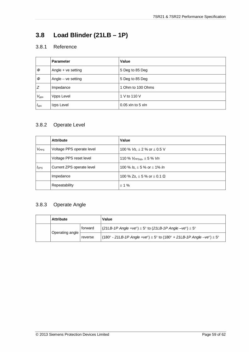
7SR21 & 7SR22 Performance Specification
© 2013 Siemens Protection Devices Limited Page 59 of 62
3.8 Load Blinder (21LB – 1P)
3.8.1 Reference
Parameter Value
Φ Angle + ve setting 5 Deg to 85 Deg
Φ Angle – ve setting 5 Deg to 85 Deg
Z Impedance 1 Ohm to 100 Ohms
Vpps Vpps Level 1 V to 110 V
Izps Izps Level 0.05 xIn to 5 xIn
3.8.2 Operate Level
Attribute Value
VPPS Voltage PPS operate level 100 % Vs, ± 2 % or ± 0.5 V
Voltage PPS reset level 110 % VPPSop, ± 5 % Vn
IZPS Current ZPS operate level 100 % Is, ± 5 % or ± 1% In
Impedance 100 % Zs, ± 5 % or ± 0.1 Ω
Repeatability ± 1 %
3.8.3 Operate Angle
Attribute Value
Operating angleforward (21LB-1P Angle +ve°) ± 5° to (21LB-1P Angle –ve°) ± 5°
reverse (180° - 21LB-1P Angle +ve°) ± 5° to (180° + 21LB-1P Angle –ve°) ± 5°

7SR21 & 7SR22 Performance Specification
Page 60 of 62 © 2013 Siemens Protection Devices Limited
Section 4: Control Functions4.1 Check Synchronising
4.1.1 ReferenceParameter Value
Vnom Nominal Voltage 40-160 V
fn Nominal Frequency 50/60 Hz
Vlive Live Setting 10 % - 150 %
Vdead Dead Setting 10 % - 150 %
Vsl Line Voltage Setting 10 % - 150 %
Vsb Bus Voltage Setting 10 % - 150 %
Vdiff Voltage Differential Setting 5 % - 95 %
Θcs CS Angle 1 – 90 º
Θss SS Angle 1 – 90 º
fcoz COZ Slip 30 mHz – 250 mHz
fcs CS Slip Freq 20 mHz – 250 mHz
fss SS Slip Freq 10 mHz – 250 mHz
tcs CS Timer 0-100 s
tss SS Timer 0-1 s
fsps Split Slip 20 mHz – 250 mHz
tdlc/tdbc DLC/DBC Delays 0-60 s
tcw Sync Close Window 1 s – 1200 s
4.1.2 Live/Dead Line/Bus Detector ElementsAttribute Value
Vlive,act Live operate level 100 % Vlive, ± 1 % Vn
Live reset level Vdead,act, ± 1 % Vn
Vdead,act Dead operate level 100 % Vdead, ± 1 % Vn
Dead reset level Vlive,act, ± 1 % Vn
Repeatability ± 1 %
Variation-10 °C to +55 °C £ 5 %
fnom ± 5 % £ 1 %

7SR21 & 7SR22 Performance Specification
© 2013 Siemens Protection Devices Limited Page 61 of 62
4.1.3 Line and Bus Undervoltage ElementsAttribute Value
Vline Operate level 100 % Vsl, ± 1 % Vn
Reset level £ Vline + 4 %
Vbus Operate level 100 % Vsb, ± 1 % Vn
Reset level £ Vbus + 4 %
Repeatability ± 1 %
Variation-10 °C to +55 °C £ 5 %
fnom ± 5 % £ 1 %
4.1.4 Voltage DifferenceAttribute Value
Vop Operate level 100 % Vdiff, ± 1 % Vn
Reset level ³ Vop – 4 %
Repeatability ± 2 %
4.1.5 General Autoreclose TimersAttribute Value
tbasic Element basic operate time 20 ms ± 20 ms
top tdlc/tdbc/tcw top + tbasic ± 1%
Repeatability ± 20 ms
4.1.6 CS/SS/COZ Line and Bus Phase Angle DifferenceAttribute Value
qop Operate angle qdiff, ± 1 º
Reset angle qop, ± 1 º
Repeatability ± 1 º
4.1.7 CS/SS/COZ Slip FrequencyAttribute Value
fop Operate frequency fslip, ± 10 mHz
Reset frequency fop, - 10 mHz
Repeatability ± 10 mHz
4.1.8 CS/SS TimerAttribute Value
top Operate time ± 1 º, + 20 msNote: minimum synchronising time following restoration of voltage from a dead condition is 320 ms.

7SR21 & 7SR22 Performance Specification
Page 62 of 62 © 2013 Siemens Protection Devices Limited
4.1.9 Split Angle DetectorAttribute Value
qop Operate angle qsplit, ± 1 °
4.1.10 Split Slip Frequency DetectorAttribute Value
fop Operate frequency fslip, ± 10 mHz
Reset frequency fop, - 10 mHz
Repeatability ± 10 mHz
4.2 Live/Dead
4.2.1 ReferenceParameter Value
Vs Setting (ABC side) 5, 5.5…200 VVs Setting (XYZ side) 5, 5.5…120 V
4.2.2 Live/Dead Detector ElementsAttribute Value
Vlive,act Live operate level 100 % Vlive, ± 1 % Vn
Live reset level Vdead,act, ± 1 % Vn
Vdead,act Dead operate level 100 % Vdead, ± 1 % Vn
Dead reset level Vlive,act, ± 1 % Vn
Repeatability ± 1 %
Variation-10 °C to +55 °C £ 5 %
fnom ± 5 % £ 1 %

Chapter 4 - 7SR210 · Data Communications Definitions
The copyright and other intellectual property rights in this document, and in any model or article produced from it(and including any registered or unregistered design rights) are the property of Siemens Protection Devices Limited.No part of this document shall be reproduced or modified or stored in another form, in any data retrieval system,without the permission of Siemens Protection Devices Limited, nor shall any model or article be reproduced from thisdocument unless Siemens Protection Devices Limited consent.
While the information and guidance given in this document is believed to be correct, no liability shall be accepted forany loss or damage caused by any error or omission, whether such error or omission is the result of negligence orany other cause. Any and all such liability is disclaimed.
© 2015 Siemens Protection Devices Limited
7SR210
7SR210x-1xAxx-0DA0Non-Directional Overcurrent Relay
Document Release HistoryThis document is issue 2015/06. The list of revisions up to and including this issue is:
Date Description
2015/06 Added additional protocol datapoints for 60870-5-103, DNP3 and Modbus.
2014/05 Added additional protocol datapoints for 60870-5-103, DNP3 and Modbus.
2013/12 Added additional protocol datapoints for 60870-5-103, DNP3 and Modbus.
2012/10 Added additional protocol datapoints for 60870-5-103, DNP3 and Modbus.
2011/05 First issue
Software Revision HistoryFW# Date Aricle Number Description
R8a-7f 2015/06 2435H85008R8a-7f
Added Arc Flash Detector functionality, includingFast Overcurrent detection and SARC IEC 61850logical nodes.
Added Load Blinding functionality applied to PhaseOvercurrent elements
R7f-7d 2014/05 2435H85008R7f-7d DNP3 vulnerability.
R7e-7c 2013/12 2435H85008R7e-7c Unexpected Restart events added.
R7c-7b 2012/10 2435H85008R7c-7b
Introduced journaling file system.
Added 61850 logical nodes for CB Counters,metering, 50BF, 46BC, 81HBL2 and line check.
Added Line Check on non-AR devices.
Added 74CCS Close Circuit Supervision.
R7a-7a 2011/05 2435H85008R7a-7a First issue
Note the column FW# above contains a reference to the firmware revision. This reference is used within this document where features have beenadded to the firmware and are available from a particular revision, or are specific to certain revisions.

7SR210 Technical Manual
Chapter 4 - Page 2 of 90 © 2015 Siemens Protection Devices Limited
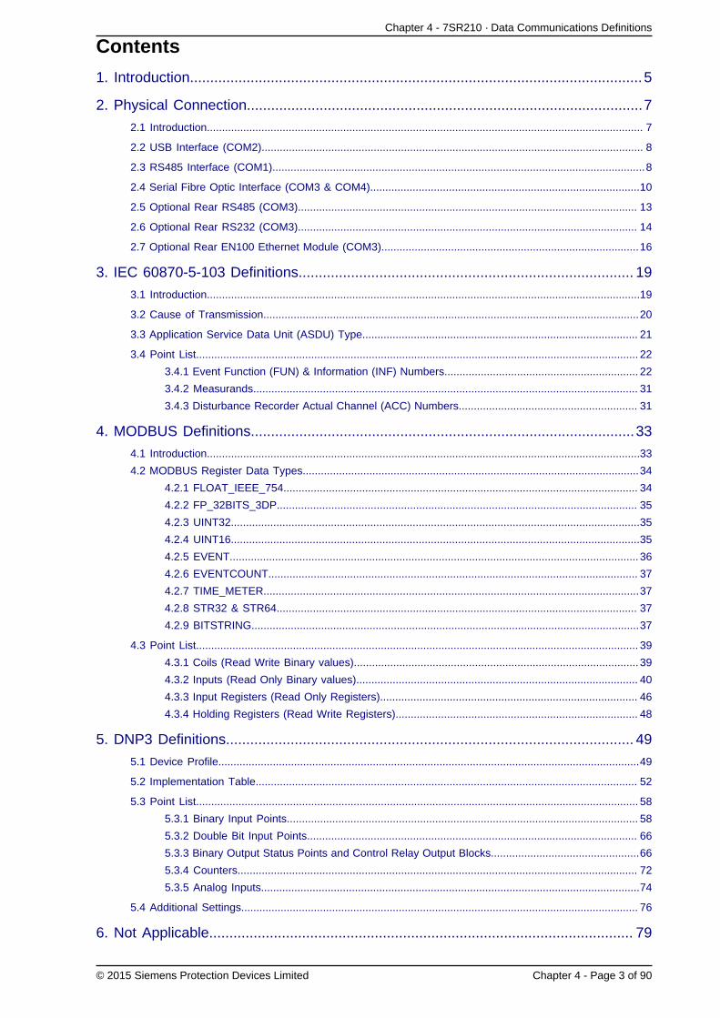
Chapter 4 - 7SR210 · Data Communications Definitions
© 2015 Siemens Protection Devices Limited Chapter 4 - Page 3 of 90
Contents
1. Introduction................................................................................................................ 5
2. Physical Connection..................................................................................................7
2.1 Introduction................................................................................................................................................ 7
2.2 USB Interface (COM2).............................................................................................................................. 8
2.3 RS485 Interface (COM1)...........................................................................................................................8
2.4 Serial Fibre Optic Interface (COM3 & COM4).........................................................................................10
2.5 Optional Rear RS485 (COM3)................................................................................................................ 13
2.6 Optional Rear RS232 (COM3)................................................................................................................ 14
2.7 Optional Rear EN100 Ethernet Module (COM3).....................................................................................16
3. IEC 60870-5-103 Definitions................................................................................... 19
3.1 Introduction...............................................................................................................................................19
3.2 Cause of Transmission............................................................................................................................20
3.3 Application Service Data Unit (ASDU) Type........................................................................................... 21
3.4 Point List.................................................................................................................................................. 22
3.4.1 Event Function (FUN) & Information (INF) Numbers................................................................ 22
3.4.2 Measurands............................................................................................................................... 31
3.4.3 Disturbance Recorder Actual Channel (ACC) Numbers........................................................... 31
4. MODBUS Definitions...............................................................................................33
4.1 Introduction...............................................................................................................................................33
4.2 MODBUS Register Data Types...............................................................................................................34
4.2.1 FLOAT_IEEE_754..................................................................................................................... 34
4.2.2 FP_32BITS_3DP....................................................................................................................... 35
4.2.3 UINT32.......................................................................................................................................35
4.2.4 UINT16.......................................................................................................................................35
4.2.5 EVENT....................................................................................................................................... 36
4.2.6 EVENTCOUNT.......................................................................................................................... 37
4.2.7 TIME_METER............................................................................................................................37
4.2.8 STR32 & STR64....................................................................................................................... 37
4.2.9 BITSTRING................................................................................................................................37
4.3 Point List.................................................................................................................................................. 39
4.3.1 Coils (Read Write Binary values).............................................................................................. 39
4.3.2 Inputs (Read Only Binary values)............................................................................................. 40
4.3.3 Input Registers (Read Only Registers)..................................................................................... 46
4.3.4 Holding Registers (Read Write Registers)................................................................................ 48
5. DNP3 Definitions..................................................................................................... 49
5.1 Device Profile...........................................................................................................................................49
5.2 Implementation Table.............................................................................................................................. 52
5.3 Point List.................................................................................................................................................. 58
5.3.1 Binary Input Points.................................................................................................................... 58
5.3.2 Double Bit Input Points............................................................................................................. 66
5.3.3 Binary Output Status Points and Control Relay Output Blocks.................................................66
5.3.4 Counters.................................................................................................................................... 72
5.3.5 Analog Inputs.............................................................................................................................74
5.4 Additional Settings................................................................................................................................... 76
6. Not Applicable......................................................................................................... 79

7SR210 Technical Manual
Chapter 4 - Page 4 of 90 © 2015 Siemens Protection Devices Limited
7. IEC61850 Protocol Support.................................................................................... 81
7.1 Introduction...............................................................................................................................................81
8. Serial Modems........................................................................................................ 83
8.1 Introduction...............................................................................................................................................83
8.2 Connecting a Modem to the Relay(s)..................................................................................................... 83
8.3 Setting the Remote Modem.....................................................................................................................83
8.4 Connecting to the Remote Modem......................................................................................................... 83
9. Configuration........................................................................................................... 85
10. Glossary.................................................................................................................87
Appendix 1...................................................................................................................89
List of FiguresFig. 2-1 Communication to Front USB Port................................................................................................................8
Fig. 2-2 Communication to Multiple Devices using RS485 (Standard Port)............................................................. 10
Fig. 2-3 Communication to Multiple Devices using Fibre-optic Ring Network.......................................................... 13
Fig. 2-4 Communication to Multiple Devices from Control System and Laptop using Fibre-optic Star Network........13
Fig. 2-5 Additional (Optional) Rear RS485 + IRIG-B Connection to a PC............................................................... 14
Fig. 2-6 Additional (Optional) Rear RS232 + IRIG-B Connection to a PC............................................................... 15
Fig. 2-7 RS232 Data Comms Pin Connections........................................................................................................ 15
Fig. 2-8 EN100 Ethernet Module.............................................................................................................................. 17
Fig. A1 Operating Mode Table................................................................................................................................. 89

Chapter 4 - 7SR210 · Data Communications Definitions
© 2015 Siemens Protection Devices Limited Chapter 4 - Page 5 of 90
1. Introduction
This section describes how to use the Communication Interface with a control system or interrogating computer.
The interface is compatible with control and automation systems using industry standard communications protocolsDNP3 , IEC 60870-5-103 , IEC 61850 and MODBUS-RTU. Note, not all protocols are available on all devices.
Reydisp Evolution or Reydisp Manager Software is available, for computers running Microsoft Windows™, to connectto devices to provide operational information, post-fault analysis, setting interrogation and editing facilities etc.Configuration software can be downloaded from our website http://www.siemens.com/energy.
This section specifies connection details and lists the information available through the individual protocols.

7SR210 Technical Manual
Chapter 4 - Page 6 of 90 © 2015 Siemens Protection Devices Limited

Chapter 4 - 7SR210 · Data Communications Definitions
© 2015 Siemens Protection Devices Limited Chapter 4 - Page 7 of 90
2. Physical Connection2.1 Introduction
The relay provides one “Front” USB communication interface (Com2) located on the fascia and one RS485 (Com1)located on the “Rear” as standard. An additional module may be fitted as an ordering option to provide extra rearserial port(s) or two Ethernet channels. Modules are available for serial fibre optic, RS232 and RS485. These modulesprovide one (Com3) or two (Com3 and Com4) additional ports. The optional EN100 Ethernet module, available inoptical and electrical versions, supports the IEC 61850 protocol and Reydisp access through the network (LAN port)interface.
A detailed description of the ports is given below.
COM1-RS485: This port can be used for IEC60870-5-103, MODBUS-RTU or DNP3 communications toa substation SCADA or integrated control system or for engineer remote access. Thisport can also be used for connection to Reydisp software.
COM2-USB: This port is used for IEC60870-5-103 (default setting) communication with the Reydispsoftware.
An ASCII protocol is also available through this port, the main use of this protocol is toallow the Relay firmware to be updated via the front connection.
MODBUS-RTU or the optional DNP3 protocols are also available.
COM3: Where fitted, an additional rear serial fibre optic, RS232 or RS485 port.
This port can be used for IEC60870-5-103, MODBUS-RTU or DNP3 communications toa substation SCADA or integrated control system or for engineer remote access. Thisport can also be used for connection to Reydisp software.
COM4: As COM3.
COM3-LAN: When the Ethernet module is fitted, in addition to IEC61850 a LAN connection is providedto allow the Reydisp software to connect to the Relay via the network. This port onlysupports the IEC60870-5-103 protocol.
Any or all serial ports can be mapped to the IEC60870-5-103, DNP3 or MODBUS-RTU protocol at any one time,protocols available will depend upon relay model. The optional ethernet port uses IEC 61850 protocol and can alsoprovide an IEC 60870-5-103 protocol connection to Reydisp. Any port not required can be disabled by setting itsprotocol to OFF.
When connecting to Reydisp Evolution software the protocol for the relevant port should be set to IEC60870-5-103.

7SR210 Technical Manual
Chapter 4 - Page 8 of 90 © 2015 Siemens Protection Devices Limited
2.2 USB Interface (COM2)
The USB communication port is connected using a standard USB cable with a type B connection to the relay andtype A to the PC.
The PC will require a suitable USB driver to be installed; this will be carried out automatically when the Reydispsoftware is installed. When the Reydisp software is running with the USB cable connected to a device an additionalconnection is shown. Connections to these devices are not shown when they are not connected.
The USB communication interface on the relay is labelled Com 2 and its associated settings are located in the Datacommunications menu. When connecting to Reydisp using this connection the default settings can be used withoutthe need to first change any settings.
Access to the communication settings for the USB port is only available from the relay front fascia via the key padsetting menu COMMUNICATIONS MENU.
Setting Name Range/Options Default Setting Notes
COM2-USB
Protocol
OFF
IEC60870-5-103
MODBUS-RTU
ASCII
DNP3
IEC60870-5-103Reydispsoftware requiresIEC60870-5-103.
COM2-USB
Station
Address
0 - 254 for IEC60870-5-103
1 - 247 for Modbus RTU
0 - 65534 for DNP3.0
0
An address within therange of the relevantprotocol must begiven to identify therelay. Each relay in anetwork must have aunique address.
COM2-USB
Mode
Local
Local or Remote
Remote
LocalRefer to Appendix1, page 89, forfurther explanation
LocalEngineerAccess
USB Type A
USB Data Cable
USB Type Asocket on PC
USB Type B
Fig. 2-1 Communication to Front USB Port
2.3 RS485 Interface (COM1)

Chapter 4 - 7SR210 · Data Communications Definitions
© 2015 Siemens Protection Devices Limited Chapter 4 - Page 9 of 90
The 2-wire RS485 communication port is located on the rear of the relay and can be connected using a suitableRS485 120 Ohm screened twisted pair cable.
The RS485 electrical connection can be used in a single or multi-drop configuration. The RS485 master must supportand use the Auto Device Enable (ADE) feature. The last device in the connection must be terminated correctly inaccordance with the master device driving the connection. This can be done via the internal 120 ohm terminatingresistor, which can be connected between 14 (A) and 18 (B) by fitting an external wire loop between terminals 18and 20 on the power supply module.
The maximum number of relays that can be connected to the bus is 64.
The RS485 data comms link will be broken for that particular relay element if it is withdrawn from the case but thechain of communication to the other relays is maintained.
The following settings, on the COMMUNICATIONS MENU, must be configured when using the RS485 interface.
Setting Name Range/Options Default Setting Notes
COM1-RS485
Protocol
OFF
IEC60870-5-103
MODBUS-RTU
DNP3
IEC60870-5-103
The protocol usedto communicate onthe standard RS485connection.
COM1-RS485
Station
Address
0 - 254 for IEC60870-5-103
1 - 247 for Modbus RTU
0 - 65534 for DNP3.0
0
An address within therange of the relevantprotocol must begiven to identify therelay. Each relay in anetwork must have aunique address.
COM1-RS485
Baud Rate
75 110 150 300
600 1200 2400 4800
9600 19200 38400
19200
The baud rate seton all of the relaysconnected to thecontrol system mustbe the same as theone set on the masterdevice.
COM1-RS485
Parity
NONE
ODD
EVEN
EVEN
The parity set onall of the relaysconnected to thecontrol system mustbe the same and inaccordance with themaster device.
COM1-RS485
Mode
Local
Local or Remote
Remote
RemoteRefer to Appendix1, page 89, forfurther explanation

7SR210 Technical Manual
Chapter 4 - Page 10 of 90 © 2015 Siemens Protection Devices Limited
To Control System 14
161820
RS485 Screened twisted pair
Rear terminals
141618
141618
RS485 Screened twisted pair
Rear terminals
Ext Wire loop (terminating
resistance) added where permanent drive from master station available
+ve
RS485
GN
D
-ve
Ter
m.
14 16 18 20
+ve
RS485
GN
D
-ve
Ter
m.
14 16 18 20
+ve
RS485
GN
D
-ve
Ter
m.
14 16 18 20
RS 485 Twisted pair Cable
To Control System
Fig. 2-2 Communication to Multiple Devices using RS485 (Standard Port)
2.4 Serial Fibre Optic Interface (COM3 & COM4)
When connecting via the optional fibre optic interface the selection of fibre-optic cable is important. Fibres must beterminated with ST™ (BFOC/2.5) connectors.
The recommended type is 62.5/125µm glass fibre. Communication distances over 1 km are achievable using thistype of fibre.
A budget loss calculation should be made for all installations. The following table gives the launch power and receiversensitivity of each of the fibre optic communication ports on the Relay when used with specific fibre optic types.
Tx Launch Power (dB) RX Receive Sensitivity (dB)Fibre Type
Min Max Min Max
62.5/125µm -11.7 -15.7 -24 -9.2
1mm Polymer -6.4 -10.4 -24 -9.2
200µm PCS -2.8 -6.8 -24 -9.2
Factors to be considered when calculating fibre-optic transmission distances:
• Transmitter launch power.
• Attenuation, based on light frequency, fibre material and fibre diameter. (Consult fibremanufacturers' data for actual values of fibre attenuation).
• Number of intermediate connectors and splices. Fibre cables are supplied on reels offinite length which may necessitate additional jointing. Typical losses at connectors are0.5-1.0dB each. This allows for normal age related deterioration. Typical losses at splicesare <0.3dB. (Consult fibre manufacturers' data for actual values).
• Receiver sensitivity. The light power at the receiver must be above the sensitivity of thereceiver in order that effective communication can occur.
• A 3dB safety margin is usually allowed after the budget calculation is performed.
Following installation and prior to putting into service the actual losses should be measured for each fibre using acalibrated light source and meter. Measured and calculated values can be compared.
The following table can be used to record budget calculations:

Chapter 4 - 7SR210 · Data Communications Definitions
© 2015 Siemens Protection Devices Limited Chapter 4 - Page 11 of 90
A Launch power dB
B Fibre Type
C Loss (dB/km) dB/km
D Length km
E Total fibre loss (CxD) dB
F No. of Splices
G Loss at each splice dB
H Total loss at splices (FxG) dB
I No. of connectors
J Loss per connector dB
K Total loss at connectors (IxJ) dB
L Total losses (E+H+K) dB
M Receive power budget (A-L) dB
N Safety Margin dB
O Device Receive Sensitivity dB
The following settings, on the COMMUNICATIONS MENU, must be configured when using the fibre Optic Com3interface.
Setting Name Range/Options Default Setting Notes
COM3
Protocol
OFF
IEC60870-5-103
MODBUS-RTU
DNP3
IEC60870-5-103
The protocol usedto communicate onthe standard RS485connection.
COM3
Station
Address
0 - 254 for IEC60870-5-103
1 - 247 for Modbus RTU
0 - 65534 for DNP3.0
0
An address within therange of the relevantprotocol must begiven to identify therelay. Each relay in anetwork must have aunique address.
COM3
Baud Rate
75 110 150 300
600 1200 2400 4800
9600 19200 38400
57600 115200
19200
The baud rate seton all of the relaysconnected to thecontrol system mustbe the same as theone set on the masterdevice.
COM3
Parity
NONE
ODD
EVEN
EVEN
The parity set onall of the relaysconnected to thecontrol system mustbe the same and inaccordance with themaster device.
COM3
Line Idle
LIGHT ON
LIGHT OFFLIGHT OFF
Sets the fibre opticline idle state.
COM3
Data Echo#1
ON
OFFOFF
Set to ON whenrelays are connectedin a fibre-optic ringconfiguration.
COM3
Mode
Local
Local or Remote
Remote
RemoteRefer to Appendix1, page 89, forfurther explanation
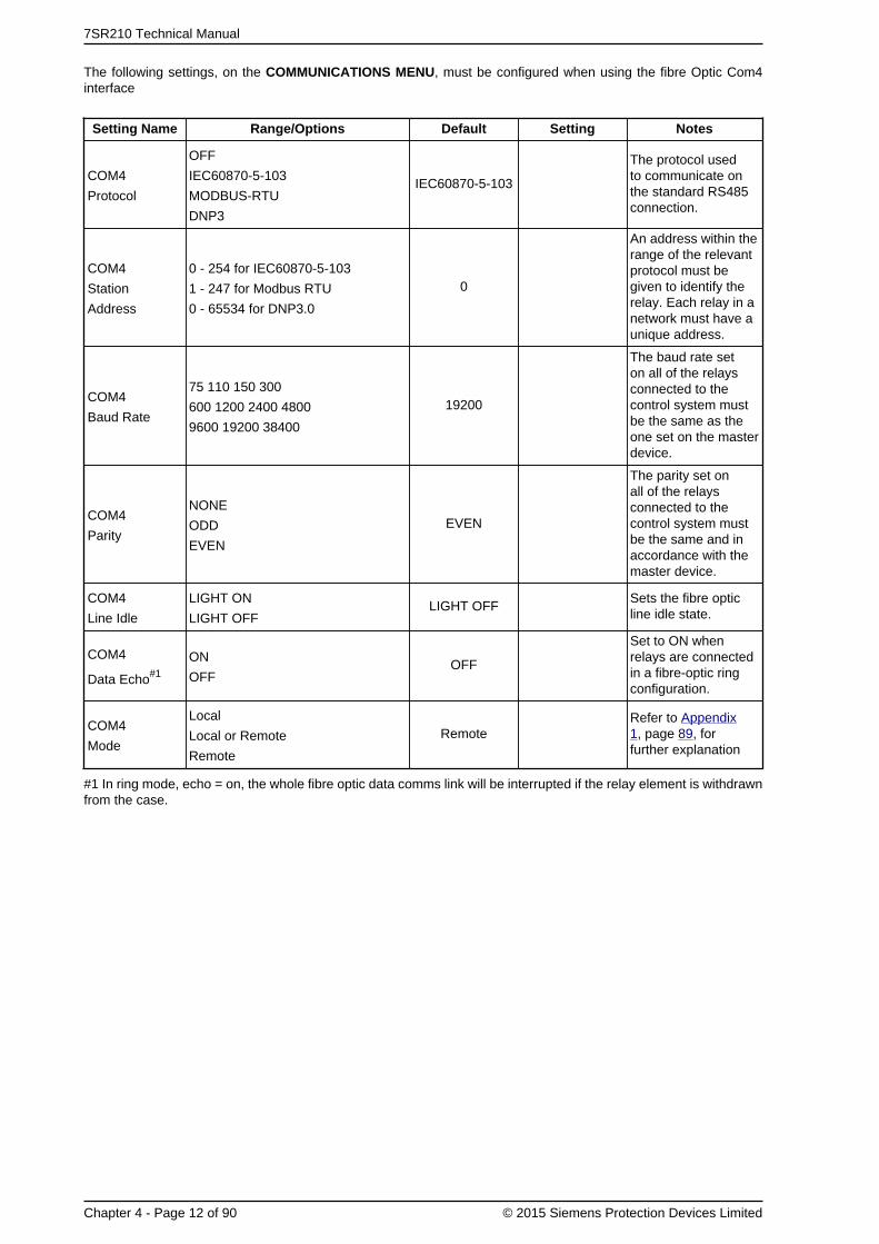
7SR210 Technical Manual
Chapter 4 - Page 12 of 90 © 2015 Siemens Protection Devices Limited
The following settings, on the COMMUNICATIONS MENU, must be configured when using the fibre Optic Com4interface
Setting Name Range/Options Default Setting Notes
COM4
Protocol
OFF
IEC60870-5-103
MODBUS-RTU
DNP3
IEC60870-5-103
The protocol usedto communicate onthe standard RS485connection.
COM4
Station
Address
0 - 254 for IEC60870-5-103
1 - 247 for Modbus RTU
0 - 65534 for DNP3.0
0
An address within therange of the relevantprotocol must begiven to identify therelay. Each relay in anetwork must have aunique address.
COM4
Baud Rate
75 110 150 300
600 1200 2400 4800
9600 19200 38400
19200
The baud rate seton all of the relaysconnected to thecontrol system mustbe the same as theone set on the masterdevice.
COM4
Parity
NONE
ODD
EVEN
EVEN
The parity set onall of the relaysconnected to thecontrol system mustbe the same and inaccordance with themaster device.
COM4
Line Idle
LIGHT ON
LIGHT OFFLIGHT OFF
Sets the fibre opticline idle state.
COM4
Data Echo#1
ON
OFFOFF
Set to ON whenrelays are connectedin a fibre-optic ringconfiguration.
COM4
Mode
Local
Local or Remote
Remote
RemoteRefer to Appendix1, page 89, forfurther explanation
#1 In ring mode, echo = on, the whole fibre optic data comms link will be interrupted if the relay element is withdrawnfrom the case.

Chapter 4 - 7SR210 · Data Communications Definitions
© 2015 Siemens Protection Devices Limited Chapter 4 - Page 13 of 90
RS232 to Fibre Optic Converter
Tx
Rx Tx
Rx
62.5/125µm fibre optic with ST connectors
Tx
Rx
Tx
Rx
Computer or Control System
USB or 9 pin maleD connector
RS232 straightthrough cable
25 pin male D connector
Fig. 2-3 Communication to Multiple Devices using Fibre-optic Ring Network
Computer or Control System
7SG24 Sigma 1
Tx
Rx Tx
Rx
62.5/125µm fibre optic with ST connectors
Tx
Rx
Tx
Rx
Tx
Rx
Tx
Rx
Tx
Rx
Tx
RxMaster
To Control System
USB or 9 pin maleD connector
RS232 straightthrough cable
25 pin male D connector
Fig. 2-4 Communication to Multiple Devices from Control System and Laptop using Fibre-optic Star Network
2.5 Optional Rear RS485 (COM3)
The following settings, on the COMMUNICATIONS MENU, must be configured when using the electrical 2-wire RS485Com3 interface.

7SR210 Technical Manual
Chapter 4 - Page 14 of 90 © 2015 Siemens Protection Devices Limited
Setting Name Range/Options Default Setting Notes
COM3
Protocol
OFF
IEC60870-5-103
MODBUS-RTU
DNP3
IEC60870-5-103
The protocol usedto communicate onthe standard RS485connection.
COM3
Station
Address
0 - 254 for IEC60870-5-103
1 - 247 for Modbus RTU
0 - 65534 for DNP3.0
0
An address within therange of the relevantprotocol must begiven to identify therelay. Each relay in anetwork must have aunique address.
COM3
Baud Rate
75 110 150 300
600 1200 2400 4800
9600 19200 38400
57600 115200
19200
The baud rate seton all of the relaysconnected to thecontrol system mustbe the same as theone set on the masterdevice.
COM3
Parity
NONE
ODD
EVEN
EVEN
The parity set onall of the relaysconnected to thecontrol system mustbe the same and inaccordance with themaster device.
COM3
Line Idle
LIGHT ON
LIGHT OFFLIGHT OFF LIGHT OFF
Not applicable forRS 485 or RS 232option, set to OFF.
COM3
Data Echo#1
ON
OFFOFF OFF
Not applicable forRS 485 or RS 232option, set to OFF.
COM3
Mode
Local
Local or Remote
Remote
RemoteRefer to Appendix1, page 89, forfurther explanation
COMMS MODULE
IRIG-B
COM3
GND
TERM
B
A
Laptop computerRS232 straight through cable
USB or 9 pin male D connector
RS485 Screened twisted pair
7SR24
Fig. 2-5 Additional (Optional) Rear RS485 + IRIG-B Connection to a PC
2.6 Optional Rear RS232 (COM3)
The following settings, on the COMMUNICATIONS MENU, must be configured when using the electrical RS232Com3 interface.

Chapter 4 - 7SR210 · Data Communications Definitions
© 2015 Siemens Protection Devices Limited Chapter 4 - Page 15 of 90
Setting Name Range/Options Default Setting Notes
COM3
Protocol
OFF
IEC60870-5-103
MODBUS-RTU
DNP3
IEC60870-5-103
The protocol usedto communicate onthe standard RS485connection.
COM3
Station
Address
0 - 254 for IEC60870-5-103
1 - 247 for Modbus RTU
0 - 65534 for DNP3.0
0
An address within therange of the relevantprotocol must begiven to identify therelay. Each relay in anetwork must have aunique address.
COM3
Baud Rate
75 110 150 300
600 1200 2400 4800
9600 19200 38400
57600 115200
19200
The baud rate seton all of the relaysconnected to thecontrol system mustbe the same as theone set on the masterdevice.
COM3
Parity
NONE
ODD
EVEN
EVEN
The parity set onall of the relaysconnected to thecontrol system mustbe the same and inaccordance with themaster device.
COM3
Line Idle
LIGHT ON
LIGHT OFFLIGHT OFF LIGHT OFF
Not applicable forRS 485 or RS 232option, set to OFF.
COM3
Data Echo#1
ON
OFFOFF OFF
Not applicable forRS 485 or RS 232option, set to OFF.
COM3
Mode
Local
Local or Remote
Remote
RemoteRefer to Appendix1, page 89, forfurther explanation
USB or 9 pin male D connector
RS232 cross-over cable or RS232 to USB converter cableLaptop computer
COMMS MODULE
IRIG-B
COM3
7SR24
Fig. 2-6 Additional (Optional) Rear RS232 + IRIG-B Connection to a PC
Pin Relay Function
1 Not Connected
2 Receive Data (RXD)
3 Transmit Data (TXD)

7SR210 Technical Manual
Chapter 4 - Page 16 of 90 © 2015 Siemens Protection Devices Limited
Pin Relay Function
4 Output Supply +5V 50mA
5 Signal Ground (GND)
6 Output Supply +5V 50mA
7 Linked to 8 (volts free)
8 Linked to 7 (volts free)
9 Output Supply +5V 50mA
Fig. 2-7 RS232 Data Comms Pin Connections
2.7 Optional Rear EN100 Ethernet Module (COM3)
The optional ethernet interface is primarily provided for support of IEC 61850 Protocol. Support for IEC 60870-5-103is also provided over this interface to allow connection with Reydisp Evolution and Reydisp Manager Software forinterrogation, editing and download of relay settings and other data. Ordering options are available with two RJ45electrical connectors or with two duplex LC fibre optic connectors.
Setting Name Range/Options Default Setting Notes
LAN
Protocol
OFF
IEC60870-5-103IEC60870-5-103
Sets the protocolused to communicateon the LAN port.
If this setting is set to off, access to relay data using Reydisp Evolution and Reydisp Manager Software via theEthernet interface is not available.
Connections to the optional EN100 Ethernet module are made on the rear underside of the relay.
Connections are made to either RJ45 sockets (electrical) or Duplex LC (fibre optic) connectors. Fibre cables shouldbe 62.5/125µm (or 50/125µm) multimode with LC connectors.
The two types of EN100 module work slightly differently. The optical version contains an Ethernet switch to controlthe two channels. The switch will manage data from either channel as an Ethernet switch would in a network. Theelectrical version connects through one channel until it detects a break in the data traffic. After a delay it will swap tothe other channel to try and re-establish communication. Either method can be thought of as providing for redundancy.
While a 61850 session is established, an operator can simultaneously connect to the device via Reydisp Evolutionor a web browser through the EN100 module.
Configuration of 61850 communication is via the Reydisp Manager software package.

Chapter 4 - 7SR210 · Data Communications Definitions
© 2015 Siemens Protection Devices Limited Chapter 4 - Page 17 of 90
LED yellow
LED green
LED yellow
LED green
Ch 1 Ch 2
Ethernet – EN100-E
EN100 Module – RJ45 Interface
Ethernet – EN100-O
Ch 1 Ch 2
EN100 Module – Duplex-LC Interface
Green LED (Physical Link)Off – No linkOn – Link present
Yellow LED (Activity)Off – No trafficOn/flashing - Traffic
Fig. 2-8 EN100 Ethernet Module

7SR210 Technical Manual
Chapter 4 - Page 18 of 90 © 2015 Siemens Protection Devices Limited

Chapter 4 - 7SR210 · Data Communications Definitions
© 2015 Siemens Protection Devices Limited Chapter 4 - Page 19 of 90
3. IEC 60870-5-103 Definitions3.1 Introduction
This section describes the IEC 60870-5-103 protocol implementation in the relays. This protocol is used for thecommunication with Reydisp software and can also be used for communication with a suitable control system.The control system or local PC acts as the master in the system with the relay operating as a slave respondingto the master's commands. The implementation provides event information, time synchronising, commands andmeasurands and also supports the transfer of disturbance records.
This protocol can be set to use any or all of the relays hardware interfaces (USB, Fibre Optic, RS232, RS485 andEthernet) and is the standard protocol used by the USB port. The relay can communicate simultaneously on all portsregardless of protocol used.
The Station Address of the port being used must be set to a suitable address within the range 0 - 254 to enablecommunication. This can be set by the Communications Menu : COM n-xxxxx Station Address setting.

7SR210 Technical Manual
Chapter 4 - Page 20 of 90 © 2015 Siemens Protection Devices Limited
3.2 Cause of Transmission
The cause of transmission (COT) column of the “Information Number and Function” table lists possible causes oftransmission for these frames. The following abbreviations are used:
Abbreviation Description
SE spontaneous event
T test mode
GI general interrogation
Loc local operation
Rem remote operation
Ack command acknowledge
Nak Negative command acknowledge
Note: Events listing a GI cause of transmission can be raised and cleared; other events are raised only.

Chapter 4 - 7SR210 · Data Communications Definitions
© 2015 Siemens Protection Devices Limited Chapter 4 - Page 21 of 90
3.3 Application Service Data Unit (ASDU) Type
The Application Service Data Unit (ASDU) column of the “Information Number and Function” table lists the possibleASDUs returned for a point.
ASDU # Description
1 Time tagged message (monitor direction)
2 Time tagged message (relative time) (monitor direction)
3.1 Measurands I
4 Time-tagged measurands with relative time
5 Identification message
6 Time synchronisation
7 General Interrogation Initialization
9 Measurands II
20 General command

7SR210 Technical Manual
Chapter 4 - Page 22 of 90 © 2015 Siemens Protection Devices Limited
3.4 Point List
The following sub-sections contain tables listing the data points available via the IEC60870-5-103 protocol.
The information shown below is the default configuration. This can be modified using the CommunicationsConfiguration Editor tool, refer section 9 for details.
3.4.1 Event Function (FUN) & Information (INF) Numbers
The following Event EVT and INF numbers apply to this device.
FW# FUN INF Description ASDU COT
1 SE, GI60 4 Remote Mode
20 Ack, Nak
1 SE, GI60 5 Out Of Service Mode
20 Ack, Nak
1 SE, GI60 6 Local Mode
20 Ack, Nak
1 SE, GI60 7 Local & Remote
20 Ack, Nak
60 12 Control Received 1 SE
60 13 Command Received 1 SE
60 128 Cold Start 1 SE
60 129 Warm Start 1 SE
60 130 Re-Start 1 SE
R7b-7c 60 131 Expected Restart 1 SE, GI
R7b-7c 60 132 Unexpected Restart 1 SE, GI
1 SER7b-7c 60 133 Reset Start Count
20 Ack, Nak
60 135 Trigger Storage 1 SE
60 136 Clear Waveform Records 1 SE
60 137 Clear Fault Records 1 SE
60 138 Clear Event Records 1 SE
1 SE60 140 Demand metering reset
20 Ack, Nak
60 170 General Alarm 1 1 SE, GI
60 171 General Alarm 2 1 SE, GI
60 172 General Alarm 3 1 SE, GI
60 173 General Alarm 4 1 SE, GI
60 174 General Alarm 5 1 SE, GI
60 175 General Alarm 6 1 SE, GI
60 176 General Alarm 7 1 SE, GI
60 177 General Alarm 8 1 SE, GI
60 178 General Alarm 9 1 SE, GI
60 179 General Alarm 10 1 SE, GI
60 180 General Alarm 11 1 SE, GI
60 181 General Alarm 12 1 SE, GI
60 182 Quick Logic E1 1 SE, GI
60 183 Quick Logic E2 1 SE, GI
60 184 Quick Logic E3 1 SE, GI

Chapter 4 - 7SR210 · Data Communications Definitions
© 2015 Siemens Protection Devices Limited Chapter 4 - Page 23 of 90
FW# FUN INF Description ASDU COT
60 185 Quick Logic E4 1 SE, GI
60 186 Quick Logic E5 1 SE, GI
60 187 Quick Logic E6 1 SE, GI
60 188 Quick Logic E7 1 SE, GI
60 189 Quick Logic E8 1 SE, GI
60 190 Quick Logic E9 1 SE, GI
60 191 Quick Logic E10 1 SE, GI
60 192 Quick Logic E11 1 SE, GI
60 193 Quick Logic E12 1 SE, GI
60 194 Quick Logic E13 1 SE, GI
60 195 Quick Logic E14 1 SE, GI
60 196 Quick Logic E15 1 SE, GI
60 197 Quick Logic E16 1 SE, GI
60 214 Function Key 1 1 SE
60 215 Function Key 2 1 SE
60 216 Function Key 3 1 SE
60 217 Function Key 4 1 SE
60 218 Function Key 5 1 SE
60 219 Function Key 6 1 SE
R7b-7c 61 1 General Alarm 13 1 SE, GI
R7b-7c 61 2 General Alarm 14 1 SE, GI
R7b-7c 61 3 General Alarm 15 1 SE, GI
R7b-7c 61 4 General Alarm 16 1 SE, GI
R7b-7c 61 5 General Alarm 17 1 SE, GI
R7b-7c 61 6 General Alarm 18 1 SE, GI
R7b-7c 61 7 General Alarm 19 1 SE, GI
R7b-7c 61 8 General Alarm 20 1 SE, GI
70 5 Binary Input 5 1 SE, GI
70 6 Binary Input 6 1 SE, GI
70 7 Binary Input 7 1 SE, GI
70 8 Binary Input 8 1 SE, GI
70 9 Binary Input 9 1 SE, GI
70 10 Binary Input 10 1 SE, GI
70 11 Binary Input 11 1 SE, GI
70 12 Binary Input 12 1 SE, GI
70 13 Binary Input 13 1 SE, GI
70 14 Binary Input 14 1 SE, GI
70 15 Binary Input 15 1 SE, GI
70 16 Binary Input 16 1 SE, GI
70 17 Binary Input 17 1 SE, GI
70 18 Binary Input 18 1 SE, GI
70 19 Binary Input 19 1 SE, GI
R7b-7c 75 1 Virtual Input 1 1 SE, GI
R7b-7c 75 2 Virtual Input 2 1 SE, GI
R7b-7c 75 3 Virtual Input 3 1 SE, GI

7SR210 Technical Manual
Chapter 4 - Page 24 of 90 © 2015 Siemens Protection Devices Limited
FW# FUN INF Description ASDU COT
R7b-7c 75 4 Virtual Input 4 1 SE, GI
R7b-7c 75 5 Virtual Input 5 1 SE, GI
R7b-7c 75 6 Virtual Input 6 1 SE, GI
R7b-7c 75 7 Virtual Input 7 1 SE, GI
R7b-7c 75 8 Virtual Input 8 1 SE, GI
R7b-7c 75 9 Virtual Input 9 1 SE, GI
R7b-7c 75 10 Virtual Input 10 1 SE, GI
R7b-7c 75 11 Virtual Input 11 1 SE, GI
R7b-7c 75 12 Virtual Input 12 1 SE, GI
R7b-7c 75 13 Virtual Input 13 1 SE, GI
R7b-7c 75 14 Virtual Input 14 1 SE, GI
R7b-7c 75 15 Virtual Input 15 1 SE, GI
R7b-7c 75 16 Virtual Input 16 1 SE, GI
1 SE, GI80 1 Binary Output 1
20 Ack, Nak
1 SE, GI80 2 Binary Output 2
20 Ack, Nak
1 SE, GI80 3 Binary Output 3
20 Ack, Nak
1 SE, GI80 4 Binary Output 4
20 Ack, Nak
1 SE, GI80 5 Binary Output 5
20 Ack, Nak
1 SE, GI80 6 Binary Output 6
20 Ack, Nak
1 SE, GI80 7 Binary Output 7
20 Ack, Nak
1 SE, GI80 8 Binary Output 8
20 Ack, Nak
1 SE, GI80 9 Binary Output 9
20 Ack, Nak
1 SE, GI80 10 Binary Output 10
20 Ack, Nak
1 SE, GI80 11 Binary Output 11
20 Ack, Nak
1 SE, GI80 12 Binary Output 12
20 Ack, Nak
1 SE, GI80 13 Binary Output 13
20 Ack, Nak
1 SE, GI80 14 Binary Output 14
20 Ack, Nak
1 SE, GI80 15 Binary Output 15
20 Ack, Nak
1 SE, GI80 16 Binary Output 16
20 Ack, Nak
R7b-7c 90 1 LED 1 1 SE, GI

Chapter 4 - 7SR210 · Data Communications Definitions
© 2015 Siemens Protection Devices Limited Chapter 4 - Page 25 of 90
FW# FUN INF Description ASDU COT
R7b-7c 90 2 LED 2 1 SE, GI
R7b-7c 90 3 LED 3 1 SE, GI
R7b-7c 90 4 LED 4 1 SE, GI
R7b-7c 90 5 LED 5 1 SE, GI
R7b-7c 90 6 LED 6 1 SE, GI
R7b-7c 90 7 LED 7 1 SE, GI
R7b-7c 90 8 LED 8 1 SE, GI
R7b-7c 90 9 LED 9 1 SE, GI
R7b-7c 90 10 LED 10 1 SE, GI
R7b-7c 90 11 LED 11 1 SE, GI
R7b-7c 90 12 LED 12 1 SE, GI
R7b-7c 90 13 LED 13 1 SE, GI
R7b-7c 90 14 LED 14 1 SE, GI
R7b-7c 90 15 LED 15 1 SE, GI
R7b-7c 90 16 LED 16 1 SE, GI
R7b-7c 91 1 LED PU 1 1 SE, GI
R7b-7c 91 2 LED PU 2 1 SE, GI
R7b-7c 91 3 LED PU 3 1 SE, GI
R7b-7c 91 4 LED PU 4 1 SE, GI
R7b-7c 91 5 LED PU 5 1 SE, GI
R7b-7c 91 6 LED PU 6 1 SE, GI
R7b-7c 91 7 LED PU 7 1 SE, GI
R7b-7c 91 8 LED PU 8 1 SE, GI
R7b-7c 91 9 LED PU 9 1 SE, GI
R7b-7c 91 10 LED PU 10 1 SE, GI
R7b-7c 91 11 LED PU 11 1 SE, GI
R7b-7c 91 12 LED PU 12 1 SE, GI
R7b-7c 91 13 LED PU 13 1 SE, GI
R7b-7c 91 14 LED PU 14 1 SE, GI
R7b-7c 91 15 LED PU 15 1 SE, GI
R7b-7c 91 16 LED PU 16 1 SE, GI
160 2 Reset FCB 5 SE
160 3 Reset CU 5 SE
160 4 Start/Restart 5 SE
160 5 Power On 1 SE, GI
1 SE, GI160 16 Auto-reclose active
20 Ack, Nak
1 SE160 19 LED Reset
20 Ack, Nak
160 22 Settings changed 1 SE
160 23 Setting G1 selected 1 SE, GI

7SR210 Technical Manual
Chapter 4 - Page 26 of 90 © 2015 Siemens Protection Devices Limited
FW# FUN INF Description ASDU COT
20 Ack, Nak
1 SE, GI160 24 Setting G2 selected
20 Ack, Nak
1 SE, GI160 25 Setting G3 selected
20 Ack, Nak
1 SE, GI160 26 Setting G4 selected
20 Ack, Nak
160 27 Binary Input 1 1 SE, GI
160 28 Binary Input 2 1 SE, GI
160 29 Binary Input 3 1 SE, GI
160 30 Binary Input 4 1 SE, GI
160 36 Trip Circuit Fail 1 SE, GI
160 64 Start/Pick-up L1 2 SE, GI
160 65 Start/Pick-up L2 2 SE, GI
160 66 Start/Pick-up L3 2 SE, GI
160 67 Start/Pick-up N 2 SE, GI
160 68 General Trip 2 SE
160 69 Trip L1 2 SE
160 70 Trip L2 2 SE
160 71 Trip L3 2 SE
160 84 General Start/Pick-up 2 SE, GI
160 85 Breaker Failure 2 SE
160 90 Trip I> 2 SE
160 91 Trip I>> 2 SE
160 92 Trip In> 2 SE
160 93 Trip In>> 2 SE
160 128 CB on by auto reclose 1 SE
183 10 51-1 2 SE, GI
183 11 50-1 2 SE, GI
183 12 51N-1 2 SE, GI
183 13 50N-1 2 SE, GI
183 14 51G-1 2 SE, GI
183 15 50G-1 2 SE, GI
183 16 51-2 2 SE, GI
183 17 50-2 2 SE, GI
183 18 51N-2 2 SE, GI
183 19 50N-2 2 SE, GI
183 20 51G-2 2 SE, GI
183 21 50G-2 2 SE, GI
183 34 50BF Stage 2 2 SE, GI
183 35 49-Alarm 2 SE, GI
183 36 49-Trip 2 SE, GI
183 41 51SEF-1 2 SE, GI
183 42 50SEF-1 2 SE, GI
183 43 51SEF-2 2 SE, GI
183 44 50SEF-2 2 SE, GI
2 SE, GI183 49 SEF Out
20 Ack, Nak
183 50 46IT 2 SE, GI

Chapter 4 - 7SR210 · Data Communications Definitions
© 2015 Siemens Protection Devices Limited Chapter 4 - Page 27 of 90
FW# FUN INF Description ASDU COT
183 51 46DT 2 SE, GI
183 52 64H 2 SE, GI
2 SE, GI183 53 E/F Out
20 Ack, Nak
R7b-7c 183 56 50BF Stage 1 2 SE, GI
183 62 37-1 2 SE, GI
183 63 37-2 2 SE, GI
183 64 37G-1 2 SE, GI
183 65 37G-2 2 SE, GI
183 70 46BC 2 SE, GI
183 96 81HBL2 1 SE, GI
R7b-7c 183 100 CB Alarm 1 SE, GI
183 101 Trip Circuit Fail 1 2 SE, GI
183 102 Trip Circuit Fail 2 2 SE, GI
183 103 Trip Circuit Fail 3 2 SE, GI
1 SE, GI183 110 Setting G5 selected
20 Ack, Nak
1 SE, GI183 111 Setting G6 selected
20 Ack, Nak
1 SE, GI183 112 Setting G7 selected
20 Ack, Nak
1 SE, GI183 113 Setting G8 selected
20 Ack, Nak
183 114 Close CB Failed 1 SE, GI
183 115 Open CB Failed 1 SE, GI
183 116 Reclaim 1 SE, GI
183 117 Lockout 1 SE, GI
183 119 Successful DAR Close 1 SE
183 120 Successful Man Close 1 SE
1 SE, GI183 121 HotLine Working
20 Ack, Nak
1 SE, GI183 122 Inst Protection Out
20 Ack, Nak
183 123 CB Total Trip Count 1 SE, GI
183 124 CB Delta Trip Count 1 SE, GI
183 125 CB Count To AR Block 1 SE, GI
1 SE183 126 Reset CB Total Trip Count
20 Ack, Nak
1 SE183 127 Reset CB Delta Trip Count
20 Ack, Nak
1 SE183 128 Reset CB Count To AR Block
20 Ack, Nak
183 129 I^2t CB Wear 1 SE, GI
1 SE183 130 Reset I^2t CB Wear
20 Ack, Nak
183 131 79 AR In progress 1 SE, GI
183 132 CB Frequent Ops Count 1 SE, GI

7SR210 Technical Manual
Chapter 4 - Page 28 of 90 © 2015 Siemens Protection Devices Limited
FW# FUN INF Description ASDU COT
1 SE183 133 Reset CB Frequent Ops Count
20 Ack, Nak
R7b-7c 183 137 CB on by auto reclose 1 SE, GI
183 140 Cold Load Active 1 SE, GI
183 141 P/F Inst Protection Inhibited 1 SE, GI
183 142 E/F Inst Protection Inhibited 1 SE, GI
183 143 SEF Inst Protection Inhibited 1 SE, GI
183 144 Ext Inst Protection Inhibited 1 SE, GI
183 163 Trip Time Alarm 1 SE
183 164 Close Circuit Fail 1 2 SE, GI
183 165 Close Circuit Fail 2 2 SE, GI
183 166 Close Circuit Fail 3 2 SE, GI
183 167 Close Circuit Fail 2 SE, GI
183 171 60 CTS-I 2 SE, GI
183 181 CB Total Trip Count 4 SE
183 182 CB Delta Trip Count 4 SE
183 183 CB Count To AR Block 4 SE
183 184 CB Freq Ops Count 4 SE
R7b-7c 183 222 37-PhA 2 SE, GI
R7b-7c 183 223 37-PhB 2 SE, GI
R7b-7c 183 224 37-PhC 2 SE, GI
R7b-7c 183 231 50BF-PhA 2 SE, GI
R7b-7c 183 232 50BF-PhB 2 SE, GI
R7b-7c 183 233 50BF-PhC 2 SE, GI
R7b-7c 183 234 50BF-EF 2 SE, GI
R7b-7c 183 235 79 Last Trip Lockout 2 SE, GI
R7f-7d 183 237 CB DBI 1 SE, GI
R7f-7d 183 238 CB Travelling 1 SE, GI
R7e-7c 183 239 In Fault Current 4 SE
R7e-7c 183 240 Ia Fault Current 4 SE
R7e-7c 183 241 Ib Fault Current 4 SE
R7e-7c 183 242 Ic Fault Current 4 SE
R7e-7c 183 243 Ig Fault Current 4 SE
183 249 60 CTS-I-PhA 2 SE, GI
R7b-7c 183 250 60 CTS-I-PhB 2 SE, GI
R7b-7c 183 251 60 CTS-I-PhC 2 SE, GI
R7b-7c 183 252 Trip PhA 2 SE, GI
R7b-7c 183 253 Trip PhB 2 SE, GI
R7b-7c 183 254 Trip PhC 2 SE, GI
R7b-7c 185 9 CB Phase A Trip Count 4 SE
R7b-7c 185 10 CB Phase B Trip Count 4 SE
R7b-7c 185 11 CB Phase C Trip Count 4 SE
R7b-7c 185 12 CB E/F Trip Count 4 SE
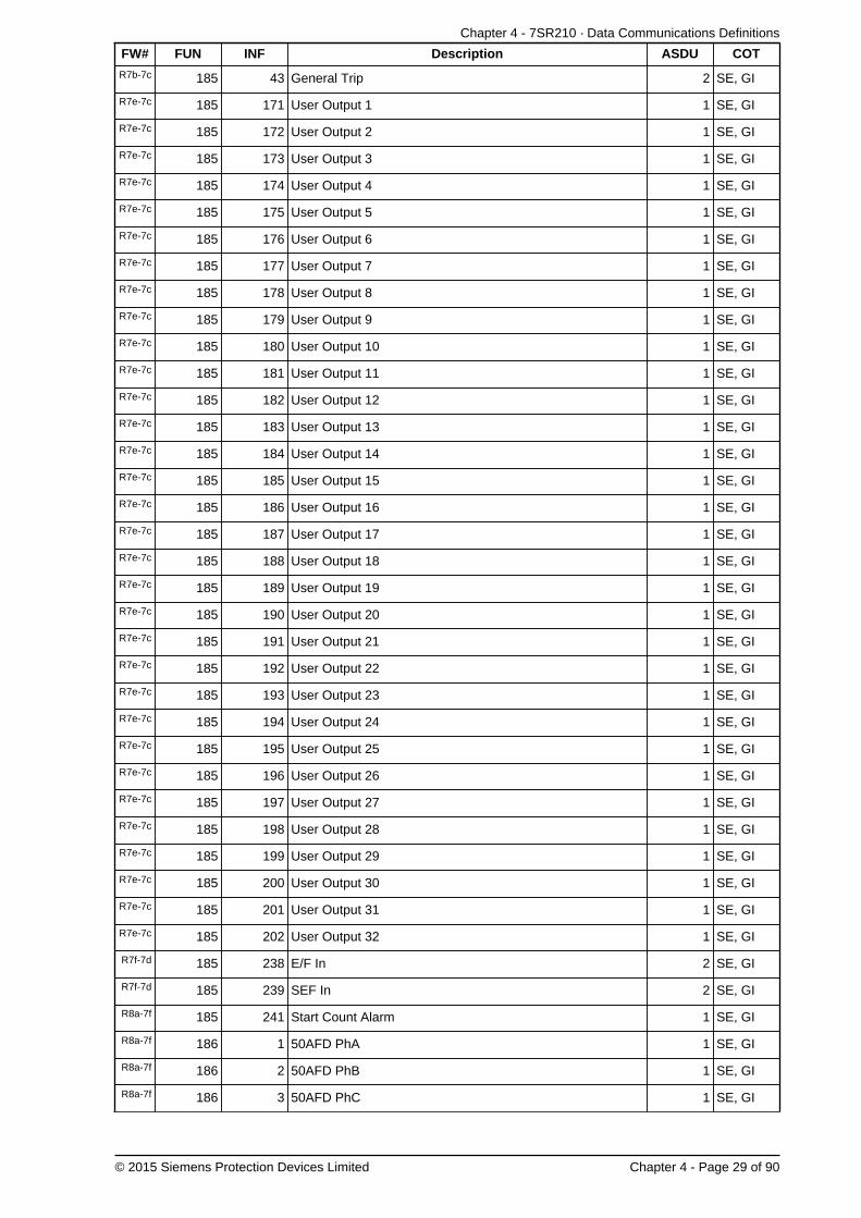
Chapter 4 - 7SR210 · Data Communications Definitions
© 2015 Siemens Protection Devices Limited Chapter 4 - Page 29 of 90
FW# FUN INF Description ASDU COT
R7b-7c 185 43 General Trip 2 SE, GI
R7e-7c 185 171 User Output 1 1 SE, GI
R7e-7c 185 172 User Output 2 1 SE, GI
R7e-7c 185 173 User Output 3 1 SE, GI
R7e-7c 185 174 User Output 4 1 SE, GI
R7e-7c 185 175 User Output 5 1 SE, GI
R7e-7c 185 176 User Output 6 1 SE, GI
R7e-7c 185 177 User Output 7 1 SE, GI
R7e-7c 185 178 User Output 8 1 SE, GI
R7e-7c 185 179 User Output 9 1 SE, GI
R7e-7c 185 180 User Output 10 1 SE, GI
R7e-7c 185 181 User Output 11 1 SE, GI
R7e-7c 185 182 User Output 12 1 SE, GI
R7e-7c 185 183 User Output 13 1 SE, GI
R7e-7c 185 184 User Output 14 1 SE, GI
R7e-7c 185 185 User Output 15 1 SE, GI
R7e-7c 185 186 User Output 16 1 SE, GI
R7e-7c 185 187 User Output 17 1 SE, GI
R7e-7c 185 188 User Output 18 1 SE, GI
R7e-7c 185 189 User Output 19 1 SE, GI
R7e-7c 185 190 User Output 20 1 SE, GI
R7e-7c 185 191 User Output 21 1 SE, GI
R7e-7c 185 192 User Output 22 1 SE, GI
R7e-7c 185 193 User Output 23 1 SE, GI
R7e-7c 185 194 User Output 24 1 SE, GI
R7e-7c 185 195 User Output 25 1 SE, GI
R7e-7c 185 196 User Output 26 1 SE, GI
R7e-7c 185 197 User Output 27 1 SE, GI
R7e-7c 185 198 User Output 28 1 SE, GI
R7e-7c 185 199 User Output 29 1 SE, GI
R7e-7c 185 200 User Output 30 1 SE, GI
R7e-7c 185 201 User Output 31 1 SE, GI
R7e-7c 185 202 User Output 32 1 SE, GI
R7f-7d 185 238 E/F In 2 SE, GI
R7f-7d 185 239 SEF In 2 SE, GI
R8a-7f 185 241 Start Count Alarm 1 SE, GI
R8a-7f 186 1 50AFD PhA 1 SE, GI
R8a-7f 186 2 50AFD PhB 1 SE, GI
R8a-7f 186 3 50AFD PhC 1 SE, GI

7SR210 Technical Manual
Chapter 4 - Page 30 of 90 © 2015 Siemens Protection Devices Limited
FW# FUN INF Description ASDU COT
R8a-7f 186 4 50AFD 1 SE, GI
R8a-7f 186 5 AFD Zone 1 Flash 1 SE, GI
R8a-7f 186 6 AFD Zone 1 1 SE, GI
R8a-7f 186 7 AFD Zone 2 Flash 1 SE, GI
R8a-7f 186 8 AFD Zone 2 1 SE, GI
R8a-7f 186 9 AFD Zone 3 Flash 1 SE, GI
R8a-7f 186 10 AFD Zone 3 1 SE, GI
R8a-7f 186 11 AFD Zone 4 Flash 1 SE, GI
R8a-7f 186 12 AFD Zone 4 1 SE, GI
R8a-7f 186 13 AFD Zone 5 Flash 1 SE, GI
R8a-7f 186 14 AFD Zone 5 1 SE, GI
R8a-7f 186 15 AFD Zone 6 Flash 1 SE, GI
R8a-7f 186 16 AFD Zone 6 1 SE, GI
R8a-7f 186 17 AFD Zone1 Count 4 SE
R8a-7f 186 18 AFD Zone2 Count 4 SE
R8a-7f 186 19 AFD Zone3 Count 4 SE
R8a-7f 186 20 AFD Zone4 Count 4 SE
R8a-7f 186 21 AFD Zone5 Count 4 SE
R8a-7f 186 22 AFD Zone6 Count 4 SE
1 SE200 1 CB 1
20 Ack, Nak
1 SE, GIR7b-7c 200 6 CB 1 Opened
20 Ack, Nak
1 SE, GIR7b-7c 200 7 CB 1 Closed
20 Ack, Nak
1 SE, GIR7b-7c 200 150 User SP Command 1
20 Ack, Nak
1 SE, GIR7b-7c 200 151 User SP Command 2
20 Ack, Nak
1 SE, GIR7b-7c 200 152 User SP Command 3
20 Ack, Nak
1 SE, GIR7b-7c 200 153 User SP Command 4
20 Ack, Nak
1 SE, GIR7b-7c 200 154 User SP Command 5
20 Ack, Nak
1 SE, GIR7b-7c 200 155 User SP Command 6
20 Ack, Nak
1 SE, GIR7b-7c 200 156 User SP Command 7
20 Ack, Nak
1 SE, GIR7b-7c 200 157 User SP Command 8
20 Ack, Nak
1 SER7b-7c 200 158 User DP Command 1
20 Ack, Nak
R7b-7c 200 159 User DP Command 2 1 SE

Chapter 4 - 7SR210 · Data Communications Definitions
© 2015 Siemens Protection Devices Limited Chapter 4 - Page 31 of 90
FW# FUN INF Description ASDU COT
20 Ack, Nak
1 SER7b-7c 200 160 User DP Command 3
20 Ack, Nak
1 SER7b-7c 200 161 User DP Command 4
20 Ack, Nak
1 SER7b-7c 200 162 User DP Command 5
20 Ack, Nak
1 SER7b-7c 200 163 User DP Command 6
20 Ack, Nak
1 SER7b-7c 200 164 User DP Command 7
20 Ack, Nak
1 SER7b-7c 200 165 User DP Command 8
20 Ack, Nak
1 SE200 200 CB 1 Trip & Reclose
20 Ack, Nak
1 SE200 201 CB 1 Trip & Lockout
20 Ack, Nak
200 255 Blocked By Interlocking 1 SE, GI
255 0 General Interrogation (GI) Initiation 7 Init. GI
255 0 General Interrogation (GI) End 8 End of GI
255 0 Time Synchronisation 6TimeSynch.
3.4.2 Measurands
The following Measurand EVT and INF numbers apply to this device.
FW# FUN INF Description ASDU COT
183 148
Measurand IL1,2,3, VL1,2,3, P, Q, F
---
IL1 (2.4x) (Window 5%)
IL2 (2.4x) (Window 5%)
IL3 (2.4x) (Window 5%)
VL1 (1.2x) (Window 1%)
VL2 (1.2x) (Window 5%)
VL3 (1.2x) (Window 5%)
P (2.4x) (Window 5%)
Q (2.4x) (Window 5%)
F (1.2x) (Window 0.1%)
---
Note - Fields VLx, P and Q will always be zero.
9
Cyclic -Refreshrate 5secondsor valuechangegreaterthanWindow x%.
3.4.3 Disturbance Recorder Actual Channel (ACC) Numbers
The following Disturbance Recorder channel numbers apply to this device.

7SR210 Technical Manual
Chapter 4 - Page 32 of 90 © 2015 Siemens Protection Devices Limited
FW# FUN ACC Description
182 5 Ia
182 6 Ib
182 7 Ic
182 8 Ig1

Chapter 4 - 7SR210 · Data Communications Definitions
© 2015 Siemens Protection Devices Limited Chapter 4 - Page 33 of 90
4. MODBUS Definitions4.1 Introduction
This section describes the MODBUS-RTU protocol implementation in the relays. This protocol is used forcommunication with a suitable control system.
This protocol can be set to use any or all of the relays hardware interfaces (USB, Fibre Optic, RS232 and RS485).The relay can communicate simultaneously on all ports regardless of protocol used.
The Station Address of the port being used must be set to a suitable address within the range 1 - 247 to enablecommunication. This can be set by the Communications Menu : COM n-xxxxx Station Address setting.
Communication via MODBUS over Ethernet requires external devices. Please refer to the documents TCPIPCatalogue Sheet and TCPIP Interface Technical Guidance Notes for more information.
Definitions with shaded area are not available on all relay models.

7SR210 Technical Manual
Chapter 4 - Page 34 of 90 © 2015 Siemens Protection Devices Limited
4.2 MODBUS Register Data Types
4.2.1 FLOAT_IEEE_754
The float data type conforms to the IEEE 754 floating point definition. This specifies that 32 bits of data will beformatted as a sign bit in the most significant bit (MSB) followed by an 8 bit exponent then a 23 bit mantissa, downto the least significant bit (LSB).
MSB LSB
Sign Exponent Mantissa
FLOAT_IEEE_754 IN DETAIL
The exponent is an 8 bit unsigned integer. To allow for negative exponents, it is offset by 127. Thereforethe actual exponent is e - 127. The following table shows a detailed layout of the exponent.
27 26 25 24 23 22 21 20
128 64 32 16 8 4 2 1
The mantissa contains the fractional part of a number normalized to the form 1.xyz i.e. in this instance
xyz. The mantissa represents the binary fraction of a number; therefore the MSB represents 2-1 (or
1/21 ) and its LSB 2-23 (or 1/223). The following table shows a detailed layout of the mantissa.
1
21
1
22
1
23
1
24
1
221
1
222
1
223
0.5 0.25 0.125 0.0625 4.768e-7 2.384e-7 1.192e-7
As an example 1,000,000 would be represented as follows (hex 49742400).
4 9 7 4 2 4 0 0
0 1 0 0 1 0 0 1 0 1 1 1 0 1 0 0 0 0 1 0 0 1 0 0 0 0 0 0 0 0 0 0
This calculates out as:
Sign = +1
Exponent = 100100102 = 128 + 16 + 2 = 146, subtract 127 = 19.
Mantissa = 1 +1
21+
1
22+
1
23+
1
25+
1
210+
1
213
= 1 +4096 + 2048 + 1024 + 256 + 8 + 1
213= 1 +
7433
213= 1.907348632
Therefore Sign * 2Exponent * Mantissa = 1 * 219 * 1.907348632 = 1000000
FLOAT_IEEE_754 & MODBUS
In this MODBUS implementation the 32 bit float is stored in 2 16 registers in Big-Endian format. As anexample, if we take the hex representation of 1,000,000 as a float (from above) we have 49742400h.Assume this is stored in the registers 30001 and 30002, it would look as follows.
Address Value
30001 4974

Chapter 4 - 7SR210 · Data Communications Definitions
© 2015 Siemens Protection Devices Limited Chapter 4 - Page 35 of 90
Address Value
30002 2400
On reception these two registers should be interpreted in the correct order as IEEE754 floating pointrepresentation.
4.2.2 FP_32BITS_3DP
The FP_32BITS_3DP is a 32 bit integer fixed point value, containing 3 decimal places of information. It is usedto send a real value to 3 decimal places as an integer. For example, if the value in a device is 123.456 it willbe sent as 123456. As it is an integer, negative numbers are sent as 2's complement.
FP_32BITS_3DP & MODBUS
In this MODBUS implementation the 32 bit value is stored in 2 16 registers in Big-Endian format. Asan example, if we take the hex representation of 123456, we have 1E240h. Assume this is stored inthe registers 30001 and 30002, it would look as follows:
Address Value
30001 1
30002 E240
On reception these two registers should be interpreted in the correct order as a 32 bit integer.
4.2.3 UINT32
The UINT32 is a signed 32 bit integer. As it is an integer, negative numbers are sent as 2's complement.
UINT32 & MODBUS
In this MODBUS implementation the 32 bit value is stored in 2 16 bit registers in Big-Endian format. Asan example, if we take the hex representation of -123456, in 2's complement, we have FFFE1DC0h.Assume this is stored in the registers 30001 and 30002, it would look as follows:
Address Value
30001 FFFE
30002 1DC0
On reception these two registers should be interpreted in the correct order as a 32 bit integer.
4.2.4 UINT16
The UINT16 is a signed 16 bit integer. As it is an integer, negative numbers are sent as 2's complement.
UINT16 & MODBUS
In this MODBUS implementation the 16 bit value is stored in a 16 bit register in Big-Endian format. Asan example, if we take the hex representation of 5678 we have 162Eh. Assume this is stored in theregister 30001, it would look as follows:
Address Value
30001 162E
On reception this register should be interpreted as a 16 bit integer.

7SR210 Technical Manual
Chapter 4 - Page 36 of 90 © 2015 Siemens Protection Devices Limited
Truncation
Calculations are performed as 32 bit. The 16 bit value is the lowest 16 bits of the 32 bit value. Therefore,when values overflow the returned value is the lowest 16 bits of the calculated value. For Example, if thevalue is 85400 = 14D98h, the value returned would be the lowest 16 bits = 4D98h which equals 19864.
4.2.5 EVENT
MODBUS does not define a method for extracting events; therefore a private method has been definedbased on that defined by IEC60870-5-103.
The EVENT register contains the earliest event record available. The event record is 8 registers (16bytes) of information, whose format is described below. When this record has been read it will bereplaced by the next available record. Event records must be read completely; therefore the quantityvalue must be set to 8 before reading. Failing to do this will result in an exception code 2. If no eventrecord is present the exception code 2 will be returned. The EVENT register should be polled regularlyby the master for events.
The EVENTCOUNT register can be checked periodically to determine how many events are stored.
The format of the event record is defined by the zero byte. It signifies the type of record which is usedto decode the event information. The zero byte can be one of the following.
Format
The format of the event record is defined by the zero byte. It signifies the type of record which is usedto decode the event information. The zero byte can be one of the following.
Type Description
1 Event
2 Event with Relative Time
4 Measurand Event with Relative Time
The following table describes the fields in the event record.
Key Description
FUN Function Type, as defined for IEC870-5-103.
INF Information Number, as defined for IEC870-5-103.
DPI Measurand Event with Relative Time, values 1 = OFF, 2 = ON.
ms L Time Stamp Milliseconds low byte.
ms H Time Stamp Milliseconds high byte.
Mi Time Stamp Minutes (MSB = invalid, time not set > 23 hours).
Ho Time Stamp Hours (MSB = Summer time flag).
RT L Relative Time low byte.
RT H Relative Time high byte.
F# L Fault Number low byte.
F# H Fault Number high byte.
Meas Measurand format R32.23, sent least significant byte first.
The following tables show the fields in the different event records as they are returned.
Byte 0 1 2 3 4 5 6 7 8 9 10 11 12 13 14 15
Content 1 0 FUN INF DPI 0 0 0 0 0 0 0 ms LmsH
Mi Ho
Event Type 1 Format.

Chapter 4 - 7SR210 · Data Communications Definitions
© 2015 Siemens Protection Devices Limited Chapter 4 - Page 37 of 90
Byte 0 1 2 3 4 5 6 7 8 9 10 11 12 13 14 15
Content 2 0 FUN INF DPI RT LRTH
F# L F# H 0 0 0 ms LmsH
Mi Ho
Event Type 2 Format.
Byte 0 1 2 3 4 5 6 7 8 9 10 11 12 13 14 15
Content 4 0 FUN INF Meas 0 0 0 0 ms LmsH
Mi Ho
Event Type 4 Format.
4.2.6 EVENTCOUNT
The EVENTCOUNT register contains the current number of events in the relay's event buffer.
On reception this register should be interpreted as a 16 bit integer.
4.2.7 TIME_METER
The TIME_METER register contains the device's time. The time must be read or written in one step;therefore the quantity should be 4 registers. Failing to do this will result in an exception code 2. Thetime format is 8 bytes as follows.
The following table describes the fields in the time.
Key Description
ms L Time Stamp Milliseconds low byte.
ms H Time Stamp Milliseconds high byte.
Mi Time Stamp Minutes (MSB = invalid, time not set > 23 hours).
Ho Time Stamp Hours (MSB = Summer time flag).
Da Time Stamp Days.
Mo Time Stamp Months.
Ye L Time Stamp Years low byte.
Ye H Time Stamp Years high byte (Not Used).
The following table shows the fields in the time as they are returned.
Byte 0 1 2 3 4 5 6 7
Content ms L ms H Mi Ho Da Mo Ye L Ye HTime Format.
4.2.8 STR32 & STR64
4.2.9 BITSTRING
A Bit-String (or Bit-Array) is a method of compactly storing a number of bits of data. In this instance we storeup to 16 bit values, for example the states of binary inputs, in a single 16 bit register. The first bit value is
stored in the Least Significant Bit (LSB) of the register. The 16th value would be in the Most Significant Bit(MSB). Bit values can only be zero or one. Any unused bits will be set to zero.
BITSTRING & MODBUS

7SR210 Technical Manual
Chapter 4 - Page 38 of 90 © 2015 Siemens Protection Devices Limited
In this MODBUS implementation the 16 bit value is stored in a 16 bit register in Big-Endian format.As an example, assume bits 1, 3, 9 and 12 are set. The binary representation of this would be00001001000001012 giving a hex representation of 0905h. Assume this is stored in the register 30001,it would look as follows:
Address Value
30001 0905
On reception this register should be interpreted as a 16 bit integer.

Chapter 4 - 7SR210 · Data Communications Definitions
© 2015 Siemens Protection Devices Limited Chapter 4 - Page 39 of 90
4.3 Point List
The information shown below is the default configuration. This can be modified using the CommunicationsConfiguration Editor tool, refer section 9 for details.
4.3.1 Coils (Read Write Binary values)
FW# Address Name
00001 Binary Output 1
00002 Binary Output 2
00003 Binary Output 3
00004 Binary Output 4
00005 Binary Output 5
00006 Binary Output 6
00007 Binary Output 7
00008 Binary Output 8
00009 Binary Output 9
00010 Binary Output 10
00011 Binary Output 11
00012 Binary Output 12
00013 Binary Output 13
00014 Binary Output 14
00015 Binary Output 15
00016 Binary Output 16
00101 Setting G1 selected
00102 Setting G2 selected
00103 Setting G3 selected
00104 Setting G4 selected
00105 Setting G5 selected
00106 Setting G6 selected
00107 Setting G7 selected
00108 Setting G8 selected
00109 CB 1
00112 Auto-reclose active
00113 HotLine Working
00114 E/F Out
00115 SEF Out
00116 Inst Protection Out
00155 Remote Mode
00156 Out Of Service Mode
00157 Local Mode
00158 Local & Remote
R7b-7c 00165 Reset Start Count
R7b-7c 00180 CB 1 Opened
R7b-7c 00181 CB 1 Closed
R7b-7c 00200 User SP Command 1
R7b-7c 00201 User SP Command 2

7SR210 Technical Manual
Chapter 4 - Page 40 of 90 © 2015 Siemens Protection Devices Limited
FW# Address Name
R7b-7c 00202 User SP Command 3
R7b-7c 00203 User SP Command 4
R7b-7c 00204 User SP Command 5
R7b-7c 00205 User SP Command 6
R7b-7c 00206 User SP Command 7
R7b-7c 00207 User SP Command 8
R7b-7c 00208 User DP Command 1
R7b-7c 00209 User DP Command 2
R7b-7c 00210 User DP Command 3
R7b-7c 00211 User DP Command 4
R7b-7c 00212 User DP Command 5
R7b-7c 00213 User DP Command 6
R7b-7c 00214 User DP Command 7
R7b-7c 00215 User DP Command 8
4.3.2 Inputs (Read Only Binary values)
FW# Address Name
10001 Binary Input 1
10002 Binary Input 2
10003 Binary Input 3
10004 Binary Input 4
10005 Binary Input 5
10006 Binary Input 6
10007 Binary Input 7
10008 Binary Input 8
10009 Binary Input 9
10010 Binary Input 10
10011 Binary Input 11
10012 Binary Input 12
10013 Binary Input 13
10014 Binary Input 14
10015 Binary Input 15
10016 Binary Input 16
10017 Binary Input 17
10018 Binary Input 18
10019 Binary Input 19
10102 Remote Mode
10103 Out Of Service Mode
10104 Local Mode
10105 Local & Remote
R7b-7c 10110 General Trip
10111 Trip Circuit Fail
10112 Start/Pick-up L1
10113 Start/Pick-up L2

Chapter 4 - 7SR210 · Data Communications Definitions
© 2015 Siemens Protection Devices Limited Chapter 4 - Page 41 of 90
FW# Address Name
10114 Start/Pick-up L3
10115 General Start/Pick-up
10119 Start/Pick-up N
10122 51-1
10123 50-1
10124 51N-1
10125 50N-1
10126 51G-1
10127 50G-1
10128 51-2
10129 50-2
10130 51N-2
10131 50N-2
10132 51G-2
10133 50G-2
10146 50BF Stage 2
10147 49-Alarm
10148 49-Trip
10150 46IT
10151 46DT
10154 46BC
10167 64H
10168 37-1
10169 37-2
10171 Auto-reclose active
10172 CB on by auto reclose
10173 Reclaim
10174 Lockout
10175 HotLine Working
10176 Inst Protection Out
10177 CB Total Trip Count
10178 CB Delta Trip Count
10179 CB Count To AR Block
10180 I^2t CB Wear
10181 79 AR In progress
10182 Cold Load Active
10183 E/F Out
10184 P/F Inst Protection Inhibited
10185 E/F Inst Protection Inhibited
10186 SEF Inst Protection Inhibited
10187 Ext Inst Protection Inhibited
10202 51SEF-1
10203 50SEF-1
10204 51SEF-2
10205 50SEF-2
10210 SEF Out
10211 Trip Circuit Fail 1
10212 Trip Circuit Fail 2

7SR210 Technical Manual
Chapter 4 - Page 42 of 90 © 2015 Siemens Protection Devices Limited
FW# Address Name
10213 Trip Circuit Fail 3
10214 CB Total Trip Count
10215 CB Delta Trip Count
10216 CB Count To AR Block
10217 CB Frequent Ops Count
10218 I^2t CB Wear
10219 CB 1 Opened
10220 CB 1 Closed
10283 Close Circuit Fail 1
10284 Close Circuit Fail 2
10285 Close Circuit Fail 3
10286 Close Circuit Fail
10290 General Alarm 1
10291 General Alarm 2
10292 General Alarm 3
10293 General Alarm 4
10294 General Alarm 5
10295 General Alarm 6
10296 General Alarm 7
10297 General Alarm 8
10298 General Alarm 9
10299 General Alarm 10
10300 General Alarm 11
10301 General Alarm 12
10302 Quick Logic E1
10303 Quick Logic E2
10304 Quick Logic E3
10305 Quick Logic E4
10306 Quick Logic E5
10307 Quick Logic E6
10308 Quick Logic E7
10309 Quick Logic E8
10310 Quick Logic E9
10311 Quick Logic E10
10312 Quick Logic E11
10313 Quick Logic E12
10314 Quick Logic E13
10315 Quick Logic E14
10316 Quick Logic E15
10317 Quick Logic E16
10334 60 CTS-I
10335 81HBL2
10336 37G-1
10337 37G-2
R7b-7c 10367 50BF Stage 1
R7b-7c 10369 37-PhA
R7b-7c 10370 37-PhB
R7b-7c 10371 37-PhC

Chapter 4 - 7SR210 · Data Communications Definitions
© 2015 Siemens Protection Devices Limited Chapter 4 - Page 43 of 90
FW# Address Name
R7b-7c 10378 50BF-PhA
R7b-7c 10379 50BF-PhB
R7b-7c 10380 50BF-PhC
R7b-7c 10381 50BF-EF
R7b-7c 10383 60 CTS-I-PhA
R7b-7c 10384 60 CTS-I-PhB
R7b-7c 10385 60 CTS-I-PhC
R7b-7c 10390 Trip PhA
R7b-7c 10391 Trip PhB
R7b-7c 10392 Trip PhC
R7b-7c 10410 CB Alarm
R7b-7c 10411 General Alarm 13
R7b-7c 10412 General Alarm 14
R7b-7c 10413 General Alarm 15
R7b-7c 10414 General Alarm 16
R7b-7c 10415 General Alarm 17
R7b-7c 10416 General Alarm 18
R7b-7c 10417 General Alarm 19
R7b-7c 10418 General Alarm 20
R7b-7c 10501 Virtual Input 1
R7b-7c 10502 Virtual Input 2
R7b-7c 10503 Virtual Input 3
R7b-7c 10504 Virtual Input 4
R7b-7c 10505 Virtual Input 5
R7b-7c 10506 Virtual Input 6
R7b-7c 10507 Virtual Input 7
R7b-7c 10508 Virtual Input 8
R7b-7c 10509 Virtual Input 9
R7b-7c 10510 Virtual Input 10
R7b-7c 10511 Virtual Input 11
R7b-7c 10512 Virtual Input 12
R7b-7c 10513 Virtual Input 13
R7b-7c 10514 Virtual Input 14
R7b-7c 10515 Virtual Input 15
R7b-7c 10516 Virtual Input 16
R7b-7c 10601 LED 1
R7b-7c 10602 LED 2
R7b-7c 10603 LED 3
R7b-7c 10604 LED 4

7SR210 Technical Manual
Chapter 4 - Page 44 of 90 © 2015 Siemens Protection Devices Limited
FW# Address Name
R7b-7c 10605 LED 5
R7b-7c 10606 LED 6
R7b-7c 10607 LED 7
R7b-7c 10608 LED 8
R7b-7c 10609 LED 9
R7b-7c 10610 LED 10
R7b-7c 10611 LED 11
R7b-7c 10612 LED 12
R7b-7c 10613 LED 13
R7b-7c 10614 LED 14
R7b-7c 10615 LED 15
R7b-7c 10616 LED 16
R7b-7c 10701 LED PU 1
R7b-7c 10702 LED PU 2
R7b-7c 10703 LED PU 3
R7b-7c 10704 LED PU 4
R7b-7c 10705 LED PU 5
R7b-7c 10706 LED PU 6
R7b-7c 10707 LED PU 7
R7b-7c 10708 LED PU 8
R7b-7c 10709 LED PU 9
R7b-7c 10710 LED PU 10
R7b-7c 10711 LED PU 11
R7b-7c 10712 LED PU 12
R7b-7c 10713 LED PU 13
R7b-7c 10714 LED PU 14
R7b-7c 10715 LED PU 15
R7b-7c 10716 LED PU 16
R7b-7c 10800 Cold Start
R7b-7c 10801 Warm Start
R7b-7c 10802 Re-Start
R7b-7c 10803 Power On
R7b-7c 10804 Expected Restart
R7b-7c 10805 Unexpected Restart
R7b-7c 10806 Reset Start Count
R7b-7c 10900 User SP Command 1
R7b-7c 10901 User SP Command 2
R7b-7c 10902 User SP Command 3
R7b-7c 10903 User SP Command 4
R7b-7c 10904 User SP Command 5

Chapter 4 - 7SR210 · Data Communications Definitions
© 2015 Siemens Protection Devices Limited Chapter 4 - Page 45 of 90
FW# Address Name
R7b-7c 10905 User SP Command 6
R7b-7c 10906 User SP Command 7
R7b-7c 10907 User SP Command 8
R7b-7c 10908 User DP Command 1
R7b-7c 10909 User DP Command 2
R7b-7c 10910 User DP Command 3
R7b-7c 10911 User DP Command 4
R7b-7c 10912 User DP Command 5
R7b-7c 10913 User DP Command 6
R7b-7c 10914 User DP Command 7
R7b-7c 10915 User DP Command 8
R7e-7c 11020 User Output 1
R7e-7c 11021 User Output 2
R7e-7c 11022 User Output 3
R7e-7c 11023 User Output 4
R7e-7c 11024 User Output 5
R7e-7c 11025 User Output 6
R7e-7c 11026 User Output 7
R7e-7c 11027 User Output 8
R7e-7c 11028 User Output 9
R7e-7c 11029 User Output 10
R7e-7c 11030 User Output 11
R7e-7c 11031 User Output 12
R7e-7c 11032 User Output 13
R7e-7c 11033 User Output 14
R7e-7c 11034 User Output 15
R7e-7c 11035 User Output 16
R7e-7c 11036 User Output 17
R7e-7c 11037 User Output 18
R7e-7c 11038 User Output 19
R7e-7c 11039 User Output 20
R7e-7c 11040 User Output 21
R7e-7c 11041 User Output 22
R7e-7c 11042 User Output 23
R7e-7c 11043 User Output 24
R7e-7c 11044 User Output 25
R7e-7c 11045 User Output 26
R7e-7c 11046 User Output 27
R7e-7c 11047 User Output 28

7SR210 Technical Manual
Chapter 4 - Page 46 of 90 © 2015 Siemens Protection Devices Limited
FW# Address Name
R7e-7c 11048 User Output 29
R7e-7c 11049 User Output 30
R7e-7c 11050 User Output 31
R7e-7c 11051 User Output 32
R7f-7d 11071 E/F In
R7f-7d 11072 SEF In
R7f-7d 11073 CB DBI
R7f-7d 11074 CB Travelling
R7f-7d 11075 Close CB Failed
R7f-7d 11076 Open CB Failed
R8a-7f 11077 Start Count Alarm
R8a-7f 11078 50AFD PhA
R8a-7f 11079 50AFD PhB
R8a-7f 11080 50AFD PhC
R8a-7f 11081 50AFD
R8a-7f 11082 AFD Zone 1 Flash
R8a-7f 11083 AFD Zone 1
R8a-7f 11084 AFD Zone 2 Flash
R8a-7f 11085 AFD Zone 2
R8a-7f 11086 AFD Zone 3 Flash
R8a-7f 11087 AFD Zone 3
R8a-7f 11088 AFD Zone 4 Flash
R8a-7f 11089 AFD Zone 4
R8a-7f 11090 AFD Zone 5 Flash
R8a-7f 11091 AFD Zone 5
R8a-7f 11092 AFD Zone 6 Flash
R8a-7f 11093 AFD Zone 6
4.3.3 Input Registers (Read Only Registers)
FW# Address Name Format Mult Description
30001 Event Count EVENTCOUNT 0.000000 Events Counter
30002 Event EVENT 0.000000 8 Registers
30060 Frequency FP_32BITS_3DP 1.000000 Frequency Hz
30064 Ia Primary FP_32BITS_3DP 1.000000 Ia A
30066 Ib Primary FP_32BITS_3DP 1.000000 Ib A
30068 Ic Primary FP_32BITS_3DP 1.000000 Ic A
30070 Ia Secondary FP_32BITS_3DP 1.000000 Ia A
30072 Ib Secondary FP_32BITS_3DP 1.000000 Ib A
30074 Ic Secondary FP_32BITS_3DP 1.000000 Ic A
30076 Ia Nominal FP_32BITS_3DP 1.000000 Ia xIn
30078 Ib Nominal FP_32BITS_3DP 1.000000 Ib xIn
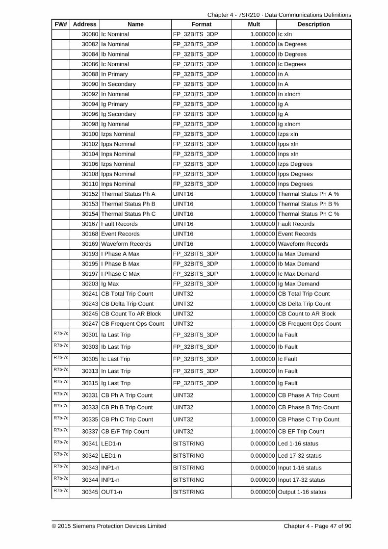
Chapter 4 - 7SR210 · Data Communications Definitions
© 2015 Siemens Protection Devices Limited Chapter 4 - Page 47 of 90
FW# Address Name Format Mult Description
30080 Ic Nominal FP_32BITS_3DP 1.000000 Ic xIn
30082 Ia Nominal FP_32BITS_3DP 1.000000 Ia Degrees
30084 Ib Nominal FP_32BITS_3DP 1.000000 Ib Degrees
30086 Ic Nominal FP_32BITS_3DP 1.000000 Ic Degrees
30088 In Primary FP_32BITS_3DP 1.000000 In A
30090 In Secondary FP_32BITS_3DP 1.000000 In A
30092 In Nominal FP_32BITS_3DP 1.000000 In xInom
30094 Ig Primary FP_32BITS_3DP 1.000000 Ig A
30096 Ig Secondary FP_32BITS_3DP 1.000000 Ig A
30098 Ig Nominal FP_32BITS_3DP 1.000000 Ig xInom
30100 Izps Nominal FP_32BITS_3DP 1.000000 Izps xIn
30102 Ipps Nominal FP_32BITS_3DP 1.000000 Ipps xIn
30104 Inps Nominal FP_32BITS_3DP 1.000000 Inps xIn
30106 Izps Nominal FP_32BITS_3DP 1.000000 Izps Degrees
30108 Ipps Nominal FP_32BITS_3DP 1.000000 Ipps Degrees
30110 Inps Nominal FP_32BITS_3DP 1.000000 Inps Degrees
30152 Thermal Status Ph A UINT16 1.000000 Thermal Status Ph A %
30153 Thermal Status Ph B UINT16 1.000000 Thermal Status Ph B %
30154 Thermal Status Ph C UINT16 1.000000 Thermal Status Ph C %
30167 Fault Records UINT16 1.000000 Fault Records
30168 Event Records UINT16 1.000000 Event Records
30169 Waveform Records UINT16 1.000000 Waveform Records
30193 I Phase A Max FP_32BITS_3DP 1.000000 Ia Max Demand
30195 I Phase B Max FP_32BITS_3DP 1.000000 Ib Max Demand
30197 I Phase C Max FP_32BITS_3DP 1.000000 Ic Max Demand
30203 Ig Max FP_32BITS_3DP 1.000000 Ig Max Demand
30241 CB Total Trip Count UINT32 1.000000 CB Total Trip Count
30243 CB Delta Trip Count UINT32 1.000000 CB Delta Trip Count
30245 CB Count To AR Block UINT32 1.000000 CB Count to AR Block
30247 CB Frequent Ops Count UINT32 1.000000 CB Frequent Ops Count
R7b-7c 30301 Ia Last Trip FP_32BITS_3DP 1.000000 Ia Fault
R7b-7c 30303 Ib Last Trip FP_32BITS_3DP 1.000000 Ib Fault
R7b-7c 30305 Ic Last Trip FP_32BITS_3DP 1.000000 Ic Fault
R7b-7c 30313 In Last Trip FP_32BITS_3DP 1.000000 In Fault
R7b-7c 30315 Ig Last Trip FP_32BITS_3DP 1.000000 Ig Fault
R7b-7c 30331 CB Ph A Trip Count UINT32 1.000000 CB Phase A Trip Count
R7b-7c 30333 CB Ph B Trip Count UINT32 1.000000 CB Phase B Trip Count
R7b-7c 30335 CB Ph C Trip Count UINT32 1.000000 CB Phase C Trip Count
R7b-7c 30337 CB E/F Trip Count UINT32 1.000000 CB EF Trip Count
R7b-7c 30341 LED1-n BITSTRING 0.000000 Led 1-16 status
R7b-7c 30342 LED1-n BITSTRING 0.000000 Led 17-32 status
R7b-7c 30343 INP1-n BITSTRING 0.000000 Input 1-16 status
R7b-7c 30344 INP1-n BITSTRING 0.000000 Input 17-32 status
R7b-7c 30345 OUT1-n BITSTRING 0.000000 Output 1-16 status

7SR210 Technical Manual
Chapter 4 - Page 48 of 90 © 2015 Siemens Protection Devices Limited
FW# Address Name Format Mult Description
R7b-7c 30346 OUT1-n BITSTRING 0.000000 Output 17-32 status
R7b-7c 30347 VRT1-n BITSTRING 0.000000 Virtual 1-16 status
R7b-7c 30348 VRT1-n BITSTRING 0.000000 Virtual 17-32 status
R7b-7c 30349 EQN1-n BITSTRING 0.000000 Equation 1-16 status
R7b-7c 30350 EQN1-n BITSTRING 0.000000 Equation 17-32 status
R7b-7c 30354 CB Wear A FP_32BITS_3DP 0.000001 CB Wear A
R7b-7c 30356 CB Wear B FP_32BITS_3DP 0.000001 CB Wear B
R7b-7c 30358 CB Wear C FP_32BITS_3DP 0.000001 CB Wear C
R7b-7c 30360 CB Wear A Remaining FP_32BITS_3DP 1.000000 CB Wear A Remaining
R7b-7c 30362 CB Wear B Remaining FP_32BITS_3DP 1.000000 CB Wear B Remaining
R7b-7c 30364 CB Wear C Remaining FP_32BITS_3DP 1.000000 CB Wear C Remaining
R7b-7c 30366 CB Wear Minimum FP_32BITS_3DP 1.000000 CB Wear Minimum
R7b-7c 30380 StartCount FP_32BITS_3DP 1.000000 Start Count
R7b-7c 30382 Start Count Target FP_32BITS_3DP 1.000000 Start Count Target
R7b-7c 30392 Active Setting Group UINT16 1.000000 Active Setting Group
R7e-7c 30400 Frequency Max FP_32BITS_3DP 1.000000 Frequency Max
R7f-7d 30468 CB Trip Time Meter FP_32BITS_3DP 1.000000 CB Trip Time
4.3.4 Holding Registers (Read Write Registers)
FW# Address Name Format Mult Description
40001 Time TIME_METER 0.000000 Time

Chapter 4 - 7SR210 · Data Communications Definitions
© 2015 Siemens Protection Devices Limited Chapter 4 - Page 49 of 90
5. DNP3 Definitions5.1 Device Profile
The following table provides a “Device Profile Document” in the standard format defined in the DNP 3.0 SubsetDefinitions Document. While it is referred to in the DNP 3.0 Subset Definitions as a “Document,” it is in fact a table, andonly a component of a total interoperability guide. The table, in combination with the Implementation Table providedin Section 5.2 (beginning on page 52), and the Point List Tables provided in Section 5.3 (beginning on page58), should provide a complete configuration/interoperability guide for communicating with a device implementingthe Triangle MicroWorks, Inc. DNP 3.0 Slave Source Code Library.
DNP V3.0DEVICE PROFILE DOCUMENT
(Also see the DNP 3.0 Implementation Table in Section 5.2, beginning on page 52).
Vendor Name: Siemens Protection Devices Ltd.
Device Name: 7SR210, using the Triangle MicroWorks, Inc. DNP3 Slave Source Code Library, Version 3.
Highest DNP Level Supported:For Requests: Level 3For Responses: Level 3
Device Function:Master
Slave
Notable objects, functions, and/or qualifiers supported in addition to the Highest DNP Levels Supported (thecomplete list is described in the attached table):
For static (non-change-event) object requests, request qualifier codes 07 and 08 (limited quantity), and 17 and 28(index) are supported. Static object requests sent with qualifiers 07, or 08, will be responded with qualifiers 00 or01.
Output Event Object 11 is supported.
Maximum Data Link Frame Size (octets):Transmitted: 256Received: 256
Maximum Application Fragment Size (octets):Transmitted: 2048Received: 2048
Maximum Data Link Re-tries:None
Fixed (3)
Configurable from 0 to 65535 (Default 3)
Maximum Application Layer Re-tries:NoneConfigurable
Requires Data Link Layer Confirmation:Never
Always
Sometimes
Configurable as: Never, Only for multi-frame messages, or Always
Requires Application Layer Confirmation:Never
Always
When reporting Event Data (Slave devices only)When sending multi-fragment responses (Slave devices only)Sometimes
Configurable as: “Only when reporting event data”, or “When reporting event data or multi-fragmentmessages.”
Timeouts while waiting for:
Data Link Confirm: None Fixed at ____ Variable Configurable (2sec)
Complete Appl. Fragment: None Fixed at ____ Variable Configurable
Application Confirm: None Fixed at ____ Variable Configurable (10sec)
Complete Appl. Response: None Fixed at ____ Variable Configurable
Others:
Transmission Delay, (Configurable, default 0 sec)
Select/Operate Arm Timeout, (Configurable, default 5 sec)
Need Time Interval, (Configurable, default 30 minutes)

7SR210 Technical Manual
Chapter 4 - Page 50 of 90 © 2015 Siemens Protection Devices Limited
DNP V3.0DEVICE PROFILE DOCUMENT
(Also see the DNP 3.0 Implementation Table in Section 5.2, beginning on page 52).
Unsolicited Notification Delay, (Configurable, default 5 seconds)
Unsolicited Response Retry Delay, (Configurable (between 3 - 9), default 5 seconds)
Unsolicited Offline Interval, (Configurable, default 30 seconds)
Binary Change Event Scan Period, (Polled, Not Applicable)
Double Bit Change Event Scan Period, (Polled - Not Applicable)
Analog Change Event Scan Period, (Polled - Not Applicable)
Counter Change Event Scan Period, (Polled - Not Applicable)
Frozen Counter Change Event Scan Period, (Polled - Not Applicable)
String Change Event Scan Period, (Unsupported - Not Applicable)
Virtual Terminal Event Scan Period, (Unsupported - Not Applicable)
Sends/Executes Control Operations:
WRITE Binary Outputs Never Always Sometimes Configurable
SELECT/OPERATE Never Always Sometimes Configurable
DIRECT OPERATE Never Always Sometimes Configurable
DIRECT OPERATE - NO ACK Never Always Sometimes Configurable
Count > 1 Never Always Sometimes Configurable
Pulse On Never Always Sometimes Configurable
Pulse Off Never Always Sometimes Configurable
Latch On Never Always Sometimes Configurable
Latch Off Never Always Sometimes Configurable
Queue Never Always Sometimes Configurable
Clear Queue Never Always Sometimes Configurable
Attach explanation if “Sometimes” or “Configurable” was checked for any operation.
Reports Binary Input Change Events when no specificvariation requested:
Never
Only time-tagged
Only non-time-tagged
Configurable to send one or the other
Reports time-tagged Binary Input Change Events whenno specific variation requested:
Never
Binary Input Change With Time
Binary Input Change With Relative Time
Configurable
Sends Unsolicited Responses:Never
ConfigurableOnly certain objects
Sometimes (attach explanation)
ENABLE/DISABLE UNSOLICITEDFunction codes supported
Sends Static Data in Unsolicited Responses:NeverWhen Device Restarts
When Status Flags Change
No other options are permitted.
Default Counter Object/Variation:No Counters Reported
ConfigurableDefault Object
Default Variation: _____Point-by-point list attached
Counters Roll Over at:No Counters Reported
Configurable (attach explanation)
16 Bits
32 BitsOther Value: _____
Point-by-point list attached
Sends Multi-Fragment Responses:YesNo
Configurable
Sequential File Transfer Support:

Chapter 4 - 7SR210 · Data Communications Definitions
© 2015 Siemens Protection Devices Limited Chapter 4 - Page 51 of 90
DNP V3.0DEVICE PROFILE DOCUMENT
(Also see the DNP 3.0 Implementation Table in Section 5.2, beginning on page 52).
File Transfer Support Yes No
Append File Mode Yes No
Custom Status Code Strings Yes No
Permissions Field Yes No
File Events Assigned to Class Yes No
File Events Send Immediately Yes No
Multiple Blocks in a Fragment Yes No
Max Number of Files Open 0

7SR210 Technical Manual
Chapter 4 - Page 52 of 90 © 2015 Siemens Protection Devices Limited
5.2 Implementation Table
The following table identifies which object variations, function codes, and qualifiers the Triangle MicroWorks, Inc.DNP 3.0 Slave Source Code Library supports in both request messages and in response messages. For static (non-change-event) objects, requests sent with qualifiers 00, 01, 06, 07, or 08, will be responded with qualifiers 00 or 01.Requests sent with qualifiers 17 or 28 will be responded with qualifiers 17 or 28. For change-event objects, qualifiers17 or 28 are always responded.
In the table below, text shaded as 00, 01 (start stop) indicates Subset Level 3 functionality (beyond Subset Level 2).
In the table below, text shaded as 07, 08 (limited qty) indicates functionality beyond Subset Level 3.
OBJECTREQUEST
(Library will parse)RESPONSE
(Library will respond with)
ObjectNumber
Variation DescriptionFunction Codes
(dec)Qualifier Codes
(hex)
FunctionCodes(dec)
Qualifier Codes(hex)
1 0Binary Input
- Any Variation1 (read)
22 (assign class)
00, 01 (start-stop)06 (no range, or all)07, 08 (limited qty)17, 27, 28 (index)
1 1 Binary Input 1 (read)
00, 01 (start-stop)06 (no range, or all)07, 08 (limited qty)17, 27, 28 (index)
129(response)
00, 01 (start-stop)17, 28 (index- see note 2)
12 (default -see note 1)
Binary Inputwith Status
1 (read)
00, 01 (start-stop)06 (no range, or all)07, 08 (limited qty)17, 27, 28 (index)
129(response)
00, 01 (start-stop)17, 28 (index- see note 2)
2 0Binary Input Change
- Any Variation1 (read)
06 (no range, or all)07, 08 (limited qty)
2 1Binary Input Change
without Time1 (read)
06 (no range, or all)07, 08 (limited qty)
129(response)
130(unsol. resp)
17, 28 (index)
22 (default -see note 1)
Binary Input Changewith Time
1 (read)06 (no range, or all)07, 08 (limited qty)
129(response)
130(unsol. resp)
17, 28 (index)
2 3Binary Input Changewith Relative Time
1 (read)06 (no range, or all)07, 08 (limited qty)
129(response)
130(unsol. resp)
17, 28 (index)
3 0Double Bit Input- Any Variation
1 (read)22 (assign class)
00, 01 (start-stop)06 (no range, or all)07, 08 (limited qty)17, 27, 28 (index)
31 (default -see note 1)
Double Bit Input 1 (read)
00, 01 (start-stop)06 (no range, or all)07, 08 (limited qty)17, 27, 28 (index)
129(response)
00, 01 (start-stop)17, 28 (index- see note 1)
3 2Double Bit Input
with Status1 (read)
00, 01 (start-stop)06 (no range, or all)07, 08 (limited qty)17, 27, 28 (index)
129(response)
00, 01 (start-stop)17, 28 (index- see note 1)
4 0Double Bit Input Change
- Any Variation1 (read)
06 (no range, or all)07, 08 (limited qty)
4 1Double Bit Input Change
without Time1 (read)
06 (no range, or all)07, 08 (limited qty)
129(response)
130(unsol. resp)
17, 28 (index)
4 2Double Bit Input Change
with Time1 (read)
06 (no range, or all)07, 08 (limited qty)
129(response)
130(unsol. resp)
17, 28 (index)
43 (default -see note 1)
Double Bit Input Changewith Relative Time
1 (read)06 (no range, or all)07, 08 (limited qty)
129(response)
130(unsol. resp)
17, 28 (index)
10 0Binary Output- Any Variation
1 (read)22 (assign class)
00, 01 (start-stop)06 (no range, or all)07, 08 (limited qty)17, 27, 28 (index)

Chapter 4 - 7SR210 · Data Communications Definitions
© 2015 Siemens Protection Devices Limited Chapter 4 - Page 53 of 90
OBJECTREQUEST
(Library will parse)RESPONSE
(Library will respond with)
ObjectNumber
Variation DescriptionFunction Codes
(dec)Qualifier Codes
(hex)
FunctionCodes(dec)
Qualifier Codes(hex)
1 (read)
00, 01 (start-stop)06 (no range, or all)07, 08 (limited qty)17, 27, 28 (index)
129(response)
00, 01 (start-stop)17, 28 (index- see note 2)10 1 Binary Output
2 (write) 00, 01 (start-stop)
102 (default -see note 1)
Binary OutputStatus
1 (read)
00, 01 (start-stop)06 (no range, or all)07, 08 (limited qty)17, 27, 28 (index)
129(response)
00, 01 (start-stop)17, 28 (index- see note 2)
11 0Binary Output Change
- Any Variation1 (read)
06 (no range, or all)07, 08 (limited qty)
11 1Binary Output Change
without Time1 (read)
06 (no range, or all)07, 08 (limited qty)
129(response)
130(unsol. resp)
17, 28 (index)
112 (default -see note 1)
Binary Output Changewith Time
1 (read)06 (no range, or all)07, 08 (limited qty)
129(response)
130(unsol. resp)
17, 28 (index)
12 0Control RelayOutput Block
22 (assign class)
00, 01 (start-stop)06 (no range, or all)07, 08 (limited qty)17, 27, 28 (index)
12 1Control RelayOutput Block
3 (select)4 (operate)5 (direct op)
6 (dir. op, noack)
17, 28 (index)129
(response)echo of request
12 2Pattern Control
Block
3 (select)4 (operate)5 (direct op)
6 (dir. op, noack)
7 (limited quantity)129
(response)echo of request
12 3 Pattern Mask
3 (select)4 (operate)5 (direct op)
6 (dir. op, noack)
00, 01 (start-stop)129
(response)echo of request
13 0Binary Output
Command Event- Any Variation
1 (read)06 (no range, or all)07, 08 (limited qty)
131 (default -see note 1)
Binary OutputCommand Event
without Time1 (read)
06 (no range, or all)07, 08 (limited qty)
129(response)
130(unsol. resp)
17, 28 (index)
13 2Binary Output
Command Eventwith Time
1 (read)06 (no range, or all)07, 08 (limited qty)
129(response)
130(unsol. resp)
17, 28 (index)
1 (read)22 (assign class)
00, 01 (start-stop)06 (no range, or all)07, 08 (limited qty)17, 27, 28 (index)
20 0Binary Counter- Any Variation 7 (freeze)
8 (freeze noack)9 (freeze clear)
10 (frz. cl. noack)
00, 01 (start-stop)06 (no range, or all)07, 08 (limited qty)
20 132-Bit Binary Counter
(with Flag)1 (read)
00, 01 (start-stop)06 (no range, or all)07, 08 (limited qty)17, 27, 28 (index)
129(response)
00, 01 (start-stop)17, 28 (index- see note 2)
20 216-Bit Binary Counter
(with Flag)1 (read)
00, 01 (start-stop)06 (no range, or all)07, 08 (limited qty)17, 27, 28 (index)
129(response)
00, 01 (start-stop)17, 28 (index- see note 2)
20 332-Bit Delta Counter
(with Flag)
20 416-Bit Delta Counter
(with Flag)
205 (default
see note 1)32-Bit Binary Counter
(without Flag)1 (read)
00, 01 (start-stop)06 (no range, or all)07, 08 (limited qty)17, 27, 28 (index)
129(response)
00, 01 (start-stop)17, 28 (index- see note 2)

7SR210 Technical Manual
Chapter 4 - Page 54 of 90 © 2015 Siemens Protection Devices Limited
OBJECTREQUEST
(Library will parse)RESPONSE
(Library will respond with)
ObjectNumber
Variation DescriptionFunction Codes
(dec)Qualifier Codes
(hex)
FunctionCodes(dec)
Qualifier Codes(hex)
20 616-Bit Binary Counter
(without Flag)1 (read)
00, 01 (start-stop)06 (no range, or all)07, 08 (limited qty)17, 27, 28 (index)
129(response)
00, 01 (start-stop)17, 28 (index- see note 2)
20 732-Bit Delta Counter
(without Flag)
20 816-Bit Delta Counter
(without Flag)
21 0Frozen Counter- Any Variation
1 (read)22 (assign class)
00, 01 (start-stop)06 (no range, or all)07, 08 (limited qty)17, 27, 28 (index)
21 132-Bit Frozen Counter
(with Flag)1 (read)
00, 01 (start-stop)06 (no range, or all)07, 08 (limited qty)17, 27, 28 (index)
129(response)
00, 01 (start-stop)17, 28 (index- see note 2)
21 216-Bit Frozen Counter
(with Flag)1 (read)
00, 01 (start-stop)06 (no range, or all)07, 08 (limited qty)17, 27, 28 (index)
129(response)
00, 01 (start-stop)17, 28 (index- see note 2)
21 332-Bit Frozen DeltaCounter (with Flag)
21 416-Bit Frozen DeltaCounter (with Flag)
21 532-Bit Frozen Counter
(without Time Of Freeze)1 (read)
00, 01 (start-stop)06 (no range, or all)07, 08 (limited qty)17, 27, 28 (index)
129(response)
00, 01 (start-stop)17, 28 (index- see note 2)
21 616-Bit Frozen Counter
(without Time Of Freeze)1 (read)
00, 01 (start-stop)06 (no range, or all)07, 08 (limited qty)17, 27, 28 (index)
129(response)
00, 01 (start-stop)17, 28 (index- see note 2)
21 732-Bit Frozen Delta Counter
(with Time Of Freeze)
21 816-Bit Frozen Delta Counter
(with Time Of Freeze)
219 (default -see note 1)
32-Bit Frozen Counter(without Flag)
1 (read)
00, 01 (start-stop)06 (no range, or all)07, 08 (limited qty)17, 27, 28 (index)
129(response)
00, 01 (start-stop)17, 28 (index- see note 2)
21 1016-Bit Frozen Counter
(without Flag)1 (read)
00, 01 (start-stop)06 (no range, or all)07, 08 (limited qty)17, 27, 28 (index)
129(response)
00, 01 (start-stop)17, 28 (index- see note 2)
21 1132-Bit Frozen Delta Counter
(without Flag)
21 1216-Bit Frozen Delta Counter
(without Flag)
22 0Counter Change Event
- Any Variation1 (read)
06 (no range, or all)07, 08 (limited qty)
221 (default -see note 1)
32-Bit Counter ChangeEvent (without Time)
1 (read)06 (no range, or all)07, 08 (limited qty)
129(response)
130(unsol. resp)
17, 28 (index)
22 216-Bit Counter ChangeEvent (without Time)
1 (read)06 (no range, or all)07, 08 (limited qty)
129(response)
130(unsol. resp)
17, 28 (index)
22 332-Bit Delta Counter
Change Event(without Time)
22 416-Bit Delta Counter
Change Event(without Time)
22 532-Bit Counter Change
Event (with Time)1 (read)
06 (no range, or all)07, 08 (limited qty)
129(response)
130(unsol. resp)
17, 28 (index)
22 616-Bit Counter Change
Event (with Time)1 (read)
06 (no range, or all)07, 08 (limited qty)
129(response)
13017, 28 (index)

Chapter 4 - 7SR210 · Data Communications Definitions
© 2015 Siemens Protection Devices Limited Chapter 4 - Page 55 of 90
OBJECTREQUEST
(Library will parse)RESPONSE
(Library will respond with)
ObjectNumber
Variation DescriptionFunction Codes
(dec)Qualifier Codes
(hex)
FunctionCodes(dec)
Qualifier Codes(hex)
(unsol. resp)
22 732-Bit Delta Counter
Change Event (with Time)
22 816-Bit Delta Counter
Change Event (with Time)
23 0Frozen Counter Event(Variation 0 is used to
request default variation)1 (read)
06 (no range, or all)07, 08 (limited qty)
231 (default -see note 1)
32-Bit FrozenCounter Event
1 (read)06 (no range, or all)07, 08 (limited qty)
129(response)
17, 28 (index)
23 216-Bit FrozenCounter Event
1 (read)06 (no range, or all)07, 08 (limited qty)
129(response)
17, 28 (index)
23 332-Bit Frozen Delta
Counter Event
23 416-Bit Frozen Delta
Counter Event
23 532-Bit Frozen Counter
Event (with Time)1 (read)
06 (no range, or all)07, 08 (limited qty)
129(response)
130(unsol. resp)
17, 28 (index)
23 632-Bit Frozen Counter
Event (with Time)1 (read)
06 (no range, or all)07, 08 (limited qty)
129(response)
130(unsol. resp)
17, 28 (index)
23 732-Bit Frozen Delta Counter
Event (with Time)
23 816-Bit Frozen Delta Counter
Event (with Time)
30 0Analog Input
- Any Variation1 (read)
22 (assign class)
00, 01 (start-stop)06 (no range, or all)07, 08 (limited qty)17, 27, 28 (index)
30 1 32-Bit Analog Input 1 (read)
00, 01 (start-stop)06 (no range, or all)07, 08 (limited qty)17, 27, 28 (index)
129(response)
00, 01 (start-stop)17, 28 (index- see note 2)
302 (default -see note 1)
16-Bit Analog Input 1 (read)
00, 01 (start-stop)06 (no range, or all)07, 08 (limited qty)17, 27, 28 (index)
129(response)
00, 01 (start-stop)17, 28 (index- see note 2)
30 332-Bit Analog Input
(without Flag)1 (read)
00, 01 (start-stop)06 (no range, or all)07, 08 (limited qty)17, 27, 28 (index)
129(response)
00, 01 (start-stop)17, 28 (index- see note 2)
30 416-Bit Analog Input
(without Flag)1 (read)
00, 01 (start-stop)06 (no range, or all)07, 08 (limited qty)17, 27, 28 (index)
129(response)
00, 01 (start-stop)17, 28 (index- see note 2)
30 5 short floating point 1 (read)
00, 01 (start-stop)06 (no range, or all)07, 08 (limited qty)17, 27, 28 (index)
129(response)
00, 01 (start-stop)17, 28 (index- see note 2)
30 6 long floating point 1 (read)
00, 01 (start-stop)06 (no range, or all)07, 08 (limited qty)17, 27, 28 (index)
129(response)
00, 01 (start-stop)17, 28 (index- see note 2)
31 0Frozen Analog Input
- Any Variation
31 1 32-Bit Frozen Analog Input
31 2 16-Bit Frozen Analog Input
31 332-Bit Frozen Analog Input
(with Time of freeze)
31 416-Bit Frozen Analog Input
(with Time of freeze)
31 532-Bit Frozen Analog Input
(without Flag)
31 616-Bit Frozen Analog Input
(without Flag)

7SR210 Technical Manual
Chapter 4 - Page 56 of 90 © 2015 Siemens Protection Devices Limited
OBJECTREQUEST
(Library will parse)RESPONSE
(Library will respond with)
ObjectNumber
Variation DescriptionFunction Codes
(dec)Qualifier Codes
(hex)
FunctionCodes(dec)
Qualifier Codes(hex)
32 0Analog Change Event
- Any Variation)1 (read)
06 (no range, or all)07, 08 (limited qty)
32 132Bit-Analog Change Event
(without Time)1 (read)
06 (no range, or all)07, 08 (limited qty)
129(response)
130(unsol. resp)
17, 28 (index)
32 216Bit-Analog Change Event
(without Time)1 (read)
06 (no range, or all)07, 08 (limited qty)
129(response)
130(unsol. resp)
17, 28 (index)
32 332Bit-Analog Change Event
(with Time)1 (read)
06 (no range, or all)07, 08 (limited qty)
129(response)
130(unsol. resp)
17, 28 (index)
324 (default -see note 1)
16Bit-Analog Change Event(with Time)
1 (read)06 (no range, or all)07, 08 (limited qty)
129(response)
130(unsol. resp)
17, 28 (index)
32 5short floating point
Analog Change Event(without Time)
1 (read)06 (no range, or all)07, 08 (limited qty)
129(response)
130(unsol. resp)
17, 28 (index)
32 6long floating point
Analog Change Event(without Time)
1 (read)06 (no range, or all)07, 08 (limited qty)
129(response)
130(unsol. resp)
17, 28 (index)
32 7short floating point
Analog Change Event(with Time)
1 (read)06 (no range, or all)07, 08 (limited qty)
129(response)
130(unsol. resp)
17, 28 (index)
32 8long floating point
Analog Change Event(with Time)
1 (read)06 (no range, or all)07, 08 (limited qty)
129(response)
130(unsol. resp)
17, 28 (index)
33 0Frozen Analog Event
- Any Variation
33 132-Bit Frozen Analog Event
(without Time)
33 216-Bit Frozen Analog Event
(without Time)
33 332-Bit Frozen Analog Event
(with Time)
33 416-Bit Frozen Analog Event
(with Time)
33 5Short Floating PointFrozen Analog Event
33 6Long Floating Point
Frozen Analog Event
33 7Extended Floating Point
Frozen Analog Event
34 0Analog Input Deadband(Variation 0 is used to
request default variation)1 (read)
00, 01 (start-stop)06 (no range, or all)07, 08 (limited qty)17, 27, 28 (index)
1 (read)
00, 01 (start-stop)06 (no range, or all)07, 08 (limited qty)17, 27, 28 (index)
129(response)
00, 01 (start-stop)17, 28 (index- see note 2)
34 116 bit Analog
Input Deadband
2 (write)00, 01 (start-stop)07, 08 (limited qty)17, 27, 28 (index)
1 (read)
00, 01 (start-stop)06 (no range, or all)07, 08 (limited qty)17, 27, 28 (index)
129(response)
00, 01 (start-stop)17, 28 (index- see note 2)
342 (default -see note 1)
32 bit AnalogInput Deadband
2 (write)00, 01 (start-stop)07, 08 (limited qty)17, 27, 28 (index)
34 3Short Floating Point
Analog Input Deadband1 (read)
00, 01 (start-stop)06 (no range, or all)07, 08 (limited qty)
129(response)
00, 01 (start-stop)17, 28 (index- see note 2)

Chapter 4 - 7SR210 · Data Communications Definitions
© 2015 Siemens Protection Devices Limited Chapter 4 - Page 57 of 90
OBJECTREQUEST
(Library will parse)RESPONSE
(Library will respond with)
ObjectNumber
Variation DescriptionFunction Codes
(dec)Qualifier Codes
(hex)
FunctionCodes(dec)
Qualifier Codes(hex)
17, 27, 28 (index)
2 (write)00, 01 (start-stop)07, 08 (limited qty)17, 27, 28 (index)
50 0 Time and Date
1 (read) 07, 08 (limited qty)129
(response)07 (limited qty = 1)
501 (default -see note 1)
Time and Date
2 (write)00, 01 (start-stop)07, 08 (limited qty)17, 27, 28 (index)
50 3Time and Date Last
Recorded Time2 (write) 07 (limited qty)
51 1 Time and Date CTO
129(response)
130(unsol. resp)
(limited qty = 1)
51 2Unsynchronized
Time and Date CTO
129(response)
130(unsol. resp)
(limited qty = 1)
52 1 Time Delay Coarse129
(response)(limited qty = 1)
52 2 Time Delay Fine129
(response)(limited qty = 1)
60 0 Not Defined
60 1 Class 0 Data 1 (read) 06 (no range, or all)
1 (read)06 (no range, or all)07, 08 (limited qty)
60 2 Class 1 Data 20 (enbl. unsol.)21 (dab. unsol.)22 (assign class)
06 (no range, or all)
1 (read)06 (no range, or all)07, 08 (limited qty)
60 3 Class 2 Data 20 (enbl. unsol.)21 (dab. unsol.)22 (assign class)
06 (no range, or all)
1 (read)06 (no range, or all)07, 08 (limited qty)
60 4 Class 3 Data 20 (enbl. unsol.)21 (dab. unsol.)22 (assign class)
06 (no range, or all)
1 (read) 00, 01 (start-stop)129
(response)00, 01 (start-stop)
80 1 Internal Indications
2 (write)(see note 3)00 (start-
stop) index=7
No Object(function code only)
13 (cold restart)
No Object(function code only)
14 (warm restart)
No Object(function code only)
23 (delay meas.)
No Object(function code only)
24 (recordcurrent time)
Note 1: A Default variation refers to the variation responded when variation 0 is requested and/or in class 0, 1, 2, or3 scans. Default variations are configurable; however, default settings for the configuration parameters are indicatedin the table above.
Note 2: For static (non-change-event) objects, qualifiers 17 or 28 are only responded when a request is sent withqualifiers 17 or 28, respectively. Otherwise, static object requests sent with qualifiers 00, 01, 06, 07, or 08, will beresponded with qualifiers 00 or 01. (For change-event objects, qualifiers 17 or 28 are always responded.)
Note 3: Writes of Internal Indications are only supported for index 7 (Restart IIN1-7).

7SR210 Technical Manual
Chapter 4 - Page 58 of 90 © 2015 Siemens Protection Devices Limited
5.3 Point List
The tables below identify all the default data points provided by the implementation of the Triangle MicroWorks, Inc.DNP 3.0 Slave Source Code Library.
This protocol can be set to use any or all of the relays hardware interfaces (USB, Fibre Optic, RS232 and RS485).The relay can communicate simultaneously on all ports regardless of protocol used.
The Station Address of the port being used must be set to a suitable address within the range 0 - 65534 to enablecommunication. This can be set by the Communications Menu : COM n-xxxxx Station Address setting.
Communication via DNP3 over Ethernet requires external devices. Please refer to the documents TCPIP CatalogueSheet and TCPIP Interface Technical Guidance Notes for more information.
The information shown below is the default configuration. This can be modified using the CommunicationsConfiguration Editor tool, refer section 9 for details.
5.3.1 Binary Input Points
The default binary input event buffer size is set to allow 100 events.
Binary inputs are by default returned in a class zero interrogation.
Note, not all points listed here apply to all builds of devices.
Binary Input PointsStatic (Steady-State) Object Number: 1 (Packed Format)Change Event Object Number: 1 (w/o Time)Static Variation reported when variation 0 requested: 1 (Binary Input w/o status)
or 2 (Binary Input with status)Change Event Variation reported when variation 0 requested: 1 (Binary Input Change w/o Time)
or 2 (Binary Input Change with Absolute Time)or 3 (Binary Input Change with Relative Time)
FW#PointIndex
Name(Description)
Default Change EventAssigned Class(1, 2, 3 or none)
Default VariationStatic Object 1
Default VariationEvent Object 2
1 Binary Input 1 0,2 2 2
2 Binary Input 2 0,2 2 2
3 Binary Input 3 0,2 2 2
4 Binary Input 4 0,2 2 2
5 Binary Input 5 0,2 2 2
6 Binary Input 6 0,2 2 2
7 Binary Input 7 0,2 2 2
8 Binary Input 8 0,2 2 2
9 Binary Input 9 0,2 2 2
10 Binary Input 10 0,2 2 2
11 Binary Input 11 0,2 2 2
12 Binary Input 12 0,2 2 2
13 Binary Input 13 0,2 2 2
14 Binary Input 14 0,2 2 2
15 Binary Input 15 0,2 2 2
16 Binary Input 16 0,2 2 2
17 Binary Input 17 0,2 2 2
18 Binary Input 18 0,2 2 2
19 Binary Input 19 0,2 2 2
35 Remote Mode 0,2 2 2

Chapter 4 - 7SR210 · Data Communications Definitions
© 2015 Siemens Protection Devices Limited Chapter 4 - Page 59 of 90
Binary Input PointsStatic (Steady-State) Object Number: 1 (Packed Format)Change Event Object Number: 1 (w/o Time)Static Variation reported when variation 0 requested: 1 (Binary Input w/o status)
or 2 (Binary Input with status)Change Event Variation reported when variation 0 requested: 1 (Binary Input Change w/o Time)
or 2 (Binary Input Change with Absolute Time)or 3 (Binary Input Change with Relative Time)
FW#PointIndex
Name(Description)
Default Change EventAssigned Class(1, 2, 3 or none)
Default VariationStatic Object 1
Default VariationEvent Object 2
36 Out Of Service Mode 0,2 2 2
37 Local Mode 0,2 2 2
38 Local & Remote 0,2 2 2
R7b-7c 40 General Trip 0,2 2 2
41 Trip Circuit Fail 0,2 2 2
42 Start/Pick-up L1 0,2 2 2
43 Start/Pick-up L2 0,2 2 2
44 Start/Pick-up L3 0,2 2 2
45 General Start/Pick-up 0,2 2 2
49 Start/Pick-up N 0,2 2 2
52 51-1 0,2 2 2
53 50-1 0,2 2 2
54 51N-1 0,2 2 2
55 50N-1 0,2 2 2
56 51G-1 0,2 2 2
57 50G-1 0,2 2 2
58 51-2 0,2 2 2
59 50-2 0,2 2 2
60 51N-2 0,2 2 2
61 50N-2 0,2 2 2
62 51G-2 0,2 2 2
63 50G-2 0,2 2 2
65 46IT 0,2 2 2
66 46DT 0,2 2 2
69 46BC 0,2 2 2
80 Auto-reclose active 0,2 2 2
81 CB on by auto reclose 0,2 2 2
82 Reclaim 0,2 2 2
83 Lockout 0,2 2 2
98 Cold Load Active 0,2 2 2
99 E/F Out 0,2 2 2
100 P/F Inst Protection Inhibited 0,2 2 2
101 E/F Inst Protection Inhibited 0,2 2 2
102 SEF Inst Protection Inhibited 0,2 2 2
103 Ext Inst Protection Inhibited 0,2 2 2
117 51SEF-1 0,2 2 2
118 50SEF-1 0,2 2 2
119 51SEF-2 0,2 2 2
120 50SEF-2 0,2 2 2
125 SEF Out 0,2 2 2

7SR210 Technical Manual
Chapter 4 - Page 60 of 90 © 2015 Siemens Protection Devices Limited
Binary Input PointsStatic (Steady-State) Object Number: 1 (Packed Format)Change Event Object Number: 1 (w/o Time)Static Variation reported when variation 0 requested: 1 (Binary Input w/o status)
or 2 (Binary Input with status)Change Event Variation reported when variation 0 requested: 1 (Binary Input Change w/o Time)
or 2 (Binary Input Change with Absolute Time)or 3 (Binary Input Change with Relative Time)
FW#PointIndex
Name(Description)
Default Change EventAssigned Class(1, 2, 3 or none)
Default VariationStatic Object 1
Default VariationEvent Object 2
126 Trip Circuit Fail 1 0,2 2 2
127 Trip Circuit Fail 2 0,2 2 2
128 Trip Circuit Fail 3 0,2 2 2
129 CB Total Trip Count 0,2 2 2
130 CB Delta Trip Count 0,2 2 2
131 CB Count To AR Block 0,2 2 2
132 CB Frequent Ops Count 0,2 2 2
133 I^2t CB Wear 0,2 2 2
207 Close Circuit Fail 1 0,2 2 2
208 Close Circuit Fail 2 0,2 2 2
209 Close Circuit Fail 3 0,2 2 2
210 Close Circuit Fail 0,2 2 2
211 50BF Stage 1 0,2 2 2
212 50BF Stage 2 0,2 2 2
213 49-Alarm 0,2 2 2
214 49-Trip 0,2 2 2
215 64H 0,2 2 2
217 37-1 0,2 2 2
218 37-2 0,2 2 2
219 CB Alarm 0,2 2 2
225 General Alarm 1 0,2 2 2
226 General Alarm 2 0,2 2 2
227 General Alarm 3 0,2 2 2
228 General Alarm 4 0,2 2 2
229 General Alarm 5 0,2 2 2
230 General Alarm 6 0,2 2 2
231 General Alarm 7 0,2 2 2
232 General Alarm 8 0,2 2 2
233 General Alarm 9 0,2 2 2
234 General Alarm 10 0,2 2 2
235 General Alarm 11 0,2 2 2
236 General Alarm 12 0,2 2 2
237 Quick Logic E1 0,2 2 2
238 Quick Logic E2 0,2 2 2
239 Quick Logic E3 0,2 2 2
240 Quick Logic E4 0,2 2 2
241 Quick Logic E5 0,2 2 2
242 Quick Logic E6 0,2 2 2
243 Quick Logic E7 0,2 2 2
244 Quick Logic E8 0,2 2 2
245 Quick Logic E9 0,2 2 2
246 Quick Logic E10 0,2 2 2

Chapter 4 - 7SR210 · Data Communications Definitions
© 2015 Siemens Protection Devices Limited Chapter 4 - Page 61 of 90
Binary Input PointsStatic (Steady-State) Object Number: 1 (Packed Format)Change Event Object Number: 1 (w/o Time)Static Variation reported when variation 0 requested: 1 (Binary Input w/o status)
or 2 (Binary Input with status)Change Event Variation reported when variation 0 requested: 1 (Binary Input Change w/o Time)
or 2 (Binary Input Change with Absolute Time)or 3 (Binary Input Change with Relative Time)
FW#PointIndex
Name(Description)
Default Change EventAssigned Class(1, 2, 3 or none)
Default VariationStatic Object 1
Default VariationEvent Object 2
247 Quick Logic E11 0,2 2 2
248 Quick Logic E12 0,2 2 2
249 Quick Logic E13 0,2 2 2
250 Quick Logic E14 0,2 2 2
251 Quick Logic E15 0,2 2 2
252 Quick Logic E16 0,2 2 2
269 60 CTS-I 0,2 2 2
270 81HBL2 0,2 2 2
271 37G-1 0,2 2 2
272 37G-2 0,2 2 2
R7b-7c 274 37-PhA 0,2 2 2
R7b-7c 275 37-PhB 0,2 2 2
R7b-7c 276 37-PhC 0,2 2 2
R7b-7c 283 50BF-PhA 0,2 2 2
R7b-7c 284 50BF-PhB 0,2 2 2
R7b-7c 285 50BF-PhC 0,2 2 2
R7b-7c 286 50BF-EF 0,2 2 2
R7b-7c 287 79 Last Trip Lockout 0,2 2 2
R7b-7c 288 60 CTS-I-PhA 0,2 2 2
R7b-7c 289 60 CTS-I-PhB 0,2 2 2
R7b-7c 290 60 CTS-I-PhC 0,2 2 2
R7b-7c 291 Trip PhA 0,2 2 2
R7b-7c 292 Trip PhB 0,2 2 2
R7b-7c 293 Trip PhC 0,2 2 2
R7b-7c 310 General Alarm 13 0,2 2 2
R7b-7c 311 General Alarm 14 0,2 2 2
R7b-7c 312 General Alarm 15 0,2 2 2
R7b-7c 313 General Alarm 16 0,2 2 2
R7b-7c 314 General Alarm 17 0,2 2 2
R7b-7c 315 General Alarm 18 0,2 2 2
R7b-7c 316 General Alarm 19 0,2 2 2
R7b-7c 317 General Alarm 20 0,2 2 2
R7b-7c 411 Setting G1 selected 0,2 2 2
R7b-7c 412 Setting G2 selected 0,2 2 2
R7b-7c 413 Setting G3 selected 0,2 2 2

7SR210 Technical Manual
Chapter 4 - Page 62 of 90 © 2015 Siemens Protection Devices Limited
Binary Input PointsStatic (Steady-State) Object Number: 1 (Packed Format)Change Event Object Number: 1 (w/o Time)Static Variation reported when variation 0 requested: 1 (Binary Input w/o status)
or 2 (Binary Input with status)Change Event Variation reported when variation 0 requested: 1 (Binary Input Change w/o Time)
or 2 (Binary Input Change with Absolute Time)or 3 (Binary Input Change with Relative Time)
FW#PointIndex
Name(Description)
Default Change EventAssigned Class(1, 2, 3 or none)
Default VariationStatic Object 1
Default VariationEvent Object 2
R7b-7c 414 Setting G4 selected 0,2 2 2
R7b-7c 415 Setting G5 selected 0,2 2 2
R7b-7c 416 Setting G6 selected 0,2 2 2
R7b-7c 417 Setting G7 selected 0,2 2 2
R7b-7c 418 Setting G8 selected 0,2 2 2
R7b-7c 420 79 AR In progress 0,2 2 2
R7b-7c 422 HotLine Working 0,2 2 2
R7b-7c 425 Inst Protection Out 0,2 2 2
R7b-7c 427 CB 1 0,2 2 2
R7b-7c 501 Virtual Input 1 0,2 2 2
R7b-7c 502 Virtual Input 2 0,2 2 2
R7b-7c 503 Virtual Input 3 0,2 2 2
R7b-7c 504 Virtual Input 4 0,2 2 2
R7b-7c 505 Virtual Input 5 0,2 2 2
R7b-7c 506 Virtual Input 6 0,2 2 2
R7b-7c 507 Virtual Input 7 0,2 2 2
R7b-7c 508 Virtual Input 8 0,2 2 2
R7b-7c 509 Virtual Input 9 0,2 2 2
R7b-7c 510 Virtual Input 10 0,2 2 2
R7b-7c 511 Virtual Input 11 0,2 2 2
R7b-7c 512 Virtual Input 12 0,2 2 2
R7b-7c 513 Virtual Input 13 0,2 2 2
R7b-7c 514 Virtual Input 14 0,2 2 2
R7b-7c 515 Virtual Input 15 0,2 2 2
R7b-7c 516 Virtual Input 16 0,2 2 2
R7b-7c 601 LED 1 0,2 2 2
R7b-7c 602 LED 2 0,2 2 2
R7b-7c 603 LED 3 0,2 2 2
R7b-7c 604 LED 4 0,2 2 2
R7b-7c 605 LED 5 0,2 2 2
R7b-7c 606 LED 6 0,2 2 2
R7b-7c 607 LED 7 0,2 2 2
R7b-7c 608 LED 8 0,2 2 2
R7b-7c 609 LED 9 0,2 2 2

Chapter 4 - 7SR210 · Data Communications Definitions
© 2015 Siemens Protection Devices Limited Chapter 4 - Page 63 of 90
Binary Input PointsStatic (Steady-State) Object Number: 1 (Packed Format)Change Event Object Number: 1 (w/o Time)Static Variation reported when variation 0 requested: 1 (Binary Input w/o status)
or 2 (Binary Input with status)Change Event Variation reported when variation 0 requested: 1 (Binary Input Change w/o Time)
or 2 (Binary Input Change with Absolute Time)or 3 (Binary Input Change with Relative Time)
FW#PointIndex
Name(Description)
Default Change EventAssigned Class(1, 2, 3 or none)
Default VariationStatic Object 1
Default VariationEvent Object 2
R7b-7c 610 LED 10 0,2 2 2
R7b-7c 611 LED 11 0,2 2 2
R7b-7c 612 LED 12 0,2 2 2
R7b-7c 613 LED 13 0,2 2 2
R7b-7c 614 LED 14 0,2 2 2
R7b-7c 615 LED 15 0,2 2 2
R7b-7c 616 LED 16 0,2 2 2
R7b-7c 701 LED PU 1 0,2 2 2
R7b-7c 702 LED PU 2 0,2 2 2
R7b-7c 703 LED PU 3 0,2 2 2
R7b-7c 704 LED PU 4 0,2 2 2
R7b-7c 705 LED PU 5 0,2 2 2
R7b-7c 706 LED PU 6 0,2 2 2
R7b-7c 707 LED PU 7 0,2 2 2
R7b-7c 708 LED PU 8 0,2 2 2
R7b-7c 709 LED PU 9 0,2 2 2
R7b-7c 710 LED PU 10 0,2 2 2
R7b-7c 711 LED PU 11 0,2 2 2
R7b-7c 712 LED PU 12 0,2 2 2
R7b-7c 713 LED PU 13 0,2 2 2
R7b-7c 714 LED PU 14 0,2 2 2
R7b-7c 715 LED PU 15 0,2 2 2
R7b-7c 716 LED PU 16 0,2 2 2
R7b-7c 801 Binary Output 1 0,2 2 2
R7b-7c 802 Binary Output 2 0,2 2 2
R7b-7c 803 Binary Output 3 0,2 2 2
R7b-7c 804 Binary Output 4 0,2 2 2
R7b-7c 805 Binary Output 5 0,2 2 2
R7b-7c 806 Binary Output 6 0,2 2 2
R7b-7c 807 Binary Output 7 0,2 2 2
R7b-7c 808 Binary Output 8 0,2 2 2
R7b-7c 809 Binary Output 9 0,2 2 2
R7b-7c 810 Binary Output 10 0,2 2 2
R7b-7c 811 Binary Output 11 0,2 2 2
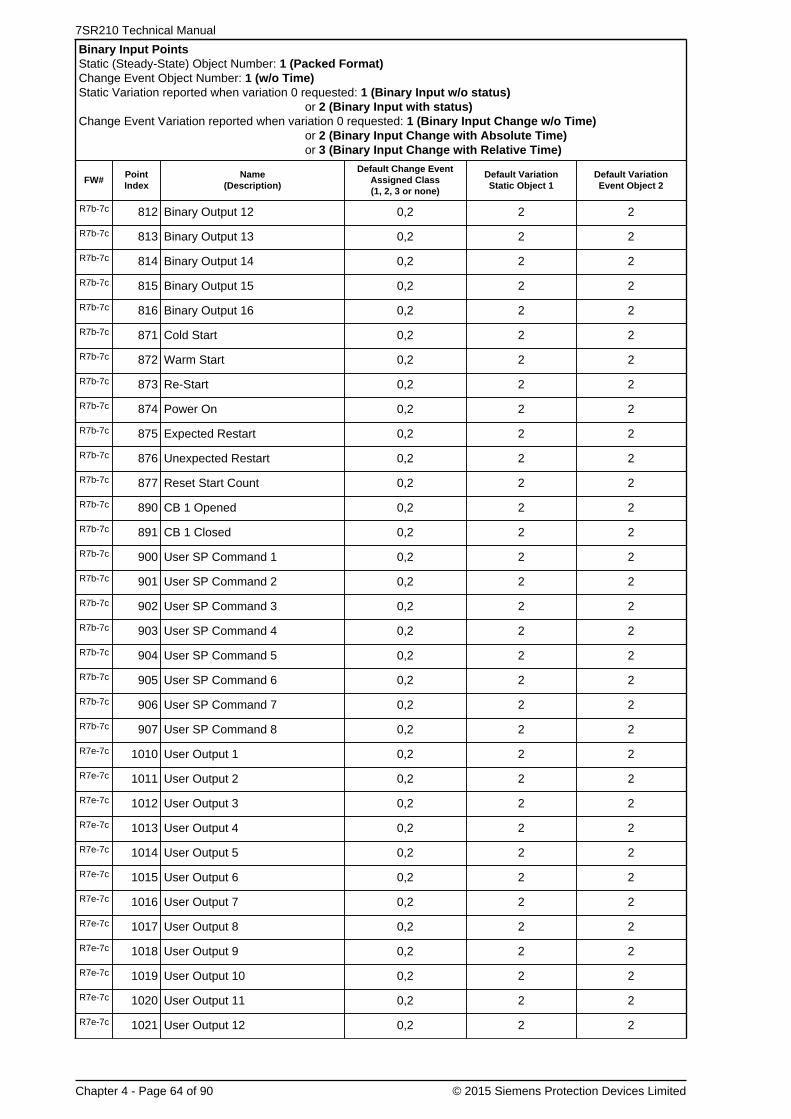
7SR210 Technical Manual
Chapter 4 - Page 64 of 90 © 2015 Siemens Protection Devices Limited
Binary Input PointsStatic (Steady-State) Object Number: 1 (Packed Format)Change Event Object Number: 1 (w/o Time)Static Variation reported when variation 0 requested: 1 (Binary Input w/o status)
or 2 (Binary Input with status)Change Event Variation reported when variation 0 requested: 1 (Binary Input Change w/o Time)
or 2 (Binary Input Change with Absolute Time)or 3 (Binary Input Change with Relative Time)
FW#PointIndex
Name(Description)
Default Change EventAssigned Class(1, 2, 3 or none)
Default VariationStatic Object 1
Default VariationEvent Object 2
R7b-7c 812 Binary Output 12 0,2 2 2
R7b-7c 813 Binary Output 13 0,2 2 2
R7b-7c 814 Binary Output 14 0,2 2 2
R7b-7c 815 Binary Output 15 0,2 2 2
R7b-7c 816 Binary Output 16 0,2 2 2
R7b-7c 871 Cold Start 0,2 2 2
R7b-7c 872 Warm Start 0,2 2 2
R7b-7c 873 Re-Start 0,2 2 2
R7b-7c 874 Power On 0,2 2 2
R7b-7c 875 Expected Restart 0,2 2 2
R7b-7c 876 Unexpected Restart 0,2 2 2
R7b-7c 877 Reset Start Count 0,2 2 2
R7b-7c 890 CB 1 Opened 0,2 2 2
R7b-7c 891 CB 1 Closed 0,2 2 2
R7b-7c 900 User SP Command 1 0,2 2 2
R7b-7c 901 User SP Command 2 0,2 2 2
R7b-7c 902 User SP Command 3 0,2 2 2
R7b-7c 903 User SP Command 4 0,2 2 2
R7b-7c 904 User SP Command 5 0,2 2 2
R7b-7c 905 User SP Command 6 0,2 2 2
R7b-7c 906 User SP Command 7 0,2 2 2
R7b-7c 907 User SP Command 8 0,2 2 2
R7e-7c 1010 User Output 1 0,2 2 2
R7e-7c 1011 User Output 2 0,2 2 2
R7e-7c 1012 User Output 3 0,2 2 2
R7e-7c 1013 User Output 4 0,2 2 2
R7e-7c 1014 User Output 5 0,2 2 2
R7e-7c 1015 User Output 6 0,2 2 2
R7e-7c 1016 User Output 7 0,2 2 2
R7e-7c 1017 User Output 8 0,2 2 2
R7e-7c 1018 User Output 9 0,2 2 2
R7e-7c 1019 User Output 10 0,2 2 2
R7e-7c 1020 User Output 11 0,2 2 2
R7e-7c 1021 User Output 12 0,2 2 2

Chapter 4 - 7SR210 · Data Communications Definitions
© 2015 Siemens Protection Devices Limited Chapter 4 - Page 65 of 90
Binary Input PointsStatic (Steady-State) Object Number: 1 (Packed Format)Change Event Object Number: 1 (w/o Time)Static Variation reported when variation 0 requested: 1 (Binary Input w/o status)
or 2 (Binary Input with status)Change Event Variation reported when variation 0 requested: 1 (Binary Input Change w/o Time)
or 2 (Binary Input Change with Absolute Time)or 3 (Binary Input Change with Relative Time)
FW#PointIndex
Name(Description)
Default Change EventAssigned Class(1, 2, 3 or none)
Default VariationStatic Object 1
Default VariationEvent Object 2
R7e-7c 1022 User Output 13 0,2 2 2
R7e-7c 1023 User Output 14 0,2 2 2
R7e-7c 1024 User Output 15 0,2 2 2
R7e-7c 1025 User Output 16 0,2 2 2
R7e-7c 1026 User Output 17 0,2 2 2
R7e-7c 1027 User Output 18 0,2 2 2
R7e-7c 1028 User Output 19 0,2 2 2
R7e-7c 1029 User Output 20 0,2 2 2
R7e-7c 1030 User Output 21 0,2 2 2
R7e-7c 1031 User Output 22 0,2 2 2
R7e-7c 1032 User Output 23 0,2 2 2
R7e-7c 1033 User Output 24 0,2 2 2
R7e-7c 1034 User Output 25 0,2 2 2
R7e-7c 1035 User Output 26 0,2 2 2
R7e-7c 1036 User Output 27 0,2 2 2
R7e-7c 1037 User Output 28 0,2 2 2
R7e-7c 1038 User Output 29 0,2 2 2
R7e-7c 1039 User Output 30 0,2 2 2
R7e-7c 1040 User Output 31 0,2 2 2
R7e-7c 1041 User Output 32 0,2 2 2
R7f-7d 1061 E/F In 0,2 2 2
R7f-7d 1062 SEF In 0,2 2 2
R7f-7d 1063 CB DBI 0,2 2 2
R7f-7d 1064 CB Travelling 0,2 2 2
R7f-7d 1065 Close CB Failed 0,2 2 2
R7f-7d 1066 Open CB Failed 0,2 2 2
R8a-7f 1067 Start Count Alarm 0,2 2 2
R8a-7f 1068 50AFD PhA 0,2 2 2
R8a-7f 1069 50AFD PhB 0,2 2 2
R8a-7f 1070 50AFD PhC 0,2 2 2
R8a-7f 1071 50AFD 0,2 2 2
R8a-7f 1072 AFD Zone 1 Flash 0,2 2 2
R8a-7f 1073 AFD Zone 1 0,2 2 2
R8a-7f 1074 AFD Zone 2 Flash 0,2 2 2

7SR210 Technical Manual
Chapter 4 - Page 66 of 90 © 2015 Siemens Protection Devices Limited
Binary Input PointsStatic (Steady-State) Object Number: 1 (Packed Format)Change Event Object Number: 1 (w/o Time)Static Variation reported when variation 0 requested: 1 (Binary Input w/o status)
or 2 (Binary Input with status)Change Event Variation reported when variation 0 requested: 1 (Binary Input Change w/o Time)
or 2 (Binary Input Change with Absolute Time)or 3 (Binary Input Change with Relative Time)
FW#PointIndex
Name(Description)
Default Change EventAssigned Class(1, 2, 3 or none)
Default VariationStatic Object 1
Default VariationEvent Object 2
R8a-7f 1075 AFD Zone 2 0,2 2 2
R8a-7f 1076 AFD Zone 3 Flash 0,2 2 2
R8a-7f 1077 AFD Zone 3 0,2 2 2
R8a-7f 1078 AFD Zone 4 Flash 0,2 2 2
R8a-7f 1079 AFD Zone 4 0,2 2 2
R8a-7f 1080 AFD Zone 5 Flash 0,2 2 2
R8a-7f 1081 AFD Zone 5 0,2 2 2
R8a-7f 1082 AFD Zone 6 Flash 0,2 2 2
R8a-7f 1083 AFD Zone 6 0,2 2 2
5.3.2 Double Bit Input Points
The default double bit input event buffer size is set to allow 100 events.
Double bit inputs are by default returned in a class zero interrogation.
Note, not all points listed here apply to all builds of devices.
Double Bit Input PointsStatic (Steady-State) Object Number: 3Change Event Object Number: 4Static Variation reported when variation 0 requested: 1 (Double Bit Input w/o status)
or 2 (Double Bit Input with status)Change Event Variation reported when variation 0 requested: 1 (Double Bit Input Change w/o Time)
or 2 (Double Bit Input Change with Absolute Time)or 3 (Double Bit Input Change with Relative Time)
FW#PointIndex
Name(Description)
Default Change EventAssigned Class(1, 2, 3 or none)
Default VariationStatic Object 3
Default VariationEvent Object 4
R7b-7c 0 CB 1 0,2 1 3
R7b-7c 10 User DP Command 1 0,2 1 3
R7b-7c 11 User DP Command 2 0,2 1 3
R7b-7c 12 User DP Command 3 0,2 1 3
R7b-7c 13 User DP Command 4 0,2 1 3
R7b-7c 14 User DP Command 5 0,2 1 3
R7b-7c 15 User DP Command 6 0,2 1 3
R7b-7c 16 User DP Command 7 0,2 1 3
R7b-7c 17 User DP Command 8 0,2 1 3
5.3.3 Binary Output Status Points and Control Relay Output Blocks

Chapter 4 - 7SR210 · Data Communications Definitions
© 2015 Siemens Protection Devices Limited Chapter 4 - Page 67 of 90
The following table lists both the Binary Output Status Points (Object 10) and the Control Relay Output Blocks (Object12).
While Binary Output Status Points are included here for completeness, they are not often polled by DNP 3.0 Masters.Binary Output Status points are not recommended to be included in class 0 polls.
As an alternative, it is recommended that “actual” status values of Control Relay Output Block points be loopedaround and mapped as Binary Inputs. (The “actual” status value, as opposed to the “commanded” status value, is thevalue of the actuated control. For example, a DNP control command may be blocked through hardware or softwaremechanisms; in this case, the actual status value would indicate the control failed because of the blocking. LoopingControl Relay Output Block actual status values as Binary Inputs has several advantages:
• it allows actual statuses to be included in class 0 polls,
• it allows change event reporting of the actual statuses, which is a more efficient andtime-accurate method of communicating control values,
• and it allows reporting of time-based information associated with controls, including anydelays before controls are actuated, and any durations if the controls are pulsed.
The default select/control buffer size is large enough to hold 10 of the largest select requests possible.
Binary outputs are by default NOT returned in a class zero interrogation.
Note, not all points listed here apply to all builds of devices.
Binary Output Status PointsStatic (Steady-State) Object Number: 10Change Event Object Number: 11Control Relay Output Blocks (CROB) Object Number: 12Binary Output Command Event Object Number: 13Static Variation reported when variation 0 requested: 1 (Binary Output w/o status)
or 2 (Binary Output with status)Change Event Variation reported when variation 0 requested: 1 (Binary Output Event w/o Time)
or 2 (Binary Output Event with Time)Command Event Variation reported when variation 0 requested: 1 (Command Status w/o Time)
or 2 (Command Status with Time)
FW#PointIndex
Name(Description)
DefaultChangeEvent
AssignedClass(1, 2, 3
or none)
DefaultVariation
StaticObject 10
DefaultVariation
EventObject 11
DefaultCommand
EventObject 13Assigned
Class(1, 2, 3
or none)
DefaultVariation
CommandEvent
Object 13
CROBSupportedOperations
DefaultCROB
Operations
1 RL 1 0 2 2 0 1Pulse OnLatch OnClose
Pulse On
2 RL 2 0 2 2 0 1Pulse OnLatch OnClose
Pulse On
3 RL 3 0 2 2 0 1Pulse OnLatch OnClose
Pulse On
4 RL 4 0 2 2 0 1Pulse OnLatch OnClose
Pulse On
5 RL 5 0 2 2 0 1Pulse OnLatch OnClose
Pulse On
6 RL 6 0 2 2 0 1Pulse OnLatch OnClose
Pulse On
7 RL 7 0 2 2 0 1Pulse OnLatch On
Pulse On

7SR210 Technical Manual
Chapter 4 - Page 68 of 90 © 2015 Siemens Protection Devices Limited
Binary Output Status PointsStatic (Steady-State) Object Number: 10Change Event Object Number: 11Control Relay Output Blocks (CROB) Object Number: 12Binary Output Command Event Object Number: 13Static Variation reported when variation 0 requested: 1 (Binary Output w/o status)
or 2 (Binary Output with status)Change Event Variation reported when variation 0 requested: 1 (Binary Output Event w/o Time)
or 2 (Binary Output Event with Time)Command Event Variation reported when variation 0 requested: 1 (Command Status w/o Time)
or 2 (Command Status with Time)
FW#PointIndex
Name(Description)
DefaultChangeEvent
AssignedClass(1, 2, 3
or none)
DefaultVariation
StaticObject 10
DefaultVariation
EventObject 11
DefaultCommand
EventObject 13Assigned
Class(1, 2, 3
or none)
DefaultVariation
CommandEvent
Object 13
CROBSupportedOperations
DefaultCROB
Operations
Close
8 RL 8 0 2 2 0 1Pulse OnLatch OnClose
Pulse On
9 RL 9 0 2 2 0 1Pulse OnLatch OnClose
Pulse On
10 RL 10 0 2 2 0 1Pulse OnLatch OnClose
Pulse On
11 RL 11 0 2 2 0 1Pulse OnLatch OnClose
Pulse On
12 RL 12 0 2 2 0 1Pulse OnLatch OnClose
Pulse On
13 RL 13 0 2 2 0 1Pulse OnLatch OnClose
Pulse On
14 RL 14 0 2 2 0 1Pulse OnLatch OnClose
Pulse On
15 RL 15 0 2 2 0 1Pulse OnLatch OnClose
Pulse On
16 RL 16 0 2 2 0 1Pulse OnLatch OnClose
Pulse On
33LED reset, write onlylocation.
0 2 2 0 1Pulse OnLatch OnClose
Pulse On
34 Settings Group 1 0 2 2 0 1Pulse OnLatch OnClose
Latch On
35 Settings Group 2 0 2 2 0 1Pulse OnLatch OnClose
Latch On
36 Settings Group 3 0 2 2 0 1Pulse OnLatch OnClose
Latch On
37 Settings Group 4 0 2 2 0 1Pulse OnLatch OnClose
Latch On
38 Settings Group 5 0 2 2 0 1Pulse OnLatch OnClose
Latch On

Chapter 4 - 7SR210 · Data Communications Definitions
© 2015 Siemens Protection Devices Limited Chapter 4 - Page 69 of 90
Binary Output Status PointsStatic (Steady-State) Object Number: 10Change Event Object Number: 11Control Relay Output Blocks (CROB) Object Number: 12Binary Output Command Event Object Number: 13Static Variation reported when variation 0 requested: 1 (Binary Output w/o status)
or 2 (Binary Output with status)Change Event Variation reported when variation 0 requested: 1 (Binary Output Event w/o Time)
or 2 (Binary Output Event with Time)Command Event Variation reported when variation 0 requested: 1 (Command Status w/o Time)
or 2 (Command Status with Time)
FW#PointIndex
Name(Description)
DefaultChangeEvent
AssignedClass(1, 2, 3
or none)
DefaultVariation
StaticObject 10
DefaultVariation
EventObject 11
DefaultCommand
EventObject 13Assigned
Class(1, 2, 3
or none)
DefaultVariation
CommandEvent
Object 13
CROBSupportedOperations
DefaultCROB
Operations
39 Settings Group 6 0 2 2 0 1Pulse OnLatch OnClose
Latch On
40 Settings Group 7 0 2 2 0 1Pulse OnLatch OnClose
Latch On
41 Settings Group 8 0 2 2 0 1Pulse OnLatch OnClose
Latch On
42 Auto-reclose on/off 0 2 2 0 1
Pulse OnPulse OffLatch OnLatch OffCloseTrip
Pulse OnPulse OffLatch OnLatch Off
43 Hot Line Working on/off 0 2 2 0 1
Pulse OnPulse OffLatch OnLatch OffCloseTrip
Pulse OnPulse OffLatch OnLatch Off
44 E/F off/on 0 2 2 0 1
Pulse OnPulse OffLatch OnLatch OffCloseTrip
Pulse OnPulse OffLatch OnLatch Off
45 SEF off/on 0 2 2 0 1
Pulse OnPulse OffLatch OnLatch OffCloseTrip
Pulse OnPulse OffLatch OnLatch Off
46 Inst Protection off/on 0 2 2 0 1
Pulse OnPulse OffLatch OnLatch OffCloseTrip
Pulse OnPulse OffLatch OnLatch Off
48Reset CB Total TripCount, write onlylocation.
0 2 2 0 1Pulse OnLatch OnClose
Pulse On
49Reset CB Delta TripCount, write onlylocation.
0 2 2 0 1Pulse OnLatch OnClose
Pulse On
50Reset CB Count To ARBlock, write only location.
0 2 2 0 1Pulse OnLatch On
Pulse On

7SR210 Technical Manual
Chapter 4 - Page 70 of 90 © 2015 Siemens Protection Devices Limited
Binary Output Status PointsStatic (Steady-State) Object Number: 10Change Event Object Number: 11Control Relay Output Blocks (CROB) Object Number: 12Binary Output Command Event Object Number: 13Static Variation reported when variation 0 requested: 1 (Binary Output w/o status)
or 2 (Binary Output with status)Change Event Variation reported when variation 0 requested: 1 (Binary Output Event w/o Time)
or 2 (Binary Output Event with Time)Command Event Variation reported when variation 0 requested: 1 (Command Status w/o Time)
or 2 (Command Status with Time)
FW#PointIndex
Name(Description)
DefaultChangeEvent
AssignedClass(1, 2, 3
or none)
DefaultVariation
StaticObject 10
DefaultVariation
EventObject 11
DefaultCommand
EventObject 13Assigned
Class(1, 2, 3
or none)
DefaultVariation
CommandEvent
Object 13
CROBSupportedOperations
DefaultCROB
Operations
Close
51Reset CB FrequentOps Count, write onlylocation.
0 2 2 0 1Pulse OnLatch OnClose
Pulse On
53 Reset I^2t CB Wear 0 2 2 0 1Pulse OnLatch OnClose
Pulse On
54 CB 1 0 2 2 0 1
Pulse OnPulse OffLatch OnLatch OffCloseTrip
Pulse OnPulse OffLatch OnLatch Off
55CB 1 Trip & Reclose,write only location.
0 2 2 0 1Pulse OnLatch OnClose
Pulse On
56CB 1 Trip & Lockout,write only location.
0 2 2 0 1Pulse OnLatch OnClose
Pulse On
59Demand metering reset,write only location.
0 2 2 0 1Pulse OnLatch OnClose
Pulse On
88 Remote mode 0 2 2 0 1Pulse OnLatch OnClose
Pulse On
89 Service mode 0 2 2 0 1Pulse OnLatch OnClose
Pulse On
90 Local mode 0 2 2 0 1Pulse OnLatch OnClose
Pulse On
91 Local & Remote 0 2 2 0 1Pulse OnLatch OnClose
Pulse On
R7b-7c 94Reset CB Phase ATrip Count, write onlylocation.
0 2 2 0 1Pulse OnLatch OnClose
Pulse On
R7b-7c 95Reset CB Phase BTrip Count, write onlylocation.
0 2 2 0 1Pulse OnLatch OnClose
Pulse On
R7b-7c 96Reset CB Phase CTrip Count, write onlylocation.
0 2 2 0 1Pulse OnLatch OnClose
Pulse On
R7b-7c 97Reset CB EF Trip Count,write only location.
0 2 2 0 1Pulse OnLatch OnClose
Pulse On
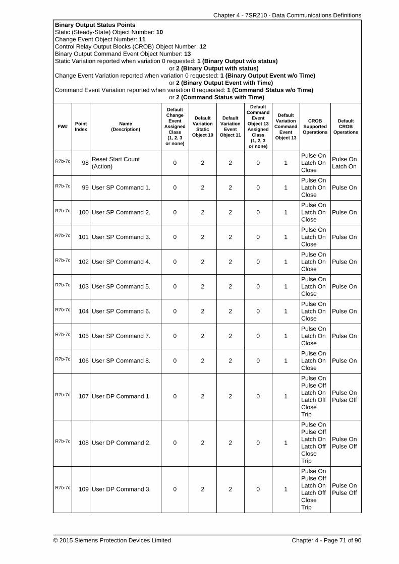
Chapter 4 - 7SR210 · Data Communications Definitions
© 2015 Siemens Protection Devices Limited Chapter 4 - Page 71 of 90
Binary Output Status PointsStatic (Steady-State) Object Number: 10Change Event Object Number: 11Control Relay Output Blocks (CROB) Object Number: 12Binary Output Command Event Object Number: 13Static Variation reported when variation 0 requested: 1 (Binary Output w/o status)
or 2 (Binary Output with status)Change Event Variation reported when variation 0 requested: 1 (Binary Output Event w/o Time)
or 2 (Binary Output Event with Time)Command Event Variation reported when variation 0 requested: 1 (Command Status w/o Time)
or 2 (Command Status with Time)
FW#PointIndex
Name(Description)
DefaultChangeEvent
AssignedClass(1, 2, 3
or none)
DefaultVariation
StaticObject 10
DefaultVariation
EventObject 11
DefaultCommand
EventObject 13Assigned
Class(1, 2, 3
or none)
DefaultVariation
CommandEvent
Object 13
CROBSupportedOperations
DefaultCROB
Operations
R7b-7c 98Reset Start Count(Action)
0 2 2 0 1Pulse OnLatch OnClose
Pulse OnLatch On
R7b-7c 99 User SP Command 1. 0 2 2 0 1Pulse OnLatch OnClose
Pulse On
R7b-7c 100 User SP Command 2. 0 2 2 0 1Pulse OnLatch OnClose
Pulse On
R7b-7c 101 User SP Command 3. 0 2 2 0 1Pulse OnLatch OnClose
Pulse On
R7b-7c 102 User SP Command 4. 0 2 2 0 1Pulse OnLatch OnClose
Pulse On
R7b-7c 103 User SP Command 5. 0 2 2 0 1Pulse OnLatch OnClose
Pulse On
R7b-7c 104 User SP Command 6. 0 2 2 0 1Pulse OnLatch OnClose
Pulse On
R7b-7c 105 User SP Command 7. 0 2 2 0 1Pulse OnLatch OnClose
Pulse On
R7b-7c 106 User SP Command 8. 0 2 2 0 1Pulse OnLatch OnClose
Pulse On
R7b-7c 107 User DP Command 1. 0 2 2 0 1
Pulse OnPulse OffLatch OnLatch OffCloseTrip
Pulse OnPulse Off
R7b-7c 108 User DP Command 2. 0 2 2 0 1
Pulse OnPulse OffLatch OnLatch OffCloseTrip
Pulse OnPulse Off
R7b-7c 109 User DP Command 3. 0 2 2 0 1
Pulse OnPulse OffLatch OnLatch OffCloseTrip
Pulse OnPulse Off

7SR210 Technical Manual
Chapter 4 - Page 72 of 90 © 2015 Siemens Protection Devices Limited
Binary Output Status PointsStatic (Steady-State) Object Number: 10Change Event Object Number: 11Control Relay Output Blocks (CROB) Object Number: 12Binary Output Command Event Object Number: 13Static Variation reported when variation 0 requested: 1 (Binary Output w/o status)
or 2 (Binary Output with status)Change Event Variation reported when variation 0 requested: 1 (Binary Output Event w/o Time)
or 2 (Binary Output Event with Time)Command Event Variation reported when variation 0 requested: 1 (Command Status w/o Time)
or 2 (Command Status with Time)
FW#PointIndex
Name(Description)
DefaultChangeEvent
AssignedClass(1, 2, 3
or none)
DefaultVariation
StaticObject 10
DefaultVariation
EventObject 11
DefaultCommand
EventObject 13Assigned
Class(1, 2, 3
or none)
DefaultVariation
CommandEvent
Object 13
CROBSupportedOperations
DefaultCROB
Operations
R7b-7c 110 User DP Command 4. 0 2 2 0 1
Pulse OnPulse OffLatch OnLatch OffCloseTrip
Pulse OnPulse Off
R7b-7c 111 User DP Command 5. 0 2 2 0 1
Pulse OnPulse OffLatch OnLatch OffCloseTrip
Pulse OnPulse Off
R7b-7c 112 User DP Command 6. 0 2 2 0 1
Pulse OnPulse OffLatch OnLatch OffCloseTrip
Pulse OnPulse Off
R7b-7c 113 User DP Command 7. 0 2 2 0 1
Pulse OnPulse OffLatch OnLatch OffCloseTrip
Pulse OnPulse Off
R7b-7c 114 User DP Command 8. 0 2 2 0 1
Pulse OnPulse OffLatch OnLatch OffCloseTrip
Pulse OnPulse Off
R7b-7c 115 CB-1 Open 0 2 2 0 1Pulse OnLatch OnClose
Pulse OnLatch On
R7b-7c 116 CB-1 Close 0 2 2 0 1Pulse OnLatch OnClose
Pulse OnLatch On
5.3.4 Counters
The following table lists both Binary Counters (Object 20) and Frozen Counters (Object 21). When a freeze functionis performed on a Binary Counter point, the frozen value is available in the corresponding Frozen Counter point. Thedefault Binary Counter and Frozen Counter event buffer sizes are set to 30.
The “Default Deadband,” and the “Default Change Event Assigned Class” columns are used to represent the absoluteamount by which the point must change before a Counter change event will be generated, and once generated inwhich class poll (1, 2, 3, or none) will the change event be reported.
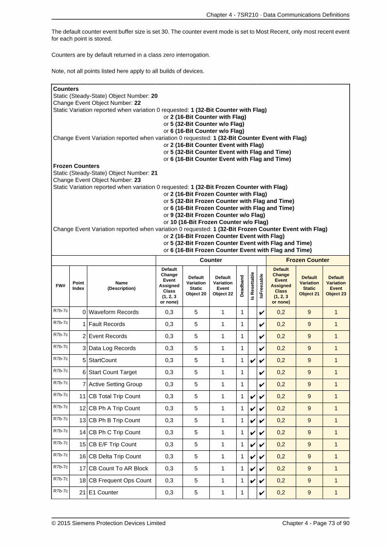
Chapter 4 - 7SR210 · Data Communications Definitions
© 2015 Siemens Protection Devices Limited Chapter 4 - Page 73 of 90
The default counter event buffer size is set 30. The counter event mode is set to Most Recent, only most recent eventfor each point is stored.
Counters are by default returned in a class zero interrogation.
Note, not all points listed here apply to all builds of devices.
CountersStatic (Steady-State) Object Number: 20Change Event Object Number: 22Static Variation reported when variation 0 requested: 1 (32-Bit Counter with Flag)
or 2 (16-Bit Counter with Flag)or 5 (32-Bit Counter w/o Flag)or 6 (16-Bit Counter w/o Flag)
Change Event Variation reported when variation 0 requested: 1 (32-Bit Counter Event with Flag)or 2 (16-Bit Counter Event with Flag)or 5 (32-Bit Counter Event with Flag and Time)or 6 (16-Bit Counter Event with Flag and Time)
Frozen CountersStatic (Steady-State) Object Number: 21Change Event Object Number: 23Static Variation reported when variation 0 requested: 1 (32-Bit Frozen Counter with Flag)
or 2 (16-Bit Frozen Counter with Flag)or 5 (32-Bit Frozen Counter with Flag and Time)or 6 (16-Bit Frozen Counter with Flag and Time)or 9 (32-Bit Frozen Counter w/o Flag)or 10 (16-Bit Frozen Counter w/o Flag)
Change Event Variation reported when variation 0 requested: 1 (32-Bit Frozen Counter Event with Flag)or 2 (16-Bit Frozen Counter Event with Flag)or 5 (32-Bit Frozen Counter Event with Flag and Time)or 6 (16-Bit Frozen Counter Event with Flag and Time)
Counter Frozen Counter
FW#PointIndex
Name(Description)
DefaultChangeEvent
AssignedClass(1, 2, 3
or none)
DefaultVariation
StaticObject 20
DefaultVariation
EventObject 22 D
ead
ban
d
Is R
eset
tab
le
IsF
reez
able
DefaultChangeEvent
AssignedClass(1, 2, 3
or none)
DefaultVariation
StaticObject 21
DefaultVariation
EventObject 23
R7b-7c 0 Waveform Records 0,3 5 1 1 0,2 9 1
R7b-7c 1 Fault Records 0,3 5 1 1 0,2 9 1
R7b-7c 2 Event Records 0,3 5 1 1 0,2 9 1
R7b-7c 3 Data Log Records 0,3 5 1 1 0,2 9 1
R7b-7c 5 StartCount 0,3 5 1 1 0,2 9 1
R7b-7c 6 Start Count Target 0,3 5 1 1 0,2 9 1
R7b-7c 7 Active Setting Group 0,3 5 1 1 0,2 9 1
R7b-7c 11 CB Total Trip Count 0,3 5 1 1 0,2 9 1
R7b-7c 12 CB Ph A Trip Count 0,3 5 1 1 0,2 9 1
R7b-7c 13 CB Ph B Trip Count 0,3 5 1 1 0,2 9 1
R7b-7c 14 CB Ph C Trip Count 0,3 5 1 1 0,2 9 1
R7b-7c 15 CB E/F Trip Count 0,3 5 1 1 0,2 9 1
R7b-7c 16 CB Delta Trip Count 0,3 5 1 1 0,2 9 1
R7b-7c 17 CB Count To AR Block 0,3 5 1 1 0,2 9 1
R7b-7c 18 CB Frequent Ops Count 0,3 5 1 1 0,2 9 1
R7b-7c 21 E1 Counter 0,3 5 1 1 0,2 9 1

7SR210 Technical Manual
Chapter 4 - Page 74 of 90 © 2015 Siemens Protection Devices Limited
CountersStatic (Steady-State) Object Number: 20Change Event Object Number: 22Static Variation reported when variation 0 requested: 1 (32-Bit Counter with Flag)
or 2 (16-Bit Counter with Flag)or 5 (32-Bit Counter w/o Flag)or 6 (16-Bit Counter w/o Flag)
Change Event Variation reported when variation 0 requested: 1 (32-Bit Counter Event with Flag)or 2 (16-Bit Counter Event with Flag)or 5 (32-Bit Counter Event with Flag and Time)or 6 (16-Bit Counter Event with Flag and Time)
Frozen CountersStatic (Steady-State) Object Number: 21Change Event Object Number: 23Static Variation reported when variation 0 requested: 1 (32-Bit Frozen Counter with Flag)
or 2 (16-Bit Frozen Counter with Flag)or 5 (32-Bit Frozen Counter with Flag and Time)or 6 (16-Bit Frozen Counter with Flag and Time)or 9 (32-Bit Frozen Counter w/o Flag)or 10 (16-Bit Frozen Counter w/o Flag)
Change Event Variation reported when variation 0 requested: 1 (32-Bit Frozen Counter Event with Flag)or 2 (16-Bit Frozen Counter Event with Flag)or 5 (32-Bit Frozen Counter Event with Flag and Time)or 6 (16-Bit Frozen Counter Event with Flag and Time)
Counter Frozen Counter
FW#PointIndex
Name(Description)
DefaultChangeEvent
AssignedClass(1, 2, 3
or none)
DefaultVariation
StaticObject 20
DefaultVariation
EventObject 22 D
ead
ban
d
Is R
eset
tab
le
IsF
reez
able
DefaultChangeEvent
AssignedClass(1, 2, 3
or none)
DefaultVariation
StaticObject 21
DefaultVariation
EventObject 23
R7b-7c 22 E2 Counter 0,3 5 1 1 0,2 9 1
R7b-7c 23 E3 Counter 0,3 5 1 1 0,2 9 1
R7b-7c 24 E4 Counter 0,3 5 1 1 0,2 9 1
R7b-7c 25 E5 Counter 0,3 5 1 1 0,2 9 1
R7b-7c 26 E6 Counter 0,3 5 1 1 0,2 9 1
R7b-7c 27 E7 Counter 0,3 5 1 1 0,2 9 1
R7b-7c 28 E8 Counter 0,3 5 1 1 0,2 9 1
R7b-7c 29 E9 Counter 0,3 5 1 1 0,2 9 1
R7b-7c 30 E10 Counter 0,3 5 1 1 0,2 9 1
R7b-7c 31 E11 Counter 0,3 5 1 1 0,2 9 1
R7b-7c 32 E12 Counter 0,3 5 1 1 0,2 9 1
R7b-7c 33 E13 Counter 0,3 5 1 1 0,2 9 1
R7b-7c 34 E14 Counter 0,3 5 1 1 0,2 9 1
R7b-7c 35 E15 Counter 0,3 5 1 1 0,2 9 1
R7b-7c 36 E16 Counter 0,3 5 1 1 0,2 9 1
5.3.5 Analog Inputs
The following table lists Analog Inputs (Object 30). It is important to note that 16-bit and 32-bit variations of AnalogInputs, Analog Output Control Blocks, and Analog Output Statuses are transmitted through DNP as signed numbers.
The “Default Deadband,” and the “Default Change Event Assigned Class” columns are used to represent the absoluteamount by which the point must change before an Analog change event will be generated, and once generated inwhich class poll (1, 2, 3, or none) will the change event be reported.

Chapter 4 - 7SR210 · Data Communications Definitions
© 2015 Siemens Protection Devices Limited Chapter 4 - Page 75 of 90
The default analog input event buffer size is set 30. The analog input event mode is set to Most Recent, only mostrecent event for each point is stored.
Analog inputs are by default returned in a class zero interrogation.
Note, not all points listed here apply to all builds of devices.
Analog InputsStatic (Steady-State) Object Number: 30Change Event Object Number: 32Analog Input Deadband: 34Static Variation reported when variation 0 requested: 1 (32-Bit Analog Input with Flag)
or 2 (16-Bit Analog Input with Flag)or 3 (32-Bit Analog Input w/o Flag)or 4 (16-Bit Analog Input w/o Flag)or 5 (Single Precision, floating point Analog Input with Flag)
Change Event Variation reported when variation 0 requested: 1 (32-Bit Analog Change Event w/o Time)or 2 (16-Bit Analog Input w/o Time)or 3 (32-Bit Analog Input with Time)or 4 (16-Bit Analog Input with Time)or 5 (Single Precision, floating point Analog Input w/o Time)or 7 (Single Precision, floating point Analog Input with Time)
Analog Input Reporting Deadband Variation reported when variation 0 requested: 1 (16-Bit)or 2 (32-Bit)or 3 (Single Precision, floating point)
FW#PointIndex
Name(Description)
DefaultChange Event
Assigned Class(1, 2, 3 or none)
DefaultVariation
StaticObject 30
DefaultVariation
EventObject 32
DefaultMultiplier
DefaultDeadband
0 Frequency 0,3 2 4 100.000 1.000
31 Ia Primary 0,3 2 4 1.000 100.000
32 Ib Primary 0,3 2 4 1.000 100.000
33 Ic Primary 0,3 2 4 1.000 100.000
34 Ia Secondary 0,3 2 4 100.000 0.100
35 Ib Secondary 0,3 2 4 100.000 0.100
36 Ic Secondary 0,3 2 4 100.000 0.100
37 Ia Nominal 0,3 2 4 100.000 0.100
38 Ib Nominal 0,3 2 4 100.000 0.100
39 Ic Nominal 0,3 2 4 100.000 0.100
43 In Primary 0,3 2 4 1.000 100.000
44 In Secondary 0,3 2 4 100.000 0.100
45 In Nominal 0,3 2 4 100.000 0.100
46 Ig Primary 0,3 2 4 1.000 100.000
47 Ig Secondary 0,3 2 4 1000.000 0.100
48 Ig Nominal 0,3 2 4 1000.000 0.100
51 Izps Nominal 0,3 2 4 100.000 0.100
52 Ipps Nominal 0,3 2 4 100.000 0.100
53 Inps Nominal 0,3 2 4 100.000 0.100
81 Thermal Status Ph A 0,1 4 4 100.000 1.000
82 Thermal Status Ph B 0,1 4 4 100.000 1.000
83 Thermal Status Ph C 0,1 4 4 100.000 1.000
95 Active Setting Group 0,3 2 4 1.000 1.000
108 I Phase A Max 0,3 2 4 1.000 100.000
109 I Phase B Max 0,3 2 4 1.000 100.000
110 I Phase C Max 0,3 2 4 1.000 100.000
113 Ig Max 0,3 2 4 1.000 100.000

7SR210 Technical Manual
Chapter 4 - Page 76 of 90 © 2015 Siemens Protection Devices Limited
Analog InputsStatic (Steady-State) Object Number: 30Change Event Object Number: 32Analog Input Deadband: 34Static Variation reported when variation 0 requested: 1 (32-Bit Analog Input with Flag)
or 2 (16-Bit Analog Input with Flag)or 3 (32-Bit Analog Input w/o Flag)or 4 (16-Bit Analog Input w/o Flag)or 5 (Single Precision, floating point Analog Input with Flag)
Change Event Variation reported when variation 0 requested: 1 (32-Bit Analog Change Event w/o Time)or 2 (16-Bit Analog Input w/o Time)or 3 (32-Bit Analog Input with Time)or 4 (16-Bit Analog Input with Time)or 5 (Single Precision, floating point Analog Input w/o Time)or 7 (Single Precision, floating point Analog Input with Time)
Analog Input Reporting Deadband Variation reported when variation 0 requested: 1 (16-Bit)or 2 (32-Bit)or 3 (Single Precision, floating point)
FW#PointIndex
Name(Description)
DefaultChange Event
Assigned Class(1, 2, 3 or none)
DefaultVariation
StaticObject 30
DefaultVariation
EventObject 32
DefaultMultiplier
DefaultDeadband
135 CB Total Trip Count 0,3 1 3 1.000 1.000
136 CB Delta Trip Count 0,3 1 3 1.000 1.000
137 CB Count To AR Block 0,3 1 3 1.000 1.000
138 CB Frequent Ops Count 0,3 1 3 1.000 1.000
R7b-7c 165 Ia Last Trip 0,3 1 3 1.000 Disabled
R7b-7c 166 Ib Last Trip 0,3 1 3 1.000 Disabled
R7b-7c 167 Ic Last Trip 0,3 1 3 1.000 Disabled
R7b-7c 171 In Last Trip 0,3 1 3 1.000 Disabled
R7b-7c 172 Ig Last Trip 0,3 1 3 1.000 Disabled
R7b-7c 180 CB Ph A Trip Count 0,3 1 3 1.000 1.000
R7b-7c 181 CB Ph B Trip Count 0,3 1 3 1.000 1.000
R7b-7c 182 CB Ph C Trip Count 0,3 1 3 1.000 1.000
R7b-7c 183 CB E/F Trip Count 0,3 1 3 1.000 1.000
R7b-7c 184 CB Wear A 0,3 1 3 0.000 1000000.000
R7b-7c 185 CB Wear B 0,3 1 3 0.000 1000000.000
R7b-7c 186 CB Wear C 0,3 1 3 0.000 1000000.000
R7b-7c 187 CB Wear A Remaining 0,3 1 3 1.000 1.000
R7b-7c 188 CB Wear B Remaining 0,3 1 3 1.000 1.000
R7b-7c 189 CB Wear C Remaining 0,3 1 3 1.000 1.000
R7b-7c 190 CB Wear Minimum 0,3 1 3 1.000 1.000
R7b-7c 196 Frequency Max 0,3 2 4 100.000 1.000
R7f-7d 330 CB Trip Time Meter 0,3 2 4 1000.000 0.010
5.4 Additional Settings
The following relay settings are provided for configuration of the DNP 3.0 implementation when available and arecommon to all ports using this protocol.

Chapter 4 - 7SR210 · Data Communications Definitions
© 2015 Siemens Protection Devices Limited Chapter 4 - Page 77 of 90
Setting Name Range/Options Default Setting Notes
UnsolicitedMode
DISABLED, ENABLED DISABLED As Required
Setting is only visiblewhen any portProtocol is set toDNP3.
DestinationAddress
0 - 65534 0 As Required
Setting is onlyvisible when DNP3Unsolicited Eventsset to Enabled.
DNP3ApplicationTimeout
5, 6 ... 299, 300 10s As Required
Setting is only visiblewhen any portProtocol is set toDNP3.

7SR210 Technical Manual
Chapter 4 - Page 78 of 90 © 2015 Siemens Protection Devices Limited

Chapter 4 - 7SR210 · Data Communications Definitions
© 2015 Siemens Protection Devices Limited Chapter 4 - Page 79 of 90
6. Not Applicable
This Page Intentionally Left Blank.

7SR210 Technical Manual
Chapter 4 - Page 80 of 90 © 2015 Siemens Protection Devices Limited

Chapter 4 - 7SR210 · Data Communications Definitions
© 2015 Siemens Protection Devices Limited Chapter 4 - Page 81 of 90
7. IEC61850 Protocol Support7.1 Introduction
The relay can optionally be provided with IEC61850 comms.
For further details refer to the following publications:
• Model Implementation Conformance Statement (MICS)
• Protocol Implementation Conformance Statement (PICS)
• Protocol Implementation Extra Information for Testing (PIXIT)

7SR210 Technical Manual
Chapter 4 - Page 82 of 90 © 2015 Siemens Protection Devices Limited

Chapter 4 - 7SR210 · Data Communications Definitions
© 2015 Siemens Protection Devices Limited Chapter 4 - Page 83 of 90
8. Serial Modems
8.1 Introduction
The communications interface has been designed to allow data transfer via modems. A suitable Modem can beconnected directly to the Relay's serial interface, for example RS232, RS485 or fibre-optic port where fitted.
8.2 Connecting a Modem to the Relay(s)
RS232C defines devices as being either Data Terminal Equipment (DTE) e.g. computers, or data CommunicationsEquipment (DCE), e.g. modems, where one is designed to be connected to the other.
The optional RS232 port of the Relay is wired as a DTE device and can therefore be connected directly to a Modem.
The 7XV5652 RS232 fibre-optic converter is wired as a DCE device, the same as a Modem. Where two DCE devicese.g. the modem and the fibre-optic converter are being connected together a null terminal connector is required whichswitches various control lines. The fibre-optic converter is then connected to the relay Network Tx to Relay Rx andNetwork Rx to Relay Tx.
8.3 Setting the Remote Modem
The exact settings of the modem are dependent on the type of modem. Although most modems support the basicHayes “AT” command format, different manufacturers use different commands for the same functions. In addition,some modems use DIP switches to set parameters, others are entirely software configured.
Before applying settings, the modem's factory default settings should be applied, to ensure it is in a known state.
Several factors must be considered to allow remote dialling to the relays. The first is that the modem at the remoteend must be configured as auto answer. This will allow it to initiate communications with the relays. Next, the usershould set the data configuration at the local port, i.e. baud rate and parity, so that communication will be at the samerate and format as that set on the relay and the error correction is disabled.
Auto-answer usually requires two parameters to be set. The auto-answer setting should be switched on and thenumber of rings after which it will answer. The Data Terminal Ready (DTR) settings should be forced on. This tellsthe modem that the device connected to it is ready to receive data.
The parameters of the modem's RS232C port are set to match those set on the relay, set baud rate and parity tobe the same as the settings on the relay and number of data bits to be 8 and stop bits 1. Note, although the devicemay be able to communicate with the modem at, for example, 19200 bps, the modem may only be able to transmitover the telephone lines at 14400 bps. Therefore, a baud rate setting on which the modem can transmit should bechosen. In the aboveexample, a baud rate of 9600 should be chosen.
As the modems are required to be transparent, simply passing on the data sent from the controller to the device andvice versa, error correction and buffering is turned off.
Finally, the settings selected for configuration should be stored in the modem's memory for power on defaults.
8.4 Connecting to the Remote Modem
Once the remote modem has been configured correctly, it should be possible to make connection to the relay.
Where a “dial-up” modem system is installed the settings on the remote modem are fixed so the local modem shouldnegotiate with it on connection, choosing suitable matching settings. Where this is not possible the local modemshould be set with settings equivalent to those of the remote modem as described above.

7SR210 Technical Manual
Chapter 4 - Page 84 of 90 © 2015 Siemens Protection Devices Limited

Chapter 4 - 7SR210 · Data Communications Definitions
© 2015 Siemens Protection Devices Limited Chapter 4 - Page 85 of 90
9. Configuration
The data points and control features which are possible within the relay is fixed and can be transmitted overthe communication channel(s) protocols in the default format described earlier in this document. The default datatransmitted is not always directly compatible with the needs of the substation control system and will require sometailoring; this can be done by the user with the Reydisp software Communications Editor tool.
The Communications Editor is provided to allow its users to configure the Communication Protocol's Files in Reyrollebrand Relays manufactured by Siemens Protection Devices Limited (SPDL).
The editor supports configuring DNP3, IEC60870-5-103, IEC60870-5-101 and MODBUS protocols.
The editor allows configuration files to be retrieved from the relay, edited, and then uploaded back to the relay. Filesmay also be saved to and loaded from disc to work offline. The protocols will be stored in a Reyrolle Protection DeviceComms file (RPDC), which will be stored locally, so that the editor can be used when the relay is not connected.
DNP3
The tool will allow:
• Data Points to be enabled or disabled.
• Changing the point numbers for the Binary Inputs, Double Bit Inputs, Binary Outputs,Counters and Analogue Inputs.
• Changing their assigned class and static and event variants.
• Specifying inclusion in a Class 0 poll.
• Setting Binary points to be inverted before transmission.
• Setting the Control Relay Output Block (CROB) commands that can be used with aBinary Output (Object 12).
• Specifying a dead-band outside which Analogue Events will be generated.
• Specifying a multiplier that will be applied to an analogue value before transmission.
• Configuring a Counter's respective Frozen Counter.
IEC60870-5-103
The tool will allow:
• Data Points to be enabled or disabled.
• Changing the point numbers Function Type (FUN) and Information (INF), returned byeach point.
• Changing the text returned to Reydisp for display in its event viewer.
MODBUS
Note, as MODBUS points are polled they do not need to be enabled or disabled.
The tool will allow:

7SR210 Technical Manual
Chapter 4 - Page 86 of 90 © 2015 Siemens Protection Devices Limited
• Changing the Addresses for the Coils, Inputs and Registers.
• Changing the format of the instrument returned in a register, e.g. 16 or 32 bit.
• Specifying a multiplier that will be applied to an analogue value before transmission.
The user can check if the relay contains user configured communication files via a meter in the relay menus. Pressingthe Enter and down arrow buttons on the fascia, then scrolling down, the number of files stored in the relay isdisplayed. The file name can also be viewed by pressing the Cancel and Test/Reset buttons together when in therelay Instruments menu. The user must ensure when naming the file, they use a unique file name including theversion number.
Please refer to the Communications Editor User Guide for further guidance.

Chapter 4 - 7SR210 · Data Communications Definitions
© 2015 Siemens Protection Devices Limited Chapter 4 - Page 87 of 90
10. Glossary
Baud Rate
Data transmission speed.
Bit
The smallest measure of computer data.
Bits Per Second (bps)
Measurement of data transmission speed.
Data Bits
A number of bits containing the data. Sent after the start bit.
Data Echo
When connecting relays in an optical ring architecture, the data must be passed from one relay to the next, thereforewhen connecting in this method all relays must have the Data Echo ON.
EN100
Siemens' Ethernet communications module supporting IEC61850, available in optical and electrical versions.
Ethernet
A computer networking technology.
Full-Duplex Asynchronous Communications
Communications in two directions simultaneously.
Half-Duplex Asynchronous Communications
Communications in two directions, but only one at a time.
Hayes “AT”
Modem command set developed by Hayes Microcomputer products, Inc.
LAN
Local Area Network. A computer network covering a small geographic area.
LC
Fibre optic connector type designed by Lucent Technologies, Inc.
Line Idle
Determines when the device is not communicating if the idle state transmits light.
Modem
MOdulator / DEModulator device for connecting computer equipment to a telephone line.
Parity
Method of error checking by counting the value of the bits in a sequence, and adding a parity bit to make the outcome,for example, even.
Parity Bit
Bit used for implementing parity checking. Sent after the data bits.
RS232C
Serial Communications Standard. Electronic Industries Association Recommended Standard Number 232, RevisionC.
RS485
Serial Communications Standard. Electronic Industries Association Recommended Standard Number 485.

7SR210 Technical Manual
Chapter 4 - Page 88 of 90 © 2015 Siemens Protection Devices Limited
Start Bit
Bit (logical 0) sent to signify the start of a byte during data transmission.
Stop Bit
Bit (logical 1) sent to signify the end.
USB
Universal Serial Bus standard for the transfer of data.
WAN
Wide Area Network. A computer network covering a large geographic area.

Chapter 4 - 7SR210 · Data Communications Definitions
© 2015 Siemens Protection Devices Limited Chapter 4 - Page 89 of 90
Appendix 1
The operating mode of the device is set via the setting, or through a command sent to a communications port. Thereare four options; Local, Remote, Local or Remote and Service.
The following table illustrates whether a function is Enabled () or Disabled () in each mode.
Operation ModeFunction
Local Remote Service
Control
Com1 when Com1-Mode = Local when Com1-Mode = Remote
Com2 (USB) when Com2-Mode = Local when Com2-Mode = Remote
Com3 when Com3-Mode = Local when Com3-Mode = Remote
Com4 when Com4-Mode = Local when Com4-Mode = Remote
Fascia (Control Mode)
Function Key (n) when F Key(n) Mode = Remote
Binary Input (n) when BI (n) Mode = Local when BI (n) Mode = Remote
Binary Outputs
Reporting
Spontaneous
IEC
DNP3
General Interrogation
IEC
DNP3
MODBUS
Change Settings
Com1 when Com1-Mode = Local when Com1-Mode = Remote
Com2 (USB) when Com2-Mode = Local when Com2-Mode = Remote
Com3 when Com3-Mode = Local when Com3-Mode = Remote
Com4 when Com4-Mode = Local when Com4-Mode = Remote
Fascia
Historical Information
Waveform Records
Event Records
Fault Information
Setting Information
Fig. A1 Operating Mode Table

7SR210 Technical Manual
Chapter 4 - Page 90 of 90 © 2015 Siemens Protection Devices Limited
Siemens Protection Devices Ltd. (SPDL)
P.O. Box 8
Hebburn
Tyne and Wear
NE31 1TZ
United Kingdom
For enquiries please contact our Customer Support Centre
Tel.: +49 180/524 8437 (24hrs)
Fax.: +49 180/524 2471
E-Mail:[email protected]
www.siemens.com/reyrolle
Template Revision 12.
Chapter 4 - 7SR220 · Data Communications Definitions
The copyright and other intellectual property rights in this document, and in any model or article produced from it(and including any registered or unregistered design rights) are the property of Siemens Protection Devices Limited.No part of this document shall be reproduced or modified or stored in another form, in any data retrieval system,without the permission of Siemens Protection Devices Limited, nor shall any model or article be reproduced from thisdocument unless Siemens Protection Devices Limited consent.
While the information and guidance given in this document is believed to be correct, no liability shall be accepted forany loss or damage caused by any error or omission, whether such error or omission is the result of negligence orany other cause. Any and all such liability is disclaimed.
© 2015 Siemens Protection Devices Limited
7SR220
7SR220x-2xAxx-0EA0Directional Overcurrent Relay
Document Release HistoryThis document is issue 2015/06. The list of revisions up to and including this issue is:
Date Description
2015/06 Added additional protocol datapoints for 60870-5-103, DNP3 and Modbus.
2014/10 Added additional protocol datapoints for 60870-5-103, DNP3 and Modbus.
2014/05 Added additional protocol datapoints for 60870-5-103, DNP3 and Modbus.
2012/10 Added additional protocol datapoints for 60870-5-103, DNP3 and Modbus.
2011/05 First issue
Software Revision HistoryFW# Date Aricle Number Description
R8a-7f 2015/06 2435H85008R8a-7f
Added Arc Flash Detector functionality, includingFast Overcurrent detection and SARC IEC 61850logical nodes.
Added Load Blinding functionality applied to PhaseOvercurrent elements
R7f-7e 2014/10 2435H85008R7f-7eAdded power factor demand metering.
CB Alarm logic update.
R7f-7d 2014/05 2435H85008R7f-7d DNP3 vulnerability.
R7e-7c 2013/12 2435H85008R7e-7c Unexpected Restart events added.
R7c-7b 2012/10 2435H85008R7c-7b
Introduced journaling file system.
Added 61850 logical nodes for CB Counters,metering, 50BF, 46BC, 81HBL2 and line check.
Added Line Check on non-AR devices.
Added 74CCS Close Circuit Supervision.
R7a-7a 2011/05 2435H85008R7a-7a First issue
Note the column FW# above contains a reference to the firmware revision. This reference is used within this document where features have beenadded to the firmware and are available from a particular revision, or are specific to certain revisions.

7SR220 Technical Manual
Chapter 4 - Page 2 of 100 © 2015 Siemens Protection Devices Limited

Chapter 4 - 7SR220 · Data Communications Definitions
© 2015 Siemens Protection Devices Limited Chapter 4 - Page 3 of 100
Contents
1. Introduction................................................................................................................ 5
2. Physical Connection..................................................................................................7
2.1 Introduction................................................................................................................................................ 7
2.2 USB Interface (COM2).............................................................................................................................. 8
2.3 RS485 Interface (COM1)...........................................................................................................................8
2.4 Serial Fibre Optic Interface (COM3 & COM4).........................................................................................10
2.5 Optional Rear RS485 (COM3)................................................................................................................ 13
2.6 Optional Rear RS232 (COM3)................................................................................................................ 14
2.7 Optional Rear EN100 Ethernet Module (COM3).....................................................................................16
3. IEC 60870-5-103 Definitions................................................................................... 19
3.1 Introduction...............................................................................................................................................19
3.2 Cause of Transmission............................................................................................................................20
3.3 Application Service Data Unit (ASDU) Type........................................................................................... 21
3.4 Point List.................................................................................................................................................. 22
3.4.1 Event Function (FUN) & Information (INF) Numbers................................................................ 22
3.4.2 Measurands............................................................................................................................... 33
3.4.3 Disturbance Recorder Actual Channel (ACC) Numbers........................................................... 33
4. MODBUS Definitions...............................................................................................35
4.1 Introduction...............................................................................................................................................35
4.2 MODBUS Register Data Types...............................................................................................................36
4.2.1 FLOAT_IEEE_754..................................................................................................................... 36
4.2.2 FP_32BITS_3DP....................................................................................................................... 37
4.2.3 UINT32.......................................................................................................................................37
4.2.4 UINT16.......................................................................................................................................37
4.2.5 EVENT....................................................................................................................................... 38
4.2.6 EVENTCOUNT.......................................................................................................................... 39
4.2.7 TIME_METER............................................................................................................................39
4.2.8 STR32 & STR64....................................................................................................................... 39
4.2.9 BITSTRING................................................................................................................................39
4.3 Point List.................................................................................................................................................. 41
4.3.1 Coils (Read Write Binary values).............................................................................................. 41
4.3.2 Inputs (Read Only Binary values)............................................................................................. 42
4.3.3 Input Registers (Read Only Registers)..................................................................................... 49
4.3.4 Holding Registers (Read Write Registers)................................................................................ 53
5. DNP3 Definitions..................................................................................................... 55
5.1 Device Profile...........................................................................................................................................55
5.2 Implementation Table.............................................................................................................................. 58
5.3 Point List.................................................................................................................................................. 64
5.3.1 Binary Input Points.................................................................................................................... 64
5.3.2 Double Bit Input Points............................................................................................................. 73
5.3.3 Binary Output Status Points and Control Relay Output Blocks.................................................74
5.3.4 Counters.................................................................................................................................... 80
5.3.5 Analog Inputs.............................................................................................................................82
5.4 Additional Settings................................................................................................................................... 86
6. Not Applicable......................................................................................................... 89

7SR220 Technical Manual
Chapter 4 - Page 4 of 100 © 2015 Siemens Protection Devices Limited
7. IEC61850 Protocol Support.................................................................................... 91
7.1 Introduction...............................................................................................................................................91
8. Serial Modems........................................................................................................ 93
8.1 Introduction...............................................................................................................................................93
8.2 Connecting a Modem to the Relay(s)..................................................................................................... 93
8.3 Setting the Remote Modem.....................................................................................................................93
8.4 Connecting to the Remote Modem......................................................................................................... 93
9. Configuration........................................................................................................... 95
10. Glossary.................................................................................................................97
Appendix 1...................................................................................................................99
List of FiguresFig. 2-1 Communication to Front USB Port................................................................................................................8
Fig. 2-2 Communication to Multiple Devices using RS485 (Standard Port)............................................................. 10
Fig. 2-3 Communication to Multiple Devices using Fibre-optic Ring Network.......................................................... 13
Fig. 2-4 Communication to Multiple Devices from Control System and Laptop using Fibre-optic Star Network........13
Fig. 2-5 Additional (Optional) Rear RS485 + IRIG-B Connection to a PC............................................................... 14
Fig. 2-6 Additional (Optional) Rear RS232 + IRIG-B Connection to a PC............................................................... 15
Fig. 2-7 RS232 Data Comms Pin Connections........................................................................................................ 15
Fig. 2-8 EN100 Ethernet Module.............................................................................................................................. 17
Fig. A1 Operating Mode Table................................................................................................................................. 99

Chapter 4 - 7SR220 · Data Communications Definitions
© 2015 Siemens Protection Devices Limited Chapter 4 - Page 5 of 100
1. Introduction
This section describes how to use the Communication Interface with a control system or interrogating computer.
The interface is compatible with control and automation systems using industry standard communications protocolsDNP3 , IEC 60870-5-103 , IEC 61850 and MODBUS-RTU. Note, not all protocols are available on all devices.
Reydisp Evolution or Reydisp Manager Software is available, for computers running Microsoft Windows™, to connectto devices to provide operational information, post-fault analysis, setting interrogation and editing facilities etc.Configuration software can be downloaded from our website http://www.siemens.com/energy.
This section specifies connection details and lists the information available through the individual protocols.

7SR220 Technical Manual
Chapter 4 - Page 6 of 100 © 2015 Siemens Protection Devices Limited

Chapter 4 - 7SR220 · Data Communications Definitions
© 2015 Siemens Protection Devices Limited Chapter 4 - Page 7 of 100
2. Physical Connection2.1 Introduction
The relay provides one “Front” USB communication interface (Com2) located on the fascia and one RS485 (Com1)located on the “Rear” as standard. An additional module may be fitted as an ordering option to provide extra rearserial port(s) or two Ethernet channels. Modules are available for serial fibre optic, RS232 and RS485. These modulesprovide one (Com3) or two (Com3 and Com4) additional ports. The optional EN100 Ethernet module, available inoptical and electrical versions, supports the IEC 61850 protocol and Reydisp access through the network (LAN port)interface.
A detailed description of the ports is given below.
COM1-RS485: This port can be used for IEC60870-5-103, MODBUS-RTU or DNP3 communications toa substation SCADA or integrated control system or for engineer remote access. Thisport can also be used for connection to Reydisp software.
COM2-USB: This port is used for IEC60870-5-103 (default setting) communication with the Reydispsoftware.
An ASCII protocol is also available through this port, the main use of this protocol is toallow the Relay firmware to be updated via the front connection.
MODBUS-RTU or the optional DNP3 protocols are also available.
COM3: Where fitted, an additional rear serial fibre optic, RS232 or RS485 port.
This port can be used for IEC60870-5-103, MODBUS-RTU or DNP3 communications toa substation SCADA or integrated control system or for engineer remote access. Thisport can also be used for connection to Reydisp software.
COM4: As COM3.
COM3-LAN: When the Ethernet module is fitted, in addition to IEC61850 a LAN connection is providedto allow the Reydisp software to connect to the Relay via the network. This port onlysupports the IEC60870-5-103 protocol.
Any or all serial ports can be mapped to the IEC60870-5-103, DNP3 or MODBUS-RTU protocol at any one time,protocols available will depend upon relay model. The optional ethernet port uses IEC 61850 protocol and can alsoprovide an IEC 60870-5-103 protocol connection to Reydisp. Any port not required can be disabled by setting itsprotocol to OFF.
When connecting to Reydisp Evolution software the protocol for the relevant port should be set to IEC60870-5-103.

7SR220 Technical Manual
Chapter 4 - Page 8 of 100 © 2015 Siemens Protection Devices Limited
2.2 USB Interface (COM2)
The USB communication port is connected using a standard USB cable with a type B connection to the relay andtype A to the PC.
The PC will require a suitable USB driver to be installed; this will be carried out automatically when the Reydispsoftware is installed. When the Reydisp software is running with the USB cable connected to a device an additionalconnection is shown. Connections to these devices are not shown when they are not connected.
The USB communication interface on the relay is labelled Com 2 and its associated settings are located in the Datacommunications menu. When connecting to Reydisp using this connection the default settings can be used withoutthe need to first change any settings.
Access to the communication settings for the USB port is only available from the relay front fascia via the key padsetting menu COMMUNICATIONS MENU.
Setting Name Range/Options Default Setting Notes
COM2-USB
Protocol
OFF
IEC60870-5-103
MODBUS-RTU
ASCII
DNP3
IEC60870-5-103Reydispsoftware requiresIEC60870-5-103.
COM2-USB
Station
Address
0 - 254 for IEC60870-5-103
1 - 247 for Modbus RTU
0 - 65534 for DNP3.0
0
An address within therange of the relevantprotocol must begiven to identify therelay. Each relay in anetwork must have aunique address.
COM2-USB
Mode
Local
Local or Remote
Remote
LocalRefer to Appendix1, page 99, forfurther explanation
LocalEngineerAccess
USB Type A
USB Data Cable
USB Type Asocket on PC
USB Type B
Fig. 2-1 Communication to Front USB Port
2.3 RS485 Interface (COM1)

Chapter 4 - 7SR220 · Data Communications Definitions
© 2015 Siemens Protection Devices Limited Chapter 4 - Page 9 of 100
The 2-wire RS485 communication port is located on the rear of the relay and can be connected using a suitableRS485 120 Ohm screened twisted pair cable.
The RS485 electrical connection can be used in a single or multi-drop configuration. The RS485 master must supportand use the Auto Device Enable (ADE) feature. The last device in the connection must be terminated correctly inaccordance with the master device driving the connection. This can be done via the internal 120 ohm terminatingresistor, which can be connected between 14 (A) and 18 (B) by fitting an external wire loop between terminals 18and 20 on the power supply module.
The maximum number of relays that can be connected to the bus is 64.
The RS485 data comms link will be broken for that particular relay element if it is withdrawn from the case but thechain of communication to the other relays is maintained.
The following settings, on the COMMUNICATIONS MENU, must be configured when using the RS485 interface.
Setting Name Range/Options Default Setting Notes
COM1-RS485
Protocol
OFF
IEC60870-5-103
MODBUS-RTU
DNP3
IEC60870-5-103
The protocol usedto communicate onthe standard RS485connection.
COM1-RS485
Station
Address
0 - 254 for IEC60870-5-103
1 - 247 for Modbus RTU
0 - 65534 for DNP3.0
0
An address within therange of the relevantprotocol must begiven to identify therelay. Each relay in anetwork must have aunique address.
COM1-RS485
Baud Rate
75 110 150 300
600 1200 2400 4800
9600 19200 38400
19200
The baud rate seton all of the relaysconnected to thecontrol system mustbe the same as theone set on the masterdevice.
COM1-RS485
Parity
NONE
ODD
EVEN
EVEN
The parity set onall of the relaysconnected to thecontrol system mustbe the same and inaccordance with themaster device.
COM1-RS485
Mode
Local
Local or Remote
Remote
RemoteRefer to Appendix1, page 99, forfurther explanation
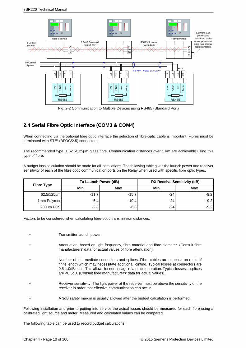
7SR220 Technical Manual
Chapter 4 - Page 10 of 100 © 2015 Siemens Protection Devices Limited
To Control System 14
161820
RS485 Screened twisted pair
Rear terminals
141618
141618
RS485 Screened twisted pair
Rear terminals
Ext Wire loop (terminating
resistance) added where permanent drive from master station available
+ve
RS485
GN
D
-ve
Ter
m.
14 16 18 20
+ve
RS485
GN
D
-ve
Ter
m.
14 16 18 20
+ve
RS485
GN
D
-ve
Ter
m.
14 16 18 20
RS 485 Twisted pair Cable
To Control System
Fig. 2-2 Communication to Multiple Devices using RS485 (Standard Port)
2.4 Serial Fibre Optic Interface (COM3 & COM4)
When connecting via the optional fibre optic interface the selection of fibre-optic cable is important. Fibres must beterminated with ST™ (BFOC/2.5) connectors.
The recommended type is 62.5/125µm glass fibre. Communication distances over 1 km are achievable using thistype of fibre.
A budget loss calculation should be made for all installations. The following table gives the launch power and receiversensitivity of each of the fibre optic communication ports on the Relay when used with specific fibre optic types.
Tx Launch Power (dB) RX Receive Sensitivity (dB)Fibre Type
Min Max Min Max
62.5/125µm -11.7 -15.7 -24 -9.2
1mm Polymer -6.4 -10.4 -24 -9.2
200µm PCS -2.8 -6.8 -24 -9.2
Factors to be considered when calculating fibre-optic transmission distances:
• Transmitter launch power.
• Attenuation, based on light frequency, fibre material and fibre diameter. (Consult fibremanufacturers' data for actual values of fibre attenuation).
• Number of intermediate connectors and splices. Fibre cables are supplied on reels offinite length which may necessitate additional jointing. Typical losses at connectors are0.5-1.0dB each. This allows for normal age related deterioration. Typical losses at splicesare <0.3dB. (Consult fibre manufacturers' data for actual values).
• Receiver sensitivity. The light power at the receiver must be above the sensitivity of thereceiver in order that effective communication can occur.
• A 3dB safety margin is usually allowed after the budget calculation is performed.
Following installation and prior to putting into service the actual losses should be measured for each fibre using acalibrated light source and meter. Measured and calculated values can be compared.
The following table can be used to record budget calculations:

Chapter 4 - 7SR220 · Data Communications Definitions
© 2015 Siemens Protection Devices Limited Chapter 4 - Page 11 of 100
A Launch power dB
B Fibre Type
C Loss (dB/km) dB/km
D Length km
E Total fibre loss (CxD) dB
F No. of Splices
G Loss at each splice dB
H Total loss at splices (FxG) dB
I No. of connectors
J Loss per connector dB
K Total loss at connectors (IxJ) dB
L Total losses (E+H+K) dB
M Receive power budget (A-L) dB
N Safety Margin dB
O Device Receive Sensitivity dB
The following settings, on the COMMUNICATIONS MENU, must be configured when using the fibre Optic Com3interface.
Setting Name Range/Options Default Setting Notes
COM3
Protocol
OFF
IEC60870-5-103
MODBUS-RTU
DNP3
IEC60870-5-103
The protocol usedto communicate onthe standard RS485connection.
COM3
Station
Address
0 - 254 for IEC60870-5-103
1 - 247 for Modbus RTU
0 - 65534 for DNP3.0
0
An address within therange of the relevantprotocol must begiven to identify therelay. Each relay in anetwork must have aunique address.
COM3
Baud Rate
75 110 150 300
600 1200 2400 4800
9600 19200 38400
57600 115200
19200
The baud rate seton all of the relaysconnected to thecontrol system mustbe the same as theone set on the masterdevice.
COM3
Parity
NONE
ODD
EVEN
EVEN
The parity set onall of the relaysconnected to thecontrol system mustbe the same and inaccordance with themaster device.
COM3
Line Idle
LIGHT ON
LIGHT OFFLIGHT OFF
Sets the fibre opticline idle state.
COM3
Data Echo#1
ON
OFFOFF
Set to ON whenrelays are connectedin a fibre-optic ringconfiguration.
COM3
Mode
Local
Local or Remote
Remote
RemoteRefer to Appendix1, page 99, forfurther explanation

7SR220 Technical Manual
Chapter 4 - Page 12 of 100 © 2015 Siemens Protection Devices Limited
The following settings, on the COMMUNICATIONS MENU, must be configured when using the fibre Optic Com4interface
Setting Name Range/Options Default Setting Notes
COM4
Protocol
OFF
IEC60870-5-103
MODBUS-RTU
DNP3
IEC60870-5-103
The protocol usedto communicate onthe standard RS485connection.
COM4
Station
Address
0 - 254 for IEC60870-5-103
1 - 247 for Modbus RTU
0 - 65534 for DNP3.0
0
An address within therange of the relevantprotocol must begiven to identify therelay. Each relay in anetwork must have aunique address.
COM4
Baud Rate
75 110 150 300
600 1200 2400 4800
9600 19200 38400
19200
The baud rate seton all of the relaysconnected to thecontrol system mustbe the same as theone set on the masterdevice.
COM4
Parity
NONE
ODD
EVEN
EVEN
The parity set onall of the relaysconnected to thecontrol system mustbe the same and inaccordance with themaster device.
COM4
Line Idle
LIGHT ON
LIGHT OFFLIGHT OFF
Sets the fibre opticline idle state.
COM4
Data Echo#1
ON
OFFOFF
Set to ON whenrelays are connectedin a fibre-optic ringconfiguration.
COM4
Mode
Local
Local or Remote
Remote
RemoteRefer to Appendix1, page 99, forfurther explanation
#1 In ring mode, echo = on, the whole fibre optic data comms link will be interrupted if the relay element is withdrawnfrom the case.

Chapter 4 - 7SR220 · Data Communications Definitions
© 2015 Siemens Protection Devices Limited Chapter 4 - Page 13 of 100
RS232 to Fibre Optic Converter
Tx
Rx Tx
Rx
62.5/125µm fibre optic with ST connectors
Tx
Rx
Tx
Rx
Computer or Control System
USB or 9 pin maleD connector
RS232 straightthrough cable
25 pin male D connector
Fig. 2-3 Communication to Multiple Devices using Fibre-optic Ring Network
Computer or Control System
7SG24 Sigma 1
Tx
Rx Tx
Rx
62.5/125µm fibre optic with ST connectors
Tx
Rx
Tx
Rx
Tx
Rx
Tx
Rx
Tx
Rx
Tx
RxMaster
To Control System
USB or 9 pin maleD connector
RS232 straightthrough cable
25 pin male D connector
Fig. 2-4 Communication to Multiple Devices from Control System and Laptop using Fibre-optic Star Network
2.5 Optional Rear RS485 (COM3)
The following settings, on the COMMUNICATIONS MENU, must be configured when using the electrical 2-wire RS485Com3 interface.

7SR220 Technical Manual
Chapter 4 - Page 14 of 100 © 2015 Siemens Protection Devices Limited
Setting Name Range/Options Default Setting Notes
COM3
Protocol
OFF
IEC60870-5-103
MODBUS-RTU
DNP3
IEC60870-5-103
The protocol usedto communicate onthe standard RS485connection.
COM3
Station
Address
0 - 254 for IEC60870-5-103
1 - 247 for Modbus RTU
0 - 65534 for DNP3.0
0
An address within therange of the relevantprotocol must begiven to identify therelay. Each relay in anetwork must have aunique address.
COM3
Baud Rate
75 110 150 300
600 1200 2400 4800
9600 19200 38400
57600 115200
19200
The baud rate seton all of the relaysconnected to thecontrol system mustbe the same as theone set on the masterdevice.
COM3
Parity
NONE
ODD
EVEN
EVEN
The parity set onall of the relaysconnected to thecontrol system mustbe the same and inaccordance with themaster device.
COM3
Line Idle
LIGHT ON
LIGHT OFFLIGHT OFF LIGHT OFF
Not applicable forRS 485 or RS 232option, set to OFF.
COM3
Data Echo#1
ON
OFFOFF OFF
Not applicable forRS 485 or RS 232option, set to OFF.
COM3
Mode
Local
Local or Remote
Remote
RemoteRefer to Appendix1, page 99, forfurther explanation
COMMS MODULE
IRIG-B
COM3
GND
TERM
B
A
Laptop computerRS232 straight through cable
USB or 9 pin male D connector
RS485 Screened twisted pair
7SR24
Fig. 2-5 Additional (Optional) Rear RS485 + IRIG-B Connection to a PC
2.6 Optional Rear RS232 (COM3)
The following settings, on the COMMUNICATIONS MENU, must be configured when using the electrical RS232Com3 interface.

Chapter 4 - 7SR220 · Data Communications Definitions
© 2015 Siemens Protection Devices Limited Chapter 4 - Page 15 of 100
Setting Name Range/Options Default Setting Notes
COM3
Protocol
OFF
IEC60870-5-103
MODBUS-RTU
DNP3
IEC60870-5-103
The protocol usedto communicate onthe standard RS485connection.
COM3
Station
Address
0 - 254 for IEC60870-5-103
1 - 247 for Modbus RTU
0 - 65534 for DNP3.0
0
An address within therange of the relevantprotocol must begiven to identify therelay. Each relay in anetwork must have aunique address.
COM3
Baud Rate
75 110 150 300
600 1200 2400 4800
9600 19200 38400
57600 115200
19200
The baud rate seton all of the relaysconnected to thecontrol system mustbe the same as theone set on the masterdevice.
COM3
Parity
NONE
ODD
EVEN
EVEN
The parity set onall of the relaysconnected to thecontrol system mustbe the same and inaccordance with themaster device.
COM3
Line Idle
LIGHT ON
LIGHT OFFLIGHT OFF LIGHT OFF
Not applicable forRS 485 or RS 232option, set to OFF.
COM3
Data Echo#1
ON
OFFOFF OFF
Not applicable forRS 485 or RS 232option, set to OFF.
COM3
Mode
Local
Local or Remote
Remote
RemoteRefer to Appendix1, page 99, forfurther explanation
USB or 9 pin male D connector
RS232 cross-over cable or RS232 to USB converter cableLaptop computer
COMMS MODULE
IRIG-B
COM3
7SR24
Fig. 2-6 Additional (Optional) Rear RS232 + IRIG-B Connection to a PC
Pin Relay Function
1 Not Connected
2 Receive Data (RXD)
3 Transmit Data (TXD)

7SR220 Technical Manual
Chapter 4 - Page 16 of 100 © 2015 Siemens Protection Devices Limited
Pin Relay Function
4 Output Supply +5V 50mA
5 Signal Ground (GND)
6 Output Supply +5V 50mA
7 Linked to 8 (volts free)
8 Linked to 7 (volts free)
9 Output Supply +5V 50mA
Fig. 2-7 RS232 Data Comms Pin Connections
2.7 Optional Rear EN100 Ethernet Module (COM3)
The optional ethernet interface is primarily provided for support of IEC 61850 Protocol. Support for IEC 60870-5-103is also provided over this interface to allow connection with Reydisp Evolution and Reydisp Manager Software forinterrogation, editing and download of relay settings and other data. Ordering options are available with two RJ45electrical connectors or with two duplex LC fibre optic connectors.
Setting Name Range/Options Default Setting Notes
LAN
Protocol
OFF
IEC60870-5-103IEC60870-5-103
Sets the protocolused to communicateon the LAN port.
If this setting is set to off, access to relay data using Reydisp Evolution and Reydisp Manager Software via theEthernet interface is not available.
Connections to the optional EN100 Ethernet module are made on the rear underside of the relay.
Connections are made to either RJ45 sockets (electrical) or Duplex LC (fibre optic) connectors. Fibre cables shouldbe 62.5/125µm (or 50/125µm) multimode with LC connectors.
The two types of EN100 module work slightly differently. The optical version contains an Ethernet switch to controlthe two channels. The switch will manage data from either channel as an Ethernet switch would in a network. Theelectrical version connects through one channel until it detects a break in the data traffic. After a delay it will swap tothe other channel to try and re-establish communication. Either method can be thought of as providing for redundancy.
While a 61850 session is established, an operator can simultaneously connect to the device via Reydisp Evolutionor a web browser through the EN100 module.
Configuration of 61850 communication is via the Reydisp Manager software package.

Chapter 4 - 7SR220 · Data Communications Definitions
© 2015 Siemens Protection Devices Limited Chapter 4 - Page 17 of 100
LED yellow
LED green
LED yellow
LED green
Ch 1 Ch 2
Ethernet – EN100-E
EN100 Module – RJ45 Interface
Ethernet – EN100-O
Ch 1 Ch 2
EN100 Module – Duplex-LC Interface
Green LED (Physical Link)Off – No linkOn – Link present
Yellow LED (Activity)Off – No trafficOn/flashing - Traffic
Fig. 2-8 EN100 Ethernet Module

7SR220 Technical Manual
Chapter 4 - Page 18 of 100 © 2015 Siemens Protection Devices Limited

Chapter 4 - 7SR220 · Data Communications Definitions
© 2015 Siemens Protection Devices Limited Chapter 4 - Page 19 of 100
3. IEC 60870-5-103 Definitions3.1 Introduction
This section describes the IEC 60870-5-103 protocol implementation in the relays. This protocol is used for thecommunication with Reydisp software and can also be used for communication with a suitable control system.The control system or local PC acts as the master in the system with the relay operating as a slave respondingto the master's commands. The implementation provides event information, time synchronising, commands andmeasurands and also supports the transfer of disturbance records.
This protocol can be set to use any or all of the relays hardware interfaces (USB, Fibre Optic, RS232, RS485 andEthernet) and is the standard protocol used by the USB port. The relay can communicate simultaneously on all portsregardless of protocol used.
The Station Address of the port being used must be set to a suitable address within the range 0 - 254 to enablecommunication. This can be set by the Communications Menu : COM n-xxxxx Station Address setting.

7SR220 Technical Manual
Chapter 4 - Page 20 of 100 © 2015 Siemens Protection Devices Limited
3.2 Cause of Transmission
The cause of transmission (COT) column of the “Information Number and Function” table lists possible causes oftransmission for these frames. The following abbreviations are used:
Abbreviation Description
SE spontaneous event
T test mode
GI general interrogation
Loc local operation
Rem remote operation
Ack command acknowledge
Nak Negative command acknowledge
Note: Events listing a GI cause of transmission can be raised and cleared; other events are raised only.

Chapter 4 - 7SR220 · Data Communications Definitions
© 2015 Siemens Protection Devices Limited Chapter 4 - Page 21 of 100
3.3 Application Service Data Unit (ASDU) Type
The Application Service Data Unit (ASDU) column of the “Information Number and Function” table lists the possibleASDUs returned for a point.
ASDU # Description
1 Time tagged message (monitor direction)
2 Time tagged message (relative time) (monitor direction)
3.1 Measurands I
4 Time-tagged measurands with relative time
5 Identification message
6 Time synchronisation
7 General Interrogation Initialization
9 Measurands II
20 General command

7SR220 Technical Manual
Chapter 4 - Page 22 of 100 © 2015 Siemens Protection Devices Limited
3.4 Point List
The following sub-sections contain tables listing the data points available via the IEC60870-5-103 protocol.
The information shown below is the default configuration. This can be modified using the CommunicationsConfiguration Editor tool, refer section 9 for details.
3.4.1 Event Function (FUN) & Information (INF) Numbers
The following Event EVT and INF numbers apply to this device.
FW# FUN INF Description ASDU COT
1 SE, GI60 4 Remote Mode
20 Ack, Nak
1 SE, GI60 5 Out Of Service Mode
20 Ack, Nak
1 SE, GI60 6 Local Mode
20 Ack, Nak
1 SE, GI60 7 Local & Remote
20 Ack, Nak
60 12 Control Received 1 SE
60 13 Command Received 1 SE
60 128 Cold Start 1 SE
60 129 Warm Start 1 SE
60 130 Re-Start 1 SE
R7b-7c 60 131 Expected Restart 1 SE, GI
R7b-7c 60 132 Unexpected Restart 1 SE, GI
1 SER7b-7c 60 133 Reset Start Count
20 Ack, Nak
60 135 Trigger Storage 1 SE
60 136 Clear Waveform Records 1 SE
60 137 Clear Fault Records 1 SE
60 138 Clear Event Records 1 SE
1 SE60 140 Demand metering reset
20 Ack, Nak
60 170 General Alarm 1 1 SE, GI
60 171 General Alarm 2 1 SE, GI
60 172 General Alarm 3 1 SE, GI
60 173 General Alarm 4 1 SE, GI
60 174 General Alarm 5 1 SE, GI
60 175 General Alarm 6 1 SE, GI
60 176 General Alarm 7 1 SE, GI
60 177 General Alarm 8 1 SE, GI
60 178 General Alarm 9 1 SE, GI
60 179 General Alarm 10 1 SE, GI
60 180 General Alarm 11 1 SE, GI
60 181 General Alarm 12 1 SE, GI
60 182 Quick Logic E1 1 SE, GI
60 183 Quick Logic E2 1 SE, GI
60 184 Quick Logic E3 1 SE, GI

Chapter 4 - 7SR220 · Data Communications Definitions
© 2015 Siemens Protection Devices Limited Chapter 4 - Page 23 of 100
FW# FUN INF Description ASDU COT
60 185 Quick Logic E4 1 SE, GI
60 186 Quick Logic E5 1 SE, GI
60 187 Quick Logic E6 1 SE, GI
60 188 Quick Logic E7 1 SE, GI
60 189 Quick Logic E8 1 SE, GI
60 190 Quick Logic E9 1 SE, GI
60 191 Quick Logic E10 1 SE, GI
60 192 Quick Logic E11 1 SE, GI
60 193 Quick Logic E12 1 SE, GI
60 194 Quick Logic E13 1 SE, GI
60 195 Quick Logic E14 1 SE, GI
60 196 Quick Logic E15 1 SE, GI
60 197 Quick Logic E16 1 SE, GI
60 214 Function Key 1 1 SE
60 215 Function Key 2 1 SE
60 216 Function Key 3 1 SE
60 217 Function Key 4 1 SE
60 218 Function Key 5 1 SE
60 219 Function Key 6 1 SE
R7b-7c 61 1 General Alarm 13 1 SE, GI
R7b-7c 61 2 General Alarm 14 1 SE, GI
R7b-7c 61 3 General Alarm 15 1 SE, GI
R7b-7c 61 4 General Alarm 16 1 SE, GI
R7b-7c 61 5 General Alarm 17 1 SE, GI
R7b-7c 61 6 General Alarm 18 1 SE, GI
R7b-7c 61 7 General Alarm 19 1 SE, GI
R7b-7c 61 8 General Alarm 20 1 SE, GI
70 5 Binary Input 5 1 SE, GI
70 6 Binary Input 6 1 SE, GI
70 7 Binary Input 7 1 SE, GI
70 8 Binary Input 8 1 SE, GI
70 9 Binary Input 9 1 SE, GI
70 10 Binary Input 10 1 SE, GI
70 11 Binary Input 11 1 SE, GI
70 12 Binary Input 12 1 SE, GI
70 13 Binary Input 13 1 SE, GI
R7b-7c 75 1 Virtual Input 1 1 SE, GI
R7b-7c 75 2 Virtual Input 2 1 SE, GI
R7b-7c 75 3 Virtual Input 3 1 SE, GI
R7b-7c 75 4 Virtual Input 4 1 SE, GI
R7b-7c 75 5 Virtual Input 5 1 SE, GI
R7b-7c 75 6 Virtual Input 6 1 SE, GI
R7b-7c 75 7 Virtual Input 7 1 SE, GI
R7b-7c 75 8 Virtual Input 8 1 SE, GI

7SR220 Technical Manual
Chapter 4 - Page 24 of 100 © 2015 Siemens Protection Devices Limited
FW# FUN INF Description ASDU COT
R7b-7c 75 9 Virtual Input 9 1 SE, GI
R7b-7c 75 10 Virtual Input 10 1 SE, GI
R7b-7c 75 11 Virtual Input 11 1 SE, GI
R7b-7c 75 12 Virtual Input 12 1 SE, GI
R7b-7c 75 13 Virtual Input 13 1 SE, GI
R7b-7c 75 14 Virtual Input 14 1 SE, GI
R7b-7c 75 15 Virtual Input 15 1 SE, GI
R7b-7c 75 16 Virtual Input 16 1 SE, GI
1 SE, GI80 1 Binary Output 1
20 Ack, Nak
1 SE, GI80 2 Binary Output 2
20 Ack, Nak
1 SE, GI80 3 Binary Output 3
20 Ack, Nak
1 SE, GI80 4 Binary Output 4
20 Ack, Nak
1 SE, GI80 5 Binary Output 5
20 Ack, Nak
1 SE, GI80 6 Binary Output 6
20 Ack, Nak
1 SE, GI80 7 Binary Output 7
20 Ack, Nak
1 SE, GI80 8 Binary Output 8
20 Ack, Nak
1 SE, GI80 9 Binary Output 9
20 Ack, Nak
1 SE, GI80 10 Binary Output 10
20 Ack, Nak
1 SE, GI80 11 Binary Output 11
20 Ack, Nak
1 SE, GI80 12 Binary Output 12
20 Ack, Nak
1 SE, GI80 13 Binary Output 13
20 Ack, Nak
1 SE, GI80 14 Binary Output 14
20 Ack, Nak
R7b-7c 90 1 LED 1 1 SE, GI
R7b-7c 90 2 LED 2 1 SE, GI
R7b-7c 90 3 LED 3 1 SE, GI
R7b-7c 90 4 LED 4 1 SE, GI
R7b-7c 90 5 LED 5 1 SE, GI
R7b-7c 90 6 LED 6 1 SE, GI
R7b-7c 90 7 LED 7 1 SE, GI
R7b-7c 90 8 LED 8 1 SE, GI
R7b-7c 90 9 LED 9 1 SE, GI

Chapter 4 - 7SR220 · Data Communications Definitions
© 2015 Siemens Protection Devices Limited Chapter 4 - Page 25 of 100
FW# FUN INF Description ASDU COT
R7b-7c 90 10 LED 10 1 SE, GI
R7b-7c 90 11 LED 11 1 SE, GI
R7b-7c 90 12 LED 12 1 SE, GI
R7b-7c 90 13 LED 13 1 SE, GI
R7b-7c 90 14 LED 14 1 SE, GI
R7b-7c 90 15 LED 15 1 SE, GI
R7b-7c 90 16 LED 16 1 SE, GI
R7b-7c 91 1 LED PU 1 1 SE, GI
R7b-7c 91 2 LED PU 2 1 SE, GI
R7b-7c 91 3 LED PU 3 1 SE, GI
R7b-7c 91 4 LED PU 4 1 SE, GI
R7b-7c 91 5 LED PU 5 1 SE, GI
R7b-7c 91 6 LED PU 6 1 SE, GI
R7b-7c 91 7 LED PU 7 1 SE, GI
R7b-7c 91 8 LED PU 8 1 SE, GI
R7b-7c 91 9 LED PU 9 1 SE, GI
R7b-7c 91 10 LED PU 10 1 SE, GI
R7b-7c 91 11 LED PU 11 1 SE, GI
R7b-7c 91 12 LED PU 12 1 SE, GI
R7b-7c 91 13 LED PU 13 1 SE, GI
R7b-7c 91 14 LED PU 14 1 SE, GI
R7b-7c 91 15 LED PU 15 1 SE, GI
R7b-7c 91 16 LED PU 16 1 SE, GI
160 2 Reset FCB 5 SE
160 3 Reset CU 5 SE
160 4 Start/Restart 5 SE
160 5 Power On 1 SE, GI
1 SE, GI160 16 Auto-reclose active
20 Ack, Nak
1 SE160 19 LED Reset
20 Ack, Nak
160 22 Settings changed 1 SE
1 SE, GI160 23 Setting G1 selected
20 Ack, Nak
1 SE, GI160 24 Setting G2 selected
20 Ack, Nak
1 SE, GI160 25 Setting G3 selected
20 Ack, Nak
1 SE, GI160 26 Setting G4 selected
20 Ack, Nak
160 27 Binary Input 1 1 SE, GI
160 28 Binary Input 2 1 SE, GI
160 29 Binary Input 3 1 SE, GI

7SR220 Technical Manual
Chapter 4 - Page 26 of 100 © 2015 Siemens Protection Devices Limited
FW# FUN INF Description ASDU COT
160 30 Binary Input 4 1 SE, GI
160 36 Trip Circuit Fail 1 SE, GI
160 38 VT Fuse Failure 1 SE, GI
160 51 Earth Fault Forward/Line 2 SE, GI
160 52 Earth Fault Reverse/Busbar 2 SE, GI
160 64 Start/Pick-up L1 2 SE, GI
160 65 Start/Pick-up L2 2 SE, GI
160 66 Start/Pick-up L3 2 SE, GI
160 67 Start/Pick-up N 2 SE, GI
160 68 General Trip 2 SE
160 69 Trip L1 2 SE
160 70 Trip L2 2 SE
160 71 Trip L3 2 SE
R7e-7c 160 73 Fault Impedance 1 SE
160 74 Fault Forward/Line 2 SE, GI
160 75 Fault Reverse/Busbar 2 SE, GI
160 84 General Start/Pick-up 2 SE, GI
160 85 Breaker Failure 2 SE
160 90 Trip I> 2 SE
160 91 Trip I>> 2 SE
160 92 Trip In> 2 SE
160 93 Trip In>> 2 SE
160 128 CB on by auto reclose 1 SE
183 10 51-1 2 SE, GI
183 11 50-1 2 SE, GI
183 12 51N-1 2 SE, GI
183 13 50N-1 2 SE, GI
183 14 51G-1 2 SE, GI
183 15 50G-1 2 SE, GI
183 16 51-2 2 SE, GI
183 17 50-2 2 SE, GI
183 18 51N-2 2 SE, GI
183 19 50N-2 2 SE, GI
183 20 51G-2 2 SE, GI
183 21 50G-2 2 SE, GI
183 22 51-3 2 SE, GI
183 23 50-3 2 SE, GI
183 24 51N-3 2 SE, GI
183 25 50N-3 2 SE, GI
183 26 51G-3 2 SE, GI
183 27 50G-3 2 SE, GI
183 28 51-4 2 SE, GI
183 29 50-4 2 SE, GI
183 30 51N-4 2 SE, GI
183 31 50N-4 2 SE, GI
183 32 51G-4 2 SE, GI
183 33 50G-4 2 SE, GI
183 34 50BF Stage 2 2 SE, GI

Chapter 4 - 7SR220 · Data Communications Definitions
© 2015 Siemens Protection Devices Limited Chapter 4 - Page 27 of 100
FW# FUN INF Description ASDU COT
183 35 49-Alarm 2 SE, GI
183 36 49-Trip 2 SE, GI
183 40 60 CTS 2 SE, GI
183 41 51SEF-1 2 SE, GI
183 42 50SEF-1 2 SE, GI
183 43 51SEF-2 2 SE, GI
183 44 50SEF-2 2 SE, GI
183 45 51SEF-3 2 SE, GI
183 46 50SEF-3 2 SE, GI
183 47 51SEF-4 2 SE, GI
183 48 50SEF-4 2 SE, GI
2 SE, GI183 49 SEF Out
20 Ack, Nak
183 50 46IT 2 SE, GI
183 51 46DT 2 SE, GI
183 52 64H 2 SE, GI
2 SE, GI183 53 E/F Out
20 Ack, Nak
R7b-7c 183 56 50BF Stage 1 2 SE, GI
183 60 47-1 2 SE, GI
183 61 47-2 2 SE, GI
183 62 37-1 2 SE, GI
183 63 37-2 2 SE, GI
183 64 37G-1 2 SE, GI
183 65 37G-2 2 SE, GI
183 66 37SEF-1 2 SE, GI
183 67 37SEF-2 2 SE, GI
183 70 46BC 2 SE, GI
183 81 27/59-1 2 SE, GI
183 82 27/59-2 2 SE, GI
183 83 27/59-3 2 SE, GI
183 84 27/59-4 2 SE, GI
183 85 59NIT 2 SE, GI
183 86 59NDT 2 SE, GI
183 87 Vx27/59 2 SE, GI
183 90 81-1 2 SE, GI
183 91 81-2 2 SE, GI
183 92 81-3 2 SE, GI
183 93 81-4 2 SE, GI
183 94 81-5 2 SE, GI
183 95 81-6 2 SE, GI
183 96 81HBL2 1 SE, GI
R7b-7c 183 100 CB Alarm 1 SE, GI
183 101 Trip Circuit Fail 1 2 SE, GI
183 102 Trip Circuit Fail 2 2 SE, GI
183 103 Trip Circuit Fail 3 2 SE, GI
183 110 Setting G5 selected 1 SE, GI

7SR220 Technical Manual
Chapter 4 - Page 28 of 100 © 2015 Siemens Protection Devices Limited
FW# FUN INF Description ASDU COT
20 Ack, Nak
1 SE, GI183 111 Setting G6 selected
20 Ack, Nak
1 SE, GI183 112 Setting G7 selected
20 Ack, Nak
1 SE, GI183 113 Setting G8 selected
20 Ack, Nak
183 114 Close CB Failed 1 SE, GI
183 115 Open CB Failed 1 SE, GI
183 116 Reclaim 1 SE, GI
183 117 Lockout 1 SE, GI
183 119 Successful DAR Close 1 SE
183 120 Successful Man Close 1 SE
1 SE, GI183 121 HotLine Working
20 Ack, Nak
1 SE, GI183 122 Inst Protection Out
20 Ack, Nak
183 123 CB Total Trip Count 1 SE, GI
183 124 CB Delta Trip Count 1 SE, GI
183 125 CB Count To AR Block 1 SE, GI
1 SE183 126 Reset CB Total Trip Count
20 Ack, Nak
1 SE183 127 Reset CB Delta Trip Count
20 Ack, Nak
1 SE183 128 Reset CB Count To AR Block
20 Ack, Nak
183 129 I^2t CB Wear 1 SE, GI
1 SE183 130 Reset I^2t CB Wear
20 Ack, Nak
183 131 79 AR In progress 1 SE, GI
183 132 CB Frequent Ops Count 1 SE, GI
1 SE183 133 Reset CB Frequent Ops Count
20 Ack, Nak
R7e-7c 183 136 CB On By Manual Close 1 SE
R7b-7c 183 137 CB on by auto reclose 1 SE, GI
183 140 Cold Load Active 1 SE, GI
183 141 P/F Inst Protection Inhibited 1 SE, GI
183 142 E/F Inst Protection Inhibited 1 SE, GI
183 143 SEF Inst Protection Inhibited 1 SE, GI
183 144 Ext Inst Protection Inhibited 1 SE, GI
183 163 Trip Time Alarm 1 SE
183 164 Close Circuit Fail 1 2 SE, GI
183 165 Close Circuit Fail 2 2 SE, GI
183 166 Close Circuit Fail 3 2 SE, GI
183 167 Close Circuit Fail 2 SE, GI
R7e-7c 183 168 Distance To Fault 1 SE
R7e-7c 183 169 Distance To Fault Percent 1 SE

Chapter 4 - 7SR220 · Data Communications Definitions
© 2015 Siemens Protection Devices Limited Chapter 4 - Page 29 of 100
FW# FUN INF Description ASDU COT
R7e-7c 183 170 Fault Reactance 1 SE
183 171 60 CTS-I 2 SE, GI
183 172 Act Energy Exp 4 SE
183 173 Act Energy Imp 4 SE
183 174 React Energy Exp 4 SE
183 175 React Energy Imp 4 SE
1 SE183 176 Reset Energy Meters
20 Ack, Nak
183 177 Active Exp Meter Reset 1 SE
183 178 Active Imp Meter Reset 1 SE
183 179 Reactive Exp Meter Reset 1 SE
183 180 Reactive Imp Meter Reset 1 SE
183 181 CB Total Trip Count 4 SE
183 182 CB Delta Trip Count 4 SE
183 183 CB Count To AR Block 4 SE
183 184 CB Freq Ops Count 4 SE
R7e-7c 183 198 25 Check Sync 1 SE, GI
R7e-7c 183 199 25 System Sync 1 SE, GI
R7e-7c 183 200 25 Close On Zero 1 SE, GI
R7e-7c 183 201 25 System Split 1 SE, GI
R7e-7c 183 202 25 Live Line 1 SE, GI
R7e-7c 183 203 25 Live Bus 1 SE, GI
R7e-7c 183 204 25 Line U/V 1 SE, GI
R7e-7c 183 205 25 Bus U/V 1 SE, GI
R7e-7c 183 206 25 Voltage Dif > 1 SE, GI
R7e-7c 183 207 25 CS Slip Freq > 1 SE, GI
R7e-7c 183 208 25 SS Slip Freq > 1 SE, GI
R7e-7c 183 209 25 COZ Slip Freq > 1 SE, GI
R7e-7c 183 210 25 In Sync 1 SE, GI
R7e-7c 183 211 25 CS In Progress 1 SE, GI
R7e-7c 183 212 25 SS In Progress 1 SE, GI
R7e-7c 183 213 25 COZ In Progress 1 SE, GI
R7e-7c 183 214 25 System Split LO 1 SE, GI
R7e-7c 183 215 60VTF-Bus 1 SE, GI
1 SE, GIR7e-7c 183 217 Man Override Sync
20 Ack, Nak
1 SE, GIR7e-7c 183 218 79 Override Sync
20 Ack, Nak
R7e-7c 183 219 Dead Line Close 1 SE, GI
R7e-7c 183 220 Dead Bus Close 1 SE, GI
R7b-7c 183 222 37-PhA 2 SE, GI
R7b-7c 183 223 37-PhB 2 SE, GI
R7b-7c 183 224 37-PhC 2 SE, GI

7SR220 Technical Manual
Chapter 4 - Page 30 of 100 © 2015 Siemens Protection Devices Limited
FW# FUN INF Description ASDU COT
R7b-7c 183 231 50BF-PhA 2 SE, GI
R7b-7c 183 232 50BF-PhB 2 SE, GI
R7b-7c 183 233 50BF-PhC 2 SE, GI
R7b-7c 183 234 50BF-EF 2 SE, GI
R7b-7c 183 235 79 Last Trip Lockout 2 SE, GI
R7f-7d 183 237 CB DBI 1 SE, GI
R7f-7d 183 238 CB Travelling 1 SE, GI
R7e-7c 183 239 In Fault Current 4 SE
R7e-7c 183 240 Ia Fault Current 4 SE
R7e-7c 183 241 Ib Fault Current 4 SE
R7e-7c 183 242 Ic Fault Current 4 SE
R7e-7c 183 243 Ig Fault Current 4 SE
R7e-7c 183 244 Isef Fault Current 4 SE
R7e-7c 183 245 Va Fault Voltage 4 SE
R7e-7c 183 246 Vb Fault Voltage 4 SE
R7e-7c 183 247 Vc Fault Voltage 4 SE
183 249 60 CTS-I-PhA 2 SE, GI
R7b-7c 183 250 60 CTS-I-PhB 2 SE, GI
R7b-7c 183 251 60 CTS-I-PhC 2 SE, GI
R7b-7c 183 252 Trip PhA 2 SE, GI
R7b-7c 183 253 Trip PhB 2 SE, GI
R7b-7c 183 254 Trip PhC 2 SE, GI
R7b-7c 185 9 CB Phase A Trip Count 4 SE
R7b-7c 185 10 CB Phase B Trip Count 4 SE
R7b-7c 185 11 CB Phase C Trip Count 4 SE
R7b-7c 185 12 CB E/F Trip Count 4 SE
185 37 27/59 PhA 2 SE, GI
185 38 27/59 PhB 2 SE, GI
185 39 27/59 PhC 2 SE, GI
R7b-7c 185 43 General Trip 2 SE, GI
R7e-7c 185 171 User Output 1 1 SE, GI
R7e-7c 185 172 User Output 2 1 SE, GI
R7e-7c 185 173 User Output 3 1 SE, GI
R7e-7c 185 174 User Output 4 1 SE, GI
R7e-7c 185 175 User Output 5 1 SE, GI
R7e-7c 185 176 User Output 6 1 SE, GI
R7e-7c 185 177 User Output 7 1 SE, GI
R7e-7c 185 178 User Output 8 1 SE, GI
R7e-7c 185 179 User Output 9 1 SE, GI
R7e-7c 185 180 User Output 10 1 SE, GI
R7e-7c 185 181 User Output 11 1 SE, GI

Chapter 4 - 7SR220 · Data Communications Definitions
© 2015 Siemens Protection Devices Limited Chapter 4 - Page 31 of 100
FW# FUN INF Description ASDU COT
R7e-7c 185 182 User Output 12 1 SE, GI
R7e-7c 185 183 User Output 13 1 SE, GI
R7e-7c 185 184 User Output 14 1 SE, GI
R7e-7c 185 185 User Output 15 1 SE, GI
R7e-7c 185 186 User Output 16 1 SE, GI
R7e-7c 185 187 User Output 17 1 SE, GI
R7e-7c 185 188 User Output 18 1 SE, GI
R7e-7c 185 189 User Output 19 1 SE, GI
R7e-7c 185 190 User Output 20 1 SE, GI
R7e-7c 185 191 User Output 21 1 SE, GI
R7e-7c 185 192 User Output 22 1 SE, GI
R7e-7c 185 193 User Output 23 1 SE, GI
R7e-7c 185 194 User Output 24 1 SE, GI
R7e-7c 185 195 User Output 25 1 SE, GI
R7e-7c 185 196 User Output 26 1 SE, GI
R7e-7c 185 197 User Output 27 1 SE, GI
R7e-7c 185 198 User Output 28 1 SE, GI
R7e-7c 185 199 User Output 29 1 SE, GI
R7e-7c 185 200 User Output 30 1 SE, GI
R7e-7c 185 201 User Output 31 1 SE, GI
R7e-7c 185 202 User Output 32 1 SE, GI
R7f-7d 185 238 E/F In 2 SE, GI
R7f-7d 185 239 SEF In 2 SE, GI
R7f-7e 185 241 Start Count Alarm 1 SE, GI
R8a-7f 185 242 21LB-3P Fwd 1 SE, GI
R8a-7f 185 243 21LB-3P Rev 1 SE, GI
R8a-7f 185 244 21LB-1P Fwd 1 SE, GI
R8a-7f 185 245 21LB-1P Rev 1 SE, GI
R8a-7f 186 1 50AFD PhA 1 SE, GI
R8a-7f 186 2 50AFD PhB 1 SE, GI
R8a-7f 186 3 50AFD PhC 1 SE, GI
R8a-7f 186 4 50AFD 1 SE, GI
R8a-7f 186 5 AFD Zone 1 Flash 1 SE, GI
R8a-7f 186 6 AFD Zone 1 1 SE, GI
R8a-7f 186 7 AFD Zone 2 Flash 1 SE, GI
R8a-7f 186 8 AFD Zone 2 1 SE, GI
R8a-7f 186 9 AFD Zone 3 Flash 1 SE, GI
R8a-7f 186 10 AFD Zone 3 1 SE, GI
R8a-7f 186 11 AFD Zone 4 Flash 1 SE, GI
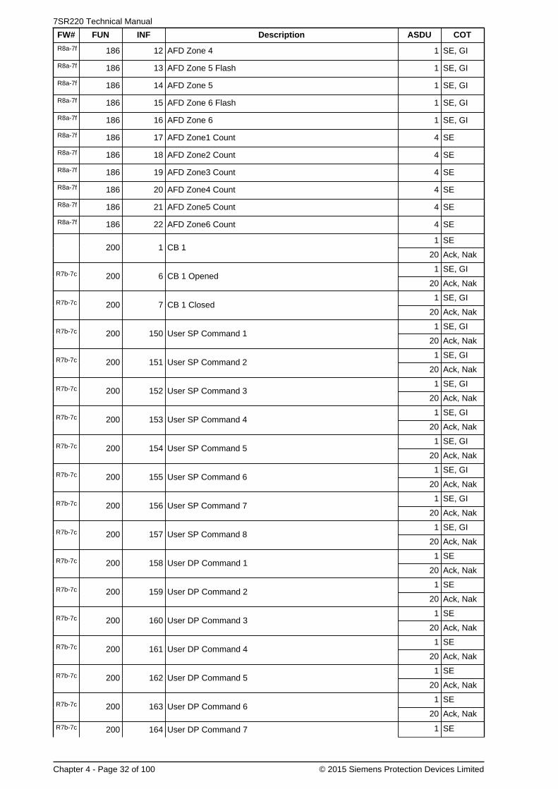
7SR220 Technical Manual
Chapter 4 - Page 32 of 100 © 2015 Siemens Protection Devices Limited
FW# FUN INF Description ASDU COT
R8a-7f 186 12 AFD Zone 4 1 SE, GI
R8a-7f 186 13 AFD Zone 5 Flash 1 SE, GI
R8a-7f 186 14 AFD Zone 5 1 SE, GI
R8a-7f 186 15 AFD Zone 6 Flash 1 SE, GI
R8a-7f 186 16 AFD Zone 6 1 SE, GI
R8a-7f 186 17 AFD Zone1 Count 4 SE
R8a-7f 186 18 AFD Zone2 Count 4 SE
R8a-7f 186 19 AFD Zone3 Count 4 SE
R8a-7f 186 20 AFD Zone4 Count 4 SE
R8a-7f 186 21 AFD Zone5 Count 4 SE
R8a-7f 186 22 AFD Zone6 Count 4 SE
1 SE200 1 CB 1
20 Ack, Nak
1 SE, GIR7b-7c 200 6 CB 1 Opened
20 Ack, Nak
1 SE, GIR7b-7c 200 7 CB 1 Closed
20 Ack, Nak
1 SE, GIR7b-7c 200 150 User SP Command 1
20 Ack, Nak
1 SE, GIR7b-7c 200 151 User SP Command 2
20 Ack, Nak
1 SE, GIR7b-7c 200 152 User SP Command 3
20 Ack, Nak
1 SE, GIR7b-7c 200 153 User SP Command 4
20 Ack, Nak
1 SE, GIR7b-7c 200 154 User SP Command 5
20 Ack, Nak
1 SE, GIR7b-7c 200 155 User SP Command 6
20 Ack, Nak
1 SE, GIR7b-7c 200 156 User SP Command 7
20 Ack, Nak
1 SE, GIR7b-7c 200 157 User SP Command 8
20 Ack, Nak
1 SER7b-7c 200 158 User DP Command 1
20 Ack, Nak
1 SER7b-7c 200 159 User DP Command 2
20 Ack, Nak
1 SER7b-7c 200 160 User DP Command 3
20 Ack, Nak
1 SER7b-7c 200 161 User DP Command 4
20 Ack, Nak
1 SER7b-7c 200 162 User DP Command 5
20 Ack, Nak
1 SER7b-7c 200 163 User DP Command 6
20 Ack, Nak
R7b-7c 200 164 User DP Command 7 1 SE

Chapter 4 - 7SR220 · Data Communications Definitions
© 2015 Siemens Protection Devices Limited Chapter 4 - Page 33 of 100
FW# FUN INF Description ASDU COT
20 Ack, Nak
1 SER7b-7c 200 165 User DP Command 8
20 Ack, Nak
1 SE200 200 CB 1 Trip & Reclose
20 Ack, Nak
1 SE200 201 CB 1 Trip & Lockout
20 Ack, Nak
200 255 Blocked By Interlocking 1 SE, GI
255 0 General Interrogation (GI) Initiation 7 Init. GI
255 0 General Interrogation (GI) End 8 End of GI
255 0 Time Synchronisation 6TimeSynch.
3.4.2 Measurands
The following Measurand EVT and INF numbers apply to this device.
FW# FUN INF Description ASDU COT
183 148
Measurand IL1,2,3, VL1,2,3, P, Q, F, VL1-2,L2-3,L3-1
---
IL1 (2.4x) (Window 1%)
IL2 (2.4x) (Window 1%)
IL3 (2.4x) (Window 1%)
VL1 (1.2x) (Window 1%)
VL2 (1.2x) (Window 1%)
VL3 (1.2x) (Window 1%)
P (2.4x) (Window 1%)
Q (2.4x) (Window 1%)
F (1.2x) (Window 0.1%)
VL1-2 (1.2x) (Window 1%)
VL2-3 (1.2x) (Window 1%)
VL3-1 (1.2x) (Window 1%)
9
Cyclic -Refreshrate 5secondsor valuechangegreaterthanWindow x%.
R7e-7c 183 216
Measurand Vx, Bus Freq, Phase Diff, Diff Volts and Slip Freq
---
Vx (1.2x) (Window 0%)
Bus Freq (1.2x) (Window 0%)
Phase Diff (1.2x) (Window 0%)
Diff Volts (1.2x) (Window 0%)
Slip Freq (1.2x) (Window 0%)
---
Note - Phase difference is stored as -1to +1 as a multiple of 180deg nominal
9
Cyclic -Refreshrate 5secondsor valuechangegreaterthanWindow x%.
3.4.3 Disturbance Recorder Actual Channel (ACC) Numbers
The following Disturbance Recorder channel numbers apply to this device.

7SR220 Technical Manual
Chapter 4 - Page 34 of 100 © 2015 Siemens Protection Devices Limited
FW# FUN ACC Description
182 1 V1
182 2 V2
182 3 V3
182 4 Vx
182 5 Ia
182 6 Ib
182 7 Ic
182 8 Ig1
182 9 Ig2

Chapter 4 - 7SR220 · Data Communications Definitions
© 2015 Siemens Protection Devices Limited Chapter 4 - Page 35 of 100
4. MODBUS Definitions4.1 Introduction
This section describes the MODBUS-RTU protocol implementation in the relays. This protocol is used forcommunication with a suitable control system.
This protocol can be set to use any or all of the relays hardware interfaces (USB, Fibre Optic, RS232 and RS485).The relay can communicate simultaneously on all ports regardless of protocol used.
The Station Address of the port being used must be set to a suitable address within the range 1 - 247 to enablecommunication. This can be set by the Communications Menu : COM n-xxxxx Station Address setting.
Communication via MODBUS over Ethernet requires external devices. Please refer to the documents TCPIPCatalogue Sheet and TCPIP Interface Technical Guidance Notes for more information.
Definitions with shaded area are not available on all relay models.
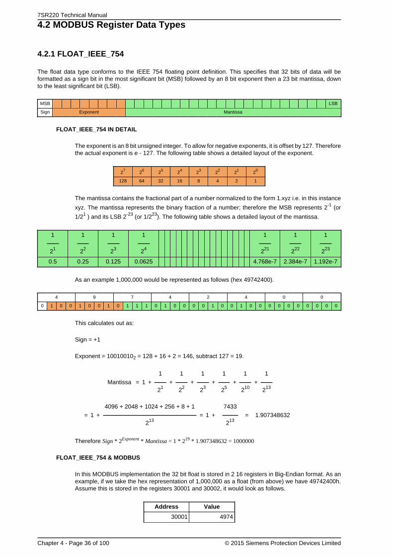
7SR220 Technical Manual
Chapter 4 - Page 36 of 100 © 2015 Siemens Protection Devices Limited
4.2 MODBUS Register Data Types
4.2.1 FLOAT_IEEE_754
The float data type conforms to the IEEE 754 floating point definition. This specifies that 32 bits of data will beformatted as a sign bit in the most significant bit (MSB) followed by an 8 bit exponent then a 23 bit mantissa, downto the least significant bit (LSB).
MSB LSB
Sign Exponent Mantissa
FLOAT_IEEE_754 IN DETAIL
The exponent is an 8 bit unsigned integer. To allow for negative exponents, it is offset by 127. Thereforethe actual exponent is e - 127. The following table shows a detailed layout of the exponent.
27 26 25 24 23 22 21 20
128 64 32 16 8 4 2 1
The mantissa contains the fractional part of a number normalized to the form 1.xyz i.e. in this instance
xyz. The mantissa represents the binary fraction of a number; therefore the MSB represents 2-1 (or
1/21 ) and its LSB 2-23 (or 1/223). The following table shows a detailed layout of the mantissa.
1
21
1
22
1
23
1
24
1
221
1
222
1
223
0.5 0.25 0.125 0.0625 4.768e-7 2.384e-7 1.192e-7
As an example 1,000,000 would be represented as follows (hex 49742400).
4 9 7 4 2 4 0 0
0 1 0 0 1 0 0 1 0 1 1 1 0 1 0 0 0 0 1 0 0 1 0 0 0 0 0 0 0 0 0 0
This calculates out as:
Sign = +1
Exponent = 100100102 = 128 + 16 + 2 = 146, subtract 127 = 19.
Mantissa = 1 +1
21+
1
22+
1
23+
1
25+
1
210+
1
213
= 1 +4096 + 2048 + 1024 + 256 + 8 + 1
213= 1 +
7433
213= 1.907348632
Therefore Sign * 2Exponent * Mantissa = 1 * 219 * 1.907348632 = 1000000
FLOAT_IEEE_754 & MODBUS
In this MODBUS implementation the 32 bit float is stored in 2 16 registers in Big-Endian format. As anexample, if we take the hex representation of 1,000,000 as a float (from above) we have 49742400h.Assume this is stored in the registers 30001 and 30002, it would look as follows.
Address Value
30001 4974

Chapter 4 - 7SR220 · Data Communications Definitions
© 2015 Siemens Protection Devices Limited Chapter 4 - Page 37 of 100
Address Value
30002 2400
On reception these two registers should be interpreted in the correct order as IEEE754 floating pointrepresentation.
4.2.2 FP_32BITS_3DP
The FP_32BITS_3DP is a 32 bit integer fixed point value, containing 3 decimal places of information. It is usedto send a real value to 3 decimal places as an integer. For example, if the value in a device is 123.456 it willbe sent as 123456. As it is an integer, negative numbers are sent as 2's complement.
FP_32BITS_3DP & MODBUS
In this MODBUS implementation the 32 bit value is stored in 2 16 registers in Big-Endian format. Asan example, if we take the hex representation of 123456, we have 1E240h. Assume this is stored inthe registers 30001 and 30002, it would look as follows:
Address Value
30001 1
30002 E240
On reception these two registers should be interpreted in the correct order as a 32 bit integer.
4.2.3 UINT32
The UINT32 is a signed 32 bit integer. As it is an integer, negative numbers are sent as 2's complement.
UINT32 & MODBUS
In this MODBUS implementation the 32 bit value is stored in 2 16 bit registers in Big-Endian format. Asan example, if we take the hex representation of -123456, in 2's complement, we have FFFE1DC0h.Assume this is stored in the registers 30001 and 30002, it would look as follows:
Address Value
30001 FFFE
30002 1DC0
On reception these two registers should be interpreted in the correct order as a 32 bit integer.
4.2.4 UINT16
The UINT16 is a signed 16 bit integer. As it is an integer, negative numbers are sent as 2's complement.
UINT16 & MODBUS
In this MODBUS implementation the 16 bit value is stored in a 16 bit register in Big-Endian format. Asan example, if we take the hex representation of 5678 we have 162Eh. Assume this is stored in theregister 30001, it would look as follows:
Address Value
30001 162E
On reception this register should be interpreted as a 16 bit integer.

7SR220 Technical Manual
Chapter 4 - Page 38 of 100 © 2015 Siemens Protection Devices Limited
Truncation
Calculations are performed as 32 bit. The 16 bit value is the lowest 16 bits of the 32 bit value. Therefore,when values overflow the returned value is the lowest 16 bits of the calculated value. For Example, if thevalue is 85400 = 14D98h, the value returned would be the lowest 16 bits = 4D98h which equals 19864.
4.2.5 EVENT
MODBUS does not define a method for extracting events; therefore a private method has been definedbased on that defined by IEC60870-5-103.
The EVENT register contains the earliest event record available. The event record is 8 registers (16bytes) of information, whose format is described below. When this record has been read it will bereplaced by the next available record. Event records must be read completely; therefore the quantityvalue must be set to 8 before reading. Failing to do this will result in an exception code 2. If no eventrecord is present the exception code 2 will be returned. The EVENT register should be polled regularlyby the master for events.
The EVENTCOUNT register can be checked periodically to determine how many events are stored.
The format of the event record is defined by the zero byte. It signifies the type of record which is usedto decode the event information. The zero byte can be one of the following.
Format
The format of the event record is defined by the zero byte. It signifies the type of record which is usedto decode the event information. The zero byte can be one of the following.
Type Description
1 Event
2 Event with Relative Time
4 Measurand Event with Relative Time
The following table describes the fields in the event record.
Key Description
FUN Function Type, as defined for IEC870-5-103.
INF Information Number, as defined for IEC870-5-103.
DPI Measurand Event with Relative Time, values 1 = OFF, 2 = ON.
ms L Time Stamp Milliseconds low byte.
ms H Time Stamp Milliseconds high byte.
Mi Time Stamp Minutes (MSB = invalid, time not set > 23 hours).
Ho Time Stamp Hours (MSB = Summer time flag).
RT L Relative Time low byte.
RT H Relative Time high byte.
F# L Fault Number low byte.
F# H Fault Number high byte.
Meas Measurand format R32.23, sent least significant byte first.
The following tables show the fields in the different event records as they are returned.
Byte 0 1 2 3 4 5 6 7 8 9 10 11 12 13 14 15
Content 1 0 FUN INF DPI 0 0 0 0 0 0 0 ms LmsH
Mi Ho
Event Type 1 Format.
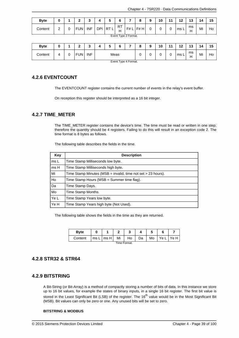
Chapter 4 - 7SR220 · Data Communications Definitions
© 2015 Siemens Protection Devices Limited Chapter 4 - Page 39 of 100
Byte 0 1 2 3 4 5 6 7 8 9 10 11 12 13 14 15
Content 2 0 FUN INF DPI RT LRTH
F# L F# H 0 0 0 ms LmsH
Mi Ho
Event Type 2 Format.
Byte 0 1 2 3 4 5 6 7 8 9 10 11 12 13 14 15
Content 4 0 FUN INF Meas 0 0 0 0 ms LmsH
Mi Ho
Event Type 4 Format.
4.2.6 EVENTCOUNT
The EVENTCOUNT register contains the current number of events in the relay's event buffer.
On reception this register should be interpreted as a 16 bit integer.
4.2.7 TIME_METER
The TIME_METER register contains the device's time. The time must be read or written in one step;therefore the quantity should be 4 registers. Failing to do this will result in an exception code 2. Thetime format is 8 bytes as follows.
The following table describes the fields in the time.
Key Description
ms L Time Stamp Milliseconds low byte.
ms H Time Stamp Milliseconds high byte.
Mi Time Stamp Minutes (MSB = invalid, time not set > 23 hours).
Ho Time Stamp Hours (MSB = Summer time flag).
Da Time Stamp Days.
Mo Time Stamp Months.
Ye L Time Stamp Years low byte.
Ye H Time Stamp Years high byte (Not Used).
The following table shows the fields in the time as they are returned.
Byte 0 1 2 3 4 5 6 7
Content ms L ms H Mi Ho Da Mo Ye L Ye HTime Format.
4.2.8 STR32 & STR64
4.2.9 BITSTRING
A Bit-String (or Bit-Array) is a method of compactly storing a number of bits of data. In this instance we storeup to 16 bit values, for example the states of binary inputs, in a single 16 bit register. The first bit value is
stored in the Least Significant Bit (LSB) of the register. The 16th value would be in the Most Significant Bit(MSB). Bit values can only be zero or one. Any unused bits will be set to zero.
BITSTRING & MODBUS

7SR220 Technical Manual
Chapter 4 - Page 40 of 100 © 2015 Siemens Protection Devices Limited
In this MODBUS implementation the 16 bit value is stored in a 16 bit register in Big-Endian format.As an example, assume bits 1, 3, 9 and 12 are set. The binary representation of this would be00001001000001012 giving a hex representation of 0905h. Assume this is stored in the register 30001,it would look as follows:
Address Value
30001 0905
On reception this register should be interpreted as a 16 bit integer.

Chapter 4 - 7SR220 · Data Communications Definitions
© 2015 Siemens Protection Devices Limited Chapter 4 - Page 41 of 100
4.3 Point List
The information shown below is the default configuration. This can be modified using the CommunicationsConfiguration Editor tool, refer section 9 for details.
4.3.1 Coils (Read Write Binary values)
FW# Address Name
00001 Binary Output 1
00002 Binary Output 2
00003 Binary Output 3
00004 Binary Output 4
00005 Binary Output 5
00006 Binary Output 6
00007 Binary Output 7
00008 Binary Output 8
00009 Binary Output 9
00010 Binary Output 10
00011 Binary Output 11
00012 Binary Output 12
00013 Binary Output 13
00014 Binary Output 14
00101 Setting G1 selected
00102 Setting G2 selected
00103 Setting G3 selected
00104 Setting G4 selected
00105 Setting G5 selected
00106 Setting G6 selected
00107 Setting G7 selected
00108 Setting G8 selected
00109 CB 1
00112 Auto-reclose active
00113 HotLine Working
00114 E/F Out
00115 SEF Out
00116 Inst Protection Out
00155 Remote Mode
00156 Out Of Service Mode
00157 Local Mode
00158 Local & Remote
R7e-7c 00159 Man Override Sync
R7e-7c 00160 79 Override Sync
R7b-7c 00165 Reset Start Count
R7b-7c 00180 CB 1 Opened
R7b-7c 00181 CB 1 Closed
R7b-7c 00200 User SP Command 1
R7b-7c 00201 User SP Command 2

7SR220 Technical Manual
Chapter 4 - Page 42 of 100 © 2015 Siemens Protection Devices Limited
FW# Address Name
R7b-7c 00202 User SP Command 3
R7b-7c 00203 User SP Command 4
R7b-7c 00204 User SP Command 5
R7b-7c 00205 User SP Command 6
R7b-7c 00206 User SP Command 7
R7b-7c 00207 User SP Command 8
R7b-7c 00208 User DP Command 1
R7b-7c 00209 User DP Command 2
R7b-7c 00210 User DP Command 3
R7b-7c 00211 User DP Command 4
R7b-7c 00212 User DP Command 5
R7b-7c 00213 User DP Command 6
R7b-7c 00214 User DP Command 7
R7b-7c 00215 User DP Command 8
4.3.2 Inputs (Read Only Binary values)
FW# Address Name
10001 Binary Input 1
10002 Binary Input 2
10003 Binary Input 3
10004 Binary Input 4
10005 Binary Input 5
10006 Binary Input 6
10007 Binary Input 7
10008 Binary Input 8
10009 Binary Input 9
10010 Binary Input 10
10011 Binary Input 11
10012 Binary Input 12
10013 Binary Input 13
10102 Remote Mode
10103 Out Of Service Mode
10104 Local Mode
10105 Local & Remote
R7b-7c 10110 General Trip
10111 Trip Circuit Fail
10112 Start/Pick-up L1
10113 Start/Pick-up L2
10114 Start/Pick-up L3
10115 General Start/Pick-up
10116 VT Fuse Failure
10117 Earth Fault Forward/Line
10118 Earth Fault Reverse/Busbar
10119 Start/Pick-up N

Chapter 4 - 7SR220 · Data Communications Definitions
© 2015 Siemens Protection Devices Limited Chapter 4 - Page 43 of 100
FW# Address Name
10120 Fault Forward/Line
10121 Fault Reverse/Busbar
10122 51-1
10123 50-1
10124 51N-1
10125 50N-1
10126 51G-1
10127 50G-1
10128 51-2
10129 50-2
10130 51N-2
10131 50N-2
10132 51G-2
10133 50G-2
10134 51-3
10135 50-3
10136 51N-3
10137 50N-3
10138 51G-3
10139 50G-3
10140 51-4
10141 50-4
10142 51N-4
10143 50N-4
10144 51G-4
10145 50G-4
10146 50BF Stage 2
10147 49-Alarm
10148 49-Trip
10149 60 CTS
10150 46IT
10151 46DT
10152 47-1
10153 47-2
10154 46BC
10155 27/59-1
10156 27/59-2
10157 27/59-3
10158 27/59-4
10159 59NIT
10160 59NDT
10161 81-1
10162 81-2
10163 81-3
10164 81-4
10165 81-5
10166 81-6
10167 64H

7SR220 Technical Manual
Chapter 4 - Page 44 of 100 © 2015 Siemens Protection Devices Limited
FW# Address Name
10168 37-1
10169 37-2
10170 Vx27/59
10171 Auto-reclose active
10172 CB on by auto reclose
10173 Reclaim
10174 Lockout
10175 HotLine Working
10176 Inst Protection Out
10177 CB Total Trip Count
10178 CB Delta Trip Count
10179 CB Count To AR Block
10180 I^2t CB Wear
10181 79 AR In progress
10182 Cold Load Active
10183 E/F Out
10184 P/F Inst Protection Inhibited
10185 E/F Inst Protection Inhibited
10186 SEF Inst Protection Inhibited
10187 Ext Inst Protection Inhibited
10202 51SEF-1
10203 50SEF-1
10204 51SEF-2
10205 50SEF-2
10206 51SEF-3
10207 50SEF-3
10208 51SEF-4
10209 50SEF-4
10210 SEF Out
10211 Trip Circuit Fail 1
10212 Trip Circuit Fail 2
10213 Trip Circuit Fail 3
10214 CB Total Trip Count
10215 CB Delta Trip Count
10216 CB Count To AR Block
10217 CB Frequent Ops Count
10218 I^2t CB Wear
10219 CB 1 Opened
10220 CB 1 Closed
10283 Close Circuit Fail 1
10284 Close Circuit Fail 2
10285 Close Circuit Fail 3
10286 Close Circuit Fail
10290 General Alarm 1
10291 General Alarm 2
10292 General Alarm 3
10293 General Alarm 4
10294 General Alarm 5
10295 General Alarm 6

Chapter 4 - 7SR220 · Data Communications Definitions
© 2015 Siemens Protection Devices Limited Chapter 4 - Page 45 of 100
FW# Address Name
10296 General Alarm 7
10297 General Alarm 8
10298 General Alarm 9
10299 General Alarm 10
10300 General Alarm 11
10301 General Alarm 12
10302 Quick Logic E1
10303 Quick Logic E2
10304 Quick Logic E3
10305 Quick Logic E4
10306 Quick Logic E5
10307 Quick Logic E6
10308 Quick Logic E7
10309 Quick Logic E8
10310 Quick Logic E9
10311 Quick Logic E10
10312 Quick Logic E11
10313 Quick Logic E12
10314 Quick Logic E13
10315 Quick Logic E14
10316 Quick Logic E15
10317 Quick Logic E16
10334 60 CTS-I
10335 81HBL2
10336 37G-1
10337 37G-2
10338 37SEF-1
10339 37SEF-2
R7e-7c 10352 25 System Split
R7e-7c 10353 25 Live Line
R7e-7c 10354 25 Live Bus
R7e-7c 10355 25 Line U/V
R7e-7c 10356 25 Bus U/V
R7e-7c 10357 25 Voltage Dif >
R7e-7c 10358 25 CS Slip Freq >
R7e-7c 10359 25 SS Slip Freq >
R7e-7c 10360 25 COZ Slip Freq >
R7e-7c 10361 25 In Sync
R7e-7c 10362 25 CS In Progress
R7e-7c 10363 25 SS In Progress
R7e-7c 10364 25 COZ In Progress
R7e-7c 10365 25 System Split LO
R7e-7c 10366 60VTF-Bus
R7b-7c 10367 50BF Stage 1
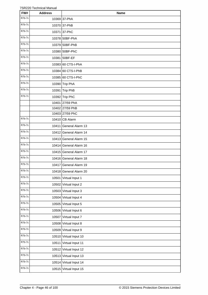
7SR220 Technical Manual
Chapter 4 - Page 46 of 100 © 2015 Siemens Protection Devices Limited
FW# Address Name
R7b-7c 10369 37-PhA
R7b-7c 10370 37-PhB
R7b-7c 10371 37-PhC
R7b-7c 10378 50BF-PhA
R7b-7c 10379 50BF-PhB
R7b-7c 10380 50BF-PhC
R7b-7c 10381 50BF-EF
R7b-7c 10383 60 CTS-I-PhA
R7b-7c 10384 60 CTS-I-PhB
R7b-7c 10385 60 CTS-I-PhC
R7b-7c 10390 Trip PhA
R7b-7c 10391 Trip PhB
R7b-7c 10392 Trip PhC
10401 27/59 PhA
10402 27/59 PhB
10403 27/59 PhC
R7b-7c 10410 CB Alarm
R7b-7c 10411 General Alarm 13
R7b-7c 10412 General Alarm 14
R7b-7c 10413 General Alarm 15
R7b-7c 10414 General Alarm 16
R7b-7c 10415 General Alarm 17
R7b-7c 10416 General Alarm 18
R7b-7c 10417 General Alarm 19
R7b-7c 10418 General Alarm 20
R7b-7c 10501 Virtual Input 1
R7b-7c 10502 Virtual Input 2
R7b-7c 10503 Virtual Input 3
R7b-7c 10504 Virtual Input 4
R7b-7c 10505 Virtual Input 5
R7b-7c 10506 Virtual Input 6
R7b-7c 10507 Virtual Input 7
R7b-7c 10508 Virtual Input 8
R7b-7c 10509 Virtual Input 9
R7b-7c 10510 Virtual Input 10
R7b-7c 10511 Virtual Input 11
R7b-7c 10512 Virtual Input 12
R7b-7c 10513 Virtual Input 13
R7b-7c 10514 Virtual Input 14
R7b-7c 10515 Virtual Input 15

Chapter 4 - 7SR220 · Data Communications Definitions
© 2015 Siemens Protection Devices Limited Chapter 4 - Page 47 of 100
FW# Address Name
R7b-7c 10516 Virtual Input 16
R7b-7c 10601 LED 1
R7b-7c 10602 LED 2
R7b-7c 10603 LED 3
R7b-7c 10604 LED 4
R7b-7c 10605 LED 5
R7b-7c 10606 LED 6
R7b-7c 10607 LED 7
R7b-7c 10608 LED 8
R7b-7c 10609 LED 9
R7b-7c 10610 LED 10
R7b-7c 10611 LED 11
R7b-7c 10612 LED 12
R7b-7c 10613 LED 13
R7b-7c 10614 LED 14
R7b-7c 10615 LED 15
R7b-7c 10616 LED 16
R7b-7c 10701 LED PU 1
R7b-7c 10702 LED PU 2
R7b-7c 10703 LED PU 3
R7b-7c 10704 LED PU 4
R7b-7c 10705 LED PU 5
R7b-7c 10706 LED PU 6
R7b-7c 10707 LED PU 7
R7b-7c 10708 LED PU 8
R7b-7c 10709 LED PU 9
R7b-7c 10710 LED PU 10
R7b-7c 10711 LED PU 11
R7b-7c 10712 LED PU 12
R7b-7c 10713 LED PU 13
R7b-7c 10714 LED PU 14
R7b-7c 10715 LED PU 15
R7b-7c 10716 LED PU 16
R7b-7c 10800 Cold Start
R7b-7c 10801 Warm Start
R7b-7c 10802 Re-Start
R7b-7c 10803 Power On
R7b-7c 10804 Expected Restart
R7b-7c 10805 Unexpected Restart

7SR220 Technical Manual
Chapter 4 - Page 48 of 100 © 2015 Siemens Protection Devices Limited
FW# Address Name
R7b-7c 10806 Reset Start Count
R7b-7c 10900 User SP Command 1
R7b-7c 10901 User SP Command 2
R7b-7c 10902 User SP Command 3
R7b-7c 10903 User SP Command 4
R7b-7c 10904 User SP Command 5
R7b-7c 10905 User SP Command 6
R7b-7c 10906 User SP Command 7
R7b-7c 10907 User SP Command 8
R7b-7c 10908 User DP Command 1
R7b-7c 10909 User DP Command 2
R7b-7c 10910 User DP Command 3
R7b-7c 10911 User DP Command 4
R7b-7c 10912 User DP Command 5
R7b-7c 10913 User DP Command 6
R7b-7c 10914 User DP Command 7
R7b-7c 10915 User DP Command 8
R7e-7c 11020 User Output 1
R7e-7c 11021 User Output 2
R7e-7c 11022 User Output 3
R7e-7c 11023 User Output 4
R7e-7c 11024 User Output 5
R7e-7c 11025 User Output 6
R7e-7c 11026 User Output 7
R7e-7c 11027 User Output 8
R7e-7c 11028 User Output 9
R7e-7c 11029 User Output 10
R7e-7c 11030 User Output 11
R7e-7c 11031 User Output 12
R7e-7c 11032 User Output 13
R7e-7c 11033 User Output 14
R7e-7c 11034 User Output 15
R7e-7c 11035 User Output 16
R7e-7c 11036 User Output 17
R7e-7c 11037 User Output 18
R7e-7c 11038 User Output 19
R7e-7c 11039 User Output 20
R7e-7c 11040 User Output 21
R7e-7c 11041 User Output 22
R7e-7c 11042 User Output 23

Chapter 4 - 7SR220 · Data Communications Definitions
© 2015 Siemens Protection Devices Limited Chapter 4 - Page 49 of 100
FW# Address Name
R7e-7c 11043 User Output 24
R7e-7c 11044 User Output 25
R7e-7c 11045 User Output 26
R7e-7c 11046 User Output 27
R7e-7c 11047 User Output 28
R7e-7c 11048 User Output 29
R7e-7c 11049 User Output 30
R7e-7c 11050 User Output 31
R7e-7c 11051 User Output 32
R7f-7d 11071 E/F In
R7f-7d 11072 SEF In
R7f-7d 11073 CB DBI
R7f-7d 11074 CB Travelling
R7f-7d 11075 Close CB Failed
R7f-7d 11076 Open CB Failed
R7f-7e 11077 Start Count Alarm
R8a-7f 11078 50AFD PhA
R8a-7f 11079 50AFD PhB
R8a-7f 11080 50AFD PhC
R8a-7f 11081 50AFD
R8a-7f 11082 AFD Zone 1 Flash
R8a-7f 11083 AFD Zone 1
R8a-7f 11084 AFD Zone 2 Flash
R8a-7f 11085 AFD Zone 2
R8a-7f 11086 AFD Zone 3 Flash
R8a-7f 11087 AFD Zone 3
R8a-7f 11088 AFD Zone 4 Flash
R8a-7f 11089 AFD Zone 4
R8a-7f 11090 AFD Zone 5 Flash
R8a-7f 11091 AFD Zone 5
R8a-7f 11092 AFD Zone 6 Flash
R8a-7f 11093 AFD Zone 6
R8a-7f 11094 21LB-3P Fwd
R8a-7f 11095 21LB-3P Rev
R8a-7f 11096 21LB-1P Fwd
R8a-7f 11097 21LB-1P Rev
4.3.3 Input Registers (Read Only Registers)

7SR220 Technical Manual
Chapter 4 - Page 50 of 100 © 2015 Siemens Protection Devices Limited
FW# Address Name Format Mult Description
30001 Event Count EVENTCOUNT 0.000000 Events Counter
30002 Event EVENT 0.000000 8 Registers
30010 Vab Primary FP_32BITS_3DP 1.000000 Vab V
30012 Vbc Primary FP_32BITS_3DP 1.000000 Vbc V
30014 Vca Primary FP_32BITS_3DP 1.000000 Vca V
30016 Va Primary FP_32BITS_3DP 1.000000 Va V
30018 Vb Primary FP_32BITS_3DP 1.000000 Vb V
30020 Vc Primary FP_32BITS_3DP 1.000000 Vc V
30022 Va Secondary FP_32BITS_3DP 1.000000 Va V
30024 Vb Secondary FP_32BITS_3DP 1.000000 Vb V
30026 Vc Secondary FP_32BITS_3DP 1.000000 Vc V
30034 Vab Nominal FP_32BITS_3DP 1.000000 Vab Degrees
30036 Vbc Nominal FP_32BITS_3DP 1.000000 Vbc Degrees
30038 Vca Nominal FP_32BITS_3DP 1.000000 Vca Degrees
30040 Va Nominal FP_32BITS_3DP 1.000000 Va Degrees
30042 Vb Nominal FP_32BITS_3DP 1.000000 Vb Degrees
30044 Vc Nominal FP_32BITS_3DP 1.000000 Vc Degrees
30048 Vzps FP_32BITS_3DP 1.000000 Vzps V
30050 Vpps FP_32BITS_3DP 1.000000 Vpps V
30052 Vnps FP_32BITS_3DP 1.000000 Vnps V
30054 Vzps FP_32BITS_3DP 1.000000 Vzps Degrees
30056 Vpps FP_32BITS_3DP 1.000000 Vpps Degrees
30058 Vnps FP_32BITS_3DP 1.000000 Vnps Degrees
30060 Frequency FP_32BITS_3DP 1.000000 Frequency Hz
30064 Ia Primary FP_32BITS_3DP 1.000000 Ia A
30066 Ib Primary FP_32BITS_3DP 1.000000 Ib A
30068 Ic Primary FP_32BITS_3DP 1.000000 Ic A
30070 Ia Secondary FP_32BITS_3DP 1.000000 Ia A
30072 Ib Secondary FP_32BITS_3DP 1.000000 Ib A
30074 Ic Secondary FP_32BITS_3DP 1.000000 Ic A
30076 Ia Nominal FP_32BITS_3DP 1.000000 Ia xIn
30078 Ib Nominal FP_32BITS_3DP 1.000000 Ib xIn
30080 Ic Nominal FP_32BITS_3DP 1.000000 Ic xIn
30082 Ia Nominal FP_32BITS_3DP 1.000000 Ia Degrees
30084 Ib Nominal FP_32BITS_3DP 1.000000 Ib Degrees
30086 Ic Nominal FP_32BITS_3DP 1.000000 Ic Degrees
30088 In Primary FP_32BITS_3DP 1.000000 In A
30090 In Secondary FP_32BITS_3DP 1.000000 In A
30092 In Nominal FP_32BITS_3DP 1.000000 In xInom
30094 Ig Primary FP_32BITS_3DP 1.000000 Ig A
30096 Ig Secondary FP_32BITS_3DP 1.000000 Ig A
30098 Ig Nominal FP_32BITS_3DP 1.000000 Ig xInom
30100 Izps Nominal FP_32BITS_3DP 1.000000 Izps xIn
30102 Ipps Nominal FP_32BITS_3DP 1.000000 Ipps xIn
30104 Inps Nominal FP_32BITS_3DP 1.000000 Inps xIn
30106 Izps Nominal FP_32BITS_3DP 1.000000 Izps Degrees
30108 Ipps Nominal FP_32BITS_3DP 1.000000 Ipps Degrees
30110 Inps Nominal FP_32BITS_3DP 1.000000 Inps Degrees

Chapter 4 - 7SR220 · Data Communications Definitions
© 2015 Siemens Protection Devices Limited Chapter 4 - Page 51 of 100
FW# Address Name Format Mult Description
30112 Active Power A FP_32BITS_3DP 0.000001 A Phase W
30114 Active Power B FP_32BITS_3DP 0.000001 B Phase W
30116 Active Power C FP_32BITS_3DP 0.000001 C Phase W
30118 P (3P) FP_32BITS_3DP 0.000001 3 Phase W
30120 Reactive Power A FP_32BITS_3DP 0.000001 Phase A VAr
30122 Reactive Power B FP_32BITS_3DP 0.000001 Phase B VAr
30124 Reactive Power C FP_32BITS_3DP 0.000001 Phase C VAr
30126 Q (3P) FP_32BITS_3DP 0.000001 3 Phase VAr
30128 Apparent Power A FP_32BITS_3DP 0.000001 Phase A VA
30130 Apparent Power B FP_32BITS_3DP 0.000001 Phase B VA
30132 Apparent Power C FP_32BITS_3DP 0.000001 Phase C VA
30134 S (3P) FP_32BITS_3DP 0.000001 3 Phase VA
30136 Power Factor A FP_32BITS_3DP 1.000000 Phase A
30138 Power Factor B FP_32BITS_3DP 1.000000 Phase B
30140 Power Factor C FP_32BITS_3DP 1.000000 Phase C
30142 Power Factor(3P) FP_32BITS_3DP 1.000000 3 Phase
30144 Act Energy Exp UINT32 1.000000 Act Energy Exp
30146 Act Energy Imp UINT32 1.000000 Act Energy Imp
30148 React Energy Exp UINT32 1.000000 React Energy Exp
30150 React Energy Imp UINT32 1.000000 React Energy Imp
30152 Thermal Status Ph A UINT16 1.000000 Thermal Status Ph A %
30153 Thermal Status Ph B UINT16 1.000000 Thermal Status Ph B %
30154 Thermal Status Ph C UINT16 1.000000 Thermal Status Ph C %
30167 Fault Records UINT16 1.000000 Fault Records
30168 Event Records UINT16 1.000000 Event Records
30169 Waveform Records UINT16 1.000000 Waveform Records
30170 Vab Secondary FP_32BITS_3DP 1.000000 Vab V
30172 Vbc Secondary FP_32BITS_3DP 1.000000 Vbc V
30174 Vca Secondary FP_32BITS_3DP 1.000000 Vca V
30176 Vn Primary FP_32BITS_3DP 1.000000 Vn V
30178 Vn Secondary FP_32BITS_3DP 1.000000 Vn V
30180 Vn Secondary FP_32BITS_3DP 1.000000 Vn Degrees
30182 Vx Primary FP_32BITS_3DP 1.000000 Vx V
30184 Vx Secondary FP_32BITS_3DP 1.000000 Vx V
30186 Vx Secondary FP_32BITS_3DP 1.000000 Vx Degrees
30193 I Phase A Max FP_32BITS_3DP 1.000000 Ia Max Demand
30195 I Phase B Max FP_32BITS_3DP 1.000000 Ib Max Demand
30197 I Phase C Max FP_32BITS_3DP 1.000000 Ic Max Demand
30199 P 3P Max FP_32BITS_3DP 0.000001 Power Max Demand
30201 Q 3P Max FP_32BITS_3DP 0.000001 VARs Max Demand
30203 Ig Max FP_32BITS_3DP 1.000000 Ig Max Demand
30207 Isef Primary FP_32BITS_3DP 1.000000 Isef A
30209 Isef Secondary FP_32BITS_3DP 1.000000 Isef A
30211 Isef Nominal FP_32BITS_3DP 1.000000 Isef xInom
R7e-7c 30213 Fault Distance Percent FP_32BITS_3DP 1.000000 Fault Distance Percent
R7e-7c 30215 Fault Reactance FP_32BITS_3DP 1.000000 Fault Reactance
30241 CB Total Trip Count UINT32 1.000000 CB Total Trip Count

7SR220 Technical Manual
Chapter 4 - Page 52 of 100 © 2015 Siemens Protection Devices Limited
FW# Address Name Format Mult Description
30243 CB Delta Trip Count UINT32 1.000000 CB Delta Trip Count
30245 CB Count To AR Block UINT32 1.000000 CB Count to AR Block
30247 CB Frequent Ops Count UINT32 1.000000 CB Frequent Ops Count
R7e-7c 30293 Bus Freq FP_32BITS_3DP 1.000000 Vx Frequency
R7e-7c 30295 Phase Diff FP_32BITS_3DP 1.000000 25 Phase Diff
R7e-7c 30297 Slip Freq FP_32BITS_3DP 1.000000 25 Slip Freq
R7e-7c 30299 Voltage Diff FP_32BITS_3DP 1.000000 25 Voltage Diff
R7b-7c 30301 Ia Last Trip FP_32BITS_3DP 1.000000 Ia Fault
R7b-7c 30303 Ib Last Trip FP_32BITS_3DP 1.000000 Ib Fault
R7b-7c 30305 Ic Last Trip FP_32BITS_3DP 1.000000 Ic Fault
30307 Va Last Trip FP_32BITS_3DP 1.000000 Va Fault
30309 Vb Last Trip FP_32BITS_3DP 1.000000 Vb Fault
30311 Vc Last Trip FP_32BITS_3DP 1.000000 Vc Fault
R7b-7c 30313 In Last Trip FP_32BITS_3DP 1.000000 In Fault
R7b-7c 30315 Ig Last Trip FP_32BITS_3DP 1.000000 Ig Fault
30317 Isef Last Trip FP_32BITS_3DP 1.000000 Isef Fault
30319 V Phase A Max FP_32BITS_3DP 1.000000 Va Max Demand
30321 V Phase B Max FP_32BITS_3DP 1.000000 Vb Max Demand
30323 V Phase C Max FP_32BITS_3DP 1.000000 Vc Max Demand
R7e-7c 30325 V Phase AB Max FP_32BITS_3DP 1.000000 Vab Max Demand
R7e-7c 30327 V Phase BC Max FP_32BITS_3DP 1.000000 Vbc Max Demand
R7e-7c 30329 V Phase CA Max FP_32BITS_3DP 1.000000 Vca Max Demand
R7b-7c 30331 CB Ph A Trip Count UINT32 1.000000 CB Phase A Trip Count
R7b-7c 30333 CB Ph B Trip Count UINT32 1.000000 CB Phase B Trip Count
R7b-7c 30335 CB Ph C Trip Count UINT32 1.000000 CB Phase C Trip Count
R7b-7c 30337 CB E/F Trip Count UINT32 1.000000 CB EF Trip Count
R7b-7c 30341 LED1-n BITSTRING 0.000000 Led 1-16 status
R7b-7c 30342 LED1-n BITSTRING 0.000000 Led 17-32 status
R7b-7c 30343 INP1-n BITSTRING 0.000000 Input 1-16 status
R7b-7c 30344 INP1-n BITSTRING 0.000000 Input 17-32 status
R7b-7c 30345 OUT1-n BITSTRING 0.000000 Output 1-16 status
R7b-7c 30346 OUT1-n BITSTRING 0.000000 Output 17-32 status
R7b-7c 30347 VRT1-n BITSTRING 0.000000 Virtual 1-16 status
R7b-7c 30348 VRT1-n BITSTRING 0.000000 Virtual 17-32 status
R7b-7c 30349 EQN1-n BITSTRING 0.000000 Equation 1-16 status
R7b-7c 30350 EQN1-n BITSTRING 0.000000 Equation 17-32 status
R7e-7c 30352 Fault Distance Perunit FP_32BITS_3DP 1.000000 Fault Distance Perunit
R7b-7c 30354 CB Wear A FP_32BITS_3DP 0.000001 CB Wear A
R7b-7c 30356 CB Wear B FP_32BITS_3DP 0.000001 CB Wear B
R7b-7c 30358 CB Wear C FP_32BITS_3DP 0.000001 CB Wear C
R7b-7c 30360 CB Wear A Remaining FP_32BITS_3DP 1.000000 CB Wear A Remaining
R7b-7c 30362 CB Wear B Remaining FP_32BITS_3DP 1.000000 CB Wear B Remaining

Chapter 4 - 7SR220 · Data Communications Definitions
© 2015 Siemens Protection Devices Limited Chapter 4 - Page 53 of 100
FW# Address Name Format Mult Description
R7b-7c 30364 CB Wear C Remaining FP_32BITS_3DP 1.000000 CB Wear C Remaining
R7b-7c 30366 CB Wear Minimum FP_32BITS_3DP 1.000000 CB Wear Minimum
R7b-7c 30380 StartCount FP_32BITS_3DP 1.000000 Start Count
R7b-7c 30382 Start Count Target FP_32BITS_3DP 1.000000 Start Count Target
R7b-7c 30392 Active Setting Group UINT16 1.000000 Active Setting Group
R7e-7c 30400 Frequency Max FP_32BITS_3DP 1.000000 Frequency Max
R7e-7c 30402 S 3P Max FP_32BITS_3DP 0.000010 S 3P Max
R7f-7d 30444 Sec Active Power A FP_32BITS_3DP 1.000000 Secondary A Phase W
R7f-7d 30446 Sec Active Power B FP_32BITS_3DP 1.000000 Secondary B Phase W
R7f-7d 30448 Sec Active Power C FP_32BITS_3DP 1.000000 Secondary C Phase W
R7f-7d 30450 Sec P (3P) FP_32BITS_3DP 1.000000 Secondary 3 Phase W
R7f-7d 30452 Sec Reactive Power A FP_32BITS_3DP 1.000000 Secondary Phase A VAr
R7f-7d 30454 Sec Reactive Power B FP_32BITS_3DP 1.000000 Secondary Phase B VAr
R7f-7d 30456 Sec Reactive Power C FP_32BITS_3DP 1.000000 Secondary Phase C VAr
R7f-7d 30458 Sec Q (3P) FP_32BITS_3DP 1.000000 Secondary 3 Phase VAr
R7f-7d 30460 Sec Apparent Power A FP_32BITS_3DP 1.000000 Secondary Phase A VA
R7f-7d 30462 Sec Apparent Power B FP_32BITS_3DP 1.000000 Secondary Phase B VA
R7f-7d 30464 Sec Apparent Power C FP_32BITS_3DP 1.000000 Secondary Phase C VA
R7f-7d 30466 Sec S (3P) FP_32BITS_3DP 1.000000 Secondary 3 Phase VA
R7f-7d 30468 CB Trip Time Meter FP_32BITS_3DP 1.000000 CB Trip Time
R7f-7e 30482 PF 3P Max FP_32BITS_3DP 1.000000 Power Factor 3 Phase Max
4.3.4 Holding Registers (Read Write Registers)
FW# Address Name Format Mult Description
40001 Time TIME_METER 0.000000 Time

7SR220 Technical Manual
Chapter 4 - Page 54 of 100 © 2015 Siemens Protection Devices Limited

Chapter 4 - 7SR220 · Data Communications Definitions
© 2015 Siemens Protection Devices Limited Chapter 4 - Page 55 of 100
5. DNP3 Definitions5.1 Device Profile
The following table provides a “Device Profile Document” in the standard format defined in the DNP 3.0 SubsetDefinitions Document. While it is referred to in the DNP 3.0 Subset Definitions as a “Document,” it is in fact a table, andonly a component of a total interoperability guide. The table, in combination with the Implementation Table providedin Section 5.2 (beginning on page 58), and the Point List Tables provided in Section 5.3 (beginning on page64), should provide a complete configuration/interoperability guide for communicating with a device implementingthe Triangle MicroWorks, Inc. DNP 3.0 Slave Source Code Library.
DNP V3.0DEVICE PROFILE DOCUMENT
(Also see the DNP 3.0 Implementation Table in Section 5.2, beginning on page 58).
Vendor Name: Siemens Protection Devices Ltd.
Device Name: 7SR220, using the Triangle MicroWorks, Inc. DNP3 Slave Source Code Library, Version 3.
Highest DNP Level Supported:For Requests: Level 3For Responses: Level 3
Device Function:Master
Slave
Notable objects, functions, and/or qualifiers supported in addition to the Highest DNP Levels Supported (thecomplete list is described in the attached table):
For static (non-change-event) object requests, request qualifier codes 07 and 08 (limited quantity), and 17 and 28(index) are supported. Static object requests sent with qualifiers 07, or 08, will be responded with qualifiers 00 or01.
Output Event Object 11 is supported.
Maximum Data Link Frame Size (octets):Transmitted: 256Received: 256
Maximum Application Fragment Size (octets):Transmitted: 2048Received: 2048
Maximum Data Link Re-tries:None
Fixed (3)
Configurable from 0 to 65535 (Default 3)
Maximum Application Layer Re-tries:NoneConfigurable
Requires Data Link Layer Confirmation:Never
Always
Sometimes
Configurable as: Never, Only for multi-frame messages, or Always
Requires Application Layer Confirmation:Never
Always
When reporting Event Data (Slave devices only)When sending multi-fragment responses (Slave devices only)Sometimes
Configurable as: “Only when reporting event data”, or “When reporting event data or multi-fragmentmessages.”
Timeouts while waiting for:
Data Link Confirm: None Fixed at ____ Variable Configurable (2sec)
Complete Appl. Fragment: None Fixed at ____ Variable Configurable
Application Confirm: None Fixed at ____ Variable Configurable (10sec)
Complete Appl. Response: None Fixed at ____ Variable Configurable
Others:
Transmission Delay, (Configurable, default 0 sec)
Select/Operate Arm Timeout, (Configurable, default 5 sec)
Need Time Interval, (Configurable, default 30 minutes)

7SR220 Technical Manual
Chapter 4 - Page 56 of 100 © 2015 Siemens Protection Devices Limited
DNP V3.0DEVICE PROFILE DOCUMENT
(Also see the DNP 3.0 Implementation Table in Section 5.2, beginning on page 58).
Unsolicited Notification Delay, (Configurable, default 5 seconds)
Unsolicited Response Retry Delay, (Configurable (between 3 - 9), default 5 seconds)
Unsolicited Offline Interval, (Configurable, default 30 seconds)
Binary Change Event Scan Period, (Polled, Not Applicable)
Double Bit Change Event Scan Period, (Polled - Not Applicable)
Analog Change Event Scan Period, (Polled - Not Applicable)
Counter Change Event Scan Period, (Polled - Not Applicable)
Frozen Counter Change Event Scan Period, (Polled - Not Applicable)
String Change Event Scan Period, (Unsupported - Not Applicable)
Virtual Terminal Event Scan Period, (Unsupported - Not Applicable)
Sends/Executes Control Operations:
WRITE Binary Outputs Never Always Sometimes Configurable
SELECT/OPERATE Never Always Sometimes Configurable
DIRECT OPERATE Never Always Sometimes Configurable
DIRECT OPERATE - NO ACK Never Always Sometimes Configurable
Count > 1 Never Always Sometimes Configurable
Pulse On Never Always Sometimes Configurable
Pulse Off Never Always Sometimes Configurable
Latch On Never Always Sometimes Configurable
Latch Off Never Always Sometimes Configurable
Queue Never Always Sometimes Configurable
Clear Queue Never Always Sometimes Configurable
Attach explanation if “Sometimes” or “Configurable” was checked for any operation.
Reports Binary Input Change Events when no specificvariation requested:
Never
Only time-tagged
Only non-time-tagged
Configurable to send one or the other
Reports time-tagged Binary Input Change Events whenno specific variation requested:
Never
Binary Input Change With Time
Binary Input Change With Relative Time
Configurable
Sends Unsolicited Responses:Never
ConfigurableOnly certain objects
Sometimes (attach explanation)
ENABLE/DISABLE UNSOLICITEDFunction codes supported
Sends Static Data in Unsolicited Responses:NeverWhen Device Restarts
When Status Flags Change
No other options are permitted.
Default Counter Object/Variation:No Counters Reported
ConfigurableDefault Object
Default Variation: _____Point-by-point list attached
Counters Roll Over at:No Counters Reported
Configurable (attach explanation)
16 Bits
32 BitsOther Value: _____
Point-by-point list attached
Sends Multi-Fragment Responses:YesNo
Configurable
Sequential File Transfer Support:

Chapter 4 - 7SR220 · Data Communications Definitions
© 2015 Siemens Protection Devices Limited Chapter 4 - Page 57 of 100
DNP V3.0DEVICE PROFILE DOCUMENT
(Also see the DNP 3.0 Implementation Table in Section 5.2, beginning on page 58).
File Transfer Support Yes No
Append File Mode Yes No
Custom Status Code Strings Yes No
Permissions Field Yes No
File Events Assigned to Class Yes No
File Events Send Immediately Yes No
Multiple Blocks in a Fragment Yes No
Max Number of Files Open 0

7SR220 Technical Manual
Chapter 4 - Page 58 of 100 © 2015 Siemens Protection Devices Limited
5.2 Implementation Table
The following table identifies which object variations, function codes, and qualifiers the Triangle MicroWorks, Inc.DNP 3.0 Slave Source Code Library supports in both request messages and in response messages. For static (non-change-event) objects, requests sent with qualifiers 00, 01, 06, 07, or 08, will be responded with qualifiers 00 or 01.Requests sent with qualifiers 17 or 28 will be responded with qualifiers 17 or 28. For change-event objects, qualifiers17 or 28 are always responded.
In the table below, text shaded as 00, 01 (start stop) indicates Subset Level 3 functionality (beyond Subset Level 2).
In the table below, text shaded as 07, 08 (limited qty) indicates functionality beyond Subset Level 3.
OBJECTREQUEST
(Library will parse)RESPONSE
(Library will respond with)
ObjectNumber
Variation DescriptionFunction Codes
(dec)Qualifier Codes
(hex)
FunctionCodes(dec)
Qualifier Codes(hex)
1 0Binary Input
- Any Variation1 (read)
22 (assign class)
00, 01 (start-stop)06 (no range, or all)07, 08 (limited qty)17, 27, 28 (index)
1 1 Binary Input 1 (read)
00, 01 (start-stop)06 (no range, or all)07, 08 (limited qty)17, 27, 28 (index)
129(response)
00, 01 (start-stop)17, 28 (index- see note 2)
12 (default -see note 1)
Binary Inputwith Status
1 (read)
00, 01 (start-stop)06 (no range, or all)07, 08 (limited qty)17, 27, 28 (index)
129(response)
00, 01 (start-stop)17, 28 (index- see note 2)
2 0Binary Input Change
- Any Variation1 (read)
06 (no range, or all)07, 08 (limited qty)
2 1Binary Input Change
without Time1 (read)
06 (no range, or all)07, 08 (limited qty)
129(response)
130(unsol. resp)
17, 28 (index)
22 (default -see note 1)
Binary Input Changewith Time
1 (read)06 (no range, or all)07, 08 (limited qty)
129(response)
130(unsol. resp)
17, 28 (index)
2 3Binary Input Changewith Relative Time
1 (read)06 (no range, or all)07, 08 (limited qty)
129(response)
130(unsol. resp)
17, 28 (index)
3 0Double Bit Input- Any Variation
1 (read)22 (assign class)
00, 01 (start-stop)06 (no range, or all)07, 08 (limited qty)17, 27, 28 (index)
31 (default -see note 1)
Double Bit Input 1 (read)
00, 01 (start-stop)06 (no range, or all)07, 08 (limited qty)17, 27, 28 (index)
129(response)
00, 01 (start-stop)17, 28 (index- see note 1)
3 2Double Bit Input
with Status1 (read)
00, 01 (start-stop)06 (no range, or all)07, 08 (limited qty)17, 27, 28 (index)
129(response)
00, 01 (start-stop)17, 28 (index- see note 1)
4 0Double Bit Input Change
- Any Variation1 (read)
06 (no range, or all)07, 08 (limited qty)
4 1Double Bit Input Change
without Time1 (read)
06 (no range, or all)07, 08 (limited qty)
129(response)
130(unsol. resp)
17, 28 (index)
4 2Double Bit Input Change
with Time1 (read)
06 (no range, or all)07, 08 (limited qty)
129(response)
130(unsol. resp)
17, 28 (index)
43 (default -see note 1)
Double Bit Input Changewith Relative Time
1 (read)06 (no range, or all)07, 08 (limited qty)
129(response)
130(unsol. resp)
17, 28 (index)
10 0Binary Output- Any Variation
1 (read)22 (assign class)
00, 01 (start-stop)06 (no range, or all)07, 08 (limited qty)17, 27, 28 (index)

Chapter 4 - 7SR220 · Data Communications Definitions
© 2015 Siemens Protection Devices Limited Chapter 4 - Page 59 of 100
OBJECTREQUEST
(Library will parse)RESPONSE
(Library will respond with)
ObjectNumber
Variation DescriptionFunction Codes
(dec)Qualifier Codes
(hex)
FunctionCodes(dec)
Qualifier Codes(hex)
1 (read)
00, 01 (start-stop)06 (no range, or all)07, 08 (limited qty)17, 27, 28 (index)
129(response)
00, 01 (start-stop)17, 28 (index- see note 2)10 1 Binary Output
2 (write) 00, 01 (start-stop)
102 (default -see note 1)
Binary OutputStatus
1 (read)
00, 01 (start-stop)06 (no range, or all)07, 08 (limited qty)17, 27, 28 (index)
129(response)
00, 01 (start-stop)17, 28 (index- see note 2)
11 0Binary Output Change
- Any Variation1 (read)
06 (no range, or all)07, 08 (limited qty)
11 1Binary Output Change
without Time1 (read)
06 (no range, or all)07, 08 (limited qty)
129(response)
130(unsol. resp)
17, 28 (index)
112 (default -see note 1)
Binary Output Changewith Time
1 (read)06 (no range, or all)07, 08 (limited qty)
129(response)
130(unsol. resp)
17, 28 (index)
12 0Control RelayOutput Block
22 (assign class)
00, 01 (start-stop)06 (no range, or all)07, 08 (limited qty)17, 27, 28 (index)
12 1Control RelayOutput Block
3 (select)4 (operate)5 (direct op)
6 (dir. op, noack)
17, 28 (index)129
(response)echo of request
12 2Pattern Control
Block
3 (select)4 (operate)5 (direct op)
6 (dir. op, noack)
7 (limited quantity)129
(response)echo of request
12 3 Pattern Mask
3 (select)4 (operate)5 (direct op)
6 (dir. op, noack)
00, 01 (start-stop)129
(response)echo of request
13 0Binary Output
Command Event- Any Variation
1 (read)06 (no range, or all)07, 08 (limited qty)
131 (default -see note 1)
Binary OutputCommand Event
without Time1 (read)
06 (no range, or all)07, 08 (limited qty)
129(response)
130(unsol. resp)
17, 28 (index)
13 2Binary Output
Command Eventwith Time
1 (read)06 (no range, or all)07, 08 (limited qty)
129(response)
130(unsol. resp)
17, 28 (index)
1 (read)22 (assign class)
00, 01 (start-stop)06 (no range, or all)07, 08 (limited qty)17, 27, 28 (index)
20 0Binary Counter- Any Variation 7 (freeze)
8 (freeze noack)9 (freeze clear)
10 (frz. cl. noack)
00, 01 (start-stop)06 (no range, or all)07, 08 (limited qty)
20 132-Bit Binary Counter
(with Flag)1 (read)
00, 01 (start-stop)06 (no range, or all)07, 08 (limited qty)17, 27, 28 (index)
129(response)
00, 01 (start-stop)17, 28 (index- see note 2)
20 216-Bit Binary Counter
(with Flag)1 (read)
00, 01 (start-stop)06 (no range, or all)07, 08 (limited qty)17, 27, 28 (index)
129(response)
00, 01 (start-stop)17, 28 (index- see note 2)
20 332-Bit Delta Counter
(with Flag)
20 416-Bit Delta Counter
(with Flag)
205 (default
see note 1)32-Bit Binary Counter
(without Flag)1 (read)
00, 01 (start-stop)06 (no range, or all)07, 08 (limited qty)17, 27, 28 (index)
129(response)
00, 01 (start-stop)17, 28 (index- see note 2)

7SR220 Technical Manual
Chapter 4 - Page 60 of 100 © 2015 Siemens Protection Devices Limited
OBJECTREQUEST
(Library will parse)RESPONSE
(Library will respond with)
ObjectNumber
Variation DescriptionFunction Codes
(dec)Qualifier Codes
(hex)
FunctionCodes(dec)
Qualifier Codes(hex)
20 616-Bit Binary Counter
(without Flag)1 (read)
00, 01 (start-stop)06 (no range, or all)07, 08 (limited qty)17, 27, 28 (index)
129(response)
00, 01 (start-stop)17, 28 (index- see note 2)
20 732-Bit Delta Counter
(without Flag)
20 816-Bit Delta Counter
(without Flag)
21 0Frozen Counter- Any Variation
1 (read)22 (assign class)
00, 01 (start-stop)06 (no range, or all)07, 08 (limited qty)17, 27, 28 (index)
21 132-Bit Frozen Counter
(with Flag)1 (read)
00, 01 (start-stop)06 (no range, or all)07, 08 (limited qty)17, 27, 28 (index)
129(response)
00, 01 (start-stop)17, 28 (index- see note 2)
21 216-Bit Frozen Counter
(with Flag)1 (read)
00, 01 (start-stop)06 (no range, or all)07, 08 (limited qty)17, 27, 28 (index)
129(response)
00, 01 (start-stop)17, 28 (index- see note 2)
21 332-Bit Frozen DeltaCounter (with Flag)
21 416-Bit Frozen DeltaCounter (with Flag)
21 532-Bit Frozen Counter
(without Time Of Freeze)1 (read)
00, 01 (start-stop)06 (no range, or all)07, 08 (limited qty)17, 27, 28 (index)
129(response)
00, 01 (start-stop)17, 28 (index- see note 2)
21 616-Bit Frozen Counter
(without Time Of Freeze)1 (read)
00, 01 (start-stop)06 (no range, or all)07, 08 (limited qty)17, 27, 28 (index)
129(response)
00, 01 (start-stop)17, 28 (index- see note 2)
21 732-Bit Frozen Delta Counter
(with Time Of Freeze)
21 816-Bit Frozen Delta Counter
(with Time Of Freeze)
219 (default -see note 1)
32-Bit Frozen Counter(without Flag)
1 (read)
00, 01 (start-stop)06 (no range, or all)07, 08 (limited qty)17, 27, 28 (index)
129(response)
00, 01 (start-stop)17, 28 (index- see note 2)
21 1016-Bit Frozen Counter
(without Flag)1 (read)
00, 01 (start-stop)06 (no range, or all)07, 08 (limited qty)17, 27, 28 (index)
129(response)
00, 01 (start-stop)17, 28 (index- see note 2)
21 1132-Bit Frozen Delta Counter
(without Flag)
21 1216-Bit Frozen Delta Counter
(without Flag)
22 0Counter Change Event
- Any Variation1 (read)
06 (no range, or all)07, 08 (limited qty)
221 (default -see note 1)
32-Bit Counter ChangeEvent (without Time)
1 (read)06 (no range, or all)07, 08 (limited qty)
129(response)
130(unsol. resp)
17, 28 (index)
22 216-Bit Counter ChangeEvent (without Time)
1 (read)06 (no range, or all)07, 08 (limited qty)
129(response)
130(unsol. resp)
17, 28 (index)
22 332-Bit Delta Counter
Change Event(without Time)
22 416-Bit Delta Counter
Change Event(without Time)
22 532-Bit Counter Change
Event (with Time)1 (read)
06 (no range, or all)07, 08 (limited qty)
129(response)
130(unsol. resp)
17, 28 (index)
22 616-Bit Counter Change
Event (with Time)1 (read)
06 (no range, or all)07, 08 (limited qty)
129(response)
13017, 28 (index)

Chapter 4 - 7SR220 · Data Communications Definitions
© 2015 Siemens Protection Devices Limited Chapter 4 - Page 61 of 100
OBJECTREQUEST
(Library will parse)RESPONSE
(Library will respond with)
ObjectNumber
Variation DescriptionFunction Codes
(dec)Qualifier Codes
(hex)
FunctionCodes(dec)
Qualifier Codes(hex)
(unsol. resp)
22 732-Bit Delta Counter
Change Event (with Time)
22 816-Bit Delta Counter
Change Event (with Time)
23 0Frozen Counter Event(Variation 0 is used to
request default variation)1 (read)
06 (no range, or all)07, 08 (limited qty)
231 (default -see note 1)
32-Bit FrozenCounter Event
1 (read)06 (no range, or all)07, 08 (limited qty)
129(response)
17, 28 (index)
23 216-Bit FrozenCounter Event
1 (read)06 (no range, or all)07, 08 (limited qty)
129(response)
17, 28 (index)
23 332-Bit Frozen Delta
Counter Event
23 416-Bit Frozen Delta
Counter Event
23 532-Bit Frozen Counter
Event (with Time)1 (read)
06 (no range, or all)07, 08 (limited qty)
129(response)
130(unsol. resp)
17, 28 (index)
23 632-Bit Frozen Counter
Event (with Time)1 (read)
06 (no range, or all)07, 08 (limited qty)
129(response)
130(unsol. resp)
17, 28 (index)
23 732-Bit Frozen Delta Counter
Event (with Time)
23 816-Bit Frozen Delta Counter
Event (with Time)
30 0Analog Input
- Any Variation1 (read)
22 (assign class)
00, 01 (start-stop)06 (no range, or all)07, 08 (limited qty)17, 27, 28 (index)
30 1 32-Bit Analog Input 1 (read)
00, 01 (start-stop)06 (no range, or all)07, 08 (limited qty)17, 27, 28 (index)
129(response)
00, 01 (start-stop)17, 28 (index- see note 2)
302 (default -see note 1)
16-Bit Analog Input 1 (read)
00, 01 (start-stop)06 (no range, or all)07, 08 (limited qty)17, 27, 28 (index)
129(response)
00, 01 (start-stop)17, 28 (index- see note 2)
30 332-Bit Analog Input
(without Flag)1 (read)
00, 01 (start-stop)06 (no range, or all)07, 08 (limited qty)17, 27, 28 (index)
129(response)
00, 01 (start-stop)17, 28 (index- see note 2)
30 416-Bit Analog Input
(without Flag)1 (read)
00, 01 (start-stop)06 (no range, or all)07, 08 (limited qty)17, 27, 28 (index)
129(response)
00, 01 (start-stop)17, 28 (index- see note 2)
30 5 short floating point 1 (read)
00, 01 (start-stop)06 (no range, or all)07, 08 (limited qty)17, 27, 28 (index)
129(response)
00, 01 (start-stop)17, 28 (index- see note 2)
30 6 long floating point 1 (read)
00, 01 (start-stop)06 (no range, or all)07, 08 (limited qty)17, 27, 28 (index)
129(response)
00, 01 (start-stop)17, 28 (index- see note 2)
31 0Frozen Analog Input
- Any Variation
31 1 32-Bit Frozen Analog Input
31 2 16-Bit Frozen Analog Input
31 332-Bit Frozen Analog Input
(with Time of freeze)
31 416-Bit Frozen Analog Input
(with Time of freeze)
31 532-Bit Frozen Analog Input
(without Flag)
31 616-Bit Frozen Analog Input
(without Flag)
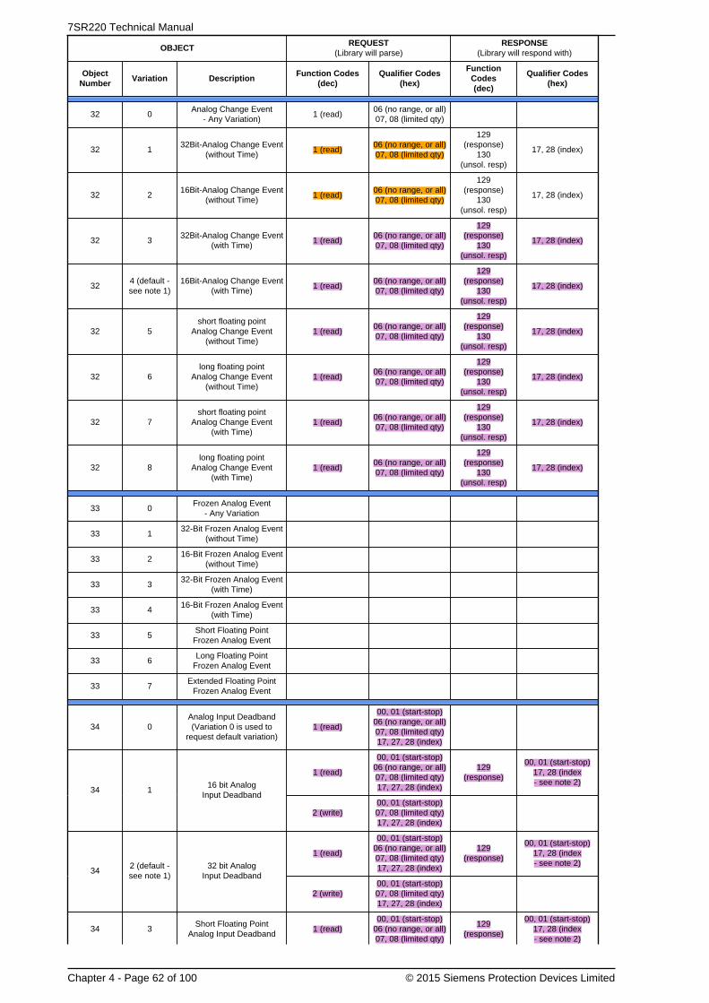
7SR220 Technical Manual
Chapter 4 - Page 62 of 100 © 2015 Siemens Protection Devices Limited
OBJECTREQUEST
(Library will parse)RESPONSE
(Library will respond with)
ObjectNumber
Variation DescriptionFunction Codes
(dec)Qualifier Codes
(hex)
FunctionCodes(dec)
Qualifier Codes(hex)
32 0Analog Change Event
- Any Variation)1 (read)
06 (no range, or all)07, 08 (limited qty)
32 132Bit-Analog Change Event
(without Time)1 (read)
06 (no range, or all)07, 08 (limited qty)
129(response)
130(unsol. resp)
17, 28 (index)
32 216Bit-Analog Change Event
(without Time)1 (read)
06 (no range, or all)07, 08 (limited qty)
129(response)
130(unsol. resp)
17, 28 (index)
32 332Bit-Analog Change Event
(with Time)1 (read)
06 (no range, or all)07, 08 (limited qty)
129(response)
130(unsol. resp)
17, 28 (index)
324 (default -see note 1)
16Bit-Analog Change Event(with Time)
1 (read)06 (no range, or all)07, 08 (limited qty)
129(response)
130(unsol. resp)
17, 28 (index)
32 5short floating point
Analog Change Event(without Time)
1 (read)06 (no range, or all)07, 08 (limited qty)
129(response)
130(unsol. resp)
17, 28 (index)
32 6long floating point
Analog Change Event(without Time)
1 (read)06 (no range, or all)07, 08 (limited qty)
129(response)
130(unsol. resp)
17, 28 (index)
32 7short floating point
Analog Change Event(with Time)
1 (read)06 (no range, or all)07, 08 (limited qty)
129(response)
130(unsol. resp)
17, 28 (index)
32 8long floating point
Analog Change Event(with Time)
1 (read)06 (no range, or all)07, 08 (limited qty)
129(response)
130(unsol. resp)
17, 28 (index)
33 0Frozen Analog Event
- Any Variation
33 132-Bit Frozen Analog Event
(without Time)
33 216-Bit Frozen Analog Event
(without Time)
33 332-Bit Frozen Analog Event
(with Time)
33 416-Bit Frozen Analog Event
(with Time)
33 5Short Floating PointFrozen Analog Event
33 6Long Floating Point
Frozen Analog Event
33 7Extended Floating Point
Frozen Analog Event
34 0Analog Input Deadband(Variation 0 is used to
request default variation)1 (read)
00, 01 (start-stop)06 (no range, or all)07, 08 (limited qty)17, 27, 28 (index)
1 (read)
00, 01 (start-stop)06 (no range, or all)07, 08 (limited qty)17, 27, 28 (index)
129(response)
00, 01 (start-stop)17, 28 (index- see note 2)
34 116 bit Analog
Input Deadband
2 (write)00, 01 (start-stop)07, 08 (limited qty)17, 27, 28 (index)
1 (read)
00, 01 (start-stop)06 (no range, or all)07, 08 (limited qty)17, 27, 28 (index)
129(response)
00, 01 (start-stop)17, 28 (index- see note 2)
342 (default -see note 1)
32 bit AnalogInput Deadband
2 (write)00, 01 (start-stop)07, 08 (limited qty)17, 27, 28 (index)
34 3Short Floating Point
Analog Input Deadband1 (read)
00, 01 (start-stop)06 (no range, or all)07, 08 (limited qty)
129(response)
00, 01 (start-stop)17, 28 (index- see note 2)

Chapter 4 - 7SR220 · Data Communications Definitions
© 2015 Siemens Protection Devices Limited Chapter 4 - Page 63 of 100
OBJECTREQUEST
(Library will parse)RESPONSE
(Library will respond with)
ObjectNumber
Variation DescriptionFunction Codes
(dec)Qualifier Codes
(hex)
FunctionCodes(dec)
Qualifier Codes(hex)
17, 27, 28 (index)
2 (write)00, 01 (start-stop)07, 08 (limited qty)17, 27, 28 (index)
50 0 Time and Date
1 (read) 07, 08 (limited qty)129
(response)07 (limited qty = 1)
501 (default -see note 1)
Time and Date
2 (write)00, 01 (start-stop)07, 08 (limited qty)17, 27, 28 (index)
50 3Time and Date Last
Recorded Time2 (write) 07 (limited qty)
51 1 Time and Date CTO
129(response)
130(unsol. resp)
(limited qty = 1)
51 2Unsynchronized
Time and Date CTO
129(response)
130(unsol. resp)
(limited qty = 1)
52 1 Time Delay Coarse129
(response)(limited qty = 1)
52 2 Time Delay Fine129
(response)(limited qty = 1)
60 0 Not Defined
60 1 Class 0 Data 1 (read) 06 (no range, or all)
1 (read)06 (no range, or all)07, 08 (limited qty)
60 2 Class 1 Data 20 (enbl. unsol.)21 (dab. unsol.)22 (assign class)
06 (no range, or all)
1 (read)06 (no range, or all)07, 08 (limited qty)
60 3 Class 2 Data 20 (enbl. unsol.)21 (dab. unsol.)22 (assign class)
06 (no range, or all)
1 (read)06 (no range, or all)07, 08 (limited qty)
60 4 Class 3 Data 20 (enbl. unsol.)21 (dab. unsol.)22 (assign class)
06 (no range, or all)
1 (read) 00, 01 (start-stop)129
(response)00, 01 (start-stop)
80 1 Internal Indications
2 (write)(see note 3)00 (start-
stop) index=7
No Object(function code only)
13 (cold restart)
No Object(function code only)
14 (warm restart)
No Object(function code only)
23 (delay meas.)
No Object(function code only)
24 (recordcurrent time)
Note 1: A Default variation refers to the variation responded when variation 0 is requested and/or in class 0, 1, 2, or3 scans. Default variations are configurable; however, default settings for the configuration parameters are indicatedin the table above.
Note 2: For static (non-change-event) objects, qualifiers 17 or 28 are only responded when a request is sent withqualifiers 17 or 28, respectively. Otherwise, static object requests sent with qualifiers 00, 01, 06, 07, or 08, will beresponded with qualifiers 00 or 01. (For change-event objects, qualifiers 17 or 28 are always responded.)
Note 3: Writes of Internal Indications are only supported for index 7 (Restart IIN1-7).

7SR220 Technical Manual
Chapter 4 - Page 64 of 100 © 2015 Siemens Protection Devices Limited
5.3 Point List
The tables below identify all the default data points provided by the implementation of the Triangle MicroWorks, Inc.DNP 3.0 Slave Source Code Library.
This protocol can be set to use any or all of the relays hardware interfaces (USB, Fibre Optic, RS232 and RS485).The relay can communicate simultaneously on all ports regardless of protocol used.
The Station Address of the port being used must be set to a suitable address within the range 0 - 65534 to enablecommunication. This can be set by the Communications Menu : COM n-xxxxx Station Address setting.
Communication via DNP3 over Ethernet requires external devices. Please refer to the documents TCPIP CatalogueSheet and TCPIP Interface Technical Guidance Notes for more information.
The information shown below is the default configuration. This can be modified using the CommunicationsConfiguration Editor tool, refer section 9 for details.
5.3.1 Binary Input Points
The default binary input event buffer size is set to allow 100 events.
Binary inputs are by default returned in a class zero interrogation.
Note, not all points listed here apply to all builds of devices.
Binary Input PointsStatic (Steady-State) Object Number: 1 (Packed Format)Change Event Object Number: 1 (w/o Time)Static Variation reported when variation 0 requested: 1 (Binary Input w/o status)
or 2 (Binary Input with status)Change Event Variation reported when variation 0 requested: 1 (Binary Input Change w/o Time)
or 2 (Binary Input Change with Absolute Time)or 3 (Binary Input Change with Relative Time)
FW#PointIndex
Name(Description)
Default Change EventAssigned Class(1, 2, 3 or none)
Default VariationStatic Object 1
Default VariationEvent Object 2
1 Binary Input 1 0,2 2 2
2 Binary Input 2 0,2 2 2
3 Binary Input 3 0,2 2 2
4 Binary Input 4 0,2 2 2
5 Binary Input 5 0,2 2 2
6 Binary Input 6 0,2 2 2
7 Binary Input 7 0,2 2 2
8 Binary Input 8 0,2 2 2
9 Binary Input 9 0,2 2 2
10 Binary Input 10 0,2 2 2
11 Binary Input 11 0,2 2 2
12 Binary Input 12 0,2 2 2
13 Binary Input 13 0,2 2 2
35 Remote Mode 0,2 2 2
36 Out Of Service Mode 0,2 2 2
37 Local Mode 0,2 2 2
38 Local & Remote 0,2 2 2
R7b-7c 40 General Trip 0,2 2 2
41 Trip Circuit Fail 0,2 2 2
42 Start/Pick-up L1 0,2 2 2

Chapter 4 - 7SR220 · Data Communications Definitions
© 2015 Siemens Protection Devices Limited Chapter 4 - Page 65 of 100
Binary Input PointsStatic (Steady-State) Object Number: 1 (Packed Format)Change Event Object Number: 1 (w/o Time)Static Variation reported when variation 0 requested: 1 (Binary Input w/o status)
or 2 (Binary Input with status)Change Event Variation reported when variation 0 requested: 1 (Binary Input Change w/o Time)
or 2 (Binary Input Change with Absolute Time)or 3 (Binary Input Change with Relative Time)
FW#PointIndex
Name(Description)
Default Change EventAssigned Class(1, 2, 3 or none)
Default VariationStatic Object 1
Default VariationEvent Object 2
43 Start/Pick-up L2 0,2 2 2
44 Start/Pick-up L3 0,2 2 2
45 General Start/Pick-up 0,2 2 2
46 VT Fuse Failure 0,2 2 2
47 Earth Fault Forward/Line 0,2 2 2
48 Earth Fault Reverse/Busbar 0,2 2 2
49 Start/Pick-up N 0,2 2 2
50 Fault Forward/Line 0,2 2 2
51 Fault Reverse/Busbar 0,2 2 2
52 51-1 0,2 2 2
53 50-1 0,2 2 2
54 51N-1 0,2 2 2
55 50N-1 0,2 2 2
56 51G-1 0,2 2 2
57 50G-1 0,2 2 2
58 51-2 0,2 2 2
59 50-2 0,2 2 2
60 51N-2 0,2 2 2
61 50N-2 0,2 2 2
62 51G-2 0,2 2 2
63 50G-2 0,2 2 2
64 60 CTS 0,2 2 2
65 46IT 0,2 2 2
66 46DT 0,2 2 2
67 47-1 0,2 2 2
68 47-2 0,2 2 2
69 46BC 0,2 2 2
70 27/59-1 0,2 2 2
71 27/59-2 0,2 2 2
72 27/59-3 0,2 2 2
73 27/59-4 0,2 2 2
74 59NIT 0,2 2 2
75 59NDT 0,2 2 2
76 81-1 0,2 2 2
77 81-2 0,2 2 2
78 81-3 0,2 2 2
79 81-4 0,2 2 2
80 Auto-reclose active 0,2 2 2
81 CB on by auto reclose 0,2 2 2
82 Reclaim 0,2 2 2
83 Lockout 0,2 2 2

7SR220 Technical Manual
Chapter 4 - Page 66 of 100 © 2015 Siemens Protection Devices Limited
Binary Input PointsStatic (Steady-State) Object Number: 1 (Packed Format)Change Event Object Number: 1 (w/o Time)Static Variation reported when variation 0 requested: 1 (Binary Input w/o status)
or 2 (Binary Input with status)Change Event Variation reported when variation 0 requested: 1 (Binary Input Change w/o Time)
or 2 (Binary Input Change with Absolute Time)or 3 (Binary Input Change with Relative Time)
FW#PointIndex
Name(Description)
Default Change EventAssigned Class(1, 2, 3 or none)
Default VariationStatic Object 1
Default VariationEvent Object 2
84 81-5 0,2 2 2
85 81-6 0,2 2 2
86 51-3 0,2 2 2
87 50-3 0,2 2 2
88 51N-3 0,2 2 2
89 50N-3 0,2 2 2
90 51G-3 0,2 2 2
91 50G-3 0,2 2 2
92 51-4 0,2 2 2
93 50-4 0,2 2 2
94 51N-4 0,2 2 2
95 50N-4 0,2 2 2
96 51G-4 0,2 2 2
97 50G-4 0,2 2 2
98 Cold Load Active 0,2 2 2
99 E/F Out 0,2 2 2
100 P/F Inst Protection Inhibited 0,2 2 2
101 E/F Inst Protection Inhibited 0,2 2 2
102 SEF Inst Protection Inhibited 0,2 2 2
103 Ext Inst Protection Inhibited 0,2 2 2
117 51SEF-1 0,2 2 2
118 50SEF-1 0,2 2 2
119 51SEF-2 0,2 2 2
120 50SEF-2 0,2 2 2
121 51SEF-3 0,2 2 2
122 50SEF-3 0,2 2 2
123 51SEF-4 0,2 2 2
124 50SEF-4 0,2 2 2
125 SEF Out 0,2 2 2
126 Trip Circuit Fail 1 0,2 2 2
127 Trip Circuit Fail 2 0,2 2 2
128 Trip Circuit Fail 3 0,2 2 2
129 CB Total Trip Count 0,2 2 2
130 CB Delta Trip Count 0,2 2 2
131 CB Count To AR Block 0,2 2 2
132 CB Frequent Ops Count 0,2 2 2
133 I^2t CB Wear 0,2 2 2
207 Close Circuit Fail 1 0,2 2 2
208 Close Circuit Fail 2 0,2 2 2
209 Close Circuit Fail 3 0,2 2 2
210 Close Circuit Fail 0,2 2 2
211 50BF Stage 1 0,2 2 2

Chapter 4 - 7SR220 · Data Communications Definitions
© 2015 Siemens Protection Devices Limited Chapter 4 - Page 67 of 100
Binary Input PointsStatic (Steady-State) Object Number: 1 (Packed Format)Change Event Object Number: 1 (w/o Time)Static Variation reported when variation 0 requested: 1 (Binary Input w/o status)
or 2 (Binary Input with status)Change Event Variation reported when variation 0 requested: 1 (Binary Input Change w/o Time)
or 2 (Binary Input Change with Absolute Time)or 3 (Binary Input Change with Relative Time)
FW#PointIndex
Name(Description)
Default Change EventAssigned Class(1, 2, 3 or none)
Default VariationStatic Object 1
Default VariationEvent Object 2
212 50BF Stage 2 0,2 2 2
213 49-Alarm 0,2 2 2
214 49-Trip 0,2 2 2
215 64H 0,2 2 2
216 Vx27/59 0,2 2 2
217 37-1 0,2 2 2
218 37-2 0,2 2 2
219 CB Alarm 0,2 2 2
225 General Alarm 1 0,2 2 2
226 General Alarm 2 0,2 2 2
227 General Alarm 3 0,2 2 2
228 General Alarm 4 0,2 2 2
229 General Alarm 5 0,2 2 2
230 General Alarm 6 0,2 2 2
231 General Alarm 7 0,2 2 2
232 General Alarm 8 0,2 2 2
233 General Alarm 9 0,2 2 2
234 General Alarm 10 0,2 2 2
235 General Alarm 11 0,2 2 2
236 General Alarm 12 0,2 2 2
237 Quick Logic E1 0,2 2 2
238 Quick Logic E2 0,2 2 2
239 Quick Logic E3 0,2 2 2
240 Quick Logic E4 0,2 2 2
241 Quick Logic E5 0,2 2 2
242 Quick Logic E6 0,2 2 2
243 Quick Logic E7 0,2 2 2
244 Quick Logic E8 0,2 2 2
245 Quick Logic E9 0,2 2 2
246 Quick Logic E10 0,2 2 2
247 Quick Logic E11 0,2 2 2
248 Quick Logic E12 0,2 2 2
249 Quick Logic E13 0,2 2 2
250 Quick Logic E14 0,2 2 2
251 Quick Logic E15 0,2 2 2
252 Quick Logic E16 0,2 2 2
269 60 CTS-I 0,2 2 2
270 81HBL2 0,2 2 2
271 37G-1 0,2 2 2
272 37G-2 0,2 2 2

7SR220 Technical Manual
Chapter 4 - Page 68 of 100 © 2015 Siemens Protection Devices Limited
Binary Input PointsStatic (Steady-State) Object Number: 1 (Packed Format)Change Event Object Number: 1 (w/o Time)Static Variation reported when variation 0 requested: 1 (Binary Input w/o status)
or 2 (Binary Input with status)Change Event Variation reported when variation 0 requested: 1 (Binary Input Change w/o Time)
or 2 (Binary Input Change with Absolute Time)or 3 (Binary Input Change with Relative Time)
FW#PointIndex
Name(Description)
Default Change EventAssigned Class(1, 2, 3 or none)
Default VariationStatic Object 1
Default VariationEvent Object 2
R7b-7c 274 37-PhA 0,2 2 2
R7b-7c 275 37-PhB 0,2 2 2
R7b-7c 276 37-PhC 0,2 2 2
R7b-7c 283 50BF-PhA 0,2 2 2
R7b-7c 284 50BF-PhB 0,2 2 2
R7b-7c 285 50BF-PhC 0,2 2 2
R7b-7c 286 50BF-EF 0,2 2 2
R7b-7c 287 79 Last Trip Lockout 0,2 2 2
R7b-7c 288 60 CTS-I-PhA 0,2 2 2
R7b-7c 289 60 CTS-I-PhB 0,2 2 2
R7b-7c 290 60 CTS-I-PhC 0,2 2 2
R7b-7c 291 Trip PhA 0,2 2 2
R7b-7c 292 Trip PhB 0,2 2 2
R7b-7c 293 Trip PhC 0,2 2 2
302 27/59 PhA 0,2 2 2
303 27/59 PhB 0,2 2 2
304 27/59 PhC 0,2 2 2
R7b-7c 310 General Alarm 13 0,2 2 2
R7b-7c 311 General Alarm 14 0,2 2 2
R7b-7c 312 General Alarm 15 0,2 2 2
R7b-7c 313 General Alarm 16 0,2 2 2
R7b-7c 314 General Alarm 17 0,2 2 2
R7b-7c 315 General Alarm 18 0,2 2 2
R7b-7c 316 General Alarm 19 0,2 2 2
R7b-7c 317 General Alarm 20 0,2 2 2
373 37SEF-1 0,2 2 2
374 37SEF-2 0,2 2 2
R7e-7c 387 25 System Split 0,2 2 2
R7e-7c 388 25 Live Line 0,2 2 2
R7e-7c 389 25 Live Bus 0,2 2 2
R7e-7c 390 25 Line U/V 0,2 2 2
R7e-7c 391 25 Bus U/V 0,2 2 2
R7e-7c 392 25 Voltage Dif > 0,2 2 2
R7e-7c 393 25 CS Slip Freq > 0,2 2 2
R7e-7c 394 25 SS Slip Freq > 0,2 2 2

Chapter 4 - 7SR220 · Data Communications Definitions
© 2015 Siemens Protection Devices Limited Chapter 4 - Page 69 of 100
Binary Input PointsStatic (Steady-State) Object Number: 1 (Packed Format)Change Event Object Number: 1 (w/o Time)Static Variation reported when variation 0 requested: 1 (Binary Input w/o status)
or 2 (Binary Input with status)Change Event Variation reported when variation 0 requested: 1 (Binary Input Change w/o Time)
or 2 (Binary Input Change with Absolute Time)or 3 (Binary Input Change with Relative Time)
FW#PointIndex
Name(Description)
Default Change EventAssigned Class(1, 2, 3 or none)
Default VariationStatic Object 1
Default VariationEvent Object 2
R7e-7c 395 25 COZ Slip Freq > 0,2 2 2
R7e-7c 396 25 In Sync 0,2 2 2
R7e-7c 397 25 CS In Progress 0,2 2 2
R7e-7c 398 25 SS In Progress 0,2 2 2
R7e-7c 399 25 COZ In Progress 0,2 2 2
R7e-7c 400 25 System Split LO 0,2 2 2
R7e-7c 401 60VTF-Bus 0,2 2 2
R7b-7c 411 Setting G1 selected 0,2 2 2
R7b-7c 412 Setting G2 selected 0,2 2 2
R7b-7c 413 Setting G3 selected 0,2 2 2
R7b-7c 414 Setting G4 selected 0,2 2 2
R7b-7c 415 Setting G5 selected 0,2 2 2
R7b-7c 416 Setting G6 selected 0,2 2 2
R7b-7c 417 Setting G7 selected 0,2 2 2
R7b-7c 418 Setting G8 selected 0,2 2 2
R7b-7c 420 79 AR In progress 0,2 2 2
R7b-7c 422 HotLine Working 0,2 2 2
R7b-7c 425 Inst Protection Out 0,2 2 2
R7b-7c 427 CB 1 0,2 2 2
R7e-7c 434 Man Override Sync 0,2 2 2
R7e-7c 435 79 Override Sync 0,2 2 2
R7b-7c 501 Virtual Input 1 0,2 2 2
R7b-7c 502 Virtual Input 2 0,2 2 2
R7b-7c 503 Virtual Input 3 0,2 2 2
R7b-7c 504 Virtual Input 4 0,2 2 2
R7b-7c 505 Virtual Input 5 0,2 2 2
R7b-7c 506 Virtual Input 6 0,2 2 2
R7b-7c 507 Virtual Input 7 0,2 2 2
R7b-7c 508 Virtual Input 8 0,2 2 2
R7b-7c 509 Virtual Input 9 0,2 2 2
R7b-7c 510 Virtual Input 10 0,2 2 2
R7b-7c 511 Virtual Input 11 0,2 2 2
R7b-7c 512 Virtual Input 12 0,2 2 2
R7b-7c 513 Virtual Input 13 0,2 2 2

7SR220 Technical Manual
Chapter 4 - Page 70 of 100 © 2015 Siemens Protection Devices Limited
Binary Input PointsStatic (Steady-State) Object Number: 1 (Packed Format)Change Event Object Number: 1 (w/o Time)Static Variation reported when variation 0 requested: 1 (Binary Input w/o status)
or 2 (Binary Input with status)Change Event Variation reported when variation 0 requested: 1 (Binary Input Change w/o Time)
or 2 (Binary Input Change with Absolute Time)or 3 (Binary Input Change with Relative Time)
FW#PointIndex
Name(Description)
Default Change EventAssigned Class(1, 2, 3 or none)
Default VariationStatic Object 1
Default VariationEvent Object 2
R7b-7c 514 Virtual Input 14 0,2 2 2
R7b-7c 515 Virtual Input 15 0,2 2 2
R7b-7c 516 Virtual Input 16 0,2 2 2
R7b-7c 601 LED 1 0,2 2 2
R7b-7c 602 LED 2 0,2 2 2
R7b-7c 603 LED 3 0,2 2 2
R7b-7c 604 LED 4 0,2 2 2
R7b-7c 605 LED 5 0,2 2 2
R7b-7c 606 LED 6 0,2 2 2
R7b-7c 607 LED 7 0,2 2 2
R7b-7c 608 LED 8 0,2 2 2
R7b-7c 609 LED 9 0,2 2 2
R7b-7c 610 LED 10 0,2 2 2
R7b-7c 611 LED 11 0,2 2 2
R7b-7c 612 LED 12 0,2 2 2
R7b-7c 613 LED 13 0,2 2 2
R7b-7c 614 LED 14 0,2 2 2
R7b-7c 615 LED 15 0,2 2 2
R7b-7c 616 LED 16 0,2 2 2
R7b-7c 701 LED PU 1 0,2 2 2
R7b-7c 702 LED PU 2 0,2 2 2
R7b-7c 703 LED PU 3 0,2 2 2
R7b-7c 704 LED PU 4 0,2 2 2
R7b-7c 705 LED PU 5 0,2 2 2
R7b-7c 706 LED PU 6 0,2 2 2
R7b-7c 707 LED PU 7 0,2 2 2
R7b-7c 708 LED PU 8 0,2 2 2
R7b-7c 709 LED PU 9 0,2 2 2
R7b-7c 710 LED PU 10 0,2 2 2
R7b-7c 711 LED PU 11 0,2 2 2
R7b-7c 712 LED PU 12 0,2 2 2
R7b-7c 713 LED PU 13 0,2 2 2
R7b-7c 714 LED PU 14 0,2 2 2
R7b-7c 715 LED PU 15 0,2 2 2

Chapter 4 - 7SR220 · Data Communications Definitions
© 2015 Siemens Protection Devices Limited Chapter 4 - Page 71 of 100
Binary Input PointsStatic (Steady-State) Object Number: 1 (Packed Format)Change Event Object Number: 1 (w/o Time)Static Variation reported when variation 0 requested: 1 (Binary Input w/o status)
or 2 (Binary Input with status)Change Event Variation reported when variation 0 requested: 1 (Binary Input Change w/o Time)
or 2 (Binary Input Change with Absolute Time)or 3 (Binary Input Change with Relative Time)
FW#PointIndex
Name(Description)
Default Change EventAssigned Class(1, 2, 3 or none)
Default VariationStatic Object 1
Default VariationEvent Object 2
R7b-7c 716 LED PU 16 0,2 2 2
R7b-7c 801 Binary Output 1 0,2 2 2
R7b-7c 802 Binary Output 2 0,2 2 2
R7b-7c 803 Binary Output 3 0,2 2 2
R7b-7c 804 Binary Output 4 0,2 2 2
R7b-7c 805 Binary Output 5 0,2 2 2
R7b-7c 806 Binary Output 6 0,2 2 2
R7b-7c 807 Binary Output 7 0,2 2 2
R7b-7c 808 Binary Output 8 0,2 2 2
R7b-7c 809 Binary Output 9 0,2 2 2
R7b-7c 810 Binary Output 10 0,2 2 2
R7b-7c 811 Binary Output 11 0,2 2 2
R7b-7c 812 Binary Output 12 0,2 2 2
R7b-7c 813 Binary Output 13 0,2 2 2
R7b-7c 814 Binary Output 14 0,2 2 2
R7b-7c 871 Cold Start 0,2 2 2
R7b-7c 872 Warm Start 0,2 2 2
R7b-7c 873 Re-Start 0,2 2 2
R7b-7c 874 Power On 0,2 2 2
R7b-7c 875 Expected Restart 0,2 2 2
R7b-7c 876 Unexpected Restart 0,2 2 2
R7b-7c 877 Reset Start Count 0,2 2 2
R7b-7c 890 CB 1 Opened 0,2 2 2
R7b-7c 891 CB 1 Closed 0,2 2 2
R7b-7c 900 User SP Command 1 0,2 2 2
R7b-7c 901 User SP Command 2 0,2 2 2
R7b-7c 902 User SP Command 3 0,2 2 2
R7b-7c 903 User SP Command 4 0,2 2 2
R7b-7c 904 User SP Command 5 0,2 2 2
R7b-7c 905 User SP Command 6 0,2 2 2
R7b-7c 906 User SP Command 7 0,2 2 2
R7b-7c 907 User SP Command 8 0,2 2 2
R7e-7c 1010 User Output 1 0,2 2 2
R7e-7c 1011 User Output 2 0,2 2 2

7SR220 Technical Manual
Chapter 4 - Page 72 of 100 © 2015 Siemens Protection Devices Limited
Binary Input PointsStatic (Steady-State) Object Number: 1 (Packed Format)Change Event Object Number: 1 (w/o Time)Static Variation reported when variation 0 requested: 1 (Binary Input w/o status)
or 2 (Binary Input with status)Change Event Variation reported when variation 0 requested: 1 (Binary Input Change w/o Time)
or 2 (Binary Input Change with Absolute Time)or 3 (Binary Input Change with Relative Time)
FW#PointIndex
Name(Description)
Default Change EventAssigned Class(1, 2, 3 or none)
Default VariationStatic Object 1
Default VariationEvent Object 2
R7e-7c 1012 User Output 3 0,2 2 2
R7e-7c 1013 User Output 4 0,2 2 2
R7e-7c 1014 User Output 5 0,2 2 2
R7e-7c 1015 User Output 6 0,2 2 2
R7e-7c 1016 User Output 7 0,2 2 2
R7e-7c 1017 User Output 8 0,2 2 2
R7e-7c 1018 User Output 9 0,2 2 2
R7e-7c 1019 User Output 10 0,2 2 2
R7e-7c 1020 User Output 11 0,2 2 2
R7e-7c 1021 User Output 12 0,2 2 2
R7e-7c 1022 User Output 13 0,2 2 2
R7e-7c 1023 User Output 14 0,2 2 2
R7e-7c 1024 User Output 15 0,2 2 2
R7e-7c 1025 User Output 16 0,2 2 2
R7e-7c 1026 User Output 17 0,2 2 2
R7e-7c 1027 User Output 18 0,2 2 2
R7e-7c 1028 User Output 19 0,2 2 2
R7e-7c 1029 User Output 20 0,2 2 2
R7e-7c 1030 User Output 21 0,2 2 2
R7e-7c 1031 User Output 22 0,2 2 2
R7e-7c 1032 User Output 23 0,2 2 2
R7e-7c 1033 User Output 24 0,2 2 2
R7e-7c 1034 User Output 25 0,2 2 2
R7e-7c 1035 User Output 26 0,2 2 2
R7e-7c 1036 User Output 27 0,2 2 2
R7e-7c 1037 User Output 28 0,2 2 2
R7e-7c 1038 User Output 29 0,2 2 2
R7e-7c 1039 User Output 30 0,2 2 2
R7e-7c 1040 User Output 31 0,2 2 2
R7e-7c 1041 User Output 32 0,2 2 2
R7f-7d 1061 E/F In 0,2 2 2
R7f-7d 1062 SEF In 0,2 2 2
R7f-7d 1063 CB DBI 0,2 2 2
R7f-7d 1064 CB Travelling 0,2 2 2
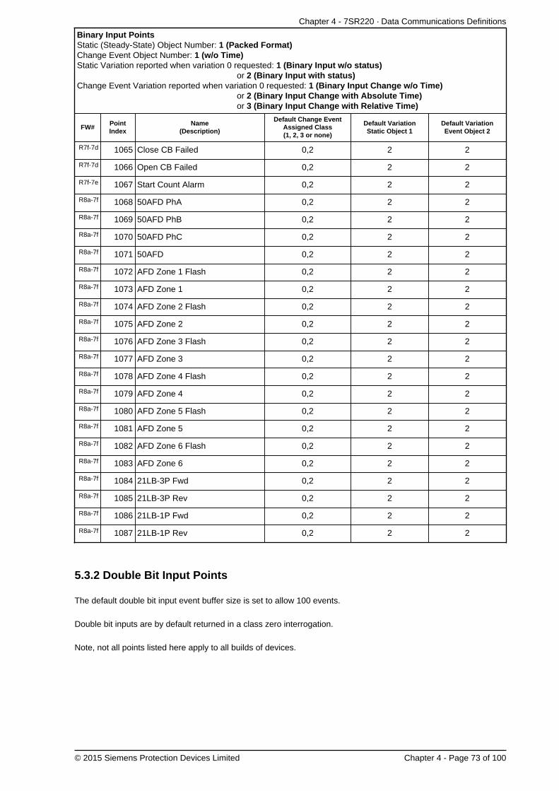
Chapter 4 - 7SR220 · Data Communications Definitions
© 2015 Siemens Protection Devices Limited Chapter 4 - Page 73 of 100
Binary Input PointsStatic (Steady-State) Object Number: 1 (Packed Format)Change Event Object Number: 1 (w/o Time)Static Variation reported when variation 0 requested: 1 (Binary Input w/o status)
or 2 (Binary Input with status)Change Event Variation reported when variation 0 requested: 1 (Binary Input Change w/o Time)
or 2 (Binary Input Change with Absolute Time)or 3 (Binary Input Change with Relative Time)
FW#PointIndex
Name(Description)
Default Change EventAssigned Class(1, 2, 3 or none)
Default VariationStatic Object 1
Default VariationEvent Object 2
R7f-7d 1065 Close CB Failed 0,2 2 2
R7f-7d 1066 Open CB Failed 0,2 2 2
R7f-7e 1067 Start Count Alarm 0,2 2 2
R8a-7f 1068 50AFD PhA 0,2 2 2
R8a-7f 1069 50AFD PhB 0,2 2 2
R8a-7f 1070 50AFD PhC 0,2 2 2
R8a-7f 1071 50AFD 0,2 2 2
R8a-7f 1072 AFD Zone 1 Flash 0,2 2 2
R8a-7f 1073 AFD Zone 1 0,2 2 2
R8a-7f 1074 AFD Zone 2 Flash 0,2 2 2
R8a-7f 1075 AFD Zone 2 0,2 2 2
R8a-7f 1076 AFD Zone 3 Flash 0,2 2 2
R8a-7f 1077 AFD Zone 3 0,2 2 2
R8a-7f 1078 AFD Zone 4 Flash 0,2 2 2
R8a-7f 1079 AFD Zone 4 0,2 2 2
R8a-7f 1080 AFD Zone 5 Flash 0,2 2 2
R8a-7f 1081 AFD Zone 5 0,2 2 2
R8a-7f 1082 AFD Zone 6 Flash 0,2 2 2
R8a-7f 1083 AFD Zone 6 0,2 2 2
R8a-7f 1084 21LB-3P Fwd 0,2 2 2
R8a-7f 1085 21LB-3P Rev 0,2 2 2
R8a-7f 1086 21LB-1P Fwd 0,2 2 2
R8a-7f 1087 21LB-1P Rev 0,2 2 2
5.3.2 Double Bit Input Points
The default double bit input event buffer size is set to allow 100 events.
Double bit inputs are by default returned in a class zero interrogation.
Note, not all points listed here apply to all builds of devices.
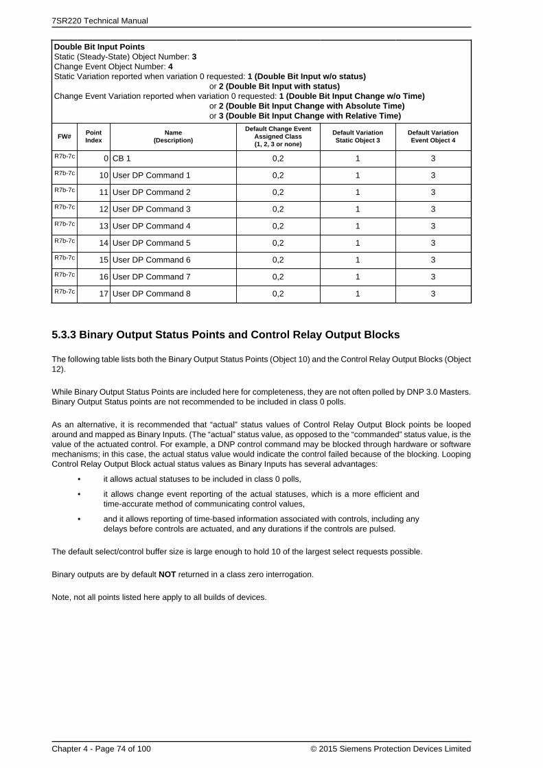
7SR220 Technical Manual
Chapter 4 - Page 74 of 100 © 2015 Siemens Protection Devices Limited
Double Bit Input PointsStatic (Steady-State) Object Number: 3Change Event Object Number: 4Static Variation reported when variation 0 requested: 1 (Double Bit Input w/o status)
or 2 (Double Bit Input with status)Change Event Variation reported when variation 0 requested: 1 (Double Bit Input Change w/o Time)
or 2 (Double Bit Input Change with Absolute Time)or 3 (Double Bit Input Change with Relative Time)
FW#PointIndex
Name(Description)
Default Change EventAssigned Class(1, 2, 3 or none)
Default VariationStatic Object 3
Default VariationEvent Object 4
R7b-7c 0 CB 1 0,2 1 3
R7b-7c 10 User DP Command 1 0,2 1 3
R7b-7c 11 User DP Command 2 0,2 1 3
R7b-7c 12 User DP Command 3 0,2 1 3
R7b-7c 13 User DP Command 4 0,2 1 3
R7b-7c 14 User DP Command 5 0,2 1 3
R7b-7c 15 User DP Command 6 0,2 1 3
R7b-7c 16 User DP Command 7 0,2 1 3
R7b-7c 17 User DP Command 8 0,2 1 3
5.3.3 Binary Output Status Points and Control Relay Output Blocks
The following table lists both the Binary Output Status Points (Object 10) and the Control Relay Output Blocks (Object12).
While Binary Output Status Points are included here for completeness, they are not often polled by DNP 3.0 Masters.Binary Output Status points are not recommended to be included in class 0 polls.
As an alternative, it is recommended that “actual” status values of Control Relay Output Block points be loopedaround and mapped as Binary Inputs. (The “actual” status value, as opposed to the “commanded” status value, is thevalue of the actuated control. For example, a DNP control command may be blocked through hardware or softwaremechanisms; in this case, the actual status value would indicate the control failed because of the blocking. LoopingControl Relay Output Block actual status values as Binary Inputs has several advantages:
• it allows actual statuses to be included in class 0 polls,
• it allows change event reporting of the actual statuses, which is a more efficient andtime-accurate method of communicating control values,
• and it allows reporting of time-based information associated with controls, including anydelays before controls are actuated, and any durations if the controls are pulsed.
The default select/control buffer size is large enough to hold 10 of the largest select requests possible.
Binary outputs are by default NOT returned in a class zero interrogation.
Note, not all points listed here apply to all builds of devices.

Chapter 4 - 7SR220 · Data Communications Definitions
© 2015 Siemens Protection Devices Limited Chapter 4 - Page 75 of 100
Binary Output Status PointsStatic (Steady-State) Object Number: 10Change Event Object Number: 11Control Relay Output Blocks (CROB) Object Number: 12Binary Output Command Event Object Number: 13Static Variation reported when variation 0 requested: 1 (Binary Output w/o status)
or 2 (Binary Output with status)Change Event Variation reported when variation 0 requested: 1 (Binary Output Event w/o Time)
or 2 (Binary Output Event with Time)Command Event Variation reported when variation 0 requested: 1 (Command Status w/o Time)
or 2 (Command Status with Time)
FW#PointIndex
Name(Description)
DefaultChangeEvent
AssignedClass(1, 2, 3
or none)
DefaultVariation
StaticObject 10
DefaultVariation
EventObject 11
DefaultCommand
EventObject 13Assigned
Class(1, 2, 3
or none)
DefaultVariation
CommandEvent
Object 13
CROBSupportedOperations
DefaultCROB
Operations
1 RL 1 0 2 2 0 1Pulse OnLatch OnClose
Pulse On
2 RL 2 0 2 2 0 1Pulse OnLatch OnClose
Pulse On
3 RL 3 0 2 2 0 1Pulse OnLatch OnClose
Pulse On
4 RL 4 0 2 2 0 1Pulse OnLatch OnClose
Pulse On
5 RL 5 0 2 2 0 1Pulse OnLatch OnClose
Pulse On
6 RL 6 0 2 2 0 1Pulse OnLatch OnClose
Pulse On
7 RL 7 0 2 2 0 1Pulse OnLatch OnClose
Pulse On
8 RL 8 0 2 2 0 1Pulse OnLatch OnClose
Pulse On
9 RL 9 0 2 2 0 1Pulse OnLatch OnClose
Pulse On
10 RL 10 0 2 2 0 1Pulse OnLatch OnClose
Pulse On
11 RL 11 0 2 2 0 1Pulse OnLatch OnClose
Pulse On
12 RL 12 0 2 2 0 1Pulse OnLatch OnClose
Pulse On
13 RL 13 0 2 2 0 1Pulse OnLatch OnClose
Pulse On
14 RL 14 0 2 2 0 1Pulse OnLatch OnClose
Pulse On
33LED reset, write onlylocation.
0 2 2 0 1Pulse OnLatch On
Pulse On

7SR220 Technical Manual
Chapter 4 - Page 76 of 100 © 2015 Siemens Protection Devices Limited
Binary Output Status PointsStatic (Steady-State) Object Number: 10Change Event Object Number: 11Control Relay Output Blocks (CROB) Object Number: 12Binary Output Command Event Object Number: 13Static Variation reported when variation 0 requested: 1 (Binary Output w/o status)
or 2 (Binary Output with status)Change Event Variation reported when variation 0 requested: 1 (Binary Output Event w/o Time)
or 2 (Binary Output Event with Time)Command Event Variation reported when variation 0 requested: 1 (Command Status w/o Time)
or 2 (Command Status with Time)
FW#PointIndex
Name(Description)
DefaultChangeEvent
AssignedClass(1, 2, 3
or none)
DefaultVariation
StaticObject 10
DefaultVariation
EventObject 11
DefaultCommand
EventObject 13Assigned
Class(1, 2, 3
or none)
DefaultVariation
CommandEvent
Object 13
CROBSupportedOperations
DefaultCROB
Operations
Close
34 Settings Group 1 0 2 2 0 1Pulse OnLatch OnClose
Latch On
35 Settings Group 2 0 2 2 0 1Pulse OnLatch OnClose
Latch On
36 Settings Group 3 0 2 2 0 1Pulse OnLatch OnClose
Latch On
37 Settings Group 4 0 2 2 0 1Pulse OnLatch OnClose
Latch On
38 Settings Group 5 0 2 2 0 1Pulse OnLatch OnClose
Latch On
39 Settings Group 6 0 2 2 0 1Pulse OnLatch OnClose
Latch On
40 Settings Group 7 0 2 2 0 1Pulse OnLatch OnClose
Latch On
41 Settings Group 8 0 2 2 0 1Pulse OnLatch OnClose
Latch On
42 Auto-reclose on/off 0 2 2 0 1
Pulse OnPulse OffLatch OnLatch OffCloseTrip
Pulse OnPulse OffLatch OnLatch Off
43 Hot Line Working on/off 0 2 2 0 1
Pulse OnPulse OffLatch OnLatch OffCloseTrip
Pulse OnPulse OffLatch OnLatch Off
44 E/F off/on 0 2 2 0 1
Pulse OnPulse OffLatch OnLatch OffCloseTrip
Pulse OnPulse OffLatch OnLatch Off
45 SEF off/on 0 2 2 0 1
Pulse OnPulse OffLatch OnLatch Off
Pulse OnPulse OffLatch OnLatch Off

Chapter 4 - 7SR220 · Data Communications Definitions
© 2015 Siemens Protection Devices Limited Chapter 4 - Page 77 of 100
Binary Output Status PointsStatic (Steady-State) Object Number: 10Change Event Object Number: 11Control Relay Output Blocks (CROB) Object Number: 12Binary Output Command Event Object Number: 13Static Variation reported when variation 0 requested: 1 (Binary Output w/o status)
or 2 (Binary Output with status)Change Event Variation reported when variation 0 requested: 1 (Binary Output Event w/o Time)
or 2 (Binary Output Event with Time)Command Event Variation reported when variation 0 requested: 1 (Command Status w/o Time)
or 2 (Command Status with Time)
FW#PointIndex
Name(Description)
DefaultChangeEvent
AssignedClass(1, 2, 3
or none)
DefaultVariation
StaticObject 10
DefaultVariation
EventObject 11
DefaultCommand
EventObject 13Assigned
Class(1, 2, 3
or none)
DefaultVariation
CommandEvent
Object 13
CROBSupportedOperations
DefaultCROB
Operations
CloseTrip
46 Inst Protection off/on 0 2 2 0 1
Pulse OnPulse OffLatch OnLatch OffCloseTrip
Pulse OnPulse OffLatch OnLatch Off
48Reset CB Total TripCount, write onlylocation.
0 2 2 0 1Pulse OnLatch OnClose
Pulse On
49Reset CB Delta TripCount, write onlylocation.
0 2 2 0 1Pulse OnLatch OnClose
Pulse On
50Reset CB Count To ARBlock, write only location.
0 2 2 0 1Pulse OnLatch OnClose
Pulse On
51Reset CB FrequentOps Count, write onlylocation.
0 2 2 0 1Pulse OnLatch OnClose
Pulse On
53 Reset I^2t CB Wear 0 2 2 0 1Pulse OnLatch OnClose
Pulse On
54 CB 1 0 2 2 0 1
Pulse OnPulse OffLatch OnLatch OffCloseTrip
Pulse OnPulse OffLatch OnLatch Off
55CB 1 Trip & Reclose,write only location.
0 2 2 0 1Pulse OnLatch OnClose
Pulse On
56CB 1 Trip & Lockout,write only location.
0 2 2 0 1Pulse OnLatch OnClose
Pulse On
59Demand metering reset,write only location.
0 2 2 0 1Pulse OnLatch OnClose
Pulse On
87 Reset Energy Meters 0 2 2 0 1Pulse OnLatch OnClose
Pulse On
88 Remote mode 0 2 2 0 1Pulse OnLatch OnClose
Pulse On
89 Service mode 0 2 2 0 1Pulse OnLatch On
Pulse On

7SR220 Technical Manual
Chapter 4 - Page 78 of 100 © 2015 Siemens Protection Devices Limited
Binary Output Status PointsStatic (Steady-State) Object Number: 10Change Event Object Number: 11Control Relay Output Blocks (CROB) Object Number: 12Binary Output Command Event Object Number: 13Static Variation reported when variation 0 requested: 1 (Binary Output w/o status)
or 2 (Binary Output with status)Change Event Variation reported when variation 0 requested: 1 (Binary Output Event w/o Time)
or 2 (Binary Output Event with Time)Command Event Variation reported when variation 0 requested: 1 (Command Status w/o Time)
or 2 (Command Status with Time)
FW#PointIndex
Name(Description)
DefaultChangeEvent
AssignedClass(1, 2, 3
or none)
DefaultVariation
StaticObject 10
DefaultVariation
EventObject 11
DefaultCommand
EventObject 13Assigned
Class(1, 2, 3
or none)
DefaultVariation
CommandEvent
Object 13
CROBSupportedOperations
DefaultCROB
Operations
Close
90 Local mode 0 2 2 0 1Pulse OnLatch OnClose
Pulse On
91 Local & Remote 0 2 2 0 1Pulse OnLatch OnClose
Pulse On
R7e-7c 92Man Override Sync on/off
0 2 2 0 1
Pulse OnPulse OffLatch OnLatch OffCloseTrip
Pulse OnPulse OffLatch OnLatch Off
R7e-7c 93 79 Override Sync on/off 0 2 2 0 1
Pulse OnPulse OffLatch OnLatch OffCloseTrip
Pulse OnPulse OffLatch OnLatch Off
R7b-7c 94Reset CB Phase ATrip Count, write onlylocation.
0 2 2 0 1Pulse OnLatch OnClose
Pulse On
R7b-7c 95Reset CB Phase BTrip Count, write onlylocation.
0 2 2 0 1Pulse OnLatch OnClose
Pulse On
R7b-7c 96Reset CB Phase CTrip Count, write onlylocation.
0 2 2 0 1Pulse OnLatch OnClose
Pulse On
R7b-7c 97Reset CB EF Trip Count,write only location.
0 2 2 0 1Pulse OnLatch OnClose
Pulse On
R7b-7c 98Reset Start Count(Action)
0 2 2 0 1Pulse OnLatch OnClose
Pulse OnLatch On
R7b-7c 99 User SP Command 1. 0 2 2 0 1Pulse OnLatch OnClose
Pulse On
R7b-7c 100 User SP Command 2. 0 2 2 0 1Pulse OnLatch OnClose
Pulse On
R7b-7c 101 User SP Command 3. 0 2 2 0 1Pulse OnLatch OnClose
Pulse On
R7b-7c 102 User SP Command 4. 0 2 2 0 1Pulse OnLatch OnClose
Pulse On

Chapter 4 - 7SR220 · Data Communications Definitions
© 2015 Siemens Protection Devices Limited Chapter 4 - Page 79 of 100
Binary Output Status PointsStatic (Steady-State) Object Number: 10Change Event Object Number: 11Control Relay Output Blocks (CROB) Object Number: 12Binary Output Command Event Object Number: 13Static Variation reported when variation 0 requested: 1 (Binary Output w/o status)
or 2 (Binary Output with status)Change Event Variation reported when variation 0 requested: 1 (Binary Output Event w/o Time)
or 2 (Binary Output Event with Time)Command Event Variation reported when variation 0 requested: 1 (Command Status w/o Time)
or 2 (Command Status with Time)
FW#PointIndex
Name(Description)
DefaultChangeEvent
AssignedClass(1, 2, 3
or none)
DefaultVariation
StaticObject 10
DefaultVariation
EventObject 11
DefaultCommand
EventObject 13Assigned
Class(1, 2, 3
or none)
DefaultVariation
CommandEvent
Object 13
CROBSupportedOperations
DefaultCROB
Operations
R7b-7c 103 User SP Command 5. 0 2 2 0 1Pulse OnLatch OnClose
Pulse On
R7b-7c 104 User SP Command 6. 0 2 2 0 1Pulse OnLatch OnClose
Pulse On
R7b-7c 105 User SP Command 7. 0 2 2 0 1Pulse OnLatch OnClose
Pulse On
R7b-7c 106 User SP Command 8. 0 2 2 0 1Pulse OnLatch OnClose
Pulse On
R7b-7c 107 User DP Command 1. 0 2 2 0 1
Pulse OnPulse OffLatch OnLatch OffCloseTrip
Pulse OnPulse Off
R7b-7c 108 User DP Command 2. 0 2 2 0 1
Pulse OnPulse OffLatch OnLatch OffCloseTrip
Pulse OnPulse Off
R7b-7c 109 User DP Command 3. 0 2 2 0 1
Pulse OnPulse OffLatch OnLatch OffCloseTrip
Pulse OnPulse Off
R7b-7c 110 User DP Command 4. 0 2 2 0 1
Pulse OnPulse OffLatch OnLatch OffCloseTrip
Pulse OnPulse Off
R7b-7c 111 User DP Command 5. 0 2 2 0 1
Pulse OnPulse OffLatch OnLatch OffCloseTrip
Pulse OnPulse Off
R7b-7c 112 User DP Command 6. 0 2 2 0 1
Pulse OnPulse OffLatch OnLatch OffClose
Pulse OnPulse Off

7SR220 Technical Manual
Chapter 4 - Page 80 of 100 © 2015 Siemens Protection Devices Limited
Binary Output Status PointsStatic (Steady-State) Object Number: 10Change Event Object Number: 11Control Relay Output Blocks (CROB) Object Number: 12Binary Output Command Event Object Number: 13Static Variation reported when variation 0 requested: 1 (Binary Output w/o status)
or 2 (Binary Output with status)Change Event Variation reported when variation 0 requested: 1 (Binary Output Event w/o Time)
or 2 (Binary Output Event with Time)Command Event Variation reported when variation 0 requested: 1 (Command Status w/o Time)
or 2 (Command Status with Time)
FW#PointIndex
Name(Description)
DefaultChangeEvent
AssignedClass(1, 2, 3
or none)
DefaultVariation
StaticObject 10
DefaultVariation
EventObject 11
DefaultCommand
EventObject 13Assigned
Class(1, 2, 3
or none)
DefaultVariation
CommandEvent
Object 13
CROBSupportedOperations
DefaultCROB
Operations
Trip
R7b-7c 113 User DP Command 7. 0 2 2 0 1
Pulse OnPulse OffLatch OnLatch OffCloseTrip
Pulse OnPulse Off
R7b-7c 114 User DP Command 8. 0 2 2 0 1
Pulse OnPulse OffLatch OnLatch OffCloseTrip
Pulse OnPulse Off
R7b-7c 115 CB-1 Open 0 2 2 0 1Pulse OnLatch OnClose
Pulse OnLatch On
R7b-7c 116 CB-1 Close 0 2 2 0 1Pulse OnLatch OnClose
Pulse OnLatch On
5.3.4 Counters
The following table lists both Binary Counters (Object 20) and Frozen Counters (Object 21). When a freeze functionis performed on a Binary Counter point, the frozen value is available in the corresponding Frozen Counter point. Thedefault Binary Counter and Frozen Counter event buffer sizes are set to 30.
The “Default Deadband,” and the “Default Change Event Assigned Class” columns are used to represent the absoluteamount by which the point must change before a Counter change event will be generated, and once generated inwhich class poll (1, 2, 3, or none) will the change event be reported.
The default counter event buffer size is set 30. The counter event mode is set to Most Recent, only most recent eventfor each point is stored.
Counters are by default returned in a class zero interrogation.
Note, not all points listed here apply to all builds of devices.

Chapter 4 - 7SR220 · Data Communications Definitions
© 2015 Siemens Protection Devices Limited Chapter 4 - Page 81 of 100
CountersStatic (Steady-State) Object Number: 20Change Event Object Number: 22Static Variation reported when variation 0 requested: 1 (32-Bit Counter with Flag)
or 2 (16-Bit Counter with Flag)or 5 (32-Bit Counter w/o Flag)or 6 (16-Bit Counter w/o Flag)
Change Event Variation reported when variation 0 requested: 1 (32-Bit Counter Event with Flag)or 2 (16-Bit Counter Event with Flag)or 5 (32-Bit Counter Event with Flag and Time)or 6 (16-Bit Counter Event with Flag and Time)
Frozen CountersStatic (Steady-State) Object Number: 21Change Event Object Number: 23Static Variation reported when variation 0 requested: 1 (32-Bit Frozen Counter with Flag)
or 2 (16-Bit Frozen Counter with Flag)or 5 (32-Bit Frozen Counter with Flag and Time)or 6 (16-Bit Frozen Counter with Flag and Time)or 9 (32-Bit Frozen Counter w/o Flag)or 10 (16-Bit Frozen Counter w/o Flag)
Change Event Variation reported when variation 0 requested: 1 (32-Bit Frozen Counter Event with Flag)or 2 (16-Bit Frozen Counter Event with Flag)or 5 (32-Bit Frozen Counter Event with Flag and Time)or 6 (16-Bit Frozen Counter Event with Flag and Time)
Counter Frozen Counter
FW#PointIndex
Name(Description)
DefaultChangeEvent
AssignedClass(1, 2, 3
or none)
DefaultVariation
StaticObject 20
DefaultVariation
EventObject 22 D
ead
ban
d
Is R
eset
tab
le
IsF
reez
able
DefaultChangeEvent
AssignedClass(1, 2, 3
or none)
DefaultVariation
StaticObject 21
DefaultVariation
EventObject 23
R7b-7c 0 Waveform Records 0,3 5 1 1 0,2 9 1
R7b-7c 1 Fault Records 0,3 5 1 1 0,2 9 1
R7b-7c 2 Event Records 0,3 5 1 1 0,2 9 1
R7b-7c 3 Data Log Records 0,3 5 1 1 0,2 9 1
R7b-7c 5 StartCount 0,3 5 1 1 0,2 9 1
R7b-7c 6 Start Count Target 0,3 5 1 1 0,2 9 1
R7b-7c 7 Active Setting Group 0,3 5 1 1 0,2 9 1
R7b-7c 11 CB Total Trip Count 0,3 5 1 1 0,2 9 1
R7b-7c 12 CB Ph A Trip Count 0,3 5 1 1 0,2 9 1
R7b-7c 13 CB Ph B Trip Count 0,3 5 1 1 0,2 9 1
R7b-7c 14 CB Ph C Trip Count 0,3 5 1 1 0,2 9 1
R7b-7c 15 CB E/F Trip Count 0,3 5 1 1 0,2 9 1
R7b-7c 16 CB Delta Trip Count 0,3 5 1 1 0,2 9 1
R7b-7c 17 CB Count To AR Block 0,3 5 1 1 0,2 9 1
R7b-7c 18 CB Frequent Ops Count 0,3 5 1 1 0,2 9 1
R7b-7c 21 E1 Counter 0,3 5 1 1 0,2 9 1
R7b-7c 22 E2 Counter 0,3 5 1 1 0,2 9 1
R7b-7c 23 E3 Counter 0,3 5 1 1 0,2 9 1
R7b-7c 24 E4 Counter 0,3 5 1 1 0,2 9 1
R7b-7c 25 E5 Counter 0,3 5 1 1 0,2 9 1
R7b-7c 26 E6 Counter 0,3 5 1 1 0,2 9 1

7SR220 Technical Manual
Chapter 4 - Page 82 of 100 © 2015 Siemens Protection Devices Limited
CountersStatic (Steady-State) Object Number: 20Change Event Object Number: 22Static Variation reported when variation 0 requested: 1 (32-Bit Counter with Flag)
or 2 (16-Bit Counter with Flag)or 5 (32-Bit Counter w/o Flag)or 6 (16-Bit Counter w/o Flag)
Change Event Variation reported when variation 0 requested: 1 (32-Bit Counter Event with Flag)or 2 (16-Bit Counter Event with Flag)or 5 (32-Bit Counter Event with Flag and Time)or 6 (16-Bit Counter Event with Flag and Time)
Frozen CountersStatic (Steady-State) Object Number: 21Change Event Object Number: 23Static Variation reported when variation 0 requested: 1 (32-Bit Frozen Counter with Flag)
or 2 (16-Bit Frozen Counter with Flag)or 5 (32-Bit Frozen Counter with Flag and Time)or 6 (16-Bit Frozen Counter with Flag and Time)or 9 (32-Bit Frozen Counter w/o Flag)or 10 (16-Bit Frozen Counter w/o Flag)
Change Event Variation reported when variation 0 requested: 1 (32-Bit Frozen Counter Event with Flag)or 2 (16-Bit Frozen Counter Event with Flag)or 5 (32-Bit Frozen Counter Event with Flag and Time)or 6 (16-Bit Frozen Counter Event with Flag and Time)
Counter Frozen Counter
FW#PointIndex
Name(Description)
DefaultChangeEvent
AssignedClass(1, 2, 3
or none)
DefaultVariation
StaticObject 20
DefaultVariation
EventObject 22 D
ead
ban
d
Is R
eset
tab
le
IsF
reez
able
DefaultChangeEvent
AssignedClass(1, 2, 3
or none)
DefaultVariation
StaticObject 21
DefaultVariation
EventObject 23
R7b-7c 27 E7 Counter 0,3 5 1 1 0,2 9 1
R7b-7c 28 E8 Counter 0,3 5 1 1 0,2 9 1
R7b-7c 29 E9 Counter 0,3 5 1 1 0,2 9 1
R7b-7c 30 E10 Counter 0,3 5 1 1 0,2 9 1
R7b-7c 31 E11 Counter 0,3 5 1 1 0,2 9 1
R7b-7c 32 E12 Counter 0,3 5 1 1 0,2 9 1
R7b-7c 33 E13 Counter 0,3 5 1 1 0,2 9 1
R7b-7c 34 E14 Counter 0,3 5 1 1 0,2 9 1
R7b-7c 35 E15 Counter 0,3 5 1 1 0,2 9 1
R7b-7c 36 E16 Counter 0,3 5 1 1 0,2 9 1
5.3.5 Analog Inputs
The following table lists Analog Inputs (Object 30). It is important to note that 16-bit and 32-bit variations of AnalogInputs, Analog Output Control Blocks, and Analog Output Statuses are transmitted through DNP as signed numbers.
The “Default Deadband,” and the “Default Change Event Assigned Class” columns are used to represent the absoluteamount by which the point must change before an Analog change event will be generated, and once generated inwhich class poll (1, 2, 3, or none) will the change event be reported.
The default analog input event buffer size is set 30. The analog input event mode is set to Most Recent, only mostrecent event for each point is stored.
Analog inputs are by default returned in a class zero interrogation.
Note, not all points listed here apply to all builds of devices.

Chapter 4 - 7SR220 · Data Communications Definitions
© 2015 Siemens Protection Devices Limited Chapter 4 - Page 83 of 100
Analog InputsStatic (Steady-State) Object Number: 30Change Event Object Number: 32Analog Input Deadband: 34Static Variation reported when variation 0 requested: 1 (32-Bit Analog Input with Flag)
or 2 (16-Bit Analog Input with Flag)or 3 (32-Bit Analog Input w/o Flag)or 4 (16-Bit Analog Input w/o Flag)or 5 (Single Precision, floating point Analog Input with Flag)
Change Event Variation reported when variation 0 requested: 1 (32-Bit Analog Change Event w/o Time)or 2 (16-Bit Analog Input w/o Time)or 3 (32-Bit Analog Input with Time)or 4 (16-Bit Analog Input with Time)or 5 (Single Precision, floating point Analog Input w/o Time)or 7 (Single Precision, floating point Analog Input with Time)
Analog Input Reporting Deadband Variation reported when variation 0 requested: 1 (16-Bit)or 2 (32-Bit)or 3 (Single Precision, floating point)
FW#PointIndex
Name(Description)
DefaultChange Event
Assigned Class(1, 2, 3 or none)
DefaultVariation
StaticObject 30
DefaultVariation
EventObject 32
DefaultMultiplier
DefaultDeadband
0 Frequency 0,3 2 4 100.000 1.000
1 Vab Primary 0,3 2 4 0.010 100.000
2 Vbc Primary 0,3 2 4 0.010 100.000
3 Vca Primary 0,3 2 4 0.010 100.000
4 Va Primary 0,3 2 4 0.010 100.000
5 Vb Primary 0,3 2 4 0.010 100.000
6 Vc Primary 0,3 2 4 0.010 100.000
7 Va Secondary 0,3 2 4 10.000 1.000
8 Vb Secondary 0,3 2 4 10.000 1.000
9 Vc Secondary 0,3 2 4 10.000 1.000
21 Vzps 0,3 2 4 10.000 1.000
22 Vpps 0,3 2 4 10.000 1.000
23 Vnps 0,3 2 4 10.000 1.000
31 Ia Primary 0,3 2 4 1.000 100.000
32 Ib Primary 0,3 2 4 1.000 100.000
33 Ic Primary 0,3 2 4 1.000 100.000
34 Ia Secondary 0,3 2 4 100.000 0.100
35 Ib Secondary 0,3 2 4 100.000 0.100
36 Ic Secondary 0,3 2 4 100.000 0.100
37 Ia Nominal 0,3 2 4 100.000 0.100
38 Ib Nominal 0,3 2 4 100.000 0.100
39 Ic Nominal 0,3 2 4 100.000 0.100
43 In Primary 0,3 2 4 1.000 100.000
44 In Secondary 0,3 2 4 100.000 0.100
45 In Nominal 0,3 2 4 100.000 0.100
46 Ig Primary 0,3 2 4 1.000 100.000
47 Ig Secondary 0,3 2 4 1000.000 0.100
48 Ig Nominal 0,3 2 4 1000.000 0.100
51 Izps Nominal 0,3 2 4 100.000 0.100
52 Ipps Nominal 0,3 2 4 100.000 0.100
53 Inps Nominal 0,3 2 4 100.000 0.100
57 Active Power A 0,3 2 4 0.000 1000000.000

7SR220 Technical Manual
Chapter 4 - Page 84 of 100 © 2015 Siemens Protection Devices Limited
Analog InputsStatic (Steady-State) Object Number: 30Change Event Object Number: 32Analog Input Deadband: 34Static Variation reported when variation 0 requested: 1 (32-Bit Analog Input with Flag)
or 2 (16-Bit Analog Input with Flag)or 3 (32-Bit Analog Input w/o Flag)or 4 (16-Bit Analog Input w/o Flag)or 5 (Single Precision, floating point Analog Input with Flag)
Change Event Variation reported when variation 0 requested: 1 (32-Bit Analog Change Event w/o Time)or 2 (16-Bit Analog Input w/o Time)or 3 (32-Bit Analog Input with Time)or 4 (16-Bit Analog Input with Time)or 5 (Single Precision, floating point Analog Input w/o Time)or 7 (Single Precision, floating point Analog Input with Time)
Analog Input Reporting Deadband Variation reported when variation 0 requested: 1 (16-Bit)or 2 (32-Bit)or 3 (Single Precision, floating point)
FW#PointIndex
Name(Description)
DefaultChange Event
Assigned Class(1, 2, 3 or none)
DefaultVariation
StaticObject 30
DefaultVariation
EventObject 32
DefaultMultiplier
DefaultDeadband
58 Active Power B 0,3 2 4 0.000 1000000.000
59 Active Power C 0,3 2 4 0.000 1000000.000
60 P (3P) 0,3 2 4 0.000 1000000.000
61 Reactive Power A 0,3 2 4 0.000 1000000.000
62 Reactive Power B 0,3 2 4 0.000 1000000.000
63 Reactive Power C 0,3 2 4 0.000 1000000.000
64 Q (3P) 0,3 2 4 0.000 1000000.000
65 Apparent Power A 0,3 2 4 0.000 1000000.000
66 Apparent Power B 0,3 2 4 0.000 1000000.000
67 Apparent Power C 0,3 2 4 0.000 1000000.000
68 S (3P) 0,3 2 4 0.000 1000000.000
71 Power Factor A 0,3 2 4 1000.000 0.100
72 Power Factor B 0,3 2 4 1000.000 0.100
73 Power Factor C 0,3 2 4 1000.000 0.100
74 Power Factor(3P) 0,3 2 4 1000.000 0.100
75 Act Energy Exp 0,3 1 3 1.000 Disabled
76 Act Energy Imp 0,3 1 3 1.000 Disabled
77 React Energy Exp 0,3 1 3 1.000 Disabled
78 React Energy Imp 0,3 1 3 1.000 Disabled
81 Thermal Status Ph A 0,1 4 4 100.000 1.000
82 Thermal Status Ph B 0,1 4 4 100.000 1.000
83 Thermal Status Ph C 0,1 4 4 100.000 1.000
95 Active Setting Group 0,3 2 4 1.000 1.000
99 Vab Secondary 0,3 2 4 10.000 1.000
100 Vbc Secondary 0,3 2 4 10.000 1.000
101 Vca Secondary 0,3 2 4 10.000 1.000
102 Vn Primary 0,3 2 4 0.010 100.000
103 Vn Secondary 0,3 2 4 10.000 1.000
105 Vx Primary 0,3 2 4 0.010 100.000
106 Vx Secondary 0,3 2 4 10.000 1.000
108 I Phase A Max 0,3 2 4 1.000 100.000
109 I Phase B Max 0,3 2 4 1.000 100.000
110 I Phase C Max 0,3 2 4 1.000 100.000
111 P 3P Max 0,3 2 4 0.000 1000000.000

Chapter 4 - 7SR220 · Data Communications Definitions
© 2015 Siemens Protection Devices Limited Chapter 4 - Page 85 of 100
Analog InputsStatic (Steady-State) Object Number: 30Change Event Object Number: 32Analog Input Deadband: 34Static Variation reported when variation 0 requested: 1 (32-Bit Analog Input with Flag)
or 2 (16-Bit Analog Input with Flag)or 3 (32-Bit Analog Input w/o Flag)or 4 (16-Bit Analog Input w/o Flag)or 5 (Single Precision, floating point Analog Input with Flag)
Change Event Variation reported when variation 0 requested: 1 (32-Bit Analog Change Event w/o Time)or 2 (16-Bit Analog Input w/o Time)or 3 (32-Bit Analog Input with Time)or 4 (16-Bit Analog Input with Time)or 5 (Single Precision, floating point Analog Input w/o Time)or 7 (Single Precision, floating point Analog Input with Time)
Analog Input Reporting Deadband Variation reported when variation 0 requested: 1 (16-Bit)or 2 (32-Bit)or 3 (Single Precision, floating point)
FW#PointIndex
Name(Description)
DefaultChange Event
Assigned Class(1, 2, 3 or none)
DefaultVariation
StaticObject 30
DefaultVariation
EventObject 32
DefaultMultiplier
DefaultDeadband
112 Q 3P Max 0,3 2 4 0.000 1000000.000
113 Ig Max 0,3 2 4 1.000 100.000
115 Isef Primary 0,3 2 4 1.000 10.000
116 Isef Secondary 0,3 2 4 1000.000 0.050
117 Isef Nominal 0,3 2 4 1000.000 0.050
R7e-7c 118 Fault Distance Percent 0,3 2 4 100.000 Disabled
R7e-7c 119 Fault Reactance 0,3 2 4 1000.000 Disabled
135 CB Total Trip Count 0,3 1 3 1.000 1.000
136 CB Delta Trip Count 0,3 1 3 1.000 1.000
137 CB Count To AR Block 0,3 1 3 1.000 1.000
138 CB Frequent Ops Count 0,3 1 3 1.000 1.000
R7e-7c 162 Phase Diff 0,3 2 4 100.000 1.000
R7e-7c 163 Slip Freq 0,3 2 4 100.000 1.000
R7e-7c 164 Voltage Diff 0,3 2 4 100.000 1.000
R7b-7c 165 Ia Last Trip 0,3 1 3 1.000 Disabled
R7b-7c 166 Ib Last Trip 0,3 1 3 1.000 Disabled
R7b-7c 167 Ic Last Trip 0,3 1 3 1.000 Disabled
168 Va Last Trip 0,3 1 3 1.000 Disabled
169 Vb Last Trip 0,3 1 3 1.000 Disabled
170 Vc Last Trip 0,3 1 3 1.000 Disabled
R7b-7c 171 In Last Trip 0,3 1 3 1.000 Disabled
R7b-7c 172 Ig Last Trip 0,3 1 3 1.000 Disabled
173 Isef Last Trip 0,3 1 3 1.000 Disabled
174 V Phase A Max 0,3 2 4 0.010 100.000
175 V Phase B Max 0,3 2 4 0.010 100.000
176 V Phase C Max 0,3 2 4 0.010 100.000
177 V Phase AB Max 0,3 2 4 0.010 100.000
178 V Phase BC Max 0,3 2 4 0.010 100.000
179 V Phase CA Max 0,3 2 4 0.010 100.000
R7b-7c 180 CB Ph A Trip Count 0,3 1 3 1.000 1.000
R7b-7c 181 CB Ph B Trip Count 0,3 1 3 1.000 1.000

7SR220 Technical Manual
Chapter 4 - Page 86 of 100 © 2015 Siemens Protection Devices Limited
Analog InputsStatic (Steady-State) Object Number: 30Change Event Object Number: 32Analog Input Deadband: 34Static Variation reported when variation 0 requested: 1 (32-Bit Analog Input with Flag)
or 2 (16-Bit Analog Input with Flag)or 3 (32-Bit Analog Input w/o Flag)or 4 (16-Bit Analog Input w/o Flag)or 5 (Single Precision, floating point Analog Input with Flag)
Change Event Variation reported when variation 0 requested: 1 (32-Bit Analog Change Event w/o Time)or 2 (16-Bit Analog Input w/o Time)or 3 (32-Bit Analog Input with Time)or 4 (16-Bit Analog Input with Time)or 5 (Single Precision, floating point Analog Input w/o Time)or 7 (Single Precision, floating point Analog Input with Time)
Analog Input Reporting Deadband Variation reported when variation 0 requested: 1 (16-Bit)or 2 (32-Bit)or 3 (Single Precision, floating point)
FW#PointIndex
Name(Description)
DefaultChange Event
Assigned Class(1, 2, 3 or none)
DefaultVariation
StaticObject 30
DefaultVariation
EventObject 32
DefaultMultiplier
DefaultDeadband
R7b-7c 182 CB Ph C Trip Count 0,3 1 3 1.000 1.000
R7b-7c 183 CB E/F Trip Count 0,3 1 3 1.000 1.000
R7b-7c 184 CB Wear A 0,3 1 3 0.000 1000000.000
R7b-7c 185 CB Wear B 0,3 1 3 0.000 1000000.000
R7b-7c 186 CB Wear C 0,3 1 3 0.000 1000000.000
R7b-7c 187 CB Wear A Remaining 0,3 1 3 1.000 1.000
R7b-7c 188 CB Wear B Remaining 0,3 1 3 1.000 1.000
R7b-7c 189 CB Wear C Remaining 0,3 1 3 1.000 1.000
R7b-7c 190 CB Wear Minimum 0,3 1 3 1.000 1.000
R7e-7c 191 Fault Distance Perunit 0,3 5 7 0.001 1.000
R7b-7c 196 Frequency Max 0,3 2 4 100.000 1.000
197 S 3P Max 0,3 2 4 0.000 1000000.000
R7f-7d 318 Sec Active Power A 0,3 2 4 1.000 10.000
R7f-7d 319 Sec Active Power B 0,3 2 4 1.000 10.000
R7f-7d 320 Sec Active Power C 0,3 2 4 1.000 10.000
R7f-7d 321 Sec P (3P) 0,3 2 4 1.000 10.000
R7f-7d 322 Sec Reactive Power A 0,3 2 4 1.000 10.000
R7f-7d 323 Sec Reactive Power B 0,3 2 4 1.000 10.000
R7f-7d 324 Sec Reactive Power C 0,3 2 4 1.000 10.000
R7f-7d 325 Sec Q (3P) 0,3 2 4 1.000 10.000
R7f-7d 326 Sec Apparent Power A 0,3 2 4 1.000 10.000
R7f-7d 327 Sec Apparent Power B 0,3 2 4 1.000 10.000
R7f-7d 328 Sec Apparent Power C 0,3 2 4 1.000 10.000
R7f-7d 329 Sec S (3P) 0,3 2 4 1.000 10.000
R7f-7d 330 CB Trip Time Meter 0,3 2 4 1000.000 0.010
R7f-7e 337 PF 3P Max 0,3 2 4 1000.000 0.100
5.4 Additional Settings

Chapter 4 - 7SR220 · Data Communications Definitions
© 2015 Siemens Protection Devices Limited Chapter 4 - Page 87 of 100
The following relay settings are provided for configuration of the DNP 3.0 implementation when available and arecommon to all ports using this protocol.
Setting Name Range/Options Default Setting Notes
UnsolicitedMode
DISABLED, ENABLED DISABLED As Required
Setting is only visiblewhen any portProtocol is set toDNP3.
DestinationAddress
0 - 65534 0 As Required
Setting is onlyvisible when DNP3Unsolicited Eventsset to Enabled.
DNP3ApplicationTimeout
5, 6 ... 299, 300 10s As Required
Setting is only visiblewhen any portProtocol is set toDNP3.

7SR220 Technical Manual
Chapter 4 - Page 88 of 100 © 2015 Siemens Protection Devices Limited

Chapter 4 - 7SR220 · Data Communications Definitions
© 2015 Siemens Protection Devices Limited Chapter 4 - Page 89 of 100
6. Not Applicable
This Page Intentionally Left Blank.

7SR220 Technical Manual
Chapter 4 - Page 90 of 100 © 2015 Siemens Protection Devices Limited

Chapter 4 - 7SR220 · Data Communications Definitions
© 2015 Siemens Protection Devices Limited Chapter 4 - Page 91 of 100
7. IEC61850 Protocol Support7.1 Introduction
The relay can optionally be provided with IEC61850 comms.
For further details refer to the following publications:
• Model Implementation Conformance Statement (MICS)
• Protocol Implementation Conformance Statement (PICS)
• Protocol Implementation Extra Information for Testing (PIXIT)

7SR220 Technical Manual
Chapter 4 - Page 92 of 100 © 2015 Siemens Protection Devices Limited

Chapter 4 - 7SR220 · Data Communications Definitions
© 2015 Siemens Protection Devices Limited Chapter 4 - Page 93 of 100
8. Serial Modems
8.1 Introduction
The communications interface has been designed to allow data transfer via modems. A suitable Modem can beconnected directly to the Relay's serial interface, for example RS232, RS485 or fibre-optic port where fitted.
8.2 Connecting a Modem to the Relay(s)
RS232C defines devices as being either Data Terminal Equipment (DTE) e.g. computers, or data CommunicationsEquipment (DCE), e.g. modems, where one is designed to be connected to the other.
The optional RS232 port of the Relay is wired as a DTE device and can therefore be connected directly to a Modem.
The 7XV5652 RS232 fibre-optic converter is wired as a DCE device, the same as a Modem. Where two DCE devicese.g. the modem and the fibre-optic converter are being connected together a null terminal connector is required whichswitches various control lines. The fibre-optic converter is then connected to the relay Network Tx to Relay Rx andNetwork Rx to Relay Tx.
8.3 Setting the Remote Modem
The exact settings of the modem are dependent on the type of modem. Although most modems support the basicHayes “AT” command format, different manufacturers use different commands for the same functions. In addition,some modems use DIP switches to set parameters, others are entirely software configured.
Before applying settings, the modem's factory default settings should be applied, to ensure it is in a known state.
Several factors must be considered to allow remote dialling to the relays. The first is that the modem at the remoteend must be configured as auto answer. This will allow it to initiate communications with the relays. Next, the usershould set the data configuration at the local port, i.e. baud rate and parity, so that communication will be at the samerate and format as that set on the relay and the error correction is disabled.
Auto-answer usually requires two parameters to be set. The auto-answer setting should be switched on and thenumber of rings after which it will answer. The Data Terminal Ready (DTR) settings should be forced on. This tellsthe modem that the device connected to it is ready to receive data.
The parameters of the modem's RS232C port are set to match those set on the relay, set baud rate and parity tobe the same as the settings on the relay and number of data bits to be 8 and stop bits 1. Note, although the devicemay be able to communicate with the modem at, for example, 19200 bps, the modem may only be able to transmitover the telephone lines at 14400 bps. Therefore, a baud rate setting on which the modem can transmit should bechosen. In the aboveexample, a baud rate of 9600 should be chosen.
As the modems are required to be transparent, simply passing on the data sent from the controller to the device andvice versa, error correction and buffering is turned off.
Finally, the settings selected for configuration should be stored in the modem's memory for power on defaults.
8.4 Connecting to the Remote Modem
Once the remote modem has been configured correctly, it should be possible to make connection to the relay.
Where a “dial-up” modem system is installed the settings on the remote modem are fixed so the local modem shouldnegotiate with it on connection, choosing suitable matching settings. Where this is not possible the local modemshould be set with settings equivalent to those of the remote modem as described above.

7SR220 Technical Manual
Chapter 4 - Page 94 of 100 © 2015 Siemens Protection Devices Limited

Chapter 4 - 7SR220 · Data Communications Definitions
© 2015 Siemens Protection Devices Limited Chapter 4 - Page 95 of 100
9. Configuration
The data points and control features which are possible within the relay is fixed and can be transmitted overthe communication channel(s) protocols in the default format described earlier in this document. The default datatransmitted is not always directly compatible with the needs of the substation control system and will require sometailoring; this can be done by the user with the Reydisp software Communications Editor tool.
The Communications Editor is provided to allow its users to configure the Communication Protocol's Files in Reyrollebrand Relays manufactured by Siemens Protection Devices Limited (SPDL).
The editor supports configuring DNP3, IEC60870-5-103, IEC60870-5-101 and MODBUS protocols.
The editor allows configuration files to be retrieved from the relay, edited, and then uploaded back to the relay. Filesmay also be saved to and loaded from disc to work offline. The protocols will be stored in a Reyrolle Protection DeviceComms file (RPDC), which will be stored locally, so that the editor can be used when the relay is not connected.
DNP3
The tool will allow:
• Data Points to be enabled or disabled.
• Changing the point numbers for the Binary Inputs, Double Bit Inputs, Binary Outputs,Counters and Analogue Inputs.
• Changing their assigned class and static and event variants.
• Specifying inclusion in a Class 0 poll.
• Setting Binary points to be inverted before transmission.
• Setting the Control Relay Output Block (CROB) commands that can be used with aBinary Output (Object 12).
• Specifying a dead-band outside which Analogue Events will be generated.
• Specifying a multiplier that will be applied to an analogue value before transmission.
• Configuring a Counter's respective Frozen Counter.
IEC60870-5-103
The tool will allow:
• Data Points to be enabled or disabled.
• Changing the point numbers Function Type (FUN) and Information (INF), returned byeach point.
• Changing the text returned to Reydisp for display in its event viewer.
MODBUS
Note, as MODBUS points are polled they do not need to be enabled or disabled.
The tool will allow:

7SR220 Technical Manual
Chapter 4 - Page 96 of 100 © 2015 Siemens Protection Devices Limited
• Changing the Addresses for the Coils, Inputs and Registers.
• Changing the format of the instrument returned in a register, e.g. 16 or 32 bit.
• Specifying a multiplier that will be applied to an analogue value before transmission.
The user can check if the relay contains user configured communication files via a meter in the relay menus. Pressingthe Enter and down arrow buttons on the fascia, then scrolling down, the number of files stored in the relay isdisplayed. The file name can also be viewed by pressing the Cancel and Test/Reset buttons together when in therelay Instruments menu. The user must ensure when naming the file, they use a unique file name including theversion number.
Please refer to the Communications Editor User Guide for further guidance.

Chapter 4 - 7SR220 · Data Communications Definitions
© 2015 Siemens Protection Devices Limited Chapter 4 - Page 97 of 100
10. Glossary
Baud Rate
Data transmission speed.
Bit
The smallest measure of computer data.
Bits Per Second (bps)
Measurement of data transmission speed.
Data Bits
A number of bits containing the data. Sent after the start bit.
Data Echo
When connecting relays in an optical ring architecture, the data must be passed from one relay to the next, thereforewhen connecting in this method all relays must have the Data Echo ON.
EN100
Siemens' Ethernet communications module supporting IEC61850, available in optical and electrical versions.
Ethernet
A computer networking technology.
Full-Duplex Asynchronous Communications
Communications in two directions simultaneously.
Half-Duplex Asynchronous Communications
Communications in two directions, but only one at a time.
Hayes “AT”
Modem command set developed by Hayes Microcomputer products, Inc.
LAN
Local Area Network. A computer network covering a small geographic area.
LC
Fibre optic connector type designed by Lucent Technologies, Inc.
Line Idle
Determines when the device is not communicating if the idle state transmits light.
Modem
MOdulator / DEModulator device for connecting computer equipment to a telephone line.
Parity
Method of error checking by counting the value of the bits in a sequence, and adding a parity bit to make the outcome,for example, even.
Parity Bit
Bit used for implementing parity checking. Sent after the data bits.
RS232C
Serial Communications Standard. Electronic Industries Association Recommended Standard Number 232, RevisionC.
RS485
Serial Communications Standard. Electronic Industries Association Recommended Standard Number 485.

7SR220 Technical Manual
Chapter 4 - Page 98 of 100 © 2015 Siemens Protection Devices Limited
Start Bit
Bit (logical 0) sent to signify the start of a byte during data transmission.
Stop Bit
Bit (logical 1) sent to signify the end.
USB
Universal Serial Bus standard for the transfer of data.
WAN
Wide Area Network. A computer network covering a large geographic area.

Chapter 4 - 7SR220 · Data Communications Definitions
© 2015 Siemens Protection Devices Limited Chapter 4 - Page 99 of 100
Appendix 1
The operating mode of the device is set via the setting, or through a command sent to a communications port. Thereare four options; Local, Remote, Local or Remote and Service.
The following table illustrates whether a function is Enabled () or Disabled () in each mode.
Operation ModeFunction
Local Remote Service
Control
Com1 when Com1-Mode = Local when Com1-Mode = Remote
Com2 (USB) when Com2-Mode = Local when Com2-Mode = Remote
Com3 when Com3-Mode = Local when Com3-Mode = Remote
Com4 when Com4-Mode = Local when Com4-Mode = Remote
Fascia (Control Mode)
Function Key (n) when F Key(n) Mode = Remote
Binary Input (n) when BI (n) Mode = Local when BI (n) Mode = Remote
Binary Outputs
Reporting
Spontaneous
IEC
DNP3
General Interrogation
IEC
DNP3
MODBUS
Change Settings
Com1 when Com1-Mode = Local when Com1-Mode = Remote
Com2 (USB) when Com2-Mode = Local when Com2-Mode = Remote
Com3 when Com3-Mode = Local when Com3-Mode = Remote
Com4 when Com4-Mode = Local when Com4-Mode = Remote
Fascia
Historical Information
Waveform Records
Event Records
Fault Information
Setting Information
Fig. A1 Operating Mode Table

7SR220 Technical Manual
Chapter 4 - Page 100 of 100 © 2015 Siemens Protection Devices Limited
Siemens Protection Devices Ltd. (SPDL)
P.O. Box 8
Hebburn
Tyne and Wear
NE31 1TZ
United Kingdom
For enquiries please contact our Customer Support Centre
Tel.: +49 180/524 8437 (24hrs)
Fax.: +49 180/524 2471
E-Mail:[email protected]
www.siemens.com/reyrolle
Template Revision 12.

The copyright and other intellectual property rights in this document, and in any model or article produced from it(and including any registered or unregistered design rights) are the property of Siemens Protection DevicesLimited. No part of this document shall be reproduced or modified or stored in another form, in any data retrievalsystem, without the permission of Siemens Protection Devices Limited, nor shall any model or article bereproduced from this document unless Siemens Protection Devices Limited consent.
While the information and guidance given in this document is believed to be correct, no liability shall be acceptedfor any loss or damage caused by any error or omission, whether such error or omission is the result ofnegligence or any other cause. Any and all such liability is disclaimed.©2015 Siemens Protection Devices Limited
7SR210 Non-Directional Relay
7SR220 Directional Relay
Installation Guide

7SR210 & 7SR220 Installation Guide
Page 2 of 28 ©2015 Siemens Protection Devices Limited
Document Release History
This document is issue 2015/07. The list of revisions up to and including this issue is: -
2011/05 First issue
2013/01 Typographical revisions and added data. Updated in line with software release.
2014/06 Typographical revisions and added data. Updated in line with software release.
2015/06 Typographical revisions amended drawings and added data. Updated in line with softwarerelease.
2015/07 Amended drawings.
Software Revision History2011/05 2435H85008R7a-7a (7SR210)
2435H85009R7a-7a (7SR220)
First Release
2013/01 2435H85008R7c-7b (7SR210)
2435H85009R7c-7b (7SR220)
Introduced journaling file system.Added 61850 logical nodes for CB Counters, metering, 50BF,46BC,81HBL2 and line check.Added Line Check on non-AR devices.Added 74CCS Close Circuit Supervision.
2014/06 2435H85008R7f-7d (7SR210)
2435H85009R7f-7d (7SR220)
Added Fault Locator feature and Check Sync feature.Fault data transmitted over 103.Additional communications data, control features, meters.
2015/06 2435H85008R8a-7f (7SR210)
2435H85009R8a-7f (7SR220)
Added Power Factor Meters, Load Blinding feature, Arc FlashDetector. Over current TM Setting Range extended.
7SR210 & 7SR220 Installation Guide
©2015 Siemens Protection Devices Limited Page 3 of 28
Table of Contents
Document Release History ............................................................................................................... 2Software Revision History ................................................................................................................ 2Table of Contents .............................................................................................................................. 3List of Figures ................................................................................................................................... 4Section 1: Installation ....................................................................................................................... 5
1.1 Unpacking, Storage and Handling ........................................................................................ 51.2 Recommended Mounting Position ........................................................................................ 51.3 Wiring .................................................................................................................................. 51.4 Earthing ............................................................................................................................... 51.5 Ancillary Equipment.............................................................................................................. 5
Section 2: Equipment Operating Conditions ................................................................................... 62.1 Current Transformer Circuits ................................................................................................ 62.2 External Resistors ................................................................................................................ 62.3 Fibre Optic Communication .................................................................................................. 62.4 Front Cover .......................................................................................................................... 6
Section 3: Dimensions and Panel Fixings ....................................................................................... 73.1 Relay Dimensions and Weight .............................................................................................. 73.2 Fixings ................................................................................................................................. 9
3.2.1 Crimps ..................................................................................................................... 93.2.2 Panel Fixings ........................................................................................................... 93.2.3 Fibre Optic Connectors ............................................................................................ 93.2.4 Connectors Ethernet Option ..................................................................................... 9
Section 4: Rear Terminal Drawings ................................................................................................ 104.1 E6 Case ............................................................................................................................. 104.2 E8 Case ............................................................................................................................. 12
Section 5: Connection/Wiring/Diagrams ........................................................................................ 155.1 Wiring Diagram: 7SR21 OC/EF Relay ................................................................................ 155.2 Wiring Diagram: 7SR22 Directional OC/EF Relay ............................................................... 17
Section 6: Data Comms Connections ............................................................................................ 186.1 Standard RS485 Connections ............................................................................................ 186.2 IRIG-B Connections ........................................................................................................... 186.3 Additional (Optional) Fibre Optic Connections..................................................................... 196.4 Additional (Optional) RS485 Connections ........................................................................... 206.5 Additional (Optional) RS232 Connections ........................................................................... 206.6 Additional (Optional) Ethernet Connection for IEC 61850 .................................................... 21
Section 7: Connection Diagrams.................................................................................................... 227.1 Typical Connection: 7SR22 Directional OC/EF and REF..................................................... 227.2 Typical Connection: 7SR22 Directional OC/EF and NVD .................................................... 237.3 Typical Connection: 7SR22 Directional OC/EF and NVD .................................................... 247.4 Typical Connection: 7SR22 Directional OC/EF and NVD .................................................... 257.5 Typical Connection: 7SR22 Directional OC and EF ............................................................ 267.6 Typical Connection: 7SR22 Connected to VTs and Capacitor Cone Unit ............................ 277.7 Voltage Transformer Configurations ................................................................................... 28

7SR210 & 7SR220 Installation Guide
Page 4 of 28 ©2015 Siemens Protection Devices Limited
List of FiguresFigure 3.1-1 Overall Dimensions (mm) and panel Drilling for Size E6 Epsilon case .............................. 7Figure 3.1-2 Overall Dimensions (mm) and Panel Drilling for Size E8 Epsilon Case ............................. 8Figure 4.1-1 E6 Standard Comms (USB Front Port, Rear RS485) (See Note 2)................................. 10Figure 4.1-2 E6 Standard + Additional Comms (IRIG-B, 2 x F.O. (ST Connectors)) ........................... 10Figure 4.1-3 E6 Standard + Additional Comms (IRIG B + RS485) (See Note 2) ................................. 11Figure 4.1-4 E6 Standard + Additional Comms (IRIG B + RS232) ..................................................... 11Figure 4.2-1 E8 Standard Comms (USB Front Port, Rear RS485) (See Note 2)................................. 12Figure 4.2-2 E8 Standard + Additional Comms (IRIG B, 2 x F.O. (ST Connectors)) ........................... 12Figure 4.2-3 E8 Standard + Additional Comms (IRIG B + RS485) (See Note 2) ................................. 13Figure 4.2-4 E8 Standard + Additional Comms (IRIG B + RS232) ...................................................... 13Figure 4.2-5 Standard Comms + Additional Ethernet Ports (RJ45 shown, Duplex LC Fibre
Optic similar) ................................................................................................................. 14Figure 5.1-1 Connection Diagram for 7SR21 Relay ........................................................................... 16Figure 5.2-1 Connection Diagram for 7SR22 Relay ........................................................................... 17Figure 6.1-1 RS485 Data Comms Connections Between Relays ....................................................... 18Figure 6.3-1 Data Comms to Multiple Devices Using 7SG24 and F.O. Star Network .......................... 19Figure 6.3-2 Data Comms to Multiple Devices Using 7SG24 and F.O. Ring Network ......................... 19Figure 6.4-1 RS485 Data Comms Connections Between Relays ....................................................... 20Figure 6.5-1 RS232 Data Comms Pin Connections ........................................................................... 20Figure 6.6-1 Ethernet connection for IEC 61850 (star connection) ..................................................... 21Figure 6.6-2 Ethernet connection for IEC 61850 (ring connection) ..................................................... 21Figure 7.1-1 7SR22 Applied to Transformer Incomer ......................................................................... 22Figure 7.2-1 7SR22 Applied to Transformer Incomer Including HV NVD Protection......................... 23Figure 7.3-1 7SR22 Applied to Feeder Including NVD Protection....................................................... 24Figure 7.4-1 7SR22 Applied to Feeder .............................................................................................. 25Figure 7.5-1 7SR22 Applied to Feeder - No Zero Sequence Voltage Source ..................................... 26Figure 7.6-1 7SR22 Applied to Feeder with Capacitor Cones Fitted ................................................... 27Figure 7.7-1 7SR22 VT Connections ................................................................................................. 28

7SR210 & 7SR220 Installation Guide
©2015 Siemens Protection Devices Limited Page 5 of 28
Section 1: Installation1.1 Unpacking, Storage and HandlingOn receipt remove the relay from the container in which it was received and inspect it for obvious damage. It isrecommended that the relay not be removed from its case.
If damage has been sustained a claim should be immediately be made against the carrier, also inform SiemensProtection Devices Limited, and to the nearest Siemens agent, using the Defect Report Form in the Maintenancesection of this manual.
When not required for immediate use, the relay should be returned to its original carton and stored in a clean, dryplace.
The relay contains static sensitive devices, which are susceptible to damage due to static discharge. The relay’selectronic circuits are protected from damage by static discharge when the relay is housed in its case.
There can be no requirement to disassemble any relay, since there are no user serviceable parts in the relay. Ifany modules have been tampered with, then the guarantee will be invalidated. Siemens Protection DevicesLimited reserves the right to charge for any subsequent repairs.
1.2 Recommended Mounting PositionThe relay uses a liquid crystal display (LCD) which is used in the programming and for operation. The LCD has avertical viewing angle of ± 30˚ and is back–lit. However, the best viewing position is at eye level, and this isparticularly important given its control features.
The relay should be mounted on the circuit breaker (or protection panel) to allow the operator the best access tothe relay functions.
1.3 WiringThe product should be wired according to the scheme requirements, with reference to the appropriate wiringdiagram. Refer to the appropriate Diagrams and Parameters document for a cross-reference of wiring diagramsand models.
1.4 EarthingTerminal 28 of the PSU (Power Supply Unit) should be solidly earthed by a direct connection to the panel earth.The Relay case earth stud connection should be connected to terminal 28 of the PSU.
It is normal practice to additionally 'daisy chain' together the case (safety) earths of all the Relays installed in apanel to prevent earth current loops posing a risk to personnel.
1.5 Ancillary EquipmentThe relay can be interrogated locally or remotely. For local interrogation a portable PC with suitable version of MSWindows (2000 SP4 or XP SP2)and Reydisp Evolution™ s/w (Latest Version available 32 bit) using USB portsituated on front of the relay.

7SR21 & 7SR22 - Installation Guide
Page 6 of 28 ©2015 Siemens Protection Devices Limited
Section 2: Equipment OperatingConditions
2.1 Current Transformer CircuitsThe secondary circuit of a live CT must not be open circuited. Non-observance of this precaution can result ininjury to personnel or damage to equipment.
2.2 External ResistorsWhere external resistors are fitted to relays, these may present a danger of electric shock or burns, if touched.
2.3 Fibre Optic CommunicationWhere fibre optic communication devices are fitted, these should not be viewed directly. Optical power metersshould be used to determine the operation or signal level of the device.
2.4 Front CoverThe front cover provides additional securing of the relay element within the case. The relay cover should be inplace during normal operating conditions.
!
!
!
!

7SR210 & 7SR220 Installation Guide
©2015 Siemens Protection Devices Limited Page 7 of 28
Section 3: Dimensions and Panel Fixings
3.1 Relay Dimensions and WeightRelays are supplied in the modular size E6 or E8
The following drawings are available which give panel cut-out and mounting details.
NOTE:THE 3.6 HOLES ARE FOR M4 THREAD FORMING (TRILOBULAR) SCREWS. THESE ARE SUPPLIED AS STANDARD AND ARE SUITABLE FORUSE IN FERROUS / ALUMINIUM PANELS 1.6mm THICK AND ABOVE. FOR OTHER PANELS, HOLES TO BE M4 CLEARANCE (TYPICALLY 4.5DIAMETER) AND RELAYS MOUNTED USING M4 MACHINE SCREWS, NUTS AND LOCKWASHERS (SUPPLIED IN PANEL FIXING KIT).2) ACCESS CLEARANCE REQUIRED FOR OPTIONAL ETHERNET COMMS MODULE RETAINING SCREW
Case Earth connection
TOP VIEW
Optionalethernetcommsmodule
FRONT
See note 2
PANEL CUT-OUT168
130
150
159
10
Diameter 3.6 - 4 holes (see note)
FRONT VIEW
155.5
177
SIDE VIEW
31 216.5
151.
5
11Case Earthconnection
Typicalwhenfitted
MINIMUM CLEARANCES:25mm FOR TERMINAL WIRING45mm FOR ETHERNET COMMS MODULE70mm FOR F/O COMMS CABLE
75m
mM
INC
LEA
RA
NC
EFO
RE
THE
RN
ET
CO
MM
SW
IRIN
G
Figure 3.1-1 Overall Dimensions (mm) and panel Drilling for Size E6 Epsilon case

7SR21 & 7SR22 - Installation Guide
Page 8 of 28 ©2015 Siemens Protection Devices Limited
Case Earth connection
TOP VIEW
Optionalethernetcommsmodule
FRONT
See note 2
PANEL CUT-OUT168
182
201.5
159
9.75
Diameter 3.6 - 4 holes (see note)
FRONT VIEW
207.5
177
SIDE VIEW
31 216.5
151.
5
11Case Earthconnection
Typicalwhenfitted
MINIMUM CLEARANCES:25mm FOR TERMINAL WIRING45mm FOR ETHERNET COMMS MODULE70mm FOR F/O COMMS CABLE
75m
mM
INC
LEA
RA
NC
EFO
RE
THE
RN
ET
CO
MM
SW
IRIN
G
NOTE:THE 3.6 HOLES ARE FOR M4 THREAD FORMING (TRILOBULAR) SCREWS. THESE ARE SUPPLIED AS STANDARD AND ARE SUITABLE FORUSE IN FERROUS / ALUMINIUM PANELS 1.6mm THICK AND ABOVE. FOR OTHER PANELS, HOLES TO BE M4 CLEARANCE (TYPICALLY 4.5DIAMETER) AND RELAYS MOUNTED USING M4 MACHINE SCREWS, NUTS AND LOCKWASHERS (SUPPLIED IN PANEL FIXING KIT).2) ACCESS CLEARANCE REQUIRED FOR OPTIONAL ETHERNET COMMS MODULE RETAINING SCREW
Figure 3.1-2 Overall Dimensions (mm) and Panel Drilling for Size E8 Epsilon Case
Hardware Model Typical Net Weight (kg)7SR2102 4.27SR2103 4.67SR2104 4.87SR2202 4.87SR2203 4.97SR2204 5.3
NB:For relays supplied with additional (optional) communication interface devices, please add an additional0.165 kg to the figures in the above table.For relays supplied with Ethernet EN100 interface (optional) please add 1.1 kg to the figures in the abovetable.

7SR210 & 7SR220 Installation Guide
©2015 Siemens Protection Devices Limited Page 9 of 28
3.2 Fixings
3.2.1 CrimpsRing tongued crimps with 90˚ bend are recommended.
3.2.2 Panel FixingsTypical mounting screw kit per Relay
Consists of 4 off M4x10 mm Screws
4 off M4 Nuts
4 off M4 Lock Washers
Typical rear terminal block fixing kit (1 kit per terminal block fitted to relay) consists of: -
28 x M4, 8 mm Screws
28 x M4 Lock Washers
3.2.3 Fibre Optic ConnectorsThe relay has Fibre-Optic STTM (BFOC/2.5) bayonet connectors fitted when specified.
3.2.4 Connectors Ethernet OptionThe relay has RJ45 connectors for electrical Ethernet and Duplex LC Fibre Optic connectors for optical Ethernet.

7SR21 & 7SR22 - Installation Guide
Page 10 of 28 ©2015 Siemens Protection Devices Limited
B A
Section 4: Rear Terminal Drawings
4.1 E6 Case
Figure 4.1-1 E6 Standard Comms (USB Front Port, Rear RS485) (See Note 2)
Figure 4.1-2 E6 Standard + Additional Comms (IRIG-B, 2 x F.O. (ST Connectors))
Notes
1) Recommended terminations are pre-insulated & must be crimped using approved tooling.
2) RS485 (block ”B” terms 14, 16, 18, 20) connections to this communication facility is by screened, twisted paircable. On site when wiring other facilities ensure that these terminals are not obscured by other wiring runs. Cableshould be RS485 compliant.

7SR210 & 7SR220 Installation Guide
©2015 Siemens Protection Devices Limited Page 11 of 28
Figure 4.1-3 E6 Standard + Additional Comms (IRIG B + RS485) (See Note 2)
Figure 4.1-4 E6 Standard + Additional Comms (IRIG B + RS232)

7SR21 & 7SR22 - Installation Guide
Page 12 of 28 ©2015 Siemens Protection Devices Limited
BC A
4.2 E8 Case
Figure 4.2-1 E8 Standard Comms (USB Front Port, Rear RS485) (See Note 2)
Figure 4.2-2 E8 Standard + Additional Comms (IRIG B, 2 x F.O. (ST Connectors))
Notes
1) Recommended terminations are pre-insulated & must be crimped using approved tooling.
2) RS485 (block ”B” terms 14, 16, 18, 20) connections to this communication facility is by screened, twisted paircable. On site when wiring other facilities ensure that these terminals are not obscured by other wiring runs. Cableshould be RS485 compliant.

7SR210 & 7SR220 Installation Guide
©2015 Siemens Protection Devices Limited Page 13 of 28
Figure 4.2-3 E8 Standard + Additional Comms (IRIG B + RS485) (See Note 2)
Figure 4.2-4 E8 Standard + Additional Comms (IRIG B + RS232)
Notes
1) Recommended terminations are pre-insulated & must be crimped using approved tooling.
2) RS485 (block ”B” terms 14, 16, 18, 20) connections to this communication facility is by screened, twisted paircable. On site when wiring other facilities ensure that these terminals are not obscured by other wiring runs. Cableshould be RS485 compliant.

7SR21 & 7SR22 - Installation Guide
Page 14 of 28 ©2015 Siemens Protection Devices Limited
Figure 4.2-5 Standard Comms + Additional Ethernet Ports (RJ45 shown, Duplex LC Fibre Optic similar)
Notes
1) Recommended terminations are pre-insulated & must be crimped using approved tooling.
2) RS485 (block ”B” terminals 14, 16, 18, 20 and optional COMMS MODULE) connections are by screened,twisted pair cable.
Ensure that these terminals are not obscured by other wiring runs.
Cable should be RS485 compliant.

7SR210 & 7SR220 Installation Guide
©2015 Siemens Protection Devices Limited Page 15 of 28
Section 5: Connection/Wiring/Diagrams
5.1 Wiring Diagram: 7SR21 OC/EF Relay

7SR21 & 7SR22 - Installation Guide
Page 16 of 28 ©2015 Siemens Protection Devices Limited
GND.
BI 1
+ve
-ve
+ve
-ve
IL1
(IA)
22
24
28
2
4
BI 2+ve
-ve
6
8
BI 3+ve
-ve
10
12
IL2
(IB)
IL3
(IC)
I4 (IG/ISEF)
13
14
15
16
BI 4+ve 18
BI 5+ve 20
BI 6+ve
-ve
22
25
BI 7+ve 24
BI 8+ve 26
BI 9+ve
-ve
28
27
BO 719
17
BO 823
21
1A
5A
1
2
3
4
1A
5A
5
6
7
8
1A
5A
9
10
11
12
1A
5A
7SR21
BI 10+ve
-ve
2
4
BI 11+ve
-ve
6
8
BI 12+ve10
BO 93
1
BO 107
5
BO 1111
9
BI 13+ve12
BI 14+ve14
BI 15+ve
-ve
16
18
BI 1620
BI 17+ve22
BI 18+ve24
BI 19+ve
-ve
26
28
+ve
BO 1215
13
21
19
17BO 13
BO 14
27
25
23BO 15
BO 16
A
Analogue
B
PSU
C
OptionalI/O
1 2
27 28
1 21 2
27 2827 28
DataComms
(Optional)
A
B
C
A
Screen
B
Term.
14
16
18
20
Rear ViewArrangement of terminals and modules
Shows contacts internal to relay caseassembly.Contacts close when the relay chassis iswithdrawn from case
NOTES
BI = Binary InputBO = Binary Output
BO 1
BO 2
9
5
7
BO 3
BO 4
BO 5
BO 6
27
3
1
15
11
13
19
17
23
21
25
26
Figure 5.1-1 Connection Diagram for 7SR21 Relay

7SR210 & 7SR220 Installation Guide
©2015 Siemens Protection Devices Limited Page 17 of 28
5.2 Wiring Diagram: 7SR22 Directional OC/EF Relay7SR22
GND.
BI 1
+ve
-ve
+ve
-ve
IL1
(IA)
22
24
28
2
4
BI 2+ve
-ve
6
8
BI 3+ve
-ve
10
12
1
2
5
6
9
10
13
14
A
17
18
19
20
VL1
(VA)21
22
VL2
(VB)23
24
VL3
(VC)25
26
V4
(VX)27
28
BI 4+ve
-ve
2
4
BI 5+ve
-ve
6
8
BI 6+ve10
BO 7
BO 8
BO 9
BI 7+ve12
BI 8+ve14
BI 9+ve
-ve
16
18
BI 1020
BI 11+ve22
BI 12+ve24
BI 13+ve
-ve
26
28
+ve
BO 10
BO 11
BO 12
BO 13
BO 14
1A
5A
1A
5AIL2
(IB)
1A
5AIL3
(IC)
1A
5AI4
(IG)15
16
11
12
1A
5AI5
(ISEF)3
4
7
8
A
Analogue
B
PSU
C
OptionalI/O
1 2
27 28
1 21 2
27 2827 28
DataComms
(Optional)
Rear ViewArrangement of terminals and modules
B
C
A
Screen
B
Term.
14
16
18
20
Shows contacts internal to relay caseassembly.Contacts close when the relay chassis iswithdrawn from case
NOTES
BI = Binary InputBO = Binary Output
21
19
17
23
25
27
3
1
7
5
11
9
15
13
BO 1
BO 2
9
5
7
BO 3
BO 4
BO 5
BO 6
27
3
1
15
11
13
19
17
23
21
25
26
Figure 5.2-1 Connection Diagram for 7SR22 Relay

7SR21 & 7SR22 - Installation Guide
Page 18 of 28 ©2015 Siemens Protection Devices Limited
Section 6: Data Comms Connections
6.1 Standard RS485 ConnectionsThe standard RS485 communication port is located on terminal block 2 at the rear of the relay and can beconnected using a suitable RS485 120 Ohm screened twisted pair cable.
The RS485 electrical connection can be used in a single or multi-drop configuration. The RS485 master mustsupport and use the Auto Device Enable (ADE) feature.
The last device in the connection must be terminated correctly in accordance with the master driving theconnection. A terminating resistor is fitted in each relay, when required this is connected in circuit using anexternal wire loop between terminals 18 and 20 of the power supply module.
Up to 64 relays can be connected to the RS485 bus.
The RS485 data communications link with a particular relay will be broken if the relay element is withdrawn fromthe case, all other relays will still communicate.
A
RS485
Scr
een
B
Term
.
14 16 18 20
RS 485 Twisted pair screened CableTo
ControlSystem
ToControlSystem
14161820
RS485 Screenedtwisted pair Rear terminals
141618
141618
RS485 Screenedtwisted pairRear terminals
Ext Wire loop toInclude line
terminating Res
A
RS485
Scr
een
B
Term
.
14 16 18 20
A
RS485
Scr
een
B
Term
.
14 16 18 20
Figure 6.1-1 RS485 Data Comms Connections Between Relays
6.2 IRIG-B ConnectionsA BNC plug is provided on the optional additional communication interface modules to connect a co-axial cablecarrying IRIG-B time synchronisation signals. Ensure that the stub length is minimised by connecting the tee-connector directly to the rear of the relay. A suitable co-axial cable would be type RG58 50 Ohms.

7SR210 & 7SR220 Installation Guide
©2015 Siemens Protection Devices Limited Page 19 of 28
6.3 Additional (Optional) Fibre Optic ConnectionsRear Com ports 3 and 4 comprise Fibre–Optic ST™ (BFOC/2.5) bayonet connectors-4 per product. 62.5 / 125 μmglass fibre is recommended for all distances.
When installing fibre, ensure that the fibres’ bend radii comply with the recommended minimum for the fibre used-typically 50 mm is acceptable.
Computer orControl System
7SG24
Tx
Rx Tx
Rx
62.5/125 µm fibre opticwith ST connectors
Tx
Rx
Tx
Rx
Tx
Rx
Tx
Rx
Tx
Rx
Tx
RxMaster
ToControlSystem
USB or 9 pin maleD connector
RS232 straightThrough cable
25 pin maleD connector
Figure 6.3-1 Data Comms to Multiple Devices Using 7SG24 and F.O. Star Network
Figure 6.3-2 Data Comms to Multiple Devices Using 7SG24 and F.O. Ring Network
The F.O. data communications link with a particular relay will be broken if the relay element is withdrawn from thecase, all other relays will still communicate.

7SR21 & 7SR22 - Installation Guide
Page 20 of 28 ©2015 Siemens Protection Devices Limited
6.4 Additional (Optional) RS485 ConnectionsThe additional (optional) RS485 communication port is located at the rear of the relay and can be connectedusing a suitable RS485 120 Ohm screened twisted pair cable.
The RS485 electrical connection can be used in a single or multi-drop configuration. The RS485 master mustsupport and use the Auto Device Enable (ADE) feature.
The last device in the connection must be terminated correctly in accordance with the master device driving theconnection. The relays are fitted with an internal terminating resistor which can be connected between the A andB by fitting an external wire loop between terminals 18 and 20 on the power supply module.
A
RS485
Scr
een
B
Term
.
14 16 18 20
RS 485 Twisted pair screened CableTo
ControlSystem
ToControlSystem
14161820
RS485 Screenedtwisted pair Rear terminals
141618
141618
RS485 Screenedtwisted pairRear terminals
Ext Wire loop toInclude line
terminating Res
A
RS485
Scr
een
B
Term
.
14 16 18 20
A
RS485
Scr
een
B
Term
.
14 16 18 20
Figure 6.4-1 RS485 Data Comms Connections Between Relays
6.5 Additional (Optional) RS232 ConnectionsThe additional (optional) RS232 (9 pin plug) (DTE) communication port is located at the rear of the relay and canbe connected using a suitable RS232 cable.
Where there is a requirement for multi-drop RS232 connection, a suitable device to facilitate this should beobtained.
Pin Relay Function1 Not Connected2 Receive Data (RXD)3 Transmit Data (TXD)4 Input Supply +5 V5 Signal Ground (GND)6 Input Supply +5 V7 Linked to 8 (volts free)8 Linked to 7 (volts free)9 Output Supply +5 V 50 mA
Figure 6.5-1 RS232 Data Comms Pin Connections

7SR210 & 7SR220 Installation Guide
©2015 Siemens Protection Devices Limited Page 21 of 28
6.6 Additional (Optional) Ethernet Connection for IEC 61850
Rear Ethernet Comms port Ch 1 and Ch 2 comprises Duplex LC 100BaseF in acc. With IEEE802.3 Fibre–Optic or RJ45 100BaseF in acc. With IEEE802.3 electrical connectors.
When installing fibre, ensure that the fibres’ bend radii comply with the recommended minimum for the fibre used-typically 50 mm is acceptable, 62.5/125 mm glass fibre with Duplex-LC connector recommended for alldistances.
Figure 6.6-1 Ethernet connection for IEC 61850 (star connection)
Figure 6.6-2 Ethernet connection for IEC 61850 (ring connection)
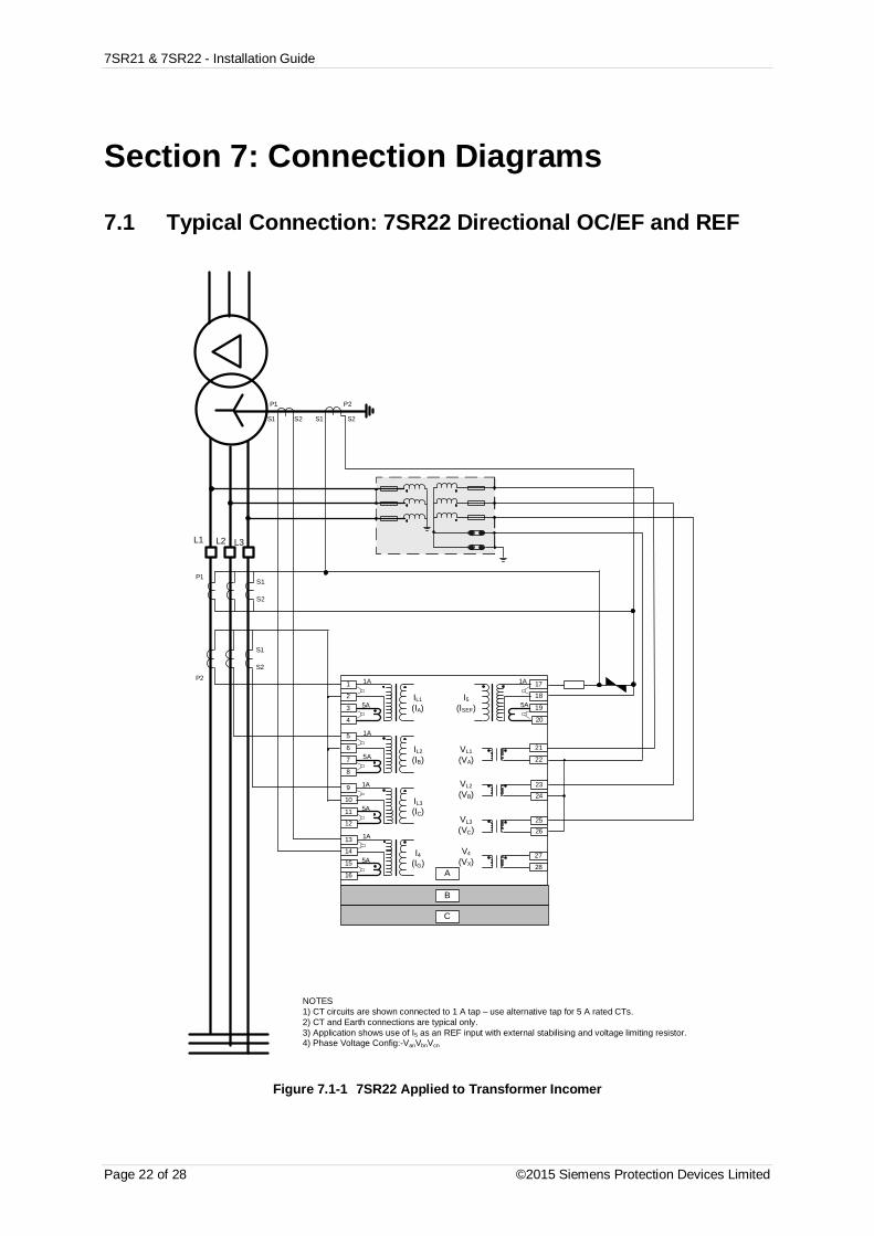
7SR21 & 7SR22 - Installation Guide
Page 22 of 28 ©2015 Siemens Protection Devices Limited
Section 7: Connection Diagrams
7.1 Typical Connection: 7SR22 Directional OC/EF and REF
IL1
(IA)
1
2
5
6
9
10
13
14
A
17
18
19
20
21
22
23
24
2526
27
28
1A
5A
1A
5A
1A
5A
1A
5A15
16
11
12
1A
5A3
4
7
8
B
C
S1
S2P2
L1 L2 L3
S1
S2
P1
V4
(VX)
VL3(VC)
VL2
(VB)
VL1
(VA)
NOTES1) CT circuits are shown connected to 1 A tap – use alternative tap for 5 A rated CTs.2) CT and Earth connections are typical only.3) Application shows use of I5 as an REF input with external stabilising and voltage limiting resistor.4) Phase Voltage Config:-VanVbnVcn
P2P1
S1 S2 S1 S2
IL2
(IB)
IL3(IC)
I4(IG)
I5(ISEF)
Figure 7.1-1 7SR22 Applied to Transformer Incomer
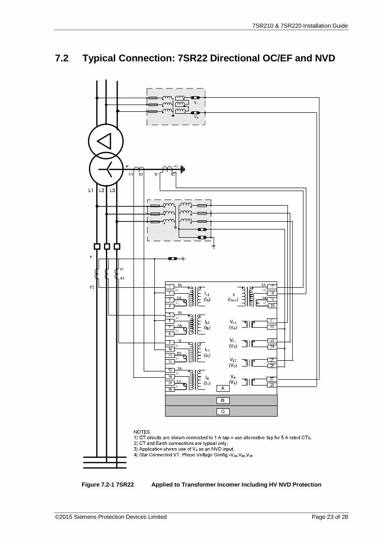
7SR210 & 7SR220 Installation Guide
©2015 Siemens Protection Devices Limited Page 23 of 28
7.2 Typical Connection: 7SR22 Directional OC/EF and NVD
Figure 7.2-1 7SR22 Applied to Transformer Incomer Including HV NVD Protection

7SR21 & 7SR22 - Installation Guide
Page 24 of 28 ©2015 Siemens Protection Devices Limited
7.3 Typical Connection: 7SR22 Directional OC/EF and NVD
S1
S2
P1
P2
L1 L2 L3
VL
VN
NOTES1) CT circuits are shown connected to 1 A tap – use alternative tap for 5 A rated CTs.2) CT and Earth connections are typical only.3) Application shows use of V4 as an NVD input.4) Star Connected VT: Phase Voltage Config:-Van,Vbn,Vcn
IL1
(IA)
1
2
5
6
9
10
13
14
A
17
18
19
20
21
22
23
24
25
26
27
28
1A
5A
1A
5A
1A
5A
1A
5A15
16
11
12
1A
5A3
4
7
8
B
C
V4
(VX)
VL3
(VC)
VL2
(VB)
VL1
(VA)IL2
(IB)
IL3
(IC)
I4(IG)
I5
(ISEF)
Figure 7.3-1 7SR22 Applied to Feeder Including NVD Protection

7SR210 & 7SR220 Installation Guide
©2015 Siemens Protection Devices Limited Page 25 of 28
7.4 Typical Connection: 7SR22 Directional OC/EF and NVD
VL
VN
L1 L2 L3
3Vo
S1
S2
P1
P2
IL1
(IA)
1
2
5
6
9
10
13
14
A
17
18
19
20
21
22
23
24
25
26
27
28
1A
5A
1A
5A
1A
5A
1A
5A15
16
11
12
1A
5A3
4
7
8
B
C
V4
(VX)
VL3
(VC)
VL2
(VB)
VL1
(VA)IL2
(IB)
IL3
(IC)
I4(IG)
I5(ISEF)
NOTES1) CT circuits are shown connected to 1 A tap – use alternative tap for 5 A rated CTs.2) CT and Earth connections are typical only.3) Voltage Config:-Vab, Vbc, 3V0
Figure 7.4-1 7SR22 Applied to Feeder

7SR21 & 7SR22 - Installation Guide
Page 26 of 28 ©2015 Siemens Protection Devices Limited
7.5 Typical Connection: 7SR22 Directional OC and EF
L1 L2 L3
A
C
B
S1
S2
P1
P2
IL1(IA)
1
2
5
6
9
10
13
14
A
17
18
19
20
21
22
23
24
25
26
27
28
1A
5A
1A
5A
1A
5A
1A
5A15
16
11
12
1A
5A3
4
7
8
B
C
V4(VX)
VL3(VC)
VL2(VB)
VL1(VA)
IL2(IB)
IL3(IC)
I4(IG)
I5(ISEF)
NOTES1) CT circuits are shown connected to 1 A tap – use alternative tap for 5 A rated CTs.2) CT and Earth connections are typical only.3) Vee Connected VT: Phase Voltage Config:-Va,Vb,Vc4) DEF elements must be NPS polarised (Vo polarising not applicable)
Figure 7.5-1 7SR22 Applied to Feeder - No Zero Sequence Voltage Source

7SR210 & 7SR220 Installation Guide
©2015 Siemens Protection Devices Limited Page 27 of 28
7.6 Typical Connection: 7SR22 Connected to VTs andCapacitor Cone Unit
L1 L2 L3
A
C
B
S1
S2
P1
P2
IL1
(IA)
1
2
5
6
9
10
13
14
A
17
18
19
20
21
22
23
24
25
26
27
28
1A
5A
1A
5A
1A
5A
1A
5A15
16
11
12
1A
5A3
4
7
8
B
C
V4
(VX)
VL3
(VC)
VL2
(VB)
VL1
(VA)IL2
(IB)
IL3
(IC)
I4(IG)
I5
(ISEF)
NOTES1) CT circuits are shown connected to 1 A tap – use alternative tap for 5 A rated CTs.2) CT and Earth connections are typical only.3) Vee Connected VT: Phase Voltage Config:-Va,Vb,Vc4) DEF elements must be NPS polarised (Vo polarising not applicable)5) V4 used for NVD input
CapacitorCones
AdaptorUnit
Figure 7.6-1 7SR22 Applied to Feeder with Capacitor Cones Fitted
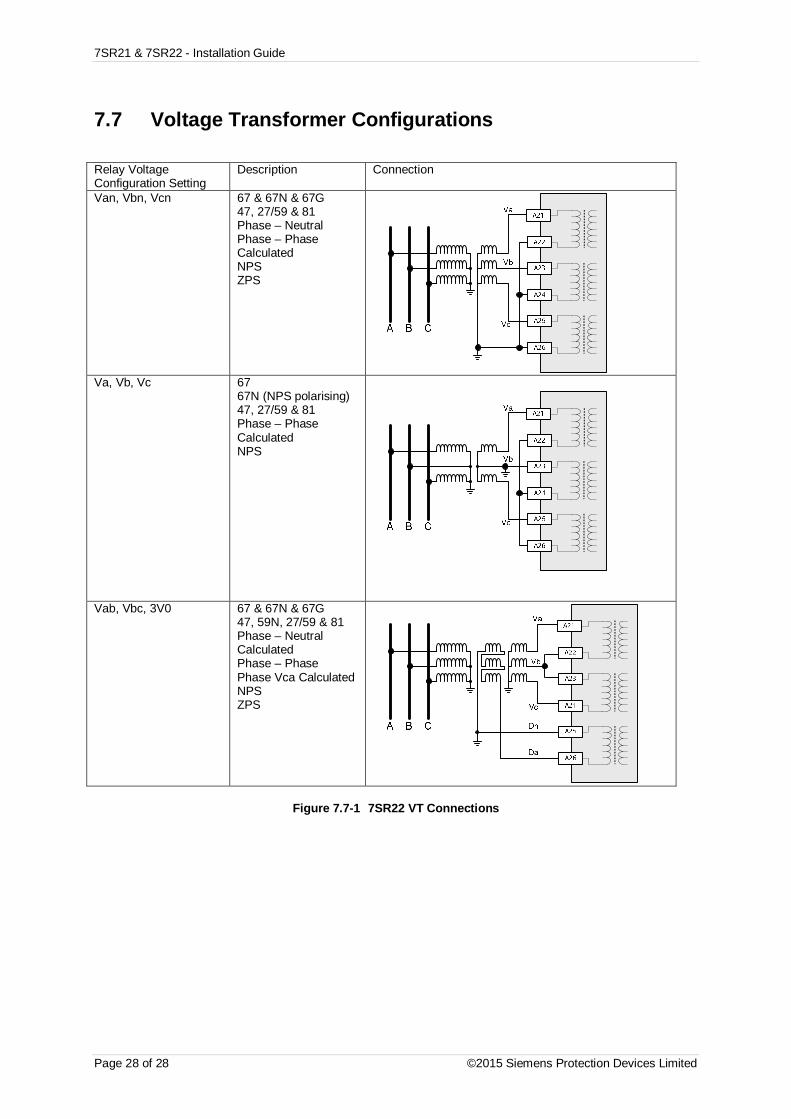
7SR21 & 7SR22 - Installation Guide
Page 28 of 28 ©2015 Siemens Protection Devices Limited
7.7 Voltage Transformer Configurations
Relay VoltageConfiguration Setting
Description Connection
Van, Vbn, Vcn 67 & 67N & 67G47, 27/59 & 81Phase – NeutralPhase – PhaseCalculatedNPSZPS
Va, Vb, Vc 6767N (NPS polarising)47, 27/59 & 81Phase – PhaseCalculatedNPS
Vab, Vbc, 3V0 67 & 67N & 67G47, 59N, 27/59 & 81Phase – NeutralCalculatedPhase – PhasePhase Vca CalculatedNPSZPS
Figure 7.7-1 7SR22 VT Connections

The copyright and other intellectual property rights in this document, and in any model or article produced from it(and including any registered or unregistered design rights) are the property of Siemens Protection DevicesLimited. No part of this document shall be reproduced or modified or stored in another form, in any data retrievalsystem, without the permission of Siemens Protection Devices Limited, nor shall any model or article bereproduced from this document unless Siemens Protection Devices Limited consent.
While the information and guidance given in this document is believed to be correct, no liability shall be acceptedfor any loss or damage caused by any error or omission, whether such error or omission is the result ofnegligence or any other cause. Any and all such liability is disclaimed.
© 2013 Siemens Protection Devices Limited
7SR21 Non-Directional Relay
7SR22 Directional Relay
Commissioning & MaintenanceGuide

7SR210 & 7SR220 Commissioning & Maintenance Guide
Page 2 of 74 © 2013 Siemens Protection Devices Limited
Document Release History
This document is issue 2015/06.
2011/05 First issue
2013/01 Typographical revisions and added data. Updated in line with software release.
2014/06 Typographical revisions and added data. Updated in line with software release.
2015/06 Typographical revisions, drawing amendments and added data. Updated in line withsoftware release.
Software Revision History2011/05 2435H85008R7a-7a (7SR210)
2435H85009R7a-7a (7SR220)
First Release
2013/01 2435H85008R7c-7b (7SR210)
2435H85009R7c-7b (7SR220)
Introduced journaling file system.Added 61850 logical nodes for CB Counters, metering, 50BF,46BC, 81HBL2 and line check.Added Line Check on non-AR devices.Added 74CCS Close Circuit Supervision.
2014/06 2435H85008R7f-7d (7SR210)
2435H85009R7f-7d (7SR220)
Added Fault Locator feature and Check Sync feature.Fault data transmitted over 103.Additional communications data, control features, meters.
2015/06 2435H85008R8a-7f (7SR210)
2435H85009R8a-7f (7SR220)
Added Power Factor Meters, Load Blinding feature, Arc FlashDetector. Over current TM Setting Range extended.

7SR210 & 7SR220 Commissioning & Maintenance Guide
© 2013 Siemens Protection Devices Limited Page 3 of 74
Contents
Document Release History ............................................................................................................... 2Software Revision History ................................................................................................................ 2Contents ............................................................................................................................................ 3Section 1: Common Functions ......................................................................................................... 6
1.1 Overview .............................................................................................................................. 61.2 Before Testing ...................................................................................................................... 6
1.2.1 Safety ...................................................................................................................... 61.2.2 Sequence of Tests ................................................................................................... 61.2.3 Test Equipment........................................................................................................ 71.2.4 Precautions.............................................................................................................. 71.2.5 Applying Settings ..................................................................................................... 7
1.3 Tests .................................................................................................................................... 91.3.1 Inspection ................................................................................................................ 91.3.2 Secondary Injection Tests ........................................................................................ 91.3.3 Primary Injection Tests............................................................................................. 91.3.4 Putting into Service .................................................................................................. 9
1.4 AC Energising Quantities ................................................................................................... 101.5 Binary Inputs ...................................................................................................................... 111.6 Binary Outputs ................................................................................................................... 121.7 Relay Case Shorting Contacts ............................................................................................ 13
Section 2: Protection Functions ..................................................................................................... 142.1 Phase Directional Polarity Check ........................................................................................ 15
2.1.1 2 out of 3 logic ....................................................................................................... 162.2 Phase Overcurrent (67/50,67/51) ....................................................................................... 17
2.2.1 Definite Time Overcurrent. (50) .............................................................................. 182.2.2 Inverse Time Overcurrent. (51) .............................................................................. 18
2.3 Voltage Controlled Overcurrent (51V) ................................................................................. 202.4 Cold Load (51c).................................................................................................................. 22
2.4.1 Inverse Time Overcurrent. (51C) ............................................................................ 232.5 Directional Earth Fault Polarity Check (67N) ....................................................................... 252.6 Derived Earth Fault (67/50N, 67/51N) ................................................................................. 26
2.6.1 Directional Polarity ................................................................................................. 272.6.2 Definite Time Overcurrent..(50N)............................................................................ 272.6.3 Inverse Time Overcurrent. (51N) ............................................................................ 27
2.7 Measured Earth fault (67/50G,67/51G) ............................................................................... 302.7.1 Directional Polarity ................................................................................................. 312.7.2 Definite Time Overcurrent..(67/50G)....................................................................... 312.7.3 Inverse Time Overcurrent. (67/51G) ....................................................................... 31
2.8 Sensitive Earth fault (67/50S,67/51S) ................................................................................. 342.8.1 Directional Polarity ................................................................................................. 352.8.2 Definite Time Overcurrent. (50SEF) ....................................................................... 352.8.3 Inverse Time Overcurrent. (51SEF) ........................................................................ 35
2.9 Restricted Earth fault. (64H) ............................................................................................... 382.10 Negative Phase Sequence Overcurrent (46NPS)................................................................ 40
2.10.1 Definite Time NPS Overcurrent. (46DT) ................................................................. 412.10.2 Inverse Time NPS Overcurrent. (46IT) ................................................................... 41
2.11 Undercurrent. (37) .............................................................................................................. 43

7SR210 & 7SR220 Commissioning & Maintenance Guide
Page 4 of 74 © 2013 Siemens Protection Devices Limited
2.12 Thermal Overload (49) ....................................................................................................... 452.13 Over/Under Voltage............................................................................................................ 47
2.13.1 Phase Under/Over Voltage. (27/59) ....................................................................... 472.13.2 Undervoltage Guard (27/59UVG) ........................................................................... 492.13.3 Vx Under/Over Voltage. (Vx 27/59) ........................................................................ 502.13.4 NPS Overvoltage (47) ............................................................................................ 522.13.5 Neutral Overvoltage (59N) ..................................................................................... 542.13.6 Definite Time (59NDT) ........................................................................................... 542.13.7 Inverse Time (59NIT) ............................................................................................. 552.13.8 Under/Over Frequency (81) ................................................................................... 56
Section 3: Supervision Functions .................................................................................................. 583.1 CB Fail. (50BF) .................................................................................................................. 583.2 Voltage Transformer Supervision. (60VTS) ......................................................................... 60
3.2.1 1 or 2 Phase VT fail ............................................................................................... 613.2.2 3 Phase VT fail ...................................................................................................... 61
3.3 Current Transformer Supervision. (60CTS) ......................................................................... 623.3.1 Element Blocking ................................................................................................... 63
3.4 Broken Conductor. (46BC) ................................................................................................. 643.4.1 Element Blocking ................................................................................................... 65
3.5 Load Blinder (21)................................................................................................................ 663.5.1 Determining Load Blinder Regions (21LB) .............................................................. 683.5.2 Determining Trip Level ........................................................................................... 69
3.6 Trip Circuit Supervision. (74TCS) ....................................................................................... 703.7 Magnetising Inrush Detector. (81HBL) ................................................................................ 71
Section 4: Control & Logic Functions ............................................................................................ 724.1 Autoreclose (79) ................................................................................................................. 724.2 Quick Logic ........................................................................................................................ 72
Section 5: Testing and Maintenance .............................................................................................. 735.1 Periodic Tests .................................................................................................................... 735.2 Maintenance ...................................................................................................................... 735.3 Troubleshooting ................................................................................................................. 74

7SR210 & 7SR220 Commissioning & Maintenance Guide
© 2013 Siemens Protection Devices Limited Page 5 of 74
List of FiguresFigure 2.1-1 Directional Phase Fault Boundary System Angles ................................................... 16Figure 2.2-1 Phase Overcurrent ..................................................................................................... 17Figure 2.3-1 Voltage Controlled Overcurrent ................................................................................. 20Figure 2.4-1 Cold Load ................................................................................................................... 22Figure 2.4-2 Cold Load Logic diagram ........................................................................................... 23Figure 2.5-1 Directional Earth Fault Boundary System Angles .................................................... 25Figure 2.6-1 Derived Earth Fault .................................................................................................... 26Figure 2.7-1 Measured Earth Fault ................................................................................................. 30Figure 2.8-1 Sensitive Earth Fault .................................................................................................. 34Figure 2.9-1 Restricted Earth Fault ................................................................................................ 38Figure 2.10-1 Negative Phase Sequence Overcurrent .............................................................. 40Figure 2.11-1 Undercurrent ........................................................................................................ 43Figure 2.12-1 Thermal Overload ................................................................................................ 45Figure 2.13-1 Phase Under/Over Voltage .................................................................................. 47Figure 2.13-2 Vx Under/Over Voltage ........................................................................................ 50Figure 2.13-3 NPS Overvoltage .................................................................................................. 52Figure 2.13-4 Neutral Overvoltage ............................................................................................. 54Figure 2.13-5 Under/Over Frequency ........................................................................................ 56Figure 3.1-1 CB Fail ........................................................................................................................ 58Figure 3.2-1 Voltage Transformer Supervision.............................................................................. 60Figure 3.3-1 Current Transformer Supervision.............................................................................. 62Figure 3.4-1 Broken Conductor ...................................................................................................... 64Figure 3.5-1 Load Blinder (21) ........................................................................................................ 66Figure 3.5-2 Load Blinder (21) Boundary Points ........................................................................... 67Figure 3.6-1 Trip Circuit Supervision ............................................................................................. 70Figure 3.7-1 Magnetising Inrush Detector ..................................................................................... 71

7SR210 & 7SR220 Commissioning & Maintenance Guide
Page 6 of 74 © 2013 Siemens Protection Devices Limited
Section 1: Common Functions1.1 OverviewCommissioning tests are carried out to prove: -
a) Equipment has not been damaged in transit.
b) Equipment has been correctly connected and installed.
c) Prove characteristics of the protection and settings which are based on calculations.
d) Confirm that settings have been correctly applied.
e) To obtain a set of test results for future reference.
1.2 Before Testing
1.2.1 SafetyThe commissioning and maintenance of this equipment should only be carried out by skilled personnel trained inprotective relay maintenance and capable of observing all the safety precautions and regulations appropriate tothis type of equipment and also the associated primary plant.
Ensure that all test equipment and leads have been correctly maintained and are in good condition. It isrecommended that all power supplies to test equipment be connected via a Residual Current Device (RCD),which should be located as close to the supply source as possible.
The choice of test instrument and test leads must be appropriate to the application. Fused instrument leadsshould be used when measurements of power sources are involved, since the selection of an inappropriate rangeon a multi-range instrument could lead to a dangerous flashover. Fused test leads should not be used where themeasurement of a current transformer (C.T.) secondary current is involved, the failure or blowing of an instrumentfuse or the operation of an instrument cut-out could cause the secondary winding of the C.T. to become an opencircuit.
Open circuit secondary windings on energised current transformers are a hazard that can produce high voltagesdangerous to personnel and damaging to equipment, test procedures must be devised so as to eliminate this risk.
1.2.2 Sequence of TestsIf other equipment is to be tested at the same time, then such testing must be co-ordinated to avoid danger topersonnel and equipment.
When cabling and wiring is complete, a comprehensive check of all terminations for tightness and compliancewith the approved diagrams must be carried out. This can then be followed by the insulation resistance tests,which if satisfactory allows the wiring to be energised by either the appropriate supply or test supplies.
When primary injection tests are completed satisfactorily, all remaining systems can be functionally tested beforethe primary circuit is energised. Some circuits may require further tests before being put on load.
Protection relay testing will require access to the protection system wiring diagrams; relay configurationinformation and protection settings. The following sequence of tests is loosely based on the arrangement of therelay menu structure. A test log based on the actual tests completed should be recorded for each relay tested.
The ‘Description of Operation’ section of this manual provides detailed information regarding the operation ofeach function of the relay.

7SR210 & 7SR220 Commissioning & Maintenance Guide
© 2013 Siemens Protection Devices Limited Page 7 of 74
1.2.3 Test EquipmentRequired test equipment is: -
1. Secondary injection equipment with integral time interval meter2. Primary injection equipment3. A d.c. supply with nominal voltage within the working range of the relay's d.c. auxiliary supply rating4. A d.c. supply with nominal voltage within the working range of the relay’s d.c. binary input rating5. Other equipment as appropriate to the protection being commissioned – this will be specified in the
product specific documentation.
The secondary injection equipment should be appropriate to the protection functions to be tested. Additionalequipment for general tests and for testing the communications channel is:
Portable PC with appropriate interface equipment: -6. Portable PC with appropriate interface equipment.7. Printer to operate from the above PC (Optional).
Use of PC to facilitate testing
The functions of Reydisp Evolution (see Settings Guide) can be used during the commissioning tests to assistwith test procedures or to provide documentation recording the test and test parameters. One method is to clearboth the waveform and event records before each test is started, then, after the test upload from the relay thesettings, events and waveform files generated as a result of application of the test. These can then be saved off toretain a comprehensive record of that test.
Relay settings files can be prepared on the PC (offline) or on the relay before testing commences. These settingsshould be saved for reference and compared with the settings at the end of testing to check that errors have notbeen introduced during testing and that any temporary changes to settings to suit the test process are returned tothe required service state.
A copy of the Relay Settings as a Rich Text Format (.rtf) file suitable for printing or for record purposes can beproduced from Reydisp as follows. From the File menu select Save As, change the file type to ExportDefault/Actual Setting (.RTF) and input a suitable filename.
When testing is completed the event and waveform records should be cleared and the settings file checked toensure that the required in-service settings are being applied.
1.2.4 PrecautionsBefore electrical testing commences the equipment should be isolated from the current and voltage transformers.The current transformers should be short-circuited in line with the local site procedure. The tripping and alarmcircuits should also be isolated where practical. The provision and use of secondary injection test sockets on thepanel simplifies the isolation and test procedure.
Ensure that the correct auxiliary supply voltage and polarity is applied. See the relevant scheme diagrams for therelay connections.
Check that the nominal secondary current rating of the current and voltage transformers has been correctly set inthe System Config. menu of the relay.
1.2.5 Applying SettingsThe relay settings for the particular application should be applied before any secondary testing occurs. If they arenot available then the relay has default settings that can be used for pre-commissioning tests.
Note that the tripping and alarm contacts for any function must be programmed correctly before any scheme testsare carried out.
Relays feature multiple settings groups, only one of which is active at a time. In applications where more than onesettings group is to be used it may be necessary to test the relay in more than one configuration.
Note. One group may be used as a ‘Test’ group to hold test-only settings that can be used for regularmaintenance testing, eliminating the need for the Test Engineer to interfere with the actual in-service settings inthe normally active group. This Test group may also be used for functional testing where it is necessary to disableor change settings to facilitate testing.
When using settings groups it is important to remember that the relay need not necessarily be operatingaccording to the settings that are currently being displayed.

7SR210 & 7SR220 Commissioning & Maintenance Guide
Page 8 of 74 © 2013 Siemens Protection Devices Limited
There is an ‘active settings group’ on which the relay operates and an ‘edit/view settings group’ which is visible onthe display and which can be altered. This allows the settings in one group to be altered from the relay fasciawhile the protection continues to operate on a different unaffected group. The ‘Active Settings Group’ and the ‘EditSettings Group’ are selected in the ‘System Configuration Menu’.
The currently Active Group and the group currently Viewed are shown at the top of the display in the Settingsdisplay screen. If the View Group is not shown at the top of the display, this indicates that the setting is commonto all groups. CT/VT ratio, I/O mapping and other settings which are directly related to hardware are common toall groups.
If the relay is allowed to trip during testing then the instruments display will be interrupted and replaced by the‘Trip Alert’ screen which displays fault data information. If this normal operation interferes with testing then thisfunction can be temporarily disabled for the duration of testing by use of the Trip Alert Enabled/Disabled setting inthe System Config Menu.
After applying a settings change to the relay, which may involve a change to the indication and output contacts,the TEST/RESET key should be pressed to ensure any existing indication and output is correctly cleared.

7SR210 & 7SR220 Commissioning & Maintenance Guide
© 2013 Siemens Protection Devices Limited Page 9 of 74
1.3 Tests
1.3.1 InspectionEnsure that all connections are tight and correct to the relay wiring diagram and the scheme diagram. Record anydeviations. Check that the relay is correctly programmed and that it is fully inserted into the case. Refer to‘Settings Guide’ for information on programming the relay.
1.3.2 Secondary Injection TestsSelect the required relay configuration and settings for the application.
Isolate the auxiliary D.C. supplies for alarm and tripping from the relay and remove the trip and inter-trip links.
Carry out injection tests for each relay function, as described in this document
For all high current tests it must be ensured that the test equipment has the required rating and stability and thatthe relay is not stressed beyond its thermal limit.
1.3.3 Primary Injection TestsPrimary injection tests are essential to check the ratio and polarity of the transformers as well as the secondarywiring.
Note. If the current transformers associated with the protection are located in power transformer bushings it maynot be possible to apply test connections between the current transformer and the power transformer windings.Primary injection is needed, however, to verify the polarity of the CTs. In these circumstances primary currentmust be injected through the associated power transformer winding. It may be necessary to short circuit anotherwinding in order to allow current to flow. During these primary injection tests the injected current is likely to besmall due to the impedance of the transformer.
1.3.4 Putting into ServiceAfter tests have been performed satisfactorily the relay should be put back into service as follows:-
Remove all test connections.
Replace all secondary circuit fuses and links, or close m.c.b.
Ensure the Protection Healthy LED is on, steady, and that all LED indications are correct. If necessary pressCANCEL until the Relay Identifier screen is displayed, then press TEST/RESET to reset the indication LEDs.
The relay meters should be checked in Instruments Mode with the relay on load.
The relay settings should be downloaded to a computer and a printout of the settings produced. The installedsettings should then be compared against the required settings supplied before testing began. Automated settingcomparison can be carried out by Reydisp using the Compare Settings Groups function in the Edit menu. Anymodified settings will be clerly highlighted.

7SR210 & 7SR220 Commissioning & Maintenance Guide
Page 10 of 74 © 2013 Siemens Protection Devices Limited
1.4 AC Energising QuantitiesVoltage and current measurement for each input channel is displayed in the Instrumentation Mode sub-menus,each input should be checked for correct connection and measurement accuracy by single phase secondaryinjection at nominal levels. Ensure that the correct instrument displays the applied signal within limits of thePerformance Specification.
Applied Current Applied Voltage
IA IB IC IG ISEF VA/VAB VB/VBC VC/VCB VX
Secondary
Primary
Apply 3P balanced Current and Voltage at nominal levels and ensure that the measured Zero Phase Sequenceand Negative Phase Sequence quantities are approximately zero.
ZPS NPS
Voltage
Current

7SR210 & 7SR220 Commissioning & Maintenance Guide
© 2013 Siemens Protection Devices Limited Page 11 of 74
1.5 Binary InputsThe operation of the binary input(s) can be monitored on the ‘Binary Input Meters’ display shown in ‘InstrumentsMode’. Apply the required supply voltage onto each binary input in turn and check for correct operation.Depending on the application, each binary input may be programmed to perform a specific function; each binaryshould be checked to prove that its mapping and functionality is as set as part of the Scheme Operation tests.
Where the pick-up timers associated with a binary input are set these delays should be checked either as part ofthe scheme logic or individually. To check a binary pick-up time delay, temporarily map the binary to an outputrelay that has a normally open contact. This can be achieved in the Output Matrix sub-menu by utilising the BI nOperated settings. Use an external timer to measure the interval between binary energisation and closure of theoutput contacts. Similarly, to measure the drop-off delay, map to an output relay that has a normally closedcontact, time the interval between binary de-energisation and closure of the output contacts.
Note. The time measured will include an additional delay, typically less than 20 ms, due to the response time ofthe binary input hardware, software processing time and the operate time of the output relay.
BI Tested DODelay Measured PU
Delay Measured Notes (method of initiation)
1
2
3
4
5
6
7
8
9
10
11
12
13
14
15
16
17
18
19
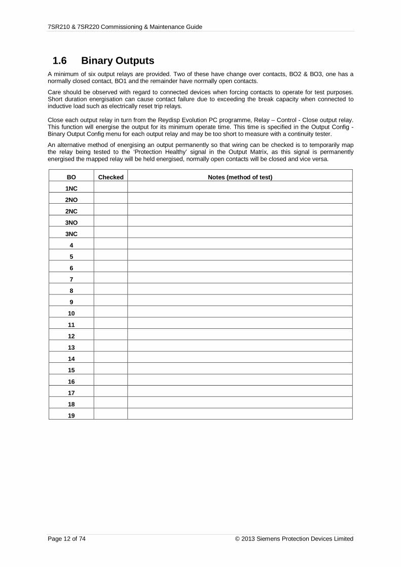
7SR210 & 7SR220 Commissioning & Maintenance Guide
Page 12 of 74 © 2013 Siemens Protection Devices Limited
1.6 Binary OutputsA minimum of six output relays are provided. Two of these have change over contacts, BO2 & BO3, one has anormally closed contact, BO1 and the remainder have normally open contacts.
Care should be observed with regard to connected devices when forcing contacts to operate for test purposes.Short duration energisation can cause contact failure due to exceeding the break capacity when connected toinductive load such as electrically reset trip relays.
Close each output relay in turn from the Reydisp Evolution PC programme, Relay – Control - Close output relay.This function will energise the output for its minimum operate time. This time is specified in the Output Config -Binary Output Config menu for each output relay and may be too short to measure with a continuity tester.
An alternative method of energising an output permanently so that wiring can be checked is to temporarily mapthe relay being tested to the ‘Protection Healthy’ signal in the Output Matrix, as this signal is permanentlyenergised the mapped relay will be held energised, normally open contacts will be closed and vice versa.
BO Checked Notes (method of test)
1NC
2NO
2NC
3NO
3NC
4
5
6
7
8
9
10
11
12
13
14
15
16
17
18
19

7SR210 & 7SR220 Commissioning & Maintenance Guide
© 2013 Siemens Protection Devices Limited Page 13 of 74
1.7 Relay Case Shorting ContactsCT inputs and terminals B25-B26 (Relay Withdrawn Alarm) are fitted with case mounted shorting contacts whichprovide a closed contact when the relay is withdrawn from the case. The operation of these contacts should bechecked.
CT Shorting contacts checked
Relay Withdrawn Alarm Checked

7SR210 & 7SR220 Commissioning & Maintenance Guide
Page 14 of 74 © 2013 Siemens Protection Devices Limited
Section 2: Protection FunctionsThis section details the procedures for testing each protection function of the 7SR21 & 7SR22 relays. These testsare carried out to verify the accuracy of the protection pick-ups and time delays at setting and to confirm correctoperation of any associated input and output functionality.
The exact model type must be checked to confirm the functions available in each type.
Guidance for calculating test input quantities is given in the relevant test description where required. In manycases it may be necessary to disable some functions during the testing of other functions, this prevents anyambiguity caused by the operation of multiple functions from one set of input quantities. The ‘Function Config’Menu provides a convenient high level point at which all elements of a particular function can beEnabled/Disabled to suit testing. The ‘Config’ tab in ‘Reydisp Evolution’ can be used to ‘Enable/Disable’ individualelements. Note that this screen disables functions by applying setting changes to the relay and that any changesmust be sent to the relay to take effect and settings must be returned to their correct value after testing.
The table below indicates functions where function conflicts may occur during testing, consideration should begiven to disabling functions to avoid interference.
Any LED can be assigned to be a General Pickup LED in the Output Matrix menu and can be used to assessoperation of functions during testing if other functions are disabled or if the setting allocating General Pickup istemporarily modified.
Voltage inputs may not be required for testing of non-directional Overcurrent elements but it may beadvantageous to apply balanced 3 phase nominal rated voltage to the VT inputs during testing to avoidinadvertent operation of other functions. Particular care should be taken when testing overcurrent functions thatthe thermal rating of the current inputs is not exceeded.
Function
Under Test
Phas
eO
verc
urre
nt
Volta
geC
ontO
/C
Col
dLo
ad
Der
ived
E/F
Mea
sure
dE/
F
Sens
itive
E/F
Res
tric
ted
E/F
NPS
Ove
rcur
rent
Und
ercu
rren
t
Ther
mal
Phas
eU
/Ovo
ltage
NPS
Ove
rvol
tage
U/O
Freq
uenc
y
CB
Fail
VTSu
perv
isio
n
CT
supe
rvis
ion
Bro
ken
Con
duct
or
Trip
cct
Supe
rvis
ion
Inru
shD
etec
tor
PhaseOvercurrent
O O O O O O O
Voltage ContO/C
O O O O O O O
Cold Load O O O O O O O
Derived E/F O O O O O O O
Measured E/F O O O O
Sensitive E/F O
Restricted E/F O
NPS Overcurrent O O O O O O O
Undercurrent O O O
Thermal O O O O
Phase U/Ovoltage
O O O
NPSOvervoltage
O O O
U/O Frequency O O
CB Fail O O O O O O O O
VT Supervision O O
CT supervision O O
BrokenConductor
O O O OOTrip cct
SupervisionInrush Detector

7SR210 & 7SR220 Commissioning & Maintenance Guide
© 2013 Siemens Protection Devices Limited Page 15 of 74
It should be considered that where several overlapping elements are used simultaneously, the overall protectionoperate time may be dependent on the operation of different individual elements at the various levels of appliedcurrent or voltage. The resulting composite characteristic may be tested by enabling all of the relevant applicableelements or the element operations can be separated or disabled and tested individually.
All relay settings should be checked before testing begins. It is recommended that the relay settings are extractedfrom the relay using Reydisp Evolution software and a copy of these settings is stored for reference during andafter testing. It may be necessary to disable some protection functions during the testing of other functions toallow unambiguous results to be obtained.
Care must be taken to reset or re-enable any settings that have been temporarily altered during the testing beforethe relay can be put into service. At the end of testing the relay settings should be compared to the file extractedat the start to ensure that errors have not been introduced.
2.1 Phase Directional Polarity CheckIf the relay has Directional Overcurrent elements, the common direction polarising can be checked independentlyfrom the individual overcurrent elements and their settings.
In the INSTRUMENTS MODE display, indication is provided in the DIRECTIONAL METERS menu which displayscurrent direction under P/F Dir as forward or reverse based on the output states of the directional elements, i.e.whether they see forward current, reverse current or neither for each pole with respect to the 67 Char Anglesetting in the Phase Overcurrent menu. This display and the equivalent Measured and Calculated Earth Faultdirection meters can be used as an aid to commissioning testing.
1. Check the direction of each pole in turn by connecting to the appropriate terminals. The table below showsthe polarising quantity for each pole.
Connections for Directional Polarity
Overcurrent pole Polarising voltagePhase A VBC
Phase B VCA
Phase C VAB
2. Inject single phase rated current and apply single phase-phase rated voltage at the Char Angle (MTA) phaseangle setting, to each phase in turn. For each pole, monitor the directional display in the instrument menuand check that indication of forward current (FWD) is displayed. To achieve the required forwardCharacteristic Angle, the phase angle of the current should be greater than that of the polarising voltage bythe angle setting.
3. Repeat all of the above with the current connections reversed. Indication should now be given of reverse(REV) current flow.
Phase A B C
Forward FWD FWD FWD
Reverse REV REV REV
Apply balanced 3 phase rated voltage and current with Vbc voltage as a 0deg reference and Ia at thecharacteristic angle. Increase current phase angle until the ‘Fwd’ indication is extinguished. Record this anglein the table below (Forward lead DO). Continue to increase/decrease the angle until the instrument reads‘Rev’. Record the angle (Reverse lead PU). Reduce the current angle until the ’Rev’ extinguishes (Reverselead DO). and the ‘Fwd’ subsequently returns (Forward lead PU), recording the angles. Repeat the abovetests, starting from the Characteristic Angle, but reducing the current phase angle to record the directionalboundaries in the opposite (lag) direction. The recorded angle should be the angle at which the phase currentleads the phase-phase polarising voltage. This measurement is greatly simplified if the polarising referencevoltage is set to 0deg and the current phase angle is measured with respect to this reference.
Alternatively, the instrument can be checked at the 4 points marked a,b,c & d on Figure 2-1 only.

7SR210 & 7SR220 Commissioning & Maintenance Guide
Page 16 of 74 © 2013 Siemens Protection Devices Limited
VC VB
VA
IAWith balanced 3-phase system quantities:
Adjust the phase angle of the currentsrelative to the voltages:
Verify directional pick-up and drop off atpoints A, B, C and D
Alternatively,
Verify correct directional indication at pointsa, b, c and d (C.A +750, +950, -750, -950)
A
B
D
C
a
d
b
c
FWD
REV
+600
+300
00
+2700
+1800
+2100
+2400
+900
VBC
Forward Reverse
Lag (point C) Lead (point A) Lead(point B) Lag (point D)
Pick-up Drop-off Pick-up Drop-off Pick-up Drop-off Pick-up Drop-off
MTA MTA-85 MTA+85 MTA-85 MTA-85
Phase A
Phase B
Phase C
Figure 2.1-1 Directional Phase Fault Boundary System Angles
4. With the instrument reading ‘Fwd’ or ‘Rev’, reduce the voltage until the element resets. Record theminimum phase-phase operate voltage.
Minimum Voltage Setting Measured
2.1.1 2 out of 3 logic
Ensure that at least 1 Phase Overcurrent element is set to Directional. Apply balanced nominal voltage. Applycurrent at a level above on phase A only at the characteristic angle for forward operation, normally 45º lagging.Ensure no Directional Phase Overcurrent element operation occurs. Note that non-directional Phase Overcurrentand Non-direction Earth Fault elements may operate unless disabled.Repeat the test with Phase A current as above but also with equal current in the B phase at 180º to that in the Aphase.
1 phase current 2 phase currentNo 50/51-n Operation 50/51-n operation

7SR210 & 7SR220 Commissioning & Maintenance Guide
© 2013 Siemens Protection Devices Limited Page 17 of 74
2.2 Phase Overcurrent (67/50,67/51)7SR22
46BC
46NPS(x2)
37(x2) 49 50
BF
VL1
(VA)
VL2
(VB)
VL3
(VC)
V4
(VX)
IL1
(IA)
81HBL
2
37(x2) 49 50
BFIL2
(IB)
81HBL
2
37(x2) 49 50
BFIL3
(IC)
81HBL
2
60CTS
I4(IG)
I5(ISEF)
74TCS
NOTE: The use of somefunctions are mutually exclusive
67/50
(x4)
67/51
(x4)
67/50N(x4)
67/50
(x4)
67/50
(x4)
67/51
(x4)
67/51
(x4)
67/51N(x4)
67/50G(x4)
67/51G(x4)
67/50S(x4)
67/51S(x4)
64H
2759
2759
(x4)
2759
(x4)
2759
(x4)
47(x2)
81(x6)
79 Optional
59N(x2)
81HBL2N
60VTS
51V
51V
51V
37G(x2)
37S(x2)
51c
60CTS-
I
60CTS-
I
60CTS-
I
37 50BF
37 50BF
25
50ADF
50ADF
50ADF
51c
51c
51c
Figure 2.2-1 Phase Overcurrent
Voltage Inputs: VL1 (VA), VL2 (VB), VL3 (VC) for directional elements.
Current Inputs: IL1 (IA), IL2 (IB), IL3 (IC),
Disable: 51V, 51c, 46, 49, 50BF, 79
Map Pickup LED: 51-n/50-n - Self Reset
Other protection functions may overlap with these functions during testing, it may be useful to disable somefunctions to avoid ambiguity. It should be particularly noted that if the function is enabled, the 51C Cold Loadsettings may modify the normal 50-n and 51-n settings if the CB is open during testing.
Voltage inputs may not be required for this function if the Phase Overcurrent functions are not directional but itmay be advantageous to apply balanced 3 phase nominal rated voltage to the VT inputs during testing to avoidinadvertent operation of other functions. Particular care should be taken when testing overcurrent functions thatthe thermal rating of the current inputs is not exceeded.

7SR210 & 7SR220 Commissioning & Maintenance Guide
Page 18 of 74 © 2013 Siemens Protection Devices Limited
2.2.1 Definite Time Overcurrent. (50)If DTL setting is small, gradually increase current until element operates.
If DTL is large apply 0.9x setting, check for no operation, apply 1.1x setting, and check operation.
Apply 2x setting current if possible and record operating time.
Phase Dir. Is(Amps)
DTL(sec)
P.U. CurrentAmps Tol Operate Time
2 x Is TolIL1(IA)
IL2(IB)IL3(IC)
Check correct indication, trip output, alarm contacts, waveform record.
2.2.2 Inverse Time Overcurrent. (51)It will be advantageous to map the function being tested to temporarily drive the relevant Pickup output in thePickup Config sub-menu in the Output Config menu as this will allow the Pick-up led to operate for the function.
Gradually increase current until Pickup LED operates.
Apply 2x setting current and record operating time,
Apply 5x setting current and record operating time.
Compare to calculated values for operating times
Gradually reduce current until the element drops off and record the level.
P.U.D.O.
&TIMINGTESTS
Ph. Dir Char.Curve
Is(A) TM
Operate Current Operate TimeP.U.
(Amps)D.O.
(Amps) Tol 2 x Is(sec)
5 x Is(sec) Tol
IL1(IA)IL2(IB)
IL3(IC)
Calculated Timing values in seconds for TM =1.0Curve 2 xIs 5 xIsIEC-NI 10.03 4.28IEC-VI 13.50 3.38IEC-EI 26.67 3.33IEC-LTI 120.00 30.00ANSI-MI 3.80 1.69ANSI-VI 7.03 1.31ANSI-EI 9.52 1.30
Note that the operate time may be subject to the Minimum op time setting for the element and/or may have aFollower DTL applied.

7SR210 & 7SR220 Commissioning & Maintenance Guide
© 2013 Siemens Protection Devices Limited Page 19 of 74
1.1.1.1 Element Blocking
The Phase Overcurrent elements can be blocked by Binary Input Inhibit, VT Supervision and Inrush Detectoroperation, as well as 79 Autoreclose settings for Inst/Delayed. The Characteristic can be modified by Cold Load(51-n only) and Voltage Controlled Overcurrent and can be made non-directional by VT Supervision. Thisfunctionality should be checked.
Element BI Inhibits VTS action Inrush Detector 79 Autoreclose
51-1
51-2
51-3
51-4
50-1
50-2
50-3
50-4
.
2.1.1.1 ANSI Reset
If the element is configured as an ANSI characteristic, it may have an ANSI (decaying) reset delay applied. IfANSI reset is selected for an IEC characteristic element, the reset will be instantaneous.
ANSI reset times from operated condition to fully reset are as follows for zero applied current and Time multiplier(TM) = 1.0. The reset curve characteristic type and TM is defined by the operating characteristic.
Curve Fully operated to reset with Zero current applied & TM=1 (secs)ANSI-MI 4.85ANSI-VI 21.6ANSI-EI 29.1
Apply current in the following sequence, a) 2x setting for a time to ensure element operation, b) Zero current forthe reset time above (xTM), c) 2x setting for a time to ensure element operation. Check that the second operation(c) is similar to the first (a) and in line with the expected operate time for the element at this current level.
Repeat the test with the reset time (b) reduced to 50% of the previous value. Ensure that the second operate time(c) is 50% of the first (a) operate time.
Check correct indication, trip output, alarm contacts, waveform record.
Operate time(expected)
Reset time(calculated)
Operate time(measured)
50% ResetTime
(calculated)
50% operatetime
(calculated)
50% operatetime
(measured)First test (c) Second Test (c)
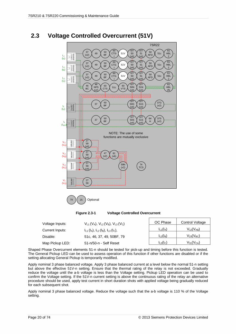
7SR210 & 7SR220 Commissioning & Maintenance Guide
Page 20 of 74 © 2013 Siemens Protection Devices Limited
2.3 Voltage Controlled Overcurrent (51V)7SR22
46BC
46NPS(x2)
37(x2) 49 50
BF
VL1
(VA)
VL2
(VB)
VL3
(VC)
V4
(VX)
IL1
(IA)
81HBL
2
37(x2) 49 50
BFIL2
(IB)
81HBL
2
37(x2) 49 50
BFIL3
(IC)
81HBL
2
60CTS
I4(IG)
I5(ISEF)
74TCS
NOTE: The use of somefunctions are mutually exclusive
67/50
(x4)
67/51
(x4)
67/50N(x4)
67/50
(x4)
67/50
(x4)
67/51
(x4)
67/51
(x4)
67/51N(x4)
67/50G(x4)
67/51G(x4)
67/50S(x4)
67/51S(x4)
64H
2759
2759
(x4)
2759
(x4)
2759
(x4)
47(x2)
81(x6)
79 Optional
59N(x2)
81HBL2N
60VTS
51V
51V
51V
37G(x2)
37S(x2)
51c
60CTS-
I
60CTS-
I
60CTS-
I
37 50BF
37 50BF
25
50AFD
50AFD
50AFD
51c
51c
51c
Figure 2.3-1 Voltage Controlled Overcurrent
Voltage Inputs: VL1 (VA), VL2 (VB), VL3 (VC)
Current Inputs: IL1 (IA), IL2 (IB), IL3 (IC),
Disable: 51c, 46, 37, 49, 50BF, 79
Map Pickup LED: 51-n/50-n - Self Reset
Shaped Phase Overcurrent elements 51-n should be tested for pick-up and timing before this function is tested.The General Pickup LED can be used to assess operation of this function if other functions are disabled or if thesetting allocating General Pickup is temporarily modified.
Apply nominal 3 phase balanced voltage. Apply 3 phase balanced current at a level below the normal 51-n settingbut above the effective 51V-n setting. Ensure that the thermal rating of the relay is not exceeded. Graduallyreduce the voltage until the a-b voltage is less than the Voltage setting. Pickup LED operation can be used toconfirm the Voltage setting. If the 51V-n current setting is above the continuous rating of the relay an alternativeprocedure should be used, apply test current in short duration shots with applied voltage being gradually reducedfor each subsequent shot.
Apply nominal 3 phase balanced voltage. Reduce the voltage such that the a-b voltage is 110 % of the Voltagesetting.
OC Phase Control Voltage
IL1(IA) V12(VAB)
IL2(IB) V23(VBC)
IL3(IC) V31(VCA)

7SR210 & 7SR220 Commissioning & Maintenance Guide
© 2013 Siemens Protection Devices Limited Page 21 of 74
Gradually increase the a-b phase current or balanced 3P current until Pickup LED operates. Confirm result ofPhase O/C test above.
Reduce the applied voltage to a level such that V12(VAB) phase-phase voltage is less than 90 % of the setting.
Gradually increase the I12(IAB) phase-phase current until Pickup LED operates.
Note that these elements may be set as directional. If this is the case, the phase angle of the current must be setwith respect to the voltage to produce operation of the elements.
Voltage Setting (V, p-p) Measured (V, p-p)
I Setting Multiplier Calculated PU Measured Tolerance
51-1 Pickup
51-2 Pickup
51-3 Pickup
51-4 Pickup
1.1.1.1 Element Blocking
The Voltage Controlled Overcurrent function can be set to Inhibit for VT Supervision operation. This functionalityshould be checked. Apply balanced voltage and current. Reduce a-phase voltage to cause a VTS condition.Increase 3P current until the element operates at its full setting, i.e. 51V settings are not used.
Element VTS action
51-1
51-2
51-3
51-4
Check correct indication, trip output, alarm contacts.

7SR210 & 7SR220 Commissioning & Maintenance Guide
Page 22 of 74 © 2013 Siemens Protection Devices Limited
2.4 Cold Load (51c)7SR22
46BC
46NPS(x2)
37(x2) 49 50
BF
VL1
(VA)
VL2
(VB)
VL3
(VC)
V4
(VX)
IL1
(IA)
81HBL
2
37(x2) 49 50
BFIL2
(IB)
81HBL
2
37(x2) 49 50
BFIL3
(IC)
81HBL
2
60CTS
I4(IG)
I5(ISEF)
74TCS
NOTE: The use of somefunctions are mutually exclusive
67/50
(x4)
67/51
(x4)
67/50N(x4)
67/50
(x4)
67/50
(x4)
67/51
(x4)
67/51
(x4)
67/51N(x4)
67/50G(x4)
67/51G(x4)
67/50S(x4)
67/51S(x4)
64H
2759
2759
(x4)
2759
(x4)
2759
(x4)
47(x2)
81(x6)
79 Optional
59N(x2)
81HBL2N
60VTS
51V
51V
51V
37G(x2)
37S(x2)
51c
60CTS-
I
60CTS-
I
60CTS-
I
37 50BF
37 50BF
25
50AFD
50AFD
50AFD
51c
51c
51c
Figure 2.4-1 Cold Load
Voltage Inputs: VL1 (VA), VL2 (VB), VL3 (VC) for directional elements
Current Inputs: IL1 (IA), IL2 (IB), IL3 (IC),
Disable: 51V, 46, 49, 50BF, 79
Map Pickup LED:. 51-n - Self Reset
The CB must be open for more than the Cold Load Pick-up Time to allow testing of this function. It may beconvenient to reduce this setting to suit the test procedure. If the CB is open throughout the tests, the Cold Loadprotection settings can be tested provided that the current is not allowed to fall below the level of the ReducedCurrent Level for more than the Reduced Current Time during testing. It may be convenient to set the ReducedCurrent setting to Disabled for the duration of the test. The Cold Load Active output is provided and can be usedas an indication during testing.
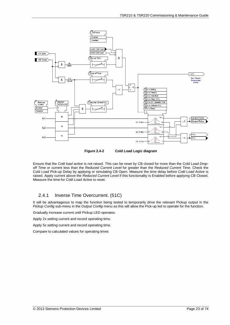
7SR210 & 7SR220 Commissioning & Maintenance Guide
© 2013 Siemens Protection Devices Limited Page 23 of 74
Figure 2.4-2 Cold Load Logic diagram
Ensure that the Cold load active is not raised. This can be reset by CB closed for more than the Cold Load Drop-off Time or current less than the Reduced Current Level for greater than the Reduced Current Time. Check theCold Load Pick-up Delay by applying or simulating CB Open. Measure the time delay before Cold Load Active israised. Apply current above the Reduced Current Level if this functionality is Enabled before applying CB Closed.Measure the time for Cold Load Active to reset.
2.4.1 Inverse Time Overcurrent. (51C)It will be advantageous to map the function being tested to temporarily drive the relevant Pickup output in thePickup Config sub-menu in the Output Config menu as this will allow the Pick-up led to operate for the function.
Gradually increase current until Pickup LED operates.
Apply 2x setting current and record operating time.
Apply 5x setting current and record operating time.
Compare to calculated values for operating times
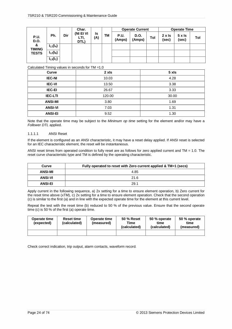
7SR210 & 7SR220 Commissioning & Maintenance Guide
Page 24 of 74 © 2013 Siemens Protection Devices Limited
P.U.D.O.
&TIMINGTESTS
Ph. DirChar.
(NI EI VILTI,DTL)
Is(A) TM
Operate Current Operate TimeP.U.
(Amps)D.O.
(Amps) Tol 2 x Is(sec)
5 x Is(sec) Tol
IL1(IA)
IL2(IB)
IL3(IC)
Calculated Timing values in seconds for TM =1.0Curve 2 xIs 5 xIsIEC-NI 10.03 4.28IEC-VI 13.50 3.38IEC-EI 26.67 3.33IEC-LTI 120.00 30.00ANSI-MI 3.80 1.69ANSI-VI 7.03 1.31ANSI-EI 9.52 1.30
Note that the operate time may be subject to the Minimum op time setting for the element and/or may have aFollower DTL applied.
1.1.1.1 ANSI Reset
If the element is configured as an ANSI characteristic, it may have a reset delay applied. If ANSI reset is selectedfor an IEC characteristic element, the reset will be instantaneous.
ANSI reset times from operated condition to fully reset are as follows for zero applied current and TM = 1.0. Thereset curve characteristic type and TM is defined by the operating characteristic.
Curve Fully operated to reset with Zero current applied & TM=1 (secs)ANSI-MI 4.85ANSI-VI 21.6ANSI-EI 29.1
Apply current in the following sequence, a) 2x setting for a time to ensure element operation, b) Zero current forthe reset time above (xTM), c) 2x setting for a time to ensure element operation. Check that the second operation(c) is similar to the first (a) and in line with the expected operate time for the element at this current level.
Repeat the test with the reset time (b) reduced to 50 % of the previous value. Ensure that the second operatetime (c) is 50 % of the first (a) operate time.
Check correct indication, trip output, alarm contacts, waveform record.
Operate time(expected)
Reset time(calculated)
Operate time(measured)
50 % ResetTime
(calculated)
50 % operatetime
(calculated)
50 % operatetime
(measured)

7SR210 & 7SR220 Commissioning & Maintenance Guide
© 2013 Siemens Protection Devices Limited Page 25 of 74
2.5 Directional Earth Fault Polarity Check (67N)Derived Earth Fault, Measured Earth Fault and Sensitive Earth Fault elements can be set as directional. Theseare polarised from residual voltage, calculated from the 3 phase voltage inputs or the 3Vo input depending on thePhase Voltage Config setting in the CT/VT Config menu.
The relay Char Angle setting is the Characteristic Phase angle of the fault impedance i.e. the phase angle of thefault current with respect to the voltage driving the current. The earth fault functions are polarised from theresidual voltage which is in anti-phase with the fault voltage for a single-phase to earth fault. Care is requiredwhen testing by secondary injection with regard to current and voltage polarity.
To simulate an earth fault on a relay with 3 phase-phase or 3 phase-neutral connected voltage inputs, defined bythe Phase Voltage Config setting of Van,Vbn,Vcn or Va,Vb,Vc, proceed as follows. Balanced 3P voltage shouldfirst be applied, then the phase-neutral voltage magnitude on the faulted phase should be reduced in magnitudewith no change in phase angle to produce Vres and simulate the fault. The fault current, on the faulted phaseonly, should be set at the MTA with respect to the phase-neutral voltage on the faulted phase, e.g. for a relaysetting of -15º, set the phase current to lag the ph-n voltage by 15º.
Alternatively, a single phase voltage source can be used in the above test. The polarity of this voltage, applied tothe faulted phase-neutral alone, must be reversed to produce the same residual voltage (Vres) phase direction asthat produced by the 3P voltage simulation described above.
For the Phase Voltage Config of Vab, Vbc, Vo, the single phase voltage applied to the Vo input is used as thepolarising quantity. The inversion is once again required since this input is designed to measure the residualvoltage directly, as produced by an ‘open delta VT’ arrangement. The current must be set at the MTA with respectto the inversion of this voltage. e.g. for a relay setting of -15º, the phase current must lag the (Vo+180º) voltage by15º, i.e. if Vo is set at 180º, set Iph at -15º.
If the Pickup of one directional Earth Fault element is mapped to an LED, this can be used to check directionalboundaries for pickup and drop-off as the current phase angle is increased and decreased. Note that the DerivedEarth Fault, Measured Earth Fault and Sensitive Earth Fault have separate directional settings and must betested individually.
Figure 2.5-1 Directional Earth Fault Boundary System Angles
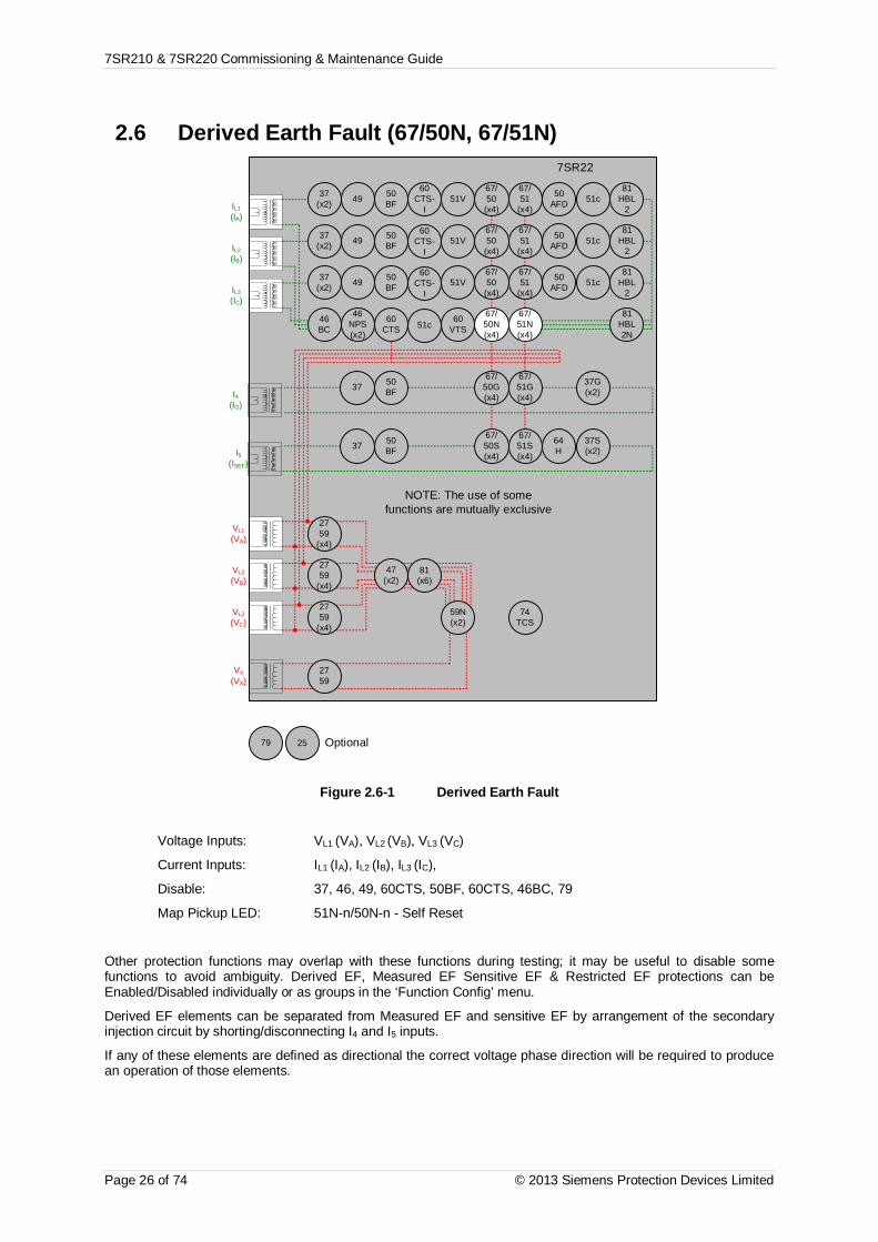
7SR210 & 7SR220 Commissioning & Maintenance Guide
Page 26 of 74 © 2013 Siemens Protection Devices Limited
2.6 Derived Earth Fault (67/50N, 67/51N)7SR22
46BC
46NPS(x2)
37(x2) 49 50
BF
VL1
(VA)
VL2
(VB)
VL3
(VC)
V4
(VX)
IL1
(IA)
81HBL
2
37(x2) 49 50
BFIL2
(IB)
81HBL
2
37(x2) 49 50
BFIL3
(IC)
81HBL
2
60CTS
I4(IG)
I5(ISEF)
74TCS
NOTE: The use of somefunctions are mutually exclusive
67/50
(x4)
67/51
(x4)
67/50N(x4)
67/50
(x4)
67/50
(x4)
67/51
(x4)
67/51
(x4)
67/51N(x4)
67/50G(x4)
67/51G(x4)
67/50S(x4)
67/51S(x4)
64H
2759
2759
(x4)
2759
(x4)
2759
(x4)
47(x2)
81(x6)
79 Optional
59N(x2)
81HBL2N
60VTS
51V
51V
51V
37G(x2)
37S(x2)
51c
60CTS-
I
60CTS-
I
60CTS-
I
37 50BF
37 50BF
25
50AFD
50AFD
50AFD
51c
51c
51c
Figure 2.6-1 Derived Earth Fault
Voltage Inputs: VL1 (VA), VL2 (VB), VL3 (VC)
Current Inputs: IL1 (IA), IL2 (IB), IL3 (IC),
Disable: 37, 46, 49, 60CTS, 50BF, 60CTS, 46BC, 79
Map Pickup LED: 51N-n/50N-n - Self Reset
Other protection functions may overlap with these functions during testing; it may be useful to disable somefunctions to avoid ambiguity. Derived EF, Measured EF Sensitive EF & Restricted EF protections can beEnabled/Disabled individually or as groups in the ‘Function Config’ menu.
Derived EF elements can be separated from Measured EF and sensitive EF by arrangement of the secondaryinjection circuit by shorting/disconnecting I4 and I5 inputs.
If any of these elements are defined as directional the correct voltage phase direction will be required to producean operation of those elements.

7SR210 & 7SR220 Commissioning & Maintenance Guide
© 2013 Siemens Protection Devices Limited Page 27 of 74
2.6.1 Directional PolaritySee section Directional Earth Fault Polarity Check above for testing details.
MTAForward Reverse
Lag (point C) Lead (point A) Lead(point B) Lag (point D)
Pick-up Drop-off Pick-up Drop-off Pick-up Drop-off Pick-up Drop-off
………….MTA-85………..
MTA+85…………
MTA-85…………
MTA-85………...
Derived EF
2.6.2 Definite Time Overcurrent..(50N)If DTL setting is small, gradually increase current until element operates.
If DTL is large apply 0.9x setting, check for no operation, apply 1.1x setting, and check operation
Apply 2x setting current if possible and record operating time
Check correct indication, trip output, alarm contacts, waveform record.
Note that these elements can be set to directional.
Phase Dir. Is(Amps)
DTL(sec)
P.U. CurrentAmps
Operate Time2 x Is NOTES
E
If VTS action is set to BLOCK, this option should be tested. Apply balanced voltage and current. Reduce a-phasevoltage to cause a VTS condition. Increase 3P current and check that the element does not operate.
If VTS action is set to Non-Directional, this option should be tested. Apply balanced voltage and current. Reducea-phase voltage to cause a VTS condition. Increase a-phase current and check that the element operates at itsnormal setting. Reverse the voltage phase direction whilst checking that the element does not reset.
2.6.3 Inverse Time Overcurrent. (51N)It will be advantageous to map the function being tested to temporarily drive the relevant Pickup output in thePickup Config sub-menu in the Output Config menu as this will allow the Pick-up led to operate for the function.
Gradually increase current until Pickup LED operates.
Apply 2x setting current and record operating time.
Apply 5x setting current and record operating time.
Compare to calculated values for operating times

7SR210 & 7SR220 Commissioning & Maintenance Guide
Page 28 of 74 © 2013 Siemens Protection Devices Limited
P.U.D.O.
&TIMINGTESTS
Ph. DirChar.
(NI EI VI LTI,DTL)
Is(A) TM
Operate Current Operate TimeP.U.
(Amps)D.O.
(Amps) Tol 2 x Is(sec)
5 x Is(sec) Tol
E
Calculated Timing values in seconds for TM =1.0Curve 2 xIs 5 xIsIEC-NI 10.03 4.28IEC-VI 13.50 3.38IEC-EI 26.67 3.33IEC-LTI 120.00 30.00ANSI-MI 3.80 1.69ANSI-VI 7.03 1.31ANSI-EI 9.52 1.30
Note that the operate time may be subject to the Minimum op time setting for the element and/or may have aFollower DTL applied.
1.1.1.1 Element Blocking
The Derived Earth Fault elements can be blocked by Binary Input Inhibit, VT Supervision and Inrush Detectoroperation. The Characteristic can be made non-directional by VT Supervision. This functionality should bechecked.
Element BI Inhibits VTS action Inrush Detector
51N-1
51N-2
51N-3
51N-4
50N-1
50N-2
50N-3
50N-4

7SR210 & 7SR220 Commissioning & Maintenance Guide
© 2013 Siemens Protection Devices Limited Page 29 of 74
2.1.1.1 ANSI Reset
If the element is configured as an ANSI characteristic, it may have a reset delay applied. If ANSI reset is selectedfor an IEC characteristic element, the reset will be instantaneous.
ANSI reset times from operated condition to fully reset are as follows for zero applied current and TM = 1.0. Thereset curve characteristic type and TM is defined by the operating characteristic.
Curve Fully operated to reset with Zero current applied & TM=1 (secs)ANSI-MI 4.85ANSI-VI 21.6ANSI-EI 29.1
Apply current in the following sequence, a) 2x setting for a time to ensure element operation, b) Zero current forthe reset time above (xTM), c) 2x setting for a time to ensure element operation. Check that the second operation(c) is similar to the first (a) and in line with the expected operate time for the element at this current level.
Repeat the test with the reset time (b) reduced to 50% of the previous value. Ensure that the second operate time(c) is 50% of the first (a) operate time.
Check correct indication, trip output, alarm contacts, waveform record.
Operate time(expected)
Reset time(calculated)
Operate time(measured)
50% ResetTime
(calculated)
50% operatetime
(calculated)
50% operatetime
(measured)
First test (c) Second Test (c)

7SR210 & 7SR220 Commissioning & Maintenance Guide
Page 30 of 74 © 2013 Siemens Protection Devices Limited
2.7 Measured Earth fault (67/50G,67/51G)7SR22
46BC
46NPS(x2)
37(x2) 49 50
BF
VL1
(VA)
VL2
(VB)
VL3
(VC)
V4
(VX)
IL1
(IA)
81HBL
2
37(x2) 49 50
BFIL2
(IB)
81HBL
2
37(x2) 49 50
BFIL3
(IC)
81HBL
2
60CTS
I4(IG)
I5(ISEF)
74TCS
NOTE: The use of somefunctions are mutually exclusive
67/50
(x4)
67/51
(x4)
67/50N(x4)
67/50
(x4)
67/50
(x4)
67/51
(x4)
67/51
(x4)
67/51N(x4)
67/50G(x4)
67/51G(x4)
67/50S(x4)
67/51S(x4)
64H
2759
2759
(x4)
2759
(x4)
2759
(x4)
47(x2)
81(x6)
79 Optional
59N(x2)
81HBL2N
60VTS
51V
51V
51V
37G(x2)
37S(x2)
51c
60CTS-
I
60CTS-
I
60CTS-
I
37 50BF
37 50BF
25
50AFD
50AFD
50AFD
51c
51c
51c
Figure 2.7-1 Measured Earth Fault
Voltage Inputs: VL1 (VA), VL2 (VB), VL3 (VC) for directional elements
Current Inputs: I4 (IG)
Disable: 50BF, 79
Map Pickup LED: . 51G-n/50G-n - Self Reset
Other protection functions may overlap with these functions during testing, it may be useful to disable somefunctions to avoid ambiguity. Derived EF, Measured EF, Sensitive EF & Restricted EF protections can beEnabled/Disabled individually or as groups in the ‘Function Config’ menu.
Measured EF elements can be separated from Derived EF and Sensitive EF by secondary injection of currentthrough the I4 input circuit only.
If any of these elements are defined as directional the correct voltage phase direction will be required to producean operation of those elements.

7SR210 & 7SR220 Commissioning & Maintenance Guide
© 2013 Siemens Protection Devices Limited Page 31 of 74
2.7.1 Directional PolaritySee section Directional Earth Fault Polarity Check above for testing details.
MTAForward Reverse
Lag (point C) Lead (point A) Lead(point B) Lag (point D)
Pick-up Drop-off Pick-up Drop-off Pick-up Drop-off Pick-up Drop-off
………….MTA-85………..
MTA+85…………
MTA-85…………
MTA-85………...
MeasuredEF
2.7.2 Definite Time Overcurrent..(67/50G)If DTL setting is small, gradually increase current until element operates.
If DTL is large apply 0.9x setting, check for no operation, apply 1.1x setting, and check operation.
Apply 2x setting current if possible and record operating time.
Phase Dir. Is(Amps)
DTL(sec)
P.U. CurrentAmps
OperateTime2 x Is
NOTES
I4
Check correct indication, trip output, alarm contacts, waveform record.
Note that these elements can be set to directional.
If VTS action is set to BLOCK, this option should be tested. Apply balanced voltage and current. Reduce a-phasevoltage to cause a VTS condition. Increase a-phase current and check that the element does not operate.
If VTS action is set to Non-Directional, this option should be tested..Apply balanced voltage and current. Reducea-phase voltage to cause a VTS condition. Increase a-phase current and check that the element operates at itsnormal setting. Reverse the voltage phase direction whilst checking that the element does not reset.
2.7.3 Inverse Time Overcurrent. (67/51G)It will be advantageous to map the function being tested to temporarily drive the relevant Pickup output in thePickup Config sub-menu in the Output Config menu as this will allow the Pick-up led to operate for the function.
Gradually increase current until Pickup LED operates.
Apply 2x setting current and record operating time.
Apply 5x setting current and record operating time.
Compare to calculated values for operating times.

7SR210 & 7SR220 Commissioning & Maintenance Guide
Page 32 of 74 © 2013 Siemens Protection Devices Limited
P.U.D.O.
&TIMINGTESTS
Ph. DirChar.
(NI EI VI LTI,DTL)
Is(A) TM
Operate Current Operate TimeP.U.
(Amps)D.O.
(Amps) Tol 2 x Is(sec)
5 x Is(sec) Tol
I4
Calculated Timing values in seconds for TM =1.0Curve 2 xIs 5 xIsIEC-NI 10.03 4.28IEC-VI 13.50 3.38IEC-EI 26.67 3.33IEC-LTI 120.00 30.00ANSI-MI 3.80 1.69ANSI-VI 7.03 1.31ANSI-EI 9.52 1.30
Note that the operate time may be subject to the Minimum op time setting for the element and/or may have aFollower DTL applied.
If VTS action is set to BLOCK, this option should be tested. Apply balanced voltage and current. Reduce a-phasevoltage to cause a VTS condition. Increase a-phase current and check that the element does not operate.
If VTS action is set to Non-Directional, this option should be tested..Apply balanced voltage and current. Reducea-phase voltage to cause a VTS condition. Increase a-phase current and check that the element operates at itsnormal setting. Reverse the voltage phase direction whilst checking that the element does not reset.
1.1.1.1 Element Blocking
The Measured Earth Fault elements can be blocked by Binary Input Inhibit, VT Supervision and Inrush Detectoroperation. The Characteristic can be made non-directional by VT Supervision. This functionality should bechecked.
Element BI Inhibits VTS action Inrush Detector
51G-1
51G-2
51G-3
51G-4
50G-1
50G-2
50G-3
50G-4
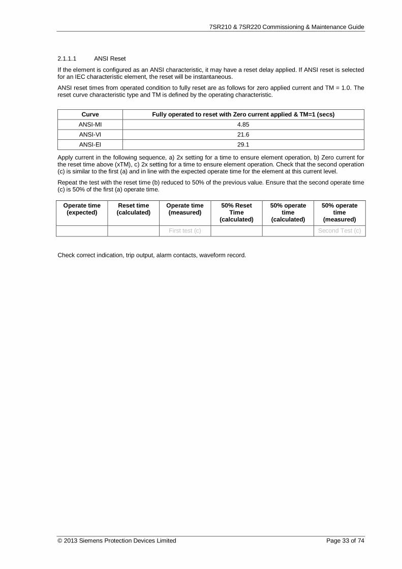
7SR210 & 7SR220 Commissioning & Maintenance Guide
© 2013 Siemens Protection Devices Limited Page 33 of 74
2.1.1.1 ANSI Reset
If the element is configured as an ANSI characteristic, it may have a reset delay applied. If ANSI reset is selectedfor an IEC characteristic element, the reset will be instantaneous.
ANSI reset times from operated condition to fully reset are as follows for zero applied current and TM = 1.0. Thereset curve characteristic type and TM is defined by the operating characteristic.
Curve Fully operated to reset with Zero current applied & TM=1 (secs)ANSI-MI 4.85ANSI-VI 21.6ANSI-EI 29.1
Apply current in the following sequence, a) 2x setting for a time to ensure element operation, b) Zero current forthe reset time above (xTM), c) 2x setting for a time to ensure element operation. Check that the second operation(c) is similar to the first (a) and in line with the expected operate time for the element at this current level.
Repeat the test with the reset time (b) reduced to 50% of the previous value. Ensure that the second operate time(c) is 50% of the first (a) operate time.
Check correct indication, trip output, alarm contacts, waveform record.
Operate time(expected)
Reset time(calculated)
Operate time(measured)
50% ResetTime
(calculated)
50% operatetime
(calculated)
50% operatetime
(measured)
First test (c) Second Test (c)

7SR210 & 7SR220 Commissioning & Maintenance Guide
Page 34 of 74 © 2013 Siemens Protection Devices Limited
2.8 Sensitive Earth fault (67/50S,67/51S)7SR22
46BC
46NPS(x2)
37(x2) 49 50
BF
VL1
(VA)
VL2
(VB)
VL3
(VC)
V4
(VX)
IL1
(IA)
81HBL
2
37(x2) 49 50
BFIL2
(IB)
81HBL
2
37(x2) 49 50
BFIL3
(IC)
81HBL
2
60CTS
I4(IG)
I5(ISEF)
74TCS
NOTE: The use of somefunctions are mutually exclusive
67/50
(x4)
67/51
(x4)
67/50N(x4)
67/50
(x4)
67/50
(x4)
67/51
(x4)
67/51
(x4)
67/51N(x4)
67/50G(x4)
67/51G(x4)
67/50S(x4)
67/51S(x4)
64H
2759
2759
(x4)
2759
(x4)
2759
(x4)
47(x2)
81(x6)
79 Optional
59N(x2)
81HBL2N
60VTS
51V
51V
51V
37G(x2)
37S(x2)
51c
60CTS-
I
60CTS-
I
60CTS-
I
37 50BF
37 50BF
25
50AFD
50AFD
50AFD
51c
51c
51c
Figure 2.8-1 Sensitive Earth Fault
Voltage Inputs: VL1 (VA), VL2 (VB), VL3 (VC) for directional elements
Current Inputs: I5 (ISEF)
Disable: 64H, 50BF, 79
Map Pickup LED: 51SEF-n/50SEF-n - Self Reset
Other protection functions may overlap with these functions during testing; it may be useful to disable somefunctions to avoid ambiguity. Derived EF, Measured EF, Sensitive EF & Restricted EF protections can beEnabled/Disabled individually or as groups in the ‘Function Config’ menu.
Sensitive EF elements can be separated from Derived EF and Measured EF by secondary injection of currentthrough the I5 input circuit only.
If any of these elements are defined as directional the correct voltage phase direction will be required to producean operation of those elements.
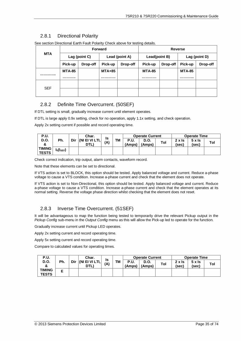
7SR210 & 7SR220 Commissioning & Maintenance Guide
© 2013 Siemens Protection Devices Limited Page 35 of 74
2.8.1 Directional PolaritySee section Directional Earth Fault Polarity Check above for testing details.
MTAForward Reverse
Lag (point C) Lead (point A) Lead(point B) Lag (point D)
Pick-up Drop-off Pick-up Drop-off Pick-up Drop-off Pick-up Drop-off
………….MTA-85………..
MTA+85…………
MTA-85…………
MTA-85………...
SEF
2.8.2 Definite Time Overcurrent. (50SEF)If DTL setting is small, gradually increase current until element operates.
If DTL is large apply 0.9x setting, check for no operation, apply 1.1x setting, and check operation.
Apply 2x setting current if possible and record operating time.
P.U.D.O.
&TIMINGTESTS
Ph. DirChar.
(NI EI VI LTI,DTL)
Is(A) TM
Operate Current Operate TimeP.U.
(Amps)D.O.
(Amps) Tol 2 x Is(sec)
5 x Is(sec) Tol
I5(ISEF)
Check correct indication, trip output, alarm contacts, waveform record.
Note that these elements can be set to directional.
If VTS action is set to BLOCK, this option should be tested. Apply balanced voltage and current. Reduce a-phasevoltage to cause a VTS condition. Increase a-phase current and check that the element does not operate.
If VTS action is set to Non-Directional, this option should be tested. Apply balanced voltage and current. Reducea-phase voltage to cause a VTS condition. Increase a-phase current and check that the element operates at itsnormal setting. Reverse the voltage phase direction whilst checking that the element does not reset.
2.8.3 Inverse Time Overcurrent. (51SEF)It will be advantageous to map the function being tested to temporarily drive the relevant Pickup output in thePickup Config sub-menu in the Output Config menu as this will allow the Pick-up led to operate for the function.
Gradually increase current until Pickup LED operates.
Apply 2x setting current and record operating time.
Apply 5x setting current and record operating time.
Compare to calculated values for operating times.
P.U.D.O.
&TIMINGTESTS
Ph. DirChar.
(NI EI VI LTI,DTL)
Is(A) TM
Operate Current Operate TimeP.U.
(Amps)D.O.
(Amps) Tol 2 x Is(sec)
5 x Is(sec) Tol
E

7SR210 & 7SR220 Commissioning & Maintenance Guide
Page 36 of 74 © 2013 Siemens Protection Devices Limited
Calculated Timing values in seconds for TM =1.0Curve 2 xIs 5 xIsIEC-NI 10.03 4.28IEC-VI 13.50 3.38IEC-EI 26.67 3.33IEC-LTI 120.00 30.00ANSI-MI 3.80 1.69ANSI-VI 7.03 1.31ANSI-EI 9.52 1.30
Note that the operate time may be subject to the Minimum op time setting for the element and/or may have aFollower DTL applied.
If VTS action is set to BLOCK, this option should be tested. Apply balanced voltage and current. Reduce a-phasevoltage to cause a VTS condition. Increase a-phase current and check that the element does not operate.
If VTS action is set to Non-Directional, this option should be tested..Apply balanced voltage and current. Reducea-phase voltage to cause a VTS condition. Increase a-phase current and check that the element operates at itsnormal setting. Reverse the voltage phase direction whilst checking that the element does not reset.
1.1.1.1 Element Blocking
The Sensitive Earth Fault elements can be blocked by Binary Input Inhibit and VT Supervision. The Characteristiccan be made non-directional by VT Supervision. This functionality should be checked.
Element BI Inhibits VTS action
51SEF-1
51SEF-2
51SEF-3
51SEF-4
50SEF-1
50SEF-2
50SEF-3
50SEF-4
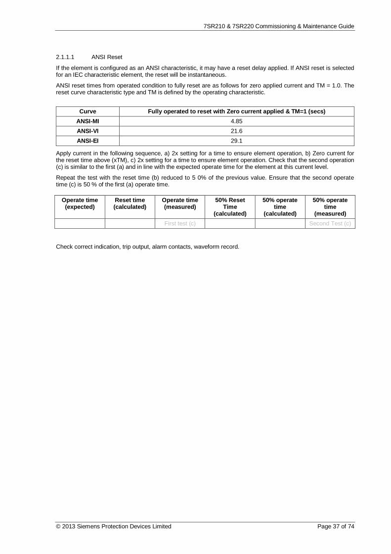
7SR210 & 7SR220 Commissioning & Maintenance Guide
© 2013 Siemens Protection Devices Limited Page 37 of 74
2.1.1.1 ANSI Reset
If the element is configured as an ANSI characteristic, it may have a reset delay applied. If ANSI reset is selectedfor an IEC characteristic element, the reset will be instantaneous.
ANSI reset times from operated condition to fully reset are as follows for zero applied current and TM = 1.0. Thereset curve characteristic type and TM is defined by the operating characteristic.
Curve Fully operated to reset with Zero current applied & TM=1 (secs)ANSI-MI 4.85ANSI-VI 21.6ANSI-EI 29.1
Apply current in the following sequence, a) 2x setting for a time to ensure element operation, b) Zero current forthe reset time above (xTM), c) 2x setting for a time to ensure element operation. Check that the second operation(c) is similar to the first (a) and in line with the expected operate time for the element at this current level.
Repeat the test with the reset time (b) reduced to 5 0% of the previous value. Ensure that the second operatetime (c) is 50 % of the first (a) operate time.
Check correct indication, trip output, alarm contacts, waveform record.
Operate time(expected)
Reset time(calculated)
Operate time(measured)
50% ResetTime
(calculated)
50% operatetime
(calculated)
50% operatetime
(measured)First test (c) Second Test (c)

7SR210 & 7SR220 Commissioning & Maintenance Guide
Page 38 of 74 © 2013 Siemens Protection Devices Limited
2.9 Restricted Earth fault. (64H)7SR22
46BC
46NPS(x2)
37(x2) 49 50
BF
VL1
(VA)
VL2
(VB)
VL3
(VC)
V4
(VX)
IL1
(IA)
81HBL
2
37(x2) 49 50
BFIL2
(IB)
81HBL
2
37(x2) 49 50
BFIL3
(IC)
81HBL
2
60CTS
I4(IG)
I5(ISEF)
74TCS
NOTE: The use of somefunctions are mutually exclusive
67/50
(x4)
67/51
(x4)
67/50N(x4)
67/50
(x4)
67/50
(x4)
67/51
(x4)
67/51
(x4)
67/51N(x4)
67/50G(x4)
67/51G(x4)
67/50S(x4)
67/51S(x4)
64H
2759
2759
(x4)
2759
(x4)
2759
(x4)
47(x2)
81(x6)
79 Optional
59N(x2)
81HBL2N
60VTS
51V
51V
51V
37G(x2)
37S(x2)
51c
60CTS-
I
60CTS-
I
60CTS-
I
37 50BF
37 50BF
25
50AFD
50AFD
50AFD
51c
51c
51c
Figure 2.9-1 Restricted Earth Fault
Voltage Inputs: n/a
Current Inputs: I5 (IREF)
Disable: 51SEF, 50SEF, 79
Map Pickup LED:. 64H - Self Reset
The setting resistance should be measured and the value compared to that specified in the settings data. Bothvalues should be recorded.
Settings Data Resistor Value Measured
The high value of setting resistance R will often interfere with secondary current injection when using a digital testset. It is normal practice in these cases to short out the resistor to allow testing; the shorting link should beremoved after testing.
Since the DTL setting is generally small the pick-up setting can be tested by gradually increasing current untilelement operates. The relay should be disconnected from the current transformers for this test.

7SR210 & 7SR220 Commissioning & Maintenance Guide
© 2013 Siemens Protection Devices Limited Page 39 of 74
Apply 2x setting current if possible and record operating time
Phase Is(Amps)
DTL(sec)
P.U. CurrentAmps Tolerance Operate Time
2 x Is Tolerance
REF
It is also desirable to check the operating voltage achieved with the setting resistor and all parallel CTs connectedbut de-energised. A higher capacity test set will be required for this test. Adequate current must be supplied toprovide the magnetising current of all connected CTs. Precautions should be taken to ensure that no personnelare at risk of contact with any of the energised secondary wiring during the test.
Settings Data Voltage Setting Measured
To complete testing of the REF requires primary injection through the phase and residual (REF) CT in series tosimulate an out of zone fault and ensure stability of the relay. The test can then be repeated with the REF CTsecondary connections reversed to prove operation.
1.1.1.1 Element Blocking
The Restricted Earth Fault element can be blocked by Binary Input Inhibit. This functionality should be checked.
Element BI Inhibits
64H
Check correct indication, trip output, alarm contacts, waveform record.
Check that any shorting links are removed after testing.
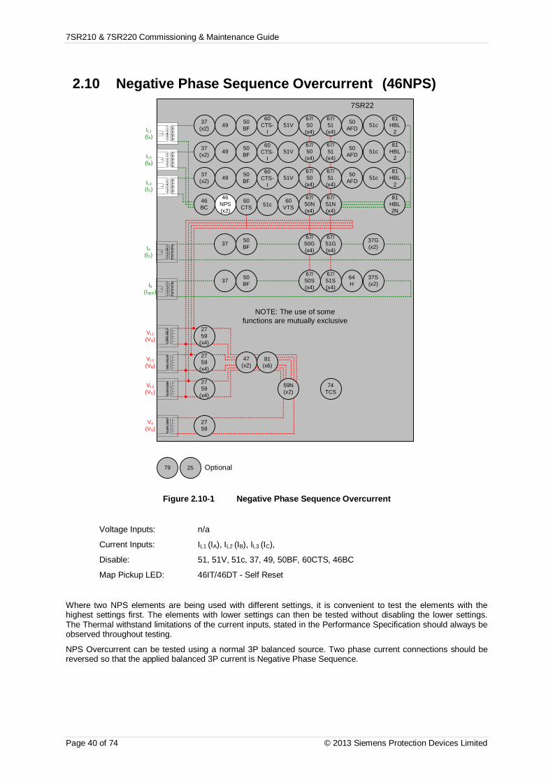
7SR210 & 7SR220 Commissioning & Maintenance Guide
Page 40 of 74 © 2013 Siemens Protection Devices Limited
2.10 Negative Phase Sequence Overcurrent (46NPS)7SR22
46BC
46NPS(x2)
37(x2) 49 50
BF
VL1
(VA)
VL2
(VB)
VL3
(VC)
V4
(VX)
IL1
(IA)
81HBL
2
37(x2) 49 50
BFIL2
(IB)
81HBL
2
37(x2) 49 50
BFIL3
(IC)
81HBL
2
60CTS
I4(IG)
I5(ISEF)
74TCS
NOTE: The use of somefunctions are mutually exclusive
67/50
(x4)
67/51
(x4)
67/50N(x4)
67/50
(x4)
67/50
(x4)
67/51
(x4)
67/51
(x4)
67/51N(x4)
67/50G(x4)
67/51G(x4)
67/50S(x4)
67/51S(x4)
64H
2759
2759
(x4)
2759
(x4)
2759
(x4)
47(x2)
81(x6)
79 Optional
59N(x2)
81HBL2N
60VTS
51V
51V
51V
37G(x2)
37S(x2)
51c
60CTS-
I
60CTS-
I
60CTS-
I
37 50BF
37 50BF
25
50AFD
50AFD
50AFD
51c
51c
51c
Figure 2.10-1 Negative Phase Sequence Overcurrent
Voltage Inputs: n/a
Current Inputs: IL1 (IA), IL2 (IB), IL3 (IC),
Disable: 51, 51V, 51c, 37, 49, 50BF, 60CTS, 46BC
Map Pickup LED: 46IT/46DT - Self Reset
Where two NPS elements are being used with different settings, it is convenient to test the elements with thehighest settings first. The elements with lower settings can then be tested without disabling the lower settings.The Thermal withstand limitations of the current inputs, stated in the Performance Specification should always beobserved throughout testing.
NPS Overcurrent can be tested using a normal 3P balanced source. Two phase current connections should bereversed so that the applied balanced 3P current is Negative Phase Sequence.

7SR210 & 7SR220 Commissioning & Maintenance Guide
© 2013 Siemens Protection Devices Limited Page 41 of 74
2.10.1 Definite Time NPS Overcurrent. (46DT)If DTL setting is small, gradually increase current until element operates.
If DTL is large apply 0.9x setting, check for no operation, apply 1.1x setting, and check operation.
Apply 2x setting current if possible and record operating time
Phase Is(Amps)
DTL(sec)
P.U. CurrentAmps Tolerance Operate Time
2 x Is Tolerance
NPS
Check correct indication, trip output, alarm contacts, waveform record.
2.10.2 Inverse Time NPS Overcurrent. (46IT)It will be advantageous to map the function being tested to temporarily drive the relevant Pickup output in thePickup Config sub-menu in the Output Config menu as this will allow the Pick-up led to operate for the function.
Gradually increase current until Pickup LED operates.
Apply 2x setting current and record operating time.
Apply 5x setting current and record operating time.
Compare to calculated values for operating times
P.U.D.O.
&TIMINGTESTS
Ph. DirChar.
(NI EI VI LTI,DTL)
Is(A) TM
Operate Current Operate TimeP.U.
(Amps)D.O.
(Amps) Tol 2 x Is(sec)
5 x Is(sec) Tol
NPS
Calculated Timing values in seconds for TM =1.0Curve 2 xIs 5 xIsIEC-NI 10.03 4.28IEC-VI 13.50 3.38IEC-EI 26.67 3.33IEC-LTI 120.00 30.00ANSI-MI 3.80 1.69ANSI-VI 7.03 1.31ANSI-EI 9.52 1.30
Note that the operate time may be subject to the Minimum op time setting for the element and/or may have aFollower DTL applied.

7SR210 & 7SR220 Commissioning & Maintenance Guide
Page 42 of 74 © 2013 Siemens Protection Devices Limited
1.1.1.1 ANSI Reset
If the element is configured as an ANSI characteristic, it may have a reset delay applied. If ANSI reset is selectedfor an IEC characteristic element, the reset will be instantaneous.
ANSI reset times from operated condition to fully reset are as follows for zero applied current and TM = 1.0. Thereset curve characteristic type and TM is defined by the operating characteristic.
Curve Fully operated to reset with Zero current applied & TM=1 (secs)ANSI-MI 4.85ANSI-VI 21.6ANSI-EI 29.1
Apply current in the following sequence, a) 2x setting for a time to ensure element operation, b) Zero current forthe reset time above (xTM), c) 2x setting for a time to ensure element operation. Check that the second operation(c) is similar to the first (a) and in line with the expected operate time for the element at this current level.
Repeat the test with the reset time (b) reduced to 50 % of the previous value. Ensure that the second operatetime (c) is 50 % of the first (a) operate time.
2.1.1.1 Element Blocking
The NPS Overcurrent elements can be blocked by Binary Input Inhibit. This functionality should be checked.
Element BI Inhibits
46IT
46DT
Check correct indication, trip output, alarm contacts, waveform record.
When testing is complete reinstate any of the disabled functions.
Operate time(expected)
Reset time(calculated)
Operate time(measured)
50% ResetTime
(calculated)
50% operatetime
(calculated)
50% operatetime
(measured)First test (c) Second Test
(c)

7SR210 & 7SR220 Commissioning & Maintenance Guide
© 2013 Siemens Protection Devices Limited Page 43 of 74
2.11 Undercurrent. (37)7SR22
46BC
46NPS(x2)
37(x2) 49 50
BF
VL1
(VA)
VL2
(VB)
VL3
(VC)
V4
(VX)
IL1
(IA)
81HBL
2
37(x2) 49 50
BFIL2
(IB)
81HBL
2
37(x2) 49 50
BFIL3
(IC)
81HBL
2
60CTS
I4(IG)
I5(ISEF)
74TCS
NOTE: The use of somefunctions are mutually exclusive
67/50
(x4)
67/51
(x4)
67/50N(x4)
67/50
(x4)
67/50
(x4)
67/51
(x4)
67/51
(x4)
67/51N(x4)
67/50G(x4)
67/51G(x4)
67/50S(x4)
67/51S(x4)
64H
2759
2759
(x4)
2759
(x4)
2759
(x4)
47(x2)
81(x6)
79 Optional
59N(x2)
81HBL2N
60VTS
51V
51V
51V
37G(x2)
37S(x2)
51c
60CTS-
I
60CTS-
I
60CTS-
I
37 50BF
37 50BF
25
50AFD
50AFD
50AFD
51c
51c
51c
Figure 2.11-1 Undercurrent
Voltage Inputs: n/a
Current Inputs: IL1 (IA), IL2 (IB), IL3 (IC),
Disable: 51N, 51G, 46, 60CTS, 46BC
Map Pickup LED: 37-n - Self Reset
If two Undercurrent 37 elements are used with different settings, it is convenient to test the element with thelowest setting first. The higher setting element can then be tested without interference from the other element.
Apply 3P balanced current at a level above the Undercurrent 37-n setting until the element resets.
If DTL setting is small, gradually reduce any each phase current in turn until element operates.
If DTL is large apply 1.1x setting, check for no operation, apply 0.9x setting, and check operation
Testing of this element phase by phase may cause inadvertent operation of the 46 NPS Overcurrent elements.
Apply 0.5x setting current and record operating time.
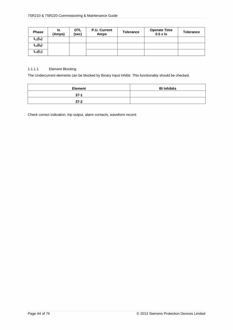
7SR210 & 7SR220 Commissioning & Maintenance Guide
Page 44 of 74 © 2013 Siemens Protection Devices Limited
Phase Is(Amps)
DTL(sec)
P.U. CurrentAmps Tolerance Operate Time
0.5 x Is Tolerance
IL1(IA)
IL2(IB)
IL3(IC)
1.1.1.1 Element Blocking
The Undercurrent elements can be blocked by Binary Input Inhibit. This functionality should be checked.
Element BI Inhibits
37-1
37-2
Check correct indication, trip output, alarm contacts, waveform record.
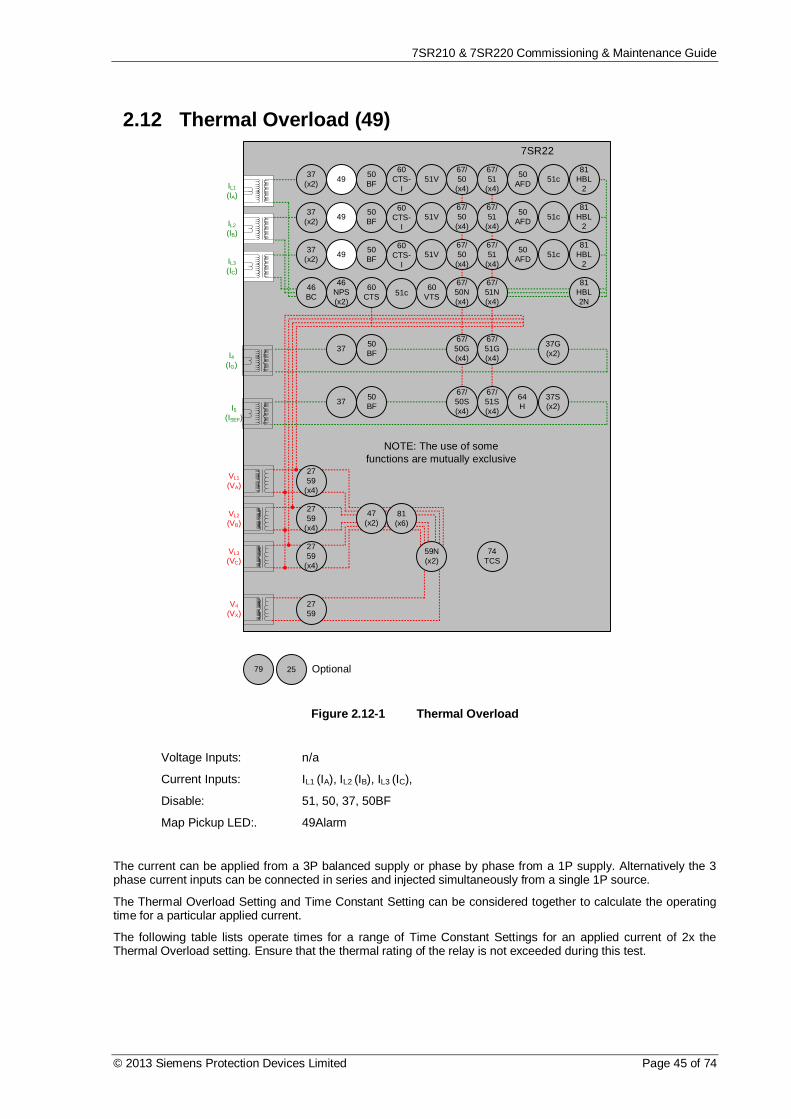
7SR210 & 7SR220 Commissioning & Maintenance Guide
© 2013 Siemens Protection Devices Limited Page 45 of 74
2.12 Thermal Overload (49)7SR22
46BC
46NPS(x2)
37(x2) 49 50
BF
VL1
(VA)
VL2
(VB)
VL3
(VC)
V4
(VX)
IL1
(IA)
81HBL
2
37(x2) 49 50
BFIL2
(IB)
81HBL
2
37(x2) 49 50
BFIL3
(IC)
81HBL
2
60CTS
I4(IG)
I5(ISEF)
74TCS
NOTE: The use of somefunctions are mutually exclusive
67/50
(x4)
67/51
(x4)
67/50N(x4)
67/50
(x4)
67/50
(x4)
67/51
(x4)
67/51
(x4)
67/51N(x4)
67/50G(x4)
67/51G(x4)
67/50S(x4)
67/51S(x4)
64H
2759
2759
(x4)
2759
(x4)
2759
(x4)
47(x2)
81(x6)
79 Optional
59N(x2)
81HBL2N
60VTS
51V
51V
51V
37G(x2)
37S(x2)
51c
60CTS-
I
60CTS-
I
60CTS-
I
37 50BF
37 50BF
25
50AFD
50AFD
50AFD
51c
51c
51c
Figure 2.12-1 Thermal Overload
Voltage Inputs: n/a
Current Inputs: IL1 (IA), IL2 (IB), IL3 (IC),
Disable: 51, 50, 37, 50BF
Map Pickup LED:. 49Alarm
The current can be applied from a 3P balanced supply or phase by phase from a 1P supply. Alternatively the 3phase current inputs can be connected in series and injected simultaneously from a single 1P source.
The Thermal Overload Setting and Time Constant Setting can be considered together to calculate the operatingtime for a particular applied current.
The following table lists operate times for a range of Time Constant Settings for an applied current of 2x theThermal Overload setting. Ensure that the thermal rating of the relay is not exceeded during this test.

7SR210 & 7SR220 Commissioning & Maintenance Guide
Page 46 of 74 © 2013 Siemens Protection Devices Limited
Time Constant (mins) Operate Time (sec)1 17.32 34.53 51.84 695 86.310 17315 25920 34525 43230 51.850 863
100 1726
The Thermal State must be in the fully reset condition in order to measure the operate time correctly. This can beachieved by setting change in the Thermal protection settings menu or by pressing the Test/Reset button whenthe Thermal Meter is shown in the Instruments Mode.Reset the thermal State then apply 2x the Overload Setting current.
Calculated Operate Time (s) Measured Operate Time (s)
If the Thermal Overload Capacity Alarm is used, this can be tested by monitoring the Thermal Capacity in theinstruments menu. If the Thermal time constant is longer than a few minutes, this can be assessed during thetiming test above. If the Time Constant is less than a few minutes, a lower multiple of current will be required suchthat the rate of capacity increase is slowed to allow monitoring of the instrument to be accurate.
Capacity Alarm Setting Measured
1.1.1.1 Element Blocking
The Thermal element can be blocked by Binary Input Inhibit. This functionality should be checked.
Element BI Inhibits
49

7SR210 & 7SR220 Commissioning & Maintenance Guide
© 2013 Siemens Protection Devices Limited Page 47 of 74
2.13 Over/Under Voltage
2.13.1 Phase Under/Over Voltage. (27/59)
7SR22
46BC
46NPS(x2)
37(x2) 49 50
BF
VL1
(VA)
VL2
(VB)
VL3
(VC)
V4
(VX)
IL1
(IA)
81HBL
2
37(x2) 49 50
BFIL2
(IB)
81HBL
2
37(x2) 49 50
BFIL3
(IC)
81HBL
2
60CTS
I4(IG)
I5(ISEF)
74TCS
NOTE: The use of somefunctions are mutually exclusive
67/50
(x4)
67/51
(x4)
67/50N(x4)
67/50
(x4)
67/50
(x4)
67/51
(x4)
67/51
(x4)
67/51N(x4)
67/50G(x4)
67/51G(x4)
67/50S(x4)
67/51S(x4)
64H
2759
2759
(x4)
2759
(x4)
2759
(x4)
47(x2)
81(x6)
79 Optional
59N(x2)
81HBL2N
60VTS
51V
51V
51V
37G(x2)
37S(x2)
51c
60CTS-
I
60CTS-
I
60CTS-
I
37 50BF
37 50BF
25
50AFD
50AFD
50AFD
51c
51c
51c
Figure 2.13-1 Phase Under/Over Voltage
Voltage Inputs: VL1 (VA), VL2 (VB), VL3 (VC)
Current Inputs: n/a apply zero current to stabilize other functions
Disable: 47, 59N, 60VTS
Map Pickup LED:. 27/59-n - Self Reset
Where more than one Undervoltage (27) elements are being used with different settings, it is convenient to testthe elements with the lowest settings first. The elements with higher settings can then be tested without disablingthe lower settings.
Note that if the voltage is reduced below the 27UVG setting, the function may be blocked. VTS operation mayalso block the 27 Undervoltage function. Current inputs are not normally required to stabilise the relay duringvoltage element testing.
If the ‘O/P Phases’ is set to ‘All’, the voltage on all phases must be reduced simultaneously. Otherwise the 3phases should be tested individually.

7SR210 & 7SR220 Commissioning & Maintenance Guide
Page 48 of 74 © 2013 Siemens Protection Devices Limited
If the DTL is short, starting from nominal voltage, slowly decrease the applied 3P or VL1 test voltage until thePickup LED (temporarily mapped) is lit. Record the operate voltage. The LED should light at setting Volts +/- 5 %.Slowly increase the input voltage until the LED extinguishes. Record the reset voltage to check the ‘Hysteresis’setting. If the DTL is long, the operate level level should be checked by applying a voltage of 90 % of settingvoltage. Check Hysteresis by resetting element to the operate level setting plus the hysteresis setting.
Connect the relevant output contact(s) to stop the test set. Step the applied voltage to a level below the setting.The test set should be stopped at the operate time setting +/- 5 %
Test inputs VL2 and VL3 by repeating the above if necessary.
When testing is complete reinstate any of the disabled functions.
Where more than one overvoltage (59) elements are being used with different settings, it is convenient to test theelements with the highest settings first. The elements with lower settings can then be tested without disabling thehigher settings.
If the ‘O/P Phases’ is set to ‘All’, the voltage on all phases must be increased simultaneously. Otherwise the 3phases should be tested individually. If the DTL setting is short, starting from nominal voltage, slowly increase theapplied 3P or VL1 test voltage until the Pickup LED (temporarily mapped) is lit. The LED should light at settingVolts +/- 5 % Decrease the input voltage to nominal Volts and the LED will extinguish. Record the reset voltage tocheck the ‘Hysteresis’ setting. If the DTL setting is long, the operate level can be checked by applying 100 % ofsetting to cause operation followed by setting minus the Hysteresis setting to cause reset.
Connect the relevant output contact(s) to stop the test set. Step the applied voltage to a level above the setting.The test set should be stopped at the operate time setting +/- 5 %.
Test inputs VL2 and VL3 by repeating the above if necessary.
Phase27/59
setting(Volts)
U/O DTL(sec) Hyst. D.O.
(calculated)P.U.Volts
D.OVolts
Op. Time2x Vs (OV)
0.5x Vs (UV)UV
Guard Tol
V1(VA)
V2(VB)
V3(VC)
1.1.1.1 Element Blocking
The NPS Overcurrent elements can be blocked by Binary Input Inhibit and VT Supervision. This functionalityshould be checked.
Element BI Inhibits VT Supervision
27/59-1
27/59-2
27/59-3
27/59-4
When testing is complete reinstate any of the disabled functions.

7SR210 & 7SR220 Commissioning & Maintenance Guide
© 2013 Siemens Protection Devices Limited Page 49 of 74
2.13.2 Undervoltage Guard (27/59UVG)
If any 27 Undervoltage element is set to be inhibited by the 27 Undervoltage Guard element, this function shouldbe tested.
Connect the test voltage inputs to suit the installation wiring diagram utilising any test socket facilities available. Itmay be useful to temporarily map an LED as ‘General Pickup’ to assist during testing. 27UVG operation will resetthe General Pickup if no other element is operated. This LED should not be set as ‘Hand Reset’ in the Outputmatrix.
Starting from nominal voltage, apply a step decrease to the applied voltage to a level below the 27 Undervoltagesetting but above the 27UVG setting such that an Undervoltage element operation occurs. Slowly reduce theapplied voltage until the 27 Undervoltage element resets, this can be detected by the General Pickup LED reset ifno other element is operated (this includes any Undervoltage element which is not UV Guarded).
Phase Vs(Volts) Tol V element
Used for testBlocked
Volts NOTES
UVG

7SR210 & 7SR220 Commissioning & Maintenance Guide
Page 50 of 74 © 2013 Siemens Protection Devices Limited
2.13.3 VX Under/Over Voltage. (Vx 27/59)
7SR22
46BC
46NPS(x2)
37(x2) 49 50
BF
VL1
(VA)
VL2
(VB)
VL3
(VC)
V4
(VX)
IL1
(IA)
81HBL
2
37(x2) 49 50
BFIL2
(IB)
81HBL
2
37(x2) 49 50
BFIL3
(IC)
81HBL
2
60CTS
I4(IG)
I5(ISEF)
74TCS
NOTE: The use of somefunctions are mutually exclusive
67/50
(x4)
67/51
(x4)
67/50N(x4)
67/50
(x4)
67/50
(x4)
67/51
(x4)
67/51
(x4)
67/51N(x4)
67/50G(x4)
67/51G(x4)
67/50S(x4)
67/51S(x4)
64H
2759
2759
(x4)
2759
(x4)
2759
(x4)
47(x2)
81(x6)
79 Optional
59N(x2)
81HBL2N
60VTS
51V
51V
51V
37G(x2)
37S(x2)
51c
60CTS-
I
60CTS-
I
60CTS-
I
37 50BF
37 50BF
25
50AFD
50AFD
50AFD
51c
51c
51c
Figure 2.13-2 Vx Under/Over Voltage
Voltage Inputs: V4 (VX)
Current Inputs: n/a apply zero current to stabilize other functions
Disable:
Map Pickup LED:. Vx 27/59 - Self Reset
If DTL setting is small, gradually increase single phase voltage applied to Vx input until element operates if theelement is Overvoltage. Alternatively, if the element is Undervoltage, increase single phase voltage applied to Vxinput until element operates.
If DTL is large, for Overvoltage elements, apply 0.9x setting, check for no operation, apply 1.1x setting, checkoperation. For Undervoltage elements, apply 1.1x setting, check for no operation, apply 0.9x setting, checkoperation.
Apply 2x setting voltage if possible and record operating time.
Starting with the element in the operated condition, gradually increase or decrease the applied voltage until theelement resets. Measure the reset voltage level to check the 27/59 Hysteresis setting.

7SR210 & 7SR220 Commissioning & Maintenance Guide
© 2013 Siemens Protection Devices Limited Page 51 of 74
Phase27/59
setting(Volts)
U/O DTL(sec) Hyst. D.O.
(calculated)P.U.Volts
D.OVolts
Op. Time2x Vs (OV)
0.5x Vs(UV)
Tolerence
V4(Vx)
1.1.1.1 Element Blocking
The Vx Under/Over Voltage elements can be blocked by Binary Input Inhibit and VT Supervision. Thisfunctionality should be checked.
Element BI Inhibits VT Supervision
27/59x
Check correct indication, trip output, alarm contacts, waveform record.

7SR210 & 7SR220 Commissioning & Maintenance Guide
Page 52 of 74 © 2013 Siemens Protection Devices Limited
2.13.4 NPS Overvoltage (47)
7SR22
46BC
46NPS(x2)
37(x2) 49 50
BF
VL1
(VA)
VL2
(VB)
VL3
(VC)
V4
(VX)
IL1
(IA)
81HBL
2
37(x2) 49 50
BFIL2
(IB)
81HBL
2
37(x2) 49 50
BFIL3
(IC)
81HBL
2
60CTS
I4(IG)
I5(ISEF)
74TCS
NOTE: The use of somefunctions are mutually exclusive
67/50
(x4)
67/51
(x4)
67/50N(x4)
67/50
(x4)
67/50
(x4)
67/51
(x4)
67/51
(x4)
67/51N(x4)
67/50G(x4)
67/51G(x4)
67/50S(x4)
67/51S(x4)
64H
2759
2759
(x4)
2759
(x4)
2759
(x4)
47(x2)
81(x6)
79 Optional
59N(x2)
81HBL2N
60VTS
51V
51V
51V
37G(x2)
37S(x2)
51c
60CTS-
I
60CTS-
I
60CTS-
I
37 50BF
37 50BF
25
50AFD
50AFD
50AFD
51c
51c
51c
Figure 2.13-3 NPS Overvoltage
Voltage Inputs: VL1 (VA), VL2 (VB), VL3 (VC)
Current Inputs: n/a apply zero current to stabilize other functions
Disable: 27/59, 59N, 60VTS
Map Pickup LED:. 47-n - Self Reset
Where two NPS elements are being used with different settings, it is convenient to test the elements with thehighest settings first. The elements with lower settings can then be tested without disabling the lower settings.
NPS Overvoltage can be tested using a normal 3P balanced source. Two phase voltage connections should bereversed so that the applied balanced 3P voltage is Negative Phase Sequence.
If the 47-n delay is small, gradually increased the applied balanced 3P voltage until element operates.
If DTL is large apply 0.9x setting, check for no operation, apply 1.1x setting, and check operation.
Apply 2x setting current if possible and record operating time.
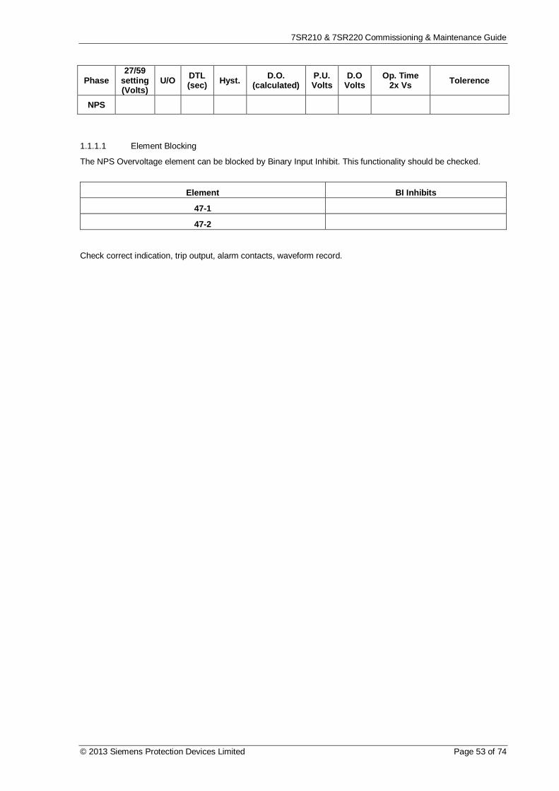
7SR210 & 7SR220 Commissioning & Maintenance Guide
© 2013 Siemens Protection Devices Limited Page 53 of 74
Phase27/59
setting(Volts)
U/O DTL(sec) Hyst. D.O.
(calculated)P.U.Volts
D.OVolts
Op. Time2x Vs Tolerence
NPS
1.1.1.1 Element Blocking
The NPS Overvoltage element can be blocked by Binary Input Inhibit. This functionality should be checked.
Element BI Inhibits
47-1
47-2
Check correct indication, trip output, alarm contacts, waveform record.

7SR210 & 7SR220 Commissioning & Maintenance Guide
Page 54 of 74 © 2013 Siemens Protection Devices Limited
2.13.5 Neutral Overvoltage (59N)
7SR22
46BC
46NPS(x2)
37(x2) 49 50
BF
VL1
(VA)
VL2
(VB)
VL3
(VC)
V4
(VX)
IL1
(IA)
81HBL
2
37(x2) 49 50
BFIL2
(IB)
81HBL
2
37(x2) 49 50
BFIL3
(IC)
81HBL
2
60CTS
I4(IG)
I5(ISEF)
74TCS
NOTE: The use of somefunctions are mutually exclusive
67/50
(x4)
67/51
(x4)
67/50N(x4)
67/50
(x4)
67/50
(x4)
67/51
(x4)
67/51
(x4)
67/51N(x4)
67/50G(x4)
67/51G(x4)
67/50S(x4)
67/51S(x4)
64H
2759
2759
(x4)
2759
(x4)
2759
(x4)
47(x2)
81(x6)
79 Optional
59N(x2)
81HBL2N
60VTS
51V
51V
51V
37G(x2)
37S(x2)
51c
60CTS-
I
60CTS-
I
60CTS-
I
37 50BF
37 50BF
25
50AFD
50AFD
50AFD
51c
51c
51c
Figure 2.13-4 Neutral Overvoltage
Voltage Inputs: VL1 (VA), VL2 (VB), VL3 (VC)
Current Inputs: n/a apply zero current to stabilize other functions
Disable: 27/59, 47, 60VTS
Map Pickup LED:. 59N-n - Self Reset
The voltage source for the Neutral Overvoltage 59N function can be set as either Vn , calculated from the applied3 phase voltage inputs or Vx, the V4 input. Apply test voltage to 1 phase input or V4 input to suit.
2.13.6 Definite Time (59NDT)If DTL setting is small, gradually increase single phase voltage until element operates.
If DTL is large apply 0.9x setting, check for no operation, apply 1.1x setting, and check operation.
Apply 2x setting voltage if possible and record operating time.

7SR210 & 7SR220 Commissioning & Maintenance Guide
© 2013 Siemens Protection Devices Limited Page 55 of 74
Phase Vs(Volts)
DTL(sec)
P.U. CurrentVolts
Operate Time2x Vs
Tolerence
E
Check correct indication, trip output, alarm contacts, waveform record.
2.13.7 Inverse Time (59NIT)It will be advantageous to map the function being tested to temporarily drive the relevant Pickup output in thePickup Config sub-menu in the Output Config menu as this will allow the Pick-up led to operate for the function.
Gradually increase voltage until Pickup LED operates.
Apply 2x setting voltage and record operating time,
Apply a higher multiple of setting voltage and record operating time.
Compare to calculated values for operating times from:
( ) [ ] úû
ùêë
é-
=1
1)secVsVnop Mondst
Where M = Time multiplier and Vn/Vs = multiple of setting.
P.U.D.O.
&TIMINGTESTS
Ph. Vs(V) TM
Operate Voltage Operate TimeP.U.
(Volts)D.O.
(Volts) Tol 2.x Vs(sec)
x Vs(sec) Tol
E
1.1.1.1 Element Blocking
The Neutral Overvoltage elements can be blocked by Binary Input Inhibit. This functionality should be checked.
Element BI Inhibits
59NIT
59NDT
Check correct indication, trip output, alarm contacts, waveform record.
When testing is complete reinstate any of the disabled functions.

7SR210 & 7SR220 Commissioning & Maintenance Guide
Page 56 of 74 © 2013 Siemens Protection Devices Limited
2.13.8 Under/Over Frequency (81)
7SR22
46BC
46NPS(x2)
37(x2) 49 50
BF
VL1
(VA)
VL2
(VB)
VL3
(VC)
V4
(VX)
IL1
(IA)
81HBL
2
37(x2) 49 50
BFIL2
(IB)
81HBL
2
37(x2) 49 50
BFIL3
(IC)
81HBL
2
60CTS
I4(IG)
I5(ISEF)
74TCS
NOTE: The use of somefunctions are mutually exclusive
67/50
(x4)
67/51
(x4)
67/50N(x4)
67/50
(x4)
67/50
(x4)
67/51
(x4)
67/51
(x4)
67/51N(x4)
67/50G(x4)
67/51G(x4)
67/50S(x4)
67/51S(x4)
64H
2759
2759
(x4)
2759
(x4)
2759
(x4)
47(x2)
81(x6)
79 Optional
59N(x2)
Note:Example showsVoltage Config =Van, Vbn, Vcn
81HBL2N
81HBL2G
60CTS-
I
60VTS
51V
51V
51V
37G(x2)
37S(x2)
51c
51c
51c
Figure 2.13-5 Under/Over Frequency
Voltage Inputs: VL1 (VA), VL2 (VB), VL3 (VC)
Current Inputs: n/a apply zero current to stabilize other functions.
Disable:
Map Pickup LED: 81-n - Self Reset.
This function can be tested by application of 1P or 3P voltage. For Over-frequency, the elements with the highestsetting should be tested first and for Under-frequency the elements with the lowest settings should be tested first.The elements with other settings can then be tested without need to disable the elements already tested. Notethat the relay is designed to track the gradual changes in power system frequency and that sudden step changesin frequency during testing do not reflect normal system operation. Normal ‘instantaneous’ operation of thefrequency element is 140 ms to 175 ms in line with the Performance Specification. Application of sudden stepchanges to frequency can add additional delay which can produce misleading test results.
Gradually increase/decrease applied voltage frequency until 81-n operation occurs. Elements set for moreextreme frequency fluctuation should be tested first with lesser elements disabled.

7SR210 & 7SR220 Commissioning & Maintenance Guide
© 2013 Siemens Protection Devices Limited Page 57 of 74
If the 81-n Delay setting is long it will be advantageous to map the function to temporarily drive the relevantPickup output in the Pickup Config sub-menu in the Output Config menu as this will allow the Pick-up led tooperate for the function. If the delay setting is short the operation of the element can be easily checked directly.
The frequency should then be gradually decreased/increased until the element resets. The reset frequency canbe used to check the Hysteresis setting.
If the element is set as 81-n U/V Guarded, The applied voltage must be above the 81 UV Guard Setting in theU/O Frequency menu.
Apply setting frequency +0.5 Hz for Over-frequency or -0.5 Hz for Under-frequency and record operating time.
Starting with the element in the operated condition, gradually increase or decrease the applied voltage until theelement resets. Measure the reset voltage level to check the 81 Hysteresis setting.
F(Hertz)
U/O DTL(sec)
Hyst. D.O.(calc.)
P.U.FreqHertz
D.O.Freq.Hertz
OperateTime
+/- 0.5Hz
UVGuard
NOTES
If the element is set as 81-nU/V Guarded, this setting can be tested by applying the test voltage at a level belowthe 81 U/V Guard Setting at a frequency in the operate range. Increase the voltage until the relay operates.
UVG UVGSetting(Volts)
Freq elementUsed for test
BlockedVolts (D.O.)
UnblockedVolts (P.U.)
NOTES
U/OFreq
1.1.1.1 Element Blocking
The U/O Frequency elements can be blocked by Binary Input Inhibit. This functionality should be checked.
Element BI Inhibits
81-1
81-2
81-3
81-4
81-5
81-6
Check correct indication, trip output, alarm contacts, waveform record.
When testing is complete reinstate any of the disabled functions.
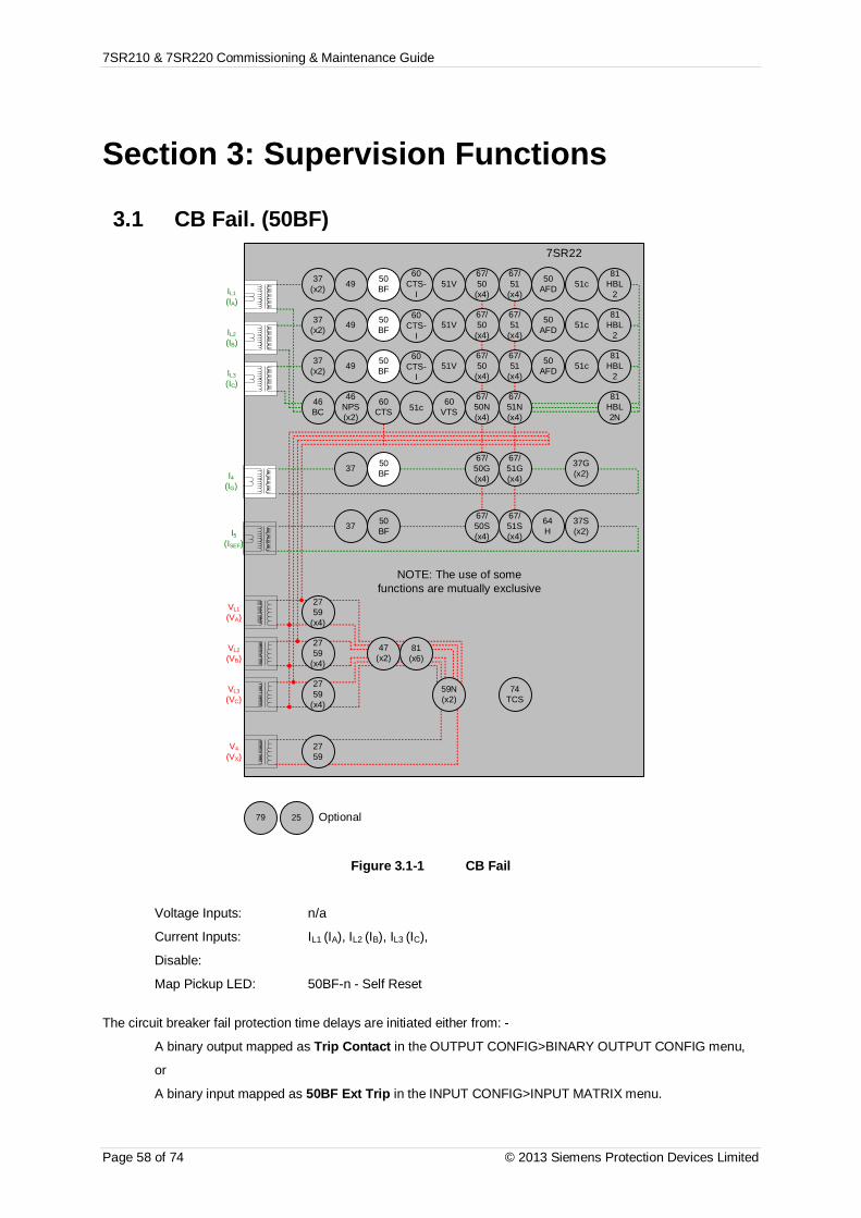
7SR210 & 7SR220 Commissioning & Maintenance Guide
Page 58 of 74 © 2013 Siemens Protection Devices Limited
Section 3: Supervision Functions
3.1 CB Fail. (50BF)7SR22
46BC
46NPS(x2)
37(x2) 49 50
BF
VL1
(VA)
VL2
(VB)
VL3
(VC)
V4
(VX)
IL1
(IA)
81HBL
2
37(x2) 49 50
BFIL2
(IB)
81HBL
2
37(x2) 49 50
BFIL3
(IC)
81HBL
2
60CTS
I4(IG)
I5(ISEF)
74TCS
NOTE: The use of somefunctions are mutually exclusive
67/50
(x4)
67/51
(x4)
67/50N(x4)
67/50
(x4)
67/50
(x4)
67/51
(x4)
67/51
(x4)
67/51N(x4)
67/50G(x4)
67/51G(x4)
67/50S(x4)
67/51S(x4)
64H
2759
2759
(x4)
2759
(x4)
2759
(x4)
47(x2)
81(x6)
79 Optional
59N(x2)
81HBL2N
60VTS
51V
51V
51V
37G(x2)
37S(x2)
51c
60CTS-
I
60CTS-
I
60CTS-
I
37 50BF
37 50BF
25
50AFD
50AFD
50AFD
51c
51c
51c
Figure 3.1-1 CB Fail
Voltage Inputs: n/a
Current Inputs: IL1 (IA), IL2 (IB), IL3 (IC),
Disable:
Map Pickup LED: 50BF-n - Self Reset
The circuit breaker fail protection time delays are initiated either from: -
A binary output mapped as Trip Contact in the OUTPUT CONFIG>BINARY OUTPUT CONFIG menu,
or
A binary input mapped as 50BF Ext Trip in the INPUT CONFIG>INPUT MATRIX menu.

7SR210 & 7SR220 Commissioning & Maintenance Guide
© 2013 Siemens Protection Devices Limited Page 59 of 74
Apply a trip condition by injection of current to cause operation of a suitable protection element. Allow current tocontinue after the trip at a level of 110 % of the 50BF Setting current level on any phase. Measure the time foroperation of operation of 50BF-1 Delay and 50BF-2 Delay. Repeat the sequence with current at 90 % of the 50BFSetting.current level after the element trip and check for no CB Fail operation.
50BF Setting (xIn) Test Current 50BF-1 Delay 50BF-2 Delay
(110%)
(90%) No Operation.. No Operation..
50BF CB Faulty Operation No Delay Operation No Delay
50BF-I4 Setting(xIn) Test Current 50BF-1 Delay 50BF-2 Delay
(110%)
(90%) No Operation.. No Operation..
50BF CB Faulty Operation No Delay Operation No Delay
1.1.1.1 Element Blocking
The CB Fail function can be blocked by Binary Input Inhibit. This functionality should be checked.
Element BI Inhibits
50BF
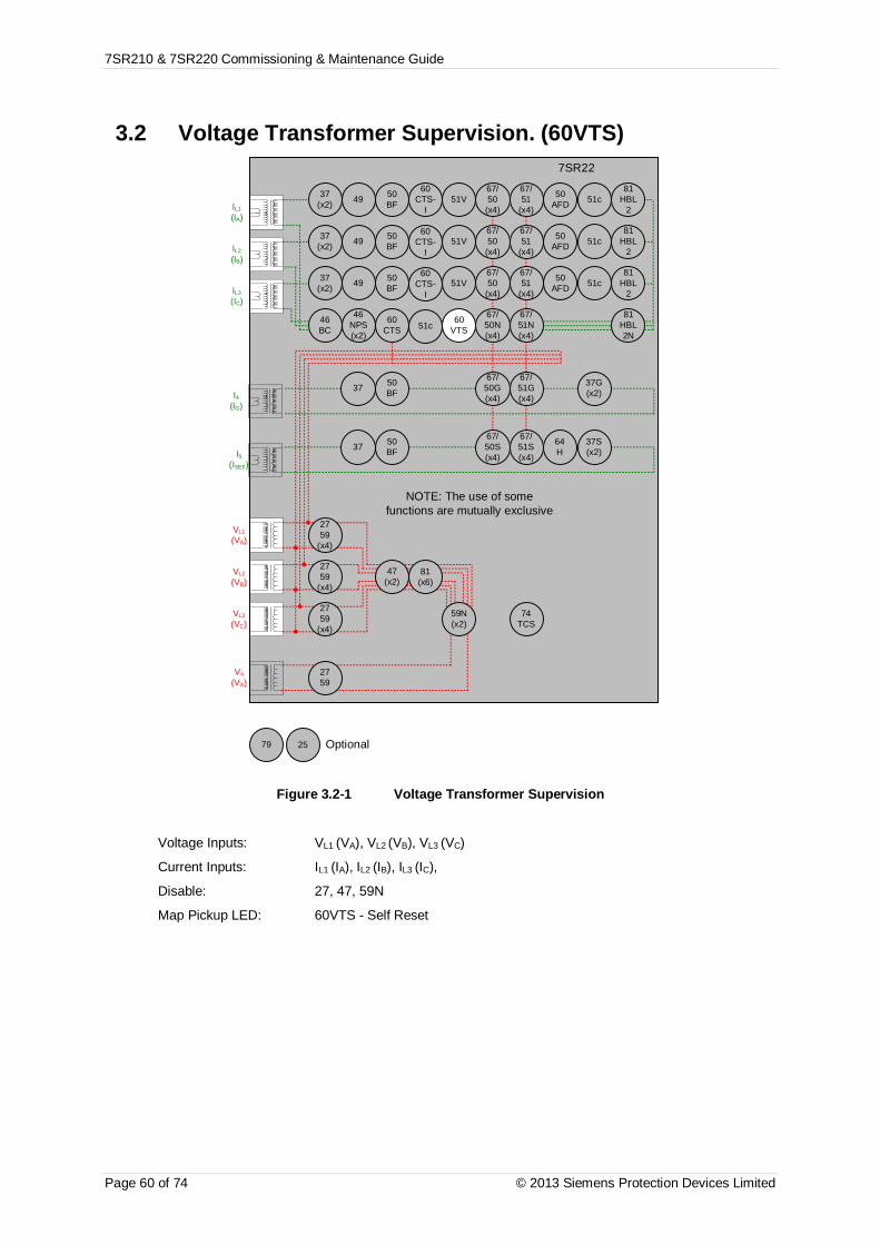
7SR210 & 7SR220 Commissioning & Maintenance Guide
Page 60 of 74 © 2013 Siemens Protection Devices Limited
3.2 Voltage Transformer Supervision. (60VTS)7SR22
46BC
46NPS(x2)
37(x2) 49 50
BF
VL1
(VA)
VL2
(VB)
VL3
(VC)
V4
(VX)
IL1
(IA)
81HBL
2
37(x2) 49 50
BFIL2
(IB)
81HBL
2
37(x2) 49 50
BFIL3
(IC)
81HBL
2
60CTS
I4(IG)
I5(ISEF)
74TCS
NOTE: The use of somefunctions are mutually exclusive
67/50
(x4)
67/51
(x4)
67/50N(x4)
67/50
(x4)
67/50
(x4)
67/51
(x4)
67/51
(x4)
67/51N(x4)
67/50G(x4)
67/51G(x4)
67/50S(x4)
67/51S(x4)
64H
2759
2759
(x4)
2759
(x4)
2759
(x4)
47(x2)
81(x6)
79 Optional
59N(x2)
81HBL2N
60VTS
51V
51V
51V
37G(x2)
37S(x2)
51c
60CTS-
I
60CTS-
I
60CTS-
I
37 50BF
37 50BF
25
50AFD
50AFD
50AFD
51c
51c
51c
Figure 3.2-1 Voltage Transformer Supervision
Voltage Inputs: VL1 (VA), VL2 (VB), VL3 (VC)
Current Inputs: IL1 (IA), IL2 (IB), IL3 (IC),
Disable: 27, 47, 59N
Map Pickup LED: 60VTS - Self Reset

7SR210 & 7SR220 Commissioning & Maintenance Guide
© 2013 Siemens Protection Devices Limited Page 61 of 74
3.2.1 1 or 2 Phase VT failApply 3P balanced nominal current and voltage. Reduce 1 phase voltage until VTS operates, record voltagereduction level.
60VTS V Setting Setting x 3 Measured Voltage Reduction
Increase the voltage until VTS resets. Increase current on 1 phase by 110 % of 3x the 60VTS I setting. Reducevoltage as above and check for no operation. Return voltage to nominal. Increase current on 1 phase by 90 % of3x the 60VTS I.setting. Reduce voltage as above and check for VTS operation.
3.2.2 3 Phase VT failApply 3P balanced nominal voltage and 3P balanced current at a level between the 60VTS Ipps Load setting andthe 60VTS Ipps Fault setting. Reduce the balanced Voltage on all 3 phases until the VTS operates at the 60VTSVpps setting. Return the voltage to nominal and ensure that VTS resets.
Reduce the 3P balanced current to a level below the 60VTS Ipps Load setting. Reduce the 3P balanced voltageto a level below the operate level above. Gradually increase the 3P balanced current until the VTS operates.
Check that the thermal rating of the relay current inputs is not exceeded during the following test. Increase the 3Pbalanced current to a level above the 60VTS Ipps Fault setting. Reduce the 3P balanced voltage to a level belowthe operate level above. Gradually reduce the 3P balanced current until the VTS operates.
Setting Measured
60VTS Vpps
60VTS Ipps Load
60VTS Ipps Fault
If the VTS can be started from a status input fed from an external source, this functionality should be tested.
Ext_Trig 60VTS Operation Not Applicable.
1.1.1.1 Element Blocking
The VT Supervision can be blocked by Binary Input Inhibit. This functionality should be checked.
Element BI Inhibits
60VTS
60VTS I Setting Setting x 3 110% of Setting x 3 90% of Setting x 3
No VTS. VTS operation.
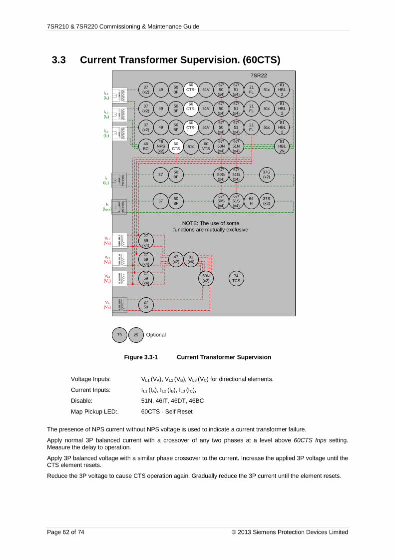
7SR210 & 7SR220 Commissioning & Maintenance Guide
Page 62 of 74 © 2013 Siemens Protection Devices Limited
3.3 Current Transformer Supervision. (60CTS)7SR22
46BC
46NPS(x2)
37(x2) 49 50
BF
VL1
(VA)
VL2
(VB)
VL3
(VC)
V4
(VX)
IL1
(IA)
81HBL
2
37(x2) 49 50
BFIL2
(IB)
81HBL
2
37(x2) 49 50
BFIL3
(IC)
81HBL
2
60CTS
I4(IG)
I5(ISEF)
74TCS
NOTE: The use of somefunctions are mutually exclusive
67/50
(x4)
67/51
(x4)
67/50N(x4)
67/50
(x4)
67/50
(x4)
67/51
(x4)
67/51
(x4)
67/51N(x4)
67/50G(x4)
67/51G(x4)
67/50S(x4)
67/51S(x4)
64H
2759
2759
(x4)
2759
(x4)
2759
(x4)
47(x2)
81(x6)
79 Optional
59N(x2)
81HBL2N
60VTS
51V
51V
51V
37G(x2)
37S(x2)
51c
60CTS-
I
60CTS-
I
60CTS-
I
37 50BF
37 50BF
25
21FL
21FL
21FL
51c
51c
51c
Figure 3.3-1 Current Transformer Supervision
Voltage Inputs: VL1 (VA), VL2 (VB), VL3 (VC) for directional elements.
Current Inputs: IL1 (IA), IL2 (IB), IL3 (IC),
Disable: 51N, 46IT, 46DT, 46BC
Map Pickup LED:. 60CTS - Self Reset
The presence of NPS current without NPS voltage is used to indicate a current transformer failure.
Apply normal 3P balanced current with a crossover of any two phases at a level above 60CTS Inps setting.Measure the delay to operation.
Apply 3P balanced voltage with a similar phase crossover to the current. Increase the applied 3P voltage until theCTS element resets.
Reduce the 3P voltage to cause CTS operation again. Gradually reduce the 3P current until the element resets.

7SR210 & 7SR220 Commissioning & Maintenance Guide
© 2013 Siemens Protection Devices Limited Page 63 of 74
Setting Measured
60CTS Delay
60CTS Inps
60CTS Vnps
3.3.1 ELEMENT BLOCKING
The CT Supervision function can be blocked by Binary Input Inhibit. This functionality should be checked.
Element BI Inhibits
60CTS
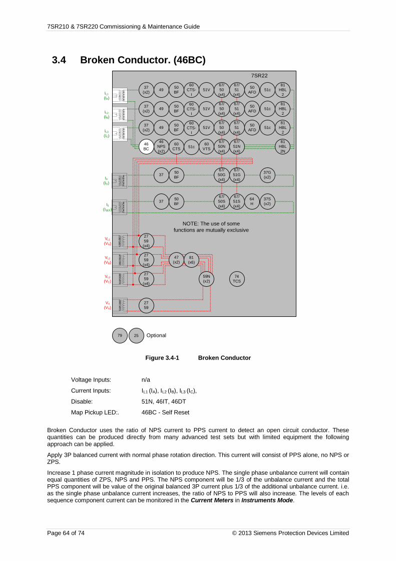
7SR210 & 7SR220 Commissioning & Maintenance Guide
Page 64 of 74 © 2013 Siemens Protection Devices Limited
3.4 Broken Conductor. (46BC)7SR22
46BC
46NPS(x2)
37(x2) 49 50
BF
VL1
(VA)
VL2
(VB)
VL3
(VC)
V4
(VX)
IL1
(IA)
81HBL
2
37(x2) 49 50
BFIL2
(IB)
81HBL
2
37(x2) 49 50
BFIL3
(IC)
81HBL
2
60CTS
I4(IG)
I5(ISEF)
74TCS
NOTE: The use of somefunctions are mutually exclusive
67/50
(x4)
67/51
(x4)
67/50N(x4)
67/50
(x4)
67/50
(x4)
67/51
(x4)
67/51
(x4)
67/51N(x4)
67/50G(x4)
67/51G(x4)
67/50S(x4)
67/51S(x4)
64H
2759
2759
(x4)
2759
(x4)
2759
(x4)
47(x2)
81(x6)
79 Optional
59N(x2)
81HBL2N
60VTS
51V
51V
51V
37G(x2)
37S(x2)
51c
60CTS-
I
60CTS-
I
60CTS-
I
37 50BF
37 50BF
25
50AFD
50AFD
50AFD
51c
51c
51c
Figure 3.4-1 Broken Conductor
Voltage Inputs: n/a
Current Inputs: IL1 (IA), IL2 (IB), IL3 (IC),
Disable: 51N, 46IT, 46DT
Map Pickup LED:. 46BC - Self Reset
Broken Conductor uses the ratio of NPS current to PPS current to detect an open circuit conductor. Thesequantities can be produced directly from many advanced test sets but with limited equipment the followingapproach can be applied.
Apply 3P balanced current with normal phase rotation direction. This current will consist of PPS alone, no NPS orZPS.
Increase 1 phase current magnitude in isolation to produce NPS. The single phase unbalance current will containequal quantities of ZPS, NPS and PPS. The NPS component will be 1/3 of the unbalance current and the totalPPS component will be value of the original balanced 3P current plus 1/3 of the additional unbalance current. i.e.as the single phase unbalance current increases, the ratio of NPS to PPS will also increase. The levels of eachsequence component current can be monitored in the Current Meters in Instruments Mode.

7SR210 & 7SR220 Commissioning & Maintenance Guide
© 2013 Siemens Protection Devices Limited Page 65 of 74
Inject 1 A of balanced current. Gradually increase imbalance current, operating level should be as follows:
46BC Setting1P unbalance current
(% of 3P current)
20% 75%
25% 100%
30% 129%
35% 161%
40% 200%
46BC Setting 3P balanced current (A) 1P unbalance current (A) Measured Unbalancecurrent
Apply 1 A 1P unbalance current without 3P balanced current. Measure 46BC operating time.
46BC Delay setting Measured
3.4.1 ELEMENT BLOCKING
The Broken Conductor element can be blocked by Binary Input Inhibit. This functionality should be checked.
Element BI Inhibits
46BC

7SR210 & 7SR220 Commissioning & Maintenance Guide
Page 66 of 74 © 2013 Siemens Protection Devices Limited
3.5 Load Blinder (21)7SR22
46BC
46NPS(x2)
37(x2) 49 50
BF
VL1
(VA)
VL2
(VB)
VL3
(VC)
V4
(VX)
IL1
(IA)
81HBL
2
37(x2) 49 50
BFIL2
(IB)
81HBL
2
37(x2) 49 50
BFIL3
(IC)
81HBL
2
60CTS
I4(IG)
I5(ISEF)
74TCS
NOTE: The use of somefunctions are mutually exclusive
67 / 50 /51( x 4)
67/50/51N( x 4)
67/50/51G( x 4)
67/50/51S( x 4)
64H
2759
2759
(x4)
2759
(x4)
2759
(x4)
47(x2)
81(x6)
79 Optional
59N(x2)
81HBL2N
60VTS
51V
51V
51V
37G(x2)
37S(x2)
51c
60CTS-
I
60CTS-
I
60CTS-
I
37 50BF
37 50BF
25
21LB
21LB
21LB
51c
51c
51c
50AFD
50AFD
50AFD
67 / 50 /51( x 4)
67 / 50 /51( x 4)
Figure 3.5-1 Load Blinder (21)
Voltage Inputs: VL1 (VA), VL2 (VB), VL3 (VC)
Current Inputs: IL1 (IA), IL2 (IB), IL3 (IC),
Disable: 51-n, 51V, 51c, 46, 49, 50BF, 79
Map Pickup LED: 21LB-3P, 21LB-1P - Self Reset
Load Blinders are designed to block Overcurrent elements from tripping in heavy load conditions.User settings 21LB-3P Angle and 21LB-3P Impedance allow user to define the Blinder region depending on thenetworks or specifically a line’s loading and fault limits.The calculated impedance can be: -
· In Blinder Region in which case the Load Blinder FWD or REV is active depending on if the impedance isin the 1st or 4th and/or 2nd or 3rd quadrant of the R-X plot respectively.
· In operate region in which case there is no active Load Blinder block and the Overcurrent elementoperates depending on additional factors.
· A 5 degree Hysteresis is allowed between operate and block zone.

7SR210 & 7SR220 Commissioning & Maintenance Guide
© 2013 Siemens Protection Devices Limited Page 67 of 74
The design of a Load Blinder 3Ph is based on the theory that protection blocking should be issued only duringdefinable allowable system power flow conditions i.e. an overcurrent blocking signal can only be issued when:
§ Positive Sequence Voltage Vpps is not significantly changed, when the Vpps is above the 21LB-3P VPPSSetting.AND
§ Negative Sequence Current Inps is lower than 21LB-3P INPS SettingAND
§ Distributed generators feed in PPS current into the system. In case of high load in system due todistributed generation hence resulting in change of Zpps.Zpps is calculated from Vpps and Ipps. The magnitude and angle of Zpps is compared with 21LB-3PImpedance and 21LB-3P Angle to determine if the impedance is in operate or block and/or FWD orREV zone.
+R
+X
PhaseFault
BlockZone
LoadImpedance
b
a
NominalImpedanceZ = 1p.u. =VL / (√3 x I)
c-R
-X
Vpps value Point 1Point 2
Point 3Point 4
0360
Trip LevelI = Vs / Z
OperateZone
a = 21LB-3P Impedancesettingb = 21LB-3P Angle +vesettingc = 21LB-3P Angle -vesetting
Point 6Point 5
BlockZone
LoadImpedance
ba
c
Point 7
Point 10Point 9
Point 8
Figure 3.5-2 Load Blinder (21) Boundary Points

7SR210 & 7SR220 Commissioning & Maintenance Guide
Page 68 of 74 © 2013 Siemens Protection Devices Limited
3.5.1 DETERMINING LOAD BLINDER REGIONS (21LB)
Test Procedure (Using Omicron Relay Test Set)1. Set-up the relay with default or appropriate parameter settings.2. Set-up Omicron current and voltage settings e.g. 63.5 V and 0.5 A three-phase.3. Select all three currents and set an appropriate initial angle for rotation on the Omicron.4. Apply Omicron current and voltage to the relay.
5. Using the PC mouse click the appropriate arrow ‘ ’ to rotate the angle of current in the anti-clockwise(positive degree) direction.
6. View the LEDs for indication of Load Blinder operation as the angle moves out-of or into the Load Blinderregion.
7. Rotating the angle in an anti-clockwise direction will see the LEDs extinguish, this indicates the drop-offpoint of the Load Blinder region. Record the angle as Point1 in the table of values.
8. Rotating the angle from this point in a clockwise direction will see the LEDs illuminate which indicates thepick-up point of the Load Blinder region. Record the angle as Point 2 in the table of values.
9. Continue this process to find the other boundaries. See Error! Reference source not found. below.
Angle data points (b and c) Default SettingsLoad Blinder
regionForward (+) Boundary Forward (-) Boundary
Angle = 20 (b) Angle = 340 (-20) (c)PU (Raised) DO (Reset) PU (Raised) DO (Reset)
Angle Point 2 Point 1 Point 3 Point 4
Angle limits (b and c). Typical values.Load Blinder
regionForward (+) Boundary Foreward (-) Boundary
Angle = 20 (b) Angle = 340 (-20) (c)PU (Raised) DO (Reset) PU (Raised) DO (Reset)
Angle 20 21 340 339

7SR210 & 7SR220 Commissioning & Maintenance Guide
© 2013 Siemens Protection Devices Limited Page 69 of 74
3.5.2 DETERMINING TRIP LEVEL
Test Procedure (Using Omicron Relay Test Set)1. Set-up the relay with default or appropriate parameter settings (see table below).2. Set-up Omicron current and voltage settings e.g. 63.5 V and 1.0 A three-phase.3. Select all three currents and set an appropriate initial current level for increase on the Omicron.4. Apply Omicron current and voltage to the relay.
5. Using the PC mouse click the appropriate arrow ‘ ’ to adjust current level.
6. View the LEDs for indication of Load Blinder operation as the current increases out-of the Load Blinderregion. This is the DO point 5.
7. View the LEDs for indication of Load Blinder operation as the current decreases into the Load Blinderregion. This is the PU point 6.
Trip Level I = Vs / Z Default SettingsParameters Setting DO PU
Impedance Ω 42Point 5 Point 6
Voltage V 63.5
Trip Level I = Vs / Z. Typical values.Parameters Setting DO PU
Impedance Ω 421.591 A 1.511 A
Voltage V 63.5

7SR210 & 7SR220 Commissioning & Maintenance Guide
Page 70 of 74 © 2013 Siemens Protection Devices Limited
3.6 Trip Circuit Supervision. (74TCS)7SR22
46BC
46NPS(x2)
37(x2) 49 50
BF
VL1
(VA)
VL2
(VB)
VL3
(VC)
V4
(VX)
IL1
(IA)
81HBL
2
37(x2) 49 50
BFIL2
(IB)
81HBL
2
37(x2) 49 50
BFIL3
(IC)
81HBL
2
60CTS
I4(IG)
I5(ISEF)
74TCS
NOTE: The use of somefunctions are mutually exclusive
67/50
(x4)
67/51
(x4)
67/50N(x4)
67/50
(x4)
67/50
(x4)
67/51
(x4)
67/51
(x4)
67/51N(x4)
67/50G(x4)
67/51G(x4)
67/50S(x4)
67/51S(x4)
64H
2759
2759
(x4)
2759
(x4)
2759
(x4)
47(x2)
81(x6)
79 Optional
59N(x2)
81HBL2N
60VTS
51V
51V
51V
37G(x2)
37S(x2)
51c
60CTS-
I
60CTS-
I
60CTS-
I
37 50BF
37 50BF
25
50AFD
50AFD
50AFD
51c
51c
51c
Figure 3.6-1 Trip Circuit Supervision
Voltage Inputs: n/a
Current Inputs: n/a
Disable:
Map Pickup LED: 74TCS-n - Self Reset
The TCS-n Delay can be initiated by applying an inversion to the relevant status input and measured bymonitoring of the alarm output.
TCS-n Delay setting Measured

7SR210 & 7SR220 Commissioning & Maintenance Guide
© 2013 Siemens Protection Devices Limited Page 71 of 74
3.7 Magnetising Inrush Detector. (81HBL)7SR22
46BC
46NPS(x2)
37(x2) 49 50
BF
VL1
(VA)
VL2
(VB)
VL3
(VC)
V4
(VX)
IL1
(IA)
81HBL
2
37(x2) 49 50
BFIL2
(IB)
81HBL
2
37(x2) 49 50
BFIL3
(IC)
81HBL
2
60CTS
I4(IG)
I5(ISEF)
74TCS
NOTE: The use of somefunctions are mutually exclusive
67/50
(x4)
67/51
(x4)
67/50N(x4)
67/50
(x4)
67/50
(x4)
67/51
(x4)
67/51
(x4)
67/51N(x4)
67/50G(x4)
67/51G(x4)
67/50S(x4)
67/51S(x4)
64H
2759
2759
(x4)
2759
(x4)
2759
(x4)
47(x2)
81(x6)
79 Optional
59N(x2)
81HBL2N
60VTS
51V
51V
51V
37G(x2)
37S(x2)
51c
60CTS-
I
60CTS-
I
60CTS-
I
37 50BF
37 50BF
25
50AFD
50AFD
50AFD
51c
51c
51c
Figure 3.7-1 Magnetising Inrush Detector
Voltage Inputs: n/a
Current Inputs: IL1 (IA), IL2 (IB), IL3 (IC),
Disable:
Map Pickup LED:
Logical operation of the harmonic blocking can be tested by current injection at 100 Hz to cause operation of theblocking signals.
7SR210 & 7SR220 Commissioning & Maintenance Guide
Page 72 of 74 © 2013 Siemens Protection Devices Limited
Section 4: Control & Logic Functions
4.1 Autoreclose (79)Autoreclose sequences can be specified differently for Phase. Earth, Externally Initiated and SEF faults.Sequences should be simulated for each applicable different fault type with the actual relay settings required forservice installed in the relay.
The relay requires that the correct indications are received at the CB auxiliary contact inputs and that the injectedcurrent and voltage used to generate protection operations are timed to the autoreclose sequence to provide arealistic simulation of the actual system conditions.
The Instruments Menu contains Autoreclose Meters for the Autoreclose State and the Shot No. which are usefulduring sequence testing.
The time stamped Events listing can be downloaded from the relay to a pc to allow diagnosis of the sequenceincluding measurements of sequence Dead Times and other timing without the use of external measuringequipment or complex connections.
4.2 Quick LogicIf this functionality is used, the logic equations may interfere with testing of other protection functions in the relay.The function of the Quick Logic equations should be tested conjunctively with connected plant or by simulation toassess suitability and check for correct operation on an individual basis with tests specifically devised to suit theparticular application.

7SR210 & 7SR220 Commissioning & Maintenance Guide
© 2013 Siemens Protection Devices Limited Page 73 of 74
Section 5: Testing and Maintenance7SR21 & 7SR22 relays are maintenance free, with no user serviceable parts.
5.1 Periodic TestsDuring the life of the relay, it should be checked for operation during the normal maintenance period for the siteon which the product is installed. It is recommended the following tests are carried out: -
Visual inspection of the metering display.1. Operation of output contacts2. Secondary injection of each element
5.2 MaintenanceRelay failure will be indicated by the ‘Protection Healthy’ LED being off or flashing. A message may also bedisplayed on the LCD. In the event of failure Siemens Protection Devices Ltd. (or one of its agents) should becontacted – see defect report sheet in section 5.3.
The relay should be returned as a complete unit. No attempt should be made to disassemble the unit to isolateand return only the damaged sub-assembly. It may however be convenient to fit the withdrawable relay to theouter case from a spare relay, to avoid the disturbance of relay panel wiring, for return to Siemens ProtectionDevices Ltd. The withdrawable relay should never be transported without the protection of the outer case.

7SR210 & 7SR220 Commissioning & Maintenance Guide
Page 74 of 74 © 2013 Siemens Protection Devices Limited
5.3 TroubleshootingTable 5-1 Troubleshooting Guide
Observation ActionRelay does not power up. Check that the correct auxiliary DC voltage is applied and that the
polarity is correct.Relay won’t accept the password. The Password being entered is wrong. Enter correct password.
If correct password has been forgotten, note down the NumericCode which is displayed at the Change Password screen e.g.
To retrieve the password, communicate this code to a SiemensProtection Devices Ltd. representative.
Protection Healthy LED flashes General failure. Contact a Siemens Protection Devices Ltd.representative.
LCD screen flashes continuously. The LCD has many possible error messages which whendisplayed will flash continuously. These indicate various processorcard faults.General failure. Contact a Siemens Protection Devices Ltd.representative.
Backlight is on but no text can be seen. Adjust the contrast.Scrolling text messages are unreadable. Adjust the contrast.Relay displays one instrument afteranother with no user intervention.
This is normal operation, default instruments are enabled.Remove all instruments from the default list and only add thosethat are required.
Cannot communicate with the relay. Check that all of the communications settings match those usedby Reydisp Evolution.Check that the Tx and Rx fibre-optic cables are connectedcorrectly. (Tx –> Rx and Rx –> Tx).Check that all cables, modems and fibre-optic cables workcorrectly.Ensure that IEC 60870-5-103 is specified for the connected port(COM1, COM2, COM3 or COM4).
Relays will not communicate in a ringnetwork.
Check that the Data Echo setting on all relays is set to ON.Check that all relays are powered up.Check that all relays have unique addresses.
Status inputs do not work. Check that the correct DC voltage is applied and that the polarityis correct.Check that the status input settings such as the pick-up and drop-off timers and the status inversion function are correctly set.
Relay instrument displays show smallcurrents or voltages even though thesystem is dead.
This is normal. The relay is displaying calculation noise. This willnot affect any accuracy claims for the relay.
If the above checklist does not help in correcting the problem please contact the local Siemens office or contactPTD 24hr Customer Support, Tel: +49 180 524 7000, Fax: +49 180 524 2471, e-mail:[email protected].
Change password = 1234567

The copyright and other intellectual property rights in this document, and in any model or article produced from it(and including any registered or unregistered design rights) are the property of Siemens Protection DevicesLimited. No part of this document shall be reproduced or modified or stored in another form, in any data retrievalsystem, without the permission of Siemens Protection Devices Limited, nor shall any model or article bereproduced from this document unless Siemens Protection Devices Limited consent.
While the information and guidance given in this document is believed to be correct, no liability shall be acceptedfor any loss or damage caused by any error or omission, whether such error or omission is the result ofnegligence or any other cause. Any and all such liability is disclaimed.
© 2013 Siemens Protection Devices Limited
7SR210 Non-Directional Relay
7SR220 Directional Relay
Applications Guide

7SR210 & 7SR220 Applications Guide
Page 2 of 46 © 2013 Siemens Protection Devices Limited
Document Release History
This document is issue 2015/06.
2011/05 First issue
2013/01 Typographical revisions and added data. Updated in line with software release.
2014/06 Typographical revisions and added data. Updated in line with software release.
2015/06 Typographical revisions and added data. Updated in line with software release.
Software Revision History2011/05 2435H85008R7a-7a (7SR210)
2435H85009R7a-7a (7SR220)
First Release
2013/01 2435H85008R7c-7b (7SR210)
2435H85009R7c-7b (7SR220)
Introduced journaling file system.Added 61850 logical nodes for CB Counters, metering, 50BF,46BC, 81HBL2 and line check.Added Line Check on non-AR devices.Added 74CCS Close Circuit Supervision.
2014/06 2435H85008R7f-7d (7SR210)
2435H85009R7f-7d (7SR220)
Added Fault Locator feature and Check Sync feature.Fault data transmitted over 103.Additional communications data, control features, meters.
2015/06 2435H85008R8a-7f (7SR210)
2435H85009R8a-7f (7SR220)
Added Power Factor Meters, Load Blinding feature, Arc FlashDetector. Over current TM Setting Range extended.

7SR210 & 7SR220 Applications Guide
© 2013 Siemens Protection Devices Limited Page 3 of 46
ContentsDocument Release History ............................................................................................................... 2Software Revision History ................................................................................................................ 2Section 1: Common Functions ......................................................................................................... 5
1.1 Multiple Settings Groups ...................................................................................................... 51.2 Binary Inputs ........................................................................................................................ 61.3 Binary Outputs ..................................................................................................................... 91.4 LEDs .................................................................................................................................... 9
Section 2: Protection Functions ..................................................................................................... 112.1 Time delayed overcurrent (51/51G/51N) ............................................................................. 11
2.1.1 Selection of Overcurrent Characteristics................................................................. 122.1.2 Reset Delay ........................................................................................................... 13
2.2 Voltage dependent overcurrent (51V) ................................................................................. 142.3 Cold Load Settings (51c) .................................................................................................... 142.4 Instantaneous Overcurrent (50/50G/50N) ........................................................................... 15
2.4.1 Blocked Overcurrent Protection Schemes .............................................................. 152.5 Sensitive Earth-fault Protection (50SEF) ............................................................................. 172.6 Directional Protection (67) .................................................................................................. 182.7 Directional Earth-Fault (50/51G, 50/51N, 51/51SEF)........................................................... 212.8 High Impedance Restricted Earth Fault Protection (64H) .................................................... 222.9 Negative Phase Sequence Overcurrent (46NPS)................................................................ 242.10 Undercurrent (37) ............................................................................................................... 242.11 Thermal Overload (49) ....................................................................................................... 242.12 Under/Over Voltage Protection (27/59) ............................................................................... 252.13 Neutral Overvoltage (59N) .................................................................................................. 26
2.13.1 Application with Capacitor Cone Units .................................................................... 272.13.2 Derived NVD Voltage ............................................................................................. 27
2.14 Negative Phase Sequence Overvoltage (47) ...................................................................... 272.15 Under/Over Frequency (81) ................................................................................................ 28
Section 3: CT Requirements ........................................................................................................... 293.1 CT Requirements for Overcurrent and Earth Fault Protection ............................................. 29
3.1.1 Overcurrent Protection CTs .................................................................................... 293.1.2 Earth Fault Protection CTs ..................................................................................... 29
3.2 CT Requirements for High Impedance Restricted Earth Fault Protection ............................. 29
Section 4: Control Functions.......................................................................................................... 304.1 Auto-reclose Applications ................................................................................................... 30
4.1.1 Auto-Reclose Example 1 ........................................................................................ 314.1.2 Auto-Reclose Example 2 (Use of Quicklogic with AR) ............................................ 32
4.2 Quick Logic Applications .................................................................................................... 334.2.1 Auto-Changeover Scheme Example ...................................................................... 33
Section 5: Supervision Functions .................................................................................................. 345.1 Circuit-Breaker Fail (50BF) ................................................................................................. 34
5.1.1 Settings Guidelines ................................................................................................ 345.2 Current Transformer Supervision (60CTS).......................................................................... 365.3 Voltage Transformer Supervision (60VTS).......................................................................... 375.4 Trip-Circuit Supervision (74TCS) ........................................................................................ 38
5.4.1 Trip Circuit Supervision Connections ...................................................................... 385.5 Inrush Detector (81HBL2) ................................................................................................... 405.6 Broken Conductor / Load Imbalance (46BC) ....................................................................... 405.7 Circuit-Breaker Maintenance .............................................................................................. 40
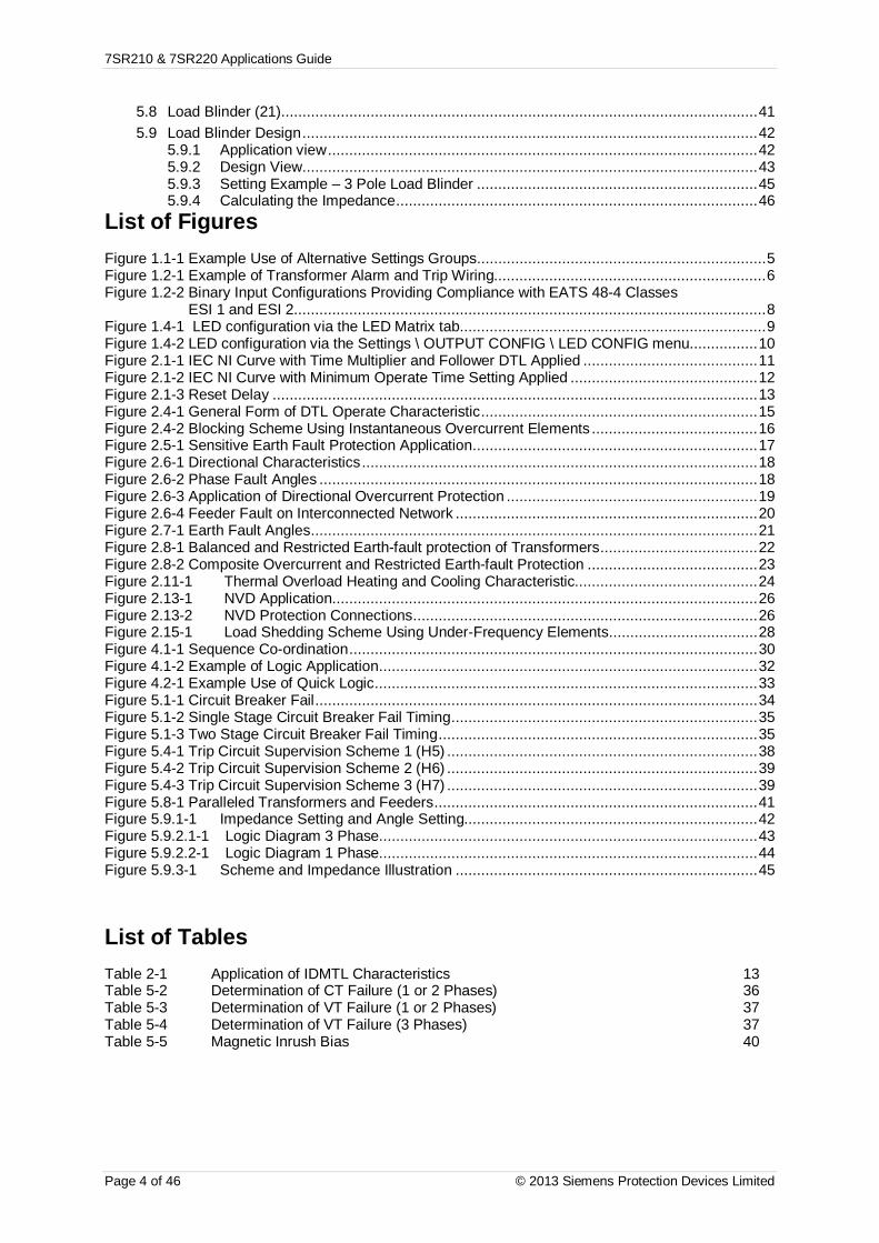
7SR210 & 7SR220 Applications Guide
Page 4 of 46 © 2013 Siemens Protection Devices Limited
5.8 Load Blinder (21)................................................................................................................ 415.9 Load Blinder Design ........................................................................................................... 42
5.9.1 Application view ..................................................................................................... 425.9.2 Design View........................................................................................................... 435.9.3 Setting Example – 3 Pole Load Blinder .................................................................. 455.9.4 Calculating the Impedance ..................................................................................... 46
List of FiguresFigure 1.1-1 Example Use of Alternative Settings Groups.................................................................... 5Figure 1.2-1 Example of Transformer Alarm and Trip Wiring................................................................ 6Figure 1.2-2 Binary Input Configurations Providing Compliance with EATS 48-4 Classes
ESI 1 and ESI 2 ............................................................................................................... 8Figure 1.4-1 LED configuration via the LED Matrix tab ........................................................................ 9Figure 1.4-2 LED configuration via the Settings \ OUTPUT CONFIG \ LED CONFIG menu................ 10Figure 2.1-1 IEC NI Curve with Time Multiplier and Follower DTL Applied ......................................... 11Figure 2.1-2 IEC NI Curve with Minimum Operate Time Setting Applied ............................................ 12Figure 2.1-3 Reset Delay .................................................................................................................. 13Figure 2.4-1 General Form of DTL Operate Characteristic ................................................................. 15Figure 2.4-2 Blocking Scheme Using Instantaneous Overcurrent Elements ....................................... 16Figure 2.5-1 Sensitive Earth Fault Protection Application ................................................................... 17Figure 2.6-1 Directional Characteristics ............................................................................................. 18Figure 2.6-2 Phase Fault Angles ....................................................................................................... 18Figure 2.6-3 Application of Directional Overcurrent Protection ........................................................... 19Figure 2.6-4 Feeder Fault on Interconnected Network ....................................................................... 20Figure 2.7-1 Earth Fault Angles ......................................................................................................... 21Figure 2.8-1 Balanced and Restricted Earth-fault protection of Transformers ..................................... 22Figure 2.8-2 Composite Overcurrent and Restricted Earth-fault Protection ........................................ 23Figure 2.11-1 Thermal Overload Heating and Cooling Characteristic........................................... 24Figure 2.13-1 NVD Application .................................................................................................... 26Figure 2.13-2 NVD Protection Connections ................................................................................. 26Figure 2.15-1 Load Shedding Scheme Using Under-Frequency Elements................................... 28Figure 4.1-1 Sequence Co-ordination ................................................................................................ 30Figure 4.1-2 Example of Logic Application ......................................................................................... 32Figure 4.2-1 Example Use of Quick Logic .......................................................................................... 33Figure 5.1-1 Circuit Breaker Fail ........................................................................................................ 34Figure 5.1-2 Single Stage Circuit Breaker Fail Timing ........................................................................ 35Figure 5.1-3 Two Stage Circuit Breaker Fail Timing ........................................................................... 35Figure 5.4-1 Trip Circuit Supervision Scheme 1 (H5) ......................................................................... 38Figure 5.4-2 Trip Circuit Supervision Scheme 2 (H6) ......................................................................... 39Figure 5.4-3 Trip Circuit Supervision Scheme 3 (H7) ......................................................................... 39Figure 5.8-1 Paralleled Transformers and Feeders ............................................................................ 41Figure 5.9.1-1 Impedance Setting and Angle Setting..................................................................... 42Figure 5.9.2.1-1 Logic Diagram 3 Phase......................................................................................... 43Figure 5.9.2.2-1 Logic Diagram 1 Phase......................................................................................... 44Figure 5.9.3-1 Scheme and Impedance Illustration ....................................................................... 45
List of TablesTable 2-1 Application of IDMTL Characteristics 13Table 5-2 Determination of CT Failure (1 or 2 Phases) 36Table 5-3 Determination of VT Failure (1 or 2 Phases) 37Table 5-4 Determination of VT Failure (3 Phases) 37Table 5-5 Magnetic Inrush Bias 40

7SR210 & 7SR220 Applications Guide
© 2013 Siemens Protection Devices Limited Page 5 of 46
Section 1: Common Functions1.1 Multiple Settings GroupsAlternate settings groups can be used to reconfigure the relay during significant changes to system conditionse.g.
Primary plant switching in/out.
Summer/winter or day/night settings.
switchable earthing connections.
Loss of Grid connection (see below)
Figure 1.1-1 Example Use of Alternative Settings Groups
RADIAL SUBSTATION
Startgenerators
Select alternatesettings group
LocalGeneration
Industrial system draws power from gridsystem during normal operation
Relays normally use settings group 1
On loss of mains:Local generation switched in.Non essential loads trippedRelays on essential circuits switched tosettings group 2 to reflect new load andfault currents
Non-essentialloads
Trip non-essential loads

7SR210 & 7SR220 Applications Guide
Page 6 of 46 ©2015 Siemens Protection Devices Limited
1.2 Binary InputsEach Binary Input (BI) can be programmed to operate one or more of the relay functions, LEDs or output relays.These could be used to bring such digital signals as Inhibits for protection elements, the trip circuit supervisionstatus, autoreclose control signals etc. into the Relay.
Alarm and Tripping Inputs
A common use of binary inputs is to provide indication of alarm or fault conditions e.g. transformer Buchholz Gasor Buchholz Surge conditions. The Binary Inputs are mapped to LED(s), waveform storage trigger and binaryoutputs. Note that transformer outputs which require high speed tripping, such as a Buchholz Surge, should bewired to a binary input to provide LED indication and also have a parallel connection wired to directly trip thecircuit via a blocking diode, see fig. 1.2-1:
Figure 1.2-1 Example of Transformer Alarm and Trip Wiring

7SR210 & 7SR220 Applications Guide
© 2013 Siemens Protection Devices Limited Page 7 of 46
The Effects of Capacitance Current
The binary inputs have a low minimum operate current and may be set for instantaneous operation. Considerationshould be given to the likelihood of mal-operation due to capacitance current. Capacitance current can flowthrough the BI for example if an earth fault occurs on the dc circuits associated with the relay. The binary inputswill be less likely to mal-operate if they:
1 Have both the positive and negative switched (double-pole switched).
2 Do not have extensive external wiring associated with them e.g. if the wiring is confined to therelay room.
Where a binary input is both used to influence a control function (e.g. provide a tripping function) and it isconsidered to be susceptible to mal-operation the external circuitry can be modified to provide immunity to suchdisturbances, see fig 1.2-2.
AC Rejection
The default pick-up time delay of 20 ms provides immunity to ac current e.g. induced from cross site wiring.

7SR210 & 7SR220 Applications Guide
Page 8 of 46 ©2015 Siemens Protection Devices Limited
2K0
BI (19 V)
ESI-1 30 V DC Nominal(24 V to 37.5 V Operative)
IOP > 10 mA470
1K5
48 V DC Nominal(37.5 V to 60 V Operative)
IOP > 10 mA1K6
1K5
110 V DC Nominal(87.5 V to 137.5 V
Operative)IOP > 25 mA
560
ESI-2 30 V DC Nominal(24 V to 37.5 V Operative)
IOP > 20 mA220
820
48 V DC Nominal(37.5 V to 60 V Operative)
IOP > 20 mA820
820
110 V DC Nominal(87.5 V to 137.5 V
Operative)IOP > 50 mA
1K2
330
BI DTL = 10 ms(10 µF, 60 V Capacitance discharge)
BI DTL = 10 ms(10 µF, 150 V Capacitance discharge)
BI (19 V)
BI (19 V)
BI (19 V)
BI (19 V)
BI (19 V)
+
-
+
+
+
+
+
-
-
-
-
-
Resistor power ratings: 30 V DC Nominal >3 W48 V DC Nominal >3 W110 V DC Nominal >10 W (ESI-1)110 V DC Nominal >20 W (ESI-2)
Resistors must be wired with crimped connections as they may run hot
110 V DC Nominal(87.5 V to 137.5 V
Operative)IOP > 25 mA
2K7
110 V DC Nominal(87.5 V to 137.5 V
Operative)IOP > 50 mA
1K3
BI DTL = 10 ms(10 µF, 150 V Capacitance discharge)
BI (88 V) BI (88 V)
+ +
- -
Figure 1.2-2 Binary Input Configurations Providing Compliance with EATS 48-4 Classes ESI 1 and ESI 2

7SR210 & 7SR220 Applications Guide
© 2013 Siemens Protection Devices Limited Page 9 of 46
1.3 Binary OutputsBinary Outputs are mapped to output functions by means of settings. These could be used to bring out suchdigital signals as trips, a general pick-up, plant control signals etc.
All Binary Outputs are Trip rated
Each can be defined as Self or Hand Reset. Self-reset contacts are applicable to most protection applications.Hand-reset contacts are used where the output must remain active until the user expressly clears it e.g. in acontrol scheme where the output must remain active until some external feature has correctly processed it.
Case contacts 26 and 27 will automatically short-circuit when the relay is withdrawn from the case. This can beused to provide an alarm that the Relay is out of service.
Notes on Self Reset Outputs
With a failed breaker condition the relay may remain operated until current flow in the primary system isinterrupted by an upstream device. The relay will then reset and attempt to interrupt trip coil current flowingthrough an output contact. Where this level is above the break rating of the output contact an auxiliary relay withheavy-duty contacts should be utilised.
1.4 LEDsOutput-function LEDs are mapped to output functions by means of settings. These could be used to display suchdigital signals as trips, a general pick-up, plant control signals etc.
User Defined Function Key LEDs are used to indicate the status of Function Key operation. These do not relatedirectly to the operation of the Function Key but rather to its consequences. If a Function Key is depressed toclose a Circuit-Breaker, the associated LED would show the status of the Circuit-Breaker closed Binary Input.
Each LED can be defined as Self or Hand Reset. Hand reset LEDs are used where the user is required toexpressly acknowledge the change in status e.g. critical operations such as trips or system failures. Self-resetLEDs are used to display features which routinely change state, such as Circuit-Breaker open or close.
The status of hand reset LEDs is retained in capacitor-backed memory in the event of supply loss.
Each LED can be assigned as red, yellow or green in colour. There are two methods for doing this: -
1) In the LED Matrix tab, to assign the LED as a red colour select a box on the red row. To assign theLED as a green colour select a box on the green row. To assign the LED as a yellow colour, selectboxes on both the red and green rows.
NB: If there are no boxes selected the LED will not illuminate.
Figure 1.4-1 LED configuration via the LED Matrix tab

7SR210 & 7SR220 Applications Guide
Page 10 of 46 ©2015 Siemens Protection Devices Limited
In the OUTPUT CONFIG\LED CONFIG menu in the Settings tab, to assign the required LED as aparticular colour, either red or green, type the LED number in the appropriate row. To assign therequired LED as a yellow colour, type the LED number in both red and green rows.
NB: If a LED number is not assigned that particular LED will not illuminate.
Figure 1.4-2 LED configuration via the Settings \ OUTPUT CONFIG \ LED CONFIG menu

7SR210 & 7SR220 Applications Guide
© 2013 Siemens Protection Devices Limited Page 11 of 46
Section 2: Protection Functions
2.1 Time delayed overcurrent (51/51G/51N)The 51-n characteristic element provides a number of time/current operate characteristics. The element can bedefined as either an Inverse Definite Minimum Time Lag (IDMTL) or Definite Time Lag (DTL) characteristic. If anIDMTL characteristic is required, then IEC, ANSI/IEEE and a number of manufacturer specific curves aresupported.
IDMTL characteristics are defined as “Inverse” because their tripping times are inversely proportional to the FaultCurrent being measured. This makes them particularly suitable to grading studies where it is important that onlythe Relay(s) closest to the fault operate. Discrimination can be achieved with minimised operating times.
To optimise the grading capability of the relay additional time multiplier, ‘Follower DTL’ (Fig. 2.1-1) or ‘MinimumOperate Time’ (Fig. 2.1-2) settings can be applied.
0.01
0.10
1.00
10.00
100.00
1000.00
1 10 100 1000
Current (x Is)
Ope
ratin
gTi
me
(Sec
onds
)
0.01
0.10
1.00
10.00
100.00
1000.00
1 10 100 1000
Current (x Is)
Ope
ratin
gTi
me
(Sec
onds
)
Figure 2.1-1 IEC NI Curve with Time Multiplier and Follower DTL Applied

7SR210 & 7SR220 Applications Guide
Page 12 of 46 ©2015 Siemens Protection Devices Limited
IEC NI Curve: TM = 1
Min Operate Time = 4sec
0.01
0.10
1.00
10.00
100.00
1000.00
1 10 100 1000
Current (x Is)
Ope
ratin
gTi
me
(Sec
onds
)
OPERATEZONE
Figure 2.1-2 IEC NI Curve with Minimum Operate Time Setting Applied
To increase sensitivity, dedicated Earth fault elements are used. There should be little or no current flowing toearth in a healthy system so such relays can be given far lower pick-up levels than relays which detect excesscurrent ( > load current) in each phase conductor. Such dedicated earth fault relays are important where the faultpath to earth is a high-resistance one (such as in highly arid areas) or where the system uses high values ofearthing resistor / reactance and the fault current detected in the phase conductors will be limited.
2.1.1 Selection of Overcurrent CharacteristicsEach pole has two independent over-current characteristics. Where required the two curves can be used:
To produce a composite curve
To provide a two stage tripping scheme
Where one curve is to be directionalised in the forward direction the other in the reverse direction.
The characteristic curve shape is selected to be the same type as the other relays on the same circuit or to gradewith items of plant e.g. fuses or earthing resistors.
The application of IDMTL characteristic is summarised in the following table:
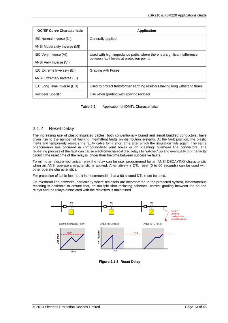
7SR210 & 7SR220 Applications Guide
© 2013 Siemens Protection Devices Limited Page 13 of 46
OC/EF Curve Characteristic Application
IEC Normal Inverse (NI)
ANSI Moderately Inverse (MI)
Generally applied
IEC Very Inverse (VI)
ANSI Very Inverse (VI)
Used with high impedance paths where there is a significant differencebetween fault levels at protection points
IEC Extreme Inversely (EI)
ANSI Extremely Inverse (EI)
Grading with Fuses
IEC Long Time Inverse (LTI) Used to protect transformer earthing resistors having long withstand times
Recloser Specific Use when grading with specific recloser
Table 2-1 Application of IDMTL Characteristics
2.1.2 Reset DelayThe increasing use of plastic insulated cables, both conventionally buried and aerial bundled conductors, havegiven rise to the number of flashing intermittent faults on distribution systems. At the fault position, the plasticmelts and temporarily reseals the faulty cable for a short time after which the insulation fails again. The samephenomenon has occurred in compound-filled joint boxes or on ‘clashing’ overhead line conductors. Therepeating process of the fault can cause electromechanical disc relays to “ratchet” up and eventually trip the faultycircuit if the reset time of the relay is longer than the time between successive faults.
To mimic an electromechanical relay the relay can be user programmed for an ANSI DECAYING characteristicwhen an ANSI operate characteristic is applied. Alternatively a DTL reset (0 to 60 seconds) can be used withother operate characteristics.
For protection of cable feeders, it is recommended that a 60 second DTL reset be used.
On overhead line networks, particularly where reclosers are incorporated in the protected system, instantaneousresetting is desirable to ensure that, on multiple shot reclosing schemes, correct grading between the sourcerelays and the relays associated with the reclosers is maintained.
FAULTClashingconductors orre-sealing cable
R1R2R3
Electro-mechanical Relay
Time
TRIP
Argus (Inst. Reset)
Time
Argus (DTL Reset)
TRIP
Figure 2.1-3 Reset Delay

7SR210 & 7SR220 Applications Guide
Page 14 of 46 ©2015 Siemens Protection Devices Limited
2.2 Voltage dependent overcurrent (51V)Reduced voltage can indicate a fault on the system, it can be used to make the 51 elements more sensitive.
Typically Voltage Dependent Over-current (51V) is applied to:
Transformer Incomers: Where the impedance of the transformer limits fault current the measuredvoltage level can be used to discriminate between load and fault current.
Long lines: Where the impedance of the line limits fault current the measured voltage level can be usedto discriminate between load and fault current.
Generator circuits: When a Generator is subjected to a short circuit close to its terminals the short-circuit current follows a complex profile. After the initial "sub-transient" value, generally in the order of 7to 10 times full load current, it falls rapidly (around 10 ms to 20 ms) to the "transient" value. This is stillabout 5 to 7 times full load and would be sufficient to operate the protection's over-current elements.However the effect on armature reactance of the highly inductive short-circuit current is to increasesignificantly the internal impedance to the synchronous reactance value. If the Automatic VoltageRegulation (AVR) system does not respond to increase the excitation, the fault current will decay overthe next few seconds to a value below the full load current. This is termed the steady state fault current,determined by the Generator's synchronous reactance (and pre-fault excitation). It will be insufficient tooperate the protection's over-current elements and the fault will not be detected. Even if AVR is active,problems may still be encountered. The AVR will have a declared minimum sustained fault current andthis must be above the protection over-current settings. Close-in short circuit faults may also cause theAVR to reach its safety limits for supplying maximum excitation boost, in the order of several seconds,and this will result in AVR internal protection devices such as diode fuses to start operating. Thegenerator excitation will then collapse, and the situation will be the same as when no AVR was present.The fault may again not be detected.
Current grading remains important since a significant voltage reduction may be seen for faults on other parts ofthe system. An inverse time operating characteristic must therefore be used.
The VDO Level - the voltage setting below which the more sensitive operating curve applies - must be set lowenough to discriminate between short-circuits and temporary voltage dips due to overloads. However, it must alsobe high enough to cover a range of voltage drops for different circuit configurations, from around 0.6Vn to almostzero. Typically it will be set in the range 0.6 to 0.8Vn.
2.3 Cold Load Settings (51c)Once a Circuit-Breaker has been open for a period of time ed, higher than normal levels of load current may flowfollowing CB re-closure e.g. heating or refrigeration plant. The size and duration of this current is dependent uponthe type of load and the time that the CB is open.
The feature allows the relay to use alternative Shaped Overcurrent (51c) settings when a Cold Load condition isidentified. The cold load current and time multiplier settings will normally be set higher than those of the normalovercurrent settings.
The relay will revert to its usual settings (51-n) after elapse of the cold load period. This is determined either by auser set delay, or by the current in all 3-phases falling below a set level (usually related to normal load levels) fora user set period.

7SR210 & 7SR220 Applications Guide
© 2013 Siemens Protection Devices Limited Page 15 of 46
2.4 Instantaneous Overcurrent (50/50G/50N)Each instantaneous element has an independent setting for pick-up current and a follower definite time lag (DTL)which can be used to provide time grading margins, sequence co-ordination grading or scheme logic. The“instantaneous” description relates to the pick-up of the element rather than its operation.
Ope
ratin
gtim
e
Figure 2.4-1 General Form of DTL Operate Characteristic
Instantaneous elements can be used in current graded schemes where there is a significant difference betweenthe fault current levels at different relay point. The Instantaneous element is set to pick up at a current level abovethe maximum Fault Current level at the next downstream relay location, and below its own fault current level. Theprotection is set to operate instantaneously and is often termed ‘Highset Overcurrent’. A typical application is theprotection of transformer HV connections – the impedance of the transformer ensuring that the LV side has amuch lower level of fault current.
The 50-n elements have a very low transient overreach i.e. their accuracy is not appreciably affected by the initialdc offset transient associated with fault inception.
2.4.1 Blocked Overcurrent Protection SchemesA combination of instantaneous and DTL elements can be used in blocked overcurrent protection schemes.These protection schemes are applied to protect substation busbars or interconnectors etc. Blocked overcurrentprotection provides improved fault clearance times when compared against normally graded overcurrent relays.
The blocked overcurrent scheme of busbar protection shown in Figure 2.4-2 illustrates that circuit overcurrent andearth fault protection relays can additionally be configured with busbar protection logic.
The diagram shows a substation. The relay on the incomer is to trip for busbar faults (F1) but remain inoperativefor circuit faults (F2).
In this example the overcurrent and earth fault settings for the incomer 50-1 element are set to below the relevantbusbar fault levels. 50-1 time delay is set longer than it would take to acknowledge receipt of a blocking signalfrom an outgoing circuit.
Close up faults on the outgoing circuits will have a similar fault level to busbar faults. As the incomer 50-1elements would operate for these faults it is necessary to provide a blocking output from the circuit protections.The 50-1 elements of the output relays are given lower current settings than the incomer 50-1 settings, the timedelay is set to 0ms. The output is mapped to a contact. The outgoing relay blocking contacts of all circuits arewired in parallel and this wiring is also connected to a BI on the incomer relay. The BI on the incomer relay ismapped to block its 50-1 element.

7SR210 & 7SR220 Applications Guide
Page 16 of 46 ©2015 Siemens Protection Devices Limited
Figure 2.4-2 Blocking Scheme Using Instantaneous Overcurrent Elements
Typically a time delay as low as 50 ms on the incomer 50-1 element will ensure that the incomer is not tripped foroutgoing circuit faults. However, to include for both equipment tolerances and a safety margin a minimum timedelay of 100 ms is recommended.
This type of scheme is very cost effective and provides a compromise between back-up overcurrent busbarprotection and dedicated schemes of busbar protection.
Instantaneous elements are also commonly applied to autoreclose schemes to grade with downstream circuitreclosers and maximise the probability of a successful auto-reclose sequence – see section 4.

7SR210 & 7SR220 Applications Guide
© 2013 Siemens Protection Devices Limited Page 17 of 46
2.5 Sensitive Earth-fault Protection (50SEF)Earth fault protection is based on the assumption that fault current levels will be limited only by the earth faultimpedance of the line and associated plant. However, it may be difficult to make an effective short circuit to earthdue to the nature of the terrain e.g. dry earth, desert or mountains. The resulting earth fault current may thereforebe limited to very low levels.
Sensitive earth fault (SEF) protection is used to detect such faults. The RM range of relays have a low burden, soavoiding unacceptable loading of the CTs at low current settings.SEF provides a backup to the main protection. A DTL characteristic with a time delay of several seconds istypically applied ensuring no interference with other discriminative protections. A relatively long time delay can betolerated since fault current is low and it is impractical to grade SEF protection with other earth fault protections.Although not suitable for grading with other forms of protection SEF relays may be graded with each other.
Where very sensitive current settings are required then it is preferable to use a core balance CT rather than wireinto the residual connection of the line CTs. The turns ratio of a core balance CT can be much smaller than that ofphase conductors as they are not related to the rated current of the protected circuit. Since only one core is used,the CT magnetising current losses are also reduced by a factor of 3.
Figure 2.5-1 Sensitive Earth Fault Protection Application
There are limits to how sensitive an SEF relay may be set since the setting must be above any line chargingcurrent levels that can be detected by the relay. On occurrence of an out of zone earth fault e.g. on circuit 3 theelevation of sound phase voltage to earth in a non-effectively earthed system can result in a zero sequencecurrent of up 3 times phase charging current flowing through the relay location.
The step change from balanced 3-phase charging currents to this level of zero sequence current includestransients. It is recommended to allow for a transient factor of 2 to 3 when determining the limit of chargingcurrent. Based on the above considerations the minimum setting of a relay in a resistance earthed power systemis 6 to 9 times the charging current per phase.

7SR210 & 7SR220 Applications Guide
Page 18 of 46 ©2015 Siemens Protection Devices Limited
2.6 Directional Protection (67)Each overcurrent stage can operate for faults in either forward or reverse direction. Convention dictates thatforward direction refers to power flow away from the busbar, while reverse direction refers to power flowingtowards the busbar.
The directional phase fault elements, 67/50 and 67/51, work with a Quadrature Connection to prevent loss ofpolarising quantity for close-in phase faults. That is, each of the current elements is directionalised by a voltagederived from the other two phases.
This connection introduces a 90° Phase Shift (Current leading Voltage) between reference and operate quantitieswhich must be allowed for in the Characteristic Angle setting. This is the expected fault angle, sometimes termedthe Maximum Torque Angle (MTA) as an analogy to older Electro-mechanical type relays
Example: Expected fault angle is -30º (Current lagging Voltage) so set Directional Angle to: +90° -30° = +60°.
A fault is determined to be in the selected direction if its phase relationship lies within a quadrant +/- 85° eitherside of the Characteristic Angle setting.
Figure 2.6-1 Directional Characteristics
A number of studies have been made to determine the optimum MTA settings e.g. W.K Sonnemann’s paper “AStudy of Directional Element Connections for Phase Relays”. Figure 2.6-2 shows the most likely fault angle forphase faults on Overhead Line and Cable circuits.
Figure 2.6-2 Phase Fault Angles
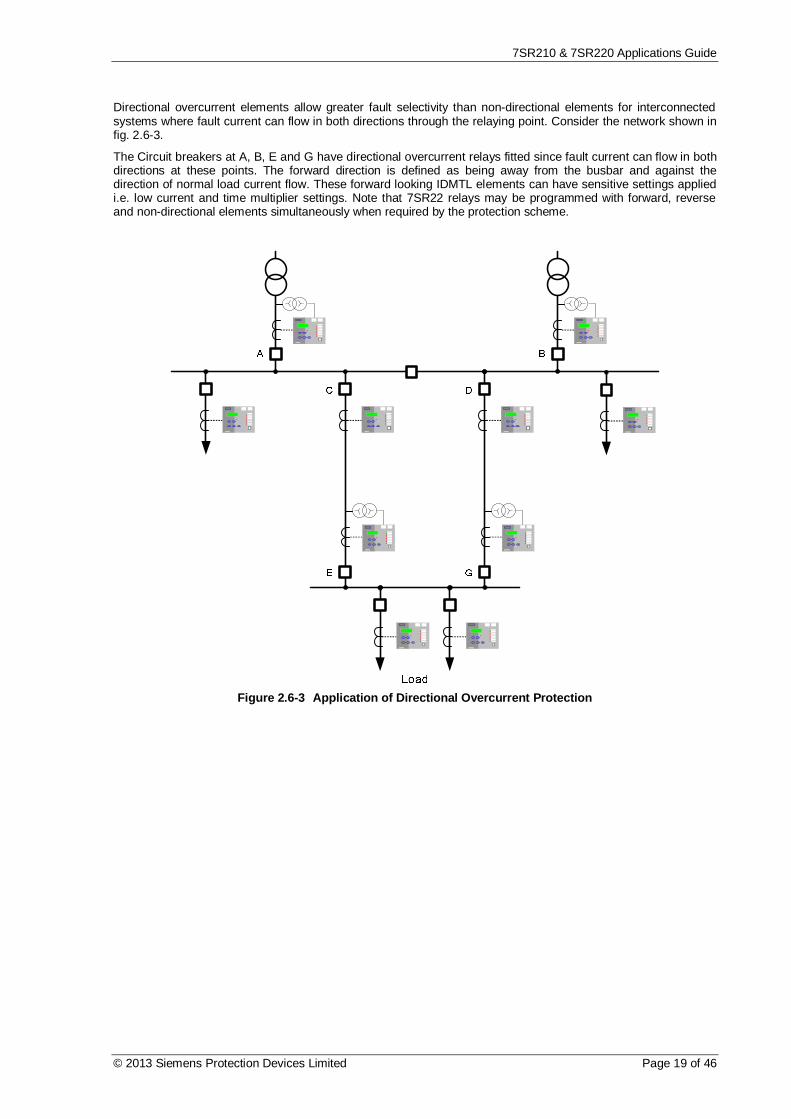
7SR210 & 7SR220 Applications Guide
© 2013 Siemens Protection Devices Limited Page 19 of 46
Directional overcurrent elements allow greater fault selectivity than non-directional elements for interconnectedsystems where fault current can flow in both directions through the relaying point. Consider the network shown infig. 2.6-3.
The Circuit breakers at A, B, E and G have directional overcurrent relays fitted since fault current can flow in bothdirections at these points. The forward direction is defined as being away from the busbar and against thedirection of normal load current flow. These forward looking IDMTL elements can have sensitive settings appliedi.e. low current and time multiplier settings. Note that 7SR22 relays may be programmed with forward, reverseand non-directional elements simultaneously when required by the protection scheme.
Figure 2.6-3 Application of Directional Overcurrent Protection

7SR210 & 7SR220 Applications Guide
Page 20 of 46 ©2015 Siemens Protection Devices Limited
Figure 2.6-4 Feeder Fault on Interconnected Network
Considering the D-G feeder fault shown in fig. 2.6-4: the current magnitude through breakers C and D will besimilar and their associated relays will similar prospective operate times. To ensure that only the faulted feeder isisolated G FWD must be set to be faster than C. Relay G will thus Trip first on FWD settings, leaving D to operateto clear the fault. The un-faulted Feeder C-E maintains power to the load.
Relays on circuits C and D at the main substation need not be directional to provide the above protection scheme.However additional directional elements could be mapped to facilitate a blocked overcurrent scheme of busbarprotection.
At A and B, forward looking directional elements enable sensitive settings to be applied to detect transformerfaults whilst reverse elements can be used to provide back-up protection for the relays at C and D.
By using different settings for forward and reverse directions, closed ring circuits can be set to grade correctlywhether fault current flows in a clockwise or counter clockwise direction i.e. it may be practical to use only onerelay to provide dual directional protection.
2 Out of 3 Logic
Sensitive settings can be used with directional overcurrent relays since they are directionalised in a way whichopposes the flow of normal load current i.e. on the substation incomers as shown on fig. 2.6-4. However onoccurrence of transformer HV or feeder incomer phase-phase faults an unbalanced load current may still flow asan un balanced driving voltage is present. This unbalanced load current during a fault may be significant wheresensitive overcurrent settings are applied - the load current in one phase may be in the operate direction andabove the relay setting.
Where this current distribution may occur then the relay is set to CURRENT PROTECTION>PHASEOVERCURRENT> 67 2-out-of-3 Logic = ENABLED
Enabling 2-out-of-3 logic will prevent operation of the directional phase fault protection for a single phase to earthfault. Dedicated earth-fault protection should therefore be used if required.

7SR210 & 7SR220 Applications Guide
© 2013 Siemens Protection Devices Limited Page 21 of 46
2.7 Directional Earth-Fault (50/51G, 50/51N, 51/51SEF)The directional earth-fault elements, either measure directly or derive from the three line currents the zerosequence current (operate quantity) and compare this against the derived zero phase sequence voltage(polarising quantity). The Technical Manual ‘Description of Operation’ details the method of measurement. Therequired setting is entered directly as dictated by the system impedances.
Example: -
Expected fault angle is -45° (i.e. residual current lagging residual voltage) therefore 67G Char Angle = -45°
However directional earth elements can be selectable to use either ZPS or NPS Polarising. This is to allow for thesituation where ZPS voltage is not available; perhaps because a 3-limb VT is being used. Care must be taken asthe Characteristic Angle will change if NPS Polarising is used.
Once again the fault angle is completely predictable, though this is a little more complicated as the method ofearthing must be considered.
Figure 2.7-1 Earth Fault Angles

7SR210 & 7SR220 Applications Guide
Page 22 of 46 ©2015 Siemens Protection Devices Limited
2.8 High Impedance Restricted Earth Fault Protection (64H)Restricted Earth Fault (REF) protection is applied to Transformers to detect low level earth faults in thetransformer windings. Current transformers are located on all connections to the transformer. During normaloperation or external fault conditions no current will flow in the relay element. When an internal earth fault occurs,the currents in the CTs will not balance and the resulting unbalance flows through the relay.
The current transformers may saturate when carrying high levels of fault current. The high impedance name isderived from the fact that a resistor is added to the relay leg to prevent relay operation due to CT saturation underthrough fault conditions.
The REF Trip output is configured to provide an instantaneous trip output from the relay to minimise damage fromdeveloping winding faults.
The application of the element to a Argus RM-Star transformer is shown in Figure 2.8-1. Although the connectionon the Argus RM winding is more correctly termed a Balanced Earth-Fault element, it is still usually referred to asRestricted Earth Fault because of the presence of the transformer.
Figure 2.8-1 Balanced and Restricted Earth-fault protection of Transformers
The calculation of the value of the Stability Resistor is based on the worst case where one CT fully saturates andthe other balancing CT does not saturate at all. A separate Siemens Protection Devices Limited Publication isavailable covering the calculation procedure for REF protection. To summarise this: -
The relay Stability (operating) Vs voltage is calculated using worst case lead burden to avoid relay operation forthrough-fault conditions where one of the CTs may be fully saturated. The required fault setting (primary operatecurrent) of the protection is chosen; typically, this is between 10 % and 25 % of the protected winding ratedcurrent. The relay setting current is calculated based on the secondary value of the operate current, note,however, that the summated CT magnetising current @ Vs must be subtracted to obtain the required relayoperate current setting.
Since the relay operate current setting and stability/operating voltage are now known, a value for the seriesresistance can now be calculated.
A check is made as to whether a Non-Linear Resistor is required to limit scheme voltage during internal faultconditions – typically where the calculated voltage is in excess of 2 kV.
The required thermal ratings for external circuit components are calculated.
BalancedEarth Fault
RestrictedEarth Fault

7SR210 & 7SR220 Applications Guide
© 2013 Siemens Protection Devices Limited Page 23 of 46
Composite overcurrent and REF protection can be provided using a multi-element relay as.
Figure 2.8-2 Composite Overcurrent and Restricted Earth-fault Protection
Although core-balance CTs are traditionally used with elements requiring sensitive pickup settings, cost and sizeusually precludes this on REF schemes. Instead single-Phase CTs are used and their secondary’s connected inparallel.
Where sensitive settings are required, the setting must be above any line charging current levels that can bedetected by the relay.
On occurrence of an out of zone earth fault the elevation of sound phase voltage to earth in a non-effectivelyearthed system can result in a zero sequence current of up 3 times phase charging current flowing through therelay location.
The step change from balanced 3-phase charging currents to this level of zero sequence current includestransients. It is recommended to allow for a transient factor of 2 to 3 when determining the limit of chargingcurrent. Based on the above considerations the minimum setting of a relay in a resistance earthed power systemis 6 to 9 times the charging current per phase.
High impedance differential protection is suitable for application to auto transformers as line currents are in phaseand the secondary current through the relay is balanced to zero by the use of CTs ratios at all three terminals.High impedance protection of this type is very sensitive and fast operating for internal faults.
25
non-linear resistor
seriesstabilising
resistor
overcurrentelements
REFelement
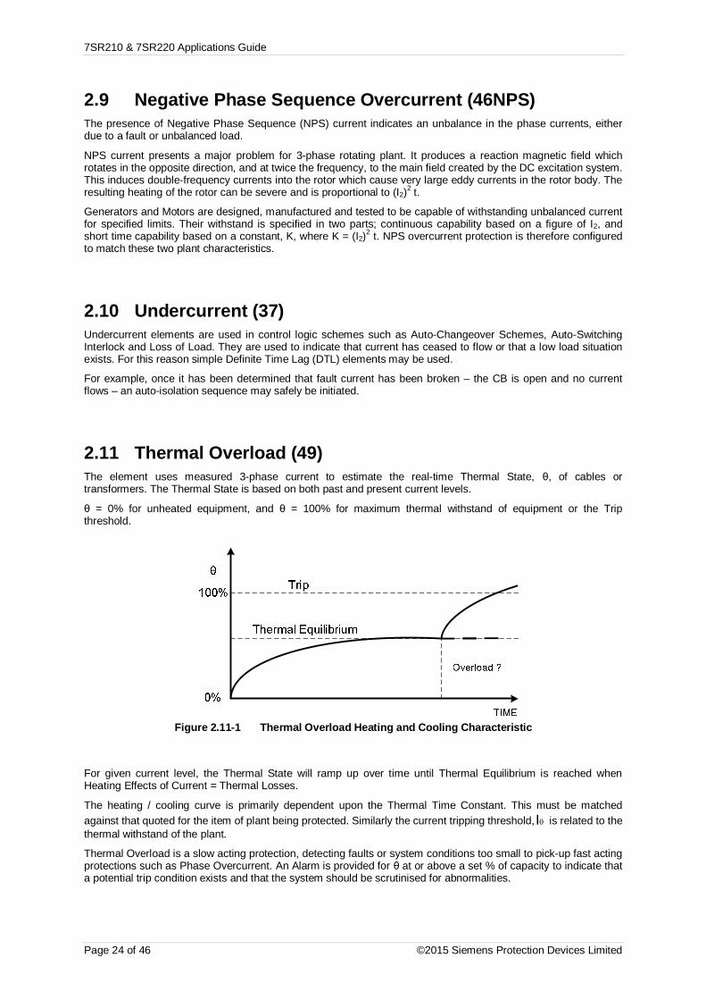
7SR210 & 7SR220 Applications Guide
Page 24 of 46 ©2015 Siemens Protection Devices Limited
2.9 Negative Phase Sequence Overcurrent (46NPS)The presence of Negative Phase Sequence (NPS) current indicates an unbalance in the phase currents, eitherdue to a fault or unbalanced load.
NPS current presents a major problem for 3-phase rotating plant. It produces a reaction magnetic field whichrotates in the opposite direction, and at twice the frequency, to the main field created by the DC excitation system.This induces double-frequency currents into the rotor which cause very large eddy currents in the rotor body. Theresulting heating of the rotor can be severe and is proportional to (I2)2 t.
Generators and Motors are designed, manufactured and tested to be capable of withstanding unbalanced currentfor specified limits. Their withstand is specified in two parts; continuous capability based on a figure of I2, andshort time capability based on a constant, K, where K = (I2)2 t. NPS overcurrent protection is therefore configuredto match these two plant characteristics.
2.10 Undercurrent (37)Undercurrent elements are used in control logic schemes such as Auto-Changeover Schemes, Auto-SwitchingInterlock and Loss of Load. They are used to indicate that current has ceased to flow or that a low load situationexists. For this reason simple Definite Time Lag (DTL) elements may be used.
For example, once it has been determined that fault current has been broken – the CB is open and no currentflows – an auto-isolation sequence may safely be initiated.
2.11 Thermal Overload (49)The element uses measured 3-phase current to estimate the real-time Thermal State, θ, of cables ortransformers. The Thermal State is based on both past and present current levels.
θ = 0% for unheated equipment, and θ = 100% for maximum thermal withstand of equipment or the Tripthreshold.
Figure 2.11-1 Thermal Overload Heating and Cooling Characteristic
For given current level, the Thermal State will ramp up over time until Thermal Equilibrium is reached whenHeating Effects of Current = Thermal Losses.
The heating / cooling curve is primarily dependent upon the Thermal Time Constant. This must be matchedagainst that quoted for the item of plant being protected. Similarly the current tripping threshold, qI is related to thethermal withstand of the plant.
Thermal Overload is a slow acting protection, detecting faults or system conditions too small to pick-up fast actingprotections such as Phase Overcurrent. An Alarm is provided for θ at or above a set % of capacity to indicate thata potential trip condition exists and that the system should be scrutinised for abnormalities.

7SR210 & 7SR220 Applications Guide
© 2013 Siemens Protection Devices Limited Page 25 of 46
2.12 Under/Over Voltage Protection (27/59)
Power system under-voltages on may occur due to:
System faults.
An increase in system loading,
Non-energized power system e.g. loss of an incoming transformer
During normal system operating conditions regulating equipment such as transformer On Load Tap Changers(OLTC) and generator Automatic Voltage Regulators (AVR) ensure that the system runs within acceptablevoltage limits.
7SR24 undervoltage/DTL elements can be used to detect abnormal undervoltage conditions due to systemoverloads. Binary outputs can be used to trip non-essential loads - returning the system back to its normaloperating levels. This ‘load shedding’ should be initiated via time delay elements so avoiding operation duringtransient disturbances. An under voltage scheme (or a combined under frequency/under voltage scheme) canprovide faster tripping of non-essential loads than under-frequency load shedding so minimising the possibility ofsystem instability.
Where a transformer is supplying 3-phase motors a significant voltage drop e.g. to below 80% may cause themotors to stall. An undervoltage element can be set to trip motor circuits when the voltage falls below a presetvalue so that on restoration of supply an overload is not caused by the simultaneous starting of all the motors. Atime delay is required to ensure voltage dips due to remote system faults do not result in an unnecessarydisconnection of motors.
To confirm presence/loss of supply, the voltage elements should be set to values safely above/below that where anormal system voltage excursion can be expected. The switchgear/plant design should be considered. The ‘Dead’level may be very near to the ‘live’ level or may be significantly below it. The variable hysteresis setting allows therelay to be used with all types of switchgear.
System over-voltages can damage component insulation. Excessive voltage may occur for: -
Sudden loss of load
A tap changer run-away condition occurs in the high voltage direction,
Generator AVR equipment malfunctions or
Reactive compensation control malfunctions.
System regulating equipment such as transformer tap changers and generator AVRs may correct the overvoltage– unless this equipment mal-functions. The overvoltage/DTL elements can be used to protect against damagecaused by system overvoltages.
If the overvoltage condition is small a relatively long DTL time delay can be used. If the overvoltage is moresevere then another element, set at a higher pickup level and with a shorter DTL can be used to isolate the circuitmore quickly. Alternatively, elements can be set to provide alarm and tripping stages, with the alarm levels setlower than the tripping stages.
The use of DTL settings allows a grading system to be applied to co-ordinate the network design, the regulatingplant design, system plant insulation withstand and with other overvoltage relays elsewhere on the system. TheDTL also prevents operation during transient disturbances.
The use of IDMTL protection is not recommended because of the difficulty of choosing settings to ensure correctco-ordination and security of supply.

7SR210 & 7SR220 Applications Guide
Page 26 of 46 ©2015 Siemens Protection Devices Limited
2.13 Neutral Overvoltage (59N)Neutral Overvoltage Displacement (Residual Overvoltage) protection is used to detect an earth fault where little orno earth current flows.
This can occur where a feeder has been tripped at its HV side for an earth fault, but the circuit is still energisedfrom the LV side via an unearthed transformer winding. Insufficient earth current would be present to cause a trip,but residual voltage would increase significantly; reaching up to 3-times the normal phase-earth voltage level.
If Neutral Overvoltage protection is used, it must be suitably time graded with other protections in order to preventunwanted tripping for external system earth faults.
Figure 2.13-1 NVD Application
Typically NVD protection measures the residual voltage (3V0) directly from an open delta VT or from capacitorcones – see fig. 2.13-2 below.
Figure 2.13-2 NVD Protection Connections

7SR210 & 7SR220 Applications Guide
© 2013 Siemens Protection Devices Limited Page 27 of 46
2.13.1 Application with Capacitor Cone UnitsCapacitor cones provide a cost effective method of deriving residual voltage. The wide range of capacitor conecomponent values used by different manufacturer’s means that the relay cannot be connected directly to thecones.
The external adaptor unit contains parallel switched capacitors that enable a wide range of values to be selectedusing a DIL switch and hence the Capacitor Cone output can be scaled to the standard relay input range.
2.13.2 Derived NVD VoltageAlternatively NVD voltage can be derived from the three phase to neutral voltages, this setting is available withinthe relay. Note with this method the NVD protection may mal-operate during a VT Fail condition.
2.14 Negative Phase Sequence Overvoltage (47)Negative Phase Sequence (NPS) protection detects phase unbalances and is widely used in protecting rotatingplant such as motors and generators. However such protection is almost universally based on detecting NPSCurrent rather than Voltage. This is because the NPS impedance of motors etc. is much less than the PositivePhase Sequence (PPS) impedance and therefore the ratio of NPS to PPS Current is much higher than theequivalent ratio of NPS to PPS Voltage.
NPS Voltage is instead used for monitoring busbar supply quality rather than detecting system faults. Thepresence of NPS Voltage is due to unbalanced load on a system. Any system voltage abnormality is importantsince it will affect every motor connected to the source of supply and can result in mass failures in an industrialplant.
The two NPS Voltage DTL elements should therefore be used as Alarms to indicate that the level of NPS hasreached abnormal levels. Remedial action can then be taken, such as introducing a Balancer network ofcapacitors and inductors. Very high levels of NPS Voltage indicate incorrect phase sequence due to an incorrectconnection.

7SR210 & 7SR220 Applications Guide
Page 28 of 46 ©2015 Siemens Protection Devices Limited
2.15 Under/Over Frequency (81)During normal system operation the frequency will continuously vary over a relatively small range due to thechanging generation/load balance. Excessive frequency variation may occur for: -
Loss of generating capacity, or loss of mains supply (underfrequency): If the governors and otherregulating equipment cannot respond to correct the balance, a sustained underfrequency condition maylead to a system collapse.
Loss of load – excess generation (overfrequency): The generator speeds will increase causing aproportional frequency rise. This may be unacceptable to industrial loads, for example, where therunning speeds of synchronous motors will be affected.
In the situation where the system frequency is falling rapidly it is common practise to disconnect non-essentialloads until the generation-load balance can be restored. Usually, automatic load shedding, based onunderfrequency is implemented. Underfrequency relays are usually installed on the transformer incomers ofdistribution or industrial substations as this provides a convenient position from which to monitor the busbarfrequency. Loads are disconnected from the busbar (shed) in stages until the frequency stabilises and returns toan acceptable level.
The relay has six under/over frequency elements.
An example scheme may have the first load shedding stage set just below the nominal frequency, e.g. between49.0 Hz and 49.5 Hz. A time delay element would be associated with this to allow for transient dips in frequencyand to provide a time for the system regulating equipment to respond. If the first load shedding stage disconnectssufficient plant the frequency will stabilise and perhaps return to nominal. If, however, this is not sufficient then asecond load shedding stage, set at a lower frequency, will shed further loads until the overload is relieved. Thisprocess will continue until all stages have operated. In the event of the load shedding being unsuccessful, a finalstage of underfrequency protection should be provided to totally isolate all loads before plant is damaged, e.g.due to overfluxing.
An alternative type of load shedding scheme would be to set all underfrequency stages to about the samefrequency setting but to have different length time delays set on each stage. If after the first stage is shed thefrequency doesn’t recover then subsequent stages will shed after longer time delays have elapsed.
Generator
NetworkIncomer
G59
300/5
STAGE 1: Least importantSTAGE 2STAGE 3STAGE 4
EssentialLoad
STAGE 5STAGE 6
61 25 5 3 4 2 4
Figure 2.15-1 Load Shedding Scheme Using Under-Frequency Elements

7SR210 & 7SR220 Applications Guide
© 2013 Siemens Protection Devices Limited Page 29 of 46
Section 3: CT Requirements
3.1 CT Requirements for Overcurrent and Earth FaultProtection
3.1.1 Overcurrent Protection CTsa) For industrial systems with relatively low fault current and no onerous grading requirements - a class
10P10 with VA rating to match the load.
b) For utility distribution networks with relatively high fault current and several grading stages - a class5P20, with VA rating to match the load.
Note: If an accuracy limit factor is chosen which is much lower than the maximum fault current it will benecessary to consider any effect on the protection system performance and accuracy e.g. grading margins.
For i.d.m.t.l. applications, because the operating time at high fault current is a definite minimum value, partialsaturation of the CT at values beyond the overcurrent factor has only a minimal effect. However, this must betaken into account in establishing the appropriate setting to ensure proper grading.
c) For dtl applications utilities as for (b) above - a class 5P10 (or 20), with rated burden to suit the load.
Note: Overcurrent factors do not need to be high for definite time protection because once the setting isexceeded magnitude accuracy is not important. Often, however, there is also the need to considerinstantaneous HighSet overcurrent protection as part of the same protection system and the settings wouldnormally be of the order of 10x the CT rating or higher. Where higher settings are to be used then theovercurrent factor must be raised accordingly, e.g. to P20.
3.1.2 Earth Fault Protection CTsConsiderations and requirements for earth fault protection are the same as for Phase fault. Usually the relayemploys the same CT's e.g. three phase CTs star connected to derive the residual earth fault current.
The accuracy class and overcurrent accuracy limit factors are therefore already determined and for both thesefactors the earth fault protection requirements are normally less onerous than for overcurrent.
3.2 CT Requirements for High Impedance Restricted EarthFault Protection
For high impedance REF it is recommended that: -
Low reactance CTs to IEC 60044 Class PX are used, this allows a sensitive current setting to be applied.
All CT’s should, if possible have identical turns ratios.
The knee point voltage of the CTs must be greater than 2 x 64H setting voltage Vs.
Where the REF function is used then this dictates that the other protection functions are also used with class PXCTs.
A full explanation of how to specify CTs for use with REF protection, and set REF relays is available on ourwebsite: www.siemens.com/energy

7SR210 & 7SR220 Applications Guide
Page 30 of 46 ©2015 Siemens Protection Devices Limited
Section 4: Control Functions
4.1 Auto-reclose ApplicationsAutomatic circuit reclosing is extensively applied to overhead line circuits where a high percentage of faults thatoccur are of a transient nature. By automatically reclosing the circuit-breaker the function attempts to minimise theloss of supply to the customer and reduce the need for manual intervention.
The function supports up to 4 ARC sequences. That is, 4 x Trip / Recloses followed by a Trip & Lockout. A lockoutcondition prevents any further attempts, automatic or manual, to close the circuit-breaker. The number ofsequences selected depends upon the type of faults expected. If there are a sufficient percentage of semi-permanent faults which could be burnt away, e.g. fallen branches, a multi shot scheme would be appropriate.Alternatively, if there is a high likelihood of permanent faults, a single shot scheme would minimise the chances ofcausing damage by reclosing onto a fault. In general, 80% of faults will be cleared by a single Trip and Reclosesequence. A further 10% will be cleared by a second Trip and Reclose. Different sequences can be selected fordifferent fault types (Phase/Earth/Sensitive Earth faults).
The Deadtime is the interval between the trip and the CB close pulse being issued. This is to allow for the line togo ‘dead’ after the fault is cleared. The delay chosen is a compromise between the need to return the line toservice as soon as possible and prevented unnecessary trips through re-closing too soon. The Reclaim Time isthe delay following a re-closure before the line can be considered back in service. This should be set long enoughto allow for protection operation for the same fault, but not so long that two separate faults could occur in thesame Autoreclose (ARC) sequence and cause unnecessary lockouts.
The Sequence Fail Timer provides an overall maximum time limit on the ARC operation. It should therefore belonger than all the set delays in a complete cycle of ARC sequences; trip delays, Deadtimes, Reclaim Time etc.Generally this will only be exceeded if the circuit-breaker has either failed to open or close.
Since large fault currents could potentially damage the system during a prolonged ARC sequence, there are alsosettings to identify which protection elements are High-sets and these can cause an early termination of thesequence.
Where a relay is to operate as part of an ARC scheme involving a number of other relays, the feature attempts toclear any faults quickly without regard to normal fault current grading. It does this by setting each Trip element tobe either Delayed or Instantaneous. Instantaneous Trips are set to operate at just above maximum load currentwith small delays while Delayed Trips are set to suit actual fault levels and with delays suitable for currentgrading.
A typical sequence would be 2 Instantaneous Trips followed by a Delayed Trip & Lockout: -
• When any fault occurs, the relay will trip instantaneously and then reclose.
• If this does not clear the fault, the relay will do the same again.
• If this still does not clear the fault, the fault is presumed to be permanent and the next Trip will beDelayed and so suitable for grading with the rest of the network. Thus allowing downstreamprotection time to operate.
• This Trip will Lockout the ARC sequence and prevent further recloses.
It is important that all the relays in an ARC scheme shadow this process – advancing through their own ARCsequences when a fault is detected by an element pickup even though they are not actually causing a trip orreclose. This is termed Sequence Co-ordination and prevents an excessive number of recloses as eachsuccessive relay attempts to clear the fault in isolation. For this reason each relay in an ARC scheme must be setwith identical Instantaneous and Delayed sequence of trips.
Figure 4.1-1 Sequence Co-ordination

7SR210 & 7SR220 Applications Guide
© 2013 Siemens Protection Devices Limited Page 31 of 46
The relay closest to the fault (D) would step through its Instantaneous Trips in an attempt to clear the fault. Ifunsuccessful, the relay would move to a Delayed Trip sequence.
The other relays in the network (A, B and C) would recognise the sequence of Pick-up followed by current switch-off as ARC sequences. They would therefore also step to their Delayed Trip to retain co-ordination with therespective downstream devices.
The next Trip would be subject to current grading and Lockout the ARC sequence such that the fault is cleared bythe correct CB.
4.1.1 Auto-Reclose Example 1Requirement: Settings shall provide four phase fault recloses – two instantaneous and two delayed - and only tworecloses for faults detected by the SEF protection.
Proposed settings include:
CONTROL & LOGIC > AUTORECLOSE PROT’N:
79 P/F Inst Trips: 50-1
79 P/F Delayed Trips: 51-1
79 SEF Delayed Trips: 51SEF-1
CONTROL & LOGIC > AUTORECLOSE CONFIG
79 Num Shots: 4
CONTROL & LOGIC > AUTORECLOSE CONFIG > P/F SHOTS
79 P/F Prot’n Trip 1 : Inst
79 P/F Prot’n Trip 2 : Inst
79 P/F Prot’n Trip 3 : Delayed
79 P/F Prot’n Trip 4 : Delayed
79 P/F Delayed Trips to Lockout : 3
CONTROL & LOGIC > AUTORECLOSE CONFIG > SEF SHOTS
79 SEF Prot’n Trip 1 : Delayed
79 SEF Prot’n Trip 2 : Delayed
79 SEF Delayed Trips to Lockout : 3
Note that Instantaneous’ shots are inhibited if the shot is defined as ‘Delayed’

7SR210 & 7SR220 Applications Guide
Page 32 of 46 ©2015 Siemens Protection Devices Limited
4.1.2 Auto-Reclose Example 2 (Use of Quicklogic with AR)
TIM
E
Figure 4.1-2 Example of Logic Application
Requirement: The relay at location ‘A’ it is required to provide a reclose sequence of 2 Instantaneous followed by2 delayed recloses. Where the fault current level is between the values ‘I1’ and ‘I2’ and the first trip is initiatedfrom the 51-1 (IDMT) element, the IDMT characteristic should trip the CB and lockout the auto-reclose.
Typical settings are:
CONTROL & LOGIC > AUTORECLOSE PROT’N:
79 P/F Inst Trips: 50-1
79 P/F Delayed Trips: 51-1
CONTROL & LOGIC > AUTORECLOSE CONFIG > P/F SHOTS
79 P/F Prot’n Trip 1 : Inst
79 P/F Prot’n Trip 2 : Inst
79 P/F Prot’n Trip 3 : Delayed
79 P/F Prot’n Trip 4 : Delayed
The above settings are suitable at values of fault current above ‘I2’ however were a fault to occur with a currentvalue between ‘I1’ and ‘I2’ this would be detected by the 51-1 element only. As Prot’n Trip 1 = Inst then the relaywould trip and reclose whereas it is required to lockout for this occurrence.
To provide a lockout for the above faults an additional element 50-2 with identical settings to 50-1 is assigned asa Delayed Trip and is used in conjunction with the Quick Logic feature i.e.
OUTPUT CONFIG>OUTPUT MATRIX: 51-1 = V1
OUTPUT CONFIG>OUTPUT MATRIX: 50-2 = V2
OUTPUT CONFIG>OUTPUT MATRIX: E1 = V3
CONTROL & LOGIC>QUICK LOGIC: E1 = V1.!V2
INPUT CONFIG>INPUT MATRIX: 79 Lockout = V3

7SR210 & 7SR220 Applications Guide
© 2013 Siemens Protection Devices Limited Page 33 of 46
4.2 Quick Logic Applications
4.2.1 Auto-Changeover Scheme Example
Figure 4.2-1 Example Use of Quick Logic
The MV installation illustrated above is fed from two incomers. To limit the substation fault level the busbar is runwith CB3 open. When a fault occurs on one of the incomers it is isolated by the circuit protection. To re-supply thedisconnected loads from the remaining incomer CB3 is closed.
If the line fault occurs on incomer 1 it must be confirmed that CB 1 has opened before CB3 can be closed. Therelay on incomer 1 confirms that a trip has been issued to CB1 (e.g. Binary Output 2), that CB 1 has opened (e.g.Binary Input 1) and that no current flows in the circuit (e.g. 37-1 = Virtual 1): -
Incomer 1 Relay is Configured:
CB1 Open auxiliary switch wired to B.I. 1
Trip output to CB1 = B.O. 2
OUTPUT CONFIG>OUTPUT MATRIX: 37-1 = V1
OUTPUT CONFIG>OUTPUT MATRIX: E1 = BO3
CONTROL & LOGIC>QUICK LOGIC: E1 = O2.I1.V1
The output from Incomer 1 (BO3) relay is input to the relay on CB 3 (Binary Input 1). A panel switch may be usedto enable the On-Load Change-over scheme (Binary Input 2). Before Closing CB3 a check may be made thatthere is no voltage on busbar 1 (27/59-1 = Virtual 1). CB 3 is closed from Binary Output 3.
CB3 Relay is Configured:
Panel switch (ON-Load Change-over Enabled) wired to B.I. 1
OUTPUT CONFIG>OUTPUT MATRIX: 27/59-1 = V1
OUTPUT CONFIG>OUTPUT MATRIX: E1 = BO3
CONTROL & LOGIC>QUICK LOGIC: E1 = I1.I2.V1
If required a time delay can be added to the output using the CONTROL & LOGIC > QUICK LOGIC: E1Pickup Delay setting.

7SR210 & 7SR220 Applications Guide
Page 34 of 46 ©2015 Siemens Protection Devices Limited
Section 5: Supervision Functions
5.1 Circuit-Breaker Fail (50BF)Where a circuit breaker fails to operate to clear fault current the power system will remain in a hazardous stateuntil the fault is cleared by remote or back-up protections. To minimise any delay, CB Failure protection providesa signal to either re-trip the local CB or back-trip ‘adjacent’ CBs.
The function is initiated by the operation of user selectable protection functions or from a binary input. Currentflow is monitored after a tripping signal has been issued if any of the 50BF current check elements have not resetbefore the timers have expired an output is given. For CB trips where the fault is not current related an additionalinput is provided (50BF Mech Trip) which monitors the CB closed input and provides an output if the circuitbreaker has not opened before the timers expire.
The relay incorporates a two-stage circuit breaker fail feature. For some systems, only the first will be used andthe CB Failure output will be used to back-trip the adjacent CB(s). On other systems, however, this output will beused to re-trip the local CB to minimise potential disruption to the system; if possible via a secondary trip coil andwiring. The second CB Failure stage will then be used to back-trip the adjacent CB(s).
If the CB is faulty and unable to open, a faulty contact can be wired to the CB faulty input of the relay and if a tripoccurs while this input is raised the CB fail delay timers may be by-passed to allow back tripping to occur withoutdelay.
Figure 5.1-1 Circuit Breaker Fail
5.1.1 Settings Guidelines50BF Setting
The phase current setting must be set below the minimum protection setting current.
50BF Setting-I4
The EF or SEF current setting must be set below the minimum protection setting current.
50BF Ext Trig
Any binary input can be mapped to this input to trigger the circuit breaker fail function. Note current must beabove setting for the function to operate.
50BF Mech Trip
Any binary input can be mapped to this input to trigger the circuit breaker fail function. Note for the function tooperate the circuit breaker closed input is used to detect a failure, not the current.
50BF CB Faulty
Any binary input can be mapped to this input, if it is energised when a trip initiation is received an output will begiven immediately (the timers are by passed).

7SR210 & 7SR220 Applications Guide
© 2013 Siemens Protection Devices Limited Page 35 of 46
50BF DTL1/50BF DTL2
The time delays run concurrently within the relay. The time delay applied to the CB Fail protection must be inexcess of the longest CB operate time + relay reset time + a safety margin.
First Stage (Retrip)
Trip Relay operate time 10 ms
Reset Time 20 ms
CB Tripping time 50 ms
Safety Margin 40 ms
Overall First Stage CBF Time Delay 120 ms
Second Stage (Back Trip)
First CBF Time Delay 120 ms
Trip Relay operate time 10 ms
CB Tripping time 50 ms
Reset Time of measuring element 20 ms
Margin 60 ms
Overall Second Stage CBF Time Delay 260 ms
The safety margin is extended by 1 cycle for the second CBF stage as this will usually involve a back-trip of aBusbar tripping scheme.
The timing sequence for each stage of the circuit breaker fail function is as below.
CB BacktripSucessful
20 40 60 80 100 120 140 160 180 200 220 240 260 280 300 320 340
SystemFault
ms from faultoccuring
RelayOperationand CBF
TimerStarted
MainTrip
RelayOperation
Failure ofCB to trip
Reset ofCBF elementsdoes not occur
BacktripOperation
BacktripTrip Relay
CB Operate Time
Stage 1 CBF Timer (Backtrip) = 120ms
Figure 5.1-2 Single Stage Circuit Breaker Fail Timing
Stage 1 CBF Timer (Retrip) = 120ms
Failed CB RetripOperation
40 60 80 100 120 140 160 180 200 220 240 260 280 300 320 360340
SystemFault
RelayOperationand CBF
TimerStarted
MainTrip
RelayOperation
CB'sFails to
Trip
No Reset ofCBF elements
CBF RetripOperation
CBF RetripTrip Relay
CB Operate Time
Stage 2 CBF Timer (Backtrip) = 250ms
No Reset ofCBF elements
CBF Back tripOperation
BacktripTrip RelayOperation
Operation of allBB CB's
Reset ofCBF elements
ms from faultoccuring
Figure 5.1-3 Two Stage Circuit Breaker Fail Timing

7SR210 & 7SR220 Applications Guide
Page 36 of 46 ©2015 Siemens Protection Devices Limited
5.2 Current Transformer Supervision (60CTS)When a CT fails, the current levels seen by the protection become unbalanced. A large level of NPS current istherefore detected - around 0.3 x In for one or two CT failures. However this condition would also occur for asystem fault. To differentiate between the two conditions, the element uses NPS voltage to restrain the CTSalgorithm as show in the accompanying table.
NPS Current NPS Voltage Decision
> Setting > Setting System Fault
> Setting < Setting CT Failure
Table 5-2 Determination of CT Failure (1 or 2 Phases)
Following a CT Failure, there should be little or no NPS voltage. Perhaps 0.1 x Vn as a maximum.
Operation is subject to a time delay to prevent operation for transitory effects.
A 3-phase CT failure is considered so unlikely (these being independent units) that this condition is not tested for.

7SR210 & 7SR220 Applications Guide
© 2013 Siemens Protection Devices Limited Page 37 of 46
5.3 Voltage Transformer Supervision (60VTS)Although VTs rarely fail themselves, VT Supervision presents a common application because of the failure ofprotective Fuses connected in series with the VTs.
When a VT failure occurs on one or two phases, the voltage levels seen by the protection become unbalanced. Alarge level of NPS voltage is therefore detected - around 0.3 x Vn for one or two VT failures. However thiscondition would also occur for a system fault. To differentiate between the two conditions, the element uses NPScurrent to restrain the VTS algorithm as show in the accompanying table.
NPS Voltage NPS Current Decision
> Setting > Setting System Fault
> Setting < Setting VT Failure
Table 5-3 Determination of VT Failure (1 or 2 Phases)
Following a VT Failure, the level of NPS current would be dependent solely upon load imbalance - perhaps 0.1 xIn as a maximum.
Operation is subject to a time delay to prevent operation for transitory effects.
NPS voltage and current quantities are used rather than ZPS since the latter makes it difficult to differentiatebetween a VT failure and a Phase-Phase fault. Both conditions would generate little or no ZPS current. Howeverthe element provides an option to use ZPS quantities to meet some older specifications.
There are possible problems with using NPS quantities due to load imbalances. These would also generatesignificant levels of NPS current and so possibly cause a VT failure to be missed. This problem can be overcomeby careful selection of settings, however, setting the NPS current threshold above the level expected forimbalance conditions.
If a failure occurs in all 3 Phases of a Voltage Transformer, then there will be no NPS or ZPS voltage to work with.However the PPS Voltage will fall below expected minimum measurement levels.
This could also be due to a ‘close in’ fault and so PPS Current must remain above minimum load level BUT belowminimum fault level.
PPS Voltage PPS Current Decision
< Setting > Minimum Fault Level System Fault
< Setting Minimum Load Level <
AND
< Minimum Fault Level
VT Failure
Table 5-4 Determination of VT Failure (3 Phases)
Operation is again subject to a time delay to prevent operation for transitory effects.
Alternatively a 3 Phase VT failure can be signalled to the relay via a Binary Input taken from the Trip output of anexternal MCB. This can also be reset by a Binary Input signal.
VTS would not normally be used for tripping - it is an alarm rather than fault condition. However the loss of a VTwould cause problems for protection elements that have voltage dependant functionality. For this reason, therelay allows these protection elements - under-voltage, directional over-current, etc. - to be inhibited if a VT failureoccurs.
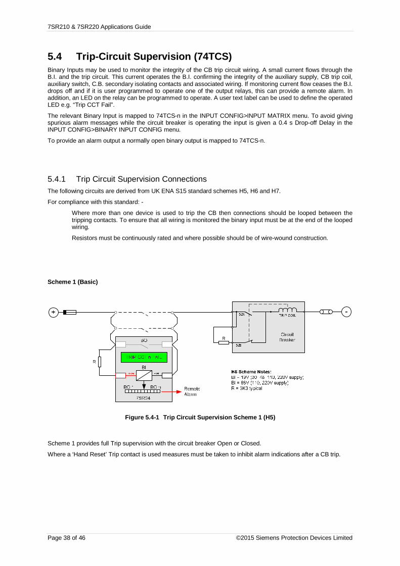
7SR210 & 7SR220 Applications Guide
Page 38 of 46 ©2015 Siemens Protection Devices Limited
5.4 Trip-Circuit Supervision (74TCS)Binary Inputs may be used to monitor the integrity of the CB trip circuit wiring. A small current flows through theB.I. and the trip circuit. This current operates the B.I. confirming the integrity of the auxiliary supply, CB trip coil,auxiliary switch, C.B. secondary isolating contacts and associated wiring. If monitoring current flow ceases the B.I.drops off and if it is user programmed to operate one of the output relays, this can provide a remote alarm. Inaddition, an LED on the relay can be programmed to operate. A user text label can be used to define the operatedLED e.g. “Trip CCT Fail”.
The relevant Binary Input is mapped to 74TCS-n in the INPUT CONFIG>INPUT MATRIX menu. To avoid givingspurious alarm messages while the circuit breaker is operating the input is given a 0.4 s Drop-off Delay in theINPUT CONFIG>BINARY INPUT CONFIG menu.
To provide an alarm output a normally open binary output is mapped to 74TCS-n.
5.4.1 Trip Circuit Supervision ConnectionsThe following circuits are derived from UK ENA S15 standard schemes H5, H6 and H7.
For compliance with this standard: -
Where more than one device is used to trip the CB then connections should be looped between thetripping contacts. To ensure that all wiring is monitored the binary input must be at the end of the loopedwiring.
Resistors must be continuously rated and where possible should be of wire-wound construction.
Scheme 1 (Basic)
Figure 5.4-1 Trip Circuit Supervision Scheme 1 (H5)
Scheme 1 provides full Trip supervision with the circuit breaker Open or Closed.
Where a ‘Hand Reset’ Trip contact is used measures must be taken to inhibit alarm indications after a CB trip.

7SR210 & 7SR220 Applications Guide
© 2013 Siemens Protection Devices Limited Page 39 of 46
Scheme 2 (Intermediate)
Figure 5.4-2 Trip Circuit Supervision Scheme 2 (H6)
Scheme 2 provides continuous Trip Circuit Supervision of trip coil with the circuit breaker Open or Closed. It doesnot provide pre-closing supervision of the connections and links between the tripping contacts and the circuitbreaker and may not therefore be suitable for some circuits which include an isolating link.
Scheme 3 (Comprehensive)
Figure 5.4-3 Trip Circuit Supervision Scheme 3 (H7)
Scheme 3 provides full Trip supervision with the circuit breaker Open or Closed.

7SR210 & 7SR220 Applications Guide
Page 40 of 46 ©2015 Siemens Protection Devices Limited
5.5 Inrush Detector (81HBL2)This element detects the presence of high levels of 2nd Harmonic current which is indicative of transformer Inrushcurrent at switch-on. These currents may be above the operate level of the overcurrent elements for a shortduration and it is important that the relay does not issue an incorrect trip command for this transient networkcondition.
If a magnetic inrush condition is detected operation of the overcurrent elements can be blocked.
Calculation of the magnetising inrush current level is complex. However a ratio of 20% 2nd Harmonic toFundamental current will meet most applications without compromising the integrity of the Overcurrent protection.
There are 3 methods of detection and blocking during the passage of magnetising inrush current.
Phase Blocking only occurs in those phases where Inrush is detected.
Large, Single Phase Transformers – Auto-transformers.
Cross All 3-phases are blocked if Inrush is detected in any phase.
Traditional application for most Transformers but can give delayed operation for Switch-on to Earth Fault conditions.
Sum Composite 2nd Harmonic content derived for all 3-phases and then compared toFundamental current for each individual phase.
Provides good compromise between Inrush stability and fast fault detection.
Table 5-5 Magnetic Inrush Bias
5.6 Broken Conductor / Load Imbalance (46BC)This feature is used to detect an open circuit condition when a conductor breaks or a mal-operation occurs inphase segregated switchgear.
There will be little or no fault current and so overcurrent elements will not detect the condition. However thecondition can be detected because there will be a high content of NPS (unbalance) current present.
An NPS / PPS ratio > 50% will result from a Broken Conductor condition.
Operation is subject to a time delay to prevent operation for transitory effects.
5.7 Circuit-Breaker MaintenanceThe Relay provides CB Total Trip Count, CB Delta Trip Count, CB Count to AR Block and CB Frequent OperationCounters along with an I2t CB Wear Counter to estimate the amount of wear and tear experienced by a Circuit-Breaker. Alarm can be provided once set levels have been exceeded.
Typically estimates obtained from previous circuit-breaker maintenance schedules or manufacturers data sheetsare used for setting these alarm levels. The relay instrumentation provides the current values of these counters.

7SR210 & 7SR220 Applications Guide
© 2013 Siemens Protection Devices Limited Page 41 of 46
5.8 Load Blinder (21)
NB: It is important to observe the convention regarding Forward and Reverse directions of current.
Load Blinders are used with directional overcurrent elements to block forward tripping during periods of high loadcurrents that can occur in distribution networks. The blinder is operated during user defined load conditions and isused in conjunction with the relay protection elements.
One of the major factors contributing to high load conditions is an increase of distributed generation capacitywhich can feed power back into the network contrary to the ‘normal’ direction of power flow. This can result incurrent levels above the relay setting and can cause tripping of overcurrent elements.
One typical example is on paralleled incoming transformer circuits, forward directional overcurrent elements areparametised such that they detect faults on the transformer LV connections for currents flowing in the directioncontrary to the ‘normal’ load flow. These forward elements have a relatively low current setting, typically <45% oftransformer rating, as current normally only flows in this direction during fault conditions. When embeddedgeneration is connected into the downstream network, these relays limit the level of current that can be fed backinto the grid.
Load Blinders measure the system impedance and are set to differentiate between a fault having a relatively lowimpedance and a fault having a relatively high impedance. Additional measurands are also considered to increasethe security of operation.
Figure 5.8-1 Paralleled Transformers and Feeders

7SR210 & 7SR220 Applications Guide
Page 42 of 46 ©2015 Siemens Protection Devices Limited
5.9 Load Blinder Design
5.9.1 Application view
It is important to observe the convention regarding Forward and Reverse directions of current.
Load Blinders are designed to block forward overcurrent elements from tripping during defined load conditions.
User settings 21LB-1/3P Impedance, 21LB-1/3P Angle +ve and 21LB-1/3P Angle -ve (‘a’, ‘b’ and ‘c’ in Figure5.9.1-1 Impedance Setting and Angle Setting) allow the user to define the Blinder region depending on thenetwork configuration - specifically the line loading and fault levels.
The measured impedance:
a. Is used to confirm the forward or reverse flow of current i.e. load blinder operated.b. Is used to confirm that current flow is outside the defined limits of load flow i.e. load blinder not operated.
The transition between operated and non-operated is subject to a 5 degree hysteresis adjustment.
+R
+X
PhaseFault
BlockZone
LoadImpedance
b
a
NominalImpedanceZ = 1p.u. =VL / (√3 x I)
c-R
-X
Vpps value Point 1Point 2
Point 3Point 4
0360
Trip LevelI = Vs / Z
OperateZone
a = 21LB-3P Impedancesettingb = 21LB-3P Angle +vesettingc = 21LB-3P Angle -vesetting
Point 6Point 5
BlockZone
LoadImpedance
ba
c
Point 7
Point 10Point 9
Point 8
Figure 5.9.1-1 Impedance Setting and Angle Setting

7SR210 & 7SR220 Applications Guide
© 2013 Siemens Protection Devices Limited Page 43 of 46
5.9.2 Design View5.9.2.1 Load Blinder 3Ph
Figure 5.9.2.1-1 Logic Diagram 3 Phase
The 3-phase load blinder has the following setting parameters:21LB – 3P Angle +ve21LB – 3P Angle -ve21LB – 3P Impedance21LB – 3P VPPS21LB – 3P INPS
The design of Load Blinder 3Ph takes into consideration that the protection blocking should only be issued duringdefinable allowable system power flow conditions i.e. an overcurrent blocking signal can only be issued when:
a. Positive Sequence Voltage Vpps is not significantly reduced i.e. is above the 21LB-3P VPPS Setting.AND
b. Negative Sequence Current Inps is lower than 21LB-3P INPS SettingAND
c. The impedance measured in all phases is within the operate zone.Zpps is calculated from Vpps and Ipps. The calculated Zpps is used to determine if the impedance is inthe operate zone i.e. greater than the 21LB-3P Impedance setting and less than the 21LB-3P Anglesettings. Suitable settings can be chosen to provide overcurrent blocking in the forward or reversedirections.

7SR210 & 7SR220 Applications Guide
Page 44 of 46 ©2015 Siemens Protection Devices Limited
5.9.2.2 Load Blinder 1PhThe single phase Load Blinder provides phase segregated blocking outputs. The Inps level is not consideredwhereas operation of the load blinder is inhibited during earth fault conditions i.e. when the Izps level exceeds theI21LB-1P IZPS setting.
Figure 5.9.2.2-1 Logic Diagram 1 Phase
The single phase load blinder has the following setting parameters:21LB – 1P Angle +ve21LB – 1P Angle -ve21LB – 1P Impedance21LB – 1P VPPS21LB – 1P IZPS
The design of single phase load blinder takes into consideration the following effects of a high unbalanced loadnon-fault condition. The blinder is operated when:
a. Positive Sequence Voltage Vpps is not significantly changed. A high 21LB-1P VPPS setting will allowinhibiting Load Blinders in case of larger voltage drops (representing fault situation).AND
b. Zero Sequence Current Izps is lower than 21LB-1P IZPS Setting.,AND
c. The impedance measured per phase is within the operate zone.Zphase is calculated from Vphase (peak) and Iphase (peak). The calculated Zphase is used todetermine if the impedance for that phase is in the operate zone i.e. greater than 21LB-1P Impedancesetting and less than 21LB-1P Angle settings.Suitable settings can be chosen to provide outputs in the forward or reverse directions.

7SR210 & 7SR220 Applications Guide
© 2013 Siemens Protection Devices Limited Page 45 of 46
5.9.3 Setting Example – 3 Pole Load Blinder
T2T1
90MVA132/33kV
-10% to +20%(Δ1%)Z = 8%
1574A
1600/1AOvercurrentFwd setting:= 90% of 50%=40.5MVA= 709A @ 33kV
33000/110V
Load blinders used to block overcurrentrelay so that tripping does not occur forload current levels with a P.F. 0.94 toUnity.
+R
+X
PhaseFault
BlockZone
LoadImpedance
b
a
NominalImpedanceZ = 1p.u. =VL / (√3 x I)
c-R
-X
Vpps value Point 1Point 2
Point 3Point 4
0360
Trip LevelI = Vs / Z
OperateZone
a = 21LB-3P Impedancesettingb = 21LB-3P Angle +vesettingc = 21LB-3P Angle -vesetting
Point 6Point 5
Fwd
BlockZone
LoadImpedance
ba
c
Point 7
Point 10Point 9
Point 8
Figure 5.9.3-1 Scheme and Impedance Illustration

7SR210 & 7SR220 Applications Guide
Page 46 of 46 ©2015 Siemens Protection Devices Limited
5.9.4 Calculating the Impedance
21LB-3P Impedance setting (‘a’)
This is the minimum system impedance that allows operation of the load blinder; it is set in secondary Ohms. Toenable blocking of the overcurrent element for values of current up to say 1.5 times the nominal load current value(to allow for temporary reverse overload conditions) the setting is calculated from: -
Ω1.53
110I
VZ
secy
LsecyS 42=
´==
Note: the equivalent primary impedance to the above: -
W=´´=´´= 88742 .110
330001600
1VV
CTCT
ZZLsecy
Lprim
prim
AsecySP
21LB-3P Angle setting (‘b’ and ‘c’)
A setting of 20 degrees will allow blocking of the overcurrent element for system load power factors between 0.94and Unity.
21LB-3P VPPS setting
The Blinder is only operational during normal load levels of reverse load flow. Where reverse current flow iscaused by a system fault the positive sequence voltage will reduce significantly. To facilitate Load Blinderoperation the system should be substantially balanced i.e. positive phase sequence voltage will be high.
A setting of 0.95 Vn is selected i.e. 21LB-VPPS setting = 0.95 x 63.5 = 60 V.
21LB-3P INPS setting
The Blinder is only operational during normal load levels of reverse load flow. The system should be substantiallybalanced i.e negative phase sequence current will be low.
A 21LB-3P INPS setting = 0.05 In is selected.

Siemens Protection Devices Limited 2
www. siemens.com/energy
Published by and copyright © 2010:Siemens AGEnergy SectorFreyeslebenstrasse 191058 Erlangen, Germany
Siemens Protection Devices LimitedP.O. Box 8North Farm RoadHebburnTyne & WearNE31 1TZUnited KingdomPhone: +44 (0)191 401 7901Fax: +44 (0)191 401 5575www.siemens.com/energy
For more information, please contact ourCustomer Support Center.Phone: +49 180/524 70 00Fax: +49 180/524 24 71(Charges depending on provider)E-mail: [email protected]
July 2015Printed in Fürth
Printed on elementary chlorine-free bleached paper.
All rights reserved.Trademarks mentioned in this document are the property of Siemens AG, its affiliates, ortheir respective owners.
Subject to change without prior notice.The information in this document contains generaldescriptions of the technical options available, whichmay not apply in all cases. The required technicaloptions should therefore be specified in the contract.
Top Related