


Languages
Pages
Legal


ETSI CTI Report V1.1.1 (2016-11)
5th ITS Cooperative Mobility Services Plugtest; Livorno, IT;
9 - 18 November 2016
TECHNICAL REPORT

ETSI
ETSI CTI Report V1.1.1 (2016-11) 2
Keywords
Testing, Interoperability, ITS
ETSI
650 Route des Lucioles F-06921 Sophia Antipolis Cedex - FRANCE
Tel.: +33 4 92 94 42 00 Fax: +33 4 93 65 47 16
Siret N° 348 623 562 00017 - NAF 742 C
Association à but non lucratif enregistrée à la Sous-Préfecture de Grasse (06) N° 7803/88
Important notice
Individual copies of the present document can be downloaded from: http://www.etsi.org
The present document may be made available in more than one electronic version or in print. In any case of existing or perceived difference in contents between such versions, the reference version is the Portable Document Format (PDF).
In case of dispute, the reference shall be the printing on ETSI printers of the PDF version kept on a specific network drive within ETSI Secretariat.
Users of the present document should be aware that the document may be subject to revision or change of status. Information on the current status of this and other ETSI documents is available at
http://portal.etsi.org/tb/status/status.asp
If you find errors in the present document, please send your comment to one of the following services: http://portal.etsi.org/chaircor/ETSI_support.asp
Copyright Notification
No part may be reproduced except as authorized by written permission. The copyright and the foregoing restriction extend to reproduction in all media.
© European Telecommunications Standards Institute yyyy.
All rights reserved.
DECTTM, PLUGTESTSTM, UMTSTM and the ETSI logo are Trade Marks of ETSI registered for the benefit of its Members. 3GPPTM and LTE™ are Trade Marks of ETSI registered for the benefit of its Members and
of the 3GPP Organizational Partners. GSM® and the GSM logo are Trade Marks registered and owned by the GSM Association.

ETSI
ETSI CTI Report V1.1.1 (2016-11) 3
Contents
Contents .............................................................................................................................................................. 3
Intellectual Property Rights ................................................................................................................................ 5
1 Executive Summary ................................................................................................................................. 5
2 References ................................................................................................................................................ 5
3 Abbreviations ........................................................................................................................................... 6
4 Host and Participants ................................................................................................................................ 7 4.1 Host .................................................................................................................................................................... 7 4.2 Participants ........................................................................................................................................................ 8
5 Technical and Project Management ....................................................................................................... 10 5.1 Test Plan .......................................................................................................................................................... 10 5.2 Test Scheduling ............................................................................................................................................... 10 5.3 Test Infrastructure ............................................................................................................................................ 11 5.3.1 Introduction ................................................................................................................................................ 11 5.3.2 Harbour test track ....................................................................................................................................... 11 5.3.2.1 Point A .................................................................................................................................................. 11 5.3.2.2 Point B .................................................................................................................................................. 14 5.3.2.3 Point C .................................................................................................................................................. 15 5.3.2.4 Point D .................................................................................................................................................. 16 5.3.3 Highway test track ...................................................................................................................................... 16 5.3.4 Plugtest Headquarter .................................................................................................................................. 18 5.3.5 GPSD Server .............................................................................................................................................. 22 5.3.6 PKI Setup ................................................................................................................................................... 22 5.3.7 DATEXII Integration ................................................................................................................................. 22 5.3.8 Conformance Validation Framework ......................................................................................................... 23
6 Achieved Interoperability Results .......................................................................................................... 24 6.1 Overview ......................................................................................................................................................... 24 6.2 Test Track Design ............................................................................................................................................ 25 6.3 Pre-testing ........................................................................................................................................................ 26 6.4 Connecting All Participants ............................................................................................................................. 26 6.5 Lab Mega Session ............................................................................................................................................ 28 6.6 IoT Use Cases .................................................................................................................................................. 28 6.6.1 Introduction ................................................................................................................................................ 28 6.6.2 Testplan and use cases................................................................................................................................ 28 6.6.3 Participants ................................................................................................................................................. 29 6.6.4 Test preparation .......................................................................................................................................... 29 6.6.5 Illustration of tests ...................................................................................................................................... 30 6.6.6 Dissemination ............................................................................................................................................. 32 6.7 ITS Use Cases .................................................................................................................................................. 32 6.7.1 UC1 - Road Hazard Signalling ................................................................................................................... 32 6.7.2 UC3 - Time To Green / Traffic Sign Violation .......................................................................................... 32 6.7.3 UC4 - Vehicle Data Aggregation ............................................................................................................... 32 6.7.4 UC5 - In-Vehicle Signage .......................................................................................................................... 32 6.7.5 UC6 - Intersection Collision Risk Warning ............................................................................................... 32 6.7.6 UC7 - Longitudinal Collision Risk Warning .............................................................................................. 32 6.7.7 UC9 - Tolling ............................................................................................................................................. 33 6.7.8 Security ...................................................................................................................................................... 33 6.7.8.1 Secured Communication ....................................................................................................................... 33 6.7.8.2 Certificate Reloading (UC10) ............................................................................................................... 33 6.8 Interop Issues ................................................................................................................................................... 33 6.8.1 IoT .............................................................................................................................................................. 33 6.8.2 GPS ............................................................................................................................................................ 33 6.8.3 Backwards compatibility ............................................................................................................................ 34 6.8.4 Traffic Control Center ................................................................................................................................ 35

ETSI
ETSI CTI Report V1.1.1 (2016-11) 4
6.8.5 Security ...................................................................................................................................................... 35 6.8.6 DENM ........................................................................................................................................................ 36 6.8.7 GN .............................................................................................................................................................. 36
7 Base Specification Validation ................................................................................................................ 37 7.1 ETSI TS 103 301 v1.1.1 .................................................................................................................................. 37 7.2 ETSI TS 103 097 v1.2.5 .................................................................................................................................. 38 7.3 ETSI EN 302 637-3 V1.2.2 ............................................................................................................................. 38 7.4 ETSI TS 102 894-2-1 V1.2.1 ........................................................................................................................... 39 7.4 ETSI TS 101 556-1 V1.1.1 .............................................................................................................................. 39
8 Results of Plugtest Survey ...................................................................................................................... 40 8.1 Review of feedback from Plugtest#4 ............................................................................................................... 40 8.1 Feedback from Plugtest#5 ............................................................................................................................... 41
Annex A: Change Reqest from German Corridor Project ......................................................................... 42 A.1 LanePosition and DrivingLaneStatus ......................................................................................................... 42 A.2 NamedBitList ............................................................................................................................................. 42 A.2.1 Introduction .......................................................................................................................................... 42 A.2.2 Type Change Proposal .......................................................................................................................... 43 A.2.3 Conclusion ............................................................................................................................................ 43
ETSI
ETSI CTI Report V1.1.1 (2016-11) 5
Intellectual Property Rights
IPRs essential or potentially essential to the present document may have been declared to ETSI. The information
pertaining to these essential IPRs, if any, is publicly available for ETSI members and non-members, and can be found
in ETSI SR 000 314: "Intellectual Property Rights (IPRs); Essential, or potentially Essential, IPRs notified to ETSI in
respect of ETSI standards", which is available from the ETSI Secretariat. Latest updates are available on the ETSI Web
server (http://ipr.etsi.org).
Pursuant to the ETSI IPR Policy, no investigation, including IPR searches, has been carried out by ETSI. No guarantee
can be given as to the existence of other IPRs not referenced in ETSI SR 000 314 (or the updates on the ETSI Web
server) which are, or may be, or may become, essential to the present document.
1 Executive Summary
ETSI, in partnership with ERTICO, has organized the latest in a series of Plugtests™ interoperability events for
Intelligent Transport Systems (ITS) Cooperative Systems. This event was hosted by CNIT, from 9 to 18 November in
Livorno, Italy. The support of the Livorno Port Authority, the Tuscan Regional Government, Autostrade, TIM and AVR
(the FI-PI-LI highway operator) allowed to provide an execptional test infrastructure including a harbour test track, a
highway test track and access to the FI-PI-LI traffic control center.
Participating companies from the automotive sector tested the interoperability of their solutions. In addition they ran
tests to assess their compliance with ETSI ITS Release 1 developed by the ETSI ITS technical committee. The event
also included M2M use cases, gathering experts from both public and private organizations specializing in ITS and IoT
technologies and implementations.
At this Plugtest many C-ITS platforms demonstrated their interoperability by participating at state of the art safety use
cases. The test results showed that the V2X technology is deployable in the near term and that it provides the necessary
performance to meet use case requirements of today. Furthermore, the M2M and infrastructure use cases were
successfully tested and as a result it can be stated that the V2X technology is capable of meeting requirements of use
cases of tomorrow.
2 References
The following base specifications applied for the Plugtest.
[1] IEEE 802.11-2012: IEEE Standard for Information technology— Telecommunications and
information exchange between systems— Local and metropolitan area networks— Specific
requirements Part 11: Wireless LAN Medium Access Control (MAC) and Physical Layer (PHY).
[2] ETSI EN 302 636-4-1 (V1.2.1): "Intelligent Transport System (ITS); Vehicular communications;
GeoNetworking; Part 4: Geographical addressing and forwarding for point-to-point and point-to
multipoint communications; Sub-part 1: Media independent functionalities".
[3] ETSI EN 302 636-5-1 (V1.2.1): "Intelligent Transport Systems (ITS); Vehicular Communications;
GeoNetworking; Part 5: Transport Protocols; Sub-part 1: Basic Transport Protocol".
[4] ETSI EN 302 637-2 (V1.3.2): "Intelligent Transport Systems (ITS); Vehicular Communications;
Basic Set of Applications; Part 2: Specification of Cooperative Awareness Basic Service".
[5] ETSI EN 302 637-3 (V1.2.2): "Intelligent Transport Systems (ITS); Vehicular Communications;
Basic Set of Applications; Part 3: Specifications of Decentralized Environmental Notification
Basic Service".
[6] ETSI EG 202 798 (V1.1.1): "Intelligent Transport Systems (ITS); Testing; Framework for
conformance and interoperability testing".
ETSI
ETSI CTI Report V1.1.1 (2016-11) 6
[7] ETSI TS 101 556-1 (V1.1.1): "Intelligent Transport Systems (ITS); Infrastructure to Vehicle
Communication; Electric Vehicle Charging Spot Notification Specification"
[9] ETSI TS 102 894-2 (V1.2.2): " Intelligent Transport Systems (ITS); Users and applications
requirements; Part 2: Applications and facilities layer common data dictionary"
[11] IETF RFC 7252: "The Constrained Application Protocol (CoAP)"
[12] IETF RFC 7641: "Observing Resources in the Constrained Application Protocol (CoAP)"
[13] IETF RFC 7400: "6LoWPAN-GHC: Generic Header Compression for IPv6 over Low-Power
Wireless Personal Area Networks (6LoWPANs)"
[14] IETF RFC 7388: "Definition of Managed Objects for IPv6 over Low-Power Wireless Personal
Area Networks (6LoWPANs)"
[16] IETF RFC 7428: "Transmission of IPv6 Packets over ITU-T G.9959 Networks"
3 Abbreviations
CAM Cooperative Awareness Message
DENM Decentralized Environmental Notification Message
EUT Equipment Under Test
GPSD Daemon that receives data from a GPS receiver. It provides a unified interface to receivers of
different types, and allows concurrent access by multiple applications
GN GeoNetworking
ITS-S ITS Station. Can be either RIS or VIS. This acronym is used when the role of the ITS Station is
not relevant for the scope of the test.
Note: When the role is relevant for the test, then RIS or VIS is used.
MAC Media Access Control layer of the access layers
PHY The Physical layer of the access layers
NO Test is recorded as NOT successfully passed
NA Test is not applicable
OK Test is recorded as successfully passed
OT Test is recorded as not being executed due to lack of time
Test Session A paring of vendors that test together during a given time slot
TSR Test Session Report. Report created during a test session

ETSI
ETSI CTI Report V1.1.1 (2016-11) 7
4 Host and Participants
4.1 Host
This event was hosted by T CNIT. The support of the Livorno Port Authority, the Tuscan Regional Government,
Autostrade, TIM and AVR (the FI-PI-LI highway operator) allowed to provide an execptional test infrastructure
including a harbour test track, a highway test track and access to the FI-PI-LI traffic control centerwho realized the test
site layout, provided the test facilities and test support

ETSI
ETSI CTI Report V1.1.1 (2016-11) 8
4.2 Participants
The companies which attended the Plugtests are listed in the table below.
Table 1: List of teams
# Teams
1 Aricent
2 Autostrade
3 Cohda /NXP
4 CNIT
5 Commsignia
6 Ctag
7 Delphi
8 Denso
9 Dynniq
10 Escrypt
11 Itri
12 Kapsch
13 Leghorn
14 Marben
15 Neavia
16 New Generation Sensors
17 Nordsys
18 Qfree
19 Renesas
20 Savari Networks
21 Siemens
22 Swarco
23 SystemX
24 Unex
25 Yogoko

ETSI
ETSI CTI Report V1.1.1 (2016-11) 9
The test tool vendors which attended the Plugtests are listed in the table below.
Table 2: List of test tool vendors and support companies
# Vendor Role
1 Cohda ITS-G5 Modems for Conformance
Test Setup
2 Commsignia ITS-G5 Modems for Conformance
Test Setup
3 Elvior Conformance Test Runtime
Environment
4 Spirent Conformance Test Runtime
Environment
5 DataCH 3D rendering of harbour and test
track
6 AVR FI-LI-PI highway operator
Table 3: List of represented projects
# Project
1 ECo-AT
2 SCOOP@F

ETSI
ETSI CTI Report V1.1.1 (2016-11) 10
5 Technical and Project Management
5.1 Test Plan
The test plan containing 10 ITS use cases and 3 IoT use cases was developed by ETSI CTI together with a team of
experts. The test plan is part of the present zipped container.
5.2 Test Scheduling
The preliminary test schedule was developed before the Plugtest and was circulated to all the participants in advance for
comments. Each OBU vendor was provided with a test vehicle in which the OBU was installed. Each RSU vendor had
an allocated location on the test tracks where their RSU was installed. The test schedule allowed for each OBU vendor
to test against all RSUs. Each day was organized in a morning test session from 9.00 to 13.00 and in an afternoon test
session from 14.00 to 18.00.
During the test event the test schedule was constantly updated according to the progress of the test sessions. This was
done during the daily wrap-up meetings at the end of each day and during face-to-face meetings with the participants.
Because of the high number of participating companies a 8 day schedule was organized (Wednesday 9 to Thursday 17
November). On Friday 18 November the RSUs were removed from the test track and all test vehicles were returned.

ETSI
ETSI CTI Report V1.1.1 (2016-11) 11
5.3 Test Infrastructure
5.3.1 Introduction
The Livorno Port Authority, AVR (managing the Livorno/Florence highway), and Autostrade Tech (managing
motorway network) jointly provided the most significant part of the test infrastructure for the C-ITS Plugtest 2016
which consisted of the PLugtest Headquarter, the harbour test track as well as the high way test track.
5.3.2 Harbour test track
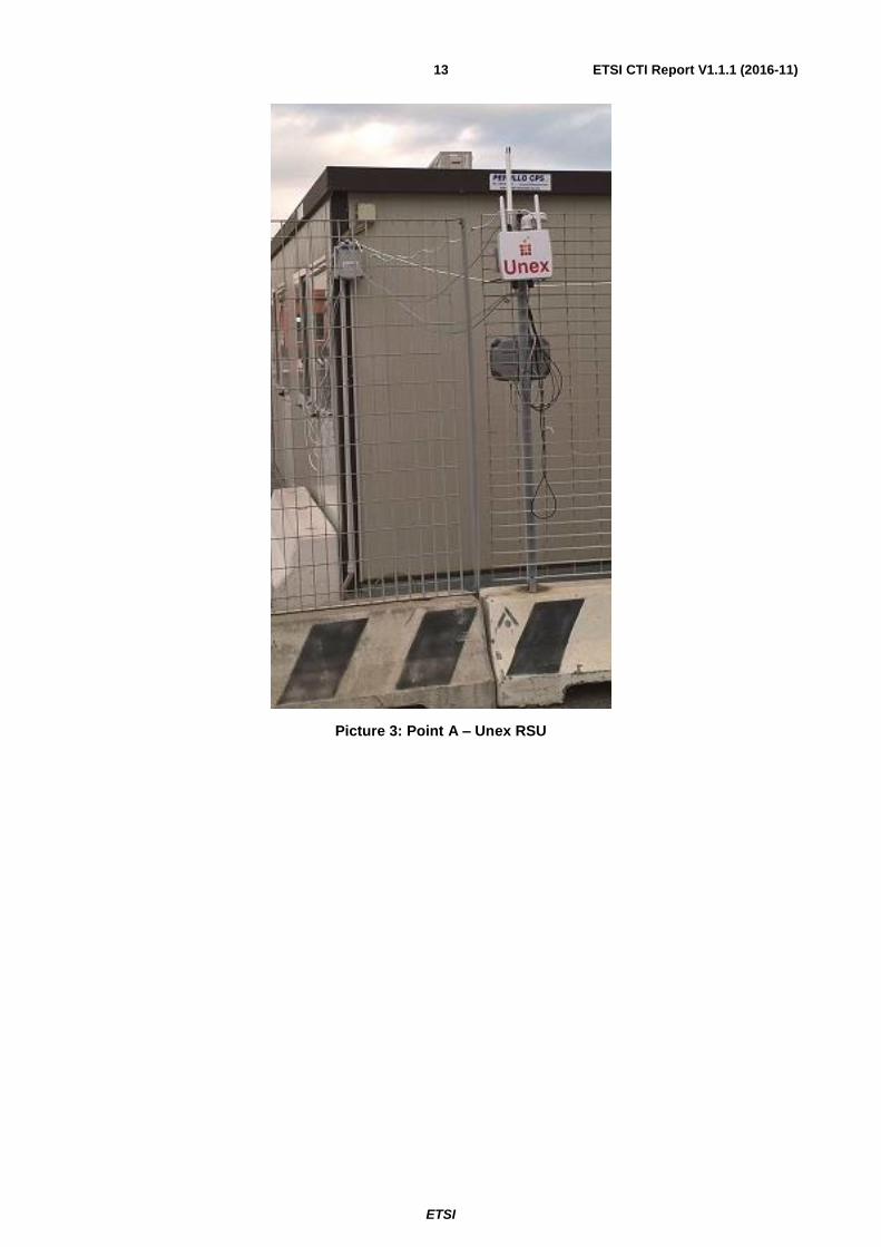
5.3.2.1 Point A
Picture 1: Point A – Commsignia Traffic Light

ETSI
ETSI CTI Report V1.1.1 (2016-11) 12
Picture 2: Point A – Commsignia RSU
ETSI
ETSI CTI Report V1.1.1 (2016-11) 13
Picture 3: Point A – Unex RSU

ETSI
ETSI CTI Report V1.1.1 (2016-11) 14
5.3.2.2 Point B
Picture 4: Point B – NXP Traffic Light (with Dynniq Traffic Light Controller)
Picture 5: Point B – Cnit, Dynniq and Yogoko RSUs

ETSI
ETSI CTI Report V1.1.1 (2016-11) 15
5.3.2.3 Point C
Picture 6: Point C – Neavia traffic light
Picture 7: Point C – Aricent, Neavia, Swarco and Siemens RSUs

ETSI
ETSI CTI Report V1.1.1 (2016-11) 16
5.3.2.4 Point D
Picture 8: Point D – Qfree traffic light
Picture 9: Point D – Ctag, Savari, Kapsch and Qfree RSUs
5.3.3 Highway test track
The highway test track consisted of a section of the Livorno/Florence highway as shown in the picture below

ETSI
ETSI CTI Report V1.1.1 (2016-11) 17
Picture 10: Highway Test Track
AVR provided access to a gantry in which the RSUs from CNIT, Siemens and Swarco were installed. The RSUs were
connected with the Plugtest Test Network, i.e. interconnection of AVR control room, RSUs, Plugtests headquarter and
remote labs in Stuttgart, Germany and Vienna, Austria. The picture below shows the RSUs from Siemens and Swarco.
Picture 11: Highway Test Track – Siemens and Swarco RSUs
For the UC1 – Road Works Warning the leftmost lane of the highway was closed. In the picture below the closed lane is
shown, and the RSUs in the gantry are visible.

ETSI
ETSI CTI Report V1.1.1 (2016-11) 18
Picture 12: Highway Test Track – closed lane and RSUs in gantry
5.3.4 Plugtest Headquarter
The Port Authority provided the cruise terminal which was used as Plugtest headquarter. More than 80 tables were
installed to seat the organizers as well as the participants. The Plugtest headquarter is shown in the picture below.
ETSI
ETSI CTI Report V1.1.1 (2016-11) 19
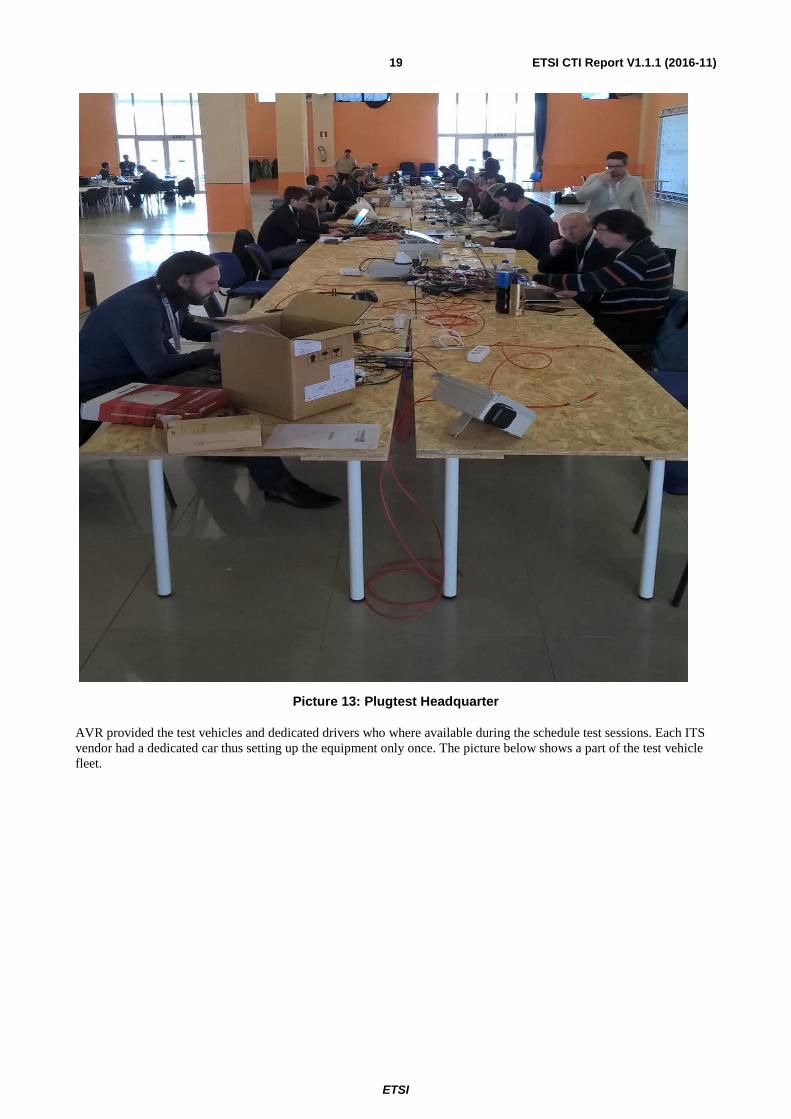
Picture 13: Plugtest Headquarter
AVR provided the test vehicles and dedicated drivers who where available during the schedule test sessions. Each ITS
vendor had a dedicated car thus setting up the equipment only once. The picture below shows a part of the test vehicle
fleet.

ETSI
ETSI CTI Report V1.1.1 (2016-11) 20
Picture 14: Fleet of test vehicles parked in front of the Plugtest headquarter
The ‘Port Innovation Workshop’ took place in parallel with the Plugtest. Workshop participants could explore the
Plugtest exhibition corner and take a demo ride with the test vehicles. The Plugtest exhibition and the demo rides were
organized at the Plugtest headquarter. The picture belwo shows the Plugtest exhibition corner.

ETSI
ETSI CTI Report V1.1.1 (2016-11) 21
Picture 15: Exhibition area
The picture below shows the workshop attendees waiting for their demo ride with one of the test vehicles.

ETSI
ETSI CTI Report V1.1.1 (2016-11) 22
Picture 16: Queue for demo rides
5.3.5 GPSD Server
The GPSD server emulated the movement of cars of the Zone 1 of the test track. It provided different positions for each
vendor in order to avoid position collisions. All positions and port allocations were presented at the GPSD server web
interface. The GPSD server was synchronized with the local NTP server on time.windows.com
The source code for the GPSD server is available at https://forge.etsi.org/svn/_ITS_GPSD_SERVER/branches/
5.3.6 PKI Setup
For the Plugtest two PKIs were provided. One PKI from Escrypt. The other PKI from SystemX. The PKIs enabled to
retrieve ITS certificates as defined by ETSI TS 103 097 v1.2.5. The communication with the PKI provided by Escrypt
was done using HTTP over TCP over IP (IPv4) using a SOAP web service secured with TLS. The communication with
the PKI provided by SystemX was done using HTTP over TCP over IP (IPv4) secured with ETSI TS 102 941 v1.1.9.
This setup allowed to test a real deployement scenario were a vehicle needs to trust more than one PKI provider.
5.3.7 DATEXII Integration
One of the objectives of the Plugtest was to demonstrate conformance and interoperability of the communication on the
G5 radio, under real life conditions, with the end-2-end equipment chain from Traffic Control Center to Applications in
the test vehicles.
Autostrade provided with the access to their DATEXII node an important element of this equipment chain. The system
architecture of the DATEXII integration is shown in the figure below.

ETSI
ETSI CTI Report V1.1.1 (2016-11) 23
Figure 1: DATEXII Integration
To widen the participation of vendors to this integration and to support the implementations coming from earlier
European projects, three different communication interfaces were provided:
Basic DATEX http/get interface
Basic DATEX WSDL push/pull interface
DATEX content by OCIT-C interface
In addition a conversion from DATEX format to XER DENM had been implemented by Autostrade from their DATEX
System (DATEX 2 C-ITS Adaptor in the figure above) acting as a C-ITS-S delivering messages to R ITS-S. A detailed
interface to provide XER DENM messages to R ITS S was developed.
The architecture set up supported vendors that implemented CITS-Ss to interact with the Traffic Control Centers as well
as vendors that implemented RSUs to interact with the Traffic Control Center. The data flow contained real events from
the test site (i.e. road events about FiPiLi and Motorway) and simulated events.
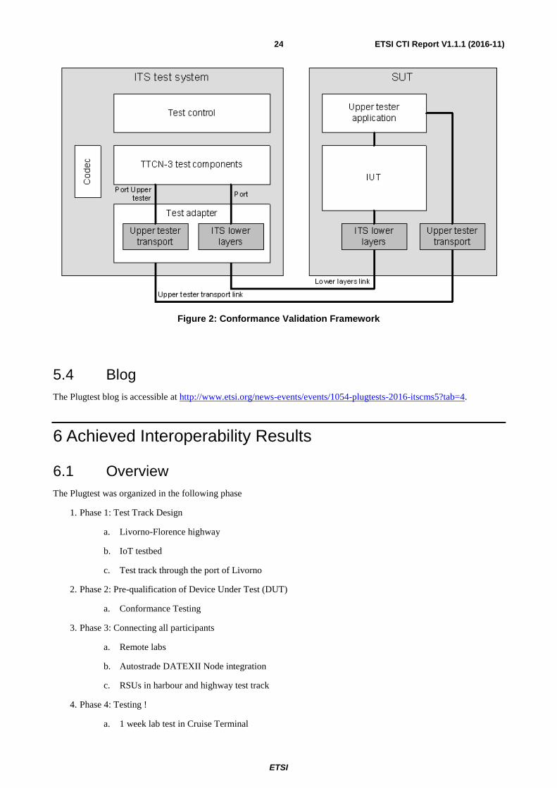
5.3.8 Conformance Validation Framework
The ETSI ITS Conformance Validation Framework is a test software to assess the base standard compliance of a vendor
implementation, as shown in the figure below. The Conformance Validation Framework was used for the pre-testing
activity, see clause 6.2 .
ETSI
ETSI CTI Report V1.1.1 (2016-11) 24
Figure 2: Conformance Validation Framework
5.4 Blog
The Plugtest blog is accessible at http://www.etsi.org/news-events/events/1054-plugtests-2016-itscms5?tab=4.
6 Achieved Interoperability Results
6.1 Overview
The Plugtest was organized in the following phase
1. Phase 1: Test Track Design
a. Livorno-Florence highway
b. IoT testbed
c. Test track through the port of Livorno
2. Phase 2: Pre-qualification of Device Under Test (DUT)
a. Conformance Testing
3. Phase 3: Connecting all participants
a. Remote labs
b. Autostrade DATEXII Node integration
c. RSUs in harbour and highway test track
4. Phase 4: Testing !
a. 1 week lab test in Cruise Terminal
ETSI
ETSI CTI Report V1.1.1 (2016-11) 25
b. 1 week of field tests on test track
The following clauses cover all phases.
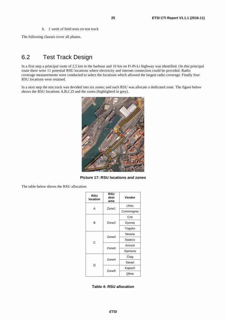
6.2 Test Track Design
In a first step a principal route of 2,5 km in the harbour and 10 km on Fi-Pi-Li highway was identified. On this principal
route there were 11 potential RSU locations where electricity and internet connection could be provided. Radio
coverage measurements were conducted to select the locations which allowed the largest radio coverage. Finally four
RSU locations were retained.
In a next step the test track was devided into six zones; and each RSU was allocate a dedicated zone. The figure below
shows the RSU locations A,B,C,D and the zones (highlighted in grey).
Picture 17: RSU locations and zones
The table below shows the RSU allocation.
RSU location
RSU dest area
Vendor
A Zone1 Unex
Commsignia
B Zone2
Cnit
Dynniq
Yogoko
C
Zone3 Neavia
Swarco
Zone6 Aricent
Siemens
D
Zone4 Ctag
Savari
Zone5 Kapsch
Qfree
Table 4: RSU allocation

ETSI
ETSI CTI Report V1.1.1 (2016-11) 26
Then a GPS recording of the vehicle path was created. Based on this GPS recording the zone-specific messages were
designed, i.e. the DENM traces, MAP stop lines, reference points etc were chosen in reference to the GPS recording.
6.3 Pre-testing
Before attending the Plugtest the participants were offered the possibility to validate their compliance to the ETSI
Release 1. This step in the Plugtest preparation was important, as it helped to detect and mitigate potential errors early
on, rather than having to debug these issues in the field on the test track.
Table 5: List of available test specifications
Base Standard ETSI Test Specifiction
ETSI EN 302 637-2 v1.3.2: CAM base specification ETSI TS 102 868-1,2,3 (V1.4.1 available in Feb 2017)
ETSI EN 302 637-3 v1.2.2: DENM base specification ETSI TS 102 869-1,2,3 (V1.5.1 available in Feb 2017)
ETSI EN 302 636-4-1 v1.2.1: GN base specification ETSI TS 102 871-1,2,3 (V1.4.1 available in Feb 2017)
ETSI TS 103 097 V1.2.1: Security header and certificate
formats
ETSI TS 103 096-1,2,3 (V1.3.1 available in Feb 2017)
ETSI TS 103 301 V1.1.1: Infrastructure Services ETSI TS 103 191-1,2,3 (V1.2.1 available in Feb 2017)
Note : The test scripts are developed in TTCN-3 (for more information on TTCN-3 see www.ttcn-3.org)
The tests are available at the following location (login: snvusers, pwd: svnusers).
ASN.1 files
https://forge.etsi.org/svn/ITS/branches/STF517/asn1/
ATS
https://forge.etsi.org/svn/LibIts/branches/STF517/ttcn
LibIts
https://forge.etsi.org/svn/LibIts/branches/STF517/ttcn
LibCommon
https://forge.etsi.org/svn/LibCommon/tags/v1.4.0/ttcn
Codec/TA
https://forge.etsi.org/svn/ITS/branches/STF517/javasrc
To support the debugging of detected compliance problems ETSI developed a dissector for Wireshark. Thsiis available
at https://forge.etsi.org/svn/WIRESHARK_ITS_PLUGINS/releases.
Note: It is planned to release the ITS test specifications via TC ITS in early 2017. The release will include bug fixes of
issues found during the PLugtest, but will not differ in any other way. This upcoming release can hence be used as
reference for future projects..
6.4 Connecting All Participants
The remote test infrastructure was based on the connection of all the Equipment Under Test from all the participating
companies to the Hub for Interoperability and Validation at ETSI (HIVE) via IPSec GRE VPN Tunnels.

ETSI
ETSI CTI Report V1.1.1 (2016-11) 27
In this setup, ETSI acted as a VPN HUB and enabled the interaction among any possible equipment combination over a
secure transport network.
Consequently, connecting the equipment under test to HIVE was a mandatory step to being able to participating to the
remote pre-testing phase of the Plugtest.
In order to facilitate the integration of remote companies the following initiatives were put in place:
1) A VPN Request application accessible from the WIKI allowing participants to fill-in all their technical details
and to automatically trigger the VPN configuration and setup.
2) A pre-configured VPN Router loan service. ETSI put in place this fast-track process with the objective to
accelerate the integration of Plugtest participants. Participants that wished to benefit from this possibility could
request it on the VPN request application, and received within a few days a pre-configured VPN router
allowing them to connect their equipment under test to HIVE within a few minutes.
The VPN request application also allowed participants and organisers to monitor the status of the VPN creations.
Figure 3. VPN Request application
A flexible network architecture was designed to enable inter-connection of Central ITS-S located at remote labs, RSU
on the harbour test track, RSU on the highway test track and monitoring and control equipment at the Plugtest
headquarter.

ETSI
ETSI CTI Report V1.1.1 (2016-11) 28
Figure 4. Network Architecture
6.5 Lab Mega Session
During the first week of the Plugtest the OBUs and HMIs were validated by sending from the ETSI RSU simulator pre-
defined messages according to the Use Case constraints. RSU vendors had as well the opportunity to send the pre-
defined messages thus validating their RSU-behaviour.This was the last check before going on the test track. The lab
mega session took place at the Plugtest headquarter. The code of the RSU simulator is available at
https://forge.etsi.org/svn/ITS/branches/STF517/ttcn/AtsRSUsSimulator .
The GPSD server provided the location information for the OBUs. It emulated the movement of cars of the Zone 1 of
the test track. It provided different positions for each vendor in order to avoid position collisions. All positions and port
allocations were presented at the GPSD server web interface. The GPSD server was synchronized with the local NTP
server on time.windows.com. The source code for the GPSD server is available at
https://forge.etsi.org/svn/_ITS_GPSD_SERVER/branches/
6.6 IoT Use Cases
6.6.1 Introduction
The Plugtest tested in real-life conditions innovative IoT-ITS scenarios: an event detected at the IoT gateway is notified
to the surrounding vehicles through the ITS stack. The events tested covered environmental sensing (hazard or
pedestrian on the road, loading / unloading zone management) and on board sensing ( vehicle with dangerous goods on
the road).
6.6.2 Testplan and use cases
Three use cases were planned for the joint IoT-ITS tests. These tests involved smart objects connected to an M2M
gateway located either in an OBU (UC2) or an RSU (UC1 and UC8). When triggered by the reported value received
from the smart object, the ITS station would disseminate an ITS message to notify the surrounding ITS stations. The
protocol stack illustrated in figure 5 was adopted for the tests.

ETSI
ETSI CTI Report V1.1.1 (2016-11) 29
Figure 5: IoT-ITS protocol stack
UC1: Hazard on the road
The objective of this test is to notify ITS stations that a danger on the road (pedestrian, fuel, …) has been detected by an
IoT-enabled smart object. The RSU polls the IoT device, and if a condition is met, it broadcasts a corresponding DEN
Message to the surrounding vehicles indicating the hazard position.
UC2: Dangerous goods vehicle
The objective of this test is to notify ITS stations that a vehicle carrying dangerous goods is driving or stopped on the
road. An IoT-enabled smart object is installed in the vehicle. The OBU of the vehicle polls the device and transmits a
CA Message indicating “dangerous goods vehicle” information to the surrounding vehicles. If the vehicle stops on the
road, it transmits a warning in a corresponding DEN Message.
UC8: Loading / Unloading Zone management
The objective of this test is to notify ITS stations that a loading / unloading parking space is available in the harbour.
The RSU polls an IoT device, and if a parking place is detected as free, it broadcasts a corresponding PoI Message to
the surrounding vehicles indicating the loading/ unloading zone position. The PoI message used for this test was a
deviation of the EVCSN (Electric Vehicle Charging Spot Notification) message specified in ETSI TS 101 556-1.
6.6.3 Participants
The participants to the IoT-ITS tests were divided in the following categories.
- Smart object providers: three participating companies provided their sensors, based on Infra-red, magnetic detection or
RFID security seal: Aricent, LeghornGroup and NGS.
- IoT gateway - ITS stations: two participating companies provided ITS stations able to communicate with the sensors:
CNIT and Aricent. Both companies were able to provide an OBU for UC2 as well as an RSU for UC1 and UC8.
- Receiving ITS stations were standard OBUs for UC1 and UC2. UC8 necessitated the support of the PoI message by
the OBU, which was provided by three companies: CNIT, Aricent and CTAG.
6.6.4 Test preparation
A test plan covering all three use cases was developed and maintained during the preparation time (clause 6 “IoT Test
Scenarios” of the CMS5 Plugtests Guide).
The IoT specific use cases were discussed during the regular CMS5 phone calls, and during two additional dedicated
calls held on 08/09/2016 and 20/10/2016. Clarifications were already discussed during these calls, such as:
- confirmation of detection method: no pre-defined DENM, the initial detection takes place at the start of each session
and is valid for the whole session duration (e.g., no real human to trigger the pedestrian on the road hazard, but rather
use the manual trigger of a real sensor),
- list of devices available for the tests and their capabilities,
- protocol stack to be used (see Figure 5), the communication between the sensor and the gateway is IEEE 802.15.4
(short range),
- communication between the IoT device and the gateway, based on polling rather than pushing (CoAP periodic GET
method rather than OBSERVE, which however would be less power consuming in real life),
- integration of the gateway with the ITS station by each vendor (interoperability at IoT level is not in the objectives),

ETSI
ETSI CTI Report V1.1.1 (2016-11) 30
- access layer channel used for UC8 is the ITS G5-CCH with the channel number 180, even if in real life it should be a
service channel,
- periodicity of the ITS messages to be sent,
- insertion of the DENM cause codes to be used in the wiki for each use case.
6.6.5 Illustration of tests
The IoT tests were integrated in the main Plugtests schedule and run mainly from zone 2 (CNIT RSU located in point
B) and zone 6 (position of Aricent RSU in point C). The pictures below illustrate these tests.
Figure 6: RSU from CNIT with NGS sensor
Figure 7: RSU from Aricent

ETSI
ETSI CTI Report V1.1.1 (2016-11) 31
Figure 8: Vehicle carrying dangerous goods
Figure 9: Screen capture logging IoT and ITS DENM messages for UC1
Figure 10: Display showing result of UC2
Figure 11: Display showing result of UC8

ETSI
ETSI CTI Report V1.1.1 (2016-11) 32
6.6.6 Dissemination
This IoT-ITS Plugtests campaign was presented at the ETSI IoT / M2M workshop, on November 17, in ETSI
Headquarters. A copy of the final presentation is available at:
https://docbox.etsi.org/Workshop/2016/201611_M2MIoTWS/00_WORKSHOP/S08_IoTinVERTICALS/CNIT_Petracc
a.pdf
6.7 ITS Use Cases
Per round on the test track up to four tests could be executed. More than 370 test result were reported with a toal of 80%
interoperability as shown in the table below.
Table 6: Overall result
Interoperability
OK NO Run
300 (80.0%) 75 (20.0%) 375
A highlight of the Plugtest was the fact that many well advanced applications were deployed. UC3 - Time To Green and
UC6 - Intersection Collision Risk Warning were ideal for the demonstration of the applications.
In the following clauses each use case is shortly discussed. The discovered interoperability issues are described in
clause 6.8 .
6.7.1 UC1 - Road Hazard Signalling
14 RSUs and 15 OBUs performed this use case on the harbour test track as well as on the highway test track. The
change request on DrivingLaneStatus was successfully validated, see also clause 7.4 and Annex A.
6.7.2 UC3 - Time To Green / Traffic Sign Violation
12 RSUs and 13 OBUs performed this use case. Many vendors agreed that the current SPAT Timemark is not the most
efficient way to indicate timing.
6.7.3 UC4 - Vehicle Data Aggregation
7 RSU vendors performed this use case. Each RSU individually captured the traffic.
6.7.4 UC5 - In-Vehicle Signage
10 RSUs and 9 OBUs performed this use case. This was a straight forward test, however it was agreed that the IVI
ASN.1 typing is too complex and hence can easily cause interoperability issues.
6.7.5 UC6 - Intersection Collision Risk Warning
8 OBUs performed this use case. This use case was validated successfully and each vendor had a well working
application.
6.7.6 UC7 - Longitudinal Collision Risk Warning
6 OBUs performed this use case.

ETSI
ETSI CTI Report V1.1.1 (2016-11) 33
6.7.7 UC9 - Tolling
7 RSU vendors and 9 OBUs performed this use case on the harbour test track as well as on the highway test track. Each
OBU vendor could decode the ProtectedCommunicationZonesRSU CAM message sent by the RSUs and apply the TX
power reduction mitigation method.
6.7.8 Security
6.7.8.1 Secured Communication
14 vendors did run the use cases UC1, UC3 and UC5 in secured mode successfully, both in the mega session as well as
on the test track.
A highlight of the secured mode test session was that simultaneous usage of two PKIs was successfully tested. One
vendor used certificates provided by Escrypt PKI and 3 other vendors used certificates provided by SystemX PKI.
These vendors could communicate together in secured mode on the test track.
6.7.8.2 Certificate Reloading (UC10)
10 vendors were able to obtain certificates in the lab using an IPv4 connection to the PKIs.
2 vendors were able to obtain certificates on the track using IPv6 over G5.
6.8 Interop Issues
6.8.1 IoT
Interpretation of the IoT device signal. The main issue was whether subsequent active detections (e.g. for
pedestrian) should be considered as new events or the same event. The initial settings tested considered them
as different events, thus triggering a new DENM with a different sequence number at each period, i.e. every
second. The OBUs receiving the messages were then rapidly flooded by this large set of DENMs. In a first
step, it was agreed to send the messages with a longer period of 5 seconds, and set the message validity
duration to 4.5 s. In real life the tests would rather use the AppDENM_update application request, as specified
in the DEN basic service standard, ETSI EN 302 637-3. This issue has demonstrated the necessity to clearly
define (maybe with specific new standards) the interpretation of sensor data and how they trigger actions from
the applications.
Some issues were encountered in the construction of the DENM messages by the testing IoT-ITS stations,
mainly for indicating the position of the event, the relevance distance (without location container, as it was not
required here) and the value of the repetition interval. Most of them were fixed during the event to enable the
validation of the results.
6.8.2 GPS
The zone 1 of the Harbour test track, see picture below, was a challenge for the GPS signals. The presence of the high
boat on the left facing the high building on the right created an environment typical of an urban canyon. This well-
known issue of GPS geo-positioning in this type of environment results from the partial blocking of satellite signal
reception (in the GPS system, the higher the number of different satellite signals received, the better the accuracy of the
positioning is) as well as the multipath reflections on the building and even more, on the metallic side of the boat. The
result is a lack of accuracy of the GPS positioning, as was experienced by some of the OBU receivers during the test.
When monitoring vehicle traces through the received CAM messages, the apparent vehicle position has been often 10-
20 meters off the road. Such positioning inaccuracies cause problems for use cases which rely on the position/heading
of the vehicle, such as red light violation warning or intersection collision warning. It demonstrates that GPS
positioning is not sufficient for traffic safety applications, and that fusion algorithms with complementary positioning
systems are required. During the wrap-up sessions the participants were informed of two projects which address this
topic:
Ongoing project: the HIGHTS project (http://hights.eu/ )

ETSI
ETSI CTI Report V1.1.1 (2016-11) 34
Completed project: A high-precision cooperative RTK GNSS positioning solution has been tested in the
AutoNet2030 project (www.autonet2030.eu). All metrics were collected in two different modes; cellular
(correction data coming from the SWEPOS network using a cellular modem), and ITS-G5 (correction data
coming from a base station SW calculation, broadcast over multi hop ITS-G5 short range communications).
For the position accuracy in the ITS-G5 case, the accuracy is dependent on the precise location of the base
station, which can be self-calibrated using long-term measurement averaging.
Lock time of the module is fairly long since it is using a single frequency receiver. Even though lock time was
in the order of minutes, it was discovered to be fairly constant. No difference could be seen between cellular
and ITS-G5 modes.
Position accuracy was measured against a Trimble system with proven high accuracy. The promised few cm
level accuracy compared to the Trimble ground truth was reached in all tests. Smoothness of the output was
also investigated and deemed to be correct, both in low-speed and high-speed dynamic driving scenarios. The
following figure illustrates the accuracy of the obtained position accuracy on a two-lane test track. It shows the
tracking of the vehicle in front from the perspective of the ego-vehicle in the middle; left side shows the radar
tracking view, while the brown line in the right side shows the GNSS trace of the vehicle which has been
communicated through the CAM message broadcasts. As can be seen from the figure, the obtained positioning
data can always unambiguously indicate the driven lane of the vehicle during this highway scenario test.
Figure 12: Urban canyon of test track
6.8.3 Backwards compatibility
6.8.3.1 MAP/SPAT versioning
There had been some discussions about the backward compatibility issue that arose with the MAP/SPAT ASN.1
definitions for the Plugtest.
The Plugtest 2015 used a version of SPAT/MAP messages which is different to the version used in the Plugtest 2016.
Therefore TS 103 301 v1.1.1 should state : “For the present document, the value of the DE protocolVersion for SPAT,
MAP etc shall be set to 2.” However it was decided not to insist on the change to TC ITS WG1 due to the fact that a)
the vendor parameter profiles were already frozen at the time of this discussion and b) the approval of TS 103 301
v1.1.1 had just finished.
6.8.3.2 Version Handling
At the moment CDD TS 102 894-2 v1.2.1 is published;

ETSI
ETSI CTI Report V1.1.1 (2016-11) 35
In case a non-backwards compatible CDD is released, and the facility layer standards weant to use this new CDD
version, then they must be updated as well. For example of CAM the following steps would need to be
undertaken:
o raise the protocolVersion number in CAM EN 302 637-2 (the CDD.protocolVersion is used to
indicate the version of a facility layer message, e.g. CAM, DENM, SPAT, MAP, IVI, …)
o update the normative reference section of CAM EN 302 637-2 and point to CDD v1.3.1
As a consequence the value ‘currentVersion(1)’ should be deleted from CDD.protocolVersion. This would
remove the ambiguity whether this value 1 applies to CDD or the facility layer messages.
CDD versions shall be managed via the document version , i.e. V1.2.1, V1.3.1 … .
6.8.4 Traffic Control Center
A total of four vendors integrated with the Autostrade DATEXII node as shown in the table below. A highlight was that
one of the vendors installed its RSU in a gantry of the highway test track.
Table 7: Autostrade connections
RSU location Message Content Device Type Feed
Vendor1 RSU on highway Real Motorway roadworks Central ITS-S OCIT-C
Vendor2 RSU on test track Simulated Harbour roadworks (3 lanes) RSU REST DENM XER
Vendor3 RSU on test track Simulated Harbour roadworks (3 lanes) RSU REST DENM XER
Vendor4 RSU on test track Simulated Harbour roadworks (3 lanes) RSU REST DENM XER
Autostrade Connection
Most of the issues faced during the integration between ITS-Ss and the Traffic Control Center were caused by a lack of
extensive pre-testing activity and discussion over the provided documentation. The main issues faced included:
1. Connectivity issues among remote sites;
o The pre-testing phase was not long enough to debug all connectivity issues.
2. Non-conformant DATEXII implementations
o validityStatus Management:
the standard validityStatus provides the following options ( definition available on DATEX reference
document): active, definedByValidityTimespecs, suspended. In addition the status ‘closed’ was
required by some vendors, and the status ‘suspended’ was used to indicate ‘closed’. The correct
implementation would have been to extend the ValidityStatus with a “closed” situation record.
o situation ID
No semantic should be superimposed on it, i.e. treating situation ID to be the same as actionID in
DENM Messages can lead to problems on the DATEXII side.
3. DATEX II content to DENM mapping
The DATEX II content was filtered geographically and by content to suit the Plugtets use cases.
PublicationDifficulties to set up simulated events in the DATEXII flow were encountered, which led to
messages non conformant with interoperability test specifications;
4. DENM XER flow: most of the issues have been dealt with on site and a successful integration of UC1 was
achieved. The only issue reported consisted of a not correctly formatted trace for the event. Still the
notification was provided to the HMI by means of the Relevance Area data frame present in the message.
6.8.5 Security
The two PKI providers had implemented the certificate distribution differently. At the Plugtets most of the vendors had
implemented the standardized certificate distribution, i.e. ETSI TS 102 941. The C2C PKI protocol is not compatible
ETSI
ETSI CTI Report V1.1.1 (2016-11) 36
with the ETSI standard and hence it is recommended to converge the various PKI implementations towards the new
release of TS 102 941. The following feedback was recorded.
6.8.6 DENM
The following interoperability issues were discovered:
validityDuration in the past,
WGS 84 altitude is around 50m, but OBUs reported 0m (altitude not available is 800001
detectionTime and referenceTime are wrong
Epoch time in ms used instead of TAI time
6.8.7 GN
The following interoperability issues were discovered:
Hopping activated
6.8.8 POTI
As at every Plugtest there are many issues with time synchronization, time format and GPS accuracy. It is therefore
recommended to conduct thorough POTI tests.

ETSI
ETSI CTI Report V1.1.1 (2016-11) 37
7 Base Specification Validation
All issues identified and listed in the present clause are minor issues and did not hamper the use case executions.
7.1 ETSI TS 103 301 v1.1.1
The table below lists the discovered base spec issues of ETSI TS 103 301 v1.1.1.
Table 8: Discovered IS base spec issues
# Issue Comment
1 All modules - named integers in the OID need to be unique throughout ASN.1 modules - Issue 7581 Issue fixed and
applied during
Plugtest
2 All modules - wrong OID in all modules - Issue 7582 Issue fixed and
applied during
Plugtest
3 IVI - type names should not be called ‘optional’ ‘mandatory’ - Issue 7579
4 IVI - Type and field names not descriptive enough - Issue 7578
5 IVI - Avoid inline definitions - Issue 7575
6 IVI - logical problems with TractorCharacteristics and TrainCharacteristics types - Issue 7577
7 IVI - how to handle future extensions - Issue 7576
8 IVI - 'TcPart / data' and 'Text / textContent' fields: OCTET STRING or UTF8String with a length limitation - Issue 7574
9 MAP - avoid length-specific ASN.1 typing - Issue 7580
10 IVIM.ivi.optional.gic SSP - Issue 7587
11 AdvisorySpeed SSP - Issue 7586
12 SPATEM.spat.intersections. IntersectionState.status is mandatory and hence cannot be SSPed - Issue 7585
13 SPATEM.spat.intersections. IntersectionState shoudl not be included in SSP - Issue 7584

ETSI
ETSI CTI Report V1.1.1 (2016-11) 38
14 protocolVersion should be set to 2 - Issue 7583
7.2 ETSI TS 103 097 v1.2.5
Based on various feedback such as the 4th ITS Plugtest, TC ITS WG5 had started end of 2015 to develp a bug fixed version based on v1.2.1. Six month prior to the 5th Plugtest
version v1.2.5 was produced with the goal to validate this snapshot. Version v1.2.5 was successfully validated in the Plugtest and the table below lists the discovered base spec
issues and potential fetaures of ETSI TS 103 097 V1.2.5.
Table 9: Discovered base spec issues and potential new features
1 Request of unrecognized AA certificate create high channel load when all receivers reply with a
certificate chain – Issue6969
2 ITS-S should stop requesting an unrecognized AA certificate if the issuer of the AA certificate is
untrusted – Issue6973
3 to add SSPs in the AA certificate – Issue 7559
4 SSP needs to be redesigned – Issue 7588
7.3 ETSI EN 302 637-3 V1.2.2
The table below lists the discovered base spec issues of ETSI EN 302 637-3 V1.2.2.
Table 10: Discovered DEN base spec issues
1 Negation of DENM is not protected by SSP - Issue - 7532
2 Improvement of the reference to related DEN messages for a specific traffic situation within a DEN
message - Issue 7498
3 pseudonym change for active DENMs – Issue6980 (item from 2015 Plugtest)
4 StationID collisions - Issue6981 (item from 2015 Plugtest)

ETSI
ETSI CTI Report V1.1.1 (2016-11) 39
7.4 ETSI TS 102 894-2-1 V1.2.1
The table below lists the discovered base spec issues of ETSI TS 102 894-2-1 V1.2.1 .
Table 11: Discovered CDD base spec issues
# Issue Comment
1 extend value for SPAT/MAP/IVI/SSM/SRM - Issue 7209 Issue fixed and applied during Plugtest
2 [DE_DrinvingLaneStatus]: make it unnamed list - Issue 7296 Issue fixed and applied during Plugtest
3 Delete assigned version number ItsPduHeader.protocolVersion -
Issue 7429
The item of table 13.2 was implemented by all vendors and validated successfully. For all details to this item refer to the annex A of the present document.
7.4 ETSI TS 101 556-1 V1.1.1
The table below lists the discovered base spec issues of ETSI TS 101 556-1 V1.1.1 .
Table 12: Discovered EVCSN base spec issues
# Issue Comment
1 Timestamp is not exported from ItsContainer - Issue - 7440 Issue fixed and applied during Plugtest
2 OID of CDD is wrong – Issue 7061 Issue fixed and applied during Plugtest

ETSI
ETSI CTI Report V1.1.1 (2016-11) 40
8 Results of Plugtest Survey
8.1 Review of feedback from Plugtest#4
Even though the first four days of the Plugtest#4 were focused on conformance testing, it was noted that still
more conformance testing prior to a next Plugtest is needed. A gating criteria to enter the Plugtest could be to
pass the conformance tests. This would allow to understand which features and to what level features are
supported; and consequently more effective scheduling could be done.
o A pre-testing was performed at Plugtest#5.
The success of the Plugtest#4 Live Demo opened the floor for discussion on the topic whether the scope of next
Plugtests should include field trials, as the majority of ITS vendors has passed all indoor lab tests, and would
be ready for more advanced and real-world test scenarios.
o The scope was shifted to field trials at Plugtest#5.
No Security Profile 3 tests were executed due to the open base spec issue on ITS-AID
o Test were available at Plugtest#5.
Make C2C CC profile available to all vendors of next plugtest (use only 1 profile in Europe for C2C
Communication)
o It was not managed to include to the scope C2C CC Appplication requirements.
GPSD server per test unit, with a web interface to switch scenario, and start/stop buttons for non-static scenarios.
o GPSD server web interface was enhanced with visualization of eqach vehicle position.
Make sure the GPSD server provides correct speed, time and heading info.
o This was achieved.
Preparing the scenario per test takes a lot of time, use the upper tester interface to drive the test units? Make sure
test parameters are machine readable (XML, JSON etc.)
o In 2017 ETSI will automate the lab interop scenarios.
Prepare IOP set-ups to test over Ethernet. Many vendors support this, and it saves a lot of hassle with attenuators
and spurious messages from other teams.
o Face-to-face setups were out of scope at Plugtest#5.
Perhaps there should be a central "issues" white board next to the forwarding setup to write down problems with
the equipment. Several testers repeatedly had to identify the same issues.
o Forwarding was not tested at Plugtest#5.
Scope for a next event
o DCC (Sensitivity threshold correction, energy threshold test, header decoding test, DCC stability)
This feature was out of scope.
o SPAT/MAP/IVI/SAM
Partly achieved through UC3 and UC5.
o Pseudonym Change with changing GN address and Station ID
This feature was out of scope.
ETSI
ETSI CTI Report V1.1.1 (2016-11) 41
o Day one applications (including GLOSA); Test only features relevant for Day 1, e.g. no GeoUnicast,
no TSB , no KeepAlive , i.e. like C2C CC Profile
Mostly achieved except C2C CC profile.
o More security tests for exceptional behavior of DENM and conformance of certificates
Security conformance test suite has exceptional behaviour implemented.
o Traces / PathHistory . Test that data is interpreted correctly
Not achieved.
o Include road operator in test infrastructure
Achieved with integration of Autostrade.
o Out of band emission
This feature was out of scope.
o CAM Coexistence feature
This feature was achieved with UC9.
o Performance / High load scenarios
This feature was out of scope.
o Fast Verification
This feature was out of scope.
o More channel simulation testing
This feature was out of scope.
8.1 Feedback from Plugtest#5
Indoor lab: More face-to-face testing would have been helpful.
A central monitoring station would have enabled a more thorough validation of the frames sent on the outdoor
testtrack.
Having at least two time slot to test the same test.
Provide all test parameters (pre-defined messages) in machine readable format and in WSG84 coordinates.
Scope for a next event
o Performance / High load scenarios
o More channel simulation testing
o Traffic Jam Use Case
o Emergency Vehicle Use Case
o Adverse Weather Use Case
o EEBL Use Case
o RTK support from RSU to OBU
o More advanced IVI and SPAT/MAP tests
o SERM/SSEM

ETSI
ETSI CTI Report V1.1.1 (2016-11) 42
o Use of the vehicular CAN bus to trigger events
o Massive amount of cars: e.g. 200 cars in sight; 20 new cars/s, 2000 messages
o Security interoperability also including BSI PKI architecture and certificates
o Internet of things enabling autonomous driving cars
o DCC (Sensitivity threshold correction, energy threshold test, header decoding test, DCC stability)
Annex A: Change Request from German Corridor Project
A.1 LanePosition and DrivingLaneStatus
A.2 NamedBitList
A.2.1 Introduction
The DrivingLaneStatus is a length-constrained BIT STRING with ‘NamedBitList’ and shall be encoded following rule
16.3 of X.691 (see Annex of the present document). As a consequence, the original length (2 bits) and trailing zeroes
are not encoded. This means that the bit string 0100 (a road with 3 lanes + hard shoulder where only the outermost is
closed) will be received as 01, as the UPER allows dropping the last 2 zeroes. The result is that the receiving cars
cannot know a priori that the road is actually composed by 1 hard shoulder + 3 lanes and that the 2 leftmost are open.
On the contrary, when only the innermost lane is closed (0001), then the transmitted bit string gets no modification

ETSI
ETSI CTI Report V1.1.1 (2016-11) 43
(which allows the receiving car to have a full picture of the number of lanes of the carriageway and their driving lanes
status).
To solve this inconsistency the definition could be changed
from
DrivingLaneStatus ::= BIT STRING {outermostLaneClosed(1), secondLaneFromOutsideClosed(2)} (SIZE (1..14))
to
DrivingLaneStatus ::= BIT STRING (SIZE (1..14))
This would mean that clause 22.7 does no longer apply and the clause 16.11 applies instead; which results in not
removing trailing zero bits.
A.2.2 Type Change Proposal
ETSI TS 102 894-2 V1.2.1
Bit-Schema DEFINITIONS AUTOMATIC TAGS ::=
BEGIN
ExampleOld ::= SEQUENCE {
drivingLaneStatus DrivingLaneStatus
}
DrivingLaneStatus ::= BIT STRING { outermostLaneClosed(1), secondLaneFromOutsideClosed(2) }(SIZE (1..14))
END
ETSI TS 102 894-2 next version
Bit-Schema DEFINITIONS AUTOMATIC TAGS ::=
BEGIN
ExampleNew ::= SEQUENCE {
drivingLaneStatus DrivingLaneStatus
}
DrivingLaneStatus ::= BIT STRING (SIZE (1..14))
END
exampleOld ExampleOld ::= { drivingLaneStatus '0100'B } -> Encoded binary data 0x14 -> Decoded bitstring ‘01’B
exampleNew ExampleNew ::={drivingLaneStatus '0100'B }-> Encoded binary data 0x34 -> Decoded bitstring ‘0100’B
A.2.3 Conclusion
The two definitions encode differently, but a receiver can decode binary strings from both. Therefore there is 100%
backwards compatibility on a logical level). However, there is not 100% forward compatibility as a receiver which
decodes a binary string produced by an encoder following the old type definition will not get the full information of all
lanes.

ETSI
ETSI CTI Report V1.1.1 (2016-11) 44
Backwards compatibility is the most important feature and therefore the change can be introduced without increasing
the protocol version number of DENM.
The text in clause A.23 fo DENM needs to be changed to clarify the fact that the bitmap shows both open and closed
lanes.
Top Related